

Page 1
BladeCenter HT
Type 8740 and 8750
Installation and User's
Guide
Welcome.
This
contains information for setting
up and configuring your BladeCenter HT
unit and its components.
For additional information about
your BladeCenter HT device, view
the publications on the
Documentation CD.
also find the most
current information about
BladeCenter HT devices at
http://www.ibm.com/support/.
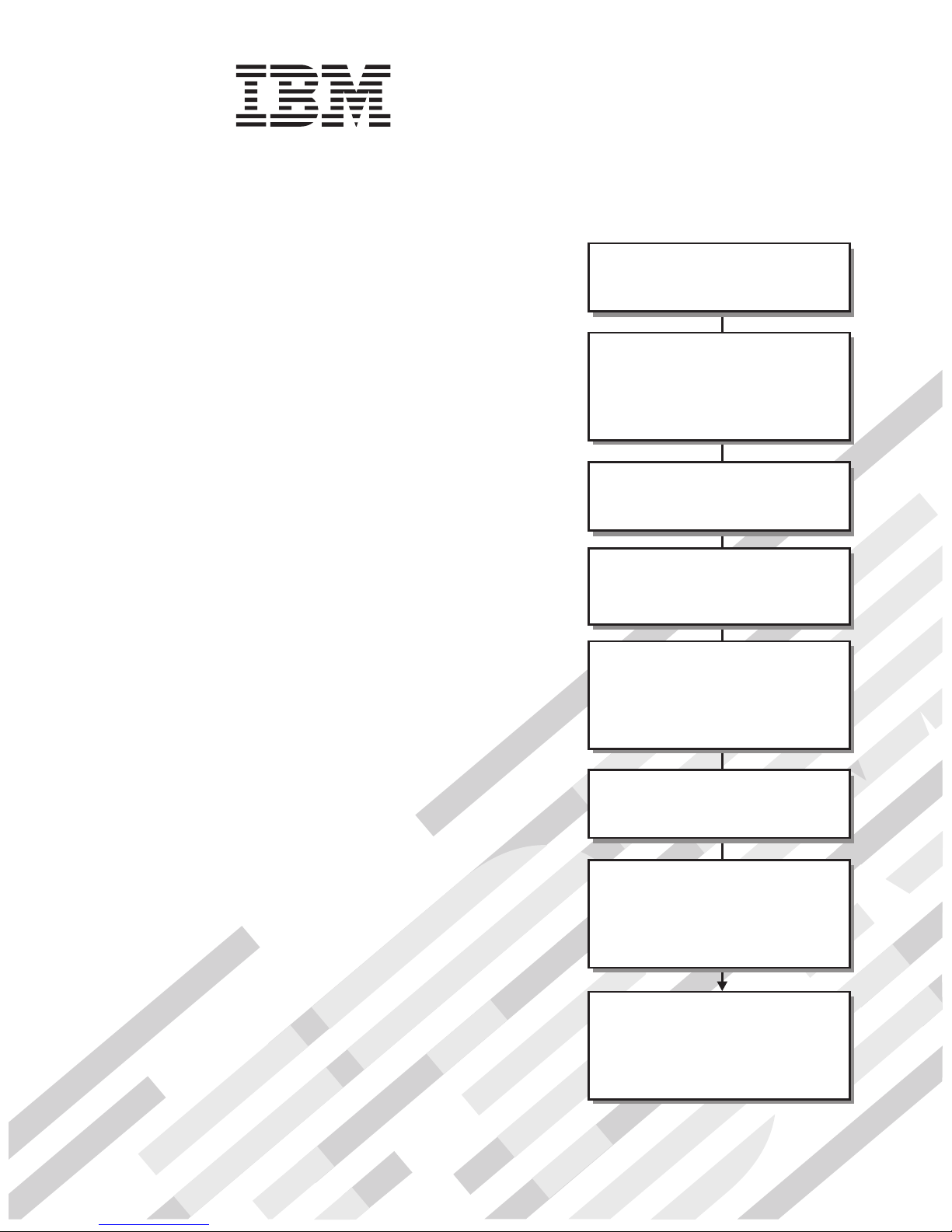
Installation and User's Guide
You can
Read the BladeCenter HT overview in
Define and document the configuration
parameters for your BladeCenter HT unit
using the worksheets in Appendix A of this
Set up your operating environment and
instructions that come with the rack.
Install the BladeCenter HT unit in the rack
using the instructions in the
HT 2-Post Rack Installation Instructions
4-Post Rack Installation Instructions.
or the
management modules in the BladeCenter HT
unit using the instructions in this
and User's Guide
Perform initial BladeCenter HT unit
configuration using the instructions in the
Management Module User's Guide.
Chapter 1 of this
Installation and User's Guide
Installation and User's Guide
install the rack using the
BladeCenter
Install the power modules and
Installation
and the documents
that come with each component.
.
.
Install and configure I/O modules in the
BladeCenter HT unit using the instructions in
Installation and User's Guide
this
and the documents that come
with each I/O module.
Install and configure blade servers in the
BladeCenter unit using the instructions in
this
Installation and User's Guide
and the documents that come
with each blade server.
Page 2
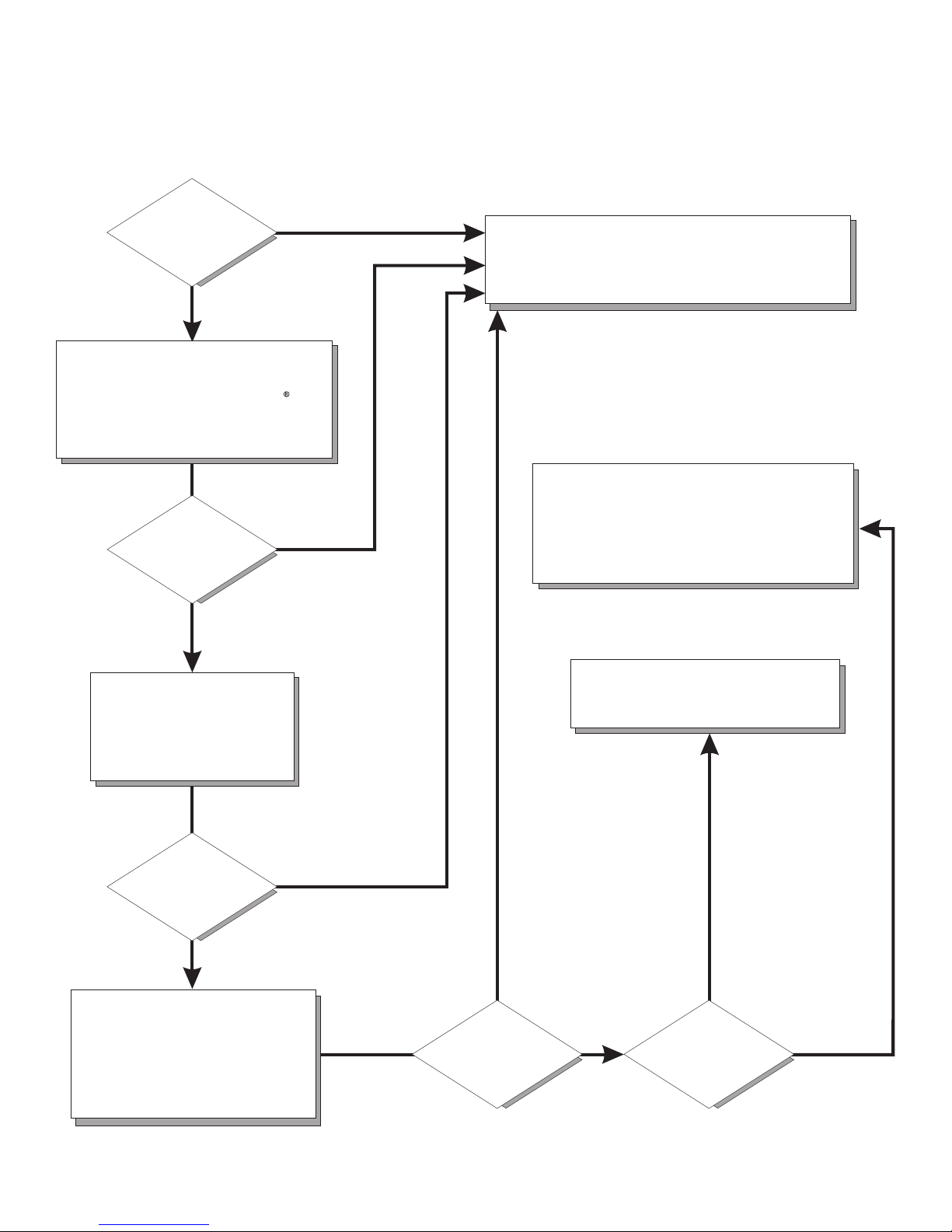
Server Support
Is the server working
correctly?
Ye s
No
Check all cables for loose connections
and verify that all optional devices you
installed are on the ServerProven list at
http://www.ibm.com/servers/eserver/
serverproven/compat/us/.
Is the problem
solved?
Ye s
No
Register the server. Go to
http://www.ibm.com/support/mysupport/.
View information about IBM Support Line at
http://www.ibm.com/services/sl/products/
or view support telephone numbers at
http://www.ibm.com/planetwide/.
See the troubleshooting
information that comes with
the server to determine
the cause of the problem
and the action to take.
Is the problem
solved?
Ye s
No
Update the firmware to the
latest level.
You can download firmware from
http://www.ibm.com/systems/
support
Ye s
Is the problem
solved?
View support telephone numbers at
http://www.ibm.com/planetwide/.
Hardware
No Software
Hardware or
software problem?
Page 3

BladeCenter HT Ty pe 87 40 and 8750
Installation an d User’s Guide
Page 4

Note:
Before using this information and the product it supports, read the general information in Appendix B, “Getting help and technical
assistance,” on page 81 and Appendix C, “Notices,” on page 83.
Third Edition (February 2008)
© Copyright International Business Machines Corporation 2008. All rights reserved.
US Government Users Restricted Rights – Use, duplication or disclosure restricted by GSA ADP Schedule Contract
with IBM Corp.
Page 5

Contents
Safety . . . . . . . . . . . . . . . . . . . . . . . . . . . . vii
Chapter 1. Introduction . . . . . . . . . . . . . . . . . . . . . .1
Locating and recording BladeCenter HT unit information . . . . . . . . . .2
Deployment scenarios . . . . . . . . . . . . . . . . . . . . . . .3
Features and specifications . . . . . . . . . . . . . . . . . . . . .4
The BladeCenter HT components . . . . . . . . . . . . . . . . . .5
Blade servers . . . . . . . . . . . . . . . . . . . . . . . . .5
Media tray . . . . . . . . . . . . . . . . . . . . . . . . . .5
Advanced management module . . . . . . . . . . . . . . . . . .5
I/O modules . . . . . . . . . . . . . . . . . . . . . . . . .6
Power modules . . . . . . . . . . . . . . . . . . . . . . . .6
Fan modules . . . . . . . . . . . . . . . . . . . . . . . . .6
Multiplexer expansion modules . . . . . . . . . . . . . . . . . .6
Alarm panel module . . . . . . . . . . . . . . . . . . . . . .7
The IBM BladeCenter HT Documentation CD . . . . . . . . . . . . . .7
Hardware and software requirements . . . . . . . . . . . . . . . .7
Using the Documentation Browser . . . . . . . . . . . . . . . . .7
Related documentation . . . . . . . . . . . . . . . . . . . . . .8
Notices and statements in this document . . . . . . . . . . . . . . .10
Major components of the BladeCenter HT Type 8740 and 8750 unit . . . . .11
Chapter 2. BladeCenter HT unit power, components, and indicators . . . .13
Supplying power to the BladeCenter HT unit . . . . . . . . . . . . . .13
Connecting the BladeCenter HT type 8740 to dc power: . . . . . . . . .14
Connecting the BladeCenter HT type 8750 to ac power: . . . . . . . . .16
Disconnecting power from the BladeCenter HT unit . . . . . . . . . . .16
BladeCenter HT components and LEDs . . . . . . . . . . . . . . . .18
Front view . . . . . . . . . . . . . . . . . . . . . . . . .18
Power modules . . . . . . . . . . . . . . . . . . . . . . .19
Media tray . . . . . . . . . . . . . . . . . . . . . . . .19
Management modules . . . . . . . . . . . . . . . . . . . .20
I/O modules . . . . . . . . . . . . . . . . . . . . . . . .20
Rear view . . . . . . . . . . . . . . . . . . . . . . . . . .21
Power connectors . . . . . . . . . . . . . . . . . . . . . .22
Fan modules . . . . . . . . . . . . . . . . . . . . . . . .22
Alarm panel module . . . . . . . . . . . . . . . . . . . . .22
Multiplexer expansion module . . . . . . . . . . . . . . . . .24
Chapter 3. Installing the BladeCenter HT unit and options . . . . . . .25
Installation checklist . . . . . . . . . . . . . . . . . . . . . . .25
Installing the BladeCenter HT unit in a rack . . . . . . . . . . . . . .26
Installation guidelines . . . . . . . . . . . . . . . . . . . . . .26
System reliability guidelines . . . . . . . . . . . . . . . . . . .26
Handling static-sensitive devices . . . . . . . . . . . . . . . . .27
Removing components from a BladeCenter HT unit . . . . . . . . . . .28
Removing a cable management tray . . . . . . . . . . . . . . . .28
Removing a power module . . . . . . . . . . . . . . . . . . .29
Removing a blade server . . . . . . . . . . . . . . . . . . . .30
Removing a media tray . . . . . . . . . . . . . . . . . . . . .31
Removing a CompactFlash module . . . . . . . . . . . . . . . .31
Removing an I/O module . . . . . . . . . . . . . . . . . . . .33
Removing an I/O-module interposer . . . . . . . . . . . . . . . .34
© Copyright IBM Corp. 2008 iii
Page 6

Removing a high-speed I/O module . . . . . . . . . . . . . . . .35
Removing a high-speed I/O-module interposer tray . . . . . . . . . .35
Removing a management module . . . . . . . . . . . . . . . . .36
Removing a management-module interposer . . . . . . . . . . . . .37
Removing a network clock filler . . . . . . . . . . . . . . . . . .38
Removing a multiplexer expansion module . . . . . . . . . . . . . .39
Removing an alarm panel module . . . . . . . . . . . . . . . . .40
Removing a fan module . . . . . . . . . . . . . . . . . . . .41
Removing a dc terminal cover . . . . . . . . . . . . . . . . . .42
Removing the fan shuttle . . . . . . . . . . . . . . . . . . . .43
Installing components into a BladeCenter HT unit . . . . . . . . . . . .44
Installing the fan shuttle . . . . . . . . . . . . . . . . . . . .45
Installing a fan module . . . . . . . . . . . . . . . . . . . . .46
Installing a network clock filler . . . . . . . . . . . . . . . . . .47
Installing a multiplexer expansion module . . . . . . . . . . . . . .48
Installing an alarm panel module . . . . . . . . . . . . . . . . .49
Installing a management-module interposer . . . . . . . . . . . . .50
Installing a management module . . . . . . . . . . . . . . . . .51
Installing an I/O-module interposer . . . . . . . . . . . . . . . . .52
Installing an I/O module . . . . . . . . . . . . . . . . . . . .53
Installing a high-speed I/O-module interposer tray . . . . . . . . . . .54
Installing a high-speed I/O module . . . . . . . . . . . . . . . . .55
Installing a CompactFlash module . . . . . . . . . . . . . . . . .56
Installing a media tray . . . . . . . . . . . . . . . . . . . . .57
Installing a power module . . . . . . . . . . . . . . . . . . . .58
Installing a blade server . . . . . . . . . . . . . . . . . . . .59
Installing the cable management trays without a bezel . . . . . . . . .60
Installing a dc terminal cover . . . . . . . . . . . . . . . . . . .61
Completing the installation . . . . . . . . . . . . . . . . . . . . .62
Chapter 4. Configuration and networking guidelines . . . . . . . . . .63
Configuring the BladeCenter HT unit . . . . . . . . . . . . . . . . .63
Configuring the management module . . . . . . . . . . . . . . . .63
Configuring I/O modules . . . . . . . . . . . . . . . . . . . .63
Configuring blade servers . . . . . . . . . . . . . . . . . . . .63
BladeCenter HT networking guidelines . . . . . . . . . . . . . . . .64
Chapter 5. IBM Director . . . . . . . . . . . . . . . . . . . . .65
Chapter 6. Shared BladeCenter HT resources . . . . . . . . . . . .67
Chapter 7. Solving problems . . . . . . . . . . . . . . . . . . .69
Diagnostic tools overview . . . . . . . . . . . . . . . . . . . . .69
Troubleshooting tables . . . . . . . . . . . . . . . . . . . . . .70
Monitor or video problems . . . . . . . . . . . . . . . . . . . .71
Power problems . . . . . . . . . . . . . . . . . . . . . . .71
Management module problems . . . . . . . . . . . . . . . . . .72
Fan module problems . . . . . . . . . . . . . . . . . . . . .73
Media tray problems . . . . . . . . . . . . . . . . . . . . . .73
Light path diagnostic LEDs . . . . . . . . . . . . . . . . . . . .74
Diagnosing problems by using diagnostic LEDs . . . . . . . . . . . .74
Diagnostic LEDs . . . . . . . . . . . . . . . . . . . . . . .74
Appendix A. BladeCenter HT management-module configuration worksheet 77
Appendix B. Getting help and technical assistance . . . . . . . . . .81
iv BladeCenter HT Type 8740 and 8750: Installation and User’s Guide
Page 7

Before you call . . . . . . . . . . . . . . . . . . . . . . . . .81
Using the documentation . . . . . . . . . . . . . . . . . . . . .81
Getting help and information from the World Wide Web . . . . . . . . . .81
Software service and support . . . . . . . . . . . . . . . . . . .82
Hardware service and support . . . . . . . . . . . . . . . . . . .82
IBM Taiwan product service . . . . . . . . . . . . . . . . . . . .82
Appendix C. Notices . . . . . . . . . . . . . . . . . . . . . .83
Trademarks . . . . . . . . . . . . . . . . . . . . . . . . . .83
Important notes . . . . . . . . . . . . . . . . . . . . . . . . .84
Product recycling and disposal . . . . . . . . . . . . . . . . . . .85
Battery return program . . . . . . . . . . . . . . . . . . . . . .86
Electronic emission notices . . . . . . . . . . . . . . . . . . . .87
Federal Communications Commission (FCC) statement . . . . . . . . .87
Industry Canada Class A emission compliance statement . . . . . . . .87
Australia and New Zealand Class A statement . . . . . . . . . . . .87
United Kingdom telecommunications safety requirement . . . . . . . . .87
European Union EMC Directive conformance statement . . . . . . . . .87
Taiwanese Class A warning statement . . . . . . . . . . . . . . .88
Chinese Class A warning statement . . . . . . . . . . . . . . . .88
Japanese Voluntary Control Council for Interference (VCCI) statement . . .88
Index . . . . . . . . . . . . . . . . . . . . . . . . . . . .89
Contents v
Page 8

vi BladeCenter HT Type 8740 and 8750: Installation and User’s Guide
Page 9
Safety
Before installing this product, read the Safety Information.
Antes de instalar este produto, leia as Informações de Segurança.
Pred instalací tohoto produktu si prectete prírucku bezpecnostních instrukcí.
Læs sikkerhedsforskrifterne, før du installerer dette produkt.
Lees voordat u dit product installeert eerst de veiligheidsvoorschriften.
Ennen kuin asennat tämän tuotteen, lue turvaohjeet kohdasta Safety Information.
Avant d’installer ce produit, lisez les consignes de sécurité.
Vor der Installation dieses Produkts die Sicherheitshinweise lesen.
Prima di installare questo prodotto, leggere le Informazioni sulla Sicurezza.
Les sikkerhetsinformasjonen (Safety Information) før du installerer dette produktet.
Antes de instalar este produto, leia as Informações sobre Segurança.
Antes de instalar este producto, lea la información de seguridad.
Läs säkerhetsinformationen innan du installerar den här produkten.
© Copyright IBM Corp. 2008 vii
Page 10

Important:
Each caution and danger statement in this document is labeled with a
number. This number is used to cross reference an English-language
caution or danger statement with translated versions of the caution or
danger statement in the Safety Information document.
For example, if a caution statement is labeled "Statement 1,"
translations for that caution statement are in the Safety Information
document under "Statement 1."
Be sure to read all caution and danger statements in this document
before you perform the procedures. Read any additional safety
information that comes with the server or optional device before you
install the device.
Statement 2:
CAUTION:
When replacing the lithium battery, use only IBM Part Number 33F8354 or an
equivalent type battery recommended by the manufacturer. If your system has
a module containing a lithium battery, replace it only with the same module
type made by the same manufacturer. The battery contains lithium and can
explode if not properly used, handled, or disposed of.
Do not:
v Throw or immerse into water
v Heat to more than 100°C (212°F)
v Repair or disassemble
Dispose
of the battery as required by local ordinances or regulations.
viii BladeCenter HT Type 8740 and 8750: Installation and User’s Guide
Page 11
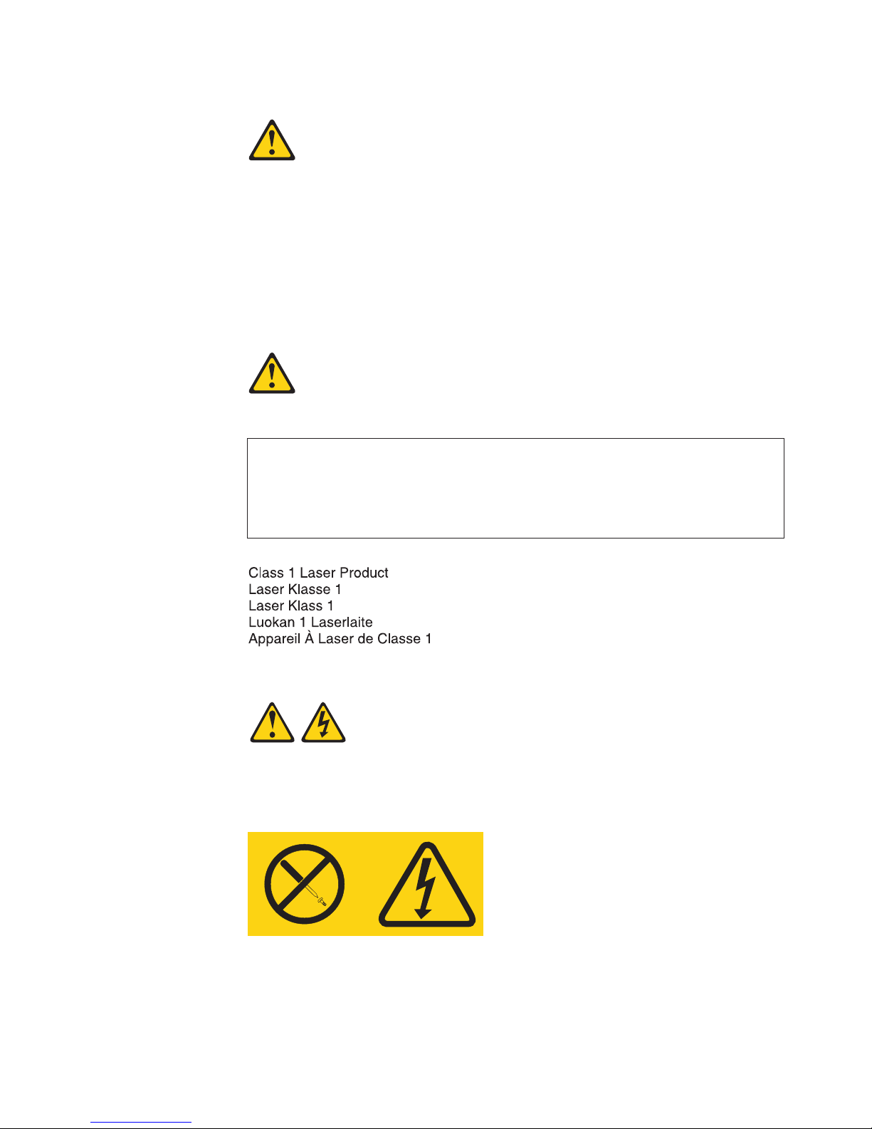
Statement 3:
CAUTION:
When laser products (such as CD-ROMs, DVD drives, fiber optic devices, or
transmitters) are installed, note the following:
v Do not remove the covers. Removing the covers of the laser product could
result in exposure to hazardous laser radiation. There are no serviceable
parts inside the device.
v Use of controls or adjustments or performance of procedures other than
those specified herein might result in hazardous radiation exposure.
DANGER
laser products contain an embedded Class 3A or Class 3B laser
Some
diode. Note the following.
Laser radiation when open. Do not stare into the beam, do not view directly
with optical instruments, and avoid direct exposure to the beam.
Class 1 Laser Product
Laser Klasse 1
Laser Klass 1
Luokan 1 Laserlaite
Appareil A Laser de Classe 1
Statement 8:
`
CAUTION:
Never remove the cover on a power supply or any part that has the following
label attached.
Hazardous voltage, current, and energy levels are present inside any
component that has this label attached. There are no serviceable parts inside
these components. If you suspect a problem with one of these parts, contact
a service technician.
Safety ix
Page 12
Statement 12:
CAUTION:
The following label indicates a hot surface nearby.
Statement 13:
DANGER
Overloading
a branch circuit is potentially a fire hazard and a shock hazard
under certain conditions. To avoid these hazards, ensure that your system
electrical requirements do not exceed branch circuit protection
requirements. Refer to the information that is provided with your device for
electrical specifications.
Statement 21:
CAUTION:
Hazardous energy is present when the blade is connected to the power
source. Always replace the blade cover before installing the blade.
x BladeCenter HT Type 8740 and 8750: Installation and User’s Guide
Page 13

Statement 29:
CAUTION:
This equipment is designed to permit the connection of the earthed conductor
of the dc supply circuit to the earthing conductor at the equipment. If this
connection is made, all of the following conditions must be met:
v This equipment shall be connected directly to the dc supply system
earthing electrode conductor or to a bonding jumper from an earthing
terminal bar or bus to which the dc supply system earthing electrode
conductor is connected.
v This equipment shall be located in the same immediate area (such as,
adjacent cabinets) as any other equipment that has a connection between
the earthed conductor of the same dc supply circuit and the earthing
conductor, and also the point of earthing of the dc system. The dc system
shall not be earthed elsewhere.
v The dc supply source shall be located within the same premises as this
equipment.
v Switching or disconnecting devices shall not be in the earthed circuit
conductor between the dc source and the point of connection of the
earthing electrode conductor.
Safety xi
Page 14

Statement 31:
DANGER
Electrical
current from power, telephone, and communication cables is
hazardous.
To avoid a shock hazard:
v Do not connect or disconnect any cables or perform installation,
maintenance, or reconfiguration of this product during an electrical
storm.
v Connect all power cords to a properly wired and grounded power
source.
v Connect to properly wired power sources any equipment that will be
attached to this product.
v When possible, use one hand only to connect or disconnect signal
cables.
v Never turn on any equipment when there is evidence of fire, water, or
structural damage.
v Disconnect the attached ac power cords, dc power sources, network
connections, telecommunications systems, and serial cables before you
open the device covers, unless instructed otherwise in the installation
and configuration procedures.
v Connect and disconnect cables as described in the following table when
installing, moving, or opening covers on this product or attached
devices.
To Connect: To Disconnect:
1. Turn OFF all power sources and
equipment to be attached to this product.
2. Attach all cables to the devices.
3. Attach signal cables to the connectors.
4. Attach power cords to power sources.
For dc systems, ensure correct polarity of
-48VDC connections: RTN is (+) and
-48VDC is (-). Earth ground should use a
two-hole lug for safety.
5. Turn ON all the power sources.
1. Turn OFF all power sources and
equipment to be attached to this product.
v For ac systems, remove all power
cords from the chassis power
receptables or interrupt power at the
ac power distribution unit.
v For dc systems, disconnect dc power
sources at the breaker panel or by
turning off the power source, then
remove the dc cables.
Remove the signal cables from the
2.
connectors.
3. Remove all cables from the devices.
xii BladeCenter HT Type 8740 and 8750: Installation and User’s Guide
Page 15
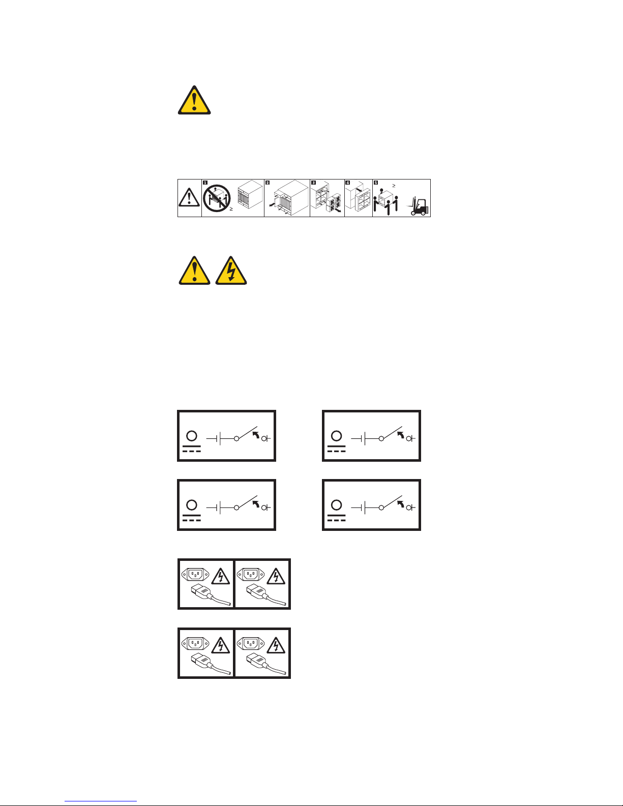
Statement 32:
CAUTION:
To avoid personal injury, before lifting the unit, remove all the blades, power
supplies, and removable modules to reduce the weight.
154 kg
Statement 33:
(340 lbs)
(4X)
(12X)
(5X)
(4X)
65.5 kg
(144 lbs)
or
CAUTION:
This device does not provide a power control button. Removing power supply
modules or turning off the server blades does not turn off the electrical
current supplied to the device. The device also might have more than one
power cord. To remove all electrical current from the device, ensure that all
power cords are disconnected from the power source.
BladeCenter HT Type 8740:
OFF
OFF
3
2
BladeCenter HT Type 8750:
3 1
2 4
OFF
OFF
1
4
Safety xiii
Page 16

Statement 34:
CAUTION:
To reduce the risk of electric shock or energy hazards:
v This equipment must be installed by trained service personnel in a
restricted-access location, as defined by the NEC and IEC 60950-1, First
Edition, The Standard for Safety of Information Technology Equipment.
v Connect the equipment to a properly grounded safety extra low voltage
(SELV) source. A SELV source is a secondary circuit that is designed so
that normal and single fault conditions do not cause the voltages to exceed
a safe level (60 V direct current).
v Incorporate a readily available approved and rated disconnect device in the
field wiring.
v See the specifications in the product documentation for the required
circuit-breaker rating for branch circuit overcurrent protection.
v Use copper wire conductors only. See the specifications in the product
documentation for the required wire size.
v See the specifications in the product documentation for the required torque
values for the wiring-terminal nuts.
xiv BladeCenter HT Type 8740 and 8750: Installation and User’s Guide
Page 17

Chapter 1. Introduction
The IBM® BladeCenter® HT Type 8740 and 8750 unit is a high-density,
high-performance rack-mounted blade server system. The BladeCenter HT unit
provides 12 bays for blade servers and other BladeCenter HT devices, integrating
common resources that are shared by the blade servers. The use of common
resources provides a small server-system footprint that contains high-performing
servers with minimal cabling. The BladeCenter HT unit has the following features:
v Hot-swap capability, which allows you to add, remove, or replace blade servers,
media trays, management modules, I/O modules, alarm panel modules,
multiplexer expansion modules, power modules, and fans without removing
power from the BladeCenter HT unit.
v A midplane that connects all BladeCenter HT components.
v A management module that functions as a systems-management processor.
There are two management-module bays.
v Power modules that provide redundant power for all BladeCenter HT
components. There are four power modules that operate in redundant pairs.
Each pair provides power to selected BladeCenter HT components.
v Fans that provide cooling for most BladeCenter HT components. There are three
fans connected to each power module on the front of the BladeCenter HT unit,
and four hot-swap fan modules on the rear of the BladeCenter HT unit.
v Four input/output (I/O) module bays that support external network interface
connections to network resources and other devices.
v Four high-speed input/output (I/O) module bays that support high-speed external
network interface connections to network resources and other devices.
v A media tray that contains two Universal Serial Bus (USB) version 2.0 ports that
can be used by any blade server, and two CompactFlash connectors that can be
used by the management module. There are two media-tray bays.
Installation and User’s Guide provides information about the following tasks:
This
v Defining and recording your BladeCenter HT network configuration information
v Installing and cabling the BladeCenter HT unit
v Installing basic BladeCenter HT unit optional devices:
– Media trays
– Management modules
– Management module interposers
– I/O modules
– I/O module interposers
– Power modules
– Blade servers
Performing basic troubleshooting of the BladeCenter HT unit
v
Packaged
with the Installation and User’s Guide are software CDs that help you to
configure and manage the BladeCenter HT unit. The CDs can be used with a USB
or network CD-ROM drive.
You can obtain up-to-date information about your BladeCenter HT Type 8740 and
8750 unit and other IBM server products at http://www.ibm.com/BladeCenter.
© Copyright IBM Corp. 2008 1
Page 18
Locating and recording BladeCenter HT unit information
Record information about your BladeCenter HT unit in the following table. You will
need this information for future reference.
Product name BladeCenter HT
Machine type _____________________________________________
Model number _____________________________________________
Serial number _____________________________________________
The serial number, machine type and model number are on labels on the top, front,
and rear of the chassis.
A set of blank labels comes with each BladeCenter HT unit. Record identifying
information on a label and place it on the BladeCenter HT unit top bezel, just above
the blade server. Do not place the label on the blade server itself or in any way
block the ventilation holes on the blade server.
User label
2 BladeCenter HT Type 8740 and 8750: Installation and User’s Guide
Page 19

Deployment scenarios
The IBM BladeCenter HT unit can be deployed to support a variety of networking
goals and environments, such as:
v Central Office (CO) environment
The IBM BladeCenter HT is ideally suited for network telecommunications
facilities or carrier-grade environments that require maximum equipment
operability. The BladeCenter HT Type 8740 (dc power) is intended to be installed
in a Common Bonding Network (or mesh network) as described in
GR-1089-CORE, Issue 4.
v Server consolidation
The IBM BladeCenter HT unit can be used by organizations with multiple server
locations that need to centralize or physically consolidate servers to increase
flexibility, reduce maintenance costs, and reduce human resources.
v e-business infrastructure
The IBM BladeCenter HT unit can be used by companies that need to deploy
new e-commerce and e-business applications and infrastructure quickly to
minimize time to market, while at the same time ensuring flexibility, scalability,
and availability.
v Enterprise infrastructure
The IBM BladeCenter HT unit can support an enterprise infrastructure through:
– File and print: For organizations with decentralized or departmental file and
print servers that need to reduce the cost of ownership, increase reliability,
and provide flexibility for growth.
– Collaboration: For customers needing a cost-effective way and reliable
corporate solution for e-mail, calendar, and other collaboration capabilities.
v High-performance computing
The IBM BladeCenter HT unit can be used by customers with compute-intensive
applications needing highly available clustered solutions to achieve significantly
higher degrees of scalability and performance, all managed at a low cost.
v Any location where the National Electric Code (NEC) applies.
The IBM BladeCenter HT unit can be in installed in any location where NEC
requirements are used.
Chapter 1. Introduction 3
Page 20

Features and specifications
The following table provides a summary of the features and specifications of the
BladeCenter HT unit. Depending on the model, some features might not be
available, or some specifications might not apply.
Media tray (on front):
v Minimum: One hot-swap media tray
v Maximum: Two hot-swap media trays
Each media tray consists of:
v Two internal CompactFlash slots
v Two USB v2.0 ports (output power:
500 mA maximum)
v Front system LED panel
bays (on front): Twelve
Blade
hot-swap blade server bays
Module bays (on front):
v Four hot-swap power-module bays
v Four hot-swap high-speed
I/O-module bays
v Four hot-swap I/O-module bays
v Two hot-swap management-module
bays
v Two hot-swap media trays
bays (on rear):
Module
v Two hot-swap multiplexer
expansion-module bays
v One hot-swap alarm panel module
bay
– Telco alarm connector
– Direct serial connector for blade
servers
– Rear system LED panel
Four hot-swap fan modules
v
Power modules:
BladeCenter HT Type 8740:
v Minimum: Two dc hot-swap power
modules that are configured for
redundant operation
v Maximum: Four dc hot-swap power
modules that provide redundancy to
all BladeCenter HT components
BladeCenter
HT Type 8750:
v Minimum: Two ac hot-swap power
modules that are configured for
redundant operation
v Maximum: Four ac hot-swap power
modules that provide redundancy to
all BladeCenter HT components
Note: The intra-building ports of the equipment or subassembly are suitable for connection to intra-building or unexposed wiring or
cabling only. The intra-building ports of the equipment or subassembly must not be metallically connected to interfaces that connect
to the outside plant (OSP) or its wiring. These interfaces are designed for use as intra-building interfaces only (type 2 or type 4 ports
as described in GR-1089-CORE, Issue 4) and require isolation from the exposed OSP cabling. The addition of primary protectors is
not sufficient protection in order to connect these interfaces metallically to OSP wiring.
Management module:
v Minimum: One hot-swap advanced
management module
v Maximum: Two hot-swap advanced
management modules: one active, one
hot stand-by
Redundant
cooling: Four hot-swap
fan-module bays (N+1 redundant)
Upgradeable microcode:
v Management-module firmware
v I/O-module firmware (not all I/O module
types)
v Blade server firmware
Security
features:
v Login password for remote connection
v Secure Sockets Layer (SSL) security for
remote management access
v ANSI T1.276 enhanced security
features
Predictive
Failure Analysis
®
(PFA)
alerts:
v Fans
v Blade-dependent features
(12 U):
Size
v Height: 533.40 mm (21 in. or 12 U),
minus 8 mm for clearance
v Depth:
– Without optional bezel: 617 mm
(24.29 in.)
– With optional bezel: 706 mm (27.80
in.)
Width: 442 mm (17.4 in.)
v
v Weight:
– Full configured weight with blade
servers: Approximately 158.8 kg (350
lb)
– Empty chassis without modules or
blade servers: Approximately 65.32
kg (144 lb)
Environment (per Telcordia GR-63-CORE):
v Operational:
– Altitude: -60 m to 1800 m (-197 ft to
6000 ft), 5° C to 40° C (41° F to 104° F):
– Altitude: 1800 m to 4000 m (6000 ft to
13000 ft) 5° C to 30° C (41° F to 86° F)
– Humidity: 5% to 85%
v Short term operational:
– Altitude: -60 m to 1800 m (-197 ft to
6000 ft), -5° C to 55° C (23° F to 131° F)
– Altitude: 1800 m to 4000 m (6000 ft to
13000 ft), -5° C to 45° C (23° F to 113°
F)
– Humidity: 5% to 90% not to exceed
0.024 water/kg of dry air
v Shipping/Storage:
– Unit off: -40° C to 70° C (-40° F to 158°
F), 30° C/hr maximum rate of change
– Humidity: Uncontrolled
– Acclimation of the system might be
required after a period of high-humidity
storage
Acoustics:
Declared sound power level: 7.8
bels, 25° C, sea level
Electrical input (N+N redundant):
BladeCenter HT Type 8740 input voltage (four
inputs at 60 A rating each):
v Minimum: -40 V dc
v Maximum: -72 V dc
v DC isolated
BladeCenter
HT Type 8750 input voltage (four
inputs at 16 A rating each):
v Minimum: 180 V ac
v Maximum: 265 V ac
v Sine-wave input (50/60 Hz single-phase)
output: Approximate heat output in
Heat
British thermal units (Btu) per hour:
v BladeCenter HT Type 8740:
– Minimum configuration: 4270 Btu per
hour (1251 watts)
– Maximum configuration: 19680 Btu per
hour (5766 watts)
v BladeCenter HT Type 8750:
– Minimum configuration: 4175 Btu per
hour (1223 watts)
– Maximum configuration: 21850 Btu per
hour (6400 watts)
4 BladeCenter HT Type 8740 and 8750: Installation and User’s Guide
Page 21

The BladeCenter HT components
The BladeCenter HT unit supports the following hot-swap components:
v Blade servers
v Media tray
v Advanced management modules
v I/O modules
v Power modules
v Fan modules
v Multiplexer expansion modules
v Alarm panel module
“Major components of the BladeCenter HT Type 8740 and 8750 unit” on page
See
11 for the location of each module. These modules supply common functions to the
blade servers that are installed in the blade bays in the front of the BladeCenter HT
unit.
The BladeCenter HT unit and the active management module make optional I/O
devices (USB devices, keyboard, video, and mouse) available to all the blade
servers, selected by any one blade server at a time.
Blade servers
The BladeCenter HT unit provides 12 bays for blade servers or other BladeCenter
HT devices. A blade server is a hot-swap, independent server with its own
processors, memory, storage, network controllers, operating system, and
applications. The blade server is installed in a bay in the BladeCenter HT unit and
shares power, fans, switches, and ports with other blade servers.
Media tray
The BladeCenter HT unit comes with one hot-swap media tray in media tray bay 1.
You can add a second media tray in media tray bay 2 to provide redundancy.
The media tray is a hot-swap module that provides two USB connectors for use by
the blade servers, error LEDs, an ambient air temperature sensor and a pressure
sensor for use by the advanced management module, and two CompactFlash bays.
Advanced management module
The BladeCenter HT unit comes with one hot-swap advanced management module
in management-module bay 1. You can add a second advanced management
module in management-module bay 2 to provide redundancy.
When installing an advanced management module into the BladeCenter HT
Note:
unit, an advanced management-module interposer must be installed into the
bay before installing the advanced management module.
The advanced management module is a hot-swap module that you use to configure
and manage BladeCenter HT components. See the User’s Guide that comes with
the advanced management module for more information.
Chapter 1. Introduction 5
Page 22

I/O modules
Power modules
The BladeCenter HT unit has eight hot-swap I/O-module bays that are compatible
with three types of I/O modules (see “BladeCenter HT components and LEDs” on
page 18 for the location of the I/O module bays). These bays can be used as
follows:
Notes:
1. When installing an I/O module into the BladeCenter HT unit, an I/O-module
interposer must be installed into the bay before installing the I/O module.
2. When installing a high-speed I/O module into the BladeCenter HT unit, a
high-speed I/O-module interposer tray with interposer card must be installed into
the bay before installing the high-speed I/O module.
The modules in I/O bays 1 through 4 can be either of the following types:
v
– Switch modules
– Bridge modules
– Passthrough modules
The modules in I/O bays 7 through 10 support high-speed I/O modules.
v
The BladeCenter HT unit is configured with two or four hot-swap power modules.
Fan modules
Power modules are required in bays 1 and 2, and they supply power to blade bays
1 through 6, media trays 1 and 2, management-module bays 1 and 2, and
I/O-module bays 1 through 4.
Power modules are required in power module bays 3 and 4 if you install blade
servers in blade bays 7 through 12 or if you install I/O modules in any of
I/O-module bays 7 through 10.
Each pair of power modules operates as a redundant pair. If either power module
fails, the remaining power module continues to supply power, but there is no
redundancy; the failed power module must be replaced as soon as possible.
The BladeCenter HT unit comes with four hot-swap fan modules for cooling
redundancy. The fan module speeds vary depending on the ambient air temperature
within the BladeCenter HT unit, which is reported by the media tray. If the ambient
temperature is 25°C (77°F) or below, the BladeCenter HT unit fan modules will run
at their minimum rotational speed, increasing their speed as required to control
internal BladeCenter HT temperature. If the ambient temperature is above 25°C
(77°F), the fan modules will run faster, increasing their speed as required to control
internal BladeCenter HT unit temperature. Each fan module contains two fans
operating as a pair in a series. If one fan fails, the remaining fan will run at full
speed and continue to cool the BladeCenter HT unit. Replace a failed fan module
as soon as possible, to restore cooling redundancy.
Attention: If more than two fan modules are removed or more than two fan
modules experience a double fan failure, the blade servers will shut down within 1
to 3 seconds.
Multiplexer expansion modules
The BladeCenter HT unit comes with two hot-swap multiplexer expansion modules
for redundancy. The multiplexer expansion module controls the USB connectors,
6 BladeCenter HT Type 8740 and 8750: Installation and User’s Guide
Page 23

video signal, console redirection, and status LEDs on the BladeCenter HT unit.
Replace a multiplexer expansion module as soon as possible, to restore
redundancy.
Alarm panel module
The BladeCenter HT unit comes with an alarm panel module. The alarm panel
provides telecom relays and LED alarm status with additional functionality of a
serial console through the serial port on each blade server in the chassis using an
external breakout cable.
The IBM BladeCenter HT Documentation CD
The IBM BladeCenter HT Documentation CD contains documentation for your
BladeCenter HT unit in Portable Document Format (PDF) and includes the IBM
Documentation Browser to help you find information quickly.
Hardware and software requirements
The IBM BladeCenter HT Documentation CD requires the following minimum
hardware and software:
v Microsoft® XP®, Windows® 2000, or Red Hat® Linux
v 100 MHz microprocessor
v 32 MB RAM
v Adobe Acrobat Reader 3.0 (or later) or xpdf, which comes with Linux operating
systems.
Using the Documentation Browser
Use the Documentation Browser to browse the contents of the CD, read brief
descriptions of the documents, and view documents, using Adobe Acrobat Reader
or xpdf. The Documentation Browser automatically detects the regional settings in
use in your system and presents the information in the language for that region (if
available). If a topic is not available in the language for that region, the
English-language version is displayed.
Use one of the following procedures to start the Documentation Browser:
v If Autostart is enabled, insert the CD into the CD drive. The Documentation
Browser starts automatically.
v If Autostart is disabled or is not enabled for all users, use one of the following
procedures:
– If you are using a Windows operating system, insert the CD into the CD drive;
and, click Start → Run. In the Open field, type
e:\win32.bat
where e is the drive letter of the CD drive, and click OK.
– If you are using a Red Hat Linux, insert the CD into the CD drive and run the
following command from the /mnt/cdrom directory:
sh runlinux.sh
Select your BladeCenter HT product from the Product menu. The Available Topics
list displays all the documents for your BladeCenter HT product. Some documents
might be in folders. A plus sign (+) indicates each folder or document that has
additional documents under it. Click the plus sign to display the additional
documents.
Chapter 1. Introduction 7
Page 24

When you select a document, a description of the document is displayed under
Topic Description. To select more than one document, press and hold the Ctrl key
while you select the documents. Click View Book to view the selected document or
documents in Acrobat Reader or xpdf. If you selected more than one document, all
the selected documents are opened in Acrobat Reader or xpdf.
To search all the documents, type a word or word string in the Search field and
click Search. The documents in which the word or word string appears are listed in
order of the most occurrences. Click a document to view it, and press Ctrl+F to use
the Acrobat search function, or press Alt+F to use the xpdf search function within
the document.
Click Help for detailed information about using the Documentation Browser.
Related documentation
In addition to this Installation and User’s Guide, the following related documentation
is provided in Portable Document Format (PDF) at http://www.ibm.com/systems/
support/
BladeCenter HT unit:
v BladeCenter HT Problem Determination and Service Guide
v BladeCenter HT 2-Post Rack Installation Instructions
v BladeCenter HT 4-Post Rack Installation Instructions
v IBM BladeCenter HT Advanced Management Module Interposer and Flex Cable
v BladeCenter HT Advanced Management Module Installation Guide
v BladeCenter HT Management Module User’s Guide
v BladeCenter HT Management Module Command-Line Interface Reference Guide
or on the IBM BladeCenter HT Documentation CD that comes with your
This document is in Portable Document Format (PDF) on the IBM Documentation
CD. It contains information to help you solve problems yourself, and it contains
information for service technicians.
This document is in Portable Document Format (PDF) on the IBM Documentation
CD. It contains instructions for installing the BladeCenter HT unit in a 2-post rack.
This document is in Portable Document Format (PDF) on the IBM Documentation
CD. It contains instructions for installing the BladeCenter HT unit in a 4-post rack.
Assembly Installation Instructions
This document provides the installation instructions and warranty information for
an IBM BladeCenter HT Advanced Management Module Interposer and Flex
Cable Assembly.
This document contains instructions for installing the advanced management
module in the BladeCenter HT unit and creating the initial configuration.
This document provides general information about the advanced management
module for your BladeCenter HT unit, including information about features, how
to configure the management module, and how to get help.
This document explains how to use the advanced management-module
command-line interface to directly access BladeCenter HT management functions
as an alternative to using the Web-based user interface. The command-line
interface also provides access to the text-console command prompt on each
blade server through a serial over LAN (SOL) connection.
8 BladeCenter HT Type 8740 and 8750: Installation and User’s Guide
Page 25

v Safety Information
This document contains translated caution and danger statements. Each caution
and danger statement that appears in the documentation has a number that you
can use to locate the corresponding statement in your language in the Safety
Information document.
v Warranty and Support Information
This document contains information about the terms of the warranty and getting
service and assistance.
v IBM BladeCenter HT Redundant Media Tray Installation Instructions
This document provides the installation instructions and warranty information for
an IBM BladeCenter HT Redundant Media Tray.
v BladeCenter HT CompactFlash Module
This document provides the installation instructions and warranty information for
an IBM BladeCenter HT CompactFlash Module.
v IBM BladeCenter HT AC Power Supply Modules Installation Instructions
This document provides the installation instructions and warranty information for
an IBM BladeCenter HT AC Power Supply Module.
v IBM BladeCenter HT DC Power Supply Modules Installation Instructions
This document provides the installation instructions and warranty information for
an IBM BladeCenter HT DC Power Supply Module.
v IBM BladeCenter HT Interposer for Gb Switch/Bridge Bays and IBM BladeCenter
HT Interposer for Gb Switch/Bridge Bays with Interswitch Links (ISL) Installation
Instructions
This document provides the installation instructions and warranty information for
the IBM BladeCenter HT Interposer for Gb Switch/Bridge Bays and the IBM
BladeCenter HT Interposer for Gb Switch/Bridge Bays with Interswitch Links
(ISL).
v IBM BladeCenter HT Interposer for HS Switch Bay Installation Instructions
This document provides the installation instructions and warranty information for
an IBM BladeCenter HT Interposer for HS Switch Bay.
v IBM BladeCenter HT Bezel Installation Instructions
This document provides the installation instructions and warranty information for
the IBM BladeCenter HT Bezel option.
v IBM BladeCenter HT Bezel Filter 4-Pack Option
This document provides warranty information for the IBM BladeCenter HT Bezel
Filter 4-Pack Option.
Additional documents might be included on the IBM BladeCenter HT Documentation
CD.
Depending on your BladeCenter HT product, additional documentation might be
included on the IBM BladeCenter HT Documentation CD.
To check for updated documentation and technical updates, complete the following
steps.
Note: Changes are made periodically to the IBM Web site. The actual procedure
might vary slightly from what is described in this document.
1. Go to http://www.ibm.com/systems/support/.
2. Under Product support, click BladeCenter.
Chapter 1. Introduction 9
Page 26

3. Under Popular links, click Publications lookup.
4. From the Product family menu, select BladeCenter HT.
5. From the Type menu, select 8740 or 8750 and click Continue.
Notices and statements in this document
The caution and danger statements in this document are also in the multilingual
Safety Information document, which is on the IBM BladeCenter HT Documentation
CD. Each statement is numbered for reference to the corresponding statement in
the Safety Information document.
The following notices and statements are used in this document:
v Note: These notices provide important tips, guidance, or advice.
v Important: These notices provide information or advice that might help you avoid
inconvenient or problem situations.
v Attention: These notices indicate possible damage to programs, devices, or
data. An attention notice is placed just before the instruction or situation in which
damage could occur.
v Caution: These statements indicate situations that can be potentially hazardous
to you. A caution statement is placed just before the description of a potentially
hazardous procedure step or situation.
v Danger: These statements indicate situations that can be potentially lethal or
extremely hazardous to you. A danger statement is placed just before the
description of a potentially lethal or extremely hazardous procedure step or
situation.
10 BladeCenter HT Type 8740 and 8750: Installation and User’s Guide
Page 27
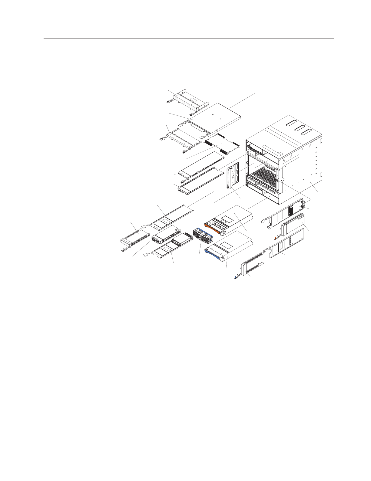
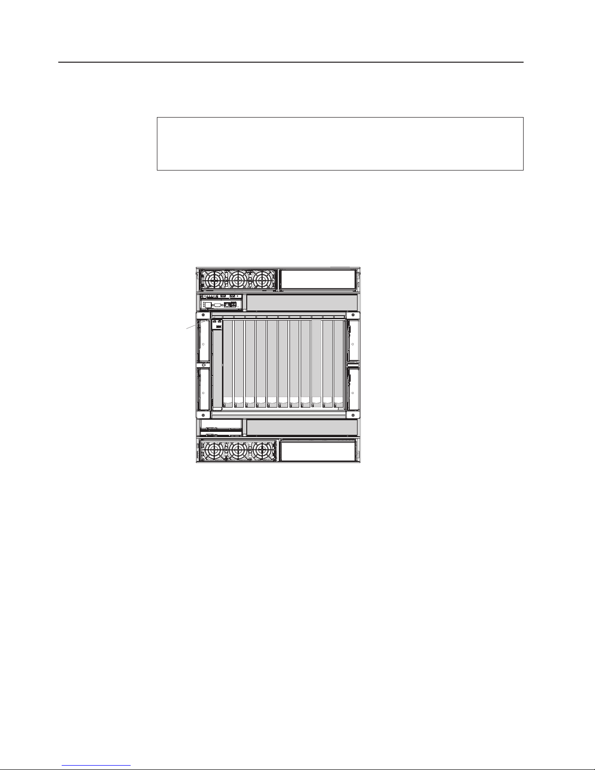
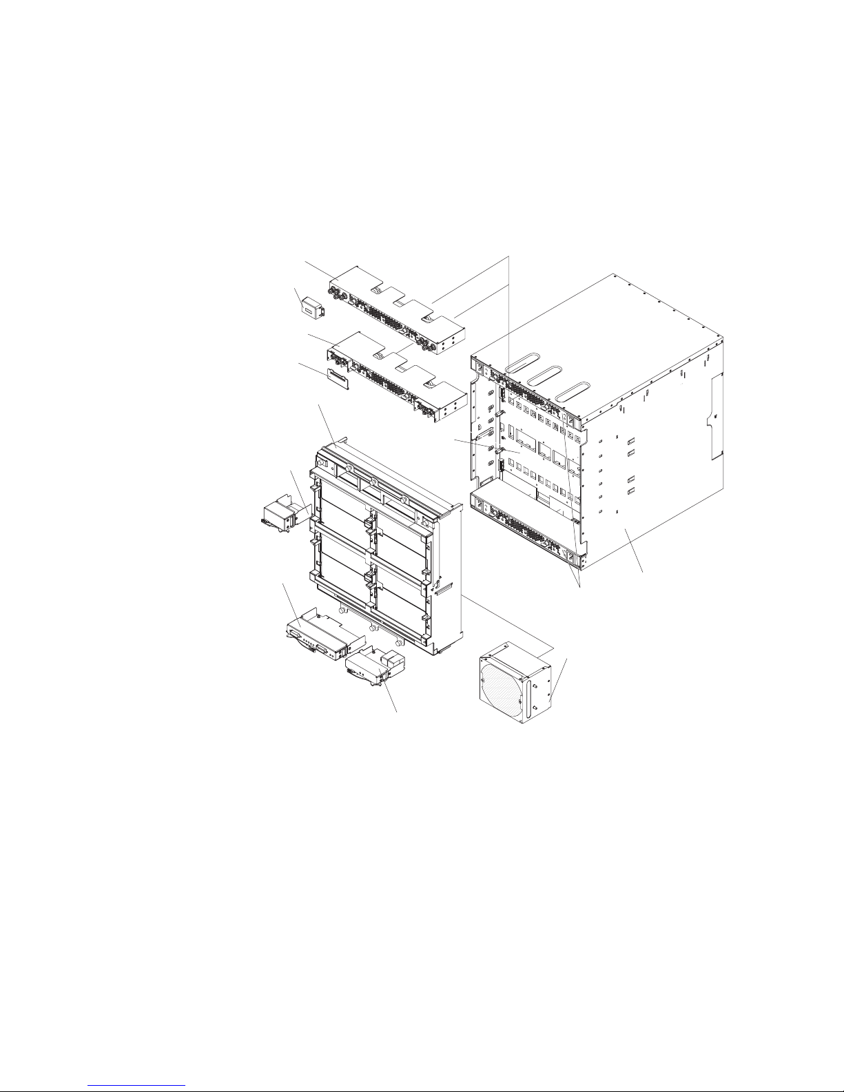
Major components of the BladeCenter HT Type 8740 and 8750 unit
The following illustrations show the locations of the major components in the
BladeCenter HT unit.
Front view
Management
module filler
Double height filler for
the high-speed
I/O-module bay
High-speed interposer
tray
Single height filler for
the high-speed
I/O-module bay
Management module
filler tray
High-speed
switch-module
interposer
Media tray
Media tray
filler
Blade filler
Power module
Chassis
I/O module
interposer
I/O module
Management
module
Management
module
interposer
Fan pack
Power module
filler
I/O filler tray
I/O module filler
Chapter 1. Introduction 11
Page 28
Rear view
Notes:
1. The BladeCenter HT unit comes with two dc power boxes or two ac power
boxes. The power boxes cannot be changed from the type that is already
installed.
2. If you have a dc power box in your BladeCenter HT unit, the type of dc terminal
cover you have might vary. Both types of dc terminal covers are shown in the
following illustration, but your BladeCenter HT unit has only one type.
DC power box
DC terminal
cover
DC power box
DC terminal
cover
Fan shuttle
Midplane
Network
clock-module
filler
Alarm panel
module
Chassis
AC power box
Fan module
Multiplexer expansion module
12 BladeCenter HT Type 8740 and 8750: Installation and User’s Guide
Page 29
Chapter 2. BladeCenter HT unit power, components, and
indicators
This section contains power requirements, component information, and it identifies
light-emitting diodes (LEDs) for the BladeCenter HT unit.
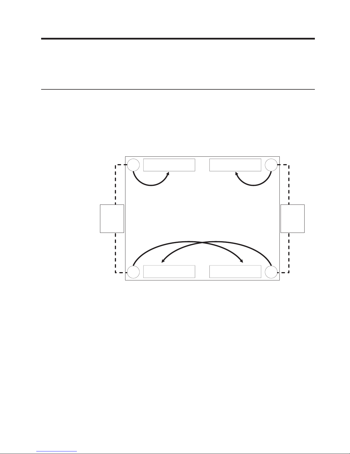
Supplying power to the BladeCenter HT unit
The BladeCenter HT unit does not have a power switch. The BladeCenter HT unit
has four power connectors; each powers a power module. As viewed from the rear
of the BladeCenter HT unit, power connector 1 (top-right connector) supplies power
to power-module bay 1, power connector 2 (bottom-left connector) supplies power
to power module 2, power connector 3 (top-left connector) supplies power to power
module 3, and power connector 4 (bottom-right connector) supplies power to power
module 4.
Power module 3IN 3
External
"B" power
source
(left side
from rear)
Power module 1
Power module 2Power module 4
IN 1
External
"A" power
source
(right side
from rear)
IN 4IN 2
Power modules 1 and 2 are redundant and provide power to blade bays 1 through
6, while power modules 3 and 4 are redundant and provide power to blade bays 7
through 12. To ensure power redundancy, a typical power configuration is to supply
power to power connectors 1 and 4 from one power source location, while
supplying power to power connectors 2 and 3 from another power source location.
Important: The release handles on the fan shuttle have a safety switch that
disables power output from the power boxes. If the release handles are not secured
to the chassis with the thumbscrews, the BladeCenter HT unit will not power on.
© Copyright IBM Corp. 2008 13
Page 30
Connecting the BladeCenter HT type 8740 to dc power:
The BladeCenter HT dc-power inputs are configured for dc isolated return (DC-I).
The dc RETURN (RTN) terminal or conductor is not connected to the equipment
frame or the grounding means of the equipment.
Attention: Only trained service personnel, other than IBM service technicians, are
authorized to make the connections to and disconnections from the dc power
source. IBM service technicians are not certified or authorized to install or remove
the dc power cables. The customer is responsible for ensuring that only trained
service personnel install or remove the dc power cables.
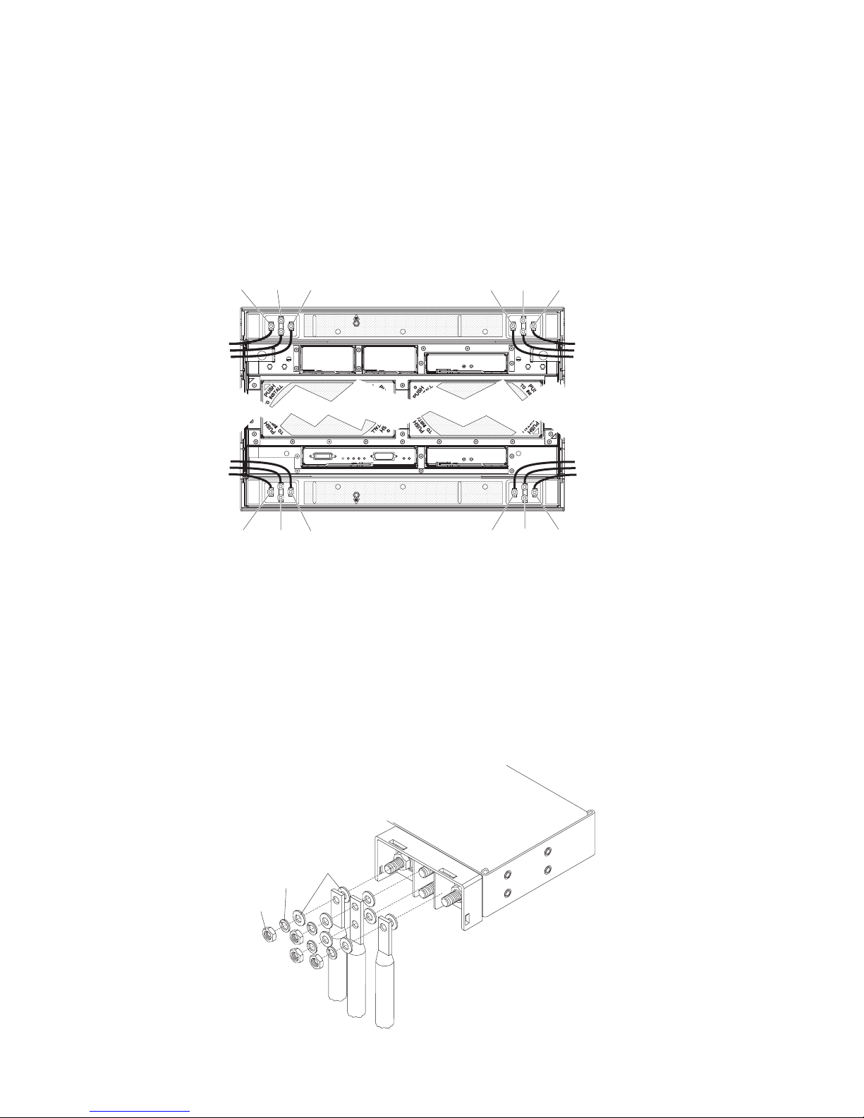
RTN GND -48v RTNGND-48v
RTN GND -48v
RTNGND-48v
The BladeCenter HT type 8740 has four dc-power terminal connectors. Each dc
terminal has four #M6 (0.25-inch) studs, one for -48 V dc, one for RETURN (RTN),
and two for connecting the safety ground wire. Each terminal has a terminal cover.
Remove the terminal cover before connecting cables to each terminal and reinstall
the terminal cover on each terminal before supplying power to the BladeCenter HT
unit. For more information on removing and installing a terminal cover, see
“Removing a dc terminal cover” on page 42 and “Installing a dc terminal cover” on
page 61.
There are two types of terminal covers, depending on date of manufacture. The
following illustrations show both types of terminal boxes for the two types of
terminal covers.
Flat washer
Split washer
Nut
(optional)
14 BladeCenter HT Type 8740 and 8750: Installation and User’s Guide
Page 31

Flat washer
(optional)
Split washer
Nut
When connecting a wire to each stud, install a flat washer (optional) on the stud,
install the wire, install a flat washer (optional), install a split washer and then install
the nut.
The following guidelines are provided for connecting a 60 A BladeCenter HT unit to
a -48 V dc power source:
v The power source must have a minimum of 80 A overcurrent protection. See
article 240, paragraph 3, table 310-16 of the National Electric Code for more
information about electrical wiring requirements.
v The overcurrent protective device or circuit breaker must be accessible to service
personnel to prevent the power from being turned on by someone other than the
technician servicing the BladeCenter HT unit.
v The BladeCenter HT unit has a dc wire rating of 4 AWG (circular mil area of
33100-52600) and rated 90 degree C.
The actual wire gauge and ring terminal will be determined by the current
Note:
draw and the length of wire run or as specified by the customer premises
guidelines.
v Flexible dc wiring is recommended to allow for minimum bend radius.
v The supply wiring to the power connectors must be terminated in UL recognized
insulated ring terminals, sized for a M6 stud, 4 AWG wire (circular mil area of
33100-52600) and a wire insulation diameter of 12.8 to 13.1 mm. An example of
this type of ring terminal is Amp Plasti-Grip type 52043–1 using Tyco Electronics
Hydraulic Crimping Tool part number 1490749–1.
v For NEBS compliance, the protective earthing conductor must use copper
conductors with a size minimum of 6 AWG (circular mil area of 20800–33100)
and must be terminated in a UL recognized two hole lug sized for a M6 stud.
Chassis ground studs are on 5/8-inch centers. An example of this type of two
hole lug is the Thomas and Betts part number 54205 using the Thomas and
Betts crimping tool model TBM-25S.
v Torque the wiring-terminal nuts to 1.5 newton-meters (13.3 inch-pounds)
For more information, see Statement 34 in “Safety” on page vii.
Chapter 2. BladeCenter HT unit power, components, and indicators 15
Page 32

Connecting the BladeCenter HT type 8750 to ac power:
The BladeCenter HT unit has four ac-power C20 input connectors. Two C20/C19
type ac jumper cords are supplied with the BladeCenter HT unit. To supply power to
the BladeCenter HT unit, connect one end of each power cord to a power
connector on the rear of the BladeCenter HT unit and the other end of each power
cord to a 200-240 volt 20 amp power distribution unit or appropriate electrical outlet.
An external Surge Protective Device (SPD) is not required at the ac-power input of
the BladeCenter HT unit.
The blade servers in the BladeCenter HT unit are connected to power but are not
turned on. After the BladeCenter HT unit has power, depending on the configuration
settings, the blade servers might have to be individually turned on.
Disconnecting power from the BladeCenter HT unit
You can shut down the BladeCenter HT unit by turning off the blade servers and
disconnecting the BladeCenter HT unit from the power source.
To disconnect power from the BladeCenter HT unit, complete the following steps:
1. Shut down each blade server. See the documentation that comes with your
blade servers for the procedure for shutting down the operating system.
2. Disconnect power from the BladeCenter HT unit.
Note: After you disconnect the BladeCenter HT unit from power, wait at least 5
seconds before you connect the BladeCenter HT unit to power again.
v BladeCenter HT type 8740:
a. Make sure the blade servers are powered off.
Statement 33:
CAUTION:
This device does not provide a power control button. Removing
power supply modules or turning off the server blades does not turn
off the electrical current supplied to the device. The device also
might have more than one power cord. To remove all electrical
current from the device, ensure that all power cords are
disconnected from the power source.
OFF
3
OFF
1
16 BladeCenter HT Type 8740 and 8750: Installation and User’s Guide
OFF
2
OFF
4
Page 33

Attention: Only trained service personnel, other than IBM service
technicians, are authorized to make the connections to and
disconnections from the -48 volt dc power source. IBM service
technicians are not certified or authorized to install or remove the -48 volt
power cable. The customer is responsible for ensuring that only trained
service personnel install or remove the -48 volt power cable.
b. Turn off the power source.
c. Remove the dc terminal cover for each power terminal. See “Removing a
dc terminal cover” on page 42 for more information.
Flat washer
Split washer
Nut
(optional)
d. Remove the nut, split washer, flat washer, and power cord from each
terminal post.
e. Remove the power cables.
BladeCenter HT type 8750:
v
a. Make sure the blade servers are powered off.
Statement 33:
CAUTION:
This device does not provide a power control button. Removing
power supply modules or turning off the server blades does not turn
off the electrical current supplied to the device. The device also
might have more than one power cord. To remove all electrical
current from the device, ensure that all power cords are
disconnected from the power source.
3 1
2 4
Chapter 2. BladeCenter HT unit power, components, and indicators 17
Page 34

b. Disconnect all power cords on the BladeCenter HT unit from the power
connectors.
BladeCenter HT components and LEDs
This section identifies the components and LEDs on the front and rear of the
BladeCenter HT unit.
Front view
This section identifies the components, controls, and LEDs on the front of the
BladeCenter HT unit.
Power module 1
Power module
bay 3
Media tray 1
Management
module 1
I/O module
bay 3
ESD
connector
I/O module
bay 2
Management
module bay 2
Media tray
bay 2
Power module 2
High-speed I/O
module bay 7
High-speed I/O
module bay 8
I/O module
bay 1
I/O module
bay 4
High-speed I/O
module bay 9
High-speed I/O
module bay 10
Power module
bay 4
18 BladeCenter HT Type 8740 and 8750: Installation and User’s Guide
Page 35

Power modules
The following illustration shows the LEDs on each power module.
Input power LED Power module error LED
Output power LED
Fan error LED
The LEDs on each power module indicate the condition of the power module and
fan pack.
Note: The orientation of the power module that is shown in the illustration is for
one of the top power modules. Modules in the bottom power-module bays
are rotated 180°.
v Input power LED: When this green LED is lit, the input from the external power
source connected to the power module is present and within specifications.
During typical operation, both the input power and output power LEDs are lit.
v Power-module error LED: When this amber LED is lit, a power-module failure
has occurred, and the power module is not operating within specifications.
v Fan error LED: When this amber LED is lit, a fan pack has failed and is not
operating within specifications.
v Output power LED: When this green LED is lit, the output from the power
module to the other components and blade servers is present and within
specifications. During typical operation, both the input power and output power
LEDs are lit.
Media tray
The media tray contains the following components:
Power on LED
Location LED
Critical system fault LED
Major system fault LED
Minor system fault LED
USB connectors
Media tray fault LED
v LED panel
The LEDs on the LED panel provide status information for your BladeCenter HT
unit.
Note: You can turn off the location LED through the advanced management
module.
– Power-on: When this green LED is lit, power is present in the BladeCenter
HT unit. When this LED is off, the power subsystem, the power module, or the
LED has failed.
Attention: If the power-on LED is off, it does not mean that electrical
current is not present in the BladeCenter HT unit. The LED might be
defective. To remove all electrical current from the BladeCenter HT unit, you
must disconnect all power cords from all power input connectors.
Chapter 2. BladeCenter HT unit power, components, and indicators 19
Page 36

– Location: When this blue LED is lit or flashing, it has been turned on by the
system administrator to aid in visually locating the BladeCenter HT unit. If a
blade server requires attention, the location LED on the blade server usually
will also be lit. After the BladeCenter HT unit has been located, you can have
the system administrator turn off the location LED.
– Critical system fault: When this LED is lit, the BladeCenter HT unit has a
critical system fault. A critical system fault is an error or event that is detected
by the system with a significant impact to the system. In this case, the system
cannot continue to operate or is operating in a non-redundant power
configuration or a non-redundant cooling configuration.
The color of this LED can be set to amber or red through the advanced
Note:
management module.
– Major system fault: When this LED is lit, the BladeCenter HT unit has a
major system fault. The system can continue to operate but might lose some
function and performance.
The color of this LED can be set to amber or red through the advanced
Note:
management module.
– Minor system fault: When this amber LED is lit, the BladeCenter HT unit has
a minor system fault. The system can continue to operate, usually without
noticeable loss of functionality or performance.
– Media tray fault: When this amber LED is lit, there is a fault on the media
tray. The system can continue to operate, usually without the use of the
components on the media tray.
USB connectors: Use these connectors to attach USB v2.0, or earlier,
v
compatible devices.
Management modules
See the management module documentation on the IBM BladeCenter HT
Documentation CD that comes with your BladeCenter HT unit for a description of
the LEDs and connectors on the module.
I/O modules
See the documentation that comes with each I/O module for a description of the
LEDs and connectors on the I/O module.
20 BladeCenter HT Type 8740 and 8750: Installation and User’s Guide
Page 37

Rear view
This section identifies the components, connectors, and LEDs on the rear of the
BladeCenter HT unit.
The following illustration shows a BladeCenter HT Type 8750 with ac-power
connectors.
ESD connector
Power connector 3
Network-clock
bay 1
Network-clock
bay 2
Power connector 1
Multiplexer expansion
module 1
Fan module 3
Fan module 1
Fan module 2Fan module 4
Multiplexer expansion
module 2
Power connector 2
Serial connector
Alarm panel module
Telco alarm connector
Power connector 4
ESD connector
The following illustration shows a BladeCenter HT Type 8740 with dc-power
connections.
RTN GND -48v RTNGND-48v
RTN GND -48v
RTNGND-48v
Chapter 2. BladeCenter HT unit power, components, and indicators 21
Page 38

Power connectors
Connect a power cord from each power connector to an appropriate power source.
See “Supplying power to the BladeCenter HT unit” on page 13 for more information.
Fan modules
Fan module orientation mark
Fan module fault LED
When the amber LED on a fan module is lit, an error has been detected in the fan
module.
Alarm panel module
Power-on LED
Location LED
Critical system fault LED
Major system fault LED
Minor system fault LED
FRU ready for removal LED
Alarm panel fault LED
Serial connector
Telco alarm connector
The alarm panel module provides telecom relays and LED alarm status with
additional functionality for access to a serial port on each blade server in the
chassis through an external breakout cable.
v Power-on: When this green LED is lit, power is present in the BladeCenter HT
unit. When this LED is off, the power subsystem, the power module, or the LED
has failed.
Attention: If the power-on LED is off, it does not mean that no electrical
current is present in the BladeCenter HT unit. The LED might be defective. To
remove all electrical current from the BladeCenter HT unit, you must disconnect
all power cords from the rear power connectors.
v Location: When this blue LED is lit or flashing, it has been turned on by the
system administrator, to aid in visually locating the BladeCenter HT unit. If a
22 BladeCenter HT Type 8740 and 8750: Installation and User’s Guide
Page 39

blade server requires attention, the location LED on the blade server usually will
also be lit. After the BladeCenter HT unit has been located, you can have the
system administrator turn off the location LED.
v Critical system fault: When this LED is lit, the BladeCenter HT unit has a
critical system fault. A critical system fault is an error or event that is detected by
the system with a significant impact to the system. In this case, the system
cannot continue to operate or is operating in a non-redundant power
configuration or a non-redundant cooling configuration.
Note: The color of this LED can be set to amber or red through the advanced
management module.
v Major system fault: When this LED is lit, the BladeCenter HT unit has a major
system fault. The system can continue to operate but may loose some
functionality and performance.
Note: The color of this LED can be set to amber or red through the advanced
management module.
v Minor system fault: When this amber LED is lit, the BladeCenter HT unit has a
minor system fault. The system can continue to operate, usually without
noticeable loss of functionality or performance.
v FRU ready for removal: When this blue LED is lit, it is safe to remove the
device from the BladeCenter HT unit.
v Alarm panel module fault: When this amber LED is lit, there is a fault on the
alarm panel module. The system can continue to operate, usually without the use
of the components on the alarm panel module.
v Serial connector: This DB60 connector provides direct access to the serial ports
on each of the 12 blade server bays. Use this connector to attach the optional
serial port breakout cable and connect up to 12 local consoles. See the
documentation that comes with your blade server to determine if it supports this
cable.
v Telco alarm connector: The alarm panel module provides one DB15 connector
(male) for critical, major, and minor telco alarms. Each of the alarms has a relay
that enables multiple system alarm indicators to be daisy-chained together. The
following table shows the pinouts for the alarm panel interface connector.
Pin # Description Input/Output signal
1 Minor alarm reset + Input
2 Minor alarm reset - Input
3 Major alarm reset + Input
4 Major alarm reset - Input
5 Critical alarm normally open Output
6 Critical alarm normally closed Output
7 Critical alarm common Output
8 Minor alarm normally open Output
9 Minor alarm normally closed Output
10 Minor alarm common Output
11 Major alarm normally open Output
12 Major alarm normally closed Output
13 Major alarm common Output
Chapter 2. BladeCenter HT unit power, components, and indicators 23
Page 40

Pin # Description Input/Output signal
14 Reserved Reserved
15 Reserved Reserved
The electrical specifications for the alarm panel interface connector are as
follows:
– Outputs
- Voltage range: 0 V dc to -100 V dc (maximum current 0.3 A at 100 V dc)
- Current range: 0 A to 1 A (maximum voltage 30 V dc at 1 A)
- Worst-case VA: 1 A at -30 V dc (30 VA maximum) indefinitely
Inputs
–
- Voltage range: 0 V dc to -100 V dc (including transients)
- Differential input voltage: 3 V dc to 72 V dc
Reset input activation
–
Pulse width: 200 ms (minimum) to 300 ms
The reset input only resets the state of the relay contact. The chassis
Note:
alarm status does not change.
Multiplexer expansion module
FRU ready for removal LED
Multiplexer expansion module
fault LED
The multiplexer expansion module controls the USB connectors, video signals, and
management module connections to the blade servers. There are two information
LEDs on the multiplexer expansion module:
v FRU ready for removal: When this blue LED is lit, it is safe to remove the
device from the BladeCenter HT unit.
When removing the multiplexer expansion module, another multiplexer
Note:
expansion module must be installed in its place to maintain proper cooling
in the BladeCenter HT unit.
v Multiplexer expansion module fault: When this amber LED is lit, there is a
fault on the multiplexer module. The system can continue to operate, usually
without the use of the components on the multiplexer module.
24 BladeCenter HT Type 8740 and 8750: Installation and User’s Guide
Page 41

Chapter 3. Installing the BladeCenter HT unit and options
This chapter provides instructions for installing the BladeCenter HT unit into a rack
and adding optional devices to your BladeCenter HT unit. Some removal
instructions are provided, in case you have to remove one device to install another.
Installation checklist
Before you can use the BladeCenter HT unit, you must install and configure the
required components in the BladeCenter HT unit. If you have not already done so,
perform the activities on the following checklist:
__ 1. Set up the rack or cabinet in which you will install the BladeCenter HT unit.
See the documentation that comes with your rack and rack mounting kit.
__ 2. Connect an ESD wrist strap to the ESD connector on the BladeCenter HT
unit before removing or installing any components. See “Front view” on
page 18 and “Rear view” on page 21 for the ESD connector locations on
the BladeCenter HT unit.
__ 3. Remove any modules that come installed in the BladeCenter HT unit to
reduce the weight of the unit. See “Removing components from a
BladeCenter HT unit” on page 28 for instructions.
__ 4. Install the BladeCenter HT unit into the rack. See the BladeCenter HT
4-Post Rack Installation Instructions or BladeCenter HT 2-Post Rack
Installation Instructions.
__ 5. Reinstall the removed modules in the BladeCenter HT unit. See “Installing
components into a BladeCenter HT unit” on page 44 for instructions.
Note: Make sure that the BladeCenter HT unit has adequate power to
support all of the installed components. The BladeCenter HT unit
must contain either two or four power modules. See “The
BladeCenter HT components” on page 5 and “Supplying power to
the BladeCenter HT unit” on page 13 for more information.
__ 6. Install the required BladeCenter HT unit components.
__ 7. Supply power to the BladeCenter HT unit. See “Supplying power to the
BladeCenter HT unit” on page 13 for more information.
__ 8. Make sure that the latest level of firmware is installed on all of the
BladeCenter HT components. See http://www.ibm.com/systems/support/ for
additional information.
__ 9. Configure the management module in the BladeCenter HT unit. See the
BladeCenter HT Advanced Management Module Installation Guide that
comes with your management module for information and instructions.
__ 10. Determine the BladeCenter HT unit configuration settings, such as the IP
address, network address, and Wake on LAN settings. Record the
BladeCenter HT configuration setting information in Appendix A,
“BladeCenter HT management-module configuration worksheet,” on page
77. See the BladeCenter HT Management Module User’s Guide that comes
with your management module for instructions for configuring an IP
address.
__ 11. Configure the I/O modules in the BladeCenter HT unit. See the
documentation for your I/O modules for configuration information.
__ 12. Configure the blade servers. See the Installation and User’s Guide that
comes with your blade server for information and instructions.
© Copyright IBM Corp. 2008 25
Page 42

Installing the BladeCenter HT unit in a rack
Install the BladeCenter HT unit in a rack before you install any modules or blade
servers in the BladeCenter HT unit. Reduce the weight of your BladeCenter HT unit
by removing any blade servers, power modules, and fan modules that are
preinstalled. The fan shuttle must also be removed from the rear of the BladeCenter
HT unit. You can further reduce the weight of the BladeCenter HT unit by removing
any preinstalled media trays, management modules, and I/O modules. Lift handles
come with your BladeCenter HT unit. See the rack installation instructions for more
information on installing the lift handles. Instructions for installing a BladeCenter HT
unit in a 4-post rack are in the BladeCenter HT 4-Post Rack Installation Instructions
and instructions for installing a BladeCenter HT unit in a 2-post rack are in the
BladeCenter HT 2-Post Rack Installation Instructions that come with the
BladeCenter HT unit.
Installation guidelines
Before you install any modules or fillers in the BladeCenter HT unit, read the
following information:
v Read the safety information that begins on page vii and the guidelines in
“Handling static-sensitive devices” on page 27. This information will help you
work safely.
v Orange on a component or an orange label on or near a component indicates
that the component can be hot-swapped, which means that you can remove or
install the component while the BladeCenter HT unit is running. (Orange can also
indicate touch points on hot-swap components.) See the instructions for removing
or installing a specific hot-swap component for any additional procedures that
you might have to perform before you remove or install the component.
v You do not have to disconnect the BladeCenter HT unit from power to install or
replace any of the hot-swap modules in the BladeCenter HT unit. You must shut
down the operating system and turn off a blade server before you remove the
blade server, but you do not have to shut down the BladeCenter HT unit itself.
v Blue on a component indicates touch points where you can grip the component
to open and close a latch, or grab a component to remove it from or install it into
the BladeCenter HT unit.
v For a list of supported optional devices for the BladeCenter HT unit, see
http://www.ibm.com/servers/eserver/serverproven/compat/us/.
System reliability guidelines
To help ensure proper cooling and system reliability, make sure that the following
requirements are met:
v Each of the module bays on the BladeCenter HT unit has either a module or a
module filler installed.
v Each of the blade bays on the front of the BladeCenter HT unit has either a
blade server or a blade filler installed.
v Each of the drive bays in a blade server storage expansion unit has either a
hot-swap drive or a filler installed.
v A removed hot-swap module, blade server, or drive is replaced within 1 minute of
removal.
v Cables for the optional modules are routed according to the illustrations and
instructions in this document.
v A failed fan is replaced as soon as possible, to restore cooling redundancy.
26 BladeCenter HT Type 8740 and 8750: Installation and User’s Guide
Page 43

Handling static-sensitive devices
Attention: Static electricity can damage the BladeCenter HT unit and other
electronic devices. To avoid damage, keep static-sensitive devices in their
static-protective packages until you are ready to install them.
Electrostatic discharge (ESD) is the release of stored static electricity that can
damage electric circuits. Static electricity is often stored in your body and
discharged when you come in contact with an object with a different potential. Use
an ESD wrist strap and the ESD connectors on the BladeCenter HT unit. See
“Front view” on page 18 and “Rear view” on page 21 for the locations of the ESD
connectors on your BladeCenter HT unit. The ESD wrist strap safely channels the
electricity from your body to a proper ground (the BladeCenter HT unit). To work
properly, the wrist strap must have a good contact at both ends (touching your skin
at one end and connected to the ESD connector on the front or back of the
BladeCenter HT unit). Use an ESD wrist strap whenever you are working on the
BladeCenter HT unit and BladeCenter HT components.
To reduce the possibility of electrostatic discharge, observe the following
precautions:
v Use an ESD wrist strap whenever you are working on the BladeCenter HT unit
and BladeCenter HT components.
v Limit your movement. Movement can cause static electricity to build up around
you.
v Handle the device carefully, holding it by its edges or its frame.
v Do not touch solder joints, pins, or exposed printed circuitry.
v Do not leave the device where others can handle and damage it.
v While the device is still in its static-protective package, touch it to an unpainted
metal part of the BladeCenter HT unit or rack for at least 2 seconds. This drains
static electricity from the package and from your body.
v Remove the device from its package and install it immediately without setting it
down. If it is necessary to set down the device, put it back into its
static-protective package.
v Take additional care when you handle devices during cold weather. Heating
reduces indoor humidity and increases static electricity.
Chapter 3. Installing the BladeCenter HT unit and options 27
Page 44

Removing components from a BladeCenter HT unit
The following procedures are for removing components or optional devices from the
BladeCenter HT unit.
Removing a cable management tray
The cable management trays can be installed with or without the BladeCenter HT
bezel. To remove the cable management trays and the BladeCenter HT bezel, see
the IBM BladeCenter HT Bezel Installation Instructions for more information.
To remove a cable management tray that is installed without the BladeCenter HT
bezel, complete the following steps:
Upper cable
management tray
Thumb
screws
Thumb
screws
Lower cable
management tray
1. Read the safety information that begins on page vii and “Installation guidelines”
on page 26.
2. Hold the cable management tray with one hand and use a phillips-head
screwdriver to loosen the captured thumb screws that attach the cable
management tray to the BladeCenter HT unit.
3. Pull the cable management tray away from the BladeCenter HT unit.
4. Repeat these steps for the other cable management tray.
28 BladeCenter HT Type 8740 and 8750: Installation and User’s Guide
Page 45

Removing a power module
To remove a power module, complete the following steps.
1. Read the safety information that begins on page vii and “Installation guidelines”
on page 26.
3rd power
module
Handle
(open)
Power-module
filler
Handle
(open)
4th power
module
2. Open the power-module handle, using one of the following procedures:
v For a power module in one of the upper power-module bays, push the inner
handle release to the right; then, pull the handle up to the open position.
v For a power module in one of the lower power-module bays, push the inner
handle release to the left; then, pull the handle down to the open position.
3. Use the handle to pull the module out of the bay.
Chapter 3. Installing the BladeCenter HT unit and options 29
Page 46

Removing a blade server
Attention: Note the bay number. Reinstalling a blade server into a different bay
other than the one from which it was removed can have unintended consequences.
Some configuration information and update options are established according to
bay number.
To remove a blade server, complete the following steps.
Handle
(open)
Handle
(open)
Blade server
1. Read the safety information that begins on page vii and “Installation guidelines”
on page 26.
2. Shut down the blade-server operating system; then, shut down the blade server.
See the documentation that comes with your blade servers for the procedure to
shut down the operating system. Wait at least 30 seconds until the drives stop
spinning, before you proceed to the next step.
3. Move the two release handles to the open position. The blade server moves out
of the bay approximately 0.6 cm (0.25 inch).
4. Pull the blade server out of the bay.
30 BladeCenter HT Type 8740 and 8750: Installation and User’s Guide
Page 47

Removing a media tray
To remove a media tray, complete the following steps.
Media tray
1. Read the safety information that begins on page vii and “Installation guidelines”
on page 26.
2. Pull the media tray release handle to the open position. The media tray moves
out of the bay approximately 0.6 cm (0.25 inch).
3. Slide the media tray out of the bay.
Removing a CompactFlash module
To remove a CompactFlash module, complete the following steps.
Secondary connector
Media tray
Primary connector
1. Read the safety information that begins on page vii and “Installation guidelines”
on page 26.
2. Pull out the media tray from the BladeCenter HT unit so that the CompactFlash
connectors are accessible (see “Removing a media tray”).
Chapter 3. Installing the BladeCenter HT unit and options 31
Page 48

Button (out position)
Raised edge
Narrow guide slot
3. Press the release button next to the CompactFlash module that you are
removing. The release button extends from the media tray.
4. Press the release button again to eject the CompactFlash module from the
media tray.
If the release button for a CompactFlash module is in the out position,
Note:
press the release button to the in position before installing the media tray
into the BladeCenter HT unit.
32 BladeCenter HT Type 8740 and 8750: Installation and User’s Guide
Page 49

Removing an I/O module
To remove an I/O module or module filler, complete the following steps.
I/O module
Handle
(open)
1. Read the safety information that begins on page vii and “Installation guidelines”
on page 26.
2. Pull the release handle to the open position. The module moves out of the bay
approximately 0.6 cm (0.25 inch).
3. Slide the module out of the bay.
Chapter 3. Installing the BladeCenter HT unit and options 33
Page 50

Removing an I/O-module interposer
To remove an I/O-module interposer or tray, complete the following steps.
I/O filler tray
I/O bay filler
Handle
(open)
I/O module interposer
1. Read the safety information that begins on page vii and “Installation guidelines”
on page 26.
2. Remove the I/O module or filler from the I/O-module bay (see “Removing an I/O
module” on page 33).
3. Pull the interposer release handle to the open position. The interposer moves
out of the bay approximately 0.6 cm (0.25 inch).
4. Slide the interposer out of the bay.
34 BladeCenter HT Type 8740 and 8750: Installation and User’s Guide
Page 51

Removing a high-speed I/O module
To remove a high-speed switch module or module filler, complete the following
steps.
Double-height
high-speed I/O
filler
High-speed
I/O module
1. Read the safety information that begins on page vii and “Installation guidelines”
on page 26.
2. Pull the module release handles to the open position. The module moves out of
the bay approximately 0.6 cm (0.25 inch).
3. Slide the module out of the bay.
High-speed
I/O bay 7
High-speed
I/O bay 8
Removing a high-speed I/O-module interposer tray
To remove an I/O-module interposer or interposer-filler tray, complete the following
steps.
High-speed
interposer tray
(upper)
High-speed
interposer tray
(lower)
1. Read the safety information that begins on page vii and “Installation guidelines”
on page 26.
2. Remove the high-speed I/O module or filler from the high-speed I/O-module bay
(see “Removing a high-speed I/O module”).
3. Pull the interposer-tray release handles to the open position. The interposer
moves out of the bay approximately 0.6 cm (0.25 inch).
4. Slide the interposer out of the bay.
High-speed
I/O bay 7
High-speed
I/O bay 8
Chapter 3. Installing the BladeCenter HT unit and options 35
Page 52

Removing a management module
To remove a management module or module filler, complete the following steps.
Management
module
Handle
(open)
1. Read the safety information that begins on page vii and “Installation guidelines”
on page 26.
2. Pull the module release handle to the open position. The module moves out of
the bay approximately 0.6 cm (0.25 inch).
3. Slide the module out of the bay.
36 BladeCenter HT Type 8740 and 8750: Installation and User’s Guide
Page 53

Removing a management-module interposer
To remove a management-module interposer or interposer-filler tray, complete the
following steps.
Management module
tray filler
Management module
filler
Management module interposer
Handle
(open)
1. Read the safety information that begins on page vii and “Installation guidelines”
on page 26.
2. Remove the management module or filler from the management-module bay
(see “Removing a management module” on page 36).
3. Pull the management-module interposer or filler tray release handle to the open
position. The interposer moves out of the bay approximately 0.6 cm (0.25 inch).
4. Slide the interposer out of the bay.
Chapter 3. Installing the BladeCenter HT unit and options 37
Page 54

Removing a network clock filler
To remove a network clock filler, complete the following steps.
Network
clock-module filler
Release handle
(open)
1. Read the safety information that begins on page vii and “Installation guidelines”
on page 26.
2. Pull the release handle to the open position. The filler moves out of the bay
approximately 0.6 cm (0.25 inch).
3. Slide the filler out of the bay.
38 BladeCenter HT Type 8740 and 8750: Installation and User’s Guide
Page 55

Removing a multiplexer expansion module
To remove a multiplexer expansion module, complete the following steps.
Multiplexer
expansion
module
Release handle
open
1. Read the safety information that begins on page vii and “Installation guidelines”
on page 26.
2. Pull the release handle to the open position. The module moves out of the bay
approximately 0.6 cm (0.25 inch).
3. Slide the module out of the bay.
Chapter 3. Installing the BladeCenter HT unit and options 39
Page 56

Removing an alarm panel module
To remove an alarm panel module or module filler, complete the following steps.
Release handle
open
Alarm
panel module
1. Read the safety information that begins on page vii and “Installation guidelines”
on page 26.
2. Pull the release handle to the open position. The module moves out of the bay
approximately 0.6 cm (0.25 inch).
3. Slide the module out of the bay.
40 BladeCenter HT Type 8740 and 8750: Installation and User’s Guide
Page 57

Removing a fan module
To remove a fan module, complete the following steps.
Release levers
Fan module
1. Read the safety information that begins on page vii and “Installation guidelines”
on page 26.
Fan module 3
orientation mark
Push down on
these levers to
partially eject
this fan.
Push down on
these levers to
partially eject
this fan.
Fan module 1
orientation mark
Fan module 4
orientation mark
Push down on
these levers to
partially eject
this fan.
Push down on
these levers to
partially eject
this fan.
Fan module 2
orientation mark
Attention: While the BladeCenter HT is operating, only one fan module should
be removed at a time. Removing two fan modules might cause the BladeCenter
HT unit to overheat.
2. If a shipping block is installed below the release levers, complete the following
steps:
When the BladeCenter HT unit is shipped, each fan module has a
Note:
shipping block installed below the release lever that is on the same side
as the fan module orientation mark.
Chapter 3. Installing the BladeCenter HT unit and options 41
Page 58

Release lever
Shipping block
Screw
a. Remove the phillips-head screw that attaches the shipping block to the
BladeCenter HT unit.
b. Pull the shipping block away from the BladeCenter HT unit. Place the
shipping block and screw in a safe place.
When the BladeCenter HT unit is shipped, a shipping block must be
Note:
installed for each fan module. The shipping block is installed below
the release lever that is on the same side as the fan module
orientation mark.
Press down on the release levers on either side of the fan module you are
3.
removing. The module moves out of the bay approximately 0.6 cm (0.25 inch).
4. Pull the fan module out of the bay.
Removing a dc terminal cover
There are two types of terminal covers, depending on the date of manufacture. The
following illustrations show both types of terminal covers.
DC terminal
cover
Locking tabs
42 BladeCenter HT Type 8740 and 8750: Installation and User’s Guide
Page 59

DC terminal
cover
Screws
To remove a dc terminal cover from an IBM BladeCenter HT type 8740, complete
the following steps.
1. Read the safety information that begins on page vii and “Installation guidelines”
on page 26.
2. Shut down each blade server. See the documentation that comes with your
blade servers for the procedure for shutting down the operating system.
3. Turn off the power source.
Note: After you disconnect the BladeCenter HT unit from power, wait at least 5
seconds before you connect the BladeCenter HT unit to power again.
4. If your terminal cover is attached to the dc power box with two phillips-head
screws, remove the screws.
5. Pull the terminal cover away from the BladeCenter HT unit.
Removing the fan shuttle
To remove the shuttle, complete the following steps.
Fan shuttle
Captive
thumb
screws
Captive screws
(4 places)
Chassis
Release handle
(open)
Chapter 3. Installing the BladeCenter HT unit and options 43
Page 60

1. Read the safety information that begins on page vii and “Installation guidelines”
on page 26.
2. Shut down the operating systems and turn off any blade servers in the
BladeCenter HT unit. See the documentation that comes with the blade server
for detailed instructions.
3. If the BladeCenter HT unit is connected to a power source, disconnect the
power from the BladeCenter HT unit and remove the power cables (see
“Disconnecting power from the BladeCenter HT unit” on page 16).
4. Disconnect the cables from the modules in the rear of BladeCenter HT unit.
5. Remove any of the following modules that are installed in the rear of the
BladeCenter HT unit:
v Fan modules (see “Removing a fan module” on page 41).
v Network clock fillers (see “Removing a network clock filler” on page 38).
v Multiplexer expansion modules (see “Removing a multiplexer expansion
module” on page 39).
v Alarm panel module (see “Removing an alarm panel module” on page 40).
Loosen the four captive thumb screws on the fan shuttle.
6.
7. Loosen the captive thumbscrews on the release handles, and pull the handles
to the open position. The fan shuttle moves out of the BladeCenter HT chassis
approximately 1.3 cm (0.5 inch).
Attention: Use your hands to hold the frame of the fan shuttle where the
fan-module bays are located. Do not use the release handles to hold the fan
shuttle.
8. While you support the fan shuttle with your hands, pull the fan shuttle out of the
BladeCenter HT chassis.
Installing components into a BladeCenter HT unit
The following procedures are for reinstalling components or installing optional
devices in the BladeCenter HT unit after the rack installation is complete.
44 BladeCenter HT Type 8740 and 8750: Installation and User’s Guide
Page 61

Installing the fan shuttle
To install the shuttle, complete the following steps.
Fan shuttle
Captive
Chassis
thumb
screws
Captive screws
(4 places)
Release handle
1. Read the safety information that begins on page vii and “Installation guidelines”
(open)
on page 26.
2. Make sure that no modules are installed in the fan shuttle and the release
handles on the shuttle are in the open position.
Attention: Use your hands to hold the frame of the fan shuttle where the
fan-module bays are located. Do not use the release handles to hold the fan
shuttle.
3. Orient the fan shuttle so that fan-module bays 1 and 3 are above fan-module
bays 2 and 4 (see “Rear view” on page 21).
4. Align the shuttle with the BladeCenter HT chassis and push the shuttle into the
chassis until it stops.
5. Push the release handles to the closed position. The shuttle moves back fully
into the BladeCenter HT chassis.
6. Tighten the four captive thumbscrews on the fan shuttle.
7. Tighten the captive thumbscrew on each release handle.
Important: The release handles have a safety switch that disables power
output from the power boxes. If the release handles are not secured to the
chassis with the thumbscrews, the BladeCenter HT unit will not power on.
8. Install any of the following modules that you removed from the rear of the
BladeCenter HT unit:
v Fan modules (see “Installing a fan module” on page 46).
v Network clock fillers (see “Installing a network clock filler” on page 47).
v Multiplexer expansion modules (see “Installing a multiplexer expansion
module” on page 48).
v Alarm panel module (see “Installing an alarm panel module” on page 49).
Chapter 3. Installing the BladeCenter HT unit and options 45
Page 62

9. Reconnect any cables that you disconnected from the modules in the rear of
the BladeCenter HT unit.
10. Reconnect the power to the BladeCenter HT unit (see “Supplying power to the
BladeCenter HT unit” on page 13).
11. Restart any blade servers that were shut down in the BladeCenter HT unit.
See the documentation that comes with each blade server for detailed
instructions.
Installing a fan module
To install a fan module, complete the following steps.
Release levers
Fan module
1. Read the safety information that begins on page vii and “Installation guidelines”
on page 26.
2. Orient the fan module to the selected fan-module bay.
Fan module orientation mark
Fan module fault LED
a. If you are installing a fan module in fan-module bay 1 or 2, orient the fan so
the orientation mark is at the bottom-right corner.
b. If you are installing a fan module in fan-module bay 3 or 4, orient the fan so
the orientation mark is at the top-left corner.
Slide the module into the bay until it stops.
3.
Make sure the release levers for the fan module return to a locked
Note:
46 BladeCenter HT Type 8740 and 8750: Installation and User’s Guide
position.
Page 63

4. If you are shipping the BladeCenter HT unit to another location, install the
shipping block that came with the BladeCenter HT unit.
When the BladeCenter HT unit is shipped, a shipping block must be
Note:
installed for each fan module. The shipping block is installed below the
release lever that is on the same side as the fan module orientation
mark.
Release lever
Shipping block
Screw
a. Orient the shipping block below the release lever on the same side as the
orientation mark on the fan module.
b. Push the shipping block into the slot below the release lever.
c. Install the phillips-head screw that attaches the shipping block to the
BladeCenter HT unit.
Installing a network clock filler
To install a network clock filler, complete the following steps.
Network
clock-module filler
Release handle
(open)
1. Read the safety information that begins on page vii and “Installation guidelines”
on page 26.
2. Make sure that the release handle on the filler is in the open position.
Chapter 3. Installing the BladeCenter HT unit and options 47
Page 64

3. Slide the filler into the module bay until it stops.
4. Push the release handle to the closed position.
Installing a multiplexer expansion module
To install a multiplexer expansion module or module filler, complete the following
steps.
Multiplexer
expansion
module
Release handle
open
1. Read the safety information that begins on page vii and “Installation guidelines”
on page 26.
2. Make sure that the release handle on the module is in the open position.
3. Slide the module into the module bay until it stops.
4. Push the release handle to the closed position.
48 BladeCenter HT Type 8740 and 8750: Installation and User’s Guide
Page 65

Installing an alarm panel module
To install an alarm panel module or module filler, complete the following steps.
Release handle
open
Alarm
panel module
1. Read the safety information that begins on page vii and “Installation guidelines”
on page 26.
2. Make sure that the release handle on the module is in the open position.
3. Slide the module into the module bay until it stops.
4. Push the release handle to the closed position.
Chapter 3. Installing the BladeCenter HT unit and options 49
Page 66

Installing a management-module interposer
To install a management-module interposer or filler tray, complete the following
steps.
Management module
tray filler
Management module
filler
Management module interposer
Handle
(open)
1. Read the safety information that begins on page vii and “Installation guidelines”
on page 26.
2. Remove the management module filler and management module tray filler (see
“Removing a management module” on page 36 and “Removing a
management-module interposer” on page 37).
3. Make sure that the release handle on the interposer is in the open position.
4. Slide the interposer into the module bay until it stops.
5. Push the interposer release handle to the closed position.
6. Install a management module or filler (see “Installing a management module” on
page 51).
50 BladeCenter HT Type 8740 and 8750: Installation and User’s Guide
Page 67

Installing a management module
To install a management module, complete the following steps.
Management
module
Handle
(open)
1. Read the safety information that begins on page vii and “Installation guidelines”
on page 26.
2. Remove the management-module filler, if one is installed (see “Removing a
management module” on page 36).
3. Remove the management module-interposer filler tray, if one is installed (see
“Removing a management-module interposer” on page 37).
4. Install the management module interposer, if it is not already installed (see
“Installing a management-module interposer” on page 50).
5. Make sure that the release handle on the module is in the open position.
6. Slide the module into the module bay until it stops.
7. Push the module release handle to the closed position.
8. Connect any cables to the module.
9. If the BladeCenter HT unit is connected to power, make sure that the OK LED
on the module is lit. If the management module is redundant, wait at least 45
minutes for the modules to copy the configuration data before making any
changes to the management module configuration.
Chapter 3. Installing the BladeCenter HT unit and options 51
Page 68

Installing an I/O-module interposer
Note: Before you install a new I/O-module interposer, read the documentation that
comes with the interposer for detailed instructions.
To install an I/O-module interposer, complete the following steps.
I/O filler tray
I/O bay filler
Handle
(open)
I/O module interposer
1. Read the safety information that begins on page vii and “Installation guidelines”
on page 26.
2. Remove the module filler and filler tray, if one is installed (see “Removing an I/O
module” on page 33 and “Removing an I/O-module interposer” on page 34).
3. Make sure that the release handle is in the open position.
4. Slide the module into the module bay until it stops.
5. Push the interposer release handle to the closed position.
6. Install an I/O module or filler (see “Installing an I/O module” on page 53).
52 BladeCenter HT Type 8740 and 8750: Installation and User’s Guide
Page 69

Installing an I/O module
The BladeCenter HT unit has 4 hot-swap I/O-module bays that are compatible with
three types of I/O modules (see “BladeCenter HT components and LEDs” on page
18 for the location of the I/O-module bays). Each I/O module requires an
I/O-module interposer to be installed first.
Note: Before you install a new I/O module, read the documentation that comes
with the module for detailed instructions.
To install an I/O module, complete the following steps.
I/O module
Handle
(open)
1. Read the safety information that begins on page vii and “Installation guidelines”
on page 26.
2. Remove the module filler, if one is installed (see “Removing an I/O module” on
page 33).
3. If not already installed, install an I/O-module interposer (see “Installing an
I/O-module interposer” on page 52).
4. Make sure that the release handle is in the open position.
5. Slide the module into the module bay until it stops.
6. Push the module release handle to the closed position.
7. Connect the cables to the module.
Chapter 3. Installing the BladeCenter HT unit and options 53
Page 70

Installing a high-speed I/O-module interposer tray
Note: Before you install a new high-speed I/O-module interposer, read the
documentation that comes with the interposer for detailed instructions.
To install a high-speed I/O-module interposer or tray, complete the following steps.
High-speed
interposer tray
(upper)
High-speed
interposer tray
(lower)
High-speed
I/O bay 7
High-speed
I/O bay 8
1. Read the safety information that begins on page vii and “Installation guidelines”
on page 26.
2. Remove the high-speed module or filler, if one is installed (see “Removing a
high-speed I/O module” on page 35).
3. Make sure that the release handles are in the open position.
4. Slide the interposer into the module bay until it stops.
5. Push the interposer-tray release handles to the closed position.
6. Install an I/O module or filler (see “Installing a high-speed I/O module” on page
55).
54 BladeCenter HT Type 8740 and 8750: Installation and User’s Guide
Page 71

Installing a high-speed I/O module
The BladeCenter HT unit has 4 hot-swap high-speed I/O-module bays (see “Major
components of the BladeCenter HT Type 8740 and 8750 unit” on page 11 for the
location of the I/O-module bays). Each high-speed I/O module requires a
high-speed I/O-module interposer to be installed first.
Notes:
1. Before you install a new high-speed I/O module, read the documentation that
comes with the module for detailed instructions.
2. Power modules must be present in all four power bays.
To install a high-speed I/O module or filler, complete the following steps.
Double-height
high-speed I/O
filler
High-speed
I/O module
High-speed
I/O bay 7
High-speed
I/O bay 8
1. Read the safety information that begins on page vii and “Installation guidelines”
on page 26.
2. Remove the module filler, if one is installed.
3. If not already installed, install a high-speed I/O-module interposer (see
“Installing a high-speed I/O-module interposer tray” on page 54).
4. Make sure that the release handles are in the open position.
5. Slide the module or filler into the module bay until it stops.
Notes:
a. If no high-speed I/O modules are installed in high-speed I/O bays 7 and 8,
install a double-height high-speed I/O filler into high-speed I/O bays 7 and 8.
b. If no high-speed I/O modules are installed in high-speed I/O bays 9 and 10,
install a double-height high-speed I/O filler into high-speed I/O bays 9 and
10.
c. If a high-speed I/O module is installed in high-speed I/O bay 7, install a
single-height high-speed I/O filler or another high-speed I/O module into
high-speed I/O bay 8.
d. If a high-speed I/O module is installed in high-speed I/O bay 9, install a
single-height high-speed I/O filler or another high-speed I/O module into
high-speed I/O bay 10.
6. Push the module release handles to the closed position.
7. Connect the cables to the module.
Chapter 3. Installing the BladeCenter HT unit and options 55
Page 72

Installing a CompactFlash module
To install a CompactFlash module, complete the following steps.
1. Read the safety information that begins on page vii and “Installation guidelines”
on page 26.
2. Pull out the media tray from the BladeCenter HT unit so that the CompactFlash
connectors are accessible (see “Removing a media tray” on page 31).
3. If you are replacing a CompactFlash module that is already installed, remove it
(see “Removing a CompactFlash module” on page 31).
Media tray
Primary connector
Secondary connector
Button (in position)
Raised edge
Narrow guide slot
4. Make sure the CompactFlash release buttons are pushed in.
5. Insert the CompactFlash module into the primary or secondary connector on the
media tray.
The sides of the CompactFlash module have guide slots. Insert the
Note:
CompactFlash module with the narrow guide slot positioned toward the
front of the media tray.
6. Install the media tray into the BladeCenter HT unit (see “Installing a media tray”
on page 57).
56 BladeCenter HT Type 8740 and 8750: Installation and User’s Guide
Page 73

Installing a media tray
To install a media tray, complete the following steps.
Media tray
1. Read the safety information that begins on page vii and “Installation guidelines”
on page 26.
2. Make sure that the media tray release lever is in the open position and the
CompactFlash release buttons are pushed into the in position.
Media tray
CompactFlash
release button
3. Slide the media tray into position until it stops and locks into place.
4. Rotate the media tray release lever to the closed position.
Chapter 3. Installing the BladeCenter HT unit and options 57
Page 74

Installing a power module
To install a power module, complete the following steps.
3rd power
module
Handle
(open)
Power-module
filler
Handle
(open)
4th power
module
1. Read the safety information that begins on page vii and “Installation guidelines”
on page 26.
2. Remove the module filler, if one is installed (see “Removing a power module” on
page 29).
3. Make sure that the handle on the power module is in the open position.
4. Orient the new power module to the selected power-module bay:
v For the upper power-module bays, the rear connector on the power module
must be facing down.
v For the lower power-module bays, the rear connector on the power module
must be facing up.
58 BladeCenter HT Type 8740 and 8750: Installation and User’s Guide
Page 75

Installing a blade server
Statement 21:
CAUTION:
Hazardous energy is present when the blade is connected to the power
source. Always replace the blade cover before installing the blade.
Attention: If this is the initial installation of a blade server in the BladeCenter HT
unit, you must configure the blade server by using the blade server
Configuration/Setup Utility program and install the blade server operating system.
See the documentation that comes with the blade server for instructions.
To install a blade server, complete the following steps.
Handle
(open)
Handle
(open)
Blade server
1. Read the safety information that begins on page vii and “Installation guidelines”
on page 26.
2. Select the bay for the blade server.
Notes:
a. Depending on the blade-server type and the optional devices that are
installed in it, one or more adjacent bays might be required.
b. When any blade server or device is in any blade bay 7 through 12, power
modules must be installed in all four power bays.
3. Remove the filler from the bay, if one is installed (see “Removing a blade
server” on page 30).
Attention: To help ensure proper cooling, performance, and system reliability,
do not operate the BladeCenter HT unit for more than 1 minute without either a
blade server or a blade filler installed in each blade bay.
4. Make sure that the two release handles are in the open position.
5. Slide the blade server into the bay until it stops.
6. Push the two release handles to the closed position.
7. Make sure that the blade server is receiving power. See the documentation that
comes with the blade server for instructions.
8. If you are installing a new blade server, write identifying information on one of
the user labels that come with the blade server; then, place the label on the
Chapter 3. Installing the BladeCenter HT unit and options 59
Page 76

BladeCenter HT unit top bezel, just above the blade server (see “Locating and
recording BladeCenter HT unit information” on page 2).
Important: Do not place the label on the blade server or in any way block the
ventilation holes on the BladeCenter HT unit bezel.
Installing the cable management trays without a bezel
The cable management trays can be installed with or without the BladeCenter HT
bezel option. If installing the BladeCenter HT bezel, see the IBM BladeCenter HT
Bezel Installation Instructions that comes with the BladeCenter HT bezel for more
information.
To install a cable management tray without a bezel, complete the following steps:
Upper cable
management tray
Thumb
screws
Thumb
screws
Lower cable
management tray
1. Read the safety information that begins on page vii and “Installation guidelines”
on page 26.
2. To install the upper cable management tray on the BladeCenter HT, complete
the following steps:
a. Orient the upper cable management tray so that the captive thumb screws
are oriented towards the blade-server bays.
b. Align the captive thumb screws with the screw holes above I/O-module bays
1 and 3.
c. Use a phillips-head screwdriver to screw the captured thumb screws into the
BladeCenter HT unit.
To install the lower cable management tray on the BladeCenter HT, complete
3.
the following steps:
a. Orient the lower cable management tray so that the captive thumb screws
are oriented towards the blade-server bays.
b. Align the captive thumb screws with the screw holes below I/O-module bays
2 and 4.
c. Use a phillips-head screwdriver to screw the captured thumb screws into the
BladeCenter HT unit.
60 BladeCenter HT Type 8740 and 8750: Installation and User’s Guide
Page 77

Installing a dc terminal cover
There are two types of terminal covers, depending on the date of manufacture. The
following illustrations show both types of terminal covers.
Locking tabs
DC terminal
cover
DC terminal
cover
Screws
To install a dc terminal cover on an IBM BladeCenter HT type 8740, complete the
following steps.
1. Read the safety information that begins on page vii and “Installation guidelines”
on page 26.
2. Make sure power has been disconnected from the BladeCenter HT unit. See
“Disconnecting power from the BladeCenter HT unit” on page 16 for more
information.
3. Turn off the power source.
Note: After you disconnect the BladeCenter HT unit from power, wait at least 5
seconds before you connect the BladeCenter HT unit to power again.
4. If your terminal cover has screw holes, orient the terminal cover so that it fits
over the dc power terminals and the screw holes on the terminal cover are
aligned with the screw holes on the dc power box. Install the two phillips-head
screws that attach the terminal cover to the power box.
5. If your terminal cover does not have screw holes, snap the cover into place so
that the locking tabs go into the slots on the side of the power terminals.
Chapter 3. Installing the BladeCenter HT unit and options 61
Page 78

Completing the installation
After you connect the cables to the modules and route the cables (see the cable
routing instructions that come with the rack, if necessary), complete the following
steps to start the BladeCenter HT unit and verify that it is working correctly:
1. Supply power to the BladeCenter HT unit (see “Supplying power to the
BladeCenter HT unit” on page 13).
2. Make sure that the following LEDs are lit and indicate that the device is working
correctly.
v Input power and output power LEDs on each power module
v OK LED on each management module
v OK LED on each I/O module
Make sure that the power-on LED on each blade server is lit, either steady or
3.
flashing slowly. See the documentation that comes with the blade servers for
the locations of the LEDs on the blade servers.
4. Make sure there are no fault or error LEDs lit on any of the modules. See
“BladeCenter HT components and LEDs” on page 18 for information about the
locations of the LEDs on the modules.
62 BladeCenter HT Type 8740 and 8750: Installation and User’s Guide
Page 79

Chapter 4. Configuration and networking guidelines
The BladeCenter HT components are configured and managed through a
management module. You can configure the management module and the
BladeCenter HT unit components through a local or remote connection and
management-module user interfaces or other system management tools. See your
management-module documentation for instructions for configuring the BladeCenter
HT unit.
Configuring the BladeCenter HT unit
General configuration of the BladeCenter HT unit and installed components is
performed through the management module. See the BladeCenter HT Management
Module User’s Guide and the BladeCenter HT Management Module Command-Line
Interface Reference Guide for your management module for information and
instructions. Some devices in the BladeCenter HT unit, such as I/O modules and
blade servers, might also require additional configuration. See the documentation
that comes with each device for information and instructions.
Configuring the management module
All management modules are preconfigured with the same static IP address. Yo u
can use the management module user interface to assign a new static IP address.
To establish connectivity, the management module attempts to use Dynamic Host
Configuration Protocol (DHCP) to acquire its initial IP address for the
management-module Ethernet port. If DHCP is not installed or is enabled and fails,
the management module uses the static IP address. Use the management module
to configure other BladeCenter HT component settings, such as user accounts,
DHCP, or Wake on LAN. See the documentation for your management module for
instructions.
Configuring I/O modules
You must install and configure at least one external (in-band) port on an Ethernet
switch module in I/O-module bay 1 or 2 to communicate with the Ethernet
controllers that are integrated in each blade server. See the documentation for your
management module for information about configuring external ports on I/O
modules. For I/O-device settings, see the documentation that comes with your I/O
device.
Note: If a pass-thru module is installed in I/O-module bay 1 or 2, you must
configure the external network switch to which the pass-thru module is
connected; see the documentation that comes with the external network
switch.
Configuring blade servers
To achieve blade server redundancy, you must configure the Ethernet controllers in
one or more blade servers for failover. When failover occurs on a blade server, the
secondary Ethernet controller takes over network communications, using the I/O
module that is associated with that controller. Install a pair of Ethernet switches in
I/O-module bays 1 and 2, and then configure them and your network infrastructure
so that they can direct traffic to the same destinations. You can also install a
pass-thru module that is connected to an external Ethernet switch in either or both
of these I/O-module bays. See the documentation that comes with your blade
server and operating system for instructions.
© Copyright IBM Corp. 2008 63
Page 80

BladeCenter HT networking guidelines
Make sure the network infrastructure is configured before you connect the
BladeCenter HT unit to a LAN switch or similar network device.
Each blade server has two independent Ethernet controllers, each with its own
MAC address and a dedicated 1000 Mbps link to one of the switch modules in
I/O-module bays 1 and 2. Switches that support Inter Switch Link (ISL) can be
configured to support switch to switch traffic on up to two internal switch link
interconnections between the peer switches. These ports can be configured as a
trunk group between these peer switches.
When installing a switch module that supports ISL, a switch-module
Note:
interposer that also supports ISL must be installed into the same I/O bay.
The management module has a separate internal 100 Mbps link to each switch.
These links are for internal management and control only. No data packets are
allowed to flow from application programs on the blade servers to the management
module over this path.
64 BladeCenter HT Type 8740 and 8750: Installation and User’s Guide
Page 81

Chapter 5. IBM Director
This chapter provides information about IBM Director, a workgroup-hardwaremanagement
With IBM Director, a network administrator can perform the following tasks:
v View the hardware configuration of remote systems, in detail.
v Monitor the usage and performance of critical components, such as
microprocessors, disks, and memory.
v Centrally manage individual or large groups of IBM and non-IBM servers,
desktop computers, workstations, and mobile computers on a variety of
platforms.
Director provides a comprehensive entry-level workgroup hardware manager. It
IBM
includes the following key features:
v Advanced self-management capabilities for maximum system availability.
v Multiple operating-system platform support, including Microsoft Windows 2000
Server, Windows Server 2003, Windows XP Professional, AIX, i5/OS, Red Hat
Linux, SUSE Linux, VMWare, and Novell NetWare. For a complete list of
operating systems that support IBM Director, see the IBM Director Compatibility
Document. This document is in PDF at http://www.ibm.com/servers/eserver/
xseries/systems_management/sys_migration/ibmdiragent.html.
6 to 8 weeks.
v Support for IBM and non-IBM servers, desktop computers, workstations, and
mobile computers.
v Support for systems-management industry standards.
v Integration into leading workgroup and enterprise systems-management
environments.
v Ease of use, training, and setup.
tool that you can use to centrally manage IBM servers.
It is updated every
Director also provides an extensible platform that supports advanced
IBM
BladeCenter HT tools that are designed to reduce the total cost of managing and
supporting networked systems. By deploying IBM Director, you can achieve
reductions in ownership costs through the following benefits:
v Reduced downtime
v Increased productivity of IT personnel and users
v Reduced service and support costs
more information about IBM Director, see the documentation on the IBM
For
Director CD that comes with the BladeCenter HT unit, the IBM Director Information
Center at http://publib.boulder.ibm.com/infocenter/eserver/rev2/topic/diricinfo/
fqm0_main.htm,
and the IBM Systems x Management Web page at
http://www.ibm.com/servers/eserver/xseries/systems_management/xseries_sm.html,
which presents an overview of IBM Systems Management and IBM Director.
© Copyright IBM Corp. 2008 65
Page 82

66 BladeCenter HT Type 8740 and 8750: Installation and User’s Guide
Page 83

Chapter 6. Shared BladeCenter HT resources
The BladeCenter HT unit provides resources that are available to most blade
servers at all times, such as power modules, cooling, system-management, and
network I/O modules; no user intervention is required. Some resources are
selectable for use by a single blade server at a time, such as the media tray or the
keyboard-video-mouse (KVM). You can select the resources for a blade server in
the following ways.
Attention: Do not switch ownership of the media tray to another blade server
while a transaction is taking place on an attached USB device, such as a USB
CD-ROM drive. The data might become corrupted. Make sure that activity lights on
the USB devices are not lit.
v Most blade servers have two selection buttons on the front of the blade server
CD
v You can use the management-module Web interface to enable or disable the
selection buttons on the blade servers and change ownership of the media tray
or the KVM (Blade Tasks → Remote Control).
The monitor that is attached to the management module shows the video output
from the blade server that is the current owner of the KVM. When there is no
actively selected video from any blade server, the video from blade server 12 is
routed to the management module. While the management module is restarting,
there is temporarily no current KVM owner. The video from blade server 12 is
displayed on the monitor briefly until the management module uses its NVRAM
values to reestablish ownership of the KVM and media tray. After that, the video
from the blade server that is the current KVM owner is displayed on the monitor.
– To switch the KVM to a specific blade server, press the
blade server.
– To switch the media tray to a specific blade server, press the
that blade server.
The
requesting it.
v On a keyboard that is directly attached to the management module, you can
press keyboard keys in the following sequence to switch KVM control between
blade servers:
NumLock NumLock blade_server_number Enter
Where blade_server_number is the two-digit number of the blade bay in which
the blade server is installed. When you use some keyboards, such as the
28L3644 (37L0888) keyboard, you must hold down the Shift key while you enter
this key sequence.
and
management module assigns the resource to the blade server that is
.
button on that
CD
button on
Note:
© Copyright IBM Corp. 2008 67
The KVM control key sequence does not change the ownership of the
media tray resources.
Page 84

It can take up to 20 seconds for the operating system in the switched-to blade
server to recognize the media tray or the KVM. If you install Microsoft Windows
2000 on a blade server while it is not the current owner of the media tray or the
KVM, the first time the blade server requests ownership after the operating system
has been installed, it can take up to 1 minute for the operating system to recognize
the devices (this is a one-time-only occurrence).
Note: The operating system in the blade server must provide USB support for the
blade server to recognize and use the media tray. The BladeCenter HT unit
uses USB for internal communication with these devices.
68 BladeCenter HT Type 8740 and 8750: Installation and User’s Guide
Page 85

Chapter 7. Solving problems
This chapter provides basic troubleshooting information to help you solve some
common problems that might occur while you are setting up your BladeCenter HT
unit.
If you cannot locate and correct a problem by using the information in this chapter,
see the Problem Determination and Service Guide for more information.
Diagnostic tools overview
The following tools are available to help you diagnose and solve hardware-related
problems:
v Troubleshooting tables
These tables list problem symptoms and steps to correct the problems. See
“Troubleshooting tables” on page 70 for more information.
v Diagnostic programs and error messages
The built-in self-test (BIST) program checks the BladeCenter HT unit during
startup and generates error messages if problems are found.
v Light path diagnostic LEDs
Use the light path diagnostic LEDs on the BladeCenter HT unit and the
BladeCenter HT components to identify system errors quickly. See “Light path
diagnostic LEDs” on page 74.
v Real Time Diagnostics
Real Time Diagnostics tests the major components of the BladeCenter HT unit,
including the management modules, I/O modules, removable-media drives, and
the blade servers. Real Time Diagnostics can be plugged into an existing IBM
Director environment or installed without IBM Director present. For
documentation and download information for Real Time Diagnostics, see
http://www.ibm.com/servers/eserver/xseries/systems_management/. See the
Problem Determination and Service Guide for more information.
v System event logs
The management module stores system events and can be accessed through
the management module user interface. See the User’s Guide that comes with
the management module for more information.
v Service data
The management module stores important hardware information that can be
accessed through the management module user interface. See the User’s Guide
that comes with the management module for more information.
© Copyright IBM Corp. 2008 69
Page 86

Troubleshooting tables
Use the troubleshooting tables to find solutions to problems that have identifiable
symptoms.
Note: The symptoms for monitor, keyboard, and mouse apply only to the devices
that are connected to the management module; they do not apply to the
remote console.
See the Problem Determination and Service Guide for more detailed information
about testing the BladeCenter HT unit. If you have run the diagnostic test programs
or if running the tests does not reveal the cause of problem, call for service.
Important: If diagnostic error messages are displayed that are not listed in the
Problem Determination and Service Guide, make sure that the latest level of
firmware code is installed in your BladeCenter HT unit.
If you have just added a new optional device and your system is not working,
complete the following steps before you use the troubleshooting tables:
1. Remove the device that you just added.
2. Run the diagnostic tests to determine whether the system is running correctly.
3. Update the firmware for the optional device
4. Reinstall the new device.
70 BladeCenter HT Type 8740 and 8750: Installation and User’s Guide
Page 87

Monitor or video problems
Note: These symptoms apply only to the monitor that is connected to the
management module; they do not apply to the remote console.
Some IBM monitors have their own self-tests. If you suspect a problem with your
monitor, see the documentation that comes with the monitor for instructions for
testing and adjusting the monitor.
v Follow the suggested actions in the order in which they are listed in the Action column until the problem
is solved.
v See the parts listing in the BladeCenter HT Problem Determination and Service Guide to determine which
components are customer replaceable units (CRU) and which components are field replaceable units
(FRU).
v If an action step is preceded by “(Trained service technician only),” that step must be performed only by a
trained service technician.
Symptom Action
The monitor is not working
1. Make sure that:
v The monitor is turned on and the brightness and contrast controls are
adjusted correctly.
v The monitor is connected to the active management module.
v The blade server that owns the KVM is turned on.
v The KVM is owned by a blade server that supports KVM.
Reseat the monitor cable.
2.
3. Call for service.
Power problems
v Follow the suggested actions in the order in which they are listed in the Action column until the problem
is solved.
v See the parts listing in the BladeCenter HT Problem Determination and Service Guide to determine which
components are customer replaceable units (CRU) and which components are field replaceable units
(FRU).
v If an action step is preceded by “(Trained service technician only),” that step must be performed only by a
trained service technician.
Symptom Action
The BladeCenter HT unit does
not start.
1. Make sure that:
a. All power cords are connected to a compatible power source and that the
power sources are working (see “Supplying power to the BladeCenter HT
unit” on page 13).
b. The input power and output power LEDs on the power modules are lit.
If you just installed an optional device, remove it. If the BladeCenter HT unit
2.
now starts, you might have installed more devices than the power modules
support. You might have to install power modules in power-module bays 3 and
4.
3. If the problem remains, see the BladeCenter HT Problem Determination and
Service Guide for more information.
Chapter 7. Solving problems 71
Page 88

Management module problems
v Follow the suggested actions in the order in which they are listed in the Action column until the problem
is solved.
v See the parts listing in the BladeCenter HT Problem Determination and Service Guide to determine which
components are customer replaceable units (CRU) and which components are field replaceable units
(FRU).
v If an action step is preceded by “(Trained service technician only),” that step must be performed only by a
trained service technician.
Symptom Action
Cannot connect to the
BladeCenter HT unit, using the
Web interface or Telnet
Cannot connect to the
BladeCenter HT unit after a
switchover to the redundant
management module
1. Make sure that:
v The network cable is connected to the Ethernet port on the active
management module.
v The network cable is not connected to the serial port on the management
module.
v The IP address or host name is correct. The default IP address is
192.168.70.125.
Reseat the management module.
2.
Note: Removing the active management module will cause an automatic
failover to the redundant management module, if one is installed.
3. Reset and reconfigure the management module (see the BladeCenter HT
Advanced Management Module Installation Guide for more information).
4. Call for service.
1. Make sure that:
v The redundant management module has been installed for at least 45
minutes to receive the transfer of data from the primary management
module.
v The network cable is connected to the Ethernet port on the active
(redundant) management module.
v The network cable is not connected to the serial port on the active
(redundant) management module.
v The IP address or host name is correct.
Reseat the management module.
2.
3. Reset and reconfigure the management module (see the BladeCenter HT
Advanced Management Module Installation Guide for more information).
4. Call for service.
72 BladeCenter HT Type 8740 and 8750: Installation and User’s Guide
Page 89

Fan module problems
v Follow the suggested actions in the order in which they are listed in the Action column until the problem
is solved.
v See the parts listing in the BladeCenter HT Problem Determination and Service Guide to determine which
components are customer replaceable units (CRU) and which components are field replaceable units
(FRU).
v If an action step is preceded by “(Trained service technician only),” that step must be performed only by a
trained service technician.
Symptom Action
A fan module is always
operating at full speed.
A fan module is not working.
1. Make sure that:
v The other fans are installed and working.
v At least one management module is installed, and it is active and working.
Reseat the fan module.
2.
3. Call for service.
1. Make sure that all power cords are connected to a compatible power source
and that the power source is working (see “Supplying power to the BladeCenter
HT unit” on page 13).
2. Reseat the fan module.
3. Call for service.
Media tray problems
v Follow the suggested actions in the order in which they are listed in the Action column until the problem
is solved.
v See the parts listing in the BladeCenter HT Problem Determination and Service Guide to determine which
components are customer replaceable units (CRU) and which components are field replaceable units
(FRU).
v If an action step is preceded by “(Trained service technician only),” that step must be performed only by a
trained service technician.
Symptom Action
A USB device is not recognized
by any blade server.
A CompactFlash module is not
recognized by the management
module.
1. Reseat the following components:
a. USB device
b. Media tray
Call for service.
2.
1. Reseat the following components:
a. CompactFlash module
b. Media tray
Call for service.
2.
Chapter 7. Solving problems 73
Page 90

Light path diagnostic LEDs
Light path diagnostic LEDs are a system of LEDs on the BladeCenter HT unit and
the BladeCenter HT components that can be used to diagnose system errors. If the
front or rear system-error LED on the BladeCenter HT unit is lit, one or more error
LEDs on the BladeCenter HT components also might be lit. These LEDs help to
identify the cause of the problem.
Diagnosing problems by using diagnostic LEDs
To identify the component that is causing the error, locate the lit error LED on that
component.
The following example shows how to use the LEDs to diagnose a system error:
1. Note that the BladeCenter HT system-fault LEDs are lit on the media tray LED
panel.
2. Locate the module or blade server that also has a lit error LED (see
“BladeCenter HT components and LEDs” on page 18 for the locations of error
LEDs; see the documentation that comes with your blade server for the
locations of error LEDs on the blade server).
v If the component is a module, replace the module.
v If the component is a blade server on which a system-error LED is lit, follow
the instructions in the documentation that comes with the blade server to
isolate and correct the problem.
Diagnostic LEDs
Use the following table to find solutions to problems that are identified by LEDs on
the front and rear BladeCenter HT system LED panels.
Lit LED Cause Action
BladeCenter HT system LED panels
Power-on When this green LED is lit, power is present in
the BladeCenter HT unit. When this LED is off,
the power subsystem, the ac power, or the
LED has failed, or the management module is
not present or not functioning.
Attention: If the power-on LED is off, it does
not mean that no electrical current is present in
the BladeCenter HT unit. The LED might be
burned out. To remove all electrical current
from the BladeCenter HT unit, you must
disconnect all power cords from all power
modules.
Location When this blue LED is lit, a condition has
occurred in the BladeCenter HT unit that has
caused the remote systems management to
identify the BladeCenter HT unit as needing
attention.
1. Make sure that the BladeCenter HT is
2. Reseat the following components:
Call for service.
3.
Look for any information or error LEDs on the
system LED panels, the modules, and the
blade servers in the BladeCenter HT unit, and
see the BladeCenter HT Problem
Determination and Service Guide for more
information.
connected to a compatible power supply
(see “Supplying power to the BladeCenter
HT unit” on page 13).
a. Media tray
b. Management module
c. Power modules
74 BladeCenter HT Type 8740 and 8750: Installation and User’s Guide
Page 91

Lit LED Cause Action
Critical system fault When this LED is lit, the BladeCenter HT unit
has a critical system fault. A critical system
fault is an error or event that is detected by the
1. Check the error log for messages.
2. Look for a lit error LED on the modules and
system with a significant impact to the system.
In this case, the system cannot continue to
operate or is operating in a non-redundant
power configuration or a non-redundant cooling
configuration.
Major system fault When this LED is lit, the BladeCenter HT unit
has a major system fault. The system can
continue to operate but might loose some
1. Check the error log for messages.
2. Look for a lit error LED on the modules and
function and performance.
Minor system fault When this LED is lit, the BladeCenter HT unit
has a minor system fault. The system can
continue to operate, usually without noticeable
Check the error log for the messages. Check
the LEDs on the BladeCenter HT unit and the
blade servers to isolate the component.
loss of function or performance.
Media tray fault
(This LED is only
There is an error with the media tray.
1. Reseat the media tray.
2. Call for service.
on the media tray
in the front of the
BladeCenter HT)
Alarm panel fault
(This LED is only
There is an error with the alarm panel module.
1. Reseat the alarm panel module.
2. Call for service.
on the alarm panel
module in the rear
of the BladeCenter
HT)
blade servers to locate a failing component:
v If the error LED is on a module, see the
documentation that comes with the
module.
v If the error LED is on a blade server, see
the documentation that comes with the
blade server.
blade servers to locate a failing component:
v If the error LED is on a module, see the
documentation that comes with the
module.
v If the error LED is on a blade server, see
the documentation that comes with the
blade server.
Chapter 7. Solving problems 75
Page 92

76 BladeCenter HT Type 8740 and 8750: Installation and User’s Guide
Page 93

Appendix A. BladeCenter HT management-module
configuration worksheet
Use the worksheets in this appendix to record the information for configuring the
BladeCenter HT unit through the management module. Information about using the
worksheet is provided in the Management Module User’s Guide for your
management module.
General settings
Management-module name
Contact name
Physical location
Clock settings
Login profiles
Login ID Password Authority level
R/O R/W
© Copyright IBM Corp. 2008 77
Page 94

External network interface (eth0)
DHCP __ DHCP with rollover to static
__ DHCP only
__ Static IP only
Host name
Static IP configuration (configure only if DHCP is disabled)
IP address ___.___.___.___
Subnet mask ___.___.___.___
Gateway IP address ___.___.___.___
Internal network interface (eth1)
Interface IP address ___.___.___.___
Subnet mask ___.___.___.___
Locally administered MAC address ___.___.___.___
78 BladeCenter HT Type 8740 and 8750: Installation and User’s Guide
Page 95

Alerts
Remote alert recipients
Receives critical alerts only
Status
Notification method __ SNMP over LAN
__ E-mail over LAN
__ IBM Director
Host name (or IP
address)
E-mail address
Global remote alert settings
Remote alerts retry limit
Delay between retries
Include event log with e-mail alerts __ Yes
__ No
Alerts to be monitored
Critical alerts Select all critical alerts
Hard disk drive
Multiple fan module failures
Power failure
Temperature
VRM failure
Multiple switch module failures
Invalid configuration
Major alerts Select all critical alerts
Single fan failure
Temperature
Voltage
KVM/media tray switching
failure
Redundant module failure
Minor alerts Power off
Inventory
Log 75% full
Appendix A. BladeCenter HT management-module configuration worksheet 79
Page 96

Network protocols
SNMP
SNMP agent __ Enable
__ Disable
SNMP traps __ Enable
__ Disable
Community name
Host name (or IP address)
SMTP
Host name (or IP address)
DNS
DNS __ Enable
__ Disable
DNS server IP address 1 ___.___.___.___
DNS server IP address 2 ___.___.___.___
DNS server IP address 3 ___.___.___.___
Security
Secure Socket Layer (SSL) __ Enabled
__ Disabled
Certificates __ Self-signed
__ Provided by a certificate authority
80 BladeCenter HT Type 8740 and 8750: Installation and User’s Guide
Page 97

Appendix B. Getting help and technical assistance
If you need help, service, or technical assistance or just want more information
about IBM products, you will find a wide variety of sources available from IBM to
assist you. This appendix contains information about where to go for additional
information about IBM and IBM products, what to do if you experience a problem
with your BladeCenter HT product or optional device, and whom to call for service,
if it is necessary.
Before you call
Before you call, make sure that you have taken these steps to try to solve the
problem yourself:
v Check all cables to make sure that they are connected.
v Check the power switches to make sure that the system and any optional
devices are turned on.
v Use the troubleshooting information in your system documentation, and use the
diagnostic tools that come with your system. Information about diagnostic tools is
in the Hardware Maintenance Manual and Troubleshooting Guide or Problem
Determination and Service Guide on the IBM Documentation CD that comes with
your system.
v Go to http://www.ibm.com/servers/eserver/support/BladeCenter to check for
information to help you solve the problem.
can solve many problems without outside assistance by following the
You
troubleshooting procedures that IBM provides in the online help or in the
documentation that is provided with your IBM product. The documentation that
comes with BladeCenter HT systems also describes the diagnostic tests that you
can perform. Most BladeCenter HT systems, operating systems, and programs
come with documentation that contains troubleshooting procedures and
explanations of error messages and error codes. If you suspect a software problem,
see the documentation for the software.
Using the documentation
Information about your IBM BladeCenter HT system and preinstalled software, if
any, or optional device is available in the documentation that comes with the
product. That documentation can include printed documents, online documents,
readme files, and help files. See the troubleshooting information in your system
documentation for instructions for using the diagnostic programs. The
troubleshooting information or the diagnostic programs might tell you that you need
additional or updated device drivers or other software. IBM maintains pages on the
World Wide Web where you can get the latest technical information and download
device drivers and updates. To access these pages, go to http://www.ibm.com/
servers/eserver/support/BladeCenter and follow the instructions. Also, some
documents are available through the IBM Publications Center at
http://www.ibm.com/shop/publications/order/.
Getting help and information from the World Wide Web
On the World Wide Web, the IBM Web site has up-to-date information about IBM
BladeCenter HT systems, optional devices, services, and support at
http://www.ibm.com/servers/eserver/support/BladeCenter.
© Copyright IBM Corp. 2008 81
Page 98

Software service and support
Through IBM Support Line, you can get telephone assistance, for a fee, with usage,
configuration, and software problems with BladeCenter HT products. For information
about which products are supported by Support Line in your country or region, see
http://www.ibm.com/services/sl/products/.
For more information about Support Line and other IBM services, see
http://www.ibm.com/services/, or see http://www.ibm.com/planetwide/ for support
telephone numbers. In the U.S. and Canada, call 1-800-IBM-SERV
(1-800-426-7378).
Hardware service and support
You can receive hardware service through IBM Services or through your IBM
reseller, if your reseller is authorized by IBM to provide warranty service. See
http://www.ibm.com/planetwide/ for support telephone numbers, or in the U.S. and
Canada, call 1-800-IBM-SERV (1-800-426-7378).
In the U.S. and Canada, hardware service and support is available 24 hours a day,
7 days a week. In the U.K., these services are available Monday through Friday,
from 9 a.m. to 6 p.m.
IBM Taiwan product service
IBM Taiwan product service contact information:
IBM Taiwan Corporation
3F, No 7, Song Ren Rd.
Taipei, Taiwan
Telephone: 0800-016-888
82 BladeCenter HT Type 8740 and 8750: Installation and User’s Guide
Page 99

Appendix C. Notices
This information was developed for products and services offered in the U.S.A.
IBM may not offer the products, services, or features discussed in this document in
other countries. Consult your local IBM representative for information on the
products and services currently available in your area. Any reference to an IBM
product, program, or service is not intended to state or imply that only that IBM
product, program, or service may be used. Any functionally equivalent product,
program, or service that does not infringe any IBM intellectual property right may be
used instead. However, it is the user’s responsibility to evaluate and verify the
operation of any non-IBM product, program, or service.
IBM may have patents or pending patent applications covering subject matter
described in this document. The furnishing of this document does not give you any
license to these patents. Yo u can send license inquiries, in writing, to:
IBM Director of Licensing
IBM Corporation
North Castle Drive
Armonk, NY 10504-1785
U.S.A.
Trademarks
INTERNATIONAL
BUSINESS MACHINES CORPORATION PROVIDES THIS
PUBLICATION “AS IS” WITHOUT WARRANTY OF ANY KIND, EITHER EXPRESS
OR IMPLIED, INCLUDING, BUT NOT LIMITED TO, THE IMPLIED WARRANTIES
OF NON-INFRINGEMENT, MERCHANTABILITY OR FITNESS FOR A
PARTICULAR PURPOSE. Some states do not allow disclaimer of express or
implied warranties in certain transactions, therefore, this statement may not apply to
you.
This information could include technical inaccuracies or typographical errors.
Changes are periodically made to the information herein; these changes will be
incorporated in new editions of the publication. IBM may make improvements and/or
changes in the product(s) and/or the program(s) described in this publication at any
time without notice.
Any references in this information to non-IBM Web sites are provided for
convenience only and do not in any manner serve as an endorsement of those
Web sites. The materials at those Web sites are not part of the materials for this
IBM product, and use of those Web sites is at your own risk.
IBM may use or distribute any of the information you supply in any way it believes
appropriate without incurring any obligation to you.
The following terms are trademarks of International Business Machines Corporation
in the United States, other countries, or both:
BladeCenter IBM (logo) System x
IBM ServerProven
Intel, Intel Xeon, Itanium, and Pentium are trademarks or registered trademarks of
Intel Corporation or its subsidiaries in the United States and other countries.
© Copyright IBM Corp. 2008 83
Page 100

Important notes
Microsoft, Windows, and Windows NT are trademarks of Microsoft Corporation in
the United States, other countries, or both.
UNIX is a registered trademark of The Open Group in the United States and other
countries.
Java and all Java-based trademarks and logos are trademarks of Sun
Microsystems, Inc. in the United States, other countries, or both.
Adaptec and HostRAID are trademarks of Adaptec, Inc., in the United States, other
countries, or both.
Linux is a trademark of Linus Torvalds in the United States, other countries, or both.
Red Hat, the Red Hat “Shadow Man” logo, and all Red Hat-based trademarks and
logos are trademarks or registered trademarks of Red Hat, Inc., in the United States
and other countries.
Other company, product, or service names may be trademarks or service marks of
others.
Processor speeds indicate the internal clock speed of the microprocessor; other
factors also affect application performance.
CD drive speeds list the variable read rate. Actual speeds vary and are often less
than the maximum possible.
When referring to processor storage, real and virtual storage, or channel volume,
KB stands for approximately 1000 bytes, MB stands for approximately 1 000 000
bytes, and GB stands for approximately 1 000 000 000 bytes.
When referring to hard disk drive capacity or communications volume, MB stands
for 1 000 000 bytes, and GB stands for 1 000 000 000 bytes. Total user-accessible
capacity may vary depending on operating environments.
Maximum internal hard disk drive capacities assume the replacement of any
standard hard disk drives and population of all hard disk drive bays with the largest
currently supported drives available from IBM.
Maximum memory may require replacement of the standard memory with an
optional memory module.
IBM makes no representation or warranties regarding non-IBM products and
services that are ServerProven®, including but not limited to the implied warranties
of merchantability and fitness for a particular purpose. These products are offered
and warranted solely by third parties.
IBM makes no representations or warranties with respect to non-IBM products.
Support (if any) for the non-IBM products is provided by the third party, not IBM.
Some software may differ from its retail version (if available), and may not include
user manuals or all program functionality.
84 BladeCenter HT Type 8740 and 8750: Installation and User’s Guide
 Loading...