

Page 1

BladeCenter T
Types 8720 and 8730
Planning and Installation Guide
GA27-4339-02
Page 2

Page 3

BladeCenter T
Types 8720 and 8730
Planning and Installation Guide
GA27-4339-02
Page 4

Note
Before using this information and the product it supports, read the general information in
Appendix C, “Notices,” on page 117.
Third Edition (August 2006)
© Copyright International Business Machines Corporation 2004, 2006. All rights reserved.
US Government Users Restricted Rights – Use, duplication or disclosure restricted by GSA ADP Schedule Contract
with IBM Corp.
Page 5

Preface
This guide is intended for anyone who plans for the physical installation and
configuration of an IBM® BladeCenter® T unit. This book is organized as follows and
should be used for these tasks:
v Use Chapter 1, “Introducing the BladeCenter T units,” on page 1 to understand
the overall purpose and usage of BladeCenter T units and blade servers.
v Use Chapter 2, “BladeCenter T unit components,” on page 13 to learn about the
physical components that make up a BladeCenter T unit.
v Use Chapter 3, “Deployment considerations,” on page 39 to learn about network
topology considerations and deployment considerations.
v Use Chapter 4, “Installation considerations,” on page 51 and Appendix A,
“Planning worksheets,” on page 89 to plan for the physical environment for
installing BladeCenter T units. This includes space, power, cooling, and cabling
requirements. The worksheets provide the basis for selecting the features and
options for each blade server, where the blade server is installed in a
BladeCenter T unit and a rack location for each BladeCenter T unit.
v Use Chapter 5, “Configuration considerations,” on page 75 and Appendix B,
“Configuration worksheets,” on page 101 to plan for the configuration of the:
– Management module
– I/O modules
– Fibre Channel switch modules
– Blade servers
© Copyright IBM Corp. 2004, 2006 iii
Page 6

iv BladeCenter T Types 8720 and 8730: Planning and Installation Guide
Page 7

Summary of changes
This document contains information previously presented in GA27-4339-01.
New and changed information for GA27-4339-02
In Chapter 4, Installation considerations, the following sections were updated to
reflect changes to part numbers for the Type 8730:
v Power distribution units
v Power connections
v Power layout examples
© Copyright IBM Corp. 2004, 2006 v
Page 8

vi BladeCenter T Types 8720 and 8730: Planning and Installation Guide
Page 9

Contents
Preface . . . . . . . . . . . . . . . . . . . . . . . . . . . . iii
Summary of changes . . . . . . . . . . . . . . . . . . . . . .v
New and changed information for GA27-4339-02 . . . . . . . . . . . . .v
Figures . . . . . . . . . . . . . . . . . . . . . . . . . . . .xi
Chapter 1. Introducing the BladeCenter T units . . . . . . . . . . . .1
Why choose the BladeCenter T technology? . . . . . . . . . . . . . .1
What the BladeCenter T unit offers . . . . . . . . . . . . . . . . .2
Reliability, availability, and serviceability . . . . . . . . . . . . . . .4
Features and specifications for the BladeCenter T Type 8720 . . . . . . .6
Features and specifications for the BladeCenter T Type 8730 . . . . . . .7
Why blade servers? . . . . . . . . . . . . . . . . . . . . . . .8
Blade server benefits . . . . . . . . . . . . . . . . . . . . . .8
Deployment scenarios . . . . . . . . . . . . . . . . . . . . . .9
Where to go for more information . . . . . . . . . . . . . . . . . .10
BladeCenter T documentation and operating system installation instructions 10
Hardware documentation . . . . . . . . . . . . . . . . . . .10
Redbooks publications . . . . . . . . . . . . . . . . . . . . .11
Operating system installation instructions . . . . . . . . . . . . . .12
Web sites . . . . . . . . . . . . . . . . . . . . . . . . . .12
Chapter 2. BladeCenter T unit components . . . . . . . . . . . . .13
Chassis . . . . . . . . . . . . . . . . . . . . . . . . . . .14
Front view . . . . . . . . . . . . . . . . . . . . . . . . .14
Rear view of the BladeCenter T unit . . . . . . . . . . . . . . . .15
Input/output connectors . . . . . . . . . . . . . . . . . . . . .16
2-way blade servers . . . . . . . . . . . . . . . . . . . . . . .18
Features and specifications for the HS20 Type 8843 for a non-NEBS/ETSI
environment . . . . . . . . . . . . . . . . . . . . . . . .19
Features and specifications for the HS20 Type 8843 for a NEBS/ETSI
environments . . . . . . . . . . . . . . . . . . . . . . . .20
4-way blade server . . . . . . . . . . . . . . . . . . . . . . .21
BladeCenter HS40 Type 8839 features and specifications for
non-NEBSI/ETSI environment . . . . . . . . . . . . . . . . .22
BladeCenter HS40 Type 8839 features and specifications for a NEBS/ETSI
environment . . . . . . . . . . . . . . . . . . . . . . . .23
Media tray . . . . . . . . . . . . . . . . . . . . . . . . . .24
Management module . . . . . . . . . . . . . . . . . . . . . . .25
Keyboard, video, and mouse module . . . . . . . . . . . . . . . . .28
LAN module indicators and input/output connectors . . . . . . . . . . .30
I/O modules . . . . . . . . . . . . . . . . . . . . . . . . . .32
Power modules for Type 8720 . . . . . . . . . . . . . . . . . . .35
Power modules for Type 8730 . . . . . . . . . . . . . . . . . . .36
Blowers . . . . . . . . . . . . . . . . . . . . . . . . . . .37
Blade servers . . . . . . . . . . . . . . . . . . . . . . . . .38
Blade server expansion options . . . . . . . . . . . . . . . . . .38
I/O expansion option . . . . . . . . . . . . . . . . . . . . .38
Expansion unit option . . . . . . . . . . . . . . . . . . . .38
Storage Expansion Unit option . . . . . . . . . . . . . . . .38
PCI I/O-expansion Unit option . . . . . . . . . . . . . . . .38
© Copyright IBM Corp. 2004, 2006 vii
Page 10

Chapter 3. Deployment considerations . . . . . . . . . . . . . . .39
Network topologies . . . . . . . . . . . . . . . . . . . . . . .39
Integrated infrastructure . . . . . . . . . . . . . . . . . . . .39
Single BladeCenter T chassis . . . . . . . . . . . . . . . . .39
Multiple BladeCenter T chassis . . . . . . . . . . . . . . . . .41
Using Remote Deployment Manager Version 4.11 Update 3 or later . . . .42
Using IBM Director . . . . . . . . . . . . . . . . . . . . . .42
Communicating with the IBM Director software . . . . . . . . . . . .42
Preparing for BladeCenter T deployment . . . . . . . . . . . . . . .43
Deployment tools . . . . . . . . . . . . . . . . . . . . . . .43
Deployment infrastructure . . . . . . . . . . . . . . . . . . . .45
Setting up the management connection . . . . . . . . . . . . . .46
Cabling the Ethernet port . . . . . . . . . . . . . . . . . . . . .47
Deployment . . . . . . . . . . . . . . . . . . . . . . . . . .49
Preparing for blade server deployment . . . . . . . . . . . . . . . .49
Hardware considerations . . . . . . . . . . . . . . . . . . . .49
Firmware considerations . . . . . . . . . . . . . . . . . . . .49
Operating system considerations . . . . . . . . . . . . . . . . .50
Device driver considerations . . . . . . . . . . . . . . . . . . .50
Application considerations . . . . . . . . . . . . . . . . . . . .50
Chapter 4. Installation considerations . . . . . . . . . . . . . . .51
Physical planning . . . . . . . . . . . . . . . . . . . . . . . .51
Dimensions . . . . . . . . . . . . . . . . . . . . . . . . .51
Weight considerations . . . . . . . . . . . . . . . . . . . . .51
Floor space . . . . . . . . . . . . . . . . . . . . . . . . .52
Noise considerations . . . . . . . . . . . . . . . . . . . . . .53
Rack considerations . . . . . . . . . . . . . . . . . . . . . . .54
IBM NetBAY and non-IBM racks . . . . . . . . . . . . . . . . .54
Moving IBM NetBAY racks safely . . . . . . . . . . . . . . . . .55
General requirements for racks . . . . . . . . . . . . . . . . . .56
Power considerations for Type 8720 . . . . . . . . . . . . . . . . .56
Rack requirements for Type 8720 . . . . . . . . . . . . . . . . .57
Power considerations for Type 8730 . . . . . . . . . . . . . . . . .57
Rack requirements for Type 8730 . . . . . . . . . . . . . . . . .58
Power distribution units . . . . . . . . . . . . . . . . . . . .58
Wall and floor power drop requirements . . . . . . . . . . . . . . .60
Keyboard, video, and mouse . . . . . . . . . . . . . . . . . . .61
Electrical input for Type 8720 . . . . . . . . . . . . . . . . . .62
Electrical input for Type 8730 . . . . . . . . . . . . . . . . . .62
Cooling considerations . . . . . . . . . . . . . . . . . . . . . .62
Air temperature and humidity for Telecom/NEBS environment . . . . . . .62
Air temperature and humidity for non-NEBS environment . . . . . . . .62
Airflow considerations . . . . . . . . . . . . . . . . . . . . .63
Heat output for Types 8720 and 8730 . . . . . . . . . . . . . . .63
Prevention of air recirculation . . . . . . . . . . . . . . . . . .64
Air filtration . . . . . . . . . . . . . . . . . . . . . . . . .64
Room cooling . . . . . . . . . . . . . . . . . . . . . . . .64
Power connections for Type 8720 . . . . . . . . . . . . . . . . . .64
Power connections for Type 8730 . . . . . . . . . . . . . . . . . .65
Power layout example 1– single BladeCenter T units . . . . . . . . . .67
Power layout example 2 – two BladeCenter T Type 8730 units in NetBAY 25
or 42U racks . . . . . . . . . . . . . . . . . . . . . . . .68
Power layout example 3 – three BladeCenter T Type 8730 units in NetBAY
25 or 42U racks . . . . . . . . . . . . . . . . . . . . . . .69
viii BladeCenter T Types 8720 and 8730: Planning and Installation Guide
Page 11

Power layout example 4 – four BladeCenter T Type 8730 units in NetBAY
42U racks . . . . . . . . . . . . . . . . . . . . . . . . .70
Power layout example 5 – five BladeCenter T Type 8730 units in NetBAY
42U racks . . . . . . . . . . . . . . . . . . . . . . . . .72
Physical installation time . . . . . . . . . . . . . . . . . . . . .74
Chapter 5. Configuration considerations . . . . . . . . . . . . . .75
Management module configuration planning . . . . . . . . . . . . . .75
General settings . . . . . . . . . . . . . . . . . . . . . . .76
Login profiles . . . . . . . . . . . . . . . . . . . . . . . .76
Alerts . . . . . . . . . . . . . . . . . . . . . . . . . . .76
Port assignments . . . . . . . . . . . . . . . . . . . . . . .76
Network interfaces . . . . . . . . . . . . . . . . . . . . . .76
Network protocols . . . . . . . . . . . . . . . . . . . . . . .77
Security . . . . . . . . . . . . . . . . . . . . . . . . . .77
Configuration file . . . . . . . . . . . . . . . . . . . . . . .77
Firmware update . . . . . . . . . . . . . . . . . . . . . . .77
Restore defaults . . . . . . . . . . . . . . . . . . . . . . .77
Restart MM . . . . . . . . . . . . . . . . . . . . . . . . .77
Ethernet switch module configuration planning . . . . . . . . . . . . .77
Switch settings . . . . . . . . . . . . . . . . . . . . . . . .78
Port settings . . . . . . . . . . . . . . . . . . . . . . . . .79
SNMP . . . . . . . . . . . . . . . . . . . . . . . . . . .79
User accounts . . . . . . . . . . . . . . . . . . . . . . . .79
TFTP . . . . . . . . . . . . . . . . . . . . . . . . . . .80
Virtual LANs . . . . . . . . . . . . . . . . . . . . . . . . .80
VLAN example . . . . . . . . . . . . . . . . . . . . . . .80
Multicasting . . . . . . . . . . . . . . . . . . . . . . . . .82
Port mirroring . . . . . . . . . . . . . . . . . . . . . . . .82
Spanning tree . . . . . . . . . . . . . . . . . . . . . . . .83
Class of service . . . . . . . . . . . . . . . . . . . . . . .83
Link aggregation . . . . . . . . . . . . . . . . . . . . . . .83
Link aggregation group recommendations . . . . . . . . . . . . .84
Link aggregation example . . . . . . . . . . . . . . . . . .85
Link Aggregation Control Protocol recommendations . . . . . . . . .85
Fibre-channel switch module configuration planning . . . . . . . . . . .86
Blade server configuration planning . . . . . . . . . . . . . . . . .86
Appendix A. Planning worksheets . . . . . . . . . . . . . . . . .89
Blade server worksheet . . . . . . . . . . . . . . . . . . . . . .90
BladeCenter T Types 8720 and 8730 worksheet . . . . . . . . . . . . .93
Rack worksheet . . . . . . . . . . . . . . . . . . . . . . . .95
Cabling worksheet . . . . . . . . . . . . . . . . . . . . . . .97
Power worksheet for Type 8720 . . . . . . . . . . . . . . . . . .99
Power worksheet for Type 8730 . . . . . . . . . . . . . . . . . . 100
Appendix B. Configuration worksheets . . . . . . . . . . . . . . 101
Management module configuration worksheet . . . . . . . . . . . . . 101
Ethernet switch module configuration worksheet . . . . . . . . . . . . 104
Fibre-channel switch module configuration planning . . . . . . . . . . .112
Blade server configuration planning . . . . . . . . . . . . . . . . .115
Appendix C. Notices . . . . . . . . . . . . . . . . . . . . . .117
Trademarks . . . . . . . . . . . . . . . . . . . . . . . . . .117
Important notes . . . . . . . . . . . . . . . . . . . . . . . .118
Contents ix
Page 12

Index . . . . . . . . . . . . . . . . . . . . . . . . . . . . 121
x BladeCenter T Types 8720 and 8730: Planning and Installation Guide
Page 13

Figures
1. BladeCenter T unit . . . . . . . . . . . . . . . . . . . . . . . . . . . . . . .1
2. Major BladeCenter T components . . . . . . . . . . . . . . . . . . . . . . . .13
3. BladeCenter T front view . . . . . . . . . . . . . . . . . . . . . . . . . . . .14
4. Components on the rear of the BladeCenter T unit . . . . . . . . . . . . . . . . . .15
5. BladeCenter T Type 8720 rear view - I/O connectors . . . . . . . . . . . . . . . . .17
6. BladeCenter T Type 8730 rear view - I/O connectors . . . . . . . . . . . . . . . . .17
7. BladeCenter HS20 Type 8843 . . . . . . . . . . . . . . . . . . . . . . . . . .18
8. BladeCenter HS40 Type 8839 blade server . . . . . . . . . . . . . . . . . . . . .21
9. BladeCenter T media tray . . . . . . . . . . . . . . . . . . . . . . . . . . .24
10. BladeCenter T advanced management module . . . . . . . . . . . . . . . . . . . .26
11. Serial port connector . . . . . . . . . . . . . . . . . . . . . . . . . . . . .26
12. Optional serial cable for connecting the management module to an external serial port . . . . .27
13. BladeCenter T KVM module . . . . . . . . . . . . . . . . . . . . . . . . . . .28
14. BladeCenter T Keyboard connector . . . . . . . . . . . . . . . . . . . . . . . .29
15. BladeCenter T Mouse connector . . . . . . . . . . . . . . . . . . . . . . . . .29
16. BladeCenter T Video connector . . . . . . . . . . . . . . . . . . . . . . . . .29
17. BladeCenter T LAN module . . . . . . . . . . . . . . . . . . . . . . . . . . .30
18. Alarms connector . . . . . . . . . . . . . . . . . . . . . . . . . . . . . . .31
19. BladeCenter T power module for Type 8720 . . . . . . . . . . . . . . . . . . . . .35
20. BladeCenter T power module for Type 8730 . . . . . . . . . . . . . . . . . . . . .36
21. BladeCenter T blower module . . . . . . . . . . . . . . . . . . . . . . . . . .37
22. Single BladeCenter T chassis . . . . . . . . . . . . . . . . . . . . . . . . . .40
23. Multiple BladeCenter T units as a network infrastructure . . . . . . . . . . . . . . . .41
24. Management network diagram . . . . . . . . . . . . . . . . . . . . . . . . . .46
25. Location of the LAN module . . . . . . . . . . . . . . . . . . . . . . . . . . .46
26. Cabling the Ethernet port . . . . . . . . . . . . . . . . . . . . . . . . . . . .47
27. Ethernet LEDs . . . . . . . . . . . . . . . . . . . . . . . . . . . . . . . .48
28. Operational clearances for NetBAY 42 Enterprise rack . . . . . . . . . . . . . . . . .52
29. Rack PDU — 20-A single phase . . . . . . . . . . . . . . . . . . . . . . . . .60
30. Rack PDU — 30-A and 32-A single phase . . . . . . . . . . . . . . . . . . . . .60
31. Rack PDU — 32-A 3-phase (3-phase + neutral + ground) . . . . . . . . . . . . . . . .61
32. Rack PDU — 60-A single phase . . . . . . . . . . . . . . . . . . . . . . . . .61
33. Rack PDU — 60-A 3-phase (3-phase + ground) . . . . . . . . . . . . . . . . . . .61
34. Typical dc PDU for a single BladeCenter T Type 8720 . . . . . . . . . . . . . . . . .65
35. Single BladeCenter T Type 8730 installed in a NetBAY 25 or 42U rack with 1300-W power
supplies . . . . . . . . . . . . . . . . . . . . . . . . . . . . . . . . . .67
36. Two BladeCenter T Type 8730 units installed in NetBAY 25 to 42U racks with 1300-W power
supplies (24 or 48 amp (North American) or 32 or 63 amp [international]) . . . . . . . . . .68
37. Power layout of two BladeCenter T Type 8730 units installed in NetBAY 25 to 42U racks with
1300-W power supplies (3-phase) . . . . . . . . . . . . . . . . . . . . . . . .68
38. Three BladeCenter T Type 8730 units in a NetBAY 25 or 42 rack with 1300-W power supplies (24
or 48 amp (North American) or 32 or 63 amp (international) . . . . . . . . . . . . . . .69
39. Three BladeCenter T Type 8730 units in a NetBAY 25 or 42 rack; 1300-W power supplies
(3-phase) . . . . . . . . . . . . . . . . . . . . . . . . . . . . . . . . .69
40. Four BladeCenter T Type 8730 units in a NetBAY 42U rack with 1300-W power supplies . . . .70
41. Power layout for four BladeCenter T Type 8730 units in a NetBAY 42U rack with 1300-W power
supplies (1- and 3-phase) . . . . . . . . . . . . . . . . . . . . . . . . . . .71
42. Five BladeCenter T Type 8730 units in a NetBAY 42 rack with 1300-W power supplies . . . . .72
43. Power layout for five BladeCenter T Type 8730 units in a NetBAY 42 rack with 1300-W power
supplies (32 amp 3-phase) . . . . . . . . . . . . . . . . . . . . . . . . . . .73
44. VLAN configuration example on a single BladeCenter T unit . . . . . . . . . . . . . . .81
45. VLAN configuration example for multiple BladeCenter T units . . . . . . . . . . . . . .82
46. Recommended network topology with multiport link aggregation groups . . . . . . . . . . .85
© Copyright IBM Corp. 2004, 2006 xi
Page 14

xii BladeCenter T Types 8720 and 8730: Planning and Installation Guide
Page 15
Chapter 1. Introducing the BladeCenter T units
This guide provides physical planning information for the IBM BladeCenter T, Types
8720 and 8730. It describes the BladeCenter T unit components, explains
deployment and installation considerations, and provides worksheets that you can
use to determine the BladeCenter T unit hardware configuration. From these
worksheets, you can determine the configuration, power, weight, and cabling
requirements for the BladeCenter T unit. In addition, you can use these worksheets
as a basis for placing an order.
Hereinafter, unit will refer to both types unless there are specific differences; then,
each type will be described separately.
Why choose the BladeCenter T technology?
The IBM BladeCenter T Types 8720 and 8730 are based on the IBM Enterprise
X-Architecture™ Technology.
1
The BladeCenter T unit is a rack-mounted, high-density, high-performance
blade-server system developed for Network Equipment Building System (NEBS)
telecommunications network applications and other applications requiring additional
physical robustness. The BladeCenter T uses blades, switches, and other
components that are common to the award-winning IBM BladeCenter product line.
This common component strategy makes it ideal for applications in
telecommunications networks that need high levels of computer power and access
to common off-the-shelf middleware packages otherwise used in IT data centers.
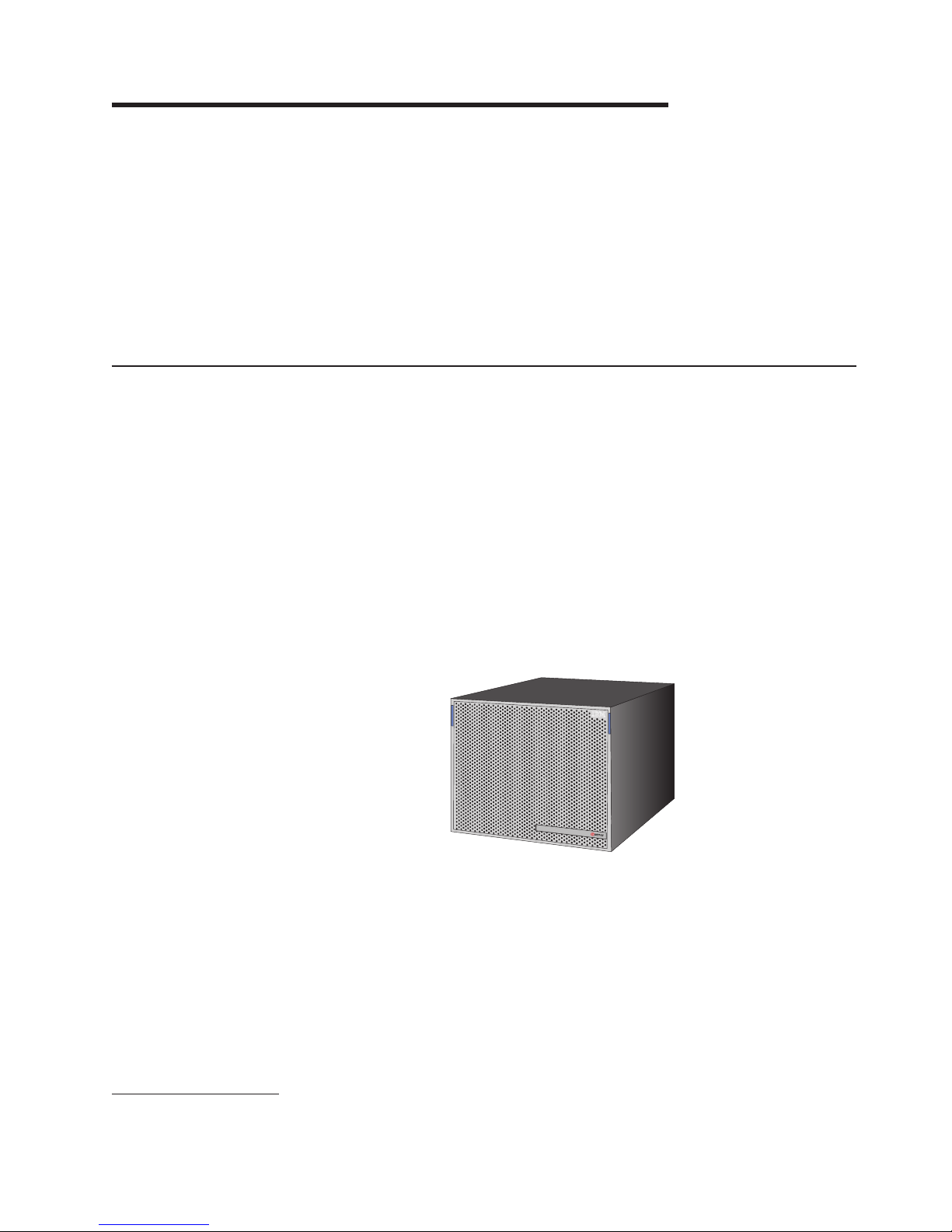
Figure 1 represents the BladeCenter T unit.
Figure 1. BladeCenter T unit
The BladeCenter T supports up to eight blade servers, making it ideally suited for
networking environments that require a large number of high-performance servers
in a small amount of space. The BladeCenter T system provides common resources
that are shared by the blade servers, such as power, cooling, system management,
network connections, and I/O (CD-ROM drive, ports for universal serial bus (USB),
keyboard, video, mouse, and network interfaces). The use of common resources
enables small size in the blade servers, allows minimal cabling, and eliminates
resources sitting idle.
1. IBM Enterprise X-Architecture Technology takes full advantage of existing IBM technologies to build powerful, scalable, and reliable
Intel® processor-based servers. For more information about IBM Enterprise X-Architecture Technology, go to www.ibm.com/servers/
eserver/xseries/xarchitecture/enterprise/.
© Copyright IBM Corp. 2004, 2006 1
Page 16

Performance, ease of use, reliability (NEBS3/ETSI compliance), and expansion
capabilities were key considerations during the design of the BladeCenter T system.
These design features make it possible for you to customize the system hardware
to meet your needs today, while providing flexible expansion capabilities for the
future.
What the BladeCenter T unit offers
The design of the BladeCenter T unit takes advantage of advances in server
technology. It provides up to eight functionally separate servers and their shared
resources combined in a single center. The BladeCenter T unit with blade servers
has the following features:
v IBM Enterprise X-Architecture Technology
IBM Enterprise X-Architecture Technology leverages proven innovative IBM
technologies to build powerful, scalable, reliable Intel®-processor-based servers.
IBM Enterprise Technology includes features such as IBM Predictive Failure
Analysis® (PFA), scalability, and real-time diagnostics.
v Expansion capabilities
Blades can be added to the BladeCenter T unit as needed, up to a maximum of
eight blades.
If any blade server or option is in blade bays 5 through 8 or if an I/O
Note:
module is in I/O-module bays 3 and 4, power modules must be present in
all four power-module bays.
Some blade servers have connectors for options that can be used to add
capabilities to the blade server, such as an I/O expansion card to add a network
interface or a storage expansion unit to add SCSI hard disk drives.
v Hot-swap capabilities
The front bays on the BladeCenter T unit are hot-swap blade, power module, and
management module bays; the rear bays on the BladeCenter T unit are hot-swap
I/O, keyboard, video, and mouse (KVM), LAN, and blower-module bays. Yo u can
add, remove, or replace blades servers or power, management, I/O, KVM, LAN,
and blower modules in hot-swap bays within specific time limits and without
removing power from the BladeCenter T unit.
Attention: To maintain proper system cooling, each unoccupied bay must
contain a filler blade or filler module.
v Redundancy capabilities
The redundant components in the BladeCenter T unit enable continued operation
if one of the components fails.
– Power modules: In normal operation, the redundant power modules provide
redundant power feeds to share the system load. If one of the power modules
fails, the working power module handles the entire load. Yo u can then replace
the failed power module without shutting down the BladeCenter T unit.
– Blowers: In normal operation, the redundant blower modules share the system
load. If one of the blowers fails, the other three working blowers handle the
entire load. Yo u can then replace the failed blower without shutting down the
BladeCenter T unit.
– Management module: Only one management module is active at a time. If a
second management module has been installed, and the active management
module fails, then the secondary (redundant) management module becomes
the active management module containing the current BladeCenter T
configuration and status information. Yo u can then replace the failed
management module without shutting down the BladeCenter T unit.
2 BladeCenter T Types 8720 and 8730: Planning and Installation Guide
Page 17

– BladeCenter T backplane characteristics: The backplane has the following
redundancy characteristics:
- Hot-pluggable connectors for the following components:
v Eight blades servers
v Four I/O modules
v Two management modules
v Four power supplies
v Four blowers
- Redundant high-speed serialize/deserialize (SERDES) interconnects
between blades and switches
- Support for redundant management modules
- Redundant 12C communications between the management modules and all
modules (except the blade servers)
- Redundant RS-485 (EIA 485) communications between management
modules and blade servers
- Redundant analog video connections from blades to management modules
- Redundant USB connections between blades and management modules
- Redundant secure Ethernet management port between switches and
management modules
Chapter 1. Introducing the BladeCenter T units 3
Page 18

v Redundant network connection capabilities
Configuring a pair of Ethernet switch modules in I/O-module bays 1 and 2
provides support for Ethernet failover configured on blade servers. If the I/O
expansion options can be configured for failover, configuring a pair of switch
modules in I/O-module bays 3 and 4 provides support for the failover configured
on the I/O expansion options. See the documentation that comes with your I/O
expansion and switch module options for more information about configuring for
redundant network connections.
A system configuration with I/O expansion options in I/O-module bays 3
Note:
and 4 requires a unit configuration with power supplies in power-module
bays 3 and 4.
Other network-interface I/O expansion options, such as the IBM BladeCenter T
Fibre Channel Expansion Card, can have similar capability for redundant network
connections. See the documentation that comes with your I/O expansion module
and I/O module options for more information about configuring for redundant
network connections.
v System-management capabilities
The BladeCenter T unit comes with a service processor in the management
module. This service processor in the management module, the
system-management firmware that is provided with the BladeCenter T unit, and
the service processor in each blade server, enable you to remotely manage the
BladeCenter T unit, its components, and the blade servers. The management
module also multiplexes the keyboard, mouse, video ports, and the USB port
across all blade servers.
The service processor in each blade server provides blade server system
monitoring, event recording, and alert capability.
v Network environment support
The BladeCenter T unit supports up to two Ethernet-compatible I/O modules
(switch modules or pass-through modules), for blade server integrated Ethernet
controller communication with the network. Each I/O module provides one
internal connection to each blade server, with up to eight internal connections per
I/O module. In addition, each Ethernet-compatible I/O module provides four
external connections to the user’s network infrastructure. These connections
support LAGs, VLANs, and other network protocols dependent on the model
installed.
The BladeCenter T unit also supports up to two additional I/O modules for a total
of four I/O modules. The two additional I/O modules support the network
interface on the optional I/O expansion card installed on one or more blade
servers in the BladeCenter T unit.
The two additional I/O modules must be compatible with the network
Note:
interface on the optional I/O expansion cards in the blade servers.
Each of these two additional I/O modules provides one internal connection to the
optional I/O expansion card, with up to eight internal connections per I/O module.
Reliability, availability, and serviceability
Three of the most important features in server design are reliability, availability, and
serviceability (RAS). These factors help to ensure the integrity of the data stored on
the blade server; that the blade server is available when you want to use it; and
that should a failure occur, you can easily diagnose and repair the failure with
minimal inconvenience.
4 BladeCenter T Types 8720 and 8730: Planning and Installation Guide
Page 19

The BladeCenter T unit has the following RAS features:
v Shared key components, such as power, cooling, backplane, and I/O
v All components serviced from the front or rear of the BladeCenter T unit
v Automatic error retry and recovery
v Automatic restart after a power failure
v Built-in monitoring for blower, power, temperature, and voltage
v Built-in monitoring for module redundancy
v Customer support center 24 hours a day, 7 days a week
2
v Error codes and messages
v Fault-resistant startup
v Remote system management through the management module
v Remote management module firmware upgrade
v Remote upgrade of blade server service processor microcode
v Built-in self-test (BIST)
v Predictive Failure Analysis (PFA) alerts
v Redundant components
– Blowers with speed-sensing capability
– Power modules
– Management modules
– I/O modules
Redundant system features in the backplane
v
v Hot-swap components
– Blade servers
– Blowers with speed-sensing capability
– I/O modules
– KVM module
– LAN module
– Management module
– Media tray
– Power modules
System automatic inventory at startup
v
v System error logging
2. Service availability will vary by country. Response time varies; may exclude holidays.
Chapter 1. Introducing the BladeCenter T units 5
Page 20

Features and specifications for the BladeCenter T Type 8720
Table 1 provides a summary of the features and specifications for the
BladeCenter T Type 8720 that is a dc-powered system.
Table 1. BladeCenter T Type 8720 features and specifications
Media tray (on front):
v DVD/CD-RW drive: slim IDE
v Two USB V2.0 Full Speed ports
v System-status panel
Module bays (on front):
v Eight hot-swap blade bays
v Four hot-swap power-module bays
v Two hot-swap management-module
bays
bays (on rear):
Module
v Four hot-swap I/O module bays
v Four hot-swap blower bays
v One hot-swap KVM module
v One hot-swap LAN module
modules:
Power
v Standard: Two 1300-watt or greater
hot-swap -48 V dc (-48 to -60 V dc)
power modules
– Power modules 1 and 2 supply
power to:
- Blade bays 1 through 4
- Management modules 1 and 2
- I/O modules 1 and 2
- Media tray
- All KVM, LAN, and alarm
interfaces
- All four blower modules
Power modules 1 and 2 provide
–
redundancy to each other
v Maximum: Four 1300-watt or greater
hot-swap -48 V dc (-48 to -60 V dc)
power modules
– Power modules 3 and 4 supply
power to:
- Blade bays 5 through 8
- I/O modules 3 and 4
Power modules 3 and 4 provide
–
redundancy to each other
– Blowers are powered by all four
power modules
module:
LAN
v Two 10/100-Mbps Ethernet remote
management connections
v One DSUB 15P alarm connector
module:
KVM
v Video port (analog)
v IBM PS/2® keyboard port
v PS/2 mouse port
v System-status panel
I/O modules:
v Standard: None
v Maximum: Four
– Two hot-swap 1-GB Ethernet
four-port switch modules
– Two hot-swap switch modules of
another network-communication
standard, such as Fibre Channel
Management
module:
v Standard: One hot-swap management
module providing system-management
functions for the BladeCenter T unit
v Maximum: Two hot-swap management
modules (one active, one redundant)
Redundant cooling:
Four variable-speed hot-swap blowers
bezel with changeable filter
Front
Upgradeable microcode:
v Management-module firmware
v I/O module firmware (not all I/O module
types)
v Blade server service processor firmware
(BIOS, service processor)
(8U):
Size
v Height: 349.25 mm (13.75 in. or 8 U)
v Depth: 508 mm (20 in.) from front of
chassis to rear I/O connector plane
Maximum depth:
600 mm (23.62 in.) including bezel,
handles, and cable bend radius
v Width: 442 mm (17.4 in.)
v Weight:
– Fully configured with modules and
blades: approximately 86.64 kg (191
lb)
– Fully configured without blades:
approximately 44.45 kg (98 lb)
Security
features:
v Login password for remote connection
v Secure shell (SSH) for command line
interface
v Secure Sockets Layer (SSL) security for
remote Web management access
Predictive
Failure Analysis (PFA) alerts:
v Blowers
v Blade-dependent features
v Power supplies
Declared acoustical noise emission levels
for normal operations:
v Sound-power levels (upper-limit): 7.5 bels
v Sound-pressure levels (average) for four
one-meter bystander positions: 59 dBA
noise emission levels stated are the
The
declared upper limit sound-power levels, in
bels, for a random sample of machines. All
measurements made in accordance with ISO
7779 and reported in conformance with ISO
9296.
Environment:
v Air temperature:
– Altitude: -60 to 1800 m (-197 ft to 6000
ft)
- BladeCenter T on: 5° to 40° C (41° to
104° F)
- BladeCenter T on (short term): -5° to
55° C (23° to 131° F)
Altitude: 1800 m to 4000 (6000 ft to
–
13000 ft)
- BladeCenter T on: 5° to 30° C (41° to
86° F)
- BladeCenter T on (short term): -5° to
45° C (23° to 113° F)
– System unit off: uncontrolled
Rate of temperature change: 30° C/hour
v
(54° F/hour)
v Humidity:
– BladeCenter T unit on: 5% to 85%
– BladeCenter T on (short term): 5% to
90% not to exceed 0.024 water/kg of dry
air
– BladeCenter T unit off: uncontrolled
Electrical
input:
v dc power
v Input voltage: -38 V dc to -75 V dc (-48 V
nominal)
v Input current:
– Chassis: 70 amp maximum
– Single power-supply feed: 70 amp
maximum
output:
Heat
v Input kilovolt-amperes (kVA) approximately
– Minimum configuration: 0.2 kVA
– Maximum configuration: 3.3 kVA
v BTU output
– Ship configuration:
673 BTU/hour (197 watts)
– Full configuration:
11229 BTU/hour (3291 watts)
6 BladeCenter T Types 8720 and 8730: Planning and Installation Guide
Page 21

Features and specifications for the BladeCenter T Type 8730
Table 2 provides a summary of the features and specifications for the
BladeCenter T Type 8730 that is an ac-powered system.
Table 2. BladeCenter T Type 8730 features and specifications
Media tray (on front):
v DVD/CD-RW drive: slim IDE
v Two USB V2.0 Full Speed ports
v System-status panel
Module bays (on front):
v Eight hot-swap blade bays
v Four hot-swap power-module bays
v Two hot-swap management-module
bays
bays (on rear):
Module
v Four hot-swap I/O module bays
v Four hot-swap blower bays
v One hot-swap KVM module
v One hot-swap LAN module
modules:
Power
v Standard: Two 1300-watt or greater
220-volt (200-240 V ac) hot-swap
power modules
– Power modules 1 and 2 supply
power to:
- Blade bays through 1 and 4
- Management modules 1 and 2
- I/O modules 1 and 2
- Media tray
- All KVM, LAN, and alarm
interfaces
- All four blower modules
Power modules 1 and 2 provide
–
redundancy to each other
v Maximum: Four 1300-watt or greater
220-volt (200-240 V ac) hot-swap
power modules
– Power modules 3 and 4 supply
power to
- Blade bays 5 through 8
- I/O modules 3 and 4
Power modules 3 and 4 provide
–
redundancy to each other
– Blowers are powered by all four
power modules
module:
LAN
v Two 10/100-Mbps Ethernet remote
management connections
v One DSUB 15P alarm connector
module:
KVM
v Video port (analog)
v PS/2 keyboard port
v PS/2 mouse port
v System-status panel
I/O modules:
v Standard: None
v Maximum: Four
– Two hot-swap 1-GB Ethernet
four-port switch modules
– Two hot-swap switch modules of
another network-communication
standard, such as Fibre Channel
Management
module:
v Standard: One hot-swap management
module providing system-management
functions for the BladeCenter T unit
v Maximum: Two hot-swap management
modules: one active, one redundant
Redundant cooling:
Four variable-speed hot-swap blowers
bezel with changeable filter
Front
Upgradeable microcode:
v Management-module firmware
v I/O module firmware (not all I/O module
types)
v Blade server service processor firmware
(BIOS, service processor)
(8U):
Size
v Height: 349.25 mm (13.75 in. or 8 U)
v Depth: 508 mm (20 in.) from front of
chassis to rear I/O connector plane.
Maximum depth: 600 mm (23.62 in.)
including bezel, handles, and cable
bend radius.
v Width: 442 mm (17.4 in.)
v Weight:
– Fully configured with modules and
blades: approximately 86.64 kg (191
lb)
– Fully configured without blades:
approximately 44.45 kg (98 lb)
Security
features:
v Login password for remote connection
v Secure shell (SSH) for command line
interface
v Secure socket layer (SSL) security for
remote Web management access
Predictive
Failure Analysis (PFA) alerts:
v Blowers
v Blade-dependent features
v Power supplies
Declared acoustical noise emission levels
for normal operations:
v Sound-power levels (upper-limit): 6.7 bels
v Sound-pressure levels (average) for four
one-meter bystander positions: 57 dBA
noise emission levels stated are the
The
declared upper limit sound-power level, in
bels, for a random sample of machines. All
measurements made in accordance with ISO
7779 and reported in conformance with ISO
9296.
Environment:
v Air temperature:
– Altitude: -60 to 1800 m (-197 ft to 6000
ft)
- BladeCenter T on: 5° to 40° C (41° to
104° F)
- BladeCenter T on (short term): -5° to
55° C (23° to 131° F)
Altitude: 1800 m to 4000 (6000 ft to
–
13000 ft)
- BladeCenter T on: 5° to 30° C (41° to
86° F)
- BladeCenter T on (short term): -5° to
45° C (23° to 113° F)
– System unit off: uncontrolled
Rate of temperature change: 30° C/hour
v
(54° F/hour)
v Humidity:
– BladeCenter T unit on: 5% to 85%
– BladeCenter T on (short term): 5% to
90% not to exceed 0.024 water/kg of dry
air
– BladeCenter T unit off: uncontrolled
Electrical
input:
v Sine-wave input (50 or 60 Hz single-phase)
required
v Input voltage:
– Minimum: 200 V ac
– Maximum: 240 V ac
Input current:
v
– Chassis: 18 amp maximum
– Single power-supply feed: 9 amp
output:
Heat
v Input kilovolt-amperes (kVA) approximately
– Minimum configuration: 0.2 kVA
– Maximum configuration: 3.1 kVA
BTU output
v
– Ship configuration: 673 BTU/hour (197
watts)
– Full configuration: 10440 BTU/hour
(3060 watts)
Chapter 1. Introducing the BladeCenter T units 7
Page 22

Why blade servers?
As organizations look to physically consolidate servers, they are looking to replace
bulky server towers with 1U or 2U rack systems. These systems take less space
and put the enterprise server infrastructure within easy reach of the administrator.
However, these rack systems also introduce certain issues.
Each 1U or 2U server requires its own infrastructure, including power cables,
Ethernet or fibre-channel switches, systems management, power distribution units
(PDUs), and keyboard/video/mouse (KVM) switches. A rack of 42 1U servers can
have hundreds of cables strung throughout the rack, making it difficult to determine
where cables are attached and increasing the complexity of adding or removing
servers from the rack.
A blade server is a rack-optimized server architecture designed to provide the
consolidation benefits of 1U and 2U rack systems while eliminating the
complications associated with these systems. A server blade is an independent
server containing one or more processors, memory, disk storage, and network
controllers. A server blade runs its own operating system and applications.
Each server blade is inserted into a slot at the front of the BladeCenter T unit and
connects to the midplane. The midplane provides a connection to shared
infrastructure components that include power, blowers, CD-ROM, integrated
Ethernet and fibre-channel switches, and the management module.
Blade server benefits
BladeCenter T is a robust, highly available architecture designed to integrate the
latest server processors, storage, and networking technology together into the
domain of the telecommunications central office and other rugged environments.
Benefits of the blade server architecture include:
v Modular scalability. Unlike traditional 8- or 16-way servers, blade servers are
designed to scale out rather than up. Adding a new server typically involves
simply sliding a new single- or dual-processor blade into an open bay in a
BladeCenter T unit. There is no need to physically install and cable individual
servers.
Option modules allow shared infrastructure features, such as Gigabit Ethernet
switches and fibre-channel switches, to be included inside the BladeCenter T unit
rather than externally attached. Power modules are also integrated into the unit,
thus eliminating many of the power cables and power distribution units that
conventional servers require. This design along with its support for network
attached storage (NAS) and storage area networks (SANs) allows the
BladeCenter T to integrate into a scalable storage solution with enhanced
manageability features.
v Flexibility. Unlike conventional server designs, the blade design does not impose
a limit of only one type of processor per server. Advanced chassis designs with
sophisticated cooling and power technologies can support a mix of blades
containing different types and speeds of processors. Each blade is a
self-contained server, running its own operating system and software. This
flexibility eliminates the need for stand alone servers to perform specific
functions. Yo u can consolidate your workloads in one BladeCenter T unit,
regardless of whether an application requires a high-performance 64-bit
processor or a 32-bit processor.
v Performance. Yo u can get the same high-performance processor technologies in
the BladeCenter T processor platform as in 1U rack-optimized servers. High
8 BladeCenter T Types 8720 and 8730: Planning and Installation Guide
Page 23

performance and scalability are powered by Intel DP Xeon™ 2W/800 MHz FSB
and Intel MP Xeon 4W/400 MHz FSB processors with 533 MHz front-side bus
speed. Other high-performance features include high-speed 512 MB Double Data
Rate ECC SDRAM memory, featuring optional Chipkill™ memory for reliability,
duel Gigabit Ethernet controllers with teaming and failover support, integrated
service processor, and connections for SCSI hard disk drives.
v Density. Yo u get double the density versus IBM carrier-grade rack-mount servers
at a potentially lower cost. Up to 80 processors can be integrated into an 84-inch
Telco rack. Blades can be used for control plane applications such as
VoIP/softswitch, transport plane applications such as signalling, wireless and
media gateways, service plane applications such as provisioning and network
management, and application plane applications such as unified communications,
IP centrex, and billing.
v High availability and ease of serviceability. Blade server designs include
high-availability features similar to those found in conventional rack servers, such
as redundant and hot-swap components (even the hot swapping of the blade
servers themselves). Removing a server for maintenance involves simply sliding
a blade out of the BladeCenter T unit, which makes a policy of hot-spare servers
effective to implement. In addition, you can configure blades to fail over to one
another in the event of a failure.
v Systems management and deployment. In blade servers, integrated systems
management processors monitor the status of blades and modules all at once. In
the event of an alert, the processors can signal the systems management
software, which can then notify the administrator by e-mail or pager at any hour
of the day or night. In addition, the software is able to run system diagnostics
and integrate with enterprise-wide systems management software.
The ability to slide server blades in and out of the BladeCenter T unit makes new
server deployment more efficient. When you insert a blade into an open bay, it is
connected to all infrastructure components in the BladeCenter T unit. There is
typically no need to plug multiple cables into each server as it is installed. For
example, instead of having to attach a KVM cable, power cable, Ethernet cable,
and systems management cable per server, you need to attach only one of each
cable per BladeCenter T unit, which contains multiple servers.
Deployment scenarios
The IBM BladeCenter T unit can be deployed to support a variety of networking
goals and environments, such as:
v Central Office (CO) environment
IBM BladeCenter T is ideally suited for telecom or carrier-grade environments
that require maximum equipment operability.
v Server consolidation
The IBM BladeCenter T unit can be used by organizations with multiple server
locations that need to centralize or physically consolidate servers to increase
flexibility, reduce maintenance costs, and reduce human resources.
v e-business infrastructure
The IBM BladeCenter T unit can be used by companies that need to deploy new
e-commerce and e-business applications and infrastructure quickly to minimize
time to market, while at the same time ensuring flexibility, scalability, and
availability.
v Enterprise infrastructure
The IBM BladeCenter T unit can support an enterprise infrastructure through:
Chapter 1. Introducing the BladeCenter T units 9
Page 24

File and print: For organizations with decentralized or departmental file and
print servers that need to reduce the cost of ownership, increase reliability,
and provide flexibility for growth.
Collaboration: For customers needing a cost-effective and reliable corporate
solution for e-mail, calendar, and other collaboration capabilities.
High-performance computing
v
The IBM BladeCenter T unit can be used by customers with compute-intensive
applications needing highly available clustered solutions to achieve significantly
higher degrees of scalability and performance, all managed at a low cost.
Where to go for more information
The following publications and Web sites provide additional information about the
installation, configuration, and operation of your IBM BladeCenter T unit.
BladeCenter T documentation and operating system installation
instructions
Publications available for the BladeCenter T products are listed in the following
sections. Unless noted otherwise, all documents are available for download from
the IBM Support Web page at www.ibm.com/pc/support/. From this Web page,
select Servers, then select Online publications and choose a machine type of
BladeCenter T or BladeCenter T HS20 from the Family drop-down list.
You can obtain up-to-date information about the BladeCenter T unit, blade server,
and other IBM server products at www.ibm.com/eserver/xseries/
Hardware documentation
Publications available for BladeCenter T products include:
v IBM BladeCenter T Products FAQ Hints and Tips
This document contains information based on technical observations and is
intended to supplement the IBM BladeCenter T publications provided with the
BladeCenter T products.
v IBM BladeCenter T Types 8720 and 8730 Installation and User’s Guide
This document contains general information about the BladeCenter T Types 8720
and 8730, including information about features, how to configure the BladeCenter
T unit, and how to get help.
v IBM BladeCenter T Types 8720 and 8730 Hardware Maintenance Manual and
Troubleshooting Guide
This document contains the information to help you solve BladeCenter T
problems and information for service technicians.
v IBM BladeCenter HS20 Type 8832 Installation and User’s Guide
This document contains instructions for setting up a BladeCenter HS20 Type
8832 blade server and basic instructions for installing options. It also contains
general information about the blade server.
v IBM BladeCenter HS20 Type 8832 Hardware Maintenance Manual and
Troubleshooting Guide
This document contains the information to help you solve BladeCenter HS20
Type 8832 problems and information for service technicians.
v IBM BladeCenter HS40 Type 8839 Installation and User’s Guide
This document contains instructions for setting up a BladeCenter HS40 Type
8839 blade server and basic instructions for installing options. It also contains
general information about the blade server.
10 BladeCenter T Types 8720 and 8730: Planning and Installation Guide
Page 25

v IBM BladeCenter HS40 Type 8839 Hardware Maintenance Manual and
Troubleshooting Guide
This document contains the information to help you solve BladeCenter HS40
Type 8839 problems and information for service technicians.
v IBM BladeCenter T 2-Post Rack Installation Instructions
This document contains instructions for installing BladeCenter T units in a 2-post
rack.
v IBM BladeCenter T 4-Post Rack Installation Instructions
This document contains instructions for installing BladeCenter T units in a 4-post
rack.
v IBM BladeCenter T Advanced Management Module User ’s Guide
This document contains detailed information about the Management Module that
comes with the BladeCenter T unit.
v IBM BladeCenter T Advanced Management Module Installation Guide
This document contains instructions for installing the Management Module that
comes with the BladeCenter T unit.
v IBM BladeCenter T 4-Port Fibre Channel Switch Module User’s Guide
This document contains information about setting up and installing the 4-port
Fibre Channel switch module.
v IBM BladeCenter SCSI Storage Expansion Unit
This document contains instructions for installing the optional SCSI storage
expansion unit on a blade server.
v IBM Microprocessor Option
This document contains instructions for installing the optional microprocessor in a
blade server.
v IBM BladeCenter T Type 8720 DC Power Supply Modules
This document contains instructions for installing the optional dc power supply
modules in a BladeCenter T unit.
v IBM BladeCenter T Type 8730 AC Power Supply Modules
This document contains instructions for installing the optional ac power supply
modules in a BladeCenter T unit.
v IBM Director 4.2 Installation and Configuration Guide and IBM Director 4.2
Systems Management Guide.
These documents are available for download from the IBM Support Web page at
http://www.ibm.com/pc/support/. From this Web page, select Servers, then select
Online publications and choose IBM Director from the Online publications by
category drop-down list. These guides contain instructions for using IBM Director
4.2 to perform installation, configuration, and systems management tasks on the
BladeCenter T products.
Redbooks publications
The following publications are available from the IBM Redbooks™ Web site at
www.ibm.com/redbooks. From this Web site, search for BladeCenter.
v The Cutting Edge: IBM BladeCenter (REDP3581): This document contains an
introduction to the IBM BladeCenter unit and presents the advantages of blade
servers. It also looks at various installation methods that are available and
important items to consider before performing an installation.
v IBM BladeCenter Systems Management (REDP3582) : This document contains
an overview of the IBM BladeCenter management tools and describes the
management module integrated Web graphical user interface (GUI).
Chapter 1. Introducing the BladeCenter T units 11
Page 26

v Deploying Citrix Metaframe on IBM BladeCenter (REDP3583): This document
describes the installation, functionality, and advantages of Citrix Metaframe on
the HS20 blade server.
v Deploying Lotus® Domino® on IBM BladeCenter (REDP3584): This document
helps you set up and configure IBM BladeCenter products to run IBM Lotus
Domino 6 on Microsoft® Windows® 2000 Advanced Server. It also helps you tune
Lotus Domino 6 for better performance while running in an IBM BladeCenter T
environment.
v Deploying Microsoft Exchange on IBM BladeCenter (REDP3585): This document
describes how to set up and configure Microsoft Exchange 2000 on the IBM
BladeCenter unit. It also describes BladeCenter functionality in this type of
environment.
v Deploying Apache on IBM BladeCenter (REDP3588): This document helps you
set up and configure IBM BladeCenter products to run Linux® and Apache. It also
provides tips on the applications to use for managing the installation.
v Deploying Samba on IBM BladeCenter (REDP3595): This document helps you
set up and configure IBM BladeCenter products to run Linux and Samba. It also
provides tips for managing the installation.
Operating system installation instructions
Instructions for installing operating systems on a blade server are on the IBM
Support Web page at www.ibm.com/pc/support/. From the IBM Support Web page
select Servers; then, select OS installation and choose the operating system to
install from the Operating system installation by category drop-down list.
Web sites
You can find information about the BladeCenter T unit from this Web site:
www.ibm.com/systems/bladecenter/literature/solutions_lit.html
These sites provide information related to installation of the BladeCenter T unit:
v Information about IBM Director is available at this Web site:
www.ibm.com/servers/eserver/xseries/systems_management/ibm_director/
v Information about Remote Deployment Manager (RDM) is available at this Web
site:
www.ibm.com/servers/eserver/xseries/systems_management/ibm_director/extensions/
rdm.html
v Information about IBM Cluster Systems Management (CSM) for Linux is available
at this Web site: www.ibm.com/servers/eserver/clusters/software/
v Information about installing Linux is available at this Web site:
www.ibm.com/servers/eserver/linux/xseries/
v You can link to configuration tools and information (such as the Rack
Configurator and the Configuration Options Guide) from this site:
www.ibm.com/pc/us/eserver/xseries/library/configtools
v You can find out about the training offered by IBM for the BladeCenter T unit at
this Web site: www.ibm.com/systems/bladecenter/bladet/index.html
12 BladeCenter T Types 8720 and 8730: Planning and Installation Guide
Page 27
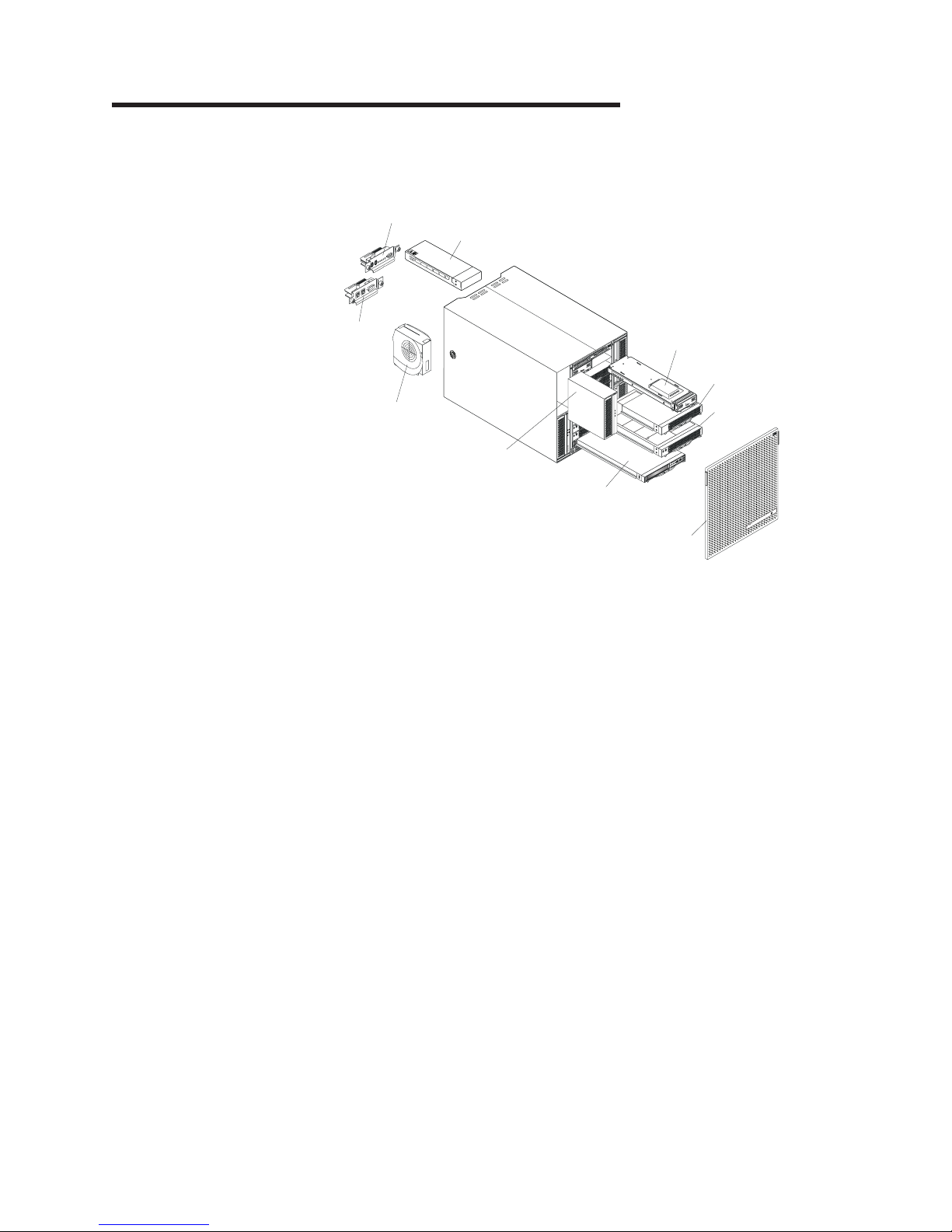
Chapter 2. BladeCenter T unit components
Figure 2 shows the locations of major components in the BladeCenter T unit.
KVM module
I/O module
LAN
module
A
C
1
3
0
0
W
O
D
C
U
T
A
I
C
N
Management module
Filler blade
Blower module
(4 units)
Power module
I
A
T
U
C
D
O
!
W
0
0
3
1
C
A
D
S
E
Blade server
!
O
D
C
U
T
A
I
C
N
N
C
Media tray
r
e
rv
e
s
Bezel assembly
Figure 2. Major BladeCenter T components
Attention: To maintain proper system cooling, each module bay must contain
either a module or a filler module, and each blade bay must contain either a blade
or a filler blade.
© Copyright IBM Corp. 2004, 2006 13
Page 28
Chassis
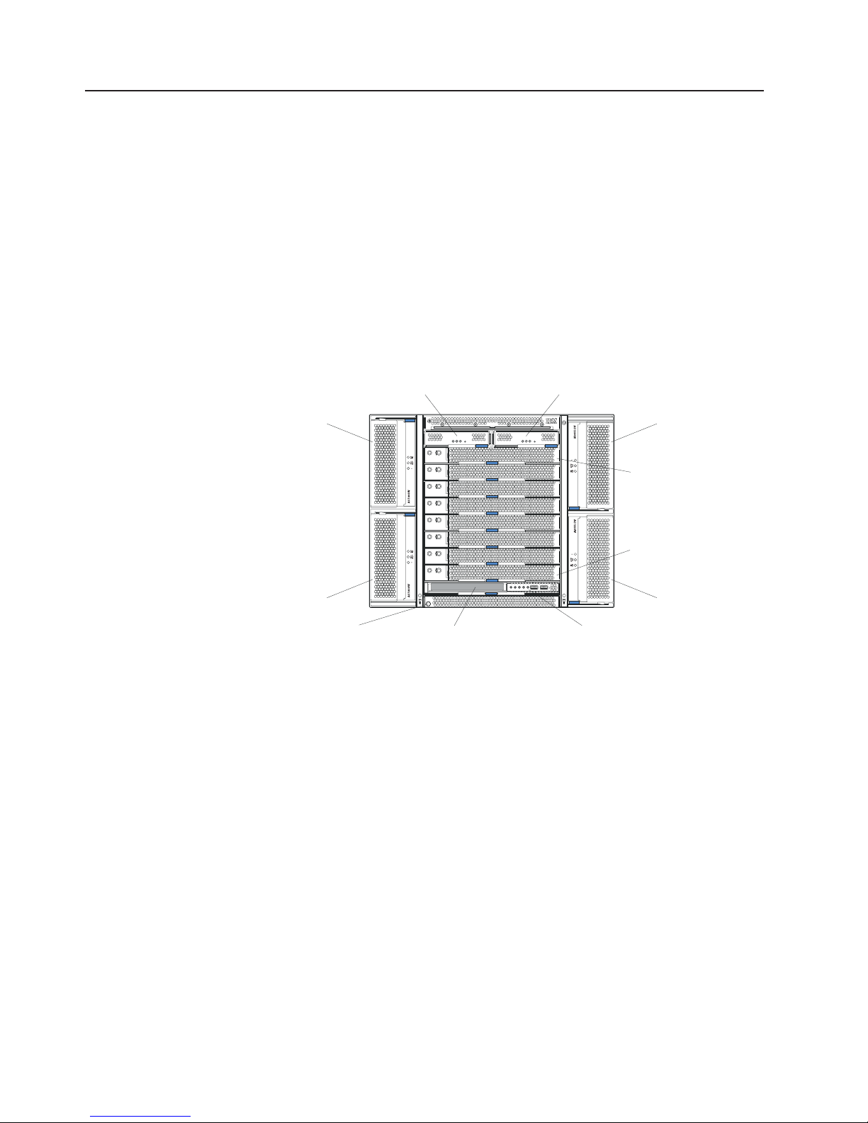
Front view
The BladeCenter T unit houses all components, including:
v Blade servers
v Management modules
v Power modules
v Blower modules
v I/O modules
v KVM modules
v LAN modules
v Media tray
Figure 3 identifies the components on the front of the BladeCenter T Types 8720
and 8730 units.
Management-module bay 1
Management-module bay 2
Power module 1
Power module 3
ESD connector
Figure 3. BladeCenter T front view
Power module 2
CMM
1
CMM
2
Blade server 1
Blade server 8
Power module 4
Front panelMedia tray
14 BladeCenter T Types 8720 and 8730: Planning and Installation Guide
Page 29
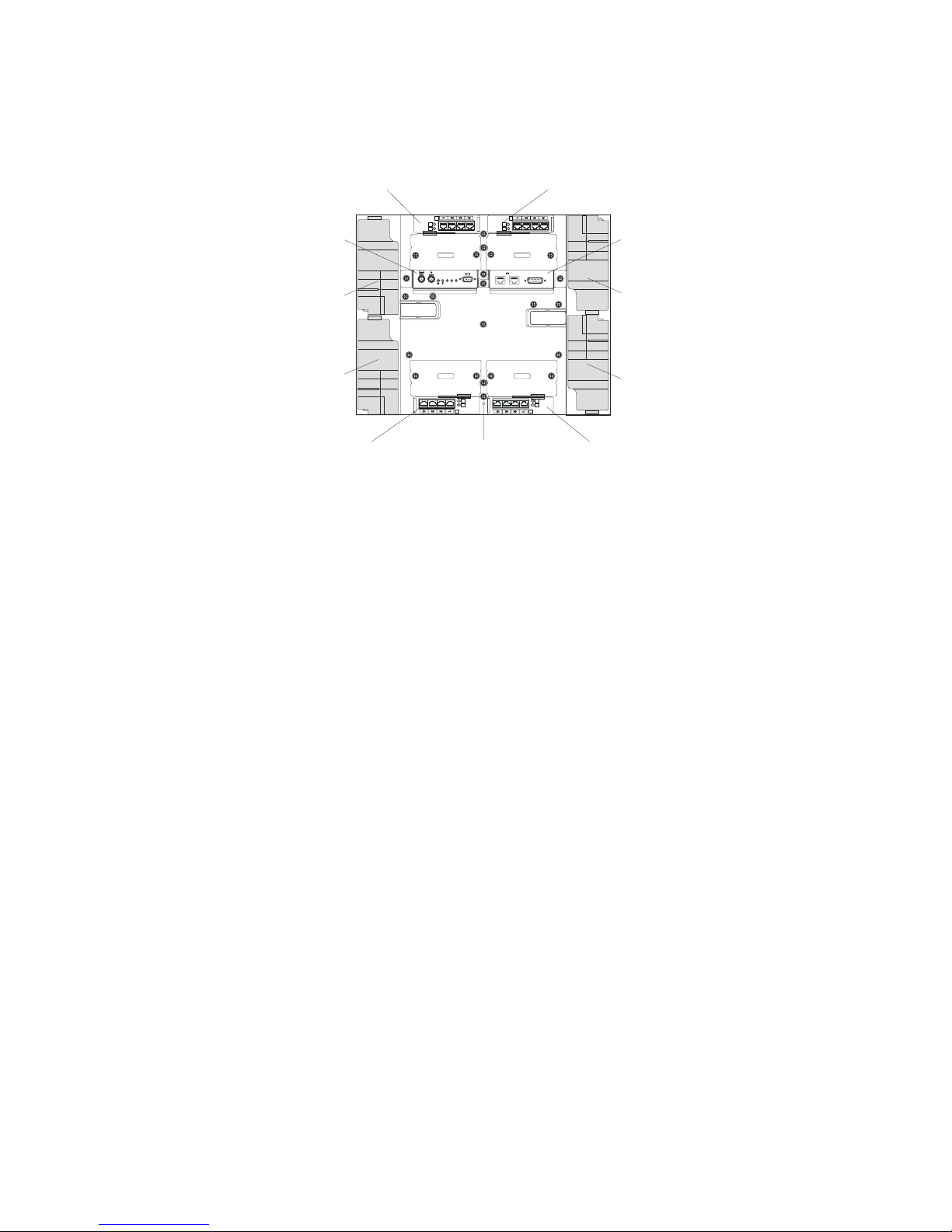
Rear view of the BladeCenter T unit
Figure 4 identifies the components on the rear of the BladeCenter T unit.
I/O module 2 I/O module 1
KVM module
TOP
D
CRT
MNR
MJR
Blower module 2
24
BTM
Blower module 4
I/O module 4
E
ESD connector
Figure 4. Components on the rear of the BladeCenter T unit
TOP
D
2
1
Alarms
Blower module 1
LAN module
13
BTM
E
Blower module 3
I/O module 3
Chapter 2. BladeCenter T unit components 15
Page 30

Input/output connectors
The BladeCenter T unit has the following ports:
Video
The BladeCenter T management module contains one standard video
connector. The integrated video controller on each blade server is
compatible with SVGA and VGA and communicates through this video port.
Use this connector to connect a video monitor.
Keyboard
Use this connector to connect an IBM PS/2 keyboard to the BladeCenter T
unit.
PS/2 mouse
Use this connector to connect a PS/2 mouse to the BladeCenter T unit.
Two USB connectors on the front of the BladeCenter T unit
The BladeCenter T unit has two USB connectors on the front panel of the
BladeCenter T unit.
These USB ports permit the direct connection of two USB peripherals
without an external hub. If more devices are required, an external hub can
be connected to any of the built-in ports. USB technology transfers data at
up to 12 Mb per second (Mbps) with a maximum of 127 devices and a
maximum signal distance of 5 m (16 ft) per segment. Using Plug and Play
technology, USB devices are configured automatically.
Two 10/100-Mbps Ethernet connectors for remote management and console
The BladeCenter T LAN module contains two 10/100-Mbps Ethernet ports
that provide the remote connection to the system management station on
the network, driven from each management module, to the network
management station on the network.
Use these ports for remote management and remote console.
The network management station, through these connectors, can access
control functions running in the management module, the service processor
on each blade server, or within each I/O module. However, it cannot use
these ports to communicate with application programs running in the blade
servers. The network management station must direct those
communications through a network connected to the external ports in the
I/O modules in the BladeCenter T unit.
Four 10/100/1000-Mbps Ethernet connectors on each Ethernet switch module
Each Ethernet switch module contains four Ethernet connectors.
Connect a Category 3, 4, 5, or higher unshielded twisted-pair (UTP) cable
to this connector. The 100BASE-TX and 1000BASE-T Fast Ethernet
standards require Category 5 or higher.
16 BladeCenter T Types 8720 and 8730: Planning and Installation Guide
Page 31

Figure 5 shows the I/O connectors on the rear of the BladeCenter T Type 8720.
I/O module 2 I/O module 1
Type 8720
KVM module
TOP
D
CRT
MJR
2
MNR
Blower module 2
BTM
Blower module 4
I/O module 4
E
ESD connector
Figure 5. BladeCenter T Type 8720 rear view - I/O connectors
Figure 6 shows the I/O connectors on the rear of the BladeCenter T Type 8730.
KVM module
Blower module 2
I/O module 2 I/O module 1
Type 8730
TOP
D
CRT
MJR
2
MNR
TOP
D
1
Alarms
BTM
E
TOP
D
1
Alarms
LAN module
Blower module 1
DC-power connectors
Blower module 3
I/O module 3
LAN module
Blower module 1
24
BTM
Blower module 4
I/O module 4
E
ESD connector
Figure 6. BladeCenter T Type 8730 rear view - I/O connectors
BTM
E
13
AC-power connectors
Blower module 3
I/O module 3
Chapter 2. BladeCenter T unit components 17
Page 32

2-way blade servers
The BladeCenter HS20 Type 8843 is high-performance 2-way blade server that is
ideally suited for networking environments that require superior microprocessor
performance, efficient memory management, flexibility, and reliable data storage
(see Figure 7).
The BladeCenter blade server will have one of the bezels shown in Figure 7.
Note:
The illustration might differ slightly from your hardware.
Release
levers
Figure 7. BladeCenter HS20 Type 8843
The IBM BladeCenter HS20 Type 8843 blade server is based on the IBM Enterprise
X-Architecture Technology.
3
3. IBM Enterprise X-Architecture Technology takes full advantage of existing IBM technologies to build powerful, scalable, and reliable
Intel processor-based servers. For more information about IBM Enterprise X-Architecture Technology, go to www.ibm.com/servers/
eserver/xseries/xarchitecture/enterprise/.
18 BladeCenter T Types 8720 and 8730: Planning and Installation Guide
Page 33

Features and specifications for the HS20 Type 8843 for a
non-NEBS/ETSI environment
Table 3 provides a summary of the features and specifications of the BladeCenter
HS20 Type 8843 blade server operating in a non-NEBS/ESI environment.
Power, cooling, removable media drives, external ports, and advanced
Note:
system management are provided by the BladeCenter T Types 8720 and
8730 units.
Table 3. 8843 Features and specifications
Microprocessor:
Supports up to 2 microprocessors
v Intel Xeon DP processor
v 1 MB ECC L2 cache
v 800 MHz front-side bus (FSB)
Memory:
v Four double data rate (DDR)
PC1600 sockets
v Minimum: 512 MB
v Maximum: 8 GB
v Type: 2-way interleaved, DDR,
PC3200, ECC SDRAM registered
x4 (Chipkill) dual inline memory
modules (DIMMs) only
Notes:
1. PC3200 DIMMs are
backward-compatible and can
function in the PC1600 sockets
2. Chipkill is available for DIMMs
with 512 MB or greater
Supports 512 MB, 1 GB, 2 GB, and
v
4 GB DIMMs
Drives:
v Support for up to two Ultra320
SCSI hot-swap hard disk drives
available in the optional SCSI
storage expansion unit
Size:
v Height: 24.5 cm (9.7 inches)
v Depth: 44.6 cm (17.6 inches)
v Width: 2.9 cm (1.14 inches)
v Maximum weight: 5.4 kg (12 lb)
Integrated functions:
v Two Gigabit Ethernet controllers
v ATI Rage XL video controller
v Light path diagnostics
v Local service processor
v IDE drive controller
v RS-485 interface for
communication with the
management module
v USB buses for communication
with keyboard, mouse, CD-ROM
drive, and external diskette drive.
Predictive
Failure Analysis (PFA)
alerts:
v Microprocessor
v Memory
v Hard disk drives
Electrical
input:
v Input voltage: 12 V dc
Environment:
v Air temperature:
– Blade server on: 10° to 35° C
(50° to 95° F). Altitude: 0 to 914
m (2998.69 ft)
– Blade server on: 10° to 32° C
(50° to 95° F). Altitude: 914 m to
2134 m (2998.69 ft to 7000 ft)
– Blade server off: -40° to 60° C
(-40° to 140° F)
v
Humidity:
– Blade server on: 8% to 80%
– Blade server off: 5% to 80%
Note: The operating system in the blade server must provide USB support for the
blade server to recognize and use the keyboard, mouse, CD-ROM, and
external diskette drive. The BladeCenter T unit uses USB for
communications with these devices.
Chapter 2. BladeCenter T unit components 19
Page 34

Features and specifications for the HS20 Type 8843 for a NEBS/ETSI
environments
Table 4 provides a summary of the features and specifications of the BladeCenter
HS20 Type 8843 blade server operating in a NEBS/ETSI environment.
Power, cooling, removable media drives, external ports, and advanced
Note:
system management are provided by the BladeCenter T Type 8720 unit.
Table 4. 8843 Features and specifications
Microprocessor:
Supports up to 2 microprocessors
v Intel Xeon DP processor
v 512 KB ECC L2 cache
v 533 MHz front-side bus (FSB)
Memory:
v Four double data rate (DDR)
PC3200 sockets
v Minimum: 1 GB
v Maximum: 8 GB
v Type: 2-way interleaved, DDR,
PC2100, ECC SDRAM registered
x4 (Chipkill) dual inline memory
modules (DIMMs) only
Notes:
1. PC2100 DIMMs are
backward-compatible and can
function in the PC1600 sockets
2. Chipkill is available for DIMMs
with 512 MB or greater
Supports 512 MB, 1 GB, and 2 GB
v
DIMMs
Drives:
v Support for up to two internal IDE
2.5-inch flash drives (NEBS
application requires flash-based
IDE drives)
v Support for up to two Ultra320
SCSI hot-swap hard disk drives
available in the optional SCSI
storage expansion unit
Size:
v Height: 24.5 cm (9.7 inches)
v Depth: 44.6 cm (17.6 inches)
v Width: 2.9 cm (1.14 inches)
v Maximum weight: 5.4 kg (12 lb)
Integrated functions:
v Two Gigabit Ethernet controllers
v ATI Rage XL video controller
v Light path diagnostics
v Local service processor
v IDE drive controller
v RS-485 interface for
communication with the
management module
v USB buses for communication
with keyboard, mouse, CD-ROM
drive, and external diskette drive.
Predictive
Failure Analysis (PFA)
alerts:
v Microprocessor
v Memory
Electrical
input:
v Input voltage: 12 V dc
Environment (NEBS):
v Air temperature:
– Blade server on: 5° to 40° C (41°
to 104° F). Altitude: -60 to 1800
m (-197 to 6000 ft )
– Blade server on (short term): -5°
to 55° C (23° to 131° F). Altitude:
-60 to 1800 m (-197 to 6000 ft)
– Blade server on: 5° to 30° C (41°
to 86° F). Altitude: 1800 to 4000
m (6000 to 13000 ft)
– Blade server on (short term): -5°
to 45°C (23° to 113° F). Altitude:
1800 to 4000 m (6000 to 13000
ft)
– Blade server off: -40° to 70° C
(-40° to 158° F)
v
Humidity:
– Blade server on: 5% to 80%
– Blade server on (short term): 5%
to 90%, but not to exceed 0.024
kg water/kg of dry air
– Blade server off: uncontrolled
Note: ″Short term″ refers to a
period of not more than 96
consecutive hours and a total of
not more than 15 days in 1 year.
(This refers to a total of 360
hours in any given year, but no
more than 15 occurrences during
that 1-year period.)
Note: The operating system in the blade server must provide USB support for the
blade server to recognize and use the keyboard, mouse, CD-ROM, and an
external diskette drive. The BladeCenter T unit uses USB for
communications with these devices.
20 BladeCenter T Types 8720 and 8730: Planning and Installation Guide
Page 35

4-way blade server
The BladeCenter HS40 Type 8839 is high-performance 4-way blade server that is
ideally suited for networking environments that require superior microprocessor
performance, efficient memory management, flexibility, and reliable data storage.
The BladeCenter blade server will have one of the bezels shown in Figure 8.
Note:
The illustration might differ slightly from your hardware.
Release
levers
Figure 8. BladeCenter HS40 Type 8839 blade server
The IBM BladeCenter HS40 Type 8839 blade server is based on the IBM Enterprise
X-Architecture Technology.
Release
button
4
4. IBM Enterprise X-Architecture Technology takes full advantage of existing IBM technologies to build powerful, scalable, and reliable
Intel processor-based servers. For more information about IBM Enterprise X-Architecture Technology, go to www.ibm.com/servers/
eserver/xseries/xarchitecture/enterprise/.
Chapter 2. BladeCenter T unit components 21
Page 36

BladeCenter HS40 Type 8839 features and specifications for
non-NEBSI/ETSI environment
Table 5 provides a summary of the features and specifications of the BladeCenter
HS40 Type 8839 blade server operating in a non-NEBS/ETSI environment.
Note: Power, cooling, removable media drives, external ports, and advanced
system management are provided by the BladeCenter T Types 8720 and
8730.
Table 5. HS40 features and specifications for a non-NEBSI/ETSI environment
Microprocessor:
Supports up to 4 microprocessors
v Intel Xeon 2.0 GHz or faster
v L2 and L3 caches, size dependent
on microprocessor
Memory:
v Eight double data rate (DDR)
PC2100 184-pin DIMM sockets
v Minimum: 512 MB
v Maximum: 16 GB¹
v Type: 2-way interleaved, DDR,
PC2100, ECC SDRAM registered
x4 (Chipkill) dual inline memory
modules (DIMMs) only
v Supports 256-MB, 512-MB, 1-GB,
and 2-GB DIMMs
v Hot spare memory
Expansion:
v Two I/0 expansion card connectors
Drives:
v Support for up to two Ultra320
SCSI hot-swap hard disk drives
available in an optional SCSI
storage expansion unit
Size:
v Height: 24.5 cm (9.7 inches)
v Depth: 44.6 cm (17.6 inches)
v Width: 5.9 cm (2.32 inches)
v Maximum weight: 7.0 kg (15.4 lb)
Integrated functions:
v Four Gigabit Ethernet controllers
v ATI Radeon 7000 video controller
v Light path diagnostics
v Local service processor
v IDE controller
v RS-485 interface for
communication with the
management module
v Integrated Baseboard
Management Controller
v USB V2.0 Full Speed ports for
communication with keyboard,
mouse, external diskette drive,
and CD-ROM drive²
v Serial over LAN (SOL)
management interface
Electrical
input:
v Input voltage: 12 V dc
Predictive Failure Analysis (PFA)
alerts:
v Microprocessor
v Memory
v Hard disk drives
Environment:
v Air temperature:
– Blade server on: 10° to 35° C
(50° to 95° F). Altitude: 0 to 914
m (2998.69 ft)
– Blade server on: 10° to 32° C
(50° to 95° F). Altitude: 914 m to
2134 m (2998.69 ft to 7000 ft)
– Blade server off: -40° to 60° C
(-40° to 140° F)
v
Humidity:
– Blade server on: 8% to 80%
– Blade server off: 5% to 80%
Notes:
1. You might have to enable large-memory support for your operating system to
access all of the memory that is installed in your blade server. See the
documentation for your operating system for information.
2. The operating system in the blade server must provide USB support for the
blade server to recognize and use the keyboard, mouse, external diskette drive,
and CD-ROM drive. The BladeCenter T unit uses USB for internal
communications with these devices.
22 BladeCenter T Types 8720 and 8730: Planning and Installation Guide
Page 37

BladeCenter HS40 Type 8839 features and specifications for a
NEBS/ETSI environment
Table 6 provides a summary of the features and specifications of the BladeCenter
HS40 Type 8839 blade server operating in a NEBS/ETSI environment.
Note: Power, cooling, removable media drives, external ports, and advanced
system management are provided by the BladeCenter T Types 8720 and
8730.
Table 6. HS40 features and specifications for a NEBS/ETSI environment
Microprocessor:
Supports up to 4 microprocessors
v Intel Xeon 2.0 GHz or faster
v L2 and L3 caches, size dependent
on microprocessor
Memory:
v Eight DDR PC2100 184-pin DIMM
sockets
v Minimum: 1 GB
v Maximum: 16 GB¹
v Type: 2-way interleaved, DDR,
PC2100, ECC SDRAM registered
x4 (Chipkill) dual inline memory
modules (DIMMs) only
v Supports 512-MB, 1-GB, and 2-GB
DIMMs
v Hot spare memory
Expansion:
v Two I/0 expansion card connectors
Drives:
v Support for up to two Ultra320
SCSI hot-swap hard disk drives
available in an optional SCSI
storage expansion unit
Size:
v Height: 24.5 cm (9.7 inches)
v Depth: 44.6 cm (17.6 inches)
v Width: 5.9 cm (2.32 inches)
v Maximum weight: 7.0 kg (15.4 lb)
Integrated functions:
v Four Gigabit Ethernet controllers
v ATI Radeon 7000 video controller
v Light path diagnostics
v Local service processor
v IDE controller
v RS-485 interface for
communication with the
management module
v Integrated Baseboard
Management Controller
v V2.0 Full Speed ports for
communication with keyboard,
mouse, external diskette drive,
and CD-ROM drive²
v Serial over LAN (SOL)
management interface
Electrical
input:
v Input power: 12 V dc
Predictive Failure Analysis (PFA)
alerts:
v Microprocessor
v Memory
v Hard disk drives
Environment:
v Air temperature:
– Blade server on: 5° to 40° C (41°
to 104° F). Altitude: -60 to 1800
m (-197 to 6000 ft)
– Blade server on (short term): -5°
to 55° C (23° to 131° F). Altitude:
-60 to 1800 m (-197 to 6000 ft)
– Blade server on (short term): 5°
to 30° C (41° to 86° F). Altitude:
1800 to 4000 m (6000 to 13000
ft)
Blade server on (short term): -5°
to 45° C (23° to 113° F). Altitude:
1800 to 4000 m (6000 to 13000
ft)
– Blade server off: -40° to 70° C
(-40° to 158° F)
v
Humidity:
– Blade server on: 5% to 80%
– Blade server on (short term): 5%
to 90% but not to exceed 0.024
kg water/kg of dry air
– Blade server off: uncontrolled
Short term refers to a period of
Note:
not more than 96 consecutive hours
and a total of not more than 15 days in
1 year. (This refers to a total of 360
hours in any given year, but no more
than 15 concurrences during that
1-year period.
Notes:
1. You might have to enable large-memory support for your operating system to
access all of the memory that is installed in your blade server. See the
documentation for your operating system for information.
2. The operating system in the blade server must provide USB support for the
blade server to recognize and use the keyboard, mouse, external diskette drive,
and CD-ROM drive. The BladeCenter T unit uses USB for internal
communications with these devices.
Chapter 2. BladeCenter T unit components 23
Page 38

Media tray
The media tray is a hot-swap unit that installs in the front of the BladeCenter T unit
and contains the system-status panel, two USB ports, and the CD-ROM drive (see
Figure 9).
Media tray
CD-ROM drive
Figure 9. BladeCenter T media tray
System-status panel
USB connectors
24 BladeCenter T Types 8720 and 8730: Planning and Installation Guide
Page 39

Management module
The BladeCenter T unit comes with one hot-swap Advanced Management Module
in management bay 1. An additional management module can be added in
management-module bay 2. Only one of these management modules can be active
at one time, functioning as the primary management module; a second
management module, if present, provides redundancy. The secondary management
module remains inactive until it is switched to act as primary.
When two management modules are installed in the BladeCenter T unit, both
management modules must have the same level of firmware, at a level that
supports redundant management-module function. This helps ensure a smooth
changeover of control from the active management module to the redundant
management module. The latest level of management-module firmware is available
at the IBM Support Web site at www.ibm.com/pc/support/.
The management module functions as a service processor and a KVM multiplexor
for all of the blade servers installed in the BladeCenter T unit. It controls the
KVM-module external connections for use by a local console. The management
module also controls three LAN-module external connections: two RJ-45 connectors
for 10/100-Mbps Ethernet remote management connection and an alarms connector
that can be used for monitoring BladeCenter T unit status.
The service processor in the management module communicates with the service
processor in each blade server to support features such as blade server power-on
requests, error and event reporting, KVM requests, and requests to use the
BladeCenter T shared-media tray (CD-ROM drive and USB port)
The BladeCenter T components are configured using the management module. The
management module communicates with all components in the BladeCenter T unit,
detecting their presence or absence, reporting their status, and sending alerts for
error conditions when they are required (see Figure 10 on page 26).
Chapter 2. BladeCenter T unit components 25
Page 40

Release button
Management module
Release latch
Figure 10. BladeCenter T advanced management module
Figure 11 shows the serial port connector on the management module. Table 7
shows the pinouts for the serial port connector.
15
Figure 11 . Serial port connector
Table 7. Pinouts for the serial port connector
Pin Number Description
1 DCD
2 RxD in
3 TxD out
4 DTR out
5 GND
6 DSR in
7 RTS out
8 CTS in
9 n/a
Note: n/a = Not applicable
69
Serial port
MAC address
You can use a serial cable to connect the management module to an external serial
port. Figure 12 on page 27 shows the serial cable. Table 8 on page 27 shows the
pin assignments for both ends of the serial cable. Connect the end labeled P1 to
26 BladeCenter T Types 8720 and 8730: Planning and Installation Guide
Page 41

the serial port on the management module, and connect the end labeled P2 to the
external serial port.
SKT 9
SKT 1
BLK
1
BRN
6
RED
2
ORG
3
YEL
4
P1 P2
SHELL
GRN
4
BLU
5
VIO
7
GRY
8
9
DRAIN WIRE
AND BRAID
4
4
3
2
1
6
5
8
7
9
SHELL
Figure 12. Optional serial cable for connecting the management module to an external serial port
P1
95
61
Table 8. Pin assignments for the optional serial cable
Description Serial Cable (P1) Serial Cable (P2)
DCD 1 4
RxD in 2 3
TxD out 3 2
DTR out 4 1,6
GND 5 5
DSR in 6 4
RTS out 7 8
CTS in 8 7
Chapter 2. BladeCenter T unit components 27
Page 42

Keyboard, video, and mouse module
The KVM module is a hot-swap unit that is installed in the rear of the BladeCenter
T unit. This module contains two PS/2 connectors for the keyboard and mouse, a
system-status panel, and an HD-15 video connector. (see Figure 13).
Thumbscrew
Keyboard
Mouse
Major (MJR) alarm LED
Minor (MNR) alarm LED
CRT
MNR
MJR
Figure 13. BladeCenter T KVM module
System-status LEDs: These LEDs provide status information for the BladeCenter T
unit:
v Power: When continuously lit, this green LED indicates the presence of power
in the BladeCenter T unit. The LED turns off when the power source is
interrupted.
Attention: If the power LED is off, it does not mean electrical power is not
present in the BladeCenter T unit. The LED might be burned out. To remove all
electrical power from the BladeCenter T unit, you must disconnect all power
cords from all power modules.
v Location LED: This blue LED is for system identification. A system administrator
or service representative uses this LED to locate a specific BladeCenter T unit for
service or repair.
LEDs: These LEDs provide alarm notifications for the BladeCenter T unit.
Alarm
v CRT (Critical alarm, amber (default) or red): When continuously lit, this LED
indicates the presence of a critical system fault.
v MJR (Major alarm, amber (default) or red: When continuously lit, this LED
indicates the presence of a major fault.
v MNR (Minor alarm, amber: When continuously lit, this LED indicates the
presence of a minor system fault.
Power LED
Video
Critical (CRT) alarm LED
Location LED
28 BladeCenter T Types 8720 and 8730: Planning and Installation Guide
Page 43

Connectors: The KVM module has the following I/O connectors:
v Keyboard connector: The BladeCenter T KVM module contains one PS/2
keyboard connector (see Figure 14).
Use this connector to connect a PS/2 keyboard to the BladeCenter T unit.
Figure 14. BladeCenter T Keyboard connector
v Mouse connector: The Blade Center T KVM module contains one PS/2 mouse
connector (see Figure 15).
Use this connector to connect a PS/2 mouse to the BladeCenter T unit.
6
4
2
6
4
2
5
3
1
5
3
1
Figure 15. BladeCenter T Mouse connector
v Video connector: The BladeCenter T KVM module contains one standard video
connector. The integrated video controller on each blade server is compatible
with SVGA and UGA and communicates through this video port.
Use this connector to connect a video monitor to the BladeCenter T unit. (See
Figure 16.)
Figure 16. BladeCenter T Video connector
5
1
1115
Chapter 2. BladeCenter T unit components 29
Page 44

LAN module indicators and input/output connectors
The LAN module is a hot-swap module located on the back of the BladeCenter T
unit. It provides the electrical and mechanical interface to the BladeCenter T unit for
the two LAN (Ethernet) connections as driven from each management module and
the Telco external alarms. This module contains two RJ-45 connectors with LEDs
for the management interface and one DSUB 15P Telco alarm connector (see
Figure 17).
Thumbscrews
Remote management
and console (Ethernet)
Ethernet link LED
Figure 17. BladeCenter T LAN module
LAN-module LEDs: These LEDs provide status information about the LAN
connection:
v Ethernet link: When this green LED is lit, there is an active connection through
the port to the network.
v Ethernet activity: When this green LED is flashing, it indicates that there is
activity through the port over the network link.
LAN-module
v Remote management and console (Ethernet) connectors: The LAN module
provides two Ethernet RJ-45 connectors.
The BladeCenter T LAN module contains two 10/100-Mb Ethernet connectors
that provide the remote connections, driven from each management module, to
the network management station on the network.
Use these ports for remote management and remote console.
The network management station, through these connectors, can access control
functions running in the management module, the service processor on each
blade server, or within each I/O module. However, it cannot use the ports to
communicate with application programs running in the blade servers. The
network management station must direct those communications through a
network connected to the external ports in the I/O modules in the
BladeCenter T unit.
2
connectors:
1
Alarms
Ethernet activity LED
Alarms connector
30 BladeCenter T Types 8720 and 8730: Planning and Installation Guide
Page 45

v Alarm connectors: The LAN module provides one Telco DB15 alarms connector
Figure 18. Alarms connector
Note: The service processor, management module, or systems-management
(male) for critical, major, and minor Telco alarms. Each of the alarms has a relay
that enables system alarm indicators to be daisy-chained together. Table 9 shows
the pinouts for the Telco alarms connector.
Figure 18 shows the alarms connector.
Alarms
18
915
function must monitor the alarm reset inputs to maintain the fault condition
that is set for the unit. The alarm reset inputs can be voltages in excess of
standard logic levels, so they need to be electrically or optically isolated from
the monitoring logic.
Table 9. Pinouts for Te lco alarms connector
Pin Number Description I/O Pin
Description I/O
Number
1 Minor alarm reset + I 9 Minor alarm
O
normally closed
2 Minor alarm reset - I 10 Minor alarm
O
common
3 Major alarm reset + I 11 Major alarm
O
normally open
4 Major alarm reset - I 12 Major alarm
O
normally closed
5 Critical alarm
normally open
6 Critical alarm
O 13 Major alarm
common
O 14 Reserved O
O
normally closed
7 Critical alarm
O 15 Reserved O
common
8 Minor alarm normally
O
open
Chapter 2. BladeCenter T unit components 31
Page 46

I/O modules
The BladeCenter T unit supports from up to four hot-swap I/O modules. Table 10 on
page 33 identifies the types of I/O modules that you can install in each I/O-module
bay. Go to the IBM Support Web site at www.ibm.com/pc/support/ to see the list of
supported I/O modules.
The BladeCenter T unit supports a minimum of one hot-swap Ethernet switch
module or pass-through module, in I/O-module bay 1 or 2. This I/O module provides
an internal connection to an integrated Ethernet controller in all the blade servers in
the BladeCenter T unit, up to 8 internal connections per I/O module. To provide an
internal connection for the second integrated Ethernet controller in each blade
server, install an Ethernet switch module or pass-through module in the available
I/O-module bay of the pair (I/O-module bay 1 or bay 2). The management modules
connect to the switch module through the backplane using a transformerless
100-Mbps connection and an I2C interface.
The BladeCenter T unit supports two additional I/O modules in I/O-module bays 3
and 4. Each of these I/O modules provides an internal connection to one of the two
network-interface controllers on each of the I/O expansion options that are installed
on blade servers in the BladeCenter T unit. The I/O module must be compatible
with the network interface on each of the I/O expansion options. For example, if you
install a Fibre Channel I/O expansion option on a blade server, the I/O modules that
you install in I/O-module bays 3 and 4 must be Fibre Channel switch modules or
pass-through modules.
Important: The switch modules in I/O module bays 3 and 4, and all blade server
interface options in the BladeCenter T unit, must use the same interface type. For
example, if you install an Ethernet interface option on a blade server, the switch
modules that you install in I/O module bays 3 and 4 must be Ethernet. All other
interface options in the BladeCenter T unit must also be Ethernet interface options.
Note: You can use a pass-through module in any I/O-module bay, provided the
associated controller in the blade servers or I/O expansion option is
compatible with it.
32 BladeCenter T Types 8720 and 8730: Planning and Installation Guide
Page 47

Table 10 summarizes the types of modules that can be used in each I/O-module
bay.
Table 10. I/O Modules
Bays I/O-module function Permissible I/O module
1 and 2 Network connections 1 and 2
(Ethernet) for all blade
servers in the BladeCenter T
unit
One of the following
combinations:
v Two Ethernet switch
modules
v Two pass-through modules
v One Ethernet switch
module and one
pass-through module
3 and 4 Network connections 3 and 4
(for all I/O expansion options
on blade servers in the
BladeCenter T unit)
One of the following
combinations:
v Two Ethernet switch
modules
v Two fibre-channel switch
modules
v Two pass-through modules
Important:
v The modules used must
support the network
interface used on the I/O
expansion options.
v The I/O modules in bays 3
and 4 must the same type.
Notes:
1. The enumeration of the Ethernet controllers in a blade server is
operating-system dependent. Yo u can verify the Ethernet controller designations
a blade server uses through your operating system settings.
2. The routing of an Ethernet controller to a particular I/O-module bay depends on
the type of blade server. You can verify which Ethernet controller is routed to
which I/O-module bay by using the following test:
v Install only one Ethernet switch module or pass-through module, in
I/O-module bay 1.
v Make sure the ports on the switch module or pass-through module are
enabled (I/O Module Tasks Management Advanced Management in the
management module Web-based user interface).
v Enable only one of the Ethernet controllers on the blade server. Note the
designation the blade server operating system has for the controller.
v Ping an external computer on the network connected to the switch module or
pass-though module.
If you can ping the external computer, the Ethernet controller you enabled is
associated with the I/O module in I/O-module bay 1. The other Ethernet
controller in the blade server is associated with the I/O module in I/O-module
bay 2.
Chapter 2. BladeCenter T unit components 33
Page 48

3. If you have installed an I/O expansion option on a blade server, communications
from the option are routed to I/O-module bays 3 and 4. Yo u can verify which
controller on the option is routed to which I/O-module bay by performing the test
in note 2, using a controller on the I/O expansion option and a compatible
switch module or pass-through module in I/O-module bay 3 or 4.
The BladeCenter T unit supports a minimum of one hot-swap Ethernet switch
module in switch-module bay 1. All Ethernet and fibre channel switches that are
supported in the BladeCenter chassis are supported in the BladeCenter T chassis.
34 BladeCenter T Types 8720 and 8730: Planning and Installation Guide
Page 49

Power modules for Type 8720
The BladeCenter T Type 8720 unit comes with one pair of -48 to -60 V dc hot-swap
power modules in power bays 1 and 2. Each active power module supplies 12-volt
power to the blade bay that it services. The BladeCenter T supports a second pair
of power-modules in power bays 3 and 4. See Figure 19.
Power modules are not needed in bays 3 and 4 until you begin installing blades or
options in blade bays 5 through 8, or I/O modules in I/O-module bays 3 or 4.
Important: Nonredundant power is not supported in BladeCenter T units. Power
modules must always be present in power bays 1 and 2. When any blade server or
option is in blade bay 5 through 8 or I/O modules are in switch bays 3 or 4, power
modules must be present in all four power-module bays.
If a power module fails or a loss of dc power occurs, the BladeCenter T unit
configured for redundant power operation will operate in a nonredundant mode, and
the blower modules will run at full speed. Yo u must replace the failing power
module or restore system input power as soon as possible to regain redundant
power operation and to reset the blower modules to their normal operating speeds.
DC power module
Figure 19. BladeCenter T power module for Type 8720
DC in LED
DC out LED
Error LED
Chapter 2. BladeCenter T unit components 35
Page 50

Power modules for Type 8730
The BladeCenter T Type 8730 unit comes with one pair of 220-volt hot-swap ac
power modules in power-module bays 1 and 2. The BladeCenter T unit supports a
second pair of power modules in power-module bays 3 and 4. Each active power
module supplies 12-volt power to the blade bays it services (see Figure 20).
Power modules are not needed in bays 3 and 4 until you begin installing blades or
options in blade bays 5 through 8.
Important: Nonredundant power is not supported in BladeCenter T units. Power
modules must always be present in power bays 1 and 2. When any blade server or
option is in blade bay 5 through 8 or if I/O modules are in I/O-module bay 3 or 4,
power modules must be present in all four power-module bays.
If a power module fails or a loss of ac power occurs, BladeCenter T units
configured for redundant power operation will operate in a nonredundant mode, and
the blower modules will run at full speed. Yo u must replace the failing power
module or restore system input power as soon as possible to regain redundant
power operation and to reset the blower modules to their normal operating speeds.
AC power module
Figure 20. BladeCenter T power module for Type 8730
AC in LED
DC out LED
Error LED
36 BladeCenter T Types 8720 and 8730: Planning and Installation Guide
Page 51

Blowers
The BladeCenter T unit comes with four hot-swap blowers for cooling redundancy.
The blowers are installed at the rear of the system. The blower speeds vary
depending on the ambient air temperature at the front of the BladeCenter T unit. If a
blower fails, the remaining blowers increase their speed to cool the BladeCenter T
unit and blade servers (see Figure 21).
All four blowers are required for redundant system operation. Power for all four
blowers is shared by all installed power modules. One failed blower creates a
nonredundant configuration. A failing blower must be replaced as soon as possible
to avoid potential thermal problems.
Each power module has cooling fans that are independent of the system
Note:
cooling.
Error LED
Blower
Figure 21. BladeCenter T blower module
Power LED
Chapter 2. BladeCenter T unit components 37
Page 52

Blade servers
The BladeCenter T unit supports up to eight high-performance blade servers. Each
blade server is an enclosure that contains microprocessors, memory, a control chip
set, an I/O bus, Ethernet controllers, hard disk drives or flash drives, and
user-interface controls, and connectors for expansion options. The blade server
receives its power, network connection, and I/O devices (CD-ROM, keyboard,
mouse, and video ports, USB port, and remote monitoring port) from the
BladeCenter T unit, reducing the number of cables needed.
Blade server expansion options
Some blade servers contain connectors for options that add capabilities to the blade
server. You can add these options before installing the blade server in the
BladeCenter T unit.
Go to www.ibm.com/pc/compat/ for a list of available options for your IBM blade
server.
I/O expansion option
Some blade servers have connectors for adding an I/O expansion option, such as
the IBM BladeCenter T Fibre Channel Expansion Card. The BladeCenter T unit
routes network communication signals from the I/O expansion option to I/O modules
3 and 4 on the BladeCenter T unit. The I/O expansion option is attached directly to
the blade server but does not occupy an additional blade bay.
Note: If an I/O expansion option is installed on any blade server, I/O modules that
are compatible with that network interface must be installed in I/O-module
bays 3 and 4 on the BladeCenter T unit.
Expansion unit option
You can install an optional BladeCenter SCSI Storage Expansion Unit or Peripheral
Card Interface (PCI) I/O Expansion Unit II on your blade server.
Storage Expansion Unit option: Some blade servers have a connector for
adding an expansion unit, such as the IBM BladeCenter SCSI Storage Expansion
option. The storage expansion option supports up to two hot-swap SCSI hard disk
drives. The expansion option is attached directly to the blade server and occupies
an additional blade server blade.
PCI I/O-expansion Unit option: Some blade servers have a connector for adding
an expansion unit, such as an IBM BladeCenter PCI I/O II Expansion option. The
PCI I/O II Expansion option supports up to two PCI-X adapters. The expansion
option is attached directly to the blade server and occupies an additional blade
server bay.
38 BladeCenter T Types 8720 and 8730: Planning and Installation Guide
Page 53

Chapter 3. Deployment considerations
This chapter describes the information you need to plan for your BladeCenter T
deployment. For additional information about the deployment of your BladeCenter T
unit, refer to IBM BladeCenter Systems Management, which is available at
www.ibm.com/redbooks.
Network topologies
You can deploy the BladeCenter T unit in a variety of network topologies. This
section describes some of these topologies and explains deployment considerations
for each topology. These topologies include:
v Integrated infrastructure
v Network infrastructure
Integrated infrastructure
The BladeCenter T unit can be deployed as part of a single-chassis or multi-chassis
solution for an integrated infrastructure.
Single BladeCenter T chassis
You can deploy your BladeCenter T unit as an integrated solution for your business.
Within a single BladeCenter T unit, you can mix and match applications and
operating systems. In addition, using a spare blade and the redeployment
capabilities of IBM Director enables you to implement a ″Blade RAID″ concept. Yo u
can set up IBM Director and RDM to automatically image a spare blade to replace
a failed server, increasing capacity to handle peak workloads, within seconds (see
Figure 22 on page 40).
© Copyright IBM Corp. 2004, 2006 39
Page 54

MAC
1a
1b
2a
2b
3a
3b
4a
4b
5a
5b
6a
6b
7a
7b
8a
8b
1
2
3
4
5
6
7
8
Switch A
Mgmt
Mod
Switch B
Blade 1: Control plane solution (core network)
Media gateway controller
Blades 2-4: Transport plane solution (I/O)
Media gateway
Signalling gateway
PCI I/O expansion unit II
Blade 5: Management plane solution
Management (OSS) gateway
Blades 6-8: Services plane solution
Database server
Application server
Blade storage expansion unit
L2-7 Switch
L2-7 Switch
Figure 22. Single BladeCenter T chassis
In this solution, the blades are configured as follows:
v Blade 1: Control plane solution (core network) consisting of:
– Media gateway controller
Blades 2–4: Transport plane solution (I/O)
v
– Media gateway
– Signalling gateway
– PCI I/O expansion units
Blade 5: Management plane solution consisting of
v
– Management (OSS) gateway
Blades 6–8: Services plane solution consisting of :
v
– Application server
– Database server
– Blade storage expansion unit
40 BladeCenter T Types 8720 and 8730: Planning and Installation Guide
Page 55

Multiple BladeCenter T chassis
You can deploy a series of BladeCenter T units as a network infrastructure solution
(see Figure 23).
Multiport aggregation group
1 Gbps or 100 Mbps links
MAC
MAC
MAC
1a
1
1b
2a
2
2b
3a
3
3b
4a
4
4b
5a
5
5b
6a
6
6b
7a
7
7b
8a
8
8b
Switch A
Mgmt
Mod
Switch B
L2 Switch
10/100 Mbps
management
links
IBM Director
- Chassis management
- Application deployment
1a
1
1b
2a
2
2b
3a
3
3b
4a
4
4b
5a
5
5b
6a
6
6b
7a
7
7b
8a
8
8b
1a
1
1b
2a
2
2b
3a
3
3b
4a
4
4b
5a
5
5b
6a
6
6b
7a
7
7b
8a
8
8b
Switch A
Mgmt
Mod
Switch B
Switch A
Mgmt
Mod
Switch B
L2+ Switch
Dual
external
switches
L2+ Switch
- Internal switches
Establishment
backbone
Network administrator
- Infrastructure
management
- Network hardware
and software
Figure 23. Multiple BladeCenter T units as a network infrastructure
In this configuration, each BladeCenter T unit contains two Ethernet switch modules
and one management module. The external ports on the switch modules are
configured for multiport link aggregation groups or trunks, as are the corresponding
ports on the attached external LAN switches. Additionally, every port in the switch
module in I/O-module bay 1 (switch A in this illustration) in the BladeCenter T units
is connected to the same external LAN switch and every port in the switch module
in I/O-module bay 2 (switch B in this illustration) in the BladeCenter T units is
connected to another external LAN switch.
Observe the following guidelines when creating this topology:
1. The external ports on the BladeCenter T I/O modules are designed for
point-to-point, full-duplex operation to a compatible LAN switch or router.
Configure a corresponding multiport link aggregation group, or trunk, in both the
switch module and the attached LAN switch before installing the cables. The
connection options are as follows, in order of preference:
v Multiport link aggregation group or trunk, 1 Gbps (1000 Mbps) per port
v Single-uplink port, 1 Gbps
v Multiport link aggregation group or trunk, 100 Mbps per port
Chapter 3. Deployment considerations 41
Page 56

2. Connect the management module 10/100-Mbps Ethernet port to a separate
layer 2 network for security. If a separate network is not available, connect the
Ethernet ports of the management modules and switch modules to the same
layer 2 network.
3. Avoid network configurations that could lead to data loops, if possible. Loops
are created when you connect multiple ports from the same switch module to
the same layer 2 network device without first enabling link aggregation. If you
implement configurations that include data loops, the spanning tree protocol on
the switch-module external ports must remain enabled.
Using Remote Deployment Manager Version 4.11 Update 3 or later
You can use the Remote Deployment Manager (RDM) Version 4.11 Update 3 (or
later) program to install a supported Microsoft Windows operating system or a BIOS
update onto a blader server. Follow the instructions in the documentation that
comes with the RDM program to install a supported Microsoft Windows operating
system, supported Red Hat Advanced server 2.1, or BIOS code update.
Go to the following Web site for updated information about the RDM program and
information about how to purchase the software or download an updated:
www.ibm.com/servers/eserver/xseries/systems_management/ibm_director/extensions/
rdm.html
Using IBM Director
For a complete list of operating systems that support IBM Director, see the IBM
Director compatibility document. This PDF document is at: www.ibm.com/servers/
eserver/xseries/systems_management/ibm_director/agent/. This document is
updated every 6 to 8 weeks.
The IBM Director program is a systems-management product. Through the remote
connection on the management module, you can use IBM Director on a
management console to configure the BladeCenter T unit, modify the configuration,
and set up more advanced features.
Notes:
1. Some tasks, such as software distribution, require an in-band connection from
IBM Director Server through a campus (public) LAN to a switch-module port.
2. See the IBM Support Web site at: www.ibm.com/pc/support/ for the version of
IBM Director software that you can use to manage redundant management
modules.
Communicating with the IBM Director software
For a complete list of operating systems that support IBM Director, see the IBM
Director compatibility document. This PDF document is at: www.ibm.com/servers/
eserver/xseries/systems_management/ibm_director/agent/.
8 weeks.
It is updated every 6 to
See Figure 23 on page 41 for an example of a typical network configuration.
Note:
To communicate with the BladeCenter T unit, the IBM Director software needs a
managed object (in the Group Contents pane of the IBM Director Management
Console main window) that represents the BladeCenter T unit. If the BladeCenter T
management-module IP address is known, the network administrator can create an
IBM Director managed object for the unit. If the IP address is not known, the IBM
42 BladeCenter T Types 8720 and 8730: Planning and Installation Guide
Page 57

Director software can automatically discover the BladeCenter T unit (out-of-band,
using the Ethernet port on the management module) and create a managed object
for the unit.
For the IBM Director software to discover the BladeCenter T unit, your network
must initially provide connectivity from the IBM Director server to the BladeCenter T
management-module Ethernet port. To establish connectivity, the management
module attempts to use DHCP to acquire its initial IP address for the Ethernet port.
If the DHCP request fails, the management module uses a static IP address.
Therefore, the DHCP server (if used) must be on the management LAN for the
BladeCenter T unit.
Notes:
1. All management modules are preconfigured with the same static IP address.
You can use the management-module Web interface to assign a new static IP
address for each BladeCenter T unit. If DHCP is not used and you do not
assign a new static IP address for each BladeCenter T unit before attempting to
communicate with the IBM Director software, only one BladeCenter T unit at a
time can be added onto the network for discovery. Adding multiple units to the
network with a unique IP address assignment for each BladeCenter T unit
results in IP address conflicts.
2. For switch communication with the IBM Director server through the
management-module external Ethernet port, the switch-module internal network
interface and the management-module internal and external interfaces must be
on the same subnet.
Preparing for BladeCenter T deployment
To configure your BladeCenter T unit, you need to:
v Determine which deployment tools you are going to use
v Set up your deployment infrastructure
v Configure your BladeCenter T unit:
– Configure the management module
– Set the chassis policies
– Configure the I/O modules
section provides information about the available deployment tools and setting
This
up your deployment infrastructure.
Deployment tools
Before you can begin using the BladeCenter T unit, you must configure each of the
components (management modules, I/O modules, and blade servers). Yo u have a
variety of options available to configure these components. For example, you can
access the firmware that is embedded into each of the components to configure the
component using either of these options:
v Through a Web browser. To access the components through a Web browser,
point the browser to the IP address for the component. The Web browser you
use must meet the following requirements:
– Support for Java
– Support for JavaScript™ 1.2
– Minimum screen resolution of 800x600 with 256 colors.
If you point to the management module, you will see the System Status menu
after logging in. From this menu, you can perform management module
™
Chapter 3. Deployment considerations 43
Page 58

configuration, I/O module configuration, and blade server configuration. In
addition, you can point your browser to the IP address of the switch modules or
the blade server to configure those components directly.
v Through a Telnet interface. The Telnet interface provides a command line
interface through the Management module, external Ethernet connection (out of
band), or external Fibre Channel connection (in band). The command-line
interface includes a Help menu, port display and configuration, general switch
status and configuration, and Fibre Channel zoning capability.
Instructions
for using the Web browser interface and Telnet are provided in the
BladeCenter T Types 8720 and 8730 Installation and User’s Guide.
You can also configure BladeCenter T unit components using these deployment
tools:
v IBM Director 4.2. Yo u can use IBM Director 4.2, which includes a BladeCenter
Assistant Task to manage your BladeCenter units. Within the BladeCenter
Assistant there are three subtasks:
1. BladeCenter Configuration
2. BladeCenter Management
3. Switch Management launch pad
Use the first two subtasks for BladeCenter unit configuration and the Switch
Management launch pad to start vendor software to manage your switches.
Refer to the IBM Director System Management Guide for more information.
For a complete list of operating systems that support IBM Director, see the IBM
Director compatibility document. This document is in PDF at:
www.ibm.com/servers/eserver/xseries/systems_management/ibm_director/agent/.
This document is updated every 6 to 8 weeks.
The IBM Director program is a systems-management product. Through the
remote connection on the management module, you can use IBM Director on a
management console to configure the BladeCenter T unit, modify the
configuration, and set up more advanced features.
Notes:
1. Some tasks, such as software distribution, require an in-band connection
from IBM Director server through a campus (public) LAN to switch-module
port.
2. See the IBM Support Web site at: www.ibm.com/pc/support/ for the version of
IBM Director software that you can use to manage redundant management
modules.
Remote Deployment Manager (RDM) 4.11 update 3 or later. RDM provides an
v
easy-to-use interface that allows you to quickly load your Windows operating
system or a BIOS update onto a blade server. Follow the instructions in the
documentation that comes with RDM program to install a supported Microsoft
Windows operating system, supported, Red Hat Advanced server 2.1, or BIOS
code update.
For updated information about the RDM program and information about how to
purchase the software or download an update go to:
www.ibm.com/servers/eserver/xseries/systems_management/ibm_director/extensions/
rdm.html
v IBM Cluster Systems Management for Linux. CSM allows you to perform Linux
installations over a network. An IBM licensed program, CSM provides a
44 BladeCenter T Types 8720 and 8730: Planning and Installation Guide
Page 59

distributed systems management solution for nodes of a cluster running Red Hat
7.1 (as distributed and supported by Red Hat). More information about using
CSM is available at the following Web site: www.ibm.com/servers/eserver/
clusters/software/.
Director 4.2 and RDM 4.11 update 3 provide an easy way to configure the
IBM
components of the BladeCenter T unit and allows you to quickly reconfigure your
servers to meet workload and hardware availability requirements. Instructions for
using IBM Director 4.2 and RDM 4.11 update 3 are provided in the BladeCenter T
Types 8720 and 8730 Installation and User’s Guide.
Deployment infrastructure
Although the deployment of the BladeCenter T unit does not require you to do so,
you should consider setting up a separate management network to configure and
manage your BladeCenter T unit. By separating the LAN segment used for
production from the LAN segment to which the BladeCenter T management module
(as well as the IBM Director and RDM server, if present) is connected, you can
ensure that unauthorized connections are not possible. Only the administrators’
systems would be connected to this LAN segment.
You should also consider the use of a DHCP server to lease IP addresses on the
management LAN. When powered on, the management module by default
searches for a DHCP server and sets a default static IP address if a DHCP server
is not found. Because the default static IP address is the same for all management
modules, IP address conflicts can result if you do not use a DHCP server.
Figure 24 on page 46 shows an example network that might be used to configure
and manage your BladeCenter T.
Chapter 3. Deployment considerations 45
Page 60

Figure 24. Management network diagram
Setting up the management connection
To configure and manage the BladeCenter T unit and blade servers, you must first
set up the remote connection through an Ethernet port on the LAN module. The
LAN module is on the rear of the BladeCenter T unit at the top-right side (see
Figure 25).
KVM module
Figure 25. Location of the LAN module
24
D
CRT
MNR
MJR
BTM
E
TOP
D
2
1
Alarms
13
BTM
E
TOP
LAN module
46 BladeCenter T Types 8720 and 8730: Planning and Installation Guide
Page 61

Cabling the Ethernet port
You can connect to an Ethernet port directly from a PC using a crossover cable, or
you can make the connection through an Ethernet switch.
The right Ethernet port on the LAN module is driven by management module 1, and
the left Ethernet port of the LAN module is driven by management module 2.
Complete the following steps to connect the Ethernet cable to the management
module (see Figure 26).
Rear of BladeCenter T type 8730 unit
192.168.70.125
TOP
24
D
BTM
E
TOP
D
2
1
Alarms
BTM
E
Cross-over
Ethernet cable
Connect directly to PC
13
LAN module
192.168.70.155
RJ-45
connector
192.168.70.135
Ethernet switch
Connect through an Ethernet switch
Standard
Ethernet
cables
Figure 26. Cabling the Ethernet port
1. Connect one end of a Category 5 or higher Ethernet cable to an Ethernet
connector on the LAN module. Connect the other end of an Ethernet cable to
the network.
2. Check the Ethernet LEDs to make sure that the network connection is working.
Figure 27 on page 48 shows the location of the Ethernet LEDs on the LAN
module.
Chapter 3. Deployment considerations 47
Page 62

Figure 27. Ethernet LEDs
2
1
Alarms
Ethernet link Ethernet activity
Ethernet link LED
When this green LED is lit, there is an active connection through the port to
the network.
Ethernet activity LED
When this green LED is flashing, it indicates that there is activity through
the port over the network link.
After you connect the management module to the network, the Ethernet port
connection is configured and enabled in one of the following ways:
v If you have an accessible, active, and configured dynamic host configuration
protocol (DHCP) server on the network, the host name, IP address, gateway
address, subnet mask, and DNS server IP address are set automatically.
v If the DHCP server does not respond within two minutes after the port is
connected, the management module uses the static IP address and subnet
address.
If you do not want to use the default static values, you can configure the static IP
address, host name, and subnet mask for the management module through the
Web interface. The default IP address is 192.168.70.125, the default subnet
address is 255.255.255.0, and the default host name is MMxxxxxxxxxxxx, where
xxxxxxxxxxxx is the burned-in medium access control (MAC) address. The MAC
address is on a label on the management module, below the IP reset button.
Note: If the IP configuration is assigned by the DHCP server, the network
administrator can use the MAC address of the management module network
interface to find out what IP address and host name are assigned.
If you do not want to use DHCP, configure the static IP address, then disable the
DHCP client.
48 BladeCenter T Types 8720 and 8730: Planning and Installation Guide
Page 63

Deployment
To deploy and configure your BladeCenter T unit using IBM Director with or without
a DHCP server or using the web-based interface go to the following Web site:
www.ibm.com/servers/eserver/xseries/systems_management/ibm_director/agent/.
Preparing for blade server deployment
This section describes the considerations for deploying a blade server.
Hardware considerations
You can choose to add the following hardware options to a blade server:
v Up to two optional 2.5-inch IDE hard disk drives
v Memory-module options to increase the amount of memory in your blade server.
When you install memory, you must install a pair of matched dual inline memory
modules (DIMMs).
v Up to four microprocessors. With two microprocessors, your blade server can
operate as a symmetric multiprocessing (SMP) server. To ensure proper server
operation when you install an additional microprocessor, use microprocessors
that have the same cache size and type, and the same clock speed. Internal and
external clock frequencies must be identical.
v A Fibre Channel I/O expansion option provides the blade server with two
additional network connections for communicating on a network. If you add a
Fibre Channel I/O expansion option, you must make sure the I/O module in I/O
module bays 3 and 4 on the BladeCenter T unit use the Fibre Channel interface.
In addition, the I/O expansion option occupies the same location on the blade
server as the second 2.5-inch IDE hard disk drive. Therefore, you can install only
one 2.5-inch IDE hard disk drive.
v SCSI storage expansion unit to use SCSI hard disk drives with your blade server.
With the SCSI storage expansion unit, you can install up to two 1-inch (26 mm)
slim-high, 3.5-inch, hot-swap SCSI hard disk drives. If you install the SCSI
storage expansion unit, the blade server occupies two blade bays when
connected to an HS20 blade server and three blade bays when connected to an
HS40 blade server in the BladeCenter T unit.
v The PCI I/O expansion unit adds additional adapter-based functions to your
blade server. The PCI I/O expansion unit allows you to add up to two full-length,
full-height PCI adapters. If you install the PCI I/O expansion unit, the blade
server occupies two blade bays when connected to an HS20 blade server and
three blade bays when connected to an HS40 blade server.
Firmware considerations
You can download the latest firmware for a blade server at www.ibm.com/pc/
support/. After downloading the latest firmware, use the BladeCenter T management
module Web interface to flash the system-management module. The Web interface
is described in the IBM
BladeCenter T Installation and User’s Guide on the IBM BladeCenter T
Documentation CD.
Chapter 3. Deployment considerations 49
Page 64

Operating system considerations
The following operating systems are supported on a blade server:
Microsoft Windows 2003ES Windows Server 2003, Enterprise
Microsoft Windows 2003SS Windows Server 2003, Standard
Microsoft Windows 2003Web Windows Server 2003, Web Edition
Red Hat RHEL3AS Red Hat Enterprise Linux 3 Advanced
Red Hat RHEL3ES Red Hat Enterprise Linux 3 Edge
Red Hat RHEL3WS Red Hat Enterprise Linux WS (v.3 for
SUSE SLES8 and SLES9 SUSE LINUX Enterprise Server 8 and
TurboLinux TurboLinux ES 8 Turbolinux Enterprise Server 8 (UL 1.0
For more information about your operating system go to the following Web site:
www.ibm.com/pc/support.
Device driver considerations
Some of the options available for the BladeCenter T unit have device drivers that
you need to install. See the documentation that comes with your option for
information about installing any required device drivers.
Edition
Edition
Server
Server
x86)
9 (UL 1.0 Based)
Based)
For example, Ethernet controllers are integrated on each blade server system
board. The Ethernet controllers provide 1000-Mbps full-duplex capability only, which
enables simultaneous transmission and reception of data to the external ports on
the Ethernet switches. Yo u do not need to set any jumpers or configure the
controller for the blade server operating system. However, you must install a device
driver in the blade server to enable the blade server operating system to address
the Ethernet controller.
Application considerations
Information about some of the applications including system management are
provided in these redpieces and redpapers available at www.ibm.com/redbooks:
v Deploying Lotus Domino on IBM BladeCenter
v Deploying Citrix MetalFrame on IBM BladeCenter
v Deploying Microsoft Exchange IBM BladeCenter
v The Cutting Edge: IBM BladeCenter
50 BladeCenter T Types 8720 and 8730: Planning and Installation Guide
Page 65

Chapter 4. Installation considerations
This chapter describes the installation site physical requirements that must be in
place to be able to complete the installation of a BladeCenter T unit. The following
topics are discussed:
v “Physical planning” describes chassis dimensions, weight, floor space, and noise
considerations.
v “Rack considerations” on page 54 describes weight and space limits for the IBM
NetBAY rack, Universal Telecom Framework rack, and the Seismic two-post rack.
v “Power considerations for Type 8720” on page 56 describes rack and
BladeCenter T unit power requirements.
v “Power considerations for Type 8730” on page 57 describes rack and
BladeCenter T unit power requirements.
v “Cooling considerations” on page 62 describes temperature and humidity, air
flow, room cooling, and heat output for the BladeCenter T unit.
v “Power connections for Type 8720” on page 64 provides guidelines for power
and cabling for Type 8720.
v “Power connections for Type 8730” on page 65 provides diagram examples for
power and cabling for Type 8730.
v “Physical installation time” on page 74 shows approximate times for installing
BladeCenter T units, blade servers, and other components.
For access to configuration tools and additional information, (such as the Rack
Configurator and the Configuration Options Guide), go to: www.pc.ibm.com/us/
eserver/xseries/library/configtools
Physical planning
This section describes dimensions, weight, floor space, and noise considerations.
Dimensions
A BladeCenter T unit has the following dimensions:
Width: 442 mm (17.4 in.)
Height: 349.25 mm (13.75 in.)
Depth: 508 mm (20 in.) from front of chassis to rear I/O connector plane
Maximum depth: 600 mm (23.62 in.) including bezel, handles, and cable
bend radius
Weight considerations
The following factors are important when planning for the physical installation of
BladeCenter T units:
v Racks have a maximum weight load limit.
v Floors, particularly raised floors, have maximum weight limits.
© Copyright IBM Corp. 2004, 2006 51
Page 66

Floor space
Figure 28 shows the required floor space for an IBM NetBAY rack. This diagram
shows the space needed to allow enough clearance in the front and rear of the rack
to be able to open the doors to access the equipment. Front clearance is needed to
have access to the blade servers and the BladeCenter T media tray. Rear
clearance is needed to access power supplies, blowers, network cable connections,
and attachment of a local monitor, keyboard, and mouse to the management
module.
914 mm
35.98”
3438 mm
135.35”
NetBay
Rack C
NetBay
Rack B
NetBay
Rack A
1524 mm
60.00”
Front
3850 mm
151.57”
Figure 28. Operational clearances for NetBAY 42 Enterprise rack
Notes:
1. For floor planning for NEBS environment refer to the Telcordia Specification
GR-63-CORE, ″Special Requirements″.
2. For floor planning for the Universal Telco Framework refer to the manufacturing
specifications.
52 BladeCenter T Types 8720 and 8730: Planning and Installation Guide
Page 67

Noise considerations
Each BladeCenter T unit has four blowers for cooling. Table 11 shows the maximum
sound levels emitted by BladeCenter T units. This represents the minimum and
maximum number of BladeCenter T units that can be installed in a 42U rack.
Table 11 . BladeCenter T noise emissions for Types 8720 and 8730
Number of BladeCenter
T units per rack
Maximum sound power
operating and power idling
for Type 8720
Maximum sound power
operating and power idling
for Type 8730
1 6.7 bels 7.5 bels
2 7.0 bels 7.8 bels
3 7.2 bels 8.0 bels
4 7.3 bels 8.1 bels
5 7.4 bels 8.2 bels
Attention: Your server installation may be subject to government regulations,
such as those prescribed by OSHA or European Community Directives, that cover
noise-level exposure in the workplace. The actual sound-pressure levels in your
installation depend on a variety of factors, including the number of servers in the
installation, the size, materials, and configuration of the room where the servers are
installed, the noise levels from other equipment, the room ambient temperature, and
employees’ location in relation to the equipment. It is recommended that a qualified
person, such as an industrial hygienist, be consulted to determine whether the
sound-pressure levels to which employees may be exposed exceed regulatory
limits.
Chapter 4. Installation considerations 53
Page 68

Rack considerations
This section provides information for IBM NetBay and non-IBM racks.
IBM NetBAY and non-IBM racks
When planning for racks the following factors must be considered:
v Floor space that provides adequate access to the front and rear of the rack, and
space on both sides of the rack or a row of racks for ventilation and walk through
space. See Figure 28 on page 52.
v Rack weight load limits and floor weight load limits. See Table 12 on page 55.
v Rack height – each BladeCenter T unit requires 8U, also consider the space
needed for other equipment that might be installed in the same rack with the
BladeCenter T units. See Table 12 on page 55.
12 on page 55 shows the maximum weight limits for IBM NetBAY racks, other
Table
non-IBM racks, and expansion cabinets that are recommended for use with
BladeCenter T units. The table shows the maximum number of BladeCenter T units
that can be installed in the various racks when the rack is either:
v Installed in placed and sitting on the rack-leveling pads
v Being relocated and is sitting on the rack casters
v Is being shipped on a pallet
For the on-site relocation, rack on casters, column the maximum number of
Note:
BladeCenter T units (including the PDUs to support the configuration) is
based on a 14-degree stability requirement established under IBM safety
guidelines.
54 BladeCenter T Types 8720 and 8730: Planning and Installation Guide
Page 69

Table 12. Rack weight load limits
Rack Rack weight Maximum
allowable rack
weight load
NetBAY 42
261 kg (575 lb) 932 kg (2050 lb) 5 3
Maximum fully
loaded
BladeCenter T
units with rack
on leveling
pads or bolted
to the floor
On-site
relocation, rack
on casters,
maximum
number of
BladeCenter T
units
Enterprise Rack
NetBAY 42
235 kg (516 lb) 932 kg (2050 lb) 5 3
Enterprise
Expansion
Cabinet
NetBAY 42
137 kg (301 lb) 909 kg (2000 lb) 5 3
Standard Rack
NetBAY 42
105 kg (231 lb) 909 kg (2000 lb) 5 3
Standard
Expansion
Cabinet
NetBAY 25
94 kg (207 lb) 568 kg (1250 lb) 3 3
Standard Rack
NetBAY 11
34 kg (75 lb) 185 kg (407 lb) 1 1
Standard Rack
Universal Te lc o
Framework¹
Seismic 2-post
rack¹
Seismic 4-post
rack¹
113.4 kg (250 lb) 544.3 kg (1200
lb) dynamic
52.2 kg (115 lb)
without doors
217.7 kg (480 lb)
with doors
181.4 kg (400
385.6 kg (850 lb)
dynamic
567 kg (1250 lb)
dynamic
®
5 N/A
5 N/A
5 N/A
lb) without doors
Notes:
1. The weight values for the Universal Telco Framework and Seismic 2- and 4-post
racks are for predefined racks; other specific rack part numbers or
manufacturers may vary in their weight limitations. Refer to Telcordia
GR-63-CORE standard.
2. These racks have not been NEBS-tested with the BladeCenter T installed.
determining your floor load limits, use the combined weight of the rack,
When
populated BladeCenter T units, power distribution units and other rack mounting
hardware to ensure the installation site can safely support the total weight. Consult
your local building engineer to understand the weight limits at your site. Worksheets
are provided in Appendix A, “Planning worksheets,” on page 89.
Moving IBM NetBAY racks safely
It is very important to ensure that you move racks safely. For 42U racks, all
equipment installed above 22U in the rack must be removed before a rack can be
moved to another location. Before moving a rack, be sure to carefully read the
instructions that are provided with your rack.
Chapter 4. Installation considerations 55
Page 70

General requirements for racks
If you intend to install BladeCenter T units in a rack other than an IBM NetBAY
rack, verify that the rack meets these requirements:
v The rack-mounting flanges have holes and clearances per EIA-310-D.
v Sufficient room in front of the front EIA flange to provide bezel clearance.
EIA-310-D requires this space to be a minimum of 49 mm deep.
v Sufficient room behind the rear of the rear EIA flanges to provide room for cable
management and routing.
v Rack should provide an adequate flow of cooling air and prevent recirculation of
warm air from the rear to the front.
v Racks doors must be perforated.
v Rack weight-handling capacity should be sufficient for the aggregate weight of
the BladeCenter T units, blade servers, power distribution units, and power
cables.
v Racks need to be stabilized so that the rack does not become unstable when
fully loaded.
Notes:
1. IBM has tested and offers rack kits for NEBS and ETSI Seismic racks. Do not
place racks directly against a wall because, if service is needed, the service
representative will need access to the back of the BladeCenter T unit.
2. All equipment installed in a UTF or 2- or 4-post racks has to be removed
from the rack, and then the rack can be moved to its new location. These
racks must be bolted to the floor and then the equipment can be installed in
the racks again.
Power considerations for Type 8720
The BladeCenter T Type 8720 has redundant power modules. DC power resources
must be adequate to not only supply the required voltage and amperage, but should
also be designed to take advantage of the power redundancy provided by the
BladeCenter T unit. Table 13 on page 57 shows how power is provided to the
BladeCenter T components.
56 BladeCenter T Types 8720 and 8730: Planning and Installation Guide
Page 71

Table 13. BladeCenter T power modules
Component Power module bays
Blade server bays 1 through 4
I/O modules
Management modules
Media tray
Blowers 1 through 4
Blade server bays 5 through 8 3, 4
I/O modules 3, 4
Blowers 3 ,4
To take advantage of the BladeCenter T power redundancy, power modules 1 and 3
should be connected to different dc power sources than power modules 2 and 4.
The power sources could be:
v Building dc power sources
v Front-end PDUs
v Rack PDUs
Rack requirements for Type 8720
Each BladeCenter T unit has a minimum of two or a maximum of four power
modules. It also has two separate dc power feeds. Each feed must be capable of
supplying up to 70 amps. Under normal operation with four power supplies and
eight blades, the maximum current per feed is only 35 amps. But if one of the
redundant power feeds to the system fails, the other must be able to provide all of
the current for the system.
1 ,2
1, 2
1, 2
1, 2
1, 2
When planning for dc rack power distribution, be sure to plan for enough individual
power feeds and PDUs to take advantage of the redundant BladeCenter T power
supplies. When adding a dc PDU to a rack configuration, make sure to comply with
the customer's standard practices.
When installing Blade Center T into a rack, allow enough space to provide for a dc
PDU. Each dc feed (BCT has two) must be capable of providing 70 amps. Thus,
you would need a circuit breaker of at least 90 amps, although local and customer
requirements might require a higher value.
Power considerations for Type 8730
The BladeCenter T Type 8730 has redundant power modules. AC power resources
must be adequate to not only supply the required voltage and amperage, but should
also be designed to take advantage of the power redundancy provided by the
BladeCenter T unit. Table 14 shows how power is provided to the BladeCenter T
components.
Table 14. BladeCenter T power modules
Component Power module bays
Blade server bays 1 through 4
Ethernet switch modules 1 and 2
Management modules 1 and 2
Media tray
Blowers 1 through 4
Blade server bays 5 through 8 3, 4
Switch modules 3 and 4 3, 4
1, 2
1, 2
1, 2
1, 2
1
Chapter 4. Installation considerations 57
Page 72

To take advantage of the BladeCenter T power redundancy, power modules 1 and 3
should be connected to different ac power sources than power modules 2 and 4.
These power sources could be:
v Building ac power sources
v Front-end PDUs
v Rack PDUs
Rack requirements for Type 8730
Depending on how many BladeCenter T units are installed in a rack and the total
number of power modules, 2 to 10 PDUs are required. A maximum of five
BladeCenter T units can be installed in a NetBAY 42U standard rack.
Power distribution units
Each BladeCenter T unit has a minimum of two or a maximum of four power
modules.
When planning for ac rack power distribution, be sure to plan for enough individual
power feeds and PDUs to take advantage of the redundant BladeCenter T power
supplies.
Each BladeCenter T unit requires:
v Two to four ac power cords, one per power module
v Each power module should be powered from separate high-voltage ac resources.
v 200 to 240 Vac 50 or 60 Hz
15 on page 59, Table 16 on page 59, and Table 17 on page 59 show the part
Table
numbers and the number of power distribution units required to provide power
source for one to five BladeCenter T units in a 42U standard or Enterprise rack.
Notes:
1. A maximum of 12 DPI® or 6 HD DPI PDUs can be mounted in the zero U space
of the 42U standard rack. A maximum of 16 DPI or 8 HD DPI PDUs can be
mounted in the zero U space of the 42U Enterprise rack.
2. There are no PDUs available that support the plug an 1800-W power supply
requires.
58 BladeCenter T Types 8720 and 8730: Planning and Installation Guide
Page 73

Table 15. PDUs for 30 or 32 Amp ac feeds
Number of BladeCenter T
With 1300-W Power Supplies
units
24 Amp United States 32 Amp International
1 2 PDUs PN 39Y8939 2 PDUs PN 39Y8934
2 4 PDUs PN 39Y8939 4 PDUs PN 39Y8934
3 4 PDUs PN 39Y8939 4 PDUs PN 39Y8934
4 6 PDUs PN 39Y8939 6 PDUs PN 39Y8934
5 8 PDUs PN 39Y8939 8 PDUs PN 39Y8934
Table 16. PDUs for 60 or 63 Amp ac feeds
Number of BladeCenter T
With 1300-W Power Supplies
units
48 Amp United States 63 Amp International
1 2 PDUs PN 39Y8940 2 PDUs PN 39Y8935
2 4 PDUs PN 39Y8940 4 PDUs PN 39Y8935
3 4 PDUs PN 39Y8940 4 PDUs PN 39Y8935
4 6 PDUs PN 39Y8940 6 PDUs PN 39Y8935
5 8 PDUs PN 39Y8940 8 PDUs PN 39Y8935
Table 17. PDUs for 32 or 60 Amp 3-phase ac feeds
Number of BladeCenter T
With 1300-W Power Supplies
units
48 Amp 3-phase Delta
(United States)
28 Amp/phase
32 Amp 3-phase WYE
(International)
32 Amp/phase
1 2 PDUs PN 39Y9000 2 PDUs PN 39Y8999
2 2 PDUs PN 39Y9000 2 PDUs PN 39Y8999
3 2 PDUs PN 39Y9000 2 PDUs PN 39Y8999
4 2 PDUs PN 39Y9000 2 PDUs PN 39Y8999
5 4 PDUs PN 39Y9000 2 PDUs PN 39Y8999
Chapter 4. Installation considerations 59
Page 74

Table 18. PDUs for 60-Amp 3-phase ac feeds
Number of BladeCenter T units With 1300-W power supplies
1 Not supported (see note)
2 Not supported (see note)
3 Not supported (see note)
4 Not supported (see note)
5 Not supported (see note)
Note: 1300-W power supplies do not ship with the required cable to connect to a 60-A
3-phase feed.
For recommended ways of providing power sources to BladeCenter T racks, see
“Power connections for Type 8730” on page 65. This section provides diagrams that
show different ways to provide redundant power sources to one or more
BladeCenter T units. These diagrams are based on using IBM NetBAY Enterprise
racks.
Wall and floor power drop requirements
Figure 29 through Figure 33 on page 61 shows ac power connectors that can be
used for attachment of power feeds to the rack PDUs.
20A
16A
16A
16A
W
G
E
E
Y
L6-20
16A
CEE7 VII
16A
E
L
N
CEI 23-16
Figure 29. Rack PDU — 20-A single phase
30A
X
G
SABS 164
32A
Y
L6-30P
IEC 309
IEC 309
13A
E
LN
BS 1363/A
N
P
E
SI 32
15A
N
E
AS 3112
P
Figure 30. Rack PDU — 30-A and 32-A single phase
60 BladeCenter T Types 8720 and 8730: Planning and Installation Guide
Page 75

32A
L3
L2
N
L1
G
IEC 309
Figure 31. Rack PDU — 32-A 3-phase (3-phase + neutral + ground)
60/63A
IEC 309
Figure 32. Rack PDU — 60-A single phase
60A
L1
L2
G
L3
IEC 309
Figure 33. Rack PDU — 60-A 3-phase (3-phase + ground)
Keyboard, video, and mouse
The management module provides a set of connectors for attaching a keyboard,
monitor, and mouse to the BladeCenter T unit. This provides a method for
performing local installation tasks, system management tasks, and, if necessary,
problem determination. Yo u should either plan for a mobile keyboard, mouse, and
monitor that can be attached to a specific BladeCenter T unit when needed, or plan
for rack space for installing a keyboard, mouse, and monitor.
Note: Go to the IBM Support Web site at www.ibm.com/pc/support/ to see the list
of supported devices.
Chapter 4. Installation considerations 61
Page 76

Electrical input for Type 8720
The BladeCenter T Type 8720 requires the following electrical input:
v Input voltage:
– Minimum: -38 V dc
– Maximum: -75 V dc
– Nominal: -48 V dc
Electrical input for Type 8730
The BladeCenter T Type 8730 requires the following electrical input:
v Sine-wave input (50-60 Hz single-phase) required
v Input voltage:
– Minimum: 200 V ac
– Maximum: 240 V ac
Cooling considerations
The operating environment for BladeCenter T units must provide sufficient
temperature and humidity control to ensure BladeCenter T thermal failures do not
occur. Key requirements are:
v Air temperature and humidity
v Air flow
v Installation into a rack
v Prevention of air recirculation
v Room cooling
Air temperature and humidity for Telecom/NEBS environment
See Table 19 for the permissible temperatures and humidity limits for a BladeCenter
T Type 8720.
Table 19. BladeCenter T Type 8720 temperature and humidity limits
BladeCenter T
Power
On -60 to 1800 m (-197
On (short term) -60 to 1800 m (-197
On 1800 m to 4000 m
On (short term) 1800 m to 4000 m
Off Uncontrolled Uncontrolled Uncontrolled
Altitude Temperature range Humidity range
ft to 6000 ft)
ft to 6000 ft)
(6000 to 13,000 ft)
(6000 to 13,000 ft)
5° to 40° C (41° to
104° F)
-5° to 55° C (23° to
131° F)
5° to 30° C (41° to
86° F)
-5° to 45° C (23° to
113° F)
5% to 85%
5% to 90% not to
exceed 0.024
water/kg of dry air
5% to 85%
5% to 90% not to
exceed 0.024
water/kg of dry air
Air temperature and humidity for non-NEBS environment
See Table 20 on page 63 for the permissible temperatures and humidity limits for a
BladeCenter T Type 8730.
62 BladeCenter T Types 8720 and 8730: Planning and Installation Guide
Page 77

Table 20. BladeCenter T Type 8730 temperature and humidity limits
BladeCenter T
Power
On -60 to 1800 m (-197
On 1800 m to 4000 m
Off Uncontrolled Uncontrolled Uncontrolled
Airflow considerations
Attention: Air flow is critical for ensuring the operating air temperature stays within
permissible limits:
v Each BladeCenter T unit requires a maximum of 450 cubic feet per minute (CFM)
and a minimum of 200 CFM of air circulation
v Each BladeCenter T unit has four blowers.
v Airflow direction is from front to back.
v All BladeCenter T chassis bays must be populated, either with a module, a blade
server, or a filler in place of the component. A removed hot-swap module or drive
must be replaced within 1 minute of removal or performance degradation or
thermal failures may occur. A removed hot-swap blade must be replaced within
20 minutes while the BladeCenter T unit is operating or performance degradation
or thermal failures may occur.
v All equipment installed in a rack with a BladeCenter T unit must use front-to-back
airflow to prevent warm-air-recirculation problems. Devices that use back-to-front
air flow causes warm air to enter the front of the BladeCenter T unit. This can
cause reduced reliability, component failure, data loss, or server shutdown.
v In racks with multiple BladeCenter T units, populate the BladeCenter T chassis
starting with the bottom chassis in the rack and working up towards the top of the
rack.
v Any unused rack space must be covered with a blank rack filler panel to ensure
proper air circulation.
Altitude Temperature range Humidity range
ft to 6000 ft)
(6000 to 13,000 ft)
5° to 35° C (41° to
95° F)
5° to 32° C (41° to
90° F)
5% to 85%
5% to 85%
Heat output for Types 8720 and 8730
The amount of heat output of a BladeCenter T Type 8720 in BTU per hour is as
follows:
v Minimum configuration: 673 BTU/hour (197 W)
v Maximum configuration: Varies depending on the type of power supplies
installed:
– Four 1300-W power supplies: 11229 BTU/hour (3291 W)
amount of heat output of a BladeCenter T Type 8730 in BTU per hour is as
The
follows:
v Minimum configuration: 673 BTU/hour (197 W)
v Maximum configuration: Varies depending on the type of power supplies
installed:
– Four 1300-W power supplies: 10440 BTU/hour (3060 W)
all other power supplies, see the documentation that comes with the power
For
supply.
Chapter 4. Installation considerations 63
Page 78

Prevention of air recirculation
Attention: Consider these factors when planning for single or multiple rack
installations:
v When racks are positioned adjacent to each other, ensure that the racks fit tightly
together from side to side to prevent inter-rack air recirculation from the back to
the front.
v Air recirculation occurs over the top or around the side of a rack in a room that
does not have a cooling system with sufficient airflow volume capacity. Ensure
that the cooling system has adequate capacity for the room cooling load.
Air filtration
The BladeCenter T unit comes with a bezel assembly containing a removable and
replaceable air filter. There are software features in the management-module that
detect a clogged filter and generate system alerts based on the severity of the
airflow reduction. The typical service interval for the filter is approximately three to
six months depending on your environment.
Room cooling
Attention: To prevent possible BladeCenter T thermal failures, proper room cooling
is vital:
v Ensure that the site cooling system has adequate capacity for the room cooling
load.
v Ensure that cool air is provided to the front of the BladeCenter T unit and rack.
v Ensure that the room cooling system is positioned so warm exhaust air is
directed away from all BladeCenter T units towards the room cooling system
without passing in front of a BladeCenter T unit.
v A significant air temperature gradient can occur from the bottom to the top of a
rack in a room that has a cooling system that does not have sufficient airflow
volume and cooling capacity. This may cause equipment at the top of the rack to
run hot, resulting in reduced reliability, component failure, data loss, or server
shutdown.
Power connections for Type 8720
The BladeCenter T Type 8720 unit has two dc-power terminal connectors each
powering two power modules. The left connection (looking from the rear) supplies
power to power-module bays 2 and 4, and the connection on the right supplies
power to power-module bays 1 and 3. Each dc terminal has four #M6 (0.25-inch)
studs, one for -48 V dc, one for RETURN, and two for connecting the safety ground
wire. The following guidelines are provided for connecting to the -48 V dc power
source:
v DC wire rating of 4AWG (7x7x34/36 TC), 105C, 300V UL 10198, CSA approved
and VW1 rated.
v Ring terminal designed for M6 stud, 4AWG wire, wire size (circular Mil area) of
33100–52600, and a wire insulation diameter of 12.8 mm to 13.1 mm.
v A two-lug ring terminal, required by NEBS for connecting the single safety ground
wire.
provide true redundant power, BladeCenter T power modules 1 and 3 must be
To
connected to a different power source than power modules 2 and 4.
64 BladeCenter T Types 8720 and 8730: Planning and Installation Guide
Page 79

When installing one or more dc chassis into a rack, a dc PDU is required. When
planning for rack space, make sure to leave room for installing such a unit. Various
manufacturers supply dc PDUs. However, your own company requirements might
determine which manufacturer you can select. For redundant operation, you must
plan on the maximum current for each feed of the BCT. Figure 34 shows a typical
dc PDU.
1
2
3
RTN
4
Power
Feed
A
Critical
Major
Minor
Power
Feed
B
RTN
-48V
-48V
RTN
Alarm
Circuit
Circuit Breakers
Circuit Breakers
N
1
2
-48V
3
4
N
1
2
-48V
3
4
N
1
2
3
RTN
4
N
Figure 34. Typical dc PDU for a single BladeCenter T Type 8720
Power connections for Type 8730
This section provides examples of power diagrams. The examples represent
various ways of providing redundant power sources to BladeCenter T units with four
power supplies. All examples assume IBM Enterprise NetBAY racks are being used.
Use the ac power jumper cords provided with your product, power supply option, or
upgrade kit.
Chapter 4. Installation considerations 65
Page 80

Table 21 lists the power jumper cord part numbers required to attach to each of the
PDUs in the following examples.
Table 21. Power jumper cord part numbers
Power Supply When attaching directly to North American PDUs
1300 Watt 24 A - 39Y8939 48 A - 39Y8940 48 A 3-phase - 39Y9000
Use line cord part number:
39M5392
1
39M5392
2
39M5392
3
When attaching directly to international PDUs
32 A - 39Y8934 63 A - 39Y8935 32 A 3-phase - 39Y8999
Use line cord part number:
39M5392
2
39M5392
2
39M5392
Notes:
1. A maximum of two power supplies can be connected to each PDU.
2. A maximum of three power supplies can be connected to each PDU.
3. A maximum of nine power supplies can be connected to each PDU, three per
phase.
66 BladeCenter T Types 8720 and 8730: Planning and Installation Guide
Page 81

Power layout example 1– single BladeCenter T units
Figure 35 shows power distribution for a single BladeCenter T Type 8730 unit
installed in either a NetBAY 25 or NetBAY 42 standard rack. Power sources A and
B represent separate power feeds to the racks.
Figure 35 represents PDU part number (North American) 39Y8939 (24 amp) or
39Y8940 (48 amp), or PDU part number (international) 39Y8934 (32 amp) or
39Y8935 (63 amp). Yo u can use either PDU in this position. The PDU is cabled to
the 1300-W power supplies using power cable part number 39M5392 (optional part
number 23K4809: C13 to C20, 2.5 m jumper cord).
24 / 48A N.A.
32 / 63A Intl.
24 13
24 / 48A N.A.
32 / 63A Intl.
A
B
Figure 35. Single BladeCenter T Type 8730 installed in a NetBAY 25 or 42U rack with
1300-W power supplies
Chapter 4. Installation considerations 67
Page 82

Power layout example 2 – two BladeCenter T Type 8730 units in
NetBAY 25 or 42U racks
Figure 36 and Figure 37 show power distribution for two BladeCenter T Type 8730
units installed in either a NetBAY 25 or NetBAY 42 standard rack. Power sources A
and B represent separate power feeds to the racks.
Figure 36 represents PDU part number (North American) 39Y8939 (24 amp) or
39Y8940 (48 amp), or PDU part number (international) 39Y8934 (32 amp) or
39Y8935 (63 amp). Yo u can use either PDU in this position. The PDU is cabled to
the 1300-W power supplies using power cable part number 39M5392 (optional part
number 23K4809: C13 to C20, 2.5 m jumper cord).
24 / 48A N.A.
32 / 63A Intl.
24
13
24 / 48A N.A.
32 / 63A Intl.
24 / 48A N.A.
32 / 63A Intl.
A
24
13
24 / 48A N.A.
32 / 63A Intl.
B
Figure 36. Two BladeCenter T Type 8730 units installed in NetBAY 25 to 42U racks with
1300-W power supplies (24 or 48 amp (North American) or 32 or 63 amp [international])
Figure 37 represents PDU part number (North American) 39Y9000 (48 amp
3-phase) or PDU part number (international) 39Y8999 (32 amp 3-phase). Yo u can
use either PDU in this position. The PDU is cabled to the 1300-W power supplies
using power cable part number 39M5392 (optional part number 23K4809: C13 to
C20, 2.5 m jumper cable).
48A
or
32A
HD
3-ph
24
24
13
13
48A
or
32A
HD
3-ph
A B
Figure 37. Power layout of two BladeCenter T Type 8730 units installed in NetBAY 25 to 42U
racks with 1300-W power supplies (3-phase)
68 BladeCenter T Types 8720 and 8730: Planning and Installation Guide
Page 83

Power layout example 3 – three BladeCenter T Type 8730 units in
NetBAY 25 or 42U racks
Figure 38 and Figure 39 show power distribution for three BladeCenter T Type 8730
units installed in either a NetBAY 25 or NetBAY 42 standard rack. Power sources A
and B represent separate power feeds to the rack.
Figure 38 represents PDU part number (North American ) 39Y8939 (24 amp) or
39Y8940 (48 amp), or PDU part number (international) 39Y8934 (32 amp) or
39Y8935 (63 amp). Yo u can use either PDU in this position.
24 / 48A N.A.
32 / 63A Intl.
24
13
24 / 48A N.A.
32 / 63A Intl.
24 / 48A N.A.
32 / 63A Intl.
A
24
24
13
13
24 / 48A N.A.
32 / 63A Intl.
B
Figure 38. Three BladeCenter T Type 8730 units in a NetBAY 25 or 42 rack with 1300-W
power supplies (24 or 48 amp (North American) or 32 or 63 amp (international)
Figure 39 represents PDU part number (North American) 39Y9000 (48 amp
3-phase) or PDU part number (international) 39Y8999 (32 amp 3-phase). Yo u can
use either PDU in this position.
48A/
63A
1-ph
or
48A/
32A
3-ph
24
24
13
13
48A/
63A
1-ph
or
48A/
32A
3-ph
A B
Figure 39. Three BladeCenter T Type 8730 units in a NetBAY 25 or 42 rack; 1300-W power
supplies (3-phase)
24
13
Chapter 4. Installation considerations 69
Page 84

Power layout example 4 – four BladeCenter T Type 8730 units in
NetBAY 42U racks
Figure 40 and Figure 41 on page 71 show power distribution for four BladeCenter T
Type 8730 units installed in a NetBAY 42 rack. Power sources A and B represent
separate power feeds to the rack.
Figure 40 represents PDU part numbers (North American) 39Y8939 (24 amp) or
39Y8940 (48 amp), or PDU part number (international) 39Y8934 (32 amp) or
39Y8935 (63 amp). Yo u can use either PDU in this position.
24 / 48A N.A.
32 / 63A Intl.
24
13
24 / 48A N.A.
32 / 63A Intl.
24 / 48A N.A.
32 / 63A Intl.
24 / 48A N.A.
32 / 63A Intl.
A
24
24
24
13
13
13
24 / 48A N.A.
32 / 63A Intl.
24 / 48A N.A.
32 / 63A Intl.
B
Figure 40. Four BladeCenter T Type 8730 units in a NetBAY 42U rack with 1300-W power
supplies
70 BladeCenter T Types 8720 and 8730: Planning and Installation Guide
Page 85

Figure 41 represents PDU part number (North American) 39Y9000 (48 amp
3-phase), or PDU part number (international) 39Y8999 (32 amp 3-phase). Yo u can
use either PDU in this position.
63A
1-ph
24
13
or
48A/
32A
3-ph
24
24
A B
24
13
13
13
63A
1-ph
or
48A/
32A
3-ph
Figure 41. Power layout for four BladeCenter T Type 8730 units in a NetBAY 42U rack with
1300-W power supplies (1- and 3-phase)
Chapter 4. Installation considerations 71
Page 86

Power layout example 5 – five BladeCenter T Type 8730 units in
NetBAY 42U racks
Figure 42 and Figure 43 on page 73 show power distribution for five BladeCenter T
Type 8730 units installed in a NetBAY 42 rack. Power sources A and B represent
separate power feeds to the rack.
Figure 42 represents PDU part number (North American ) 39Y8939 (24 amp) or
39Y8940 (48 amp), or PDU part number (international) 39Y8934 (32 amp) or
39Y8935 (63 amp). Yo u can use either PDU in this position.
24 / 48A N.A.
32 / 63A Intl.
24
13
24 / 48A N.A.
32 / 63A Intl.
24 / 48A N.A.
32 / 63A Intl.
24 / 48A N.A.
32 / 63A Intl.
24 / 48A N.A.
32 / 63A Intl.
A
24
24
24
24
24 / 48A N.A.
32 / 63A Intl.
13
13
24 / 48A N.A.
32 / 63A Intl.
13
24 / 48A N.A.
32 / 63A Intl.
13
B
Figure 42. Five BladeCenter T Type 8730 units in a NetBAY 42 rack with 1300-W power
supplies
72 BladeCenter T Types 8720 and 8730: Planning and Installation Guide
Page 87

Figure 43 represents PDU part number (international) 39Y8999 (32 amp 3-phase).
You can use either PDU in this position.
A
24
32A
3-ph
24
24
24
24
13
32A
3-ph
13
13
13
13
Figure 43. Power layout for five BladeCenter T Type 8730 units in a NetBAY 42 rack with
1300-W power supplies (32 amp 3-phase)
B
Chapter 4. Installation considerations 73
Page 88

Physical installation time
Table 22 shows the average installation times required for installing blade server
components, blade servers, and BladeCenter T units.
Table 22. Average BladeCenter T components installation time
Component Average installation time
Blade server processor 1 minute 46 seconds
Blade server memory 24 seconds
Blade server disk drive 2 minutes
Blade server SCSI expansion option 38 seconds
Blade server SCSI disk drive 7 seconds
Blade server I/O expansion option 2 minutes
Blade server into BladeCenter T unit 9 seconds
BladeCenter T 4-post rack mounting kit and
25 minutes
BladeCenter T unit into rack
BladeCenter T bezel assembly 7 seconds
BladeCenter T air filter installation into bezel
23 seconds
assembly
BladeCenter T management module 10 seconds
BladeCenter T Ethernet switch module 5 seconds
BladeCenter T power module 12 seconds
BladeCenter T fibre channel switch module 5 seconds
BladeCenter T media tray 7 seconds
BladeCenter T CD/ROM 42 seconds
BladeCenter T Blower 7 seconds
BladeCenter T LAN module 35 seconds
BladeCenter T KVM module 32 seconds
74 BladeCenter T Types 8720 and 8730: Planning and Installation Guide
Page 89

Chapter 5. Configuration considerations
This chapter describes the information you need to plan for your BladeCenter T
hardware configuration. The following hardware requires configuration:
v Management module (see “Management module configuration planning”).
v Ethernet switch module (see “Ethernet switch module configuration planning” on
page 77).
v Blade server (see “Blade server configuration planning” on page 86).
Management module configuration planning
The BladeCenter T unit comes with one hot-swap management module in the
management bay. A second management module can be added in management
bay 2.
Only one management module will be active; the second management
Note:
module, if present, provides redundancy.
The management module functions as a service processor for the multiple blade
servers. The management module also configures the BladeCenter T unit and
modules, configuring information such as the switch module IP addresses. The
management module also performs USB-to-PS2 conversions for the system
keyboard and mouse, and VGA signal packetizing for remote viewing.
The service processor in the management module communicates with the service
processor in each blade server for functions such as:
v Blader server power-on requests
v Blade server error and event reporting
v Blade server requests for keyboard, mouse, and video
v Blade server requests for CD-ROM drive and USB port
management module also communicates with the I/O modules, power modules,
The
blower modules, and blade servers to detect presence or absence and any error
conditions, and sending alerts when required.
Use the information provided in this section along with the worksheet provided (see
“Management module configuration worksheet” on page 101) to plan for the
configuration of the management module. In addition, complete details for each of
the options that you can configure are provided in the BladeCenter T Types 8720
and 8730 Installation and User’s Guide.
Configure these options for the management module:
v General settings
v Login profiles
v Alerts
v Port assignments
v Network interfaces
v Network protocols
v Security
v Configuration file
v Firmware update
© Copyright IBM Corp. 2004, 2006 75
Page 90

v Restore defaults
v Restart MM
General settings
General settings include:
v Management module name
v Name of the person who is responsible for the management module
v Physical location of the management module
v Real-time clock settings
Login profiles
You can specify up to 12 login profiles. For each login profile, specify the following:
v Login ID.
v Password.
v Authority. Yo u can specify either read only (R/O) or read/write (R/W). The default
Alerts
For alerts, you can configure the following settings:
v Which alerts are monitored (from lists of Critical, Warning, and System alerts)
v Where and to whom alerts are sent
v How alerts are sent (SNMP or e-mail)
v How often to retry alert notification and the delay between retries
v Whether to include the event log with notifications
is read only.
Port assignments
The following management-modules ports can be configured:
v HTTP
v HTTPS
v Telnet
v SSH
v SNMP Agent
v SNMP Traps
Network interfaces
You can configure the following two Ethernet interfaces:
v External network interface, which is the interface for the remote management and
console port.
v Internal network interface, which is the interface to the I/O modules.
Note:
For I/O-module communication with a remote management station, through
the management-module external Ethernet port, the I/O module internal
network interface and the management module internal and external
interfaces must be on the same subnet.
76 BladeCenter T Types 8720 and 8730: Planning and Installation Guide
Page 91

Network protocols
You can configure settings for the following network protocols:
v Simple Network Management Protocol (SNMP)
v Simple Mail Transfer Protocol (SMTP)
v Domain Name Server (DNS)
v Lightweight Directory Access Protocol (LDAP)
Security
You can configure the following security settings:
v View or change the secure socket layer (SSL) settings for the Web server and
LDAP client
v View or change the Web server secure shell (SSH) settings
v Enable or disable SSL
v Determine to use self-signed certificates or certificates provided by a certificate
authority (CA)
v Enable or disable SSH
v Generate and manage the SSH server key
Specify
enable SSL, you can determine whether to use self-signed certificates or certificates
provided by a certificate authority (CA).
Configuration file
Configuration File is used to back up or restore the management-module
configuration file.
Firmware update
Firmware Update is used to update the management-module firmware; if a second
management module is installed, the firmware update is automatically applied to
both management modules.
Restore defaults
Restore Defaults is used to restore the factory default configuration of the
management module.
Restart MM
Restart MM is used to restart (reset) the management module. If a second
management module is present, Restart MM is used to change to the redundant
management module.
whether or not to enable Secure Sockets Layer (SSL). If you choose to
Ethernet switch module configuration planning
One Ethernet switch module is required in switch module bay 1 of your BladeCenter
T unit. The switch module provides four external Ethernet ports, which you can use
to communicate with an external Ethernet network.
Options that you can configure for the Ethernet switch module include:
v Switch settings
v Port settings
v SNMP
Chapter 5. Configuration considerations 77
Page 92

v User accounts
v TFTP
v VLANs
v Multicasting
v Mirroring
v Spanning tree
v Class of service
v Link aggregation
v Enable external ports for management
Refer to your Ethernet switch documentation for more information about the
Note:
various options.
Use the information provided in this section along with the worksheet provided (see
“Ethernet switch module configuration worksheet” on page 104) to plan for the
configuration of the management module. More information about these options is
provided in each Gb Ethernet switch installation and user’s guide.
Attention: The BladeCenter T unit ships with the external ports of the Ethernet
Switch module set to disabled. Before any communication with the ports is possible,
the ports must first be enabled using the management module configuration panels.
These panels are accessed by attaching a workstation to the 10/100-Mbps Ethernet
port on the management module or by using the IBM Director Wizard. Once the
Ethernet Switch module ports are enabled, a system management workstation can
communicate with the Ethernet switch module using the Web GUI or Telnet
commands.
Switch settings
The following Ethernet switches are supported:
v IBM BladeCenter 4-port Gb Ethernet Switch Module
v IBM BladeCenter T 4-port Gb Ethernet Switch Module
v Nortel Networks Layer 2-7 Gb Ethernet Switch Module
For the switch, determine the name, description, and contact. In addition, determine
how the switch will obtain an IP address:
v The IP address that you specify for the switch when you configure the
management module will override any settings you specify here.
v If the switch is going to obtain an IP address manually, you need to enter an IP
address, subnet mask, and default gateway. The switch default IP address is
based on the switch module bay in which you installed the switch:
– Switch module bay 1: IP address is 192.168.70.127
– Switch module bay 2: IP address is 192.168.70.128
– Switch module bay 3: IP address is 192.168.70.129
– Switch module bay 4: IP address is 192.168.70.130
If you specify BOOTP as the method used to obtain an IP address, the switch
v
sends out a BOOTP broadcast request to a BOOTP server when it is turned on.
If no server is found, the default or previously entered IP settings are used.
Before the switch can broadcast a BOOTP request, you have to enable
Note:
the external ports on the switch through the BladeCenter T management
module.
78 BladeCenter T Types 8720 and 8730: Planning and Installation Guide
Page 93

Port settings
v If you specify DHCP as the method used to obtain an IP address, the switch will
send out a DHCP broadcast request to a DHCP server when it is turned on. If no
server is found, the default or previously entered IP settings are used.
Before the switch can broadcast a DHCP request, you have to enable the
Note:
external ports on the switch through the BladeCenter T management
module.
v Group VLAN Registration Protocol (GVRP) allows members to dynamically join
VLANs. Yo u can enable or disable GVRP on the switch module.
v Telnet timeout determines the time that the Telnet interface can be idle before the
switch automatically logs out the user. You can choose 2 minutes, 5 minutes, 10
minutes, 15 minutes, or never.
v Telnet sessions determines the maximum number of allowed Telnet sessions.
v MAC address aging timer and time
The Ethernet switch modules have internal ports (for communication with the blade
servers) and four external ports (for communication with external devices).
For the internal ports, you can configure these settings:
v State. The port state can be either enabled or disabled. If the internal port is
disabled, the blade servers cannot communicate with the port and the switch
purges their addresses from its address table after the MAC address aging time
elapses.
v Flow Control. Flow control can be enabled or disabled. Selecting enabled in
full-duplex mode implements IEEE 802.3x flow control.
SNMP
User accounts
addition to State and Flow Control, you can configure the Speed and Duplex
In
mode for the external ports.
v Select Auto to allow the port to select the best transmission speed, duplex
mode, and flow control settings based on the capabilities of the device at the
other end.
v You can enable or disable flow control in conjunction with all of the speed and
duplex settings except 10M/Half and 100M/Half. In these cases, back pressure is
automatically selected.
Determine the management stations that will receive SNMP traps, SNMP
community strings, level of access to switch settings by the community, and
whether or not the community name is enabled. Yo u can also specify up to four
management station recipients to receive traps.
Determine which user accounts will have access to the switch.
v Default user account:
– User ID: USERID
– Password: PASSW0RD (the sixth character is a numeric 0, not an alphabetic
O)
User IDs and passwords are case sensitive.
v
v Access level:
– Root. Read/write access to all switch module settings.
Chapter 5. Configuration considerations 79
Page 94

TFTP
Virtual LANs
– User. Read-only access to all switch module settings.
– User+. Read-only access to all switch settings, plus the ability to restart the
switch module.
Determine the location of the Trivial File Transfer Protocol (TFTP) servers (as well
as the path and file name) to be used for the download configuration file, firmware
code file, upload configuration file, and log file.
v TFTP server software must be running for TFTP services to work.
v For the configuration file that is uploaded to a TFTP server to be saved correctly,
you must first save switch module configurations to non-volatile random access
memory (NVRAM).
v Before the switch can upload its history log file to the TFTP server, an empty
history log file must exist on the TFTP server.
Virtual LANs (VLANs) allow multiple blade servers to be part of a logical group and
prevent other servers that do not belong to a given group from gaining direct
access to the group resources and data. The BladeCenter Ethernet switches can
append a 4-byte VLAN tag to incoming frames on a per-port basis, and use the tag
on certain frames to permit or block access to those frames at other ports. VLAN
traffic can be restricted to a single BladeCenter T unit or can extend across multiple
BladeCenter T units. When VLANs are extended across multiple BladeCenter T
units, intermediate switches use the VLAN tag to block frames from nonmember
destinations.
When defining VLANs that span a chassis, consider the following points:
v Blade server ports that are in the same VLAN must have the same VLAN ID.
v Define the same VLAN ID on both Ethernet switches for blade servers that use
both switches to connect to the same external network.
v Ethernet switch ports used to span multiple BladeCenter T units must be
configured as Tagged, with a specific default VLAN ID for any untagged packets.
v The external ports and Link Aggregation Groups (LAGs) must be members of all
VLANs that span multiple BladeCenter T units.
v The intermediate network device that interconnects the BladeCenter T units must
be configured to handle tagged VLAN packets for all applicable VLAN traffic that
should be passed through the device.
BladeCenter T unit default VLAN ID is 1 and includes all blade servers in the
The
chassis. If multiple VLANs are required, additional VLAN IDs must be configured.
Review the following example to understand how VLANs can be configured.
VLAN example
The example shown in Figure 44 on page 81 defines three VLANs within a single
BladeCenter T unit and multiple VLANs extended to multiple BladeCenter T units.
Table 23 on page 81 shows the defined VLAN parameters that are set to support
this configuration. Outgoing packets for internal blade server ports must be
untagged.
80 BladeCenter T Types 8720 and 8730: Planning and Installation Guide
Page 95

Table 23. Sample VLAN configuration definitions
Port number VLAN ID VLAN name Tagged/untagged
egress packets
Membership
egress/forbid/none
1 1 Default U E 1
2 1 Default U E 1
3 1 Default U E 1
4 2 VLAN 2 U E 2
5 2 VLAN 2 U E 2
6 2 VLAN 2 U E 2
7 3 VLAN 3 U E 3
8 3 VLAN 3 U E 3
Ext 1 1* Default T E (1, 2, 3)
Ext 2 1* Default T E (1, 2, 3)
Ext 3 1* Default T E (1, 2, 3)
Ext 4 1* Default T E (1, 2, 3)
* Untagged packets are tagged as 1 (Default); Tagged packets are not changed.
MAC
1a
1
1b
2a
2
2b
3a
3
3b
4a
4
4b
5a
5
5b
6a
6
6b
7a
7
7b
8a
8
8b
Switch A
Mgmt
Mod
Switch B
VLAN 1
VLAN 2
VLAN 3
Figure 44. VLAN configuration example on a single BladeCenter T unit
Chapter 5. Configuration considerations 81
Page 96

Figure 45 shows an example of VLANs that span multiple BladeCenter T units. In
this example, Layer 2 VLANs span the BladeCenter T units within each rack. Layer
3 subnets separate the VLANs into segments.
L3-7 Switch
L2+ Switch
L2+ Switch L2+ Switch
MAC MAC
1a 1a
1 1
1b 1b
2a 2a
2 2
2b 2b
3a 3a
3 3
3b 3b
4a 4a
4 4
4b 4b
5a 5a
5 5
5b 5b
6a 6a
6 6
6b 6b
7a 7a
7 7
7b 7b
8a 8a
8 8
8b 8b
MAC MAC
1a 1a
1 1
1b 1b
2a 2a
2 2
2b 2b
3a 3a
3 3
3b 3b
4a 4a
4 4
4b 4b
5a 5a
5 5
5b 5b
6a 6a
6 6
6b 6b
7a 7a
7 7
7b 7b
8a 8a
8 8
8b 8b
MAC MAC
1a 1a
1 1
1b 1b
2a 2a
2 2
2b 2b
3a 3a
3 3
3b 3b
4a 4a
4 4
4b 4b
5a 5a
5 5
5b 5b
6a 6a
6 6
6b
7a 7a
7 7
7b 7b
8a 8a
8 8
8b 8b
Switch A Switch A
Mgmt Mgmt
Mod Mod
Switch B Switch B
Switch A Switch A
Mgmt Mgmt
Mod Mod
Switch B Switch B
Switch A Switch A
Mgmt Mgmt
Mod Mod
Switch B Switch B
L2+ Switch
6b
MAC MAC
1a 1a
1 1
1b 1b
2a 2a
2 2
2b 2b
3a 3a
3 3
3b 3b
4a 4a
4 4
4b 4b
5a 5a
5 5
5b 5b
6a 6a
6 6
6b 6b
7a 7a
7 7
7b 7b
8a 8a
8 8
8b 8b
Figure 45. VLAN configuration example for multiple BladeCenter T units
Multicasting
To configure multicasting, determine the settings to be used for IGMP snooping and
the entries to be included in the multicast forwarding table.
Port mirroring
The switch module provides the capability of copying frames that were transmitted
and received on a source port and redirecting the copies to another target port. The
82 BladeCenter T Types 8720 and 8730: Planning and Installation Guide
Switch A Switch A
Mgmt Mgmt
Mod Mod
Switch B Switch B
Page 97

Spanning tree
source port can be one of the four 10/100/1000-Mbps external ports. The target port
is where you connect a monitoring/troubleshooting device, such as a sniffer or an
RMON probe. The target port must be one of the four 10/100/1000-Mbps external
ports.
Notes:
1. Do not mirror a faster port or higher-traffic ports onto a slower port. For
example, trying to mirror the traffic from a 100-Mbps port onto a 10-Mbps port
can cause throughput problems. The port from which you are copying frames
should always support an equal or lower speed than the port to which you are
sending the copies. In addition, the target port cannot be a member of a trunk
group.
2. Port mirroring is not possible if you use the same egress and ingress target
port.
The switch module supports the 801.2d Spanning Tree Protocol (STP), which
allows you to create alternative paths (with multiple switches or other types of
bridges) in your network.
Keep in mind the following considerations when configuring ports:
v Port cost can be between 1 and 65535. The lower the cost, the greater the
probability that the port will be chosen as the designated port (chosen to forward
packets).
v Port priority can be between 0 and 255. The lower the priority, the greater the
probability that the port will be chosen as the root port.
v You can choose whether to enable or disable fast STP. Enabling fast STP for a
port speeds up the time between linkup and the start of packet forwarding.
Enabling the fast STP option causes the port to skip the learning state. Instead, it
jumps from the listening state directly to the forwarding state.
v You can choose whether to enable or disable the STP state for a port.
Class of service
The switch module supports 802.1p priority queuing; four priority queues are
supported per port. The switch module provides user-programmable mapping for
the eight 802.1p priority classes (0 to 7). For the priority queue feature to take
effect, you must first enable Priority Queue Method by setting it to Weighted
Round-Robin.
Link aggregation
The switch module supports link aggregation (or port trunking), which can be used
to increase the bandwidth of a network connection or to ensure fault recovery. Yo u
can configure up to two trunk connections (combining two to four ports into one fat
pipe) between any two BladeCenter switches or other Layer 2 switches. However,
before making any physical connections between devices, you must specify the
ports that will belong to the trunking group between switches.
Note the following considerations when planning for link aggregation:
v The ports used in a trunk must all be of the same media type (100-Mbps fiber or
v Each port can be assigned to only one trunk group, whether it is a static or
v The ports at both ends of the connection must be configured as trunk ports.
1000-Mbps fiber).
dynamic group.
Chapter 5. Configuration considerations 83
Page 98

v All of the ports in a trunk must be treated as a whole when moved from or to,
added, or deleted from a VLAN.
v You must enable the trunk before connecting any cable between the switches to
avoid creating a data loop.
v Disconnect all trunk port cables or disable the trunk ports before removing a port
trunk to avoid creating a data loop.
v The configuration of the lowest-numbered port in the group becomes the
configuration for all ports in the port trunking group. This port becomes the
Master Port of the group. All configuration options applied to the Master Port are
also applied to the entire port trunking group.
v Load balancing is automatically applied to the ports in the trunked group. A link
failure within the group causes the network traffic to be directed to the remaining
links in the group.
v The STP treats a port trunking group as a single link on the switch level. On the
port level, the STP uses the port parameters of the Master Port in the calculation
of port cost and in determining the state of the port trunking group. If two
redundant port trunking groups are configured on the switch, STP blocks one
entire group in the same way that STP blocks a single port that has a redundant
link.
v Use the Distribution Method to specify the method used to differentiate packets
that go through your network. The method that you choose is used as a hashing
function to determine which packets go to which port.
802.3ad
link aggregation
Notes:
1. The Mode determines whether or not a port is enabled to join or create a LAG.
2. The Administrator key controls the way that links are aggregated. Use the same
Administrator key for all ports to be aggregated together.
3. The Operator key is used by the port to communicate with other Link
Aggregation Control Protocol (LACP) switches.
Link aggregation group recommendations
The external ports on a BladeCenter Ethernet switch module can be configured in
these ways:
v Multiport LAG using the LACP – 1 Gbps per port
v Multiport trunk – 1 Gbps per port
v Single port link – 1 Gbps
v Multiport LAG using LACP – 100 Mbps per port
v Multiport trunk, 100 Mbps per port
recommended configuration is:
The
v Define the four ports of each Ethernet switch module as a 4-port IEEE 802.3
LAG.
v Configure the LACP – define a minimum of two ports for an active group within a
LAG to provide at least 2-Gbps full-duplex bandwidth.
defining a LAG port group and configuring LACP, LACP allows a subset of the
By
LAG ports to be active, meaning two, three, or four ports are active which provides
2, 3, or 4 Gbps of bandwidth between the BladeCenter T unit and the adjacent
router or external switch. When a LAG is configured correctly in both the
BladeCenter T unit and the adjoining device, the STP treats the group as a single
link.
84 BladeCenter T Types 8720 and 8730: Planning and Installation Guide
Page 99

Link aggregation example: As shown in Figure 46, the two LAGs from a
BladeCenter T unit are connected to separate Layer 2 or Layer 3 switches. This
provides a redundant path in case of a link or switch failure.
Typically, the BladeCenter Ethernet switch module ports are attached to one of the
following types of switch:
v A Layer 2 stack switch (1-Gbps ports with a high-speed (10-Gbps) link to a Layer
3 router.
v A Layer 2 or 3 chassis switch with integrated Layer 3 switching or routing. Ports
can be grouped through VLANs.
v A Layer 3 to 7 router or load-balancing switch.
Multiport aggregation group
1 Gbps or 100 Mbps links
MAC
MAC
MAC
1a
1
1b
2a
2
2b
3a
3
3b
4a
4
4b
5a
5
5b
6a
6
6b
7a
7
7b
8a
8
8b
Switch A
Mgmt
Mod
Switch B
L2 Switch
10/100 Mbps
management
links
IBM Director
- Chassis management
- Application deployment
1a
1
1b
2a
2
2b
3a
3
3b
4a
4
4b
5a
5
5b
6a
6
6b
7a
7
7b
8a
8
8b
1a
1
1b
2a
2
2b
3a
3
3b
4a
4
4b
5a
5
5b
6a
6
6b
7a
7
7b
8a
8
8b
Switch A
Mgmt
Mod
Switch B
Switch A
Mgmt
Mod
Switch B
L2+ Switch
Dual
external
switches
L2+ Switch
- Internal switches
Establishment
backbone
Network administrator
- Infrastructure
management
- Network hardware
and software
Figure 46. Recommended network topology with multiport link aggregation groups
Link Aggregation Control Protocol recommendations
LACP exchanges information between a pair of stations on a point-to-point LAG to
ensure proper operation. A communication path is not established unless both
stations are configured correctly and the port-to-port cables are installed on a
subset of configured ports, or on all of the configured ports. For the purpose of this
discussion, the stations are defined as the BladeCenter Ethernet switch ports and
an adjoining Layer 3 external switch. These parameters must be correctly defined
for both stations:
v Define the ports for the LAG and define the group ID.
v Assign the same administrative key to each port within a group.
v Assign a priority to each port within a group (priority can be the same for all
ports).
Chapter 5. Configuration considerations 85
Page 100

v Assign an operator key to each port.
can be used only if both stations sharing the link support the 802.3AD Link
LACP
Aggregation Protocol.
Fibre-channel switch module configuration planning
You can install two fibre-channel switch modules in switch module bays 3 and 4 of
the BladeCenter T unit. Each Fibre Channel switch module provides two external
fibre-channel ports for connecting to storage devices and 14 internal fiber-channel
ports that connect to the server blades in your the BladeCenter T unit. Internal ports
run through 1 to 8 server blades. Internal ports 9 to 14 are not connected and do
not need to be connected.
Options that you can configure for the fibre-channel switch modules include:
v Switch information
v Ports
v Network
v Fabric
the information provided in this section along with the worksheet provided (see
Use
“Fibre-channel switch module configuration planning” on page 112) to plan for the
configuration of the Fibre-channel switch module. For detailed information about the
fibre-channel switch module, see the BladeCenter Fibre-channel Switch Module
Installation and User’s Guide.
The following Fibre-channel switch is supported:
v IBM BladeCenter 2-port Fibre Channel Switch Module
sure you are using the latest versions of device drivers, firmware, and BIOS
Make
for your blade server and management module. Go to the IBM Support Web site:
www.ibm.com/pc/support for the latest information about upgrading the device
drivers, firmware, and BIOS for BladeCenter components. The latest instructions
are in the documentation that comes with the update.
Blade server configuration planning
Use the information provided in this section along with the worksheet provided (see
“Management module configuration worksheet” on page 101) to plan for the
configuration of the blade server. In addition, more information about the blade
server is provided in the IBM BladeCenter HS20 Type 8832 Installation and User’s
Guide and IBM BladeCenter HS40 Type 8839 Installation and User’s Guide.
You can configure the following options for each blade server:
v Enable or disable the IDE and Ethernet controllers. If you select disable, the
system will not configure the disabled device, and the operating system will not
detect the device (this is the equivalent of unplugging the device).
v If you disable the on-board IDE controller and no other controller and the
mass-storage device is installed, operating-system startup cannot occur.
v Specify a system date and time. Yo u can specify a time to be added or
subtracted from the system time that is sent to the system-management
processor each time that the blade server is started. If you want the system clock
time to be the same as the system-management processor clock time, leave the
value set at its default of 0.
86 BladeCenter T Types 8720 and 8730: Planning and Installation Guide
 Loading...