

Page 1

ERserver
IBM xSeries 450
Type 8688
Hardware Maintenance Manual and Troubleshooting
Guide
Page 2

Page 3

ER s e r v e r
IBM xSeries 450
Type 8688
Hardware Maintenance Manual and Troubleshooting
Guide
Page 4

©
US
Note
Before using this information and the product it supports, read Appendix C, “Notices,” on page 237.
Fifth Edition (February 2004)
The most recent version of this document is available on the World Wide Web at
http://www.ibm.com/pc/support.
The following paragraph does not apply the United Kingdom or any country where such provisions are
inconsistent with local law:
INTERNATIONAL BUSINESS MACHINES CORPORATION PROVIDES THIS PUBLICATION ″AS IS″ WITHOUT
WARRANTY OF ANY KIND, EITHER EXPRESS OR IMPLIED, INCLUDING, BUT NOT LIMITED TO, THE IMPLIED
WARRANTIES OF MERCHANTABILITY OR FITNESS FOR A PARTICULAR PURPOSE. Some states do not allow
disclaimer of express or implied warranties in certain transactions, therefore, this statement may not apply to you.
This information could include technical inaccuracies or typographical errors. Changes are periodically made to the
information herein; these changes will be incorporated in new editions of the publication. IBM may make
improvements and/or changes in the product(s) and/or the program(s) described in this publication at any time.
This publication was developed for products and services offered in the United States of America. IBM may not offer
the products, services, or features discussed in this document in other countries, and the information is subject to
change without notice. Consult your local IBM representative for information on the products, services, and features
available in your area.
Requests for technical information about IBM products should be made to your IBM reseller or IBM marketing
representative.
Copyright International Business Machines Corporation 2003. All rights reserved.
Government Users Restricted Rights – Use, duplication or disclosure restricted by GSA ADP Schedule Contract
with IBM Corp.
Page 5

Be
©
About this manual
This manual contains diagnostic information, a Symptom-to-FRU index, service
information, error codes, error messages, and configuration information for the IBM
Eserver
™
xSeries
Important: The field replaceable unit (FRU) procedures are intended for trained
servicers who are familiar with IBM products. Before servicing an IBM
product, be sure to review “Safety information” on page 197.
Important safety information
sure to read all caution and danger statements in this book before performing
any of the instructions. See “Safety information” on page 197.
Leia todas as instruções de cuidado e perigo antes de executar qualquer operação.
Prenez connaissance de toutes les consignes de type Attention et Danger avant de
procéder aux opérations décrites par les instructions.
Lesen Sie alle Sicherheitshinweise, bevor Sie eine Anweisung ausführen.
®
450 Type 8688 server.
®
Online support
Accertarsi di leggere tutti gli avvisi di attenzione e di pericolo prima di effettuare
qualsiasi operazione.
Lea atentamente todas las declaraciones de precaución y peligro ante de llevar a
cabo cualquier operación.
WARNING: Handling the cord on this product or cords associated with accessories
sold with this product will expose you to lead, a chemical known to the State of
California to cause cancer, and birth defects or other reproductive harm. Wash
hands after handling.
ADVERTENCIA: El contacto con el cable de este producto o con cables de
accesorios que se venden junto con este producto, pueden exponerle al plomo, un
elemento químico que en el estado de California de los Estados Unidos está
considerado como un causante de cancer y de defectos congénitos, además de
otros riesgos reproductivos. Lávese las manos después de usar el producto.
You can download the most current diagnostic, system abstraction layer/extensible
firmware interface (SAL/EFI) flash, and device driver files from
http://www.ibm.com/pc/support on the World Wide Web.
Copyright IBM Corp. 2003
iii
Page 6

iv
IBM xSeries 450 Type 8688: Hardware Maintenance Manual and Troubleshooting Guide
Page 7

©
Contents
About this manual . . . . . . . . . . . . . . . . . . . . . . . iii
Important safety information . . . . . . . . . . . . . . . . . . . . iii
Online support . . . . . . . . . . . . . . . . . . . . . . . . . iii
Chapter 1. General information . . . . . . . . . . . . . . . . . . .1
Related publications . . . . . . . . . . . . . . . . . . . . . . .1
Notices and statements in this book . . . . . . . . . . . . . . . . .2
Features and specifications . . . . . . . . . . . . . . . . . . . . .3
What your IBM xSeries 450 offers . . . . . . . . . . . . . . . . . .4
Server controls and indicators . . . . . . . . . . . . . . . . . . . .4
Front view . . . . . . . . . . . . . . . . . . . . . . . . . .5
Rear view . . . . . . . . . . . . . . . . . . . . . . . . . .6
Server power features . . . . . . . . . . . . . . . . . . . . . . .8
Turning on the server . . . . . . . . . . . . . . . . . . . . . .8
Turning off the server . . . . . . . . . . . . . . . . . . . . . .8
Chapter 2. Configuring the server . . . . . . . . . . . . . . . . .11
Using the Extensible Firmware Interface (EFI) Boot Manager . . . . . . . .11
Using the Configuration/Setup Utility program . . . . . . . . . . . . .12
Starting the Configuration/Setup Utility program . . . . . . . . . . . .12
Configuration/Setup Utility menu choices . . . . . . . . . . . . . .12
Using the LSI Logic Configuration Utility program . . . . . . . . . . . .15
Setting up the Remote Supervisor Adapter . . . . . . . . . . . . . . .16
Remote Supervisor Adapter features . . . . . . . . . . . . . . . .16
Setup requirements . . . . . . . . . . . . . . . . . . . . . .16
Cabling and configuring the Remote Supervisor Adapter . . . . . . . . .18
Using the ASM interconnect network . . . . . . . . . . . . . . . .26
Configuring the Gigabit Ethernet controller . . . . . . . . . . . . . . .31
Chapter 3. Diagnostics . . . . . . . . . . . . . . . . . . . . .33
General checkout . . . . . . . . . . . . . . . . . . . . . . . .33
Diagnostic tools overview . . . . . . . . . . . . . . . . . . . . .35
POST error codes and messages . . . . . . . . . . . . . . . . . .35
System-error logs . . . . . . . . . . . . . . . . . . . . . . . .36
Light Path Diagnostics feature . . . . . . . . . . . . . . . . . . .36
The diagnostics panel . . . . . . . . . . . . . . . . . . . . .37
LEDs on the top of the server . . . . . . . . . . . . . . . . . .37
LEDs on the system boards . . . . . . . . . . . . . . . . . . .37
Diagnostic display . . . . . . . . . . . . . . . . . . . . . . . .37
Diagnostic programs, error codes, and messages . . . . . . . . . . . .38
Text messages . . . . . . . . . . . . . . . . . . . . . . . .38
Starting the AMIDiag program . . . . . . . . . . . . . . . . . .38
AMIDiag menus . . . . . . . . . . . . . . . . . . . . . . .40
System diagnostic tests . . . . . . . . . . . . . . . . . . . . .42
Memory diagnostic tests . . . . . . . . . . . . . . . . . . . .44
IDE device diagnostic tests . . . . . . . . . . . . . . . . . . .44
SCSI diagnostic tests . . . . . . . . . . . . . . . . . . . . .46
Video diagnostic tests . . . . . . . . . . . . . . . . . . . . .51
USB diagnostic tests . . . . . . . . . . . . . . . . . . . . . .53
Miscellaneous diagnostic tests . . . . . . . . . . . . . . . . . .60
Options menu . . . . . . . . . . . . . . . . . . . . . . . .63
Ethernet diagnostic tests . . . . . . . . . . . . . . . . . . . .70
Diagnostic error code tables . . . . . . . . . . . . . . . . . . .70
Copyright IBM Corp. 2003
v
Page 8

vi
Small computer system interface (SCSI) messages . . . . . . . . . . .71
Recovering SAL/EFI code . . . . . . . . . . . . . . . . . . . . .71
Clearing a power-on password . . . . . . . . . . . . . . . . . . .72
Clearing CMOS . . . . . . . . . . . . . . . . . . . . . . . . .73
Power checkout . . . . . . . . . . . . . . . . . . . . . . . .74
Troubleshooting the Ethernet controller . . . . . . . . . . . . . . . .75
Network connection problems . . . . . . . . . . . . . . . . . .75
Ethernet controller troubleshooting chart . . . . . . . . . . . . . .76
Ethernet controller messages . . . . . . . . . . . . . . . . . .76
Chapter 4. Installing options . . . . . . . . . . . . . . . . . . .77
Installation guidelines . . . . . . . . . . . . . . . . . . . . . .77
System reliability considerations . . . . . . . . . . . . . . . . .77
Working inside a server with power on . . . . . . . . . . . . . . .77
Handling static-sensitive devices . . . . . . . . . . . . . . . . .78
Major components of the xSeries 450 server . . . . . . . . . . . . . .78
Connector and LED locations . . . . . . . . . . . . . . . . . . .80
Memory board internal connectors and LEDs . . . . . . . . . . . . .80
Memory switch card LEDs . . . . . . . . . . . . . . . . . . . .81
Processor board internal connectors and LEDs . . . . . . . . . . . .82
Midplane board connectors and LEDs . . . . . . . . . . . . . . .84
PCI-X board internal connectors and LEDs . . . . . . . . . . . . .86
I/O-board internal connectors . . . . . . . . . . . . . . . . . . .87
I/O-board jumpers . . . . . . . . . . . . . . . . . . . . . . .87
Remote Supervisor Adapter connectors and LEDs . . . . . . . . . . .88
Opening the cover . . . . . . . . . . . . . . . . . . . . . . .88
Removing and replacing the bezel . . . . . . . . . . . . . . . . . .89
Removing and replacing a hot-swap power supply . . . . . . . . . . . .90
Installing an adapter . . . . . . . . . . . . . . . . . . . . . . .92
Installing a hot-swap hard disk drive . . . . . . . . . . . . . . . . .95
Installing a 1.44 MB diskette drive . . . . . . . . . . . . . . . . . .96
Installing a CD-ROM or DVD-ROM drive . . . . . . . . . . . . . . .97
Installing memory . . . . . . . . . . . . . . . . . . . . . . . .98
Installing and replacing a microprocessor and power module . . . . . . . 100
Replacing and troubleshooting fans . . . . . . . . . . . . . . . . . 107
Replacing fan 1 or 2 . . . . . . . . . . . . . . . . . . . . . 107
Replacing fan 3 or 4 . . . . . . . . . . . . . . . . . . . . . 108
Replacing the battery . . . . . . . . . . . . . . . . . . . . . . 109
Completing the installation . . . . . . . . . . . . . . . . . . . . 111
Closing the cover . . . . . . . . . . . . . . . . . . . . . . . 111
Connecting the cables . . . . . . . . . . . . . . . . . . . . . 111
Updating your server configuration . . . . . . . . . . . . . . . .112
Installing the server in a rack . . . . . . . . . . . . . . . . . .113
Chapter 5. Field replaceable units . . . . . . . . . . . . . . . . .115
Memory-board assembly . . . . . . . . . . . . . . . . . . . . .115
Memory board . . . . . . . . . . . . . . . . . . . . . . . .115
Memory-board voltage regulator module (VRM) . . . . . . . . . . .116
Memory switch card and cable . . . . . . . . . . . . . . . . . .118
Processor-board assembly . . . . . . . . . . . . . . . . . . . .119
Microprocessor and power module . . . . . . . . . . . . . . . . 121
Processor-board VRM . . . . . . . . . . . . . . . . . . . . . 122
PCI-X board assembly . . . . . . . . . . . . . . . . . . . . . 123
Midplane board . . . . . . . . . . . . . . . . . . . . . . . 125
Midplane-board VRM . . . . . . . . . . . . . . . . . . . . . 126
PCI-X board . . . . . . . . . . . . . . . . . . . . . . . . 127
IBM xSeries 450 Type 8688: Hardware Maintenance Manual and Troubleshooting Guide
Page 9

AC
Active PCI assembly . . . . . . . . . . . . . . . . . . . . . 129
I/O board, riser card, and Remote Supervisor Adapter . . . . . . . . . 130
Restoring the nonvolatile EFI variables . . . . . . . . . . . . . . 134
To p cover assembly . . . . . . . . . . . . . . . . . . . . . . 137
To p power board . . . . . . . . . . . . . . . . . . . . . . . . 138
Hard disk drive backplane . . . . . . . . . . . . . . . . . . . . 138
Media bay card . . . . . . . . . . . . . . . . . . . . . . . . 139
Memory-board retaining latches . . . . . . . . . . . . . . . . . . 140
box assembly mechanism . . . . . . . . . . . . . . . . . . . 141
Media-extract mechanism . . . . . . . . . . . . . . . . . . . . 143
Power/reset card assembly . . . . . . . . . . . . . . . . . . . . 144
Light Path card . . . . . . . . . . . . . . . . . . . . . . . . 144
Chapter 6. Symptom-to-FRU index . . . . . . . . . . . . . . . . 147
Light Path LED errors . . . . . . . . . . . . . . . . . . . . . . 147
System-error log entries . . . . . . . . . . . . . . . . . . . . . 149
SAL/EFI messages . . . . . . . . . . . . . . . . . . . . . . 150
Service processor messages . . . . . . . . . . . . . . . . . . 154
Diagnostic error codes . . . . . . . . . . . . . . . . . . . . . 159
System-error codes . . . . . . . . . . . . . . . . . . . . . . 159
IDE CD test error codes . . . . . . . . . . . . . . . . . . . . 161
ATAPI removables test error codes . . . . . . . . . . . . . . . . 162
IDE DVD-ROM drive test error codes . . . . . . . . . . . . . . . 164
SCSI test error codes . . . . . . . . . . . . . . . . . . . . . 164
Video test error codes . . . . . . . . . . . . . . . . . . . . . 167
USB test error codes . . . . . . . . . . . . . . . . . . . . . 167
Serial port test error codes . . . . . . . . . . . . . . . . . . . 169
Advanced System Management error codes . . . . . . . . . . . . 170
RXE port error codes . . . . . . . . . . . . . . . . . . . . . 173
Memory test error codes . . . . . . . . . . . . . . . . . . . . 174
LED error codes . . . . . . . . . . . . . . . . . . . . . . . 175
Error symptoms . . . . . . . . . . . . . . . . . . . . . . . . 176
Power supply LED errors . . . . . . . . . . . . . . . . . . . . . 180
Diagnostic display error codes . . . . . . . . . . . . . . . . . . . 181
Hardware status error codes . . . . . . . . . . . . . . . . . . 181
SAL/EFI progress codes . . . . . . . . . . . . . . . . . . . . 183
SCSI error messages . . . . . . . . . . . . . . . . . . . . . . 184
Ethernet error messages . . . . . . . . . . . . . . . . . . . . . 185
Undetermined problems . . . . . . . . . . . . . . . . . . . . . 185
Chapter 7. Parts listing xSeries 450 Type 8688 . . . . . . . . . . . . 187
System . . . . . . . . . . . . . . . . . . . . . . . . . . . 187
Figure A . . . . . . . . . . . . . . . . . . . . . . . . . . . 190
Figure B . . . . . . . . . . . . . . . . . . . . . . . . . . . 191
Keyboard CRUs . . . . . . . . . . . . . . . . . . . . . . . . 192
Power cord CRUs . . . . . . . . . . . . . . . . . . . . . . . 193
Appendix A. Getting help and technical assistance . . . . . . . . . . 195
Before you call . . . . . . . . . . . . . . . . . . . . . . . . 195
Using the documentation . . . . . . . . . . . . . . . . . . . . . 195
Getting help and information from the World Wide Web . . . . . . . . . 195
Software service and support . . . . . . . . . . . . . . . . . . . 196
Hardware service and support . . . . . . . . . . . . . . . . . . . 196
Appendix B. Related service information . . . . . . . . . . . . . . 197
Safety information . . . . . . . . . . . . . . . . . . . . . . . 197
Contents
vii
Page 10

General safety . . . . . . . . . . . . . . . . . . . . . . . 197
Electrical safety . . . . . . . . . . . . . . . . . . . . . . . 198
Safety inspection guide . . . . . . . . . . . . . . . . . . . . 199
Handling static-sensitive devices . . . . . . . . . . . . . . . . . 200
Grounding requirements . . . . . . . . . . . . . . . . . . . . 200
Safety notices (multilingual translations) . . . . . . . . . . . . . . 201
Appendix C. Notices . . . . . . . . . . . . . . . . . . . . . . 237
Edition notice . . . . . . . . . . . . . . . . . . . . . . . . . 237
Trademarks . . . . . . . . . . . . . . . . . . . . . . . . . . 238
Important notes . . . . . . . . . . . . . . . . . . . . . . . . 238
Product recycling and disposal . . . . . . . . . . . . . . . . . . 239
Battery return program . . . . . . . . . . . . . . . . . . . . . 239
Electronic emission notices . . . . . . . . . . . . . . . . . . . . 240
Federal Communications Commission (FCC) statement . . . . . . . . 240
Industry Canada Class A emission compliance statement . . . . . . . . 240
Australia and New Zealand Class A statement . . . . . . . . . . . . 240
United Kingdom telecommunications safety requirement . . . . . . . . 240
European Union EMC Directive conformance statement . . . . . . . . 240
Taiwanese Class A warning statement . . . . . . . . . . . . . . . 241
Chinese Class A warning statement . . . . . . . . . . . . . . . . 241
Japanese Voluntary Control Council for Interference (VCCI) statement
241
Power cords . . . . . . . . . . . . . . . . . . . . . . . . . 241
Index . . . . . . . . . . . . . . . . . . . . . . . . . . . . 245
viii
IBM xSeries 450 Type 8688: Hardware Maintenance Manual and Troubleshooting Guide
Page 11

to a
In
v
v
v
v
v
by
©
Chapter 1. General information
Your IBM Eserver xSeries 450 Type 8688 server is a high-performance symmetric
multiprocessing (SMP) server. It is ideally suited for networking environments that
require superior microprocessor performance, efficient memory management,
flexibility, and reliable data storage.
The xSeries 450 server contains several IBM X-Architecture
help increase server performance and reliability.
Your server comes with a limited warranty. If you have access to the World Wide
Web, you can obtain up-to-date information about your server model and other IBM
server products at http://www.ibm.com/pc/us/eserver/xseries/.
Your server serial number and model number are on the ID label located on the left
side of the bezel just above the hard disk drives. You will need these numbers
when you register your server with IBM. The information label containing the serial
number, machine type, model number, and agency marks for your server is on the
bottom of the server.
Related publications
This Hardware Maintenance Manual and Troubleshooting Guide contains
information to help you solve the problem yourself or to provide helpful information
service technician.
addition to this Hardware Maintenance Manual and Troubleshooting Guide, the
following xSeries 450 Type 8688 documentation is provided with your server:
Installation Guide
This printed publication contains setup and installation instructions.
Rack Installation Instructions
This printed publication contains the instructions to install your server in a rack.
Safety Book
This multilingual publication is provided in Portable Document Format (PDF) on
the IBM xSeries Documentation CD. It contains translated versions of the caution
and danger statements that appear in the documentation for your server. Each
caution and danger statement has an assigned number, which you can use to
locate the corresponding statement in your native language.
User’s Guide
This publication is provided in PDF on the IBM xSeries Documentation CD. It
contains general information about your server, including information about
features, how to configure your server, and how to get help.
Option Installation Guide
This publication is provided in PDF on the IBM xSeries Documentation CD. It
contains instructions to install, remove, and connect optional devices supported
your server.
™
technologies, which
Copyright IBM Corp. 2003
Depending on your server model, additional publications might be included on the
IBM xSeries Documentation CD.
1
Page 12

v
v
v
v
to
v
2
Notices and statements in this book
The caution and danger statements used in this book also appear in the multilingual
Safety Information book provided on the IBM xSeries Documentation CD. Each
caution and danger statement is numbered for easy reference to the corresponding
statements in the safety book.
The following types of notices and statements are used in this book:
Note: These notices provide important tips, guidance, or advice.
Important: These notices provide information or advice that might help you avoid
inconvenient or problem situations.
Attention: These notices indicate possible damage to programs, devices, or
data. An attention notice is placed just before the instruction or situation in which
damage could occur.
Caution: These statements indicate situations that can be potentially hazardous
you. A caution statement is placed just before the description of a potentially
hazardous procedure step or situation.
Danger: These statements indicate situations that can be potentially lethal or
extremely hazardous to you. A danger statement is placed just before the
description of a potentially lethal or extremely hazardous procedure step or
situation.
IBM xSeries 450 Type 8688: Hardware Maintenance Manual and Troubleshooting Guide
Page 13

v
2
v
v
v
v
64
v
v
v
v
v
v
v
v
v
v
v
v
v
v
v
v
v
v
v 8 MB
(4
v
v
v
v
v
v
v
v
–
–
–
v
v
v
v
v
v
v
–
to
–
to
m
–
–
–
v
v
v
v
–
–
–
–
–
–
1.
2.
of
Features and specifications
The following table provides a summary of the features and specifications of your
xSeries 450.
Microprocessor:
Intel
®™
Itanium
®
900 MHz or
higher, depending on server model
1.5 MB (minimum) Level-3 cache
200 MHz front-side bus (FSB), at
two data transfers per cycle,
yielding a 400 MHz system bus
(minimum)
Support for up to four
microprocessors
™
XceL4
Server Accelerator Cache:
MB
Memory™:
Active
Minimum: 1 GB
Maximum: 40 GB
Type: 2-way interleaved PC2100,
ECC DDR SDRAM, registered
DIMMs only
Supports 512 MB, 1 GB, and 2 GB
dual inline memory modules
(DIMMs)
Drives
standard:
DVD/CD-RW: IDE
Expansion bays:
Two removable media bays (one
DVD/CD-RW preinstalled)
Supports up to two internal
Ultra320 SCSI hard disk drives
™
Active
PCI-X expansion slots:
Six 64-bit Active PCI-X expansion
slots:
Two 66 MHz PCI-X slots
Two 100 MHZ PCI-X slots
Two 133 MHZ PCI-X slots
Cooling:
Four hot-swap fans
Two 150 mm x 51 mm fans
Two 150 mm x 38 mm fans
Acoustical
noise emissions:
Declared sound power, idle: 6.5
bels
Declared sound power, operating:
6.5 bels
Bystander sound pressure, idle: 49
dBa
Bystander sound pressure,
operating: 49 dBa
Power supply:
Two power supplies: 550 watts at
100-127 V ac or 1050 watts at
200-240 V ac (hot-swappable and
redundant at 200-240 V ac only)
Video:
Integrated ATI RageXL video
PCI bus interface
Compatible with SVGA
SDRAM video memory
Size
U):
Height: 17.8 cm (7 inches, 4 U)
Depth: 69.85 cm (27.5 inches)
Width: 48.3 cm (19 inches)
Maximum weight: 38.6 kg (85 lb),
depending on your configuration
Integrated
functions:
Broadcom 5704 10/100/1000 dual
port Ethernet controller
Light Path Diagnostics
™
One external and one internal
Ultra320 SCSI port (dual-channel
integrated controller with RAID
capabilities)
Remote Supervisor Adapter
(service processor)
ASM interconnect
(peer-to-peer) port
Ethernet port
Serial port
v
IDE controller
RXE Management port
RXE Expansion ports
Three USB ports
SCSI ports
Serial port
Wake on LAN
®
Environment:
Air temperature:
Server on: 10° to 35°C (50.0°
95.0°F). Altitude: 0 to 914 m
(2998.7 ft)
Server on: 10° to 32°C (50.0°
89.6°F). Altitude: 0 to 2133
(6998.0 ft)
Server off: -40° to 60°C
(-104° to 140°F). Maximum
altitude: 2133 m (6998.0 ft)
v
Humidity:
Server on: 8% to 80%
Server off: 5% to 100%
Heat output:
Approximate heat output in British
thermal units (Btu) per hour
Minimum configuration: 854 Btu (250
watts)
Maximum configuration: 2646 Btu
(775 watts)
Electrical input:
Sine-wave input (50-60 Hz) required
Input voltage low range:
Minimum: 100 V ac
Maximum: 127 V ac
v
Input voltage high range:
Minimum: 200 V ac
Maximum: 240 V ac
v
Input kilovolt-amperes (kVA)
approximately:
Minimum: 0.250 kVA
Maximum: 1.3 kVA
Notes:
Power consumption and heat
output vary depending on the
number and type of optional
features installed and the
power-management optional
features in use.
These levels were measured in
controlled acoustical
environments according to the
procedures specified by the
American National Standards
Institute (ANSI) S12.10 and ISO
7779 and are reported in
accordance with ISO 9296.
Actual sound-pressure levels in a
given location might exceed the
average values stated because
room reflections and other
nearby noise sources. The
declared sound-power levels
indicate an upper limit, below
which a large number of
computers will operate.
Chapter 1. General information
3
Page 14

v
–
–
–
v
v
4
What your IBM xSeries 450 offers
Your server includes the following features and technologies:
IBM Enterprise X-Architecture technology
Enterprise X-Architecture technology combines proven, innovative IBM designs to
make your Intel-processor-based server powerful, scalable, and reliable. For
more information, go to
http://www.ibm.com/pc/us/eserver/xseries/xarchitecture/enterprise/index.html on
the World Wide Web.
Active Memory
The Active Memory feature improves the reliability of memory through memory
mirroring, memory scrubbing, and the Memory ProteXion
information, see the User’s Guide.
Large system memory
The memory bus supports up to 40 GB of system memory. The memory
controller provides error code correcting (ECC) support for up to 28
industry-standard PC2100, 2.5 V, 184-pin, 133 megahertz (MHz), registered,
double data rate (DDR), synchronous dynamic random access memory
(SDRAM) dual inline memory modules (DIMMs).
™
XceL4
The XceL4 Server Accelerator Cache provides 64 MB of external Level-4
cache, which increases effective memory bandwidth.
Light Path Diagnostics feature
v
The Light Path Diagnostics feature provides LEDs to help you isolate problems.
For more information, see “Light Path Diagnostics feature” on page 36.
System-management capabilities
The server comes with a Remote Supervisor Adapter installed in a dedicated
connector. This adapter, in conjunction with the system-management software
that comes with the server, enables you to manage the functions of the server
locally and remotely. The Remote Supervisor Adapter also provides system
monitoring, event recording, and dial-out alert capability.
Integrated network support
Your server comes with an integrated Broadcom Gigabit Ethernet controller,
which supports connection to a 10-Mbps, 100-Mbps, or 1000-Mbps network. For
more information, see “Configuring the Gigabit Ethernet controller” on page 31.
Server Accelerator Cache
™
feature. For more
Server controls and indicators
The following section identifies the controls and indicators on the front and rear of
your server.
Note: Illustrations in this document might differ slightly from your hardware.
IBM xSeries 450 Type 8688: Hardware Maintenance Manual and Troubleshooting Guide
Page 15

Front view
Hard disk drive activity LED (green)
Hard disk drive error LED (amber)
Power-on LED
Power button
Reset button
USB
connector
Power-supply
latch
Drive
eject button
System-error LED
(amber)
DVD/CD-RW
drive activity LED
DVD/CD-RW
eject button
Drive eject button
Information LED
(amber)
SCSI activity LED
(green)
Locator LED
(blue)
Power-on LED: This green LED turns on and stays on when you turn on your
server, and it flashes when the server is in Standby mode.
Hard disk drive activity LED: When this green LED is lit, it indicates that the hard
disk drive is in use.
Hard disk drive error LED: On some server models, each hot-swap hard disk
drive has an error LED. The interpretation of a flashing error LED depends on the
SCSI controller connected to the hot-swap drive. When the drive is connected to
the integrated SCSI controller with RAID capabilities, a flashing error LED indicates
that the drive is a secondary drive in a mirrored pair and the drive is being
synchronized.
USB connector: This is an automatically configured port that you can use to
connect one or more USB devices to the front of the server, using Plug and Play
technology.
System-error LED: When this amber LED is lit, it indicates that a system error has
occurred.
Information LED: When this amber LED is lit, it indicates that information about a
system error has been placed in the system-error log.
SCSI activity LED: When this green LED is lit, it indicates that there is activity on
the SCSI bus.
Locator LED: This blue LED is used to help you locate other devices connected to
the server.
Drive-eject button: Push this button to release a drive from the server.
DVD/CD-RW eject button: Push this button to release a DVD or CD from the drive.
DVD/CD-RW drive activity LED: When this LED is lit, it indicates that the
DVD/CD-RW drive is in use.
Chapter 1. General information
5
Page 16

6
Rear view
Drive-eject button: Push this button to release a drive from the server.
Power-supply latch: This latch is used to secure the power supply in place.
Reset button: Press this button to reset the server and run the power-on self-test
(POST). You might need to use a pen or the end of a straightened paper clip to
press the button.
Power button: Press this button to manually turn the server on or off.
System power
connector (1)
System power
connector (2)
RXE Expansion Port (B)
connector
Serial connector
Remote
Supervisor
Adapter
connectors
and LEDs
Ethernet
LEDs
Gigabit Ethernet
connectors
SCSI connector
RXE Management Port connector
USB 1 connector
USB 2 connector
RXE Expansion
Port (A) connector
Video connector
System power connectors (1 and 2): The system power cords are connected to
these two connectors to provide power to the system.
RXE Expansion Port B connector: Use this port to connect the server to a remote
input/output (I/O) enclosure.
Serial connector: The signal cable for a system console or other serial device
connects to the serial port.
IBM xSeries 450 Type 8688: Hardware Maintenance Manual and Troubleshooting Guide
Page 17

v
v
v
v
v
on
v
v
v
on
Remote Supervisor Adapter connectors and LEDs: This group of ports and
indicators on the back of the server are used for system-management information
and control.
External power
supply connector
Power LED
(green)
Error LED
(amber)
RS-485 connector
(RJ14)
System-management
connector
Ethernet activity LED
(green)
Ethernet link LED
(green)
Ethernet
connector
External power-supply connector: This connector is not supported on this
server.
Error LED: This amber LED is lit when a system-management error has
occurred.
RS-485 connector: Signal cables for managing expansion module resources are
attached to this connector.
Ethernet activity LED: This green LED is lit when there is activity on the
Ethernet LAN attached to the Ethernet connector.
Ethernet link LED: This green LED is lit when there is an active link connection
the Ethernet controller for the Ethernet port.
Ethernet connector: Ethernet signal cables are attached to the Ethernet
connector.
System-management connector: Signal cables for modems or other serial
devices are attached to this connector.
Power LED: This green LED goes on and stays on when you plug in your
server.
Ethernet
LEDs: These LEDs are lit green when there is an active link connection
the Gigabit Ethernet controller and flash amber when there is activity on the
Ethernet LAN.
Gigabit Ethernet connectors: Gigabit Ethernet signal cables are connected to the
Gigabit Ethernet ports. These ports support 10/100/1000 Mbps data transfer rates.
RXE Expansion Port A connector: Use this connector to attach the server to a
remote I/O enclosure.
Video connector: The signal cable for a monitor attaches to the video connector.
USB 2 connector: This is an automatically configured port that you can use to
attach one or more USB devices to the server, using Plug and Play technology.
USB 1 connector: This is an automatically configured port that you can use to
attach one or more USB devices to the server, using Plug and Play technology.
RXE Management Port connector: Use this connector to attach a management
cable from the server to a remote I/O enclosure.
Chapter 1. General information
7
Page 18

v If a
v If ac
v
1.
2.
3.
4.
on
8
SCSI connector: This connector is used to attach external SCSI devices to the
server.
Server power features
When the server is connected to an ac power source but is not turned on, the
operating system does not run, and all core logic except for the service processor is
shut down; however, the server can respond to requests from the service processor,
such as a remote request to turn on the server. The power-on LED flashes to
indicate that the server is connected to ac power but is not turned on.
Turning on the server
Approximately 20 seconds after the server is connected to ac power, the
power-control button becomes active, and you can turn on the server and start the
operating system by pressing the power-control button. The server can also be
turned on in any of the following ways:
power failure occurs while the server is turned on, the server will restart
automatically when power is restored.
power is present, the server can be turned on from the Remote Supervisor
Adapter user interface.
The Wake on LAN feature can turn on the server.
Notes:
The power supplies are hot-swappable and redundant only at 200-240 V ac.
Both power supplies must be connected to the power source for operation at
100-127 V ac.
During normal operation, both power supplies must be installed for proper
operation.
While the server is powering up, the power-on LED on the front of the server is
lit. When the server is connected to ac power but is not turned on, the power-on
LED on the front of the server flashes.
Turning off the server
When you turn off the server and leave it connected to ac power, the server can
respond to requests from the service processor, such as a remote request to turn
the server. To remove all power from the server, you must disconnect it from the
power source.
Some operating systems require an orderly shutdown before you turn off the server.
See your operating-system documentation for information about shutting down the
operating system.
IBM xSeries 450 Type 8688: Hardware Maintenance Manual and Troubleshooting Guide
Page 19

v
v
v If
v If
1.
2. If
Statement 5:
CAUTION:
The power control button on the device and the power switch on the power
supply do not turn off the electrical current supplied to the device. The device
also might have more than one power cord. To remove all electrical current
from the device, ensure that all power cords are disconnected from the power
source.
2
1
The server can be turned off in any of the following ways:
You can turn off the server from the operating system, if your operating system
supports this feature. After an orderly shutdown of the operating system, the
server will be turned off automatically.
You can press the power-control button to start an orderly shutdown of the
operating system and turn off the server if your operating system supports this
feature.
the operating system stops functioning, you can press and hold the
power-control button for more than 4 seconds to turn off the server.
the server is connected to an Advanced System Management interconnect
network, the server can be turned off from the Remote Supervisor Adapter user
interface.
Notes:
You might need to press and hold the power-control button for more than 4
seconds to cause an immediate shutdown of the server. You can use this
feature if the operating system stops functioning.
you disconnect the server from the power source, wait approximately 15
seconds for the server to stop running before you open the cover. Watch for the
power-on LED on the front of the server to stop flashing.
Chapter 1. General information
9
Page 20

10
IBM xSeries 450 Type 8688: Hardware Maintenance Manual and Troubleshooting Guide
Page 21

v
v
v
v
v
To
©
Chapter 2. Configuring the server
The following configuration programs and capabilities come with your server:
Extensible Firmware Interface (EFI) Boot Manager program
This program controls the startup environment. You can use this program to
configure startup options, such as starting the server to an operating system on
the network or on media, or to the EFI Boot Maintenance Manager main menu.
See “Using the Extensible Firmware Interface (EFI) Boot Manager” for more
information.
Configuration/Setup Utility program
This program is an EFI utility that comes with your server. You can use this
program to set the date and time and to set passwords. See “Using the
Configuration/Setup Utility program” on page 12 for more information.
LSI Logic Configuration Utility program
With the built-in LSI Logic Configuration Utility program, you can configure the
integrated SCSI controller and the devices that are attached to it. See “Using the
LSI Logic Configuration Utility program” on page 15 for more information.
Remote Supervisor Adapter configuration process
See “Setting up the Remote Supervisor Adapter” on page 16 for information
about setting up and cabling the Remote Supervisor Adapter for use with an
Advanced System Management (ASM) network.
Ethernet controller configuration process
configure the integrated Ethernet controller, see “Configuring the Gigabit
Ethernet controller” on page 31.
Using the Extensible Firmware Interface (EFI) Boot Manager
You can use the EFI Boot Manager to configure a variety of start options, including
starting to an external device or to a specific file. The following table provides a
summary of the selection s available from the EFI Boot Maintenance Manager main
menu.
Selection
Boot from a file
Add a boot option
Delete boot options
Change boot order
Manage boot next setting
Set automatic boot timeout
value
Select active console output
devices
Select active console input
devices
Description
Automatically adds EFI applications as start options, or you
can start the server from a specific file.
Adds a start option to the EFI Boot Manager. You specify the
option by providing the name of the EFI application.
Deletes a specific start option or all start options.
Controls the relative order in which the EFI Boot Manager
attempts start options.
Defines a start option to use one time (the next start
operation).
Defines the amount of time before the server automatically
starts without user intervention.
Displays the list of available console output devices, as
contained in the ConOutDev list. You can select output
console devices from the list.
Displays the list of available console input devices, as
contained in the ConInDev list and the subset detailed in the
ConIn variable.
Copyright IBM Corp. 2003
11
Page 22

1.
2.
3.
v
v
v
1.
2.
3.
on
v
v
–
–
12
Selection
Description
Select active error devices Displays the list of available error devices as contained in the
ErrOutDev list and the subset detailed in the ErrOut variable.
Cold reset
Performs a platform-specific cold reset of the server.
Note: A cold reset typically is a full-platform reset.
Exit
Returns control to the EFI Boot Manager startup options. This
will display the active start devices.
Complete the following steps to start the EFI Boot Manager and access the EFI
Boot Maintenance Manager main menu:
Turn on the server.
From the EFI Boot Manager startup options, select the EFI Boot Maintenance
Manager main menu.
Follow the instructions that appear on the screen.
Using the Configuration/Setup Utility program
Use the Configuration/Setup Utility program to:
Enable memory mirroring
Set the date and time
Set passwords
following sections provide instructions for starting the Configuration/Setup Utility
The
program and descriptions of the menu choices that are available.
Starting the Configuration/Setup Utility program
Complete the following steps to start the Configuration/Setup Utility program:
Turn on the server.
From the EFI Boot Manager startup options, select the Configuration/Setup
Utility program.
Follow the instructions that appear on the screen.
Configuration/Setup Utility menu choices
The following choices are on the Configuration/Setup Utility main menu. Depending
the version of the system abstraction layer/extensible firmware interface
(SAL/EFI) code in your server, some menu choices might differ slightly from these
descriptions.
System Summary
Select this choice to display configuration information. This includes the type and
speed of the microprocessor and the amount of memory that is installed.
System Information
System Product Data
Select this choice to view system information, such as the machine type and
model, the server serial number, and the revision level, date, and build level of
the SAL/EFI code, diagnostic code, and ASM adapter code.
System Card Data
Select this choice to view identifying information about the PCI-X board,
processor board, memory board, power supplies, hard disk drive backplane,
and power backplane.
IBM xSeries 450 Type 8688: Hardware Maintenance Manual and Troubleshooting Guide
Page 23

1.
2. If
v
v
–
If a
–
–
–
v
Devices and I/O Ports
Select this choice to view information about, enable, or disable the integrated
SCSI and Ethernet controllers.
Notes:
The default setting is Enable for all of the controllers. If you select Disable,
the system will not configure the disabled device, and the operating system
will not detect the device. (This is equivalent to unplugging the device.)
the integrated SCSI controller is disabled and no other controller for a mass
storage device is installed, operating-system startup cannot occur.
Date and Time
v
Select this choice to set the system date and time and to change the system
time that is sent to the Remote Supervisor Adapter when the server is started.
The system time is in a 24-hour format (hour:minute:second). All fields are
required.
System Security
Select this choice to set or change the power-on or administrator password. See
“Passwords” on page 14 for more information.
The Remote Control Security Settings menu is located in System Security. This
menu is used to set the Failed Login Threshold and the Automatic Lockout Delay.
You can also use this menu to save, change, or delete a remote-control
password.
Advanced Setup
Select this choice to change values for advanced hardware features, such as
memory configuration, cache control, PCI configuration, and system-management
settings.
Memory Configuration
Select this choice to manually enable a set, or bank, of four DIMMs used for
memory mirroring and to enable memory mirroring.
memory error is detected during POST or memory configuration, the
server can automatically disable the failing DIMM bank and continue operating
with reduced memory capacity. If this occurs, you must manually enable the
DIMM bank after the problem is corrected. Use the arrow keys to highlight the
bank that you want to enable. Press Enter to view detailed information about
your selection; then, use the arrow keys to select Enable.
Cache Control
Select this choice to enable or disable the Xcel4 cache.
PCI Slot Information
Select this choice to configure and view information about the PCI-X slots and
devices in your server and those located in the remote expansion enclosure, if
one is attached.
System Management Settings
Select this choice to set the server to restart automatically after a
nonmaskable interrupt (NMI) occurs. You can also enable the system to
assign the memory mapped I/O (MMIO) above 4 GB.
Chapter 2. Configuring the server
13
Page 24

–
–
v
v
v
v
If
in a
to
v
v
14
v
System Event and Error Log
Select this choice to view or clear the system-error log and enable or disable
debug options. Use the debug options to define the severity level of messages
viewable during POST.
Select View System Error Log to view the system-error log. The
system-error log contains all the system error and warning messages that the
server has generated. You can use the arrow keys to move between pages in
the system-error log.
Select Clear System Error Log to clear the system-error log.
Save Settings
v
Select this choice to save your customized settings (except PCI-X Slot
Information changes, the date and time, and password settings).
Save Settings and Reboot
Select this choice to save your customized settings (except PCI-X Slot
Information changes, the date and time, and password settings), and restart the
server.
Restore Settings
Select this choice to delete your changes (except PCI-X Slot Information
changes, the date and time, and password settings), and restore the previous
settings.
Load Default Settings
Select this choice to restore the factory settings (except PCI-X Slot Information
changes, the date and time, and password settings).
Exit Setup
you have made any changes and not saved them (except PCI-X Slot
Information changes, the date and time, and password settings), the program will
prompt you to save the changes or exit without saving the changes.
Passwords
After you select this choice, you can set a power-on password or an administrator
password.
Power-on password:
(A–Z, a–z, and 0–9) for your power-on password. Keep a record of your password
secure place. When a power-on password is set, POST does not complete until
you type the password. If you forget the power-on password, you can regain access
the server through one of the following methods:
Remove the battery and then reinstall the battery (see “Replacing the battery” on
page 109).
Attention: Before changing any switch settings or moving any jumpers, turn off
the server and peripheral devices, and disconnect all power cords and external
cables.
Move the jumper on J20 to positions 2 and 3, and restart the server to remove
the power-on password. Restart the server, and start the Configuration/Setup
Utility program to change the power-on password. For detailed instructions, see
“Clearing a power-on password” on page 72.
Administrator
password:
The administrator password provides access to all choices on the
Configuration/Setup Utility main menu. You can set, change, or delete both the
administrator and power-on passwords and allow a user to change a power-on
You can use any combination of up to seven characters
Select this choice to set an administrator password.
IBM xSeries 450 Type 8688: Hardware Maintenance Manual and Troubleshooting Guide
Page 25

v
v
v
v
1.
2.
to
3. If
4.
1.
2.
3.
4.
5.
6.
1.
2.
password. You can use any combination of up to seven characters (A–Z, a–z, and
0–9) for your power-on password. Keep a record of your password in a secure
place.
Attention: If an administrator password is set and then forgotten, it cannot be
overridden or removed. You must replace the I/O board.
Using the LSI Logic Configuration Utility program
The LSI Logic Configuration program is a built-in, menu-driven configuration utility
program. You can use it to:
Configure a redundant array of independent disks (RAID)
Perform a low-level format on a hard disk
Set the SCSI device scan order
Set the SCSI ID for a controller
Notes:
The integrated SCSI controller with RAID capabilities in your server supports
RAID level 1 operation; however, you might need to download an updated
release of the system abstraction layer/extensible firmware interface
(SAL/EFI) code for the firmware and device driver to provide support for
RAID level 1. To download the updated LSI SCSI controller device driver with
support for RAID Level 1, when available, go to
http://www.ibm.com/pc/support/ on the World Wide Web.
You must configure your SCSI controller with RAID capabilities before you
install your operating system. If the hard disk has been previously partitioned,
run DISKPART.EFI after mirroring but before installing the operating system
completely remove the previous partition table. A pointer to DISKPART.EFI
can be found on the Resource CD that comes with the server.
you install a different type of RAID adapter in your server, use the
configuration method supplied with the RAID adapter to view or change SCSI
settings for attached devices.
The internal hard disk drives can connect only to the integrated SCSI
controller with RAID capabilities.
Complete
the following steps to start the LSI Logic Configuration Utility program:
Turn on the server, and watch the monitor screen.
From the EFI Boot Manager startup options, select EFI Shell [Built-In], and
press Enter.
Type drivers -b to display the device driver handle identifiers. Not the device
driver handle identifier in the far left column for the LSI Logic Ultra320 SCSI
device driver.
Type drvcfg drv to display the controller identifiers. Note the controller identifier
for the LSI Logic Ultra320 SCSI device driver.
Type drvcfg drv ctrl -s to run the utility (where drv is the device driver handle
identifier and ctrl is the controller identifer).
Type drvcfg /? for help.
can use the LSI Logic Configuration Utility program to perform a low-level
You
format on a SCSI hard disk drive. Complete the following steps to format a drive:
Select the controller channel for the drive from the list of adapters.
Select Device Properties.
Chapter 2. Configuring the server
15
Page 26

4.
5.
v
v
v
v
to
v
v
v
v
v
v
v
v
v
1.
2.
3.
4.
16
3.
Use the arrow keys to select the drive to format.
Attention: Low-level formatting removes all data from the hard disk. If there is
data you want to save, back up the hard disk before continuing this procedure.
Use the arrow keys or the End key to scroll to the right.
Select Format, and press Enter to start.
Setting up the Remote Supervisor Adapter
This section describes the Remote Supervisor Adapter features and setup
requirements. It also explains how to cable and configure the adapter for use on an
Advanced System Management (ASM) network so that you can manage the server
from a remote location. For more detailed information, see the Remote Supervisor
Adapter User’s Guide on the IBM xSeries Documentation CD.
Remote Supervisor Adapter features
The Remote Supervisor Adapter has the following features:
Continuous health monitoring and control
Advanced Predictive Failure Analysis
Configurable notification and alerts
Time-stamped event logs that can be saved in nonvolatile memory and attached
e-mail alerts
Remote graphics console redirection
LAN, serial, and Advanced System Management (ASM) interconnect remote
access
Point-to-point protocol (PPP) support
Simple Network Management Protocol (SNMP)
Domain Name System (DNS) and Dynamic Host Configuration Protocol (DHCP)
support
Remote power control
Microsoft
®
Windows
capture
Remote firmware update and access to critical server settings
Optional, independent power, which enables around-the-clock access to the
server, even if the server is turned off
®
Server 2003, Enterprise Edition (64-bit) blue-screen
®
(PFA)
Setup requirements
Before you set up the Remote Supervisor Adapter, you must download the EFI
Remote Supervisor Utility program from http://www.ibm.com/pc/support/ on the
World Wide Web, and create a CD.
You might need to enable the server to use the CD creation feature to create the
Remote Supervisor Utility CD. If you have Microsoft Windows Server 2003,
complete the following steps to enable the CD creation feature.
Note: You cannot copy an ISO image or make a CD that recognizes the El Torito
format using the CD creation feature.
Right-click My Computer.
Click Manage.
Double-click Services and Applications.
Double-click IMAPI CD-Burning COM Service.
IBM xSeries 450 Type 8688: Hardware Maintenance Manual and Troubleshooting Guide
Page 27

6.
7.
To
1.
2.
3. If
v
v
v If
–
–
–
–
–
–
5.
Click Manual for Startup Type.
Click OK to close the window.
Log off Windows Explorer, and logon again.
To copy an ISO image to a CD using SuSe Linux, type cdrecord -v dev=b, t, 1
<ISO-image-file> in the command prompt, where b is the SCSI bus, t is the target
device, and l is the logical unit number (LUN) for your DVD/CD-RW device.
determine the appropriate SCSI bus, the target device, and the LUN for the
DVD/CD-RW for the device, type cdrecord -scanbus, and press Enter.
You might need to add a startup option in the elilo.conf file to enable IDE to SCSI
emulation. If the IDE DVD/CD-RW drive is the first IDE device in your startup order,
complete the following steps:
Add the following startup option to the stanza for the kernel you are starting up:
append="hda=ide-scsi", and restart the server.
When the server starts up, type # lsmod , and look for ide-scsi in the list of
modules currently loaded to verify that the IDE to SCSI driver is loaded.
the IDE to SCSI driver is not loaded, type insmod ide-scsi to manually load
the driver.
Complete
the following tasks before you set up the Remote Supervisor Adapter:
Install the operating system on the server, using the documentation that comes
with the operating system.
Ensure that the remote alert recipients are IBM Director-enabled servers with UM
Server Extensions, if you are configuring remote alert recipients for Director over
LAN or Director over modem.
you want to use a Web browser to access the Remote Supervisor Adapter
remotely, ensure that your Web browser meets the following requirements:
Microsoft Internet Explorer 4.0 (with Service Pack 1) or later
Netscape Navigator 4.72 or later (version 6.0 is not currently supported)
™
Java
enabled Web browser (see your browser documentation or online help
for instructions for enabling its Java support)
Support for JavaScript
™
1.2 or later (see your browser documentation or
online help for instructions for enabling its JavaScript support)
Support of HTTP version 1.0 or later
Minimum display resolution of 800 x 600 pixels and 256 colors
Note:
The ASM Web interface and the ASM text-based interface do not support
the double-byte character set (DBCS) languages.
Chapter 2. Configuring the server
17
Page 28

in
1.
2.
3.
3.
If
18
Cabling and configuring the Remote Supervisor Adapter
Complete the following tasks to cable and configure the Remote Supervisor
Adapter.
Note: After you initially configure the adapter, use the Web-based interface to
create a backup copy of the configuration. If you need to replace the adapter
the future, you can use the backup copy to restore the configuration and
resume normal operation more quickly. See the Remote Supervisor Adapter
User’s Guide on the IBM xSeries Documentation CD for details.
Task 1.
Connect the Ethernet and serial port cables. See “Cabling the
Ethernet LAN port and serial port.”
Task 2.
Perform the initial configuration to enable remote access to the
Remote Supervisor Adapter. See “Enabling remote access to the
adapter” on page 20. Completing this task enables you to:
Configure the Ethernet port
Configure the serial (COM) port
Set up the point-to-point protocol
Task
Configure the remote-control password to enable the ASM Web
interface remote-control features. See “Configuring the
remote-control password” on page 25.
Task 4.
Install the ASM device drivers. See “Installing Advanced System
Management device drivers” on page 25.
service, assistance, or additional information, see Appendix A, “Getting help and
For
technical assistance,” on page 195.
Cabling the Ethernet LAN port and serial port
You can manage the server remotely through the Remote Supervisor Adapter using
one of the user interfaces and one of the connection methods that are described in
Table 1 on page 19. Perform the cabling procedure for the interface method you
want to use.
you plan to set up an ASM interconnect network, before you begin cabling the
server, see “Using the ASM interconnect network” on page 26 for instructions for
cabling the ASM interconnect port and setting up the network. You might want to
review the information in “ASM interconnect network configuration examples” on
page 28 before you connect the cables. Then, return here to start the cabling
procedures.
IBM xSeries 450 Type 8688: Hardware Maintenance Manual and Troubleshooting Guide
Page 29
on
on
1.
2.
Table 1. Cabling tasks to enable remote access to the Remote Supervisor Adapter
User interface to Remote
Supervisor Adapter
ASM Web interface using
the HTTP protocol
Connection to Remote
Supervisor Adapter
LAN using the Ethernet port
For the cabling procedure,
see
“Cabling the Ethernet LAN port”
page 19
Text-based user interface
using the Telnet protocol
Text-based user interface
using a modem or a null
Serial (COM) port
“Cabling the serial (COM) port”
page 20
modem
ASM Web interface using
point-to-point protocol
(PPP)
Text-based user interface
using the Telnet protocol
over PPP
Cabling the Ethernet LAN port:
This section describes how to cable the Ethernet
LAN port.
Attention: To avoid damage to the Ethernet connector on the Remote Supervisor
Adapter, do not connect the ASM Interconnect module to the Ethernet connector.
Complete the following steps to attach the Ethernet cables:
Connect one end of a Category 3 or Category 5 Ethernet cable to the Ethernet
connector on the Remote Supervisor Adapter. Connect the other end of the
Ethernet cable to the network.
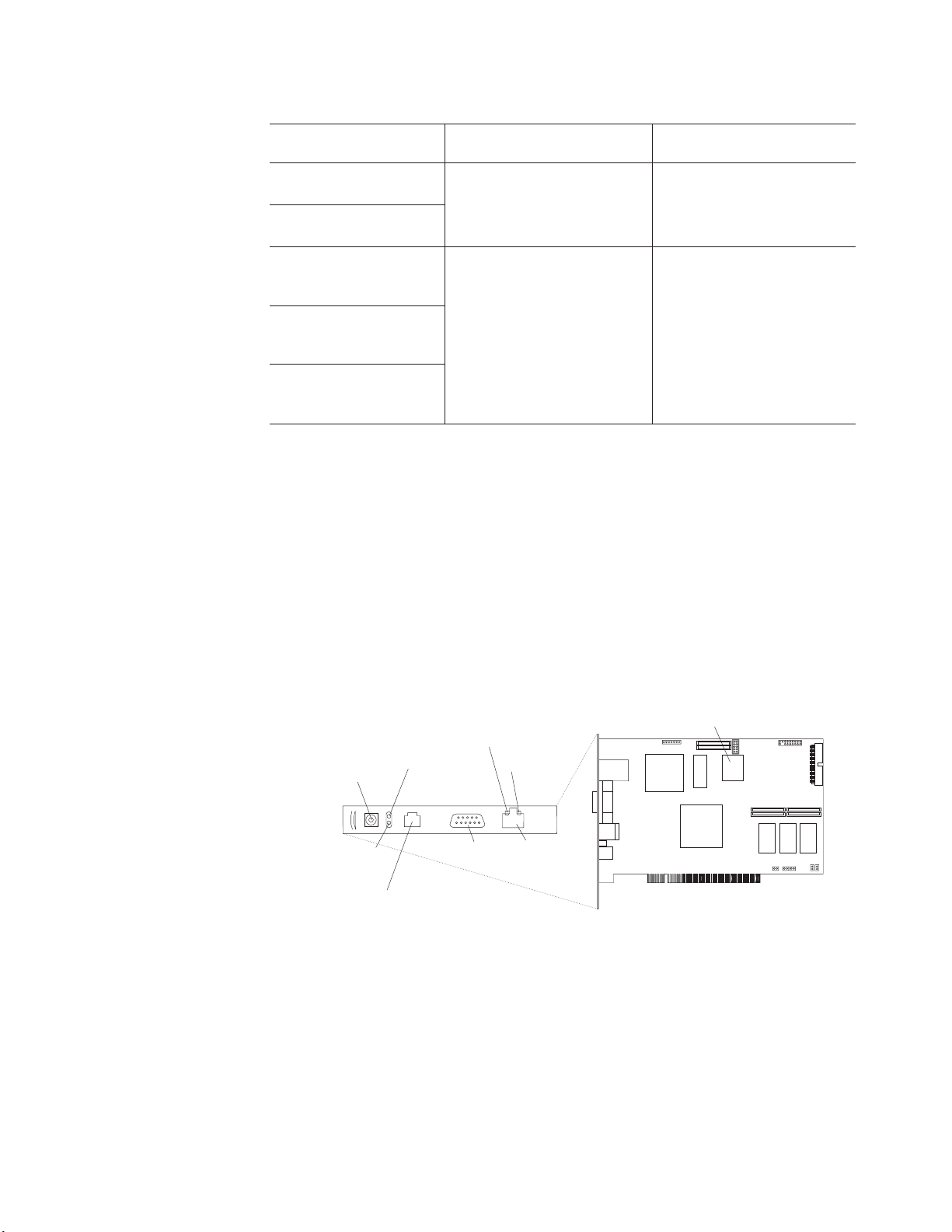
Check the Ethernet LEDs to ensure that the network connection is working. The
following illustration shows the locations of the LEDs.
Lithium
battery
External power
supply connector
Power LED
(green)
ASM Interconnect port
Ethernet activity
LED (green)
Error LED
(amber)
P
P
Serial
connector
(COM)
(RJ-14)
Ethernet link
LED (green)
Ethernet
connector
(RJ-45)
Ethernet activity LED
When the green Ethernet activity LED flashes, it indicates that there is
Ethernet activity.
Ethernet link LED
When the green Ethernet link LED is lit, it indicates that the Ethernet
cable is connected properly.
you want to use the serial port connection, continue with “Cabling the serial
If
(COM) port” on page 20; otherwise, go to “Configuring the adapter” on page 20.
Chapter 2. Configuring the server
19
Page 30

To
or
be
23
If
an
If
1.
2.
20
Cabling the serial (COM) port:
cable the serial (COM) port, connect a modem
null modem cable to the serial connector on the Remote Supervisor Adapter.
Then, continue with “Configuring the adapter.”
Configuring the adapter
This section describes how to enable remote access to the Remote Supervisor
Adapter and install ASM device drivers. These procedures assume that you have a
keyboard and pointing device attached to the server.
Enabling remote access to the adapter:
configured to enable remote access through the Ethernet connector or the serial
connector. Perform the configuration procedure for the interface method you want to
use.
Note: For detailed information about using the ASM Web interface and the
text-based interface, see the Remote Supervisor Adapter User’s Guide on
the IBM xSeries Documentation CD.
Table 2. Configuration tasks to enable remote access to the Remote Supervisor Adapter
User interface to Remote
Supervisor Adapter
ASM Web interface using
the HTTP protocol
Text-based user interface
using the Telnet protocol
Text-based user interface
using a modem or a null
modem
ASM Web interface using
point-to-point protocol
(PPP)
Text-based user interface
using the Telnet protocol
over PPP
Connection to Remote
Supervisor Adapter
LAN using the Ethernet port “Configuring the Ethernet
Serial (COM) port
The Remote Supervisor Adapter must
For the configuration
procedure, see
settings for Web-based remote
access”
“Configuring the serial port for
text-based remote access” on
page 22 and “Setting up
point-to-point protocol” on page
Configuring the Ethernet settings for Web-based remote access:
accessible, active, and configured Dynamic Host Configuration Protocol (DHCP)
server on the network, the host name, IP address, gateway address, subnet mask,
and DNS server IP address are set automatically. The default value should have no
effect on whether you have to do any other configuration. If you need to configure
the serial port, go to “Configuring the serial port for text-based remote access” on
page 22; otherwise, go to “Configuring the remote-control password” on page 25.
you do not have a DHCP server on the network, complete the following steps to
configure the Ethernet settings.
Note: For instructions to create the Remote Supervisor Utility CD, see “Setup
requirements” on page 16.
With the server turned off, insert the CD containing the EFI Remote Supervisor
Utility program into the drive; then, turn on the server. The utility starts
automatically, displaying the Remote Supervisor Utility window.
Use the Up Arrow and Down Arrow keys (↑ and ↓) to select Configuration
Settings; then, press Enter. The Configuration Settings window opens.
IBM xSeries 450 Type 8688: Hardware Maintenance Manual and Troubleshooting Guide
you have
Page 31

4.
IP
5.
6.
7.
8.
9.
3.
Use the arrow keys to select Ethernet Settings, and press Enter.
The Ethernet Settings window opens.
Note: The values in the window are only examples; your settings might be
different.
Use the arrow keys to navigate to each field. Your system administrator can
provide the information for the following fields:
Network Interface
The default setting is Enabled; verify that it is still set to Enabled.
Address
Type the IP address of the Remote Supervisor Adapter.
Subnet Mask
Type the subnet mask used by the Remote Supervisor Adapter. The
default value is 255.255.255.0.
Gateway
Type the IP address of the gateway.
Host Name
Type the hostname of the Remote Supervisor Adapter. The default
hostname is ASMA <burned-in MAC address>.
detailed information about the Ethernet settings, see the Remote
For
Supervisor Adapter User’s Guide on the IBM xSeries Documentation CD.
Change the DHCP Setting field to Disabled. The default setting is Enabled.
Press F6 to apply the change.
Press Esc. After the Warning window opens, press Enter to restart the Remote
Supervisor Adapter.
Press Esc to return to the Configuration Settings window. If you need to
configure the serial port, go to “Configuring the serial port for text-based
remote access” on page 22.
Press Esc to return to the Remote Supervisor Adapter Utility main window.
10.
Use the arrow keys to select Exit Utility from the menu, or press Esc to close
the Remote Supervisor Adapter Utility program.
11.
Remove the CD from the server. The server restarts automatically.
Chapter 2. Configuring the server
21
Page 32

If
1.
2.
3.
4.
5.
If
22
12.
you also want to configure the serial port, continue with “Configuring the
serial port for text-based remote access.” Otherwise, go to “Installing Advanced
System Management device drivers” on page 25.
Configuring
the serial port for text-based remote access:
Complete the
following steps to configure the Remote Supervisor Adapter serial port for access
using a modem or null modem. If you completed the procedure for configuring the
Ethernet port and the Configuration Settings window is open, go to step 4.
With the server turned off, insert the CD containing the EFI Remote Supervisor
Utility program into the drive, and turn on the server.
The utility starts automatically, displaying the Remote Supervisor Utility
window.
Use the Up Arrow and Down Arrow keys (↑ and ↓) to select Configuration
Settings, and press Enter. The Configuration Settings window opens.
Use the arrow keys to select Modem Settings, and press Enter. The Modem
Settings window opens.
Note: The values in the window are only examples; your settings might be
different.
Verify the following serial port values:
Baud Rate
The default is 57600. Make sure that the baud rate matches the baud
rate of the device you are connecting to the serial port on the Remote
Supervisor Adapter.
Dedicated to ASM
The default setting is Disabled. If you are using point-to-point protocol
(PPP), set this field to Enabled. If the value in this field is Enabled
when the server is restarted, the serial port remains dedicated to
system management and is not returned to the operating system.
Note: To use this serial port, you must first install the ASM device
drivers as described in “Installing Advanced System
Management device drivers” on page 25.
the serial port is shared with the operating system, it is dedicated to
the Remote Supervisor Adapter only while the server is turned off or
IBM xSeries 450 Type 8688: Hardware Maintenance Manual and Troubleshooting Guide
Page 33

6. If
7.
8.
9.
up
1.
2.
3.
4.
during POST. The port is returned to the operating system after POST
completes. You can view the port using the operating system or any
application. The Remote Supervisor Adapter takes over the port from
the operating system only when information about a critical event is
received. The Remote Supervisor Adapter dials out and transmits an
alert and keeps the port dedicated until the server is restarted. The
port is no longer available to the operating system or applications.
Parity The default setting is None.
Stop Bits
The default is 1.
Note:
The data bits value is preset to 8 and cannot be changed.
For detailed information about the serial port and modem settings, see the
Remote Supervisor Adapter User’s Guide on the IBM xSeries Documentation
CD.
you made changes to the serial port settings, press F6 to apply the change.
Press Esc to return to the Configuration Settings window. If you need to set up
point-to-point protocol, go to “Setting up point-to-point protocol.”
Press Esc to return to the Remote Supervisor Adapter Utility main window.
Use the arrow keys to select Exit Utility from the menu, or press Esc to close
the Remote Supervisor Adapter Utility program.
10.
Remove the CD from the drive. The Remote Supervisor Adapter restarts
automatically.
11.
Continue with “Setting up point-to-point protocol.”
Setting
point-to-point protocol:
The Remote Supervisor Adapter serial port
supports PPP. PPP enables TCP/IP communication over the serial port, which
enables Web-based management and TELNET sessions over a modem. To set up
PPP, complete the following steps. If you completed the procedure for configuring
the serial port and the Configuration Settings window is open, go to step 4.
With the server turned off, insert the CD containing the EFI Remote Supervisor
Utility program into the drive, and turn on the server.
The utility starts automatically, displaying the Remote Supervisor Utility
window.
Use the Up Arrow and Down Arrow keys (↑ and ↓) to select Configuration
Settings; then, press Enter. The Configuration Settings window opens.
Use the arrow keys to select PPP Settings, and press Enter. The PPP
Settings window opens.
Chapter 2. Configuring the server
23
Page 34

5.
IP
6.
7.
8.
9.
24
Note: The values in the window are only examples; your settings might be
different.
Use the arrow keys to navigate to each field. Verify the values in the following
fields:
Network Interface
The default setting is Disabled. Change this field to Enabled.
Address
The default value is 192.96.1.1. You can use the default value or
another value, but the server must be able to establish a connection to
that address. The default IP address (local and remote) is easily
reconfigurable.
Subnet Mask
The default value is 255.255.255.255.
Line Type
The value is set to PPP.
Remote IP Address
The default value is 192.96.1.2.
Authentication Protocol
The default is CHAP then PAP. Make sure that the value in this field
matches your client settings.
detailed information about the PPP settings, see the information about
For
configuring PPP access over a serial port in the Remote Supervisor Adapter
User’s Guide on the IBM xSeries Documentation CD.
Press F6 to apply the changes.
Press Esc. After the Warning message displays, press Enter to restart the
Remote Supervisor Adapter.
Press Esc to return to the Configuration Settings window. If you need to
configure the serial port, go to “Configuring the serial port for text-based
remote access” on page 22.
Press Esc to return to the Remote Supervisor Adapter Utility main window.
10.
Use the arrow keys to select Exit Utility from the menu, or press Esc to close
the Remote Supervisor Adapter Utility program.
11.
Remove the CD from the drive. The server restarts automatically.
IBM xSeries 450 Type 8688: Hardware Maintenance Manual and Troubleshooting Guide
Page 35

v
v
If
To
1.
2.
3.
4.
5.
6.
7. In
8.
9.
To
v
v
v
v
to
12.
Continue with “Installing Advanced System Management device drivers.”
Installing
Advanced System Management device drivers:
You must install the
ASM device drivers for the server to enable communication between the Remote
Supervisor Adapter and the server in which it is installed. You can obtain the most
current device drivers from http://www.ibm.com/pc/support/ on the World Wide Web.
Note: If you are installing device drivers manually, note the following requirements:
You must install the operating system on the server before you install the
ASM device drivers. For information about installing the operating system,
see the documentation that comes with the operating system.
Before installing the ASM device drivers for the Remote Supervisor
Adapter, stop any system-management application.
you install the ASM device drivers, go to “Configuring the remote-control
After
password” to set the remote-control password.
Configuring the remote-control password:
you want to use the remote-control
features of the Remote Supervisor Adapter ASM Web interface, you must configure
the remote-control password using the Configuration/Setup Utility program.
set up a remote-control password, complete the following steps:
Start the server and watch the monitor screen.
From the EFI Boot Manager startup options, select the Configuration/Setup
Utility program.
Use the Up Arrow and Down Arrow keys (↑ and ↓) to select System Security;
then, press Enter. The System Security window opens.
Select Remote Control Security Settings, and press Enter. The Remote
Control Security Settings window opens.
Type the remote-control password that you will use each time you log into the
remote-control features of the Remote Supervisor Adapter ASM Web Interface.
Select Save New Remote Control Password, and press Enter.
the System Security window, press Esc.
Select Save Settings, and press Enter.
Confirm your selection, and exit the Configuration/Setup Utility program.
10.
Continue with “Completing the configuration.”
Completing
the configuration:
complete the configuration of the Remote
Supervisor Adapter, see the Remote Supervisor Adapter User’s Guide on the IBM
xSeries Documentation CD. The tasks include the following:
Defining the login IDs and passwords
Selecting the events that will receive alert notification
Monitoring remote server status using the ASM Web interface or a text-based
user interface
Controlling the server remotely
you want to set up an ASM interconnect network and have not already done so,
If
continue with “Using the ASM interconnect network” on page 26. If you do not want
set up an ASM interconnect network, Remote Supervisor Adapter configuration is
now complete. To start managing the server remotely, see the Remote Supervisor
Adapter User’s Guide on the IBM xSeries Documentation CD.
Chapter 2. Configuring the server
25
Page 36

An
on
an
To
To
v
v
v
26
Using the ASM interconnect network
This section explains how to configure and connect the server to function within an
ASM interconnect network.
The ASM interconnect network can include as many as 12 individual ASM
connections in a single bus. These connections can include Remote Supervisor
Adapters, ASM processors, and ASM PCI adapters. When the clients and servers
are connected, they use the ASM interconnect network to share ASM resources,
information, and alerts among multiple servers without having to add additional
communications hardware or network interface adapters.
ASM interconnect network provides two levels of functionality. First, the ASM
interconnect network enables you to configure settings and to control the servers
where other Remote Supervisor Adapters, ASM processors, and ASM PCI adapters
the network reside. Second, the ASM interconnect network enables other
interconnect network devices to use the resources (Ethernet or modem) of other
Remote Supervisor Adapters, ASM processors, and ASM PCI adapters in the ASM
interconnect network for sending alerts. This interconnect network is used when
Remote Supervisor Adapters, ASM processors, or ASM PCI adapters cannot send
alert and must forward the information to another one of these devices to send
the alert.
Planning and cabling the interconnect network
support the most recent ASM features, a Remote Supervisor Adapter must be
the main gateway interconnect to the ASM interconnect bus if the bus also includes
servers with ASM PCI adapters or ASM processors. The Remote Supervisor
Adapter forwards the ASM information generated by the servers attached to the
ASM interconnect bus to other servers on the Ethernet network. The connected
ASM processors and ASM PCI adapters are managed through the new user
interface and Web browser access of the Remote Supervisor Adapter.
Note: To ensure the stability of the system, you must have the most current level of
firmware installed on the Remote Supervisor Adapter that is the main
interconnect gateway for the ASM interconnect network. The most current
level of firmware is available at http://www.ibm.com/pc/support/ on the World
Wide Web. For more information about updating firmware, see “Updating the
firmware” on page 39 and the Remote Supervisor Adapter User’s Guide on
the IBM xSeries Documentation CD.
You must connect an ASM Interconnect module to the Remote Supervisor Adapter
and to each xSeries 450 server that you connect to the ASM interconnect network
bus.
Attention: To avoid damage to the Ethernet connector on the Remote Supervisor
Adapter, do not plug the ASM Interconnect module into the Remote Supervisor
Adapter Ethernet connector.
connect the servers, note the following setup and configuration considerations:
Ensure that the ASM interconnect network is set up as a bus topology. You must
connect the servers to the ASM interconnect network in a series, with terminated
beginning and end points.
Ensure that the total combined length of all Ethernet cables connecting the
server in the ASM interconnect network does not exceed 91 m (300 ft).
Each Remote Supervisor Adapter, ASM PCI adapter, or ASM processor that is
connected to the ASM interconnect network bus counts as one connection. For
IBM xSeries 450 Type 8688: Hardware Maintenance Manual and Troubleshooting Guide
Page 37

If
If
example, if an ASM PCI adapter is installed in a server that has an ASM
processor, the processor and the adapter connect to each other using one ASM
interconnect connection, but the processor and the adapter count as two
connections on the ASM interconnect network bus.
Forwarding alerts
Remote Supervisor Adapters, ASM PCI adapters, and ASM processors that are
connected to an ASM interconnect network share resources and
system-management information. This section provides information on how alerts
are forwarded in the ASM interconnect network.
During normal operation, each Remote Supervisor Adapter, ASM processor, or ASM
PCI adapter on the ASM interconnect network communicates with the other
processors and adapters on the network. Processors or adapters that have a
modem or Ethernet connection notify the other processors and adapters that these
communications resources are available for use by other servers on the ASM
interconnect network. These resources are then used as ASM interconnect network
resources, enabling Remote Supervisor Adapters, ASM processors, or ASM PCI
adapters on the ASM interconnect network to send alerts using a modem or the
network, even if they do not have a modem or network connection physically
attached.
When alerts are generated, they are forwarded to the Remote Supervisor Adapter,
ASM processor, or ASM PCI adapter on the ASM interconnect network that has the
communication resources to forward the alert. If no system on the ASM interconnect
network meets the requirements, the alert is set for transmission if the connection
type is configured or becomes available later.
multiple modems or network connections exist in the ASM interconnect network,
you cannot specify which system will receive an alert or which will use its modem or
network connection to forward the alert. If an alert is forwarded to a Remote
Supervisor Adapter, ASM processor, or ASM PCI adapter that is unable to deliver
the alert (for example, the modem it is configured to use has failed or the network
cannot resolve the destination IP address), the processor or adapter attempts to
forward the alert to another system on the ASM interconnect network that has the
communication resources to forward the alert.
Alerts are typically sent once per connection type, but an alert is forwarded to
another interconnect device if the resources exist on other interconnect devices in
the network. For example, on a three ASM processor network where ASM
processor 1 generates a modem alert, but does not have a modem and the other
ASM processors have modems, the following might occur:
ASM processor 1 generates an alert and the modem is unplugged from ASM
processor 2 45 seconds prior to ASM processor 1 generating the alert, ASM
processor 1 forwards the alert to ASM processor 2, having previously determined
that ASM processor 2 has an available modem. When ASM processor 2 receives
the forwarded alert, it determines that a modem is attached to ASM processor 3
and forwards the alert. Therefore, depending on the time frame (45 seconds) within
which a resource (modem) fails, the alert might be forwarded multiple times until an
interconnect device can send the alert.
Connecting the ASM Interconnect module to the xSeries 450
The ASM Interconnect module connects the Remote Supervisor Adapter to the ASM
interconnect network. This module must be purchased separately.
Chapter 2. Configuring the server
27
Page 38

1.
2.
of
3.
28
To connect the ASM interconnect module to the Remote Supervisor Adapter,
complete the following steps.
Attention: To avoid damage to the Ethernet connector, do not plug the ASM
interconnect module into the Remote Supervisor Adapter Ethernet port.
Connect the ASM Interconnect module 1 to the Remote Supervisor Adapter
ASM interconnect (peer-to-peer) port 2. This port is on the edge of the
Remote Supervisor Adapter that is accessible from the rear of the server and is
labeled RS485.
Connect one or two Category 3 or Category 5 Ethernet cables to the other end
the ASM Interconnect module.
Continue with “ASM interconnect network configuration examples.”
ASM interconnect network configuration examples
The illustrations in this section show sample ASM interconnect network
configurations.
IBM xSeries 450 Type 8688: Hardware Maintenance Manual and Troubleshooting Guide
Page 39

The following illustration shows an Ethernet cable connecting the remote
administrator system to the Remote Supervisor Adapter that is installed in an
xSeries 450. Server 1 uses the LAN connection to forward system-management
data generated by the other xSeries 450s in the ASM interconnect network bus to
the remote system-management administrator.
Remote system
management administrator system
Ethernet
xSeries 450
Server 3
xSeries 450
Server 2
xSeries 450
Server 1
RS-485
terminator plug
Note: The ASM Interconnect module is connected to the RS485 port on the
back panel of the Remote Supervisor Adapter in each server.
RS-485
terminator plug
ASM
Interconnect
modules
Chapter 2. Configuring the server
29
Page 40

30
The following illustration shows a modem connected to the serial port of the
Remote Supervisor Adapter in the xSeries 450 on the left, a modem connected to
the serial port of the Remote Supervisor Adapter in the xSeries 450 on the right,
and a modem connected to the remote administrator system. Placing modems at
opposite ends of the ASM interconnect network bus ensures that if an ASM
interconnect connection in the bus fails, all of the servers on the ASM interconnect
network have access to a modem to forward system-management data to the
remote system-management administrator.
Remote system
management
administrator system
Modem
Modem
Note: A Remote
Supervisor Adapter is
required in each server.
Note: The ASM Interconnect module is connected to the RS485 port on the
back panel of the Remote Supervisor Adapter in each server.
xSeries 450
Modem
xSeries 450
xSeries 450
ASM
Interconnect
modules
IBM xSeries 450 Type 8688: Hardware Maintenance Manual and Troubleshooting Guide
Page 41

Configuring the Gigabit Ethernet controller
The Ethernet controllers are integrated on the I/O board. They provide an interface
for connecting to a 10-Mbps, 100-Mbps, or 1-Gbps network and provide full-duplex
(FDX) capability, which enables simultaneous transmission and reception of data on
the network. If the Ethernet ports in your server support auto-negotiation, the
controllers detect the data-transfer rate (10BASE-T, 100BASE-TX, or 1000BASE-T)
and duplex mode (full-duplex or half-duplex) of the network and automatically
operate at that rate and mode.
You do not need to set any jumpers or configure the controllers. However, you must
install a device driver to enable the operating system to address the controllers. For
device drivers and information about configuring the Ethernet controllers, see the
Resource CD that comes with your server. For updated information about
configuring the controllers, go to http://www.ibm.com/pc/support/ on the World Wide
Web.
The following illustration shows the Ethernet controller port assignments,
connectors, and LEDs.
Ethernet LED (port 0)
Ethernet LED (port 1)
Ethernet connector (port 1)
Ethernet connector (port 0)
Chapter 2. Configuring the server
31
Page 42

32
IBM xSeries 450 Type 8688: Hardware Maintenance Manual and Troubleshooting Guide
Page 43

If
If
A
A
v
v
v
If
1.
2. If
3. If
4. If
5.
6.
7.
©
Chapter 3. Diagnostics
This section provides basic troubleshooting information to help you resolve some
common problems that might occur with your server.
you cannot locate and correct the problem using the information in this section,
see Appendix A, “Getting help and technical assistance,” on page 195 for more
information.
General checkout
The server diagnostic programs are stored in the upgradeable electronically
erasable programmable read-only memory (EEPROM) on the I/O board and on the
Resource CD. These programs provide the primary methods of testing the major
components of the server.
you cannot determine whether a problem is caused by the hardware or by the
software, run the diagnostic programs to confirm that the hardware is working
properly.
Note: A single problem might cause several error messages. When this occurs,
work to correct the cause of the first error message. After you correct the
cause of the first error message, the other error messages usually will not
occur the next time you run the test.
failed server might be part of a shared hard disk drive cluster (two or more
servers sharing one or more external storage devices). Before you run diagnostics,
verify that the failing server is not part of a shared storage device cluster.
server might be part of a cluster if:
The server is identified as part of a cluster.
One or more external storage units are attached to the server and at least one of
the attached storage units is also attached to another server or unidentifiable
source.
One or more servers are located near the failing server.
the failing server is suspected to be part of a shared hard disk drive cluster, run
all diagnostic tests except those that test the storage unit (storage device residing in
the storage unit) or the storage adapter attached to the storage unit.
Notes:
For servers that are part of a shared hard disk drive cluster, run one test at a
time in looped mode. Do not run all tests in looped mode, because this could
enable the hard disk drive diagnostic tests.
multiple error codes are displayed, diagnose the first error code that is
displayed.
the server stops with a POST error, see “SAL/EFI messages” on page 150.
the server stops and no error is displayed, see “Undetermined problems” on
page 185.
For power supply problems, see “Power checkout” on page 74.
For safety information, see “Safety information” on page 197.
For intermittent problems, check the system-error log.
Copyright IBM Corp. 2003
33
Page 44

to
If
1.
2.
a. If
b. If
If
1.
2.
a. If
b. If
4.
5.
6.
7.
8.
9.
If
If
If
34
Follow the steps in this procedure to identify system problems.
001 IS THE SERVER PART OF A CLUSTER?
YES. Schedule maintenance for the system. Shut down all systems related
the cluster.
NO. Go to step 002.
002 IF THE SERVER IS NOT PART OF A CLUSTER:
the operating system is running, do the following:
Check the Light Path. Go to “Light Path Diagnostics feature” on page 36
for more information.
Check the service processor system-error logs.
the system-error log indicates a damaged field replaceable unit
(FRU), replace the FRU, and run the AMIDiag program to confirm
that the problem has been solved.
the system-error log does not indicate a damaged FRU, check the
Light Path.
003
the operating system is not running, do the following:
Check the Light Path. Go to “Light Path Diagnostics feature” on page 36
for more information.
Check the service processor system-error logs.
the error log indicates a damaged field replaceable unit (FRU),
replace the FRU, and run the AMIDiag program to confirm that the
problem has been solved.
the error log does not indicate a damaged FRU, see
“Undetermined problems” on page 185
3.
Turn off the server and all external devices.
Check all cables and power cords.
Set all display controls to the middle position.
Turn on all external devices.
Turn on the server.
Monitor the screen and the serial port for POST errors, and record any
POST error messages that are displayed on the screen. If an error is
displayed, look up the first error in the “SAL/EFI messages” on page
150.
When the EFI Boot Manager starts, select Diagnostic from the menu,
and press Enter to start the AMIDiag program.
DID THE DIAGNOSTIC PROGRAM START?
NO. Find the failure symptom in “Error symptoms” on page 176.
YES. Run the diagnostic programs. If necessary, see “Diagnostic programs,
error codes, and messages” on page 38.
you receive an error, see Chapter 6, “Symptom-to-FRU index,” on page
147.
the diagnostic programs were completed successfully and you still
suspect a problem, see “Undetermined problems” on page 185.
the server does not turn on, see “Error symptoms” on page 176.
IBM xSeries 450 Type 8688: Hardware Maintenance Manual and Troubleshooting Guide
Page 45

v
v
v
v
If a
v
38
v
1.
2.
Diagnostic tools overview
The following tools are available to help you identify and resolve hardware-related
problems:
POST error messages
The power-on self-test (POST) generates error messages to indicate the
detection of a problem. See “POST error codes and messages” for more
information.
System-error logs
The system-error log contains all the error messages that were issued during
POST. See “System-error logs” on page 36.
Light Path Diagnostics feature
Use the Light Path Diagnostics feature to identify system errors quickly (see
“Light Path Diagnostics feature” on page 36).
Diagnostic display
problem is detected with system power on or during initialization, an error
code might be present in the two-hex character diagnostic display on the
midplane board. See “Diagnostic display error codes” on page 181 for more
information.
Diagnostic programs and error messages
The AMIDiag program is the primary method of testing the major components of
the server. The AMIDiag program is stored in the EEPROM on the I/O board. You
can download the latest version of this program and copy it to a CD so that you
can update the AMIDiag program. See “Starting the AMIDiag program” on page
for more information.
The diagnostic program for the Ethernet controller is on the Resource CD. For
instructions about using this CD, see “Troubleshooting the Ethernet controller” on
page 75.
Product support page
The IBM Web site has up-to-date information about IBM xSeries products,
services, and support at http://www.ibm.com/eserver/xseries/ on the World Wide
Web.
You can find service information for your IBM products, including supported
options, at http://www.ibm.com/pc/support/.
POST error codes and messages
When you turn on the server, it performs a series of tests to check the operation of
server components and some of the options installed in the server. This series of
tests is called the power-on self-test, or POST.
Notes:
This server does not produce beep codes.
Depending on system configuration, POST might run for several minutes before
the video console is enabled. During this time, POST operation is indicated by
the flashing blue locator LED on the front panel. Diagnostic display error codes
track the startup progress until video is enabled.
POST finishes without detecting any problems, the EFI Boot Manager screen
If
appears. If POST detects a problem, an error message will be sent to either the
serial port or the display screen. See “SAL/EFI messages” on page 150 for more
information.
Chapter 3. Diagnostics
35
Page 46

36
System-error logs
The system-error log contains all messages issued during system initialization or
normal system operation.
You can view the contents of the system-error log from the Configuration/Setup
Utility program or from the service processor. To view error logs from the
Configuration/Setup Utility program, start the Configuration/Setup Utility program;
then, select Error Logs from the main menu. See “Starting the Configuration/Setup
Utility program” on page 12 for more information.
You can also use the error-log viewer in the AMIDiag program. For information
about viewing diagnostic program error logs from the AMIDiag program, see
“Error-log viewer” on page 42.
Light Path Diagnostics feature
The Light Path Diagnostics panel is inside the Light Path Diagnostics drawer on the
front right of the server. When you press on the front of the Light Path Diagnostics
drawer, the Light Path Diagnostic panel is exposed.
The following illustration shows the location of the diagnostics panel. See “The
diagnostics panel” on page 37 for information about identifying problems using the
Light Path Diagnostic LEDs.
The system-error LED on the operator information panel is lit when certain system
errors occur. If the system-error LED on the server is lit, one or more LEDs inside
the server might be lit. Use the Light Path Diagnostics panel to identify the type of
IBM xSeries 450 Type 8688: Hardware Maintenance Manual and Troubleshooting Guide
Page 47

To
To
is
To
A
If a
error that occurred, and see “Light Path LED errors” on page 147 to help determine
the cause of the error and the action you should take.
view the LEDs on the various main boards, look at the board indicated by the
diagnostic panel.
acknowledge a system error but not take immediate action, press the REMIND
button, and place the Light Path Diagnostics feature in Remind mode. The
system-error LED flashes in Remind mode. If a new failure occurs, the system-error
LED is lit again.
The diagnostics panel
The diagnostics panel should be the first place you look for help with identifying
problems. If a system error occurs, the system-error LED on the front of this panel
lit. Press the front of the panel to open the diagnostics panel, and look for any lit
LEDs. These lit LEDs can help you identify the possible cause of the error. Make a
note of any LEDs that are lit, and then close the panel.
LEDs on the top of the server
You can also use the LEDs on the top of the server to find an error. If the BOARD
LED on the diagnostics panel is lit, pull the server out, and view the top cover. In
the center of the top cover is a set of six LEDs and the system service labels. The
numbers next to the LEDs correspond to the numbers on the system service label.
Note the lit LED, and see the numbered block on the system service label that
corresponds to the lit LED. Then, follow the instructions, if any, in the numbered
block.
LEDs on the system boards
locate the actual component that caused the error, locate the lit LED next to that
component.
For example:
system error has occurred, and you have noted that the CPU LED is lit on the
diagnostics panel. Referring to the LEDs on the top cover, you see that LED 2 is lit.
You then locate the panel on the system service label with the number 2 on it. In
this case, the instructions in the panel tell you that the problem occurred with one of
the microprocessors. Follow the instructions to remove the processor-board
assembly. See “Processor-board assembly” on page 119. Located on the circuit
board is the light-path capacitor switch. Press and hold the switch until you locate
the lit LED next to the defective microprocessor. Follow the instructions in
“Microprocessor and power module” on page 121 and “Installing and replacing a
microprocessor and power module” on page 100 to remove and replace the
microprocessor.
For more information about LEDs and connectors, see “Connector and LED
locations” on page 80.
Diagnostic display
character diagnostic display on the midplane board might show an error code. See
“Midplane board connectors and LEDs” on page 84 and “Diagnostic display error
codes” on page 181 for more information.
problem is detected with system power on or during initialization, the two-hex
Chapter 3. Diagnostics
37
Page 48

be
is
it is
1.
2.
3.
38
Diagnostic programs, error codes, and messages
Diagnostic error messages indicate that a problem exists. They are not intended to
used to identify a failing part. Troubleshooting and servicing of complex
problems that are indicated by error messages should be performed by trained
service personnel.
Sometimes the first error to occur causes additional errors. In this case, the server
displays more than one error message. Always follow the suggested action
instructions for the first error message that appears.
Chapter 6, “Symptom-to-FRU index,” on page 147 contains the error codes that
might appear in the detailed test log and summary log when the diagnostic
programs are run.
Text messages
The diagnostic text message format is as follows:
Function Name: Result (test specific string)
where:
Function Name
the name of the function being tested when the error occurred. This
corresponds to the function code (fff) shown in the error code format in the
previous section.
Result
can be one of the following:
Passed
Failed
Aborted
Starting the AMIDiag program
The AMIDiag program is stored in the EEPROM of the server. You can download
the latest version from http://www.ibm.com/eserver/xseries/ on the World Wide Web.
Starting the AMIDiag program from the server
Complete the following steps to start the AMIDiag program:
Turn on the server, and watch the screen.
This result occurs when the diagnostic test is completed
without any errors.
This result occurs when the diagnostic test discovers an
error.
This result occurs when you stop the diagnostic test before
complete.
Note: To run the AMIDiag program, you must start the server with the highest
level password that is set. That is, if an administrator password is set,
you must type the administrator password, not the user password, to run
the diagnostic programs.
When the EFI Boot Manager appears on the screen, select Diagnostic, and
press Enter.
When the AMIDiag program screen appears, select the test you want to run
from the menu that appears, and follow the instructions on the screen.
IBM xSeries 450 Type 8688: Hardware Maintenance Manual and Troubleshooting Guide
Page 49

a.
b. If
c.
If
To
To
1.
2.
3.
1.
to a
2.
3.
4.
5.
6.
7.
8.
Notes:
Press F1 while running the AMIDiag program to obtain help information.
Press F1 from within a help screen to obtain online documentation from
which you can select different categories. To exit from the help information
and return to where you left off, press Esc.
the server stops during testing and you cannot continue, restart the server
and try running the AMIDiag program again. If the problem remains, replace
the component that was being tested when the server stopped.
When you exit the AMIDiag program, the server resets automatically. If the
server does not reset automatically, manually reset the server before starting
the operating system.
the diagnostic programs do not detect any hardware errors but the problem
If
persists during normal server operations, a software error might be the cause. If
you suspect a software problem, see ″Software problems″ at “Error symptoms” on
page 176 and the information that comes with the software package.
Updating the firmware
you have downloaded the latest version of the AMIDiag program from the World
Wide Web, you can create a CD or save it to a valid file system on your server so
that you can update the AMIDiag program on the server.
Before you can create a CD, you might need to enable the CD creating feature. For
instructions to enable the CD creating feature using Microsoft Windows Server
2003, see “Setup requirements” on page 16. For instructions using another
operating system, see the documentation for the operating system.
create a CD with the latest version of the AMIDiag program, unzip the file that
you downloaded from the World Wide Web, and copy it to a CD.
use the service processor to update SAL/EFI, AMIDiag, or service processor
firmware, complete the following steps:
Open the Remote Supervisor Adapter Web browser, and click Firmware
Update.
Click Browse, and select flash2.efi; then, click Update. A loader popup
window is displayed.
When the Confirm Firmware Update window displays, click Continue. A
message indicating that the update has completed displays when the update is
finished.
update the firmware from the EFI Shell, complete the following steps:
To
Unzip the file you downloaded, and save all the components of the file package
valid file system.
From the EFI Boot Manager, select EFI Shell [Built-In], and press Enter.
Locate the file system on which the file you downloaded was saved, and type cd
fsn:, where n is the file system number where the file is saved.
Locate the directory where the file is saved, and go to that directory.
Type flash2, and press Enter. A menu is displayed.
Select Update System Firmware, and press Enter. A Warning screen is
displayed.
Press Enter to continue. The Firmware Update Options Menu is displayed.
Select Normal Flash - All Subsystems, and press Enter. Follow the
instructions on the screen.
Chapter 3. Diagnostics
39
Page 50

F1
F2
F3
F4
F5
F6
F7
F8
F9
40
AMIDiag menus
9.
Restart the server.
The following figure shows the AMIDiag main menu:
Press the Up Arrow (↑) or Down Arrow (↓) keys to select a menu choice, and press
Enter. Press the Right Arrow (→) or Left Arrow (←) keys to display a different
AMIDiag menu.
Using AMIDiag keys
The following table shows the AMIDiag keys and a brief description of their function.
Key
Esc
Enter
F10
Description
Halt a currently running test. Exits the AMIDiag program if no test is running.
Run the selected AMIDiag test.
Display Help screens.
Edit batch parameters.
Load batch parameters.
Save batch parameters.
Select or deselect the current test.
Select or deselect the tests on a specific AMIDiag menu.
Select or deselect all AMIDiag tests.
Select or deselect all tests necessary to run a system quick test.
Display a list of the AMIDiag function keys.
Run the selected test or tests.
IBM xSeries 450 Type 8688: Hardware Maintenance Manual and Troubleshooting Guide
Page 51

To
Do
1.
2.
1.
2.
1.
2.
1.
2.
3.
1.
2.
3.
1.
2.
3.
1.
2.
3.
of
a
To
1.
2.
3.
4.
Running AMIDiag tests
run this test or test group...
Run all AMIDiag tests.
Run a complete overall system quick
test .
Run all processor board diagnostic tests.
Run all memory diagnostic tests.
Run all IDE drive diagnostic tests.
Run all USB diagnostic tests.
Run all video diagnostic tests.
Run all serial, expansion port, and ASM
diagnostic tests.
Enable logging of test session.
Exit the AMIDiag program.
the following
Press F7, then F10.
Press F8, then F10.
Select System, and press Enter.
Press F6, then press F10.
Select Memory, and press Enter.
Press F6, and then press F10.
Select IDE, and press Enter.
Press F6, and then press F10.
Select USB, and press Enter.
Press F6.
Press F10.
Select Video, and press Enter.
Press F6.
Press F10.
Select the Misc. menu, and press Enter.
Press F6.
Press F10.
Select Options, and press Enter.
Select Generate Reports, and press Enter.
Select the output device, and press Enter.
Note: Logging to a file requires a writeable
file system to be available from the EFI
environment.
Press Esc, and select Yes at the prompt.
Running the AMIDiag program in Batch Mode
When your server is experiencing an intermittent problem that no diagnostic
software test has been able to identify, run AMIDiag tests over an extended period
time. Many server problems (especially memory problems) are not evident when
test is run only once. You can use the AMIDiag program to run diagnostic tests on
only a certain part of the server, a specific part of memory, or a specific part of a
disk drive. You can also use the AMIDiag program to build script (.INI) files that
contain test configuration information. After you have created an AMIDiag script file,
you can run the diagnostic tests listed in the .INI file automatically.
run the AMIDiag program in batch mode, complete the following steps:
Select the AMIDiag tests to be run.
Select the test parameters, such as the drives and the I/O ports. These
parameters differ for each test.
Press F10 to run the tests.
Save the current AMIDiag test configuration to a .INI file. You can then run this
set of AMIDiag tests at any time.
Chapter 3. Diagnostics
41
Page 52

If
To
If
1.
2.
3.
4.
1.
2.
3.
1.
2.
3.
42
Error-log viewer
you have enabled logging with the Generate Report option, you can display the
log while still running the AMIDiag program. The AMIDiag error log contains all
diagnostic errors that the AMIDiag program has found during the current AMIDiag
session. The error-log viewer offers some text search capability.
display the error log, select Display Error Log File on the AMIDiag Options
menu. Type the name of the error log file. The default error log filename is
amidiag.log. The AMIDiag error log file will be displayed.
you get a message that says that the log file is damaged, complete the following
steps to correct the problem:
From the main menu, select Options, and press Enter.
Select Generate Report, and press Enter.
Select Report Destination, and press Enter.
Note: You must be able to write to the file system to which you are saving the
report.
Select File, and press Enter.
access Help for more information about an error, browse to the error that you
To
want to see in the error window (on the right side of the screen), and press F1.
Quitting tests
Press Esc to quit the testing process. Testing stops after any test in progress has
been completed.
System diagnostic tests
This section describes individual system diagnostic tests.
Note: Each test on the System menu can generate error codes. For system-error
codes, see “System-error codes” on page 159.
Processor test
Use the processor test to make sure that all microprocessors are functioning
properly.
Use the CPU Functionality Test to make sure that microprocessors in the server are
operating correctly and efficiently in all address modes. To run the CPU
Functionality Test, complete the following steps:
From the AMIDiag main menu, select System, and press Enter.
Select Processor Test, and press Enter.
Select CPU Functionality Test, and press Enter.
the CPU Speed Test to check the microprocessor speed. When you run this
Use
test, the screen displays the expected processor speed and the actual
microprocessor clock speed. To run the CPU Speed Test, complete the following
steps:
From the AMIDiag main menu, select System, and press Enter.
Select Processor Tests, and press Enter.
Select CPU Speed Test, and press Enter.
IBM xSeries 450 Type 8688: Hardware Maintenance Manual and Troubleshooting Guide
Page 53

a.
b.
c.
1.
2.
3.
1.
2.
3.
1.
2.
to
1.
2.
4.
Set the test parameters:
Select YES for the CPU Speed Comparison, and press Enter.
Select Expected CPU Speed, and press Enter.
Select Run Test parameters, and press Enter.
make sure the system configuration is not damaged, complete the following
To
steps:
From the AMIDiag main menu, select System, and press Enter.
Select Processor Tests, and press Enter.
Select CMOS Validity Test, and press Enter.
make sure that the PCI adapter slots are functioning correctly, complete the
To
following steps:
From the AMIDiag main menu, select System, and press Enter.
Select Processor Tests, and press Enter.
Select PCI Test, and press Enter.
System Board Test
Select this choice to run a DMA controller test or a CMOS validity test.
DMA controller test:
This test is a series of read and write tests on the memory
address registers and page registers of direct memory address (DMA) controllers 1
and 2. The DMA controller manages the flow of information directly to and from
system memory and an ″intelligent″ peripheral device, without passing through the
microprocessor. On error, the AMIDiag program displays the register number, data
written, and data read. To perform this test, complete the following steps:
From the main menu, select System, and press Enter.
Select DMA Controller Test, and press Enter.
CMOS
Validity Test:
Use this test to check the validity of the data in CMOS RAM,
make sure that the CMOS RAM checksums are correct, and to make sure that
the battery is in good condition. To perform this test, complete the following steps:
From the main menu, select System, and press Enter.
Select CMOS Validity Test, and press Enter.
PCI System Test
Use the PCI System Test to make sure that the PCI bus and all PCI devices in the
server are working properly.
Multiprocessor Test
Select this test when running the AMIDiag program in a server that has more than
one microprocessor. This test performs a variety of diagnostic tests on all
microprocessors. To perform this test, select Multiprocessor Test from the System
menu, and press Enter. Follow the directions on the screen.
Chapter 3. Diagnostics
43
Page 54

v
v
1.
2.
3.
1.
2.
3.
1.
2.
3.
1.
2.
3.
44
Memory diagnostic tests
Use the memory diagnostic tests to make sure that the memory board and installed
memory are properly seated and functioning correctly. You can test all memory and
the memory board, or you can isolate a single memory bank to verify that it
functions correctly. The following test modes are available:
Quick test runs a single test pattern through the entire free, installed memory
space of the banks selected.
Full test runs 18 patterns, including pseudo-random patterns through the entire
free, installed memory space of the banks selected.
run the Quick Memory Test over all memory banks, complete the following steps:
To
From the AMIDiag main menu, select Memory, and press Enter.
Select Quick Memory Test, and press Enter.
Select All Banks, Quick Test, and press Enter.
To run full diagnostic tests over all memory banks, complete the following steps:
From the AMIDiag main menu, select Memory, and press Enter.
Select Full Memory Test, and press Enter.
Select All Banks, Full Test, and press Enter.
To run the Quick Memory Test over a single memory bank, complete the following
steps:
From the AMIDiag main menu, select Memory, and press Enter.
Select Quick Memory Test, and press Enter.
Select the individual bank you want to test or select Bank n, Quick Test, and
press Enter.
run the Full Memory Test over a single memory bank, complete the following
To
steps:
From the AMIDiag main menu, select Memory, and press Enter.
Select Full Memory Test, and press Enter.
Select the individual banks you want to test or select Bank n, Full Test, and
press Enter.
IDE device diagnostic tests
The IDE device diagnostic tests work only with CD-ROM, DVD, and removable
devices that use the ATAPI interface.
IBM xSeries 450 Type 8688: Hardware Maintenance Manual and Troubleshooting Guide
Page 55

v
a
To
1.
2.
To
1.
2.
A
To
1.
2.
3.
v
v
IDE CD-ROM tests
Use the IDE CD-ROM tests to make sure that the IDE CD-ROM drive is functioning
properly. You can test the functionality of the CD-ROM drive tray and the data and
audio read functions of the CD-ROM drive. The IDE CD-ROM tests include the
following:
IDE CD Tray Test
Select this test to make sure that the CD-ROM drive auto-eject feature can eject
CD. The CD tray should open and close.
run the CD tray test for an IDE CD-ROM drive, complete the following steps:
From the main menu, select IDE, and press Enter.
Select CD Tray Test, and press Enter.
IDE CD Data Test
v
Use the IDE CD data test to make sure that the CD-ROM drive is reading
correctly. This test reads all logical blocks on a CD if the starting and ending
block are not specified. Place any CD in the CD-ROM drive before running this
test, and follow the screen instructions. This test does not play audio CDs.
run the IDE CD data test to diagnose an IDE CD-ROM drive, complete the
following steps:
From the main menu, select IDE, and press Enter.
Select CD Data Test, and press Enter.
IDE CD Audio Test
v
speaker must be attached to the CD-ROM drive before running this test. This
test plays all logical blocks if the starting and ending block are not specified.
run the IDE CD audio test, complete the following steps:
Place an audio CD in the CD-ROM drive.
From the main menu, select IDE, and press Enter.
Select CD Audio Test, and press Enter.
the IDE CD test error codes, see “IDE CD test error codes” on page 161.
For
IDE DVD tests
The IDE DVD-ROM drive tests include the following:
IDE DVD Seek Test
Select this test to make sure that the DVD-ROM drive can seek to all sectors of
the DVD. You can change the size to seek by adjusting the Block Interleave
parameter value.
IDE DVD Read Test
Select this test to make sure that the DVD-ROM drive can read to all sectors of
the DVD. This test works with both encrypted and unencrypted DVDs.
For the IDE DVD-ROM drive test error codes, see “IDE DVD-ROM drive test error
codes” on page 164.
Chapter 3. Diagnostics
45
Page 56

v
v
1.
2.
a
v
v
v
v
v
v
v
v
v
46
ATAPI removables test
This test verifies that the removable disk drive, such as an Iomega ZIP drive, is
operating correctly. The tests include:
Format test
The format test verifies that the removable drive is properly formatted for
operation.
Attention: This test formats the media in the device being tested. Use this test
only if you want to format the media.
Write test
This test verifies the ability of the removable disk drive to write data correctly to a
disk. Use a disk that you know is good for this test. This test is normally hidden
from view because it erases the data on the disk. To make this menu item
viewable so that you can run this test, complete the following steps:
From the AMIDiag main menu, select Options, and press Enter.
Select Toggle Hidden Test Display, and press Enter.
Attention: This test erases all data on the disk.
Select the drive or drives to be tested, and run the test.
3.
v
Read test
Use this test to verify the ability of the removable media drive to read data
correctly in both block and random sequential format from a removable disk. Use
disk that you know is good for this test. Select the drive or drives to be tested,
and run the test. You can select the starting and ending clocks of data to be
read, or you can select the percentage of the drive to be read in a sequential or
random order. You can also run a random or sequential read test.
Seek test
Use this test to verify the ability of the removable media drive to seek blocks of
data sequentially or randomly. Select the test parameters, and run the test. You
can specify the number of times this test is to be run (repeat count), or you can
specify Quick Test to test only 1% of the disk.
Eject test
Use this test to verify that the auto-eject feature of the removable media drive is
working properly. You can set the Execution Count parameter to run this test a
number of times. Select the test parameters, and select Continue to run the test.
For the ATAPI removables test error codes, see “ATAPI removables test error
codes” on page 162.
SCSI diagnostic tests
The AMIDiag program tests all SCSI devices installed in your server. The SCSI
tests detect and test a combination of up to 120 SCSI hard disk drives.
SCSI diagnostic tests consists of the following tests:
SCSI Disk Buffer Test
SCSI Disk Self Diagnostic Test
SCSI Disk Read Test
SCSI Disk Write Test
SCSI Disk Format Test
SCSI Disk Spin Down Test
SCSI Disk Quick Test
IBM xSeries 450 Type 8688: Hardware Maintenance Manual and Troubleshooting Guide
Page 57

To
1.
2.
do
To
1.
2.
For the SCSI test error codes, see “SCSI test error codes” on page 164.
SCSI Disk Buffer Test
This test writes logical blocks of data to the internal buffer on the disk drive. The
same logical blocks of data are then read from the drive buffer and compared to the
original data. If the SCSI hard disk drive does not have an internal buffer, you
cannot select this test.
SCSI Disk Self Diagnostic Test
Select this choice to run the diagnostic tests on the SCSI disk drive.
run the test, complete the following steps:
Select SCSI Disk Self Diagnostic Test, and press Enter.
Choose the parameters on the screen, and select Continue.
Note: You cannot quit the SCSI Disk Self Diagnostic Test. You must wait until
the entire disk self test completes.
SCSI Disk Read Test
Use this test to make sure that the SCSI drive is reading correctly. This test
sequentially and randomly reads logical blocks from the SCSI hard disk drive. If you
not specify a starting and ending block number, block 0 through the last block
are tested.
run the SCSI disk read test, complete the following steps:
From the main menu, select SCSI, and press Enter.
Select SCSI Disk Read Test, and press Enter. A default parameter screen
appears.
Chapter 3. Diagnostics
47
Page 58

4.
so
1.
2.
1.
2.
48
3.
Set the parameters that you want.
Parameter
overall %
Description
Specifies the drivewise % or common % as set for
each drive. If Drivewise is selected, the drive
parameters are specified for each drive used. If
Common is selected, all drive parameters use the %
parameters, which are entered in the % for Common
fields. This reduces the need to set each drive
parameter if the server has a large number of drives.
Common:
SCSI Disk n
Use the term % to specify all drives
Specify an individual drive parameter.
Select Continue, and press Enter.
start and end block number fields are 0 and the last block on the disk or the
The
values set the last time this test was run. As the test runs, the current block
number, number of blocks tested, and number of blocks left are updated. Also, the
block tested is marked with a different character. The random test is performed on
the specified percentage of blocks between the specified start and end blocks.
SCSI Disk Write Test
Use this test to verify the ability of the SCSI disk drive to write data correctly to a
disk. Use a disk that you know is good for this test. This test is normally hidden
from view because it erases the data on the disk. To make this menu item viewable
that you can run this test, complete the following steps:
From the AMIDiag main menu, select Options, and press Enter.
Select Toggle Hidden Test Display, and press Enter.
Attention: This test erases all data on the disk.
Select the drive or drives to be tested, and run the test.
3.
SCSI Disk Format Test
Use this test to verify that the SCSI device is properly formatted for operation. This
test is normally hidden from view because it erases the data on the disk. To make
this menu item viewable so that you can run this test, complete the following steps:
From the AMIDiag main menu, select Options, and press Enter.
Select Toggle Hidden Test Display, and press Enter.
Attention: This test formats the media in the device being tested. Use this test
only if you want to format the media.
SCSI Disk Spin Down Test
This test issues a spin down command to the disk being tested.
Note: This action cannot be reversed easily without restarting the server.
SCSI Disk Quick Test
Use this test to perform an abbreviated read test on all SCSI disks installed in the
server.
IBM xSeries 450 Type 8688: Hardware Maintenance Manual and Troubleshooting Guide
Page 59

v
v
To
1.
2.
3.
a
To
1.
2.
To
1.
2.
SCSI CD-ROM tests
Use the SCSI CD-ROM tests to diagnose SCSI CD-ROM drive functions. SCSI
CD-ROM tests include the following subtests:
SCSI CD-ROM Buffer Test
Use this diagnostic test to make sure that the memory buffer on the CD-ROM
drive is working correctly.
SCSI CD-ROM Self Test
Select this choice to run the diagnostic tests on the disk.
run the test, complete the following steps:
From the main menu, select SCSI, and press Enter.
Select SCSI CD-ROM Self Diagnostics Test, and press Enter.
Select the parameters on the screen; then, select Continue, and press Enter.
Note: You cannot quit this test. You must wait until the entire test completes.
SCSI CD-ROM Tray Test
v
Select this test to make sure that the CD-ROM drive auto-eject feature can eject
CD. The CD tray should open and close.
test the CD-ROM drive tray, complete the following steps:
From the main menu, select SCSI, and press Enter.
Select SCSI Tray Test, and press Enter.
v
SCSI CD-ROM Read Test
Select this test to make sure that the CD-ROM drive can read to all sectors of
the CD. This test supports multi-format CDs with data and audio tracks, but it
fails if an audio CD is placed in the drive.
run the SCSI CD-ROM Read test, complete the following steps:
From the main menu, select SCSI, and press Enter.
Select SCSI CD-ROM Read Test, and press Enter. A parameter screen
appears:
Select SCSI Disk
Select SCSI Disk
Overall % Parameters 100
Overall % Parameters
SCSI Disk 0
SCSI Disk 0
CONTINUE
CONTINUE
Parameter
overall %
Common:
SCSI CD-ROM n
SCSI CD-ROM Read Test
SCSI CD-ROM Read Test
Test CDROM0
Test CDROM0
Start Block
Start Block
End Block
End Block
Sequential Test
Sequential Test
Random Test
Random Test
CONTINUE
CONTINUE
100
Description
Specifies drivewise % as set for each drive.
Use the term % to specify all drives
Specify an individual drive parameter.
: YES
: YES
: 000000000
: 000000000
: 002028000
: 002028000
Chapter 3. Diagnostics
49
Page 60

If
to
3.
To
1.
2.
3.
v
v
50
In the Sequential Test or Random Test, you are prompted for the
percentage of the drive to be tested.
Sequential Test
Sequential Test
Sequential Test : YES
Sequential Test
% to test : 100
%totest
CONTINUE
CONTINUE
: YES
:100
the starting and ending block are not specified, this test reads from block 0
the last block. The random test is performed on the specified blocks
between the start and end blocks.
Choose a percentage, select CONTINUE, and press Enter.
SCSI CD-ROM Play Test
v
Use this test to make sure that the CD-ROM drive can play audio CDs.
run the SCSI CD-ROM Play test, complete the following steps:
Attach a speaker to the CD-ROM drive, and insert an audio CD in the
CD-ROM drive.
From the main menu, select SCSI, and press Enter.
Select SCSI CD-ROM Play Test, and press Enter. A default parameter
screen appears:
Select SCSI Disk
Select SCSI Disk
Overall % Parameters 100
Overall % Parameters
SCSI Disk 0
SCSI Disk 0
CONTINUE
CONTINUE
Parameter
overall %
Common:
SCSI CD-ROM n
100
Description
Specifies drivewise % as set for each drive.
Use the term % to specify all drives
Specify an individual drive parameter.
The following appears if you specify an individual drive:
SCSI CD-ROM Play Test
SCSI CD-ROM Play Test
Test CDROM0
Test CDROM0
Start Block
Start Block
End Block
End Block
CONTINUE
CONTINUE
: YES
:YES
: 000000000
: 000000000
: 020280000
: 020280000
SCSI Tape Test
Use the SCSI Tape Test to diagnose functions of a SCSI tape device. The SCSI
Tape tests include the following:
SCSI Tape Buffer Test
This test writes logical blocks of data to the internal buffer on the tape drive. The
same logical blocks of data are then read from the tape drive buffer and
compared to the original data. If the tape drive does not have an internal buffer,
you cannot select this test.
SCSI Tape Read Test
Use this test to make sure that the SCSI tape drive is reading correctly. This test
reads sequential logical blocks from the SCSI tape. With default parameters, this
IBM xSeries 450 Type 8688: Hardware Maintenance Manual and Troubleshooting Guide
Page 61

To
1.
2.
A
3.
If
To
1.
2.
test requires fully written media to be installed in the device being tested.
Partially written media will result in a read error at the end of data. If only blank
media is available, use the SCSI Tape Write Test to write a test pattern onto the
blank media.
run the SCSI Tape Read Test, complete the following steps:
From the main menu, select SCSI, and press Enter.
Select SCSI Tape Read Test, and press Enter. A default parameter screen
appears:
Select SCSI Disk
Select SCSI Disk
Overall % Parameters 100
Overall % Parameters
SCSI Disk 0
SCSI Disk 0
CONTINUE
CONTINUE
100
Parameter
overall %
Common:
SCSI Tape n
Description
Specifies drivewise % as set for each drive.
Use the term % to specify all drives
Specify an individual drive parameter.
The following screen appears when you specify an individual drive:
SCSI Tape Read Test
SCSI Tape Read Test
Test Tape 0
Test Tape 0
Start Block
Start Block
End Block
End Block
CONTINUE
CONTINUE
: YES
:YES
: 000000000
: 000000000
: 002028000
: 002028000
prompt for the percentage of the drive to be tested appears.
Specify the percentage of the drive to be tested, select CONTINUE, and
press Enter.
the tape is not positioned at the beginning of the starting block, a tape
rewind command is issued before the test begins.
v
SCSI Tape Rewind Test
Use this test to make sure that the SCSI tape drive can rewind a tape.
run the SCSI tape rewind test, complete the following steps.
Note: A fully written tape must be installed to run this test.
From the main menu, select SCSI, and press Enter.
Select SCSI Tape Rewind Test, and press Enter.
SCSI Tape Write Test
v
Use this test to verify the ability of the SCSI tape drive to write data correctly to a
tape. Use a tape that you know is good for this test. This test is normally hidden
from view because it erases the data on the tape. Select the tape drives to be
tested, and run the test.
Attention: This test erases all data on the disk.
Video diagnostic tests
Select this choice to run diagnostic tests on the display and the video controller.
Chapter 3. Diagnostics
51
Page 62

1.
2.
as
To
1.
2.
80 x 25
in
40 x 25
52
To diagnose video display problems, complete the following steps:
From the main menu, select Video, and press Enter.
Select Video Memory Test, and press Enter.
For the video test error codes, see “Video test error codes” on page 167.
Running video tests
The video test you run depends on the type of monitor installed on your server.
Video Monitor Test
These tests verify the video controller output in addition to the communication
between the controller and the display device.
Attribute Test:
Use this test to make sure that the video display attributes, such
blinking, bold, and reverse video, are working correctly. You can run this test on
all monochrome and all color monitors.
run the attribute test, complete the following steps:
From the main menu, select Video, and press Enter.
Select Attribute Test, and press Enter.
Color
Test:
This test displays the possible colors in foreground, background, and
border. You can run this test on all color monitors.
Text Mode Test:
Use the Text Mode test to make sure that text displays correctly.
The text mode tests are shown on the following table:
Test Name
Display Test
Display Test
Test Description
Tests the 80 x 25 character set of the
display adapter, displaying the entire
character set in black and white, then
reverse video in video mode 3
(mode 7 if monochrome).
Tests the 40 x 25 character set of the
display adapter in black and white,
displaying the entire character set in
black and white, then in reverse
video.
Type of Monitor
All monochrome and all
color monitors.
All monochrome and all
color monitors.
Graphics mode tests:
Use the graphics mode tests to make sure that graphics
display correctly. The following subtests appear in all Graphics Mode Tests (320 x
200, 640 x 200, 640 x 350, 640 x 480):
Subtest
Text and Attribute Test
Grid Test
Aspect Ratio and Display
Centering
Circular Pattern Test
Resolution
Animation and Flicker
IBM xSeries 450 Type 8688: Hardware Maintenance Manual and Troubleshooting Guide
Description
Makes sure all characters are displayed in the proper
color.
Verifies the graphic dot spacing for each mode.
Centers the monitor display.
Centers the monitor display.
Reports the screen resolution.
Reports the video controller speed.
Page 63

to
Subtest
Pixel Throughput
Description
Reports the speed at which complex patterns are
drawn on the screen.
These video tests might not appear correctly when displaying high-resolution VESA
video modes on a multisync monitor. The monitor must be adjusted for each
individual video mode. After the video mode you will be using appears, you must
run the Aspect Ratio and Display Centering subtest to center the monitor.
The graphics mode tests are:
Test Name
320 x 200
Graphics Test
640 x 200
Graphics Test
640 x 350
Graphics Test
640 x 480
Graphics Test
Test Description
Displays a black and white 9 x 13 window and
redisplays it in reverse video. Then displays a
three-color screen, a screen of random colors,
then a black and white screen, and finally 256
colors
Displays three black and white boxes, then
goes from a black screen to a white screen,
and back to a black screen.
Displays a 16-color screen, then fills the
screen with random colors, then returns to a
blank screen.
Displays a 16-color screen, then fills the
screen with random colors, then returns to a
blank screen.
Type of Monitor
All color monitors.
All color monitors
EGA and VGA adapters
only.
Only VGA adapters.
Video Controller Test
This test verifies the functionality of the graphics controller in VGA mode. The video
controller test verifies vertical synchronization, horizontal synchronization, the
graphics controller, the attribute controller, and the DAC register.
USB diagnostic tests
The USB tests diagnose problems with USB devices.
For the USB test error codes, see “USB test error codes” on page 167.
USB Functionality Test
Select USB Test from the USB menu to diagnose problems with USB devices and
make sure that USB support is provided in the SAL/EFI.
USB Keyboard Test
Use this test to diagnose USB keyboard hardware functionality and to determine the
data transfer rate between the USB host controller and the USB keyboard. This
procedure tests the USB keyboard key codes and keystrokes.
Chapter 3. Diagnostics
53
Page 64

1.
2.
To
1.
2.
3.
To
1.
2.
3.
4.
5.
01 1B 1 02 31 2 03 32 3 04 33 4 05 34 5 06 35 6 07 36 7 08 37 8 09 38 9 0A 39 0 0B 30 - 0C 2D = 0D 3D
0E 08
0F 09 q 10 71 54
To run the test, complete the following steps:
Select Device Test from the USB menu, and press Enter.
Select USB Keyboard Test, and press Enter.
The following test parameters appear:
Parameter
Action
Test This Device To run the USB Keyboard Test, select YES, and press Enter.
PnP Test
Select YES to run the USB Keyboard Plug and Play (PnP) Test. This
test makes sure that the USB keyboard Plug and Play feature works
properly. The Plug and Play feature automatically configures the USB
device when the device is attached to the server.
USB Keyboard Control Test:
test the USB keyboard controller, complete the
following steps:
Select USB from the main menu, and press Enter.
Select USB Keyboard Test, and press Enter.
Select USB Keyboard Control Test, and press Enter.
Keyboard Code Test:
USB
The USB Keyboard Code test determines if a pressed
key matches the Scan and ASCII codes for that key. Every time you press a key to
verify its code, both the scan code and ASCII code of the pressed key is displayed.
The key symbol is also displayed.
Perform this test to identify faulty keys.
run the test, complete the following steps:
Select USB from the main menu, and press Enter.
Select USB Keyboard Test, and press Enter.
Select USB Keyboard Code Test, and press Enter to display a keyboard
layout. Scan code and ASCII code appear above the keyboard layout.
Press the keys on the keyboard. The scan codes and ASCII codes display in
the appropriate fields for each key as it is pressed. Use this test to verify the
codes with their respective keys. Use the tables on pages 54 through 59 for the
correct scan and ASCII codes.
Press Ctrl+Break to exit this test.
the following tables to verify that the displayed scan and ASCII codes are
Use
correct.
Table 3. Lower case keyboard scan/ASCII codes
Keystroke Scan Code ASCII Code Keystroke Scan Code ASCII Code
Esc
Backspace
Ta b
IBM xSeries 450 Type 8688: Hardware Maintenance Manual and Troubleshooting Guide
Page 65

w 11 77 e 12 65 r 13 72 t 14 74 y 15 79 u 16 75 i 17 69 o 18 6F p 19 70 [ 1A 5B } 1B 5D
1C 0D
‡ ‡ a 1E 61 s 1F 73 d 20 64 f 21 66 g 22 67 h 23 68 j 24 6A k 25 6B l 26 6C ; 27 3B ’ 28 27 ’ 29 60
‡ ‡ \ 2B 5C z 2C 7A x 2D 78 c 2E 63 v 2F 76 b 30 62 n 31 6E m 32 6D , 33 2C . 34 2E / 35 2F * 37 2A
‡ ‡
39 20
‡ ‡ F1 3B 00 F2 3C 00 F3 3D 00 F4 3E 00 F5 3F 00 F6 40 00 F7 41 00 F8 42 00 F9 43 00
44 00
85 00
86 00
‡ ‡
‡ ‡
47 00 48 00
49 00 _ 4A 2D 4B 00
4C 00 4D 00 + 4E 00 4F 00 50 00
51 00
52 00
53 00
no
no
56 5C
E0 0D / E0 2F
‡ ‡
‡ ‡
47 E0 48 E0
49 E0 4B E0
Table 3. Lower case keyboard scan/ASCII codes (continued)
Keystroke Scan Code ASCII Code Keystroke Scan Code ASCII Code
Return
Ctrl
Alt
Caps Lock
F10
F12
Scroll Lock
Center key
Shift
Space
F11
Num Lock
Home
PgUp
Ins
SysReq
Enter
Print Screen
Home
PgUp
key
key
PgDn
Del
Key 45
Pause
Chapter 3. Diagnostics
55
Page 66

‡
-- No
01 1B ! 02 21 @ 03 40 # 04 23 $ 05 24 % 06 25 ^ 07 5E & 08 26 * 09 2A ( 0A 28 ) 0B 29 _ 0C 5F + 0D 2B
0E 08
0F 00 Q 10 51 W 11 57 E 12 45 R 13 52 T 14 54 Y 15 59 U 16 55 I 17 49 O 18 4F P 19 50 { 1A 7B } 1B 7D
1C 0D
‡ ‡ A 1E 41 S 1F 53 D 20 44 F 21 46 G 22 47 H 23 48 J 24 4A K 25 4B L 26 4C : 27 3A ″ 28 22 ~ 29 7e | 2B 7C Z 2C 5A X 2D 58 C 2E 43 V 2F 56 B 30 42 N 31 4E M 32 4D < 33 3C > 34 3E ? 35 3F * 37 2A
‡ ‡
39 20
‡ ‡
54 00
55 00
56 00
57 00
58 00
59 00
5A 00
5B 00
5C 00
5D 00 56
Table 3. Lower case keyboard scan/ASCII codes (continued)
Keystroke Scan Code ASCII Code Keystroke Scan Code ASCII Code
Combination provides no keystroke for the application; performs another action.
function is assigned to this combination.
Table 4. Upper case (shift) keyboard scan/ASCII codes
Keystroke Scan Code ASCII Code Keystroke Scan Code ASCII Code
Shift+Esc
Shift+
Backspace
Shift+Tab
Shift+Ctrl
Shift+Space
Shift+F1
Shift+F3
Shift+F5
Shift+F7
Shift+F9
Shift+Return
Shift+Alt
Shift+Caps
Lock
Shift+F2
Shift+F4
Shift+F6
Shift+F8
Shift+F10
IBM xSeries 450 Type 8688: Hardware Maintenance Manual and Troubleshooting Guide
Page 67

87 00
88 00
‡ ‡
‡ ‡
47 37
48 38
49 39
4A 2D
4B 34
4C 35
4D 36
4E 2B
4F 31
50 32
51 33
52 30
53 2E
no
no
56 7C
E0 0D
E0 2F
‡ ‡
‡ ‡
47 E0
48 E0
49 E0
4B E0
4D E0
4F E0
50 E0
51 E0
52 E0
53 E0 ‡
-- No
01 1B
-- --
03 00
-- --
-- --
-- --
07 1E
-- --
-- --
-- --
-- --
0C 1F
0E 7F
94 00
0F 00
10 51
10 11
11 17
12 05
13 12
14 14
15 19
16 15
17 9
18 0F
19 10
1A 1B
1B 1D
Table 4. Upper case (shift) keyboard scan/ASCII codes (continued)
Keystroke Scan Code ASCII Code Keystroke Scan Code ASCII Code
Shift+F11
Shift+Num
Lock
Shift+7
Shift+9
Shift+4
Shift+6
Shift+1
Shift+3
Shift+.
Shift+F12
Shift+Scroll
Lock
Shift+8
Shift+ -
Shift+5
Shift++
Shift+2
Shift+0
Shift+Sys
key
key
Req
Shift+key 45
Shift+/
Shift+Enter
Shift+Print
Screen
Shift+Pause
Shift
Shift
Shift+End
Shift+PgDn
Shift+Home
Shift+PgUp
Shift
Shift
Shift+Ins
Shift+Del
Combination provides no keystroke for the application; performs another action.
function is assigned to this combination.
Table 5. Ctrl keyboard ASCII/scan codes
Keystroke Scan Code ASCII Code Keystroke Scan Code ASCII Code
Ctrl+Esc
Ctrl+2 (NUL)
Ctrl+4
Ctrl+6 (RS)
Ctrl+8
Ctrl+0
Ctrl+
Ctrl+1
Ctrl+3
Ctrl+5
Ctrl+7
Ctrl+9
Ctrl+_
Ctrl+Tab
Backspace
(Del)
Ctrl+Tab
Ctrl+q (DC1)
Ctrl+e (ENQ)
Ctrl+t (DC4)
Ctrl+u (NAK)
Ctrl+o (SI)
Ctrl+[ (ESC)
Ctrl+Q
Ctrl+w (ETB)
Ctrl+r (DC2)
Ctrl+y (EM)
Ctrl+i (HT)
Ctrl+p (DLE)
Ctrl+] (GS)
Chapter 3. Diagnostics
57
Page 68

1C 0A
1E 01
1F 13
20 04
21 06
22 07
23 08
24 0A
25 0B
26 0C
-- --
-- --
-- --
‡ ‡
2B 1C
2C 1A
2D 18
2E 03
2F 16
30 02
31 0E
32 0D
-- --
-- --
-- --
96 00
‡ ‡
39 20
-- --
5E 00
5F 00
60 00
61 00
62 00
63 00
64 00
65 00
66 00
67 00
89 00
8A 00
-- --
-- --
77 00
8D 00
84 00
8E 00
73 00
8F 00
74 00
+ 90 00
75 00
91 00
76 00
92 00
93 00
-- --
E0
95 00
72 00
00 00
77 E0
8D E0
84 E0
73 E0
74 E0
75 E0
91 E0
76 E0
92 E0
93 E0 58
Table 5. Ctrl keyboard ASCII/scan codes (continued)
Keystroke Scan Code ASCII Code Keystroke Scan Code ASCII Code
Ctrl+Return
Ctrl+s (DC3)
Ctrl+f (ACK)
Ctrl+h
Ctrl+a
Ctrl+d (EOT)
Ctrl+g (BEL)
Ctrl+j (LF)
(Backspace)
Ctrl+k (VT)
Ctrl+;
Ctrl+`
Ctrl+\ (FS)
Ctrl+x (CAN)
Ctrl+v (SYN)
Ctrl+n (SO)
Ctrl+.
Ctrl+/
Ctrl+Alt
Ctrl+Caps
Ctrl+1
Ctrl+’
Ctrl+Shift
Ctrl+z (SUB)
Ctrl+c (ETX)
Ctrl+b (STX)
Ctrl+m (CR)
Ctrl+.
Ctrl+*
Ctrl+Space
Ctrl+F1
Lock
Ctrl+F2
Ctrl+F4
Ctrl+F6
Ctrl+F8
Ctrl+F10
Ctrl+F12
Ctrl+F3
Ctrl+F5
Ctrl+F7
Ctrl+F9
Ctrl+F11
Ctrl+Num
Lock
Ctrl+Scroll
Ctrl+Hme
Lock
Ctrl
Ctrl+Keypad -
Ctrl+Center
Ctrl+Keypad
Ctrl+PgUp
Ctrl
Ctrl
Ctrl+End
Ctrl
Ctrl+Ins
Ctrl+Sys Req
Ctrl+Enter
Ctrl+Print
(no key)
(no key)
Ctrl+PgDn
Ctrl+Del
Ctrl+Key 45
Ctrl+/
Ctrl+Break
Screen
Ctrl+Home
Ctrl+PgUp
Ctrl
Ctrl
Ctrl+Ins
IBM xSeries 450 Type 8688: Hardware Maintenance Manual and Troubleshooting Guide
Ctrl
Ctrl
Ctrl+End
Ctrl+PgDn
Ctrl+Del
Page 69

‡
-- No
01 00
78 00
79 00
7A 00
7B 00
7C 00
7D 00
7E 00
7F 00
80 00
81 00
82 00
83 00
0E 00
A5 00
10 00
11 00
12 00
13 00
14 00
15 00
16 00
17 00
18 00
19 00
1A 00
1B 00
1C 00
‡ ‡
1E 00
1F 00
20 00
21 00
22 00
23 00
24 00
25 00
26 00
27 00
28 00
29 00
‡ ‡
2B 00
2C 00
2D 00
2E 00
2F 00
30 00
31 00
32 00
33 00
34 00
35 00
37 00
39 00
‡ ‡
68 00
69 00
6A 00
6B 00
6C 00
6D 00
6E 00
6F 00
70 00
71 00
Table 5. Ctrl keyboard ASCII/scan codes (continued)
Keystroke Scan Code ASCII Code Keystroke Scan Code ASCII Code
Combination provides no keystroke for the application; performs another action.
function is assigned to this combination.
Table 6. Alt keyboard scan/ASCII codes
Keystroke Scan Code ASCII Code Keystroke Scan Code ASCII Code
Alt+Esc
Alt+2
Alt+4
Alt+6
Alt+8
Alt+0
Alt+=
Alt+1
Alt+3
Alt+5
Alt+7
Alt+9
Alt+ -
Alt+
Backspace
Alt+Tab
Alt+w
Alt+r
Alt+y
Alt+I
Alt+p
Alt+]
Alt+Ctrl
Alt+s
Alt+f
Alt+h
Alt+k
Alt+;
Alt+`
Alt+\
Alt+x
Alt+v
Alt+n
Alt+,
Alt+/
Alt+Space
Alt+q
Alt+e
Alt+t
Alt+u
Alt+o
Alt+[
Alt+Return
Alt+a
Alt+d
Alt+g
Alt+j
Alt+l
Alt+’
Alt+Shift
Alt+z
Alt+c
Alt+b
Alt+m
Alt+.
Alt+*
Alt+Caps
Lock
Alt+F1
Alt F3
Alt+F5
Alt+F7
Alt+F9
Alt+F2
Alt+F4
Alt+F6
Alt+F8
Alt+F10
Chapter 3. Diagnostics
59
Page 70

7B 00
8C 00
‡ ‡
‡ ‡
4A 00
4E 00
# 00
-- --
-- --
A6 00
A4 00
‡ ‡
‡ ‡
97 00
98 00
99 00
9B 00
9D 00
9F 00
A0 00
A1 00
A2 00
A3 00 ‡
-- No
To
1.
2.
3.
To
1.
2.
60
Table 6. Alt keyboard scan/ASCII codes (continued)
Keystroke Scan Code ASCII Code Keystroke Scan Code ASCII Code
Alt+F11
Alt+Num Lock
Alt+F12
Alt+Scroll
Lock
Alt+Keypad -
Alt+Keypad
Alt+Keypad +
Alt+Del
Numbers
Alt+SysReq
Alt+Enter
Alt+Print
(no key)
(no key)
Alt+key 45
Alt+/
Alt+Pause
Screen
Alt+Home
Alt+PgUp
Alt
Alt
Alt+Ins
Alt
Alt
Alt+End
Alt+PgDn
Alt+Del
Combination provides no keystroke for the application; performs another action.
function is assigned to this combination.
USB Mouse Test
Select the USB Mouse Test to test the USB mouse on your server.
run the test, complete the following steps:
From the main menu, select USB, and press Enter.
Select Device Test, and press Enter.
Select USB Mouse Test, and press Enter.
Parameter
Test This Device Select YES to run the USB Mouse Test.
Sensitivity Test
PnP Test
Miscellaneous diagnostic tests
The Miscellaneous diagnostic tests include the Serial Port Test, the LED Test, the
RXE Port Test, and the Advanced System Management Test.
Action
Select YES to run the Sensitivity test.
Select YES to run the USB Mouse Plug and Play (PnP) test. This
test makes sure that the USB mouse Plug and Play feature works
properly. The Plug and Play feature automatically configures the
USB device when the device is attached to the server.
Serial port test
The Serial Port test checks to see if the serial port is functioning properly.
diagnose serial port problems, complete the following steps:
From the main menu, select Miscellaneous, and press Enter.
Select Serial Port Test, and press Enter.
IBM xSeries 450 Type 8688: Hardware Maintenance Manual and Troubleshooting Guide
Page 71

3.
4.
5.
v
v
v
v
v
of
v
v
v
v
The test routines check all serial port controllers at speeds from 300 to 115,200
bps (up to 460,800 bps if a 16550 UART is installed).
Select the number of data bits, number of stop bits, and parity type for the serial
port.
Select a field using the – and + keys and set the parameters.
Select Continue, and press Enter.
serial port tests include the following:
The
Serial Port Hardware Test
The serial port hardware test diagnoses hardware attached to the serial port.
Internal Loopback Test
This test verifies the proper functionality of the transmitter and receiver register in
the serial port using the internal loopback mechanism.
Attention: Running this test with console redirection might slow down the
server.
External LoopBack Test
This test verifies the proper functionality of the transmitter and receiver register in
the serial port. This test requires an external loopback connector to be physically
connected to the serial port.
Attention: Running this test with console redirection might slow down the
server.
FIFO Test
This test verifies that the first-in first-out (FIFO) function in the serial port is
functioning properly. This test is enabled only for UART 16550 and above.
Baud Rate Test
This test verifies the accuracy of the data being transferred by the serial port at
different baud rates.
the serial port test error codes, see “Serial port test error codes” on page 169.
For
LED Test
Use this test to diagnose all LEDs that can be set using software and visible after
the server is assembled. This test lights all LEDs in the server and prompts you to
check that they are all lit; then, it turns off all LEDs and prompts you to check that
they have been turned off.
RXE Port Test
Use this test to diagnose problems with the RXE ports. The RXE Port Test consists
the following sub-tests:
RIOG (RXE) Status
This test displays the status of the RXE ports and the attached RXE-100 units.
RIOG Port A Test
This test verifies the quality of the connection from the RXE Expansion Port (A)
connector to a remote I/O enclosure.
RIOG Port B Test
This test verifies the quality of the connection from the RXE Expansion Port (B)
connector to a remote I/O enclosure.
RXE-100 Side A Port Test
This test verifies the quality of the connection from the RXE-100 Side A
connector to the RXE Expansion Port.
Chapter 3. Diagnostics
61
Page 72

→
v
→
v
v
v
be
v
v
It
v
62
v
RXE-100 Side A
Side B Test
This test verifies the quality of the connection from the RXE-100 Side A to the
RXE-100 Side B.
RXE-100 Side B
Side A Test
This test verifies the quality of the connection from the RXE-100 Side B to the
RXE-100 Side A.
RXE-100 Side B Port Test
This test verifies the quality of the connection from the RXE-100 Side B Port
connector to the RXE Expansion Port.
Advanced System Management Test
The Advanced System Management (ASM) Test consists of the following sub-tests:
ASM/ISMP I2C Bus Test
This test queries the status of the I2C subsystem within the x450 node. It reports
back on any internal integrated circuit (I2C) radials that either are untested or
tested bad.
ASM Built-In Self Test (BIST)
This test queries the ASM for the status of its last-run BIST. Non-disruptive
portions of BIST are run periodically on the ASM adapter. Failing BIST results will
reported so that you can determine which, if any, of the major subsystems of
the ASM adapter are malfunctioning.
ASM Restart Test
Use this test to restart the ASM adapter without disconnecting ac power from the
xSeries 450 server.
RXE I2C Bus Test
This test queries the status of the I2C subsystem within attached RXE-100 units.
reports back on any I2C radials that are either untested or tested bad.
Note: To run this test, the ASM adapter must be cabled correctly to the RXE-100
unit using the RS-485 bus and appropriate Category 3 and Category 5
cables with proper termination.
RXE ISMP Self Test
This test queries the ISMP controllers of attached RXE-100 units for the last
BIST status. Failing RXE-100 BIST results will be reported so that you can
determine if the ISMP subsystem is malfunctioning due to microcontroller
problems.
Note: To run this test, the ASM adapter must be cabled correctly to the RXE-100
unit using the RS-485 bus and appropriate Category 3 and Category 5
cables with proper termination.
IBM xSeries 450 Type 8688: Hardware Maintenance Manual and Troubleshooting Guide
Page 73

To
1.
2.
Options menu
The Options menu items are as follows:
Edit Batch Parameters
You can customize a set of diagnostic tests to run on your server and save it as a
batch file to be run later. You can set the type of AMIDiag test to be run, the
number of times each test is run, and the test parameters (for example, you can
specify the starting and ending hard disk drive heads and cylinders to be tested).
set or display AMIDiag runtime parameters, complete the following steps:
From the AMIDiag main menu, select Options, and press Enter.
Select Edit Batch Parameters, and press Enter. The Edit Batch Parameters
menu appears:
Chapter 3. Diagnostics
63
Page 74

be a
64
3.
Select Batch Parameters, and press Enter. The following menu is displayed:
Cycle Mode
Specifies the number of test cycle scripts in the file. In each cycle there can
different set of test parameters.
Cycle Number
Specifies whether to test through all of the cycles or just one cycle. This
field can be set to All or One.
Test Mode
The Test mode refers to the overall control, not individual cycles. The test
modes are:
Mode
Continuous The specified tests run until Esc or Ctrl+Break is pressed.
Timebound Specify how long the test is to run. Type the hours in the Time
Passbound Set the number of passes (up to 65,535) for the selected AMIDiag
Test Limit Hrs
Specifies the time period in hours in case of cycle Timebound test mode.
Description
Limit Hrs field and the minutes in the Time Limit Min field, and
press Enter. The maximum setting for number of hours is 999. The
maximum setting for number of minutes is 59.
tests in the Number of Passes field, or press Enter to accept the
default (run each selected diagnostic test once).
Test Limit Min
Specifies the time period in minutes in case of cycle Timebound test mode.
Number of Passes
Specifies the number of passes of cycles in case of Passbound test mode.
Break All on Error
This field can be set to YES or NO. If set to YES, the AMIDiag program
stops running all tests after it finds an error.
IBM xSeries 450 Type 8688: Hardware Maintenance Manual and Troubleshooting Guide
Page 75

is
If
If
Cycle Test Mode
Specifies the test mode in a cycle. The cycle test modes are:
Mode
Timebound Specify how long the test is to run. Type the hours in the Time
Passbound Set the number of passes (up to 65,535) for the selected AMIDiag
Cycle TLimit Hrs
Specifies the time period in hours in case of Timebound test mode.
Cycle TLimit Min
Specifies the time period in minutes in case of Timebound test mode.
Passes in Cycle
Specifies the number of passes in a cycle, in case of cycle Passbound test
mode. Individual tests also have a count specifying how many times they
are to be run.
Test Order
The test order parameters are:
Parameter Description
Default
Random
Testwise
Description
Limit Hrs field and the minutes in the Time Limit Min field, and
press Enter. The maximum setting for the number of hours is 999.
The maximum setting for the number of minutes is 59.
tests in the Number of Passes field, or press Enter to accept the
default (run each selected diagnostic test once).
The selected AMIDiag tests are run in exactly the same order in
which they were selected.
The selected AMIDiag tests are run in a random manner.
The selected AMIDiag tests are run in the order in which they
appear on the AMIDiag menus.
Wait on Error
This field can be set to YES or NO. If set to YES, the AMIDiag program
waits for you to press any key after finding every error.
Break Test on Error
This field can be set to YES or NO. If set to YES, the AMIDiag program
stops running after it finds an error.
Interactive
Select this parameter to run the interactive tests in interactive mode. Your
input is required in an interactive test. The default value for this parameter
No.
this parameter is set to NO, all diagnostic tests that support the
interactive flag and cannot be run without your input will not run. If the test
can be run without your input but it is impossible to decide if the test has
passed or failed without your input, the test will run, but it will always pass.
this parameter is set to YES and the test cannot be run without your
input, it runs and will wait for your input as appropriate. If the test can be
run without your input but it is impossible to decide if the test has passed or
failed without your input, the test runs and it will wait for your decision
whether the test passed.
Quick test
This parameter specifies that tests must be run in quick test mode.
Chapter 3. Diagnostics
65
Page 76

be
66
Abbreviated versions of the diagnostic tests are run in quick test mode. The
selected tests are run in quick test mode if the tests support quick mode.
You can use the quick test parameter in two ways:
Quick Test use
Complete a system
test in a shorter time.
Description
Select the diagnostic tests you want to run, or press F7 to
select all diagnostic tests on an AMIDiag menu. Set the
Quick Test parameter to Yes. If you press F10 to run the
tests, all tests except the tests that support Quick Test will
run normally. The tests that support Quick Test run in quick
mode. If your server has several IDE and SCSI hard disk
and CD-ROM drives, testing all drives will take a long time.
When you select Quick Test, the IDE and SCSI devices will
tested quickly, saving time.
Use quick test mode
for fast system
verification
Press F8 when the AMIDiag main menu is displayed to set
this parameter to Yes and to select the tests defined as
System Quick Test Components. You can either press F4 to
script this test, or press F10 to run the tests in batch mode.
Execution count:
The Execution Count menu appears when you select
Execution Count from the Edit Batch Parameters menu.
Choose the number of times that you want to run the AMIDiag tests on the
associated AMIDiag menus. You can run each test up to 255 times. If you have set
the Passbound parameters (see the previous screen) to 5 and you set the repeat
count to 5, the test will be run a total of 25 times.
IBM xSeries 450 Type 8688: Hardware Maintenance Manual and Troubleshooting Guide
Page 77

Interactive Test:
When you select Interactive Test, and press Enter, the following
screen is displayed:
Select the test group. A list of all tests appears. Tests that support interactive test
have Yes beside them. Select the tests to run, and press Enter.
Quick Test:
When you select Quick Test, the following Quick Test menu is
displayed:
Select the test group. A list of all tests appears. Tests that support Quick Test have
Yes beside them. Select the tests to run, and press Enter.
Chapter 3. Diagnostics
67
Page 78
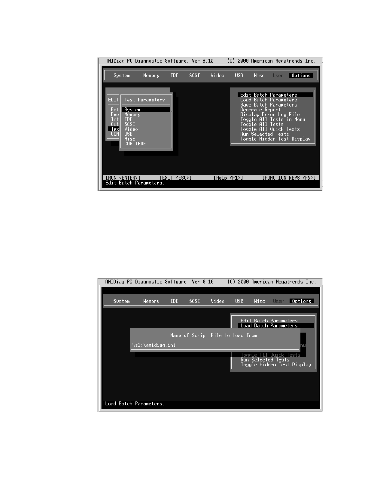
If
68
Test Parameters:
The Test Parameters menu is displayed when you select Edit
Batch Parameters from the Options menu.
Each item in this menu is the name of an AMIDiag menu. When you select an
AMIDiag menu choice, all AMIDiag tests on the menu are listed. Select the tests to
run in batch mode, and press Enter.
you select a test, the parameters for that test are displayed. Set the parameters,
and select another diagnostic test. Select CONTINUE, and press Enter when you
have set all test parameters for the AMIDiag test to be run in batch mode.
Load Batch Parameters
Choose this option to load previously saved AMIDiag batch diagnostic test
parameters. The Load Batch Parameters dialogue box appears:
Press Enter to accept the default batch parameter file (Diagnostic Utility.INI), or type
the appropriate AMIDiag batch parameter filename. You can use any valid filename.
IBM xSeries 450 Type 8688: Hardware Maintenance Manual and Troubleshooting Guide
Page 79

1.
2.
3.
To
1.
2.
The filename extension does not have to be .INI. You can then press F10 to run the
AMIDiag tests that are specified in this file.
Save Batch Parameters
Select this choice to save all batch mode parameters, selected tests, selected
devices, and error logging information to an AMIDiag batch parameter file. You can
then load this ASCII file later and use the same saved options and test parameters
every time you perform a AMIDiag session. To save batch parameters, complete the
following steps:
From the AMIDiag main menu, select Options, and press Enter.
Select Save Batch Parameters, and press Enter. The following appears:
Press Enter to accept the default batch parameter file (Diagnostic Utility.INI), or
type the appropriate AMIDiag batch parameter filename.
Generate Report
generate a report of the diagnostic test and all errors found, complete the
following steps:
From the main menu, select Options, and press Enter.
Select Generate Report to specify the output device: disk file or serial port.
Note: If a file is selected as an output device, you must ensure that a writeable
file system is available to write the report to from EFI.
Chapter 3. Diagnostics
69
Page 80

3.
1.
2. Go to
3.
70
The report generation parameters are as follows:
Select CONTINUE after setting report parameters, and press Enter.
can customize how the errors are logged and where the logs are saved using
You
the choices in this menu. You can define the destination for the output, log which
tests are conducted, when the test is started, when the test completes, and whether
the test will log only errors.
Toggle All Tests in Menu
Select this choice to display the list of test menus and to select a menu. When you
select a menu, the tests for that menu display. Select Toggle all tests to select all
tests. Select Toggle all quick tests to select all quick tests. Quick tests are
abbreviated versions of the complete test.
Run Selected Tests
Select this choice to run the tests that you have selected.
Toggle Hidden Test Display
Select this choice to display all hidden tests.
Ethernet diagnostic tests
Ethernet diagnostic programs are stored on the Resource CD. To use this CD,
complete the following steps:
Insert the CD into the DVD/CD-ROM drive, and restart the server.
the EFI shell; then, change to the file system on the CD, and navigate to
the x450 subdirectory on the CD.
Type enet_diag.nsh, and press Enter to run the program from the CD.
See the documentation on the Resource CD for more information about Ethernet
diagnostic tests and error codes.
Diagnostic error code tables
For descriptions of the error codes that might appear when you run the AMIDiag
program, see “Diagnostic error codes” on page 159.
IBM xSeries 450 Type 8688: Hardware Maintenance Manual and Troubleshooting Guide
Page 81

1.
2. If
If
If
To
1.
2.
3.
4.
5.
Notes:
Depending on your server configuration, some of the error codes might not
appear when you run the diagnostic programs.
diagnostic error codes appear that are not listed in the tables, make sure that
your server has the latest levels of SAL/EFI code, Remote Supervisor Adapter,
and diagnostics microcode installed.
Small computer system interface (SCSI) messages
you receive a SCSI error message, see “SCSI error messages” on page 184.
Note: If your server does not have a hard disk drive, ignore any message that
indicates that the SAL/EFI is not installed.
Recovering SAL/EFI code
the SAL/EFI code has become damaged, such as from a power failure during a
flash update, you can recover the SAL/EFI code using the SAL/EFI code page
jumper (J28 on the I/O board) and the recovery program on the Resource CD that
comes with the xSeries 450 server.
You can download the latest version of the SAL/EFI flash utility program from the
World Wide Web. Go to http;//www.ibm.com/eserver/xseries/, click IBM Server
Support, and make the selections for the server.
perform a full recovery of the SAL/EFI code, complete the following steps:
Review the safety information beginning on page 197.
Attention:
When you handle static-sensitive devices, take precautions to
avoid damage from static electricity. For details about handling these devices,
see “Handling static-sensitive devices” on page 78.
Note: You will not see anything displayed on the monitor when you perform
this procedure.
Insert the Resource CD into the DVD/CD-RW drive.
Turn off the server and peripheral devices, and disconnect all external cables
and power cords; then, open the cover (see “Opening the cover” on page 88).
Remove fans 3 and 4. For instructions, see “Replacing fan 3 or 4” on page
108.
Locate the SAL/EFI code page jumper (J28) on the I/O board.
3
12
Jumper (J28)
Chapter 3. Diagnostics
71
Page 82

If
to
7.
8.
9. If
to
or
1.
2.
3.
4.
5.
72
6.
there is a jumper on J28, move the jumper from pins 1 and 2 to pins 2 and 3
enable the SAL/EFI backup code page. If there is no jumper, add one to J28
pins 2 and 3.
Replace fans 3 and 4, and reconnect all external cables and power cords;
then, turn on the peripheral devices.
Start up the server. After 5-10 seconds, the blue Attention LED on the Light
Path card blinks.
the green access LED on the DVD/CD-RW drive does not blink to indicate
that the recovery flash image is being read within 2 minutes, press the reset
button on the front of the server to retry the update. If the LED fails to blink
again, the SAL/EFI backup code page might be damaged, and you might need
replace the I/O board to correct the problem. Run the AMIDiag program to
test the I/O board; then, see “I/O board, riser card, and Remote Supervisor
Adapter” on page 130 for instructions.
10.
When the DVD/CD-RW LED stops blinking, wait at least 5 minutes for the
flash update to complete.
11.
Remove the Resource CD from the drive, and repeat steps 3 on page 71
through 5 on page 71. Then, continue with step 12.
12.
Move the jumper on J28 to pins 1 and 2 to return to normal startup mode.
13.
Replace the fans, and close the cover (see “Closing the cover” on page 111).
14.
Reconnect all external cables and power cords, and turn on the peripheral
devices.
15.
Turn on the server.
Note: You might need to update the system firmware to the current level. For
instructions, see “Updating the firmware” on page 39.
Clearing a power-on password
This section applies to lost or forgotten passwords. For more information about lost
forgotten passwords, see “Using the Configuration/Setup Utility program” on page
12.
Complete the following steps to clear the power-on password:
Review the safety information beginning on page 197.
Attention:
avoid damage from static electricity. For details about handling these devices,
see “Handling static-sensitive devices” on page 78.
Turn off the server and all attached devices.
Unplug the power cord, and disconnect all external cables.
Open the top cover (see “Opening the cover” on page 88).
Remove fans 3 and 4. For instructions, see “Replacing fan 3 or 4” on page
108.
When you handle static-sensitive devices, take precautions to
IBM xSeries 450 Type 8688: Hardware Maintenance Manual and Troubleshooting Guide
Page 83

7.
8.
9.
1.
2.
3.
4.
5.
6.
Locate the clear password jumper (J20) on the I/O board. The following
illustration shows the location of the jumper on the I/O board.
3
12
Clear password
jumper (J20)
Move the clear password jumper from pins 1 and 2 to pins 2 and 3.
Replace fans 3 and 4, and reconnect all external cables and power cords;
then, turn on the peripheral devices.
Turn on the server. The EFI Boot Manager program starts.
10.
Follow the instructions to create a new password.
11.
Repeat steps 1 on page 72 through 5 on page 72.
12.
Return the clear password jumper to pins 1 and 2.
Clearing CMOS
Note: The password will be cleared on every startup until the jumper is
replaced to pins 1 and 2.
13.
Repeat steps 8 through 10.
14.
Close the cover (see “Closing the cover” on page 111).
15.
Connect the server to a power source, keyboard, monitor, and mouse.
16.
Turn on the server.
Complete the following steps to set the CMOS recovery jumper:
Review the safety information beginning on page 197.
Attention:
When you handle static-sensitive devices, take precautions to
avoid damage from static electricity. For details about handling these devices,
see “Handling static-sensitive devices” on page 78.
Turn off the server and all attached devices.
Unplug the power cord, and disconnect all external cables.
Open the top cover (see “Opening the cover” on page 88).
Remove fans 3 and 4. For instructions, see “Replacing fan 3 or 4” on page
108.
Chapter 3. Diagnostics
73
Page 84

7.
8.
9.
1.
2.
3.
on
4.
To
74
6.
Locate the CMOS recovery jumper (J19) on the I/O board. The following
illustration shows the location of the jumper on the I/O board.
3
12
CMOS recovery
jumper (J19)
Move the CMOS recovery jumper from pins 1 and 2 to pins 2 and 3.
Wait 60 seconds; then, return the CMOS recovery jumper to pins 1 and 2.
Replace fans 3 and 4.
10.
Close the cover (see “Closing the cover” on page 111).
11.
Connect the server to a power source, keyboard, monitor, and mouse.
12.
Turn on the server. The EFI Boot Manager program starts.
13.
Follow the instructions to erase the existing password or create a new
password.
14.
Select Save Settings, and press Enter.
Power checkout
Power problems can be difficult to solve. For example, a short circuit can exist
anywhere on any of the power distribution buses. Usually a short circuit will cause
the power subsystem to shut down because of an overcurrent condition.
Follow this general procedure for troubleshooting power problems:
Turn off the server, and disconnect all ac power cords.
Check for loose cables in the power subsystem. Also check for short circuits; for
example, a loose screw might be causing a short circuit on a circuit board.
Remove adapters and disconnect the cables and power connectors to all
internal and external devices until the server is at the minimum configuration
required to start the server (see the note about minimum operating requirements
page 180).
Reconnect all ac power cords, and turn on the server. If the server starts
successfully, replace adapters and devices one at a time until the problem is
isolated. If the server does not start up from the minimal configuration, replace
FRUs of the minimal configuration one at a time until the problem is isolated.
use this method, it is important to know the minimum configuration required for a
system to start (see the minimum configuration requirements at “Undetermined
problems” on page 185).
IBM xSeries 450 Type 8688: Hardware Maintenance Manual and Troubleshooting Guide
Page 85

If a
If
v
If
v
v
–
–
a
v
v
v
Troubleshooting the Ethernet controller
problem occurs with the 10/100/1000 Mbps Ethernet controller, use the Ethernet
diagnostic program on the Resource CD to diagnose the problem. For more
information about this CD, see “Ethernet diagnostic tests” on page 70. For
information about the Ethernet error codes and actions to take, see the
documentation on the Resource CD.
Network connection problems
the Ethernet controller cannot connect to the network, check the following
conditions:
Make sure that the cable is installed correctly.
The network cable must be securely attached at all connections. If the cable is
attached but the problem remains, try a different cable.
you set the Ethernet controller to operate at either 100 Mbps or 1000 Mbps,
you must use Category 5 or higher cabling.
Determine whether the hub supports auto-negotiation. If it does not, try
configuring the integrated Ethernet controller manually to match the speed and
duplex mode of the hub.
Check the Ethernet controller LEDs on the rear of the server.
These LEDs indicate whether a problem exists with the connector, cable, or hub.
The Ethernet transmit/receive activity LED on the rear of the server is lit when
the Ethernet controller sends or receives data over the Ethernet network. If
the Ethernet transmit/receive activity LED is off, make sure that the hub and
network are operating and that the correct device drivers are installed.
The Ethernet link status LED on the rear of the server is lit when the Ethernet
controller receives a LINK pulse from the hub. If the LED is off, there might be
defective connector or cable or a problem with the hub.
Make sure that you are using the correct device drivers, which are supplied with
v
your server.
Check for operating-system-specific causes for the problem.
Make sure that the device drivers on the client and server are using the same
protocol.
Test the Ethernet controller.
The way the Ethernet controller is tested depends on which operating system
you are using (see the Ethernet controller device driver README files).
Chapter 3. Diagnostics
75
Page 86

v
v
v
v
v
v If
v If
v
v
v
v
v
76
Ethernet controller troubleshooting chart
Use the following troubleshooting chart to find solutions to 10/100/1000 Mbps
Ethernet controller problems that have definite symptoms.
Ethernet controller problems
The server stops running when
loading device drivers.
FRU/actions
Check the following:
Make sure that you are using the most recent device driver available from the
World Wide Web.
Reseat or replace the adapter.
Ethernet link status LED does not
work.
Check the following:
Make sure that the hub is turned on.
Check all connections at the Ethernet controller and at the hub.
Use another port on the hub.
the hub does not support auto-negotiation, manually configure the Ethernet
controller to match the hub.
you manually configured the Duplex mode, make sure that you also
manually configure the speed.
Reseat or replace the adapter.
The Ethernet transmit/receive
activity LED does not work.
Check the following:
Make sure that you have loaded the network device drivers.
The network might be idle. Try sending data from this server.
Data is incorrect or sporadic.
Check the following:
Make sure that you are using Category 5 or higher cabling when operating the
server at 100 Mbps or at 1000 Mbps.
Make sure that the cables do not run close to noise-inducing sources like
fluorescent lights.
Ethernet controller messages
The integrated Ethernet controller might display messages from certain device
drivers. The latest information available concerning these messages will be made
available at the IBM Support Web site at http://www.ibm.com/eserver/xseries.
IBM xSeries 450 Type 8688: Hardware Maintenance Manual and Troubleshooting Guide
Page 87

v
v
v
v
To
v
v
v
v
v
v A
v
v Do
v
v
v Do
v
v
©
Chapter 4. Installing options
This chapter provides detailed instructions for installing hardware options in your
server.
Installation guidelines
Before you begin to install options in your server, read the following information:
Read the safety information beginning on page 197 and the guidelines in
“Handling static-sensitive devices” on page 78. This information will help you
work safely with your server or options.
Make sure that you have an adequate number of properly grounded electrical
outlets for your server, monitor, and any other devices that you will connect to the
server.
Back up all important data before you make changes to disk drives.
For a list of supported options for your server, go to
http://www.ibm.com/pc/us/compat/.
Note:
Some preconfigured servers have a unique list of supported options. See the
software documentation provided with those servers for more information.
System reliability considerations
help ensure proper cooling and system reliability, make sure that:
Each of the drive bays has either a drive or a filler panel installed.
There is space around the server to allow the cooling system to work properly.
Cables for optional adapters are routed according to the instructions that are
provided with the adapters.
All microprocessors have the same cache size and type and the same clock
speed.
For proper cooling, do not leave the cover open for more than 15 minutes.
failed fan is replaced within 48 hours.
The top cover is closed during normal operation.
not remove a defective power supply until a replacement is available.
For redundant and hot-swappable operation, the power supplies are connected to
200-240 V ac.
Working inside a server with power on
Your server supports hot-swap devices and is designed to operate safely while
turned on with the cover removed. Follow these guidelines when you work inside a
server that is turned on:
Avoid loose-fitting clothing on your forearms. Button long-sleeved shirts before
working inside the server; do not wear cuff links while you are working inside the
server.
not allow your necktie or scarf to hang inside the server.
Remove jewelry, such as bracelets, rings, necklaces, and loose-fitting wrist
watches.
Remove items from your shirt pocket (such as pens or pencils) that could fall into
the server as you lean over it.
Copyright IBM Corp. 2003
77
Page 88

or
To
v
v
v Do
v Do
v
v
in to
v
v
is
78
v
Take care to avoid dropping any metallic objects, such as paper clips, hair pins,
screws, into the server.
Handling static-sensitive devices
Attention: Static electricity can damage electronic devices and your system. To
avoid damage, keep static-sensitive devices in their static-protective package until
you are ready to install them.
reduce the possibility of electrostatic discharge, observe the following
precautions:
Limit your movement. Movement can cause static electricity to build up around
you.
Handle the device carefully, holding it by its edges or its frame.
not touch solder joints, pins, or exposed printed circuitry.
not leave the device where others can handle and damage it.
While the device is still in its anti-static package, touch it to an unpainted metal
part of the system unit for at least 2 seconds. This drains static electricity from
the package and from your body.
Remove the device from its package, and install it directly into the system unit
without setting down the device. If it is necessary to set down the device, place it
its static-protective package. Do not place the device on your system unit
cover or on a metal surface.
Take additional care when handling devices during cold weather. Heating reduces
indoor humidity and increases static electricity.
Wear a properly grounded wrist strap against your skin to help eliminate static
electricity from your body.
Major components of the xSeries 450 server
The orange color on components and labels in the server indicates hot-swap or
hot-plug components. You can install or remove these components while the server
running, provided that the server is configured to support hot-swap and hot-plug
components.
The blue color on components and labels indicates touch points, where a
component can be gripped, a latch moved, and so on.
IBM xSeries 450 Type 8688: Hardware Maintenance Manual and Troubleshooting Guide
Page 89

The following illustration shows the locations of major components in your server.
DIMM
access
DIMM
doors
Fan 1
N
O
T
E
:
F
O
R
P
F
R
O
N
T
O
Fan 2
N
O
T
E
F
R
O
P
E
R
A
IR
F
L
O
W, R
E
P
L
A
C
E
F
B
O
X
Fan 3
:
F
O
R
P
R
O
P
E
R
A
I
R
F
L
O
W,
R
E
R
O
N
T
O
F
B
O
X
F
A
N
W
I
T
H
IN
2
M
I
N
U
T
E
S
Fan 4
P
L
A
C
E
F
A
N
W
IT
H
I
N
2
M
I
N
U
T
Microprocessor
Microprocessor
baffle
Power
module
VRM
E
S
Retention
bracket
Hot-swap
power supply
Hard disk
drive
DVD-ROM
drive
Bezel
Chapter 4. Installing options
79
Page 90

80
Connector and LED locations
The illustrations in this section show the locations of connectors, switch and jumper
blocks, and LEDs.
Memory board internal connectors and LEDs
The following illustrations show the internal connectors and LEDs on the memory
board.
DIMM slots
DIMM error LED
(14 places)
VRM connectors
2.5 V VRM error LED
2.5 V VRM port 1
error LED
1.8 V VRM
error LED
DIMM error LED
(14 places)
2.5 V VRM port 2
error LED
IBM xSeries 450 Type 8688: Hardware Maintenance Manual and Troubleshooting Guide
Page 91

N
O
T
E
:
F
O
R
P
R
O
P
E
R
A
IR
F
L
O
W, R
E
P
L
A
C
E
F
A
N
W
IT
H
IN
2 M
IN
U
T
E
S
F
R
O
N
T
O
F
B
O
X
N
O
T
E
:
F
O
R
P
R
O
P
ER
AIR
F
L
O
W, R
E
P
LA
C
E
F
A
N
W
IT
H
IN
2
M
IN
U
T
E
S
F
R
O
N
T
O
F
B
O
X
The following illustration identifies the LEDs on the memory-board assembly.
Memory port 1 LED Memory port 2 LED
Memory switch card LEDs
The following illustration shows the LEDs on the memory switch card.
Memory port 1
power LED
Memory port 2
power LED
Chapter 4. Installing options
81
Page 92

82
Processor board internal connectors and LEDs
The following illustrations show the internal connectors on the processor board.
Front side
Microprocessor 3 socket
Microprocessor 1 socket
Light Path Diagnostic button
Microprocessor 3
power module socket
Microprocessor 3
power module
cable connector
Microprocessor 1
power module socket
Microprocessor 1
power module
cable connector
Reverse Side
Microprocessor 4 power
module socket
Microprocessor 4 power
module cable connector
Microprocessor 2 power
module socket
Microprocessor 2 power
module cable connector
Microprocessor 4 socket
Microprocessor 2 socket
IBM xSeries 450 Type 8688: Hardware Maintenance Manual and Troubleshooting Guide
Page 93
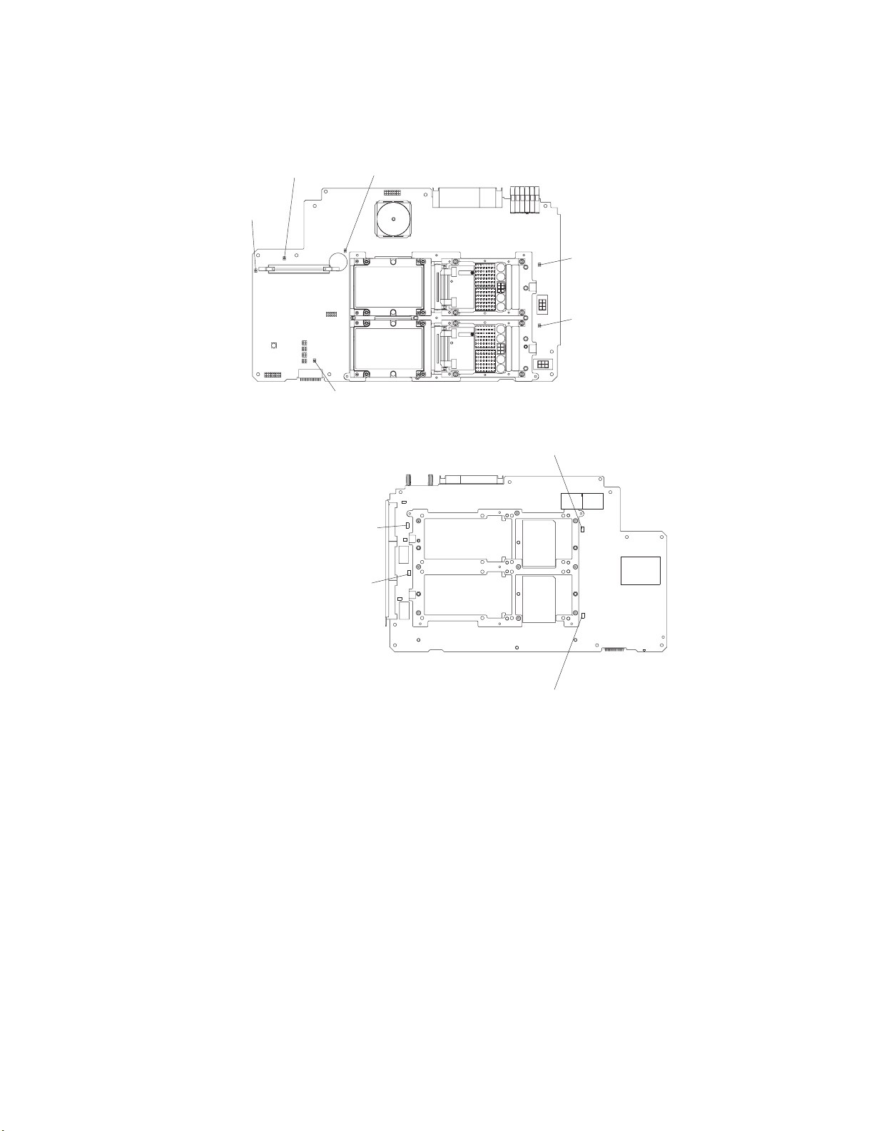
The following illustrations show the LEDs on the processor board.
Front side
Power-good
LED
VRM
error
LED
Microprocessor 3
error LED
Microprocessor 1
error LED
Microprocessor 3
power module
error LED
Microprocessor 1
power module
error LED
Reverse side
Microprocessor 4 power
module error LED
Microprocessor 2 power
module error LED
Microprocessor 4 error LED
Microprocessor 2 error LED
Chapter 4. Installing options
83
Page 94

84
Midplane board connectors and LEDs
The following illustration shows the connectors on the midplane board.
Force power-on
connector
3.3V VRM
connector
Force NMI switch
Light Path
card connector
Memory connector
Microprocessor
connector
Microprocessor
power
connector
Power backplane
signal connector
Midplane thumbscrews
SCSI backplane and
I2C connector
Power backplane
ground connector
Power backplane
12V connector
The following illustration shows the LEDs on the midplane board.
I/O board error LED
Remote Supervisor Adapter error LED
Machine check
abort initiated
(NMI) LED
VRM error
LED
Diagnostic
display
DMC heartbeat LED
PCI-X planer board error LED
Midplane board error LED
Processor board error LED
Memory board error LED
Midplane power good LED
IBM xSeries 450 Type 8688: Hardware Maintenance Manual and Troubleshooting Guide
Page 95

1
2
3
4
5
6
You can see the midplane board LEDs on the top of the server. These LEDs are
numbered from 1-6 and indicate the board on which an error has been detected.
6 I/O board error LED
5 Remote Supervisor
Adapter error LED
4 PCI-X board error LED
3 Midplane board error LED
2 Processor board Error LED
1 Memory board error LED
NOTE: FOR PROPER AIRFLOW, REPLACE FANWITHIN 2 MINUTES
NOTE: FOR PROPER AIRFLOW, REPLACE FANWITHIN 2 MINUTES
FRONT OF BOX
FRONT OF BOX
Table 7. Midplane board LEDs
LED number
Board
Memory-board error LED
Processor-board error LED
Midplane-board error LED
PCI-X board error LED
Remote Supervisor Adapter error LED
I/O-board error LED
Chapter 4. Installing options
85
Page 96

86
PCI-X board internal connectors and LEDs
The following illustration shows the internal connectors and LEDs on the PCI-X
board.
PCI-X slot 6
(133 MHz)
PCI-X slot 5
(133 )MHz
PCI-X slot 4
(100 )MHz
PCI-X slot 3
(100 )MHz
PCI-X slot 2
(66 )MHz
Attention LED
Power LED
PCI-X slot 1
(66 )MHz
IBM xSeries 450 Type 8688: Hardware Maintenance Manual and Troubleshooting Guide
Page 97

I/O-board internal connectors
The following illustration shows the internal connectors on the I/O board.
SCSI B
connector
I/O VRM
Fan 4
connector
Fan 3
connector
Power/reset
connector
SCSI A
connector
Riser card
connector
Fans 1 and 2
connectors
USB cable
connector
Media bays
connector
I/O-board jumpers
The following illustration identifies the jumpers on the I/O board.
Clear power-on
password
jumper (J20)
CMOS recovery
jumper (J19)
SAL/EFI code page
jumper (J28)
Chapter 4. Installing options
87
Page 98

1.
on
2.
3.
4.
88
Remote Supervisor Adapter connectors and LEDs
The following illustration identifies the connectors and LEDs on the Remote
Supervisor Adapter.
Ethernet activity
External power
supply connector
LED (green)
Error LED
(amber)
P
P
Ethernet link
LED (green)
Lithium
battery
Power LED
(green)
Opening the cover
Complete the following steps to open the server cover:
Serial
connector
(COM)
Ethernet
connector
(RJ-45)
ASM Interconnect port
(RJ-14)
Read the safety information beginning on page 197 and “Installation guidelines”
page 77.
Slide the server out from the rack.
Pull the release latch on the left side of the top cover to the right.
Using the finger hole in the release latch, open the left side of the cover; then,
open the right side of the cover.
Latch
N
O
T
E
:
F
O
R
P
R
O
P
E
R
A
IR
F
L
O
W, R
E
P
LA
C
E
F
A
F
N
R
W
O
R
P
R
O
P
E
R
A
T
O
F
B
O
X
ITH
N
T
O
IN
F
2
B
M
O
IN
X
IR
F
L
O
W, R
U
T
E
E
P
LA
S
C
E
F
A
N
W
IT
H
IN
2 M
IN
U
T
E
S
Attention:
N
O
T
E
:
F
O
F
R
O
N
For proper cooling and airflow, close the cover before turning on
the server. Operating the server for extended periods of time (over 15 minutes)
with the cover open might damage server components.
IBM xSeries 450 Type 8688: Hardware Maintenance Manual and Troubleshooting Guide
Page 99

1.
2.
1.
2.
Removing and replacing the bezel
Complete the following steps to remove the bezel:
Press on the two tabs at the top edge of the bezel, and pull the top of the bezel
slightly away from the server.
Press on the two tabs at the bottom edge of the bezel, and pull the bezel off the
server. Store the bezel in a safe place.
NOTE: FOR PROPE
FRONT OF BOX
R AIRFLO
C
o
m
m
o
n
W, REPLACE FANWITHIN
4
P
C
I B
o
a
r
5
S
y
s
t
6
I
/O
B
o
a
r
d
F
R
U
N
u
m
b
e
rs
NOT
E: FO
R PR
O
PER AIR
FLO
W, R
EPLA
C
E FANWITHIN 2 MINUTES
FRONT OF BO
X
2 MINUTES
d
e
m
M
a
n
a
g
e
m
e
n
t
B
o
a
r
d
M
id
p
l
a
n
e
B
o
a
r
L
i
g
h
t
-P
a
t
h
D
i
a
g
d
n
o
s
t
ic
s
U
p
p
e
r
C
E
C
L
o
w
e
r
C
E
C
1
2
3
Complete the following steps to replace the bezel:
Align the four tabs on the bezel with the slots in the server chassis.
Press firmly against the front of the bezel until it snaps into place.
4
P
C
I
B
o
a
r
d
t
e
m
M
a
n
a
g
e
m
e
n
t
B
o
a
r
d
L
o
w
e
r
C
E
C
M
i
d
p
la
n
e
B
o
a
r
d
L
ig
h
t
-P
a
t
h
D
i
a
g
n
o
s
t
ic
s
3
6
C
o
m
m
o
n
F
R
U
N
u
m
b
e
rs
NOTE: FOR PROPER AIRFLOW, REPLACE FANWITHIN 2 MINUTES
NOTE: FOR PROPER AIRFLOW, REPLACE FANWITHIN 2 MINUTES
FRONT OF BOX
FRONT OF BOX
5
S
y
s
I
/O
B
o
a
r
d
U
p
p
e
r
C
E
C
1
2
Chapter 4. Installing options
89
Page 100

of
1.
2.
3.
If
a
1.
on
2.
90
Removing and replacing a hot-swap power supply
Your server comes with two hot-swap power supplies, which you can remove and
replace without turning off the server. The following illustration shows the locations
the power supplies on the front of the server.
Power LEDs Power supply 1
Power supply 2
Power-on LED
Power button
Reset button
Power-supply
latch
Handle
Before you remove or replace a power supply, review the following information.
Notes:
The power supplies are hot-swappable and redundant only at 200-240 V ac.
Both power supplies must be connected to the power source for operation at
100-127 V ac.
During normal operation, both power supplies must be installed for proper
operation and cooling.
you install or remove a power supply, observe the following precautions.
Statement 8:
CAUTION:
Never remove the cover on a power supply or any part that has the following
label attached.
Hazardous voltage, current, and energy levels are present inside any
component that has this label attached. There are no serviceable parts inside
these components. If you suspect a problem with one of these parts, contact
service technician.
Complete the following steps to remove and replace a power supply:
Read the safety information beginning on page 197 and “Installation guidelines”
page 77.
Remove the front bezel (see “Removing and replacing the bezel” on page 89 for
instructions about removing the front bezel).
IBM xSeries 450 Type 8688: Hardware Maintenance Manual and Troubleshooting Guide
 Loading...