

Page 1

ERserver
Hardware Maintenance Manual
xSeries 360 Type 8686
Page 2

Page 3

ER s e r v e r
Hardware Maintenance Manual
xSeries 360 Type 8686
Page 4

©
US
Note:
Before using this information and the product it supports, be sure to read the general information under “Notices” on
page 178.
Eighth Edition August 2004
The following paragraph does not apply to the United Kingdom or any country where such provisions are
inconsistent with local law:
INTERNATIONAL BUSINESS MACHINES CORPORATION PROVIDES THIS PUBLICATION “AS IS” WITHOUT
WARRANTY OF ANY KIND, EITHER EXPRESS OR IMPLIED, INCLUDING, BUT NOT LIMITED TO, THE IMPLIED
WARRANTIES OF MERCHANTABILITY OR FITNESS FOR A PARTICULAR PURPOSE. Some states do not allow
disclaimer of express or implied warranties in certain transactions, therefore, this statement may not apply to you.
This publication could include technical inaccuracies or typographical errors. Changes are periodically made to the
information herein; these changes will be incorporated in new editions of the publication. IBM may make
improvements and/or changes in the product(s) and/or the program(s) described in this publication at any time.
This publication was developed for products and services offered in the United States of America. IBM may not offer
the products, services, or features discussed in this document in other countries, and the information is subject to
change without notice. Consult your local IBM representative for information on the products, services, and features
available in your area.
Requests for technical information about IBM products should be made to your IBM reseller or IBM marketing
representative.
Copyright International Business Machines Corporation 2003. All rights reserved.
Government Users Restricted Rights – Use, duplication or disclosure restricted by GSA ADP Schedule Contract
with IBM Corp.
Page 5

Be
©
About this manual
This manual contains diagnostic information, a Symptom-to-FRU index, service
information, error codes, error messages, and configuration information for the IBM
Eserver xSeries
®
Important: This manual is intended for trained servicers who are familiar with IBM
xSeries products.
Important safety information
sure to read all caution and danger statements in this book before performing
any of the instructions.
Leia todas as instruções de cuidado e perigo antes de executar qualquer operação.
Prenez connaissance de toutes les consignes de type Attention et
Danger avant de procéder aux opérations décrites par les instructions.
Lesen Sie alle Sicherheitshinweise, bevor Sie eine Anweisung ausführen.
®
360, Type 8686.
Online support
Accertarsi di leggere tutti gli avvisi di attenzione e di pericolo prima di effettuare
qualsiasi operazione.
Lea atentamente todas las declaraciones de precaución y peligro ante de llevar a
cabo cualquier operación.
WARNING: Handling the cord on this product or cords associated with accessories
sold with this product, will expose you to lead, a chemical known to the State of
California to cause cancer, and birth defects or other reproductive harm. Wash
hands after handling.
ADVERTENCIA: El contacto con el cable de este producto o con cables de
accesorios que se venden junto con este producto, pueden exponerle al plomo, un
elemento químico que en el estado de California de los Estados Unidos está
considerado como un causante de cancer y de defectos congénitos, además de
otros riesgos reproductivos. Lávese las manos después de usar el producto.
You can download the most current diagnostic, BIOS flash, and device driver files
from http://www.ibm.com/pc/support on the World Wide Web.
Copyright IBM Corp. 2003
iii
Page 6

iv
Hardware Maintenance Manual: xSeries 360 Type 8686
Page 7

©
Contents
About this manual . . . . . . . . . . . . . . . . . . . . . . . iii
Important safety information . . . . . . . . . . . . . . . . . . . . iii
Online support . . . . . . . . . . . . . . . . . . . . . . . . . iii
General checkout . . . . . . . . . . . . . . . . . . . . . . . .1
Features overview . . . . . . . . . . . . . . . . . . . . . . . .3
Features and specifications . . . . . . . . . . . . . . . . . . . . .4
Notices and statements used in this book . . . . . . . . . . . . . . .4
What the xSeries 360 offers . . . . . . . . . . . . . . . . . . . .5
Reliability, availability, and serviceability . . . . . . . . . . . . . . . .7
Controls and indicators . . . . . . . . . . . . . . . . . . . . . .8
Operator information panel . . . . . . . . . . . . . . . . . . . . .9
Turning on the server . . . . . . . . . . . . . . . . . . . . .10
Turning off the server . . . . . . . . . . . . . . . . . . . . .11
Standby mode . . . . . . . . . . . . . . . . . . . . . . . .12
Diagnostics . . . . . . . . . . . . . . . . . . . . . . . . . .13
Diagnostic tools overview . . . . . . . . . . . . . . . . . . . . .13
POST . . . . . . . . . . . . . . . . . . . . . . . . . . . .14
Error logs . . . . . . . . . . . . . . . . . . . . . . . . . . .14
Small computer systems interface (SCSI) messages . . . . . . . . . . .14
Diagnostic programs and error messages . . . . . . . . . . . . . . .15
Starting the diagnostic programs . . . . . . . . . . . . . . . . .15
Error code format . . . . . . . . . . . . . . . . . . . . . . .16
Text message format . . . . . . . . . . . . . . . . . . . . . .16
Viewing the test log . . . . . . . . . . . . . . . . . . . . . .17
Viewing the System Event/Error log . . . . . . . . . . . . . . . .17
Diagnostic error messages . . . . . . . . . . . . . . . . . . .17
Recovering the BIOS code . . . . . . . . . . . . . . . . . . . .18
Power supply LEDs . . . . . . . . . . . . . . . . . . . . . . .19
Level 2 Light Path Diagnostics . . . . . . . . . . . . . . . . . . .19
Level 2 diagnostic panel LEDs . . . . . . . . . . . . . . . . . .20
Level 2 Light Path troubleshooting . . . . . . . . . . . . . . . . .21
Power checkout . . . . . . . . . . . . . . . . . . . . . . . .22
Error symptoms . . . . . . . . . . . . . . . . . . . . . . . .22
Ethernet controller troubleshooting . . . . . . . . . . . . . . . . . .22
Battery replacement . . . . . . . . . . . . . . . . . . . . . . .23
Configuration . . . . . . . . . . . . . . . . . . . . . . . . .27
Using the Configuration/Setup Utility . . . . . . . . . . . . . . . . .28
Starting the Configuration/Setup Utility . . . . . . . . . . . . . . .28
Configuration/Setup Utility main menu . . . . . . . . . . . . . . .28
Using passwords . . . . . . . . . . . . . . . . . . . . . . . .32
Power-on password . . . . . . . . . . . . . . . . . . . . . .32
Administrator password . . . . . . . . . . . . . . . . . . . . .33
Remote-control security settings . . . . . . . . . . . . . . . . .34
Using the SCSISelect utility program . . . . . . . . . . . . . . . . .34
Starting the SCSISelect utility program . . . . . . . . . . . . . . .34
SCSISelect menu . . . . . . . . . . . . . . . . . . . . . . .35
PXE Boot Agent Utility program . . . . . . . . . . . . . . . . . . .36
Starting the PXE Boot Agent Utility program . . . . . . . . . . . . .36
PXE Boot Agent Utility menu . . . . . . . . . . . . . . . . . . .36
Copyright IBM Corp. 2003
v
Page 8

vi
ServeRAID configuration program . . . . . . . . . . . . . . . . . .37
Configuring the Ethernet controller . . . . . . . . . . . . . . . . . .37
Remote Supervisor Adapter . . . . . . . . . . . . . . . . . . . .38
Remote Supervisor Adapter features . . . . . . . . . . . . . . . .38
Setup requirements . . . . . . . . . . . . . . . . . . . . . .38
Using the documentation . . . . . . . . . . . . . . . . . . . .39
Cabling and configuring the Remote Supervisor Adapter . . . . . . . . .39
Configuring the adapter . . . . . . . . . . . . . . . . . . . . .41
Using the ASM interconnect network . . . . . . . . . . . . . . . .50
Using the ServerGuide CDs . . . . . . . . . . . . . . . . . . .57
Features at a glance . . . . . . . . . . . . . . . . . . . . . . .58
Setup and configuration overview . . . . . . . . . . . . . . . . . .58
System partition . . . . . . . . . . . . . . . . . . . . . . . .60
Typical NOS Installation . . . . . . . . . . . . . . . . . . . . .60
Setting up or updating multiple servers . . . . . . . . . . . . . . . .60
Installing the NOS without ServerGuide . . . . . . . . . . . . . . . .61
Additional programs included with ServerGuide . . . . . . . . . . . . .61
Installing components . . . . . . . . . . . . . . . . . . . . .63
Major components of the xSeries 360 server . . . . . . . . . . . . . .64
Internal connector and LED locations . . . . . . . . . . . . . . . . .65
System board locations . . . . . . . . . . . . . . . . . . . . .65
Level 2 diagnostic and system board LEDs . . . . . . . . . . . . .68
Memory board locations . . . . . . . . . . . . . . . . . . . .70
Remote Supervisor Adapter locations . . . . . . . . . . . . . . .71
Before you begin . . . . . . . . . . . . . . . . . . . . . . . .71
System reliability considerations . . . . . . . . . . . . . . . . .71
Working inside the server with the power on . . . . . . . . . . . . .72
Internal component locations . . . . . . . . . . . . . . . . . . . .72
Removing the server top cover and bezel . . . . . . . . . . . . . .72
Working with adapters . . . . . . . . . . . . . . . . . . . . .73
Internal drive installation . . . . . . . . . . . . . . . . . . . .79
Memory modules . . . . . . . . . . . . . . . . . . . . . . .84
Microprocessor installation . . . . . . . . . . . . . . . . . . .86
VRM replacement . . . . . . . . . . . . . . . . . . . . . . .89
Hot-swap power supply installation . . . . . . . . . . . . . . . .90
Hot-swap fan replacement . . . . . . . . . . . . . . . . . . . .92
Installing the serial cable . . . . . . . . . . . . . . . . . . . .93
Locking PCI slot 6 . . . . . . . . . . . . . . . . . . . . . . .94
Enabling the serial port . . . . . . . . . . . . . . . . . . . . .95
Completing the installation . . . . . . . . . . . . . . . . . . . .95
Connecting external options . . . . . . . . . . . . . . . . . . . .97
Input/output ports . . . . . . . . . . . . . . . . . . . . . . .97
Cabling the server . . . . . . . . . . . . . . . . . . . . . . 103
FRU information (service only) . . . . . . . . . . . . . . . . . . 105
Hot-swap drive backplane . . . . . . . . . . . . . . . . . . . . 105
Light path diagnostic card . . . . . . . . . . . . . . . . . . . . 106
Operator panel card . . . . . . . . . . . . . . . . . . . . . . 108
PCI adapter switch card . . . . . . . . . . . . . . . . . . . . . 109
Power supply backplane . . . . . . . . . . . . . . . . . . . . .110
System board/shuttle . . . . . . . . . . . . . . . . . . . . . .110
Replacing the serial port cable . . . . . . . . . . . . . . . . . . .113
Symptom-to-FRU index . . . . . . . . . . . . . . . . . . . . .115
Hardware Maintenance Manual: xSeries 360 Type 8686
Page 9

No
Beep symptoms . . . . . . . . . . . . . . . . . . . . . . . .115
beep symptoms . . . . . . . . . . . . . . . . . . . . . . .117
Level 2 light path LED errors . . . . . . . . . . . . . . . . . . .118
Diagnostic error codes . . . . . . . . . . . . . . . . . . . . . 120
Error symptoms . . . . . . . . . . . . . . . . . . . . . . . . 127
ServerGuide error symptoms . . . . . . . . . . . . . . . . . . . 131
SMI Handler messages . . . . . . . . . . . . . . . . . . . . . 132
Power supply LED errors . . . . . . . . . . . . . . . . . . . . . 133
POST error codes . . . . . . . . . . . . . . . . . . . . . . . 134
ServeRAID . . . . . . . . . . . . . . . . . . . . . . . . . . 139
SCSI error codes . . . . . . . . . . . . . . . . . . . . . . . 139
Temperature error messages . . . . . . . . . . . . . . . . . . . 139
Fan error messages . . . . . . . . . . . . . . . . . . . . . . 140
Power error messages . . . . . . . . . . . . . . . . . . . . . 140
System shutdown . . . . . . . . . . . . . . . . . . . . . . . 141
Voltage related system shutdown . . . . . . . . . . . . . . . . . 141
Temperature related system shutdown . . . . . . . . . . . . . . . 141
DASD checkout . . . . . . . . . . . . . . . . . . . . . . . . 141
Processor checkout . . . . . . . . . . . . . . . . . . . . . . . 142
I2C bus fault messages . . . . . . . . . . . . . . . . . . . . . 142
Undetermined problems . . . . . . . . . . . . . . . . . . . . . 143
Related service information . . . . . . . . . . . . . . . . . . . 145
Safety information . . . . . . . . . . . . . . . . . . . . . . . 145
General safety . . . . . . . . . . . . . . . . . . . . . . . 145
Electrical safety . . . . . . . . . . . . . . . . . . . . . . . 146
Safety inspection guide . . . . . . . . . . . . . . . . . . . . 147
Handling static-sensitive devices . . . . . . . . . . . . . . . . . 148
Grounding requirements . . . . . . . . . . . . . . . . . . . . 148
Safety notices (multilingual translations) . . . . . . . . . . . . . . 149
Problem determination tips . . . . . . . . . . . . . . . . . . . . 178
Notices . . . . . . . . . . . . . . . . . . . . . . . . . . . 178
Trademarks . . . . . . . . . . . . . . . . . . . . . . . . . . 179
Parts . . . . . . . . . . . . . . . . . . . . . . . . . . . . 181
System . . . . . . . . . . . . . . . . . . . . . . . . . . . 183
Keyboards . . . . . . . . . . . . . . . . . . . . . . . . . . 184
Contents
vii
Page 10

viii
Hardware Maintenance Manual: xSeries 360 Type 8686
Page 11

on
If
A
A
v
v
v
If
in
1.
2. If
3. If
on
4. If
5.
on
6.
7.
©
General checkout
The server diagnostic programs are stored in upgradable read-only memory (ROM)
the system board. These programs are the primary method of testing the major
components of a server. Major components that can be tested include the system
board, Ethernet controller, video controller, RAM, keyboard, mouse (pointing
device), diskette drive, serial ports, hard drives, and parallel port. Not all servers
include all of these items; your hardware might differ. You can also use the
diagnostic programs to test some external devices. See “Diagnostic programs and
error messages” on page 15.
you cannot determine whether a problem is caused by the hardware or by the
software, you can run the diagnostic programs to confirm that the hardware is
working properly.
When you run the diagnostic programs, a single problem might cause several error
messages. When this occurs, work to correct the cause of the first error message.
After the cause of the first error message is corrected, the other error messages
might not occur the next time you run the test.
failed server might be part of a shared DASD cluster (two or more servers
sharing the same external storage device(s)). Prior to running diagnostics, verify
that the failing server is not part of a shared DASD cluster.
server might be part of a cluster if:
The customer identifies the server as part of a cluster.
One or more external storage units are attached to the server and at least one of
the attached storage units is additionally attached to another server or
unidentifiable source.
One or more servers are located near the failing server.
the failing server is suspected to be part of a shared DASD cluster, all diagnostic
tests can be run except diagnostic tests which test the storage unit (DASD residing
the storage unit) or the storage adapter attached to the storage unit.
Notes:
For servers that are part of a shared DASD cluster, run one test at a time in
looped mode. Do not run all tests in looped mode, as this could enable the
DASD diagnostic tests.
multiple error codes are displayed, diagnose the first error code displayed.
the server stops working with a POST error, go to “Symptom-to-FRU index”
page 115.
the server stops working and no error is displayed, go to “Undetermined
problems” on page 143.
For information about power supply problems, see “Power supply LED errors”
page 133.
For safety information, see “Safety information” on page 145.
For intermittent problems, check the error log; see “Error logs” on page 14.
Copyright IBM Corp. 2003
1
Page 12

v
v
v
v
v
v
v
v
v
v
1.
2.
If
If
2
001 IS THE SERVER PART OF A CLUSTER?
YES. Schedule maintenance with the customer. Shut down all servers
related to the cluster. Run storage test.
NO. Go to step 002.
002 IF THE SERVER IS NOT PART OF A CLUSTER:
Turn off the server and all external devices.
Check all cables and power cords.
Set all display controls to the middle position.
Turn on all external devices.
Turn on the server.
Record any POST error messages displayed on the screen. If an error is
displayed, look up the first error in the “POST error codes” on page 134.
Check the diagnostic LED panel system error LED; if on, see “Level 2
Light Path Diagnostics” on page 19.
Check the System Error Log. If the server recorded an error, see
“Symptom-to-FRU index” on page 115.
Start the diagnostic programs. See “Diagnostic programs and error
messages” on page 15.
Check for the following responses:
One beep.
Readable instructions or the Main Menu.
003
DID YOU RECEIVE BOTH OF THE CORRECT RESPONSES?
NO. Find the failure symptom in “Symptom-to-FRU index” on page 115.
YES. Run the diagnostic programs. If necessary, see “Diagnostic programs
and error messages” on page 15.
you receive an error, go to “Symptom-to-FRU index” on page 115.
the diagnostics completed successfully and you still suspect a problem,
see “Undetermined problems” on page 143.
Hardware Maintenance Manual: xSeries 360 Type 8686
Page 13
If
©
Features overview
The IBM Eserver xSeries 360 server, which features IBM X-Architecture
technology, is a high-performance rack model server that can be upgraded to a
symmetric multiprocessing (SMP) server. It is ideally suited for networking
environments that require superior microprocessor performance, efficient memory
management, flexibility, and large amounts of reliable data storage.
Performance, ease of use, reliability, and expansion capabilities are key features of
the server. These design features make it possible for you to customize the
hardware to meet your needs today, while providing flexible expansion capabilities
for the future.
you have access to the World Wide Web, you can obtain up-to-date information
about the server model and other IBM server products at
http://www.ibm.com/eserver/xseries/.
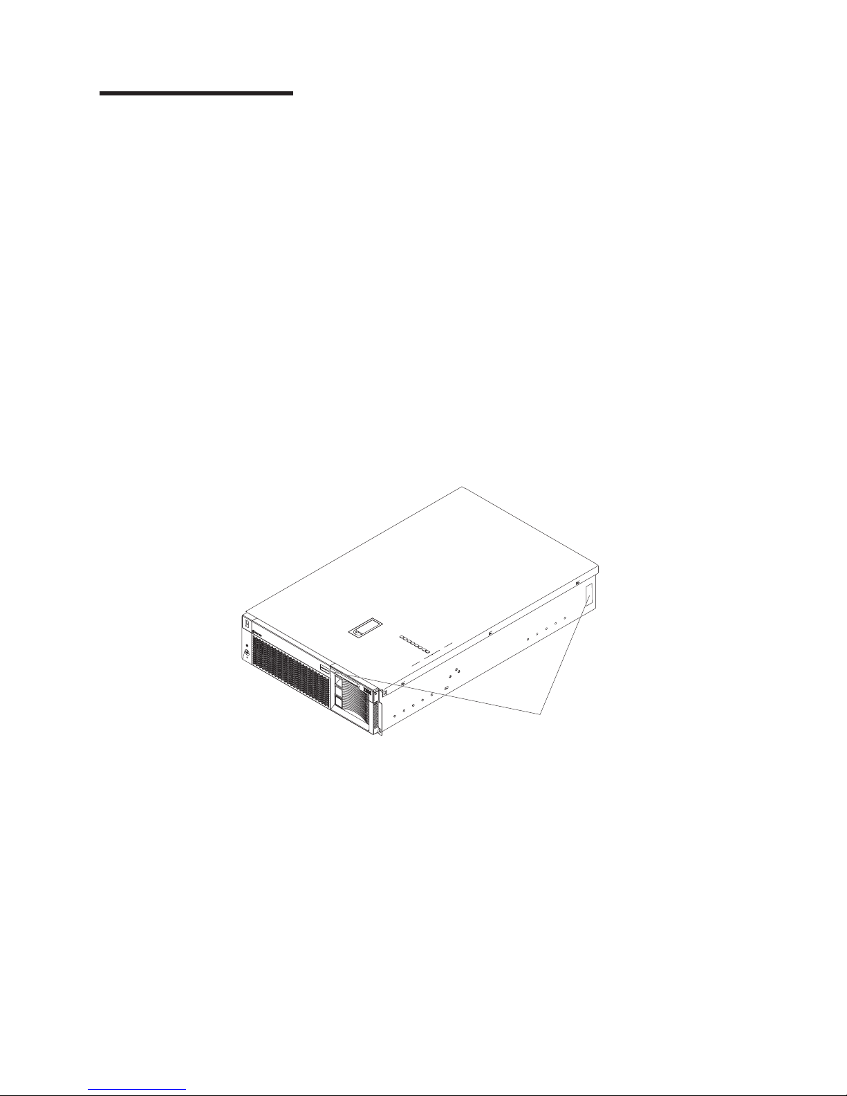
The machine type, model number, and serial number are on the ID labels, one
located on the bezel to the left of the CD-ROM drive and the other at the rear of the
right side, as shown in the following illustration.
Note: The illustrations in this document might differ slightly from your hardware.
ID labels
Copyright IBM Corp. 2003
3
Page 14

v
–
–
v
v
–
–
v
v
v
v
v
v
v
v
v S3
v
v 8 MB
(3 U) v
v
v
v
v
v
v
v
–
–
–
–
–
v
v
v
v
v
v
v
v
–
–
–
–
–
v
v
v
v
–
–
–
–
–
–
–
in
v
v
4
Features and specifications
The following table provides a summary of the features and specifications for the
xSeries 360 server.
Table 1. Features and Specifications
Microprocessor:
®
Intel
™
Xeon
Processor MP (frequency
varies with server model; each MP
processor functions as two logical
processors)
Minimum: two
Maximum: four
v
Level-3 cache size varies with model
100 MHz front-side bus (FSB)
Chipset:
IBM XA-32
™
Chipset with integrated
memory, I/O controller, and remote I/O
controller. Memory:
DDR registered SDRAM DIMMs with
ECC and Chipkill
™™
memory
Minimum: 512 MB
Maximum: 8 GB
Slots: Interleaved, 8 slots
v
standard:
Drives
Slim diskette: 1.44 MB
Slim CD-ROM: 24X-10X IDE
disk drives:
Hard
Slim-high hot-swap drives. (number of
drives and drive capacity vary with
model)
Maximum: Three
™
PCI
Active
expansion slots:
Two 100 MHz/64-bit PCI-X
Four 66 MHz/64-bit PCI-X
Hot-swap
power supplies:
370 W (115-230 V ac)
Minimum: One or two power supplies
are shipped with server, depending on
model
Maximum: Three
Hot-swap cooling:
Six hot-swap fans Video:
Compatible with SVGA 4
Size
Height: 134 mm (5.28 in.)
Depth: 720 mm (28.35 in.)
Width: 440 mm (17.32 in.)
Weight: 25 kg (55 lb) to 31.7 kg (70 lb)
depending upon configuration
Integrated
Light Path Diagnostics
Ultra160 SCSI controller
One 10BASE-T/100BASE-TX Intel
Ethernet controller
Remote Supervisor Adapter (service
processor)
Three universal serial bus ports
v
Keyboard port
Mouse port
Video port
Serial port (uses the serial cable that
comes with the server to provide a serial
connector on the rear of the server in
the position usually occupied by an
adapter in PCI slot 6)
Acoustical
Sound power, idling: 6.3 bel maximum
Sound power, operating: 6.3 bel
maximum
Sound pressure, operating: 47 dBa
maximum
video controller
SDRAM video memory
functions:
™
ASM interconnect (peer-to-peer) port
RXE Expansion port
RXE management port
Ethernet port
Serial port
noise emissions:
Environment:
Air temperature:
Server on: 10° to 35°C (50° to 95°F).
Altitude: 0 to 914 m (3000 ft)
Server on: 10° to 32°C (50° to
89.6°F). Altitude: 914 m (3000 ft) to
2133 m (7000 ft)
Server off: 10° to 43°C (50° to
110°F). Maximum altitude: 2133 m
(7000 ft)
Humidity:
v
Server on: 8% to 80%
Server off: 8% to 80%
output:
Heat
Approximate heat output in British thermal
units (Btu) per hour
Minimum configuration: 1232 Btu (0.36
kilowatts)
Maximum configuration: 3566 Btu (1.045
kilowatts)
Electrical
input:
Sine-wave input (50-60 Hz) required
Input voltage low range:
Minimum: 100 V ac
Maximum: 127 V ac
v
Input voltage high range:
Minimum: 200 V ac
Maximum: 240 V ac
Input kilovolt-amperes (kVA)
v
approximately:
Minimum: 0.08 kVA (ac power
connected, server off)
Minimum: 0.38 kVA (dc power on,
server idle)
Maximum: 1.1 kVA
Notices and statements used in this book
The caution and danger statements used in this book also appear in the multilingual
Safety Information book, provided on the Documentation CD. Each caution and
danger statement is numbered for easy reference to the corresponding statements
the safety book.
The following types of notices and statements are used in this book:
Note: These notices provide important tips, guidance, or advice.
Important: These notices provide information or advice that might help you avoid
inconvenient or problem situations.
Hardware Maintenance Manual: xSeries 360 Type 8686
Page 15

v
to
v
v
v
v
v
v
v
v
Attention: These notices indicate possible damage to programs, devices, or
data. An attention notice is placed just before the instruction or situation in which
damage could occur.
Caution: These statements indicate situations that can be potentially hazardous
you. A caution statement is placed just before the description of a potentially
hazardous procedure step or situation.
Danger: These statements indicate situations that can be potentially lethal or
extremely hazardous to you. A danger statement is placed just before the
description of a potentially lethal or extremely hazardous procedure step or
situation.
What the xSeries 360 offers
The design of the server takes advantage of advancements in symmetric
multiprocessing (SMP), data storage, disk-array technologies, and memory
management. The server combines:
X-Architecture technology
X-Architecture technology is an IBM design blueprint that takes full advantage of
existing IBM technologies to build powerful, scalable, and reliable Intel
processor-based servers.
For more information about X-Architecture technology, go to the Web at
http://www.pc.ibm.com/us/eserver/xseries/xarchitecture/index.html.
Impressive performance using an innovative approach to SMP
The server supports up to four Intel Xeon Processor MP
server comes with at least one microprocessor installed; you can install additional
processors to enhance performance and provide SMP capability.
Large data-storage and hot-swap capabilities
The xSeries 360 server supports up to three 26 mm (1-inch) slim-high 3.5-inch
hot-swap hard disk drives in the hot-swap bays. This hot-swap feature enables
you to remove and replace hard disk drives without turning off the server.
Active PCI-X (hot-plug) adapter capabilities
The server has six hot-plug PCI-X slots for PCI or PCI-X adapters. With
operating-system support, you can replace failing hot-plug PCI/PCI-X adapters
without turning off the server. If the hot-add feature is supported by both the
operating system and a PCI/PCI-X adapter, you can also add such PCI/PCI-X
adapters in these slots without turning off the server.
Redundant hot-swap cooling and redundant hot-swap power capabilities
The fans in the server can operate at variable speeds so that if one fan fails, the
remaining fans increase in speed to enable continued operation until the failing
fan is replaced. You can replace a failing fan without turning off the server.
The server supports up to three 370-watt power supplies. Multiple hot-swap
370-watt power supplies ensure redundancy and hot-swap capability for a typical
configuration.
Large system memory
The memory bus in the server supports up to 8 GB of system memory. The
memory controller provides error correcting code (ECC) support for up to eight
industry-standard, 2.5 V, 168-pin, 16-byte, PC1600 registered DDR SDRAM dual
inline memory modules (DIMMs). The memory controller also provides Chipkill
Memory protection. Chipkill Memory protection is a technology that protects the
server from a single chip failure on a DIMM.
™
microprocessors. The
Features overview
5
Page 16

a
v
v
v
up to
v
v
on
6
v
Light Path Diagnostics
Light Path Diagnostics provide LEDs to assist in isolating problems with the
server. An LED on the operator information panel is lit if an unusual condition or
problem occurs. If this happens, you can look at the LEDs visible through a
special cutout in the cover and isolate the cause. Under some circumstances,
you might need to remove the cover and view LEDs on the system board to
pinpoint the source of a problem.
Systems-management capabilities
The server comes with a Remote Supervisor Adapter installed. This adapter, in
conjunction with the systems-management software provided with the server,
enables you to manage the functions of the server both locally and remotely. The
Remote Supervisor Adapter also provides system monitoring, event recording,
and dial-out alert capability.
Integrated network environment support
The server comes with an Ethernet controller integrated into the system board.
This Ethernet controller has an interface for connecting to 10-Mbps or 100-Mbps
networks. The server automatically selects between 10BASE-T and
100BASE-TX. The controller provides full-duplex (FDX) capability, which enables
simultaneous transmission and reception of data on the Ethernet local area
network (LAN).
Remote expansion enclosure
The addition of an optional, IBM RXE-100 Remote Expansion Enclosure provides
twelve additional hot-plug PCI/PCI-X slots for PCI or PCI-X adapters. The
enclosure can be managed through the Remote Supervisor Adapter, enabling
remote operation over a network or a modem.
Redundant network adapter
The addition of an optional, redundant network adapter provides a failover
capability to a secondary Ethernet connection. If a problem occurs with the
primary Ethernet connection, all Ethernet traffic associated with this primary
connection is automatically switched to the redundant network adapter. If the
appropriate device drivers are installed, this switching occurs without data loss
and without user intervention.
IBM ServerGuide
The ServerGuide
™
CDs
™
CDs that are included with the server provide programs to
help you set up the server and install the network operating system (NOS). The
ServerGuide program detects the installed hardware options and provides the
correct configuration programs and device drivers. In addition, the ServerGuide
CDs include a variety of application programs for the server.
Note: The latest level of basic input/output system (BIOS) code for the server is
available through the World Wide Web. See “Recovering the BIOS code”
For more information about the ServerGuide CDs, see “Using the ServerGuide
CDs” on page 57.
server is designed to be cost-effective, powerful, and flexible. It uses peripheral
The
component interconnect-extended (PCI-X) bus architecture to provide compatibility
with a wide range of existing hardware devices and software applications.
The server meets stringent worldwide certifications for power, electromagnetic
compatibility (EMC), and safety.
Hardware Maintenance Manual: xSeries 360 Type 8686
page 18 for more information.
Page 17

v
v
v
v
v
v
v
v
v
v
v
v
v
v
v
v
v
v
v
v
v
v
v
v
v
v
v
v
v
Reliability, availability, and serviceability
Three of the most important features in server design are reliability, availability, and
serviceability (RAS). These factors help to ensure that the integrity of the data
stored on the server is preserved, that the server is available when you want to use
it, and that should a failure occur, you can easily diagnose and repair the failure
with minimal inconvenience.
The following is an abbreviated list of the RAS features that the server supports:
ECC memory, L3 cache, and front side buses (FSBs)
Parity checking on the small computer system interface (SCSI) bus
Advanced Configuration and Power Interface (ACPI) power management
Power-on self-test (POST)
Systems-management monitoring through Intra-Integrated Circuit (I2C) bus
Light Path Diagnostics
Automatic error retry and recovery
Automatic restart after a power failure
Built-in temperature, fan, and voltage monitoring
Chipkill Memory protection
Hot-swap cooling with fan speed-sensing capability
Hot-swap and redundant power supplies
Hot-swap hard disk drives
Hot-plug (Active) PCI-X adapter slots
Menu-driven setup, system configuration, SCSISelect configuration, and
diagnostic programs
Memory scrubbing and Predictive Failure Analysis
time)
Microcode and diagnostic program levels available
System-management software and LANDesk
Network adapter failover support
Remote Supervisor Adapter to enable remote server management
Remote Connect
Remote system problem-determination support
Upgradable POST/BIOS, diagnostics, and Remote Supervisor Adapter microcode
Wake on LAN
Backup BIOS switching by means of a flash ROM page swap jumper
Error codes and messages
Microprocessor serial number access
Cable presence detection for standard internal cables
Vital product data (VPD) for microprocessors, system and memory boards,
memory DIMMs, power supplies, hot-swap-drive backplane, and power supply
backplane
™
®
and Alert on LAN
™
capability
®
enabled
™®
(PFA) (background and real
Features overview
7
Page 18
AC
DC
to
on
is
is
8
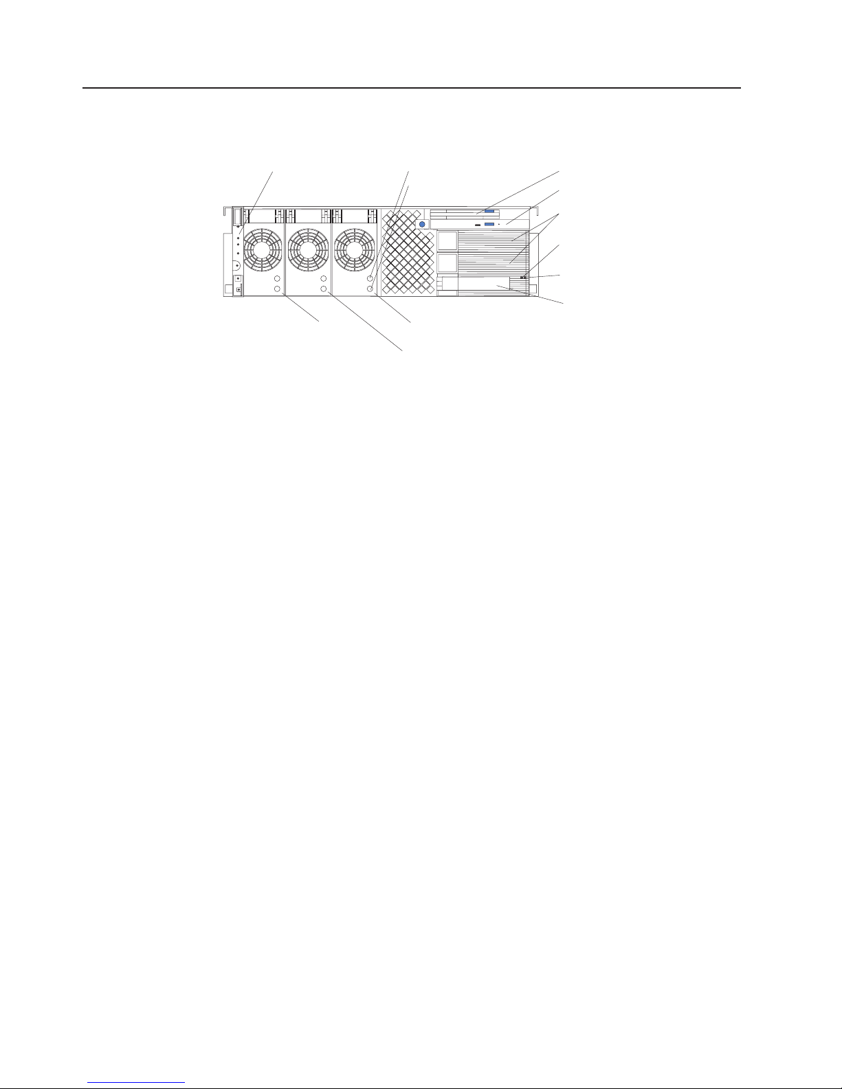
Controls and indicators
The following illustration shows the controls and indicators on the front of the
server.
Operator information
panel
AC LED
DC LED
Diskette drive
CD-ROM drive
Hard disk drive
filler panels
Activity
LED
(green)
Status
LED
(amber)
Hard disk drive
Power
supply 1
Power
supply 3
Power
supply 2
Operator information panel: This panel, also known as the front LED panel,
contains controls, indicators, and one of the three USB ports. See “Operator
information panel” on page 9 for details.
LED: Each hot-swap power supply has an ac power LED to indicate that ac
power is available to the power supply.
LED: Each hot-swap power supply has a dc power LED to indicate that the
power supply is active.
Diskette drive: The server contains one standard 3.5 diskette drive with an LED to
indicate when it is active.
CD-ROM drive: The server contains one standard IDE CD-ROM drive with an LED
indicate when it is active.
Hard disk drive filler panels: A filler panel is used to cover empty hard disk drive
bays. A filler panel must be installed in each empty bay to ensure proper system
cooling.
Activity LED: Each hot-swap hard disk drive has an activity LED, which flashes if
the drive is being accessed.
Status LED: Each hot-swap hard-disk drive has a status LED. If this amber LED is
continuously, the drive has failed. If an optional IBM ServeRAID
™
adapter is
installed in the server and the LED flashes slowly (one flash per second), the drive
being rebuilt. If the LED flashes rapidly (three flashes per second), the controller
identifying the drive.
Hard disk drive: The server supports a maximum of three hot-swap hard disk
drives.
Power supplies 1, 2, and 3: The server comes with a minimum of one hot-swap
power supply and supports a maximum of three hot-swap power supplies.
Hardware Maintenance Manual: xSeries 360 Type 8686
Page 19

The following illustration shows the indicators on the rear of the server.
Remote Supervisor
Adapter Ethernet port
Ethernet TX/RX LEDs
Ethernet link LEDs
Remote Supervisor
Adapter fault
LED
(amber)
Remote Supervisor
Adapter power LED
(green)
Ethernet port
Ethernet Link LEDs: These LEDs (one for the Remote Supervisor Adapter, one for
the network) indicate that the related Ethernet link is operational.
Ethernet TX/RX LEDs: These LEDs (one for the Remote Supervisor Adapter, one
for the network) indicate that activity is taking place on the related network.
Remote Supervisor Adapter Ethernet port: This port enables you to manage the
server from a remote location.
Remote Supervisor Adapter fault LED: This LED indicates that the Remote
Supervisor Adapter has failed.
Remote Supervisor Adapter power LED: This LED indicates that power is being
supplied to the Remote Supervisor Adapter.
Ethernet port: This port enables you to connect the server to a network.
Operator information panel
The following illustration shows the controls, indicators, and USB port on the
operator information panel (also known as the front LED panel).
USB port
SCSI bus activity LED
Information LED
Fault LED
USB port: This port enables you to attach a USB device to the front of the server.
Reset button
Power-control button
Power LED
Features overview
9
Page 20

it
to
or
1.
2.
to
3.
10
SCSI bus activity LED: This green LED is on when there is activity on the SCSI
bus.
Information LED: This amber light is on if the server power supplies are
nonredundant or some other noncritical event has occurred. See the LEDs on the
Level 2 diagnostic LED panel or on the system board for specific error information.
For details, see “Level 2 diagnostic and system board LEDs” on page 68.
Fault LED: This amber LED is on if a system error has occurred. See the LEDs on
the Level 2 diagnostic LED panel or on the system board for specific error
information. For details, see “Level 2 diagnostic and system board LEDs” on page
68.
Reset button: Press this button to reset the server and run the power-on self-test
(POST).
Power-control button: If the server is in operational mode, press this button to put
into standby mode. If the server is in standby mode, press this button to restore it
operational mode. See “Turning on the server” and “Turning off the server” on
page 11 for more information about applying and removing external power to the
server.
Power LED: This green LED is on if ac and dc power are present in the server. If
this LED is flashing, the server is in standby mode (ac power is present, but the
power supplies are turned off). If this LED is off, either ac power, all power supplies,
the light has failed.
Note: If this LED is off, it does not mean that there is no electrical power present in
the server. The LED might be burned out. To remove all electrical current
from the server, you must unplug the server power cords from the electrical
outlets.
Turning on the server
Turning on the server refers to the act of plugging the server power cords into the
power source and pressing the power-control button. After you install the network
operating system in the server, this typically causes the operating system to start.
Complete the following steps to turn on the server.
Turn on all external devices, such as the monitor.
Note: After you plug the power cords into the power source, wait 30 seconds
Plug the server power cords into the power source.
before pressing the power-control button on the operator information
panel. During this time, the Remote Supervisor Adapter is initializing and
the power-control button does not respond. The power LED on the
information panel blinks, indicating that ac power is present in the server.
Note: Plugging the power cords into the power source might cause the server
Wait 30 seconds; then, press the power-control button on the operator
information panel. The power LED comes on and the power-on self-test (POST)
begins.
Hardware Maintenance Manual: xSeries 360 Type 8686
start automatically. This is an acceptable action.
Page 21
on
If
a
1.
If the server is turned on and a power failure occurs, it restarts automatically when
power is restored. You can turn on the server remotely by means of the Remote
Supervisor Adapter.
When you start the server for the first time after you add or remove an internal
option or an external SCSI device, you might see a message telling you that the
configuration has changed. The Configuration/Setup Utility program automatically
starts so that you can save the new configuration information. See “Configuration”
page 27 for details.
Some options have device drivers that you need to install. See the documentation
that comes with the option for information about installing any required device
drivers.
The server comes with at least one microprocessor installed on the system board. If
you have installed one or more additional microprocessors, the server can now
operate as an SMP server. Therefore, you might need to upgrade the operating
system to support SMP. See “Using the ServerGuide CDs” on page 57 and the
operating system documentation for additional information.
the server has a ServeRAID adapter installed and you have installed or removed
hard disk drive, see the documentation that comes with the ServeRAID adapter
for information about reconfiguring the disk arrays.
Turning off the server
Turning off the server refers to the act of stopping the operating system, pressing
the power-control button, and disconnecting the server power cords from the power
source.
Statement 5:
CAUTION:
The power control button on the device and the power switch on the power
supply do not turn off the electrical current supplied to the device. The device
also might have more than one power cord. To remove all electrical current
from the device, ensure that all power cords are disconnected from the power
source.
2
1
See the operating system documentation for the proper procedure to shut down the
operating system before turning off the server. Each operating system is different.
Some allow an immediate shutdown; others require an orderly shutdown procedure.
Complete the following steps to turn off the server:
Press the power-control button on the operator information panel. This places
the server in standby mode. The power LED on the operator information panel
blinks. This does not remove all power from the server.
Features overview
11
Page 22

2.
1.
2.
12
Standby mode
Note: After doing this, wait at least 30 seconds before pressing the
power-control button to turn on the server again.
Disconnect the server power cords from the power source.
Note: Wait approximately 15 seconds after disconnecting the power cords for
the server to stop running. The power LED on the operator information
panel will stop blinking.
Standby mode refers to the condition in which the server operating system is not
running and all core logic is shut down except for the Remote Supervisor Adapter.
Complete the following steps to put the server into standby mode:
See the operating system documentation for the proper procedure to shut down
the operating system.
Note: Each operating system is different. Read all the documentation about
shutting down the operating system before continuing.
Press the power-control button on the front of the server.
can put the server into standby mode remotely by means of the Remote
You
Supervisor Adapter.
Hardware Maintenance Manual: xSeries 360 Type 8686
Page 23

If
v
14
v
v
of
©
Diagnostics
This chapter provides basic troubleshooting information to help you resolve some
common problems that might occur while setting up the server.
you cannot locate and correct the problem using the information in this chapter,
see “Symptom-to-FRU index” on page 115 for more information.
Diagnostic tools overview
The following tools are available to help you identify and resolve hardware-related
problems:
POST beep codes, error messages, and error logs
The power-on self-test (POST) generates beep codes and messages to indicate
successful test completion or the detection of a problem. See “POST” on page
for more information.
Diagnostic programs and error messages
The server diagnostic programs are stored in upgradable read-only memory
(ROM) on the system board. These programs are the primary method of testing
the major components of the server. See “Diagnostic programs and error
messages” on page 15 for more information.
Level 2 Light Path Diagnostics
The server has light-emitting diodes (LEDs) to help you identify problems with
server components. By following the light path, you can quickly identify the type
problem that occurred. The light path begins with the LEDs on the operator
information panel. See “Level 2 Light Path Diagnostics” on page 19 for more
information.
Copyright IBM Corp. 2003
13
Page 24

If
If
on
1. If
2. A
to
v
v
If
v A
v An
v
v An
v A
v An
v A
14
POST
When you turn on the server, it performs a series of tests to check the operation of
server components and some of the options that are installed in the server. This
series of tests is called the power-on self-test, or POST.
POST finishes without detecting any problems, a single beep sounds, and the first
screen of the operating system or application program appears.
POST detects a problem, more than one beep sounds, and an error message
appears on the screen. See “Beep symptoms” on page 115 and “POST error codes”
page 134 for more information.
Notes:
you have a power-on password or administrator password set, you must type
the password and press Enter, when prompted, before POST will continue.
single problem might cause several error messages. When this occurs, work
correct the cause of the first error message. After you correct the cause of
the first error message, the other error messages usually will not occur the next
time you run the test.
Error logs
The POST error log contains the three most recent error codes and messages that
the system generated during POST. The System Error log contains error messages
that were issued during POST and all system status messages from the Remote
Supervisor Adapter.
You can view the contents of the System Error log from either the
Configuration/Setup Utility program or from the diagnostic programs:
Start the Configuration/Setup Utility program; then, select Error Logs from the
main menu; then, select either Post Error Log or System Event/Error Log. See
“Starting the Configuration/Setup Utility” on page 28 for details.
Start the diagnostic programs; select Hardware Info from the top of the
diagnostic programs screen; select System Error Log from the list that appears;
then, follow the instructions on the screen. See “Starting the diagnostic
programs” on page 15 for details.
Small computer systems interface (SCSI) messages
you receive a SCSI error message while running the SCSISelect Utility program,
one or more of the following might be causing the problem:
failing SCSI device (adapter, drive, controller)
improper SCSI configuration
Duplicate SCSI IDs in the same SCSI chain
improperly installed SCSI terminator
defective SCSI terminator
improperly installed cable
defective cable
Hardware Maintenance Manual: xSeries 360 Type 8686
Page 25

v
v
v
v
on
be
To
1.
2.
If a
3.
4.
a. If
b.
c. If
d.
To solve the problem, verify that:
The external SCSI devices are turned on. You must turn on all external SCSI
devices before turning on the server.
The cables for all external SCSI devices are connected correctly.
The last device in each SCSI chain is terminated properly.
The SCSI devices are configured correctly.
you have verified these items and the problem remains, run the diagnostic
If
programs to obtain additional information about the failing device.
Diagnostic programs and error messages
The server diagnostic programs are stored in upgradable read-only memory (ROM)
the system board. These programs are the primary method of testing the major
components of the server.
Diagnostic error messages indicate that a problem exists; they are not intended to
used to identify a failing part. Troubleshooting and servicing of complex
problems that are indicated by error messages should be performed by trained
service personnel.
Sometimes the first error to occur causes additional errors. In this case, the server
displays more than one error message. Always follow the suggested action
instructions for the first error message that appears.
Starting the diagnostic programs
start the diagnostic programs:
Turn on the server and watch the screen.
When the message F2 for Diagnostics appears, press F2.
power-on password is set, the server prompts you for it. Type the power-on
password, and press enter.
When the Diagnostic Programs screen appears, select either Extended or
Basic from the top of the screen.
Select the test that you want to run from the list that appears; then, follow the
instructions on the screen.
Notes:
the server stops during testing and you cannot continue, restart the server
and try running the diagnostic programs again. If the problem remains, flash
the server with the latest diagnostics code and BIOS, and then run the test
again. If the problem remains, see “Undetermined problems” on page 143.
The keyboard and mouse (pointing device) tests assume that a keyboard
and mouse are attached to the server.
you run the diagnostic programs with no mouse attached to the server,
you will not be able to navigate between test categories using the Next Cat
and Prev Cat buttons. All other functions that are provided by
mouse-selectable buttons are also available using the function keys.
You can test the USB keyboard by using the regular keyboard test. The
regular mouse test can test a USB mouse. Also, you can run the USB
interface test only if there are no USB devices attached.
Diagnostics
15
Page 26

f.
is
is
is
cc is
is
16
the diagnostic programs do not detect any hardware errors but the problem
If
remains during typical server operations, a software error might be the cause. If you
suspect a software problem, refer to the information that comes with the software
package.
Error code format
This section shows the format of the error codes that might appear in the detailed
test log and summary log when running the diagnostic programs.
e.
You can view server configuration information (such as system configuration,
memory contents, interrupt request (IRQ) use, direct memory access (DMA)
use, device drivers, and so on) by selecting Hardware Info from the top of
the screen.
You can press F1 while running the diagnostic programs to obtain Help
information. You also can press F1 from within a help screen to obtain online
documentation from which you can select different categories. To exit from
the help information and return to where you left off, press Esc.
The error code format is as follows:
fff-ttt-iii-date-cc-text message
where:
fff
ttt
iii
date is the date that the diagnostic test was run and the error recorded.
text message
Text message format
This section shows the format of the diagnostic text messages that might appear in
the detailed test log and summary log when running the diagnostic programs.
The diagnostic text message format is as follows:
Function Name: Result (test specific string)
the three-digit function code that indicates the function being tested when
the error occurred. For example, function code 089 is for the
microprocessor.
the three-digit failure code that indicates the exact test failure that was
encountered.
the three-digit device ID.
the check value that is used to verify the validity of the information.
the diagnostic message that indicates the reason for the problem.
where:
Function Name
Result
Hardware Maintenance Manual: xSeries 360 Type 8686
The name of the function being tested when the error occurred.
This corresponds to the function code (fff) shown in the previous
list.
This can be one of the following:
Passed
This result occurs when the diagnostic test is completed
without any errors.
Page 27

it is
be
1.
2. To
1.
2. If
on
Failed This result occurs when the diagnostic test discovers an
error.
User Aborted
This result occurs when you stop the diagnostic test before
complete.
Not Applicable
This result occurs when you specify a diagnostic test for a
device that is not present.
Aborted
This result occurs when the test could not proceed, for
example, because of the system configuration.
Warning
This result occurs when a possible problem is reported
during the diagnostic test, such as when a device that is to
tested is not installed.
specific string
test
Additional information that you can use to analyze the problem.
Viewing the test log
When the tests have been completed, you can view the test log by selecting Utility
from the top of the screen and then selecting View Test Log.
Notes:
You can view the test log only while you are in the diagnostic programs. When
you exit the diagnostic programs, the test log is cleared (saved test logs are not
affected). To save the test log so that you can view it later, click Save Log on
the diagnostic programs screen and specify a location and name for the saved
log file.
save the test log to a diskette, you must use a diskette that you have
formatted yourself; this function does not work with preformatted diskettes. If the
diskette has sufficient space for the test log, the diskette may contain other
data.
For information about the system error log, see “Error logs” on page 14 and
“Configuration/Setup Utility main menu” on page 28.
Viewing the System Event/Error log
You can also view the System Event/Error log from the diagnostic programs. See
the instructions at “Error logs” on page 14.
Diagnostic error messages
Error messages may appear when you run the diagnostic programs.
Notes:
Depending on the server configuration, some of these error messages might not
appear when you run the diagnostic programs.
diagnostic error messages appear that are not listed, make sure that the
server has the latest levels of BIOS, Remote Supervisor Adapter, ServeRAID,
and diagnostics microcode installed.
For information about specific diagnostic error codes, see “Diagnostic error codes”
page 120.
Diagnostics
17
Page 28

If
v
v
1.
2.
3.
4.
5.
6.
7.
If
8.
9.
Do
18
Recovering the BIOS code
the BIOS has become damaged, such as from a power failure during a flash
update, you can recover the BIOS code using the flash ROM page swap jumper
(J56) and a BIOS flash diskette.
Note: Use one of the following methods to obtain a BIOS flash diskette:
Use the ServerGuide program to make a BIOS flash diskette.
Download a BIOS flash diskette from the World Wide Web at
http://www.ibm.com/pc/support.
flash memory of the server consists of a primary page and a backup page. The
The
J56 jumper controls which page is used to start the server. If the BIOS code in the
primary page is damaged, you can use the backup page to start the server; then,
start the BIOS flash diskette to restore the BIOS code to the primary page.
Complete the following steps to recover the BIOS:
Turn off the server and peripheral devices and disconnect all power cords and
external cables; then, remove the cover.
Locate jumper J56 (flash ROM page swap) on the system board. See “System
board locations” on page 65 for an illustration of the system board jumper
locations.
Move the jumper to pins 2 and 3 to enable BIOS recovery mode.
Reconnect all external cables and power cords and turn on the peripheral
devices.
Insert the BIOS flash diskette into the diskette drive and restart the server. The
system begins the power-on self-test (POST).
The Flash Update Utility program displays the Flash Update Menu. Select 1 -
Update POST/BIOS.
When prompted as to whether you want to move the current POST/BIOS
image to the backup ROM location, press N.
Attention:
secondary page.
When prompted as to whether you want to save the current code to a diskette,
press N.
When prompted to choose a language, select a language (from 0 to 7) and
press Enter to accept your choice.
10.
When prompted as to whether you want to change the serial number, ensure
that the correct serial number appears.
11.
When prompted as to whether you want to change the machine type, ensure
that the correct machine type appears.
12.
Attention:
Remove the flash diskette from the diskette drive.
13.
Turn off the server.
14.
Move the jumper on J56 to pins 1 and 2 to return to normal startup mode.
15.
Replace the cover and start the server.
you press Y, the damaged BIOS will be copied into the
not restart the server at this time.
Hardware Maintenance Manual: xSeries 360 Type 8686
Page 29
AC DC v 1
1
v 1
v 1
v 1
v
To
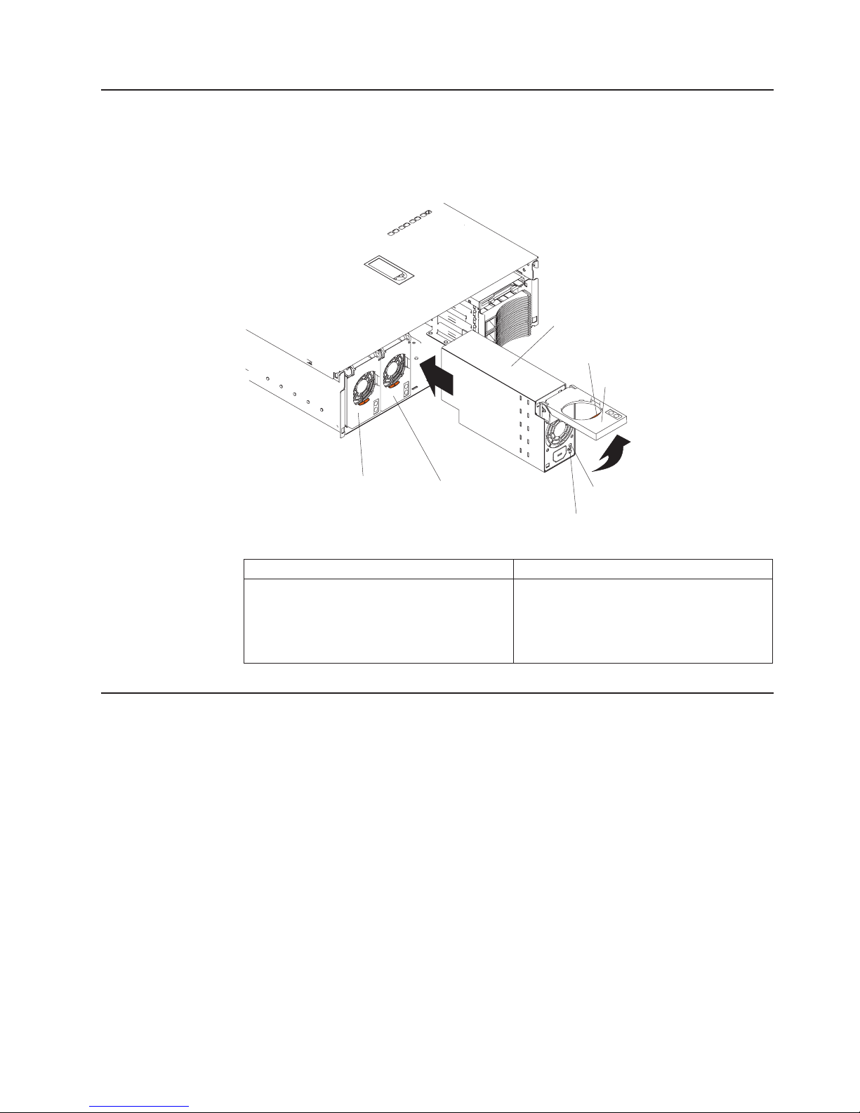
Power supply LEDs
The ac and dc power LEDs on a power supply provide status information about the
power supply. The following illustration shows the location of the ac and dc power
LEDs. For more information about interpreting the LEDs, see “Power supply LED
errors” on page 133.
Power supply 3
Locking latch
Locking handle
Power supply 1
Table 2. Power supply minimum configurations
power supply
Level 2 Light Path Diagnostics
The Light Path Diagnostics LEDs help you to identify problems with server
components. By following the light path, you can quickly identify and fix the type of
problem that occurred. The light path begins with the LEDs on the operator
information panel (also known as the front LED panel). If the server encounters a
problem, it lights either the Information LED or the Fault LED.
isolate the source of the trouble, examine the Level 2 Light Path Diagnostics
LEDs through the special cutout on the server top cover (shown at “Level 2
diagnostic panel LEDs” on page 20). These LEDs can indicate a problem with a
single component, or a problem with one of several similar components. In the latter
case, to isolate the specific failing component, remove the server top cover and
look for a lit LED on the system board, memory board, or failing component.
Power supply 2
AC power LED
DC power LED
v
power supply
power backplane
system board
processor in slot 1
Operator panel card
For example, if the FAN LED is lit, the specific failing fan is indicated by an LED
viewable with the top cover removed. If the MEM LED is lit, the specific failing
DIMM is indicated by an LED on the memory board.
Diagnostics
19
Page 30
on
SP
1.
2.
20
Level 2 diagnostic panel LEDs
The illustration at “Removing the server top cover and bezel” on page 72 shows the
location of the Level 2 diagnostic panel LEDs, visible through a special cutout area
the top cover. See “Level 2 Light Path troubleshooting” on page 21 for
information about using them to identify problems. The following illustration
identifies the diagnostic panel LEDs.
Over
See log
(CR17)
EXP
(CR8)
SP bus
(CR4)
NMI
(CR7)
Temp
(CR9)
Fan
(CR6)
Mem
(CR3)
PCI
(CR19)
CPU
(CR18)
VRM
(CR13)
DASD
(CR15)
Non
Redund
(CR16)
The meanings of these LEDs are as follows:
EXP
NMI
Over Temp
PCI
VRM
Attached expansion I/O failure
Nonmaskable interrupt
System over temperature condition
PCI failure
VRM failure
Out of
Spec
(CR14)
PS3
(CR10)
PS2
(CR11)
PS1
(CR12)
Remind
button
(SW1)
DASD
Out of Spec
PS2
Remind button
PS1
PS3
Non Redund
CPU
MEM
FAN
Bus
See Log
Hard disk drive failure
Power supplies being overdriven
Power supply number 2 failure
Remind to invoke remind mode
Power supply number 1 failure
Power supply number 3 failure
Nonredundant power mode
Microprocessor failure
Memory failure
Fan failure
Remote Supervisor Adapter failure
See event log or Remote Supervisor Adapter log for
non-optimal condition information
Notes:
The server supports replaceable voltage regulator modules (VRMs).
The server supports a maximum of three power supplies.
Hardware Maintenance Manual: xSeries 360 Type 8686
Page 31

v
v
v A
If
Remind button
You can use the Remind button to place the Fault light on the front panel into the
remind mode (blinks every 2 seconds). By pressing the button, you acknowledge
the failure but indicate that you will not take immediate action. If a new failure
occurs, the Fault light turns on again.
The Fault light stays in Remind mode until one of the following conditions occurs:
All known problems are resolved
The system is restarted
new problem occurs
can use the Remind button to delay server maintenance until a later time. In
You
this way, the light will indicate any subsequent error. If the light is still lit from the
first error, it is unable to indicate subsequent errors.
The Light Path Diagnostics feature might direct you to look for an LED on the
system board that identifies the specific failing component. The following illustration
identifies the LEDs on the system board.
Power backplane
LED (CR34)
PCI attention LED
PCI power LED
XA-32 chipset
VRM LED (CR29)
PCI switch card LED (CR 27)
Remote Supervisor Adapter
cable LED (CR28)
Microprocessor 4
VRM LED (CR20)
Microprocessor 4
LED (CR15)
Microprocessor 1
LED (CR4)
Microprocessor 1
VRM LED (CR2)
Microprocessor 3
LED (CR6)
Microprocessor 3
VRM LED (CR1)
Microprocessor 2
LED (CR8)
Microprocessor 2
VRM LED (CR21)
Level 2 Light Path troubleshooting
The Level 2 LEDs remain lit if the server shuts down, provided that the power
supplies are operating properly. This feature helps you to isolate the problem if an
error causes the server to shut down. For detailed information about the action to
take when the Level 2 Light Path Diagnostics indicate a problem, see “Level 2 light
path LED errors” on page 118.
the Level 2 Light Path Diagnostics indicate a problem that does not require
immediate action, you can press the Remind button on the diagnostic LED panel.
Diagnostics
21
Page 32

A
1.
2.
3.
4.
of
To
To
If
If
do
v
v
v
If
v
If
5
22
Power checkout
This causes the LED on the operator information panel to blink, reminding you that
you need to take action. The remind function enables normal operations to
continue, possibly using redundant components, until reduced server activity allows
you to correct the problem. The LED for the component causing the problem stays
lit until you make repairs.
Power problems can be difficult to troubleshoot. For instance, a short circuit can
exist anywhere on any of the power distribution busses. Usually a short circuit will
cause the power subsystem to shut down because of an overcurrent condition.
general procedure for troubleshooting power problems is as follows:
Power off the system and disconnect the AC cord(s).
Check for loose cables in the power subsystem. Also check for short circuits, for
instance if there is a loose screw causing a short circuit on a circuit board.
Remove adapters and disconnect the cables and power connectors to all
internal and external devices until system is at minimum configuration required
for power on (see “Undetermined problems” on page 143 for a description of the
minimum operating requirements).
Reconnect the AC cord and power on the system. If the system powers up
successfully, replace adapters and devices one at a time until the problem is
isolated. If system does not power up from minimal configuration, replace FRUs
minimal configuration one at a time until the problem is isolated.
use this method it is important to know the minimum configuration required for a
system to power up (see “Undetermined problems” on page 143 for a description of
the minimum operating requirements). For specific problems, see “Power error
messages” on page 140.
Error symptoms
find solutions to problems that have definite symptoms, see “Error symptoms” on
page 127.
you cannot find the problem in the table of error symptoms, go to “Starting the
diagnostic programs” on page 15 to test the server.
you have just added new software or a new option and the server is not working,
the following before using the error symptom charts:
Remove the software or device that you just added.
Run the diagnostic tests to determine if the server is running correctly.
Reinstall the new software or new device.
Ethernet controller troubleshooting
the Ethernet controller cannot connect to the network, check the following:
Make sure that the cable is installed correctly.
The network cable must be securely attached at all connections. If the cable is
attached but the problem remains, try a different cable.
you set the Ethernet controller to operate at 100 Mbps, you must use Category
cabling.
Hardware Maintenance Manual: xSeries 360 Type 8686
Page 33

v
v
–
–
v
v
v
v
If
To
If you directly connect two workstations (without a hub), or if you are not using a
hub with X ports, use a crossover cable.
Note: To determine whether a hub has an X port, check the port label. If the
label contains an X, the hub has an X port.
Determine if the hub supports auto-negotiation. If not, try configuring the
integrated Ethernet controller manually to match the speed and duplex mode of
the hub.
Check the Ethernet controller lights on the server rear panel.
These lights indicate whether a problem exists with the connector, cable, or hub.
The Ethernet Link Status light illuminates when the Ethernet controller
receives a LINK pulse from the hub. If the light is off, there might be a
defective connector or cable, or a problem with the hub.
The Ethernet Transmit/Receive Activity light illuminates when the Ethernet
controller sends or receives data over the Ethernet Network. If the Ethernet
Transmit/Receive Activity light is off, make sure that the hub and network are
operating and that the correct device drivers are loaded.
Check the LAN activity light (if available) on the rear of the server. The LAN
v
activity light is illuminated when data is active on the Ethernet network. If the
LAN activity light is off, make sure that the hub and network are operating and
that the correct device drivers are loaded.
Make sure that you are using the correct device drivers, which are supplied with
the server.
Check for operating-system-specific causes for the problem.
Make sure that the device drivers on the client and server are using the same
protocol.
Test the Ethernet controller.
The way you test the Ethernet controller depends on which operating system you
are using (see the Ethernet controller device driver README file).
The Ethernet wrap test can be used to determine if a hardware problem is
causing the Ethernet connection to fail. To perform the Ethernet wrap test, use
the wrap plug (FRU # 60G3981) in conjunction with the diagnostic tests.
the testing methods above indicate that the hardware is functioning normally
but the problem still exists, inform the network administrator.
Battery replacement
When replacing the battery, you must replace it with a lithium battery of the same
type from the same manufacturer. To avoid possible danger, read and follow the
safety statement below.
order replacement batteries, call 1-800-772-2227 within the United States, and
1-800-465-7999 or 1-800-465-6666 within Canada. Outside the U.S. and Canada,
call your IBM reseller or IBM marketing representative.
Note: After you replace the battery, you must reconfigure the system and reset the
system date and time.
Diagnostics
23
Page 34

a
Do
v
v
v
of
To
1.
2.
3.
4.
5.
a.
b.
c. To
24
Statement 2:
CAUTION:
When replacing the lithium battery, use only IBM Part Number 33F8354 or an
equivalent type battery recommended by the manufacturer. If your system has
module containing a lithium battery, replace it only with the same module
type made by the same manufacturer. The battery contains lithium and can
explode if not properly used, handled, or disposed of.
not:
Throw or immerse into water.
Heat to more than 100°C (212°F)
Repair or disassemble
Dispose
the battery as required by local ordinances or regulations.
replace the battery:
Read the information in “Before you begin” on page 71 and follow any special
handling and installation instructions supplied with the replacement battery.
Turn off the server and all attached devices, and disconnect all power cords and
external cables (see “Safety information” on page 145).
Remove the top cover as described at “Removing the server top cover and
bezel” on page 72.
Using the illustration at “System board locations” on page 65 as a reference,
locate the battery on the system board.
Remove the battery, as shown in the following illustration:
Use one finger to press down slightly on one side of the battery. The other
side of the battery will tilt up out of the socket.
Use your thumb and index finger to pull the battery out from under the
battery clip.
ensure that the battery clip will hold the replacement battery securely,
press gently on the clip so that it touches the base of the battery socket
momentarily.
Hardware Maintenance Manual: xSeries 360 Type 8686
Page 35

a.
b. As
7.
8.
of
9.
v
v
v
to
6.
Insert the new battery, as shown in the following illustration:
Tilt the battery so that you can insert it into the front of the socket, under the
battery clip.
you slide it under the battery clip, press the battery down into the socket.
Reinstall the top cover as described at “Installing the server top cover and
bezel” on page 95.
Reconnect the external cables and power cords; then, turn on the peripheral
devices and the server.
Note: You must wait approximately 30 seconds after you plug the power cord
the server into an electrical outlet before the power-control button
becomes active.
Start the Configuration/Setup Utility program and set configuration parameters.
Set the system date and time.
Set the power-on password.
Reconfigure the server.
Refer
“Using the Configuration/Setup Utility” on page 28.
Diagnostics
25
Page 36

26
Hardware Maintenance Manual: xSeries 360 Type 8686
Page 37

v
v
v
v
v
to
v
©
Configuration
You can use the following configuration programs to customize the settings for the
server hardware:
Configuration/Setup Utility program
This program is part of the basic input/output system (BIOS) code that comes
with the server. You can use this program to change interrupt request (IRQ)
settings, change the drive startup sequence, set the date and time, and set
passwords. For information about using this utility, see “Using the
Configuration/Setup Utility” on page 28.
SCSISelect utility program
This program is part of the basic input/output system (BIOS) code that comes
with the server. You can use this program to configure the devices that are
attached to the integrated SCSI controller. Use this program to change default
values, and to resolve configuration conflicts. For information about using this
utility, see “Using the SCSISelect utility program” on page 34.
PXE Boot Agent Utility program
The Preboot eXecution Environment (PXE) Boot Agent Utility program is part of
the BIOS code that comes with the server. You can use this program to select
the boot protocol and other boot options, to display the PXE setup prompt or to
disable it, to set the prompt display duration, and to select a power management
option. For information about using this utility, see “PXE Boot Agent Utility
program” on page 36
Note: The RPL selection for the Boot Protocol option is not supported for this
server.
ServerGuide CDs
The ServerGuide CDs provide software setup and installation tools that are
specifically designed for the server. Use these CDs during the initial installation of
the server to configure basic hardware features and to simplify network operating
system (NOS) installation. See “Using the ServerGuide CDs” on page 57 for
more information. The ServerGuide CDs also contain a collection of application
programs, which you can install after the server is up and running.
ServeRAID configuration program
This program comes with the optional ServeRAID adapters and with server
models that have a ServeRAID adapter preinstalled. If the server has a
ServeRAID adapter installed, you must use the ServeRAID configuration program
define and configure the disk-array subsystem before you install the operating
system. For more information about using the ServeRAID configuration program,
see “ServeRAID configuration program” on page 37 and also the ServeRAID
documentation that comes on the Documentation CD.
Remote Supervisor Adapter configuration process
Configuration activities are also required for the Remote Supervisor Adapter. See
“Remote Supervisor Adapter” on page 38 for information about setting up and
cabling the Remote Supervisor Adapter for use with an Advanced System
Management (ASM) network. For complete information about cabling,
configuring, and using the Remote Supervisor Adapter to manage the server
remotely, see the Remote Supervisor Adapter User’s Guide on the
Documentation CD.
Note: These configuration programs are not designed to help you configure the
Copyright IBM Corp. 2003
integrated Ethernet adapter.
27
Page 38

v
v
v
v
v
To
1.
2.
3.
1.
2.
28
To configure the integrated Ethernet controller, see “Configuring the
Ethernet controller” on page 37.
Using the Configuration/Setup Utility
Configuration/Setup is a menu-driven utility that is part of the BIOS code that comes
with the server. You can use it to:
Change the drive startup sequence
Enable USB keyboard and mouse support
Resolve configuration conflicts
Set the date and time
Set passwords
Starting the Configuration/Setup Utility
start the Configuration/Setup Utility program:
Turn on the server and watch the monitor screen.
When the message Press F1 for Configuration/Setup appears, press F1.
Follow the instructions that appear on the screen.
Configuration/Setup Utility main menu
From the Configuration/Setup Utility main menu, you can select settings that you
want to change.
Configuration/Setup Utility
•
System Summary
•
System Information
•
Devices and I/O Ports
•
Date and Time
•
System Security
•
Start Options
•
Advanced Setup
•
Error Logs
Save Settings
Restore Settings
Load Default Settings
Exit Setup
<F1> Help < > < > Move
<Esc> Exit <Enter> Select
Notes:
You can press F1 to display help information for a selected menu item.
The choices on some menus might differ slightly, depending on the BIOS code
version in the server.
↑↓
Hardware Maintenance Manual: xSeries 360 Type 8686
Page 39

v
v
–
–
–
– If
– If
v
–
The following choices are available from the main menu:
System Summary
Select this choice to display configuration information. This includes the type and
speed of the microprocessors and the amount of memory that is installed.
Changes that you make to configuration settings appear on this summary screen.
You cannot edit the fields.
This choice appears on both the full and limited Configuration/Setup Utility
menus.
System Information
Select this choice to display information about the server. Changes that you
make on other menus might appear on this summary screen. You cannot edit
any fields. The System Information choice appears only on the full
Configuration/Setup Utility main menu.
Product Data
Select this choice to view system information, such as the machine type and
model, serial number, and the revision level or issue date of the BIOS code
that is stored in the flash electrically erasable programmable ROM
(EEPROM).
System Card Data
Select this choice to view vital product data (VPD) for some server
components.
Devices and I/O Ports
v
Select this choice to view or change the assignments for devices and
input/output ports. This choice appears only on the full Configuration/Setup Utility
main menu.
You can use this choice to enable or disable the integrated SCSI, video, and
Ethernet controllers.
The default setting is Enable for all the controllers. If you select Disable, the
system will not configure the disabled device, and the operating system will
not detect the device. (This is equivalent to unplugging the device.)
the on-board SCSI controller is disabled and no other controller and mass
storage device is installed, operating-system startup cannot occur.
the video controller is disabled and no video adapter is installed, the server
will have no video capability.
Date and Time
v
Select this choice to set the system date and time and to change the system
time that is sent to the Remote Supervisor Adapter when the server is started.
This choice appears only on the full Configuration/Setup Utility main menu.
The system time is in a 24-hour format: hour:minute:second.
You can set a time delta to be added or subtracted from the system time that is
sent to the Remote Supervisor Adapter each time the server is started. Use the
number keys to type the hours and minutes and + or − to add or subtract from
the system time. If you want the system clock time to be the same as the
Remote Supervisor Adapter clock time, leave the value set at its default of 0.
System Security
Select this choice to set passwords or the remote control security settings. You
can implement three levels of password protection. This choice appears only on
the full Configuration/Setup Utility main menu.
You can implement the following levels of password protection:
Power-on Password
Configuration
29
Page 40

–
be
–
on
–
If
–
If
–
If
A
–
30
Select this choice to set or change a power-on password. See “Power-on
password” on page 32 for more information.
Administrator Password
Select this choice to set or change an administrator password.
Attention: If an administrator password is set and then forgotten, it cannot be
overridden or removed. The operator information panel card must be
replaced; see “Operator panel card” on page 108.
The administrator password provides access to all choices on the
Configuration/Setup Utility main menu. You can set, change, or delete both
the administrator and power-on passwords and allow a power-on password to
changed by the user.
See “Administrator password” on page 33 for more information.
Remote-Control Security Settings
Select this choice to set the password for remote access to the server. You
can set the number of failed logins before the server cuts off access. See
“Remote-control security settings” on page 34 for more information.
Start Options
v
Select this choice to view or change the start options. This choice appears only
the full Configuration/Setup Utility main menu. Start options take effect when
you start the server.
You can select keyboard operating characteristics, such as whether the keyboard
number lock starts on or off, and the keyboard speed. You also can enable the
server to run without a diskette drive, display, or keyboard.
The server uses a startup sequence to determine the device from which the
operating system starts. For example, you can define a startup sequence that
checks for a startable diskette in the diskette drive, then checks the hard disk
drive in bay 1, and then checks a network adapter.
USB Legacy
you enable this option, you can use a USB keyboard on a non-USB-aware
operating system. The supported environments are DOS and System Setup.
Note that if a PS/2
®
keyboard is detected, the USB Legacy operation will be
disabled regardless of the value of this setting.
Boot Fail Count
the option is enabled, you can restore the BIOS system defaults after three
consecutive boot failures. If this option is disabled, the BIOS system defaults
can be loaded only from the Configuration/Setup Utility main menu.
Virus Detection
you enable this option, a virus-detection test checks for changes in the
master boot record at startup.
Advanced Setup
v
Select this choice to change values for advanced hardware features, such as
cache control, and PCI/PCI-X configuration. This choice appears only on the full
Configuration/Setup Utility main menu.
warning message appears above the choices on this menu to alert you that the
system might malfunction if these options are configured incorrectly. Follow the
instructions on the screen carefully.
System Partition Visibility
Select this choice to specify whether the System Partition is visible. To make
the System Partition visible, set this value to Visible. To make the System
Hardware Maintenance Manual: xSeries 360 Type 8686
Page 41

on
–
–
-
-
–
If a
–
–
–
Partition invisible, set this value to Hidden. See “Using the ServerGuide CDs”
page 57 for additional information on the System Partition.
Boot Device Location
Select this choice to determine whether the server boots from the system
board SCSI device or from an adapter in an expansion slot.
PCI Slot/Device Information
Select this choice to view system resources used by installed PCI/PCI-X
devices. PCI/PCI-X devices are usually configured automatically. This
information is saved when you exit. The Save Settings, Restore Settings,
and Load Default Settings choices on the Configuration/Setup Utility main
menu do not save the PCI Slot/Device Information settings.
Attention:
You must use the menu selections to save custom settings for
the PCI Slot/Device Information choice. The Save Settings, Restore
Settings, and Load Default Settings choices on the Configuration/Setup
Utility main menu do not save the PCI Slot/Device Information settings.
After making changes, select:
Save and exit the PCI utility to save the changes and return to the
Advanced Setup screen.
Exit the PCI utility without saving changes to ignore the changes,
restore the previous settings, and return to the Advanced Setup screen.
Cache Control
–
Select this choice to enable or disable the microprocessor cache. In addition,
you can set the microprocessor cache mode as write-back (WB) or
write-through (WT). Selecting write-back mode provides better system
performance. The default settings enable the cache and set the mode as
write-back.
Memory Settings
Select this choice to manually enable a bank of memory.
memory error is detected during POST or memory configuration, the
server can automatically disable the failing memory bank and continue
operating with reduced memory capacity. If this occurs, you must manually
enable the memory bank after the problem is corrected. Select Memory
Settings from the Advanced Setup menu, and use the arrow keys to highlight
the bank that you want to enable; then, use the arrow keys to select Enable.
Integrated System Management Processor Settings
Select this choice to specify the Reboot System on NMI option. You can use
this option to enable or disable automatic reboot after a NonMaskable
Interrupt (NMI) occurs.
Error Logs
v
Select this choice to view or clear error logs.
Select POST Error Log to view the three most recent error codes and
messages that the system generated during POST.
Select Clear Event/Error Logs from the POST Error Log menu to clear the
error log.
Select System Event/Error Log to view the System Event/Error log. The
System Event/Error log contains all the system error and warning messages
that the system has generated. You can use the arrow keys to move between
pages in the System Event/Error log.
Select Clear Event/Error Logs from the System Event/Error Log menu to
clear the error or event log.
Configuration
31
Page 42

v
v
v
If
or
v If an
v
v
1.
2.
3.
32
v
Save Settings
Select this choice to save your customized settings.
Restore Settings
Select this choice to delete your changes and restore the previous settings.
Load Default Settings
Select this choice to cancel your changes and restore the factory settings.
Exit Setup
you have made any changes, the program will prompt you to save the changes
exit without saving the changes.
Using passwords
The System Security choice appears only on the full Configuration/Setup Utility
menu. After you select this choice, you can implement two levels of password
protection: power-on password and administrator password.
Power-on password
When a power-on password is set, POST is not completed until you type the
password. After you set a power-on password, you can enable the unattended-start
mode. This locks the keyboard and mouse but allows the system to start the
operating system. The keyboard and mouse remain locked until you type the
correct password.
You can use any combination of up to seven characters (A–Z, a–z, and 0–9) for
your power-on password. Keep a record of your password in a secure place. If you
forget the power-on password, you can regain access to the server through one of
the following methods:
administrator password is set, type the administrator password (see
“Administrator password” on page 33) at the power-on prompt. Start the
Configuration/Setup Utility program and change the power-on password.
Change the position of the power-on password override jumper as described at
“Using the password override jumper.”.
Remove the battery and then install the battery.
Using the password override jumper
Change the position of the password override jumper by using the following
procedure:
Read the information at “Safety information” on page 145.
Turn off the server and disconnect all power cords and external cables, and
remove the top cover.
Change the position of the jumper on J52 to bypass the power-on password
check. You can then reconnect all external cables and power cords, start the
Configuration/Setup Utility program and change the power-on password.
Hardware Maintenance Manual: xSeries 360 Type 8686
Page 43

on
4.
The following illustration shows the power-on password override jumper (J52)
the system board.
Power-on password
override jumper (J52)
3
2
1
Flash ROM
page swap jumper (J56)
Changing the position of the jumper on J52 bypasses the power-on password
check if the jumper has been moved since the server was last powered on. You
must move the jumper back to the default position after the password is
overridden. The default position is pins 1 and 2.
Changing the position of this jumper does not affect the administrator password
check if an administrator password is set.
Install the top cover.
Administrator password
Select this choice to set an administrator password. The administrator password
provides access to all choices on the Configuration/Setup Utility main menu. You
can set, change, or delete both the administrator and power-on passwords and
allow a power-on password to be changed by the user.
Attention: If an administrator password is set and then forgotten, it cannot be
overridden or removed. You must replace the operator information panel (see
“Operator panel card” on page 108).
3
2
1
Configuration
33
Page 44

v
v
v No
v
v
v
v
v
to
v
v
is
v
v
To
1.
2.
34
The following table provides a summary of the password features.
Table 3. Power-on and administrator password features
Type of password
Power-on password
Administrator password
Administrator and
power-on password
Results
Type the password to complete the system startup.
All choices are available on the Configuration/Setup Utility main
menu.
password is required to start the system.
Type the password to access the Configuration/Setup Utility
program.
All choices are available on the Configuration/Setup Utility main
menu.
You can type either password to complete the system startup.
The administrator password provides access to all choices on
the Configuration/Setup Utility main menu. You can set,
change, or delete both the administrator and power-on
passwords and allow a power-on password to be changed by
the user.
The power-on password provides access to a limited set of
choices on the Configuration/Setup Utility main menu. This
limited access might include changing or deleting the power-on
password.
Remote-control security settings
Select this choice to set a remote-control password, which provides remote access
all choices on the Configuration Setup Utility main menu. You can set the
following features:
Set or read current Remote Supervisor Adapter
Set lockout threshold. Enter a number of failed login attempts. Once this number
reached, the server locks up. You can also set the server to lock up if no
password is entered for a set number of minutes.
“Remote Supervisor Adapter” on page 38 for information on cabling and
See
configuring the Remote Supervisor Adapter.
Using the SCSISelect utility program
SCSISelect is a built-in, menu-driven configuration utility program that you can use
to:
View the default SCSI IDs
Locate and correct configuration conflicts
Note: If the server has a redundant arrays of independent disks (RAID) adapter
installed, use the configuration method that is supplied with the RAID
adapter to view or change SCSI settings for devices attached to the adapter.
Starting the SCSISelect utility program
start the SCSISelect utility program:
Turn on the server.
When the <<< Press <CTRL><A> for SCSISelect Utility! >>> prompt appears,
press Ctrl+A.
Hardware Maintenance Manual: xSeries 360 Type 8686
Page 45

to
3.
4.
v
v
v
–
–
–
–
–
-
-
-
To
5.
SCSISelect menu
The following choices are available from the SCSISelect utility menu:
Note: If an administrator password has been set, a prompt appears asking you
type the password to start the SCSISelect utility program.
When the Would you like to configure the host adapter or run the SCSI
disk utility? question appears, make a selection and press Enter.
Use the arrow keys to select a choice from the menu.
Press Esc to exit from the SCSISelect utility program.
Press the F5 key to switch between color and monochrome modes (if the
monitor permits).
Follow the instructions on the screen to change the settings of the selected
items; then, press Enter.
Configure/View Host Adapter Settings
Select this choice to view or change the SCSI controller settings. To reset the
SCSI controller to its default values, press F6; then, follow the on-screen
instructions.
You can view or change the following controller settings:
Host Adapter SCSI ID
Select this choice to view the SCSI controller ID, which is usually 7.
SCSI Parity Checking
Select this choice to view the assigned value. The assigned value is Enabled,
and it cannot be changed.
Host Adapter SCSI Termination
Select this choice to view the assigned value. The assigned value is Enabled,
and it cannot be changed.
Boot Device Options
Select this choice to configure startable-device parameters. Before you can
make updates, you must know the ID of the device whose parameters you
want to configure.
SCSI Device Configuration
Select this choice to configure SCSI device parameters. Before you can make
updates, you must know the ID of the device whose parameters you want to
configure.
Note: The Sync Transfer Rate represents the transfer rate for Ultra SCSI
Advanced Configuration Options
–
Select this choice to view or change the settings for advanced configuration
options.
v
SCSI Disk Utilities
Select this choice to view the SCSI IDs that are assigned to each device or to
format a SCSI device.
use the program, select a drive from the list. Read the screens carefully
before making a selection.
devices.
The transfer rate for Ultra160 SCSI LVD devices is 160.0 Mbps.
The transfer rate for Ultra2 SCSI LVD devices is 80.0 Mbps.
The transfer rate for Fast SCSI devices is 20.0 MBps.
Configuration
35
Page 46

v
v
v
To
1.
2.
a. If
b. By
v
v
v
v
v
v
v
v
36
Note: If you press Ctrl+A before the selected drives are ready, an Unexpected
SCSI Command Failure screen might appear. Restart the server and
watch the SCSISelect messages as each drive spins up. After the drive
that you want to view or format spins up, press Ctrl+A.
PXE Boot Agent Utility program
This program is a built-in, menu-driven configuration utility program that you can
use to:
Select whether to display setup prompt
Set menu wait time
Select legacy operating-system wake-up support
Attention: The network startup protocols and startup order options are not
supported on this product.
Starting the PXE Boot Agent Utility program
start the PXE Boot Agent Utility program:
Turn on the server.
When the Initializing Intel Boot Agent Version X.X (Dev Build XXX)
prompt appears, press Ctrl+S.
Notes:
the PXE setup prompt does not display, use the Configuration/Setup Utility
program to set the enable Ethernet PXE/DHCP option.
default, you have 2 seconds after the prompt appears on the screen to
press Ctrl+S.
Use the arrow keys or press Enter to select a choice from the menu.
3.
Press Esc to return to the previous menu.
Press the F4 key to exit.
Follow the instructions on the screen to change the settings of the selected
4.
items; then, press Enter.
PXE Boot Agent Utility menu
The following choices are available from the PXE Boot Agent Utility menu:
Boot Protocol
PXE is the default value for this menu item.
Note: Do not change this value. There are no other network boot protocols
supported.
PnP/BEV
PnP is the default value.
Default Boot
Local is the default value.
Local Boot
Enabled is the default value.
Prompt time
Select this choice to set the amount of time (in seconds) that the system will
pause during initialization for a Ctrl+S response to the PXE setup prompt. The
default value is 2.
Setup Message
Hardware Maintenance Manual: xSeries 360 Type 8686
Page 47

If
v
1.
2. If
3.
is on
A
To
is an
Select this choice to either display the PXE setup prompt or disable it. Disable is
the default setting.
this choice is enabled, Press Ctrl+S to enter the setup menu will appear on
the screen under the initializing prompt.
Power Mgmt
Select this choice to specify a power management protocol.
Notes:
Use the default setting for Advanced Configuration and Power Interface
(ACPI)-aware operating systems, such as Microsoft Windows
®
2000 and
Windows NT®.
the server is running a non-ACPI operating system, you must set this
selection to Enable to use the Wake on LAN support.
When using a non-ACPI operating system, do not send a wake-up packet to the
server while it is turned on. If a wake-up packet has been sent while the server
and you are unable to turn the server off, see the ″Power″ section in “Error
symptoms” on page 127 for more information.
ServeRAID configuration program
ServeRAID adapter enables you to use multiple physical SCSI hard-disk drives as
logical drives, operating as a disk array. To enable you to configure the ServeRAID
controller, the adapter comes with a CD containing the ServeRAID Manager
program and the ServeRAID Mini-Configuration program. For details about using
these programs, see the documentation that comes with the ServeRAID adapter.
Configuring the Ethernet controller
The server comes with an integrated Ethernet controller. This controller provides an
interface for connecting to 10-Mbps or 100-Mbps networks and provides full-duplex
(FDX) capability, which enables simultaneous transmission and reception of data on
the Ethernet local area network (LAN).
use the Ethernet port, connect an appropriate (Category 5 is recommended)
unshielded twisted-pair (UTP) cable to the RJ-45 connector on the rear of the
server.
Note: The 100BASE-TX Fast Ethernet standard requires that the cabling in the
network be Category 5 or higher.
The Ethernet (RJ-45) connectors on the rear panel and on the Remote Service
Adapter each have two lights. When the green Ethernet link-status light is on, there
active connection on the Ethernet port. When the amber Ethernet
transmit/receive activity light is on, there is activity between the server and the
network. For a description of the Ethernet port, see “Ethernet port” on page 100.
When you connect the server to the network, the Ethernet controller automatically
detects the data-transfer rate (10 Mbps or 100 Mbps) on the network and then sets
the controller to operate at the appropriate rate. In addition, if the Ethernet port that
the server is connected to supports auto-negotiation, the Ethernet controller will set
the appropriate duplex state. That is, the Ethernet controller will adjust to the
network data rate, whether the data rate is standard Ethernet (10BASE-T), Fast
Ethernet (100BASE-TX), half duplex (HDX), or full duplex (FDX). The controller
supports half-duplex (HDX) and full-duplex (FDX) modes at both speeds.
Configuration
37
Page 48

to
If
v
v
v
v
v
v
v
v
v
v
v
v
v
38
The Ethernet controller is a PCI Plug and Play device. You do not need to set any
jumpers or configure the controller for the operating system before you use the
controller. However, you must install a device driver to enable the operating system
access the controller. The device driver is provided on the ServerGuide CDs.
you install an optional Ethernet adapter, you can use it together with the
integrated Ethernet controller to support optional modes, such as teaming, priority
packets, and virtual LANs, which provide higher performance and throughput for the
server. These modes apply to the integrated Ethernet controller and to the
controllers on the supported Ethernet adapters.
Remote Supervisor Adapter
This section identifies the Remote Supervisor Adapter features, prerequisites, and
recommendations. It also explains how to use the documentation effectively and
how to cable and configure the adapter for use on an Advanced System
Management (ASM) network so that you can manage the server from a remote
location. For more detailed information see the Remote Supervisor Adapter User’s
Guide on the Documentation CD.
Remote Supervisor Adapter features
The Remote Supervisor Adapter provides the following:
Continuous health monitoring and control
Advanced Predictive Failure Analysis (PFA)
Configurable notification and alerts
Event logs that are timestamped, saved in nonvolatile memory, and can be
attached to e-mail alerts
Remote graphics console redirection
LAN, serial, and Advanced System Management (ASM) interconnect remote
access
Point-to-point protocol (PPP) support
Simple Network Management Protocol (SNMP)
Domain Name System (DNS) and Dynamic Host Configuration Protocol (DHCP)
support
Remote power control
Microsoft
®
Windows NT and Windows 2000 blue-screen capture
Remote firmware update and access to critical server settings
Optional independent power, which enables around-the-clock access to the
server even if the server is powered off
Setup requirements
Before you set up the Remote Supervisor Adapter, you must download to a diskette
the DOS Remote Supervisor Utility program from the World Wide Web at
http://www.ibm.com/pc/support.
The most current Remote Supervisor Adapter firmware and the management
information base (MIB) automatically download to the same diskette. However, the
firmware and MIB available on the ServerGuide CD are fully functional; it is not
necessary to install either one unless you want the most current items. You need
the MIB if you plan to configure Simple Network Management Protocol (SNMP) trap
alerts on the Remote Supervisor Adapter.
Hardware Maintenance Manual: xSeries 360 Type 8686
Page 49

v
v
v If
on
v
–
–
v To
UM
v If
–
–
–
–
–
–
v
v
in
Do the following before you set up the Remote Supervisor Adapter.
Install the operating system on the server, using ServerGuide and the
documentation that comes with the operating system.
Download to a diskette the most current server basic input/output system (BIOS)
code from the World Wide Web at http://www.ibm.com/pc/support. Install the
BIOS code using the instructions that download to the diskette.
you plan to configure Simple Network Management Protocol (SNMP) trap alerts
the Remote Supervisor Adapter, you must install and compile the
management information base (MIB) on your SNMP manager.
You must install the agent component of UM Server Extensions to use the
following Advanced System Management (ASM) Web interface features:
Shutdown O/S and then Power Off Server
Shutdown O/S and then Restart Server
Server Extensions is on the system-management software CD that comes
UM
with the server. For information about installing the agent component, see the
documentation that comes with the system-management CD.
configure the remote alert recipients for Director over LAN or Director over
modem, the remote alert recipient must be an IBM Director-enabled server with
Server Extensions.
you want to use a Web browser to access the Remote Supervisor Adapter
remotely, the supported Web browsers and browser requirements are:
Microsoft Internet Explorer 4.0 (with Service Pack 1), or later
Netscape Navigator 4.72, or later (version 6.0 is not currently supported)
™
Java
enabled Web browser (See your browser documentation or online Help
for instructions about enabling its Java support.)
Support for JavaScript
™
1.2, or later (See your browser documentation or
online Help for instructions about enabling its JavaScript support.)
Support of HTTP version 1.0, or later
Minimum display resolution of 800 x 600 pixels and 256 colors
Note:
The ASM Web interface and the ASM text-based interface do not support
the double-byte character set (DBCS) languages.
Using the documentation
The documentation for the Remote Supervisor Adapter includes the following
publications on the xSeries 360 Documentation CD.
IBM Eserver xSeries 360 User’s Reference (this document, specifically the
topics in this section, which assist you with cabling and configuring)
Remote Supervisor Adapter User’s Guide for the IBM Eserver xSeries 360
This document explains how to configure and use an ASM network to manage
the server remotely through either the Web-based interface or the text-based
user interface.
Cabling and configuring the Remote Supervisor Adapter
This section explains how to cable and configure the Remote Supervisor Adapter.
The following tasks are necessary to accomplish this.
Note: After you initially configure the adapter, use the Web-based interface to
create a backup copy of the configuration. If you need to replace the adapter
the future, this enables you to restore the configuration and resume
Configuration
39
Page 50

1.
2.
3.
3.
If
on
on
40
normal operation more quickly. See the Remote Supervisor Adapter User’s
Guide for the Eserver xSeries 360 for details.
Task 1.
Connect the Ethernet and serial port cables. See “Cabling the Ethernet LAN
port and serial port.”
Task 2.
Perform the initial configuration to enable remote access to the Remote
Supervisor Adapter. See “Enabling remote access to the adapter” on page
42. This enables you to:
Configure the Ethernet port
Configure the serial (COM) port
Set up the point-to-point protocol
Task
Configure the remote control password to enable the ASM Web interface
remote control features. See “Configuring the remote control password” on
page 50.
Task 4.
Install the ASM device drivers. See “Installing Advanced System
Management device drivers” on page 47.
Cabling the Ethernet LAN port and serial port
This section describes how to cable the Remote Supervisor Adapter. You can
manage the server remotely through the Remote Supervisor Adapter using one of
the user interfaces and one of the connection methods that are described in
Table 4. Choose the interface method you want to use to perform remote
management; then, perform the indicated cabling procedure.
you plan to set up an ASM interconnect network, before you begin cabling the
server, see “Using the ASM interconnect network” on page 50 for instructions about
cabling the ASM interconnect port and setting up the network. You might want to
review the information in “ASM interconnect network configuration examples” on
page 54 before you connect the cables. Then, return here to start the cabling
procedures.
Table 4. Cabling tasks to enable remote access to the Remote Supervisor Adapter
User interface to Remote
Supervisor Adapter
ASM Web interface using
the HTTP protocol
Text-based user interface
using the TELNET protocol
Text-based user interface
using a modem or a null
modem
ASM Web interface using
point-to-point (PPP)
protocol
Text-based user interface
using the TELNET protocol
over PPP
Connection to Remote
Supervisor Adapter
LAN using the Ethernet port
Serial (COM) port
For the cabling procedure,
see:
“Cabling the Ethernet LAN port”
page 41
“Cabling the serial (COM) port”
page 41
Hardware Maintenance Manual: xSeries 360 Type 8686
Page 51

1.
2.
To
or
v
v
Cabling the Ethernet LAN port:
Complete the following steps to attach the
Ethernet cables.
Attention: To avoid damage to the Ethernet connector on the Remote Supervisor
Adapter, do not plug the ASM Interconnect module into the Ethernet port.
Connect one end of an appropriate Ethernet cable (Category 5 is
recommended) to the Ethernet port on the Remote Supervisor Adapter. Connect
the other end of the Ethernet cable to the network.
Check the Ethernet LEDs to ensure that the network connection is working. The
following illustration shows the location of the LEDs.
Ethernet link
LED (green)
Ethernet activity
LED (green)
ASM Interconnect port
(RJ-14)
-
P
P
Ethernet port
(RJ-45)
Serial port
(COM)
P
P
Error LED
(amber)
External power
supply connector
Ethernet link LED
Ethernet activity LED
you want to use the serial port connection, continue with “Cabling the serial
If
(COM) port”; otherwise, go to “Configuring the adapter.”
Cabling
the serial (COM) port:
null modem cable to the serial port on the Remote Supervisor Adapter.
Continue with “Configuring the adapter.”
Configuring the adapter
This section describes the following:
Enabling remote access to the Remote Supervisor Adapter
Installing ASM device drivers
Power LED
(green)
The green Ethernet link LED is lit when the Ethernet cable is connected
properly.
The green Ethernet activity LED flashes when there is Ethernet activity.
cable the serial (COM) port, connect a modem
These
procedures assume that you have an operational keyboard and pointing
device attached to the server.
Configuration
41
Page 52

on
45
If
an
go to
If
1.
2.
3.
4.
42
Enabling remote access to the adapter
The Remote Supervisor Adapter requires configuration to enable remote access
through either the Ethernet port or the serial port. From Table 5, choose the
interface method that you want to use to perform remote management; then,
perform the indicated configuration procedure.
Note: For detailed information about using the ASM Web interface and the
text-based user interface, see the Remote Supervisor Adapter User’s Guide
the xSeries 360 Documentation CD.
Table 5. Configuration tasks to enable remote access to the Remote Supervisor Adapter
User interface to Remote
Supervisor Adapter
ASM Web interface using
the HTTP protocol
Text-based user interface
using the TELNET protocol
Text-based user interface
using a modem or a null
modem
ASM Web interface using
point-to-point (PPP)
protocol
Text-based user interface
using the TELNET protocol
over PPP
Connection to Remote
Supervisor Adapter
For the configuration
procedure, see:
LAN using the Ethernet port “Configuring the Ethernet
settings for Web-based remote
access”
Serial (COM) port
“Configuring the serial port for
test-based remote access” on
page 43 and “Setting up
point-to-point protocol” on page
Configuring the Ethernet settings for Web-based remote access:
you have
accessible, active, and configured dynamic host configuration protocol (DHCP)
server on the network, the hostname, IP address, gateway address, subnet mask,
and DNS server IP address are set automatically. You do not need to perform
further configuration tasks to enable the Ethernet connection because the default
value for the DHCP Setting field is Enabled. If you need to configure the serial port,
“Configuring the serial port for test-based remote access” on page 43;
otherwise, go to “Configuring the remote control password” on page 50.
you do not have a DHCP server on the network, complete the following steps to
configure the Ethernet settings.
With the server turned off, insert the diskette with the downloaded utility
program into the diskette drive; then, turn on the server.
The utility starts automatically, displaying the Remote Supervisor Utility
window.
Use the Up Arrow and Down Arrow keys (↑ and ↓) to select Configuration
Settings; then, press Enter. The Configuration Settings window opens.
Use the arrow keys to select Ethernet Settings; then, press Enter.
The Ethernet Settings window opens, as shown in the following illustration.
Hardware Maintenance Manual: xSeries 360 Type 8686
Page 53

5.
IP
6.
7.
8.
9.
If
If
Note: The values in the window are only examples; your settings will be
different.
Use the arrow keys to navigate to each field. Your system administrator can
provide the information for the following fields:
Network Interface
The default value is Enabled; verify that it is still set to Enabled.
Address
Type the IP address of the Remote Supervisor Adapter.
Subnet Mask
Type the subnet mask used by the Remote Supervisor Adapter. The
default value is 255.255.255.0.
Gateway
Type the IP address of the gateway.
Host Name
Type the hostname of the Remote Supervisor Adapter. The default
hostname is ASMA<burned-in MAC address>.
detailed information about the Ethernet settings, see the Remote
For
Supervisor Adapter User’s Guide on the xSeries 360 Documentation CD.
Change the DHCP Setting field to Disabled. The default value is Enabled.
Press F6 to apply the change.
Press Esc. In the Warning window that opens, press Enter to restart the
Remote Supervisor Adapter.
Press Esc to return to the Configuration Settings window.
you need to configure the serial port, go to “Configuring the serial port for
test-based remote access.”
10.
Press Esc to return to the Utility program main window.
11.
Use the arrow keys to select Exit Utility from the menu or press Esc to close
the Utility program.
12.
Remove the diskette from the diskette drive. The server restarts automatically.
13.
you also want to configure the serial port, continue with “Configuring the
serial port for test-based remote access.” Otherwise, go to “Installing Advanced
System Management device drivers” on page 47.
Configuring
following steps to configure the Remote Supervisor Adapter serial port for access
the serial port for test-based remote access:
Complete the
Configuration
43
Page 54

1.
2.
3.
4.
5.
If
44
using a modem or null modem. If you completed the procedure for configuring the
Ethernet port and the Configuration Settings window is open, go to step 4.
With the server turned off, insert the diskette with the downloaded utility
program into the diskette drive; then, turn on the server.
The utility starts automatically, displaying the Remote Supervisor Utility
window.
Use the Up Arrow and Down Arrow keys (↑ and ↓) to select Configuration
Settings; then, press Enter.
The Configuration Settings window opens.
Use the arrow keys to select Modem Settings; then, press Enter.
The Modem Settings window opens, as shown in the following illustration.
Note: The values in the window are only examples; your settings might be
different.
Verify the following serial port values:
Baud Rate
The default is 57600. Make sure that the baud rate matches the baud
rate of the device you are connecting to the serial port on the Remote
Supervisor Adapter.
Dedicated to ASM
The default is Disabled. If you are using point-to-point protocol (PPP),
set this field to Enabled. If the value in this field is Enabled when the
server is restarted, the serial port remains dedicated to system
management and is not returned to the operating system.
You can dedicate the integrated serial port on the Remote Supervisor
Adapter to system management or share it with the operating system.
the serial port is dedicated to system management, it serves only the
Remote Supervisor Adapter and is always available for dial-in or
dial-out alerting purposes. You cannot view the port using the
operating system or any application.
Note: To use this serial port, you must first install the ASM device
drivers as described in “Installing Advanced System
Management device drivers” on page 47.
Hardware Maintenance Manual: xSeries 360 Type 8686
Page 55

6. If
7.
If
8.
9.
up
a
1.
2.
3.
4.
If the serial port is shared with the operating system, it is dedicated to
the Remote Supervisor Adapter only while the server is turned off or
during POST. The port is returned to the operating system after POST
completes. You can view the port using the operating system or any
application. The Remote Supervisor Adapter takes over the port from
the operating system only when information about a critical event is
received. The Remote Supervisor Adapter dials out and transmits an
alert and keeps the port dedicated until the server is restarted. The
port is no longer available to the operating system or applications.
Parity
The default is None.
Stop Bits
The default is 1.
Note:
The data bits value is preset to 8 and cannot be changed.
For detailed information about the serial port and modem settings, see the
Remote Supervisor Adapter User’s Guide on the xSeries 360 Documentation
CD.
you made changes to the serial port settings, press F6 to apply the change.
Press Esc to return to the Configuration Settings window.
you need to set up point-to-point protocol, go to “Setting up point-to-point
protocol.”
Press Esc to return to the Utility program main window.
Use the arrow keys to select Exit Utility from the menu, or press Esc to close
the Utility program.
10.
Remove the diskette from the diskette drive. The Remote Supervisor Adapter
restarts automatically.
11.
Continue with “Setting up point-to-point protocol.”
Setting
point-to-point protocol:
The Remote Supervisor Adapter serial port
supports point-to-point protocol (PPP). PPP enables TCP/IP communication over
the serial port, which enables Web-based management and TELNET sessions over
modem. To set up PPP, complete the following steps. If you completed the
procedure for configuring the serial port and the Configuration Settings window is
open, go to step 4
With the server turned off, insert the downloaded utility program into the
diskette drive; then, turn on the server.
The utility starts automatically, displaying the Remote Supervisor Utility
window.
Use the Up Arrow and Down Arrow keys (↑ and ↓) to select Configuration
Settings; then, press Enter.
The Configuration Settings window opens.
Use the arrow keys to select PPP Settings; then, press Enter.
The PPP Settings window opens, as shown in the following illustration.
Configuration
45
Page 56

5.
IP
6.
7.
8.
If
9.
46
Note: The values in the window are only examples; your settings will be
different.
Use the arrow keys to navigate to each field. Verify the values in the following
fields:
Network Interface
The default is Disabled. Change this field to Enabled.
Address
The default value is 192.96.1.1. You can use the default value or
another value, but the server must be able to establish a connection to
that address. The default IP address (local and remote) is easily
reconfigurable.
Subnet Mask
The default value is 255.255.255.255.
Line Type
The value is set to PPP.
Remote IP Address
The default value is 192.96.1.2.
Authentication Protocol
The default is CHAP then PAP. Make sure that the value in this field
matches your client settings.
detailed information about the PPP settings, see the information about
For
configuring PPP access over a serial port in the Remote Supervisor Adapter
User’s Guide on the xSeries 360 Documentation CD.
Press F6 to apply the changes.
Press Esc. In the Warning window that opens, press Enter to restart the
Remote Supervisor Adapter.
Press Esc to return to the Configuration Settings window.
you need to configure the serial port, go to “Configuring the serial port for
test-based remote access” on page 43.
Press Esc to return to the Utility program main window.
10.
Use the arrow keys to select Exit Utility from the menu or press Esc to close
the Utility program.
11.
Remove the diskette from the diskette drive. The server restarts automatically.
Hardware Maintenance Manual: xSeries 360 Type 8686
Page 57

is
1. If
v
v
If
is
v
v
49 v
To
1. Do
2. If
1.
2. If
3. If
4.
5. Go to
12.
Continue with “Installing Advanced System Management device drivers.”
Installing Advanced System Management device drivers
You must install the ASM device drivers for the server. The device drivers enable
communication between the Remote Supervisor Adapter and the server in which it
installed. You can obtain the most current device drivers from the World Wide
Web at http://www.ibm.com/pc/support/.
The following sections describe the procedure for installing the ASM device drivers
for the server, depending on your operating system.
Notes:
you are installing device drivers manually, note the following requirements:
Make sure that the operating system is installed on the server before you
install the ASM device drivers. For information about installing the operating
system, see the documentation that comes with the operating system.
Before installing the ASM device drivers for the Remote Supervisor Adapter,
stop any system-management application.
2.
you are using ServerGuide to install device drivers and your operating system
either Microsoft Windows NT or Windows 2000, ServerGuide installs the ASM
device drivers automatically.
Windows 2000: Continue with “Installing Windows 2000 ASM device drivers”
v
Windows NT: Go to “Installing Windows NT ASM device drivers” on page 48
Novell NetWare: Go to “Installing Novell NetWare ASM device drivers” on page
SCO UnixWare: Go to “Installing SCO UnixWare ASM device drivers” on page 49
After you install the ASM device drivers, go to “Configuring the remote control
password” on page 50 to set the remote control password.
Installing Windows 2000 ASM device drivers:
install the ASM device drivers
for Windows 2000, complete the following steps.
Notes:
not use the Hardware Wizard to install the drivers. If the Hardware Wizard
starts itself for the installation of any System Management Driver hardware, exit
the Hardware Wizard by selecting Cancel.
IBM Netfinity
®
Director, IBM Director, or UM Services is running on the server,
stop the system-management application before proceeding.
Complete the following steps to manually install the Windows 2000 ASM device
drivers.
Open a command prompt.
you are installing from a diskette, type: A:\WIN2000\SETUP, where A is the drive
letter of the diskette drive.
you are installing from the IBM Remote Supervisor Adapter Support CD, type:
D:\DD\WIN2000\SETUP, where D is the drive letter of the CD-ROM drive.
Follow the directions that display on the screen.
“Configuring the remote control password” on page 50.
Configuration
47
Page 58

v
v
to
If
is
1.
v If
v If
3. Go to
1.
v If
v If
3.
48
Installing Windows NT ASM device drivers:
Choose one of the following
methods to install the ASM device drivers for Windows NT:
Non-interactive
The non-interactive method for installing the ASM device drivers accepts the
default values for any window prompts that appear. You are prompted to respond
only if an error occurs during installation.
Interactive
The normal (interactive) method, prompts you with instructions and waits for you
respond before continuing with the installation.
Note:
IBM Netfinity Director, IBM Director, UM Services, or IBM Netfinity
Manager
™
running on the server, stop the system-management application
before proceeding.
the non-interactive method:
Using
Complete the following steps to use the
non-interactive method.
Open a Windows NT command prompt; then, type one of the following
commands:
the installation is from a diskette, type:
A:\NT\SETUP -q
(where A is the drive letter assigned to the diskette drive).
Press Enter.
the installation is from a CD, type:
D:\DD\NT\SETUP -q
(where D is the drive letter assigned to the CD-ROM drive).
Press Enter.
2.
Follow the instructions that appear in the window.
“Configuring the remote control password” on page 50.
the interactive method:
Using
Complete the following steps to use the interactive
method.
Open a Windows NT command prompt; then, type one of the following
commands:
the installation is from a diskette, type:
A:\NT\SETUP
(where A is the drive letter assigned to the diskette drive).
Press Enter.
the installation is from a CD, type:
D:\DD\NT\SETUP
(where D is the drive letter assigned to the CD-ROM drive).
Press Enter.
2.
Follow the instructions that appear in the window.
Continue with “Configuring the remote control password” on page 50.
Hardware Maintenance Manual: xSeries 360 Type 8686
Page 59

1.
v If
v If
3. Go to
v
1.
2.
3.
4.
5.
1.
2. If
3. If
4.
1.
2. If
3. If
4.
Installing Novell NetWare ASM device drivers:
Complete the following steps to
install the ASM device drivers for the Novell NetWare operating system:
Note: If IBM Netfinity Director, IBM Director, or IBM Netfinity Manager is running on
the server, stop the system-management application before proceeding.
From a system console session, type one of the following commands:
the installation is from a diskette, type:
LOAD A:\NETWARE\SETUP
(where A is the drive letter assigned to the diskette drive).
Press Enter.
the installation is from a CD, type:
LOAD D:\DD\NETWARE\SETUP
(where D is the drive letter assigned to the CD-ROM drive).
Press Enter.
Follow the instructions that appear in the window.
2.
“Configuring the remote control password” on page 50.
Installing
SCO UnixWare ASM device drivers:
Choose one of the following
methods to install the SCO UnixWare ASM device drivers.
Note: If IBM Netfinity Director or IBM Director is running on the server, stop it
before proceeding.
Complete the following steps to use the SCO UnixWare package utility:
Open a shell prompt.
Type scoadmin and press Enter.
Click Application Installer.
Click to access the diskette or CD-ROM drive (for example, DISK_A or
CD-ROM_1); then, install the package file that displays.
Continue with “Configuring the remote control password” on page 50.
Complete the following steps to use the interactive installation from a shell
v
prompt:
Note: The commands in the following steps are case-sensitive.
Open a shell prompt.
pkgadd -d diskette1
pkgadd -d cdrom1
Continue with “Configuring the remote control password” on page 50.
v
Complete the following steps to use the non-interactive installation from a shell
prompt:
Note: The commands in the following steps are case sensitive.
Open a shell prompt.
pkgadd -d diskette1 -q-p-n uw7advmg
pkgadd -d cdrom1 -q-p-n uw7advmg
Continue with “Configuring the remote control password” on page 50.
the installation is from a diskette, type:
the installation is from a CD, type:
the installation is from a diskette, type:
the installation is from a CD, type:
Configuration
49
Page 60

If
of
To
1.
2.
3.
4.
5.
6.
7. In
8.
9.
To
v
v
v
v
An
50
Configuring the remote control password
you want to use the remote control features of the Remote Supervisor Adapter
ASM Web interface, you must configure the remote control password using the
Configuration/Setup Utility program that comes with the server. This program is part
the basic input/output system (BIOS) code.
set up a remote control password, complete the following steps:
Boot up the server, and watch the monitor screen.
When the message Press F1 for Configuration/Setup is displayed, press F1.
The Configuration/Setup Utility main menu window opens.
Use the Up Arrow and Down Arrow keys (↑ and ↓) to select System Security;
then, press Enter. The System Security window opens.
Select Remote Control Security Settings; then, press Enter. The Remote
Control Security Settings window opens.
Enter the Remote Control Password that you will use each time you log into
the remote control features of the Remote Supervisor Adapter ASM Web
Interface.
Select Save New Remote Control Password; then, press Enter.
the System Security window, press Esc.
Select Save Settings; then, press Enter.
Confirm your selection; then, exit the Configuration/Setup Utility.
10.
Continue with “Completing the configuration.”
Completing the configuration
complete the configuration of the Remote Supervisor Adapter, see the Remote
Supervisor Adapter User’s Guide on the xSeries 360 Documentation CD. The tasks
include the following:
Defining the login IDs and passwords
Selecting the events that will receive alert notification
Monitoring remote server status using the ASM Web interface or a text-based
user interface
Controlling the server remotely
you want to set up an ASM interconnect network and have not already done so,
If
continue with “Using the ASM interconnect network.” If you do not want to set up an
ASM interconnect network, Remote Supervisor Adapter configuration is now
complete. To start managing the server remotely, see the Remote Supervisor
Adapter User’s Guide on the xSeries 360 Documentation CD.
Using the ASM interconnect network
This section explains how to configure and connect the server to function within an
ASM interconnect network.
The ASM interconnect network can include as many as 12 individual ASM
connections in a single bus. These connections can include Remote Supervisor
Adapters, ASM processors, and ASM PCI Adapters. When the clients and servers
are connected, they use the ASM interconnect network to share ASM resources,
information, and alerts among multiple servers, without having to add additional
communications hardware or network interface adapters.
ASM interconnect network provides two levels of functionality. First, the ASM
interconnect network enables you to configure settings and to control the servers
Hardware Maintenance Manual: xSeries 360 Type 8686
Page 61

on
an
To
To
v
v
v It is
where other Remote Supervisor Adapters, ASM processors, and ASM PCI Adapters
the network reside. Second, the ASM interconnect network enables other
interconnect network devices to use the resources (Ethernet or modem) of other
Remote Supervisor Adapters, ASM processors, and ASM PCI Adapters in the ASM
interconnect network for sending alerts. This interconnect network is used when
Remote Supervisor Adapters, ASM processors, or ASM PCI Adapters cannot send
alert and must forward the information to another one of these devices to send
the alert.
Planning and cabling the interconnect network
support the most recent ASM features, a Remote Supervisor Adapter must be
the main gateway interconnect to the ASM interconnect bus if the bus also includes
servers with ASM PCI adapters or ASM processors. The Remote Supervisor
Adapter forwards the ASM information generated by the servers attached to the
ASM interconnect bus to other servers on the Ethernet network. The connected
ASM processors and ASM PCI Adapters are managed through the new user
interface and Web browser access of the Remote Supervisor Adapter.
Note: To ensure the stability of the system, you must have the most current level of
firmware installed on the Remote Supervisor Adapter that is the main
interconnect gateway for the ASM interconnect network. The most current
level of firmware is available on the World Wide Web at
http://www.ibm.com/support.
You must connect an ASM Interconnect module to the Remote Supervisor Adapter
and to each server that you connect to the ASM interconnect network bus.
Attention: To avoid damage to the Ethernet connector on the Remote Supervisor
Adapter, do not plug the ASM Interconnect module into the Remote Supervisor
Adapter Ethernet port.
connect the servers, note the following setup and configuration considerations:
Make sure that the ASM interconnect network is set up as a bus, not as a ring.
You must connect the servers to the ASM interconnect network in a series, with
terminated beginning and end points.
Make sure that the total combined length of all Ethernet cables connecting the
v
server in the ASM interconnect network does not exceed 91 M (300 ft).
Each Remote Supervisor Adapter, ASM PCI adapter, or ASM processor that is
connected to the ASM interconnect network bus counts as one connection. For
example, if an ASM PCI adapter is installed in a server that has an ASM
processor, the processor and the adapter connect to each other using one ASM
interconnect connection, but the processor and the adapter count as two
connections on the ASM interconnect network bus.
advisable that the most current level of firmware is installed on the Remote
Supervisor Adapter that is the gateway for the interconnect network. For more
information on updating firmware, see the Remote Supervisor Adapter User’s
Guide for the Eserver xSeries 360 on the Documentation CD.
Forwarding alerts
Remote Supervisor Adapters, ASM PCI adapters, and ASM processors that are
connected to an ASM interconnect network share resources and
system-management information. This section provides information on how alerts
are forwarded in the ASM interconnect network.
Configuration
51
Page 62

If
If
52
During normal operation, each Remote Supervisor Adapter, ASM processor, or ASM
PCI adapter on the ASM interconnect network communicates with the other
processors and adapters on the network. Processors or adapters that have a
modem or Ethernet connection notify the other processors and adapters that these
communications resources are available for use by other servers on the ASM
interconnect network. These resources are then used as ASM interconnect network
resources, enabling Remote Supervisor Adapters, ASM processors, or ASM PCI
adapters on the ASM interconnect network to send alerts using a modem or the
network, even if they do not have a modem or network connection physically
attached.
When alerts are generated, they are forwarded to the Remote Supervisor Adapter,
ASM processor, or ASM PCI adapter on the ASM interconnect network that has the
communication resources to forward the alert. If no system on the ASM interconnect
network meets the requirements, the alert is set for transmission if the connection
type is configured or becomes available later.
multiple modems or network connections exist in the ASM interconnect network,
you cannot specify which system will receive an alert or which will use its modem or
network connection to forward the alert. If an alert is forwarded to a Remote
Supervisor Adapter, ASM processor, or ASM PCI adapter that is unable to deliver
the alert (for example, the modem it is configured to use has failed or the network
cannot resolve the destination IP address), the processor or adapter attempts to
forward the alert to another system on the ASM interconnect network that has the
communication resources to forward the alert.
Alerts are typically sent only once (per connection type), but an alert is forwarded to
another interconnect device if the resources exist on other interconnect devices in
the network. For example, on a three ASM processor network where ASM
processor 1 generates a modem alert, but does not have a modem and the other
ASM processors have modems, the following might occur:
ASM processor 1 generates an alert and the modem is unplugged from ASM
processor 2 45 seconds prior to ASM processor 1 generating the alert, ASM
processor 1 forwards the alert to ASM processor 2, having previously determined
that ASM processor 2 has an available modem. When ASM processor 2 receives
the forwarded alert, it determines that a modem is attached to ASM processor 3,
and forwards the alert. Therefore, depending upon the time frame (45 seconds)
within which a resource (modem) fails, the alert might be forwarded multiple times
until an interconnect device can send the alert.
Cabling for the ASM interconnect network
Depending upon the servers you have, you might need additional ASM Interconnect
modules or appropriate Ethernet cables (Category 5 recommended). Table 6 lists
some IBM Netfinity and IBM xSeries products, and indicates whether you need to
use an ASM Interconnect module to set up the ASM interconnect network.
Table 6. ASM interconnect network server list
Server Name
Netfinity 4500R
Netfinity 5000
Netfinity 5500
Netfinity 5500-M10
Netfinity 5500-M20
ASM Interconnect module needed
yes
yes
yes
yes
yes
Hardware Maintenance Manual: xSeries 360 Type 8686
Page 63

no
no
no
no
1.
2.
3.
Table 6. ASM interconnect network server list (continued)
Server Name
Netfinity 5600
ASM Interconnect module needed
yes
Netfinity 6000R
Netfinity 7100
Netfinity 7600
xSeries 220
xSeries 232
xSeries 240
xSeries 330
yes
yes
yes
The ASM interconnect module is required to link
the Remote Supervisor Adapter to the
microprocessor in the server. Use the RS-485
ports to create the ASM interconnect network.
xSeries 340
xSeries 342
yes
yes
xSeries 350
xSeries 360
yes
For the servers that do not need an ASM Interconnect module, a module is still
needed to connect the Remote Supervisor Adapter in the gateway server to the
integrated ASM processor. After you make that connection, you can connect the
servers together using their ASM interconnect ports. For additional information, see
“ASM interconnect network configuration examples” on page 54.
Connecting the ASM Interconnect module to the xSeries 360:
The ASM
Interconnect module connects the Remote Supervisor Adapter to the ASM
interconnect network. This module comes with the server. To connect the ASM
interconnect cable to the Remote Supervisor Adapter, complete the following steps.
Attention: To avoid damage to the Ethernet connector, do not plug the ASM
interconnect cable into the Remote Supervisor Adapter Ethernet port.
Connect the ASM Interconnect module 1 to the Remote Supervisor Adapter
ASM interconnect (peer-to-peer) port 2 as shown in the following illustration.
This port is labeled RS485 on the rear panel of the server.
Connect one or two Ethernet cables of the appropriate type (Category 5 is
recommended) to the other end of the ASM Interconnect module.
Continue with “ASM interconnect network configuration examples” on page 54.
Configuration
53
Page 64

54
ASM interconnect network configuration examples
The illustrations in this section show sample ASM interconnect network
configurations.
The following illustration shows an Ethernet cable connecting the remote
administrator system to the Remote Supervisor Adapter that is installed in an
xSeries 360. Server 1 uses the LAN connection to forward system-management
data generated by the other servers in the ASM interconnect network bus to the
remote system-management administrator.
Remote system
management administrator system
Ethernet
Remote
Supervisor
Adapter
Note: A Remote
Supervisor Adapter is
required in each server.
Note: The ASM Interconnect module is connected to the RS485 port on the
back panel of the Remote Supervisor Adapter in each server.
xSeries 360
Server 1
xSeries 360
Server 3
xSeries 360
Server 2
ASM
Interconnect
modules
Hardware Maintenance Manual: xSeries 360 Type 8686
Page 65

The following illustration shows a modem connected to the serial port of the
Remote Supervisor Adapter in the xSeries 360 on the left, a modem connected to
the serial port of the Remote Supervisor Adapter in the xSeries 360 on the right,
and a modem connected to the remote administrator system. Placing modems at
opposite ends of the ASM interconnect network bus ensures that if an ASM
interconnect connection in the bus fails, all of the servers on the ASM interconnect
network have access to a modem to forward system-management data to the
remote system-management administrator.
Remote system management
Modem
administrator system
xSeries 360
Modem
xSeries 360
xSeries 360
Note: A Remote
Supervisor Adapter is
required in each server.
Note: The ASM Interconnect module is connected to the RS485 port on the
back panel of the Remote Supervisor Adapter in each server.
Modem
ASM
Interconnect
modules
Configuration
55
Page 66

56
Hardware Maintenance Manual: xSeries 360 Type 8686
Page 67

If a
v An
v
v
v A
v
v
v
©
Using the ServerGuide CDs
The ServerGuide CDs include easy-to-use software setup tools and installation
tools that are specifically designed for the IBM server. The ServerGuide Setup and
Installation program detects the server model and hardware options that are
installed and uses that information during setup to configure the hardware. The
ServerGuide tools simplify network operating system (NOS) installations by
providing updated device drivers, and in some cases, installing them automatically.
later version of the ServerGuide software is available, you can download a free
image of the software To download the latest ServerGuide software, see the
ServerGuide page on the IBM Support Web site at:
http://www.ibm.com/pc/qtechinfo/MIGR-4ZKPPT.html.
The ServerGuide software has these features to make setup easier:
easy-to-use interface with online help
Diskette-free setup and configuration programs that are based on detected
hardware
Performance Optimizer program, which easily tunes the ServeRAID adapter
settings for the server environment
system BIOS update program, which updates the BIOS directly from the CD
Device drivers that are provided for your server model and detected hardware
NOS partition size and file-system type that are selectable during setup
Powerful application programs and administration tools
Copyright IBM Corp. 2003
57
Page 68

an
v
v
v
v
v
v
v
v
v
CD v
v
v
v
58
Features at a glance
The following is a summary of ServerGuide features.
Note: Specific features and functions can vary with different versions of the
ServerGuide software. To learn more about the version that you have, start
the Setup and Installation CD and view the online Overview.
Setup and Installation CD
Note: The ServerGuide program
requires a supported IBM server with
enabled startable (bootable)
CD-ROM drive. Not all features are
supported on all models.
Sets system date and time.
Detects the ServeRAID adapter or
controller and runs the ServeRAID
configuration program.
Updates the licensed internal code
(firmware) level without creating
diskettes.
Checks the system BIOS code and
microcode (firmware) levels of
supported options to determine
whether a later level is available
from the CD. You can perform
updates without the use of
diskettes.
Provides the Performance
Optimizer program to easily tune
the ServeRAID adapter settings for
the server environment.
Creates a System Partition on the
default drive. You can run
server-specific utility programs after
setup.
Setup and Installation CD
(continued)
Detects installed hardware options
and provides updated device
drivers for most adapters and
devices.
Creates a Setup Replication
Diskette for replicating setup
selections for other servers of the
same model.
v
Provides diskette-free installation
for supported operating systems.
v
Provides a replicated installation
path for multiple installations of
supported operating systems.
Includes an online README file
with links to tips for the hard-ware
and NOS installation.
Installation requires the NOS
Note:
CD.
System Updates and Applications
Creates diagnostic, RAID, device
driver, and other support diskettes
from the CD; or with an Internet
connection, you can check for an
update from a dedicated IBM file
transfer protocol (FTP) server.
Installs some updates without
requiring diskettes. Where
applicable, you can run executable
files directly from the CD or unzip
files to any drive on the server or
another server on the network.
v
Includes a vast library of fully tested
device drivers for the server.
Includes a search function to help
you locate updates by title or
keywords.
Installs powerful applications
directly from the CD. See the CD
label for a current list of
applications.
Setup and configuration overview
When you use the Setup and Installation CD, you do not need setup diskettes. You
can use the CD to configure any supported IBM server model. The setup program
checks the system BIOS code, Remote Supervisor Adapter, and other system
hardware to determine whether system updates are available. The setup program
provides a list of tasks that are required to set up the server model. On RAID
servers, you can run the ServeRAID Manager program to create logical drives.
Note: Specific features and functions can vary with different versions of the
ServerGuide software.
Hardware Maintenance Manual: xSeries 360 Type 8686
Page 69

v
v
–
–
–
If
–
–
on
–
–
–
–
1.
2.
When you start the Setup and Installation CD:
You are prompted for the language, country, and keyboard layout. (This
information is stored and later passed on to the NOS installation program.)
The ServerGuide program displays choices for running the configuration
programs. For example:
The Express Configuration method runs the required programs for the server,
based on the hardware that is detected.
The Custom Configuration method displays all programs that are available for
the server, and you decide which programs to run.
The Replicated Configuration method provides the option of duplicating your
setup selections to other servers that are the same model.
you select the Custom Configuration method, the following programs are
v
optional. If you select the Express Configuration method, some or all of these
programs are run, depending on the hardware that is detected.
The Set Date and Time feature is provided so that you do not have to use the
Configuration/Setup Utility program to access these settings.
The Clear Hard Disks program is provided so that you can delete all partitions
all hard disk drives. If the server has a ServeRAID adapter installed, you
can select to restore the configuration on the ServeRAID adapter to the
factory default settings.
The ServerGuide program checks the server BIOS code and microcode
(firmware) levels for supported options and then checks the CD for a newer
level. CD content can be newer than the hardware. The ServerGuide program
can perform a flash update of the BIOS code and supported microcode
(firmware) options without the use of diskettes.
The ServeRAID program starts, guiding you through the entire configuration
process.
The Performance Optimizer program easily tunes the server for your
environment.
The ServerGuide program creates a System Partition on the default drive.
The ServerGuide program displays a confirmation summary, so that you will
v
know when you have completed all the required tasks. Then, you are ready to
install the NOS.
Notes:
Plug and Play adapters are configured automatically. Non-Plug and Play
adapters or non-IBM adapters might require switch settings, additional device
drivers, and installation after the NOS is installed. See the documentation that
comes with the adapter.
Diagnostics for the server come in BIOS code or on a separate diagnostics CD.
Using the ServerGuide CDs
59
Page 70

on
v
v
v
v
v If
At
60
System partition
The ServerGuide program creates a 50 MB system partition on the default drive.
The System Partition contains server-specific utility programs such as Remote
Supervisor Adapter disk operating system (DOS) utilities, system diagnostics, flash
BIOS updates, and other programs.
Note: Programs in the System Partition vary by server model, and not all server
models run utility programs from the System Partition. To determine which
ones do, start the Setup and Installation CD and view the online Overview.
After setup is complete, you can access programs in the System Partition by
restarting the server and pressing Alt+F1 when the prompt is displayed. The System
Partition menu displays the programs that are available on the server model.
Typical NOS Installation
You can use the ServerGuide program to shorten the installation time. The
ServerGuide program provides the necessary device drivers, based on the
hardware that you have and the NOS that you are installing. If you prefer to install
the NOS without using ServerGuide, go to “Installing the NOS without ServerGuide”
page 61 for details.) The following is a brief explanation of a typical ServerGuide
NOS installation.
Note: Specific features and functions can vary with different versions of the
ServerGuide software
After you have completed the setup process, the operating system installation
program starts. (You will need a copy of the NOS CD to complete the
installation.)
The ServerGuide program stores information about the server model, Remote
Supervisor Adapter, hard disk controllers, and network adapters. It then checks
the CD for newer device drivers. This information is stored and then passed to
the NOS installation program.
With some NOS installations, you can create a NOS Replication Diskette for
setting up additional servers. The diskette will contain the Internet protocol (IP)
address, server name, and other selections.
The ServerGuide program presents NOS partition options that are based on your
NOS selection and the installed hard disk drives.
you are installing the NOS from diskette, the ServerGuide program displays the
required diskettes that you must create, and the optional diskettes that you might
want to create. The diskettes that you can create are the device driver diskettes
for the installed adapters or controllers.
ServerGuide program prompts you to insert the NOS CD and restart the server.
The
this point, the installation program for the NOS takes control to complete the
installation.
Setting up or updating multiple servers
You can use the ServerGuide program to create diskettes that help you set up or
update multiple servers. You can modify information on the diskettes as you use
them to set up or update other servers.
Hardware Maintenance Manual: xSeries 360 Type 8686
Page 71

is
If
1. Go to
2.
3.
4. On
5.
If
As a
A
CD
Note: Availability and function can vary by server model and by the hardware that
installed.
You can create a Setup Replication Diskette, which contains your hardware
configuration selections. Use this diskette to replicate selections to other servers
that are of the same model.
You can create a NOS Replication Diskette, which contains information that you
need to complete multiple installations. This feature supports servers running some
operating systems.
Installing the NOS without ServerGuide
you have already configured the server hardware and you decide not to use the
ServerGuide program to install the NOS, download the latest NOS installation
instructions:
http://www.ibm.com/pc/support.
From the Browse the support site menu, click Servers.
From the Family menu, click xSeries 360.
the left side of the page, click OS Installation to see the list of installation
instructions for the supported operating systems.
From the Operating System installation by Category menu, select a
supported operating system to see the list of installation instructions.
Note:
you select Microsoft Windows NT 4.0 as the NOS, do not install the
network adapter driver that comes with that product. It does not support the
newer onboard network adapter in this server. Instead, install the driver
available at the IBM support site mentioned in Step 1
Additional programs included with ServerGuide
convenience, the ServerGuide program comes with additional software to
assist you with the server installation.
variety of powerful applications are included with the ServerGuide software.
Offerings can vary with the different versions of the ServerGuide software. Check
the application CD labels for a list of applications, or start the Setup and Installation
and view the online overview.
Using the ServerGuide CDs
61
Page 72

62
Hardware Maintenance Manual: xSeries 360 Type 8686
Page 73

©
Installing components
This chapter provides instructions to help you add components to the server.
Copyright IBM Corp. 2003
63
Page 74

64
Major components of the xSeries 360 server
The major components of the xSeries 360 server are shown in the following
illustration.
Remote
Supervisor
Adapter
Memory board
Memory board
Dual inline
memory module
(DIMM)
XA-32
chipset VRM
VRM
Hot-swap fans
Heat sink stabilizer
Microprocessor heat sink
Microprocessor
Microprocessor VRM
Hot-swap fans
Power supply
filler panel
Hardware Maintenance Manual: xSeries 360 Type 8686
Diskette drive
CD-ROM drive
Hot-swap drive
filler panel
Hot-swap power supply
Bezel
Hot-swap hard drive
Page 75

Internal connector and LED locations
This section shows the locations of components on the system board, level 2
diagnostic LED panel, memory board, and Remote Supervisor Adapter.
System board locations
The following illustration shows the location of the connectors on the system board
for pluggable components, and the location of the two nonpluggable VRMs used for
the PCI slots.
PCI attention LED
PCI power LED
Remote
Supervisor
Adapter slot
(J40)
PCI-X slot 1
PCI-X slot 2
PCI-X slot 3
PCI-X slot 4
PCI-X slot 5
PCI-X slot 6
Bus A
Bus B
XA-32 chipset
VRM slot (J41)
PCI switch card cable
connector (J36)
Memory board connectors (J-32, J-33)
Microprocessor 4
VRM slot (J29)
Microprocessor 4
socket (U22)
Microprocessor 1
socket (U11)
Microprocessor 1
VRM slot (J2)
SCSI RAID cable
connector (J43)
Remote Supervisor
Adapter cable
connector (J39)
Power distribution
connectors (J55, J49)
Nonpluggable VRMs
Microprocessor 3
socket (U12)
Microprocessor 3
VRM slot (J3)
Microprocessor 2
socket (U23)
Microprocessor 2
VRM slot (J30)
Battery
Installing components
65
Page 76

66
The following illustration shows the location of the internal connectors on the
system board.
SCSI RAID
cable connector
(J43)
Remote Supervisor
Adapter cable
connector
(J39)
Fan 6 connector
(J54)
PCI switch card cable
connector (J36)
Fan 5 connector
(J45)
Fan 4 connector
(J27)
Fan 2 connector
(J31)
Fan 3 connector
(J11)
Fan 1 connector
(J10)
Hardware Maintenance Manual: xSeries 360 Type 8686
Page 77

The following illustration shows the location of the external I/O port connectors on
the system board.
Ethernet (J37)
Keyboard (J34)
Mouse
(J28)
USB (dual)
(J24)
Video
(J18)
RXE expansion (J15)
RXE management (J7)
The following illustration shows the location of the flash ROM page swap jumper
(J56) and power-on password override jumper (J52) on the system board.
Power-on password
override jumper (J52)
3
2
1
Flash ROM
page swap jumper (J56)
3
2
1
Installing components
67
Page 78

is
to
68
Table 7. Jumpers J52 and J56 on the system board
Jumper name
Description
Flash ROM page swap (J56) The default position is pins 1 and 2.
See “Recovering the BIOS code” on page 18 for additional
information.
Power-on password override
(J52)
Changing the position of this jumper bypasses the power-on
password check if the jumper has been moved since the
server was last powered on. Move the jumper back to the
default position after the password is overridden. The default
position is pins 1 and 2.
Changing the position of this jumper does not affect the
administrator password check if an administrator password
set.
See “Power-on password” on page 32 for additional
information on the power-on password.
Level 2 diagnostic and system board LEDs
The following illustration shows the location of the LEDs on the level 2 diagnostic
panel, which is attached to the same metal frame as the hot-swap drive backplane.
You can view the diagnostic panel LEDs through a special cutout area on the top
cover, to the right of the cover-release latch. However, to determine the exact
source of the error condition in the server, you might need to remove the top cover
view the location of a specific error LED on the system board.
Over
Temp
(CR9)
Fan
(CR6)
See log
(CR17)
EXP
(CR8)
SP bus
(CR4)
NMI
(CR7)
The meanings of these LEDs are as follows:
EXP
Mem
(CR3)
PCI
(CR19)
VRM
(CR13)
CPU
(CR18)
Non
Redund
(CR16)
Attached expansion I/O failure
DASD
(CR15)
Out of
Spec
(CR14)
PS3
(CR10)
PS2
(CR11)
PS1
(CR12)
Remind
button
(SW1)
NMI
Over Temp
PCI
VRM
DASD
Out of Spec
PS2
Remind button
Hardware Maintenance Manual: xSeries 360 Type 8686
Nonmaskable interrupt
System over temperature condition
PCI failure
VRM failure
Hard disk drive failure
Power supplies being overdriven
Power supply number 2 failure
Remind to invoke remind mode
Page 79

SP
1.
2.
3.
v
v
v A
PS1
PS3
Non Redund
CPU
MEM
FAN
Bus
See Log
Power supply number 1 failure
Power supply number 3 failure
Nonredundant power mode
Microprocessor failure
Memory failure
Fan failure
Remote Supervisor Adapter failure
See event log or Remote Supervisor Adapter log for
non-optimal condition information
Notes:
The server supports six replaceable voltage regulator modules (VRMs).
The server supports a maximum of three power supplies.
See “Level 2 Light Path troubleshooting” on page 21 for a detailed description of
these LEDs and how to use them to resolve problems.
Remind button
You can use the Remind button to place the Fault light on the front panel into the
remind mode (blinks every 2 seconds). By pressing the button, you acknowledge
the failure but indicate that you are not taking immediate action. If a new failure
occurs, the Fault light turns on again.
The Fault light stays in remind mode until one of the following conditions occurs:
All known problems are resolved
The system is restarted
new problem occurs
can use the Remind button to delay server maintenance until a later time. In
You
this way, the light will indicate any subsequent error. If the light is still lit from the
first error, it is unable to indicate subsequent errors.
Installing components
69
Page 80

70
The illustration that follows shows the location of the LEDs on the system board.
You might need to refer to this illustration when solving problems with the server.
PCI switch card LED (CR 27)
Remote Supervisor Adapter
cable LED (CR28)
Microprocessor 4
VRM LED (CR20)
Microprocessor 4
LED (CR15)
Microprocessor 1
LED (CR4)
Microprocessor 1
VRM LED (CR2)
Microprocessor 3
LED (CR6)
Microprocessor 3
VRM LED (CR1)
Microprocessor 2
LED (CR8)
Microprocessor 2
VRM LED (CR21)
Power backplane
LED (CR34)
PCI attention LED
PCI power LED
XA-32 chipset
VRM LED (CR29)
Memory board locations
The following illustration shows the location of the dual inline memory module
(DIMM) slots on the memory board.
DIMM 1 (J14)
DIMM 3 (J13)
DIMM 5 (J12)
DIMM 7 (J4)
Memory board VRM slot (J11)
DIMM 2 (J15)
DIMM 4 (J9)
DIMM 6 (J7)
DIMM 8 (J5)
Test buttonTest LED to show
capacitor is charged
Hardware Maintenance Manual: xSeries 360 Type 8686
Page 81

v
v
v
v
v
v
v
To
v
v
v
v
v
v A
Remote Supervisor Adapter locations
The following illustration shows the connectors and lights on the Remote Supervisor
Adapter.
ASM Interconnect port
Before you begin
Before you begin to install options in the server, read the following information:
Lithium
battery
System board
connector
(J5)
Ethernet link
LED (green)
Ethernet activity
LED (green)
Ethernet port
(RJ-45)
Serial port
(COM)
P
-
(RJ-14)
Error LED
(amber)
P
Power LED
(green)
External power
supply connector
Become familiar with the safety and handling guidelines specified under “Safety
information” on page 145 and “Handling static-sensitive devices” on page 148.
These guidelines will help you work safely with the server or options.
You do not need to turn off the server to install or replace hot-swap power
supplies, hot-swap drives, hot-swap fans, Active PCI (hot-plug) adapters, or
hot-plug USB devices.
The orange color on components and labels in the server identifies hot-swap or
hot-plug components. You can install or remove these components while the
system is running, provided that your system is configured to support this
function.
The blue color on components and labels identifies touch points where you can
grip a component, move a latch, and so on.
Make sure that you have an adequate number of properly grounded electrical
outlets for the server, monitor, and any other options that you intend to install.
Back up all important data before you make changes to disk drives.
For a list of supported options for the xSeries 360 server, refer to
http://www.ibm.com/pc/us/compat on the World Wide Web.
System reliability considerations
help ensure proper cooling and system reliability, make sure that:
Each of the drive bays has either a drive or a filler panel installed.
Each of the power supply bays has either a power supply or a filler panel
installed.
There is at least 50 mm (2 inches) of ventilated space at the sides of the server
and 100 mm (4 inches) at the rear of the server.
The top cover is in place during normal operation.
The top cover is removed for no longer than 30 minutes while the server is
operating.
removed hot-swap drive is replaced within two minutes of removal.
Installing components
71
Page 82

v A
v
v Do
v
v
v
or
on
1.
2.
1.
2.
72
v
Cables for optional adapters are routed according to the instructions that are
provided with the adapters.
failed fan is replaced within 48 hours.
Working inside the server with the power on
The server supports hot-plug, hot-add, and hot-swap devices and is designed to
operate safely while turned on with the cover removed. Follow these guidelines
when you work inside a server that is turned on:
Avoid loose-fitting clothing on your forearms. Button long-sleeved shirts before
working inside the server; do not wear cuff links while you are working inside the
server.
not allow your necktie or scarf to hang inside the server.
Remove jewelry, such as bracelets, necklaces, rings, and loose-fitting wrist
watches.
Remove items from your shirt pocket (such as pens or pencils) that could fall into
the server as you lean over it.
Take care to avoid dropping any metallic objects, such as paper clips, hair pins,
screws, into the server.
Internal component locations
The following sections describe how to replace certain components. For information
component replacement procedures that must be performed by a service
technician, see “FRU information (service only)” on page 105.
Removing the server top cover and bezel
Complete the following steps to remove the server top cover and bezel:
Notes:
Read the information in “Before you begin” on page 71.
Read the safety precautions at “Safety notices (multilingual translations)” on
page 149.
Top cover
Level 2 diagnostic panel
Cover release latch
Lift the plastic cover-release latch on the top cover.
Slide the top cover toward the rear of the server approximately one inch, and
then lift it off the server and set it aside.
Hardware Maintenance Manual: xSeries 360 Type 8686
Bezel
Page 83

on
3.
4.
on
v
–
–
–
–
–
–
–
–
Attention: For proper cooling and airflow, replace the top cover before turning
the server. Operating the server for extended periods of time (over 30
minutes) with the top cover removed might damage server components.
Press the bezel release latches at the top edge of the bezel, and pull the top of
the bezel slightly away from the server.
Pull the bezel up to release the two tabs at the bottom edge of the bezel. Store
the bezel in a safe place.
Working with adapters
The following illustration shows the location of the six hot-plug PCI-X adapter
expansion slots, the Remote Supervisor Adapter slot, and their related components
the system board.
PCI attention LED
Remote
Supervisor
Adapter slot
(J40)
PCI power LED
PCI-X slot 1
PCI-X slot 2
PCI-X slot 3
PCI-X slot 4
PCI-X slot 5
PCI-X slot 6
This server supports the following adapter configurations:
Bus A (hot-plug)
Four 66 MHz 64-bit PCI-X adapters (slots 3 through 6)
Two 66 MHz 64-bit PCI adapters (slots 3 and 4)
Four 33 MHz 64-bit PCI adapters (slots 3 through 6)
Bus B (hot-plug)
v
One 133 MHz 64-bit PCI-X adapter (slot 1)
Two 100 MHz 64-bit PCI-X adapters (slots 1 and 2)
Two 66 MHz 64-bit PCI-X adapters (slots 1 and 2)
Two 66 MHz 64-bit PCI adapters (slots 1 and 2)
Two 33 MHz 64-bit PCI adapters (slots 1 and 2)
To the right of PCI-X slot number 1 (as viewed from the front), there is a 33 MHz
64-bit slot dedicated to the Remote Supervisor Adapter.
Installing components
73
Page 84

v
v
v
v
v If
v
v
v
v By
74
The following lights are provided for monitoring adapter status:
Power-on lights for hot-plug PCI-X slots
Internal attention lights for hot-plug PCI-X slots
If the operating system supports hot-plug PCI/PCI-X adapters, you can replace a
failing hot-plug PCI/PCI-X adapter with a new adapter of the same type without
turning off power to the server. If the operating system and adapter also support the
hot-add feature, you can install a new adapter without turning off the power to the
server.
Attention: Do not remove a hot-plug PCI/PCI-X adapter before determining
whether the operating system requires you to disable the hot-plug PCI-X slot that
contains the adapter. Failing to disable the slot in this situation might cause the
server to lock up. Refer to the operating-system documentation.
Adapter considerations
Before you install adapters, review the following:
Locate the documentation that comes with the adapter and follow those
instructions in addition to the instructions in this chapter. If you need to change
switch settings or jumper settings on the adapter, follow the instructions that
come with the adapter.
Locate the documentation that comes with your operating system. If the
operating system provides a way to disable or enable a PCI-X slot you will need
this documentation.
you install a ServeRAID adapter for use with the internal hot-swap hard disk
drives, you must connect the internal channel cable between the adapter and the
SCSI RAID cable connector (J43) on the system board. However, if you do this,
you cannot install a full-length, wide adapter in PCI-X slot 1.
The server supports only 3.3 V PCI or PCI-X adapters.
The server uses a rotational interrupt technique to configure PCI/PCI-X adapters.
You can use this technique to install PCI/PCI-X adapters that currently do not
support sharing of PCI interrupts.
PCI-X slots 3 through 6 are on PCI bus A; PCI-X slots 1 and 2 are on PCI bus B.
default, the server starts (boots) devices in the following order: system IDE
and SCSI devices, then PCI/PCI-X devices.
Note: To change the startup order, start the Configuration/Setup Utility program
and select Start Options from the main menu. Then, select the Startup
Sequence Options.
Hot-plug PCI/PCI-X adapter installation
This section describes how to install a hot-plug PCI/PCI-X adapter. Before you
continue with the adapter-installation procedure, note that all six PCI-X slots support
hot-plug, 64-bit, PCI/PCI-X adapters. If PCI/PCI-X adapters are installed in both
slots 1 and 2, they operate at 100 MHz or less, depending on the capacity of the
adapter. If one adapter is installed in slot 1 and slot 2 is empty, the adapter in slot 1
can operate at 133 MHz.
Hardware Maintenance Manual: xSeries 360 Type 8686
Page 85

1.
2. If
on
1.
2.
3.
2.
3.
Notes:
Ensure that the PCI hot-plug device driver is installed. For details, see the
documentation that came with the adapter.
you are installing a ServeRAID adapter, go to “ServeRAID adapter installation”
page 77. If you are replacing the Remote Supervisor Adapter, go to “Remote
Supervisor Adapter replacement” on page 76. Otherwise continue with the
following instructions.
Complete
the following steps to install a hot-plug PCI/PCI-X adapter:
Notes:
Read the information in “Before you begin” on page 71.
Read the safety precautions at “Safety notices (multilingual translations)” on
page 149.
Read the material at “Working inside the server with the power on” on page 72.
1.
Remove the top cover (see “Removing the server top cover and bezel” on page
72) and determine which PCI-X expansion slot you will use for the adapter.
Note: All six PCI-X slots support hot-plug PCI/PCI-X adapters.
Adapter
Adapter
retention
latch
Adapter locking lever
Lock
Unlock
Attention
LED
Power
LED
Adapter
retention
tab
Slide the orange adapter-retention tab toward the rear of the server and lift the
adapter-retention latch. The power LED turns off for the appropriate slot.
Slide the expansion-slot cover up and out of the server; then move the blue
PCI-adapter locking lever to the right (as viewed from the front) to enable
insertion of the new adapter.
Installing components
75
Page 86

4.
5.
of
6.
7. If
1.
2.
3.
2.
3.
4.
5.
6.
7.
76
Attention: Avoid touching the components and gold-edge connectors on the
adapter. Ensure that the adapter is completely and correctly seated in the slot.
Incomplete insertion might cause damage to the system board or the adapter.
When you handle static-sensitive devices, take precautions to avoid damage
from static electricity. For details on handling these devices, see “Handling
static-sensitive devices” on page 148.
Remove the adapter from the static-protective package and install the adapter,
pressing it firmly into the slot.
Move the blue PCI-adapter locking lever to the left (as viewed from the front) to
secure the adapter; then, lower the adapter-retention latch over the top corner
the adapter. The orange adapter-retention tab snaps into place and the power
LED turns on for the slot.
Connect any needed cables to the adapter.
you have other options to install or remove, do so now; otherwise, go to
“Completing the installation” on page 95.
Remote Supervisor Adapter replacement
The server comes with a non-hot-plug Remote Supervisor Adapter in a dedicated
slot to the right of PCI-X slot number 1 (as viewed from the front).
Note: It is recommended that after you initially configure the adapter you create a
backup copy of it so that if you need to replace the adapter in the future, you
can restore the configuration and resume normal operation more quickly.
Complete the following steps to replace the Remote Supervisor Adapter:
Notes:
Read the information in “Before you begin” on page 71.
Read the safety precautions at “Safety notices (multilingual translations)” on
page 149.
Read the material at “Handling static-sensitive devices” on page 148.
Turn off the server, disconnect all power cords and external cables, and remove
1.
the top cover (see “Removing the server top cover and bezel” on page 72).
Using the illustrations in “Working with adapters” on page 73 and “Hot-plug
PCI/PCI-X adapter installation” on page 74 as references for the rest of this
procedure, unplug the cable from the connector (J5) on the upper-rear corner of
the Remote Supervisor Adapter.
Slide the Remote Supervisor Adapter-retention tab toward the rear of the server
and lift the adapter-retention latch.
Attention: When you handle Electrostatic Discharge-Sensitive devices (ESD),
take precautions to avoid damage from static electricity. For details on handling
these devices, see “Handling static-sensitive devices” on page 148.
Lift the adapter out of the slot.
Touch the static-protective package that contains the replacement adapter to
any unpainted metal surface on the server. Then, remove the adapter from the
package.
Press the replacement adapter firmly into the slot.
Attention:
When you install an adapter in the server, be sure that it is
completely and correctly seated in the system-board slot. Incomplete insertion
might cause damage to the system board or the adapter.
Reconnect the cable to the connector (J5) on the rear edge of the adapter.
Hardware Maintenance Manual: xSeries 360 Type 8686
Page 87

9. If
to
1.
2.
3.
2.
8.
Close the adapter-retention latch. The adapter-retention tab snaps into place.
you have other options to install or remove, do so now; otherwise, go to
“Completing the installation” on page 95.
Note: For information about using the Remote Supervisor Adapter, see the
Remote Supervisor Adapter User’s Guide on the xSeries 360
Documentation CD.
ServeRAID adapter installation
You can install an optional IBM ServeRAID adapter in any PCI-X slot in the server
enable using internal and external hot-swap hard disk drives as disk arrays. The
server supports a variety of ServeRAID adapters for both internal and external
configurations. For the most current list of supported RAID adapters, go to
http://www.ibm.com/pc/us/compat on the World Wide Web.
Complete the following steps to install a ServeRAID adapter:
Notes:
Read the information in “Before you begin” on page 71.
Read the safety precautions at “Safety notices (multilingual translations)” on
page 149.
Read the material at “Handling static-sensitive devices” on page 148.
Turn off the server, disconnect all power cords and external cables, and remove
1.
the top cover (see “Removing the server top cover and bezel” on page 72).
PCI attention LED
Remote
Supervisor
Adapter slot
(J40)
PCI power LED
PCI-X slot 1
PCI-X slot 2
PCI-X slot 3
PCI-X slot 4
PCI-X slot 5
PCI-X slot 6
Determine which PCI-X expansion slot you will use, slide its orange
adapter-retention tab toward the rear of the server, and lift the adapter-retention
Installing components
77
Page 88

3.
4.
5.
of
6.
a.
b.
1)
2)
3)
78
latch.
Adapter
Adapter
retention
latch
Attention
LED
Adapter locking lever
Lock
Unlock
Power
LED
Adapter
retention
tab
Slide the expansion-slot cover up out of the server and move the blue
PCI-adapter locking lever (near the rear of the Remote Supervisor Adapter) to
the right (as viewed from the front) to permit inserting the ServeRAID adapter.
Attention: When you handle Electrostatic Discharge-Sensitive devices (ESD),
take precautions to avoid damage from static electricity. For details on handling
these devices, see “Handling static-sensitive devices” on page 148.
Remove the ServeRAID adapter from the static-protective package and install
the adapter, pressing it firmly into the selected PCI-X slot.
Move the blue PCI-adapter locking lever to the left (as viewed from the front) to
secure the adapter; then, lower the adapter-retention latch over the top corner
the adapter. The orange adapter-retention tab snaps into place.
For internal hard disk drive connections:
Plug in one end of the ServeRAID internal channel cable (shipped with the
server) to an internal ServeRAID channel connector on the top edge of the
ServeRAID adapter as shown in the following illustration. You can install the
adapter in any PCI-X slot. It is shown in slot 6 here only as an example.
Route the cable along the surface of the system board toward the front of
the server, then to the right under the adapters and dividers, and plug it into
the SCSI RAID cable connector (J43) on the system board.
Notes:
Hardware Maintenance Manual: xSeries 360 Type 8686
You cannot install a full-length, wide adapter in PCI-X slot 1 if the SCSI
RAID adapter cable connector is in use.
You might need to remove adapters or plastic dividers to access the
ServeRAID connector on the system board.
When the PCI adapter is installed, the internal SCSI controller is
disabled and the following error is posted to the System Event/Error log.
00180700 1014010F, System Board PCI device does not respond or
was disabled by user.
Page 89

8. If
If
v
v
v
ServeRAID adapter
SCSI RAID
cable connector
7.
Refer to the documentation provided with the ServeRAID adapter for information
about installing the ServeRAID software and configuring the ServeRAID adapter.
you have other options to install or remove, do so now; otherwise, go to
“Completing the installation” on page 95.
Internal drive installation
you add different types of drives, the system can read multiple types of media
and store more data. The supported types of drives are:
Diskette drive
CD-ROM drive
Hard disk drive
server comes with one 3.5-inch 1.44 MB diskette drive and one IDE CD-ROM
The
drive, and it supports a maximum of three hot-swap hard-disk drives.
The server contains hardware that enables you to replace a failed hard disk drive
without turning off the server. Therefore, you have the advantage of continuing to
operate the system while a hard disk drive is removed or installed. These drives are
known as hot-swap drives.
Each hot-swap hard disk drive has two indicator LEDs (see “Controls and
indicators” on page 8). If the amber hard disk drive status LED for a drive is lit
continuously, that individual drive is faulty and requires replacement. You can
replace the hot-swap drive without turning off the server.
Each hot-swap drive that you plan to install must be mounted in a hot-swap-drive
tray. The drive must have a single connector attachment (SCA) connector.
Hot-swap-drive trays come with hot-swap drives.
Installing components
79
Page 90

v
v
v
is a
1.
2.
3.
2.
80
Internal drive bays
Internal drives are installed in bays, as shown in the following illustration.
Hot swap bays (3)
Diskette drive
CD-ROM drive
Hard disk drive
(SCSI ID 14)
Hard disk drive
(SCSI ID 13)
Hard disk drive
(SCSI ID 12)
The server comes with one 3.5-inch, 1.44 MB diskette drive and one integrated
drive electronics (IDE) CD-ROM drive, located above the hard disk drives. The
CD-ROM drive bay supports 5.25-inch, half-high, removable-media drives.
The server supports up to three 26 mm (1-inch) slim-high, 3.5-inch, hot-swap
hard disk drives in the hot-swap bays. The bays are located at the right front of
the server.
The hot-swap bays are connected to a hot-swap drive backplane. The backplane
printed circuit board behind the bays.
Hot-swap hard disk drive installation
Note: You do not have to turn off the server to install hot-swap hard disk drives in
these bays.
Complete the following steps to install the drive in a hot-swap bay:
Notes:
Read the information in “Before you begin” on page 71.
Read the safety precautions at “Safety notices (multilingual translations)” on
page 149.
Read the material at “Handling static-sensitive devices” on page 148.
Remove the bezel (see “Removing the server top cover and bezel” on page 72).
1.
Remove the filler panel from one of the empty hot-swap bays by inserting your
finger into the depression at the left side of the filler panel and pulling the panel
out of the server, as shown in the following illustration.
Hardware Maintenance Manual: xSeries 360 Type 8686
Page 91

3.
a.
b.
c.
d.
e.
If
Attention: To maintain proper system cooling, do not operate the server for
more than 10 minutes without either a drive or a filler panel installed in each
bay.
Filler panel
Drive tray
assembly
Drive tray handle
(in open position)
Install the hard disk drive in the hot-swap bay:
Ensure that the tray handle is open (that is, perpendicular to the drive).
Align the drive assembly with the guide rails in the bay.
Gently push the drive assembly into the bay until the drive stops.
Push the tray handle to the closed (locked) position.
Check the hard disk drive status LED to verify that the hard disk drive is
operating properly. If the amber hard disk drive status LED for a drive is lit
continuously, that individual drive is faulty and needs to be replaced. If the
green hard disk drive activity LED is flashing, the drive is being accessed.
you have other options to install or remove, do so now; otherwise, go to
4.
“Completing the installation” on page 95.
Note: If the server has a ServeRAID adapter installed, you might need to
reconfigure the disk arrays after installing hard disk drives. See the
documentation for the ServeRAID option for details.
Installing components
81
Page 92

1.
2.
3.
2.
82
Diskette drive or CD-ROM drive replacement
Complete the following steps to replace either the diskette drive or the CD-ROM
drive:
Notes:
Read the information in “Before you begin” on page 71.
Read the safety precautions at “Safety notices (multilingual translations)” on
page 149.
Read the material at “Handling static-sensitive devices” on page 148.
1.
Turn off the server, disconnect all power cords and external cables, and remove
the top cover and bezel (see “Removing the server top cover and bezel” on
page 72).
Wide ribbon cable
Media tray
with diskette drive
and CD-ROM drive
Media tray
release knob
Release two connector retaining clips and unplug the wide ribbon cable
between the media interposer card and the hard-disk drive backplane where it
plugs into the backplane.
Hardware Maintenance Manual: xSeries 360 Type 8686
Page 93

4. To
a.
b.
c. To
To
a.
b. To
7.
8. If
3.
Pull out the media tray release knob at the left of the CD-ROM drive and slide
the media tray out the front of the server.
Narrow ribbon
cable
Diskette drive
Media tray
Media interposer
card
Diskette drive
retention spring
CD-ROM drive
CD-ROM drive
retention spring
detach the diskette drive from the media tray:
Unplug the narrow ribbon cable between the media interposer card and the
diskette drive where it plugs into the diskette drive.
Release the diskette drive retention spring on the right side of the tray, lift up
the right side of the diskette drive, and separate the drive from the alignment
pins on the tray.
attach the replacement diskette drive to the tray, reverse these steps.
5.
detach the CD-ROM drive from the tray:
Release the CD-ROM drive retention spring on the left side of the tray and
slide the CD-ROM drive toward the front of the tray. As you remove the
drive, it unplugs from the media interposer card.
attach the replacement CD-ROM drive to the tray, reverse these steps.
6.
Side the tray into the bay and press the media tray release knob to secure it to
the frame.
Reconnect the wide cable between the media interposer card and the hard disk
drive backplane.
you have other options to install or remove, do so now; otherwise, go to
“Completing the installation” on page 95.
Installing components
83
Page 94

1.
of 8 GB of
2.
3.
1.
2.
3.
If
to
2.
a.
84
Memory modules
The server supports up to four pairs of DIMMs and supports memory interleaving.
Adding memory to the server is an easy way to make programs run faster.
Notes:
The server supports a minimum of 512 MB of system memory and a maximum
system memory. The DIMM slots are arranged in two columns of
four rows each. The server supports DIMMs of 256 MB, 512 MB, and 1 GB
capacities.
Each pair of DIMMs must be the same type, capacity, and speed. However, you
can install DIMM pairs of different capacities as long as both DIMMs in each
pair are the same.
Installing or removing DIMMs changes the configuration information in the
server. Therefore, after installing or removing DIMMs, you must save the new
configuration information using the Configuration/Setup Utility program. When
you restart the server, the system displays a message indicating that the
memory configuration has changed. Start the Configuration/Setup Utility
program and select Save Settings. See “Configuration” on page 27 for more
information.
Complete the following steps to install the DIMMs:
Notes:
Read the information in “Before you begin” on page 71.
Read the safety precautions at “Safety notices (multilingual translations)” on
page 149.
Read the material at “Handling static-sensitive devices” on page 148.
Turn off the server, disconnect all power cords and external cables, and remove
1.
the top cover (see “Removing the server top cover and bezel” on page 72).
Note: If the server had a DIMM failure, a DIMM LED on the memory board
indicates the failing module.
Memory board
LED (CR24)
DIMM 1 LED (CR22)
DIMM 3 LED (CR20)
DIMM 5 LED (CR18)
DIMM 7 LED (CR16)
Memory board VRM LED
(CR12)
Test button
Test LED to show
capacitor is charged
DIMM 2 LED (CR23)
DIMM 4 LED (CR21)
DIMM 6 LED (CR19)
DIMM 8 LED (CR17)
Remove the memory board as shown in the following illustration:
Attention: When you handle Electrostatic Discharge-Sensitive devices (ESD),
take precautions to avoid damage from static electricity. For details on handling
these devices, see “Handling static-sensitive devices” on page 148.
Lift up the two memory-board locking latches to release the board.
Hardware Maintenance Manual: xSeries 360 Type 8686
the DIMM LED is not visible with the memory board in place, after
removing the memory board you can press the Test button on the board
relight the failing DIMM’s LED. If no DIMM has failed, pressing the
Test button lights the Test LED.
Page 95

3.
4.
5.
b.
Lift the memory board out of the server.
When installing additional DIMMs, determine the DIMM slots into which you will
install them. You must populate the slots in pairs, one DIMM in each column,
proceeding from top to bottom. Use only 2.5 V, 184-pin, PC1600, DDR
registered synchronous dynamic random-access memory (SDRAM) with error
correcting code (ECC).
DIMM 3
DIMM 1
DIMM slot 3
Test button
Test LED to show
capacitor is charged
DIMM 4
Memory VRM
DIMM 2
DIMM slot 4
Table 8. DIMM pairs
First pair
Second pair
Third pair
Fourth pair
Touch the static-protective package that contains the DIMM option to any
unpainted metal surface on the server. Then, remove the DIMM from the
package.
Turn the DIMM so that the DIMM keys align correctly with the slot.
DIMMs 1 and 2
DIMMs 3 and 4
DIMMs 5 and 6
DIMMs 7 and 8
Installing components
85
Page 96

6.
by
7.
8.
a.
b.
If
v If
v If
v If
or
v
v
a
as
86
Attention: To avoid breaking the DIMM locking latches or damaging the DIMM
slots, handle the latches gently.
Ensure that the DIMM locking latches are in the open position. Insert the DIMM
pressing it straight into the slot. Make sure that the locking latches snap into
the closed position. If a gap exists between the DIMM and the latches, the
DIMM has not been properly installed. In this case, open the latches, remove
the DIMM, and reinsert it.
Repeat steps 3 through 6 for each additional DIMM that you install.
Install the memory board:
Align the board in the guides over the connector.
Open the memory-board locking latches and insert the memory board into
the connector. Be sure that the locking latches snap into the closed position.
you have other options to install or remove, do so now; otherwise, go to
9.
“Completing the installation” on page 95.
Attention: When you restart the server, the system displays a message indicating
that the memory configuration has changed.
you installed additional memory, start the Configuration/Setup Utility program
and select Save Settings.
you just replaced a failed DIMM, you must start the Configuration/Setup Utility
program, select Advanced Setup, select Memory Settings, highlight the
connector or bank of connectors that you want to enable, and then select
Enable.
the 3-3-3 beep code sounds during POST, the memory board might not be fully
seated. In some memory configurations, if the 3-3-3 beep code is followed by a
blank display screen, and the Boot Fail Count feature in the Start Options of the
Configuration/Setup Utility is set to Enabled (its default setting), you must restart
the server three times to force the system BIOS to reset the memory connector
bank of connectors from Disabled to Enabled.
Microprocessor installation
The server comes with a minimum of one microprocessor installed on the system
board and supports up to four microprocessors. With more than one
microprocessor, the server can operate as a symmetric multiprocessing (SMP)
server. With SMP, certain operating systems and application programs can
distribute the processing load among the microprocessors.
Before you begin:
Read the documentation that comes with the microprocessor to determine if you
need to update the server basic input/output system (BIOS) code. The most
current level of BIOS code for the server is available through the World Wide
Web at http://www.ibm.com/pc/support.
Obtain an SMP-capable operating system (optional). For a list of supported
operating systems, go to http://www.ibm.com/pc/us/compat/ on the World Wide
Web.
Attention: To avoid damage and ensure proper server operation when you install
replacement or an additional microprocessor, use a microprocessor that has the
same cache size and type, clock speed, and internal and external clock frequencies
the microprocessors already installed.
Hardware Maintenance Manual: xSeries 360 Type 8686
Page 97

1.
on
in
2. If
If
1.
2.
3.
1.
Notes:
The server comes with one microprocessor installed in microprocessor socket 1
the system board. The microprocessor in socket 1 is the startup (boot)
microprocessor. If installed, microprocessor 2 is in socket 2, microprocessor 3 is
socket 3, and microprocessor 4 is in socket 4.
Important: If only one microprocessor is installed in the server, it must reside in
socket 1.
more than one microprocessor is installed, the highest-numbered
microprocessor is the one from which the server starts. The lower-numbered
microprocessors are used as application microprocessors.
you want to install additional microprocessors, populate the microprocessor
sockets in numeric order, starting with socket 2. The following illustration shows the
locations of the microprocessor sockets and VRMs on the system board.
Note: If you install the microprocessors in the wrong order, the server will not
power on.
Microprocessor
connector 4 (U22)
Microprocessor 4
VRM connector
(J29)
Microprocessor 2
VRM connector
(J30)
Microprocessor
connector 2 (U23)
Microprocessor
connector 1 (U11)
Microprocessor 1
VRM connector
(J2)
Microprocessor 3
VRM connector
(J3)
Microprocessor
connector 3 (U12)
Complete the following steps to install a microprocessor:
Notes:
Read the information in “Before you begin” on page 71.
Read the safety precautions at “Safety notices (multilingual translations)” on
page 149.
Read the material at “Handling static-sensitive devices” on page 148.
Turn off the server, disconnect all power cords and external cables, remove the
top cover (see “Removing the server top cover and bezel” on page 72).
Attention: When you handle Electrostatic Discharge-Sensitive devices (ESD),
take precautions to avoid damage from static electricity. For details on handling
these devices, see “Handling static-sensitive devices” on page 148.
Installing components
87
Page 98

a.
b. If
c. If
d. If
e. If
3. If
4.
5.
6.
88
2.
Lift off the microprocessor heat sink stabilizer as shown in the following
illustration and determine the socket where the microprocessor is to be
installed.
Heat sink stabilizer
Microprocessor
VRM
XA-32
Heat sink
chipset VRM
Microprocessor
Notes:
The new microprocessor comes in a kit with a VRM and a heat sink.
you are installing a new microprocessor, be sure to use the new heat
sink that is included in the microprocessor kit.
you are reinstalling an existing microprocessor be sure to use the heat
sink that was removed from the microprocessor.
you are replacing a failed microprocessor, verify that you have selected
the correct microprocessor to be replaced. The LED next to the failing
microprocessor will be on.
you are installing an additional microprocessor, first install a VRM in the
slot adjacent to the microprocessor socket you have selected and remove
the protective tape from the microprocessor socket.
you are removing an installed microprocessor, continue to step 4, if you are
installing a new microprocessor continue to step 7 on page 89.
Remove the heatsink by unscrewing only one thumbscrew, then pulling up
gently on the heatsink to break the adhesion bond, and then unscrewing the
other thumbscrew. Lift the heatsink off of the microprocessor.
Lift the locking lever on the socket of the microprocessor to be removed.
Pull the microprocessor out of its socket.
Hardware Maintenance Manual: xSeries 360 Type 8686
Page 99

7. To
8.
9.
To
on
If
1.
2.
2.
If
Attention: Processor may release from a locked socket due to high surface
tension between the processor and the heatsink. Please follow removal
instructions carefully. To properly remove the heatsink, unscrew one
thumbscrew first, and pull up gently on the heatsink to break the adhesive
bond. Unscrew second thumbscrew, and carefully remove heatsink.
install the microprocessor, touch the static-protective package containing
the new microprocessor to any unpainted metal surface on the server; then,
remove the microprocessor from the package.
Examine the pins on the microprocessor to ensure that they are all straight;
then, turn the microprocessor 90 degrees and examine the pins from that
direction also.
Attention: Do not install a microprocessor if its pins are bent.
Ensure that the microprocessor locking lever is in the open position to permit
plugging in the microprocessor.
10.
Align the triangle icon on the microprocessor with the triangle icon on the
socket and press the microprocessor gently into the socket.
Attention: Make sure that the microprocessor is aligned correctly before you
proceed. To avoid bending the pins on the microprocessor, do not use
excessive force when pressing it into the socket.
11.
Close the locking lever to secure the microprocessor.
Attention: Do not disturb or contaminate the heat-conducting grease on the
bottom of the new heat sink. Doing so damages its heat-conducting capability
and exposes the new microprocessor to overheating.
12.
install the microprocessor heat sink, remove the heat sink from its package
and secure it to the top of the microprocessor (two thumbscrews). Press firmly
the thumbscrews and tighten them, alternating between screws until finger
tight. Do not overtighten the screws.
13.
Install the heat-sink stabilizer.
14.
you have other options to install or remove, do so now; otherwise, go to
“Completing the installation” on page 95
VRM replacement
The server comes with one pluggable VRM for each of the microprocessors, one for
the chipset, and one on the memory board for the memory components.
Microprocessor VRM replacement
Complete the following steps to install a microprocessor VRM:
Notes:
1.
Attention: When you handle Electrostatic Discharge-Sensitive devices (ESD),
take precautions to avoid damage from static electricity. For details on handling
these devices, see “Handling static-sensitive devices” on page 148.
3.
Read the information in “Before you begin” on page 71.
Read the safety precautions at “Safety notices (multilingual translations)” on
page 149.
Turn off the server, disconnect all power cords and external cables, and remove
the top cover (see “Removing the server top cover and bezel” on page 72).
Lift off the microprocessor heat sink stabilizer.
you are replacing a microprocessor VRM, grasp the blue tab and lift the old
VRM out of its slot, as shown in the section on installing a microprocessor.
Installing components
89
Page 100

5. If
1.
2.
2.
If
it
4.
5.
6.
7. If
90
4.
Holding the new VRM by the blue tab, plug it firmly into the slot; then install the
microprocessor heat sink stabilizer.
you have other options to install or remove, do so now; otherwise, go to
“Completing the installation” on page 95.
XA-32 chipset VRM or memory board VRM replacement
Complete the following steps to replace either the XA-32 chipset VRM or the
memory board VRM:
Notes:
Read the information in “Before you begin” on page 71.
Read the safety precautions at “Safety notices (multilingual translations)” on
page 149.
Turn off the server, disconnect all power cords and external cables, and remove
1.
the top cover (see “Removing the server top cover and bezel” on page 72).
Lift off the microprocessor heat sink stabilizer.
Attention: When you handle Electrostatic Discharge-Sensitive devices (ESD),
take precautions to avoid damage from static electricity. For details on handling
these devices, see “Handling static-sensitive devices” on page 148.
you are replacing the memory board VRM, remove the memory board and lay
3.
component side up on a clean, dry surface. If you are replacing the XA-32
chipset VRM, see “System board locations” on page 65 for the location of the
VRM.
Press down on the VRM retaining clip at one of the points shown. The end of
the clip releases from the slot. Release the other end of the clip from the slot
and lift off the clip; then remove the VRM from its slot.
Holding the replacement VRM by the upper corners, plug it firmly into the slot;
then install the microprocessor heat sink stabilizer.
Reverse the process in step 4 to install the retaining clip over the VRM.
you have other options to install or remove, do so now; otherwise, go to
“Completing the installation” on page 95.
Hot-swap power supply installation
The server comes with a minimum of one power supply and supports up to three
power supplies. If you install or remove a power supply, observe the following
precautions.
Hardware Maintenance Manual: xSeries 360 Type 8686
 Loading...