

Page 1

IBM Netfinity Servers
IBM Netfinity 7000-M10 - Type 8680
Models 1RU, 2RU, 3RU, 4RU,
5RU, 6RY, 7RY, 8RY, 1SY, 2SY, 3SY, 11Y, 21Y
Hardware Maintenance Manual
August 1999
We Want Your Comments!
(Please see page 265)
S01K-4643-02
Page 2

Page 3

IBM Netfinity Servers
IBM Netfinity 7000-M10 - Type 8680
Models 1RU, 2RU, 3RU, 4RU,
5RU, 6RY, 7RY, 8RY, 1SY, 2SY, 3SY, 11Y, 21Y
Hardware Maintenance Manual
August 1999
We Want Your Comments!
(Please see page 265)
S01K-4643-02
IBM
Page 4

Note
Before using this information and the product it
supports, be sure to read the general information
under “Notices” on page 269.
Third Edition (August 1999)
The following paragraph does not apply to the United
Kingdom or any country where such provisions are
inconsistent with local law: INTERNATIONAL
BUSINESS MACHINES CORPORATION PROVIDES THIS
PUBLICATION “AS IS” WITHOUT WARRANTY OF ANY
KIND, EITHER EXPRESS OR IMPLIED, INCLUDING, BUT
NOT LIMITED TO, THE IMPLIED WARRANTIES OF
MERCHANTABILITY OR FITNESS FOR A PARTICULAR
PURPOSE. Some states do not allow disclaimer of
express or implied warranties in certain transactions,
therefore, this statement may not apply to you.
This publication could include technical inaccuracies or
typographical errors. Changes are periodically made to
the information herein; these changes will be incorporated
in new editions of the publication. IBM may make
improvements and/or changes in the product(s) and/or the
program(s) described in this publication at any time.
This publication was developed for products and services
offered in the United States of America. IBM may not offer
the products, services, or features discussed in this
document in other countries, and the information is subject
to change without notice. Consult your local IBM
representative for information on the products, services,
and features available in your area.
Requests for technical information about IBM products
should be made to your IBM reseller or IBM marketing
representative.
Copyright International Business Machines
Corporation 1997, 1998, 1999. All rights reserved.
Note to U.S. Government users–Documentation related to
Restricted rights–Use, duplication, or disclosure is subject
to restrictions set forth in GSA ADP Schedule Contract
with IBM Corp.
ii Netfinity Server HMM
Page 5
About This Manual
This manual contains diagnostic information, a
Symptom-to-FRU Index, service information, error codes,
error messages, and configuration information for the
Netfinity 7000-M10 - Type 8680.
Important
This manual is intended for trained servicers who are
familiar with IBM PC Server products.
Important Safety Information
Be sure to read all caution and danger statements in this
book before performing any of the instructions.
Leia todas as instruções de cuidado e perigo antes de
executar qualquer operação.
Prenez connaissance de toutes les consignes de type
Attention et
Danger avant de procéder aux opérations décrites par les
instructions.
Lesen Sie alle Sicherheitshinweise, bevor Sie eine
Anweisung ausführen.
iii
Page 6

Accertarsi di leggere tutti gli avvisi di attenzione e di
pericolo prima di effettuare qualsiasi operazione.
Lea atentamente todas las declaraciones de precaución y
peligro ante
de llevar a cabo cualquier operación.
Online Support
Use the World Wide Web (WWW) or the IBM PC
Company BBS to download Diagnostic, BIOS Flash, and
Device Driver files.
File download address is:
http://www.us.pc.ibm.com/files.html
The IBM PC Company BBS can be reached at (919)
517-0001.
IBM Online Addresses:
The HMM manuals online address is:
http://www.us.pc.ibm.com/cdt/hmm.html
The IBM PC Company Support Page is:
http://www.us.ibm.com/support/index.html
The IBM PC Company Home Page is:
http://www.pc.ibm.com
iv Netfinity Server HMM
Page 7

Contents
About This Manual ................ iii
Important Safety Information .......... iii
Online Support . . . . . . . . . . . . . . . . iv
Netfinity 7000-M10 - Type 8680 .......... 1
General Checkout . . . . . . . . . . . . . . . . . 6
Diagnostics . . . . . . . . . . . . . . . . . . . . 9
Features at a Glance ............... 20
Additional Service Information ........... 22
Locations . . . . . . . . . . . . . . . . . . . . . 86
Symptom-to-FRU Index . . . . . . . . . . . . . 182
Undetermined Problems . . . . . . . . . . . . . 205
Parts Listing (Netfinity 7000-M10 - Type 8680) . . 213
Related Service Information .......... 225
Safety Information . . . . . . . . . . . . . . . 226
Laser compliance statement ........... 231
Send Us Your Comments! ............ 265
Problem Determination Tips ........... 266
Phone Numbers, U.S. and Canada ........ 267
Notices . . . . . . . . . . . . . . . . . . . . . 269
Trademarks . . . . . . . . . . . . . . . . . . 269
Copyright IBM Corp. 1998 v
Page 8

vi Netfinity Server HMM
Page 9

Netfinity 7000-M10 - Type 8680
General Checkout . . . . . . . . . . . . . . . . . 6
Diagnostics . . . . . . . . . . . . . . . . . . . . 9
Diagnostic Programs . . . . . . . . . . . . 9
Power-On Self Test (POST) ......... 9
POST Beep Codes ............. 10
Error Messages . . . . . . . . . . . . . . 10
POST Error Messages .......... 10
System Monitoring Messages ...... 10
Diagnostic Error Messages ........ 10
Software-Generated Error Messages . . . 11
System Error Log .............. 11
Option Diskettes . . . . . . . . . . . . . . 11
Diagnostic Programs . . . . . . . . . . . . . . 12
Running Diagnostic Programs ........ 12
Viewing the Test Log ............ 14
Resolving Configuration Conflicts ........ 15
Changing the Software Configuration Setup . 15
Changing the Hardware Configuration Setup . 15
Identifying Problems through Status Indicators . . 16
Power Supply LEDs ............ 17
System Component Status Indicators .... 18
Processor Board LEDs ......... 18
Memory Board LED ........... 18
I/O Board LEDs ............. 18
Advanced Remote Management Controller
LEDs . . . . . . . . . . . . . . . . . 19
Features at a Glance ............... 20
Additional Service Information ........... 22
Configuration Overview . . . . . . . . . . . . 23
The Configuration/Setup Utility Program ..... 25
Using the Configuration/Setup Utility Main Menu . 26
System Summary . . . . . . . . . . . . . . 27
System Information . . . . . . . . . . . . . 27
Product Data . . . . . . . . . . . . . . 27
System Card Data ............ 27
Devices and I/O Ports ........... 27
Date and Time ............... 28
System Security . . . . . . . . . . . . . . 28
Using the Power-On Password Menu . . . 29
Using the Administrator Password Menu . 31
Start Options . . . . . . . . . . . . . . . . 32
Advanced Setup . . . . . . . . . . . . . . 32
ACPI Control . . . . . . . . . . . . . . 32
Cache Control . . . . . . . . . . . . . . 33
PCI Slot/Device Information ....... 33
Memory Settings . . . . . . . . . . . . 33
MPS Version Control .......... 34
Error Logs . . . . . . . . . . . . . . . . . 34
POST Error Log ............. 34
System Error Log ............ 34
Save Settings . . . . . . . . . . . . . . . 34
Copyright IBM Corp. 1998 1
Page 10

Restore Settings . . . . . . . . . . . . . . 34
Load Default Settings ............ 34
Exit Setup . . . . . . . . . . . . . . . . . 34
Configuring Options . . . . . . . . . . . . . . 35
Resolving Configuration Conflicts ........ 36
Resolving Hardware Configuration Conflicts . 36
Resolving Software Configuration Conflicts . . 37
Using the SCSISelect Utility .......... 38
Starting the SCSISelect Utility ........ 38
SCSISelect Utility Choices ......... 38
Configure/View Host Adapter Settings . . 38
SCSI Disk Utilities ............ 39
Performing a Low-Level Disk Format . . . 40
When To Use the Low-Level Format Program 40
Starting the Low-Level Format Program . . 41
Verify Disk Media .............. 41
What the IBM Netfinity 7000 M10 Offers .... 42
Advanced System Management ........ 44
Required Device Drivers .......... 45
Device-Driver Installation Instructions .... 45
Starting Advanced System Management . . . 47
Using a Serial Connection to Manage Remote
Advanced System Management Controllers or
Adapters . . . . . . . . . . . . . . . . . 48
Configuration Information . . . . . . . . . . 49
Configuration Settings . . . . . . . . . . . 50
The System Identification Group ..... 50
The Dial-In Settings Group ........ 51
The System Management Subsystem Clock
Group . . . . . . . . . . . . . . . . . 52
POST Timeout . . . . . . . . . . . . . 52
Loader Timeout . . . . . . . . . . . . . 53
O/S Timeout . . . . . . . . . . . . . . 53
Power Off Delay ............. 54
Other Configuration Settings Functions . . 54
Modem Settings . . . . . . . . . . . . . . 54
The Port Configuration Group ...... 55
The Dialing Settings Group ....... 56
Initialization String Guidelines ...... 59
Changing Dialout Entry Settings ..... 59
Automatic Dialout Settings ......... 60
Dialout Entry Information Group ..... 61
Enabled Alerts Dialout Group ...... 62
Event Log . . . . . . . . . . . . . . . . . 64
Operational Parameters . . . . . . . . . . . 65
System Power Control ........... 66
Remote POST Console ........... 67
Updating System Management Subsystem
Microcode . . . . . . . . . . . . . . . . 68
Accessing the Advanced System Management
Adapter II without Netfinity Manager .... 69
Establishing a Direct Connection to the Netfinity
Advanced System Management PCI Adapte 70
Using a Terminal Program to Connect . . 70
2 Netfinity Server HMM
Page 11

Using a TELNET Session to Connect . . . 71
Using a Web Browser to Connect .... 72
Netfinity Advanced System Management PCI
Adapter Menus . . . . . . . . . . . . . . 73
System Power Menu Selections ....... 74
Boot Menu Selections ............ 76
Using Remote Video Mode to Monitor and
Access POST . . . . . . . . . . . . . . . 77
Netfinity Advanced System Management Token
Ring Connection Option ........... 80
Installation Instructions . . . . . . . . . . . 80
System Reliability Considerations ........ 82
Specifications . . . . . . . . . . . . . . . . . 84
Locations . . . . . . . . . . . . . . . . . . . . . 86
AC Power Assembly Removal ......... 87
Advanced System Management PCI Adapter
Component Locations . . . . . . . . . . . . 88
Battery . . . . . . . . . . . . . . . . . . . . 89
Changing Jumper Positions .......... 93
Two-Pin Jumper Blocks ......... 94
Three-Pin Jumper Blocks ........ 95
Completing the Installation ........... 97
Installing the Top Cover ........... 97
Installing the Front Access Cover ...... 98
Installing the Front Bezel .......... 98
Reconfiguring the Server .......... 99
Connecting External Options ......... 100
Connecting External SCSI Devices .... 100
Cabling Requirements . . . . . . . . . 100
Setting SCSI IDs for External Devices . 100
Installing External Devices ....... 100
Input/Output Ports and Connectors .... 101
Serial Port . . . . . . . . . . . . . . 101
Parallel Port . . . . . . . . . . . . . . 103
Video Port . . . . . . . . . . . . . . 104
Keyboard and Auxiliary-Device Ports . . 105
UltraSCSI Ports . . . . . . . . . . . . 106
Universal Serial Bus Ports ....... 107
10/100 Ethernet Port ......... 107
Dual Serial Port ............ 108
RS 485 Bus Port ........... 108
Controls and Indicators ............ 109
Hot-Swap Fan Assembly ........... 112
Hot-Swap Power Supplies .......... 114
Hot-Swap Power Supply Installation ...... 115
Hot-Swap Power Supply Removal ...... 118
Information LED Panel ............ 120
Input/Output Connectors and Expansion Slots . 121
Installing and Removing the Server from a Rack 124
Preparing the Rack ............ 124
Installing the Server in the Rack ...... 130
Removing the Server from a Rack ..... 134
Disassembling the Drawer Hardware .... 135
Internal Drives Installation .......... 136
Netfinity 7000-M10 - Type 8680 3
Page 12

Internal Drive Bays ............ 136
SCSI Drives . . . . . . . . . . . . . . . 137
SCSI IDs . . . . . . . . . . . . . . . 137
Termination . . . . . . . . . . . . . . 138
Preinstallation Steps . . . . . . . . . . . 138
Installing a Drive in a Hot-Swap Bay .... 138
Replacing a Drive in a Hot-Swap Bay . . . 139
I/O Board Component Locations ....... 142
I/O Board LEDs ............... 143
I/O Board Removal ............. 144
I/O Function Card Component Locations . . . 145
I/O Function Card Jumpers .......... 146
Memory Board Component Locations ..... 147
Memory-Module Kits Installation ....... 148
Microprocessor Kit Installation ........ 153
Power Backplane Connector Locations .... 157
Power Backplane Removal .......... 158
Power Control Card Removal ......... 159
Preparing to Install Options .......... 160
Removing the Top Cover ......... 161
Removing the Front Bezel ......... 163
Removing the Front Access Cover ..... 163
Processor Board Component Locations .... 165
Processor Board Jumpers .......... 166
Processor Board Assembly Removal ..... 167
Quarter-Turn Fastener . . . . . . . . . . . . 168
SCSI Backplane Component Locations .... 168
Shuttle Assembly Removal .......... 169
Working Inside a Server with Power On .... 171
I/O Board and I/O Function Card ..... 171
Netfinity Advanced Remote Management
Controller . . . . . . . . . . . . . . . . 172
Working with Adapters ............ 173
LEDs for PCI Slots ............ 174
Adapter Considerations . . . . . . . . . . 175
Configuring Adapters . . . . . . . . . . . 175
Installing a Hot-Plug PCI Adapter ..... 176
Installing a Non-Hot-Plug PCI Adapter . . . 180
Verifying Compatibility between Network
Adapters and Device Drivers ....... 181
Symptom-to-FRU Index . . . . . . . . . . . . . 182
Beep Symptoms . . . . . . . . . . . . . . . 182
No Beep Symptoms ............. 186
Diagnostic Error Codes ........... 187
Error Symptoms . . . . . . . . . . . . . . . 192
Power Control Card LED ........... 194
Power Supply LED Errors. .......... 194
POST Error Codes .............. 195
Processor Board LEDs ............ 202
SCSI LEDs . . . . . . . . . . . . . . . . . 203
SCSI Error Codes .............. 203
SMBUS Error (3-3-2) ............. 204
Undetermined Problems . . . . . . . . . . . . . 205
System Management Codes ......... 208
4 Netfinity Server HMM
Page 13

Parts Listing (Netfinity 7000-M10 - Type 8680) . . 213
System . . . . . . . . . . . . . . . . . . . 214
Rack to Tower Conversion Options ...... 221
Keyboards (101/102 Key) .......... 222
Power Cords . . . . . . . . . . . . . . . . 223
Netfinity 7000-M10 - Type 8680 5
Page 14

General Checkout
The server diagnostic programs are stored in nonvolatile
random-access memory (NVRAM) on the I/O board.
These programs are the primary method of testing the
major components of your server: the I/O board, Ethernet
controller, video controller, RAM, keyboard, mouse
(pointing device), diskette drive, serial port, and parallel
port. You can also use them to test some external
devices.
Also, if you cannot determine whether a problem is caused
by the hardware or by the software, you can run the
diagnostic programs to confirm that the hardware is
working properly.
When you run the diagnostic programs, a single problem
might cause several error messages. When this occurs,
work to correct the cause of the first error message. After
the cause of the first error message is corrected, the other
error messages might not occur the next time you run the
test.
A failed system might be part of a shared DASD cluster
(two or more systems sharing the same external storage
device(s)). Prior to running diagnostics, verify that the
failing system is not part of a shared DASD cluster.
A system might be part of a cluster if:
The customer identifies the system as part of a
cluster.
One or more external storage units are attached to
the system and at least one of the attached storage
units is additionally attached to another system or
unidentifiable source.
One or more systems are located near the failing
system.
If the failing system is suspect to be part of a shared
DASD cluster, all diagnostic tests can be run except
diagnostic tests which tests the storage unit (DASD
residing in the storage unit) or the storage adapter
attached to the storage unit.
6 Netfinity Server HMM
Page 15

Notes
1. Fan(s) not running or running fast, see “Error
Symptoms” on page 192.
2. For systems that are part of a shared DASD
cluster, run one test at a time in looped mode.
Do not run all tests in looped mode, as this could
enable the DASD diagnostic tests.
3. If an error is displayed on the front panel, see
“System Management Codes” on page 208.
4. If multiple error codes are displayed, diagnose
the first error code displayed.
5. If the computer hangs with a POST error, go to
the “Symptom-to-FRU Index” on page 182.
6. If the computer hangs and no error is displayed,
go to “Undetermined Problems” on page 205.
7. Intermittent problems, check the system error log;
see, “Error Logs” on page 34.
8. Power Supply problems, see “Power Supply LED
Errors.” on page 194.
9. Safety information, see “Safety Information” on
page 226.
001
IS THE SYSTEM PART OF A CLUSTER?
Yes No
002
Go to Step 004.
003
Schedule maintenance with the customer. Shut down all
failing systems related to the cluster. Run storage test.
004
– Power-off the computer and all external devices.
– Check all cables and power cords.
– Set all display controls to the middle position.
– Power-on all external devices.
– Power-on the computer.
– Check the front panel system error LED; if blinking,
check the error message on the front panel and see
“System Management Codes” on page 208.
– Check the system error log. If an error was recorded by
the system, see “Symptom-to-FRU Index” on page 182.
– Start the Diagnostic Programs. See “Running
Diagnostic Programs” on page 12.
(Step 004 continues)
Netfinity 7000-M10 - Type 8680 7
Page 16

004 (continued)
– Check for the following responses:
1. No beep.
2. Readable instructions or the Main Menu.
DID YOU RECEIVE THE CORRECT RESPONSES?
Yes No
005
Find the failure symptom in “Symptom-to-FRU Index”
on page 182.
006
– Run the Diagnostic Programs. If necessary, refer to
“Running Diagnostic Programs” on page 12.
If you receive an error, go to “Symptom-to-FRU
Index” on page 182.
If the diagnostics completed successfully and you
still suspect a problem, go to “Undetermined
Problems” on page 205.
(CONTINUED)
8 Netfinity Server HMM
Page 17

Diagnostics
Server problems can be caused by hardware, software, or
a user error. An example of a user error is pressing the
wrong key on the keyboard.
The following tools are available to help identify and
resolve hardware-related problems:
Diagnostic programs
Power-on self-test (POST)
POST beep codes
Error messages
Troubleshooting charts
System error log
Option diskettes
Diagnostic Programs: The server diagnostic
programs are stored on electrically erasable programmable
read-only memory (EEPROM). These programs are the
primary method of testing the major components of your
server and some external devices.
Also, if you cannot determine whether a problem is caused
by the hardware or by the software, you can run the
diagnostic programs to confirm that the hardware is
working properly.
Note
When you run the diagnostic programs, a single
problem might cause several error messages. When
this occurs, work to correct the cause of the first error
message. After the cause of the first error message is
corrected, the other error messages might not occur
the next time you run the test.
Power-On Self Test (POST): When you turn on
the server, it performs a series of tests to check the
operation of server components and some of the options
installed in the server. This series of tests is called the
power-on self-test or POST.
POST does the following:
Checks the operation of some basic I/O function card,
processor board, and I/O board operations
Checks the memory
Compares the current server configuration with the
stored server configuration information
Configures PCI adapters
Starts the video operation
Verifies that drives (such as the diskette, CD-ROM,
and hard disk drives) are connected properly
Netfinity 7000-M10 - Type 8680
9
Page 18

If you have a power-on password or administrator
password set, you must type the password and press
Enter before POST will continue.
If POST finishes without detecting any problems, a single
beep sounds and the first screen of your operating system
or application program appears.
If POST detects a problem, more than one beep sounds
and an error message appears on your screen.
Note
A single problem might cause several error messages.
When this occurs, work to correct the cause of the first
error message. After the cause of the first error
message is corrected, the other error messages
usually will not occur the next time you run the test.
POST Beep Codes: POST generates beep codes
to indicate successful completion or the detection of a
problem.
One beep indicates the successful completion of
POST.
More than one beep indicates that POST detected a
problem. For more information, see “Beep
Symptoms” on page 182.
Error Messages: Error messages indicate that a
problem exists; they are not intended to be used to identify
a failing part. Troubleshooting and servicing of complex
problems indicated by error messages should be
performed by trained service personnel.
Hardware error messages that occur can be text, numeric,
or both. Messages generated by your software generally
are text messages, but they also can be numeric.
POST Error Messages:
during startup when POST finds a problem with the
hardware or detects a change in the hardware
configuration. For a list of POST errors, see “POST Error
Codes” on page 195.
System Monitoring Messages:
messages occur as the Advanced Remote Management
Controller monitors critical system functions. For a list of
codes, see “System Management Codes” on page 208.
Diagnostic Error Messages:
messages occur when a test finds a problem with the
server hardware. These error messages are alphanumeric
and they are saved in the Test Log. For a list of
diagnostic error codes, see “Diagnostic Error Codes” on
page 187.
10 Netfinity Server HMM
POST error messages occur
System monitoring
Diagnostic error
Page 19

Software-Generated Error Messages:
messages occur if a problem or conflict is found by an
application program, the operating system, or both.
Messages are generally text messages, but they also can
be numeric. For information about these error messages,
refer to the documentation that comes with your software.
These
System Error Log: The system error log contains
all error and warning messages issued during POST and
all system status messages from the Advanced Remote
Management Controller (system management adapter).
See “System Error Log” on page 34 for information about
how to view the system error log.
Option Diskettes: An optional device or adapter
can come with an Option Diskette. Option Diskettes
usually contain option-specific diagnostic test programs or
configuration files.
If your optional device or adapter comes with an Option
Diskette, follow the instructions that come with the option.
Different instructions apply depending on whether the
Option Diskette is startable or not.
Netfinity 7000-M10 - Type 8680
11
Page 20

Diagnostic Programs
This section includes useful information about running the
diagnostic programs. These programs are designed to test
the IBM Netfinity 7000-M10. If you want to test a non-IBM
product, refer to the information that comes with that
product.
Notes
1. When you run the diagnostic programs, a single
problem might cause several error messages.
When this occurs, work to correct the cause of
the first error message. After the cause of the
first error message is corrected, the other error
messages usually will not occur the next time you
run the test.
2. You can also run the diagnostic programs
remotely with the Advanced Remote
Management Controller in conjunction with the
Advanced System Management service
capabilities of Netfinity Manager, a terminal
program, or a web browser. Refer to the
“Advanced Remote Management Reference”
section of this
information.
Server Library
Running Diagnostic Programs: While you are
running the diagnostic programs, pressing F1 displays help
information. Pressing F1 from within a help screen
provides a help index from which you can select different
categories. Pressing Esc closes the Help window and
returns to running the diagnostic programs.
for more
12 Netfinity Server HMM
Page 21

Notes
1. To run the diagnostic programs, you must start
the server with the highest level password.
That is, if you enter the power-on password and
an administrator password is set, you cannot run
the programs. You can only view the error
messages in the Test Log.
You must enter the administrator password to run
the diagnostic programs.
2. If the server stops during testing and you cannot
continue, restart the server and try running the
diagnostic programs again. If the system hangs
while running memory tests, press the reset
button 3 times waiting five seconds between
each reset. This procedure tells BIOS to disable
memory performance enhancements for a more
accurate memory test. Press F2 to select
diagnostics. An 062 error will occur on the third
reset; exit Setup and the diagnostics will load.
Run the memory test again.
3. If the diagnostic tests do not find a problem but
the problem persists during normal operations, go
to “Undetermined Problems” on page 205.
4. You might have to install a wrap connector on
your active parallel or serial port to obtain
accurate test results for these ports. If you do
not have a wrap connector, contact your IBM
reseller or IBM marketing representative.
5. You might need a scratch diskette to obtain
accurate test results when testing the diskette
drive.
6. The keyboard and mouse (pointing device) tests
assume that a keyboard and mouse are attached
to the server.
To start the diagnostic programs:
1. Turn on the server and watch the screen.
If the server is turned on already, shut down your
operating system and restart the server.
2. When the message F2 for Diagnostics appears,
press F2.
If a power-on password or administrator password is
set, the server prompts you for it. Type in the
appropriate password; then, press Enter.
The Diagnostic Programs screen appears.
3. Select either Extended or Basic from the top of the
screen.
4. Select the test you want to run from the list that
appears; then, follow the instructions on the screen.
Netfinity 7000-M10 - Type 8680
13
Page 22

When the tests have completed, you can view the
Test Log by selecting Utility from the top of the
screen.
Also, you can view server configuration information
(such as system configuration, memory contents,
interrupt request (IRQ) use, direct memory access
(DMA) use, device drivers, and so on) by selecting
Hardware Info from the top of the screen.
If the hardware checks out OK but the problem persists
during normal server operations, a software error might be
the cause. If you suspect a software problem, refer to the
information that comes with the software package.
Viewing the Test Log: If you are already running
the diagnostic programs, continue with step 3 in this
procedure.
To view the Test Log:
1. Turn on the server and watch the screen.
If the server is turned on already, shut down your
operating system and restart the server.
2. When the message F2 for Diagnostics appears,
press F2.
If a power-on password or administrator password is
set, the server prompts you for it. Type in the
appropriate password; then, press Enter.
The Diagnostic Programs screen appears.
3. Select Utility from the top of the screen.
4. Select View Test Log from the list that appears; then,
follow instructions on the screen.
Note
The diagnostic test log will not contain results
form previous diagnostic runs. The results can
be saved to a disk.
14 Netfinity Server HMM
Page 23

Resolving Configuration Conflicts
The Configuration/Setup Utility program configures only the
server hardware. It does not consider the requirements of
the operating system or the application programs. For
these reasons, memory-address configuration conflicts
might occur.
Changing the Software Configuration
Setup: The best way to resolve memory-address
conflicts is to change the software configuration by
changing the addresses that the EMS device driver
defined. The SVGA video memory occupies 32 Kb
(1 Kb = approximately 1000 bits) of space in the hex
C0000 to C7FFF EMS memory area. EMS device drivers
must use addresses different from those assigned to video
read-only memory (ROM). You can use the
Configuration/Setup Utility program to view or change the
current setting for video ROM. For information about using
the Configuration/Setup Utility program, see “Using the
Configuration/Setup Utility Main Menu” on page 26.
Changing the Hardware Configuration
Setup: An alternative way to resolve memory-address
conflicts is to change the address of the conflicting
hardware option.
Netfinity 7000-M10 - Type 8680
15
Page 24

Identifying Problems through Status
Indicators
Your server has status indicators to help you identify
problems with some server components. Status indicators
are located on the following components:
Hard disk drive trays
For more information, see “Controls and Indicators”
on page 109.
Power supplies
For more information, see “Power Supply LEDs” on
page 17.
I/O board
For more information, see “Installing a Hot-Plug PCI
Adapter” on page 176.
Front panel
For more information, see “Information LED Panel” on
page 120.
Rear panel
For more information, see “Input/Output Connectors
and Expansion Slots” on page 121.
16 Netfinity Server HMM
Page 25

Power Supply LEDs: The AC and DC Power LEDs
on the power supplies provide status information about the
power supplies. See “Hot-Swap Power Supplies” on
page 114 for the location of the LEDs.
The following table describes the AC and DC Power LEDs.
AC
Power
LED
On On The power supply is on and operating
On Off There is a DC power problem.
Off Off There is an AC power problem.
DC
Power
LED
Description and Action
correctly.
Possible causes:
1. The Power Control button on the
front of the server is in the Off
position (the DC Power LEDs on all
the power supplies are off).
Action:
Press the Power Control
button to start the server.
2. The Power switch on the power
supply is in the Off position.
Action:
Turn the Power switch to
the On position.
3. The power supply has failed (the
DC Power LED on at least one of
the power supplies is on).
Action:
If the problem persists, go to
“Undetermined Problems” on page 205.
Possible causes:
1. There is no AC power to the power
2. The power supply has failed.
If the problem persists, go to
“Undetermined Problems” on page 205.
Replace the power supply.
supply.
Action:
Verify that:
The power cord is properly
connected to the server.
The power outlet functions
properly.
Action:
Replace the power supply.
Netfinity 7000-M10 - Type 8680 17
Page 26

System Component Status Indicators:
Status indicators on the I/O board, processor board,
memory board, and the Advanced Remote Management
Controller can help identify problems. The indicators are lit
during POST to ensure the indicators operate. After POST
completes, the indicators show the status of the
component.
For the location of the status indicators, see:
“Processor Board Component Locations” on
page 165.
“Memory Board Component Locations” on page 147.
“I/O Board Component Locations” on page 142.
“I/O Board LEDs” on page 143.
“Advanced System Management PCI Adapter
Component Locations” on page 88.
Processor Board LEDs
Indicator Description
Microprocessor Bus
Activity LED
Microprocessor VRM
Status LED
Microprocessor
Termination LED
ERR 0 and
ERR 1 LEDs
If activity on the microprocessor bus is
present, the indicator for the slot is lit.
If a VRM or processor fails or is missing,
the LED will light.
If proper termination of the microprocessor
slot 4 is present, the indicator is lit.
If either LED is on, see “Symptom-to-FRU
Index” on page 182 for an explanation.
Memory Board LED
Indicator Description
Memory Module
Status LED
If a memory module is present and has
failed, the indicator for the slot is lit.
I/O Board LEDs
Indicator Description
Power On LED If power to a PCI slot is present, the
Attention LED Your operating system defines the meaning
indicator for the slot is lit.
of this indicator. Refer to your operating
system documentation for more information.
For additional I/O Board LEDs, see “I/O Board LEDs” on
page 143.
18 Netfinity Server HMM
Page 27

Advanced Remote Management Controller LEDs
Indicator Description
Power On LED If power to the Advanced Remote
Processor Error LED If the processor on the Advanced Remote
Ethernet Activity LED If the Ethernet controller on the Advanced
Ethernet Link LED If an active link to the Ethernet controller on
Management Controller is present, the
indicator is lit.
Management Controller has failed, the
indicator is lit.
Remote Management Controller is
transmitting data or receiving data, the
indicator is lit.
the Advanced Remote Management
Controller is present, the indicator is lit.
Netfinity 7000-M10 - Type 8680 19
Page 28

Features at a Glance
The following list summarizes the features of the Netfinity
7000-M10 - Type 8680.
Microprocessor
Intel Pentium II Xeon microprocessor with
MMX technology
16 KB of level-1 cache
512 KB of level-2 cache (min.)
Expandable to four microprocessors
Memory
128 MB (min.) of system memory, expandable to
8 GB
50 ns, buffered, extended data output (EDO), error
correcting code (ECC)
Maximum of 32 dual inline memory-module (DIMM)
sockets on two memory boards
Diskette Drive
Standard: One 3.5-inch, 1.44 MB
Hard Disk Drives
Up to four hot-swap hard disk drives supported
CD-ROM Drive
Standard: Enhanced IDE
Redundant Cooling
Four hot-swap fans
Information Panel
Two 16-character lines of status information
Expansion Slots
Five 64-bit hot-plug PCI slots
Seven 32-bit hot-plug PCI slots
Expansion Bays
Four slim-high (1-inch) or two half-high (1.6-inch)
hot-swap drive bays
One 5.25-inch removable-media bay (CD-ROM drive
preinstalled)
Upgradable Microcode
BIOS, diagnostics, and system-management
processor upgrades (when available) can update
EEPROM
20 Netfinity Server HMM
Page 29

Security Features
Power-on and administrator passwords
Mountable in an optional secure rack enclosure
Selectable drive-startup
Keyboard password
Netfinity Advanced Remote Management Controller
security:
– User log-in password
– Read-only or read/write access
– Dial back
Integrated Functions
LED usability support
Two serial ports
Two universal serial bus (USB) ports
One parallel port
Mouse and keyboard ports
Netfinity Advanced Remote Management Controller
Two UltraSCSI connectors
Video controller port compatible with:
– Super video graphics array (SVGA)
– Video graphics adapter (VGA)
– 1 MB video memory
Power Supply
400 W (115–230 V ac)
Automatic voltage-range selection
Built-in overload and surge protection
Automatic restart after a loss of power
Redundant power available with optional power
supply
Predictive Failure Analysis (PFA) Alerts
Fans
Power Supplies
Memory
Hard disk drives
Microprocessors
Netfinity 7000-M10 - Type 8680
21
Page 30

Additional Service Information
The following additional service information supports the
Netfinity 7000-M10 - Type 8680.
“Configuration Overview” on page 23.
“The Configuration/Setup Utility Program” on
page 25.
“Using the Configuration/Setup Utility Main Menu” on
page 26.
“Configuring Options” on page 35.
“Resolving Configuration Conflicts” on page 36.
“Using the SCSISelect Utility” on page 38.
“Advanced System Management” on page 44.
“Netfinity Advanced System Management Token Ring
Connection Option” on page 80.
“System Reliability Considerations” on page 82.
“Specifications” on page 84.
22 Netfinity Server HMM
Page 31

Configuration Overview
You play a key role in how the server allocates resources
to organize and interconnect hardware devices and
software programs. This allocation process is referred to
as
configuration.
server depend on the number and types of devices and
programs that you install.
The server supports PCI adapters and SCSI devices.
Because of this flexibility, you can choose from among
many adapters and devices.
In general, the greater the number and variety of hardware
devices and software programs that you install in the
server, the more you will have to interact with the server
and the devices to correctly configure the system.
The server comes with the following hardware
configuration programs:
Configuration/Setup Utility
With the built-in Configuration/Setup Utility program,
you can configure I/O functions, such as serial and
parallel port assignments; change interrupt request
(IRQ) settings; and change the startup sequence for
drives that you install. You also can use this program
to set passwords for starting up the server and
accessing the Configuration/Setup Utility program.
SCSISelect Utility
With the built-in SCSISelect Utility, you can configure
the SCSI devices that you attach to the SCSI
controller. You can use SCSISelect to change default
values, resolve configuration conflicts, and perform a
low-level format on a SCSI hard disk drive.
The steps required to configure the
Netfinity 7000-M10 - Type 8680
23
Page 32

Before installing a new device or program, read the
documentation that comes with it. Reading the instructions
helps you to determine the steps required for installation
and configuration. The following actions are typically, but
not always, required to configure the server.
1. Run the Configuration/Setup Utility program and
record the current configuration settings.
2. Set jumpers or switches on server components.
See “Changing Jumper Positions” on page 93 and
“I/O Function Card Jumpers” on page 146.
3. Set jumpers or switches on the device.
See the device installation instructions.
4. Install the device in the server.
See “Locations” on page 86.
5. Install software programs.
See the installation instructions that come with the
software.
6. Resolve configuration conflicts.
See “Resolving Configuration Conflicts” on page 36.
24 Netfinity Server HMM
Page 33

The Configuration/Setup Utility Program
For most configurations, the server will operate using the
default system settings. You need to change the settings
only to resolve configuration conflicts or to enable or
change device functions (for example, defining diskette
types, and so on).
When you want or need to change the default settings, the
Configuration/Setup Utility program provides a convenient
way to display and change the settings.
After you run and exit from the Configuration/Setup Utility
program, configuration information is stored in electrically
erasable programmable read-only memory (EEPROM).
While the server is off, the configuration information
remains available for the next system startup.
Always run the Configuration/Setup Utility program if you
add, remove, or relocate any hardware option, or if you
receive an error message instructing you to do so. Review
this information the information that comes with the option
before making changes. Also, record the current settings
before making any changes.
To start the Configuration/Setup Utility program:
1. Turn on the server and watch the screen.
2. When the message Press F1 for
Configuration/Setup appears, press F1.
Note
If you enter the power-on password and an
administrator (supervisor-level) password is also
set, a limited version of the menu appears. To
see the full menu, you must restart the server
and enter the administrator password when you
are prompted to enter a password. See “System
Security” on page 28 for additional information.
The Configuration/Setup Utility main menu appears.
For information about the menu, see “Using the
Configuration/Setup Utility Main Menu” on page 26.
Note
When the message Press F2 for Diagnostics
appears, press F2 to run the diagnostics
programs. For information about running the
diagnostics programs, see “Diagnostic Programs”
on page 12.
Netfinity 7000-M10 - Type 8680 25
Page 34

Using the Configuration/Setup Utility
Main Menu
From the Configuration/Setup Utility main menu, you can
select settings that you want to change. The
Configuration/Setup Utility main menu is similar to the
following screen.
IBM SurePath Setup - © IBM Corporation
Configuration/Setup Utility
•
System Summary
•
System Information
•
Devices and I/O Ports
•
Date and Time
•
System Security
•
Start Options
•
Advanced Setup
•
Error Logs
Save Settings
Restore Settings
Load Default Settings
Exit Setup
<F1> Help < > < > Move
<Esc> Exit <Enter> Select
↑↓
Pressing F1 displays Help information for a selected menu
item.
Note
The choices on some menus might differ slightly,
depending on the BIOS version that comes with the
server.
To change configuration settings:
1. Use the Up Arrow (↑) or Down Arrow (↓) key to
highlight the menu item for the configuration setting
that you want to change; then, press Enter.
2. Use the Up Arrow (↑) or Down Arrow (↓) key to
choose the appropriate setting for the selected menu
item; then, press Enter.
3. Repeat step 1 through step 2 for each setting that
you want to change. Press Esc to return to the
Configuration/Setup Utility main menu.
4. After making changes, you can select:
Save Settings to save the selected changes.
Restore Settings to delete the changes and
restore the previous settings.
Load Default Settings to cancel the changes
and restore the factory settings.
26 Netfinity Server HMM
Page 35

Note
The Configuration/Setup Utility main menu
selections do not save settings, restore settings,
or load default settings for the PCI Slot/Device
Information choice. To save settings, or restore
settings for the PCI Slot/Device Information
choice, you
available from the PCI Slot/Device Information
choice.
5. To exit from the Configuration/Setup Utility main
menu, select Exit Setup. If you made any changes
and did not save them with the Save Settings choice,
the system prompts you to save or discard the
changes when you attempt to exit from the
Configuration/Setup Utility main menu.
must
use the menu selections
System Summary: Select this choice to display
configuration information, including the type and speed of
the microprocessors and amount of memory.
Changes that you make to configuration settings appear on
this summary screen. You cannot edit the fields.
The System Summary choice appears on the full
Configuration/Setup Utility main menu and on the limited
Configuration/Setup Utility main menu.
System Information: Select this choice to display
information about the Netfinity 7000 M10. Changes that
you make on other menus might appear on this summary
screen. You cannot edit any fields. The System
Information choice appears only on the full
Configuration/Setup Utility main menu.
Product Data:
information, such as the machine type and model, the
system serial number, and the revision level or issue date
of the BIOS stored on the flash electronically erasable
programmable ROM (EEPROM).
System Card Data:
product data (VPD) for some server components.
Select this choice to view system
Select this choice to view vital
Devices and I/O Ports: Software recognizes ports
through their port assignments. Each port must have a
unique port assignment. The Configuration/Setup Utility
program normally handles this, but you might have special
hardware or software that requires you to change these
assignments.
Select the Devices and I/O Ports choice to view or
change the assignments for devices and input/output ports.
Netfinity 7000-M10 - Type 8680
27
Page 36

You can add serial ports by installing a serial adapter in an
expansion slot. See the documentation that comes with
the serial adapter for information about port assignments.
You can configure the parallel port as
so that data can be both read from and written to a device.
In bidirectional mode, the server supports Extended
Capabilities Port (ECP) and Enhanced Parallel Port (EPP).
To display or change the assignments for devices, the
serial ports, or parallel port:
1. Select Devices and I/O Ports.
2. Select a device or port; use the Left Arrow (←) or
Right Arrow (→) key to advance through the settings.
The Devices and I/O Ports choice appears only on
the full Configuration/Setup Utility main menu.
Notes
1. When you configure the parallel port as
bidirectional, use an IEEE 1284-compliant cable.
The maximum length of the cable must not
exceed 3 meters (9.8 feet).
2. The universal serial bus (USB) is configured
automatically.
3. If you install a USB keyboard that has a mouse
port, the USB keyboard emulates a mouse and
you will not be able to disable the mouse settings
in the Configuration/Setup Utility program.
bidirectional
; that is,
Date and Time: Select this choice to set the system
date and time.
The system time is in a 24-hour format:
hour:minute:second.
The system date is in standard format for your country.
For example, in the United States, the format is
MM/DD/YYYY (Month/Day/Year).
Select Date and Time; then, use the Left Arrow (←) or
Right Arrow (→) key to advance through each data field.
Type the new information; the system saves the
information as you type it.
The Date and Time choice appears only on the full
Configuration/Setup Utility main menu.
System Security: To control access to the
information in the server databases, you can implement
two levels of password protection. Implementing these
security measures helps you to ensure the integrity of the
data and programs that are stored in the server.
After you set a power-on password, you can enable the
unattended-start mode. This locks the keyboard and
mouse, but allows the system to start the operating
28 Netfinity Server HMM
Page 37

system. The keyboard and mouse remain locked until you
enter the correct password.
The System Security choice appears only on the full
Configuration/Setup Utility main menu.
After you set a power-on or administrator password, you
must enter the password when you turn on the server.
(The passwords do not appear on the screen as you type
them.)
Type of Password Results
No password set No password required to start the system.
Power-on password
only
Administrator
password only
Administrator
power-on password
and
You can access all choices on the
Configuration/Setup Utility main menu.
You must enter the password to complete
the system startup.
You can access all choices on the
Configuration/Setup Utility main menu.
You must enter the password to complete
the system startup.
The Administrator password provides
access to all choices on the
Configuration/Setup Utility main menu.
You can enter either password to complete the
system startup.
The administrator password provides
access to all choices on the
Configuration/Setup Utility main menu. You
can set, change, or delete both the
administrator and power-on passwords, and
allow a power-on password to be changed
by the user.
The power-on password provides access to
a limited set of choices on the
Configuration/Setup Utility main menu. This
limited access might include changing or
deleting the power-on password.
If you forget the power-on password, and
the administrator password has been set,
use the administrator password at the
power-on password prompt; then, start the
Configuration/Setup Utility program and
change the power-on password.
Using the Power-On Password Menu:
When a
power-on password is set, you must enter a password
each time that you start the system.
When a power-on password is set, POST does not
complete until you enter the password. If you forget the
power-on password, you can regain access to the server
through one of the following methods:
If an administrator password has been set, enter the
administrator password at the power-on prompt. (If
necessary, see “Using the Administrator Password
Menu” on page 31 for details.) Start the
Configuration/Setup Utility program and change the
power-on password as previously described in this
section (see steps 1 through 4 on page 30).
Netfinity 7000-M10 - Type 8680 29
Page 38

You can change the position of the Password
override jumper, as described in “Changing Jumper
Positions” on page 93.
You can remove the battery as described in “Battery”
on page 89 and then install the battery.
To set a power-on password:
1. Select Power-on Password from the System
Security menu; then, press Enter.
The Power-on Password menu appears.
2. Type the password in the Enter Power-on Password
data field.
You can use any combination of up to seven
characters (A–Z, a–z, and 0–9) for your power-on
password. Keep a record of your password in a
secure place.
3. Move the cursor to the Enter Power-on Password
Again data field and type the password again.
Note
A message appears if the two passwords do not
match. If this happens, press Esc to cancel the
request and return to the System Security menu.
4. Select Change Power-on Password to save the new
password; then, press Enter.
To delete a power-on password:
1. Select Power-on Password from the System
Security menu; then, press Enter.
The Power-on Password menu appears.
2. Select Delete Power-on Password; then, press
Enter.
3. A confirmation window appears. Press Enter to
delete the power-on password. Press Esc to cancel
the request and return to the System Security menu.
To allow the system to start in unattended-start mode
when a power-on password is set:
1. Select Power-on Password from the System
Security menu; then, press Enter.
The Power-on Password screen appears.
2. Select Allow for unattended boot with password.
Press the Left Arrow (←) key or Right Arrow (→) key
to toggle the entry to On.
Note
The Allow for unattended boot with password
data field must be set to On for the system to
support locally or remotely scheduled system
shutdowns or restarts in unattended-start mode.
30 Netfinity Server HMM
Page 39

Using the Administrator Password Menu:
The
administrator password (sometimes called a
supervisor-level password) controls access to some
features of the server, including the Configuration/Setup
Utility program.
Attention:
If an administrator password is set and then forgotten,
it cannot be overridden or removed. You must replace
the
I/O board
.
To set an administrator password:
1. Select Administrator Password from the System
Security menu: then, press Enter.
The Administrator Password menu appears.
2. Type the password in the Enter Administrator
Password data field.
A password can contain any combination of up to
seven alphanumeric characters (A–Z, a–z, and 0–9).
Keep a record of your password in a secure place.
3. Move the cursor to the Enter Administrator
Password Again data field and type the password
again.
Note
A message appears if the two passwords do not
match. If this happens, press Esc to cancel the
request and return to the System Security menu.
4. Select Change Administrator Password to save the
new password; then, press Enter. The password
becomes effective immediately.
To delete an administrator password:
1. Select Administrator Password from the System
Security menu; then, press Enter.
The Administrator Password menu appears.
2. Select Delete Administrator Password; then, press
Enter.
3. A confirmation window appears. Press Enter to
delete the administrator password. Press Esc to
return to the System Security menu.
To enable a user to change the power-on password:
1. Select Administrator Password from the System
Security menu; then, press Enter.
The Administrator Password screen appears.
2. Select Power-on password changeable by user.
Press the Left Arrow (←) or Right Arrow (→) key to
toggle the entry to Yes.
When this choice is enabled, System Security appears on
the limited Configuration/Setup Utility main menu. The
Netfinity 7000-M10 - Type 8680 31
Page 40

System Security menu contains the Power-on Password
choice.
Start Options: Start options take effect when you
start the server.
You can select keyboard operating characteristics, such as
the keyboard speed. You also can specify whether the
keyboard number lock starts on or off. You also can
enable the server to run without a diskette drive or a
monitor.
The server uses a startup sequence to determine the
device from which the operating system loads. For
example, you can define a startup sequence that checks
for a startable diskette in the diskette drive, then checks
the hard disk drive in bay 1, and then checks a network
adapter.
Attention: If the CD-ROM drive contains a startable CD,
you must remove the CD if you want to use a startup
sequence that begins with a startable diskette.
You can enable a virus-detection test that checks for
changes in the master boot record at startup. You also
can choose to run POST in the enhanced mode or the
quick mode.
Select Start Options; then, use the Left Arrow (←) or
Right Arrow (→) key to advance through each data field.
The Start Options choice appears only on the full
Configuration/Setup Utility main menu.
Advanced Setup: Select Advanced Setup to
change values for advanced hardware features, such as
cache control, and PCI configuration.
A warning message displays above the choices on this
menu, to alert you that the system might malfunction if
these options are configured incorrectly. Follow the
instructions on the screen carefully.
Use the Left Arrow (←) or Right Arrow (→) key to scroll
through each data field after you select one of the setup
options.
The Advanced Setup choice appears only on the full
Configuration/Setup Utility main menu.
ACPI Control:
the advanced configuration and power-management
interface (ACPI) in the BIOS. You can choose to change
the ACPI hardware signature or select an IRQ for ACPI.
ACPI allows the operating system to place some server
components into a reduced-power state during periods of
low activity. You must have a BIOS level that supports
ACPI to have this control option. If ACPI it enabled, you
32 Netfinity Server HMM
Select this choice to enable or disable
Page 41

must press and hold the power button to power down the
system.
Cache Control:
the microprocessor cache. In addition, you can define the
microprocessor cache type as write-back (WB) or
write-through (WT). Selecting write-back mode will provide
the maximum system performance.
You can also enable or disable video BIOS caching, and
define buffers for video and option ROM caching.
PCI Slot/Device Information:
view and identify system resources used by PCI devices.
PCI devices automatically communicate with the server
configuration information. This usually results in automatic
configuration of a PCI device. If a conflict does occur, see
“Resolving Configuration Conflicts” on page 36.
Use the Up Arrow (↑) or Down Arrow (↓) key to highlight
the assignment that you want to change and press Enter.
Use the Left Arrow (←) or Right Arrow (→) key to select
from the list of available choices. An asterisk (*) indicates
that more than one device shares a slot. After making
changes, you can select:
Save Settings to save the selected changes.
Restore Settings to delete the changes and restore
the previous settings.
Note
You can use the menu selections to save settings or
restore settings for the PCI Slot/Device Information
choice only. The Configuration/Setup Utility main
menu selections save settings, restore settings, or
load default settings for all other choices, but not the
PCI Slot/Device Information choice.
Select this choice to enable or disable
Select this choice to
The server uses a rotational interrupt technique to
configure PCI devices. Because of this technique, you can
install a variety of PCI devices that currently do not support
sharing of PCI interrupts (IRQs). Multiple-function PCI
devices use more than one interrupt.
Memory Settings:
disable or enable a bank of memory.
If a memory error is detected during POST or memory
configuration, the server can automatically disable the
failing memory bank and continue operating with reduced
memory capacity. If this occurs, you must manually
enable the memory bank after the problem is corrected.
Select Memory Settings from the Advanced Setup menu;
then use the Up Arrow (↑) or Down Arrow (↓) key to
highlight the bank that you want to enable. Use the Left
Arrow (←) or Right Arrow (→) key to select Enable.
Netfinity 7000-M10 - Type 8680
Select this choice to manually
33
Page 42

MPS Version Control:
identify the multiprocessor specification (MPS) level.
Some versions of the IBM OS/2 operating system use 1.1
as the MPS level. The default value is 1.4. Refer to the
documentation that comes with the operating system for
more information.
Select this choice to view and
Error Logs: Select System Error Logs to choose to
view either the POST error log or the system error log.
POST Error Log:
three most recent error codes and messages that the
system generated during POST. You can clear the error
log by selecting Clear error logs.
System Error Log:
system error log. The system error log contains all the
system, error, and warning messages that the system has
generated. You can use the up and down arrow keys to
move between pages in the system error log.
Select POST Error Log to view the
Select Error Log to view the
Save Settings: After you make configuration
changes, review them to be sure that they contain the
correct information. If the information is correct, select
Save Settings to save the selected changes.
Restore Settings: After you make configuration
changes, review them to be sure that they contain the
correct information. If the information is incorrect, or if you
do not want to save these changes, select Restore
Settings to delete the changes and restore the previous
settings.
Load Default Settings: If you make configuration
changes and then decide that you want to use default
values instead, select Load Default Settings to cancel the
changes and restore the factory settings.
Exit Setup: If you have made any changes, you will
be asked if you want to save the changes or exit without
saving the changes.
34 Netfinity Server HMM
Page 43

Configuring Options
Before installing a new device or program, read the
documentation that comes with it. Reading the instructions
helps you to determine the steps that are required for
installation and configuration. The following list provides a
preview of the actions that might be required to configure
the server.
1. Run the Configuration/Setup Utility program and
record the current configuration settings.
See “The Configuration/Setup Utility Program” on
page 25.
2. Set jumpers or switches on the server components.
See “Changing Jumper Positions” on page 93 and
“I/O Function Card Jumpers” on page 146.
3. Set jumpers or switches on the device.
See the instructions that come with the adapter.
4. Install the adapter in the server.
See “Working with Adapters” on page 173.
5. Install software programs.
See the installation instructions that come with the
software.
6. Resolve configuration conflicts.
See “Resolving Configuration Conflicts” on page 36.
Netfinity 7000-M10 - Type 8680
35
Page 44

Resolving Configuration Conflicts
The resources used by the server consist of interrupt
requests, direct memory access, I/O ports addresses, and
memory. This information is useful when a resource
configuration conflict occurs.
Conflicts in the configuration occur if:
A device is installed that requires the same resource
as another device. (For example, a conflict occurs
when two adapters try to write to the same address
space.)
A device resource is changed (for example, changing
jumper settings).
A device function is changed (for example, assigning
COM1
to two serial ports).
A software program is installed that requires the same
resource as a hardware device.
The steps required to resolve a configuration error are
determined by the number and variety of hardware devices
and software programs that you install. If a hardware
configuration error is detected, a
message appears after the server completes POST and
before the operating system is loaded. You can bypass
the error by pressing Esc while the error message is
displayed.
The Configuration/Setup Utility program configures the
system hardware and PCI IRQs. The program does not
consider the requirements of the operating system or the
application programs. See “Resolving Software
Configuration Conflicts” on page 37 for additional
information.
configuration error
Resolving Hardware Configuration
Conflicts: Use the following information to help
resolve hardware configuration conflicts:
1. Run the Configuration/Setup Utility program to view
and change resources used by the system functions
and the installed options. Record the current settings
before making any changes. (See “The
Configuration/Setup Utility Program” on page 25 for
instructions.)
2. Determine which adapter or device is causing the
conflict.
3. Change adapter jumpers or switches. Some devices
use jumpers and switches to define the system
resources that the devices need. If the settings are
incorrect or set to use a resource that cannot be
shared, a conflict occurs and the device will remain
deactivated by the configuration program.
4. Change system jumpers or switches. See “Changing
Jumper Positions” on page 93.
36 Netfinity Server HMM
Page 45

5. Remove the device or adapter. Some configurations
are not supported. If you must remove an adapter,
see “Working with Adapters” on page 173.
Resolving Software Configuration
Conflicts: The memory-address space and IRQs used
by some hardware options might conflict with addresses
defined for use through application programs or the
expanded memory specification (EMS). (EMS is used only
with DOS.)
If a conflict exists, one or more of the following conditions
might exist:
The system cannot load the operating system.
The system does not work.
An application program does not operate, or it returns
an error.
Screen messages indicate a conflict exists.
To resolve conflicts, you can change the software or
hardware configuration.
Note
Start the Configuration/Setup Utility program to view
the addresses used by the server functions. (See
“The Configuration/Setup Utility Program” on page 25
for instructions.)
The best way to resolve memory-address conflicts is to
change the addresses used by the application program or
the device driver. You can use the Configuration/Setup
Utility program to change addresses.
If a device driver is causing a memory-address conflict,
refer to the operating-system documentation or the
documentation that comes with the device drivers.
Netfinity 7000-M10 - Type 8680
37
Page 46

Using the SCSISelect Utility
Note
If the server has a RAID adapter installed, use the
configuration method supplied with the RAID adapter
to view or change SCSI settings for attached devices.
The server comes with a menu-driven configuration utility,
called SCSISelect, that allows you to view and change
SCSI settings.
You can use the SCSISelect Utility to:
View and change the default SCSI IDs
Verify and change configuration conflicts
Perform a low-level format on a SCSI hard disk
Verify disk media
Starting the SCSISelect Utility: You can access
this program when you start the server. The SCSISelect
prompt appears after the IBM logo appears. Press Ctrl+A
immediately after the SCSISelect prompt appears:
<<< Press <CTRL><A> for SCSISelect Utility! >>>
Use the Up Arrow (↑) or Down Arrow (↓) key to move the
highlight bar to the various menu choices. Press Esc to
return to the previous menu. Also, you can press the F5
key to switch between color and monochrome modes (if
the monitor permits). To change the settings of the
displayed items, follow the directions on the screen. Then,
press Enter.
SCSISelect Utility Choices: The following
choices appear on the SCSISelect Utility menu:
Configure/View Host Adapter Settings
SCSI Disk Utilities
Configure/View Host Adapter Settings:
change the SCSI controller settings, select
Configure/View Host Adapter Settings and follow the
directions on the screen.
Note
On the SCSISelect Utility menu, the SCSI controller is
referred to as the
This menu has the following choices:
Host Adapter SCSI ID
The default SCSI ID of the SCSI controller is 7. Do
not change this value.
SCSI Parity Checking
The default value is
value.
Host Adapter SCSI Termination
Host Adapter
Enabled
.
. Do not change this
38 Netfinity Server HMM
To view or
Page 47

The default value is
Automatic
. Do not change this
value.
Boot Device Configuration
Select this choice to configure startable device
parameters. Before you can make updates, you must
know the ID of the device whose parameters you
want to configure.
SCSI Device Configuration
Select this choice to configure SCSI device
parameters. Before you can make updates, you must
know the ID of the device whose parameters you
want to configure.
Note
When the Maximum Sync Transfer Rate is set
to 40.0, this value represents the transfer rate for
UltraSCSI devices. When the Maximum Sync
Transfer Rate is set to 20.0, this value
represents the transfer rate for Fast SCSI
devices.
Advanced Configuration Options
Select this choice to view or change the settings for
advanced configuration options. These options
include enabling support for large hard disk drives
and support for drives with UltraSCSI speed.
To reset the SCSI controller defaults, press F6; then,
follow the directions on the screen.
SCSI Disk Utilities:
To see the IDs that are assigned
to each SCSI device or to format a SCSI device, select
SCSI Disk Utilities from the SCSISelect Utility menu.
To use the utility, select a drive from the list. Read the
screens carefully before making a selection.
Note
If the following screen appears, you might have
pressed Ctrl+A before the selected drives were ready.
Restart the server and watch the SCSISelect
messages as each drive spins up. After the drive that
you want to view or format spins up, press Ctrl+A.
Netfinity 7000-M10 - Type 8680 39
Page 48

à ð
Unexpected SCSI Command Failure
Target SCSI ID: 4
SCSI CDB Sent: ð3 ðð ðð ðð ðE ðð ð7 ðð ð2 ðð
Host Adapter Status: ððh - No host adapter error
Target Status: ð2h - Check condition
Sense Key: ð2h - Not ready
+Sense Code: ð4h
+Sense Code Qualifier: ð2h
Press 'Esc' to continue.
á
Performing a Low-Level Disk Format:
use the
Format Disk
feature of the SCSISelect Utility to
You can
perform a low-level format on a hard disk drive.
Depending on the hard disk drive capacity, the low-level
format program could take up to two hours.
When To Use the Low-Level Format
Program: Use the Low-Level Format program:
When you are installing software that requires a
low-level format
When you get recurring messages from the diagnostic
tests directing you to run the Low-Level Format
program on the hard disk drive
As a last resort before replacing a failing hard disk
drive
Note
For information about backing up all of the files, see
the operating-system documentation.
ñ
40 Netfinity Server HMM
Page 49

Starting the Low-Level Format Program
Attention
The low-level format program erases
programs.
Note
If the server has a RAID adapter installed, refer to the
RAID adapter documentation for instructions for
performing a low-level format on a hard disk drive
attached to the PCI RAID adapter.
1. If the hard disk is working, make a backup copy of all
the files and programs on the hard disk drive
2. Select Format Disk; then, follow the instructions on
the screen.
Note
Hard disks normally contain more tracks than
their stated capacity (to allow for defective
tracks). A message appears on the screen if the
defect limit is reached. If this happens, replace
the drive.
3. To install an operating system after the hard disk
drive is formatted, follow the instructions in the
“Software and Netfinity Manager Reference” section
of this
Server Library
.
all
data and
Verify Disk Media: The verify disk media utility
scans the drive for defective sectors. All recoverable
information found on defective sectors is remapped to
alternate sectors. This utility also indicates if the drive is
defective. Use this utility if you suspect bad sectors on a
disk drive.
Netfinity 7000-M10 - Type 8680 41
Page 50

What the IBM Netfinity 7000 M10 Offers
The unique design of the server takes advantage of
advancements in symmetric multiprocessing (SMP), data
storage, and memory management. The server combines:
Impressive performance using an innovative approach
to SMP
The server supports up to four Intel Pentium II Xeon
microprocessors. You can install multiple
microprocessors in the server to enhance
performance and provide SMP capability.
The server is shipped with a Netfinity Advanced
Remote Management Controller. With this adapter, in
conjunction with the Netfinity Manager Advanced
System Management service capabilities of Netfinity
Manager, you can locally and remotely configure and
monitor many features of the server. You can
configure system-management events ( such as
POST, loader, and operating system timeouts or
critical temperature, voltage, and tamper alerts). If
any of these events occur, the Netfinity Advanced
Remote Management Controller can forward an alert
to another resource:
– Another Netfinity Manager or other
service-processor interface, through an Ethernet
network or serial connection
– A standard numeric pager
– An alphanumeric pager
You can dialout and directly access and control a
remote Netfinity Advanced Remote Management
Controller.
In addition, you can remotely monitor, record, and
replay all textual data generated during power-on
self-test (POST) on a remote server with a Netfinity
Advanced Remote Management Controller. While
monitoring a remote system during POST, you can
enter keyboard commands that will be relayed to the
remote system.
Note
The Advanced Remote Management Controller is
sometimes referred to as the
management adapter
system
.
Large data-storage and hot-swap capabilities
All models of the server support up to four hot-swap
hard disk drives. This
to remove and replace hard disk drives without
turning off the server.
Hot-plug PCI adapter capabilities
The server has twelve
With operating system support, you can replace
failing hot-plug PCI adapters without turning off the
hot-swap
hot-plug
feature enables you
slots for PCI adapters.
42 Netfinity Server HMM
Page 51

server. In addition, you can add PCI adapters in
these slots without turning off the server, if this
hot-add
feature is supported by the operating system
and the PCI adapter.
Redundant cooling and power capabilities
The redundant cooling and hot-swap capabilities of
the fans in the server provide for continued operation
if one of the fans fail. You can also replace a failing
fan without turning off the server.
Note
Replace a fan that has failed as soon as
convenient to maintain the redundant cooling
capability of the server.
You can install an additional power supply to provide
redundant power for the server, or if you have an
optional redundant power supply installed, replace a
failing power supply without turning off the server.
Large system memory
The memory bus in the server supports up to 8 GB of
system memory. The memory controller provides
error correcting code (ECC) support for up to 32
industry-standard, 3.3 V, 168-pin, single bank, 8-byte,
dual in-line memory modules.
IBM ServerGuide CDs
The ServerGuide CDs included with IBM Netfinity
servers provide programs to help you set up the
server and install the network operating system
(NOS). The ServerGuide program detects the
hardware options installed, and provides the correct
configuration program and device drivers. In addition,
the ServerGuide CDs include a variety of application
programs such as IBM Update Connector to help
keep the server BIOS and microcode updated, and
IBM Netfinity Manager for systems management.
For more information about the ServerGuide CDs,
see the “Software and Netfinity Manager Reference”
section of this
Server Library
.
The server is designed to be cost-effective, powerful, and
flexible. It uses peripheral component interconnect (PCI)
bus architectures to provide compatibility with a wide range
of existing hardware devices and software applications.
As always, the IBM server meets stringent worldwide
certifications for power, electromagnetic compatibility
(EMC), and safety. Refer to the “Help and Legal
Information” section of this
Server Library
for additional
information.
Netfinity 7000-M10 - Type 8680
43
Page 52

Advanced System Management
Important!
The Advanced System Management service, installed
when you install Netfinity Manager, provides the most
extensive functionality available with your Netfinity
Advanced System Management PCI Adapte. Netfinity
Manager is included with this server. If you do not
install Netfinity Manager, many advanced Netfinity
Advanced System Management PCI Adapte features
will not be available to you. For information on how to
install Netfinity Manager, see “Software and Netfinity
Manager Reference” section of this
The following information is for the Advanced System
Management
“Required Device Drivers” on page 45.
“Device-Driver Installation Instructions” on page 45.
“Starting Advanced System Management” on
page 47.
“Using a Serial Connection to Manage Remote
Advanced System Management Controllers or
Adapters” on page 48.
“Configuration Information” on page 49.
“Configuration Settings” on page 50.
“Modem Settings” on page 54.
“Automatic Dialout Settings” on page 60.
“Event Log” on page 64.
“Operational Parameters” on page 65.
“System Power Control” on page 66.
“Remote POST Console” on page 67.
“Updating System Management Subsystem
Microcode” on page 68.
“Accessing the Advanced System Management
Adapter II without Netfinity Manager” on page 69.
“Establishing a Direct Connection to the Netfinity
Advanced System Management PCI Adapte” on
page 70.
“Netfinity Advanced System Management PCI
Adapter Menus” on page 73.
“System Power Menu Selections” on page 74.
Server Library
.
44 Netfinity Server HMM
Page 53

Required Device Drivers: The following device
drivers are required:
For OS/2 operating system
IBMSPO.DLL and IBMSPO.SYS
For Microsoft Windows NT operating system
IBMSPW.DLL and IBMSPW.SYS
For Novell NetWare operating system
IBMSPN.NLM
Notes
1. If you plan to install Netfinity Manager, you must
install the required device drivers
install Netfinity Manager.
2. For a list of supported operating systems, see
http://www.pc.ibm.com/us/netfinity/ on the World
Wide Web.
before
you
Device-Driver Installation Instructions: The
device drivers necessary for the Netfinity Advanced
System Management PCI Adapte to function properly can
be installed in one of two ways:
Use the CoPilot ApplicationGuide CD to install the
device drivers.
To install the device drivers with the CoPilot
ApplicationGuide CD follow the instructions provided
in the “Installing Applicati on Programs” section of the
“Software and Netfinity Manager Reference” section
of this
Server Library
Use the CoPilot ApplicationGuide CD and Diskette
Factory to create the diskettes you will need to install
the device drivers.
You will need to create one of the following diskettes:
IBM Netfinity 7000-M10 Device Drivers for
–
Advanced System Management, version 1.00
–
Advanced System Management Device Driver
Diskette
Follow the Diskette Factory instructions provided on
the ApplicationGuide CoPilot CD to create the
diskettes.
If you choose to use the ApplicationGuide CoPilot CD to
install the device drivers you you will not need to perform
any additional steps to finish installing your device drivers.
If you choose to use Diskette Factory to create diskettes
and manually install the device drivers, use the following
instructions to complete the device driver installation.
1. Insert the diskette labelled
Device Drivers for Advanced System Management,
version 1.00
or
Device Driver Diskette
.
IBM Netfinity 7000-M10
Advanced System Management
into the primary diskette drive.
Netfinity 7000-M10 - Type 8680
45
Page 54

Note
For additional information, review the README
file on the diskette.
2. At a command prompt, type the following command
and then press Enter:
For OS/2 operating system
a:\os2\setup
For Microsoft Windows NT operating system
a:\nt\setup
For Novell NetWare operating system
load a:\netware\setup
3. You will receive a prompt indicating the location (path
and directory) where the device drivers (files) will be
placed, and asking you if you want the files to be
placed there.
If you want the files to be placed in the indicated
directory, press Enter.
If you want the files to be placed in a different
directory, specify the desired directory name;
then, press Enter. Be sure to use a valid
directory name, and include the complete path.
4. The required device drivers (files) for your operating
system will be copied onto the hard disk, in the
directory that you selected in step 3.
For OS/2 operating system
The system will also update the CONFIG.SYS
file.
For Microsoft Windows NT operating system
The system goes into the registry, and all device
drivers are loaded automatically. The device
drivers will run immediately.
For Novell NetWare operating system
The system will also update the
AUTOEXEC.NCF file.
5. Remove the diskette from the diskette drive.
6. If you have the Microsoft Windows NT operating
system, go to step 8.
7. If you have the OS/2 operating system or the Novell
NetWare operating system:
a. Perform the shutdown procedure that your
operating system uses. Refer to your
operating-system documentation for instructions.
b. Press Ctrl+Alt+Del to restart your server. The
device drivers are loaded automatically during
server startup.
8. You have completed the device-driver installation
procedure.
46 Netfinity Server HMM
Page 55

Notes
1. To obtain the current device-driver-diskette image
for your operating system, go to
http://www.pc.ibm.com on the World Wide Web
and download the image to your server.
2. If you want to use IBM Update Connector to
update your device drivers automatically, follow
the instructions in your IBM ServerGuide
package.
Starting Advanced System Management:
To start the Advanced System Management service,
double-click on the Advanced System Management icon in
the Netfinity Service Manager window. Then double-click
on any of the selections available in the Advanced System
Management window to access the function or
configuration information that you need.
Select Configuration Information to view detailed
information about the system management
subsystem, including random-access memory (RAM)
microcode, read-only memory (ROM) microcode, and
device-driver information. For more information on
Configuration Information, see “Configuration
Information” on page 49.
Select Configuration Settings to configure many
features of the system management subsystem.
These features include system identification data,
dial-in security settings, the time and date reported by
the system management subsystem clock, timeout
and delay values, and advanced modem settings.
For more information on Configuration Settings, see
“Configuration Settings” on page 50.
Select Automatic Dialout Settings to configure the
system management subsystems automatic dialout
functions. For more information on Automatic Dialout
Settings, see “Automatic Dialout Settings” on
page 60.
Select Event Log to view the contents of the system
management subsystem Event Log. Information
about all remote access attempts and dialout events
that have occurred is recorded in the system
management subsystem Event Log. For more
information on the Event Log, see “Event Log” on
page 64.
Select Operational Parameters to view the current
values or status of many system components
monitored by the system management subsystem.
For more information on Operational Parameters, see
“Operational Parameters” on page 65.
Select System Power Control to instruct the system
management subsystem to power off the system,
restart the system, or power on the system. For more
Netfinity 7000-M10 - Type 8680
47
Page 56

information on System Power Control, see “System
Power Control” on page 66.
Select Remote POST Console to use the system
management subsystem to remotely monitor, record,
and replay all textual output generated during POST
on a remote system that has a supported system
management subsystem. For more information on
using Remote POST, see “Remote POST Console”
on page 67.
To update the microcode on your system
management subsystem, from the Options pulldown
menu, select Update Microcode... and then select
System Management Subsystem. For more
information on updating microcode, see “Updating
System Management Subsystem Microcode” on
page 68.
Using a Serial Connection to Manage
Remote Advanced System Management
Controllers or Adapters: If you want to use your
system's modem to dial out and access the system
management subsystem on a remote system, use Serial
Connection Control to establish a connection with the
remote system and then start the Advanced System
Management service. You can also use Serial Connection
Control to establish a null modem connection to another
system. For more information on Serial Connection
Control, see the
Netfinity Manager User's Guide
.
48 Netfinity Server HMM
Page 57

Notes
1. Be sure to check the System Management
Processor check box in the Netfinity Serial
Connection Control window when you create the
Serial Connection Control entry. If this check box
is not checked, the connection with the remote
system management subsystem will fail. A null
modem connection does not require that this box
be checked.
2. When using Serial Connection Control to
configure a Dialout Entry for use by the
Advanced System Management service, be sure
to enter the Login ID and Password for access to
the remote system's system management
subsystem, not the User ID and Password for
access to Netfinity services on the remote
system.
3. When creating a Serial Connection Control entry
to establish a null modem connection to a remote
system's Advanced System Management Adapter
or controller, make sure that the Port Baud Rate
value (configured using the Serial Connection
Control service) is set to match the Baud Rate
value (configured using the Advanced System
Management service) of the target system. If the
Port Baud Rate and the Baud Rate values do
not match, the connection will fail.
Configuration Information: The Configuration
Information window (shown in Figure 1) contains detailed
information about the system management subsystem,
including RAM microcode, ROM microcode, and
device-driver information.
Configuration Information - SP NULL modem
Service Processor Vital Product Information
ROM Firmware
Revision : 1
Part Number : 76H6130
File Name : $80C5102.BIN
Date : 09- 09- 96
Check Su m : 0
Hardware Revision : 244
Device Driver Version : 1.0 OS2
Cancel
Help
Figure 1. The Configuration Information window
Netfinity 7000-M10 - Type 8680 49
RAM Firmware
Revision : 10
Part Number : 76H6848
File Name : $80C5102.BIN
Date : 08- 13- 97
Check Su m : 80
Page 58

Configuration Settings: Use the selections
available in the Configuration Settings window (see
Figure 2 on page 50) to configure many features of the
system management subsystem. These features include
system identification data, dial-in security settings, the time
and date reported by the system management subsystem
clock, timeout and delay values, and advanced modem
settings.
This window contains:
System Identification group
Dial-in settings group
System Management Subsystem Clock group
POST timeout, Loader timeout, O/S timeout, and
Power off delay fields
This window also includes the Modem button. Select
Modem to open the Modem Settings window (see “Modem
Settings” on page 54).
The System Identification Group:
The System
Identification group contains two fields to help you identify
the system that contains the system management
subsystem.
Field Description
Name Can be used to provide a name for the system, the
Number Can be used to identify the system with a specific serial
Configuration Settings - SP NULL modem
System Identification
Name :
Number :
Dialin Settins
User Profile to configure:
Login ID : tom
Last login : 08-01-97 03:20:09p
Read only access
Dial back enabled
Number : 4858744
Apply
name of the system's user, or the name of a contact.
or identification number, to record the phone number
used to dial into the system, or to provide the phone
number of a contact.
Service Processor Clock
Ti me :
00
Date :
1
Set service processor clock
POST timeout :
1
Loader timeout :
Set Pas sword
Refresh
Reset
O/S timeout :
Power o ff d ela y :
Cancel
Modem
::
::
Help
0
1
95
Disabled0
Disabled0
Disabled0
Seconds30
Figure 2. The Configuration Settings window
To change the information provided by these fields:
1. In the Name or Number field, type the system
information you want to record.
2. Select Apply to save this information.
50 Netfinity Server HMM
Page 59

The Dial-In Settings Group:
Use the selections
available in the Dial-In Settings group to enable or disable
dial-in support, and to enable users to dial in and access
the system management subsystem. The Dial-In Settings
group contains the following items.
Item Description
User profile to
configure
Login ID Type in this field the login ID that will be used
Set Password A password must be provided along with the
Last login Shows the date and time of the last successful
Read only access If the Read only access check box is
Dial back enabled If the Dial back enabled check box is
Use the spin buttons to select the user profile
that you want to configure. This service
supports up to twelve separate profiles on IBM
Netfinity 7000 systems.
by the remote user. Up to 12 Login IDs can
be configured. (This field is case sensitive.)
Note
must
A Login ID
access the system management
subsystem.
Login ID to allow a remote user to access the
system management subsystem. After
providing a Login ID, click on Set Password to
open the Set Password window. (The fields in
the Set Password window are case sensitive.)
login by a remote user.
checked, the users whose profile is selected
will not be able to alter any of the system
management subsystem settings when access
is granted. The user will, however, be able to
see all currently configured settings and values
except passwords.
checked, the system management subsystem
will automatically terminate the connection as
soon as the user whose profile is selected logs
in, and will then use the telephone number that
is entered in the Number field to dial out and
attempt to connect with a remote system.
be specified to remotely
If necessary, select Modem to access the Modem Settings
window (see “Modem Settings” on page 54). From the
Modem Settings window, you can specify modem settings
and dialing settings.
To create a new login ID for a remote user:
1. In the Login ID field, type the ID that will be used by
the remote user. This ID can be up to 8 characters.
2. Remote users must provide a password along with a
login ID in order to access the system management
subsystem. Select Set Password to open the Set
Password window.
From the Set Password window:
a. In the Enter Password field, type a password.
Note
This password must be 5–8 characters in
length and must contain at least one
nonalphanumeric character.
Netfinity 7000-M10 - Type 8680 51
Page 60

b. In the Re-enter Password field, type the same
password that you typed in the Enter Password
field.
c. Click on OK to save this password and close the
Set Password window.
3. Click on Apply to save the new user ID.
To delete the currently selected login ID:
1. Use the spin buttons beside the User ID to configure
field to select a previously configured User profile.
2. Click on the Login ID field.
3. Using the Backspace or Delete key, delete the
currently displayed login ID.
4. Click on Apply to remove the user ID.
The System Management Subsystem Clock
Group:
Management Subsystem Clock group to set the time and
date that is reported by the system management
subsystem.
To change the currently set time or date:
1. Verify that there is a check in the Set System
2. Use the spin buttons beside each field to set the time
3. Click on Apply to save the new time and date.
Use the selections available in the System
Management Subsystem Clock check box. This
check box
System Management to change the currently stored
time and date values.
or date.
The Time fields represent, when viewed from left
The Date fields represent, when viewed from left
must
be checked to enable the Advanced
to right, hours, minutes, and seconds.
to right, month, date, and year.
POST Timeout:
number of seconds that the system management
subsystem will wait for the system's power-on self-test
(POST) to complete before generating a POST Timeout
event. If POST takes longer than the configured amount
of time to complete and the POST timeout check box
(found in the Enabled Alerts Dialout group on the
Automatic Dialout Settings window) is checked, the system
management subsystem will automatically restart the
system one time and will attempt to forward an alert to all
enabled Dialout Entries. Once the system is restarted,
POST timeout is automatically disabled.
To set the POST timeout value, use the spin buttons
beside the POST timeout field to set the number of
seconds that the system management subsystem will wait
for POST to complete. Then, click on Apply to save this
value.
The POST timeout field shows the
52 Netfinity Server HMM
Page 61

For more information on the Automatic Dialout Settings
window, see “Automatic Dialout Settings” on page 60.
Loader Timeout:
number of seconds that the system management
subsystem will wait for the system's loading process to
complete before generating a Loader Timeout event. The
Loader Timeout measures the amount of time that passes
between the completion of POST and the end of operating
system (O/S) startup. If this takes longer than the
configured amount of time to complete and the Loader
timeout check box (found in the Enabled Alerts Dialout
group of the Automatic Dialout Settings window) is
checked, the system management subsystem will
automatically restart the system one time and will attempt
to forward an alert to all enabled Dialout Entries. Once the
system is restarted, Loader timeout is automatically
disabled.
To set the Loader timeout value, use the spin buttons
beside the Loader timeout field to set the number of
seconds that the system management subsystem will wait
between POST completion and O/S startup before
generating a timeout event. Then, click on Apply to save
this value.
For more information on the Automatic Dialout Settings
window, see “Automatic Dialout Settings” on page 60.
O/S Timeout:
Netfinity Advanced System Management PCI Adapter to
the O/S to confirm that the O/S is running properly. The
O/S Timeout event occurs when the O/S the Netfinity
Advanced System Management PCI Adapter performs its
automatic dialout functions if there is no response to the
signal; that is, if the O/S Timeout pulse is not detected.
The O/S timeout field shows the number of seconds that
the system management subsystem will wait for the
system's operating system to respond before generating
an O/S Timeout event. If the O/S takes longer than the
configured amount of time to respond and the device driver
is installed and running correctly, the system management
subsystem will attempt to restart the system, and if the O/S
timeout check box (found in the Enabled Alerts Dialout
group of the Automatic Dialout Settings window) is
checked, the system management subsystem will
automatically restart the system one time and will attempt
to forward an alert to all enabled Dialout Entries.
To set the O/S timeout value, use the spin buttons beside
the O/S timeout field to set the number of seconds that
the system management subsystem will wait for the
system's operating system to respond before generating
an O/S Timeout event. Then, click on Apply to save this
value.
The Loader timeout field shows the
A periodic signal is sent from the
Netfinity 7000-M10 - Type 8680 53
Page 62

For more information on the Automatic Dialout Settings
window, see “Automatic Dialout Settings” on page 60.
Power Off Delay:
The Power off delay field shows
the number of seconds that the system management
subsystem will wait for the system's operating system
shutdown process to complete before powering off the
system.
When the system management subsystem initiates a
power down procedure and the Power off check box
(found in the Enabled Alerts Dialout group of the
Automatic Dialout Settings window) is checked, the system
management subsystem will automatically attempt to
forward an alert to all enabled Dialout Entries. This alert is
forwarded after the system is powered off and the Power
off delay time has passed.
To set the power off delay value, use the spin buttons
beside the Power off delay field to set the number of
seconds that the system management subsystem will wait
for the system's operating system shutdown to complete
before powering off the system. Then, click on Apply to
save this value.
For more information on the Automatic Dialout Settings
window, see “Automatic Dialout Settings” on page 60.
Other Configuration Settings Functions:
The
Configurations Settings window also includes three
additional buttons:
Button Description
Refresh Select Refresh to update all data that is shown on the
Reset Select Reset to set
Cancel Select Cancel to close this window without saving any
System Management Subsystem Configuration Settings
window, including date, time, and last login.
settings back to their default values, including
configuration settings, dialout settings, and advanced
dialout settings.
Important
All previously configured system management
subsystem settings will be permanently lost.
changes.
all
Advanced System Management
Modem Settings: Use the Modem Settings window
to specify advanced modem and dialing settings. To open
this window, click on Modem from the Configuration
Settings window (see “Configuration Settings” on
page 50).
54 Netfinity Server HMM
Page 63

Modem Settings - SP NULL modem
Port Configuration
Port Configure :
Baud rate :
Initialization string : &FE0&C1&D2&H38Q9S0=0
Caller I D string :
Dialing Settings
Dialin enabled
Dialou t retry lim it :
1
9600
Own port when booted
Dialout number spacing :
015
Dialin delay (minutes) :Dialou t retry del ay :
30 0
Port selected
Null modem
Apply
Refresh Cancel
Help
Figure 3. The Modem Settings window
The Port Configuration Group:
Use the Modem
Settings group to specify and configure the modem that
will be used to forward the alert when a System
Management Subsystem Dialout Event occurs. The Port
Configuration group contains the following items.
Item Description
Port to configure Use the spin buttons to select the port that
Baud rate Use the spin buttons to specify the baud rate
your modem is configured to use. This spin
button will show only values that are
available for use by your system
management subsystem.
The port that you select to use affects the
availability of the modem for use by either
the system management subsystem or the
operating system. You can select Port A,
Port B, or Port C.
If you select Port A on a Netfinity 7000
server, the modem will be available for
use by the operating system until the
system management subsystem uses
the modem for the first time. After the
system management subsystem takes
control of the modem, the operating
system will not be able to access or use
the modem until the operating system is
restarted.
If you select Port B on a Netfinity 7000
server, the modem will be dedicated for
use by the operating system only. The
system management subsystem will not
be able to access a modem that is
configured to use Port B.
If you select Port C on a Netfinity 7000
server, the modem will be dedicated for
use by the system management
subsystem only. The operating system
will not be able to access a modem that
is configured to use Port C.
of the modem.
Netfinity 7000-M10 - Type 8680 55
Page 64

Item Description
Initialization string Type the initialization string that will be used
Caller ID string Type the initialization string that will be used
Port selected This check box indicates whether the port
Null modem Check this check box to use a null modem
Return to factory
settings string
Query string Type the initialization string that is used to
Escape string Type the initialization string that returns the
Escape guard time Type in this field the length of time before
Dial prefix string Type the initialization string that is used
Dial postfix string Type the initialization string that is used after
Auto-answer string Type the initialization string that is used to
Auto-answer stop Type the initialization string that is used to
for the specified modem. A default string is
provided (ATE0). Do not change this string
unless your dialout functions are not working
properly. If you need to change the
initialization string, see “Initialization String
Guidelines” on page 59.
to get Caller ID information from the modem.
number currently displayed in the Port to
configure field is the port that is currently
designated for use by the system
management subsystem. Check this check
box if you want to configure the System
Management Subsystem to use the currently
displayed port number.
connection to allow access from a remote
Netfinity system.
Note
If the Null modem check box is
checked, you cannot send dialout
alerts to other systems using a modem
or receive dialout alerts from other
systems.
Type the initialization string that returns the
modem to its factory settings when the
modem is initialized. The default is AT&F0.
find out if the modem is attached. The
default is AT.
modem to command mode when it is
currently talking to another modem
(connected). The default is +++.
and after the escape string is issued to the
modem. This value is measured in 10
millisecond intervals. The default value is 1
second.
before the number to be dialed. The default
is ATDT.
the number is dialed to tell the modem to
stop dialing. The default is the Carriage
Return character or [M.
tell modem to answer the phone when it
rings. The default is to answer after two
rings or ATS0=2.
tell the modem to stop answering the phone
automatically when it rings. The default is
ATS0=0.
The Dialing Settings Group:
Use the Dialing
Settings group to specify settings related to the modem,
and to configure the modem that is used to forward an
alert when a System Management Subsystem Dialout
Event occurs. The Dialing Settings group contains the
following items.
56 Netfinity Server HMM
Page 65

Item Description
Dial-in enabled Check this check box to enable remote users
Dialout retry limit Use the spin buttons to select the number of
Dialout retry delay Use the spin buttons to specify the number
to dial into and access the system
management subsystem. If this box is
unchecked, remote users will be unable to
remotely access the system management
subsystem. Click on Apply after checking or
unchecking this check box to save the new
setting.
additional times that the Advanced System
Management will attempt to forward an alert.
The Dialout Retry Limit applies only to
attempts to forward the alert information to
an alphanumeric pager. If you are
forwarding the alert information to either a
Netfinity system or a numeric pager, only one
attempt will be made to forward this
information.
of seconds that the Advanced System
Management will wait before retrying a
dialout attempt.
Netfinity 7000-M10 - Type 8680 57
Page 66

Item Description
Own port on startup Check this check box to reserve a serial port
for exclusive use by the system management
subsystem. If the system management
subsystem is built into your system, checking
this box will reserve one of your system's
serial ports. If the system management
subsystem is an adapter, checking this box
will reserve one of the adapter's integrated
communications ports. Click on Apply after
checking or unchecking this check box to
save the new setting.
Notes
1. Check this box if you are
configuring your system for dial-in
access. If this check box is not
checked, you will be unable to dial
into this system unless the system
management subsystem has
reclaimed the port for a dialout. If
you want to configure the system
management subsystem to always
be dial-in enabled, regardless of
whether the system is currently
powered up, you must check this
check box. When this check box
is checked, you cannot configure
the specified port for use by your
system.
2. Only the dedicated management
port (C) and the shared serial port
(A) are available for use by the
Netfinity Advanced System
Management PCI Adapter. The
other serial port (B) is only
available for use by the operating
system.
3. Port C is dedicated for use by the
Netfinity Advanced System
Management PCI Adapter only.
Port A is used by the operating
system, and is available to the
Netfinity Advanced System
Management PCI Adapter only
when one of the following
conditions exists:
The server is powered off
The Netfinity Advanced
System Management PCI
Adapter needs a port to
perform a Critical Dialout
Event (in this case, the
Netfinity Advanced System
Management PCI Adapter
seizes control of the port
from the operating system,
dials out, and then powers
off the server to avoid
damage to your hardware).
Dialout number spacing If you have configured more than one Dialout
Entry to forward alerts, the system
management subsystem will attempt to
contact each of these entries sequentially.
Use the spin buttons to specify the number
of seconds for the system management
subsystem to wait between dialout attempts
for separate Dialout Entries.
58 Netfinity Server HMM
Page 67

Item Description
Dial-in delay (minutes) The Dial-in delay (minutes) field shows the
number of minutes that must pass after an
incorrect User ID or Password has been
used in five successive dial-in attempts
before valid dial-in access will be permitted.
After the fifth successive login failure, dial-in
access is disabled for the number of minutes
that you specify, the system management
subsystem adds an entry in the Event Log
noting that dial-in access was suspended
due to five successive login failures, and the
system management subsystem attempts to
forward an alert if the Tamper Enabled Alerts
Dialout check box has been checked (see
Figure 4 on page 60).
Initialization String Guidelines:
If you need to
provide a new initialization string, refer to the user's guide
that came with your modem. Your initialization string must
contain commands that configure your modem as follows:
Command echoing OFF
Online character echoing OFF
Result codes ENABLED
Verbal result codes ENABLED
All codes and Connect messages with BUSY and DT
detection
Protocol identifiers added – LAPM/MNP/NONE
V42bis/MNP5
Normal CD operations
DTR ON-OFF hang-up, disable AA and return to
command mode
CTS hardware flow control
RTS control of receive data to computer
Queued and nondestructive break, no escape state
Note
The acronyms in these commands have the following
meanings:
AA Auto Answer
CD Carrier Detect
CTS Clear to Send
DT Data Transfer
DTR Data Terminal Ready
RTS Ready to Send
Changing Dialout Entry Settings:
To apply settings
to a selected Dialout Entry:
1. Specify Modem Settings.
2. Specify Dialing Settings.
3. Click on Apply to save these settings and return to
the Automatic Dialout Settings window.
Netfinity 7000-M10 - Type 8680 59
Page 68
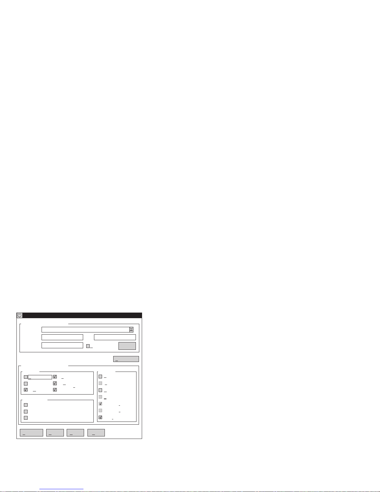
Automatic Dialout Settings: Use the Automatic
Dialout Settings window (shown in Figure 4 on page 60)
to configure the system management subsystem's
automatic dialout functions. If you configure a Dialout
Entry, the system management subsystem will attempt to
forward an alert to a remote Netfinity system, a numeric
pager, or an alphanumeric pager when any of the events
selected from the Enabled Alerts Dialout group occur.
This alert will contain information about the nature of the
event that occurred, the time and date at which the event
occurred, and the name of the system that generated the
alert.
You can configure the Netfinity Advanced System
Management PCI Adapter to dial out to multiple pagers or
Netfinity Manager systems in response to individual critical
and non-critical dialout events. Therefore, the Dialout
status text will read DIALOUT ON as soon as the first
telephone number dialout begins, then change to
DIALOUT OFF when the dialout is completed, then change
to DIALOUT ON again when the second telephone number
is dialed, then change to DIALOUT OFF when the dialout
is completed, and so on. If you click on Stop Dialout, the
Netfinity Advanced System Management PCI Adapter
hangs up, abandons the currently active dialout function,
and moves on to the next one.
Your system management subsystem can be configured
with up to six separate Dialout Entries.
Automatic Dialout Settings - SP NULL modem
Dialout Entry Information
Name : NULL modem
Number : Pin :
Type : Netfinity
Entry Enabled
Delete
Dialout Status : DIAlOUT OFF
Enabled Alerts Dialout
Critical System
Temperature
Voltage
Ta perm
Non-critical
Redundant power supply
Temperature
Single fan failure
Apply/Add
M ltiple fan failureu
Po er failurew
Hard dri ev
Refresh Cancel
Help
Stop dialout
POST timeout
Loader timeout
O/S timeout
Boot failure
Pow er o ff
Pow er on
Appl cationi
Figure 4. The Automatic Dialout Settings window
60 Netfinity Server HMM
Page 69

Dialout Entry Information Group:
a Dialout Entry:
1. In the Name field, type the name of the person or
system to which the alert will be forwarded. The
information in the Name field is strictly for your use in
identifying the Dialout Entry. If you are editing a
previously configured Dialout Entry, select the entry
that you want to edit from the Name selection list.
2. In the Number field, type the telephone number that
will be used by the system's modem to dial out to a
digital pager service. After the modem connects to
the pager service, it will send numeric data specific to
the dialout event.
Note
Depending on your paging service, you might
need to increase the amount of time that this
alert action waits after dialing the telephone
number before it transmits the numeric data. To
increase the amount of time that will pass before
the numeric data is transmitted, add one or more
commas (,) to the end of the telephone number.
Each comma will cause the modem to wait two
seconds before transmitting the numeric data.
3. In the PIN field, type the personal identification
number required by your alphanumeric pager
provider. This field will be active only if you select
Alpha-numeric in the Type field.
4. From the Type selection list, select the type of
connection the system management subsystem will
attempt to make in order to forward the event
notification. You can select Numeric (for standard
pagers), Alpha-numeric (for alphanumeric pagers), or
Netfinity (for connecting to a remote Netfinity system).
5. Check the Entry enabled check box to activate this
Dialout Entry. If the Entry enabled check box is not
checked, no dialouts will be made to this entry.
6. Select dialout events from the Enabled Alerts
Dialout group. If any of the checked events occur,
the system management subsystem will dial out to
the telephone number specified in the Number field
and forward an alert describing the event using the
method selected in the Type field. For more detailed
information about dialout events, see “Enabled Alerts
Dialout Group” on page 62.
7. Click on Apply/Add to save these settings.
To remove a previously configured Dialout Entry, select the
name of the entry from the Name selection list and then
select Delete.
To edit or create
Netfinity 7000-M10 - Type 8680
61
Page 70

Enabled Alerts Dialout Group:
Use the selections
available in the Enabled Alerts Dialout group to specify
which system management subsystem events will result in
all currently configured Dialout Entries being contacted by
the system management subsystem. Any selected items
will, if detected by the system management subsystem,
result in an alert describing the event being forwarded,
using the method selected in the Type field, to the
recipient specified by the Dialout Entry.
If the alert is being forwarded to a pager, Advanced
System Management will include information about the
event that triggered the alert. If the alert is forwarded to a
numeric (or standard), pager, the page will include a code
number that corresponds to the triggering event. If the
alert is forwarded to an alphanumeric pager, the page will
include both a code number and a text string that describe
the triggering event. For more information on the numeric
codes and text strings that are transmitted to pagers, refer
to the following tables.
The Enabled Alerts Dialout group is divided into the
Critical, Non-critical, and System groups. The Critical
Enabled Alerts Dialout group contains the following items.
Item Description (if checked) Numeric
Temperature The system management
Voltage The system management
Tamper The system management
Multiple fan
failure
Power failure The system management
Hard disk drive The system management
subsystem will dial out and
then automatically initiate a
system shutdown if any
monitored temperatures
exceed their threshold
values.
subsystem will dial out if
the voltages of any
monitored power sources
fall outside their specified
operational ranges.
subsystem will add an
entry in the Event Log if six
consecutive remote login
attempts fail.
The system management
subsystem will dial out if
two (or more) of the
system's cooling fans fail
and
will automatically
initiate a system shutdown.
subsystem will dial out if
the system's power supply
fails.
subsystem will dial out if
one or more of the hard
disk drives in the system
fail.
Code
00 Temperature
01 Voltage
02 Tamper
03 Multiple
04 Power
05 Hard
Text
String
Fan
Failure
Failure
Drive
62 Netfinity Server HMM
Page 71

Item Description (if checked) Numeric
Voltage regulator
module failure
The system management
subsystem will dial out and
then automatically initiate a
system shutdown if the
voltage regulator module
(VRM) fails.
Code
06 VRM
Text
String
Failure
The Non-critical Enabled Alerts Dialout group contains the
following items.
Item Description (if checked) Numeric
Temperature The system management
Single
fan
failure
Voltage The system management
subsystem will dial out if
any monitored
temperatures exceed their
threshold values.
However, unlike the Critical
Temperature event, this
Alerts Dialout will
initiate a system shutdown
automatically.
The system management
subsystem will dial out if
one of the system's cooling
fans fail.
subsystem will dial out if
any of the monitored
voltages exceed their
threshold values.
not
Code
12 Non-critical
11 Single Fan Failure
13 Voltage
Text String
Temperature
The System Enabled Alerts Dialout group contains the
following items.
Item Description (if checked) Numeric
POST
timeout
Loader
timeout
O/S
timeout
Power
off
Power
on
The system management
subsystem will dial out if
the POST timeout value
(specified in the System
Management Subsystem
Configuration Settings
window) is exceeded.
The system management
subsystem will dial out if
the Loader timeout value
(specified in the System
Management Subsystem
Configuration Settings
window) is exceeded.
The system management
subsystem will dial out if
the O/S timeout value
(specified in the System
Management Subsystem
Configuration Settings
window) is exceeded.
The system management
subsystem will dial out if
the system is powered off.
The system management
subsystem will dial out if
the system is powered on.
Code
20 POST Hang
26 Loader Watchdog
21 OS Hang
23 System Power Off
24 System Power On
Text String
Failure
Netfinity 7000-M10 - Type 8680 63
Page 72

Item Description (if checked) Numeric
Application The system management
PFA The system management
subsystem will dial out if it
receives a Netfinity alert
(Netfinity can forward alerts
directly to the system
management subsystem
using the Alert Manager
Forward Alert to System
Management Subsystem
action).
subsystem will dial out if it
receives a Predictive
Failure Analysis (PFA) alert
from the system.
Code
22 Application Logged
27 PFA
Text String
Event
Event Log: Use Event Log to open the System
Management Subsystem Logs window (shown in
Figure 5). This window contains all entries that are
currently stored in the system management subsystem
event log. Information about all remote access attempts
and dialout events that have occurred is recorded in the
system management subsystem event log.
System Power Control - SP NULL modem
08-19-97 10:24:35a SERVPROC Remote logon. User ID : BOB
08-18-97 05:03:05p SERVPROC Remote logon. User ID : BOB
08-18-97 04:07:00p SERVPROC System complex reset. Source: Remote request
08-18-97 04:04:34p SERVPROC Remote logon. User ID : BOB
08-17-97 01:17:28p SERVPROC System complex reset. Source: Remote request
08-17-97 01:16:18p SERVPROC Remote logon. User ID : BOB
08-17-97 01:11:27p SERVPROC Modem configured but not responding.
08-14-97 11:06:09a SERVPROC Modem configured but not responding.
08-14-97 11:06:01a NETFIN Ap: _0000 T:UNKUNK S:3 hello2 System:LYNX
08-14-97 11:03:09a SERVPROC Remote logon. User ID : BOB
08-19-97 10:29:25a SERVPROC Remote logon. User ID : BOB
08-19-97 10:28:44a SERVPROC Event log cleared.
Event Log
Refresh C ear Logl
Cancel
Help
Figure 5. The System Management Subsystem Logs
window
64 Netfinity Server HMM
Page 73

Notes
1. If you are using the Advanced System
Management service with an Netfinity Advanced
System Management PCI Adapter installed in a
Netfinity 7000 server, the event log might contain
entries that begin with the text “I2C Message.”
These messages are normal and are intended for
use by IBM servicers in the event of system
problems.
2. If you are using the Advanced System
Management service with a Netfinity 7000 server,
the event log will also include any POST error
messages.
The following functions are available from the Options
pulldown menu in the System Management Subsystem
Logs window:
Load
Refreshes the contents of the System Management
Subsystem Logs window.
Print to File
Saves the contents of the System Management
Subsystem Logs window to a text file.
Print to Printer
Sends the contents of the System Management
Subsystem Logs window to a printer attached to your
system.
Clear Log
Erases all entries that are currently stored in the
system management subsystem Event Log (including
any entries that are not currently visible in the System
Management Subsystem Log window).
Note
Once you use Clear Log to erase the entries in
the system management subsystem Event Log,
they are permanently erased and cannot be
retrieved.
Operational Parameters: The Operational
Parameters window (see Figure 6 on page 66) shows the
current values or status of many system components
monitored by the system management subsystem.
Available values include:
Power supply voltages (including +5 V ac, +12 V ac,
-3.3 V ac, -12 V ac; Netfinity 7000 servers feature
additional -5 V ac and Voltage Regulation Module
[VRM] monitors).
Current temperatures and threshold levels for system
components such as far-end adapter, center adapter,
microprocessors, I/O board, and DASD backplane.
Netfinity 7000-M10 - Type 8680
65
Page 74

Note
Monitored system components vary by system
management subsystem.
System state (including O/S started, O/S running,
POST started, POST stopped (error detected), and
system powered off/state unknown).
System power status (on or off).
Power on hours; the total number of hours that the
system has been powered on. (This is a cumulative
count of all powered-on hours, not a count of hours
since the last system restart).
Figure 6. The Operational Parameters window
System Power Control: Use the System Power
Control window to instruct the system management
subsystem to power off the system, restart the system, or
power on the system. To initiate any of the power control
options, you must first check the Enable power control
options check box. If this check box is unchecked, the
Power Control Options field will not be available.
System Power Control - SP NULL modem
Enable power control options
Power Control Options
Power off with O/S shutdown.
Pow er off now.
Pow er on now.
Restart the system with O/s shutdown.
Restar t the sy stem now.
Apply
Cancel
Figure 7. The System Power Control window
The following System Power Control functions are
available at all times.
66 Netfinity Server HMM
Help
Page 75

Function Description
Power off with O/S
shutdown
Power off now Immediately removes power from the
Restart the system with O/S
shutdown
Restart the system now Immediately removes and then restores
Performs an O/S shutdown before
removing power from the system.
system.
Performs an O/S shutdown, removes
power from the system, and then restores
power to the system.
power to the system.
If you are connected to the system management
subsystem through a modem, the Power on now selection
will also be available. This function powers up the system
and allows the microprocessor to perform POST, loading,
and O/S startup procedures.
To initiate a Power Control Option:
1. Check the Enable power control options check box.
Note
To initiate any of the power control options, you
must first check the Enable power control
options check box. If this check box is
unchecked, the Power Control Options field will
not be available.
2. From the Power Control Options field, select the
Power Control Option you want to activate.
3. Click on Apply.
Remote POST Console: You can use the
Advanced System Management Remote POST Console
function to remotely monitor, record, and replay all textual
output generated during POST. To monitor and record the
POST data on a remote system:
1. Connect to the remote system's system management
subsystem.
2. Open the Remote POST window.
3. Restart the remote system (using the Advanced
System Management's System Power Control
functions).
All POST data will be displayed in and recorded by the
Remote POST Console as the remote system completes
POST. While you are monitoring POST on a remote
system, all local keystrokes are relayed automatically to
the remote system, enabling you to interact with the POST
process on the remote system.
To review data after POST completes, disconnect from the
remote system and use the Replay functions.
Netfinity 7000-M10 - Type 8680 67
Page 76

POST has started
RHeplay elp
IBM SurePath BIOS - © Copyright IBM Corporation 1997
SMP system with 1 processor(s) : BPS is P1 and no AP present...
Pentium Pro 180 MHz
Ô
Press F1 for Configuration/Setup
>> Build ID - RAET39AUS, BIOS Revision 7 <<
~~~~ ~~
~~~~ ~~
~~~~ ~~
Figure 8. The Remote POST window
Use the selections available in the Replay pull-down menu
to replay the textual output that was captured during the
last Remote POST operation. All text that was displayed
by the remote system during POST will be displayed as it
appeared on the remote system.
To begin playing the recorded POST data, or to
resume playing the recorded POST data after
stopping playback, click on Replay Last POST.
To halt playback of the recorded POST data, click on
Stop.
To resume viewing the recorded POST data from the
beginning, click on Restart.
Select Fast, Medium, or Slow to specify the speed at
which the recorded POST data is displayed in the
Remote POST window.
Note
Remote POST data can be replayed only when you
not
connected to a remote system's system
are
management subsystem.
Updating System Management Subsystem
Microcode: To update the system management
subsystem microcode:
1. From the Options pulldown menu, select Update
Microcode... and then select System Management
Subsystem.
A file selection window appears.
2. Use the file selection window to select the source disk
drive (or diskette drive) and directory where the
system management subsystem microcode update is
located.
3. Select OK to continue.
4. Warning notices will appear, asking that you verify
that you want to continue. Select OK to continue or
Cancel to stop the microcode update process.
68 Netfinity Server HMM
Page 77

5. When you have verified that you want to proceed with
updating the system management subsystem
microcode, the Advanced System Management
service will apply the microcode update to the system
management subsystem.
During this process, some of the monitoring functions
of some system management subsystems (such as
the environmental monitors available with the Netfinity
7000 Netfinity Advanced System Management PCI
Adapter) will be disabled. Once the microcode
update is complete, all system monitoring will resume.
Accessing the Advanced System
Management Adapter II without Netfinity
Manager: If you are unable to use Netfinity Manager
to access and manage your Netfinity Advanced System
Management PCI Adapter, you can use a terminal program
and a modem to connect directly to the Netfinity Advanced
System Management PCI Adapter. This modem should be
connected to serial port A or management port C to use
the remote functions. (Refer to your server
Handbook
management port C. For more information on configuring
the Netfinity Advanced System Management PCI Adapter
modem, see “Modem Settings” on page 54.)
Also, if the Netfinity Advanced System Management PCI
Adapter is attached to and configured to use a TCPIP
network (using the Ethernet port), you can use a TELNET
session or web browser to connect to the Netfinity
Advanced System Management PCI Adapter.
When connected, you will be able to access a variety of
monitor, configuration, and error log data. You can also:
Power the remote system on or off
Shut down and restart the server
Initiate remote video mode on the system
for information on serial port A and
management subsystem
Remote video mode enables you to remotely monitor
all textual output generated during POST. All POST
data will be displayed in the terminal program window
as the remote system completes POST. While you
are monitoring POST on the remote system, all local
keystrokes are relayed automatically to the remote
system, enabling you to use POST utilities (such as
system configuration, redundant array of independent
disks [RAID] mini-configuration program, and
diagnostic programs) that can be accessed during
POST.
User's
Netfinity 7000-M10 - Type 8680
69
Page 78

Establishing a Direct Connection to the
Netfinity Advanced System Management
PCI Adapte: You can establish a direct connection to
the Netfinity Advanced System Management PCI Adapter
in one of three ways:
Connect using a serial connection and a terminal
program
Connect using a TCPIP network connection and a
TELNET session
Connect using a TCPIP network connection and a
web browser
Using a Terminal Program to Connect:
terminal program to establish a connection with the
system management subsystem:
1. Use a terminal program to establish a connection with
the system management subsystem modem.
Use the following modem settings:
Baud 57.6 k
Data Bits 8
Parity None
Stop Bits 1
Flow Control Hardware
2. Dial the Netfinity Advanced System Management PCI
Adapte.
3. Log in to the system management subsystem.
When you have established a connection with the
system management subsystem, you will be
prompted for a username and password. You must
provide a username and password combination that
has been previously configured for use with the
system management subsystem.
You can use one of two username and password
combinations:
The default username (USERID) and password
(PASSW0RD)
Note
The default username and password are
case sensitive. You must use all caps, and
the “0” in PASSW0RD is the numeral zero.
To use a
A username and password that you define using
the Advanced System Management service and
Netfinity Manager
70 Netfinity Server HMM
Page 79

Important
For security purposes, change the username and
password using the Advanced System
Management service. For more information, see
“Configuration Settings” on page 50.
If you update the system management
subsystem microcode, the default username
(USERID) and password (PASSW0RD) are reset.
If you had previously changed them, you will
need to change them again.
When you have logged in, you will be presented with the
Netfinity Advanced System Management PCI Adapter
menu system. For more information, see “Netfinity
Advanced System Management PCI Adapter Menus” on
page 73
Using a TELNET Session to Connect:
TELNET session to establish a connection with the
system management subsystem:
1. TELNET to the TCPIP address that has been
assigned to the Netfinity Advanced System
Management PCI Adapter.
2. Log in to the system management subsystem.
When you have established a connection with the
system management subsystem, you will be
prompted for a username and password. You must
provide a username and password combination that
has been previously configured for use with the
system management subsystem.
You can use one of two username and password
combinations:
The default username (USERID) and password
(PASSW0RD)
Note
The default username and password are
case sensitive. You must use all caps, and
the “0” in PASSW0RD is the numeral zero.
A username and password that you define using
the Advanced System Management service and
Netfinity Manager
To use a
Netfinity 7000-M10 - Type 8680
71
Page 80

Important
For security purposes, change the username and
password using the Advanced System
Management service. For more information, see
“Configuration Settings” on page 50.
If you update the system management
subsystem microcode, the default username
(USERID) and password (PASSW0RD) are reset.
If you had previously changed them, you will
need to change them again.
When you have logged in, you will be presented with the
Netfinity Advanced System Management PCI Adapter
menu system. For more information, see “Netfinity
Advanced System Management PCI Adapter Menus” on
page 73
Using a Web Browser to Connect:
browser to establish a connection with the system
management subsystem:
1. Type in the location or URL address field of your web
broswer the TCPIP address that has been assigned
to the Netfinity Advanced System Management PCI
Adapter.
2. Log in to the system management subsystem.
When you have established a connection with the
system management subsystem, you will be
prompted for a username and password. You must
provide a username and password combination that
has been previously configured for use with the
system management subsystem.
You can use one of two username and password
combinations:
The default username (USERID) and password
(PASSW0RD)
Note
The default username and password are
case sensitive. You must use all caps, and
the “0” in PASSW0RD is the numeral zero.
A username and password that you define using
the Advanced System Management service and
Netfinity Manager
To use a web
72 Netfinity Server HMM
Page 81

Important
For security purposes, change the username and
password using the Advanced System
Management service. For more information, see
“Configuration Settings” on page 50.
If you update the system management
subsystem microcode, the default username
(USERID) and password (PASSW0RD) are reset.
If you had previously changed them, you will
need to change them again.
When you have logged in, you will be presented with the
Netfinity Advanced System Management PCI Adapter
menu system. For more information, see “Netfinity
Advanced System Management PCI Adapter Menus”
Netfinity Advanced System Management
PCI Adapter Menus: When you have logged into
the system management subsystem, the following main
menu appears:
2 Monitors
3 Error Logs
4 System Management Adapter Configuration
5 System Services
6 System Power
7 Boot
B Remote Terminal Status
Y Disconnect Current Logon
Z Start Remote Video
To access a menu item, press the number or letter that
corresponds to the information that you want to access (or,
if you are using a web browser to access the Netfinity
Advanced System Management PCI Adapter, click on the
menu selection that corresponds to the information that
you want to access). After you select a menu item,
subsequent menus will offer more specific information that
pertains to the selection you made from the main menu.
To return to the main menu, press the Esc key.
Note
Selecting Y Disconnect Current Logon ends
the current session and requires you to enter a
new username and password before continuing.
Selecting Read displays the last entry.
Selecting Read Last steps backwards through
the entries.
Selecting Write executes the command.
Netfinity 7000-M10 - Type 8680 73
Page 82

Menu Selection Data Available for Viewing
Monitors I/O board temperature, CPU
Error Logs Contents of system error log
System Management
Adapter Configuration
System Services Status of system management
System Power Current system power status,
temperatures, voltage readings,
voltage regulator module readings, fan
status
System management subsystem
modem configuration, dial-out entries,
dial-out alerts, dial-in logins, system
status, thresholds, system statistics,
vital product data (VPD) information,
and system state
subsystem watchdog timers and event
alerts sent to the host system.
power-off configuration, and power-off
delay values.
Note
You can use selections available
from the System Power menu
to power the system on or off.
For more information, see
“System Power Menu
Selections” on page 74.
Boot You can use selections available from
Remote Terminal Status Current remote terminal status
Start Remote Video Use Start Remote Video to enable
the Boot menu to shutdown and
restart your system or to restart the
system management subsystem. For
more information, see “Boot Menu
Selections” on page 76.
your terminal program to remotely
monitor and manage the server during
POST. For more information, see
“Using Remote Video Mode to Monitor
and Access POST” on page 77.
When you are finished accessing the system management
subsystem using a terminal program, select Disconnect
Current Logon from the main menu and then use your
terminal program to close the connection to the system
management subsystem.
System Power Menu Selections: You can use
the selections available from the System Power menu to:
View data regarding the current server power status
View data regarding the server power configuration
Power the server off
Power the server on
To access these functions:
1. Use a terminal program, TELNET session, or web
browser to establish a connection with the system
management subsystem modem.
2. Log in to the system management subsystem.
When you have established a connection with the
system management subsystem, you will be
74 Netfinity Server HMM
Page 83

prompted for a username and password. You must
provide a username and password combination that
has been previously configured for use with the
system management subsystem. You can use one of
two username and password combinations:
The default username (USERID) and password
(PASSW0RD)
Note
The default username and password are
case sensitive. You must use all caps, and
the “0” in PASSW0RD, is the numeral zero.
A username and password that you define using
the Advanced System Management service and
Netfinity Manager
Important
For security purposes, change the username and
password using the Advanced System
Management service. For more information see
“Configuration Settings” on page 50.
If you update the system management
subsystem microcode, the default username
(USERID) and password (PASSW0RD) are reset.
If you had previously changed them, you will
need to change them again.
When you have logged into the system management
subsystem, the following main menu appears:
2 Monitors
3 Error Logs
4 System Management Adapter Configuration
5 System Services
6 System Power
7 Boot
B Remote Terminal Status
Y Disconnect Current Logon
Z Start Remote Video
3. Select 6 System Power.
The following System Power menu appears:
1 Current Power Status
2 Power Configuration
3 Power On
4 Power Off
4. Select a System Power menu item.
Select 1 Current power Status for information
about the current server power status.
Select 2 Power Configuration for information
about the server power configuration.
Select 3 Power On to power the server on (if it
is currently powered off).
Select 4 Power Off to power the server off (if it
is currently powered on).
Netfinity 7000-M10 - Type 8680
75
Page 84

Boot Menu Selections: You can use the
selections available from the Boot menu to:
Shut down the server operating system and then
restart the server
Restart the server immediately, without first
performing an operating system shutdown
Restart the system management subsystem
To access these functions:
1. Use a terminal program, TELNET session, or web
browser to establish a connection with the system
management subsystem modem.
2. Log in to the system management subsystem.
When you have established a connection with the
system management subsystem, you will be
prompted for a username and password. You must
provide a username and password combination that
has been previously configured for use with the
system management subsystem. You can use one of
two username and password combinations:
The default username (USERID) and password
(PASSW0RD)
note
The default username and password are
case sensitive. You must use all caps, and
the “0” in PASSW0RD, is the numeral zero.
A username and password that you define using
the Advanced System Management service and
Netfinity Manager
Important
For security purposes, change the username and
password using the Advanced System
Management service. For more information see
“Configuration Settings” on page 50.
If you update the system management
subsystem microcode, the default username
(USERID) and password (PASSW0RD) are reset.
If you had previously changed them, you will
need to change them again.
When you have logged into the system management
subsystem, the following main menu appears:
2 Monitors
3 Error Logs
4 System Management Adapter Configuration
5 System Services
6 System Power
7 Boot
B Remote Terminal Status
Y Disconnect Current Logon
Z Start Remote Video
76 Netfinity Server HMM
Page 85

3. Select 7 Boot.
The following Boot menu appears:
1 Reboot w/OS Shutdown
2 Reboot immediately
3 Restart SP
4. Select a Boot menu item.
Select 1 Reboot w/OS Shutdown to shutdown
the server operating system and then restart the
server.
Select 2 Reboot immediately to restart the
server immediately, without first shutting down
the operating system.
Select 3 Restart SP to restart the system
management subsystem.
Using Remote Video Mode to Monitor and
Access POST: You can use a terminal program,
TELNET session, or web browser to remotely monitor all
textual output generated during POST. All POST data will
be displayed in the terminal program window as the
remote system completes POST. While you are
monitoring POST on the remote system, all local
keystrokes are relayed automatically to the remote system,
enabling you to use POST utilities (such as system
configuration, RAID mini-configuration program, or
diagnostic programs) that can be accessed during POST.
To use Remote Video Mode to monitor and access POST
on the server:
1. Use a terminal program, TELNET session, or web
browser to establish a connection with the system
management subsystem modem.
2. Log in to the system management subsystem.
When you have established a connection with the
system management subsystem, you will be
prompted for a username and password. You must
provide a username and password combination that
has been previously configured for use with the
system management subsystem. You can use one of
two username and password combinations:
The default username (USERID) and password
(PASSW0RD)
Note
The default username and password are
case sensitive. You must use all caps, and
the “0” in PASSW0RD, is the numeral zero.
A username and password that you define using
the Advanced System Management service and
Netfinity Manager
Netfinity 7000-M10 - Type 8680 77
Page 86

Important
For security purposes, change the username and
password using the Advanced System
Management service. For more information, see
“Configuration Settings” on page 50.
If you update the system management
subsystem microcode, the default username
(USERID) and password (PASSW0RD) are reset.
If you had previously changed them, you will
need to change them again.
When you have logged into the system management
subsystem, the following main menu appears:
2 Monitors
3 Error Logs
4 System Management Adapter Configuration
5 System Services
6 System Power
7 Boot
B Remote Terminal Status
Y Disconnect Current Logon
Z Start Remote Video
3. Start (or restart) the server.
If the remote server is currently powered off:
a. Select 6 System Power from the main
menu.
b. Select 4 Power On from the System Power
menu.
If the server is currently powered on, you must
restart the server. You can use selections from
the System Power menu or the Boot menu to
restart the server in several ways.
To restart the server using System Power menu
selection:
a. Select 6 System Power from the main
menu.
b. Select 3 Power Off from the System Power
menu.
c. Once the server has powered off, select 4
Power On to restore power to the server.
To restart the server using Boot menu
selections:
a. Select 7 Boot from the main menu.
b. Select either 1 Reboot w/OS Shutdown or
2 Reboot Immediately to restart the
server.
Note
For information on the System Power and
Boot menus, see “System Power Menu
Selections” on page 74 and “Boot Menu
Selections” on page 76.
78 Netfinity Server HMM
Page 87

4. After you restart the server, return to the main menu
and select Z Start Remote Video.
Once you have started Remote Video mode on the system
management subsystem, all textual output generated
during POST will be sent to your terminal window or
TELNET session. Your terminal or TELNET session will
also act as a fully-active remote session, enabling you to
enter keyboard commands that will be sent to the remote
server. In this way, you can enter key commands and
key-combinations that access POST operations and
utilities, such as system setup or the RAID
mini-configuration program.
When you have finished using Remote Video mode, press
Ctrl+R, then press Ctrl+E, and then press Ctrl+T. This
will end Remote Video mode and return you to the main
menu.
Netfinity 7000-M10 - Type 8680 79
Page 88

Netfinity Advanced System
Management Token Ring Connection
Option
The Netfinity Advanced System Management Token Ring
Connection includes an IBM Turbo 16/4 Token Ring PC
Card that you install in the PCMCIA slot on the Advanced
System Management PCI Adapter. The option also
includes a PC Card to 9-pin D-shell cable that you first
connect to the PC card and then route through the rear
chassis cut-out on the server. Finally, the option includes
a complete copy of Netfinity Manager version 5.20.2. The
licensed version of Netfinity Manager, shipped with the
option replaces the licensed version of Netfinity Manager
that comes with ServerGuide (included with the Netfinity
server). The version of Netfinity Manager, shipped with
the option, includes advanced features that enable you to
configure and control the Advanced System Management
PCI Adapter.
Attention
After you have installed the Netfinity Advanced
System Management Token Ring Connection, you
must not enable or use the Ethernet port that is
included on the Advanced System Management PCI
Adapter. Enabling the Ethernet port while the IBM
Turbo 16/4 Token Ring PCMCIA card is installed on
the adapter will cause the system to become unstable.
To enable, configure, or use the Ethernet port, you
must first remove the IBM Turbo 16/4 Token Ring
PCMCIA card from the Advanced System
Management PCI Adapter.
The option ships with the following components:
IBM Turbo 16/4 Token Ring PC Card
Token Ring Cable
Safety Information Booklet
Netfinity Manager CD-ROM
Installation Instructions
Attention
Before proceeding, read the safety information
included with the option.
To install the Netfinity Advanced System Management
Token Ring Connection, do the following:
1. Use the Netfinity Manager Advanced System
Manager service to disable the Ethernet network
interface (if it is enabled).
This step is necessary only if you have used the
Advanced System Management service previously to
80 Netfinity Server HMM
Page 89

enable the Ethernet network interface on the
Advanced System Management PCI Adapter. For
information on how to enable or disable network
interfaces on the adapter, see the
Management
section of the Server Library that was
Advanced System
included with the server.
2. Shut down and power off the server.
3. Disconnect the server power cord from the wall
socket.
4. Remove the server cover.
5. Locate and remove the Advanced System
Management PCI Adapter.
To remove the Advanced System Management PCI
Adapter from the server:
a. Unplug all connections from the back of the
adapter.
b. Carefully move aside any cables (such as DASD
cables or power cables) that block access to the
Advanced System Management PCI Adapter.
c. Disconnect the power cable from the top of the
Advanced System Management PCI Adapter.
d. Carefully remove the adapter from the server.
6. Install the PCMCIA card .2/ into the PCMCIA slot on
the adapter .1/ as shown in the following figure.
7. Connect one end of the token ring cable .2/ to the
PCMCIA connector on the PCMCIA card .1/ as
shown in the following figure.
Netfinity 7000-M10 - Type 8680 81
Page 90

8. Lock the PCMCIA connector by pushing the slide .4/
forward as shown.
9. Locate and remove the external connector knockout
on the back panel of the server.
To remove the external connector knockout, use a flat
blade screwdriver to carefully tap the bottom edge of
the knockout panel. The knockout will bend toward
the interior of the server. After the external connector
knockout has bent in slightly, insert the tip of the
screwdriver between the edge of the knockout and
the back panel of the server and gently pry the
knockout off.
Attention
Be careful not to bend the back panel of the
server while removing the knockout.
10. Reinstall the Advanced System Management PCI
Adapter. Be sure to reconnect any cables that you
disconnected when removing the adapter from the
server.
11. Insert the end of the token ring cable .3/ into the
external connector opening and secure it in place with
the included screws.
12. Replace the server cover and reconnect the server to
a power source.
System Reliability Considerations
To help ensure proper cooling and system reliability, make
sure:
Each of the drive bays has either a drive or a filler
panel installed.
82 Netfinity Server HMM
Page 91

Each of the power supply bays has either a power
supply or a filler panel installed.
The top cover is in place during normal operation.
The front access cover is in place during normal
operation.
There is at least 305 mm (12 inches) of ventilation
space at the front and rear of the server.
The Power switch on the power supply is off before
you remove a functional power supply.
Cables for optional adapters are routed according to
the instructions provided with the adapters.
A fan that has failed is replaced as soon as
convenient to help maintain the redundant cooling
capability.
Netfinity 7000-M10 - Type 8680 83
Page 92

Specifications
The following table contains the specifications for the
Netfinity 7000 M10.
Size
Depth: 650 mm (25.6 in.)
Height: 489 mm (19.25 in.) (11 U)
Width: 440 mm (17.3 in.)
Weight
Unpacked, minimum configuration:
39 kg (85 lb.)
Unpacked, maximum configuration:
70.31 kg (155 lb.)
Electrical Input
Sine-wave input (50± or 60± Hz)
is required
Input voltage
– Low range
- Minimum: 90 V ac
- Maximum: 137 V ac
– High range
- Minimum: 180 V ac
- Maximum: 265 V ac
– Input kilovolt-amperes (KVA) approximately
- Minimum configuration as shipped: 0.2
KVA
- Maximum configuration: 0.78 KVA
Environment
Air temperature
– System on: 10° to 35° C
(50° to 95° F)
Altitude: 0 to 914 m (3000 ft.)
– System on: 10° to 32° C
(50° to 89.6° F)
Altitude: 914 m (3000 ft.) to 2133 m (7000 ft.)
– System off: 10° to 43° C
(50° to 110° F)
Maximum altitude: 2133 m (7000 ft.)
Humidity
– System on:
8% to 80%; maximum wetbulb
23° C (73.4° F)
– System off:
8% to 80%; maximum wetbulb 27° C (80.6° F)
Altitude: 0 to 2133 m (0 to 7000 ft.)
Electrostatic Discharge
Tested to 20 KV
84 Netfinity Server HMM
Page 93

Immunity
Verified to comply with
EN 50082-2
Acoustical Noise Emissions Values
Declared (upper limit) sound power levels:
– 6.5 bels operating
– 6.5 bels idle
These levels are measured in controlled acoustical
environments according to the American National
Standards Institute (ANSI) procedure S12.10 and ISO
7779, and are reported in accordance with ISO 9296. The
declared sound power levels indicate an upper limit, below
which a large portion of machines operate.
Heat Output
Approximate heat output in
British thermal units (Btu) per hour:
– Minimum configuration: 1024 Btu
– Maximum configuration: 2662 Btu
Safety Standards
UL 1950
CSA C22.2 No. 950-M93
EN 60950 and countries deviations
IEC 950
NOM-019
Netfinity 7000-M10 - Type 8680
85
Page 94

Locations
The following information supports the Netfinity 7000-M10 Type 8680 server.
“AC Power Assembly Removal” on page 87.
“Advanced System Management PCI Adapter
Component Locations” on page 88.
“Battery” on page 89.
“Changing Jumper Positions” on page 93.
“Completing the Installation” on page 97.
“Connecting External Options” on page 100.
“Controls and Indicators” on page 109.
“Hot-Swap Fan Assembly” on page 112.
“Hot-Swap Power Supplies” on page 114.
“Hot-Swap Power Supply Installation” on page 115.
“Hot-Swap Power Supply Removal” on page 118.
“Information LED Panel” on page 120.
“Input/Output Connectors and Expansion Slots” on
page 121.
“Installing and Removing the Server from a Rack” on
page 124.
“Internal Drives Installation” on page 136.
“I/O Board Component Locations” on page 142.
“I/O Board LEDs” on page 143.
“I/O Board Removal” on page 144.
“I/O Function Card Component Locations” on
page 145.
“I/O Function Card Jumpers” on page 146.
“Memory Board Component Locations” on page 147.
“Memory-Module Kits Installation” on page 148.
“Microprocessor Kit Installation” on page 153.
“Power Backplane Connector Locations” on
page 157.
“Power Backplane Removal” on page 158.
“Power Control Card Removal” on page 159.
“Preparing to Install Options” on page 160.
“Processor Board Component Locations” on
page 165.
“Processor Board Jumpers” on page 166.
“Processor Board Assembly Removal” on page 167.
“Quarter-Turn Fastener” on page 168.
“SCSI Backplane Component Locations” on
page 168.
“Shuttle Assembly Removal” on page 169.
“Working Inside a Server with Power On” on
page 171.
“Working with Adapters” on page 173.
86 Netfinity Server HMM
Page 95

AC Power Assembly Removal
Before you begin:
Read “Safety Information” on page 226.
The AC power assembly is located in the rear of the
system.
To remove the AC power assembly, do the following:
1. Power-off the system.
2. Disconnect all power to the system.
3. Remove the power AC power assembly screws .1/
4. Pull the AC power assembly .2/ out of the the
system.
Netfinity 7000-M10 - Type 8680
87
Page 96

Advanced System Management PCI
Adapter Component Locations
The following simplified layout of the Advanced Remote
Management Controller identifies the components.
.1/ 10/100 Ethernet port connector
.2/ Dual serial port connector
.3/ RS 485 bus connector
.4/ External power supply connector
.5/ PCMCIA token ring connector
.6/ Power on LED (CR2 bottom)
.7/ Processor error LED (CR2 top)
.8/ Ethernet activity LED (CR3 bottom)
.9/ Ethernet link LED (CR3 top)
.1ð/ I/O function card connector
.11/ Reserved J9
88 Netfinity Server HMM
Page 97

Battery
IBM has designed this product with your safety in mind.
The lithium battery must be handled correctly to avoid
possible danger. If you replace the battery, you must
adhere to the following instructions.
Caution
When replacing the battery, use only IBM Part
Number 33F8354 or an equivalent type battery
recommended by the manufacturer. If your system
has a module containing a lithium battery, replace it
only with the same module type made by the same
manufacturer. The battery contains lithium and can
explode if not properly used, handled, or disposed of.
Do not:
Throw or immerse into water
Heat to more than 100°C (212°F)
Repair or disassemble
Dispose of the battery as required by local ordinances
or regulations.
Before you begin, be sure you have:
Read “Safety Information” on page 226.
Followed any special handling and installation
instructions supplied with the replacement
battery.
Note
After you replace the battery, you must reconfigure
your server and reset the system date and time.
Netfinity 7000-M10 - Type 8680 89
Page 98

To replace the battery:
1. Turn off the server and peripheral devices and
disconnect all external cables and power cords (see
“Preparing to Install Options” on page 160); then
remove the top cover (see “Removing the Top Cover”
on page 161).
2. Remove the I/O function card from the server:
a. Refer to the following illustration while you
perform the steps in this procedure.
b. Disconnect the cables .1/ from the I/O function
card .2/. Note carefully where each cable is
connected before you remove it.
c. Remove the two screws .2/ located on the metal
connector plate inside the server.
d. Carefully grasp the I/O function card by its top
edge and pull the I/O function card out of the
server.
e. Place the I/O function card connector-side up on
a flat, static-protective surface.
3. Locate the battery on the I/O function card (see “I/O
Function Card Component Locations” on page 145).
90 Netfinity Server HMM
Page 99

4. Remove the battery:
a. Use one finger to lift the battery clip over the
battery.
b. Use one finger to slightly slide the battery toward
the rear of the I/O function card. The spring
mechanism behind the battery will push it out
toward you as you slide it forward.
c. Use your thumb and index finger to pull the
battery from under the battery clip.
d. Ensure that the battery clip is touching the base
of the battery socket by pressing gently on the
clip.
5. Insert the new battery:
a. Tilt the battery so that you can insert it into the
front of the socket, under the battery clip.
b. As you slide it under the battery clip, press the
battery down into the socket.
6. Install the I/O function card:
a. Carefully grasp the I/O function card by its top
edge, and insert the tabs .3/ on the bottom
edge of the metal connector plate in the
matching openings on the server back panel.
b. Align the I/O function card with the guide on the
opposite end of the adapter and the slot on the
I/O board.
c. Press the I/O function card
firmly
into the slot.
Attention: When you install the I/O function
card in the server, be sure that it is completely
and correctly seated. Incomplete insertion might
cause damage to server components.
d. Insert the two screws you removed in step 2c on
page 90.
e. Connect the cables you disconnected in step 2b
on page 90.
Netfinity 7000-M10 - Type 8680
91
Page 100

7. Reinstall the top cover and complete the installation
(see “Completing the Installation” on page 97).
8. Start the Configuration/Setup Utility program and
reset configuration parameters as needed.
To reset the system date and time, go to “Date
and Time” on page 28.
To reset the power-on password, go to “Using
the Power-On Password Menu” on page 29.
To reconfigure your server, follow the
instructions given in “The Configuration/Setup
Utility Program” on page 25 (all models).
92 Netfinity Server HMM
 Loading...