

Page 1

xSeries 345 Ty pe 8670
Hardw are Maintenance Manual and
Troubleshooting Guide
Page 2

Page 3

xSeries 345 Ty pe 8670
Hardw are Maintenance Manual and
Troubleshooting Guide
Page 4

13th Edition (May 2007)
The most recent version of this document is available on the World Wide Web at http://www.ibm.com/support.
© Copyright International Business Machines Corporation 2004. All rights reserved.
US Government Users Restricted Rights – Use, duplication or disclosure restricted by GSA ADP Schedule Contract
with IBM Corp.
Page 5

Contents
Chapter 1. General information . . . . . . . . . . . . . . . . . . .1
Related publications . . . . . . . . . . . . . . . . . . . . . . .1
Notices and statements in this book . . . . . . . . . . . . . . . . .2
Features and specifications . . . . . . . . . . . . . . . . . . . . .3
Server controls and indicators . . . . . . . . . . . . . . . . . . . .4
Front view . . . . . . . . . . . . . . . . . . . . . . . . . .4
Rear view . . . . . . . . . . . . . . . . . . . . . . . . . .5
Server power features . . . . . . . . . . . . . . . . . . . . . . .6
Turning on the server . . . . . . . . . . . . . . . . . . . . . .6
Turning off the server . . . . . . . . . . . . . . . . . . . . . .6
Standby mode . . . . . . . . . . . . . . . . . . . . . . . .7
Chapter 2. Configuring your server . . . . . . . . . . . . . . . . .9
Using the ServerGuide Setup and Installation CD . . . . . . . . . . . .9
System partition . . . . . . . . . . . . . . . . . . . . . . .10
Typical NOS installation . . . . . . . . . . . . . . . . . . . .10
Setting up or updating multiple servers . . . . . . . . . . . . . . .11
Installing your NOS without ServerGuide . . . . . . . . . . . . . .11
Using the Configuration/Setup Utility program . . . . . . . . . . . . . .11
Starting the Configuration/Setup Utility program . . . . . . . . . . . .11
Using passwords . . . . . . . . . . . . . . . . . . . . . . .12
Using ServeRAID Manager . . . . . . . . . . . . . . . . . . . .13
Configuring the controller . . . . . . . . . . . . . . . . . . . .14
Viewing your configuration . . . . . . . . . . . . . . . . . . . .17
Getting assistance . . . . . . . . . . . . . . . . . . . . . .19
Using the LSI Logic Configuration Utility program . . . . . . . . . . . .20
Updating the integrated system-management firmware . . . . . . . . . .21
Configuring the Ethernet controller . . . . . . . . . . . . . . . . . .21
Teaming mode . . . . . . . . . . . . . . . . . . . . . . . .22
Priority packet mode . . . . . . . . . . . . . . . . . . . . . .22
Virtual LAN mode . . . . . . . . . . . . . . . . . . . . . . .24
Chapter 3. Diagnostics . . . . . . . . . . . . . . . . . . . . .25
General checkout . . . . . . . . . . . . . . . . . . . . . . . .25
Diagnostic tools overview . . . . . . . . . . . . . . . . . . . . .26
POST error logs . . . . . . . . . . . . . . . . . . . . . . . .27
Viewing error logs from the Configuration/Setup Utility program . . . . . .27
Viewing error logs from diagnostic programs . . . . . . . . . . . . .28
ServerGuide error symptoms . . . . . . . . . . . . . . . . . . . .28
Small computer system interface messages . . . . . . . . . . . . . .28
Diagnostic programs and error messages . . . . . . . . . . . . . . .28
Text messages . . . . . . . . . . . . . . . . . . . . . . . .29
Starting the diagnostic programs . . . . . . . . . . . . . . . . .30
Diagnostic error message tables . . . . . . . . . . . . . . . . .31
Identifying problems using status LEDs . . . . . . . . . . . . . . . .31
Power supply LEDs . . . . . . . . . . . . . . . . . . . . . .31
Light Path Diagnostics . . . . . . . . . . . . . . . . . . . . .32
Recovering the BIOS code . . . . . . . . . . . . . . . . . . . .36
Power checkout . . . . . . . . . . . . . . . . . . . . . . . .37
Troubleshooting the Ethernet controller . . . . . . . . . . . . . . . .38
Network connection problems . . . . . . . . . . . . . . . . . .38
Ethernet controller troubleshooting chart . . . . . . . . . . . . . .39
Ethernet controller messages . . . . . . . . . . . . . . . . . .40
© Copyright IBM Corp. 2004 iii
Page 6

Chapter 4. Customer replaceable units . . . . . . . . . . . . . . .41
Before you begin . . . . . . . . . . . . . . . . . . . . . . . .41
System reliability considerations . . . . . . . . . . . . . . . . .41
Working inside the server with the power on . . . . . . . . . . . . .42
Handling static-sensitive devices . . . . . . . . . . . . . . . . .42
Major components of the xSeries 345 Type 8670 server . . . . . . . . . .43
Component locations . . . . . . . . . . . . . . . . . . . . . . .44
System-board option connectors . . . . . . . . . . . . . . . . .44
PCI riser-card option connectors . . . . . . . . . . . . . . . . .44
System-board internal cable connectors . . . . . . . . . . . . . . .45
System-board external port connectors . . . . . . . . . . . . . . .45
System-board switches and jumpers . . . . . . . . . . . . . . . .46
System-board LED locations . . . . . . . . . . . . . . . . . . .47
Removing the cover and bezel . . . . . . . . . . . . . . . . . . .48
Working with adapters . . . . . . . . . . . . . . . . . . . . . .48
Installing a ServeRAID-5i adapter . . . . . . . . . . . . . . . . . .54
Installing a hot-swap drive . . . . . . . . . . . . . . . . . . . . .55
Memory technology transition . . . . . . . . . . . . . . . . . . .56
Installing memory modules . . . . . . . . . . . . . . . . . . . .57
Installing a microprocessor . . . . . . . . . . . . . . . . . . . .59
Installing a hot-swap power-supply . . . . . . . . . . . . . . . . .66
Replacing a hot-swap fan . . . . . . . . . . . . . . . . . . . . .68
Replacing the battery . . . . . . . . . . . . . . . . . . . . . .69
Completing the installation . . . . . . . . . . . . . . . . . . . . .71
Installing the server cover and bezel . . . . . . . . . . . . . . . .71
Installing the server in a rack . . . . . . . . . . . . . . . . . . .71
Updating your server configuration . . . . . . . . . . . . . . . . .71
Connecting external options . . . . . . . . . . . . . . . . . . .72
Cabling the server . . . . . . . . . . . . . . . . . . . . . . .73
Input/output ports . . . . . . . . . . . . . . . . . . . . . . . .73
Video port . . . . . . . . . . . . . . . . . . . . . . . . . .74
Keyboard port . . . . . . . . . . . . . . . . . . . . . . . .74
Auxiliary-device (pointing device) port . . . . . . . . . . . . . . .74
Ultra320 SCSI controller system-board connectors . . . . . . . . . . .75
Serial port . . . . . . . . . . . . . . . . . . . . . . . . . .76
Universal Serial Bus version 1.1 ports . . . . . . . . . . . . . . .76
Ethernet ports . . . . . . . . . . . . . . . . . . . . . . . .77
Integrated system-management ports . . . . . . . . . . . . . . .77
Chapter 5. Field replaceable units . . . . . . . . . . . . . . . . .79
Hard disk drive backplane . . . . . . . . . . . . . . . . . . . . .79
Diagnostics/operator panel card . . . . . . . . . . . . . . . . . . .80
Power-supply cage . . . . . . . . . . . . . . . . . . . . . . .81
System-board shuttle . . . . . . . . . . . . . . . . . . . . . .82
Chapter 6. Symptom-to-FRU index . . . . . . . . . . . . . . . . .83
Beep symptoms . . . . . . . . . . . . . . . . . . . . . . . .83
No-beep symptoms . . . . . . . . . . . . . . . . . . . . . . .86
Diagnostic panel system-error LED . . . . . . . . . . . . . . . . .86
Diagnostic error codes . . . . . . . . . . . . . . . . . . . . . .88
Error symptoms . . . . . . . . . . . . . . . . . . . . . . . .93
Power-supply LED errors . . . . . . . . . . . . . . . . . . . . . 101
POST error codes . . . . . . . . . . . . . . . . . . . . . . . 102
Service processor error codes . . . . . . . . . . . . . . . . . . . 107
SCSI error codes . . . . . . . . . . . . . . . . . . . . . . . 108
Temperature error messages . . . . . . . . . . . . . . . . . . . 108
iv xSeries 345 Type 8670: Hardware Maintenance Manual and Troubleshooting Guide
Page 7

Fan error messages . . . . . . . . . . . . . . . . . . . . . . 109
Power error messages . . . . . . . . . . . . . . . . . . . . . 109
System shutdown . . . . . . . . . . . . . . . . . . . . . . .110
Voltage related system shutdown . . . . . . . . . . . . . . . . .110
Temperature related system shutdown . . . . . . . . . . . . . . .110
Hard disk drive checkout . . . . . . . . . . . . . . . . . . . . . 111
Host built-in self test (BIST) . . . . . . . . . . . . . . . . . . . . 111
Bus fault messages . . . . . . . . . . . . . . . . . . . . . . . 111
Undetermined problems . . . . . . . . . . . . . . . . . . . . .112
Problem determination tips . . . . . . . . . . . . . . . . . . . .113
Chapter 7. Parts listing xSeries 345 Type 8670 . . . . . . . . . . . .115
System . . . . . . . . . . . . . . . . . . . . . . . . . . .116
Keyboard CRUs . . . . . . . . . . . . . . . . . . . . . . . .119
Power cords . . . . . . . . . . . . . . . . . . . . . . . . .119
Appendix A. Getting help and technical assistance . . . . . . . . . . 123
Before you call . . . . . . . . . . . . . . . . . . . . . . . . 123
Using the documentation . . . . . . . . . . . . . . . . . . . . . 123
Getting help and information from the World Wide Web . . . . . . . . . 123
Software service and support . . . . . . . . . . . . . . . . . . . 124
Hardware service and support . . . . . . . . . . . . . . . . . . . 124
Appendix B. Related service information . . . . . . . . . . . . . . 125
Safety information . . . . . . . . . . . . . . . . . . . . . . . 125
General safety . . . . . . . . . . . . . . . . . . . . . . . 125
Electrical safety . . . . . . . . . . . . . . . . . . . . . . . 126
Safety inspection guide . . . . . . . . . . . . . . . . . . . . 127
Handling electrostatic discharge-sensitive devices . . . . . . . . . . 128
Grounding requirements . . . . . . . . . . . . . . . . . . . . 128
Safety notices (multilingual translations) . . . . . . . . . . . . . . 128
Appendix C. Notices . . . . . . . . . . . . . . . . . . . . . . 163
Edition notice . . . . . . . . . . . . . . . . . . . . . . . . . 163
Trademarks . . . . . . . . . . . . . . . . . . . . . . . . . . 164
Important notes . . . . . . . . . . . . . . . . . . . . . . . . 164
Product recycling and disposal . . . . . . . . . . . . . . . . . . 165
Electronic emission notices . . . . . . . . . . . . . . . . . . . . 165
Federal Communications Commission (FCC) statement . . . . . . . . 165
Industry Canada Class A emission compliance statement . . . . . . . . 166
Australia and New Zealand Class A statement . . . . . . . . . . . . 166
United Kingdom telecommunications safety requirement . . . . . . . . 166
European Union EMC Directive conformance statement . . . . . . . . 166
Taiwanese Class A warning statement . . . . . . . . . . . . . . . 167
Chinese Class A warning statement . . . . . . . . . . . . . . . . 167
Japanese Voluntary Control Council for Interference (VCCI) statement 167
Index . . . . . . . . . . . . . . . . . . . . . . . . . . . . 169
Contents v
Page 8

vi xSeries 345 Type 8670: Hardware Maintenance Manual and Troubleshooting Guide
Page 9

Chapter 1. General information
Your IBM® xSeries® 345 Type 8670 server is a high-performance server that can be
upgraded to a symmetric multiprocessing (SMP) server through a microprocessor
upgrade. It is ideally suited for networking environments that require superior
microprocessor performance, efficient memory management, flexibility, and reliable
data storage.
The xSeries 345 server contains several IBM X-Architecture™ technologies, which
help increase server performance and reliability.
Your server comes with a limited warranty. If you have access to the World Wide
Web, you can obtain up-to-date information about your server model and other IBM
server products at http://www.ibm.com/eserver/xseries/ .
Your server serial number and model number are on labels on the bottom of the
server and on the front below the bezel. You will need these numbers when you
register your server with IBM. The information label with the serial number, machine
type, model number, and agency marks for your server are on the bottom of the
server.
Related publications
This Hardware Maintenance Manual and Troubleshooting Guide is provided in
Portable Document Format (PDF) on the IBM xSeries Documentation CD. It
contains information to help you solve the problem yourself or to provide helpful
information to a service technician.
In addition to this Hardware Maintenance Manual and Troubleshooting Guide, the
following xSeries 345 Type 8670 documentation is provided with your server:
v Installation Guide
This printed publication contains setup and installation instructions.
v Rack Installation Instructions
This printed publication contains the instructions to install your server in a rack.
v Safety Book
This multilingual publication is provided in PDF on the IBM xSeries
Documentation CD. It contains translated versions of the caution and danger
statements that appear in the documentation for your server. Each caution and
danger statement has an assigned number, which you can use to locate the
corresponding statement in your native language.
v User’s Guide
This publication is provided in PDF on the IBM xSeries Documentation CD. It
contains general information about your server, including information about
features, how to configure your server, how to use the ServerGuide™ Setup and
Installation CD, and how to get help.
v Option Installation Guide
This publication is provided in PDF on the IBM xSeries Documentation CD. It
contains instructions to install, remove, and connect optional devices supported
by your server.
Depending on your server model, additional publications might be included on the
IBM xSeries Documentation CD.
© Copyright IBM Corp. 2004 1
Page 10

Notices and statements in this book
The caution and danger statements used in this book also appear in the multilingual
Safety Information book provided on the IBM xSeries Documentation CD. Each
caution and danger statement is numbered for easy reference to the corresponding
statements in the safety book.
The following types of notices and statements are used in this book:
v Note: These notices provide important tips, guidance, or advice.
v Important: These notices provide information or advice that might help you avoid
inconvenient or problem situations.
v Attention: These notices indicate possible damage to programs, devices, or
data. An attention notice is placed just before the instruction or situation in which
damage could occur.
v Caution: These statements indicate situations that can be potentially hazardous
to you. A caution statement is placed just before the description of a potentially
hazardous procedure step or situation.
v Danger: These statements indicate situations that can be potentially lethal or
extremely hazardous to you. A danger statement is placed just before the
description of a potentially lethal or extremely hazardous procedure step or
situation.
2 xSeries 345 Type 8670: Hardware Maintenance Manual and Troubleshooting Guide
Page 11

Features and specifications
The following table provides a summary of the features and specifications for your
server.
Table 1. Features and specifications
Microprocessor:
v Intel® Xeon™, 3.067 GHz or higher
depending on server model
v 533 MHz front-side bus (FSB)
v Support for up to two
microprocessors with Intel
Hyper-Threading technology
Memory:
v Minimum: 512 MB, expandable to 8
GB
v Type: 100 MHz, PC2100 (CL2.5),
downward compatible with PC1600
(CL2), registered, ECC, double data
rate (DDR), SDRAM
v Sizes: 256 MB, 512 MB, 1 GB or 2
GB, in pairs
v Connectors: Two-way interleaved,
four dual inline memory module
(DIMM) connectors
v Maximum: Two pairs of DIMMs
standard:
Drives
v Diskette: 1.44 MB
v CD-ROM: IDE
Expansion
bays:
v Six hot-swap, slim-high, 3.5-inch
drive bays (hot-swap hard disk drives
installed, some models)
v One 5.25-inch bay (CD-ROM drive
installed)
v One 3.5-inch removable-media drive
bay (diskette drive installed)
Hot-swap
fans:
v Minimum: Five
v Maximum: Eight - provide redundant
cooling
Hot-swap
power supplies:
350 watts (115-230 V ac) or 514 watts
(115-230 V ac) depending on server
model
v Minimum: One
v Maximum: Two - provide redundant
power
Upgradeable
microcode:
BIOS, diagnostics, and IBM Advanced
System Management upgrades (when
available) can update EEPROM on the
system board
PCI expansion slots:
v Two PCI-X non-hot-plug 133 MHz/64-bit
v Two PCI-X non-hot-plug 100 MHz/64-bit
(low profile)
v One PCI non-hot-plug, 33 MHz/32-bit
Integrated
v IBM integrated system management
processor (ISMP)
– Service processor with Light Path
Diagnostics
– Interconnect port
– Dedicated I/O port
– Support for IBM Remote Supervisor
Adapter
v Two 10BASE-T/100BASE-TX/
1000BASE-T
Ethernet controller on system board)
v One serial port
v One external and one internal Ultra320
SCSI port (dual-channel integrated
controller with RAID capability)
v Three Universal Serial Bus (USB) v1.1
ports
v Keyboard port
v Mouse port
v AT I Rage XL video (controller on
system board)
– Compatible with SVGA and VGA
– 8 MB video memory
Acoustical
v Declared sound power, idle: 6.5 bel
v Declared sound power, operating: 6.5
bel
v Bystander sound pressure, idle: 48 dBa
v Bystander sound pressure, operating:
48 dBa
Environment:
v Air temperature:
Maximum altitude: 2133 m (7000 ft)
– Server on: 10° to 35°C (50° to 95°F).
– Server off: -40° to +60°C (-40° to
140°F).
Humidity:
v
– Server on: 8% to 80%
– Server off: 8% to 80%
functions:
Ethernet ports (Intel
noise emissions:
Security features:
v Power-on password
v Remote-control security settings
v Selectable drive startup
v Keyboard password
v System management security
– User login password
– Read-only or read/write access
– Dial-in call-back
Predictive
Failure Analysis
®
(PFA) alerts:
v Power supplies
v Fans
v Memory
v Hard disk drives
v Microprocessors
v Voltage regulator modules (VRMs)
(2 U):
Size
v Height: 85.4 mm (3.36 in.)
v Depth: 698 mm (27.48 in.)
v Width: 443.6 mm (17.5 in.)
v Weight: 21.09 kg (46.5 lb.) to 28.12 kg (62
lb.) depending upon configuration
output:
Heat
Approximate heat output in British thermal
units (Btu) per hour
v Minimum configuration: 341 Btu/hour (100
watts)
v Maximum configuration: 2250 Btu/hour (660
watts)
Electrical input:
v Sine-wave input (50-60 Hz) required
v Input voltage range automatically selected
v Input voltage low range:
– Minimum: 90 V ac
– Maximum: 137 V ac
v Input voltage high range:
– Minimum: 180 V ac
– Maximum: 265 V ac
Input kilovolt-amperes (kVA) approximately:
v
– Minimum: 0.1 kVA
Maximum: 0.7 kVA
–
available for drives:
Power
v +5 V dc
v +12 V dc
Chapter 1. General information 3
Page 12
Server controls and indicators
This section identifies the controls and indicators on the front and the back of your
server.
Note: The illustrations in this document might differ slightly from your hardware.
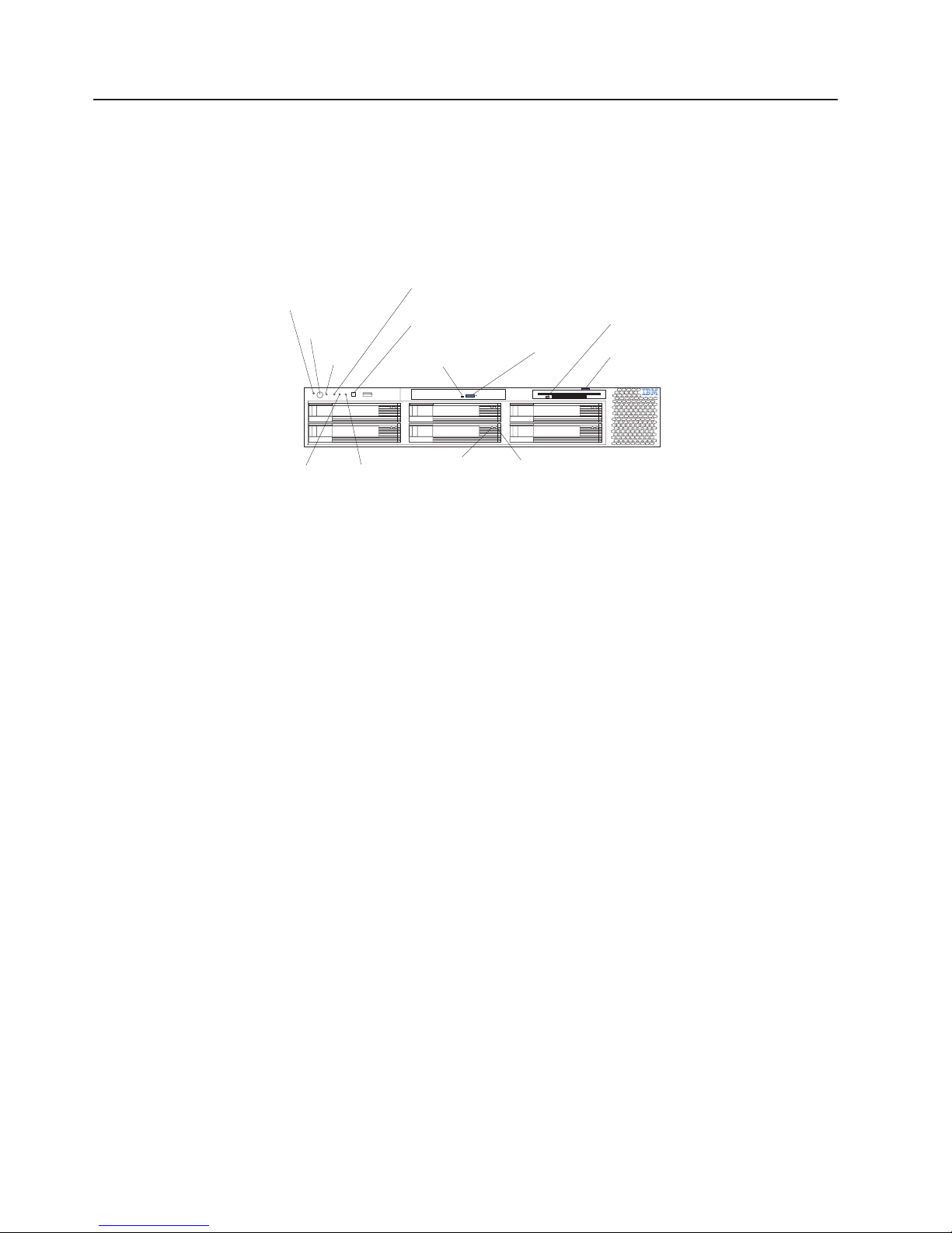
Front view
Power-on
LED (green)
Power-control
button
Reset
button
SCSI or IDE
bus activity LED
(green)
System-error
(amber)LED
CD-ROM drive
activity (green)LED
CD-eject button
Diskette drive
activity
LED
(green)
Diskette-eject
button
System
identification LED
(blue)
Information
(amber)
LED
Hard disk drive
activity
LED
(green)
Hard disk drive
status
LED
(amber)
Power-on LED: This green light-emitting diode (LED) is lit and stays on when you
turn on your server and flashes when the server is in Standby mode.
Attention: If the power-on LED is off, it does not mean there is no electrical
current present in the server. The LED might be burned out. To remove all electrical
current from the server, you must unplug the server power cords from the electrical
outlets or from the uninterruptible power device.
Power-control button: Press this button to manually turn on the server and put the
server in Standby mode (see “Server power features” on page 6).
Reset button: Press this button to reset the server and run the power-on self-test
(POST). Yo u might need to use a pen or the end of a straightened paper clip to
press the button.
SCSI or IDE bus activity LED: This LED is on when there is activity on the SCSI
or IDE bus.
System-error LED: This amber LED is lit when a system error occurs. An LED on
the diagnostic LED panel will also be on to further isolate the error.
CD-ROM drive activity LED: When this LED is lit, it indicates that the CD-ROM
drive is in use.
CD-eject button: Press this button to release a CD from the drive.
Diskette drive activity LED: When this LED is lit, it indicates that the diskette drive
is in use.
Diskette-eject button: Press this button to release a diskette from the drive.
Hard disk drive activity LED: Each of the hot-swap drives has a hard disk drive
activity LED. When this green LED is flashing, the controller is accessing the drive.
4 xSeries 345 Type 8670: Hardware Maintenance Manual and Troubleshooting Guide
Page 13
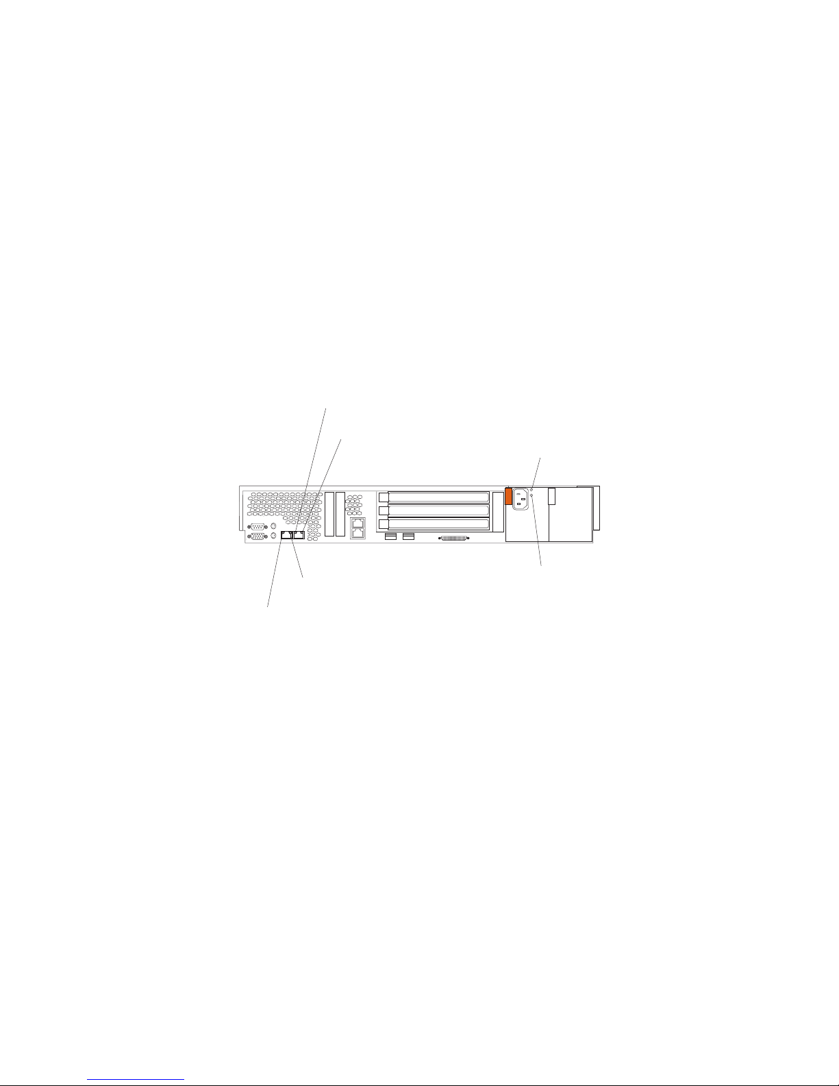
Rear view
Hard disk drive status LED: Each hot-swap drive has a hard disk drive status
LED. When this amber LED is lit continuously, the drive has failed. If a RAID
adapter is installed in the server, when the LED flashes slowly (one flash per
second), the drive is being rebuilt. When the LED flashes rapidly (three flashes per
second), the controller is identifying the drive.
Information LED: This amber LED is lit when the information log contains
information about certain conditions in your server that might affect performance.
For more information, see “Diagnostic panel LEDs” on page 33.
System-identification LED: This blue LED is lit in response to a programmed
condition, or it can be turned on remotely by the system administrator to aid in
server identification for maintenance. The system administrator can turn off the
system identification LED after maintenance is complete.
This section identifies the indicators on the rear of your server.
Ethernet 2 activity
(green)
Ethernet 2 link status
(green)
LED
LED
AC power
(green)
LED
Ethernet 1
(green)
Ethernet 1 link status
(green)
activity LED
LED
DC power
(green)
LED
Ethernet 2 activity LED: This green LED is lit when the server is transmitting or
receiving signals to the Ethernet LAN that is connected to Ethernet port 2.
Ethernet 2 link status LED: This green LED is lit when there is an active link
connection on the 10BASE-T, 100BASE-TX, or 1000BASE-TX interface for Ethernet
port 2.
AC power LED: This green LED provides status information about the power
supply. During typical operation, both the ac and dc power LEDs are lit. For any
other combination of LEDs, see “Power supply LEDs” on page 31.
DC power LED: This green LED provides status information about the power
supply. During typical operation, both the ac and dc power LEDs are lit. For any
other combination of LEDs, see “Power supply LEDs” on page 31.
Ethernet 1 link status LED: This green LED is lit when there is an active link
connection on the 10BASE-T, 100BASE-TX, or 1000BASE-TX interface for Ethernet
port 1.
Ethernet 1 activity LED: This green LED is lit when the server is transmitting or
receiving signals to the Ethernet LAN that is connected to Ethernet port 1.
Chapter 1. General information 5
Page 14
Server power features
This section contains information about how to properly turn your server on and off.
Turning on the server
You can turn on the server in any of the following ways:
v If the power cords are connected to a power source, you can press the
power-control button on the front of the server.
Note: Yo u can install a circular disk over the power-control button to prevent
accidental manual power-off. This disk, known as the power-control-button shield,
comes with your server.
v If the server is turned on and a power failure occurs, it restarts automatically
when power is restored.
v Yo u can turn on the server by using the Integrated System Management
Processor (ISMP).
v Yo u can turn on the server by using the optional Remote Supervisor Adapter.
v If your operating system supports the Wake on LAN® feature, the Wake on LAN
feature can turn on the server.
Complete the following steps to manually turn on the server:
1. Review the information in “Safety information” on page 125.
2. Turn on all external devices, such as the monitor.
3. Plug the server power cords into the power source.
4. Press the power-control button on the front of the server.
While the server is powering up, the power-on LED on the front of the server
Note:
is lit.
Turning off the server
Complete the following steps to manually turn off the server:
1. Review the information in “Safety information” on page 125.
2. See your operating system documentation for the proper procedure to shut
down the operating system.
Statement 5:
CAUTION:
The power control button on the device and the power switch on the
power supply do not turn off the electrical current supplied to the device.
The device also might have more than one power cord. To remove all
electrical current from the device, ensure that all power cords are
disconnected from the power source.
2
1
6 xSeries 345 Type 8670: Hardware Maintenance Manual and Troubleshooting Guide
Page 15

Standby mode
3. Press the power-control button on the front of the server. This will put the server
in Standby mode.
4. Disconnect the server from the power source.
Notes:
a. After you turn off the server, wait at least 5 seconds before you turn on the
server again.
b. Yo u might need to press and hold the power-control button for more than 4
seconds to cause an immediate shutdown of the server and to force the
power off. You can use this feature if the operating system stops functioning.
Standby mode refers to the condition in which the server operating system is not
running and all core logic is shut down except for the service processor.
Complete the following steps to put the server into Standby mode:
1. See the operating-system documentation for the proper procedure to shut down
the operating system.
Note: Each operating system is different. Read all the documentation about
shutting down the operating system before continuing.
2. Press the power-control button on the front of the server.
can put the server into Standby mode remotely by using the service processor.
You
Chapter 1. General information 7
Page 16

8 xSeries 345 Type 8670: Hardware Maintenance Manual and Troubleshooting Guide
Page 17

Chapter 2. Configuring your server
The following configuration programs are provided with your server:
v ServerGuide Setup and Installation CD
The ServerGuide Setup and Installation CD provides software setup tools and
installation tools that are specifically designed for your IBM server. Use this CD
during the initial installation of your server to configure basic hardware features,
such as ServeRAID™ and integrated RAID, and to simplify your network
operating system (NOS) installation. (See “Using the ServerGuide Setup and
Installation CD” for more information.)
v Configuration/Setup Utility program
This program is part of the basic input/output system (BIOS) code that comes
with your server. Yo u can use this program to configure serial port assignments,
change interrupt request (IRQ) settings, change the drive startup sequence, set
the date and time, and set passwords. You also can use this program to view the
system configuration settings, for example, the number of installed
microprocessors, the amount of installed memory, the BIOS diagnostics version
level, and so on. See “Using the Configuration/Setup Utility program” on page 11
for more information.
v ServeRAID programs
The ServeRAID programs come with your server. If your server has a ServeRAID
adapter installed or if you are using the RAID capabilities of the integrated SCSI
controller, use the ServeRAID Manager program to define and configure your
disk-array subsystem before you install your operating system. See “Using
ServeRAID Manager” on page 13 for more information.
v LSI Logic Configuration Utility
With the built-in LSI Logic Configuration Utility program, you can configure the
integrated SCSI controller and the devices that attach to it. See “Using the LSI
Logic Configuration Utility program” on page 20.
v Integrated System Management
To update the Integrated System Management (ISM) firmware, see “Updating the
integrated system-management firmware” on page 21 for more information.
v Ethernet controller configuration process
For instructions to configure the integrated Ethernet controller, see “Configuring
the Ethernet controller” on page 21.
v IBM Director
IBM Director is a work-group-hardware-management tool that you can use to
centrally manage xSeries servers; IBM Netvista, IntelliStation®, and ThinkPad
computers; and non-IBM Intel-microprocessor-based systems. IBM Director
automates tasks such as inventory-taking, monitoring of environmental sensors
(such as temperature, voltage and fans), alerting, and system-health information.
For more information and instructions about IBM Director, see the IBM Director
User’s Guide on the CD that comes with your server.
®
Using the ServerGuide Setup and Installation CD
The ServerGuide Setup and Installation CD includes an easy-to-use setup and
installation program that is specifically designed for your IBM server. The
ServerGuide program detects the server model and hardware options that are
installed and uses that information during setup to configure the hardware. The
© Copyright IBM Corp. 2004 9
Page 18

ServerGuide program simplifies network operating system (NOS) installations by
providing updated device drivers and, in some cases, installing them automatically.
If a later version of the ServerGuide program is available, you can download a free
image of the ServerGuide Setup and Installation CD, or you can purchase the CD.
To download the latest ServerGuide program, go to the IBM ServerGuide Web page
at http://www.ibm.com/pc/qtechinfo/MIGR-4ZKPPT.html. To purchase the latest
ServerGuide Setup and Installation CD, see the “ServerGuide Updates” flyer that
comes with your server library, or go to the ServerGuide fulfillment Web site at
http://www.ibm.com/pc/coupon/.
The ServerGuide program has the following features to make setup easier:
v An easy-to-use interface with online help
v Diskette-free setup and configuration programs that are based on detected
v A system BIOS update program, which updates the BIOS code directly from the
v Device drivers that are provided for your server model and detected hardware
v NOS partition size and file-system type that are selectable during setup
System partition
The ServerGuide program creates a 50 MB system partition on the default drive.
The system partition contains server-specific utility programs such as service
processor disk operating system (DOS) utilities, system diagnostics, flash BIOS
updates, and other programs. Programs in the system partition vary by server
model, and not all server models run utility programs from the system partition. To
determine which ones do, start the ServerGuide Setup and Installation CD and view
the online overview.
hardware
CD
After setup is complete, you can access programs in the system partition by
restarting the server and pressing Alt+F1 when the prompt is displayed. The
System Partition menu displays the programs that are available on your server
model.
Typical NOS installation
You can use the ServerGuide program to shorten your installation time. The
ServerGuide program provides the device drivers that are required for your
hardware and for the NOS that you are installing. This section describes a typical
ServerGuide NOS installation.
Note: Features and functions can vary slightly with different versions of the
ServerGuide program.
1. After you have completed the setup process, the NOS installation program
starts. (You will need your NOS CD to complete the installation.)
2. The ServerGuide program stores information about the server model, service
processor, hard disk drive controllers, and network adapters. Then, the program
checks the CD for newer device drivers. This information is stored and then
passed to the NOS installation program.
3. With some NOS installations, you can create a NOS-replication diskette for
setting up additional servers. This diskette contains the Internet protocol (IP)
address, server name, and other selections.
4. The ServerGuide program presents NOS partition options that are based on
your NOS selection and the installed hard disk drives.
10 xSeries 345 Type 8670: Hardware Maintenance Manual and Troubleshooting Guide
Page 19

5. If you are installing the NOS from diskette, the ServerGuide program lists the
diskettes that you must create and the optional diskettes that you might want to
create. The diskettes that you can create are the device-driver diskettes for the
installed adapters or controllers.
6. The ServerGuide program prompts you to insert your NOS CD and restart the
server. At this point, the installation program for the NOS automatically
completes the installation.
Setting up or updating multiple servers
You can use the ServerGuide program to create diskettes that help you set up or
update multiple servers. You can modify information on the diskettes as you use
them to set up or update other servers.
Note: Availability and function can vary by server model and by the hardware that
is installed.
You can create a setup-replication diskette, which contains your hardware
configuration selections. Use this diskette to replicate selections to other servers
that are of the same model.
You can create a NOS-replication diskette, which contains information that you need
to complete multiple installations. Not all operating systems support NOS-replication
diskettes.
Installing your NOS without ServerGuide
If you have already configured the server hardware and you decide not to use the
ServerGuide program to install your NOS, complete the following steps to download
the latest NOS installation instructions from the IBM Support Web page:
1. Go to http://www.ibm.com/support.
2. Under Browse, click Servers.
3. From the Family drop-down list, select your server model.
4. If NOS installation instructions are available for your server model, OS
installation is in the list in the left pane of the Web page. Click OS installation
and select the instructions for your NOS.
Using the Configuration/Setup Utility program
This section provides instructions to start the Configuration/Setup Utility program
and descriptions of the available menu choices.
Starting the Configuration/Setup Utility program
To start the Configuration/Setup Utility program, complete the following steps:
1. Turn on the server, and watch the monitor screen.
2. When the message Press F1 for Configuration/Setup appears, press F1.
Notes:
a. If you have set both levels of passwords (power-on and administrator), you
must type the administrator password to access the full Configuration/Setup
Utility main menu. Without the administrator password, limited
Configuration/Setup Utility program functions are available.
b. Yo u can set an administrator password only if the optional IBM Remote
Supervisor Adapter is installed in your server
Chapter 2. Configuring your server 11
Page 20

3. Follow the instructions that appear on the screen.
Using passwords
The System Security choice appears only on the full Configuration/Setup Utility
menu. After you select this choice, you can implement two levels of password
protection: power-on password and administrator password.
Power-on password
After you set a power-on password, you can enable the Unattended-Start mode.
This locks the keyboard and mouse but enables the system to start the operating
system. The keyboard and mouse remain locked until you type the correct
password.
You can use any combination of up to seven characters (A–Z, a–z, and 0–9) for
your power-on password. Keep a record of your password in a secure place. When
a power-on password is set, POST is not completed until you type the password. If
you forget the power-on password, you can regain access to the server through one
of the following methods:
v If an administrator password is set, type the administrator password at the
v Remove the battery, and then reinstall the battery (see “Replacing the battery” on
v Change the position of the power-on password override switch (switch 6 on
power-on prompt. (If necessary, see “Administrator password” for details.) Start
the Configuration/Setup Utility program, and change the power-on password.
page 69 for instructions).
switch block 1) to bypass the power-on password check. You can then start the
Configuration/Setup Utility program and change the power-on password.
Notes:
1. Before changing any switch settings or moving any jumpers, turn off the
server; then, disconnect all power cords and external cables.
2. Any system-board switch or jumper blocks that are not shown in the
illustrations in this book are reserved.
3. Changing the position of the power-on password override switch bypasses
the power-on password check the next time the server is turned on. You do
not need to move the switch back after the password is overridden. The
default position is Off. To bypass the power-on password check, move the
switch to the opposite position.
4. Changing the position of this switch does not affect the administrator
password.
Administrator password
Select this choice to set an administrator password. The administrator password
provides access to all choices on the Configuration/Setup Utility main menu.
Note: This choice is available on the Configuration/Setup Utility menu only if the
optional IBM Remote Supervisor Adapter is installed in your server.
When you use an administrator password, you can set, change, or delete both the
administrator and power-on passwords and allow a user to change a power-on
password. Yo u can use any combination of up to seven characters (A–Z, a–z, and
0–9) for your administrator password. Keep a record of your password in a secure
place.
12 xSeries 345 Type 8670: Hardware Maintenance Manual and Troubleshooting Guide
Page 21

Attention: If an administrator password is set and then forgotten, it cannot be
overridden or removed. You must replace the system board.
The following table provides a summary of the password features.
Table 2. Power-on and administrator password features
Type of password Features
Power-on password v Type the password to complete the system startup.
v All choices are available on the Configuration/Setup Utility main menu.
Administrator password v No password is required to complete the system startup.
v Type the password to access the Configuration/Setup Utility program.
v All choices are available on the Configuration/Setup Utility main menu.
Administrator and power-on
password
v Yo u can type either password to complete the system startup.
v The administrator password provides access to all choices on the
Configuration/Setup Utility main menu. Yo u can set, change, or delete both the
administrator and power-on passwords and allow a user to change a power-on
password.
v The power-on password provides access to a limited set of choices on the
Configuration/Setup Utility main menu. This limited access might include changing
or deleting the power-on password.
Using ServeRAID Manager
You can use the ServeRAID Manager program, provided on the IBM ServeRAID
Support CD, to:
v Configure a redundant array of independent disks (RAID)
v Restore a SCSI hard disk drive to factory-default settings, erasing all data
v View your RAID configuration and associated devices
v Monitor operation of your RAID controllers
ServeRAID Manager program operates in two ways:
The
v Startable CD mode
v As an installed software program
The information in this section provides instructions for running ServeRAID Manager
in Startable CD mode to configure your integrated SCSI controller with RAID
capabilities and perform an initial RAID configuration on your server. See the
ServeRAID documentation on the IBM ServeRAID Support CD for additional
information about RAID technology and instructions for using ServeRAID Manager
to configure your integrated SCSI controller with RAID capabilities. For information
about installing ServeRAID Manager, see the documentation on the IBM ServeRAID
Support CD.
Notes:
1. The integrated SCSI controller with RAID capabilities in your server supports
only RAID level-1 with a hot spare device. Installing an optional ServeRAID-5i
controller provides additional RAID levels. If a ServeRAID-5i controller is
installed and later removed, you must re-enable the on-board SCSI controller
using the Configuration/Setup Utility program (see “Starting the
Configuration/Setup Utility program” on page 11).
2. If you install a different type of RAID adapter in your server, use the
configuration method supplied with the RAID adapter to view or change SCSI
settings for attached devices.
Chapter 2. Configuring your server 13
Page 22
When you run the ServeRAID Manager program from the startable IBM ServeRAID
Support CD, you are using Startable CD mode, in which you can configure your
controller before you install your operating system.
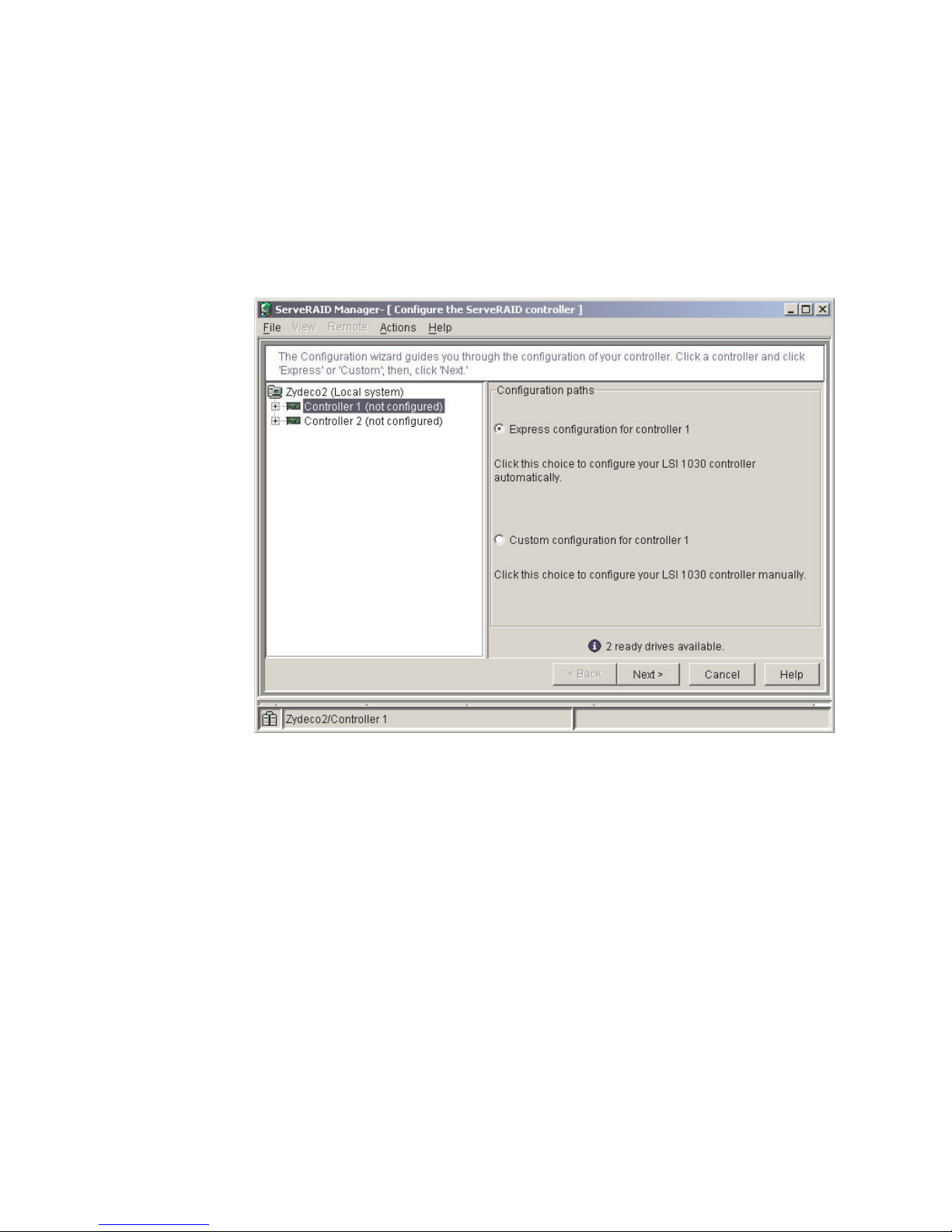
To run the ServeRAID Manager program in Startable CD mode, turn on the server;
then, insert the IBM ServeRAID Support CD into the CD-ROM drive. If the
ServeRAID Manager program detects an unconfigured controller and ready drives,
the program automatically starts the Configuration wizard, and a window similar to
that shown in Figure 1 opens.
Figure 1. Configuration wizard window
Configuring the controller
You can use the Configuration wizard to configure your controller. The Configuration
wizard provides two configuration options: Express and Custom. Express
configuration automatically configures your controller, and you can use Custom
configuration to configure your controller manually.
Note: If the integrated RAID controller has two channels, it will appear in the
ServeRAID Manager tree as two controller objects. However, you can configure
only one array and one RAID level-1 logical drive.
Using Express configuration
Express configuration automatically configures your controller, creates an array by
grouping together the first two physical drives that appear in the ServeRAID
Manager tree, and it creates a RAID level-1 logical drive.
Complete the following steps to use Express configuration:
1. In the ServeRAID Manager tree, click the controller.
2. Click Express configuration.
14 xSeries 345 Type 8670: Hardware Maintenance Manual and Troubleshooting Guide
Page 23
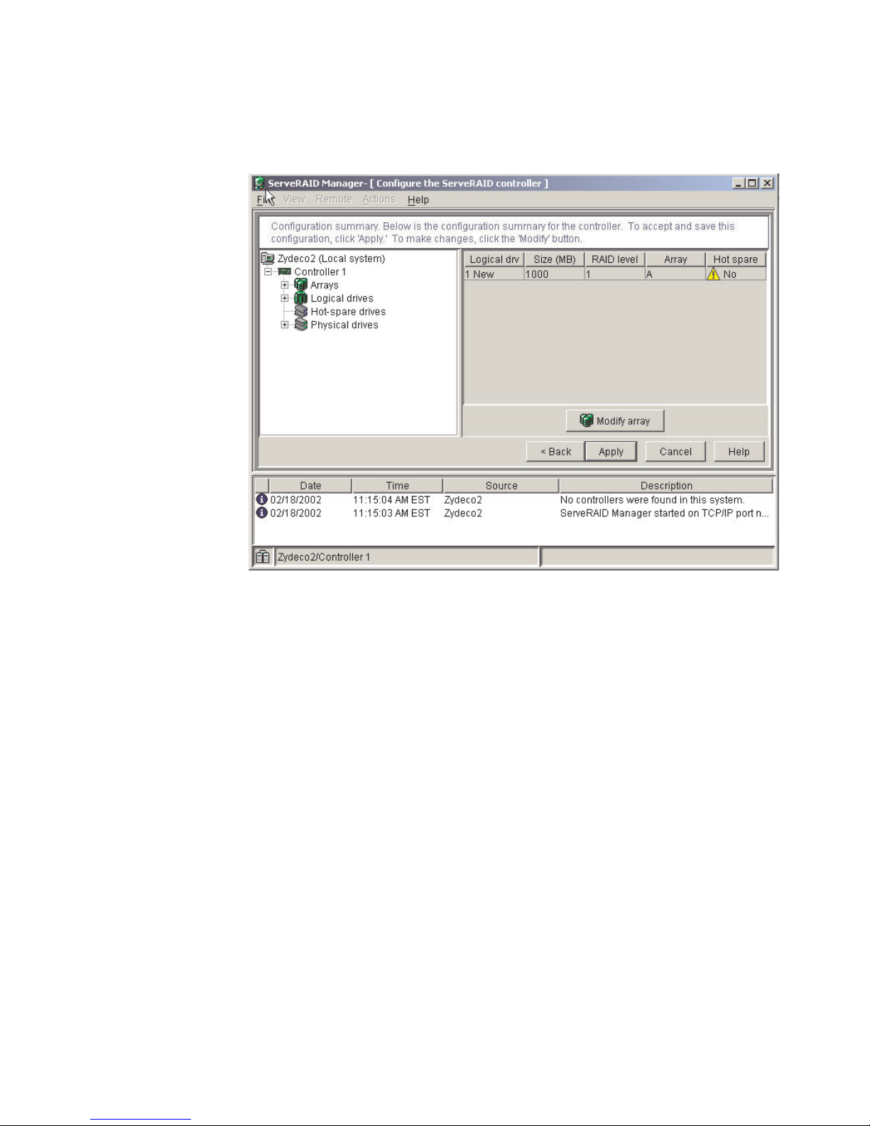
3. Click Next. The “Configuration summary” window opens.
4. Review the information that is displayed in the Configuration summary window.
To change the configuration, click Modify arrays.
Figure 2. Configuration summary window
5. Click Apply; then, click Yes when asked if you want to apply the new
configuration. The configuration is saved in the controller and in the physical
drives.
6. Exit from the ServeRAID Manager program and remove the CD from the
CD-ROM drive.
7. Restart the server.
Using Customer configuration
To configure your controller manually, use Custom configuration to select which two
physical drives you want to configure and create a hot-spare drive.
Complete the following steps to use Custom configuration:
1. In the ServeRAID Manager tree, click the controller.
2. Click Custom configuration.
Chapter 2. Configuring your server 15
Page 24
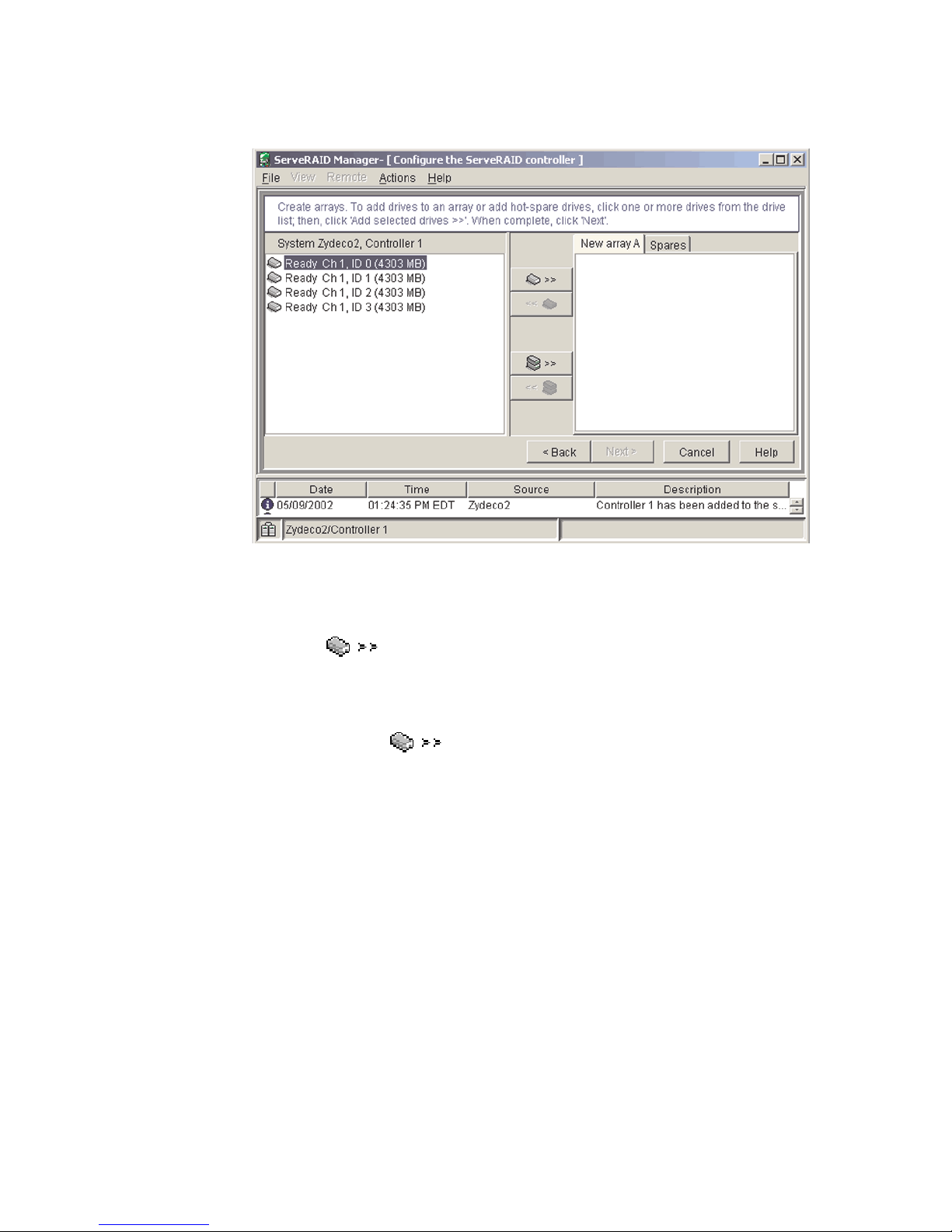
3. Click Next. The “Create arrays” window opens.
Figure 3. Create arrays window
4. From the list of ready drives, select the two drives you want to move to the
array.
5. Click
6. Complete the following steps, if you want to configure a hot-spare drive:
(Add selected drives) to add the drives to the array.
a. Click the Spares tab.
b. Select the physical drive you want to designate as the hot-spare drive;
then, click
(Add selected drives).
16 xSeries 345 Type 8670: Hardware Maintenance Manual and Troubleshooting Guide
Page 25
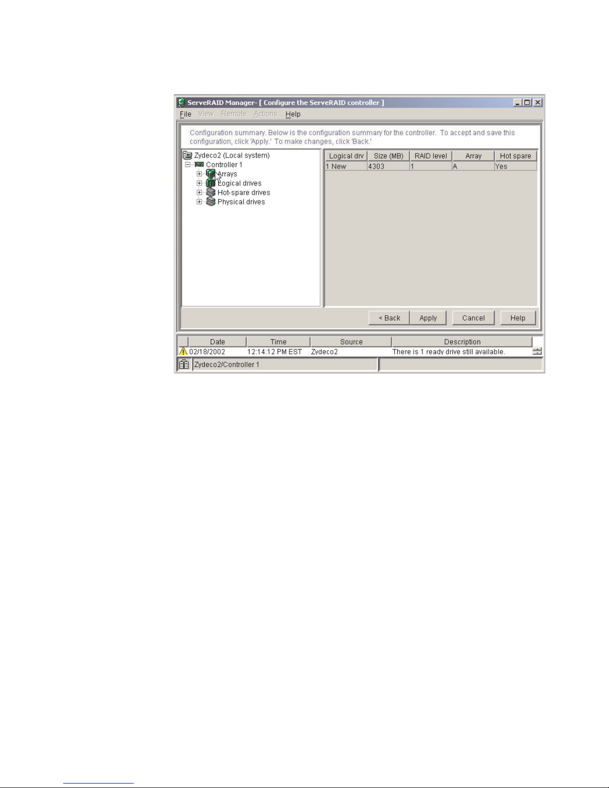
7. Click Next. The Configuration summary window opens.
Figure 4. Configuration summary window
8. Review the information that is displayed in the “Configuration summary”
window. To change the configuration, click Back.
9. Click Apply; then, click Yes when asked if you want to apply the new
configuration. The configuration is saved in the controller and in the physical
drives.
10. Exit from the ServeRAID Manager program, and remove the CD from the
CD-ROM drive.
11. Restart the server.
Viewing your configuration
You can use ServeRAID Manager to view information about RAID controllers and
the RAID subsystem (such as arrays, logical drives, hot-spare drives, and physical
drives).
Chapter 2. Configuring your server 17
Page 26
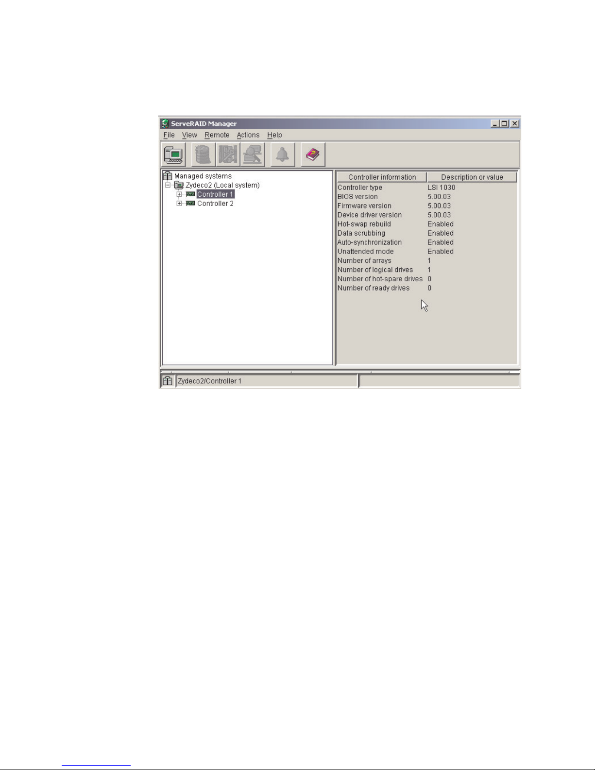
To view information, expand the ServeRAID Manager tree; then, click the relevant
tree object. Detailed information about the selected device appears in the right
pane.
Figure 5. ServeRAID Manager window
To display available actions for an item, click the item in the ServeRAID Manager
tree and click Actions.
18 xSeries 345 Type 8670: Hardware Maintenance Manual and Troubleshooting Guide
Page 27
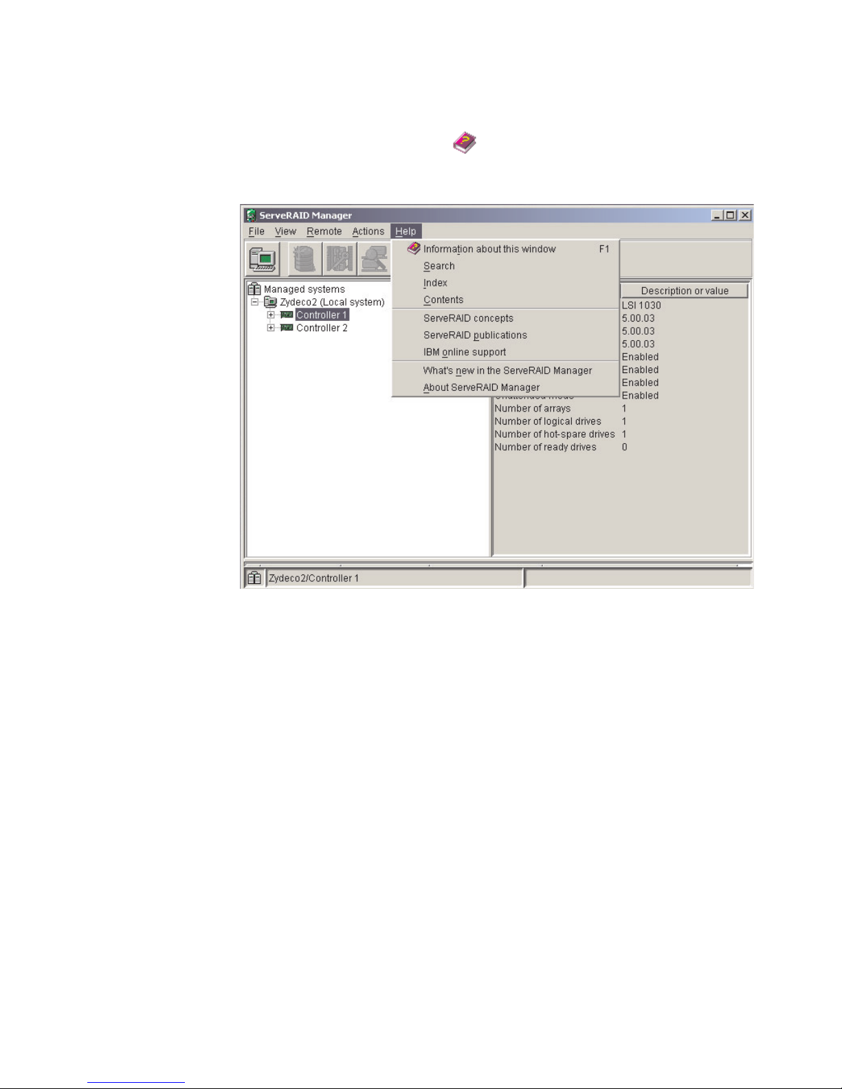
Getting assistance
For more information about ServeRAID Manager, see the online help system. To
start the help system, either click
(Information about this window) on the
toolbar, or select an item from the Help menu.
Figure 6. ServeRAID Manager help menu
The help system (ServeRAID Assist) will open within the ServeRAID Manager
interface.
Chapter 2. Configuring your server 19
Page 28
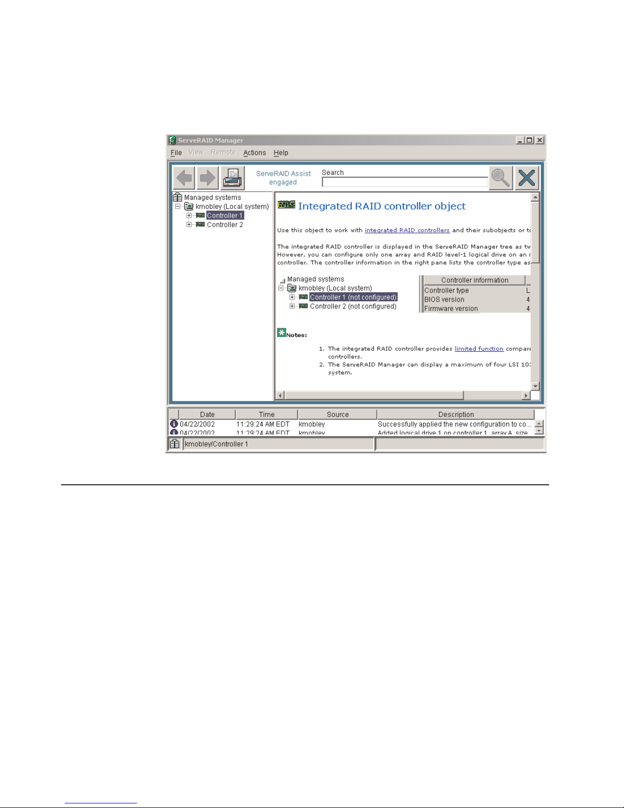
To learn more about the ServeRAID Manager tree objects and the actions that
apply to them, select a tree object, and click Actions → Hints and tips. ServeRAID
Assist will start, and information about the tree object will appear in the right pane
of ServeRAID Manager.
Figure 7. Hints and tips feature
Using the LSI Logic Configuration Utility program
You can use the built-in, menu-driven LSI Logic Configuration program to:
v Perform a low-level format on a hard disk drive
v Set the SCSI device scan order
v Set the SCSI ID for a controller
Notes:
1. The integrated SCSI controller with RAID capabilities in your server supports
2. If your server has a ServeRAID-5i controller installed, you can use ServeRAID
RAID level 1 operation.
Manager to configure the integrated SCSI controller with RAID capabilities for
additional RAID levels. If a ServeRAID-5i controller is installed and later
removed, you must re-enable the on-board SCSI controller in using the
Configuration/Setup Utility program (see “Starting the Configuration/Setup Utility
program” on page 11).
20 xSeries 345 Type 8670: Hardware Maintenance Manual and Troubleshooting Guide
Page 29

Complete the following steps to start the LSI Logic Configuration Utility program:
1. Turn on the server and watch the monitor screen.
2. When the Press CTRL C to start LSI Logic Configuration Utility prompt
appears, press Ctrl+C.
Note: If an administrator password has been set, a prompt appears asking you
to type the password to start the LSI Logic Configuration Utility program.
3. Use the arrow keys to select a controller (channel) from the list of adapters;
then, press Enter.
4. Follow the instructions on the screen to change the settings of the selected
items; then, press Enter.
You can use the LSI Logic Configuration Utility program to perform a low-level
format on a SCSI hard disk drive. Complete the following steps to format a drive:
Attention: The Low-Level Format program erases all data and programs. Backup
any data before running the Low-Level Format program.
1. Select the controller channel for the drive from the list of adapters.
2. Select Device Properties.
3. Use the arrow keys to highlight the drive to format.
4. Use the arrow keys or the End key to scroll to the right.
5. Highlight the Format item; then, press Enter to start.
Updating the integrated system-management firmware
To update the integrated system-management (ISM) firmware for the integrated
system-management processor (ISMP), you must download the image of the
Integrated System Management Firmware Update Utility program for your server
from the IBM Support Web site at http://www.ibm.com/support on the World Wide
Web. Yo u can then run the Integrated System Management Firmware Update Utility
program to create an Integrated System Management Firmware Update Utility
diskette that is used to update the ISM firmware. This diskette updates the ISM
firmware only and does not affect any device drivers.
Complete the following steps to update the ISMP firmware:
1. Turn off your server.
2. Insert the diskette into the diskette drive.
3. Turn on your server. If your server does not start from the diskette drive, use the
Configuration/Setup Utility program to configure the diskette drive as a startup
device. See “Using the Configuration/Setup Utility program” on page 11. Then,
go back and start with step 1.
4. From the main menu, select Update System Management Firmware and
press Enter.
5. Follow the on-screen instructions to complete the update.
Configuring the Ethernet controller
The server comes with an integrated dual-port Ethernet controller. This controller
provides an interface for connecting to 10-Mbps, 100-Mbps, and 1000-Mbps
networks and provides full-duplex (FDX) capability, which enables simultaneous
transmission and reception of data on the Ethernet local area network (LAN).
Chapter 2. Configuring your server 21
Page 30

To use the Ethernet controller, connect a Category 5 or higher unshielded
twisted-pair (UTP) cable to either of the two Ethernet ports on the rear panel of the
server.
The Ethernet connectors on the rear panel each have two LEDs. When the
Ethernet link-status LED is on, there is an active connection on the Ethernet port.
When the Ethernet transmit/receive TX/RX LED is on, there is activity between the
server and the network. For a description of the server Ethernet ports, see
t“Ethernet ports” on page 77.
When you connect the server to the network, the Ethernet controller automatically
detects the data-transfer rate (10 Mbps, 100 Mbps, or 1000Mbps) on the network
and sets the controller to operate at the appropriate rate. In addition, if the Ethernet
port that the server is connected to supports auto-negotiation, the Ethernet
controller will set the appropriate duplex state. That is, the Ethernet controller will
adjust to the network data rate, whether the data rate is standard Ethernet
(10BASE-T), Fast Ethernet (100BASE-TX), Gigabit Ethernet (1000BASE-T), half
duplex (HDX), or full duplex (FDX). The controller supports half-duplex (HDX) and
full-duplex (FDX) modes at all speeds.
The Ethernet controller is a PCI Plug and Play device. Yo u do not need to set any
jumpers or configure the controller for the operating system before you use the
controller. However, you must install a device driver to enable the operating system
to access the controller. The device driver is provided on the ServerGuide Setup
and Installation CD.
If you install an optional Ethernet adapter or use both Ethernet ports on your server,
you can use optional modes, such as teaming, priority packets, and virtual LANs,
which provide higher performance and throughput for the server. These modes
apply to the integrated Ethernet controller and to the controllers on the supported
Ethernet adapters.
Teaming mode
Teaming options increase throughput and fault tolerance when running with
Windows NT®, Windows® 2000, or NetWare 4.1x or later.
v Adapter fault tolerance (AFT) provides automatic redundancy for the Ethernet
controller. If the primary controller fails, the optional Ethernet adapter takes over.
Adapter fault tolerance supports from 2 to 4 controllers per team.
v Adaptive load balancing (ALB) enables you to balance the transmission data
flow among 2 to 4 Ethernet controllers. ALB also includes the AFT option. Yo u
can use ALB with any 100BASE-TX or 1000BASE-T switch.
v Cisco Fast EtherChannel (FEC) creates a team of 2 to 4 Ethernet controllers to
increase transmission and reception throughput. FEC also includes the AFT
option. Yo u can only use FEC with a switch that has FEC capability.
Priority packet mode
Priority packet is a traffic-prioritization utility that you can use to set up filters to
process high-priority traffic before normal traffic. You can send information from
critical nodes or applications with an indicated priority. Because you set this priority
at the host or entry point of the network, the network devices can base forwarding
decisions on priority information defined in the packet.
Priority packet information is available on the IBM Networking Web site at
http://www.ibm.com/networking/support.
22 xSeries 345 Type 8670: Hardware Maintenance Manual and Troubleshooting Guide
Page 31

Priority packet prioritizes traffic based on priority filters. These are parameters you
assign to outgoing (transmit) packets. Using the Priority Filter wizard, you can set
up predefined or custom priority filters based on a node (MAC) address, Ethernet
type, or by various properties of the protocol and port. Priority packet provides two
different methods for prioritizing traffic: IEEE 802.1p tagging and high priority queue.
IEEE 802.1p is an IEEE standard for tagging, or adding additional bytes of
information to packets with different priority levels. Packets are tagged with 4
additional bytes, which increase the packet size and indicate a priority level. When
you send these packets out on the network, the higher priority packets are
transferred first. Priority packet tagging (also known as traffic class expediting)
enables the Ethernet controller to work with other elements of the network (such as
switches and routers) to deliver priority packets first. You can assign specific priority
levels from 0 (low) to 7 (high).
You can assign values to packets based on their priorities when you use the IEEE
802.1p standard for packet tagging. This method requires a network infrastructure
that supports packet tagging. The routing devices receiving and transferring these
packets on the network must support 802.1p for tagging to be effective.
After you set up the priority filter in priority packet, you must start PROSet, click the
Advanced tab, and select QoS Packet Tagging from the list.
Note: IEEE 802.1p tagging increases the size of the packets it tags. Some hubs
and switches will not recognize the larger packets and will drop them. Check the
hub or switch documentation to see if they support 802.1p. (You can configure the
switch to strip the tags from the packets and send it on to the next destination as
normal traffic.) If these devices do not support 802.1p or if you are not sure, use
high priority queue (HPQ) to prioritize network traffic.
The requirements for effectively using IEEE 802.1p tagging are:
v The other devices receiving and routing 802.1p tagged packets must support
802.1p.
v The adapters on these devices must support 802.1p. The Ethernet controller in
the server, all IBM 10/100 Ethernet Security Adapters, and IBM 10/100 Ethernet
Server Adapters support 802.1p.
v The adapter cannot be assigned to an adapter team.
v If you are setting up VLANs and packet tagging on the same adapter, you must
start PROSet, click the Advanced tab, and select QoS Packet Tagging from the
list.
the network infrastructure devices do not support IEEE 802.1p or you are not
If
sure, you can still define filters and send packets as high priority. Although high
priority queue (HPQ) does not provide the precise priority levels of 802.1p tagging,
it does assign traffic as either high or low priority and sends high priority packets
first. Therefore, if there are multiple applications on a system sending packets, the
packets from the application with a filter are sent out first. HPQ does not change
network routing, nor does it add any information to the packets.
To assign HPQ, you can specify it using priority packet mode when you create or
assign a filter.
To effectively use HPQ, the adapter cannot be assigned to an adapter team.
Chapter 2. Configuring your server 23
Page 32

Virtual LAN mode
A virtual LAN (VLAN) is a logical grouping of network devices put together as a
LAN, regardless of their physical grouping or collision domains. Using VLANs
increases network performance and improves network security.
VLANs offer you the ability to group users and devices together into logical
workgroups. This can simplify network administration when connecting clients to
servers that are dispersed geographically across a building, campus, or enterprise
network.
Typically, VLANs are configured at the switch and any system can be a member of
one VLAN per installed network adapter. The Ethernet controller supersedes this by
communicating directly with the switch, enabling multiple VLANs on a single
network adapter (up to 64 VLANs).
When you set up VLAN membership, the Ethernet controller must be attached to a
switch that has VLAN capability. Yo u also need to use Windows 2000, Windows NT
4.0 or later, or Novell NetWare 4.1x or later.
Notes®:
1. Windows NT versions prior to 4.0 do not support VLANs.
2. VLANs require Windows NT 4.0 with Service Pack 3.0 and the network driver
3. In Windows NT, VLANS cannot be implemented on controllers that have been
interface specifications (NDIS) driver hotfix from Microsoft®.
configured for teaming options. Netware can support teaming options and
VLANS on the same adapters.
Complete the following steps to join a VLAN from Windows NT 4.0:
1. Create a VLAN on the switch. Use the parameters you assign there to join the
VLAN from the server. See the switch documentation for more information.
2. Double-click the Start Proset icon in the Control Panel window.
3. On the Adapters page, right click on the adapter that you want to be on the
VLAN.
4. In IBMSet, click Add VLAN for the first adapter or click Join VLAN for
remaining adapters. Note that VLANs cannot be assigned to adapters that are
already defined to have an adapter teaming option.
5. Type the VLAN ID and VLAN name. The VLAN ID must match the VLAN ID of
the switch. The VLAN name is for information only and does not need to match
the name on the switch.
6. Repeat steps 3 through 5 for each VLAN you want the server to join. The
VLANs you add are listed on the Adapters page.
7. Click Close, and restart the server.
24 xSeries 345 Type 8670: Hardware Maintenance Manual and Troubleshooting Guide
Page 33

Chapter 3. Diagnostics
This section provides basic troubleshooting information to help you resolve some
common problems that might occur with your server.
If you cannot locate and correct the problem using the information in this section,
see Appendix A, “Getting help and technical assistance,” on page 123 for more
information.
General checkout
The server diagnostic programs are stored in upgradeable read-only memory
(ROM) on the system board. These programs are the primary method of testing the
major components of the server: the system board, Ethernet controller, video
controller, RAM, keyboard, mouse (pointing device), diskette drive, serial ports, and
hard disk drives. You can also use the diagnostic programs to test some external
devices. See “Diagnostic programs and error messages” on page 28.
If you cannot determine whether a problem is caused by the hardware or by the
software, run the diagnostic programs to test the hardware.
When you run the diagnostic programs, a single problem might cause several error
messages. When this occurs, work to correct the cause of the first error message.
After you correct the cause of the first error message, the other error messages
might not occur the next time you run the test.
A failed system might be part of a shared hard disk drive cluster (two or more
systems sharing one or more external storage devices). Before you run diagnostics,
verify that the failing system is not part of a shared hard disk drive cluster.
A system might be part of a cluster if:
v The system is identified as part of a cluster.
v One or more external storage units are attached to the system and at least one
of the attached storage units is also attached to another system or unidentifiable
source.
v One or more systems are located near the failing system.
If the failing system is suspected to be part of a shared hard disk drive cluster, run
all diagnostic tests except the diagnostic tests that test the storage unit (hard disk
drive residing in the storage unit) or the storage adapter attached to the storage
unit.
Notes:
1. For systems that are part of a shared hard disk drive cluster, run one test at a
time in looped mode. Do not run all tests in looped mode. This could enable the
hard disk drive diagnostic tests.
2. If multiple error codes are displayed, diagnose the first error code that is
displayed.
3. If the server stops with a POST error, go to “POST error codes” on page 102.
4. If the server stops and no error is displayed, go to “Undetermined problems” on
page 112.
5. For power supply problems, see “Power-supply LED errors” on page 101.
6. For safety information, see “Safety information” on page 125.
© Copyright IBM Corp. 2004 25
Page 34

7. For intermittent problems, check the error log.
Follow the steps in this procedure to identify system problems.
001 IS THE SYSTEM PART OF A CLUSTER?
YES. Schedule maintenance for the system. Shut down all systems related
to the cluster. Run the storage test.
NO. Go to step 002.
002 IF THE SYSTEM IS NOT PART OF A CLUSTER:
1. Turn off the server and all external devices.
2. Check all cables and power cords.
3. Set all display controls to the middle position.
4. Turn on all external devices.
5. Turn on the server.
6. Record any POST error messages that are displayed on the screen. If
an error is displayed, look up the first error in the “POST error codes”
on page 102.
7. Check the information LED panel System Error LED; if it is on, see
“Diagnostic panel system-error LED” on page 86.
8. Check the system-error log. If the system recorded an error, see
Chapter 6, “Symptom-to-FRU index,” on page 83.
9. Start the diagnostic programs.
10. Check for the following responses:
v One beep.
v Readable instructions or the main menu.
DID YOU RECEIVE BOTH OF THE CORRECT RESPONSES?
003
NO. Find the failure symptom in Chapter 6, “Symptom-to-FRU index,” on
page 83.
YES. Run the diagnostic programs. If necessary, see “Diagnostic programs
and error messages” on page 28.
If you receive an error, see Chapter 6, “Symptom-to-FRU index,” on page
83.
If the diagnostic programs were completed successfully and you still
suspect a problem, see “Undetermined problems” on page 112.
Diagnostic tools overview
The following tools are available to help you identify and resolve hardware-related
problems:
v POST beep codes and error messages
The power-on self-test (POST) generates beep codes and messages to indicate
successful test completion or the detection of a problem. See “POST error logs”
on page 27 for more information.
v Error log
The POST error log contains the three most recent error codes and messages
that the system has generated during POST. The system-error log contains all
the error messages that were issued during POST.
To view the contents of the error logs, start the Configuration/Setup Utility
program; then, select Error Logs from the main menu. See “Viewing the
system-error log” on page 31 for more information.
26 xSeries 345 Type 8670: Hardware Maintenance Manual and Troubleshooting Guide
Page 35

v ServerGuide error symptoms
ServerGuide error symptoms are explained at “ServerGuide error symptoms” on
page 28.
v SCSI error messages
For information on SCSI errors, see “Small computer system interface messages”
on page 28 and “SCSI error codes” on page 108.
v Diagnostic programs and error messages
The server diagnostic programs are stored in read-only memory (ROM) on the
system board. These programs are the primary method of testing the major
components of your server. See “Diagnostic programs and error messages” on
page 28 for more information.
v Light Path Diagnostics
The Light Path Diagnostics™ feature provides a series of LEDs that are built into
your server so that you can quickly identify problems with server components by
following the path of LEDs. See “Light Path Diagnostics” on page 32 for more
information.
v Error symptom charts
These charts list problem symptoms, along with suggested steps to correct the
problems. See the “Error symptoms” on page 93 for more information.
POST error logs
When you turn on the server, it performs a series of tests to check the operation of
server components and some of the options installed in the server. This series of
tests is called the power-on self-test, or POST.
If POST finishes without detecting any problems, a single beep sounds, and the first
screen of your operating system or application program appears.
If POST detects a problem, more than one beep sounds, and an error message
appears on your screen. See “Beep symptoms” on page 83 and “POST error
codes” on page 102 for more information.
Notes:
1. If you have a power-on password or administrator password set, you must type
the password and press Enter, when prompted, before POST will continue.
2. A single problem might cause several error messages. When this occurs, work
to correct the cause of the first error message. After you correct the cause of
the first error message, the other error messages usually will not occur the next
time you run the test.
The POST error log contains the three most recent error codes and messages that
the system generated during POST. The system-error log contains all messages
issued during POST and all system status messages from the service processor.
You can view the contents of the system-error log from the Configuration/Setup
Utility program or from the diagnostic programs.
Viewing error logs from the Configuration/Setup Utility program
To view error logs from the Configuration/Setup Utility program, start the
Configuration/Setup Utility program; then, select Error Logs from the main menu.
See Chapter 2, “Configuring your server,” on page 9 for more information.
Chapter 3. Diagnostics 27
Page 36

Viewing error logs from diagnostic programs
To view error logs from diagnostic programs, complete the following steps:
1. Start the diagnostic programs.
2. Select Hardware Info from the top of the diagnostic programs screen.
3. Select System Error Log from the list that appears; then, follow the instructions
on the screen.
“Starting the diagnostic programs” on page 30 for more information.
See
ServerGuide error symptoms
Look for the symptom in the left column of the chart. Probable solutions to the
problem are in the right column.
Table 3. ServerGuide Setup and Installation CD
Symptom Suggested action
The ServerGuide Setup and Installation
CD will not start.
The SCSI RAID program cannot view all
installed drives, or the NOS cannot be
installed.
The Operating System Installation
program continuously loops.
The ServerGuide program will not start
your NOS CD.
The NOS cannot be installed; the option
is not available.
v Ensure that the server is supported and has a startable (bootable)
CD-ROM drive.
v If the startup (boot) sequence settings have been altered, ensure that
the CD-ROM drive is first in the startup sequence.
v If more than one CD-ROM drive is installed, ensure that only one drive
is set as the primary drive. Start the CD from the primary drive.
v Ensure that there are no duplicate SCSI IDs or IRQ assignments.
v Ensure that the hard disk drive is connected properly.
Make more space available on the hard disk.
Ensure that the ServerGuide program supports the NOS CD you have.
See the ServerGuide Setup and Installation CD label for a list of supported
NOS versions.
Ensure that your server supports the NOS. If the NOS is supported, either
there is no logical drive defined (SCSI RAID systems) or the ServerGuide
System Partition is not present. Run the ServerGuide program, and ensure
that setup is complete.
Small computer system interface messages
If you receive a SCSI error message, see “SCSI error codes” on page 108.
Note: If your server does not have a hard disk drive, ignore any message that
indicates that the BIOS is not installed.
Diagnostic programs and error messages
The server diagnostic programs are stored in upgradeable read-only memory
(ROM) on the system board. These programs are the primary method of testing the
major components of your server.
Diagnostic error messages indicate that a problem exists; they are not intended to
be used to identify a failing part. Troubleshooting and servicing of complex
problems that are indicated by error messages should be performed by trained
service personnel.
28 xSeries 345 Type 8670: Hardware Maintenance Manual and Troubleshooting Guide
Page 37

Sometimes the first error to occur causes additional errors. In this case, the server
displays more than one error message. Always follow the suggested action
instructions for the first error message that appears.
The following sections contain the error codes that might appear in the detailed test
log and summary log when the diagnostic programs are run.
The error code format is as follows:
fff-ttt-iii-date-cc-text message
where:
fff is the three-digit function code that indicates the function being
tested when the error occurred. For example, function code 089 is
for the microprocessor.
ttt is the three-digit failure code that indicates the exact test failure that
was encountered. (These codes are for trained service personnel;
see “Diagnostic error codes” on page 88).
iii is the three-digit device ID. (These codes are for trained service
personnel; see “Diagnostic error codes” on page 88).
date is the date that the diagnostic test was run and the error recorded.
Text messages
cc is the check value that is used to verify the validity of the
information.
text message is the diagnostic message that indicates the reason for the problem.
The diagnostic text message format is as follows:
Function Name: Result (test specific string)
where:
Function Name
is the name of the function being tested when the error occurred. This
corresponds to the function code (fff) shown in the error code format in the
previous section.
Result
can be one of the following:
Passed This result occurs when the diagnostic test
is completed without any errors.
Failed This result occurs when the diagnostic test
discovers an error.
User Aborted This result occurs when you stop the
diagnostic test before it is complete.
Not Applicable This result occurs when you specify a
diagnostic test for a device that is not
present.
Aborted This result occurs when the test could not
proceed, for example, because of the
system configuration.
Warning This result occurs when a possible problem
Chapter 3. Diagnostics 29
Page 38

specific string
test
is additional information that you can use to analyze the problem.
Starting the diagnostic programs
Complete the following steps to start the diagnostic programs:
1. Turn on the server, and watch the screen.
Note: To run the diagnostic programs, you must start the server with the
highest level password that is set. That is, if an administrator password is set,
you must enter the administrator password, not the power-on password, to run
the diagnostic programs.
2. When the message F2 for Diagnostics appears, press F2.
3. Type the appropriate password; then, press Enter.
4. Select either Extended or Basic from the top of the screen.
5. When the Diagnostic Programs screen appears, select the test you want to run
from the list that appears; then, follow the instructions on the screen.
Notes:
a. Press F1 while running the diagnostic programs to obtain help information.
Press F1 from within a help screen to obtain online documentation from
which you can select different categories. To exit from the help information
and return to where you left off, press Esc.
b. If the server stops during testing and you cannot continue, restart the server
and try running the diagnostic programs again. If the problem remains,
replace the component that was being tested when the server stopped.
c. The keyboard and mouse (pointing device) tests assume that a keyboard
and mouse are attached to the server.
d. If you run the diagnostic programs with either no mouse or a USB mouse
attached to your server, you will not be able to navigate between test
categories using the Next Cat and Prev Cat buttons. All other functions
provided by mouse-selectable buttons are also available using the function
keys.
e. Yo u can test the USB keyboard by using the regular keyboard test. The
regular mouse test can test a USB mouse. Also, you can run the USB
interface test only if there are no USB devices attached.
f. Select Hardware Info from the top of the screen to view server configuration
information (such as system configuration, memory contents, interrupt
request (IRQ) use, direct memory access (DMA) use, device drivers, and so
on).
is reported during the diagnostic test, such
as when a device driver is not found.
the diagnostic programs do not detect any hardware errors but the problem
If
persists during normal server operations, a software error might be the cause. If
you suspect a software problem, see the information that comes with the software
package.
Viewing the test log
When the tests are completed, select Utility from the top of the screen and then
select View Test Log to view the test log.
30 xSeries 345 Type 8670: Hardware Maintenance Manual and Troubleshooting Guide
Page 39

Notes:
1. Yo u can view the test log only while you are in the diagnostic programs. When
you exit the diagnostic programs, the test log is cleared (saved test logs are not
affected). To save the test log so that you can view it later, click Save Log on
the diagnostic programs screen, and specify a location and name for the saved
log file.
2. To save the test log to a diskette, you must use a diskette that you have
formatted yourself; this function does not work with preformatted diskettes. If the
diskette has sufficient space for the test log, the diskette may contain other
data.
Viewing the system-error log
You can also view the system-error log from the diagnostic programs. See the
instructions in “POST error logs” on page 27.
Diagnostic error message tables
For descriptions of the error messages that might appear when you run the
diagnostic programs, see “Diagnostic error codes” on page 88.
Notes:
1. Depending on your server configuration, some of the error messages might not
appear when you run the diagnostic programs.
2. If diagnostic error messages appear that are not listed in the tables, make sure
that your server has the latest levels of BIOS, Advanced System Management
Processor, ServeRAID, and diagnostics microcode installed.
Identifying problems using status LEDs
If the system-error LED on the front of the server is on, one or more LEDs inside
the server or on the power supply will be on. Your server has LEDs to help you
identify problems with some server components. These LEDs are part of the Light
Path Diagnostics feature built into the server. By following the path of lights, you
can quickly identify the type of system error that occurred.
Your server is designed so that any LEDs that are lit remain lit when the server
shuts down as long as the ac power source is good and the power supply can
supply +5 V dc current to the server. This feature helps you isolate the problem if
an error causes the server to shut down. See “Light Path Diagnostics table” on
page 34.
Power supply LEDs
The ac and dc power LEDs on the power supply provide status information about
the power supply. The following illustration shows the location of the ac and dc
power LEDs.
AC power
(green)
LED
DC power
(green)
LED
Chapter 3. Diagnostics 31
Page 40

The following table describes the ac and dc power LEDs.
AC power LED DC power LED Description and action
On On The power supply is on and operating correctly.
On Off There is a dc power problem.
Possible causes:
1. The server is not turned on (the power LED is flashing on the front of
the server).
Action: Press the power-control button to start the server.
2. The power supply has failed.
Action: Replace the power supply.
Off Off There is an ac power problem.
Possible causes:
1. There is no ac power to the power supply.
Actions: Verify that:
v The electrical cord is properly connected to the server.
v The electrical outlet functions properly.
Disconnect the ribbon cable from connector J25 on the system board. If
2.
the ac power LED comes on, see “Undetermined problems” on page
112.
3. The power supply has failed.
Action: Replace the power supply.
Light Path Diagnostics
If the system error LED on the front of the server is on, one or more LEDs inside
the server might be on. Use the Light Path Diagnostics panel to quickly identify the
type of error that occurred.
For LED locations, see “System-board LED locations” on page 47.
Your server is designed so that LEDs remain lit when the server shuts down, as
long as the power supply is operating properly. This feature helps you to isolate the
problem even if an error causes the server to shut down.
32 xSeries 345 Type 8670: Hardware Maintenance Manual and Troubleshooting Guide
Page 41

Diagnostic panel LEDs
The following illustration shows the LEDs on the diagnostics panel inside the server.
See “Light Path Diagnostics table” on page 34 for information about identifying
problems using these LEDs.
1
2
VRM
NON
REDUNDANT
OVER SPEC
NMI
ISMP
CPU/VRM
MISMATCH
The Light Path Diagnostics LEDs are described in the following table.
Table 4. Diagnostics panel LEDs
Diagnostic panel LED Description
POWER SUPPLY 1 The power supply in bay 1 failed.
POWER SUPPLY 2 The power supply in bay 2 failed.
VRM Error on microprocessor voltage regulator module (VRM).
CPU One or both microprocessors failed, or one is seated in the wrong socket.
NON-RED Server power supplies are no longer redundant (applicable only with redundant power
feature).
MEMORY Memory failure. One or more dual inline memory modules (DIMMs) failed.
OVER SPEC The system has shut down due to a system overload condition.
DASD The SCSI backplane or a device connected to a SCSI bus failure.
NMI Nonmaskable interrupt occurred.
PCI BUS A Error occurred on an adapter in PCI-X slots 1 or 2 or one of the integrated PCI
devices on the system board.
ISMP Integrated system-management detects an internal error.
PCI BUS B Error occurred on an adapter in PCI-X slots 3 or 4.
FAN A fan (1, 2, 3, 4, 5, 6, 7, or 8) failed or is operating slowly.
CPU/VRM MISMATCH The service processor detected a microprocessor or VRM mismatch.
PCI BUS C Error occurred on an adapter in PCI slot 5.
TEMP System temperature exceeded maximum rating.
POWER
SUPPLIES
Light Path
Diagnostics™
CPU
MEMORY
DASD
A
B
C
PCI
BUS
REMIND
FAN
TEMP
Notes:
1. Depending on your server model, these items might appear in a different
orientation on the LED panel.
2. The server supports a maximum of three PCI buses.
3. See the documentation that comes with the system-management software for
more information about the service processor.
Chapter 3. Diagnostics 33
Page 42

Remind button
You can use the Remind button to place the front panel system-error LED into the
Remind mode. By pressing the button, you acknowledge the failure but indicate that
you will not take immediate action. If a new failure occurs, the system-error LED will
turn on again.
In the Remind mode, the system-error LED flashes every 2 seconds. The
system-error LED remains in the Remind mode until one of the following situations
occurs:
v All known problems are resolved
v The system is restarted
v A new problem occurs
can use the Remind button to delay server maintenance until a later time. Also,
You
resetting the system-error LED enables the LED to react to another error. If the LED
is still flashing from the first error, it will not mask additional errors.
Light Path Diagnostics table
The system-error LED on the front of the server is lit when certain system errors
occur. If the system-error LED on your server is lit, check to see which of the LEDs
on the diagnostics panel inside the server are on.
Use the following table to help determine the cause of the error and the action you
should take when the system error LED is on and:
Table 5. Light Path Diagnostics
Diagnostics
panel LED
on
None The system error log is 75% or more
CPU One of the microprocessors has
VRM One of the microprocessor VRMs has
MEMORY A memory error occurred. 1. Check the DIMM error LEDs on the system board.
Cause Action
Check the system-error log, and correct any problems.
full or a PFA alert was logged.
Disconnecting the server from all power sources for at least 20
seconds will turn off the system-error LED.
1. Check the microprocessor-error LEDs on the system
failed, or a microprocessor is
installed in the wrong socket.
board. If a microprocessor-error LED is on for a
microprocessor socket that is empty, the microprocessors
are not installed in the correct order (see “Installing a
microprocessor” on page 59).
2. Turn off the server, reseat the microprocessor indicated by
the lit microprocessor-error LED, and restart the server.
3. If the problem remains, replace the microprocessor.
1. Check the microprocessor VRM connectors on the system
failed.
board to locate the error LED next to the failing
component. See “Installing a microprocessor” on page 59
for information about installing VRMs.
2. Turn off the server, reseat the microprocessor VRM
indicated by the lit VRM error LED, and restart the server.
3. If the problem remains, replace the microprocessor VRM.
2. Replace the DIMM indicated by the lit DIMM error LED.
34 xSeries 345 Type 8670: Hardware Maintenance Manual and Troubleshooting Guide
Page 43

Table 5. Light Path Diagnostics (continued)
Diagnostics
Cause Action
panel LED
on
PCI BUS A
An error occurred on PCI bus A, B,
or C. An adapter in PCI slot 1, 2, 3,
PCI BUS B
PCI BUS C
4, or 5 or the system board caused
the error.
DASD A hot-swap hard disk drive has failed
on internal SCSI channel A.
NMI A nonmaskable interrupt occurred.
The PCI BUS LED will probably also
be on.
ISMP Integrated system management
detects an internal error.
POWER
The power supply in bay 1 has failed. Replace the power supply in bay 1.
SUPPLY 1
POWER
The power supply in bay 2 has failed. Replace the power supply in bay 2.
SUPPLY 2
NON-RED The server is operating in a
nonredundant power mode, if:
v Two power supplies are installed in
the server, and one power supply
has either failed or is not
connected to a functioning ac
electrical outlet.
v The system has exceeded the
power capabilities of one of the
redundant power supplies.
This LED will not be lit if your
Note:
server has only one power supply;
however, the power is not redundant
with only one power supply installed.
FAN One of the fans has failed or is
operating too slowly.
Note: A failing fan can also cause
the TEMP and DASD LEDs to be on.
TEMP The system temperature has
exceeded the maximum rating.
1. Check the adapter slots to locate the error LED next to the
failing bus.
2. Check the error log for additional information.
3. If you cannot correct the problem from the error LED or
information in the error log, try to determine the failing
adapter by removing one adapter at a time from PCI bus A
(PCI-X slots 1 or 2), PCI bus B (PCI-X slots 3 or 4), or PCI
bus C (PCI slot 5) and restarting the server after each
adapter is removed.
1. Check the error log for additional information. If the error
log indicates a temperature problem and the fans are
working correctly, verify that the ambient temperature is
within normal limits (see “Features and specifications” on
page 3).
2. If the amber hard disk status LED on one of the hot-swap
hard disk drives is on, see “Server controls and indicators”
on page 4 for more information.
If the PCI BUS LED is on, follow the instructions for those
LEDs.
If the PCI BUS LED is not on, restart the server.
1. Update ISMP firmware with latest level code. Unplug ac
power, wait at least 30 seconds before restarting the
system.
2. System board
Check the power supply LEDs to determine the failing power
supply.
1. Check the power supply connections.
2. If a power supply has failed, replace the failing power
supply.
3. If neither LED is lit, you can remove optional devices from
the server to restore redundancy.
The LED on the failing fan will be lit. Replace the fan.
1. Check to see if a fan has failed. If it has, replace the fan.
2. Make sure the room temperature is not too high. (See
“Features and specifications” on page 3.)
Chapter 3. Diagnostics 35
Page 44

Table 5. Light Path Diagnostics (continued)
Diagnostics
Cause Action
panel LED
on
CPU/VRM
MISMATCH
The service processor detected a
microprocessor or VRM mismatch.
None The Light Path Diagnostics feature
has not detected a system error.
If the system error LED is off, the Light Path Diagnostics feature has not detected a
system error.
Recovering the BIOS code
1. Move the microprocessor in socket 1 to socket 2, and
move the microprocessor in socket 2 to socket 1.
2. Ensure that both microprocessors are of the same type,
with the same core frequency and the same L2 size.
3. Ensure that both VRMs are of the same type.
4. Ensure that both VRMs are supported in your server
model.
5. If a microprocessor is missing from socket 1, install a
microprocessor in socket 1.
None
If the BIOS code has become damaged, such as from a power failure during a flash
update, you can recover the BIOS code using the boot block jumper and a BIOS
flash diskette.
Note: Yo u can obtain a BIOS flash diskette from one of the following sources:
v Use the ServerGuide Setup and Installation CD to make a BIOS flash diskette.
v Download a BIOS flash diskette from the World Wide Web. Go to
http://www.ibm.com/support, click IBM Server Support, and make the selections
for your server.
v Contact your IBM service representative.
flash memory of your server contains a protected area that cannot be
The
overwritten. The recovery boot block is a section of code in this protected area that
enables the server to start up and to read a flash diskette. The flash utility recovers
the system BIOS code from the BIOS recovery files on the diskette.
Complete the following steps to recover the BIOS code:
1. Turn off the server, and disconnect all power cords and external cables.
2. Remove the server cover. See “Removing the cover and bezel” on page 48 for
more information.
3. Locate the flash boot block recovery jumper block (J34) on the system board.
36 xSeries 345 Type 8670: Hardware Maintenance Manual and Troubleshooting Guide
Page 45

SW2
ON
8 7 6 5 4 3 2 1
System board
switch block
(SW2)
Flash boot block
recovery jumper
(J34)
Power checkout
4. Move the jumper from pins 1 and 2 to pins 2 and 3 to enable the BIOS
recovery mode.
5. Insert the BIOS flash diskette into the diskette drive.
6. Reinstall the server cover; then, reconnect all power cords.
7. Restart the server. The system begins the power-on self test (POST).
8. Select 1 - Update POST/BIOS from the menu that contains various flash
update options.
9. When prompted as to whether you want to save the current code to a diskette,
press N.
10. When prompted to choose a language, select a language (from 0 to 7), and
press Enter to accept your choice.
11. Remove the BIOS flash diskette from the diskette drive.
12. Turn off the server, and disconnect all power cords and external cables; then,
remove the server cover.
13. Remove the jumper from the Flash boot block recovery jumper block, or move
it to pins 1 and 2 to return to normal startup mode.
14. Reconnect all external cables and power cords, and turn on the peripheral
devices; then, reinstall the server cover.
15. Restart the server. The server starts up normally.
Power problems can be difficult to solve. For example, a short circuit can exist
anywhere on any of the power distribution buses. Usually, a short circuit will cause
the power subsystem to shut down because of an overcurrent condition.
Chapter 3. Diagnostics 37
Page 46

A general procedure for troubleshooting power problems is as follows:
1. Turn off the server, and disconnect all ac power cords.
2. Check for loose cables in the power subsystem. Also check for short circuits, for
example, if there is a loose screw causing a short circuit on a circuit board.
3. Remove adapters, and disconnect the cables and power connectors to all
internal and external devices until the server is at the minimum configuration
required to start the server (see “Minimum operating requirements” on page
112).
4. Reconnect all ac power cords, and turn on the server. If the server starts up
successfully, replace adapters and devices one at a time until the problem is
isolated. If the server does not start up from the minimal configuration, replace
FRUs of minimal configuration one at a time until the problem is isolated.
To use this method, it is important to know the minimum configuration required for a
system to start (see page 101). For specific problems, see “Power-supply LED
errors” on page 101.
Troubleshooting the Ethernet controller
This section provides troubleshooting information for problems that might occur with
the 10/100/1000 Mbps Ethernet controller.
Network connection problems
If the Ethernet controller cannot connect to the network, check the following
conditions:
v Make sure that the cable is installed correctly.
The network cable must be securely attached at all connections. If the cable is
attached but the problem remains, try a different cable.
If you set the Ethernet controller to operate at either 100 Mbps or 1000 Mbps,
you must use Category 5 or higher cabling.
v Determine whether the hub supports auto-negotiation. If it does not, try
configuring the integrated Ethernet controller manually to match the speed and
duplex mode of the hub.
v Check the Ethernet controller LEDs (on the operator information panel, on the
rear of the server, or both, depending on model; see “Server controls and
indicators” on page 4).
These LEDs indicate whether a problem exists with the connector, cable, or hub.
– The Ethernet transmit/receive activity LED is lit when the Ethernet controller
sends or receives data over the Ethernet network. If the Ethernet
transmit/receive activity LED is off, make sure that the hub and network are
operating and that the correct device drivers are installed.
– The Ethernet link status LED is lit when the Ethernet controller receives a
LINK pulse from the hub. If the LED is off, there might be a defective
connector or cable or a problem with the hub.
v Make sure that you are using the correct device drivers, which come with your
server.
v Check for operating-system-specific causes for the problem.
v Make sure that the device drivers on the client and server are using the same
protocol.
v Test the Ethernet controller.
The way the Ethernet controller is tested depends on which operating system
you are using (see the Ethernet controller device driver README files).
38 xSeries 345 Type 8670: Hardware Maintenance Manual and Troubleshooting Guide
Page 47

Ethernet controller troubleshooting chart
Use the following troubleshooting chart to find solutions to 10/100/1000 Mbps
Ethernet controller problems that have definite symptoms.
Table 6. Ethernet troubleshooting chart
Ethernet controller
problem
The server stops
running when loading
device drivers.
Ethernet link status LED
is off.
The Ethernet
transmit/receive activity
LED is off.
Data is incorrect or
sporadic.
The Ethernet controller
stopped working when
another adapter was
added to the server.
The Ethernet controller
stopped working without
apparent cause.
FRU/actions
Check the following:
v Determine if the interrupt (IRQ) setting assigned to the Ethernet controller is also
assigned to another device in the Configuration/Setup Utility program.
Although interrupt sharing is allowed for PCI devices, some devices do not function well
when they share an interrupt with a dissimilar PCI device. Try changing the IRQ
assigned to the Ethernet controller or the other device. For example, for NetWare
Versions 3 and 4, it is recommended that disk controllers not share interrupts with LAN
controllers.
v Make sure that you are using the most recent device driver available from the World
Wide Web.
v Run the network diagnostic program.
v Reseat or replace the adapter.
Check the following:
v Make sure that the hub is turned on.
v Check all connections at the Ethernet controller and the hub.
v Use another port on the hub.
v If the hub does not support auto-negotiation, manually configure the Ethernet controller
to match the hub.
v If you manually configured the Duplex mode, make sure that you also manually
configure the speed.
v Run diagnostics on the LEDs.
v Reseat or replace the adapter.
Check the following:
v Make sure that you have loaded the network device drivers.
v The network might be idle. Try sending data from this server.
v Run diagnostics on the LEDs.
Check the following:
v Make sure that you are using Category 5 or higher cabling when operating the server at
100 Mbps or at 1000 Mbps.
v Make sure that the cables do not run close to noise-inducing sources like fluorescent
lights.
Check the following:
v Make sure that the cable is connected to the Ethernet controller.
v Make sure that your PCI system BIOS code is current.
v Reseat the adapter.
v Determine if the interrupt (IRQ) setting assigned to the Ethernet adapter is also assigned
to another device in the system. Use the Configuration/Setup Utility program to
determine if this is the case.
Although interrupt sharing is allowed for PCI devices, some devices do not function well
when they share an interrupt with a dissimilar PCI device. Try changing the IRQ
assigned to the Ethernet adapter or the other device.
v Reseat or replace the adapter.
Check the following:
v Run diagnostics for the Ethernet controller.
v Try a different connector on the hub.
v Reinstall the device drivers. See your operating-system documentation and the
ServerGuide information.
v Reseat or replace the adapter.
Chapter 3. Diagnostics 39
Page 48

Ethernet controller messages
The integrated Ethernet controller might display messages from certain device
drivers. The latest information available concerning these messages will be made
available at the IBM Support Web site at http://www.ibm.com/support.
40 xSeries 345 Type 8670: Hardware Maintenance Manual and Troubleshooting Guide
Page 49

Chapter 4. Customer replaceable units
This chapter provides instructions for adding options to your server and replacing
damaged components. Some option-removal instructions are provided in case you
need to remove one option to install another.
Before you begin
Before you begin to install options in your server, read the following information:
v Become familiar with the safety and handling guidelines specified under
“Handling static-sensitive devices” on page 42, and read the safety statements in
“Safety information” on page 125.
v Yo u do not need to turn off the server to install or replace hot-swap power
supplies, hot-swap drives, hot-swap fans, Active™ PCI (hot-plug) adapters, or
hot-plug Universal Serial Bus (USB) devices (if these devices are supported).
v The orange color on components and labels in your server identifies hot-swap or
hot-plug components. Yo u can install or remove hot-swap and hot-plug
components while the server is running, provided that your server is configured
to support this function. For complete details about installing or removing a
hot-swap or hot-plug component, see the detailed information in this chapter.
v The blue color on components and labels identifies touch points where you can
grip a component, move a latch, and so on.
v Make sure that you have an adequate number of properly grounded electrical
outlets for your server, monitor, and any other options that you intend to install.
v Back up all important data before you make changes to disk drives.
v For a list of supported options for your server, go to http://www.ibm.com/servers/
eserver/serverproven/compat/us/
on the World Wide Web.
System reliability considerations
To help ensure proper cooling and system reliability, make sure that:
v Each of the drive bays has either a drive or a filler panel installed.
v Each of the power-supply bays has a power supply or a power supply filler panel
installed.
v Do not leave open space above or below an installed server in your rack cabinet.
To help prevent damage to server components, always install a blank filler panel
to cover the open space and to help ensure proper air circulation. See the
documentation that comes with the rack for additional information.
v The server cover is in place during normal operation.
v The air-baffle cover over the microprocessors remains closed during normal
operation.
v The air baffle is installed between the fans and the power supply.
v A removed hot-swap drive is replaced within 2 minutes of removal.
v Cables for optional adapters are routed according to the instructions provided
with the adapters.
v A failed fan is replaced within 48 hours.
v The server is turned off and the power cords are disconnected before you open
the air-baffle cover.
v The air-baffle assembly is always installed in the server except when you are
installing or removing the components that are located under the air-baffle cover.
© Copyright IBM Corp. 2004 41
Page 50

v When the air-baffle assembly is installed in the server, the air-baffle cover is
always closed.
v Microprocessor socket 2 always contains either a microprocessor baffle or a
microprocessor.
Working inside the server with the power on
Your server supports hot-plug, hot-add, and hot-swap devices and is designed to
operate safely while turned on with the cover removed. Follow these guidelines
when you work inside a server that is turned on:
v Avoid loose-fitting clothing on your forearms. Button long-sleeved shirts before
working inside the server; do not wear cuff links while you are working inside the
server.
v Do not allow your necktie or scarf to hang inside the server.
v Remove jewelry, such as bracelets, necklaces, rings, and loose-fitting wrist
watches.
v Remove items from your shirt pocket (such as pens or pencils) that could fall into
the server as you lean over it.
v Avoid dropping any metallic objects, such as paper clips, hair pins, or screws,
into the server.
Handling static-sensitive devices
Attention: Static electricity can damage electronic devices and your server. To
avoid damage, keep static-sensitive devices in their static-protective packages until
you are ready to install them.
To reduce the possibility of electrostatic discharge, observe the following
precautions:
v Limit your movement. Movement can cause static electricity to build up around
you.
v Handle the device carefully, holding it by its edges or its frame.
v Do not touch solder joints, pins, or exposed printed circuitry.
v Do not leave the device where others can handle and possibly damage the
device.
v While the device is still in its static-protective package, touch it to an unpainted
metal part of the server for at least 2 seconds. (This drains static electricity from
the package and from your body.)
v Remove the device from its package, and install it directly into the server without
setting it down. If it is necessary to set the device down, place it in its
static-protective package. Do not place the device on the server cover or on a
metal table.
v Take additional care when handling devices during cold weather because heating
reduces indoor humidity and increases static electricity.
42 xSeries 345 Type 8670: Hardware Maintenance Manual and Troubleshooting Guide
Page 51

Major components of the xSeries 345 Type 8670 server
The following illustration shows the major components in your server.
Note: The illustrations in this document might differ slightly from your hardware.
Hot-swap fan
PCI riser card
assembly
Air baffle
Power-supply
blank (some models)
Hot-swap
power supply
Microprocessor
air baffle
Heat sink
Microprocessor
Memory module
Shuttle
System board
VRM
Filler panel for
drive bay
1
P
POWER
S
SUPPLIES
2
U
V
VRM
R
M
N
NON
O
REDUNDANT
R
N
E
D
U
OV
OVER SPEC
N
D
E
A
R
N
N
NMI
S
T
M
P
I
E
C
SPSP
C
CPU/VRM
P
M
MISMATCH
U
I
/V
S
M
R
DA
DASD
A
M
T
C
H
A
B
P
PCI
C
BUS
BU
I
C
S
O
W
E
P
R
P
L
Light Path
L
ig
Diagnostics™
D
I
E
h
i
S
a
t P
g
n
a
o
th
s
tic
s
™
C
CPU
P
U
M
E
M
O
R
YMEMORY
S
D
R
REMIND
E
M
I
N
D
FANFAN
T
TEMP
E
M
P
Chapter 4. Customer replaceable units 43
Page 52

Component locations
This section provides illustrations of the system-board and PCI riser-card
component locations.
System-board option connectors
The following illustration shows the location of the system-board connectors for
user-installable options.
PCI-X slot 1
64-bit 3.3V
100 MHz
(J14)
PCI-X slot 2
64-bit 3.3V
100 MHz
(J13)
Battery
(BH1)
PCI riser
card
(J16)
DIMM 2
(J2)
DIMM 1
(J1)
DIMM 3
(J3)
ONLY
533MHz
FSB CPU
DIMM 4
(J4)
System-board identification
(some models)
VRM 2
(J5)
Microprocessor 2
(J6)
Microprocessor 1
(J7)
VRM 1
(J8)
PCI riser-card option connectors
The following illustration shows the location of the PCI riser-card connectors for
user-installable options.
PCI-X slot 3 64-bit
3.3V (PCI 3)133 MHz
PCI-X slot 4 64-bit
3.3V 133 MHz (PCI 4)
PCI slot 5 32-bit
5V 33 MHz (PCI 5)
System management connector
44 xSeries 345 Type 8670: Hardware Maintenance Manual and Troubleshooting Guide
Page 53

System-board internal cable connectors
The following illustration shows the internal cable connectors on the system board.
Fans 4 and 8
(J28)
Fans 3 and 7
(J27)
USB 3
operator panel
Power signal
(J25)
Fans 2 and 6
(J29)
Fans 1 and 5
(J26)
Power
(J24)
Internal SCSI
(J23)
System-board external port connectors
The following illustration shows the location of the input/output external port
connectors on the system board.
Serial/video
(J9)
Mouse/keyboard
RS485-A and B
(J10)
Ethernet 1
(J11)
Ethernet 2
(J12)
(J15)
USB 1
(J17)
USB 2
(J18)
External
SCSI
(J19)
IDE (J21)
Operator panel
(J22)
Chapter 4. Customer replaceable units 45
Page 54

System-board switches and jumpers
The following illustration shows the location of the switch block (SW2) on the
system board.
System board
switch block
(SW2)
SW2
ON
8 7 6 5 4 3 2 1
Flash boot block
recovery jumper
(J34)
The following table describes the function for each switch on the switch block.
Switch
number Default value
8 Off Reserved.
7 Off Reserved.
6 Off Reserved.
5 Off Reserved.
4 Off Reserved.
3 Off Reserved.
2 Off Power-on password override. Changing the position of this switch bypasses the
1 Off H8 out serial port. This switch is reserved for service use only.
Switch
description
power-on password check the next time the server is turned on and starts the
Configuration/Setup Utility program so that you can change or delete the power-on
password. Yo u do not need to move the switch back to the default position after the
password is overridden.
Changing the position of this switch does not affect the administrator password check
if an administrator password is set.
See Chapter 2, “Configuring your server,” on page 9 for additional information about
the power-on password.
46 xSeries 345 Type 8670: Hardware Maintenance Manual and Troubleshooting Guide
Page 55

Notes:
1. Before changing any switch settings or moving any jumpers, turn off the server;
then, disconnect all power cords and external cables.
2. Any system-board switch or jumper blocks that are not shown in the illustrations
in this book are reserved.
System-board LED locations
The following illustration shows the location of the LEDs on the system board. You
might need to refer to this illustration when solving problems with the server.
DIMM 1 error LED
(CR12)
DIMM 2 error LED
(CR15)
DIMM 3 error LED
(CR14)
DIMM 4 error LED
(CR13)
VRM 2 error LED
(CR16)
Microprocessor 2
error LED (CR17)
Microprocessor 1
error LED (CR18)
VRM 1 error LED
(CR19)
Integrated System Management
Processor (ISMP) activity
LED (CR41)
SCSI controller
activity LED (CR 40)
Chapter 4. Customer replaceable units 47
Page 56
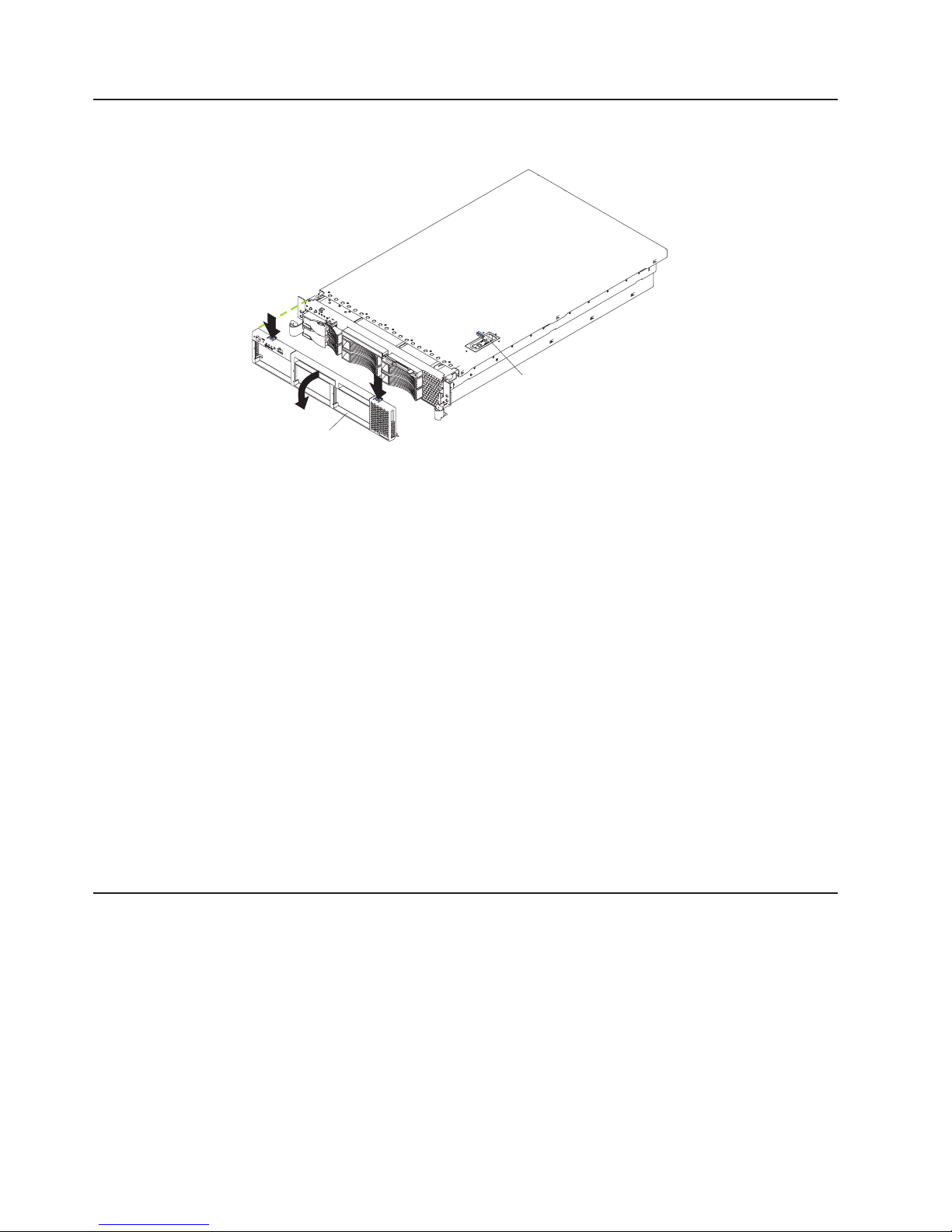
Removing the cover and bezel
The following illustration shows how to remove the cover and bezel.
Bezel
Complete the following steps to remove the server top cover:
1. Read the safety information beginning on page 125 and “System reliability
considerations” on page 41.
2. If you are planning to install or remove a microprocessor, memory-module, PCI
adapter, or battery, turn off the server and all attached devices, and disconnect
all external cables and power cords (see “Turning off the server” on page 6).
3. Press down on the left and right side latches and pull the server out of the rack
enclosure until both slide rails lock.
Cover-release latch
Note: Yo u can reach the cables on the back of the server when the server is in
the locked position.
4. Lift the cover-release latch. Lift the cover off the server and set the cover aside.
Attention: For proper cooling and airflow, replace the cover before turning on
the server. Operating the server for extended periods of time (over 30 minutes)
with the cover removed might damage server components.
Complete
1. Press in on the tabs on the top of the bezel, and rotate the bezel away from the
server front.
2. Store the bezel in a safe place.
Working with adapters
The following notes describe the types of adapters that your server supports and
other information that you must consider when installing adapters:
Before you install an adapter, review the following information:
v Read the documentation that comes with your operating system.
v Locate the documentation that comes with the adapter and follow those
instructions in addition to the instructions in this chapter. If you need to change
the switch or jumper settings on your adapter, follow the instructions that come
with the adapter.
v Yo u can install only low-profile adapters in slots 1 and 2.
the following steps to remove the bezel:
48 xSeries 345 Type 8670: Hardware Maintenance Manual and Troubleshooting Guide
Page 57

v Yo u can install standard full-length adapters, with the adapter guides removed
from the adapters, in slots 3 and 4.
v Yo u can install only a half-length adapter in slot 5.
v A ServeRAID-5i adapter can be installed only in PCI slot 2. The low-profile 2-U
bracket that comes with the controller is required to install the controller.
v The optional IBM Remote Supervisor Adapter can be installed only in PCI slot 5.
Use the ribbon cable that comes with the adapter to connect the adapter to the
system management connector on the PCI riser card.
v Your server supports 5.0 V and universal PCI adapters on the 32-bit PCI slot 5;
your server supports only 3.3 V and universal PCI adapters in the 64-bit
PCI/PCI-X slot 3 and 4.
v The PCI bus configuration is:
– Non-hot-plug, 64-bit PCI-X slots 1 and 2 (PCI bus A, 100 MHz)
– Non-hot-plug, 64-bit PCI-X slots 3 and 4 (PCI bus B, 133 MHz)
– Non-hot-plug, 32-bit PCI slot 5 (PCI bus C, 33 MHz)
The server scans PCI and PCI-X slots 1 through 5 to assign system resources.
v
Then, the server starts (boots) the system devices in the following order, if you
have not changed the default boot precedence: integrated Ethernet controller,
integrated SCSI controller, and then PCI and PCI-X slots 5, 3, 4, 1, and 2.
Notes:
1. If a ServeRAID-5i adapter is installed, it takes control of the integrated SCSI
controller with RAID capabilities and operates at 66 MHz. A ServeRAID-5i
adapter can be installed only in slot 2.
2. To have SCSI capabilities if you remove the ServeRAID-5i adapter or other
RAID adapter, start the Configuration/Setup Utility program, and select
Devices and I/O Ports from the main menu to enable the SCSI controller
with RAID capabilities. See “Using the Configuration/Setup Utility program” on
page 11 for details about using the Configuration/Setup Utility program.
3. To change the startup (boot) precedence for PCI and PCI-X devices, start the
Configuration/Setup Utility program, and select Start Options from the main
menu. See “Using the Configuration/Setup Utility program” on page 11 for
details about using the Configuration/Setup Utility program.
Chapter 4. Customer replaceable units 49
Page 58
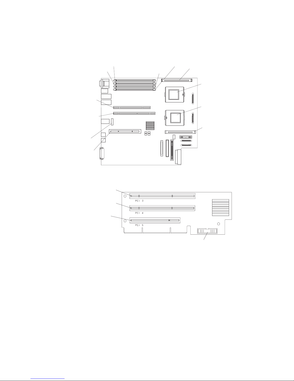
The following illustrations show the location of the PCI and PCI-X adapter
expansion slots on the system board and PCI riser card.
System board
PCI-X slot 1
64-bit 3.3V
100 MHz
(J14)
PCI-X slot 2
64-bit 3.3V
100 MHz
(J13)
Battery
(BH1)
PCI riser
card
(J16)
DIMM 2
(J2)
DIMM 1
(J1)
DIMM 3
(J3)
DIMM 4
(J4)
VRM 2
(J5)
Microprocessor 2
(J6)
Microprocessor 1
(J7)
VRM 1
(J8)
PCI riser card
PCI-X slot 3 64-bit
3.3V (PCI 3)133 MHz
PCI-X slot 4 64-bit
3.3V 133 MHz (PCI 4)
PCI slot 5 32-bit
5V 33 MHz (PCI 5)
System management connector
Complete the following steps to install a PCI or PCI-X adapter:
1. Read the safety information beginning on page 125 and “System reliability
considerations” on page 41.
2. Turn off the server and peripheral devices, and disconnect all power cords and
external cables (see “Turning off the server” on page 6); then, remove the
cover (see “Removing the cover and bezel” on page 48).
3. Determine which expansion slot you will use for the adapter.
50 xSeries 345 Type 8670: Hardware Maintenance Manual and Troubleshooting Guide
Page 59

4. If you are installing an adapter in PCI slot 3, 4, or 5, remove the PCI riser-card
assembly.
a. Lift the retention latch to release the PCI riser-card assembly.
b. Lift the assembly from the server.
c. Place the assembly on a flat, level surface.
PCI riser-card
assembly
Retention
latch
Guide tab
5. Open the adapter retainer, and slide the expansion-slot cover out of the server
or PCI riser-card assembly. Store it in a safe place for future use.
Attention: Expansion-slot covers must be installed on all empty slots. This
maintains the electronic emissions characteristics of the system and ensures
proper cooling of system components.
6. See the documentation that comes with your adapter for any cabling
instructions. It might be easier for you to route cables before you install the
adapter.
7. Remove the adapter from the static-protective package.
Attention: Avoid touching the components and gold-edge connectors on the
adapter.
Chapter 4. Customer replaceable units 51
Page 60

8. Install the adapter:
a. If you are installing a full-length adapter, remove the blue adapter guide (if
any) from the end of the adapter.
Adapter guide
b. Carefully grasp the adapter by its top edge or upper corners, and align it
with the expansion slot.
c. Press the adapter firmly into the expansion slot, and close the adapter
retainer.
Attention: When you install an adapter in the server, be sure that it is
completely and correctly seated in the connector. Incomplete insertion
might cause damage to the system board or the adapter.
The following illustration shows how to install a PCI or PCI-X adapter in
slots 1 and 2.
52 xSeries 345 Type 8670: Hardware Maintenance Manual and Troubleshooting Guide
Page 61
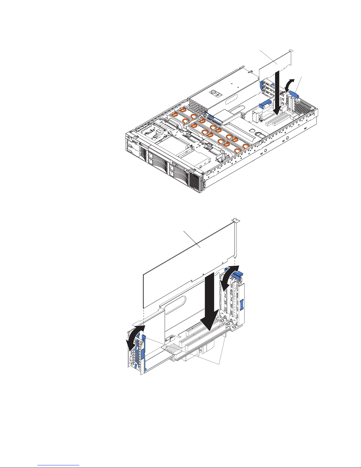
Low-profile
PCI adapter
Adapter
retainer
1
P
O
S
2
W
U
E
P
R
P
L
L
i
V
g
D
IE
R
h
ia
S
M
t
P
g
N
n
a
O
R
o
th
N
s
E
ti
D
c
U
OV
s
N
™
D
E
A
R
N
N
S
T
M
P
I
E
C
C
S
P
P
U
C
M
P
M
E
U
I
M
/V
S
M
O
R
DA
R
A
M
Y
T
S
C
D
H
A
B
P
C
BU
I
R
C
E
S
M
I
N
D
FA
N
T
E
M
P
The following illustration shows how to install a PCI or PCI-X adapter in
slots 3, 4, and 5.
PCI adapter
Adapter retainers
Chapter 4. Customer replaceable units 53
Page 62

9. If you removed the PCI riser-card assembly to install the adapter, press the
PCI riser-card assembly firmly into the connector, and close the retention latch.
PCI riser-card
assembly
Retention
latch
Note: Make sure that the PCI riser-card assembly is properly seated on the
system-board connector and that the cables under the PCI riser-card assembly
are not pinched.
10. Connect any needed cables to the adapter. See the documentation that comes
with your adapter for cabling instructions.
Attention:
v When you route the cables, do not block the ventilated space around any of
the fans. In addition, route any cables that are plugged into the PCI adapter
under adjacent adapters so they are not pinched between the top edge of
the adapter and the shuttle side wall.
v To ensure system reliability, an optional SCSI adapter cannot control internal
hard disk drives.
you have other options to install or remove, do so now. Otherwise, go to
If
“Installing the server cover and bezel” on page 71.
Installing a ServeRAID-5i adapter
The following notes describe the ServeRAID-5i adapter and other information that
you must consider when installing the ServeRAID-5i controller:
v Yo u can install an optional RAID adapter in your server to control the internal
hot-swap hard disk drives, for example, to enable you to configure the internal
hot-swap hard disk drives into disk arrays. You can also cable a RAID adapter to
external hard disk drives. See your RAID adapter option documentation for
complete instructions to install a RAID adapter in your server and for additional
information about RAID controllers.
v No rerouting of the internal SCSI cable is required if you are installing the
ServeRAID-5i adapter. The ServeRAID-5i adapter uses the SCSI connector on
the system board for output.
54 xSeries 345 Type 8670: Hardware Maintenance Manual and Troubleshooting Guide
Page 63

v The ServeRAID-5i adapter can be installed only in PCI-X slot 2. Slot 2 is the only
PCI-X slot that supports the ServeRAID-5i adapter requirements.
v Connections made to external SCSI devices will be asynchronous.
v To have SCSI capabilities if you remove the ServeRAID-5i adapter or other RAID
adapter, start the Configuration/Setup Utility program, and select Devices and
I/O Ports from the main menu to enable the SCSI controller with RAID
capabilities. See “Using the Configuration/Setup Utility program” on page 11 for
details about using the Configuration/Setup Utility program.
Complete the following steps to install a ServeRAID-5i controller:
1. Read the safety information beginning on page 125 and “System reliability
considerations” on page 41.
2. Turn off the server and peripheral devices, and disconnect all power cords and
external cables (see “Turning off the server” on page 6); then, remove the cover
(see “Removing the cover and bezel” on page 48).
3. Open the adapter retainer, and slide the slot 2 expansion-slot cover out of the
server. Store it in a safe place for future use.
Attention: Expansion-slot covers must be installed on all empty slots. This
maintains the electronic emissions characteristics of the system and ensures
proper cooling of system components.
4. Install the low-profile 2-U bracket on the adapter:
a. Remove the adapter from the static-protective package. Set the adapter
down on a nonconductive, static-protected surface (place it component side
up).
Attention: Avoid touching the components and gold-edge connectors on
the adapter.
b. Remove the 3-U bracket from the adapter, and replace it with the 2-U low
profile bracket that comes with the RAID adapter option. See the
documentation that comes with your RAID adapter option for instructions.
Install the adapter:
5.
a. Carefully grasp the adapter by its top edge or upper corners, and align it
with the expansion slot on the system board.
b. Press the adapter firmly into the expansion slot, and close the adapter
retainer.
Attention: When you install an adapter in the server, be sure that it is
completely and correctly seated in the connector. Incomplete insertion might
cause damage to the system board or the adapter.
you have other options to install or remove, do so now. Otherwise, go to
If
“Installing the server cover and bezel” on page 71.
Installing a hot-swap drive
The following notes describe the type of hard disk drive that your server supports
and other information that you must consider when installing a hard disk drive:
v Your server supports six 1-inch (26 mm) slim 3.5-inch low-voltage differential
(LVD) hard disk drives.
v All hot-swap drives installed in the server should have the same throughput
speed rating. Mixing hard disk drives with different speed ratings will cause all
drives to operate at the lower throughput speed.
v The SCSI ID assigned to each bay is printed on the bezel.
Chapter 4. Customer replaceable units 55
Page 64

Complete the following steps to install a drive in a hot-swap bay.
Attention: To maintain proper system cooling, do not operate the server for more
than 10 minutes without either a drive or a filler panel installed in each bay.
1. Read the safety information beginning on page 125 and “System reliability
considerations” on page 41.
2. Remove the filler panel from one of the empty hot-swap bays by inserting your
finger into the depression at the left side of the filler panel and pulling it away
from the server.
3. Install the hard disk drive in the hot-swap bay:
a. Ensure that the tray handle is open (that is, perpendicular to the drive).
b. Align the drive assembly with the guide rails in the bay.
c. Gently push the drive assembly into the bay until the drive stops.
d. Push the tray handle to the closed (locked) position.
Drive-tray assembly
Drive handle
e. Check the hard disk drive status LED to verify that the hard disk drive is
operating properly.
If the amber hard disk drive status LED for a drive is lit continuously, that
individual drive is damaged and needs to be replaced. If the green hard disk
drive activity LED is flashing, the drive is being accessed.
If you have a RAID configuration on your server using the integrated
Note:
SCSI controller with RAID capabilities, or if your server has a RAID adapter
installed, you might need to reconfigure your disk arrays after installing hard
disk drives. See the RAID documentation on the IBM xSeries Documentation
CD for information about RAID adapters.
Memory technology transition
IBM xSeries 345 is making a transition from 128 Mb to 256 Mb memory technology
for 256 MB dual inline memory modules (DIMMs). To accommodate this transition,
additional xSeries models are now available. These new models come with two 256
MB capacity, 256 Mb technology DIMMs. The Chipkill™ feature that is supported
with the 256 MB capacity, 128 Mb technology DIMMs is not supported with the 256
Mb technology DIMMs. If you require DIMMs that support the Chipkill feature, a
limited supply of the 256 MB, 128 Mb technology DIMMs will be available for order.
In addition, IBM will continue to offer the Chipkill feature with DIMMs that have a
capacity of 512 MB or greater.
Filler panel
56 xSeries 345 Type 8670: Hardware Maintenance Manual and Troubleshooting Guide
Page 65

Installing memory modules
The following notes describe the types of dual inline memory modules (DIMMs) that
your server supports and other information that you must consider when installing
DIMMs:
v The system board contains four DIMM connectors and supports two-way memory
interleaving.
v The DIMM options available for your server are 256 MB, 512 MB, 1 GB, and 2
GB.
v The amount of usable memory will be reduced depending on the system
configuration. The BIOS will display the total amount of installed memory and the
amount of configured memory.
v Your server supports a minimum of two 256 MB DIMMs (for a total of 512 MB)
installed in the DIMM 1 and DIMM 2 memory connectors (J1 and J2,
respectively). When you install additional DIMMs, install them in pairs, with the
next pair in DIMM connectors 3 and 4 (J3 and J4).
v Both DIMMs in a pair must be the same size, speed, type, and technology. You
can mix compatible DIMMs from various manufacturers.
v The second pair of DIMMs do not have to be the same size, speed, type, and
technology as the first pair.
v Install only 2.5 V, 184-pin, double-data-rate (DDR), PC2100, registered
synchronous dynamic random-access memory (SDRAM) with error correcting
code (ECC) DIMMs. These DIMMs must be compatible with the latest PC2100
(and downward compatible with PC1600) SDRAM Registered DIMM
specification, which is available from http://www.jedec.org/ on the World Wide
Web. For a list of supported options for your server, go to http://www.ibm.com/
servers/eserver/serverproven/compat/us/
v Your server supports Chipkill technology if the DIMMs are all of the type 4x.
v Save new configuration information only if you replace a damaged DIMM that
was marked as Disabled in the Configuration/Setup Utility program Memory
Settings menu. In this case, re-enable the memory row in the
Configuration/Setup Utility program or reload the default memory settings. See
“Using the Configuration/Setup Utility program” on page 11 for more information.
v Before you begin, read the documentation that comes with your option.
v Install the DIMMs in the order shown in the following table:
on the World Wide Web.
Table 7. DIMM order of installation
Pair DIMM connectors
First 1 and 2 (J1, J2)
Second 3 and 4 (J3, J4)
Complete the following steps to install a DIMM:
1. Read the safety information beginning on page 125 and “System reliability
considerations” on page 41.
2. Turn off the server, and disconnect all power cords and external cables (see
“Turning off the server” on page 6); then, remove the server cover (see
“Removing the cover and bezel” on page 48).
3. Locate the DIMM connectors on the system board, and determine the
connectors into which you will install the DIMMs.
4. Touch the static-protective package that contains the DIMM option to any
unpainted metal surface on the server. Then, remove the DIMM from the
Chapter 4. Customer replaceable units 57
Page 66

package.
58 xSeries 345 Type 8670: Hardware Maintenance Manual and Troubleshooting Guide
Page 67

5. To install the DIMM, repeat the following steps for each DIMM that you install:
a. Turn the DIMM so that the DIMM keys align correctly with the connector on
the system board.
Attention: To avoid breaking the retaining clips or damaging the DIMM
connectors, handle the clips gently.
b. If closed, open the retaining clips; then, insert the DIMM by pressing the
DIMM straight into the connector. Be sure that the retaining clips snap into
the closed position.
DIMM 3 (J3)
DIMM 4 (J4)
DIMM 1 (J1)
DIMM 2 (J2)
Note: If a gap exists between the DIMM and the retaining clips, the DIMM
has not been properly installed. In this case, open the retaining clips and
remove the DIMM; then, reinsert the DIMM.
you have other options to install or remove, do so now. Otherwise, go to
If
“Installing the server cover and bezel” on page 71.
Installing a microprocessor
The following notes describe the type of microprocessor that your server supports
and other information that you must consider when installing a microprocessor:
v Your server supports up to two microprocessors. With two microprocessors, your
server can operate as a symmetric multiprocessing (SMP) server. With SMP,
certain operating systems and application programs can distribute the processing
load between the microprocessors. If your server comes with one
microprocessor, you can install a second microprocessor.
v Yo u might need to update the server BIOS code. Be sure to read the
documentation that comes with the microprocessor so that you can determine
whether you need to update the server BIOS code. You can download the latest
level of BIOS code and many other code updates for your server at
http://www.ibm.com/support on the World Wide Web.
v (Optional) Obtain an SMP-capable operating system. For a list of supported
operating systems and other options, go to http://www.ibm.com/servers/eserver/
serverproven/compat/us/ on the World Wide Web.
Chapter 4. Customer replaceable units 59
Page 68

v To order additional microprocessor options, contact your IBM reseller or IBM
marketing representative.
v When you install the microprocessor in socket J6, you must also install the
voltage regulator module (VRM) that comes with the microprocessor in VRM
connector J5.
v The microprocessor speeds are automatically set for this server; therefore, you
do not need to set any microprocessor frequency-selection jumpers or switches.
v If you need to replace a microprocessor, call for service.
v If your server supports a 400 MHz front-side bus, install only a microprocessor
with one pin missing from one corner and two pins missing from an adjacent
corner. If your server supports a 400 MHz front-side bus, the heat-sink retention
mechanism surrounding the microprocessor connector is metallic gray.
400 MHz front-side bus
microprocessor
533 MHz front-side bus
microprocessor
If your server supports a 533 MHz front-side bus, install only a microprocessor
with one pin missing from each of two adjacent corners. If your server supports a
533 MHz front-side bus, the heat-sink retention mechanism surrounding the
microprocessor connector is black.
v If the thermal-grease protective cover (for example, a plastic cap or tape liner) is
removed from the heat sink or fan sink, do not touch the thermal grease on the
bottom of the heat sink or fan sink or set down the heat sink or fan sink.
Note: Removing the heat sink or fan sink from the microprocessor destroys the
even distribution of the thermal grease and requires replacing the thermal
grease. Setting down the heat sink or fan sink onto any surface when the
thermal-grease protective cover is removed will contaminate the thermal grease.
If the thermal grease becomes contaminated with particles, it must be replaced.
For information about replacing contaminated thermal grease on the heat sink or
fan sink, contact IBM Integrated Technology Services. For the most up-to-date
phone numbers, go to http://www.ibm.com/planetwide/, or in the U.S. and
Canada, call 1-800-IBM-SERV (1-800-426-7378).
Have the following information ready when you call:
– Machine type and model
– Serial number of your server
v Do not remove the first microprocessor from the system board to install the
second microprocessor.
The following illustration is a simplified layout of the microprocessor connector
locations and other microprocessor-related components on the system board.
60 xSeries 345 Type 8670: Hardware Maintenance Manual and Troubleshooting Guide
Page 69

VRM 2 connector
(J5)
Microprocessor 2
(J6)
Microprocessor 1
(J7)
VRM 1 connector
(J8)
Note: For additional illustrations of the system-board components, see
“System-board option connectors” on page 44
Attention:
v A startup (boot) processor must always be installed in socket J7 on the system
board.
v To ensure proper server operation when you install an additional microprocessor,
use microprocessors that have the same cache size and type, and the same
clock speed. Microprocessor internal and external clock frequencies must be
identical.
Chapter 4. Customer replaceable units 61
Page 70

Complete the following steps to install an additional microprocessor:
1. Read the safety information beginning on page 125 and “System reliability
considerations” on page 41.
2. Turn off the server, and disconnect all power cords and external cables (see
“Turning off the server” on page 6); then, remove the server cover (see
“Removing the cover and bezel” on page 48).
3. Remove the air baffle covering the microprocessor section of the system board,
and set the air baffle aside.
4. Remove the air baffle from the empty microprocessor socket. Store it in a safe
place for future use. An empty microprocessor socket must contain an air baffle.
1
POWER
SUPPLIES
2
Light Path
VRM
Diagnostics™
NON
REDUNDANT
OVER SPEC
NMI
CPU
SP
CPU/VRM
MEMORY
MISMATCH
DASD
A
B
PCI
BUS
REMIND
C
FAN
TEMP
62 xSeries 345 Type 8670: Hardware Maintenance Manual and Troubleshooting Guide
Page 71

5. Install a VRM in the VRM connector (J5). See the illustration at the beginning of
these instructions for the location of the connectors:
a. Center the VRM over the connector. Make sure that the VRM is oriented
and aligned correctly.
b. Carefully but firmly push down the VRM to seat the VRM in the connector.
c. Insert one end of the retainer clip on the side of the connector, and fit the
retainer clip over the VRM. Insert the free end of the retainer clip on the
other side of the connector.
6. Locate the second microprocessor socket (connector J6) on the system board.
7. Install the microprocessor:
a. Touch the static-protective package containing the microprocessor to any
unpainted metal surface on the server. Then, remove the microprocessor
from the package.
b. Remove the protective cover, tape, or label from the surface of the
microprocessor socket, if present.
Attention: You must ensure that the locking lever on the microprocessor
socket is in the fully open position before you insert the microprocessor in
the socket. Failure to do so might result in permanent damage to the
microprocessor, microprocessor socket, and system board.
c. Rotate the locking lever on the microprocessor socket from its closed and
locked position until it stops or clicks in the fully open position
(approximately 135° angle).
Lever fully
Lever closed
open
Attention:
v Do not use excessive force when pressing the microprocessor into the
socket.
v Make sure that the microprocessor is oriented and aligned correctly with
pin number 1 in the socket before you try to close the lever.
Chapter 4. Customer replaceable units 63
Page 72

d. Center the microprocessor over the microprocessor socket. Align the triangle
on the corner of the microprocessor with the triangle on the corner of the
socket, and carefully press the microprocessor into the socket.
Microprocessor 2
Alignment marks
Microprocessor
socket 2
e. Carefully close the microprocessor-release lever to secure the
microprocessor in the socket.
Install a heat sink on the microprocessor:
8.
Attention:
v Do not set the heat sink down after you remove the plastic cover.
Thermal grease
Heat sink
v Do not touch the thermal grease on the bottom of the heat sink or set down
the heat sink. Any contact with the thermal grease will contaminate it. For
details, see the thermal grease information on page 60.
Remove the plastic protective cover from the bottom of the heat sink.
a.
b. Align and place the heat sink on top of the microprocessor with the thermal
grease side down. Press firmly on the heat sink.
Attention: If you do not alternate the tightening of the two captive screws,
you might damage the microprocessor. Ensure that the screws are
completely tightened; otherwise, the server will not function properly.
64 xSeries 345 Type 8670: Hardware Maintenance Manual and Troubleshooting Guide
Page 73

c. Alternate the tightening of the captive screws to secure the heat sink to the
microprocessor. Turn one screw a few turns and then turn the other screw a
few turns, alternating between the screws until the heat sink is secure.
Captive screws
Heat sink
Microprocessor
VRM
Microprocessor
release lever
9. Install the air baffle over the microprocessor section of the system board.
If you have other options to install or remove, do so now. Otherwise, go to
“Installing the server cover and bezel” on page 71.
Chapter 4. Customer replaceable units 65
Page 74
Installing a hot-swap power-supply
Your server supports a maximum of two hot-swap power supplies.
Statement 8
CAUTION:
Never remove the cover on a power supply or any part that has the following label
attached.
Hazardous voltage, current, and energy levels are present inside any component that
has this label attached. There are no serviceable parts inside these components. If you
suspect a problem with one of these parts, contact a service technician.
Complete the following steps to install a power supply:
1. Read the safety information beginning on page 125 and “System reliability
considerations” on page 41.
2. (Some models) Remove the power-supply blank from the empty power-supply
bay by pinching the side clip and pulling the power-supply blank from the bay.
Save the power-supply blank in case you remove the power supply at a later
time.
Attention: During normal operation, each power-supply bay must have either
a power supply or power-supply blank installed for proper cooling.
66 xSeries 345 Type 8670: Hardware Maintenance Manual and Troubleshooting Guide
Page 75

3. Install the power supply in the bay:
a. Move the handle on the power supply into the open position, pinch the side
clip, and slide the power supply into the chassis.
b. Gently close the handle to seat the power supply in the bay.
Power supply
Handle
(open position)
AC power
LED (green)
DC power
LED (green)
Power supply blank
(some models)
4. Plug the power cord for the new power supply into the power-cord connector on
the power supply.
The following illustration shows the power-supply connectors on the back of the
server.
Power supply 1
power cord connector
Power supply 2
power cord connector
5. Route the power cord through the cable-management arm. (See “Installing the
server in a rack” on page 71).
6. Plug the power cord into a properly grounded electrical outlet.
7. Verify that the dc power LED and ac power LED on the power supply are lit,
indicating that the power supply is operating correctly.
Chapter 4. Customer replaceable units 67
Page 76

Replacing a hot-swap fan
The following notes describe information that you must consider when installing a
hot-swap fan.
Attention: To ensure proper server operation, if a fan fails, replace it as soon as
possible.
v Your server supports a maximum of eight hot-swap fans.
v The following illustration shows the location of the hot-swap fans.
Fan 6
Fan 7
Fan 1
Fan 8
Fan 2
Fan 5
Fan 3
1
POWER
SUPPLIES
2
Light Path
VRM
Diagnostics™
NON
REDUNDANT
OVER SPEC
NMI
CPU
SP
CPU/VRM
MEMORY
MISMATCH
DASD
A
B
PCI
BUS
REMIND
C
FAN
TEMP
Fan 4
Fan LED
Complete the following steps to replace a hot-swap-fan:
1. Read the safety information beginning on page 125 and “System reliability
considerations” on page 41.
2. Remove the cover. See “Removing the cover and bezel” on page 48. The LED
on the failing fan assembly will be lit.
Attention: To ensure proper system cooling, do not remove the top cover for
more than 30 minutes during this procedure.
3. Place your fingers into the two handles on the top of the failing fan.
4. Press the handles and lift the fan out of the server.
5. Orient the new fan so the LED on top of the fan is to the right of the server.
6. Push the replacement fan assembly into the server until it clicks into place.
7. Replace the cover. See “Installing the server cover and bezel” on page 71.
68 xSeries 345 Type 8670: Hardware Maintenance Manual and Troubleshooting Guide
Page 77

Replacing the battery
The following notes describe information that you must consider when replacing the
battery:
v IBM has designed this product with your safety in mind. The lithium battery must
be handled correctly to avoid possible danger. If you replace the battery, you
must adhere to the following instructions.
Note: In the U. S., call 1-800-IBM-4333 for information about battery disposal.
v If you replace the original lithium battery with a heavy-metal battery or a battery
with heavy-metal components, be aware of the following environmental
consideration. Batteries and accumulators that contain heavy metals must not be
disposed of with normal domestic waste. They will be taken back free of charge
by the manufacturer, distributor, or representative, to be recycled or disposed of
in a proper manner.
v To order replacement batteries, call 1-800-772-2227 within the United States, and
1-800-465-7999 or 1-800-465-6666 within Canada. Outside the U.S. and
Canada, call your IBM reseller or IBM marketing representative.
Note: After you replace the battery, you must reconfigure your server and reset
the system date and time.
Statement 2
CAUTION:
When replacing the lithium battery, use only IBM Part Number 33F8354 or an
equivalent type battery recommended by the manufacturer. If your system has a
module containing a lithium battery, replace it only with the same module type made
by the same manufacturer. The battery contains lithium and can explode if not
properly used, handled, or disposed of.
Do not:
v Throw or immerse into water.
v Heat to more than 100° C (212° F)
v Repair or disassemble
Dispose
of the battery as required by local ordinances or regulations.
Complete the following steps to replace the battery:
1. Read the safety information beginning on page 125 and “System reliability
considerations” on page 41.
2. Follow any special handling and installation instructions supplied with the
battery.
3. Turn off the server and all attached devices, and disconnect all power cords
and external cables (see “Turning off the server” on page 6).
4. Remove the server cover (see “Removing the cover and bezel” on page 48).
5. Remove the adapters from PCI slots 1 and 2 (see “Working with adapters” on
page 48).
6. Disconnect any internal cables, as necessary.
7. Locate the battery (connector BH1) on the system board.
Chapter 4. Customer replaceable units 69
Page 78

Battery
(BH1)
8. Remove the battery:
a. Use one finger to press the top of the battery clip away from the battery.
b. Lift and remove the battery from the socket.
9. Insert the new battery:
a. Use one finger to press the top of the battery clip away from the battery.
b. Press the battery into the socket until it clicks into place. Make sure the
battery clip holds the battery securely.
10. Reinstall the adapters that you removed, and reconnect the internal cables that
you disconnected.
11. Connect all external cables and all power cords.
12. Reinstall the server cover (see “Installing the server cover and bezel” on page
71).
70 xSeries 345 Type 8670: Hardware Maintenance Manual and Troubleshooting Guide
Page 79

13. Start the Configuration/Setup Utility program, and set configuration parameters
as needed. See “Using the Configuration/Setup Utility program” on page 11 for
additional information about using the Configuration/Setup Utility program.
Completing the installation
To complete your installation, reinstall the bezel, reinstall the server cover,
reconnect all cables that you disconnected earlier, and for certain options, run the
Configuration/Setup Utility program. Follow the instructions in this section.
Attention:
v For proper cooling and airflow, replace the server cover before or shortly after
turning on the server. Operating the server for extended periods of time (over 30
minutes) with the server cover removed might damage server components.
v To ensure proper server operation, do not remove the air-baffle assembly from
the server except when installing or removing the components that are located
under the air baffle.
Installing the server cover and bezel
Complete the following steps to install the server cover and bezel:
1. Place the cover-release latch in the open (up) position.
2. Insert the bottom tabs of the top cover into the matching slots in the server
chassis.
3. Press down on the cover-release latch to lock the cover in place.
4. Align the hooks on the bottom of the bezel with the server.
5. Press the bezel toward the server until it clicks into place.
Installing the server in a rack
Detailed cabling instructions for a typical rack server configuration are in the Rack
Installation Instructions that come with your server.
Updating your server configuration
When you start your server for the first time after you add or remove an internal
option or an external SCSI device, you might see a message telling you that the
configuration has changed. The Configuration/Setup Utility program automatically
Cover-release latch
Bezel
Chapter 4. Customer replaceable units 71
Page 80

starts so that you can save the new configuration information. See “Using the
Configuration/Setup Utility program” on page 11 for more information about the
Configuration/Setup Utility program.
If a ServeRAID 5i adapter is installed in PCI slot 2, POST disables the integrated
SCSI controller. If you remove the ServeRAID 5i adapter from the server, the
integrated SCSI controller must be enabled manually through the
Configuration/Setup Utility program. Otherwise, the integrated SCSI controller will
remain disabled.
Some options have device drivers that you need to install. See the documentation
that comes with your option for information about installing any required device
drivers.
Your server comes with one or two microprocessors installed on the system board.
If your server comes with two microprocessors or if your server comes with one
microprocessor and you have installed an additional microprocessor, your server
can now operate as an SMP server. Therefore, you might need to upgrade your
operating system to support SMP. See the User’s Guide on the IBM xSeries
Documentation CD and your operating-system documentation for additional
information.
If you have a RAID configuration on your server using the integrated SCSI
controller or if your server has a RAID controller installed and you have installed or
removed a hard disk drive, you might need to reconfigure your disk arrays. See the
RAID documentation on the IBM xSeries Documentation CD for information about
reconfiguring your disk arrays.
Connecting external options
If you install a SCSI adapter or use the external SCSI connector, you can attach
external SCSI devices, such as a SCSI storage expansion enclosure, to your
server. You can attach additional external options to the other input/output (I/O)
connectors on the front and rear of your server. (See “Input/output ports” on page
73 for more information.)
Complete the following steps to attach an external device:
1. Read the safety information beginning on page 125 and “System reliability
considerations” on page 41. Also, read the documentation that comes with your
options.
2. Turn off the server and all attached devices (see “Turning off the server” on
page 6).
3. Follow the instructions that come with the option to prepare it for installation and
to connect it to the server.
If you are attaching an external SCSI device, see “Ultra320 SCSI controller
Note:
system-board connectors” on page 75 for information about SCSI cabling and SCSI
IDs.
72 xSeries 345 Type 8670: Hardware Maintenance Manual and Troubleshooting Guide
Page 81

Cabling the server
Notes:
1. Yo u must turn off the server (see “Turning off the server” on page 6) before
2. See the documentation that comes with your options for additional cabling
3. Cable identifiers are printed on the cables that come with your server and
The following illustrations show the locations of the input and output connectors on
your server.
Rear view
Serial
Video
connecting any cables to or disconnecting any cables from the server.
instructions. It might be easier for you to route cables before you install certain
options.
options. Use these identifiers to connect the cables to the correct connectors.
Mouse
Universal Serial Bus (USB)
1 and 2
Keyboard
Front view
Input/output ports
This section provides information about the I/O ports on the rear of your server.
These ports include the following:
v One video port
v One keyboard port
v One auxiliary-device port (pointing device) port
v One dual channel Ultra320 SCSI controller (LVD) SCSI port
v One serial port
v Three Universal Serial Bus (USB) version 1.1 ports (USB 1 and USB 2 on the
v Two Ethernet ports
v Two RS-485 communication ports dedicated to the integrated
Ethernet 1
Ethernet 2
USB 3
RS 485-A
(ISMP)
RS 485-B
(ISMP)
rear, USB 3 on the front)
system-management processor (ISMP)
SCSI
Chapter 4. Customer replaceable units 73
Page 82

Video port
Your server comes with an integrated super video graphics array (SVGA) video
controller. This controller is not removable, but you can disable it through the
Configuration/Setup Utility program or by installing a PCI video adapter.
Note: If you install a PCI video adapter, the server BIOS will automatically disable
the integrated video controller.
The following illustration shows the 15-pin analog video connector on the rear of
your server. This connector conforms to the industry standard.
5
1
1115
Keyboard port
There is one keyboard connector on the rear of your server.
Note: If you attach a standard (non-USB) keyboard to the keyboard connector, the
USB ports and devices will be disabled during the power-on self-test (POST).
The following illustration shows the keyboard connector on the rear of your server.
This connector conforms to the industry standard for a PS/2 keyboard.
6
4
2
5
3
1
Auxiliary-device (pointing device) port
The system board has one auxiliary-device port that supports a mouse or other
pointing device.
The following illustration shows the auxiliary-device connector on the rear of your
server. This connector conforms to the industry standard for a PS/2 pointing device.
6
4
2
5
3
1
74 xSeries 345 Type 8670: Hardware Maintenance Manual and Troubleshooting Guide
Page 83

Ultra320 SCSI controller system-board connectors
Your server has an integrated dual channel small computer system interface (SCSI)
controller with RAID capabilities. This controller supports two independent Ultra320
SCSI channels: one external and one internal. Each channel supports up to 15
SCSI devices. Yo u can use the external LVD SCSI channel connector on the rear of
your server to connect different types of SCSI devices, such as drives or printers.
This controller uses:
v Double-transition clocking to achieve up to 320 MB-per-second data-transfer
rates
v Domain name validation to negotiate compatible data-transfer speeds with each
device
v Cyclic redundancy checking (CRC), instead of the usual parity checking, to
improve data reliability
v An active terminator for SCSI bus termination
server comes with one SCSI cable, which connects the internal connector on
The
the system board to the standard hot-swap-drive backplane. If you plan to attach
external SCSI devices, you must order additional cables. To select and order the
correct cables for use with external devices, contact your IBM reseller or IBM
marketing representative.
SCSI cabling requirements
For information about the maximum length of SCSI cable, go to the American
National Standards Institute (ANSI) SCSI standards on the ANSI Web site at
http://www.ansi.org/ on the World Wide Web. Adhering to these standards will help
to ensure that your server operates properly.
SCSI IDs
Each SCSI device that is connected to a SCSI controller must have a unique SCSI
ID. This ID enables the SCSI controller to identify the device and ensure that
different devices on the same SCSI channel do not attempt to transfer data
simultaneously. SCSI devices that are connected to different SCSI channels can
have duplicate SCSI IDs. Table 8 lists the SCSI IDs for the hard disk drives and
backplanes that are connected to one channel.
Table 8. SCSI IDs for standard hot-swap hard disk drives, SCSI controller, and backplane
Device SCSI ID
Drive bay 1 0
Drive bay 2 1
Drive bay 3 2
Drive bay 4 3
Drive bay 5 4
Drive bay 6 5
SCSI controller 7
Backplane 8
The hot-swap-drive backplane controls the SCSI IDs for the internal hot-swap drive
bays. However, when you attach an external SCSI device to an optional SCSI
adapter, you must set a unique ID for the device. See the information that comes
with the device for instructions to set its SCSI ID.
Chapter 4. Customer replaceable units 75
Page 84

SCSI connectors
The following illustration shows a 68-pin, female D-shell SCSI connectors. These
connectors conform to the SCSI standard.
34
1
Serial port
68
35
Your server has one standard serial port. Some application programs require
specific ports, and some modems function properly only at certain communication
port addresses. Yo u might need to use the Configuration/Setup Utility program to
change communication port address assignments to prevent or resolve address
conflicts.
Viewing or changing the serial-port assignments
Complete the following steps to view or change the serial-port assignments:
1. Restart the server, and watch the monitor screen.
2. When the message Press F1 for Configuration/Setup appears, press F1.
3. From the main menu, select Devices and I/O Ports; then, press Enter.
Note: The Devices and I/O Ports choice appears only on the full configuration
menu. If you set two levels of passwords, you must type the administrator
password to access the full configuration menu.
4. Select the serial port; then, use the arrow keys to advance through the available
settings.
5. Select Save Settings; then, select Exit Setup to exit from the
Configuration/Setup Utility main menu.
Serial-port connector
The following illustration shows the 9-pin, male D-shell serial-port connector on the
rear of your server. This connector conforms to the industry standard.
1
69
5
Universal Serial Bus version 1.1 ports
Your server has one Universal Serial Bus (USB) version 1.1 connector on the front
of the server and two USB version 1.1 connectors on the rear of the server.
USB is a serial interface standard for telephony and multimedia devices. It uses
Plug and Play technology to determine the type of device that is attached to the
connector.
Notes:
1. If you attach a standard (non-USB) keyboard to the keyboard connector, the
USB ports and devices will be disabled during the power-on self-test (POST).
2. If you install a USB keyboard that has a mouse port, the USB keyboard
emulates a mouse, and you will not be able to disable the mouse settings in the
Configuration/Setup Utility program.
76 xSeries 345 Type 8670: Hardware Maintenance Manual and Troubleshooting Guide
Page 85

3. Check to make sure that your network operating system (NOS) supports USB
devices.
4. For additional information about USB version 1.1 devices, go to
http://www.usb.org/.
USB cables and hubs
You need a 4-pin cable to connect USB devices. If you plan to attach more than
three USB devices, you must use a hub to connect the devices. The hub provides
multiple connectors for attaching additional external USB devices.
USB technology provides up to 12 Mb-per-second (Mbps) speed with a maximum of
127 devices and a maximum cable length of five meters (16 ft).
USB-port connectors
Each USB port has an external connector on the front or rear of the server for
attaching USB-compatible devices.
The following illustration shows a USB-port connector. These connectors conform to
the USB version 1.1 standard.
14
Ethernet ports
Your server comes with an integrated dual-port Ethernet controller. This controller
provides an interface for connecting to 10-Mbps, 100-Mbps, or 1000-Mbps networks
and provides full-duplex capability, which enables simultaneous transmission and
reception of data on the Ethernet LAN.
To access the Ethernet controller, connect a Category 5, or higher, unshielded
twisted-pair (UTP) cable to either of the Ethernet (RS-45) connectors on the rear of
your server. See “System-board external port connectors” on page 45.
There are two RS-45 Ethernet connectors on the back of the server. See
“System-board external port connectors” on page 45 for the location of these
connectors.
8
1
Integrated system-management ports
The RS-485 connectors are used for the ISMP interconnect function. The ISMP
interconnect function uses these connectors to daisy-chain several system service
processors together. This function enables the service processors to communicate
with each other in half-duplex mode.
Chapter 4. Customer replaceable units 77
Page 86

78 xSeries 345 Type 8670: Hardware Maintenance Manual and Troubleshooting Guide
Page 87

Chapter 5. Field replaceable units
The following information describes procedures for removing and installing certain
components inside the server. Only a qualified service technician is authorized to
access the components described in this section.
Important: The field-replaceable unit (FRU) procedures are intended for trained
servicers who are familiar with IBM xSeries products. See the parts listing in
“System” on page 116 to determine if the component being replaced is a
customer-replaceable unit (CRU) or a FRU.
Hard disk drive backplane
This section contains instructions for removing and replacing the hard disk drive
backplane.
Before you begin:
v Read “Before you begin” on page 41.
v Read the safety notices in “Safety notices (multilingual translations)” on page
128.
v Read “Handling static-sensitive devices” on page 42.
Complete
the following steps to remove the hard disk drive backplane:
1. Turn off the server and any attached devices.
2. Disconnect external cables and option cables from the back of the server.
3. Remove the hard disk drives.
4. Remove the server cover (see “Removing the cover and bezel” on page 48).
5. Disconnect the two cables from the diagnostics/operator panel card.
6. Disconnect the hard disk drive cable from the backplane.
7. Disconnect the two cables from the back of the CD-ROM drive.
8. Press on the two backplane release tabs, and remove the backplane from the
server.
1
POWER
SUPPLIES
2
Light Path
VRM
Diagnostics™
NON
REDUNDANT
OVER SPEC
NMI
CPU
SP
CPU/VRM
MEMORY
MISMATCH
DASD
A
B
PCI
BUS
REMIND
C
FAN
TEMP
Hard disk drive
backplane
© Copyright IBM Corp. 2004 79
Page 88

9. Disconnect the power cable from the backplane.
To replace the hard disk drive backplane, reverse the previous steps.
Note: When reinstalling the hard disk drive backplane, engage the left-most tab
first.
Diagnostics/operator panel card
This section contains instructions for removing and replacing the
diagnostics/operator panel card.
Before you begin:
v Read “Before you begin” on page 41.
v Read the safety notices in “Safety notices (multilingual translations)” on page
128.
v Read “Handling static-sensitive devices” on page 42.
Complete
the following steps to remove the diagnostics/operator panel card:
1. Turn off the server and any attached devices.
2. Disconnect external cables and option cables from the back of the server.
3. Remove the server cover (see “Removing the cover and bezel” on page 48).
4. Disconnect the three cables from the card.
5. Remove the two screws from the card.
6. Remove the diagnostics/operator panel card from the server.
1
P
POWER
O
S
SUPPLIES
2
W
U
E
P
R
P
L
Light Path
L
ig
V
VRM
D
Diagnostics™
IE
R
i
S
M
a
g
N
NON
n
O
R
REDUNDANT
N
E
D
U
OV
OVER SPEC
N
D
E
A
R
N
S
N
NMI
T
M
P
I
E
C
C
CPU
SPSP
P
U
C
CPU/VRM
ME
MEMORY
P
M
MISMATCH
U
IS
M
/V
M
OR
R
DA
DASD
A
M
Y
T
S
C
D
H
A
B
P
PCI
C
BU
BUS
I
C
S
FANFAN
T
TEMP
E
M
P
Diagnostics/operator
panel card
h
t P
a
o
th
s
tic
s
™
R
REMIND
E
M
IN
D
To replace the diagnostics/operator panel card, reverse the previous steps.
80 xSeries 345 Type 8670: Hardware Maintenance Manual and Troubleshooting Guide
Page 89

Power-supply cage
This section contains instructions for removing and replacing the power-supply
cage.
Before you begin:
v Read “Before you begin” on page 41.
v Read the safety notices in “Safety notices (multilingual translations)” on page
128.
v Read “Handling static-sensitive devices” on page 42.
Complete
the following steps to remove the power-supply cage:
1. Turn off the server and any attached devices.
2. Disconnect external cables and option cables from the back of the server.
3. Remove the server cover (see “Removing the cover and bezel” on page 48).
4. Remove the air baffle.
5. Disconnect the four power-supply cage cables.
Note: To disconnect the powr cable to the hard disk drive backplane, partially
remove the hard disk drive backplane. (See “Hard disk drive backplane” on
page 79..)
6. Remove the three screws from the power-supply cage.
Power
supply cage
Air baffle
Raised tabs
7. Remove the power-supply cage from the server.
To replace the power-supply cage, reverse the previous steps.
Note: Tilt the power-supply cage during installation so that you insert the rear of
the cage first.
1
P
POWER
O
S
SUPPLIES
2
W
U
E
P
R
P
L
Light Path
L
i
V
VRM
g
D
Diagnostics™
IE
R
h
i
S
M
a
t
g
P
N
NON
n
a
O
R
REDUNDANT
o
t
N
h
s
E
t
D
i
c
U
OV
OVER SPEC
s
N
™
D
E
A
R
N
S
N
NMI
T
M
P
I
E
C
C
CPU
SPSP
P
U
C
CPU/VRM
M
P
MISMATCH
M
EM
U
IS
/V
M
OR
R
DA
DASD
A
M
YMEMORY
T
S
C
D
H
A
B
P
PCI
C
BUS
BU
I
R
REMIND
C
E
S
M
IN
D
FANFAN
T
TEMP
E
M
P
Chapter 5. Field replaceable units 81
Page 90
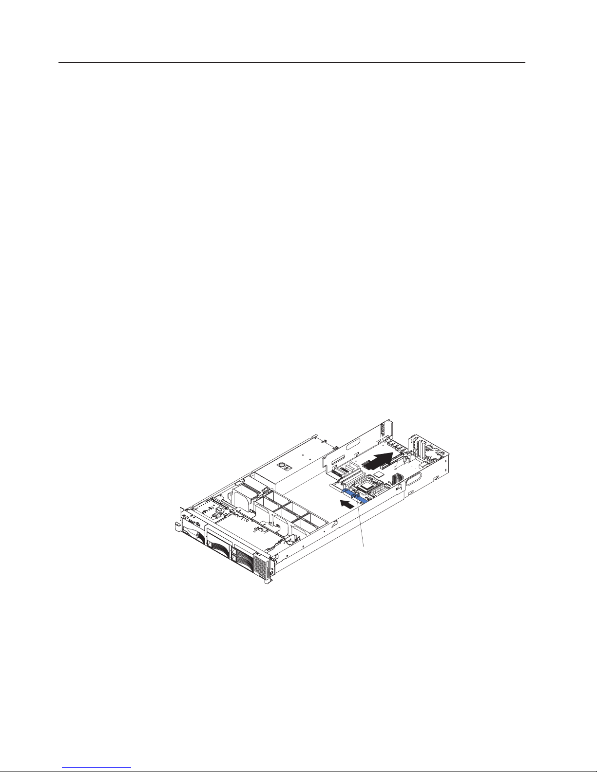
System-board shuttle
This section contains instructions for removng and replacing the system-board
shuttle.
Before you begin:
v Read “Before you begin” on page 41.
v Read the safety notices in “Safety notices (multilingual translations)” on page
128.
v Read “Handling static-sensitive devices” on page 42.
Complete
the following steps to remove the system-board shuttle:
1. Turn off the server and any attached devices.
Note: When replacing the system board, you must either update the server
with the latest firmware or restore the pre-existing firmware that the customer
provides on a diskette or CD image.
2. Disconnect external cables and option cables from the back of the server.
3. Remove the cover (see “Removing the cover and bezel” on page 48).
4. Disconnect and remove adapters (see “Working with adapters” on page 48).
5. Disconnect all cables from the system board.
6. Remove all microprocessors and VRMs, and set them aside on a
static-protected surface for reinstallation (see “Installing a microprocessor” on
page 59).
7. Remove the memory modules, and set them aside on a static-protected surface
for reinstallation (see “Installing memory modules” on page 57).
8. Release the shuttle locking latch, and remove the shuttle from the server.
N
M
S
P
C
P
M
U
IS
/
V
M
R
A
M
T
C
H
To replace the system board shuttle, slide the shuttle into the server and close the
shuttle locking latch. Reverse steps 4 through 7 to replace the components that
were removed.
82 xSeries 345 Type 8670: Hardware Maintenance Manual and Troubleshooting Guide
1
P
O
S
2
W
U
E
P
R
P
L
L
i
V
g
D
I
E
R
h
i
S
M
a
t
g
P
N
n
a
O
R
o
t
N
h
s
E
t
D
i
c
U
OV
s
N
™
D
E
A
R
N
S
T
P
I
E
C
C
P
U
M
E
M
O
DA
R
Y
S
D
A
B
P
C
BU
I
R
C
E
S
M
IN
D
FA
N
T
E
M
P
Shuttle locking
latch
Page 91

Chapter 6. Symptom-to-FRU index
This index supports xSeries 345 servers.
Notes:
1. Check the configuration before you replace a FRU. Configuration problems can
cause false errors and symptoms.
2. For IBM devices not supported by this index, refer to the manual for that device.
3. Always start with “General checkout” on page 25.
The symptom-to-FRU index lists symptoms, errors, and the possible causes. The
most likely cause is listed first. Use this symptom-to-FRU index to help you decide
which FRUs to have available when servicing the system.
The first column of the two-column tables in this index lists error codes or
messages, and the second column lists one or more suggested actions or FRUs to
replace. Take the action (or replace the FRU) suggested first in the list of the
second column, then try the server again to see if the problem has been corrected.
Note: Try reseating a suspected component or reconnecting a cable before
replacing the component.
The POST BIOS code displays POST error codes and messages on the screen.
Beep symptoms
Beep symptoms are short tones or a series of short tones separated by pauses
(intervals without sound). See the examples in the following table.
Beeps Description
1-2-3
4 Four continuous beeps
One beep after successfully completing POST indicates the system is functioning
properly.
Note: See “System” on page 116 to determine which components a field service technician should replace.
Beep/symptom FRU/action
1-1-2
(Microprocessor register test failed)
1-1-3
(CMOS write/read test failed)
1-1-4
(BIOS EEPROM checksum failed)
v One beep
v A pause (or break)
v Two beeps
v A pause (or break)
v Three beeps
1. Optional microprocessor (if installed)
2. Microprocessor
3. System board
1. Battery
2. System board
1. Recover BIOS
2. System board
© Copyright IBM Corp. 2004 83
Page 92

Note: See “System” on page 116 to determine which components a field service technician should replace.
Beep/symptom FRU/action
1-2-1
System board
(Programmable Interval Timer failed)
1-2-2
System board
(DMA initialization failed)
1-2-3
System board
(DMA page register write/read failed)
1-2-4
(RAM refresh verification failed)
1-3-1
1. DIMM
2. System board
DIMM
(first 64K RAM test failed)
2-1-1
System board
(Secondary DMA register failed)
2-1-2
System board
(Primary DMA register failed)
2-1-3
System board
(Primary interrupt mask register
failed)
2-1-4
System board
(Secondary interrupt mask register
failed)
2-2-1
System board
(Interrupt vector loading failed)
2-2-2
(Keyboard controller failed)
2-2-3
(CMOS power failure and checksum
checks failed)
2-2-4
(CMOS configuration information
validation failed)
2-3-1
1. System board
2. Keyboard
1. Battery
2. System board
1. Battery
2. System board
System board
(Screen initialization failed)
2-3-2
System board
(Screen memory failed)
2-3-3
System board
(Screen retrace failed)
2-3-4
System board
(Search for video ROM failed)
2-4-1
System board
(Video failed; screen believed
operable)
3-1-1
System board
(Timer tick interrupt failed)
3-1-2
System board
(Interval timer channel 2 failed)
84 xSeries 345 Type 8670: Hardware Maintenance Manual and Troubleshooting Guide
Page 93

Note: See “System” on page 116 to determine which components a field service technician should replace.
Beep/symptom FRU/action
3-1-3
(RAM test failed above address
OFFFFH))
3-1-4
(Time-Of-Day clock failed)
3-2-1
1. DIMM
2. System board
1. Battery
2. System board
System board
(Serial port failed)
3-2-2
System board
(Parallel port failed)
3-2-3
(Math coprocessor test failed)
3-2-3
(Failure comparing CMOS memory
size against actual)
3-3-1
(Memory size mismatch occurred.)
3-3-2
(Critical SMBUS error occurred)
1. Microprocessor
2. System board
1. DIMM
2. Battery
1. DIMM
2. Battery
1. Disconnect the server power cord from outlet, wait 30 seconds, and
retry.
2. System board.
3. DIMMs.
4. Hard disk drive backplane.
5. Power supply.
6. Power cage assembly.
7. 12C Cable.
3-3-3
(No operational memory in system)
1. Install or reseat the memory modules, and then do a 3 boot reset.
(For more information on a 3 boot reset, see “Using the
Configuration/Setup Utility program” on page 11).
2. DIMMs.
3. Memory board.
4. System board.
4-4-4 (Optional system management
adapter not installed in slot 1 or not
functioning correctly)
1. Verify that the adapter is installed in slot 1.
2. Adapter.
3. System board.
Two short beeps
(Information only, the configuration
has changed)
Three short beeps
1. Run Diagnostics.
2. Run the Configuration/Setup Utility program.
1. DIMM
2. System board
One continuous beep
1. Microprocessor
2. Optional microprocessor (if installed)
3. System board
Repeating short beeps
1. Keyboard
2. System board
Chapter 6. Symptom-to-FRU index 85
Page 94

Note: See “System” on page 116 to determine which components a field service technician should replace.
Beep/symptom FRU/action
One long and one short beep
1. Video adapter (if installed)
2. System board
One long and two short beeps
1. Video adapter (if installed)
2. System board
One long and three short beeps
1. Monitor
2. Video adapter, if installed
3. System board
Two long and two short beeps Video adapter
No-beep symptoms
Note: See “System” on page 116 to determine which components a field service technician should replace.
No-beep symptom FRU/action
No beep and the system
operates correctly.
No beeps occur after
successfully completing POST
(the power-on status is disabled)
No ac power (power supply ac
LED is off)
No beep and no video See “Undetermined problems” on page 112.
System will not start (power
supply ac LED is on)
1. Check speaker cables.
2. Speaker.
3. System board.
1. Run the Configuration/Setup Utility program, and set the Start Options
Power-On Status to enable.
2. Check the speaker connection.
3. System board.
1. Check the power cord.
2. Power supply. (If two are installed, swap them to determine if one is
defective.)
3. Disconnect the ribbon cable from connector J25 on the system board. If the ac
power LED comes on, see “Undetermined problems” on page 112.
4. Power cage assembly.
See “Power-supply LED errors” on page 101.
Diagnostic panel system-error LED
The system-error LED is lit when an error is detected. If the system-error LED is lit,
remove the cover, and check the diagnostic panel LEDs. The following table is a
complete list of diagnostics panel LEDs followed by the FRU or action for correcting
the problem. The information in the table is valid only when the system-error LED is
lit.
Notes:
1. If a diagnostics panel LED is lit and the information LED panel system-error
LED is off, there is probably an LED problem. Run LED diagnostics.
2. To locate the LEDs on the system board, see “System-board LED locations” on
page 47.
3. Check the system-error log for additional information before replacing a FRU.
86 xSeries 345 Type 8670: Hardware Maintenance Manual and Troubleshooting Guide
Page 95

4. The DIMM error LEDs, microprocessor error LEDs, and VRM error LEDs turn
off when the system is turned off.
Note: See “System” on page 116 to determine which components a field service technician should replace.
Diagnostics panel LED FRU/action
All LEDs off
(System-error log is 75% full; clear
the log.)
FAN LED on (The LED next to the
failing fan is on.)
MEMORY LED on (The LED next
to the failing DIMM is on.)
CPU LED on (The LED next to the
failing CPU is on.)
PCI BUS LED on
VRM LED on (The LED next to the
failing VRM is on.)
DASD LED on (The LED located
next to the drive bay that the failing
drive is installed in is lit. Check the
amber drive LED for the failing hard
drive.)
ISMP LED (Integrated System
Management detects an internal
error.)
POWER SUPPLY 1 LED on
POWER SUPPLY 2 LED on
NONREDUNDANT LED on
NMI LED on
1. Check the system-error log for the error condition; then, clear the
system-error log when the problem is found.
2. PFA alert; check log for failure; clear PFA alert; remove ac power for at least
20 seconds, reconnect, then turn on the system.
3. Run Light Path Diagnostics.
1. Failing fan.
2. System board
1. Failing DIMM.
2. System board
1. Run the Configuration/Setup Utility program to verify that all
microprocessors have identical cache sizes, clock speeds and clock
frequencies.
2. Microprocessor 1 or 2.
3. System board.
1. Remove all PCI adapters from slots on affected bus (see
“System-board LED locations” on page 47 for bus information, see
“Working with adapters” on page 48).
2. System board.
1. Voltage regulator module indicated by the lit VRM LED
2. Microprocessor indicated by the microprocessor LED
1. Be sure the fans are operating correctly and the airflow is good.
2. If installed, reseat I2C cable between hard disk drive backplane and hard
disk drive I2C on the system board (J10).
3. Failing drive. SCSI channel A has failed. (This is the SCSI channel for the
hot-swap hard disk drives).
4. Hard disk drive backplane.
1. Update ISMP firmware with latest level code. Unplug ac power from
the server for at least 30 seconds, and then retry.
2. System board.
1. Check the dc good LED on power supply 1. If it is off, replace power
supply 1.
2. Power cage assembly.
1. Check the dc good LED on power supply 2. If it is off, replace power
supply 2.
2. Power cage assembly.
1. Check the PS1 and PS2 LEDs and replace any indicated power supply.
2. Install an additional power supply or remove optional devices from the
server.
1. Restart the server.
2. Check the system-error log.
Chapter 6. Symptom-to-FRU index 87
Page 96

Note: See “System” on page 116 to determine which components a field service technician should replace.
Diagnostics panel LED FRU/action
TEMPERATURE LED on
1. Ambient temperature must be within normal operating specifications.
See “Features and specifications” on page 3.
2. Ensure fans are operating correctly.
3. Ensure that both air baffles are installed.
4. Examine system-error log.
a. System over recommended temperature - Information LED panel
b. Hard disk drive over recommended temperature (DASD LED also on)
1) Overheating hard drive
2) Hard disk drive backplane
System over recommended temperature for CPU x (where x is 1 or 2)
c.
(CPU LED is also on)
1) Microprocessor x
2) System board
If the CPU LED on the diagnostics panel is also lit, one of the
5.
microprocessors has caused the error.
CPU/VRM MISMATCH LED on
1. Move the microprocessor in socket 1 to socket 2, and move the
microprocessor in socket 2 to socket 1.
2. Ensure that both microprocessors are of the same type, with the same core
frequency and the same L2 size.
3. Ensure that both VRMs are of the same type.
4. Ensure that both VRMs are supported in your server model.
5. If a microprocessor is missing from socket 1, install a microprocessor in
socket 1.
FAN LED on
1. Check individual fan LEDs.
2. Replace respective fan.
3. Fan cable.
4. System board.
5. Power cage assembly.
Diagnostic error codes
Note: In the following error codes, if XXX is 000, 195, or 197, do not replace a
FRU. The description for these error codes are:
000 The test passed.
195 The Esc key was pressed to stop the test.
197 Warning; a hardware failure might not have occurred.
all error codes, replace the FRU or take the action indicated.
For
88 xSeries 345 Type 8670: Hardware Maintenance Manual and Troubleshooting Guide
Page 97

Note: See “System” on page 116 to determine which components a field service technician should replace.
Error code/symptom FRU/action
001-XXX-000
System board
(Failed core tests)
001-XXX-001
System board
(Failed core tests)
001-250-000
System board
(Failed system board ECC)
001-250-001
System board
(Failed system board ECC)
005-XXX-000
System board
(Failed video test)
011-XXX-000
System board
(Failed COM1 serial port test)
011-XXX-001
System board
(Failed COM2 serial port test)
014-XXX-000
System board
(Failed parallel port test)
015-XXX-001
System board
(USB interface not found, board damaged)
015-XXX-015
(Failed USB external loopback test)
1. Make sure the parallel port is not disabled.
2. Run the USB external loopback test again.
3. System board.
015-XXX-198
(USB device connected during USB test)
1. Remove USB devices from USB1 and USB2.
2. Run the USB external loopback test again.
3. System board.
020-XXX-000
System board
(Failed PCI interface test)
020-XXX-001
(Failed hot-swap slot 1 PCI latch test)
020-XXX-002
(Failed Hot-swap slot 2 PCI latch test)
020-XXX-003
(Failed hot-swap slot 3 PCI latch test)
020-XXX-004
(Failed hot-swap slot 4 PCI latch test)
030-XXX-000
1. PCI hot-swap latch assembly
2. System board
1. PCI hot-swap latch assembly
2. System board
1. PCI hot-swap latch assembly
2. System board
1. PCI hot-swap latch assembly
2. System board
System board
(Failed internal SCSI interface test)
035-XXX-099(No adapters were found.) If adapter is installed re-check connection.
035-XXX-S99
(Failed RAID test on PCI slot S. S =
number of failing PCI slot. Check System
Error Log before replacing a FRU.)
035-XXX-SNN
1. Adapter
2. SCSI backplane
3. Cable
Hard disk drive with SCSI ID nn on RAID adapter in PCI slot s.
(Check System Error Log before replacing
a FRU. s = number of failing PCI slot, nn =
SCSI ID of failing fixed disk.)
Chapter 6. Symptom-to-FRU index 89
Page 98

Note: See “System” on page 116 to determine which components a field service technician should replace.
Error code/symptom FRU/action
035-253-S99
(RAID adapter initialization failure)
1. ServeRAID adapter in slot s is not configured properly. Obtain
the basic and extended configuration status, and see the
ServeRAID Hardware Maintenance Manual for more
information.
2. Cable.
3. SCSI backplane.
4. Adapter.
075-XXX-000
Power supply
(Failed power supply test)
089-XXX-001
(Failed microprocessor test)
089-XXX-002
(Failed optional microprocessor test)
166-198-000 System Management:
Aborted
(Unable to communicate with ASM. It may
be busy. Run the test again.)
1. VRM 1 for microprocessor 1
2. Microprocessor 1
1. VRM 2 for optional microprocessor 2
2. Optional microprocessor 2
1. Run the diagnostic test again.
2. Correct other error conditions and retry. These include other failed
system-management tests and items logged in the system-error log
of the optional Remote Supervisor Adapter.
3. Disconnect all server and option power cords from the server, wait
30 seconds, reconnect, and retry.
4. Remote Supervisor Adapter, if installed.
5. System board.
166-201-001 System Management: Failed
(I2C bus error(s) See SERVPROC and
DIAGS entries in event log.)
1. If installed, reseat the I2C cable between the Remote
Supervisor Adapter (in PCI slot 5/J5 on the PCI riser card) and
system management connector on the PCI riser card.
2. Reseat memory DIMMs.
3. Memory DIMMs.
4. System board.
166-201-002 System Management: Failed
(I2C bus error(s) See SERVPROC and
DIAGS entries in event log.)
1. Reseat I2C cable between the operator information panel and
the system board (J22).
2. Diagnostics panel.
3. System board.
166-201-003 System Management: Failed
(I2C bus error(s) See SERVPROC and
DIAGS entries in event log.)
1. Reseat cables between the system board and the power supply
or power cage assembly.
2. Power cage assembly.
3. System board.
166-201-004 System Management: Failed
(I2C bus error(s) See SERVPROC and
DIAGS entries in event log.)
166-201-005 System Management: Failed
(I2C bus error(s) See SERVPROC and
DIAGS entries in event log.)
1. Hard disk drive backplane
2. System board
1. Reseat Memory DIMMs.
2. Reseat microprocessors.
3. Memory DIMMs.
4. Microprocessors.
5. System board.
90 xSeries 345 Type 8670: Hardware Maintenance Manual and Troubleshooting Guide
Page 99

Note: See “System” on page 116 to determine which components a field service technician should replace.
Error code/symptom FRU/action
166-250-000 System Management: Failed
(I2C cable is disconnected. Reconnect I2C
cable between Remote Supervisor Adapter
and system board.)
1. If installed, reseat the I2C cable between the Remote
Supervisor Adapter (in PCI slot 5/J5 on the PCI riser card) and
system-management connector on the PCI riser card.
2. I2C cables.
3. Advanced System Management adapter.
4. System board.
166-260-000 System Management: Failed
(Restart ASM Error. After restarting, ASM
communication was lost. Unplug and cold
boot to reset ASM.)
1. Disconnect all server and option power cords from the server,
wait 30 seconds, reconnect, and retry.
2. Reseat the Remote Supervisor Adapter in PCI slot 5/J5 on the PCI
riser card.
3. Remote Supervisor Adapter.
166-342-000 System Management: Failed
(ASM adapter BIST indicate failed tests.)
1. Ensure the latest firmware levels for Remote Supervisor
Adapter and BIOS.
2. Disconnect all server and option power cords from server, wait 30
seconds, reconnect, and retry.
3. Remote Supervisor Adapter.
166-400-000 System Management: Failed
(ISMP self test result failed tests: x where x
= Flash, RAM, or ROM.)
1. Reflash or update firmware for ISMP.
2. System board.
180-XXX-000 (Diagnostics LED failure) Run diagnostics panel LED test for the failing LED.
180-XXX-001
(Failed front LED panel test)
180-XXX-002
(Failed diagnostics LED panel test)
180-361-003
(Failed fan LED test)
180-XXX-003
1. Operator information panel
2. System board
1. Diagnostics panel
2. System board
1. Fan(s)
2. System board
System board
(Failed system board LED test)
180-XXX-005
(Failed SCSI backplane LED test)
1. SCSI backplane
2. SCSI backplane cable
3. System board
201-XXX-0NN
(Failed memory test.)
1. DIMM Location slots 1-6 where nn = DIMM location.
Note: nn 1=DIMM 1; 2=DIMM 2; 3=DIMM 3; 4=DIMM 4.
2. System board
201-XXX-999
(Multiple DIMM failure, see error text)
202-XXX-001
(Failed system cache test)
202-XXX-002
(Failed system cache test)
1. See error text for failing DIMMs.
2. System board.
1. VRM 1
2. Microprocessor 1
1. VRM 2
2. Microprocessor 2
Chapter 6. Symptom-to-FRU index 91
Page 100

Note: See “System” on page 116 to determine which components a field service technician should replace.
Error code/symptom FRU/action
206-XXX-000
(Failed diskette drive test)
1. Rerun the test with a different diskette.
2. Cable.
3. Diskette drive.
4. System board.
215-XXX-000
(Failed IDE CD-ROM drive test)
1. Rerun the test with a different CD-ROM.
2. CD-ROM drive cables.
3. CD-ROM drive.
4. System board.
217-198-XXX
(Could not establish drive parameters)
1. Check cable and termination.
2. SCSI backplane.
3. Hard disk.
217-XXX-000
Hard disk 1
(Failed BIOS hard disk test)
Note: If RAID is configured, the hard disk
number refers to the RAID logical array.
217-XXX-001
Hard disk 2
(Failed BIOS hard disk test)
Note: If RAID is configured, the hard disk
number refers to the RAID logical array.
217-XXX-002
Hard disk 3
(Failed BIOS hard disk test)
Note: If RAID is configured, the hard disk
number refers to the RAID logical array.
217-XXX-003
Hard disk 4
(Failed BIOS hard disk test)
Note: If RAID is configured, the hard disk
number refers to the RAID logical array.
217-XXX-004
Hard disk 5
(Failed BIOS hard disk test)
Note: If RAID is configured, the hard disk
number refers to the RAID logical array.
217-XXX-005
Hard disk 6
(Failed BIOS hard disk test)
Note: If RAID is configured, the hard disk
number refers to the RAID logical array
264-XXX-0NN
(Failed tape drive test)
1. Tape cartridge, if user executed the Read/Write Tape Drive test
(failure code of XXX = 256)
2. SCSI or power cable connected to tape drive with SCSI ID nn
3. Tape drive with SCSI ID nn (refer to the Help and Service
Information appendix of the tape drive User Guide)
4. System board or SCSI controller (run SCSI controller diagnostic to
determine if the SCSI bus is functioning properly.)
264-XXX-999
(Errors on multiple tape drives, see error
See error messages/text in the PC Doctor error log for detailed
information on each individual tape drive error.
text for more info)
301-XXX-000
Keyboard
(Failed keyboard test)
92 xSeries 345 Type 8670: Hardware Maintenance Manual and Troubleshooting Guide
 Loading...