

Page 1

LCM
NetBAY Advanced Connectivity Technology
Local Console Manager
Installer and User Guide
For 32P1635, 1735-L04 and 32P1644
Page 2
INSTRUCTIONS
This symbol is intended to alert the user to the presence of important operating and
maintenance (servicing) instructions in the literature accompanying the appliance.
DANGEROUS VOLTAGE
This symbol is intended to alert the user to the presence of uninsulated
dangerous voltage within the product’s enclosure that may be of sufficient
magnitude to constitute a risk of electric shock to persons.
POWER ON
This symbol indicates the principal on/off switch is in the on position.
POWER OFF
This symbol indicates the principal on/off switch is in the off position.
PROTECTIVE GROUNDING TERMINAL
This symbol indicates a terminal which must be connected to earth ground
prior to making any other connections to the equipment.
Page 3
Page 4
Statement 4:
DANGER
Electrical current from power, telephone, and communication cables is
hazardous.
To avoid a shock hazard:
•Do not connect or disconnect any cables or perform installation,
maintenance, or reconfiguration of this product during an electrical
storm.
•Connect all power cords to a properly wired and grounded electrical
outlet.
•Connect to properly wired outlets any equipment that will be attached
to this product.
•When possible, use one hand only to connect or disconnect signal
cables.
•Never turn on any equipment when there is evidence of fire, water, or
structural damage.
•Disconnect the attached power cords, telecommunications systems,
networks, and modems before you open the device covers, unless
instructed otherwise in the installation and configuration procedures.
•Connect and disconnect cables as described in the following table
when installing, moving, or opening covers on this product or
attached devices.
To Connect: To Disconnect:
1. Turn everything OFF.
2. First, attach all cables to devices.
3. Attach signal cables to connectors.
4. Attach power cords to outlet.
5. Turn device ON.
1. Turn everything OFF.
2. First, remove power cords from outlet.
3. Remove signal cables from connectors.
4. Remove all cables from devices.
Page 5

LCM
Installer and User Guide
Page 6

Page 7

Table of Contents
Chapter 1: Product Overview
Features and Benefits . . . . . . . . . . . . . . . . . . . . . . . . . . . . . 3
Safety Precautions . . . . . . . . . . . . . . . . . . . . . . . . . . . . . . .4
Chapter 2: Installation
Getting Started . . . . . . . . . . . . . . . . . . . . . . . . . . . . . . . . . .9
Installing Your LCM . . . . . . . . . . . . . . . . . . . . . . . . . . . . .9
Cabling the LCM . . . . . . . . . . . . . . . . . . . . . . . . . . . . . . .12
Chapter 3: Basic Operations
Controlling Your System . . . . . . . . . . . . . . . . . . . . . . . . .21
Viewing and Selecting Ports and Servers . . . . . . . . . . . .21
Configuring OSCAR . . . . . . . . . . . . . . . . . . . . . . . . . . . .24
Resetting Your Keyboard and Mouse . . . . . . . . . . . . . . 32
Displaying Version Information . . . . . . . . . . . . . . . . . . .33
Scanning Your System . . . . . . . . . . . . . . . . . . . . . . . . . . 34
Broadcasting to Servers . . . . . . . . . . . . . . . . . . . . . . . . . . 36
Appendices
Appendix A: FLASH Upgrades . . . . . . . . . . . . . . . . . . . . 41
Appendix B: Technical Specifications . . . . . . . . . . . . . .45
Appendix C: Hardware Maintenance Information . . . . 46
Appendix D: Notices . . . . . . . . . . . . . . . . . . . . . . . . . . . .47
Page 8

Page 9

1
Product Overview
Contents
Features and Benefits . . . . . . . . . . . . . . . . . . . . . . . . . . . .3
Safety Precautions . . . . . . . . . . . . . . . . . . . . . . . . . . . . . . .4
Page 10

Page 11
Chapter 1: Product Overview 3
Chapter 1: Product Overview
Features and Benefits
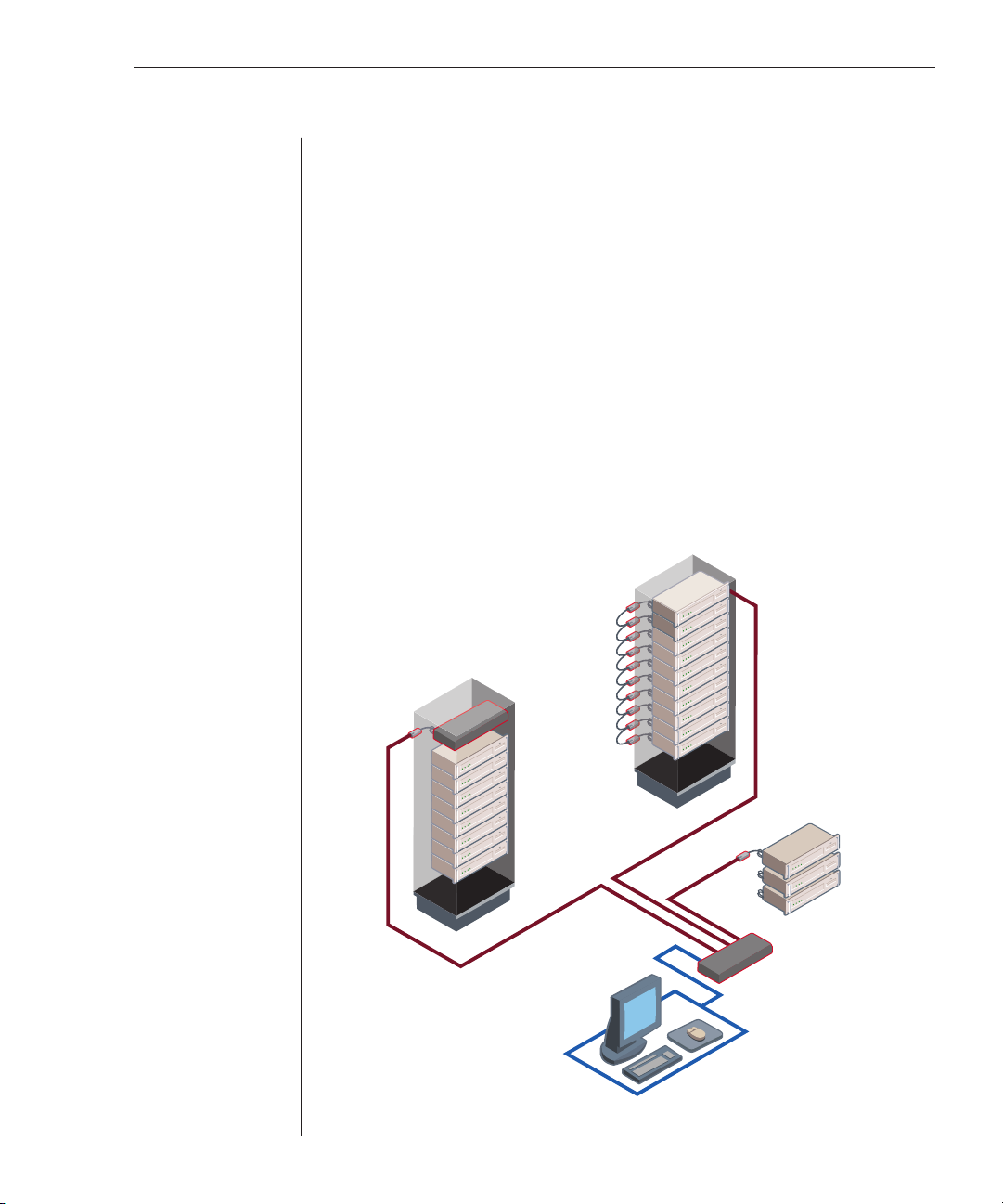
The IBM® NetBAY™ Local Console Manager (LCM) provides flexible, centralized
control of data center servers. The LCM consists of a rack mountable switch, with
four Analog Rack Interface (ARI) ports for connecting servers, that operates over
standard LAN connections. You access servers through an analog port with
enhanced video quality of up to 1600 x 1280 with an end-to-end cable length of up to
15 meters (49.2 feet). This solution delivers a significant reduction of cable volume.
The KVM Conversion Option (KCO), USB Conversion Option (UCO) and C2T
Conversion Option (CCO) intelligent cables (generically called CO cables)
with CAT 5 design dramatically reduce cable clutter, while providing optimal
digital display resolution and video settings. The built-in memory of the CO
simplifies configuration by assigning and retaining unique server identification
codes for each attached server. This integrated intelligence enhances security
and prevents unauthorized access to a server through cable manipulation.
The CO cable is powered directly from the server and provides Keep Alive
functionality even if the LCM is not powered.
KCO Cables
Switch
KCO Cables
Rack of
Servers
Figure 1.1: Example LCM Configuration
Rack of
Servers
CCO
Cable
LCM
Analog Connection
Chained C2T
Servers
Page 12

4 LCM Installer and User Guide
Safety Precautions
To avoid potential video and/or keyboard problems when using IBM products:
• If the building has 3-phase AC power, ensure that the computer and monitor
are on the same phase. For best results, they should be on the same circuit.
• Use only IBM-supplied cable to connect computers and KVM switches. IBM
warranties do not apply to damage resulting from user-supplied cable.
To avoid potentially fatal shock hazard and possible damage to equipment,
please observe the following precautions:
• Do not use a 2-wire extension cord in any IBM product confi guration.
• Te st AC outlets at the computer and monitor for proper polarity and grounding.
• Use only with grounded outlets at both the computer and monitor. When
using a backup uninterruptible power supply, power the computer, the
monitor and the LCM off the supply.
NOTE: The AC inlet is the main disconnect.
Rack mount safety considerations
• Elevated Ambient Temperature: If installed in a closed rack assembly, the
operation temperature of the rack environment may be greater than room
ambient. Use care not to exceed the rated maximum ambient temperature
of the unit.
• Reduced Air Flow: Installation of the equipment in a rack should be such
that the amount of airfl ow required for safe operation of the equipment is
not compromised.
• Mechanical Loading: Mounting of the equipment in the rack should be such
that a hazardous condition is not achieved due to uneven mechanical loading.
• Circuit Overloading: Consideration should be given to the connection of
the equipment to the supply circuit and the effect that overloading of
circuits might have on overcurrent protection and supply wiring. Consider
equipment nameplate ratings for maximum current.
• Reliable Earthing: Reliable earthing of rack mounted equipment should be
maintained. Pay particular attention to supply connections other than
direct connections to the branch circuit (for example, use of power strips).
Page 13
Chapter 1: Product Overview 5
Statement 4:
DANGER
Electrical current from power, telephone, and communication cables is
hazardous.
To avoid a shock hazard:
•Do not connect or disconnect any cables or perform installation,
maintenance, or reconfiguration of this product during an electrical
storm.
•Connect all power cords to a properly wired and grounded electrical
outlet.
•Connect to properly wired outlets any equipment that will be attached
to this product.
•When possible, use one hand only to connect or disconnect signal
cables.
•Never turn on any equipment when there is evidence of fire, water, or
structural damage.
•Disconnect the attached power cords, telecommunications systems,
networks, and modems before you open the device covers, unless
instructed otherwise in the installation and configuration procedures.
•Connect and disconnect cables as described in the following table
when installing, moving, or opening covers on this product or
attached devices.
To Connect: To Disconnect:
1. Turn everything OFF.
2. First, attach all cables to devices.
3. Attach signal cables to connectors.
4. Attach power cords to outlet.
5. Turn device ON.
1. Turn everything OFF.
2. First, remove power cords from outlet.
3. Remove signal cables from connectors.
4. Remove all cables from devices.
Page 14

6 LCM Installer and User Guide
Page 15

2
Installation
Contents
Getting Started . . . . . . . . . . . . . . . . . . . . . . . . . . . . . . . . . .9
Installing Your LCM . . . . . . . . . . . . . . . . . . . . . . . . . . . . .9
Cabling the LCM . . . . . . . . . . . . . . . . . . . . . . . . . . . . . . .12
Page 16

Page 17

Chapter 2: Installation 9
Chapter 2: Installation
Getting Started
Before installing your LCM, refer to the lists below to ensure you have all items
that shipped with the unit as well as other items necessary for proper installation.
Supplied with the LCM
• LCM
• Power cord
• One package of four terminators
• One CAT 5 cable, 1.8 meters (6 feet) in length
• Rack mounting kit
• LCM Installer and User Guide on CD
• LCM Quick Installation Guide
• One straight-through serial cable
Additional items needed
• One KCO cable per attached PS/2 server or switch
• One UCO cable per attached USB server or switch
• One CCO cable per attached IBM C2T server
Installing Your LCM
Your LCM ships with rack mounting brackets. Before installing the LCM and
other components in the rack, stabilize the rack in a permanent location.
Install your equipment starting at the bottom of the rack, then work to the top.
Avoid uneven loading or overloading of racks.
Page 18
10 LCM Installer and User Guide
Statement 4:
DANGER
Electrical current from power, telephone, and communication cables is
hazardous.
To avoid a shock hazard:
•Do not connect or disconnect any cables or perform installation,
maintenance, or reconfiguration of this product during an electrical
storm.
•Connect all power cords to a properly wired and grounded electrical
outlet.
•Connect to properly wired outlets any equipment that will be attached
to this product.
•When possible, use one hand only to connect or disconnect signal
cables.
•Never turn on any equipment when there is evidence of fire, water, or
structural damage.
•Disconnect the attached power cords, telecommunications systems,
networks, and modems before you open the device covers, unless
instructed otherwise in the installation and configuration procedures.
•Connect and disconnect cables as described in the following table
when installing, moving, or opening covers on this product or
attached devices.
To Connect: To Disconnect:
1. Turn everything OFF.
2. First, attach all cables to devices.
3. Attach signal cables to connectors.
4. Attach power cords to outlet.
5. Turn device ON.
1. Turn everything OFF.
2. First, remove power cords from outlet.
3. Remove signal cables from connectors.
4. Remove all cables from devices.
Vertical installation in the side of a rack cabinet
1. Line up the small holes of the kit’s L-shaped brackets with the screw
holes in the switch.
2. With a Phillips screwdriver, fasten the mounting brackets to the switch
using two 8/32” x 1/2” pan head screws on each side.
3. Mount the switch assembly to the rack by matching the long slots on each
bracket to an appropriate set of holes on your equipment rack. Next, insert a
combination hex head screw through the slots in the bracket and the holes in
the side brace. Cap the screw with a hex serrated fl ange nut and tighten.
Page 19

Chapter 2: Installation 11
NOTE: The mounting holes on the upper and lower side braces in a rack side compartment
must be between 50.8 cm (20.0 in.) and 57.3 cm (22.6 in.) apart. If your rack cabinet has
movable side braces, refer to your rack documentation for information about relocating side
braces if they are not already spaced for this installation.
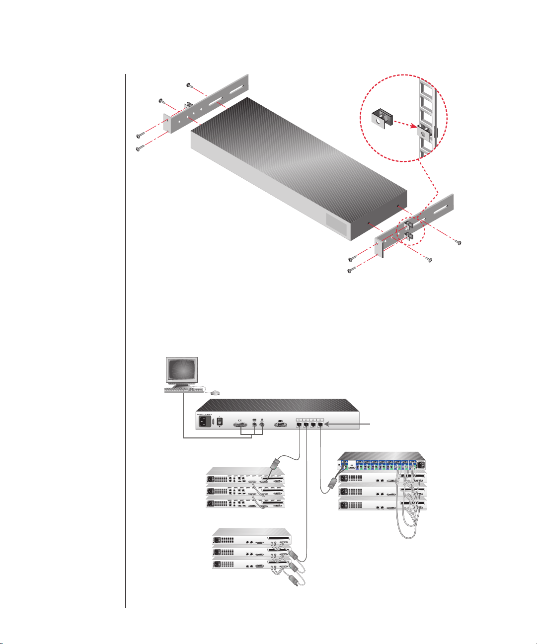
Figure 2.1: LCM Vertical Installation
Horizontal installation in the 1U rack mounting space
1. Line up the holes in the “long side” of the kit’s side brackets with the
screw holes in the switch.
2. With a Phillips screwdriver, fasten the mounting brackets to the switch
using two 8/32”x1/2” pan head screws on each side.
3. Attach the four cage nuts or clip nuts to the rack mounting fl ange of the
rack cabinet so that the nuts are positioned on the inside of the rack.
4. Mount the switch assembly to the rack cabinet by matching the holes in
the “short side” of each bracket to an appropriate set of matching holes on
your rack cabinet. Next, insert the combination hex head screws through
the slots in the bracket and the holes in the mounting rail, then into the
cage nuts or clip nuts.
Page 20
12 LCM Installer and User Guide
Figure 2.2: LCM Horizontal Installation
Cabling the LCM
Figure 2.3 shows one possible configuration for your LCM. Follow the detailed set of
procedures following Figure 2.3 to successfully install your LCM.
Analog Port
Chained C2T
Servers
Up to 16
chained servers
per ARI port
Server
Server
Server
Figure 2.3: Basic LCM Configuration
CAT 5
CCO
KCO
CAT 5
CAT 5
CAT 5
LCM
ARI Ports
CAT 5
IBM NetBAY Switch
Server
Server
Server
KVM
Page 21
Chapter 2: Installation 13
ATT ENT ION : To reduc e the risk of electric shock or damage to your equipment -
- Do not disable the power cord grounding plug. The grounding plug is an important safety feature.
- Plug the power cord into a grounded (earthed) outlet that is easily accessible at all times.
- Disconnect the power from the unit by unplugging the power cord from either the electrical
outlet or the unit.
Statement 4:
DANGER
Electrical current from power, telephone, and communication cables is
hazardous.
To avoid a shock hazard:
•Do not connect or disconnect any cables or perform installation,
maintenance, or reconfiguration of this product during an electrical
storm.
•Connect all power cords to a properly wired and grounded electrical
outlet.
•Connect to properly wired outlets any equipment that will be attached
to this product.
•When possible, use one hand only to connect or disconnect signal
cables.
•Never turn on any equipment when there is evidence of fire, water, or
structural damage.
•Disconnect the attached power cords, telecommunications systems,
networks, and modems before you open the device covers, unless
instructed otherwise in the installation and configuration procedures.
•Connect and disconnect cables as described in the following table
when installing, moving, or opening covers on this product or
attached devices.
To Connect: To Disconnect:
1. Turn everything OFF.
2. First, attach all cables to devices.
3. Attach signal cables to connectors.
4. Attach power cords to outlet.
5. Turn device ON.
1. Turn everything OFF.
2. First, remove power cords from outlet.
3. Remove signal cables from connectors.
4. Remove all cables from devices.
To install the LCM hardware:
1. Plug the supplied power cord into the back of the LCM and then into an
appropriate power source.
2. When the power is turned on, the Power indicator on the back of the unit
will blink for 30 seconds while performing a self-test. Approximately 10
seconds after it stops blinking, press the Enter key to access the main menu.
Page 22

14 LCM Installer and User Guide
To adjust the mouse acceleration:
Before a server can be connected to the LCM, an adjustment to mouse
acceleration must be made. Use the default Microsoft
driver for all attached Microsoft Windows systems attached to the LCM.
®
Windows® PS/2 mouse
For Windows NT
®
(using default drivers):
1. From the desktop, select Start - Settings - Control Panel - Mouse.
2. Click on the Motion tab.
3. Set the pointer speed to Slow. Do this for any Windows NT user account
that will be accessing the Windows NT system through the LCM.
For Microsoft Windows 2000/Windows XP:
1. From the desktop, select Start - Settings - Control Panel - Mouse.
2. Click on the Motion tab.
3. Set the Acceleration setting to None and the speed setting to the default of 50%.
To connect a CCO cable to an IBM C2T server:
1. Locate the CCO cables and CAT 5 cabling for your LCM.
2. Connect the CCO cable to the LCM by attaching one end of the CAT 5
cabling to the RJ45 connector on the CCO cable.
3. Connect the other end of the CAT 5 cable to an ARI port on the back of
your LCM.
4. Attach the C2T connector from the CCO cable into the appropriate port on
the back of your C2T server.
To chain servers together using KCO cables:
1. Locate the KCO cables and CAT 5 cabling for your LCM.
2. Attach one end of the CAT 5 cabling that will run from your KCO cable to
the LCM to the RJ45 connector on the KCO cable.
3. Connect the other end of the CAT 5 cable to an ARI port on the LCM.
4. Attach the appropriately color-coded cable ends to the keyboard, monitor and
mouse ports on the fi rst server you will be connecting to this LCM.
5. Attach one end of the CAT 5 cabling that will connect the fi rst two servers
to the second RJ45 connector on the KCO cable for Server 1.
6. Attach the other end of this cable to the fi rst RJ45 connector on the KCO
cable for Server 2.
7. Repeat steps 4-6 for all servers you chain together.
8. When you reach the end of the chain, attach a terminator to the second
RJ45 connector on the last KCO cable in the chain.
Page 23

Chapter 2: Installation 15
LCM
ARI Port
KCO Cable
CAT 5
cable up to
10 meters
(32.8 feet)
KCO Cable
KCO Cable
Server 1
Server 2
Terminator
Server 3
Figure 2.4: Chaining Servers Together with KCO Cables
To chain servers together using UCO cables:
1. Locate the UCO cables and CAT 5 cabling for your LCM.
2. Attach one end of the CAT 5 cabling that will run from your UCO cable to
the LCM to the RJ45 connector on the UCO cable.
3. Connect the other end of the CAT 5 cable to an ARI port on the LCM.
4. Attach the appropriately color-coded cable ends to the USB and monitor ports
on the fi rst server you will be connecting to this LCM.
5. Attach one end of the CAT 5 cabling that will connect the fi rst two servers
to the second RJ45 connector on the UCO cable for Server 1.
6. Attach the other end of this cable to the fi rst RJ45 connector on the UCO
cable for Server 2.
7. Repeat steps 4-6 for all servers you chain together.
8. When you reach the end of the chain, attach a terminator to the second
RJ45 connector on the last UCO cable in the chain.
Page 24

16 LCM Installer and User Guide
LCM
CAT 5
cable up to
10 meters
(32.8 feet)
Terminator
UCO Cable
Server 1
UCO Cable
Server 2
UCO Cable
Server 3
Figure 2.5: Chaining Servers Together with UCO Cables
To add a legacy KVM switch:
You can add your cascade switches to the LCM system. In a cascaded system,
each ARI port then accommodates up to 24 servers.
LCM
KCO Cable
Terminator
IBM NetBAY Console Switch
1
2 3 4 5 6 7 8
Figure 2.6: LCM Configuration with a Legacy KVM Switch
Server 1
Page 25

Chapter 2: Installation 17
1. Mount the switch into your rack. Locate a length of CAT 5 cabling to
connect your LCM to the CO cable for your switch.
2. Attach one end of the CAT 5 cabling to the RJ45 connector on the CO
cable. Attach a terminator to the second RJ45 connector on the CO.
3. Connect the other end of the CAT 5 cable to a port on the back of your LCM.
4. Attach the keyboard, monitor and mouse connectors of the CO cable to a
user port on your cascade switch.
5. Connect the servers to your switch according to the cascade switch
manufacturer’s recommendations.
6. Repeat steps 2-5 for all cascade switches to be attached to your system.
To operate your LCM with a cascaded multi-user legacy switch:
You can cascade a NetBAY 2x8 console switch under your RCM or LCM.
In a cascaded configuration, the remote and analog workstations can both
access servers attached to the cascaded switch. If both the remote and analog
workstations want to access different servers on the switch at the same time,
you can attach a KVM Conversion Option (KCO) cable to both user ports to
avoid one user blocking the other.
Analog
Workstation
Remote
Workstation
KCO Cable A
KCO Cable B
Second KCO connects
to user port on the front
of the switch
IBM NetBAY
2x8 Switch
Server 1
Server 2
Server 3
KVM
Figure 2.7: Cascaded Multi-user Legacy Switch Configuration
Page 26

18 LCM Installer and User Guide
Preemptive behavior
By default, the console switch operates in preemptive mode. This means
that one user can disconnect another user from a server connection without
warning. For example, if the analog user is accessing server 1 via KCO cable
A and the remote user switches to the same server via KCO cable B, the
analog user will be preempted and the remote user will take command of the
connection. The analog user’s screen will go blank and they will receive no
disconnect warning.
If you will have users performing sensitive tasks who should not be
preempted, you can connect only one CO cable to the switch. This will ensure
that no user can preempt another without administrative privileges at the
remote console.
To turn on your LCM system:
The components in the LCM system may be turned on in any order. However,
since the CO cables are powered by the servers, turn on the servers first and
then turn on all attached systems for the most efficient startup.
To use more than one regional language keyboard in a system:
You may need to configure your remote console to synchronize with a target
server if the keyboard of that server is set up for a different language than your
remote console. For instance, if you are using a French (AZERTY) keyboard on
the remote console and you connect to a target server that is using an English
(QWERTY) keyboard, you will need to create a second keyboard on the remote
workstation (English keyboard).
To verify a target server’s keyboard language:
1. Launch the Virtual Console software at the remote workstation.
2. Click the Devices tab and then the target server.
3. Click the Connect Video task button.
4. On the target server for Microsoft Windows 2000 select Start - Settings -
Control Panel - Regional Options. For other operating systems, see the
user guide that comes with your system.
5. Verify the language.
To synchronize languages with the target server:
1. At the remote station for Microsoft Windows 2000 select Start - Settings
- Control Panel - Regional Options. Select the language for the target server.
For other operating systems, see the user guide that comes with your system.
2. The languages should now be synchronized.
Page 27

3
Basic Operations
Contents
Controlling Your System . . . . . . . . . . . . . . . . . . . . . . . . .21
Viewing and Selecting Ports and Servers . . . . . . . . . . . .21
Configuring OSCAR . . . . . . . . . . . . . . . . . . . . . . . . . . . .24
Resetting Your Keyboard and Mouse . . . . . . . . . . . . . . 32
Displaying Version Information . . . . . . . . . . . . . . . . . . .33
Scanning Your System . . . . . . . . . . . . . . . . . . . . . . . . . . 34
Broadcasting to Servers . . . . . . . . . . . . . . . . . . . . . . . . . . 36
Page 28

Page 29
Chapter 3: Basic Operations 21
Chapter 3: Basic Operations
Controlling Your System
The LCM includes an analog port on the back of the unit that allows you to
connect a monitor and a PS/2 keyboard and mouse for direct analog access. The
LCM uses the On-Screen Configuration and Activity Reporting interface (OSCAR
for IBM which has intuitive menus to configure your system and select computers.
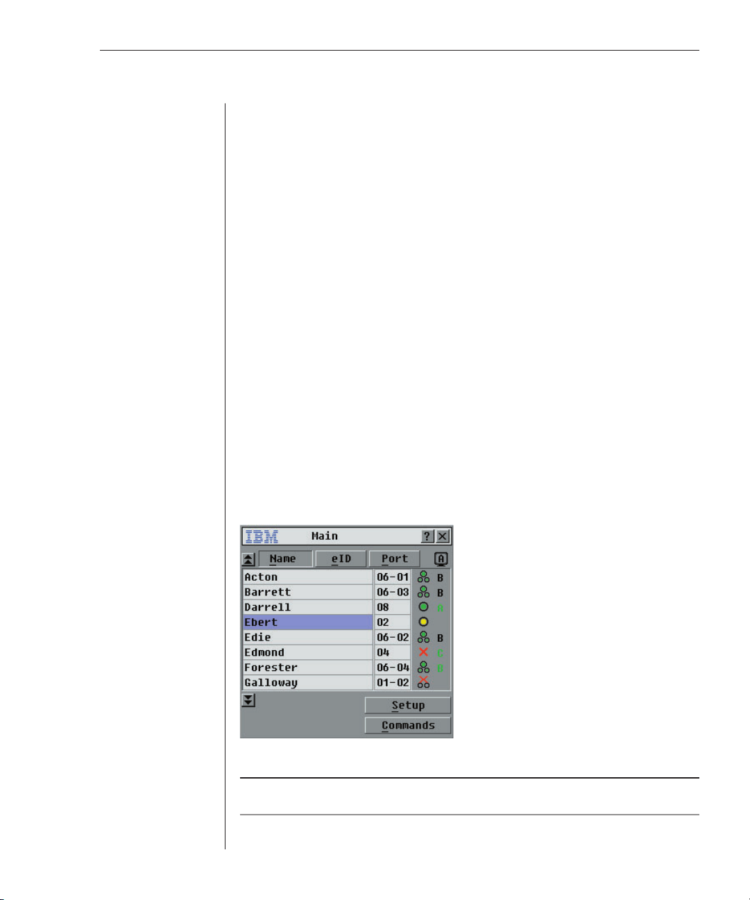
Viewing and Selecting Ports and Servers
Use the OSCAR Main dialog box to view, configure and control servers in the
LCM system. You can view your servers by name, port or by the unique electronic
ID number (eID) embedded in each CO cable. You will see an OSCAR-generated
Name list by default when you first launch OSCAR.
The port column indicates the ARI port to which a server is connected. If you
connect a legacy switch to the LCM, the port numbering displays the ARI port
first, then the port to which the server is connected. For example, in Figure 3.1,
servers 06-03 and 01-02 are connected to legacy switches.
To access the Main dialog box:
Press Print Screen to launch OSCAR. The Main dialog box appears.
-orIf a password has been assigned, the Password dialog box appears. Type in
your password and click OK. The Main dialog box appears. For more
information, see Setting console security in this chapter.
®
)
Figure 3.1: Example of Configured Main Dialog Box
NOTE: You c a n also press the Control key twice within one second to launch OSCAR. You can
use this key sequence in any place you see Print Screen throughout this Installer and User Guide.
Page 30

22 LCM Installer and User Guide
Viewing the status of your LCM system
The status of servers in your system is indicated in the far right column of the
Main dialog box. The following table describes the status symbols.
OSCAR Status Symbols
Symbol Description
CO cable is online.
CO cable is offl ine or is not operating properly.
Connected switch is online.
Connected switch is offl ine or is not operating properly.
CO cable is being upgraded.
Selecting servers
Use the Main dialog box to select servers. When you select a server, the LCM
reconfigures the keyboard and mouse to the proper settings for that server.
To select servers:
Double-click the server name, eID or port number.
-or-
If the display order of your server list is by port (Port button is depressed), type
the port number and press Enter.
-or-
If the display order of your server list is by name or eID number (Name or eID
button is depressed), type the first few characters of the name of the server or
the eID number to establish it as unique and press Enter.
To select the previous server:
Press Print Screen and then Backspace. This key combination toggles you
between the previous and current connections.
To disengage the user from a server:
Press Print Screen and then Alt+Ø. This leaves the user in a free state, with no
server selected. The status flag on your desktop displays Free.
Soft switching
Soft switching is the ability to switch servers using a hotkey sequence. You
can soft switch to a ser ver by pressing Print Screen and then typing the first
few characters of its name or number. If you have a delay time set and you
press the key sequences before that time has elapsed, OSCAR will not display.
Page 31

Chapter 3: Basic Operations 23
To confi gure servers for soft switching:
1. Press Print Screen to launch OSCAR. The Main dialog box appears.
2. Click Setup - Menu. The Menu dialog box appears.
3. For delay time, type the number of seconds of delay desired before the
Main dialog box is displayed after Print Screen is pressed.
4. Click OK.
To soft switch to a server:
1. To select a server, press Print Screen. If the display order of your server list
is by port (Port button is depressed), type the port number and press Enter.
-orIf the display order of your server list is by name or eID number (Name or
eID button is depressed), type the fi rst few characters of the name of the
server or the eID number to establish it as unique and press Enter.
2. To switch back to the previous server, press Print Screen then Backspace.
OSCAR navigation basics
The following table describes how to use the keyboard and mouse to
navigate OSCAR.
This Keystroke Does This
Print Screen Opens OSCAR. Press Print Screen twice to send the Print
Screen keystroke to the currently selected device.
F1 Opens the Help screen for the current dialog box.
Escape Closes the current dialog box without saving changes and
returns to the previous one. In the Main dialog box, it closes
OSCAR and returns to the selected server. In a message box,
it closes the pop-up box and returns to the current dialog box.
Alt Opens dialog boxes, selects options and executes actions when
used in combination with underlined or other designated letters.
Alt+X Closes current dialog box and returns to the previous one.
Alt+O Selects the OK button, then returns to the previous dialog box.
Enter Completes the switch operation in the Main dialog box and
exits OSCAR.
Single-click, Enter In a text box, it selects the text for editing and enables the Left
and Right Arrow keys to move the cursor. Press Enter again
to quit the edit mode.
Print Screen, Alt+Ø Immediately disengages user from a server; no server is
selected. Status fl ag displays Free. (This only applies to the Ø
on the keyboard and not the keypad.)
Page 32

24 LCM Installer and User Guide
OSCAR Navigation Basics (continued)
This Keystroke Does This
Print Screen, Backspace Toggles back to previous selection if no other keystrokes have
Print Screen, Pause Immediately turns on screen saver mode and prevents access
Up/Down Arrows Moves the cursor from line to line in lists.
Right/Left Arrows Moves the cursor between columns. When editing a text box,
Page Up/Page Down Pages up and down through Name and Port lists.
Home/End Moves the cursor to the top or bottom of a list.
Backspace Erases characters in a text box.
Delete Deletes current selection in the scan list or characters in a text box.
Shift-Del Deletes from the current selection to the end of the list when
Numbers Type from the keyboard or keypad.
Caps Lock Disabled. Use the Shift key to change case.
been typed.
to that particular console, if it is password protected.
these keys move the cursor within the column.
editing a scan list.
Configuring OSCAR
You can configure your LCM system from the Setup menu within OSCAR.
Select the Names button when initially setting up your LCM system to identify
servers by unique names. Select the other setup features to manage routine
tasks for your servers from the OSCAR menu.
To access the Setup menu:
1. Press Print Screen to launch OSCAR. The Main dialog box appears.
2. Click Setup. The Setup dialog box appears.
Figure 3.2: Setup Dialog Box
Page 33

Chapter 3: Basic Operations 25
Setup Features to Manage Routine Tasks for Your Servers
Feature Purpose
Menu Change the server listing between numerically by port or eID number and
alphabetically by name.
Change the delay time before OSCAR displays after pressing Print Screen.
Flag Change display, timing, color or location of the status fl ag.
Broadcast
Scan Set up a custom scan pattern for up to 16 servers.
Security Set passwords to restrict server access.
Enable the screen saver.
Devices Identify the appropriate number of ports on an attached cascade switch.
Names Identify servers by unique names.
Set up to simultaneously control multiple servers through keyboard and mouse actions.
Assigning server names
Use the Names dialog box to identify individual servers by name rather than by
port number. The Names list is always sorted by port order. Names are stored in
the CO cable, so even if you move the cable/server to another ARI port, the name
and configuration will be recognized by the LCM.
NOTE: If a server is turned off, its respective CO cable will not appear in the Names list.
To access the Names dialog box:
1. Press Print Screen. The Main dialog box will appear.
2. Click Setup - Names. The Names dialog box appears.
Figure 3.3: Names Dialog Box
NOTE: If the server list changes, the mouse cursor will turn into an hourglass as the list is
automatically updated. No mouse or keyboard input will be accepted until the list update is complete.
Page 34
26 LCM Installer and User Guide
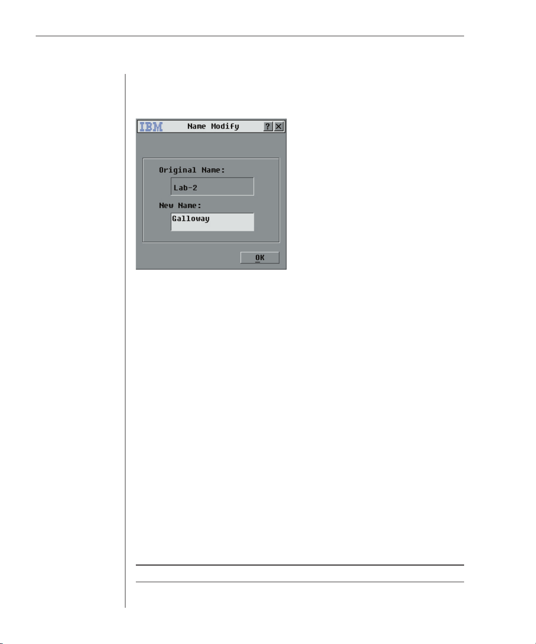
To assign names to servers:
1. In the Names dialog box, select a name or port number and click Modify.
The Name Modify dialog box appears.
Figure 3.4: Name Modify Dialog Box
2. Type a name in the New Name box. Names of servers may be up to 15
characters long. Legal characters include: A-Z, a-z, Ø-9, space and hyphen,
in any combination.
3. Click OK to transfer the new name to the Names dialog box. Your selection
is not saved until you click OK in the Names dialog box.
4. Repeat steps 1-3 for each server in the system.
5. Click OK in the Names dialog box to save your changes.
-orClick X or press Escape to exit the dialog box without saving changes.
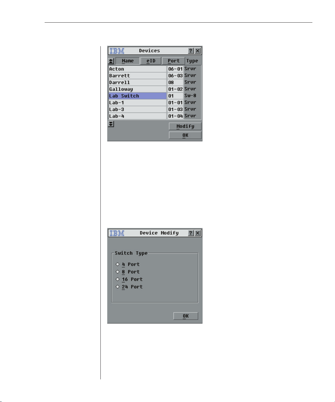
Assigning device types
While the LCM automatically discovers cascade switches attached to your
unit, you will need to specify the number of ports on the cascade switch
through the Devices dialog box. You will see an Sw-8 designation appear in the
Type category. When you select that switch from the list, the Modify button
appears, allowing you to assign the appropriate number of ports to it.
To access the Devices dialog box:
1. Press Print Screen. The Main dialog box will appear.
2. Click Setup - Devices. The Devices dialog box appears.
NOTE: The Modify button will only be available if a confi gurable switch is selected.
Page 35
Chapter 3: Basic Operations 27
Figure 3.5: Devices Dialog Box
When the LCM discovers a cascade switch, you will notice the port numbering
change to accommodate each server under that switch. For example, if the
switch is connected to port 2, the switch port would be listed as 02 and each
server under it would be numbered sequentially 02-01, 02-02 and so on.
To assign a device type:
1. In the Devices dialog box, select the desired port number.
2. Click Modify. The Device Modify dialog box appears.
Figure 3.6: Device Modify Dialog Box
3. Choose the number of ports supported by your switch and click OK.
4. Repeat steps 1–3 for each port to which you want to assign a device type.
5. Click OK in the Devices dialog box to save settings.
Page 36

28 LCM Installer and User Guide
NOTE: Changes made in the Device Modify dialog box are not saved until you click OK in the
Devices dialog box.
Changing the display behavior
Use the Menu dialog box to change the display order of servers and set a
Screen Delay Time for OSCAR.
To access the Menu dialog box:
1. Press Print Screen to launch OSCAR. The Main dialog box appears.
2. Click Setup - Menu in the Main dialog box. The Menu dialog box appears.
Figure 3.7: Menu Dialog Box
To choose the display order of servers in the Main dialog box:
1. Select Name to display servers alphabetically by name.
-orSelect eID to display servers numerically by eID number.
-orSelect Port to display servers numerically by port number.
2. Click OK.
To set a Screen Delay Time for OSCAR:
1. T y pe i n t he number of seconds (Ø- 9) you want to delay OSCAR display
after you press Print Screen. Entering Ø will instantly launch OSCAR
with no delay.
2. Click OK.
Setting a Screen Delay Time allows you to complete a soft switch without
OSCAR displaying. To perform a soft switch, see Soft switching in this chapter.
Page 37

Chapter 3: Basic Operations 29
Controlling the status flag
The status flag displays on your desktop and shows the name or eID number
of the selected server or the status of the selected port. Use the Flag dialog box
to configure the flag to display by server name or eID number, or to change the
flag color, opacity, display time and location on the desktop.
OSCAR Status Flags
Flag Description
Flag type by name
Flag type by eID number
Flag indicating that the user has been disconnected from all systems
Flag indicating that Broadcast mode is enabled
To access the Flag dialog box:
1. Press Print Screen. The Main dialog box will appear.
2. Click Setup - Flag. The Flag dialog box appears.
Figure 3.8: Flag Dialog Box
To determine how the status fl ag is displayed:
1. Select Name or eID to determine what information will be displayed.
2. Select Displayed to show the fl ag all the time or select Timed to display
the fl ag for only fi ve seconds after switching.
3. Select a fl ag color in Display Color.
4. In Display mode, select Opaque for a solid color fl ag or select Transparent
to see the desktop through the fl ag.
5. To position the status fl ag on the desktop:
a. Click Set Position to gain access to the Position Flag screen.
Page 38

30 LCM Installer and User Guide
b. Left-click on the title bar and drag to the desired location.
c. Right-click to return to the Flag dialog box.
Figure 3.9: Set Position Flag
NOTE: Changes made to the fl ag position are not saved until you click OK in the Flag dialog box.
6. Click OK to save settings.
-orClick X to exit without saving changes.
Setting console security
OSCAR enables you to set security on your analog port console. You can
establish a screen saver mode that engages after your console remains unused
for a specified delay time. Once engaged, your console will remain locked until
you press any key or move the mouse. You will then need to type in your
password to continue.
Use the Security dialog box to lock your console with password protection, set
or change your password and enable the screen saver.
NOTE: If a password has been previously set, you will have to enter the password before being
able to access the Security dialog box.
To access the Security dialog box:
1. Press Print Screen. The Main dialog box will appear.
2. Click Setup - Security. The Security dialog box appears.
Figure 3.10: Security Dialog Box
Page 39

Chapter 3: Basic Operations 31
To set or change the password:
1. Single-click and press Enter or double-click in the New text box.
2. Type the new password in the New text box and press Enter.
Passwords may be up to 12 characters long and are case sensitive. Legal
characters are: A-Z, a-z, Ø-9, space and hyphen. The password must
contain both alpha and numeric characters.
3. In the Repeat box, type the password again and press Enter.
4. Click OK to change your password, and then close the dialog box.
To password protect your console:
1. Set your password as described in the previous procedure.
2. Select Enable Screen Saver.
3. Type the number of minutes for Inactivity Time (from 1 to 99) to delay
activation of password protection and the screen saver feature.
4. For Mode, select Energy if your monitor is E
otherwise select Screen.
ATT ENT ION : Monitor damage can result from the use of Energy mode with monitors not
compliant with ENERGYSTAR .
NERGY STAR compliant;
5. (Optional) Click Test to activate the screen saver test which lasts 10
seconds then returns you to the Security dialog box.
6. Click OK.
To log in to your console:
1. Press any key or move the mouse.
2. The Password dialog box appears. Type your password and then click OK.
3. The Main dialog box appears if the password was entered properly.
To remove password protection from your console:
1. From the Main dialog box, click Setup - Security; the Password dialog box
appears. Type your password, then click OK.
2. In the Security dialog box, single-click and press Enter or double-click in
the New box. Leave the box blank. Press Enter.
3. Single-click and press Enter or double-click in the Repeat box. Leave the
box blank. Press Enter.
4. Click OK to eliminate your password.
To enable the screen saver mode with no password protection:
1. If your console does not require a password to gain access to the Security
dialog box, go to step 2.
Page 40

32 LCM Installer and User Guide
-orIf your console is password protected, see the previous procedure, then go
to step 2.
2. Select Enable Screen Saver.
3. Type the number of minutes for delay time (from 1–99) that you want to
delay activation of the screen saver.
4. Choose Energy if your monitor is E
select Screen.
ATT ENT ION : Monitor damage can result from the use of Energy mode with monitors not
compliant with ENERGY STAR .
5. (Optional) Click Test to activate the screen saver test which lasts 10
seconds then returns you to the Security dialog box.
6. Click OK.
NOTE: Activation of the screen saver mode disconnects the user from a server; no server is
selected. The status fl ag displays Free.
To exit the screen saver mode:
Press any key or move your mouse. The Main dialog box appears.
NERGY STAR compliant; otherwise
To turn off the screen saver:
1. In the Security dialog box, clear Enable Screen Saver.
2. Click OK.
To immediately turn on the screen saver:
Press Print Screen, then press Pause.
Resetting Your Keyboard and Mouse
If your keyboard or mouse stops responding, you may be able to re-establish
operation of these peripherals by issuing a reset command. The reset
command sends a key sequence to the server which causes the mouse and
keyboard settings to be sent to the LCM. With communication re-established
between the server and the LCM, functionality is restored to the user.
To reset the mouse and keyboard values:
1. Press Print Screen. The Main dialog box will appear.
2. Click Commands - Reset PS/2. A message box displays indicating that the
mouse and keyboard have been reset.
3. Click X to close the message box.
Page 41
Chapter 3: Basic Operations 33
Displaying Version Information
OSCAR enables you to display the CO cable firmware versions. For optimum
performance, keep your firmware current. For more information, see Appendix A.
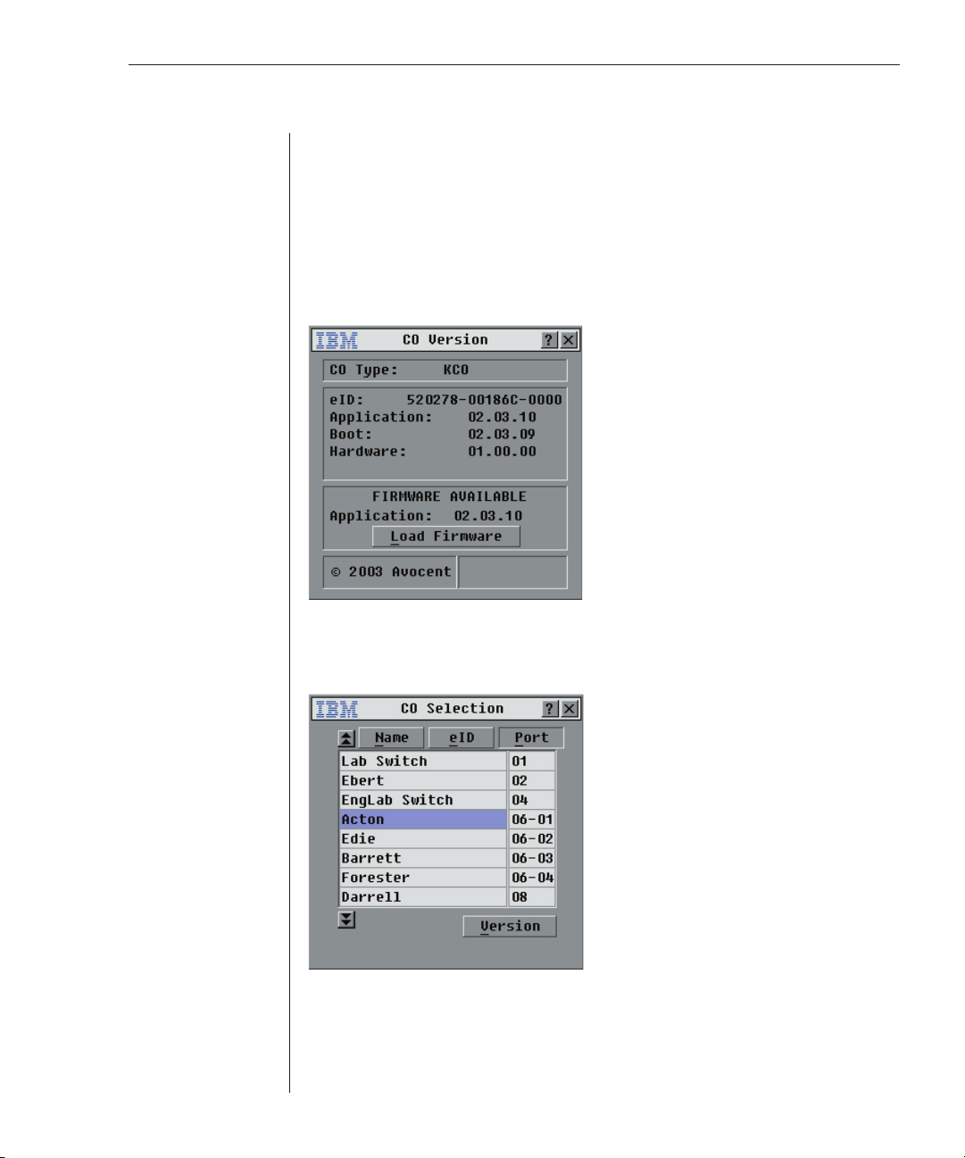
To display version information:
1. Press Print Screen. The Main dialog box will appear.
2. Click Commands - Display Versions. The Version dialog box appears. The
top half of the box lists the subsystem versions in the LCM.
Figure 3.11: CO Version Dialog Box
3. Click CO to view individual KCO, UCO or CCO version information. The
CO Selection dialog box appears.
Figure 3.12: CO Selection Dialog Box
4. Select a KCO, UCO or CCO cable and click the Version button. The CO
Version dialog box appears. For more information on loading fi rmware,
see Appendix A.
Page 42

34 LCM Installer and User Guide
Figure 3.13: CO Version Dialog Box
5. Click X to close the Version dialog box.
Scanning Your System
In scan mode, the LCM automatically scans from port to port (server to
server). You can scan up to 16 servers, specifying which servers you want to
scan and the number of seconds that each server will display. The scanning
order is determined by placement of the server in the list. The list is always
shown in scanning order. You can, however, choose to display the server’s
name or eID number by pressing the appropriate button.
To add servers to the Scan list:
1. Press Print Screen. The Main dialog box will appear.
2. Click Setup - Scan. The Scan dialog box appears.
Figure 3.14: Scan Dialog Box
Page 43

Chapter 3: Basic Operations 35
3. Select the order within the list where you want to add a server. If no
servers have been added to the scan list, your cursor will appear in a
blank line at the top of the dialog box.
-orTo add a server to the end of the list, place your cursor in the last server
entry and press the Down Arrow key.
-orTo add a server in the the midst of an existing list, place your cursor in the
line below where you want to insert a new server and press Insert.
4. Type the fi rst few characters of a server name or port number to scan. The
fi rst matching server will appear in the line.
-orTo move through the server list, press the following keyboard commands
in the Name, Port or Sec column to move through the list of servers
available to scan.
a. Press Alt+Down Arrow to move the cursor down through the list of servers.
b. Press Alt+Up Arrow to move the cursor up through the list of servers.
c. Press Alt+Home to move the cursor to the fi rst server in the list.
d. Press Alt+End to move the cursor to the last server in the list.
5. In the Sec column, type the number of seconds (from 3 to 255) of desired
delay time before the scan moves to the next server in the sequence.
6. Move the cursor to the next line or press the Down Arrow and repeat steps
2-5 for each of the remaining servers to be included in the scan pattern.
7. Click OK.
To remove a server from the scan list:
1. In the Scan dialog box, click the server to be removed.
2. Press Delete.
-orPress Shift+Delete to remove the selected server and all entries below it.
3. Click OK.
To start the scan mode:
1. Press Print Screen. The Main dialog box will appear.
2. Click Commands. The Commands dialog box appears.
Page 44

36 LCM Installer and User Guide
Figure 3.15: Commands Dialog Box
3. Select Scan Enable in the Commands dialog box.
To cancel scan mode:
1. Select a server if OSCAR is open.
-orMove the mouse or press any key on the keyboard if OSCAR
is not open. Scanning will stop at the currently selected server.
-orPress Print Screen. The Main dialog box will appear.
2. Click Commands. The Commands dialog box appears.
3. Clear Scan Enable.
Broadcasting to Servers
The analog user can simultaneously control more than one server in a system,
to ensure that all selected servers receive identical input. You can choose to
broadcast keystrokes and/or mouse movements independently.
To access the Broadcast dialog box:
1. Press Print Screen. The Main dialog box will appear.
2. Click Setup - Broadcast. The Broadcast dialog box appears.
Page 45

Chapter 3: Basic Operations 37
Figure 3.16: Broadcast Dialog Box
NOTE: Broadcasting Keystrokes - The keyboard state must be identical for all ser vers
receiving a broadcast to interpret keystrokes identically. Specifi cally, the Caps Lock and Num
Lock modes must be the same on all keyboards. While the LCM attempts to send keystrokes to
the selected servers simultaneously, some servers may inhibit and thereby delay the transmission.
NOTE: Broadcasting Mouse Movements - For the mouse to work accurately, all systems
must have identical mouse drivers, desktops (such as identically placed icons) and video
resolutions. In addition, the mouse must be in exactly the same place on all screens. Because
these conditions are extremely diffi cult to achieve, broadcasting mouse movements to multiple
systems may have unpredictable results.
To broadcast to selected servers:
1. From the Broadcast dialog box, select the mouse and keyboard
checkboxes for the servers that are to receive the broadcast commands.
-orPress the Up or Down Arrow keys to move the cursor to the target server.
Then press Alt+K to select the keyboard checkbox and/or Alt+M to select
the mouse checkbox. Repeat for additional servers.
2. Click OK to save the settings and return to the Setup dialog box. Click X or
press Escape to return to the Main dialog box.
3. Click Commands. The Command dialog box appears.
4. Click the Broadcast Enable checkbox to activate broadcasting.
5. From the user station, type the information and/or perform the mouse
movements you want to broadcast.
To turn broadcasting off:
From the Command dialog box, clear the Broadcast Enable checkbox.
Page 46

38 LCM Installer and User Guide
Page 47

Appendices
Contents
Appendix A: FLASH Upgrades . . . . . . . . . . . . . . . . . . . . 41
Appendix B: Technical Specifications . . . . . . . . . . . . . .45
Appendix C: Hardware Maintenance Information . . . . 46
Appendix D: Notices . . . . . . . . . . . . . . . . . . . . . . . . . . . .47
Page 48

Page 49

Appendices 41
Appendices
Appendix A: FLASH Upgrades
Upgrading the LCM
The LCM FLASH upgrade feature allows you to upgrade your unit with the
latest firmware available. To perform this upgrade, you will need to download
the latest FLASH firmware from IBM.
To upgrade your fi rmware, you need the following items:
• Computer running a Microsoft Windows operating system
• Available serial port (COM port) on the server
• Standard serial cable (DB-male) that connects the switch and the server
• Firmware upgrade
To upgrade fi rmware:
1. Connect the standard serial cable to a COM port on the server and to the
serial connector on the back panel of the LCM. Note which COM port you
have chosen, then turn on the switch.
2. Go to http://www.ibm.com/pc/support to access the fi rmware upgrade fi le.
Once the download is complete, navigate to the drive where you have
saved the fi rmware upgrade and unzip the fi le.
3. Double-click to run WUpDate.exe.
4. In the dialog box that displays, select the desired language and COM port.
5. Click Load.
ATT ENT ION : While downloading, do not use your computer for anything else or switch
windows. The download requires constant control of your computer, and switching to
another window may cause the download to time-out. If a time- out occurs, run the WUpDate
program again.
6. Once the fi rmware is upgraded, the following message displays:
Download complete. Click Done to exit the dialog box.
7. The switch automatically restarts after the upgrade is completed.
Possible error conditions
If the download does not execute correctly, verify the following:
• Verify that the COM port is correct.
• Verify that no other program is currently using that COM port.
• Verify that no other copies of the WUpdate utility are currently running.
• Verify that a straight-through (1-to-1) serial cable is used, not a null
modem serial cable.
• Verify in Advanced Port Settings for the selected COM port that it is using
FIFO buffers and the receive buffer is set to high.
Page 50
42 LCM Installer and User Guide
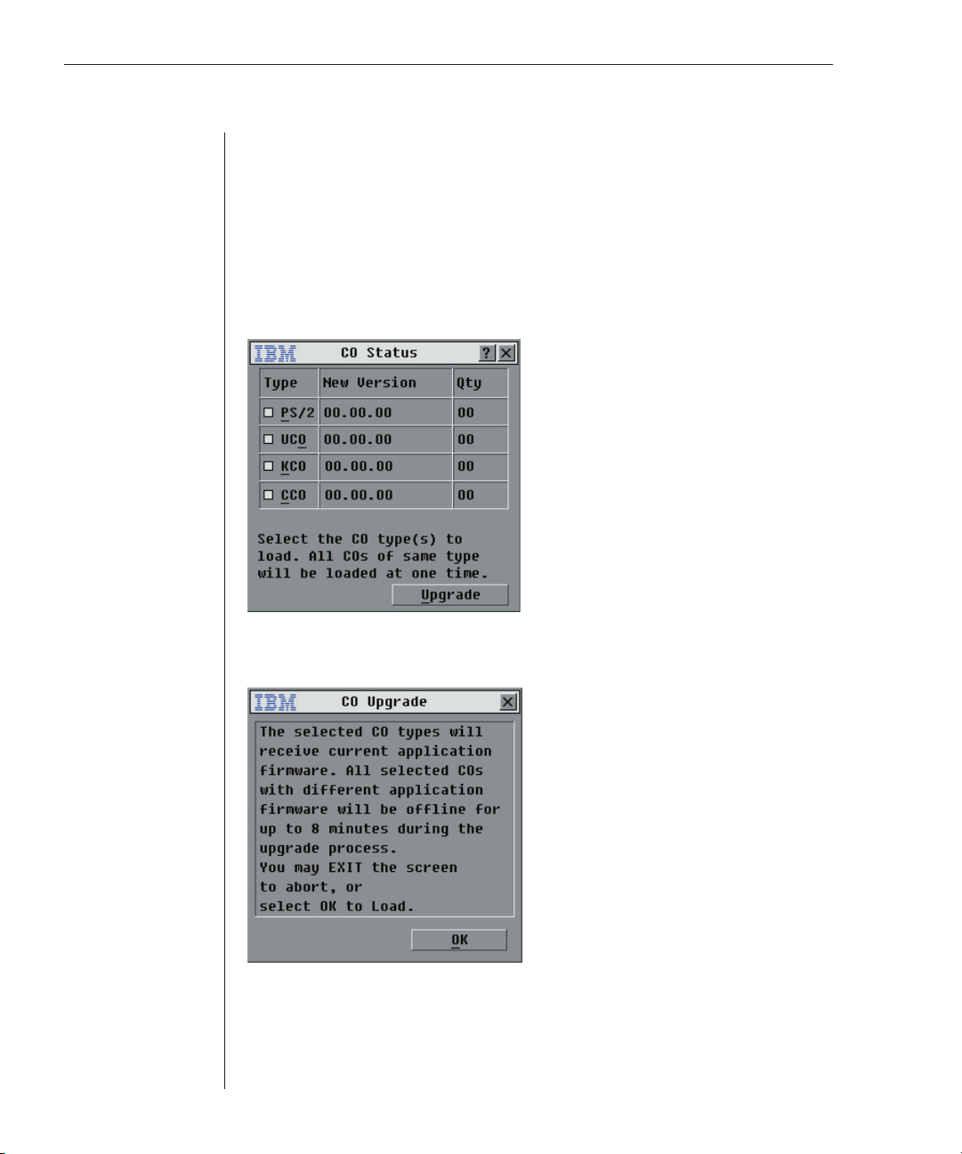
Upgrading the CO cable firmware
The CO cables can be upgraded individually or simultaneously. When an
upgrade is initiated, you will see a progress bar. As long as an upgrade is in
progress, you cannot initiate another.
To simultaneously upgrade multiple CO cables:
1. Press Print Screen. The Main dialog box will appear.
2. Click Commands - CO Status. The CO Status dialog box appears.
Figure A.1: CO Status Dialog Box
3. Click one or more types of cables to upgrade. Click Upgrade.
Figure A.2: CO Upgrade Dialog Box
4. The CO Upgrade dialog box appears. Click OK to initiate the upgrade and
return to the CO Status dialog box.
Page 51

Appendices 43
To upgrade CO cable fi rmware individually:
1. Press Print Screen. The Main dialog box will appear.
2. Click Commands - Display Versions. The Version dialog box appears.
Figure A.3: Version Dialog Box
3. Click CO to view individual cable version information.
Figure A.4: CO Selection Dialog Box
4. Select a CO cable to upgrade and click the Version button. The CO Version
dialog box appears.
Page 52

44 LCM Installer and User Guide
Figure A.5: CO Version Dialog Box
5. Click the Load Firmware button. The CO Load dialog box appears.
Figure A.6: CO Load Dialog Box
6. Click OK to initiate the upgrade and return to the CO Status dialog box.
Page 53

Appendices 45
Appendix B: Technical Specifications
LCM Product Specifi cations
Server Ports
Number 4
Types KCO, CCO and UCO intelligent cables
Connectors RJ45
Sync Types Separate horizontal and vertical
Plug and Play DDC2B
Video Resolution Analog Port Maximum 1600 x 1280 @ 75 Hz
Confi guration Port
Number 1
Type Serial RS232
Connector DB9 Female
Analog Port
Number 1
Type PS/2 and VGA
Connectors PS/2 MiniDIN and 15-pin D
Dimensions
Dimensions (HxWxD) 4.38 x 43.18 x 13.97 cm 1U form factor
Weight 1.6 kg (3.6 lb) without cables
Heat Dissipation 17 BTU/Hr
Power Consumption 5 W
AC -input power 10 W maximum
AC -input voltage rating 100 to 240 VAC Autosensing
AC -input current rating .1A
AC-input cable 18 AWG three-wire cable, with a three-lead IEC-320
AC -frequency 50/60 Hz
Temperature 10º to 50º Celsius (50º to 122º Fahrenheit) operating
Humidity 20 to 80% noncondensing operating
Agency Approvals
EN55022 Class A, EN55024, EN61000-3-3, FCC15 Class A, VCCI Class A, IEC950,
(1.72 x 17. 00 x 5.75 in)
receptacle on the power supply end and a country or
region dependent plug on the power resource end
-20º to 60º Celsius (-4º to 140º Fahrenheit) nonoperating
5 to 95% noncondensing nonoperating
EN60950, UL 60950 third edition, CSA C22.2 No. 60950
Page 54

46 LCM Installer and User Guide
Appendix C: Hardware Maintenance Information
This appendix contains information about IBM Field Replaceable Unit (FRU)
availability for the LCM. Troubleshooting and servicing of complex problems
should be performed only by trained service personnel.
Field Replaceable Unit part numbers
IBM FRU part numbers are subject to change without notice. The following
table contains a listing of the FRU part numbers available at the time this
document was published.
LCM
KCO
Horizontal 1U
Mounting Brackets
Figure C.1: FRU Parts
Vertical
Mounting Brackets
FRU Part Numbers
FRU Part # Description
P/N: 32P1644 NetBAY 4 Port Local Console Manager (LCM) FRU
P/N: 32P1646 C2T Conversion Option (CCO) FRU
P/N: 32P1645 KVM Conversion Option (KCO) (short, 250mm) FRU
P/N: 32P1654 KVM Conversion Option (KCO) (long, 1.5M) FRU
P/N: 73P5835 USB Conversion Option (UCO) FRU
P/N: 32P1711 Miscellaneous FRU Parts Kit
P/N: 32P1713 Terminator FRU Kit
UCOCCO
Page 55

Appendices 47
Appendix D: Notices
This publication was developed for products and services offered in the U.S.A.
IBM may not offer the products, services, or features discussed in this document in other
countries. Consult your local IBM representative for information on the products and
services currently available in your area. Any reference to an IBM product, program,
or service is not intended to state or imply that only that IBM product, program, or
service may be used. Any functionally equivalent product, program, or service that does
not infringe any IBM intellectual property right may be used instead. However, it is
the user’s responsibility to evaluate and verify the operation of any non-IBM product,
program, or service.
IBM may have patents or pending patent applications covering subject matter described
in this document. The furnishing of this document does not give you any license to these
patents. You can send license inquiries, in writing, to:
IBM Director of Licensing
IBM Corporation
North Castle Drive
Armonk, NY 10504-1785
U.S.A.
INTERNATIONAL BUSINESS MACHINES CORPORATION PROVIDES THIS
PUBLICATION “AS IS” WITHOUT WARRANTY OF ANY KIND, EITHER EXPRESS OR
IMPLIED, INCLUDING, BUT NOT LIMITED TO, THE IMPLIED WARRANTIES OF NONINFRINGEMENT, MERCHANTABILITY OR FITNESS FOR A PARTICULAR PURPOSE.
Some jurisdictions do not allow disclaimer of express or implied warranties in certain
transactions, therefore, this statement may not apply to you.
This information could include technical inaccuracies or typog raphical errors.
Changes are periodically made to the information herein; these changes will be
incorporated in new editions of the publication. IBM may make improvements and/or
changes in the product (s) and/or the program(s) described in this publication at any
time without notice.
Any references in this publication to non-IBM Web sites are provided for convenience
only and do not in any manner serve as an endorsement of those Web sites. The
materials at those Web sites are not part of the materials for this IBM product, and use of
those Web sites is at your own risk.
IBM may use or distribute any of the information you supply in any way it believes
appropriate without incurring any obligation to you.
Edition notice
© COPYRIGHT INTERNATIONAL BUSINESS MACHINES CORPORATION, 2003. All
rights reserved.
Note to U.S. Government Users — Documentation related to restricted rights — Use,
duplication or disclosure is subject to restrictions set forth in GSA ADP Schedule
Contract with IBM Corp.
Page 56

48 LCM Installer and User Guide
Trademarks
IBM and NetBAY are trademarks of International Business Machines Corporation in the
United States, other countries, or both.
Microsoft, Windows and Windows NT are trademarks of Microsoft Corporation in the
United States, other countries, or both.
Linux is a registered trademark of Linus Torvalds.
Other company, product, or service names may be the trademarks or service marks
of others.
Important notes
Processor speeds indicate the internal clock speed of the microprocessor; other factors
also affect application performance.
CD-ROM drive speeds list the variable read rate. Actual speeds vary and are often less
than the maximum possible.
When referring to processor storage, real and virtual storage, or channel volume, KB
stands for approximately 1000 bytes, MB stands for approximately 1 000 000 bytes, and
GB stands for approximately 1 000 000 000 bytes.
When referring to hard disk drive capacity or communications volume, MB stands for
1 000 000 bytes, and GB stands for 1 000 000 000 bytes. Total user-accessible capacity
may vary depending on operating environments.
Maximum internal hard disk drive capacities assume the replacement of any standard
hard disk drives and population of all hard disk drive bays with the largest currently
supported drives available from IBM.
Maximum memory may require replacement of the standard memory with an optional
memory module.
IBM makes no representation or warranties regarding non-IBM products and services
that are ServerProven®, including but not limited to the implied warranties of
merchantability and fitness for a particular purpose. These products are offered and
warranted solely by third parties.
IBM makes no representations or warranties with respect to non-IBM products. Support
(if any) for the non-IBM products is provided by the third party, not IBM.
Some software may differ from its retail version (if available), and may not include user
manuals or all program functionality.
Page 57

Appendices 49
Electronic emission notices
Federal Communications Commission (FCC) statement
NOTE: This equipment has been tested and found to comply with the limits for a
Class A digital device, pursuant to Part 15 of the FCC Rules. These limits are designed
to provide reasonable protection against harmful interference when the equipment is
operated in a commercial environment. This equipment generates, uses, and can radiate
radio frequency energy and, if not installed and used in accordance with the instruction
manual, may cause harmful interference to radio communications. Operation of this
equipment in a residential area is likely to cause harmful interference, in which case the
user will be required to correct the interference at his own expense.
Properly shielded and grounded cables and connectors must be used in order to meet
FCC emission limits. Properly shielded and grounded cables and connectors must be
used in order to meet FCC emission limits. IBM is not responsible for any radio or
television interference caused by using other than recommended cables and connectors
or by unauthorized changes or modifications to this equipment. Unauthorized changes
or modifications could void the user’s authority to operate the equipment.
This device complies with Part 15 of the FCC Rules. Operation is subject to the
following two conditions: (1) this device may not cause harmful interference, and (2)
this device must accept any interference received, includi ng interference that may
cause undesired operation.
Industry Canada Class A emission compliance statement
This Class A digital apparatus complies with Canadian ICES-003.
Avis de conformité à la réglementation d’Industrie Canada
Cet appareil numérique de la classe A est conforme à la norme NMB-003 du Canada.
Australia and New Zealand Class A statement
ATTENTION: This is a Class A product. In a domestic environment this product may
cause radio interference in which case the user may be required to take adequate
measures.
United Kingdom telecommunications safety requirement
Notice to customers
This apparatus is approved under approval number NS/G/1234/J/100003 for indirect
connection to public telecommunication systems in the United Kingdom.
Page 58
50 LCM Installer and User Guide
European Union EMC Directive conformance statement
This product is in conformity with the protection requirements of EU Council Directive
89/336/EEC on the approximation of the laws of the Member States relating to electromagnetic compatibility. IBM cannot accept responsibility for any failure to satisfy the
protection requirements resulting from a nonrecommended modification of the product,
including the fitting of non-IBM option cards.
This product has been tested and found to comply wit h the limits for Class A
Information Technology Equipment according to CISPR 22/European St andard EN
55022. The limit s for Class A equipment were derived for commercial and industrial
environments to provide reasonable protection against interference w ith licensed
communication equipment.
ATTENTION: This is a Class A product. In a domestic environment this product may cause
radio interference in which case the user may be required to take adequate measures.
Taiwan electrical emission statement
Japanese Voluntary Control Council for Interference
(VCCI) statement
Page 59

Appendices 51
Page 60

59P2157 Rev. C
590247001B
 Loading...