

Page 1

Model L40 SX (8543)
General Checkout . . . . . . . . . . . . . . . . . 24
Memory Checkout . . . . . . . . . . . . . . . 25
Power Systems Checkout ........... 27
Symptom-to-FRU Index . . . . . . . . . . . . . . 32
Undetermined Problem . . . . . . . . . . . . . 36
Related Service Procedures ............ 37
Checking Installed Devices ........... 37
Power-on Password . . . . . . . . . . . . . . 37
How to Run Advanced Diagnostics ....... 37
Product Overview . . . . . . . . . . . . . . . . . 38
FRU Removals and Replacements ......... 39
Locations . . . . . . . . . . . . . . . . . . . . . 42
Parts Listing . . . . . . . . . . . . . . . . . . . 43
Copyright IBM Corp. 1995 23
Page 2

General Checkout
001
DOES THE POWER SOURCE APPEAR TO BE OK?
Yes No
002
Go to “Power Systems Checkout” on page 27.
003
– Power-off the computer and all external devices.
– Insert the backup copy of the Advanced Diagnostics
diskette into the diskette drive.
– Power-on the computer and check for the following
responses:
1. All icons on the system-status display appear once
for about 1 second.
Note: Some icons remain on after 1 second.
2. Memory counts.
3. One or two short beeps
4. The Speaker icon starts blinking and continues
blinking until any key is pressed.
5. The IBM Logo is displayed on the screen.
DID YOU RECEIVE THE CORRECT RESPONSES?
Yes No
004
Go to “Symptom-to-FRU Index” on page 32.
005
– Advance to the Main Menu.
– Press Ctrl+A, then type 0 to run the tests.
DID YOU RECEIVE AN ERROR MESSAGE OR ERROR
CODE?
Yes No
006
The diagnostic tests have completed without
detecting an error.
007
Go to “Symptom-to-FRU Index” on page 32.
24 IBM Mobile Systems HMM - Volume 1
Page 3

Memory Checkout
Notes:
1. Power-off the computer before removing or replacing
any parts.
2. Run AUTOMATIC CONFIGURATION after removing
or replacing memory modules. (If you have to run
configuration with your own diskette, be sure the
customer has all the correct option diskettes
available.)
3. Disregard 164 Memory-Size Errors.
(Model L40 does not work with the combination of two
4MB memory modules installed.)
001
– Remove the memory module kits in connectors 1 and 2
if installed. Note which memory module kit is in
connector 1.
– Run the memory tests.
Use the RUN TESTS ONE TIME option.
DID THE MEMORY TESTS END WITHOUT AN ERROR?
Yes No
002
Replace the system board.
003
DID YOU REMOVE THE MEMORY MODULE KIT IN
CONNECTOR 1?
Yes No
004
Go to Step 007.
005
– Reinstall the memory module in connector 1.
– Run the memory test.
Use the RUN TESTS ONE TIME option.
DID THE MEMORY TESTS END WITHOUT AN ERROR?
Yes No
006
Replace the memory module in connector 1.
If that does not correct the problem, replace the
system board.
007
(Step 007 continues)
Model L40 SX (8543) 25
Page 4

(CONTINUED)
007 (continued)
DID YOU REMOVE THE MEMORY MODULE KIT IN
CONNECTOR 2?
Yes No
008
Go to Step 011.
009
– Reinstall the memory module in connector 2.
– Run the memory test.
Use the RUN TESTS ONE TIME option.
DID THE MEMORY TESTS END WITHOUT AN ERROR?
Yes No
010
Replace the memory module in connector 2.
If that does not correct the problem, replace the
system board.
011
Check if the actual memory size of the memory module is
different from the displayed memory size on the screen. If
the problem occurs intermittently, run the memory tests
multiple times to have an error log.
26 IBM Mobile Systems HMM - Volume 1
Page 5
Power Systems Checkout
Note
One or all of the batteries can discharge if there is a
short circuit in the computer.
1. Replace the failing FRU if the power supply problem
is caused by a short circuit.
2. Determine if one (or all) of the batteries have become
discharged. Replace a discharged battery with a
known-good spare (or recharge the main or standby
battery.)
The test procedures for each power supply are found on
the following pages.
“Testing the AC Adapter” on page 29.
“Testing the Rechargeable Battery” on page 29.
“Testing the Backup Battery” on page 30.
“Testing the Standby Battery” on page 30.
“Testing the Quick Charger” on page 31.
None of the above? Follow the steps below.
001
DID THE PROBLEM OCCUR ONLY WHEN USING THE
AC ADAPTER?
Yes No
002
Go to Step 004.
003
Go to “Testing the AC Adapter” on page 29. If that does
not correct the problem, replace the system board.
004
DID THE PROBLEM OCCUR ONLY WHEN USING THE
BATTERY?
Yes No
005
Go to Step 011 on page 28.
006
DOES A FULLY-CHARGED BATTERY DISCHARGE
QUICKLY?
Yes No
007
Go to Step 010 on page 28.
Model L40 SX (8543)
27
Page 6

(CONTINUED)
008
– Run advanced diagnostics for all devices using the AC
adapter. Use the ‘RUN TEST ONE TIME’ option.
DID ALL THE TESTS END WITHOUT AN ERROR?
Yes No
009
Follow the instructions on the screen.
If the instructions do not appear or do not correct the
problem, replace the system board.
010
Go to “Testing the Rechargeable Battery” on page 29. If
that does not correct the problem, replace the system
board.
011
– Remove the following if installed:
Rechargeable battery
Standby battery
Backup battery
Memory module kits in connectors 1 and 2
Internal Data/Fax Modem adapter
Serial adapter
Numeric keypad
TrackPoint
Mouse
External keyboard
External CRT display
Cables to the hard disk drive
Cables to the diskette drive
Power cable to the LCD
Signal cables to the LCD
– Connect the AC adapter and power-on the computer.
DID YOU HEAR ONE LONG OR TWO SHORT BEEPS?
Yes No
012
Replace the system-status display to verify the fix. If
the problem still remains, put back the original
system-status display, then replace the system
board.
013
– Suspect one of the options or devices. Reinstall each of
the options or devices to the computer one at a time,
and power-on the computer to see if the original problem
occurs.
(Step 013 continues)
28 IBM Mobile Systems HMM - Volume 1
Page 7
013 (continued)
– Replace the last installed option or device when the
problem occurs.
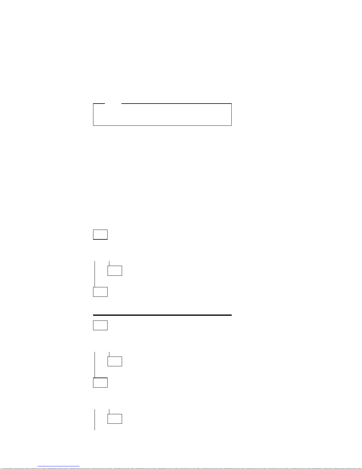
Testing the AC Adapter
1. If a noise can be heard from the AC adapter when it
is plugged into line voltage, replace the AC adapter.
If a noise still comes from the AC adapter, suspect
the computer.
If not, the AC adapter has a problem. Replace the
AC adapter with the original one, then go to the next
step.
2. Measure the output voltage at the plug of the AC
adapter cable.
1
2
If the voltage is not correct, replace the AC adapter.
Testing the Rechargeable Battery
1. Remove the keyboard.
2. Set the rechargeable battery in place without
connecting any external power devices.
3. Measure the voltage between terminals 1 (+) and 2
(−) and note the voltage.
1(+)
4. Using the AC adapter, apply external power to the
computer. Make sure that a charge arrow appears in
the system-status display.
5. Measure the voltage again between terminals
1 (+) and 2 (−).
If the voltage is not greater than the one measured in
Step 3, replace the AC adapter. If the voltage is
greater than the one measured in Step 3, go to the
next step.
Pin Voltage (V dc)
1 +14.3 to +15.8
2 Ground
Model L40 SX (8543) 29
Page 8
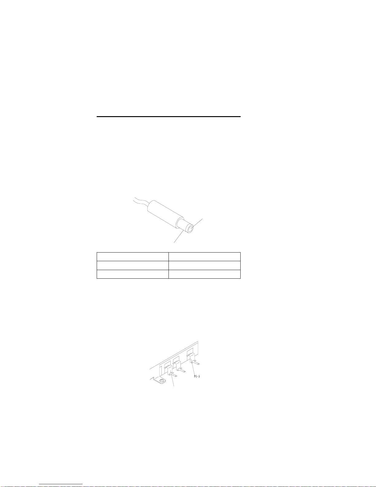
6. Remove the rechargeable battery from the computer.
7. Measure the voltage at the battery terminals.
3( )
2(T)
1(+)
If the voltage is not correct, the rechargeable battery
is discharged or defective. If the voltage is correct,
go to the next step.
8. Using a low-power ohm meter, measure the
resistance at the battery terminals between
2 (T) and 3 (−). The resistance must be
4 kilohms to 30 kilohms.
If the resistance is out of range, replace the
rechargeable battery.
Testing the Backup Battery
1. Remove the keyboard and the top cover.
2. Measure the voltage at the connectors of the backup
battery.
1
2
If the voltage is not correct, the backup battery is
discharged by a short circuit or is defective.
Testing the Standby Battery
Note: The charging time required is 48 hours.
1. Remove the keyboard and the top cover.
2. Connect the AC adapter to the computer.
Pin Voltage (V dc)
1 +8.5 to +12.6
3 Ground
Pin Voltage (V dc)
1 +2.8 to +3.2
2 Ground
30 IBM Mobile Systems HMM - Volume 1
Page 9

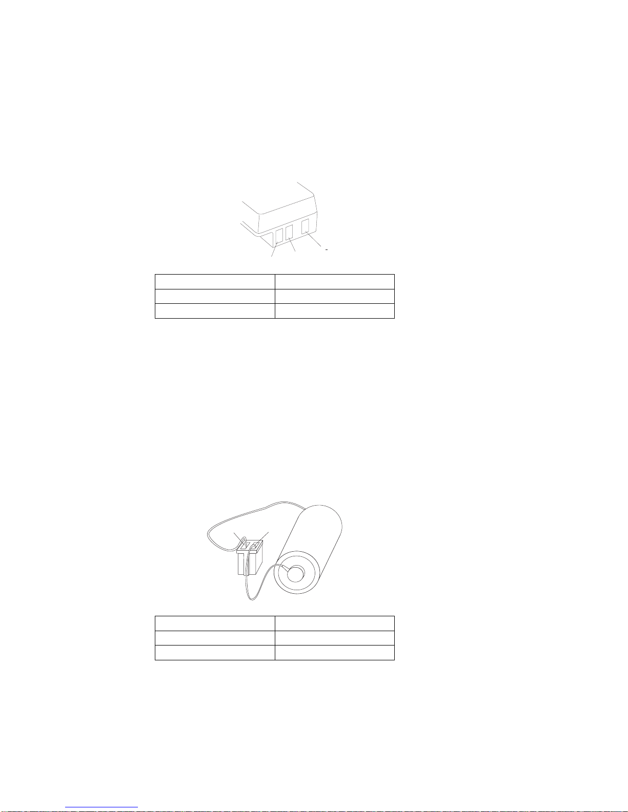
3. Disconnect the standby battery connector from the
system board and measure the voltage at the
connector of the standby battery as shown.
1
2
(Red)
(Black)
If the voltage is correct, perform the failing operation
with a fully-charged standby battery to isolate the
problem.
If the voltage is not correct, continue.
4. Measure the output voltage at the connector on the
system board.
(Top View)
(-) (+)
If the voltage is higher than measured in Step 3, the
standby battery is discharged or is defective.
If the voltage is the same as measured in Step 3 or
less than +3.0 V dc, replace the standby battery. If
the problem remains, replace the system board.
Testing the Quick Charger: If a noise can be
heard from the operating quick charger, replace it.
1. Perform steps 6 through 8 on page 30 of the “Testing
the Rechargeable Battery” to verify the rechargeable
battery for correct operation.
2. Plug the quick charger into an electrical outlet.
If the amber power indicator does not turn on, replace
the quick charger.
3. Install the rechargeable battery.
If the green charging indicator is not blinking, replace
the quick charger.
Pin Voltage (V dc)
1 +3.0 to +4.5
2 Ground
Model L40 SX (8543) 31
Page 10

Symptom-to-FRU Index
The Symptom-to-FRU Index lists symptoms and errors and
the possible causes. The most likely cause is listed first.
If the computer displays an error message, first replace
FRUs listed in the error message. An
X
in an error
message can be any number.
Note: If you have an IBM device with its own service
manual or a device not supported by the advanced
diagnostics tests, refer to the manual for that
device.
Symptom/Error FRU/Action
One or more keys do not
work.
(See “External
Keyboard/Auxiliary Input
Device Checkout” on
page 465 before replacing
any FRUs.)
1. Keyboard
2. System Board
No beep and a blank or
unreadable display during
POST.
(See “Power Systems
Checkout” on page 27
before replacing any FRUs.)
1. System Board
2. Any options or devices
3. Power source when
failing
4. Speaker
No beep with a normal
display during POST.
1. Speaker
2. System Board
Continuous beep 1. System Board
2. Any options or devices
Repeating short beeps.
(See “External
Keyboard/Auxiliary Input
Device Checkout” on
page 465 before replacing
any FRUs.)
1. System Board
2. Keyboard
Dew Point or Temperature
icon appears with one long
and one short beep.
1. System Board
2. Power source when
failing
One long and one short
beep.
1. System Board
2. Power source when
failing
One long and two short
beeps.
1. System Board
2. Power source when
failing
One short beep and a
blank, unreadable, or
flashing display with no
external display attached.
1. Display (LCD)
2. System Board
3. Power source when
failing
One short beep and
Diskette Prompt or a
program load from the hard
disk drive or unable to read
diskette(s).
1. Diskette Drive
2. System Board
3. Diskette Drive Cable
32 IBM Mobile Systems HMM - Volume 1
Page 11

Symptom/Error FRU/Action
Two short beeps and a
blank display.
1. System Board
2. Any options or devices
External display problems.
(See “External Display
Self-Test” on page 464
before replacing any FRUs.)
1. External Display
2. System Board
Incorrect memory size
during POST.
(See “Memory Checkout” on
page 25 before replacing
any FRUs.)
1. System Board
2. Memory Module Kits
Computer hang-up or
intermittent hang-up.
1. System Board
2. Hard Disk Drive
3. Math Coprocessor
4. Replace the last device
being tested
(See “Undetermined
Problem” on page 36.)
Computer does not suspend
or resume.
(Check the Suspend icon to
make sure of the failure.)
1. System Board
2. System-Status
Display Assembly
3. Any options or devices
Computer does not power
off.
1. System-Status
Display Assembly
2. System Board
Real-time clock inaccurate. 1. System Board
Printer problems. 1. See “Printer
Checkout” on
page 468.
Serial or parallel port device
problems.
1. Device
2. Cable
3. System Board
ICON is incorrectly blinking
or stays on.
1. System Board
2. Related Device
ICON incorrectly remains
off, but diagnostics runs
without an error.
1. System Board
2. Related Device
3. System-Status
Display Assembly
Internal Data/Fax Modem
does not communicate with
a remote modem or a fax.
(See “Fax/Modem
Checkout” on page 466
before replacing any FRUs.)
1. Internal Data/Fax
Modem
(Make sure
Data/Fax
Modem power
option is
set to on in the Set
Features program.)
101, 103, 107, 111 1. System Board
2. Hard Disk Drive
3. Diskette Drive
4. Any attached devices
109, 110, 121
(See “Memory Checkout” on
page 25 before replacing
any FRUs.)
1. Memory Module Kits
2. System Board
Model L40 SX (8543) 33
Page 12

Symptom/Error FRU/Action
122, 124 1. System Board
2. Auxiliary Input Device
3. Keyboard
123 1. Hard Disk Drive
2. System Board
3. Hard Disk Drive Cable
141 1. System-Status
Display Assembly
2. System Board
149 1. System Board
2. Hard Disk Drive
3. Hard Disk Drive Cable
161 1. Run Automatic
Configuration
2. Backup Battery
3. System Board
162 1. Run Automatic
Configuration, then
check the installed
devices using the
View configuration
utility.
2. System Board
3. Diskette Drive
4. Hard Disk Drive
5. Math Coprocessor
6. Diskette Drive Cable
7. Hard Disk Drive Cable
163 1. Time and Date Set?
2. System Board
164
(See “Memory Checkout” on
page 25 before replacing
any FRUs.)
1. Run Automatic
Configuration
2. Memory Module Kits
3. System Board
199 1. See “Checking
Installed Devices” on
page 37.
1XX
(not listed above)
1. System Board
211
(on POST)
1. System Board
2. Memory Module Kits
221
(on POST)
1. System Board
204, 214, 224, 240 1. System Board
2. Memory Module Kits
25X 1. System Board
2XX
(not listed above)
(See “Memory Checkout” on
page 25 before replacing
any FRUs.)
1. Memory Module Kits
2. System Board
34 IBM Mobile Systems HMM - Volume 1
Page 13

Symptom/Error FRU/Action
301, 302 1. System Board
2. Keyboard
303 1. System Board
2. Numeric Keypad
3. Keyboard
304, 305
(See “External
Keyboard/Auxiliary Input
Device Checkout” on
page 465 before replacing
any FRUs.)
1. Keyboard
2. System Board
3. Numeric Keypad
306, 310 1. System Board
308 1. Numeric Keypad
3XX
(not listed above)
(See “External
Keyboard/Auxiliary Input
Device Checkout” on
page 465 before replacing
any FRUs.)
1. System Board
2. Auxiliary input device
3. Keyboard
602, 653, 654 1. Defective diskette
2. Diskette Drive
3. System Board
655, 660, 661 1. System Board
6XX
(not listed above)
1. Diskette Drive
2. System Board
3. Diskette Drive Cable
7XX 1. Math Coprocessor
2. System Board
(IBM does not supply a
math coprocessor)
9XX 1. System Board
2. Any parallel Device
3. Communication Cable
1107 1. Communication
Cable
11XX 1. System Board
2. Any serial adapter
3. Communication Cable
1207 1. Communication
Cable
12XX 1. Any serial adapter
2. System Board
3. Any serial device
4. Communication Cable
1705 to 1707, 1709, 1711,
1718 to 1720, 1730, 1732
1. Hard Disk Drive
(Reformatting the hard
disk can recover from
the problem.)
Model L40 SX (8543) 35
Page 14

Symptom/Error FRU/Action
17XX
(not listed above)
1. Hard Disk Drive
2. System Board
3. Hard Disk Drive Cable
24XX 1. System Board
5001 to 5016 1. System Board
5017 to 502X 1. System Board
2. LCD Display Assembly
503X 1. External CRT Display
2. System Board
8601, 8602 1. Pointing Device
2. System Board
3. Numeric Keypad
8604 1. System Board
86XX
(not listed above)
1. System Board
2. Pointing Device
3. Numeric Keypad
101XX
(See “Fax/Modem
Checkout” on page 466
before replacing any FRUs.)
1. Internal Data/Fax
Modem
2. System Board
3. Any serial device
102XX 1. System-Status
Display Assembly
2. System Board
3. Related device
Undetermined Problem
You are here because the diagnostics tests did not identify
the failing FRU.
Check the power supply in use (see “Power Systems
Checkout” on page 27). If the power systems are
operating correctly, return here and continue with the
following procedure.
1. Power-off the computer and remove the battery packs
from the computer.
2. Remove or disconnect one of the following devices or
adapter (do not isolate FRUs that are known to be
good).
a. Non-IBM devices
b. Modem, printer, mouse, or other external device
c. IC DRAM card
d. Hard disk drive (fixed disk drive) or diskette drive
e. Any adapter and device.
3. Power-on the computer and start the system program.
4. If the symptom remains, repeat steps 2 and 3 until
you find the failing FRU or until all FRUs have been
removed.
5. If all of the FRUs listed have been removed and the
problem remains, replace the system board.
36 IBM Mobile Systems HMM - Volume 1
Page 15

Related Service Procedures
Checking Installed Devices
The Installed Devices List shows the presence of devices
in the computer. If an adapter or device is missing from
the list, you might have one of the following conditions.
An adapter or device is defective.
The device missing from the list is an unrecognizable
drive or adapter.
The device missing from the list requires an additional
diskette. (See the device service manual.)
A power supply voltage is incorrect (see “Power
Systems Checkout” on page 27).
If the adapter is on the list, run the adapter diagnostics
tests. If the list contains an adapter or device that is not
installed, go to “Undetermined Problem” on page 36.
Power-on Password
Important
This information is not available in this HMM online
format. See your IBM Servicer or IBM Authorized
Dealer for this procedure.
How to Run Advanced Diagnostics
1. Power-off the computer.
2. Insert the backup copy of the Reference Diskette into
the diskette drive.
3. Power-on the computer.
4. Advance to the Main Menu.
5. Press Ctrl+A to run the System Checkout.
Model L40 SX (8543)
37
Page 16

Product Overview
The following table provides a brief overview of the
computer features.
Feature Description
Processor (MHz) 386SX 20-Mhz
Bus Architecture AT Bus
Memory (Standard) 2MB
Memory (Maximum) 18MB
Video VGA
Diskette Drive 3.5-inch
Hard Drive 60MB
38 IBM Mobile Systems HMM - Volume 1
Page 17

FRU Removals and Replacements
Follow the numerical sequence in the FRU removal
sequence list and the exploded view to remove or
disconnect parts in the correct order. The letters in
parentheses in the list indicate screw types. See the
“Screw Size Chart” on page 19 to match the letters to the
correct screw type and size before replacing each screw.
Safety Notice 8: Translation on page 13
Before removing any FRU, power-off the computer,
unplug all power cords from electrical outlets, remove
the battery pack, then disconnect any interconnecting
cables.
Safety Notice 1: Translation on page 7
Before the computer is powered-on after FRU
replacement, make sure all screws, springs, or other
small parts are in place and are not left loose inside
the computer. Verify this by shaking the computer
and listening for rattling sounds. Metallic parts or
metal flakes can cause electrical shorts.
.1/ Battery Pack
.2/ Three Screw Covers and Three Screws (C)
.3/ Loosen Keyboard Assembly
(Raise front until it clears case.)
.4/ Two Ribbon Cables and Keyboard
(Slide keyboard forward and flip it over in front of
computer.)
.5/ Three Top Cover Screws (C)
(Inside right and left rear access doors along top
edge)
.6/ Two Status Display Ribbon Cables
.7/ Top Cover
(Use small screwdriver to release latch on left side,
if necessary.)
.8/ Two Status Display Screws (F)
(One on each end)
.9/ Status Display Assembly
(contains on/off and power saver switches)
.1ð/ Four Hinge Screws (C)
(Two on each end, inside two rear access doors)
.11/ Left Hinge Cables
.12/ Right Hinge Cables
.13/ LCD Assembly
.14/ Memory Modules
(Do not install two 4MB memory module kits. Install
a 2MB memory module kit in connector 1 and a
4MB or 8MB memory module kit in connector 2.)
.15/ Two Screws (F)
(At front edge of diskette drive)
Model L40 SX (8543) 39
Page 18

.16/ Two Diskette Drive Ribbon Cables
.17/ Diskette Drive and Drive Mounting Bracket
.18/ Standby Battery
.19/ Battery Shield
.2ð/ Backup Battery
.21/ Adapter Bezel
.22/ One Screw (F)
(In corner of serial/modem card)
.23/ Serial/Modem Card
.24/ Two Screws (F)
(At front edge of hard disk drive)
.25/ Two Ribbon Cables and Hard Disk Drive
(Have customer backup all information on hard disk
drive before removal.)
.26/ External Adapter and Battery Doors
.27/ Eight System Board Screws (F)
.28/ One Screw (C)
(Inside right-rear access door)
.29/ Two Threaded Hex Spacers
(Inside right-rear access door)
Remaining System Board Cables
.3ð/ System Board
(When replacing system board, install old memory
module kits and math coprocessor on new system
board. Run Automatic Configuration using
customer's backup Reference Diskette.)
.31/ Speaker
40 IBM Mobile Systems HMM - Volume 1
Page 19

Model L40 Exploded View
31
21
11
30
20
10
1
2
3
4
5
6
7
8
9
22
13
23
14
24
15
25
16
26
17
27
27
18
28
19
29
12
Model L40 SX (8543) 41
Page 20

Locations
System Board
.1/ Suspend/Resume Switch
.2/ Backup Battery Connector
.3/ Battery Contacts
.4/ Standby-Battery Connector
.5/ Diskette-Drive Connectors
.6/ Display Power Connector
.7/ Math Coprocessor Connector
.8/ Memory-Module Connector 1
.9/ Memory-Module Connector 2
.1ð/ Speaker Connector
.11/ Keyboard Connectors
.12/ Password-Override Connector
.13/ Switch-Assembly Connector
.14/ System-Status Display Connector
.15/ Option Connector
.16/ Hard-Disk Drive Connectors
.17/ Display Signal Connectors
.18/ Suspend/Resume Switch Connector
(Top View)
2
3
4 5 6
78902
5
16
17
18
4 3
42 IBM Mobile Systems HMM - Volume 1
Page 21

Parts Listing
1
2
3
4
5
6
7
8
9
10
11
12
14
15
16
13
17
18
Model L40 SX (8543) 43
Page 22

System Unit
DASD
Index
1 Display Assembly (LCD) 95F4878
2 System-Status Display Assembly 79F0991
3 Top Cover 79F3893
4 2MB Memory Module Kit 79F1002
4 4MB Memory Module Kit 79F1003
4 8MB Memory Module Kit 79F1004
6 80387SX** Math Coprocessor 79F1006
7 Bottom Cover 79F3884
8 System Board 95F4879
System Board (with attached speaker) 8123176
9 Speaker 79F0989
Speaker (for p/n 8123176) 79F0989
10 Bezel, Blank 79F3888
10 Bezel, Modem 79F3889
10 Bezel, Serial Adapter 79F3868
11 Backup Battery, Lithium 79F0986
13 Shield, Battery 79F3891
14 Standby Battery 79F0992
15 Door, Bus Connector 79F3886
16 Door, Battery 79F3887
17 Door, I/O Connector 79F3885
18 Rechargeable Battery 79F0994
18 Rechargeable Battery
(Switzerland only)
79F3881
System Board Fuse Card 95F6731
Miscellaneous Kit
(screws, rubber bumpers,
and bottom cover caps)
79F3894
Index
5 Diskette Drive 79F0983
Cable, Diskette Drive 79F0987
Bezel, Diskette Drive 79F3892
12 60MB Hard Disk Drive 79F1009
80MB Hard Disk Drive 95F4714
Cable, Hard Disk Drive 79F0988
**
80387SX is a trademark of the Intel Corporation.
44 IBM Mobile Systems HMM - Volume 1
Page 23

Options and Adapters
2MB Memory Module (80ns) 79F1002
4MB Memory Module (80ns) 79F1003
5.25-inch Drive Adapter/A (360KB/1.2MB) 15F7996
6154 Real-Time Coprocessor (128KB) 60X8192
6166 Real-Time Coprocessor (512KB) 76X1013
8MB Memory Module (80ns) 79F1004
8MB Memory Module Kit (80ns) 64F3607
80386 Memory Expansion Adapter 72X6671
AC Adapter 79F0993
ActionMedia II Display Adapter 69F9731
ActionMedia II Capture Option 69F9735
ActionMedia II Video Cable 69F9737
ActionMedia II Audio/Video Capture Cable 69F9736
ActionMedia II Display CD-ROM Cable 69F9747
Carrying Case 79F3869
Communication Cable (for 79F0996) 94X1540
Data/Fax Modem (U.S., Canada only) 79F0996
Diskette Drive Bus Adapter 72X8524
Enhanced 5250 Emulation Adapter 64G3956
External Diskette Drive Adapter 72X6757
Game Control Adapter 8529151
PC Network Adapter 8286171
PC Network Adapter II 72X8105
PC Network Baseband Adapter 72X8101
PhoneCommunicator Adapter 33F4846
PhoneCommunicator Cable (Black-L) 57F1261
PhoneCommunicator Cable (Black-S) 57F1262
PhoneCommunicator Cable (Beige-L) 57F1263
PhoneCommunicator Cable (Beige-S) 57F1264
Printer Cable 8529214
Quick Charger 79F0995
Realtime Interface Coprocessor 6-Port V.35 72F0164
Screen Reader Adapter 33F4842
Screen Reader Keypad 1393515
Screen Reader Keypad Cable 72X8537
SCSI Adapter/A (with Cache) 85F0063
SCSI Adapter/A (without Cache) 85F0002
SCSI Cable (internal) 64F4127
SDLC Adapter 8286099
Serial Adapter 79F0998
Serial Adapter Cable 8286170
Serial Adapter Connector 8286194
Serial/Parallel Adapter 8286147
SpeechViewer Adapter 15F8511
Strap 07G1449
Token-Ring 16/4 Adapter 93F0334
Token-Ring Adapter 16F0463
Token-Ring Adapter (with RPL Module) 83X7839
Model L40 SX (8543) 45
Page 24

Keyboard
Numeric Keypad and Mouse
Arabic 1396825
Belgian 1396812
Canadian French 1396810
Danish 1396813
Dutch 1396817
French 1396814
German 1396815
Greek 1396826
Hebrew 1396827
Icelandic 1396828
Italian 1396816
Norwegian 1396818
Portuguese 1396819
Spanish 1396820
Spanish Speaking 1396811
Swedish/Finish 1396821
Swiss/French 1396822
Swiss/German 1396823
Turkish 1396829
U.K. English 1396824
U.S. English 1396181
U.S. 1396182
Arabic 1396806
Canadian French 1396800
French 1396801
German 1396802
Greek 1396807
Italian 1396803
Spanish 1396804
Swedish/Finland 1396805
Swiss/French 1396809
Swiss/German 1396808
Trackpoint (Model L40 SX) 1397090
46 IBM Mobile Systems HMM - Volume 1
 Loading...