

Page 1

Power Systems
Site and hardware planning
IBM
Page 2

Page 3

Power Systems
Site and hardware planning
IBM
Page 4

Note
Before using this information and the product it supports, read the information in “Safety notices” on page v, “Notices” on
page 177, the IBM Systems Safety Notices manual, G229-9054, and the IBM Environmental Notices and User Guide, Z125–5823.
This edition applies to IBM Power Systems servers that contain the POWER8 processor and to all associated
models.
© Copyright IBM Corporation 2015, 2016.
US Government Users Restricted Rights – Use, duplication or disclosure restricted by GSA ADP Schedule Contract
with IBM Corp.
Page 5

Contents
Safety notices ................................. v
Site and hardware physical planning overview ................... 1
Planning activities ............................... 3
Planning task checklist ................................ 3
General considerations ................................ 3
Site preparation and physical planning guidelines ....................... 4
Site and hardware planning ........................... 7
Hardware specification sheets ............................. 7
Server specifications ................................ 7
Model 8408-44E and 8408-E8E server specifications .................... 7
Model 8408-44E Technical Documentation for EU Regulation 617/2013 ............ 12
Model 8408-E8E Technical Documentation for EU Regulation 617/2013 ............ 13
Expansion unit and migration tower specifications ..................... 14
5887 expansion unit .............................. 14
EMX0 PCIe Gen3 I/O expansion drawer (feature code EMX0) ................ 15
5147-024, ESLL, and ESLS storage enclosures ...................... 16
Rack specifications ................................ 17
Model 0550 and 9406-830 rack ........................... 18
Model 0551 rack ................................ 19
Model 0551, 0553, 0555, and 7014 rack configurations ................... 21
Model 0551 and 9406-270 rack ........................... 28
Model 0554 and 7014-S11 rack ........................... 30
Model 0555 and 7014-S25 rack ........................... 32
Planning for the 7014-T00 and 7014-T42 racks ...................... 36
Model 7014-T00 rack ............................. 36
Model 7014-T00 rack with optional DC power distribution panel .............. 38
Model 7014-T42, 7014-B42, and 0553 rack ...................... 40
7014-T00, 7014-T42, and 0553 supported feature codes .................. 44
7014-T00, 7014-T00, and 0553 racks multiple attachment ................. 46
7014-T00, 7014-T42, and 0553 rack weight distribution and floor loading ............ 46
Planning for the 7953-94X and 7965-94Y rack ...................... 48
Model 7953-94X and 7965-94Y rack ........................ 48
Cabling the 7953-94X and 7965-94Y rack ....................... 50
Side stabilizing outriggers ........................... 52
Multiple racks ............................... 53
Model 1164-95X rear door heat exchanger ...................... 54
Model 1164-95X rear door heat exchanger water cooling specifications and requirements ...... 57
Planning for the 7965-S42 rack ........................... 61
Model 7965-S42 rack specifications ........................ 61
Cabling the 7965-S42 rack ........................... 65
Multiple racks ............................... 67
Model 7965-S42 supported feature codes....................... 68
Model 1164-95X rear door heat exchanger ...................... 69
Model 1164-95X rear door heat exchanger water cooling specifications and requirements ...... 72
Hardware Management Console specifications....................... 76
7042-C07 desktop Hardware Management Console specifications ............... 76
7042-C08 Hardware Management Console specifications .................. 77
7042-CR7 Hardware Management Console specifications .................. 78
7042-CR8 Hardware Management Console specifications .................. 79
7042-CR9 Hardware Management Console specifications .................. 80
7063-CR1 Hardware Management Console specifications .................. 82
Rack switch specifications ............................. 84
© Copyright IBM Corp. 2015, 2016 iii
Page 6

G8052R RackSwitch specification sheet ........................ 84
G8124ER RackSwitch specification sheet ........................ 84
G8264R RackSwitch specification sheet ........................ 85
G8316R RackSwitch specification sheet ........................ 86
Rack installation specifications for racks not purchased from IBM ................ 86
Planning for power ................................. 93
Determining your power requirements ......................... 93
Server Information Form 3A............................ 94
Workstation Information Form 3B .......................... 95
Plugs and receptacles ............................... 95
Supported power cords ............................. 95
Supported PDU power cords ........................... 105
Modification of IBM-provided power cords ....................... 108
Uninterruptible power supply ............................ 109
Power distribution unit and power cord options for 0551, 0553, 0555, 7014, 7953, and 7965 racks ..... 111
Calculating the power load for 7188 or 9188 power distribution units............... 117
Planning for cables ................................ 119
Cable management ............................... 120
Power cord routing and retention ......................... 121
Planning for serial-attached SCSI cables ........................ 122
SAS cabling for the 5887 disk drive enclosure ..................... 147
SAS cabling for the ESLL and ESLS storage enclosures .................. 164
Planning for high availability.......................... 173
Understanding workloads .............................. 173
Planning for high availability by using Live Partition Mobility (LPM) ............... 173
Planning for high availability by using PowerHA SystemMirror ................. 174
Notices ................................... 177
Accessibility features for IBM Power Systems servers ..................... 178
Privacy policy considerations ............................. 179
Trademarks ................................... 180
Electronic emission notices .............................. 180
Class A Notices................................. 180
Class B Notices ................................. 184
Terms and conditions................................ 187
iv Site and hardware planning
Page 7

Safety notices
Safety notices may be printed throughout this guide:
v DANGER notices call attention to a situation that is potentially lethal or extremely hazardous to
people.
v CAUTION notices call attention to a situation that is potentially hazardous to people because of some
existing condition.
v Attention notices call attention to the possibility of damage to a program, device, system, or data.
World Trade safety information
Several countries require the safety information contained in product publications to be presented in their
national languages. If this requirement applies to your country, safety information documentation is
included in the publications package (such as in printed documentation, on DVD, or as part of the
product) shipped with the product. The documentation contains the safety information in your national
language with references to the U.S. English source. Before using a U.S. English publication to install,
operate, or service this product, you must first become familiar with the related safety information
documentation. You should also refer to the safety information documentation any time you do not
clearly understand any safety information in the U.S. English publications.
Replacement or additional copies of safety information documentation can be obtained by calling the IBM
Hotline at 1-800-300-8751.
German safety information
Das Produkt ist nicht für den Einsatz an Bildschirmarbeitsplätzen im Sinne § 2 der
Bildschirmarbeitsverordnung geeignet.
Laser safety information
IBM®servers can use I/O cards or features that are fiber-optic based and that utilize lasers or LEDs.
Laser compliance
IBM servers may be installed inside or outside of an IT equipment rack.
DANGER: When working on or around the system, observe the following precautions:
Electrical voltage and current from power, telephone, and communication cables are hazardous. To avoid
a shock hazard:
v If IBM supplied the power cord(s), connect power to this unit only with the IBM provided power cord.
Do not use the IBM provided power cord for any other product.
v Do not open or service any power supply assembly.
v Do not connect or disconnect any cables or perform installation, maintenance, or reconfiguration of this
product during an electrical storm.
v The product might be equipped with multiple power cords. To remove all hazardous voltages,
disconnect all power cords.
– For AC power, disconnect all power cords from their AC power source.
– For racks with a DC power distribution panel (PDP), disconnect the customer’s DC power source to
the PDP.
v When connecting power to the product ensure all power cables are properly connected.
© Copyright IBM Corp. 2015, 2016 v
Page 8

– For racks with AC power, connect all power cords to a properly wired and grounded electrical
outlet. Ensure that the outlet supplies proper voltage and phase rotation according to the system
rating plate.
– For racks with a DC power distribution panel (PDP), connect the customer’s DC power source to
the PDP. Ensure that the proper polarity is used when attaching the DC power and DC power
return wiring.
v Connect any equipment that will be attached to this product to properly wired outlets.
v When possible, use one hand only to connect or disconnect signal cables.
v Never turn on any equipment when there is evidence of fire, water, or structural damage.
v Do not attempt to switch on power to the machine until all possible unsafe conditions are corrected.
v Assume that an electrical safety hazard is present. Perform all continuity, grounding, and power checks
specified during the subsystem installation procedures to ensure that the machine meets safety
requirements.
v Do not continue with the inspection if any unsafe conditions are present.
v Before you open the device covers, unless instructed otherwise in the installation and configuration
procedures: Disconnect the attached AC power cords, turn off the applicable circuit breakers located in
the rack power distribution panel (PDP), and disconnect any telecommunications systems, networks,
and modems.
DANGER:
v Connect and disconnect cables as described in the following procedures when installing, moving, or
opening covers on this product or attached devices.
To Disconnect:
1. Turn off everything (unless instructed otherwise).
2. For AC power, remove the power cords from the outlets.
3. For racks with a DC power distribution panel (PDP), turn off the circuit breakers located in the
PDP and remove the power from the Customer's DC power source.
4. Remove the signal cables from the connectors.
5. Remove all cables from the devices.
To Connect:
1. Turn off everything (unless instructed otherwise).
2. Attach all cables to the devices.
3. Attach the signal cables to the connectors.
4. For AC power, attach the power cords to the outlets.
5. For racks with a DC power distribution panel (PDP), restore the power from the Customer's DC
power source and turn on the circuit breakers located in the PDP.
6. Turn on the devices.
Sharp edges, corners and joints may be present in and around the system. Use care when handling
equipment to avoid cuts, scrapes and pinching. (D005)
(R001 part 1 of 2):
DANGER: Observe the following precautions when working on or around your IT rack system:
v Heavy equipment–personal injury or equipment damage might result if mishandled.
v Always lower the leveling pads on the rack cabinet.
v Always install stabilizer brackets on the rack cabinet.
v To avoid hazardous conditions due to uneven mechanical loading, always install the heaviest devices
in the bottom of the rack cabinet. Always install servers and optional devices starting from the bottom
of the rack cabinet.
v Rack-mounted devices are not to be used as shelves or work spaces. Do not place objects on top of
rack-mounted devices. In addition, do not lean on rack mounted devices and do not use them to
stabilize your body position (for example, when working from a ladder).
vi Site and hardware planning
Page 9
v Each rack cabinet might have more than one power cord.
– For AC powered racks, be sure to disconnect all power cords in the rack cabinet when directed to
disconnect power during servicing.
– For racks with a DC power distribution panel (PDP), turn off the circuit breaker that controls the
power to the system unit(s), or disconnect the customer’s DC power source, when directed to
disconnect power during servicing.
v Connect all devices installed in a rack cabinet to power devices installed in the same rack cabinet. Do
not plug a power cord from a device installed in one rack cabinet into a power device installed in a
different rack cabinet.
v An electrical outlet that is not correctly wired could place hazardous voltage on the metal parts of the
system or the devices that attach to the system. It is the responsibility of the customer to ensure that
the outlet is correctly wired and grounded to prevent an electrical shock.
(R001 part 2 of 2):
CAUTION:
v Do not install a unit in a rack where the internal rack ambient temperatures will exceed the
manufacturer's recommended ambient temperature for all your rack-mounted devices.
v Do not install a unit in a rack where the air flow is compromised. Ensure that air flow is not blocked
or reduced on any side, front, or back of a unit used for air flow through the unit.
v Consideration should be given to the connection of the equipment to the supply circuit so that
overloading of the circuits does not compromise the supply wiring or overcurrent protection. To
provide the correct power connection to a rack, refer to the rating labels located on the equipment in
the rack to determine the total power requirement of the supply circuit.
v (For sliding drawers.) Do not pull out or install any drawer or feature if the rack stabilizer brackets are
not attached to the rack. Do not pull out more than one drawer at a time. The rack might become
unstable if you pull out more than one drawer at a time.
v (For fixed drawers.) This drawer is a fixed drawer and must not be moved for servicing unless specified
by the manufacturer. Attempting to move the drawer partially or completely out of the rack might
cause the rack to become unstable or cause the drawer to fall out of the rack.
Safety notices vii
Page 10

CAUTION:
Removing components from the upper positions in the rack cabinet improves rack stability during
relocation. Follow these general guidelines whenever you relocate a populated rack cabinet within a
room or building.
v Reduce the weight of the rack cabinet by removing equipment starting at the top of the rack
cabinet. When possible, restore the rack cabinet to the configuration of the rack cabinet as you
received it. If this configuration is not known, you must observe the following precautions:
– Remove all devices in the 32U position (compliance ID RACK-001 or 22U (compliance ID RR001)
and above.
– Ensure that the heaviest devices are installed in the bottom of the rack cabinet.
– Ensure that there are little-to-no empty U-levels between devices installed in the rack cabinet
below the 32U (compliance ID RACK-001 or 22U (compliance ID RR001) level, unless the
received configuration specifically allowed it.
v If the rack cabinet you are relocating is part of a suite of rack cabinets, detach the rack cabinet from
the suite.
v If the rack cabinet you are relocating was supplied with removable outriggers they must be
reinstalled before the cabinet is relocated.
v Inspect the route that you plan to take to eliminate potential hazards.
v Verify that the route that you choose can support the weight of the loaded rack cabinet. Refer to the
documentation that comes with your rack cabinet for the weight of a loaded rack cabinet.
v Verify that all door openings are at least 760 x 230 mm (30 x 80 in.).
v Ensure that all devices, shelves, drawers, doors, and cables are secure.
v Ensure that the four leveling pads are raised to their highest position.
v Ensure that there is no stabilizer bracket installed on the rack cabinet during movement.
v Do not use a ramp inclined at more than 10 degrees.
v When the rack cabinet is in the new location, complete the following steps:
– Lower the four leveling pads.
– Install stabilizer brackets on the rack cabinet.
– If you removed any devices from the rack cabinet, repopulate the rack cabinet from the lowest
position to the highest position.
v If a long-distance relocation is required, restore the rack cabinet to the configuration of the rack
cabinet as you received it. Pack the rack cabinet in the original packaging material, or equivalent.
Also lower the leveling pads to raise the casters off of the pallet and bolt the rack cabinet to the
pallet.
(R002)
(L001)
DANGER: Hazardous voltage, current, or energy levels are present inside any component that has this
label attached. Do not open any cover or barrier that contains this label. (L001)
(L002)
viii Site and hardware planning
Page 11
DANGER: Rack-mounted devices are not to be used as shelves or work spaces. (L002)
1
2
!
1
2
1 2
3
4
(L003)
or
or
or
Safety notices ix
Page 12
1
2
3
4
or
DANGER: Multiple power cords. The product might be equipped with multiple AC power cords or
multiple DC power cables. To remove all hazardous voltages, disconnect all power cords and power
cables. (L003)
(L007)
CAUTION: A hot surface nearby. (L007)
(L008)
x Site and hardware planning
Page 13

CAUTION: Hazardous moving parts nearby. (L008)
All lasers are certified in the U.S. to conform to the requirements of DHHS 21 CFR Subchapter J for class
1 laser products. Outside the U.S., they are certified to be in compliance with IEC 60825 as a class 1 laser
product. Consult the label on each part for laser certification numbers and approval information.
CAUTION:
This product might contain one or more of the following devices: CD-ROM drive, DVD-ROM drive,
DVD-RAM drive, or laser module, which are Class 1 laser products. Note the following information:
v Do not remove the covers. Removing the covers of the laser product could result in exposure to
hazardous laser radiation. There are no serviceable parts inside the device.
v Use of the controls or adjustments or performance of procedures other than those specified herein
might result in hazardous radiation exposure.
(C026)
CAUTION:
Data processing environments can contain equipment transmitting on system links with laser modules
that operate at greater than Class 1 power levels. For this reason, never look into the end of an optical
fiber cable or open receptacle. Although shining light into one end and looking into the other end of
a disconnected optical fiber to verify the continuity of optic fibers many not injure the eye, this
procedure is potentially dangerous. Therefore, verifying the continuity of optical fibers by shining
light into one end and looking at the other end is not recommended. To verify continuity of a fiber
optic cable, use an optical light source and power meter. (C027)
CAUTION:
This product contains a Class 1M laser. Do not view directly with optical instruments. (C028)
CAUTION:
Some laser products contain an embedded Class 3A or Class 3B laser diode. Note the following
information: laser radiation when open. Do not stare into the beam, do not view directly with optical
instruments, and avoid direct exposure to the beam. (C030)
CAUTION:
The battery contains lithium. To avoid possible explosion, do not burn or charge the battery.
Do Not:
v ___ Throw or immerse into water
v ___ Heat to more than 100°C (212°F)
v ___ Repair or disassemble
Exchange only with the IBM-approved part. Recycle or discard the battery as instructed by local
regulations. In the United States, IBM has a process for the collection of this battery. For information,
call 1-800-426-4333. Have the IBM part number for the battery unit available when you call. (C003)
Safety notices xi
Page 14

CAUTION:
Regarding IBM provided VENDOR LIFT TOOL:
v Operation of LIFT TOOL by authorized personnel only.
v LIFT TOOL intended for use to assist, lift, install, remove units (load) up into rack elevations. It is
not to be used loaded transporting over major ramps nor as a replacement for such designated tools
like pallet jacks, walkies, fork trucks and such related relocation practices. When this is not
practicable, specially trained persons or services must be used (for instance, riggers or movers).
v Read and completely understand the contents of LIFT TOOL operator's manual before using.
Failure to read, understand, obey safety rules, and follow instructions may result in property
damage and/or personal injury. If there are questions, contact the vendor's service and support.
Local paper manual must remain with machine in provided storage sleeve area. Latest revision
manual available on vendor's web site.
v Test verify stabilizer brake function before each use. Do not over-force moving or rolling the LIFT
TOOL with stabilizer brake engaged.
v Do not move LIFT TOOL while platform is raised, except for minor positioning.
v Do not exceed rated load capacity. See LOAD CAPACITY CHART regarding maximum loads at
center versus edge of extended platform.
v Only raise load if properly centered on platform. Do not place more than 200 lb (91 kg) on edge of
sliding platform shelf also considering the load's center of mass/gravity (CoG).
v Do not corner load the platform tilt riser accessory option. Secure platform riser tilt option to main
shelf in all four (4x) locations with provided hardware only, prior to use. Load objects are designed
to slide on/off smooth platforms without appreciable force, so take care not to push or lean. Keep
riser tilt option flat at all times except for final minor adjustment when needed.
v Do not stand under overhanging load.
v Do not use on uneven surface, incline or decline (major ramps).
v Do not stack loads.
v Do not operate while under the influence of drugs or alcohol.
v Do not support ladder against LIFT TOOL.
v Tipping hazard. Do not push or lean against load with raised platform.
v Do not use as a personnel lifting platform or step. No riders.
v Do not stand on any part of lift. Not a step.
v Do not climb on mast.
v Do not operate a damaged or malfunctioning LIFT TOOL machine.
v Crush and pinch point hazard below platform. Only lower load in areas clear of personnel and
obstructions. Keep hands and feet clear during operation.
v No Forks. Never lift or move bare LIFT TOOL MACHINE with pallet truck, jack or fork lift.
v Mast extends higher than platform. Be aware of ceiling height, cable trays, sprinklers, lights, and
other overhead objects.
v Do not leave LIFT TOOL machine unattended with an elevated load.
v Watch and keep hands, fingers, and clothing clear when equipment is in motion.
v Turn Winch with hand power only. If winch handle cannot be cranked easily with one hand, it is
probably over-loaded. Do not continue to turn winch past top or bottom of platform travel.
Excessive unwinding will detach handle and damage cable. Always hold handle when lowering,
unwinding. Always assure self that winch is holding load before releasing winch handle.
v A winch accident could cause serious injury. Not for moving humans. Make certain clicking sound
is heard as the equipment is being raised. Be sure winch is locked in position before releasing
handle. Read instruction page before operating this winch. Never allow winch to unwind freely.
Freewheeling will cause uneven cable wrapping around winch drum, damage cable, and may cause
serious injury. (C048)
Power and cabling information for NEBS (Network Equipment-Building System)
GR-1089-CORE
The following comments apply to the IBM servers that have been designated as conforming to NEBS
(Network Equipment-Building System) GR-1089-CORE:
xii Site and hardware planning
Page 15

The equipment is suitable for installation in the following:
v Network telecommunications facilities
v Locations where the NEC (National Electrical Code) applies
The intrabuilding ports of this equipment are suitable for connection to intrabuilding or unexposed
wiring or cabling only. The intrabuilding ports of this equipment must not be metallically connected to the
interfaces that connect to the OSP (outside plant) or its wiring. These interfaces are designed for use as
intrabuilding interfaces only (Type 2 or Type 4 ports as described in GR-1089-CORE) and require isolation
from the exposed OSP cabling. The addition of primary protectors is not sufficient protection to connect
these interfaces metallically to OSP wiring.
Note: All Ethernet cables must be shielded and grounded at both ends.
The ac-powered system does not require the use of an external surge protection device (SPD).
The dc-powered system employs an isolated DC return (DC-I) design. The DC battery return terminal
shall not be connected to the chassis or frame ground.
The dc-powered system is intended to be installed in a common bonding network (CBN) as described in
GR-1089-CORE.
Safety notices xiii
Page 16

xiv Site and hardware planning
Page 17

Site and hardware physical planning overview
Successful installation requires effective planning of your physical and operational environment. You are
the most valuable resource in site planning because you know where and how your system, and devices
attached to it, will be used.
Site preparation for the complete system is the responsibility of the customer. The primary task of your
site planner is to ensure that each system is installed so that it can operate and be serviced efficiently.
This topic collection provides the basic information you need to plan for your system installation. It
provides an overview of each planning task, as well as valuable reference information useful throughout
the performance of these tasks. Depending on the complexity of the system you ordered and your
existing computing resource, you might not need to perform all the steps noted here.
First, with the help of your systems engineer, sales representative, or with the help of those coordinating
your installation, list the hardware for which you need to plan. Use the summary of your order to help
you when making your list. This list is now your “To Do” list. You can use the Planning task checklist to
assist you.
While you are responsible for planning, vendors, contractors, and your sales representative are also
available to help with any aspect of the planning. For some system units, a customer service
representative will install your system unit and verify correct operation. Some system units are
considered customer-installed. If you are not sure, check with your sales representative.
The physical planning section of this topic collection provides the physical characteristics of many system
units, and associated products. For information on products not included in this topic collection, contact
your sales representative or your authorized dealer.
Before proceeding with planning, ensure that the hardware and software you have chosen meets your
needs. Your sales representative is available to answer questions.
While this information is for hardware planning, the system memory and disk storage needed are a
function of the software to be used, therefore some things to consider are listed below. Information on
software products is generally in or with the software Licensed Program Product itself.
In assessing the adequacy of hardware and software, consider the following:
v Available disk space and system memory for accommodating software, online documentation, and data
(including future growth needs resulting from additional users, more data, and new applications)
v Compatibility of all devices
v Compatibility of software packages with each other and with the hardware configuration
v Adequate redundancy or backup capabilities in hardware and software
v Software portability to the new system, if necessary
v Prerequisites and corequisites of chosen software have been satisfied
v Data to be transferred to the new system
© Copyright IBM Corp. 2015, 2016 1
Page 18

2 Site and hardware planning
Page 19

Planning activities
You can use this information to help you plan the physical installation for your server.
Proper planning for your system will facilitate a smooth installation and fast system start-up. Sales and
installation planning representatives are also available to help you with installation planning.
As part of your planning activity, you will make decisions about where to locate your server and who
will operate the system
Planning task checklist
Use this checklist to document your planning progress.
Working with your sales representative, establish completion dates for each of the tasks. You might want
to review your planning schedule periodically with your sales representative.
Table 1. Planning task checklist
Planning step Person responsible Target date Completion date
Plan your office or computer
room layout (physical planning)
Prepare for power cords and
electrical needs
Prepare for cables and cabling
Create or modify communications
networks
Perform building alterations, as
needed
Prepare maintenance, recovery,
and security plans
Develop an education plan
Order supplies
Prepare for system delivery
General considerations
Planning your system requires attention to the numerous details.
When determining the placement of your system, consider the following:
v Adequate space for the devices.
v Working environment of personnel who will be using the devices (their comfort, ability to access the
devices, supplies, and reference materials).
v Adequate space for maintaining and servicing the devices.
v Physical security requirements necessary for the devices.
v Weight of the devices.
v Heat output of the devices.
v Operating temperature requirements of the devices.
© Copyright IBM Corp. 2015, 2016 3
Page 20

v Humidity requirements of the devices.
v Air flow requirements of the devices.
v Air quality of the location where the devices will be used. For example, excess dust could damage
your system.
Note: The system and devices are designed to operate in normal office environments. Dirty or other
poor environments might damage the system or the devices. You are responsible for providing the
proper operating environment.
v Altitude limitations of the devices.
v Noise emission levels of the devices.
v Any vibration of equipment near where the devices will be placed.
v Paths of power cords.
The following pages contain the information you need to evaluate these considerations.
Site preparation and physical planning guidelines
These guidelines help you prepare your site for the delivery and installation of your server.
Information contained in the Site preparation and physical planning might be helpful for preparing your
data center for the arrival of a server.
The Site preparation and physical planning topic covers the following information:
Site selection, building and space considerations
v Site selection
v Access
v Static electricity and floor resistance
v Space requirements
v Floor construction and floor loading
v Raised floors
v Conductive contamination
v Computer room layout
Site environment, safety, and security
v Vibration and shock
v Lighting
v Acoustics
v Electromagnetic compatibility
v Computer room location
v Material and data storage protection
v Emergency planning for continuous operations
Electrical power and grounding
v General power information
v Power quality
v Voltage and frequency limits
v Power load
v Power source
4 Site and hardware planning
Page 21

v Dual power installations
Air conditioning
v Air conditioning determination
v General guidelines for data centers
v Temperature and humidity design criteria
v Temperature and humidity recording instruments
v Relocation and temporary storage
v Acclimation
v System air distribution
Planning for the installation of rear door heat exchangers
v Planning for the installation of rear door heat exchangers
v Heat exchanger specifications
v Water specifications for the secondary cooling loop
v Water delivery specifications for secondary loops
v Layout and mechanical installation
v Suggested sources for secondary loop components
Communications
v Planning for communications
Planning activities 5
Page 22

6 Site and hardware planning
Page 23
Site and hardware planning
This topic collection provides specifications that site planners can use to assess the physical site and
operational requirements necessary to prepare your site for a new server. This information includes
specifications for servers and expansion units, plugs and receptacles, and cables as well as information
about power-distribution units and uninterruptible power supplies.
Hardware specification sheets
Hardware specification sheets provide detailed information for your hardware, including dimensions,
electrical, power, temperature, environment, and service clearances.
Server specifications
Server specifications provide detailed information for your server, including dimensions, electrical, power,
temperature, environment, and service clearances.
Select the appropriate models to view the specifications for your server.
Model 8408-44E and 8408-E8E server specifications
Server specifications provide detailed information for your server, including dimensions, electrical, power,
temperature, environment, and service clearances.
Use the following specifications to plan for your server.
Note: Due to special safety and servicing considerations, IBM does not support installation of 8408-44E
or 8408-E8E server nodes higher than the EIA 29 position (location of the rail that supports the
rack-mounted server) in any IBM or non-IBM rack. These special considerations include, but are not
limited to, requirements for multiple service personnel during installation, additional required equipment
such as an IBM approved lift tool and OSHA approved, non-conductive ladders, as well as specialized
instructions.
Table 2. Dimensions for the 8408-44E and 8408-E8E
Width Depth Height EIA units Weight
448 mm (17.6 in.) 776 mm (30.6 in.) 175 mm (6.9 in.) 4 69 kg (152 lb)
1. Preliminary data is subject to change.
Table 3. Shipping dimensions for the 8408-44E and 8408-E8E (including pallet)
Width Depth Height Weight
1080 mm (42.5 in.) 635 mm (25.0 in.) 489 mm (19.25 in.) 94.8 kg (209 lb)
1. Preliminary data is subject to change.
Table 4. Electrical characteristics for the 8408-44E and 8408-E8E
Electrical characteristics Properties
AC rated voltage and frequency
DC rated voltage 192 - 400 V dc (FC EB2N) (8408-E8E)
2,5
1
1
1, 7
200 - 240 V ac at 50 or 60 Hz plus or minus 3 Hz (FC
EB2M)
© Copyright IBM Corp. 2015, 2016 7
Page 24
Table 4. Electrical characteristics for the 8408-44E and 8408-E8E
1, 7
(continued)
Electrical characteristics Properties
Thermal output (maximum)
3,6
11940 BTU/hr (8408-E8E)
13140 BTU/hr (8408-44E)
Maximum power consumption
3,6
3500 W (8408-E8E)
3850 W (8408-44E)
Maximum kVA
4,6
3.57 (8408-E8E)
3.9 (8408-44E)
Phase Single
Notes:
1. Normal operation with four power supplies. Each power supply has an IEC 320 C20 inlet. If your system uses
two PDUs for redundancy, plug power supplies E1 and E2 to PDU A and power supplies E3 and E4 to PDU B.
2. The power supplies automatically accept any voltage with the published, rated-voltage range. If multiple power
supplies are installed and operating, the power supplies draw approximately equal current from the utility
(electrical supply) and provide approximately equal current to the load.
3. Power draw and heat load vary greatly by configuration. When you plan for an electrical system, it is important
to use the maximum values. However, when you plan for heat load, you can use the IBM Systems Energy
Estimator to obtain a heat output estimate based on a specific configuration. For more information, see The IBM
Systems Energy Estimator website.
4. To calculate the amperage, multiply the kVA by 1000 and divide that number by the operating voltage.
5. Model 8408-E8E and 8408-44E uses four power supply units. Current is shared between the four power supply
units during normal system operation.
6. When operating on only two power supplies, over subscription is not available. In this situation, the maximum
values are 3100 W, 3.16 kVA, and 10580 BTU/hr for the 8408-E8E and 3950 W, 4.0 kVA, and 13481 BTU/hr for
the 8408-44E.
7. AC and HVDC power supplies cannot be mixed in the same server or I/O drawer. IBM recommends that AC
products and HVDC products with HVDC PDUs are installed in separate racks. However, AC and HVDC
products can be supported in the same rack if all grounding (earthing) is done in accordance with the applicable
electrical code or codes. IBM provides documentation for different AC and HVDC products about the
disconnecting means for service. If a different disconnecting means is to be used for service of the equipment in
a rack with AC-powered and DC-powered products, the disconnecting means must be made clear to service.
Table 5. Environment requirements
Environment requirements
Environment (operating)
Properties Recommended Allowable
1
2,3,4
ASHRAE class A3 (Fourth edition)
Airflow direction Front-to-back
Temperature 18.0°C – 27.0°C (64.4°F – 80.6°F) 5.0°C – 40.0°C (41.0°F – 104.0°F)
Low end moisture -9.0°C (15.8°F) dew point -12.0°C (10.4°F) dew point and 8%
relative humidity
High end moisture 60% relative humidity and 15°C
(59°F) dew point
85% relative humidity and 24.0°C
(75.2°F) dew point
Maximum altitude 3050 m (10,000 ft)
Allowable environment (nonoperating)
5
Temperature 5°C - 45°C (45°F - 113°F)
Relative humidity 8% to 85%
Maximum dew point 27.0°C (80.6°F)
8 Site and hardware planning
Page 25
Table 5. Environment requirements (continued)
Environment requirements
Environment (shipping)
6
Temperature -40.0°C to 60.0°C (-40°F to 140°F)
Relative humidity 5% - 100% (no condensation)
Maximum wet bulb temperature 29.0°C (84.2°F)
Environment (storage)
Temperature 1°C - 60°C (33.8°F - 140°F)
Relative humidity 5% - 80% (no condensation)
Maximum wet bulb temperature 29.0°C (84.2°F)
Notes:
1. IBM provides the recommended operating environment as the long-term operating environment that can result
in the greatest reliability, energy efficiency, and reliability. The allowable operating environment represents where
the equipment is tested to verify functionality. Due to the stresses that operating in the allowable envelope can
place on the equipment, these envelopes must be used for short-term operation, not continuous operation.
2. Must derate the maximum allowable temperature 1°C (1.8°F) per 175 m (574 ft) above 900 m (2953 ft) up to a
maximum allowable elevation of 3050 m (10000 ft).
3. The minimum humidity level is the larger absolute humidity of the -12°C (10.4°F) dew point and the 8% relative
humidity. These levels intersect at approximately 25°C (77°F). Below this intersection, the dew point (-12°C)
represents the minimum moisture level, while above it, the relative humidity (8%) is the minimum. For the
upper moisture limit, the limit is the minimum absolute humidity of the dew point and relative humidity that is
stated.
4. The following minimum requirements apply to data centers that are operated at low relative humidity:
v Data centers that have do not have ESD floors and where people are allowed to wear non-ESD shoes might
want to consider increasing humidity given that the risk of generating 8 kV increases slightly at 8% relative
humidity, when compared to 25% relative humidity.
v All mobile furnishings and equipment must be made of conductive or static dissipative materials and be
bonded to ground.
v During maintenance on any hardware, a properly functioning and grounded wrist strap must be used by any
personnel who comes in contact with information technology (IT) equipment.
5. Equipment that is removed from the original shipping container and is installed, but is powered down. The
allowable non-operating environment is provided to define the environmental range that an unpowered system
can experience short term without being damaged.
6. If one or more feature codes that are listed in Table 6 are installed in your system, then the maximum wet bulb
temperature is 28°C (82°F).
Table 6. Supported feature codes that affect environmental requirements
1
Feature codes (FCs) Feature code names
1738 / EQ38 856 GB (IBM i) 10K RPM SAS HDD (Gen2-S)
1752 / EQ52 900 GB (AIX®/Linux) 10K RPM SAS HDD (Gen2-S)
1917 / 1866 146 GB (AIX/Linux) 15K RPM SAS HDD (Gen2-S)
1925 / 1869 300 GB (AIX/Linux) 10K RPM SAS HDD (Gen2-S)
1947 / 1868 139 GB (IBM i) 15K RPM SAS HDD (Gen2-S)
1948 / 1927 283 GB (IBM i) 15K RPM SAS HDD (Gen2-S)
1953 / 1929 300 GB (AIX/Linux) 15K RPM SAS HDD (Gen2-S)
1956 / 1844 283 GB (IBM i) 10K RPM SAS HDD (Gen2-S)
1962 / 1817 571 GB (IBM i) 10K RPM SAS HDD (Gen2-S)
1964 / 1818 600 GB (AIX/Linux) 10K RPM SAS HDD (Gen2-S)
Site and hardware planning 9
Page 26
Table 6. Supported feature codes that affect environmental requirements1(continued)
Feature codes (FCs) Feature code names
ESD2 / EQD2 1.14 TB (IBM i) 10K RPM SAS HDD (Gen2-S)
ESD3 / EQD3 1.2 TB (AIX/Linux) 10K RPM SAS HDD (Gen2-S)
ESDU 139 GB (IBM i) 15K RPM SAS HDD (Gen3)
ESDT 146 GB (AIX/Linux) 15K RPM SAS HDD (Gen3)
ESDA 283 GB (IBM i) 15K RPM SAS HDD (Gen3)
ESDB 300 GB (AIX/Linux) 15K RPM SAS HDD (Gen3)
ESDS 283 GB (IBM i) 10K RPM SAS HDD (Gen3)
ESDR 300 GB (AIX/Linux) 10K RPM SAS HDD (Gen3)
ESD4 571 GB (IBM i) 10K RPM SAS HDD (Gen3)
ESD5 600 GB (AIX/Linux) 10K RPM SAS HDD (Gen3)
ESD8 1.14 TB (IBM i) 10K RPM SAS HDD (Gen3)
ESD9 1.2 TB (AIX/Linux) 10K RPM SAS HDD (Gen3)
ESEY 283 GB (IBM i) 15K RPM 4KN SAS HDD (Gen2-S)
ESEZ 300 GB (AIX/Linux) 15K RPM 4KN SAS HDD (Gen2-S)
ESFA 283 GB (IBM i) 15K RPM 4KN SAS HDD (Gen3)
ESFB 300 GB (AIX/Linux) 15K RPM 4KN SAS HDD (Gen3)
ESFE 571 GB (IBM i) 15K RPM 4KN SAS HDD (Gen3)
ESFF 600 GB (AIX/Linux) 15K RPM 4KN SAS HDD (Gen3)
ESFN 571 GB (IBM i) 15K RPM 4KN SAS HDD (Gen2-S)
ESFP 600 GB (AIX/Linux) 15K RPM 4KN SAS HDD (Gen2-S)
ESDE 571 GB (IBM i) 15K RPM SAS HDD (Gen3)
ESDF 600 GB (AIX/Linux) 15K RPM SAS HDD (Gen3)
ESDN 571 GB (IBM i) 15K RPM SAS HDD (Gen2-S)
ESDP 600 GB (AIX/Linux) 15K RPM SAS HDD (Gen2-S)
Note:
1. Any feature code that is listed in this table and is installed in your system decreases the maximum wet bulb
temperature that is allowed during shipping from 29°C (84°F) to 28°C (82°F).
Table 7. Noise emissions for the 8408-44E
Product description
Declared A-weighted sound power level,
L
(B)
Wad
Operating Idle Operating Idle
Model 8408-44E
(2-socket) with a
typical workload
7.6
4
(25°C (77°F), 500 m
(1640 ft.)).
Model 8408-44E
(2-socket) with a
typical workload with
acoustical doors (25°C
7.0 6.5 56 47
(77°F), 500 m (1640
ft.)).
10 Site and hardware planning
1, 2, 3
Declared A-weighted sound pressure level,
L
(dB)
pAm
7.2 60 54
Page 27
Table 7. Noise emissions for the 8408-44E
Product description
Declared A-weighted sound power level,
L
(B)
Wad
1, 2, 3
(continued)
Declared A-weighted sound pressure level,
L
(dB)
pAm
Model 8408-44E
(4-socket) with a
typical workload
8.0
4
7.2 62 54
(25°C (77°F), 500 m
(1640 ft.)).
Model 8408-44E
(4-socket) with a
maximum workload
8.8
4
8.8
4
70 70
(25°C (77°F), 500 m
(1640 ft.)).
Model 8408-44E
(4-socket) with a
maximum workload
9.7
4
9.7
4
79 79
(35°C (95°F), 3050 m
(10000 ft.)).
Model 8408-44E
(4-socket) with a
maximum workload
with acoustical doors
8.9
4
8.9
4
73 73
(35°C (95°F), 3050 m
(10000 ft.)).
Notes:
1. Declared level L
is the upper-limit A-weighted sound power level. Declared level L
Wad
is the mean
pAm
A-weighted emission sound pressure level that is measured at the 1-meter bystander positions.
2. All measurements made in conformance with ISO 7779 and declared in conformance with ISO 9296.
3. 10 dB (decibel) equals 1 B (bel).
4. Notice: Government regulations (such as those prescribed by OSHA or European Community Directives) might
govern noise level exposure in the workplace and might apply to you and your server installation. This IBM
system is available with an optional acoustical door feature that can help reduce the noise that is emitted from
this system. The actual sound pressure levels in your installation depend upon various factors, including the
number of racks in the installation; the size, materials, and configuration of the room where you designate the
racks to be installed; the noise levels from other equipment; the room ambient temperature, and employees'
location in relation to the equipment. Further, compliance with such government regulations also depends upon
various extra factors, including the duration of employees' exposure and whether employees wear hearing
protection. IBM recommends that you consult with qualified experts in this field to determine whether you are
in compliance with the applicable regulations.
Table 8. Noise emissions for the 8408-E8E
Product description
Declared A-weighted sound power level,
L
(B)
Wad
Operating Idle Operating Idle
Model 8408-E8E
(2-socket) with a
typical workload
7.6
4
(25°C (77°F), 500 m
(1640 ft.)).
Model 8408-E8E
(4-socket) with a
maximum workload
8.1
4
(25°C (77°F), 500 m
(1640 ft.)).
1, 2, 3
7.6
8.1
Declared A-weighted sound pressure level,
L
(dB)
pAm
4
4
60 60
65 65
Site and hardware planning 11
Page 28
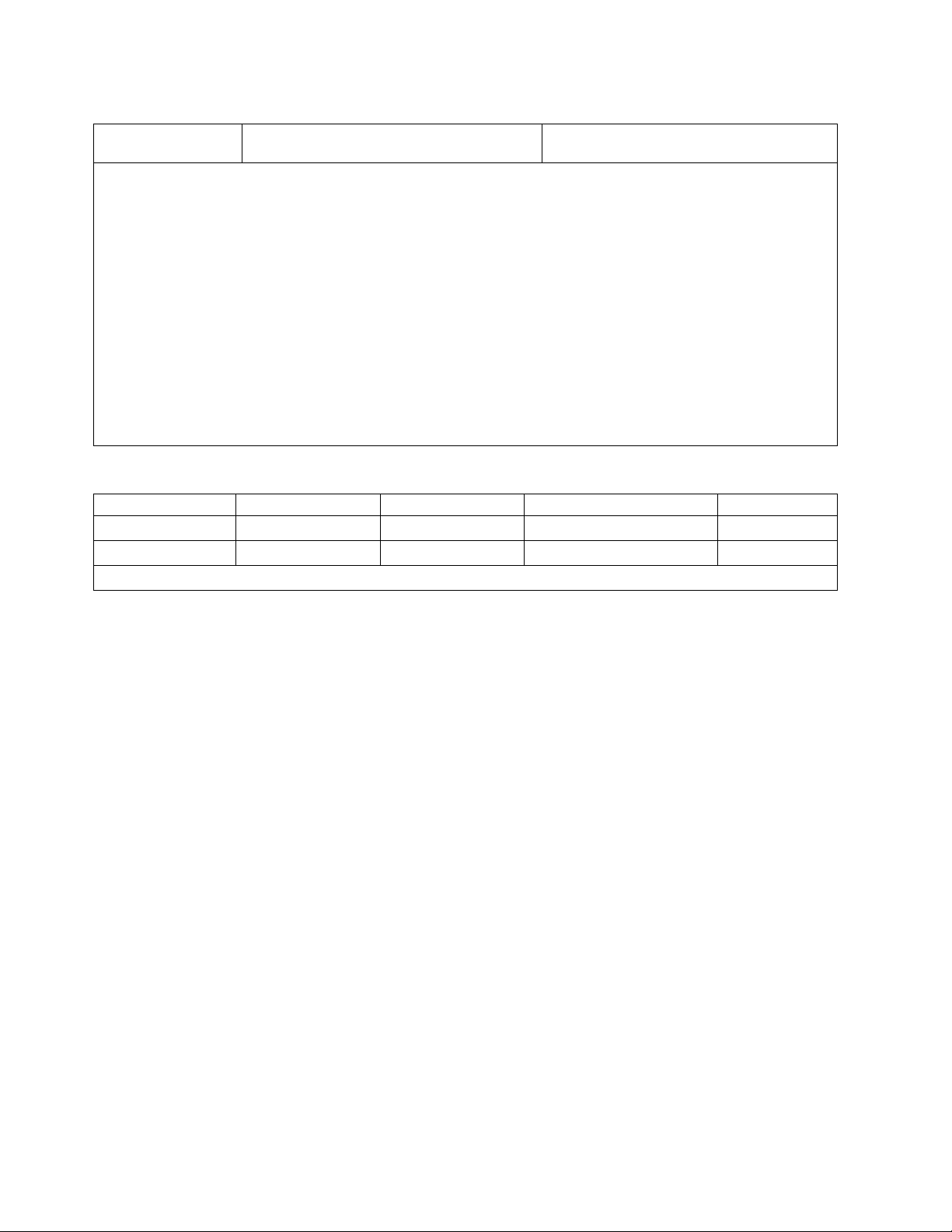
Table 8. Noise emissions for the 8408-E8E
Product description
Declared A-weighted sound power level,
L
(B)
Wad
1, 2, 3
(continued)
Declared A-weighted sound pressure level,
L
(dB)
pAm
Notes:
1. Declared level L
is the upper-limit A-weighted sound power level. Declared level L
Wad
is the mean
pAm
A-weighted emission sound pressure level that is measured at the 1-meter bystander positions.
2. All measurements made in conformance with ISO 7779 and declared in conformance with ISO 9296.
3. 10 dB (decibel) equals 1 B (bel).
4. Notice: Government regulations (such as those prescribed by OSHA or European Community Directives) might
govern noise level exposure in the workplace and might apply to you and your server installation. This IBM
system is available with an optional acoustical door feature that can help reduce the noise that is emitted from
this system. The actual sound pressure levels in your installation depend upon various factors, including the
number of racks in the installation; the size, materials, and configuration of the room where you designate the
racks to be installed; the noise levels from other equipment; the room ambient temperature, and employees'
location in relation to the equipment. Further, compliance with such government regulations also depends upon
various extra factors, including the duration of employees' exposure and whether employees wear hearing
protection. IBM recommends that you consult with qualified experts in this field to determine whether you are
in compliance with the applicable regulations.
Table 9. Service clearances
Clearances Front Rear Side
1
Top
1
Operating 762 mm (30 in.) 762 mm (30 in.)
Nonoperating 762 mm (30 in.) 762 mm (30 in.) 762 mm (30 in.) 762 mm (30 in.)
1
Side and top clearances are optional during operation.
Electromagnetic compatibility compliance: CISPR 22; CISPR 24; FCC, CFR 47, Part 15 (US); VCCI
(Japan); Directive 2004/108/EC (EEA); ICES-003, Issue 4 (Canada); ACMA radio communications
standard (Australia, New Zealand); CNS 13438 (Taiwan); Radio Waves Act, MIC Rule No. 210 (Korea);
Commodity Inspection Law (China); TCVN 7189 (Vietnam); MoCI (Saudi Arabia); SI 961 (Israel); GOST R
51318.22, 51318.24 (Russia)
Safety compliance: UL 60950-1:2007 Underwriters Laboratory; CAN/CSA22.2 No. 60950-1-07;
EN60950-1:2006 European Norm; IEC 60950-1 2nd Edition and all National Differences
Special Hardware Management Console considerations
When the server is managed by an HMC, the console must be provided within the same room and
within 8 m (26 ft) of the server. For more considerations, see Installing and configuring the HMC.
Note: As an alternative to the local HMC requirement, you can provide a supported device, such as a
PC, with connectivity and authority to operate through a remotely attached HMC. This local device must
be in the same room and within 8 m (26 ft) of your server. This local device must provide functional
capabilities that are equivalent to the HMC that it replaces. This local device is needed by the service
representative to service the system.
Model 8408-44E Technical Documentation for EU Regulation 617/2013:
International Business Machines Corporation
New Orchard Road
Armonk, New York 10504
http://www.ibm.com/customersupport/
12 Site and hardware planning
Page 29

Table 10. System characteristics
System characteristics Properties
Product type Computer server
Year first manufactured 2016
Noise levels (declared A-weighted sound power
level of the computer)
8.1 bels (B)
Table 11. Power characteristics.
Power characteristics Properties
Internal/external power supply efficiency 80 PLUS Verification and Testing Report 1025 W
80 PLUS Verification and Testing Report 2000 W
Maximum power (watts) 3850 W
Idle state power (watts) 1559 W (maximum configured system)
Sleep mode power (watts) N/A for servers
Off mode power (watts) 50 W
Table 12. Test parameters for measurements
Test parameters Properties
Test voltage and frequency 230 V ac at 50 Hz or 60 Hz
Total harmonic distortion of the electricity
supply system
The maximum harmonic content of the input voltage waveform is
equal to or less than 2%. The qualification is compliant with EN
61000-3-2.
Information and documentation on the
instrumentation setup and circuits that are used
for electrical testing
Measurement methodology that is used to
determine information in this document
ENERGY STAR Test Method for Computer Servers; ECOVA
Generalized Test Protocol for Calculating the Energy Efficiency of
Internal Ac-Dc and Dc-Dc Power Supplies
ENERGY STAR Servers Version 2.0 Program Requirements;
ECOVA Generalized Test Protocol for Calculating the Energy
Efficiency of Internal Ac-Dc and Dc-Dc Power Supplies
Model 8408-E8E Technical Documentation for EU Regulation 617/2013:
International Business Machines Corporation
New Orchard Road
Armonk, New York 10504
http://www.ibm.com/customersupport/
Table 13. System characteristics
System characteristics Properties
Product type Computer server
Year first manufactured 2015
Noise levels (declared A-weighted sound power
level of the computer)
Table 14. Power characteristics
1
Power characteristics Properties
Internal/external power supply efficiency 80 PLUS Verification and Testing Report 1400 W
Maximum power (watts) 3420 W
8.1 bels (B)
Site and hardware planning 13
Page 30
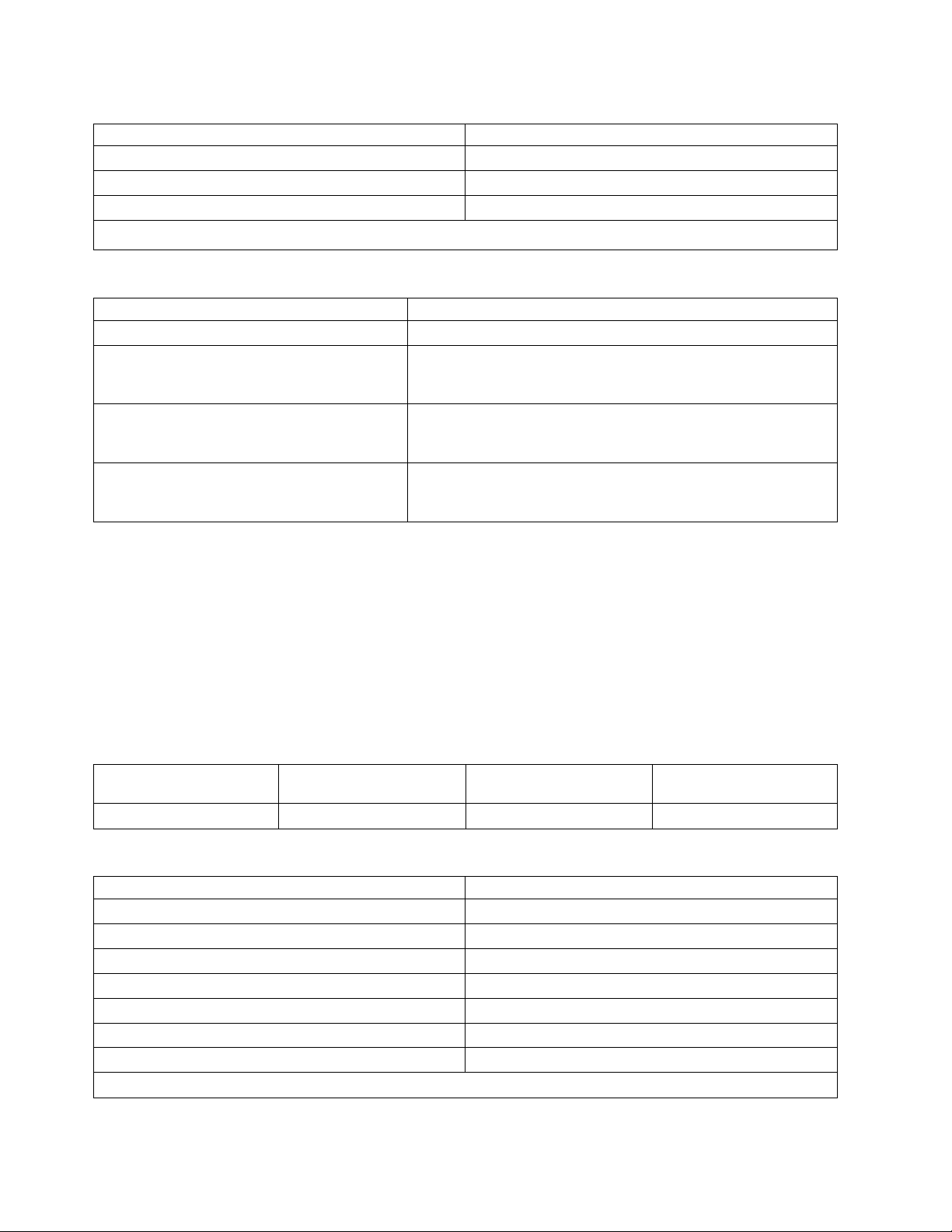
Table 14. Power characteristics1(continued)
Power characteristics Properties
Idle state power (watts) 1449 W
Sleep mode power (watts) N/A for servers
Off mode power (watts) 45 W
1. Preliminary data is subject to change.
Table 15. Test parameters for measurements
Test parameters Properties
Test voltage and frequency 230 V ac at 50 Hz or 60 Hz
Total harmonic distortion of the electricity
supply system
Information and documentation on the
instrumentation setup and circuits that are used
for electrical testing
Measurement methodology that is used to
determine information in this document
The maximum harmonic content of the input voltage waveform is
equal to or less than 2%. The qualification is compliant with EN
61000-3-2.
ENERGY STAR Test Method for Computer Servers; ECOVA
Generalized Test Protocol for Calculating the Energy Efficiency of
Internal Ac-Dc and Dc-Dc Power Supplies
ENERGY STAR Servers Version 2.0 Program Requirements;
ECOVA Generalized Test Protocol for Calculating the Energy
Efficiency of Internal Ac-Dc and Dc-Dc Power Supplies
Expansion unit and migration tower specifications
Expansion unit and migration tower specifications provide detailed information for your hardware,
including dimensions, electrical, power, temperature, environment, and service clearances.
Select a model to view its specifications.
5887 expansion unit
Hardware specifications provide detailed information for your expansion unit, including dimensions,
electrical, power, temperature, environment, and service clearances.
Table 16. Dimensions for rack-mounted expansion unit
Weight (with drives
installed) Width
25.4 kg (56.0 lb) 448.6 mm (17.7 in.) 530 mm (20.9 in.) 87.4 mm (3.4 in.)
Table 17. Electrical
Electrical characteristics Properties
kVA (maximum)
Rated voltage and frequency 100 - 127 V ac or 200 - 240 V ac at 50 - 60 Hz
Thermal output (maximum)
Power requirements (maximum) 300 W
Power factor 0.94
Leakage current (maximum) 1.2 mA
Phase 1
1
All measurements made in conformance with ISO 7779 and declared in conformance with ISO 9296.
1
1
Depth (including front
bezel) Height (with support rails)
0.32
1024 Btu/hr
14 Site and hardware planning
Page 31

Table 18. Temperature requirements
Operating Nonoperating
10°C - 38°C (50°F - 100.4°F)
1
The maximum 38°C (100.4°F) temperature must be derated 1°C (1.8 °F) per 137 m (450 ft) above 1295 m (4250 ft).
1
-40°C - 60°C (-40°F - 140°F)
Table 19. Environmental requirements
Environment Operating Nonoperating Maximum altitude
Noncondensing humidity 20% - 80% (allowable)
40% - 55% (recommended)
8% - 80% (including
condensing)
2134 m (7000 ft) above sea
level
Wet bulb temperature 21°C (69.8°F) 27°C (80.6°F)
Table 20. Noise emissions
1
Properties Operating Idle
L
WAd
L
(1-meter bystander) 43 dB 43 dB
pAm
1
Single drawer in standard 19-inch rack with 24 hard drives, nominal environmental conditions, and no front or rear
6.0 bels 6.0 bels
doors on rack.
For a description of noise emission values, see Acoustics.
All measurements made in conformance with ISO 7779 and declared in conformance with ISO 9296.
Table 21. Service clearances for rack-mounted expansion unit
Front Back Sides
914 mm (36 in.) 914 mm (36 in.) 914 mm (36 in.)
Side and top clearances are optional during operation.
Safety compliance: This hardware is designed and certified to meet the following safety standards: UL
60950; CAN/CSA C22.2 No. 60950–00; EN 60950; IEC 60950 including all National Differences
EMX0 PCIe Gen3 I/O expansion drawer (feature code EMX0)
Hardware specifications provide detailed information for your expansion unit, including dimensions,
electrical, power, temperature, environment, and service clearances.
Table 22. Dimensions for rack-mounted expansion unit
Width Depth Height Weight (maximum)
482 mm (19 in.) 802 mm (31.6 in.)
Table 23. Electrical
1,2,3
173 mm (6.8 in.), 4 EIA
units
54.4 kg (120 lb)
Electrical characteristics Properties
AC rated voltage and frequency 100 - 127 V ac or 200 - 240 V ac at 50 or 60 Hz plus or
minus 3 Hz (FC EMXA)
DC rated voltage 192 - 400 V dc (FC EMXB)
Thermal output (maximum) 1740 BTU/hr
Maximum power consumption 510 W
Maximum kVA 0.520
Site and hardware planning 15
Page 32

Table 23. Electrical
Electrical characteristics Properties
Phase Single
Notes:
1. The power supplies for AC or DC voltage do not change. Only the power chunnel is different. The power
chunnel uses internal cables to carry power from the rear of the system node to the power supplies that are in
the front of the system node.
2. All measurements made in conformance with ISO 7779 and declared in conformance with ISO 9296.
3. AC and HVDC power supplies cannot be mixed in the same server or I/O drawer. IBM recommends that AC
products and HVDC products with HVDC PDUs are installed in separate racks. However, AC and HVDC
products can be supported in the same rack if all grounding (earthing) is done in accordance with the applicable
electrical code or codes. IBM provides documentation for different AC and HVDC products about the
disconnecting means for service. If a different disconnecting means is to be used for service of the equipment in
a rack with AC-powered and DC-powered products, the disconnecting means must be made clear to service.
Table 24. Environment requirements
Environment Recommended operating Allowable operating Nonoperating
ASHRAE class A3
Airflow direction Front-to-back
Temperature
Humidity range 5.5°C (42°F) dew point (DP)
Maximum dew point 24°C (75°F) 27°C (80°F)
Maximum operating
altitude
Shipping temperature -40°C to 60°C (-40°F to
Shipping relative humidity 5% - 100%
1,2,3
(continued)
1
18°C - 27°C (64°F - 80°F) 5°C - 40°C (41°F - 104°F) 1°C - 60°C (34°F - 140°F)
to 60% relative humidity
(RH) and 15°C (59°F) dew
point
-12.0°C (10.4°F) DP and 8%
- 80% RH
3050 m (10000 ft)
5% - 80% RH
140°F)
1. Derate maximum allowable dry-bulb temperature 1°C per 175 m above 950 m.
Table 25. Service clearances for rack-mounted expansion unit
Front Back Sides
914 mm (36 in.) 914 mm (36 in.) 914 mm (36 in.)
Side and top clearances are optional during operation.
Safety compliance: This hardware is designed and certified to meet the following safety standards: UL
60950; CAN/CSA C22.2 No. 60950–00; EN 60950; IEC 60950 including all National Differences.
5147-024, ESLL, and ESLS storage enclosures
Hardware specifications for 5147-024, ESLL, and ESLS storage enclosures provide detailed information for
your storage enclosures, including dimensions, electrical, power, temperature, environment, and service
clearances.
16 Site and hardware planning
Page 33

Table 26. Dimensions for storage enclosures
Weight (maximum
Width Depth Height
448.6 mm (17.7 in.) 744.22 mm (29.3 in.) 87.4 mm (3.4 in.)
Table 27. Electrical characteristics
Electrical characteristics Properties
AC rated voltage and frequency 100 - 127 V ac or 200 - 240 V ac at 50 or 60 Hz plus or
minus 3 Hz
Thermal output (maximum) 939 BTU/hr
Maximum power consumption 275 W
Maximum kVA 0.28
Phase Single
Table 28. Environment requirements
Environment Recommended operating Allowable operating Nonoperating
ASHRAE class A3
Airflow direction Front-to-back
Temperature
Humidity range 5.5°C (42°F) dew point (DP)
Maximum dew point 24°C (75°F) 27°C (80°F)
Maximum operating
altitude
Shipping temperature -40°C to 60°C (-40°F to
Shipping relative humidity 5% - 100%
1
18°C - 27°C (64°F - 80°F) 5°C - 40°C (41°F - 104°F) 1°C - 60°C (34°F - 140°F)
-12.0°C (10.4°F) DP and 8%
to 60% relative humidity
(RH) and 15°C (59°F) dew
point
- 80% RH
3050 m (10000 ft)
configuration)
37.1 kg (81.8 lb) (ESLL)
31.1 kg (68.6 lb) (5147-024
or ESLS)
5% - 80% RH
140°F)
1. Derate maximum allowable dry-bulb temperature 1°C per 175 m above 950 m.
Table 29. Service clearances for rack-mounted expansion unit
Front Back Sides
914 mm (36 in.) 914 mm (36 in.) 914 mm (36 in.)
Side and top clearances are optional during operation.
Safety compliance: This hardware is designed and certified to meet the following safety standards: UL
60950; CAN/CSA C22.2 No. 60950–00; EN 60950; IEC 60950 including all National Differences.
Rack specifications
Rack specifications provide detailed information for your rack, including dimensions, electrical, power,
temperature, environment, and service clearances.
For non-IBM rack specifications, see Rack installation procedures for racks not purchased at IBM.
Site and hardware planning 17
Page 34

Select your rack model to view its specifications.
Model 0550 and 9406-830 rack
Rack specifications provide detailed information for your rack, including dimensions, electrical, power,
temperature, environment, and service clearances.
Figure 1. 0550 rack
Figure 2. 0550 rack configuration
Table 30. Dimensions
Maximum
configuration weight
644 kg (1417 lb) 650 mm (25.5 in.) 1020 mm (40.0 in. ) 1800 mm (71.0 in. ) 36
The 1.8 meter rack has 10 EIA units of space remaining. This space will be filled with a 5 EIA filler panel, a 3 EIA
filler panel, and two of the 1 EIA filler panels. Because the rack does not have power distribution, the model
9406-830 rack requires a power cord of sufficient length to reach the receptacle. The power cord for model 9406-830
rack must be used to determine the appropriate receptacle.
Width Depth Height EIA units
18 Site and hardware planning
Page 35

Table 31. Electrical
Electrical characteristics Properties
kVA (maximum) 1.684
Rated voltage and frequency 200 - 240 V ac at 50 - 60 plus or minus 0.5 Hz
Thermal output (maximum) 5461 Btu/hr
Power requirements (maximum) 1600 W
Power factor 0.95
Inrush current 80 A
Leakage current (maximum) 3.5 mA
Phase 1
Table 32. Service clearance
Front Back Sides Top
762 mm (30 in.) 762 mm (30 in.) 762 mm (30 in.) 762 mm (30 in.)
Side and top clearances are optional when operating.
Table 33. Feature code
Feature Code Top rack specify Bottom rack specify PDU support Power cords
1
0550
1
Ten EIA units of space not managed by the configurator.
2
Feature codes 5160, 5161, and 5162.
3
Model 9406-830 does not plug into a power distribution unit.
None None 0 to 4
2
Model 9406-8303, PDU
Model 0551 rack
The 0551 rack specifications provide detailed information for your rack.
The 0551 provides an empty 1.8 m rack (36 EIA units of total space).
Site and hardware planning 19
Page 36

Figure 3. 0551 rack
Table 34. Dimensions
Maximum configuration
weight
The weight of the empty
rack is 244 kg (535 lb).
Table 35. Temperature requirements
Operating Nonoperating
10°C - 38°C (50°F - 100.4°F) 1°C - 60°C (33.8°F - 140°F )
Table 36. Environment requirements
Environment Operating Nonoperating
Noncondensing humidity 8% - 80% 8% - 80%
Wet bulb temperature 22.8°C (73°F) 22.8°C (73°F)
Maximum altitude 3048 m (10000 ft) 3048 m (10000 ft)
Noise emissions Rack noise levels are a function of
Width Depth Height
650 mm (25.5 in.) 1020 mm (40.0 in.) 1800 mm (71.0 in.)
Rack noise levels are a function of
the number and type of drawers
installed. See your server or
hardware specifications for specific
requirements
the number and type of drawers
installed. See your server or
hardware specifications for specific
requirements
Table 37. Service clearances
Front Back Sides Top
762 mm (30 in. ) 762 mm (30 in.) 762 mm (30 in.) 762 mm (30 in.)
Side and top clearances are optional during operation
Notes:
20 Site and hardware planning
Page 37

1. The 1.8 meter rack has 10 EIA units of space remaining. This space will be filled with a 5 EIA filler
panel, a 3 EIA filler panel, and two of the 1 EIA filler panels. Because the rack does not have power
distribution, the model 830 requires a power cord of sufficient length to reach the receptacle. The
power cord for model 830 must be used to determine the appropriate receptacle.
2. Acoustic doors are available for the IBM racks. Feature code 6248 is available for the 0551 and
7014-T00 racks. Feature code 6249 is available for the 0553 and 7014-T42 racks. The overall sound
reduction is approximately 6 dB. The doors add 381 mm (15 in.) to the depth of the racks.
3. For a description of noise emission values, see Acoustics.
Caster and leveler locations
Figure 4 provides the caster and leveler locations for the 7014-T00, 7014-T42, 0551, 0553 and 0555 racks.
Figure 4. Caster and leveler locations
Model 0551, 0553, 0555, and 7014 rack configurations
The 0551 or 7014-T00 provide a 1.8 meter rack (36 EIA units of total space). The 7014-T42 or 0553
provides a 2.0 meter rack (42 EIA units of total space).
Site and hardware planning 21
Page 38

Feature code 7884 and 0229
Figure 5. Feature code 7884
Table 38. Feature code 7884
IBM rack Rack, specify code PDU support Power cords
0551
0553
7014
1
1
4
7884, 0229 0 to 4
2
7884, PDU
3
0555
1
0551 is an empty 1.8 meter rack with 36 EIA units of total space. 0553 is a 2.0 meter rack with 42 EIA units of total
space.
2
0551, 0553, and 0555 feature codes 5160, 5161, 5163, and 7188. 7014 feature codes 7176, 7177, 7178, and 7188.
3
If units plug into a power distribution unit (PDU), power jumper cord feature code 6458, 6459, 6095, or 9911 is
required. If redundant power supply (feature code 5158) is ordered, a second power jumper cord feature code is
required.
4
7014-T00 is a 1.8 meter rack with 36 EIA units of total space. 7014-T42 is a 2.0 meter rack with 42 EIA units of total
space. The rack includes one PDU, feature code 9188, 9176, 9177, or 9178.
22 Site and hardware planning
Page 39

Feature code 0230 and 7886
Figure 6. 550 in a rack
Table 39. 550 in a rack
IBM rack Rack, specify code PDU support Power cords
1
7014
1
7014-T00 is a 1.8 meter rack with 36 EIA units of total space. 7014-T42 is a 2.0 meter rack with 42 EIA units of total
0230 and 7886 0 to 4
space. The rack includes one PDU, feature code 9188, 9176, 9177, or 9178.
2
0551, 0553, and 0555 feature codes 5160, 5161, 5163, and 7188. 7014 feature codes 7176, 7177, 7178, and 7188.
3
If unit plugs into a PDU, two feature code 6458, 6459, 6095, or 9911 power jumper cords are required.
2
PDU
3
Feature codes 0231, 0232, 0241, and 0242
Figure 7. 570 in rack
Site and hardware planning 23
Page 40

Table 40. 570 in rack
IBM rack Rack, specify code PDU support Power cords
0551
0553
7014
1
1
3
0231, 0232, 0241, 0242 0 to 4
2
PDU
4
0555
1
0551 is an empty 1.8 meter rack with 36 EIA units of total space. 0553 is a 2.0 meter rack with 42 EIA units of total
space.
2
0551, 0553, and 0555 feature codes 5160, 5161, 5163, and 7188. 7014 feature codes 7176, 7177, 7178, and 7188.
3
7014-T00 is a 1.8 meter rack with 36 EIA units of total space. 7014-T42 is a 2.0 meter rack with 42 EIA units of total
space. The rack includes one PDU, feature code 9188, 9176, 9177, or 9178.
4
If unit plugs into a PDU, two feature code 6458, 6459, 6095, or 9911 power jumper cords are required.
Feature code 0123 - 5074 lower expansion unit in rack; feature code 0574 - 5074
equivalent
Figure 8. Feature code 0123
Table 41. Feature code 0123
Bottom rack, specify
IBM rack
1
0551
1
0553
code Rack, specify code PDU support Power cords
0123 0574 0 to 4
2
0123, 0574, PDU
3
0555
1
0551 is an empty 1.8 meter rack with 36 EIA units of total space. 0553 is a 2.0 meter rack with 42 EIA units of total
space.
2
0551, 0553, and 0555 feature codes 5160, 5161, 5163, and 7188. 7014 feature codes 7176, 7177, 7178, and 7188.
3
Feature code 0123 or 0574 do not plug into a PDU.
24 Site and hardware planning
Page 41

Feature code 0694 - 5094 equivalent
Figure 9. Feature code 0694 - 5094 equivalent
Table 42. Feature code 0694 - 5094 equivalent
IBM rack Rack, specify code PDU support Power cords
1
0551
0553
1
0694 0 to 4
0555
1
0551 is an empty 1.8 meter rack with 36 EIA units of total space. 0553 is a 2.0 meter rack with 42 EIA units of total
space.
2
0551, 0553, and 0555 feature codes 5160, 5161, 5163, and 7188. 7014 feature codes 7176, 7177, 7178, and 7188.
3
Feature code 0125 does not plug into a PDU.
2
0694, PDU
3
Feature code 0133 - Manufacturing installation in rack (models 9406-800 and 9406-810);
feature code 0137 - IBM service representation installation in rack (models 9406-800 and
9406-810)
Figure 10. Feature code 0133
Site and hardware planning 25
Page 42

Table 43. Feature code 0133
IBM rack Rack, specify code PDU support Power cords
0551
0553
1
1
01333, 0137
3
0 to 4
2
0133, 0137, PDU
4
0555
1
0551 is an empty 1.8 meter rack with 36 EIA units of total space. 0553 is a 2.0 meter rack with 42 EIA units of total
space.
2
0551, 0553, and 0555 feature codes 5160, 5161, 5163, and 7188. 7014 feature codes 7176, 7177, 7178, and 7188.
3
This feature provides a rack shelf (2 U) with rail assembly, cable-management-arm assembly, adapter plate, and a
pair of lift covers.
4
If unit plugs into a PDU, two feature code 6458, 6459, 6095, or 9911 power jumper cords are required.
Feature code 0134 - IBM service representation installation in rack; feature code 0138 IBM service representation installation in rack
Figure 11. Feature code 0134
Table 44. Feature code 0134
IBM rack Rack, specify code PDU support Power cords
0551
0553
1
1
01343, 0138
3
0 to 4
2
0134, 0138, PDU
4
0555
1
0551 is an empty 1.8 meter rack with 36 EIA units of total space. 0553 is a 2.0 meter rack with 42 EIA units of total
space.
2
0551, 0553, and 0555 feature codes 5160, 5161, 5163, and 7188. 7014 feature codes 7176, 7177, 7178, and 7188.
3
This feature provides a rack shelf (2 U), cable-management-arm assembly, adapter plate, and a pair of lift covers.
4
If unit plugs into a PDU, two feature code 6458, 6459, 6095, or 9911 power jumper cords are required.
26 Site and hardware planning
Page 43

Feature code 0578 - PCI-X expansion unit in rack
Figure 12. Feature code 0578 - PCI-X expansion unit in rack
Table 45. Feature code 0578 - PCI-X expansion unit in rack
IBM rack Rack, specify code PDU support Power cords
1
0551
0553
1
0578 0 to 4
0555
1
0551 is an empty 1.8 meter rack with 36 EIA units of total space. 0553 is a 2.0 meter rack with 42 EIA units of total
space.
2
0551, 0553, and 0555 feature codes 5160, 5161, 5163, and 7188. 7014 feature codes 7176, 7177, 7178, and 7188.
3
0578 includes two rack power cords that plug into a PDU.
2
PDU
3
Feature code 0588 - PCI-X expansion unit in rack
Figure 13. Feature code 0588 - PCI-X expansion unit in rack
Table 46. Feature code 0588 - PCI-X expansion unit in rack
IBM rack Rack, specify code PDU support Power cords
0551
0553
0555
1
1
0588 0 to 4
2
PDU
3
Site and hardware planning 27
Page 44

Table 46. Feature code 0588 - PCI-X expansion unit in rack (continued)
IBM rack Rack, specify code PDU support Power cords
1
0551 is an empty 1.8 meter rack with 36 EIA units of total space. 0553 is a 2.0 meter rack with 42 EIA units of total
space.
2
0551, 0553, and 0555 feature codes 5160, 5161, 5163, and 7188. 7014 feature codes 7176, 7177, 7178, and 7188.
3
0588 comes with two rack power cords that plug into a PDU.
Feature code 0595 - PCI-X expansion unit in rack
Table 47. Feature code 0595 - PCI-X expansion unit in rack
IBM rack Rack, specify code PDU support Power cords
0551
0553
1
1
0595 0 to 4
2
0595, PDU
3
0555
1
0551 is an empty 1.8 meter rack with 36 EIA units of total space. 0553 is a 2.0 meter rack with 42 EIA units of total
space.
2
0551, 0553, and 0555 feature codes 5160, 5161, 5163, and 7188. 7014 feature codes 7176, 7177, 7178, and 7188.
3
If unit plugs into a PDU, feature code 1422 is required. If redundant power supply (feature code 5138) is ordered,
a second feature code 1422 is required.
Note: Supported only on MES orders and includes a rack shelf with rail assembly, adapter plate, and
cable-management-arm assembly.
Model 0551 and 9406-270 rack
Server specifications provide detailed information for your server, including dimensions, electrical, power,
temperature, environment, and service clearances.
Pictured is model 0551 and 9406-270 rack. The 0551 consists of two models 9406-270 with 7104 system
unit expansions installed in a 1.8 m rack. Specify code 0121 represents the first model 9406-270 in the rack
(on the bottom). Specify code 0122 represents the second model 9406-270 in the rack (on the top).
28 Site and hardware planning
Page 45

Figure 14. Model 0551 and 9406-270 rack
Table 48. Dimensions
Maximum configuration
1
weight
Height Width Depth
403 kg (885 lb) 1800 mm (71.0 in.) 650 mm (25.5 in.) 1020 mm (40.0 in.)
1
Side and top clearances are optional when operating.
Table 49. Electrical
Electrical characteristics Properties
kVA (maximum) 0.789
Rated voltage and frequency 100 - 127 or 200 - 240 V ac at 50 - 60 plus or minus 0.5
Hz
Thermal output (maximum) 2560 Btu/hr
Power requirements (maximum) 750 W
Power factor 0.95
Inrush current 41 A
Leakage current (maximum) 3.5 mA
Phase 1
Table 50. Temperature requirements
Operating Nonoperating
10 - 38°C (50 - 100.4°F) 1 - 60°C (33.8 - 140°F)
Table 51. Environment requirements
Environment Operating Nonoperating
Wet bulb temperature 23°C (73.4°F) 27°C (80.6°F)
Site and hardware planning 29
Page 46

Table 51. Environment requirements (continued)
Environment Operating Nonoperating
Maximum altitude 3048 m (10 000 ft) 3048 m (10 000 ft)
Table 52. Noise emissions
Properties Operating Idle
L
(Category 2E, General business) 6.6 bels 6.3 bels
WAd
<LpA>
m
For a description of noise emission values, see Acoustics.
Table 53. Service clearances
Front Back Sides Top
762 mm (30 in. ) 762 mm (30 in. ) 762 mm (30 in. ) 762 mm (30 in. )
Side and top clearances are optional when operating.
48 dB 46 dB
Notes:
1. The 1.8 meter rack has six EIA units of space remaining. This space will be filled with a three-EIA
filler panel and three of the one-EIA filler panels.
2. Only the 4.3 m (14 ft) power cord features are offered for racked 9406-270 systems. There are a total of
four power cords that are routed through cable management arms. Also, there is a cable management
device that might be used to restrict the length of the power cord exiting the bottom of the rack. See
model 9406-270 Cable Poster Addendum included with the 0551 model 9406-270 rack.
3. The rack does not have power distribution. Each model 9406-270 and 7104 requires a power cord of
sufficient length to reach the receptacle. The power cord feature codes for model 9406-270s must be
used to determine the appropriate receptacles.
Model 0554 and 7014-S11 rack
Hardware specifications provide detailed information for your rack, including dimensions, electrical,
power, temperature, environment, and service clearances.
Table 54. Dimensions
Dimension Properties
Height 611 mm (24 in.)
Capacity 11 usable EIA units
Height with PDP - DC only Not applicable
Width without side panels Not applicable
Width with side panels 518 mm (20.4 in.)
Depth without doors 820 mm (32.3 in.)
Depth with front door 873 mm (34.4 in.)
Depth with sculptured style front door Not applicable
Weight Base rack (empty) 36 kg (80 lb)
Weight Full rack
Table 55. Electrical
Electrical characteristics Properties
DC rack voltage (nominal) Not applicable
1
218 kg (481 lb)
30 Site and hardware planning
Page 47

Table 55. Electrical (continued)
Electrical characteristics Properties
Power source loading maximum in kVa Not applicable
Voltage range (V dc) Not applicable
AC rack See your server or hardware specifications for specific
requirements
Power source loading maximum in kVa (per PDU) See your server or hardware specifications for specific
requirements
Voltage range (V ac) See your server or hardware specifications for specific
requirements
Frequency (Hz) 50 or 60
The 7188 power distribution unit used with this rack is mounted horizontally and requires one EIA unit of space.
Table 56. Service clearances
Front Back Sides
915 mm (36 in.) 254 mm (10 in.) 71 mm (2.8 in.)
Recommended minimum vertical service clearance from floor is 2439 mm (8 ft).
See your server or hardware specifications for specific temperature requirements and humidity
requirements.
Rack noise levels are a function of the number and type of drawers installed. See your server or
hardware specifications for specific requirements.
Rack airflow requirements are a function of the number and type of drawers installed. Refer to the
individual drawer specifications.
Note: Configuration dependent, base rack weight plus the weight of the drawers mounted in the rack.
The rack can support up to a maximum weight of 15.9 kg (35 lb) per EIA unit.
Model 0554 and 7014-S11 rack operational clearances
Figure 15. Model 0554 and 7014-S11 with stabilizer bar
Site and hardware planning 31
Page 48

Figure 16. Model 0554 and 7014-S11 plan view
Figure 17. Model 0554 and 7014-S11 caster locations
Model 0555 and 7014-S25 rack
Hardware specifications provide detailed information for your rack, including dimensions, electrical,
power, temperature, environment, and service clearances.
Table 57. Dimensions
Dimensions Properties
Height 1240 mm (49 in.)
Capacity 25 usable EIA units
Height with PDP - DC only Not applicable
32 Site and hardware planning
Page 49

Table 57. Dimensions (continued)
Dimensions Properties
Width without side panels 590 mm (23.2 in.)
Width with side panels 610 mm (24 in)
Depth with back door only 996 mm (39.2 in.)
Depth with back door and front door 1000 mm (39.4 in.)
Depth with sculptured style front door Not applicable
Base rack (empty) 98 kg (217 lb)
Full rack
Table 58. Electrical
Electrical characteristics Properties
DC rack voltage (nominal) Not applicable
Power source loading maximum in kVa Not applicable
Voltage range (V dc) Not applicable
AC rack See your server or hardware specifications for specific
Power source loading maximum in kVa (per PDU) See your server or hardware specifications for specific
Voltage range (V ac) See your server or hardware specifications for specific
Frequency (Hz) 50 or 60
The 7188 power distribution unit used with this rack is mounted horizontally and requires one EIA unit of space.
1
665 kg (1467 lb)
requirements
requirements
requirements
Table 59. Service clearance
Front Back Sides
915 mm (36 in.) 760 mm (30 in.) 915 mm (36 in.)
See your server or hardware specifications for specific temperature and humidity requirements.
Rack noise levels are a function of the number and type of drawers installed. See your server or
hardware specifications for specific requirements.
Rack airflow requirements are a function of the number and type of drawers installed. Refer to the
individual drawer specifications.
Notes:
1. Configuration dependent, base rack weight plus the weight of the drawers mounted in the rack. The
rack can support up to a maximum weight of 22.7 kg (50 lb) per EIA unit.
2. Recommended minimum vertical service clearance from floor is 2439 mm (8 ft).
Site and hardware planning 33
Page 50

Model 0555 and 7014-S25 rack operational clearances
Figure 18. Model 0555 and 7014-S25 with stabilizer foot
34 Site and hardware planning
Page 51

Figure 19. Model 0555 and 7014-S25 plan view
Site and hardware planning 35
Page 52

Figure 20. Model 0555 and 7014-S25 caster locations
Planning for the 7014-T00 and 7014-T42 racks
Rack specifications provide detailed information for your rack, including dimensions, electrical, power,
temperature, environment, and service clearances.
Some products can have rack installation limitations. Refer to the specific server or product specifications
for any restrictions.
The following provide specifications for the 7014-T00, and 7014-T42 or 0553 racks.
Model 7014-T00 rack:
Hardware specifications provide detailed information for your rack, including dimensions, electrical,
power, temperature, environment, and service clearances.
Table 60. Dimensions for rack
Rack
configuration
Rack with side
covers only
Width Depth Height Weight
(empty)
644 mm (25.4
in.)
1016 mm (40.0
in.)
1804 mm (71.0
in.)
244 kg (535 lb) 1387 kg (3060
Weight
(maximum
configuration)
1
lb)
EIA unit
capacity
36 EIA units
36 Site and hardware planning
Page 53

Table 60. Dimensions for rack (continued)
Rack
configuration
Width Depth Height Weight
(empty)
Weight
(maximum
EIA unit
capacity
configuration)
Rack with
standard rear
644 mm (25.4
in.)
1042 mm (41.0
in.)
1804 mm (71.0
in.)
254 kg (559 lb) N/A N/A
door only
Rack with
standard front
644 mm (25.4
in.)
1100 mm (43.3
in.)
1804 mm (71.0
in.)
268 kg (590 lb) N/A N/A
and rear doors
Rack with FC
6101 OEM
644 mm (25.4
in.)
1100 mm (43.3
in.)
1804 mm (71.0
in.)
268 kg (590 lb) N/A N/A
front door and
standard rear
door
Rack with FC
6068 high
644 mm (25.4
in.)
1100 mm (43.3
in.)
1804 mm (71.0
in.)
268 kg (590 lb) N/A N/A
perforation
front door and
standard rear
door
Rack with FC
6248 acoustic
644 mm (25.4
in.)
1413 mm (55.6
in.)
1804 mm (71.0
in.)
268 kg (589 lb) N/A N/A
front and rear
doors
1
For more information about rack weight distribution and floor loading, see 7014-T00, 7014-T42, and 0553 rack
weight distribution and floor loading.
Table 61. Dimensions for doors
Door model Width Height Depth Weight
Standard front door 639 mm (25.2 in.) 1740 mm (68.5 in.) 56 mm (2.3 in.) 14 kg (31 lb)
Standard rear door 639 mm (25.2 in.) 1740 mm (76.6 in.) 26 mm (1.0 in.) 11 kg (24 lb)
With acoustic foam:
14 kg (31 lb)
Standard side covers 10 mm (0.4 in.) each 1740 mm (68.5 in.)
each
FC 6101 front door
639 mm (25.2 in.) 1740 mm (68.5 in.) 56 mm (2.3 in.) 14 kg (31 lb)
1042 mm (41.0 in.)
each
18 lbs (8.25) kg each
(OEM)
FC 6068 front door,
639 mm (25.2 in.) 1740 mm (68.5 in.) 56 mm (2.3 in.) 14 kg (31 lb)
high perforation
FC 6248 acoustic
doors, front and rear
Table 62. Electrical
639 mm (25.2 in.)
each
1
1740 mm (76.6 in.)
each
198 mm (7.8 in.) each 12.3 kg (27 lb) each
Electrical characteristics Properties
Power source loading maximum in kVA
2
8.4 (FC 61173)
8.4 (FC EPB8
3,4
)
Site and hardware planning 37
Page 54

Table 62. Electrical1(continued)
Electrical characteristics Properties
Notes:
1. The total rack power can be derived from the sum of the power that is used by the drawers in the rack.
2. For FC EPB8, each side can support a maximum of 600 amps (A) and 10 circuit breakers. The PDP can hold up
to twenty (ten per power source) circuit breakers with ratings between 5 A and 90 A. Each power source
supports up to 8.4 kVA.
3. For more information about FC 6117 and FC EPB8, see “Model 7014-T00 rack with optional DC power
distribution panel.”
4. Preliminary data is subject to change.
See your individual server or hardware specifications for temperature and humidity requirements.
Rack noise levels depend on the number and type of drawers installed. See your server or hardware
specifications for specific requirements.
Note: All rack installations require careful site and facilities planning designed to both address the
cumulative drawer heat output and provide the airflow volume rates necessary to comply with drawer
temperature requirements. All rack installations require careful site and facilities planning designed to
address both the cumulative drawer heat output and provide the airflow volume rates necessary to
comply with drawer temperature requirements. Rack airflow requirements depend on the number and
type of drawers installed.
Note: Acoustic doors are available for IBM racks. Feature code 6248 is available for the 0551 and
7014-T00 racks. Feature code 6249 is available for the 0553 and 7014-T42 racks. The overall sound
reduction is approximately 6 dB. The doors add approximately 381 mm (15 in.) to the depth of the racks.
Related reference:
“7014-T00, 7014-T42, and 0553 rack weight distribution and floor loading” on page 46
Racks can be heavy when populated with several drawers. Use the Weight distribution distances for
racks when loaded and Floor loading for racks when loaded tables to ensure proper floor loading and
weight distribution.
Model 7014-T00 rack with optional DC power distribution panel:
Hardware specifications provide detailed information for your rack, including dimensions, electrical,
power, temperature, environment, and service clearances.
Feature code (FC) 6117 (-48 V dc power distribution panel (PDP))
This feature provides a top-mounted, dual DC power distribution panel for a rack that can contain
varying quantities of central processing unit (CPU) drawers, storage subsystems, or both. Up to two DC
H80 systems or two DC M80 systems are supported, in addition to up to four DC storage subsystems.
This feature is built without attached power cables. It comes with a series of power connectors that is
built into its rear bulkhead. The appropriate DC power cables are included with supported drawer
systems and plug into the power connectors at the rear of the 6117 PDP.
FC EPB8 (-48 V dc power distribution panel (PDP))
This feature provides a top-mounted -48 V dc PDP for model 7014-T00 racks that can contain varying
quantities of drawers, storage subsystems, and OEM equipment. This feature is preinstalled on the
7014-T00 rack. The PDP sits on top of the rack and does not take up any EIA space. The PDP supports
redundant power with a split A and B side. Each side can support up to 10 circuit breakers that are rated
between 5 - 90 amperes with a maximum load of 600 amperes. FC EPB8 does not include circuit breakers
38 Site and hardware planning
Page 55

or DC power cables. The circuit breakers and associated DC power cables are typically supplied with
IBM products. For OEM products, you must provide the applicable circuit breakers and DC power cables.
Note: Front doors are optional on the 7014-T00 rack.
Figure 21. FC EPB8 - power distribution panel
Site and hardware planning 39
Page 56

Figure 22. FC EPB8 - power distribution panel (top-down view)
Table 63. Dimensions for 7014-T00 rack with FC 6117 or FC EPB8 installed
Dimensions Properties
Width (rack with side panels) 644 mm (25.4 in.)
Depth 1148 mm (45.2 in.)
Height with -48 v DC power only 1926 mm (75.8 in.)
Height with -48 v DC power and overhead cable tray
(normally included with FC EPB8)
Table 64. Environment requirements for FC 6117 and FC EPB8
Environment Recommended operating Allowable operating Nonoperating
Temperature -5°C to 55°C (23°F - 131°F)
Humidity range 0% - 90% relative humidity
Shipping temperature -40°C to 70°C (-40°F to
Shipping relative humidity 0% - 93%
1941 mm (76.4 in.)
(RH) (non-condensing)
158°F)
Model 7014-T42, 7014-B42, and 0553 rack:
Hardware specifications provide detailed information for your rack, including dimensions, electrical,
power, temperature, environment, and service clearances.
40 Site and hardware planning
Page 57

Table 65. Dimensions for rack
Rack
Width Depth Height
configuration
Rack only with
side covers
Rack with
standard rear
644 mm (25.4
in.)
644 mm (25.4
in.)
door only
Rack with
standard front
644 mm (25.4
in.)
and rear doors
Rack with FC
6084 OEM
644 mm (25.4
in.)
front door and
standard rear
door
Rack with FC
6069 high
644 mm (25.4
in.)
perforation
front door and
standard rear
door
Rack with FC
ERG7 770/780
644 mm (25.4
in.)
high
perforation
front door and
standard rear
door
Rack with FC
6249 acoustic
644 mm (25.4
in.)
front and rear
doors
Rack with FC
6250 high end
644 mm (25.4
in.)
appearance
front door and
standard rear
door
Rack with FC
ERGB acoustic
644 mm (25.4
in.)
front door and
standard rear
door
Rack with FC
6858 heat
644 mm (25.4
in.)
exchanger rear
door and
standard front
door
1016 mm (40.0
in.)
1042 mm (41.0
in.)
1098 mm (43.3
in.)
1098 mm (43.3
in.)
1098 mm (43.3
in.)
1176 mm (46.3
in.)
1413 mm (55.6
in.)
1131 mm (44.5
in.)
1240 mm (48.8
in.)
1222 mm (48.1
in.)
1
2015 mm (79.3
in.)
2015 mm (79.3
in.)
2015 mm (79.3
in.)
2015 mm (79.3
in.)
2015 mm (79.3
in.)
2015 mm (79.3
in.)
2015 mm (79.3
in.)
2015 mm (79.3
in.)
2015 mm (79.3
in.)
2015 mm (79.3
in.)
Weight
(empty)
Weight
(maximum
EIA unit
capacity
configuration)
261 kg (575 lb) 1597 kg (3521
42 EIA units
lb)2= (1336 kg
+ 261 kg)
273 kg (602 lb) N/A N/A
289 kg (636 lb) N/A N/A
289 kg (636 lb) N/A N/A
289 kg (636 lb) N/A N/A
290 kg (639 lb) N/A N/A
289 kg (635 lb) N/A N/A
N/A N/A
285 kg (627 lb) N/A N/A
Empty: 306 kg
N/A N/A
(675 lb)
Full: 312 kg
(688 lb)
Site and hardware planning 41
Page 58

Table 65. Dimensions for rack (continued)
Rack
configuration
Width Depth Height
1
Weight
(empty)
Weight
(maximum
EIA unit
capacity
configuration)
Rack with FC
ERG0 rack
644 mm (25.4
in.)
1303 mm (51.3
in.)
2015 mm (79.3
in.)
315 kg (694 lb) N/A N/A
extension and
standard front
and rear doors
Notes:
1. The top 6U of the rack can be temporarily detached at the client site to make it easier to move the rack through
doors or elevators. The top 6U is then reattached to the rack frame to provide the full 42U rack capacity. The
rack is approximately 28 cm (11 in.) shorter when the top is removed. For more information about removing the
top cover, see Removing the rack top cover. The weight of the top cover is approximately 29 kg (63 lbs).
2. For more information about rack weight distribution and floor loading, see 7014-T00, 7014-T42, and 0553 rack
weight distribution and floor loading.
Table 66. Dimensions for doors
Door model Width Height Depth Weight
Standard front door 639 mm (25.2 in.) 1946 mm (76.6 in.) 56 mm (2.3 in.) 16 kg (34 lb)
Standard rear door 639 mm (25.2 in.) 1946 mm (76.6 in.) 26 mm (1.0 in.) 13 kg (27 lb)
With acoustic foam:
16 kg (34 lb)
Standard side covers
10 mm (.4 in.) 1740 mm (68.5 in.) 1042 mm (41.0 in.) 18 lbs 8.25 kg(18 lb)
(each)
FC 6084 front door
639 mm (25.2 in.) 1946 mm (76.6 in.) 56 mm (2.3 in.) 16 kg (34 lb)
(OEM)
FC 6069 front door,
639 mm (25.2 in.) 1946 mm (76.6 in.) 56 mm (2.3 in.) 16 kg (34 lb)
high perforation
FC ERG7 front door
639 mm (25.2 in.) 1946 mm (76.6 in.) 134 mm (5.3 in.) 17 kg (37 lb)
770/780 high
perforation
FC 6249 acoustic
doors, front and rear
FC 6250 high end
appearance front door
FC ERGB acoustic
639 mm (25.2 in.)
each
639 mm (25.2 in.)
each
1946 mm (76.6 in.)
each
1946 mm (76.6 in.)
each
198 mm (7.8 in.) each 13.6 kg (30 lb) each
90 mm (3.5 in.)
639 mm (25.2 in.) 1946 mm (76.6 in.) 198 mm (7.8 in.) 13.6 kg (30 lb)
door, front only
FC 6238 high end
10 mm (.4 in.) 1740 mm (68.5 in.) 1042 mm (41.0 in.) 8.5 kg (18 lb)
appearance side
covers
FC 6858 heat
639 mm (25.2 in.) 1946 mm (76.6 in.) 147 mm (5.8 in.) Empty: 29.9 kg (66 lb)
exchanger rear door
Full: 35.6 kg (78.5 lb)
FC ERG0 8-inch rack
647 mm (25.4 in.) 1957 mm (77.1 in.) 203 mm (8.0 in.) 27 kg (58.0 lb)
extension
FC ERG8 ballast
weight specify code
1
When model 9080-MHE, 9080-MME, 9119-MHE, and 9119-MME servers are ordered with FC ER16 to reserve rack
N/A N/A N/A 52.1 kg (115 lb)
1
space for future system nodes, FC ERG8 is automatically added to the order.
42 Site and hardware planning
Page 59

Table 67. Electrical
Electrical characteristics Properties
Power source loading maximum in kVA For more information about rack power distribution
1
The total rack power can be derived from the sum of the power that is used by the drawers in the rack.
1
units and power cord options, see Power distribution
unit and power cord options for 7014, 0551, 0553, and
0555 racks.
See your individual server or hardware specifications for temperature and humidity requirements.
Rack noise levels depend on the number and type of drawers installed. See your server or hardware
specifications for specific requirements.
Note: All rack installations require careful site and facilities planning that is designed to both address the
cumulative drawer heat output and provide the airflow volume rates necessary to comply with drawer
temperature requirements. All rack installations require careful site and facilities planning that is
designed to address both the cumulative drawer heat output and provide the airflow volume rates
necessary to comply with drawer temperature requirements. Rack airflow requirements depend on the
number and type of drawers installed.
Note: Acoustic doors are available for IBM racks. Feature code 6248 is available for the 0551 and
7014-T00 racks. Feature code 6249 is available for the 0553 and 7014-T42 racks. The overall sound
reduction is approximately 6 dB. The doors add approximately 381 mm (15 in.) to the depth of the racks.
Service clearances
Table 68. Service clearances for 7014-T00, 7014-T42, and 0553 racks
Front Rear Sides
915 mm (36 in.) 915 mm (36 in.) 915 mm (36 in.)
Note: Recommended minimum vertical service clearance from the floor is 2439 mm (8 ft).
Figure 23 on page 44 provides the caster and leveler locations for 7014-T00, 7014-T42, 0551, 0553, and
0555 racks.
Site and hardware planning 43
Page 60

Figure 23. Caster and leveler locations
Note: Rack units are large and heavy and are not easily moved. As maintenance activities require access
at both the front and the back, extra room is needed. The footprint illustration does not show the radius
of the swinging doors on the I/O rack. A service clearance of 915 mm (36 in.) needs to be maintained on
front, rear, and sides of the I/O rack.
Related reference:
“7014-T00, 7014-T42, and 0553 rack weight distribution and floor loading” on page 46
Racks can be heavy when populated with several drawers. Use the Weight distribution distances for
racks when loaded and Floor loading for racks when loaded tables to ensure proper floor loading and
weight distribution.
7014-T00, 7014-T42, and 0553 supported feature codes:
Learn about the supported feature codes that are available for 7014-T00, 7014-T42 and 0553 racks.
Feature code (FC) ERG0
FC ERG0 is an optional rear rack extender that can be used for 7014-T42 racks. This extender is installed
on the rear of the 7014-T42 rack and provides 20.3 cm (8 in.) of extra space to hold cables on the side of
the rack and to keep the center area clear for cooling and service access.
44 Site and hardware planning
Page 61

Figure 24. FC ERG0 rear rack extender (top-down view)
Figure 25. FC ERG0 assembled view
Site and hardware planning 45
Page 62

FC 6080
FC 6080 is an optional rack feature that provides extra hardware that reinforces the rack and anchors it to
the floor. The feature provides enhanced rigidity and stability of the rack. This feature includes a large
steel brace or truss that bolts into the rear of the rack. It is hinged on the left side (when looking at the
rear of the rack) and can swing out of the way for easy access to the rack drawers when necessary. This
feature also includes hardware for bolting the rack to a concrete floor or a similar surface and bolt-in steel
filler panels for any unoccupied spaces in the rack.
Notes:
1. If FC 6080 is installed, a tool is required to remove the bolt to secure the side cover to the rack.
2. FC 6080 is not supported on 9080-MHE, 9080-MME, 9119-MHE, and 9119-MME systems due to the
lack of cable space near the braces. Instead, you can use FC ERGC for these systems.
3. FC ERG0 (rear rack extender) cannot be used with FC 6080.
7014-T00, 7014-T00, and 0553 racks multiple attachment:
7014-T00, 7014-T42 or 0553 racks can be bolted together in a multiple rack arrangement. This figure
shows that arrangement.
A kit is available including the bolts, spacers, and decorative trim pieces to cover the 25.4 mm (1 in.)
space. For service clearances, see the service clearances as shown in the table for the model 7014-T00 rack.
Related reference:
“Model 7014-T00 rack” on page 36
Hardware specifications provide detailed information for your rack, including dimensions, electrical,
power, temperature, environment, and service clearances.
7014-T00, 7014-T42, and 0553 rack weight distribution and floor loading:
Racks can be heavy when populated with several drawers. Use the Weight distribution distances for
racks when loaded and Floor loading for racks when loaded tables to ensure proper floor loading and
weight distribution.
The 7014-T00, 7014-T42, and 0553 racks can be extremely heavy when several drawers are present. The
following table shows the necessary weight distribution distances for the 7014-T00, 7014-T42, and 0553
racks when loaded.
46 Site and hardware planning
Page 63

Table 69. Weight distribution distances for racks when loaded
Rack System
weight
7014-T00
4
816 kg (1795
lb)
7014-T00
5
816 kg (1795
lb)
7014-T00
6
816 kg (1795
lb)
7014-T42 and
4
0553
7014-T42 and
5
0553
7014-T42 and
6
0553
930 kg (2045
lb)
930 kg (2045
lb)
930 kg (2045
lb)
2
1
Width
623 mm (24.5
in)
623 mm (24.5
in)
623 mm (24.5
in)
623 mm (24.5
in)
623 mm (24.5
in)
623 mm (24.5
in)
2
Depth
1021 mm
(40.2 in)
1021 mm
(40.2 in)
1021 mm
(40.2 in)
1021 mm
(40.2 in)
1021 mm
(40.2 in)
1021 mm
(40.2 in)
Weight distribution distance
3
Front and back Left and right
515.6 mm (20.3 in), 477.5
467.4 mm (18.4 in)
mm (18.8 in)
515.6 mm (20.3 in), 477.5
0
mm (18.8 in)
515.6 mm (20.3 in), 477.5
559 mm (22 in)
mm (18.8 in)
515.6 mm (20.3 in), 477.5
467.4 mm (18.4 in)
mm (18.8 in)
515.6 mm (20.3 in), 477.5
0
mm (18.8 in)
515.6 mm (20.3 in), 477.5
686 mm (27 in)
mm (18.8 in)
Notes:
1. Maximum weight of fully populated rack, units are lb with kg in parentheses.
2. Dimensions without covers, units are mm with inches in parentheses.
3. The weight distribution distance in all four directions is the area around the rack perimeter (minus covers)
necessary to distribute the weight beyond the perimeter of the rack. Weight distribution areas cannot overlap
with adjacent computer equipment weight distribution areas. Units are inches with mm in parentheses.
4. Weight distribution distance is 1/2 the service clearance values shown in the figure plus cover thickness.
5. No left and right weight distribution distance.
6. Left and right weight distribution distance required for a 70 lb/ft2raised floor loading objective.
The following table shows the necessary floor loading for the 7014-T00, 7014-T42 and 0553 racks when
loaded.
Table 70. Floor loading for racks when loaded
Rack Floor loading
7014-T00
7014-T00
7014-T00
2
3
4
7014-T42 and 0553
7014-T42 and 0553
7014-T42 and 0553
Raised kg/m
1
Non-raised kg/m
366.7 322.7 75 66
734.5 690.6 150.4 141.4
341 297 70 61
2
403 359 82.5 73.5
3
825 781 169 160
4
341.4 297.5 70 61
1
Raised lb/ft
1
Non-raised lb/ft
1
Notes:
1. Dimensions without covers, units are mm with inches in parentheses.
2. Weight distribution distance is 1/2 the service clearance values shown in the figure plus cover thickness.
3. No left and right weight distribution distance.
4. Left and right weight distribution distance required for a 70 lb/ft2raised floor loading objective.
Related reference:
“Model 7014-T42, 7014-B42, and 0553 rack” on page 40
Hardware specifications provide detailed information for your rack, including dimensions, electrical,
power, temperature, environment, and service clearances.
Site and hardware planning 47
Page 64

“Model 7014-T00 rack” on page 36
Hardware specifications provide detailed information for your rack, including dimensions, electrical,
power, temperature, environment, and service clearances.
Planning for the 7953-94X and 7965-94Y rack
Rack specifications provide detailed information for your rack, including dimensions, electrical, power,
temperature, environment, and service clearances.
The following provide specifications for the 7953-94X and 7965-94Y rack.
Model 7953-94X and 7965-94Y rack:
Hardware specifications provide detailed information for your rack, including dimensions, electrical,
power, temperature, environment, and service clearances.
Table 71. Dimensions for rack
Weight
(Maximum
Rack only
Rack with
standard
doors
Width Depth Height Weight (Empty)
600 mm (23.6
in.)
600 mm (23.6
in.)
1039 mm
(40.9 in.)
1095 mm
(43.1 in.)
2002 mm (78.8
in.)
2002 mm (78.8
in.)
130 kg (287 lb) 1140 kg (2512 lb) 42 EIA units
138 kg (304 lb) N/A N/A
configuration)
1206.2 Rack with
triplex doors
600 mm (23.6
in.)
1228.8 mm
(47.5 - 48.4
2002 mm (78.8
in.)
147 kg (324 lb) N/A N/A
in.)
Rack with
rear door
heat
exchanger
600 mm (23.6
in.)
1196 mm
(47.1 in.)
2002 mm (78.8
in.)
169 kg (373 lb) N/A N/A
indicator
Note: When the rack is delivered or is moved, outriggers are needed for stability. For more information about
outriggers, see “Side stabilizing outriggers” on page 52.
EIA unit
capacity
Table 72. Dimensions for doors
Door model Width Height Depth Weight
Standard front
door (FC EC01)
and
597 mm (23.5 in.) 1925 mm (75.8 in.) 22.5 mm (0.9 in.) 7.7 kg (17 lb)
standard back
door (FC EC02)
Triplex door (FC
3
EU21)
1
Measured from the front flat surface of the door.
2
Measured from the IBM logo on the front of the door.
3
Multiple racks that are placed side-by-side must have a 6 mm (0.24 in.) minimum clearance between racks to allow
597.1 mm (23.5 in.) 1923.6 mm (75.7 in.)
105.7 mm (4.2 in.)
128.3 mm (5.2 in.)
1
2
16.8 kg (37 lb)
the triplex front door to hinge properly. Feature code EC04 (Rack suite attachment kit) can be used to maintain the 6
mm (0.24 in.) minimum clearance between racks.
48 Site and hardware planning
Page 65

Table 73. Dimensions for side covers
1
Depth Height Weight
885 mm (34.9 in.) 1870 mm (73.6 in.) 17.7 kg (39 lb)
1
Side covers do not increase the overall width of the rack.
Table 74. Temperature requirements
Operating Nonoperating
10°C - 38°C (50°F - 100.4°F)
1
The maximum 38°C (100.4°F) temperature must be derated 1°C (1.8 °F) per 137 m (450 ft) above 1295 m (4250 ft).
1
-40°C to 60°C (-40°F to 140°F)
Table 75. Environmental requirements
Environment Operating Nonoperating Maximum altitude
Noncondensing humidity 20% - 80% (allowable)
40% - 55% (recommended)
8% - 80% (including
condensing)
2134 m (7000 ft) above sea
level
Wet bulb temperature 21°C (69.8°F) 27°C (80.6°F)
Table 76. Service clearances
Front Back Side
1
915 mm (36 in.) 915 mm (36 in.) 610 mm (24 in.)
1
Side service clearance is only required when outriggers are on the rack. Side service clearance is not required
during normal operation of the rack when outriggers are not installed.
Rear door heat exchanger
Specifications for Power orderable feature code (FC): EC05 - Rear door heat exchanger indicator (Model
1164-95X).
Table 77. Dimensions for rear door heat exchanger
Width Depth Height Weight (empty) Weight (filled)
600 mm (23.6 in.) 129 mm (5.0 in.) 1950 mm (76.8 in.) 39 kg (85 lb) 48 kg (105 lb)
For more information, see “Model 1164-95X rear door heat exchanger” on page 54.
Electrical
For electrical requirements, see Power distribution unit and power cord options.
Features
The 7953-94X and 7965-94Y rack has the following features available for use:
v Recirculation prevention plate that is installed at the bottom, front of the rack.
v Stabilizer bracket that is installed at the front of the rack.
Caster locations
The following diagram provides the caster locations for the 7953-94X and 7965-94Y rack.
Site and hardware planning 49
Page 66

Figure 26. Caster locations
Cabling the 7953-94X and 7965-94Y rack:
Learn about the different cable routing options available for the 7953-94X and 7965-94Y rack.
Cabling within the rack
Side cable channels are available in the rack to route cables. There are two cable channels on each side of
the rack as shown in Figure 27 on page 51.
50 Site and hardware planning
Page 67

Figure 27. Cabling within the rack
Cabling under the floor
A cable access bar located on the bottom rear of the rack helps to route the cables, leaving the rack in
place. This bar can be removed for installation and then reattached after the rack is installed and cabled.
Figure 28. Cable access bar
Site and hardware planning 51
Page 68

Cabling overhead
Front and rear rectangular cable access openings located on the top of the rack cabinet allow cables to be
routed up and out of the rack. Cable access covers are adjustable by loosing the side screws and sliding
the covers forward or backward.
Figure 29. Cable access covers
Side stabilizing outriggers:
Learn about the side stabilizing outriggers available for the 7953-94X and 7965-94Y rack.
The outriggers are stabilizers with wheels installed on the sides of the rack cabinet. The outriggers can be
removed only after the rack is in the final location and will not be moved more than 2 m (6 ft) away in
any direction.
To remove the outriggers, use a 6 mm hex wrench to remove the four bolts that attach each outrigger to
the rack cabinet.
Keep each of the outriggers and bolts in a safe place for future use when moving the rack. Reinstall the
outriggers to move the rack cabinet to another location that is greater than 2 m (6 ft) away from its
current location.
52 Site and hardware planning
Page 69

Table 78. Dimensions for rack with outriggers
Width Depth Height Weight EIA unit capacity
780 mm (30.7 in.) 1095 mm (43.1 in.) 2002 mm (78.8 in.) 261 kg (575 lb) 42 EIA units
Figure 30. Outrigger locations
Multiple racks:
Learn how to attach multiple 7953-94X and 7965-94Y racks together.
Multiple 7953-94X and 7965-94Y racks can be attached together via attachment brackets connecting the
units at the front of the rack. See Figure 31 on page 54.
Site and hardware planning 53
Page 70

Figure 31. Attachment brackets
Model 1164-95X rear door heat exchanger:
Learn about the specifications of the 1164-95X rear door heat exchanger (feature code EC05).
Model 1164-95X rear door heat exchanger specifications
Table 79. Dimensions for the 1164-95X rear door heat exchanger
1
Width
600 mm (23.6 in.) 129 mm (5.0 in.) 1950 mm (76.8 in.) 39 kg (85.0 lb) 48 kg (105.0 lb)
1. The width is the inside width of the machine when installed in the U space of the rack. The width of the front
bezel is 482 mm (19.0 in.).
Depth Height Weight (empty) Weight (filled)
Water specifications
v Pressure
– Normal operation: <137.93 kPa (20 psi)
– Maximum: 689.66 kPa (100 psi)
v Volume
– Approximately 9 liters (2.4 gallons)
v Temperature
54 Site and hardware planning
Page 71

– Water temperature must be above the dew point in the data center
– 18°C ± 1°C (64.4°F ± 1.8°F) for ASHRAE Class 1 Environment
– 22°C ± 1°C (71.6°F ± 1.8°F) for ASHRAE Class 2 Environment
v Required water flow rate (as measured from the supply entrance to the heat exchanger)
– Minimum: 22.7 liters (6 gallons) per minute
– Maximum: 56.8 liters (15 gallons) per minute
Heat exchanger performance
A heat removal of 100% indicates that an amount of heat that is equivalent to that generated by the
devices has been removed by the heat exchanger and the average air temperature leaving the heat
exchanger is identical to that entering the rack (27°C (80.6°F) in this example). Heat removal in excess of
100% indicates that the heat exchanger not only removed all of the heat that was generated by the
devices, but further cooled the air so that the average air temperature that is leaving the rack is actually
lower than air temperature that is entering the rack.
To help maintain optimum performance of the rear door heat exchanger and provide proper cooling for
all rack components, you must take the following precautions:
v Install filler panels over all unoccupied bays.
v Route signal cables at the rear of the rack so that they enter or exit the cabinet through the top and
bottom air baffles.
v Bundle signal cables together in a rectangle so that the upper and lower air-baffle sliders are closed as
far as possible. Do not bundle signal cables together in a circular formation.
Figure 32. Typical performance of the heat exchanger, 20 kW heat load
Site and hardware planning 55
Page 72

Figure 33. Typical performance of the heat exchanger, 30 kW heat load
Figure 34. Pressure drop (standard units)
Water specifications for the secondary cooling loop
Important: The water that is being supplied to the heat exchanger must meet the requirements that are
described in this section. Otherwise, system failures might occur over time as a result of any of the
following problems:
v Leaks due to corrosion and pitting of the metal components of the heat exchanger or of the
water-supply system.
v Buildup of scale deposits inside the heat exchanger, which can cause the following problems:
– A reduction in the ability of the heat exchanger to cool the air that is exhausted from the rack
56 Site and hardware planning
Page 73

– Failure of mechanical hardware, such as a hose quick-connect coupling
v Organic contamination, such as bacteria, fungi, or algae. This contamination can cause the same
problems as described for scale deposits.
Contact a water quality and water distribution services expert for designing and implementing the
infrastructure and water chemistry of the secondary loop.
Control and conditioning of the secondary cooling loop
The water that is used to fill, refill, and supply the heat exchanger must be particle-free deionized water
or particle-free distilled water with appropriate controls for avoiding the following problems:
v Metal corrosion
v Bacterial fouling
v Scaling
The water cannot originate from the primary chilled-water system for the building but must be supplied
as part of a secondary closed-loop system.
Important: Do not use glycol solutions because they can adversely affect the cooling performance of the
heat exchanger.
Materials to use in secondary loops
You can use any of the following materials in supply lines, connectors, manifolds, pumps and any other
hardware that makes up the closed-loop water-supply system at your location:
v Copper v brass with less than 30% zinc content
v Brass with less than 30% zinc content
v Stainless steel 303 or 316
v Peroxide cured ethylene propylene diene monomer (EPDM) rubber, non-metal-oxide material
Materials to avoid in secondary loops
Do not use any of the following materials in any part of your water-supply system:
v Oxidizing biocides, such as chlorine, bromine, and chlorine dioxide
v Aluminum
v Brass with greater than 30% zinc
v Irons (nonstainless steel)
Model 1164-95X rear door heat exchanger water cooling specifications and requirements:
Learn about the specifications and requirements for the water cooling of the 1164-95X rear door heat
exchanger (feature code EC05).
Water specifications for the secondary cooling loop
Important: The water that is being supplied to the heat exchanger must meet the requirements that are
described at: “Model 1164-95X rear door heat exchanger” on page 54. Otherwise, system failures might
occur over time as a result of any of the following problems:
v Leaks due to corrosion and pitting of the metal components of the heat exchanger or of the
water-supply system.
v Buildup of scale deposits inside the heat exchanger, which can cause the following problems:
– A reduction in the ability of the heat exchanger to cool the air that is exhausted from the rack
Site and hardware planning 57
Page 74

– Failure of mechanical hardware, such as a hose quick-connect coupling
v Organic contamination, such as bacteria, fungi, or algae. This contamination can cause the same
problems as described for scale deposits.
Contact a water quality and water distribution services expert for designing and implementing the
infrastructure and water chemistry of the secondary loop.
Control and conditioning of the secondary cooling loop
The water that is used to fill, refill, and supply the heat exchanger must be particle-free deionized water
or particle-free distilled water with appropriate controls for avoiding the following problems:
v Metal corrosion
v Bacterial fouling
v Scaling
The water cannot originate from the primary chilled-water system for the building but must be supplied
as part of a secondary closed-loop system.
Important: Do not use glycol solutions because they can adversely affect the cooling performance of the
heat exchanger.
Materials to use in secondary loops
You can use any of the following materials in supply lines, connectors, manifolds, pumps, and any other
hardware that makes up the closed-loop water-supply system at your location:
v Copper v brass with less than 30% zinc content
v Brass with less than 30% zinc content
v Stainless steel 303 or 316
v Peroxide cured ethylene propylene diene monomer (EPDM) rubber, non-metal-oxide material
Materials to avoid in secondary loops
Do not use any of the following materials in any part of your water-supply system:
v Oxidizing biocides, such as chlorine, bromine, and chlorine dioxide
v Aluminum
v Brass with greater than 30% zinc
v Irons (nonstainless steel)
Water-supply requirements for secondary loops
Learn about the specific characteristics of the system that supplies the chilled conditioned water to the
heat exchanger.
Temperature:
The heat exchanger and its supply hose and return hoses are not insulated. Avoid any condition
that might cause condensation. The temperature of the water inside the supply hose, return hose,
and heat exchanger must be kept above the dew point of the location where the heat exchanger is
being used.
Attention: Typical primary chilled water is too cold for use in this application because building
chilled water can be as cold as 4°C - 6°C (39°F - 43°F).
Important:
58 Site and hardware planning
Page 75

The system that supplies the cooling water must be able to measure the room dew point and
automatically adjust the water temperature accordingly. Otherwise, the water temperature must
be above the maximum dew point for that data center installation. For example, the following
minimum water temperature must be maintained:
v 18°C plus or minus 1°C (64.4°F plus or minus 1.8°F). This specification is applicable within an
ASHRAE Class 1 Environmental Specification that requires a maximum dew point of 17°C
(62.6°F).
v 22°C plus or minus 1°C (71.6°F plus or minus 1.8°F). This specification is applicable within an
ASHRAE Class 2 Environmental Specification that requires a maximum dew point of 21°C
(69.8°F).
See the ASHRAE document Thermal Guidelines for Data Processing Environments.
Pressure:
The water pressure in the secondary loop must be less than 690 kPa (100 psi). Normal operating
pressure at the heat exchanger must be 414 kPa (60 psi) or less.
Flow rate:
The flow rate of the water in the system must be in the range of 23 - 57 liters (6 - 15 gallons) per
minute.
Pressure drop versus flow rate for heat exchangers (including quick-connect couplings) is defined
as approximately 103 kPa (15 psi) at 57 liters (15 gallons) per minute.
Water volume limits:
The heat exchanger holds approximately 9 liters (2.4 gallons). Fifteen meters (50 ft) of 19 mm
(0.75 in.) supply and return hoses hold approximately 9.4 liters (2.5 gallons). To minimize
exposure to flooding in the case of leaks, the entire product cooling system (heat exchanger,
supply hose, and return hose), excluding any reservoir tank, must have a maximum 18.4 liters
(4.8 gallons) of water. This is a cautionary statement, not a functional requirement. Also, consider
using leak detection methods on the secondary loop that supplies water to the heat exchanger.
Air exposure:
The secondary cooling loop is a closed loop, with no continuous exposure to room air. After you
fill the loop, remove all air from the loop. An air bleed valve is provided at the top of a heat
exchanger manifold for purging all air from the system.
Water delivery specifications for secondary loops
Learn about the various hardware components that make up the delivery system secondary loop that
provides the chilled, conditioned water to the heat exchanger. The delivery system includes pipes, hoses,
and the required connection hardware to connect the hoses to the heat exchanger. Hose management can
be used in raised-floor and non-raised-floor environments.
The heat exchanger can remove 100% or more of the heat load from an individual rack when it is
running under optimum conditions.
The primary cooling loop is considered to be the building chilled-water supply or a modular chiller unit.
The primary loop must not be used as a direct source of coolant for the heat exchanger.
Procurement and installation of the components that are needed to create the secondary cooling loop
system are required for this design and are your responsibility. The main purpose is to provide examples
of typical methods of secondary loop setup and operating characteristics that are needed to provide an
adequate and safe supply of water to the heat exchanger.
Site and hardware planning 59
Page 76

Attention:
The overpressure safety device must meet the following requirements:
v Comply with ISO 4126-1.
v Be installed so that it is easily accessed for inspection, maintenance, and repair.
v Be connected as close as possible to the device that it is intended to protect.
v Be adjustable only with the use of a tool.
v Have a discharge opening that is directed so that discharged water or fluid does not create a hazard or
be directed toward any person.
v Be of adequate discharge capacity to ensure that the maximum working pressure is not exceeded.
v Be installed without a shutoff valve between the overpressure safety device and the protected device.
Read the following guidelines before you design the installation:
v A method for monitoring and setting the total flow rate that is delivered to all of the heat exchangers is
required. This can be a discrete flowmeter that is built into the flow loop or a flowmeter within the
secondary loop of the coolant distribution unit (CDU).
v After you set the total flow rate for all of the heat exchangers by using a flowmeter, it is important to
design the plumbing so that it provides the flow rate that you want for each heat exchanger and
provides a way to verify the flow rate. Other methods, such as inline or external flowmeters, can
provide a more accurate method for setting the flow rate through the individual shutoff valves.
v Design the flow loop to minimize the total pressure drop within the flow loop. The Optional Low
Impedance Quick Connect feature cannot use the Parker quick-connect couplings that are used on the
heat exchanger because of the excessive pressure drop that is associated with flowing through four
quick-connect pairs in series. These must be very low, near 0, flow impedance quick connects.
Alternatively, these quick connects can be eliminated and replaced with a hose barb connection.
Manifolds and piping:
Manifolds that accept large-diameter feed pipes from a pump unit are the preferred method for
splitting the flow of water to smaller-diameter pipes or hoses that are routed to individual heat
exchangers. Manifolds must be constructed of materials that are compatible with the pump unit
and related piping. The manifolds must provide enough connection points to allow a matching
number of supply and return lines to be attached, and the manifolds must match the capacity
rating of the pumps and the loop heat exchanger (between the secondary cooling loop and the
building chilled-water source). Anchor or restrain all manifolds to provide the required support
to avoid movement when quick-connect couplings are connected to the manifolds.
Example of manifold supply pipe sizes:
v Use a 50.8 mm (2 in.) or larger supply pipe to provide the correct flow to three 19 mm (0.75
in.) supply hoses, with a 100 kW coolant distribution unit (CDU).
v Use a 63.5 mm (2.50 in.) or larger supply pipe to provide the correct flow to four 19 mm (0.75
in.) supply hoses, with a 120 kW CDU.
v Use an 88.9 mm (3.50 in.) or larger supply pipe to provide the correct flow to nine 19 mm (0.75
in.) supply hoses, with a 300 kW CDU.
To stop the flow of water in individual legs of multiple circuit loops, install shutoff valves for
each supply and return line. This provides a way to service or replace an individual heat
exchanger without affecting the operation of other heat exchangers in the loop.
To ensure that water specifications are being met and that the optimum heat removal is taking
place, use temperature and flow metering (monitoring) in secondary loops.
Anchor or restrain all manifolds and pipes to provide the required support and to avoid
movement when quick-connect couplings are being attached to the manifolds.
Flexible hoses and connections to manifolds and heat exchangers:
60 Site and hardware planning
Page 77

Pipe and hose configurations can vary. You can determine the best configuration for your
installation by analyzing the needs of your facilities, or a site preparation representative can
provide this analysis.
Flexible hoses are needed to supply and return water between your hard plumbing (manifolds
and coolant distribution units) and the heat exchanger (allowing needed movement for opening
and closing the rack rear door).
Hoses are available that provide water with acceptable pressure-drop characteristics and that help
prevent depletion of some corrosion inhibitors. These hoses must be made of peroxide-cured
ethylene propylene diene monomer (EPDM) rubber, non-metal oxide material and must have
Parker Fluid Connectors quick-connect couplings at one end, which are attached to the heat
exchanger, and must either have a low impedance quick connect coupling or nothing to attach to
a barb at the other end. The Parker couplings are compatible with the heat exchanger couplings.
Hose lengths 3 - 15 meters (10 - 50 ft), in increments of 3 meters (10 ft), are available. Hoses that
are longer than 15 meters (50 ft) might create unacceptable pressure loss in the secondary circuit
and reduce the water flow, reducing the heat removal capabilities of the heat exchanger.
Use solid piping or tubing that has a minimum inner diameter of 19 mm (0.75 in.) and the fewest
possible joints between a manifold and a heat exchanger in each secondary loop.
Use quick-connect couplings to attach the hoses to the heat exchangers. Hose couplings that
connect to the heat exchanger must have the following characteristics:
v The couplings must be constructed of passivated 300-L series stainless steel or brass with less
than 30% zinc content. The coupling size is 19 mm (0.75 in.).
v The supply hose must have a Parker (male) quick-coupling nipple, part number SH6-63-W, or
equivalent. The return hose must have a Parker (female) quick-connect coupling, part number
SH6-62-W, or equivalent.
v If a low impedance quick-connect coupling is used at the opposite (manifold) end of the hose,
use positive locking mechanisms to prevent loss of water when the hoses are disconnected. The
connections must minimize water spill and air inclusion into the system when they are
disconnected.
Planning for the 7965-S42 rack
Rack specifications provide detailed information for your rack, including dimensions, electrical, power,
temperature, environment, and service clearances.
Model 7965-S42 rack specifications:
Hardware specifications provide detailed information for your rack, including dimensions, electrical,
power, temperature, environment, and service clearances.
Table 80. Dimensions for rack
EIA unit
Rack only
Rack with two
standard doors
Rack with rear
door heat
exchanger (dry)
and standard
doors
Width Depth Height Weight (Empty)
600 mm (23.6
in.)
600 mm (23.6
in.)
600 mm (23.6
in.)
1070 mm (42.1
in.)
1132 mm (44.6
in.)
1231 mm (48.5
in.)
2020 mm (79.5 in.) 166 kg (365 lb) 42 EIA units
2020 mm (79.5 in.) 177 kg (391 lb) 42 EIA units
2020 mm (79.5 in.) 210 kg (463 lb) 42 EIA units
capacity
Site and hardware planning 61
Page 78

Table 80. Dimensions for rack (continued)
EIA unit
Width Depth Height Weight (Empty)
capacity
Rack with
high-end
appearance front
door and rear
600 mm (23.6
in.)
1201 mm (47.3
in.)
2020 mm (79.5 in.) 181 kg (398 lb) 42 EIA units
door
Table 81. Weight capacity limits
Characteristics Maximum weight EIA unit capacity
Dynamic (rolling) 1134 kg (2500 lb) 18 kg (40 lb) / EIA average
Static 1678 kg (3700 lb) 32 kg (70 lb) / EIA average
Seismic certified 1170 (2580 lb) 20 kg (45 lb) / EIA maximum
Table 82. Dimensions for doors
Door model Width Height Depth Weight
Standard front
door and standard
590 mm (23.2 in.) 1942 mm (76.5 in.) 31 mm (1.2 in.) 5.9 kg (13 lb)
back door
Rear door heat
exchanger door
600 mm (23.6 in.) 1950 mm (76.8 in.) 129 mm (5.0 in.)
39 kg (85 lb) - empty
48 kg (105 lb) - filled
High-end
appearance front
590 mm (23.2 in.) 1942 mm (76.5 in.) 100 mm (3.9 in.) 9.1 kg (20 lb)
door
Table 83. Dimensions for side covers
Width
1
Depth Height Weight
2
12 mm (0.5 in.) 1070 mm (42.1 in.) 1942 mm (76.5 in.) 20 kg (44 lb)
1
Side covers increase the overall width of the rack by 12 mm (0.5 in.) per side, but are only used on the ends of the
rows.
2
Weight is for each side cover.
Table 84. Environment requirements
1
Environment Recommended operating Allowable operating Nonoperating
ASHRAE class A3
Airflow direction Front-to-back
Temperature
Humidity range 5.5°C (42°F) dew point (DP)
2
18°C - 27°C (64°F - 80°F) 5°C - 40°C (41°F - 104°F) 1°C - 60°C (34°F - 140°F)
to 60% relative humidity
-12.0°C (10.4°F) DP and 8%
- 80% RH
8% - 80% RH
(RH) and 15°C (59°F) dew
point
Maximum dew point 24°C (75°F) 27°C (80°F)
Maximum operating
3050 m (10000 ft)
altitude
Shipping temperature -40°C to 60°C (-40°F to
140°F)
62 Site and hardware planning
Page 79

Table 84. Environment requirements1(continued)
Environment Recommended operating Allowable operating Nonoperating
Shipping relative humidity 5% - 100%
1. The final ASHRAE class is determined by the hardware that is installed in the rack. Individual specifications for
each piece of hardware must be reviewed.
2. Derate maximum allowable dry-bulb temperature 1°C per 175 m above 950 m. IBM recommends a temperature
range of 18°C - 27°C (64°F - 80.6°F).
Table 85. Service clearances
1
Front
915 mm (36 in.) 915 mm (36 in.)
1
Storage racks require larger service clearances in the front of the rack.
Back
Rear door heat exchanger
Specifications for Power orderable feature code (FC) EC05 (Rear door heat exchanger indicator (Model
1164-95X)).
Table 86. Dimensions for rear door heat exchanger
Width Depth Height Weight (empty) Weight (filled)
600 mm (23.6 in.) 129 mm (5.0 in.) 1950 mm (76.8 in.) 39 kg (85 lb) 48 kg (105 lb)
For more information, see “Model 1164-95X rear door heat exchanger” on page 54.
Electrical
For electrical requirements, see Power distribution unit and power cord options.
Floor cutout
Racks with water hoses and power cords that exit from the bottom of the rack require a floor tile cutout
of at least 30.48 cm (12 in.) long by 22.86 cm (9 in.) wide. Due to the hose bend radii, the hole must be
positioned towards the side of the rack without the manifold (the left side of the rack when looking at
the rear of the rack). The left edge of the hole must be at least 11.43 cm (4.5 in.) from the side and 3.81
cm (1.5 in.) from the back edge of the rack (not including doors). Hole placement on the tile depends on
the location of the rack, tile size, and tile load limitations.
Site and hardware planning 63
Page 80

Figure 35. Floor cutout
Caster and leveler locations
The following diagram provides the caster and leveler locations for the 7965-S42 rack.
64 Site and hardware planning
Page 81

Figure 36. Caster and leveler locations
Cabling the 7965-S42 rack:
Learn about the different cable routing options available for the 7965-S42 rack.
Cabling within the rack
Side cable channels are available in the rack to route cables. Three cable channels are on each side of the
rack.
Site and hardware planning 65
Page 82

Figure 37. Cabling within the rack
Cabling under the floor
Cables can be routed straight down through the side channels of the rack or routed towards the center of
the opening.
Figure 38. Cabling under the floor
Cabling overhead
Front and rear cable access openings that are on the top of the rack cabinet allow cables to be routed up
and out of the rack. Cable access covers on the rear are adjustable by loosening the side screws and
sliding the covers forward or backward. Because of the smaller size of the cable openings in front, cables
66 Site and hardware planning
Page 83

that pass through this area must be minimized.
Figure 39. Cabling overhead
Multiple racks:
Learn how to attach multiple 7965-S42 racks together.
Multiple 7965-S42 racks can be attached together. For racks that are on a 600 mm (23.6 in.) pitch, you can
use screws to clamp the racks together. For racks that are on a 609 mm (24.0 in.) pitch, two spacer
brackets must be added to set the proper spacing before you can use screws to clamp the racks together.
Figure 40. Attaching multiple racks with spacer brackets
Site and hardware planning 67
Page 84

Model 7965-S42 supported feature codes:
600mm
(23.6in)
130mm
(5.12in)
192.5mm
(7.58in)
111.6mm
(4.39in)
86.3mm
(3.4in)
Cable
Egress
Cable
Egress
S42Rack
RearDoor
P8HAD506-0
600mm
(23.6in)
130mm
(5.12in)
108mm
(4.25in)
185mm
(7.3in)
Cable
Egress
Cable
Egress
S42Rack
RearDoor
P8HAD507-0
Learn about the supported feature codes that are available for 7965-S42 racks.
Feature code (FC) ECRK
FC ECRK is an optional rear rack extender that can be used for 7965-S42 racks. This extender is installed
on the rear of the 7965-S42 rack and provides 130 mm (5 in.) of extra space to hold cables on the side of
the rack and to keep the center area clear for cooling and service access. Two extenders can be stacked to
provide 260mm (10 in.) of additional rear cabling space. The extender has hook-and-loop fasteners to
secure cables.
Table 87. Dimensions for FC ECRK rear rack extender
Width Depth Height Weight
600 mm (23.62 in.) 130 mm (5.11 in.) 1952.4 mm (76.87 in.) 14.5 kg (32 lbs)
Figure 41. FC ECRK rear rack extender (top cable exit)
Figure 42. FC ECRK rear rack extender (bottom cable exit)
68 Site and hardware planning
Page 85

RightSidePanel
AssembledView
P8HAD508-0
Figure 43. FC ECRK assembled view
Model 1164-95X rear door heat exchanger:
Learn about the specifications of the 1164-95X rear door heat exchanger (feature code EC05).
Model 1164-95X rear door heat exchanger specifications
Table 88. Dimensions for the 1164-95X rear door heat exchanger
1
Width
600 mm (23.6 in.) 129 mm (5.0 in.) 1950 mm (76.8 in.) 39 kg (85.0 lb) 48 kg (105.0 lb)
1. The width is the inside width of the machine when installed in the U space of the rack. The width of the front
bezel is 482 mm (19.0 in.).
Depth Height Weight (empty) Weight (filled)
Water specifications
v Pressure
– Normal operation: <137.93 kPa (20 psi)
– Maximum: 689.66 kPa (100 psi)
v Volume
– Approximately 9 liters (2.4 gallons)
v Temperature
– Water temperature must be above the dew point in the data center
– 18°C ± 1°C (64.4°F ± 1.8°F) for ASHRAE Class 1 Environment
– 22°C ± 1°C (71.6°F ± 1.8°F) for ASHRAE Class 2 Environment
v Required water flow rate (as measured from the supply entrance to the heat exchanger)
Site and hardware planning 69
Page 86

– Minimum: 22.7 liters (6 gallons) per minute
– Maximum: 56.8 liters (15 gallons) per minute
Heat exchanger performance
A heat removal of 100% indicates that an amount of heat that is equivalent to that generated by the
devices has been removed by the heat exchanger and the average air temperature leaving the heat
exchanger is identical to that entering the rack (27°C (80.6°F) in this example). Heat removal in excess of
100% indicates that the heat exchanger not only removed all of the heat that was generated by the
devices, but further cooled the air so that the average air temperature that is leaving the rack is actually
lower than air temperature that is entering the rack.
To help maintain optimum performance of the rear door heat exchanger and provide proper cooling for
all rack components, you must take the following precautions:
v Install filler panels over all unoccupied bays.
v Route signal cables at the rear of the rack so that they enter or exit the cabinet through the top and
bottom air baffles.
v Bundle signal cables together in a rectangle so that the upper and lower air-baffle sliders are closed as
far as possible. Do not bundle signal cables together in a circular formation.
Figure 44. Typical performance of the heat exchanger, 20 kW heat load
70 Site and hardware planning
Page 87

Figure 45. Typical performance of the heat exchanger, 30 kW heat load
Figure 46. Pressure drop (standard units)
Water specifications for the secondary cooling loop
Important: The water that is being supplied to the heat exchanger must meet the requirements that are
described in this section. Otherwise, system failures might occur over time as a result of any of the
following problems:
v Leaks due to corrosion and pitting of the metal components of the heat exchanger or of the
water-supply system.
v Buildup of scale deposits inside the heat exchanger, which can cause the following problems:
– A reduction in the ability of the heat exchanger to cool the air that is exhausted from the rack
Site and hardware planning 71
Page 88

– Failure of mechanical hardware, such as a hose quick-connect coupling
v Organic contamination, such as bacteria, fungi, or algae. This contamination can cause the same
problems as described for scale deposits.
Contact a water quality and water distribution services expert for designing and implementing the
infrastructure and water chemistry of the secondary loop.
Control and conditioning of the secondary cooling loop
The water that is used to fill, refill, and supply the heat exchanger must be particle-free deionized water
or particle-free distilled water with appropriate controls for avoiding the following problems:
v Metal corrosion
v Bacterial fouling
v Scaling
The water cannot originate from the primary chilled-water system for the building but must be supplied
as part of a secondary closed-loop system.
Important: Do not use glycol solutions because they can adversely affect the cooling performance of the
heat exchanger.
Materials to use in secondary loops
You can use any of the following materials in supply lines, connectors, manifolds, pumps and any other
hardware that makes up the closed-loop water-supply system at your location:
v Copper v brass with less than 30% zinc content
v Brass with less than 30% zinc content
v Stainless steel 303 or 316
v Peroxide cured ethylene propylene diene monomer (EPDM) rubber, non-metal-oxide material
Materials to avoid in secondary loops
Do not use any of the following materials in any part of your water-supply system:
v Oxidizing biocides, such as chlorine, bromine, and chlorine dioxide
v Aluminum
v Brass with greater than 30% zinc
v Irons (nonstainless steel)
Model 1164-95X rear door heat exchanger water cooling specifications and requirements:
Learn about the specifications and requirements for the water cooling of the 1164-95X rear door heat
exchanger (feature code EC05).
Water specifications for the secondary cooling loop
Important: The water that is being supplied to the heat exchanger must meet the requirements that are
described at: “Model 1164-95X rear door heat exchanger” on page 54. Otherwise, system failures might
occur over time as a result of any of the following problems:
v Leaks due to corrosion and pitting of the metal components of the heat exchanger or of the
water-supply system.
v Buildup of scale deposits inside the heat exchanger, which can cause the following problems:
– A reduction in the ability of the heat exchanger to cool the air that is exhausted from the rack
72 Site and hardware planning
Page 89

– Failure of mechanical hardware, such as a hose quick-connect coupling
v Organic contamination, such as bacteria, fungi, or algae. This contamination can cause the same
problems as described for scale deposits.
Contact a water quality and water distribution services expert for designing and implementing the
infrastructure and water chemistry of the secondary loop.
Control and conditioning of the secondary cooling loop
The water that is used to fill, refill, and supply the heat exchanger must be particle-free deionized water
or particle-free distilled water with appropriate controls for avoiding the following problems:
v Metal corrosion
v Bacterial fouling
v Scaling
The water cannot originate from the primary chilled-water system for the building but must be supplied
as part of a secondary closed-loop system.
Important: Do not use glycol solutions because they can adversely affect the cooling performance of the
heat exchanger.
Materials to use in secondary loops
You can use any of the following materials in supply lines, connectors, manifolds, pumps, and any other
hardware that makes up the closed-loop water-supply system at your location:
v Copper v brass with less than 30% zinc content
v Brass with less than 30% zinc content
v Stainless steel 303 or 316
v Peroxide cured ethylene propylene diene monomer (EPDM) rubber, non-metal-oxide material
Materials to avoid in secondary loops
Do not use any of the following materials in any part of your water-supply system:
v Oxidizing biocides, such as chlorine, bromine, and chlorine dioxide
v Aluminum
v Brass with greater than 30% zinc
v Irons (nonstainless steel)
Water-supply requirements for secondary loops
Learn about the specific characteristics of the system that supplies the chilled conditioned water to the
heat exchanger.
Temperature:
The heat exchanger and its supply hose and return hoses are not insulated. Avoid any condition
that might cause condensation. The temperature of the water inside the supply hose, return hose,
and heat exchanger must be kept above the dew point of the location where the heat exchanger is
being used.
Attention: Typical primary chilled water is too cold for use in this application because building
chilled water can be as cold as 4°C - 6°C (39°F - 43°F).
Important:
Site and hardware planning 73
Page 90

The system that supplies the cooling water must be able to measure the room dew point and
automatically adjust the water temperature accordingly. Otherwise, the water temperature must
be above the maximum dew point for that data center installation. For example, the following
minimum water temperature must be maintained:
v 18°C plus or minus 1°C (64.4°F plus or minus 1.8°F). This specification is applicable within an
ASHRAE Class 1 Environmental Specification that requires a maximum dew point of 17°C
(62.6°F).
v 22°C plus or minus 1°C (71.6°F plus or minus 1.8°F). This specification is applicable within an
ASHRAE Class 2 Environmental Specification that requires a maximum dew point of 21°C
(69.8°F).
See the ASHRAE document Thermal Guidelines for Data Processing Environments.
Pressure:
The water pressure in the secondary loop must be less than 690 kPa (100 psi). Normal operating
pressure at the heat exchanger must be 414 kPa (60 psi) or less.
Flow rate:
The flow rate of the water in the system must be in the range of 23 - 57 liters (6 - 15 gallons) per
minute.
Pressure drop versus flow rate for heat exchangers (including quick-connect couplings) is defined
as approximately 103 kPa (15 psi) at 57 liters (15 gallons) per minute.
Water volume limits:
The heat exchanger holds approximately 9 liters (2.4 gallons). Fifteen meters (50 ft) of 19 mm
(0.75 in.) supply and return hoses hold approximately 9.4 liters (2.5 gallons). To minimize
exposure to flooding in the case of leaks, the entire product cooling system (heat exchanger,
supply hose, and return hose), excluding any reservoir tank, must have a maximum 18.4 liters
(4.8 gallons) of water. This is a cautionary statement, not a functional requirement. Also, consider
using leak detection methods on the secondary loop that supplies water to the heat exchanger.
Air exposure:
The secondary cooling loop is a closed loop, with no continuous exposure to room air. After you
fill the loop, remove all air from the loop. An air bleed valve is provided at the top of a heat
exchanger manifold for purging all air from the system.
Water delivery specifications for secondary loops
Learn about the various hardware components that make up the delivery system secondary loop that
provides the chilled, conditioned water to the heat exchanger. The delivery system includes pipes, hoses,
and the required connection hardware to connect the hoses to the heat exchanger. Hose management can
be used in raised-floor and non-raised-floor environments.
The heat exchanger can remove 100% or more of the heat load from an individual rack when it is
running under optimum conditions.
The primary cooling loop is considered to be the building chilled-water supply or a modular chiller unit.
The primary loop must not be used as a direct source of coolant for the heat exchanger.
Procurement and installation of the components that are needed to create the secondary cooling loop
system are required for this design and are your responsibility. The main purpose is to provide examples
of typical methods of secondary loop setup and operating characteristics that are needed to provide an
adequate and safe supply of water to the heat exchanger.
74 Site and hardware planning
Page 91

Attention:
The overpressure safety device must meet the following requirements:
v Comply with ISO 4126-1.
v Be installed so that it is easily accessed for inspection, maintenance, and repair.
v Be connected as close as possible to the device that it is intended to protect.
v Be adjustable only with the use of a tool.
v Have a discharge opening that is directed so that discharged water or fluid does not create a hazard or
be directed toward any person.
v Be of adequate discharge capacity to ensure that the maximum working pressure is not exceeded.
v Be installed without a shutoff valve between the overpressure safety device and the protected device.
Read the following guidelines before you design the installation:
v A method for monitoring and setting the total flow rate that is delivered to all of the heat exchangers is
required. This can be a discrete flowmeter that is built into the flow loop or a flowmeter within the
secondary loop of the coolant distribution unit (CDU).
v After you set the total flow rate for all of the heat exchangers by using a flowmeter, it is important to
design the plumbing so that it provides the flow rate that you want for each heat exchanger and
provides a way to verify the flow rate. Other methods, such as inline or external flowmeters, can
provide a more accurate method for setting the flow rate through the individual shutoff valves.
v Design the flow loop to minimize the total pressure drop within the flow loop. The Optional Low
Impedance Quick Connect feature cannot use the Parker quick-connect couplings that are used on the
heat exchanger because of the excessive pressure drop that is associated with flowing through four
quick-connect pairs in series. These must be very low, near 0, flow impedance quick connects.
Alternatively, these quick connects can be eliminated and replaced with a hose barb connection.
Manifolds and piping:
Manifolds that accept large-diameter feed pipes from a pump unit are the preferred method for
splitting the flow of water to smaller-diameter pipes or hoses that are routed to individual heat
exchangers. Manifolds must be constructed of materials that are compatible with the pump unit
and related piping. The manifolds must provide enough connection points to allow a matching
number of supply and return lines to be attached, and the manifolds must match the capacity
rating of the pumps and the loop heat exchanger (between the secondary cooling loop and the
building chilled-water source). Anchor or restrain all manifolds to provide the required support
to avoid movement when quick-connect couplings are connected to the manifolds.
Example of manifold supply pipe sizes:
v Use a 50.8 mm (2 in.) or larger supply pipe to provide the correct flow to three 19 mm (0.75
in.) supply hoses, with a 100 kW coolant distribution unit (CDU).
v Use a 63.5 mm (2.50 in.) or larger supply pipe to provide the correct flow to four 19 mm (0.75
in.) supply hoses, with a 120 kW CDU.
v Use an 88.9 mm (3.50 in.) or larger supply pipe to provide the correct flow to nine 19 mm (0.75
in.) supply hoses, with a 300 kW CDU.
To stop the flow of water in individual legs of multiple circuit loops, install shutoff valves for
each supply and return line. This provides a way to service or replace an individual heat
exchanger without affecting the operation of other heat exchangers in the loop.
To ensure that water specifications are being met and that the optimum heat removal is taking
place, use temperature and flow metering (monitoring) in secondary loops.
Anchor or restrain all manifolds and pipes to provide the required support and to avoid
movement when quick-connect couplings are being attached to the manifolds.
Flexible hoses and connections to manifolds and heat exchangers:
Site and hardware planning 75
Page 92

Pipe and hose configurations can vary. You can determine the best configuration for your
installation by analyzing the needs of your facilities, or a site preparation representative can
provide this analysis.
Flexible hoses are needed to supply and return water between your hard plumbing (manifolds
and coolant distribution units) and the heat exchanger (allowing needed movement for opening
and closing the rack rear door).
Hoses are available that provide water with acceptable pressure-drop characteristics and that help
prevent depletion of some corrosion inhibitors. These hoses must be made of peroxide-cured
ethylene propylene diene monomer (EPDM) rubber, non-metal oxide material and must have
Parker Fluid Connectors quick-connect couplings at one end, which are attached to the heat
exchanger, and must either have a low impedance quick connect coupling or nothing to attach to
a barb at the other end. The Parker couplings are compatible with the heat exchanger couplings.
Hose lengths 3 - 15 meters (10 - 50 ft), in increments of 3 meters (10 ft), are available. Hoses that
are longer than 15 meters (50 ft) might create unacceptable pressure loss in the secondary circuit
and reduce the water flow, reducing the heat removal capabilities of the heat exchanger.
Use solid piping or tubing that has a minimum inner diameter of 19 mm (0.75 in.) and the fewest
possible joints between a manifold and a heat exchanger in each secondary loop.
Use quick-connect couplings to attach the hoses to the heat exchangers. Hose couplings that
connect to the heat exchanger must have the following characteristics:
v The couplings must be constructed of passivated 300-L series stainless steel or brass with less
than 30% zinc content. The coupling size is 19 mm (0.75 in.).
v The supply hose must have a Parker (male) quick-coupling nipple, part number SH6-63-W, or
equivalent. The return hose must have a Parker (female) quick-connect coupling, part number
SH6-62-W, or equivalent.
v If a low impedance quick-connect coupling is used at the opposite (manifold) end of the hose,
use positive locking mechanisms to prevent loss of water when the hoses are disconnected. The
connections must minimize water spill and air inclusion into the system when they are
disconnected.
Hardware Management Console specifications
Hardware Management Console (HMC) specifications provide detailed information for your HMC,
including dimensions, electrical, power, temperature, environment, and service clearances.
7042-C07 desktop Hardware Management Console specifications
Hardware specifications provide detailed information for your Hardware Management Console (HMC),
including dimensions, electrical, power, temperature, and environmental specifications.
The HMC controls managed systems, including the management of logical partitions and the use of
capacity on demand. Using service applications, the HMC communicates with managed systems to
detect, consolidate, and send information to IBM for analysis. The HMC provides service technicians with
diagnostic information for systems that can operate in a multiple-partitioned environment.
Use the following specifications to plan for your HMC.
Table 89. Dimensions
Width Depth Height Weight
438 mm (17.25 in.) 540 mm (21.25 in.) 216.0 mm (8.5 in.) 25.2 kg (56 lb)
Table 90. Electrical
Electrical characteristics Properties
Minimum measured power 185 W
1
76 Site and hardware planning
Page 93

Table 90. Electrical 1(continued)
Electrical characteristics Properties
Maximum measured power 523 W
Minimum kVA 0.106
Maximum kVA 0.352
Minimum thermal output 630 BTU/hr
Maximum thermal output 1784 BTU/hr
Input voltage (low range) 100 - 127 V ac
Input voltage (high range) 200 - 240 V ac
Frequency (low range) 47 Hz to 53 Hz
Frequency (high range) 57 Hz to 63 Hz
1. Power consumption and heat output vary depending on the number and type of optional features that are
installed and the power-management optional features that are in use.
Table 91. Environmental requirements
Environment Allowable operating Nonoperating Nonoperating (shipping)
Temperature 10°C - 32°C (50°F - 89.6°F) -40°C to 60°C (-40°F to
140°F)
Humidity range 8% - 80% 8% - 80%
Maximum dew point 24°C (75°F) 27°C (80.6°F) 29°C (84.2°F)
Maximum altitude 2133 m (7000 ft) (Server off)
Table 92. Noise emissions
Product description
One hard disk drive
configuration
1
Declared A-weighted sound power level,
L
(bels)
WAd
Declared A-weighted sound pressure level,
L
(dB)
pAm
Operating Nonoperating Operating Nonoperating
5.2 4.8 37 33
Note:
1. These levels were measured in controlled acoustical environments according to the procedures specified by the
American National Standards Institute (ANSI) S12.10 and ISO 7779 and are reported in accordance with IS) 9296.
Actual sound-pressure levels in a given location might exceed the average values stated because of room
reflections and other nearby noise sources. The declared sound-power levels indicate an upper limit, below
which a large number of computers will operate.
7042-C08 Hardware Management Console specifications
Hardware specifications for model 7042-C08 provide detailed information for your Hardware
Management Console (HMC), including dimensions, electrical, power, temperature, and environmental
specifications.
The HMC controls managed systems, including the management of logical partitions and the use of
capacity on demand. Using service applications, the HMC communicates with managed systems to
detect, consolidate, and send information to IBM for analysis. The HMC provides service technicians with
diagnostic information for systems that can operate in a multiple-partitioned environment.
Use the following specifications to plan for your HMC.
Site and hardware planning 77
Page 94

Table 93. Dimensions
Width Depth Height Weight
216 mm (8.5 in.) 540 mm (21.25 in.) 438 mm (17.25 in) 19.6 - 21.4 kg (43 - 47 lb)
Table 94. Electrical
Electrical characteristics Properties
Maximum measured power 523 W
Maximum kVA .55
Frequency 50 or 60 Hz
Maximum thermal output 1784 BTU/hr
Input voltage low range 100 - 127 V ac
Input voltage high range 200 - 240 V ac
Table 95. Environment requirements
Environment System requirements Altitude
Recommended operating temperature 10°C - 35°C (50°F - 95°F) 0 - 914.4 m (0 - 3000 ft)
10°C - 32°C (50°F - 89.6°F) 914.4 - 2133.6 m (3000 - 7000 ft)
Nonoperating temperature 10°C - 43°C (50°F - 109.4°F) 2133.6 m (7000 ft)
Maximum altitude NA 2133.6 m (7000 ft)
Shipping temperature -40°C to 60°C (-40°F to 140°F)
Operating humidity 8% - 80%
Nonoperating humidity 8% - 80%
7042-CR7 Hardware Management Console specifications
Hardware specifications provide detailed information about your Hardware Management Console
(HMC), including dimensions, electrical, environmental requirements, and noise emissions.
The HMC controls managed systems, including the management of logical partitions and the use of
capacity on demand (CoD). By using service applications, the HMC communicates with managed
systems to detect, consolidate, and send information to IBM for analysis. The HMC provides service
technicians with diagnostic information for systems that can operate in a multiple-partitioned
environment.
Use the following specifications to plan for your HMC.
Table 96. Dimensions
Width Depth Height Weight (maximum
configuration)
429 mm (16.9 in.) 734 mm (28.9 in.) 43 mm (1.7 in.) 16.4 kg (36.16 lb)
Table 97. Electrical requirements
Electrical characteristics Properties
Maximum measured power 351 W
Maximum thermal output 1198 Btu/hr
Input voltage low range 100 - 127 V ac
Input voltage high range 200 - 240 V ac
78 Site and hardware planning
Page 95

Table 97. Electrical requirements (continued)
Electrical characteristics Properties
Frequency (Hertz) 50 or 60 Hz (+/- 3 Hz)
Table 98. Environmental requirements
Environment System requirements Altitude
Recommended operating temperature 10°C - 35°C (50°F - 95°F) 0 - 915 m (0 - 3000 ft)
10°C - 32°C (50°F - 90°F) 915 - 2134 m (3000 - 7000 ft)
10°C - 28°C (50°F - 83°F) 2134 - 3050 m (7000 - 10,000 ft)
Nonoperating temperature 5°C - 45°C (41°F - 113°F)
Shipping temperature -40°C to 60°C (-40°F to 140°F)
Maximum altitude 3048 m (10,000 ft)
Operating humidity 20% - 80%
Operating dew point (maximum) 21°C (70°F)
Nonoperating humidity 8% - 80%
Nonoperating dew point (maximum) 27°C (81°F)
Table 99. Noise emissions (Maximum configuration)
1
Acoustical characteristics Idling Operating
L
WAd
6.2 bels 6.5 bels
1. These levels were measured in controlled acoustical environments according to the procedures specified by the
American National Standards Institute (ANSI) S12.10 and ISO 7779 and are reported in accordance with ISO
9296. Actual sound-pressure levels in a specific location might exceed the average values stated because of room
reflections and other nearby noise sources. The declared sound-power levels indicate an upper limit, below
which a large number of computers will operate.
7042-CR8 Hardware Management Console specifications
Hardware specifications for model 7042-CR8 provide detailed information for your Hardware
Management Console (HMC), including dimensions, electrical, power, temperature, environmental
specifications, and noise emissions.
The HMC controls managed systems, including the management of logical partitions and the use of
capacity on demand. Using service applications, the HMC communicates with managed systems to
detect, consolidate, and send information to IBM for analysis. The HMC provides service technicians with
diagnostic information for systems that can operate in a multiple-partitioned environment.
Use the following specifications to plan for your HMC.
Table 100. Dimensions
Width Depth Height Weight
429 mm (16.9 in.) 734 mm (28.9 in.) 43.0 mm (1.7 in.) 16.4 kg (36.2 lb)
Table 101. Electrical
1
Electrical characteristics Properties
Maximum measured power 330 W
Maximum kVA 0.34
Site and hardware planning 79
Page 96

Table 101. Electrical 1(continued)
Electrical characteristics Properties
Maximum thermal output 1126 BTU/hr
Input voltage (low range) 100 - 127 V ac
Input voltage (high range) 200 - 240 V ac
Frequency 50 or 60 Hz
1. Power consumption and heat output vary depending on the number and type of optional features that are
installed and the power-management optional features that are in use.
Table 102. Environmental requirements
Environment Allowable operating
ASHRAE class A3
Airflow direction Front-to-back
Temperature 5°C - 40°C (41°F -
104°F) at 0 - 950 m (0
- 3117 ft)
Decrease maximum
system temperature
by 1°C for every 175
m (574 ft) above 950
m (3117 ft).
Nonoperating
(system off)
5°C - 45°C (41°F 113°F)
Nonoperating
(storage)
1°C - 60°C (33.8°F -
140.0°F)
Nonoperating
(shipping)
-40°C to 60°C (-40°F
to 140°F)
5°C - 28°C (41°F 82°F) at 3050 m
(10000 ft)
Humidity range Non-condensing:
-12.0°C (10.4°F) dew
point
Relative humidity
(RH): 8% - 85%
Maximum dew point 24°C (75°F) 27°C (80.6°F) 29°C (84.2°F) 29°C (84.2°F)
Maximum altitude 3050 m (10000 ft) 3050 m (10000 ft) 3050 m (10000 ft) 10700 m (35105 ft)
Table 103. Noise emissions (Maximum configuration)
Acoustical characteristics Idling Operating
L
WAd
1. The noise emission level that is stated is the declared (upper limit) sound power level, in bels, for a random
sample of servers. All measurements are made in accordance with ISO 7779 and reported in conformance with
ISO 9296.
6.2 bels 6.5 bels
8% - 85% RH 5% to 80% RH 5% - 100% RH
1
7042-CR9 Hardware Management Console specifications
Hardware specifications for model 7042-CR9 provide detailed information for your Hardware
Management Console (HMC), including dimensions, electrical, power, temperature, environmental
specifications, and noise emissions.
The HMC controls managed systems, including the management of logical partitions and the use of
capacity on demand. Using service applications, the HMC communicates with managed systems to
80 Site and hardware planning
Page 97

detect, consolidate, and send information to IBM for analysis. The HMC provides service technicians with
diagnostic information for systems that can operate in a multiple-partitioned environment.
Use the following specifications to plan for your HMC.
Table 104. Dimensions
Width Depth Height Weight
429 mm (16.9 in.) 734 mm (28.9 in.) 43.0 mm (1.7 in.) 15.9 kg (35 lb)
Table 105. Electrical
1
Electrical characteristics Properties
Minimum measured power 135 W
Maximum measured power 183 W
Minimum kVA 0.14
Maximum kVA 0.191
Minimum thermal output 460.62 BTU/hr
Maximum thermal output 624.4 BTU/hr
Input voltage (low range) 100 - 127 V ac
Input voltage (high range) 200 - 240 V ac
Frequency 50 or 60 Hz
1. Power consumption and heat output vary depending on the number and type of optional features that are
installed and the power-management optional features that are in use.
Table 106. Environmental requirements
Environment Allowable operating
Nonoperating
(system off)
Nonoperating
(storage)
Nonoperating
(shipping)
ASHRAE class A3
Airflow direction Front-to-back
Temperature 5°C - 40°C (41°F -
104°F) at 0 - 950 m (0
5°C - 45°C (41°F 113°F)
1°C - 60°C (33.8°F -
140.0°F)
-40°C to 60°C (-40°F
to 140°F)
- 3117 ft)
Decrease maximum
system temperature
by 1°C for every 175
m (574 ft) above 950
m (3117 ft).
5°C - 28°C (41°F 82°F) at 3050 m
(10000 ft)
Humidity range Non-condensing:
8% - 85% RH 5% to 80% RH 5% - 100% RH
-12.0°C (10.4°F) dew
point
Relative humidity
(RH): 8% - 85%
Maximum dew point 24°C (75°F) 27°C (80.6°F) 29°C (84.2°F) 29°C (84.2°F)
Maximum altitude 3050 m (10000 ft) 3050 m (10000 ft) 3050 m (10000 ft) 10700 m (35105 ft)
Site and hardware planning 81
Page 98

Table 107. Noise emissions (Maximum configuration)
1
Acoustical characteristics Idling Operating
L
WAd
6.1 bels 6.1 bels
1. The noise emission level that is stated is the declared (upper limit) sound power level, in bels, for a random
sample of servers. All measurements are made in accordance with ISO 7779 and reported in conformance with
ISO 9296.
7063-CR1 Hardware Management Console specifications
Hardware specifications for model 7063-CR1 provide detailed information for your Hardware
Management Console (HMC), including dimensions, electrical, power, temperature, environmental
specifications, and noise emissions.
The HMC controls managed systems, including the management of logical partitions and the use of
capacity on demand. Using service applications, the HMC communicates with managed systems to
detect, consolidate, and send information to IBM for analysis. The HMC provides service technicians with
diagnostic information for systems that can operate in a multiple-partitioned environment.
Use the following specifications to plan for your HMC.
Table 108. Dimensions
Width Depth Height Weight
437 mm (17.2 in.) 705.3 mm (27.76 in.) 43.0 mm (1.7 in.) 14.5 kg (32 lb)
Table 109. Electrical
1, 2
Electrical characteristics Properties
Maximum measured power 300 W
Maximum kVA 0.330
Maximum thermal output 1024 BTU/hr
Input voltage 100 - 127 V ac or 200 - 240 V ac
Frequency 50 or 60 Hz
1. Preliminary data is subject to change.
2. Power consumption and heat output vary depending on the number and type of optional features that are
installed and the power-management optional features that are in use.
Table 110. Environment requirements
Environment
Recommended operating
requirements
Allowable operating
requirements
Nonoperating
requirements
ASHRAE class A2
Airflow direction
Temperature
Humidity range 5.5°C (42°F) dew point (DP)
1
2
18°C - 27°C (64°F - 80°F) 10°C - 35°C (50°F - 95°F) 5°C - 45°C (41°F - 113°F)
Front-to-back
20% - 80% RH 8% - 80% RH
to 60% relative humidity
(RH) and 15°C (59°F) dew
point
Maximum rate of change 5°C/20 hrs
Maximum dew point 21°C (70°F) 27°C (80°F)
Maximum operating
3050 m (10000 ft)
altitude
82 Site and hardware planning
Page 99

Table 110. Environment requirements (continued)
Environment
Recommended operating
requirements
Allowable operating
requirements
Nonoperating
requirements
Shipping temperature -40°C to 60°C (-40°F to
140°F)
Shipping relative humidity 5% - 100%
1. Nominal cubic feet per minute (CFM) is approximately 2030. Maximum CFM is approximately 4025.
2. Derate maximum allowable dry-bulb temperature 1°C (1.8°F) per 175 m (574 ft) above 950 m (3117 ft).
Table 111. Noise emissions
Product description
1, 2, 3
Declared A-weighted sound power level,
L
(B)
Wad
Declared A-weighted sound pressure level,
L
(dB)
pAm
Operating Idle Operating Idle
Model 7063-CR1
(1-socket) FC EKB0
7.8
5
6.8 62 50
Model 7063-CR1
(1-socket) at
maximum
8.7
4, 5
8.7
4, 5
69 69
temperature and
operation.
Model 7063-CR1
(1-socket) at
maximum
temperature with
acoustical doors
7.9
4, 5
7.9
4, 5
63 63
(front and rear), FC
EC08 and FC EC07,
installed.
Notes:
1. Declared level L
is the upper-limit A-weighted sound power level. Declared level L
Wad
is the mean
pAm
A-weighted emission sound pressure level that is measured at the 1-meter bystander positions.
2. All measurements made in conformance with ISO 7779 and declared in conformance with ISO 9296.
3. 10 dB (decibel) equals 1 B (bel).
4. Under certain environments, configurations, system settings, and workloads, fan speeds are increased that result
in higher noise levels.
5. Notice: Government regulations (such as those prescribed by OSHA or European Community Directives) might
govern noise level exposure in the workplace and might apply to you and your server installation. This IBM
system is available with an optional acoustical door feature that can help reduce the noise that is emitted from
this system. The actual sound pressure levels in your installation depend upon various factors, including the
number of racks in the installation; the size, materials, and configuration of the room where you designate the
racks to be installed; the noise levels from other equipment; the room ambient temperature, and employees'
location in relation to the equipment. Further, compliance with such government regulations also depends upon
various extra factors, including the duration of employees' exposure and whether employees wear hearing
protection. IBM recommends that you consult with qualified experts in this field to determine whether you are
in compliance with the applicable regulations.
Electromagnetic compatibility compliance: CISPR 22:2008; CISPR 32:2012, CNS 13438 (Taiwan); EN
55032:2012 (EU, Australia); EN 55024:2010 (EU); EN 61000-3-2:2014 (EU, Japan); EN 61000-3-3:2013 (EU);
FCC, Title 47, Part 15 (USA); GB 9254-2008 (China); GB 17625.1-2012 (China); GB 17625.2-2007 (China);
⌂⌂⌂⌂ 30804.3.2-2013 (IEC 61000-3-2:2009) (EAEU); ⌂⌂⌂⌂ 30804.3.3-2013 (IEC 61000-3-3:2008) (EAEU); ⌂⌂⌂⌂
30805.22-2013 (CISPR 22:2006) (EAEU); ⌂⌂⌂⌂ CISPR 24-2013 (EAEU); ICES-003, Issue 6, January 2016
(Canada); KN 32:2015 (Korea); KN 35:2015 (Korea); TCVN 7189:2009 (Vietnam); VCCI, April 2015 (Japan)
Site and hardware planning 83
Page 100

Safety compliance: UL 60950-1, 2nd Edition, 2014-10-14; CAN/CSA C22.2 No. 60950-1-07, 2nd Edition,
2014-10, IEC 60950-1:2005 (Second Edition); Am1:2009 + Am2:2013; EN 60950-1:2006 + A1:2010 + A11:2009
+ A12:2011 + A2:2013
Rack switch specifications
Rack switch specifications provide detailed information for your IBM BNT RackSwitch, including
dimensions, electrical, power, temperature, environment, and service clearances.
Select the appropriate models to view the specifications for your rack switch.
G8052R RackSwitch specification sheet
Hardware specifications provide detailed information for your IBM BNT RackSwitch, including
dimensions, electrical, power, temperature, environment, and service clearances.
Table 112. Dimensions
Height Width Depth Weight (maximum)
44 mm (1.73 in.) 439 mm (17.3 in.) 445 mm (17.5 in.) 8.3 kg (18.3 lb)
Table 113. Electrical
Electrical characteristics Properties
Power requirements 200 W
Voltage 90 - 264 V ac
Frequency 47 - 63 Hz
Maximum thermal output 682.4 Btu/hr
Phase 1
kVA 0.204
Table 114. Environmental and acoustical requirements
Environment/Acoustical Operating Storage
Airflow direction Rear-to-front
Temperature, ambient operating 0°C - 40°C (32°F - 104°F)
Temperature, (fan failure) operating 0°C - 35°C (32°F - 95°F)
Temperature, storage -40ºC to +85ºC (-40°F to 185°F)
Relative humidity range
(non-condensing)
Maximum altitude 3050 m (10000 ft) 12190 m (40000 ft)
Heat dissipation 444 Btu/hr
Acoustic noise Less than 65 dB
10% - 90% RH 10% - 90% RH
G8124ER RackSwitch specification sheet
Hardware specifications provide detailed information for your IBM BNT RackSwitch, including
dimensions, electrical, power, temperature, environment, and service clearances.
Table 115. Dimensions
Height Width Depth Weight (maximum)
44 mm (1.73 in.) 439 mm (17.3 in.) 381 mm (15.0 in.) 6.4 kg (14.1 lb)
84 Site and hardware planning
 Loading...