

Page 1

IBM Network Station
IBM
IBM Network Station Service
Information Type 8364
(Models Exx, Txx) September 1999
SY44-0073-01
Page 2

Page 3

IBM Network Station
IBM
IBM Network Station Service
Information Type 8364
(Models Exx, Txx) September 1999
SY44-0073-01
Page 4

Note
Before using this information and the product it supports, be sure to read the information in “Safety notices”
on page vii and “Notices” on page 123.
Second Edition (September 1999)
© Copyright International Business Machines Corporation 1999. All rights reserved.
US Government Users Restricted Rights – Use, duplication or disclosure restricted by GSA ADP Schedule Contract
with IBM Corp.
Page 5

Contents
Safety notices ...........vii
Danger notices ...........vii
Caution notices ..........viii
Handling static-sensitive devices .....viii
About IBM Network Station Service
Information Type 8364 (Models Exx and
Txx)...............ix
Who should read this book .......ix
Information available on the World Wide Web ix
Related information .........ix
How to send your comments.......x
Part 1. Hardware Overview ....1
Chapter 1. Learning about the IBM Network
Station ..............3
Standard hardware ..........3
Hardware layout ..........4
Communication hardware........6
Required types of communication cable . . 6
Monitor specifications .........6
Power consumption ..........7
Upgrading hardware features ......7
Memory upgrade options .......7
Chapter 2. Replacing Network Station parts 9
Servicing the Network Station ......9
Replacing the logic unit .......9
Replacing all other parts .......10
Returning parts to IBM .......10
Chapter 3. Ordering Network Station parts 11
Ordering replacement parts .......11
Detachable power cables .......14
Ordering optional features .......16
Part 2. Software Overview ....27
Chapter 5. IBM Network Station Manager
software features for Network Station . . 29
Overview .............29
Chapter 6. Work Space On-Demand
software features for Network Station . . 31
Overview .............31
Boot protocols ...........32
RPL..............32
DHCP and PXE ..........32
Java virtual machine .........32
IBM server login ..........33
Webbrowser............33
Printer management .........33
Application management........33
WakeonLAN...........34
Power management .........34
System-low-power states .......35
Monitor low-power states ......35
Part 3. Configuring the Network
Station ............37
Chapter 7. Selecting a setup utility . . . 39
Selecting the NS Boot for Network Station
Manager configuration ........39
Selecting the BIOS for WorkSpace
On-Demand configuration .......40
The Automatic selection ........40
Changing firmware configurations ....41
Switching from the NS Boot for Network
Station Manager configuration .....41
Switching from the BIOS for WorkSpace
On-Demand configuration ......41
Chapter 4. Performing hardware
procedures ............17
Installing and removing parts ......18
Clearing the administrator password and
CMOS, creating a recovery CompactFlash
card, and reading a CompactFlash card . . . 24
© Copyright IBM Corp. 1999 iii
Chapter 8. Configuring the Network Station
from the NS Boot utility .......43
Identifying the NS Boot version .....43
Manually updating the NS Boot code . . . 43
Using the NS Boot utility .......45
IBM Network Station NS Boot tasks ....46
Page 6

Changing the language setting of the NS
Boot utility ...........46
Selecting a keyboard language .....46
Setting the display resolution .....46
Configuring an IBM Network Station to
boot from Local (NVRAM) settings . . . 47
Displaying hardware information ....48
Displaying the boot log .......48
Enabling verbose diagnostic messages . . 49
Working with Service Aids ......49
Chapter 9. Configuring the Network Station
from the BIOS setup utility ......51
Setup utility overview ........51
Entering the setup utility........51
Primary setup utility screens ......52
System summary .........53
Product data ...........54
Devices and I/O ports .......55
Start options ...........56
Dateandtime..........57
System security ..........58
Advanced setup..........60
ISA legacy resources ........61
Power management ........62
Load default settings ........63
Part 4. Resolving problems with
hardware that is configured for
IBM Network Station Manager . . 65
Chapter 10. Startup sequence of Network
Stations configured for the IBM Network
Station Manager program .......67
Chapter 11. Identifying problems with
hardware that is configured for NS Boot . 69
Starting point for all problems ......69
Indicators of Network Station problems. . . 73
NS Boot audio beep sequences ......75
NS Boot error codes and text messages . . . 76
Group.............76
Subgroup ...........77
Message number .........78
Origin .............78
NS Boot error messages .......78
Part 5. Resolving problems with
hardware that is configured for
WorkSpace On-Demand .....89
Chapter 12. Startup sequence of Network
Stations configured for WorkSpace
On-Demand............91
Chapter 13. Identifying problems with
hardware that is configured for BIOS. . . 93
Starting point for all problems ......93
Isolating hardware problems ......95
Indicators of Network Station problems. . . 97
Diagnostic checkpoints ........100
Diagnostic error table .......101
BIOS error messages .........103
Configuration errors .........105
Part 6. Appendixes .......109
Appendix A. Updating the NS Boot
version H2033190 (03/31/99) .....111
Selecting the operating system for the
Network Station ..........111
Updating the H2033190 (03/31/99) NS Boot
version from NVRAM settings .....112
Updating the H2033190 (03/31/99) NS Boot
version from a DHCP server ......114
Appendix B. Connector pin information 117
Appendix C. Monitor specifications . . . 121
Monitor specifications for the IBM Network
Station Manager program .......121
Monitor specifications for WorkSpace
On-Demand ...........122
Notices .............123
Environmental Design ........124
Product Recycling and Disposal .....125
Trademarks ............125
Electronic Emission Notices......126
Federal Communications Commission
(FCC) Statement .........126
Glossary of abbreviations ......129
iv IBM Network Station
Index .............131
Page 7

Readers’ Comments — We’d Like to Hear
from You ............135
Contents v
Page 8

vi IBM Network Station
Page 9

Safety notices
Safety notices contain information that is related to using the IBM Network
Station thin client in a safe manner. The notices can be in the form of a
danger, warning, or caution notice.
Danger notices
The following danger notices call attention to situations that are potentially
lethal or extremely hazardous. These notices pertain throughout this book.
DANGER
To prevent a possible electrical shock during an electrical storm, do not
connect or disconnect cables or station protectors for communications
lines, display stations, printers, or telephones. (RSFTD003)
DANGER
To prevent a possible electrical shock from touching two surfaces with
different electrical grounds, use one hand, when possible, to connect or
disconnect signal cables. (RSFTD004)
DANGER
An electrical outlet that is not correctly wired could place hazardous
voltage on metal parts of the system or the products that attach to the
system. It is the customer’s responsibility to ensure that the outlet is
correctly wired and grounded to prevent an electrical shock. (RSFTD201)
DANGER
To prevent a possible electrical shock when installing the system, ensure
that the power cords for all devices are unplugged before installing
signal cables. (RSFTD202)
DANGER
To prevent a possible electrical shock when adding the device to a
system, disconnect all power cords, if possible, from the existing system
before connecting the signal cable to that device. (RSFTD205)
© Copyright IBM Corp. 1999 vii
Page 10

DANGER
To reduce the risk of electrical shock use only AC power sources
approved by IBM. (RSFTD216)
Caution notices
A caution notice applies to a situation that is potentially hazardous to people
because of some existing condition.
CAUTION:
The battery is a lithium battery. To avoid possible explosion, do not burn or
charge the battery. Exchange only with the IBM-approved part. Discard the
battery as instructed by local regulations. (RSFTC227)
Handling static-sensitive devices
When you handle components, take these precautions to avoid static
electricity damage:
v Do not open static-protective packages until you are ready to install their
contents.
v Limit your movements to avoid static electricity build up around you.
v Handle components carefully, and never touch exposed circuitry.
v Prevent others from touching components.
v Remove and install components without setting them down; or, place
components on static-protective packages.
v Do not place components on metal surfaces.
viii IBM Network Station
Page 11

About IBM Network Station Service Information Type 8364 (Models Exx and Txx)
Who should read this book
This information is intended for the hardware support organization for the
IBM Network Station thin client (hereafter referred to as Network Station).
Use this information in conjunction with the information that ships with the
server software.
Information available on the World Wide Web
v Current Network Station information: You can obtain the latest version of
the customer setup information on the World Wide Web at the following
URL:
http://www.ibm.com/nc/pubs
v Network Station service support information: You can obtain additional
service support information on the World Wide Web at the following URL:
http://www.ibm.com/nc
In the left frame, click Support.
v Compatible CompactFlash cards: You can obtain information about
CompactFlash cards that are compatible with the Network Station hardware
on the World Wide Web at the following URL:
http://www.ibm.com/nc
Click Accessories and Upgrades, and then Attachments.
Related information
Refer to the following publications for information relating to the Network
Station:
v See IBM Network Station Safety Information SA41-4143 for important safety
notices.
v See Setting Up IBM Network Station Hardware - Type 8364 (Models Exx and
Txx) SA41-0046 for hardware setup procedures and upgrade procedures.
v Refer to the information that ships with the server software for information
about connecting Network Station hardware to a network server, and
general system administrator requirements.
© Copyright IBM Corp. 1999 ix
Page 12

How to send your comments
Your feedback is important in helping to provide the most accurate and
high-quality information. If you have any comments about this, or any other
IBM information, mail the readers’ comment form that is located at the end of
this document.
v If you are mailing a comment form from a country other than the United
States, you can give the form to the local IBM branch office or IBM
representative for postage-paid mailing.
v If you prefer to send comments by FAX, use either of the following
telephone numbers:
– United States and Canada: 1–800–937–3430
– Other countries: 1–507–253–5192
v If you prefer to send comments electronically, use the following network
identification:
– IBMMAIL, to IBMMAIL(USIB56RZ)
– RCHCLERK@us.ibm.com
Be sure to include the following:
v The title and publication number of the information.
v The page number or topic to which your comment applies.
x IBM Network Station
Page 13

Part 1. Hardware Overview
Chapter 1. Learning about the IBM Network
Station ..............3
Standard hardware ..........3
Hardware layout ..........4
Communication hardware........6
Required types of communication cable . . 6
Monitor specifications .........6
Power consumption ..........7
Upgrading hardware features ......7
Memory upgrade options .......7
Chapter 2. Replacing Network Station parts 9
Servicing the Network Station ......9
Replacing the logic unit .......9
Replacing all other parts .......10
Returning parts to IBM .......10
Chapter 3. Ordering Network Station parts 11
Ordering replacement parts .......11
Detachable power cables .......14
Ordering optional features .......16
Chapter 4. Performing hardware
procedures ............17
Installing and removing parts ......18
Clearing the administrator password and
CMOS, creating a recovery CompactFlash
card, and reading a CompactFlash card . . . 24
© Copyright IBM Corp. 1999 1
Page 14

2 IBM Network Station
Page 15
Chapter 1. Learning about the IBM Network Station
This chapter describes the Type 8364 IBM Network Station (hereafter referred
to as Network Station) and associated hardware.
The Network Station hardware requires a connection to a properly configured
server to access the operating system, applications, and application data. The
server software controls the configuration of the operating system and
applications from the server.
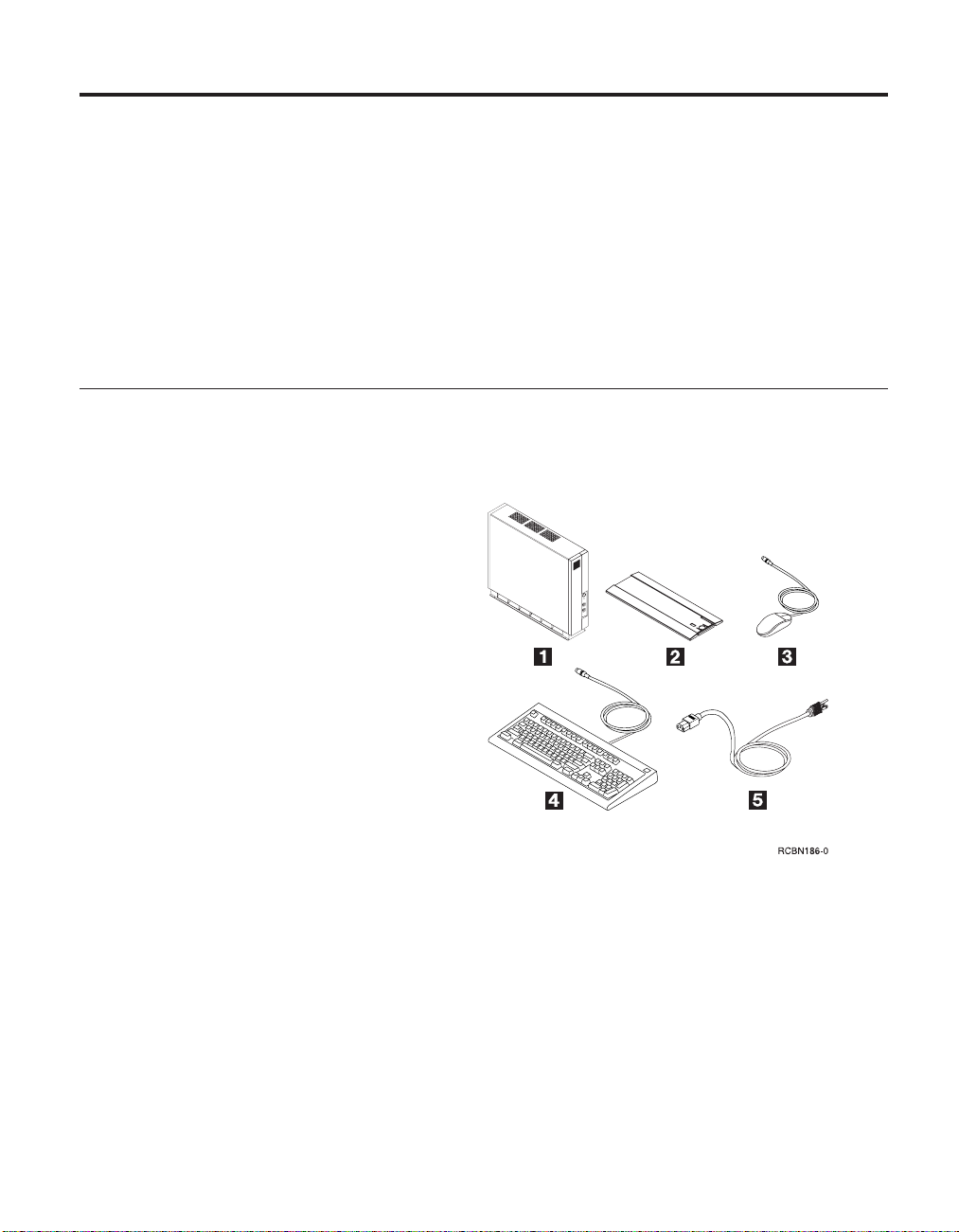
Standard hardware
Table 1. Standard Components
The Type 8364 Network Station ships with the following standard hardware
components:
«1¬ Network Station
«2¬ Base
«3¬ 2-button Mouse
«4¬ Keyboard
«5¬ Power cord
The standard Network Station hardware includes the following:
v 266 MMX Intel Pentium processor
v SDRAM DIMM memory (see “Memory upgrade options” on page 7)
v 4 MB SGRAM video memory
v Integrated Token-Ring or Ethernet communication
v 16 bit internal and external sound
v One connector for CompactFlash card
v Two USB ports
© Copyright IBM Corp. 1999 3
Page 16
v Two PCI adapters
v Two serial ports
v One parallel port.
v One monitor port.
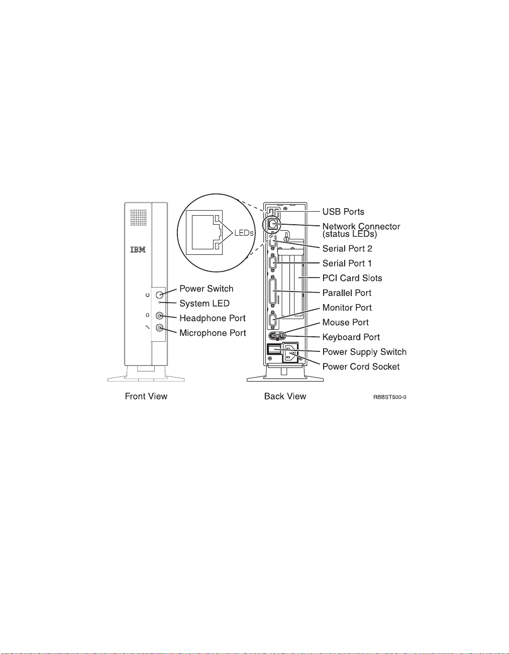
Hardware layout
Note: The Network Station connectors are standard connectors, and follow
the standard pin, signal, and signal direction configurations. See
“Appendix B. Connector pin information” on page 117 for details.
Figure 1. Type 8364 Network Station connectors
4 IBM Network Station
Page 17
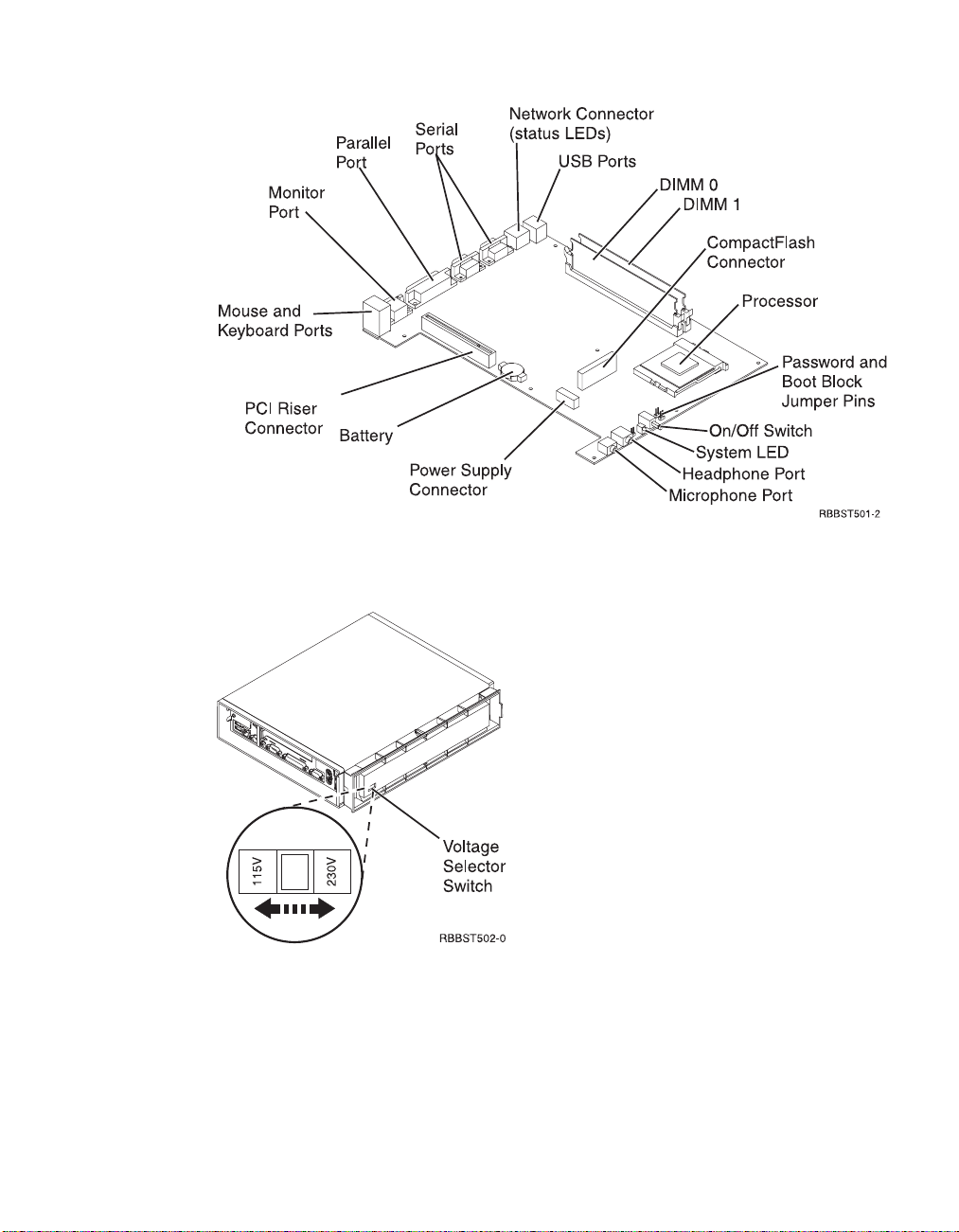
Figure 2. Type 8364 Network Station logic board
Figure 3. Type 8364 Network Station voltage selector switch (bottom view)
Note: All Network Stations are preset to the 230V setting when
manufactured.
Chapter 1. Learning about the IBM Network Station 5
Page 18

Communication hardware
Network Station hardware includes integrated Token-ring communication
(Models Txx), or integrated Ethernet communication (Models Exx). Both types
of communication can automatically determine line speed and duplex.
Required types of communication cable
The required type of cable for the Token-Ring model Network Station is
category 3 for 4MB ring speed operation. The required type of cable is
shielded twisted pair category 4 or 5 for 16MB ring speed operation.
The required type of cable for the Ethernet model for 10MB ring speed
operation is category 3 or higher Unshielded Twisted Pair (UTP). The required
type of cable for 100MB ring speed is category 5 UTP.
Refer to “Chapter 2. Replacing Network Station parts” on page 9 for IBM
communication cable options and part numbers.
Monitor specifications
A basic VGA-class monitor that meets the VESA standards of refresh rate and
resolution can function with the IBM Network Station. The IBM Network
Station supports VESA Display Power Management Signaling (DPMS) and
VESA Display Data Channel (DDC2B). Monitors attached to the IBM Network
Station do not require either standard.
It is important to remember that all resolutions and refresh rates may not be
supported by the monitor attached to the Network Station, or the operating
system kernel that the Network Station downloads from the network server.
See “Monitor specifications for the IBM Network Station Manager program”
on page 121 for resolution and refresh rate information that applies to
Network Station hardware that is configured for the IBM Network Station
Manager program.
See “Monitor specifications for WorkSpace On-Demand” on page 122 for
resolution and refresh rate information that applies to Network Station
hardware configured for WorkSpace On-Demand.
6 IBM Network Station
Page 19

Power consumption
Normal power consumption for the Network Station, while running
applications, ranges from 24 to 28 Watts. During periods of inactivity, the
system switches into the suspend state, and power consumption reduces to
approximately 18 Watts. Once the system enters the soft-off state, power
consumption reduces to approximately 10 Watts.
Note: Power consumption may fluctuate or vary from these values,
depending on the voltage selection (115V or 230V) of the Network
Station.
See “Power management” on page 34 for more information concerning power
management modes.
Power reduction occurs when you use the Network Station with a Video
Electronics Standards Association (VESA) Display Power Management
Signalling (DPMS) Standard monitor.
As an Energy Star Partner, IBM has determined that this product meets the
Energy Star Program guidelines for energy efficiency.
Upgrading hardware features
Customers can perform any of the following installation procedures:
v Installing PCI adapter cards.
v Installing a CompactFlash card.
v Connecting USB devices.
v Upgrading memory.
Refer to “Chapter 4. Performing hardware procedures” on page 17 for
installation instructions for these, and other hardware-related procedures.
Memory upgrade options
The Type 8364 Network Station has two random access memory (RAM) slots
that accept Synchronous Dynamic Random Access Memory (SDRAM) Dual
Inline Memory Modules, hereafter referred to as DIMMs. The Network Station
hardware supports memory expansions of 32, 64, and 128 MB.
The Network Station supports memory options up to 256MB. “Exchanging the
memory” on page 20 explains the procedure for installing and removing
Chapter 1. Learning about the IBM Network Station 7
Page 20

memory DIMMs in the Network Station. Refer to “Ordering optional features”
on page 16 for detailed memory specifications and optional Network Station
parts.
8 IBM Network Station
Page 21

Chapter 2. Replacing Network Station parts
This chapter defines the service strategy for the Network Station. For
information on ordering Network Station parts, refer to “Chapter 3. Ordering
Network Station parts” on page 11. “Chapter 4. Performing hardware
procedures” on page 17 provides the instructions that are needed to install
and remove parts, and perform other hardware-related procedures on the
Network Station.
Servicing the Network Station
All Network Station parts except the power supply are Customer Replaceable
Units (CRUs). The power supply is a part of the logic unit drawer assembly,
and should be replaced by the customer as an entire drawer CRU, if defective.
Country warranty service terms and conditions apply.
Note: The power supply part that can be exchanged or replaced is available
for onsite service from a service representative, or to be used as a
replacement part in a depot repair center.
Replacing the logic unit
To replace a Network Station logic unit, the customer must transfer features,
such as DIMMs and optional PCI adapter cards, to the replacement unit. IBM
delivers CRUs to the customer for exchange, and the customers return
defective part to IBM under the basic service offering. For upgrade service
offerings, a service representative delivers replacement parts, transfers features
and returns defective parts to IBM.
Customers must not remove the lithium battery when preparing a logic unit
for shipping. If customers do not transfer their features, the replacement units
will not operate properly. See “Handling static-sensitive devices” on page viii
for information about handling CRU parts.
Refer to “Chapter 4. Performing hardware procedures” on page 17 for
instructions on installing and removing Network Station parts. Refer to
“Ordering replacement parts” on page 11 to determine CRU part numbers for
replacement parts.
© Copyright IBM Corp. 1999 9
Page 22

Replacing all other parts
To replace a keyboard, mouse, power module, memory DIMM, or other
Network Station part, remove the part from the system, and install a
replacement part.
Note: You need to return some parts to IBM. Always check the replacement
part packaging for any return instructions regarding defective parts.
Returning parts to IBM
To return a defective logic unit to IBM, customers must ship only the logic
unit drawer (covers not included). The customer must package the defective
part by using the packaging container they received when the replacement
part arrived.
Note: Customers should not ship features, such as memory, and PCI adapter
cards, with the defective logic unit, because it is not possible for IBM to
return them.
If customers do not follow IBM shipping instructions, any damage to the
defective part may be charged to them. IBM covers shipping costs on all
warranted hardware and maintenance agreement hardware. Replacement
parts become the customer’s property in exchange for the defective parts,
which become the property of IBM.
10 IBM Network Station
Page 23

Chapter 3. Ordering Network Station parts
Ordering replacement parts
You can order IBM replacement parts for the Network Station. Contact IBM,
or your reseller, to order warranty parts and non-warranty parts. IBM will
provide warranty service without charge for parts during the warranty period
on an exchange basis only. If you need a replacement logic unit, IBM or your
reseller will give you instructions for returning your current logic unit to IBM.
The standard Network Station hardware shipped to the customer appears
below:
Table 2. Standard Components
Standard component list:
«1¬ Logic unit
«2¬ Cover assembly
«3¬ Base
«4¬ Power cord
«5¬ Mouse
«6¬ Keyboard
«7¬ Power supply
«8¬ Memory DIMM
«9¬ Lithium battery
The following tables list all Network Station parts that are supported by IBM
for this product. Use the reference number that is associated with each part
above to find the corresponding part numbers in the following tables.
© Copyright IBM Corp. 1999 11
Page 24

Table 3. Type 8364 Network Station replacement parts
Part
Reference Description Country
Logic unit and associated parts
«1¬ Logic Unit for Models Exx
(Ethernet Drawer)
«1¬ Logic Unit for Models Txx
(Token Ring Drawer)
«2¬ Network Station Cover
(Complete Cover Set)
«3¬ Base (Mounting Stand) All countries 41L4981
«9¬ Lithium Battery (3 Volt) All countries 33F8354
Note: This Network Station supports SDRAM DIMM memory that is 100MHz, 168
pin, 3.3 V, gold tab, unbuffered, and non-parity.
«8¬ Memory (32 MB SDRAM
DIMM)
«8¬ Memory (64 MB SDRAM
DIMM)
«8¬ Memory (128 MB SDRAM
DIMM)
All countries 41L5339
All countries 41L5392
All countries 41L4965
Memory
All countries 01K1146
All countries 01K1147
All countries 01K1148
number
12 IBM Network Station
Page 25
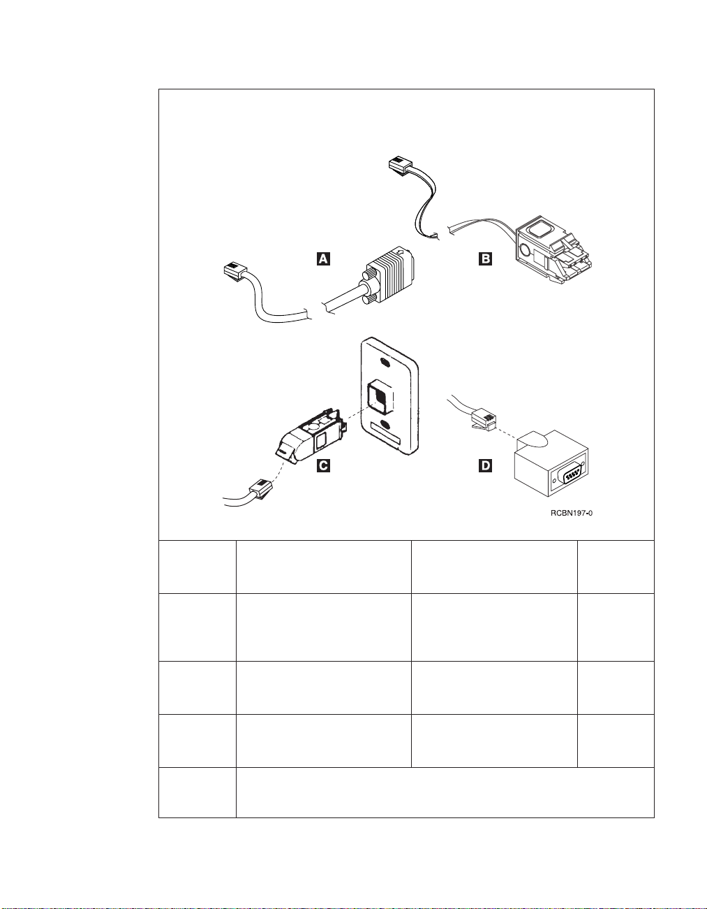
Table 3. Type 8364 Network Station replacement parts (continued)
Network cables
Note: The required cable type is category 3 for 4 MB ring speed operation. The
required cable type is shielded twisted pair category 4 or 5 for 16 MB ring-speed
operation.
«A¬ TTP RJ-45 plug STP cable for
connection to 9 pin D shell
connector
«B¬ TTP RJ-45 plug Shielded
Twisted Pair (STP) cable for
connection to IBM Cabling
System connector
«C¬ TTP RJ-45 socket adapter for
connection to IBM Cabling
System
«D¬ TTP RJ-45 socket adapter for
connection to 9 pin D shell
connector
Internal power supply
(see “Detachable power cables” on page 14 for part numbers)
All countries 60G1066
All countries 60G1063
All countries 73G8315
All countries 73G8320
Chapter 3. Ordering Network Station parts 13
Page 26

Table 3. Type 8364 Network Station replacement parts (continued)
«7¬ Power Supply (115V - 230V) All countries 94H1254
Mouse
«5¬ Mouse (two button) All countries 76H0889
Keyboards
«6¬ Keyboard Belgian UK 37L0857
«6¬ Keyboard Brazilian Portuguese 07L9450
«6¬ Keyboard Canadian French 37L0852
«6¬ Keyboard Danish 37L0860
«6¬ Keyboard Dutch 37L0861
«6¬ Keyboard French 37L0862
«6¬ Keyboard Finnish 37L0877
«6¬ Keyboard German 37L0863
«6¬ Keyboard Italian 37L0868
«6¬ Keyboard Latin America (Spanish) 37L0853
«6¬ Keyboard Norwegian 37L0869
«6¬ Keyboard Spanish 37L0876
«6¬ Keyboard Swedish 37L0877
«6¬ Keyboard Swiss (French and German) 37L0878
«6¬ Keyboard UK English 37L0881
«6¬ Keyboard US English ISO9995 37L0883
«6¬ Keyboard US English 37L0851
Detachable power cables
Table 4. Detachable power cables (10 Amp)
Plug Receptacle Country
14 IBM Network Station
Detachable power cables
Voltage
selection
Argentina, Australia, New Zealand 230V 13F9940
Part
number
Page 27

Table 4. Detachable power cables (10 Amp) (continued)
Abu Dhabi, Austria, Belgium, Bulgaria,
Botswana, Egypt, Finland, France,
Germany, Greece, Iceland, Indonesia,
Korea (South), Lebanon, Luxembourg,
Netherlands, Norway, Portugal, Saudi
Arabia, Spain, Sudan, Sweden, Turkey,
Yugoslavia
Bahamas, Barbados, Bolivia, Brazil,
Canada, Costa Rica, Dominican
Republic, El Salvador, Ecuador,
Guatemala, Guyana, Haiti, Honduras,
Jamaica, Japan, Netherlands Antilles,
Panama, Peru, Philippines, Taiwan,
Thailand, Trinidad, Tobago, U.S.A.
(except Chicago), Venezuela
Bahamas, Barbados, Bermuda, Bolivia,
Brazil, Canada, Cayman Islands,
Colombia, Costa Rica, Dominican
Republic, Ecuador, El Salvador,
Guatemala, Guyana, Haiti, Honduras,
Jamaica, Japan, Korea (South), Mexico,
Netherlands Antilles, Nicaragua,
Panama, Peru, Philippines, Puerto
Rico, Saudi Arabia, Suriname,
Trinidad, Taiwan, U.S.A
Bahrain, Bermuda, Brunei, Channel
Islands, Cyprus, Ghana, Hong Kong,
India, Iraq, Ireland, Jordan, Kenya,
Kuwait, Malawi, Malaysia, Nigeria,
Oman, Peoples’ Republic of China,
Qatar, Singapore, Tanzania, Uganda,
United Arab Emirates (Dubai), United
Kingdom, Zambia
Bangladesh, Burma, Pakistan, South
Africa, Sri Lanka
230V 13F9979
115V 1838574
115V 6952301
230V 14F0033
230V 14F0015
Denmark 230V 13F9997
Israel 230V 14F0087
Chapter 3. Ordering Network Station parts 15
Page 28

Table 4. Detachable power cables (10 Amp) (continued)
Ordering optional features
You can order optional features for the Network Station. See “Compatible
CompactFlash cards” on page ix for information about ordering optional
CompactFlash cards. Contact IBM, or your reseller, to order options such as
memory DIMMs and network cables.
Chile, Ethiopia, Italy 230V 14F0069
Liechtenstein, Switzerland 230V 14F0051
16 IBM Network Station
Page 29

Chapter 4. Performing hardware procedures
This chapter includes the procedures for exchanging parts in the Network
Station logic unit, clearing CMOS, reading the boot block, and writing the
boot block.
There are two configuration utilities you can use to configure your Network
Station hardware for the network server. Each setup utility interacts with the
Network Station hardware to report configuration errors and hardware
problems differently:
v See “Chapter 11. Identifying problems with hardware that is configured for
NS Boot” on page 69 to determine whether or not it is necessary to replace
the Network Station logic unit, or any other parts, when working with the
NS Boot utility.
v See “Chapter 13. Identifying problems with hardware that is configured for
BIOS” on page 93 to determine whether or not it is necessary to replace the
Network Station logic unit, or any other parts, when working with the basic
input and output system (BIOS) setup utility.
For information on ordering Network Station parts, refer to “Chapter 3.
Ordering Network Station parts” on page 11.
The hardware-related procedures in this chapter have been separated into two
sections:
v “Installing and removing parts” on page 18:
– “Removing the logic unit to install parts” on page 18.
– “Installing an optional CompactFlash card” on page 19.
– “Exchanging the lithium battery” on page 20.
– “Selecting the voltage for your location” on page 21.
– “Exchanging the memory” on page 20.
– “Installing an optional PCI card” on page 19.
– “Replacing the power supply” on page 22.
v “Clearing the administrator password and CMOS, creating a recovery
CompactFlash card, and reading a CompactFlash card” on page 24
– “Clearing CMOS” on page 24.
– “Creating a recovery CompactFlash card” on page 25.
– “Reading a compact flash card” on page 26.
© Copyright IBM Corp. 1999 17
Page 30
It is important that you understand all of the information that is presented in
“Safety notices” on page vii before performing any hardware-related
procedures on Network Station hardware.
Installing and removing parts
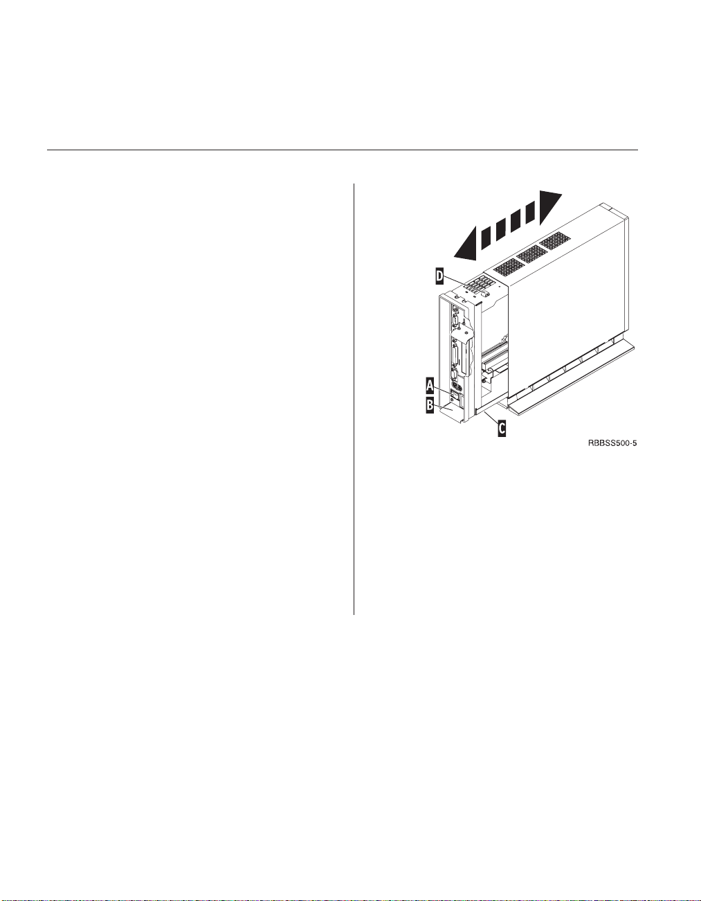
Removing the logic unit to install parts
Read Safety notices, and “Handling static-sensitive
devices” on page viii before continuing.
1. Turn off the power supply switch «A¬.
2. Disconnect all cables from the Network Station.
3. Hold the Network Station cover assembly, lift
latch «B¬, and pull the logic unit «C¬ out.
4. Carefully lay the logic unit down with the
internal components facing up. You are now
ready to perform the installation procedures
provided in this chapter.
Attention: Do not set the logic unit down on the
white power switch.
5. Complete the procedure, “Reassembling the
Network Station” when you are finished
installing components in the logic unit.
Reassembling the Network Station
Read Safety notices, and “Handling static-sensitive
devices” on page viii before continuing.
1. To reassemble the Network Station, carefully slide
the logic unit «C¬ into the cover assembly while
depressing the slide stop «D¬.
2. Slide the logic unit completely into the cover
assembly, until the latch «B¬ is engaged.
18 IBM Network Station
Page 31
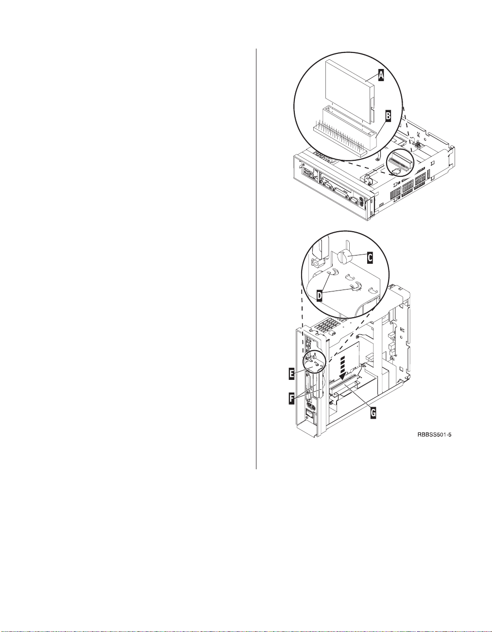
Installing an optional CompactFlash card
Read “Caution notices” on page viii, “Removing the
logic unit to install parts” on page 18 and
“Compatible CompactFlash cards” on page ix before
continuing.
1. Match the grooves on the sides of the
CompactFlash card «A¬ to the inside of the
connector «B¬.
2. Install the CompactFlash card «A¬ into the
connector «B¬.
Note: Do not force the card into the connector, as
it will damage both the Network Station, and the
CompactFlash card.
3. See “Reassembling the Network Station” on
page 18.
Installing an optional PCI card
Complete the procedure, “Removing the logic unit to
install parts” on page 18 before performing the
following Peripheral Component Interconnect (PCI)
procedure.
1. Loosen the thumb screw «C¬ to slide the plate «E¬
up.
2. Remove the PCI slot covers «F¬.
3. From inside the logic unit, install the PCI card
down into both the slot, and the PCI socket «G¬.
Note: Inserting the first PCI card into the socket
closest to the logic board makes installing a
second PCI card easier.
4. Install PCI slot covers over any empty slots.
5. Slide the plate «E¬ down until the tabs «D¬ secure
the PCI slot covers «F¬ firmly into place.
6. Tighten the thumb screw «C¬,
7. See “Reassembling the Network Station” on
page 18.
Chapter 4. Performing hardware procedures 19
Page 32

Exchanging the memory
Complete the procedure, “Removing the logic unit to
install parts” on page 18 before performing the
following Dual Inline Memory Module (DIMM)
procedures.
1. To remove a DIMM from the logic unit, press the
two tabs «B¬ located at each end of the DIMM
«A¬ out and down.
2. To install a DIMM into the logic unit, align the
notches on the bottom of the DIMM «A¬ with the
notched areas on the memory socket.
3. Press down firmly on the center of DIMM «A¬
until the memory socket tabs «B¬ flip up.
4. See “Reassembling the Network Station” on
page 18.
Exchanging the lithium battery
Read “Caution notices” on page viii, and see
“Removing the logic unit to install parts” on page 18
before continuing.
1. To remove the battery, place your thumb on the
battery «C¬ and lift it up with your index finger.
2. Dispose of the used battery according to your
local regulations.
3. Install the new battery into the battery socket «D¬,
with the ″+″ sign facing up.
4. See “Reassembling the Network Station” on
page 18.
Note: If you receive an error message on your screen
after performing this procedure, See “Chapter 11.
Identifying problems with hardware that is
configured for NS Boot” on page 69, or “Chapter 13.
Identifying problems with hardware that is
configured for BIOS” on page 93.
See “Setting the date and time” on page 57, and
“Part 3. Configuring the Network Station” on page 37
to reconfigure the Network Station.
20 IBM Network Station
Page 33

Selecting the voltage for your location:
Note: All Network Stations are preset to the 230V
setting when manufactured.
1. Power off the Network Station.
2. Remove the base from the Network Station.
3. Locate the voltage selector switch «A¬.
4. Use a pen, or similar object, to slide the switch to
the correct setting for your location (see Voltage
selection in “Detachable power cables” on
page 14).
5. Slide the base back on to the Network Station.
6. Power on the Network Station.
Chapter 4. Performing hardware procedures 21
Page 34
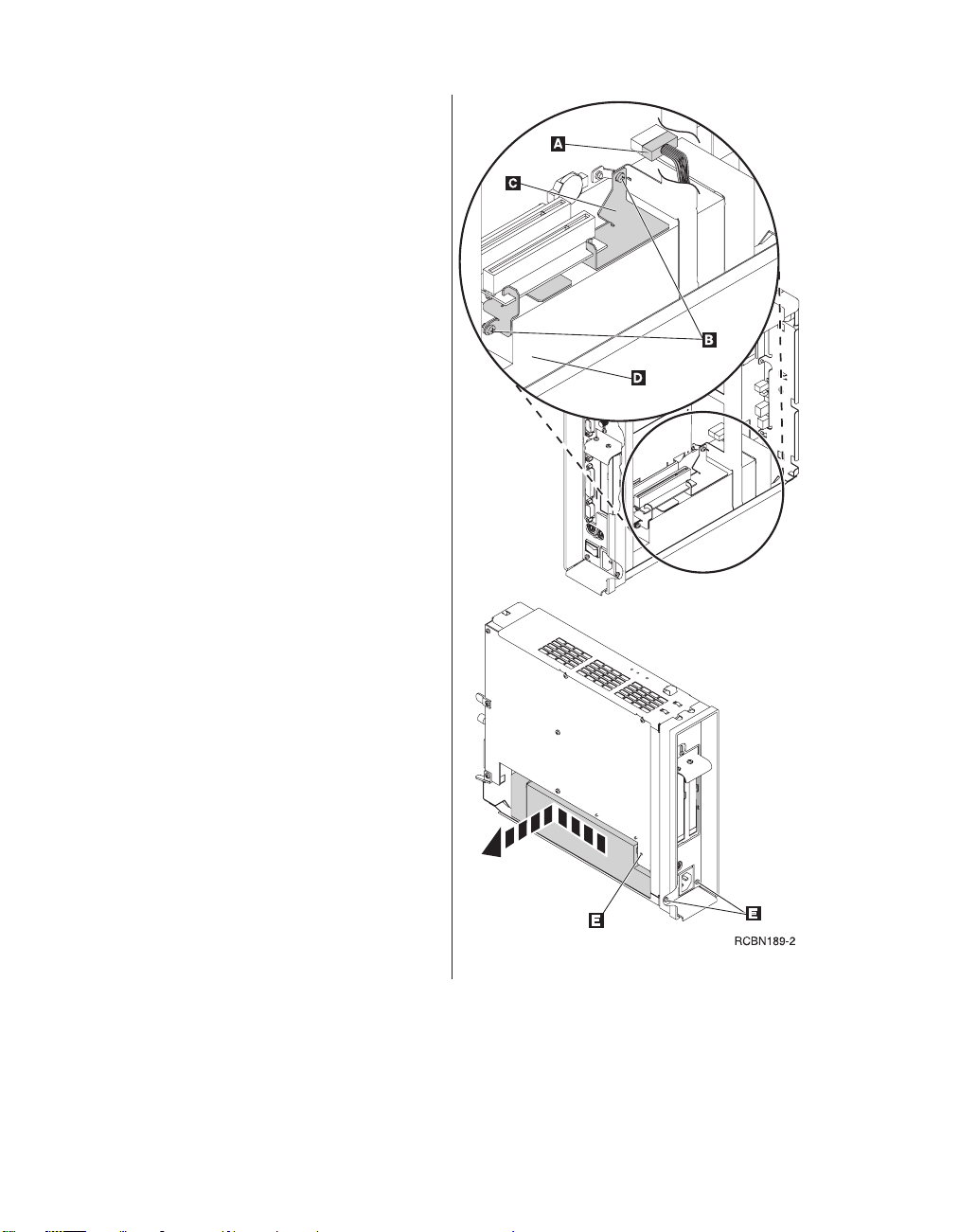
Removing the power supply:
Notes:
1. Only IBM-authorized personnel should
remove the power supply.
2. You will need a Phillips head screwdriver for
the following procedure.
1. Complete the procedure, “Removing the logic
unit to install parts” on page 18 before
continuing.
2. Disconnect the power supply connector «A¬
from the logic board.
Pinch the top of the power supply connector
as you disconnect it from the logic board.
This releases the power supply connector
latch.
3. Remove the two screws «B¬ attaching the
support plate «C¬ to the power supply «D¬.
4. Pull the support plate «C¬ out of the logic
unit and set it aside.
5. Remove the three screws «E¬ attaching the
power supply to the logic unit.
6. Push the power supply toward the front of
the logic unit until it stops.
7. Carefully remove the power supply from the
logic unit.
8. Continue with the procedure, “Installing the
power supply” on page 23.
22 IBM Network Station
Page 35

Installing the power supply:
1. Carefully install the power supply into the
logic unit so that the power supply fan
assembly faces the front of the logic unit.
2. Slide the power supply toward the back of
the logic unit until it stops.
3. Make sure that the power supply is seated
correctly, and firmly into the logic unit.
4. Secure the power supply with the three
Phillips head screws «A¬ removed during the
power supply removal procedure.
5. Slide the support plate «B¬ into place between
the riser card and power supply.
6. Secure the support plate with the two Phillips
head screws «C¬ removed during the power
supply removal procedure.
7. Install the power connector «D¬ into its socket
on the logic board.
8. See “Reassembling the Network Station” on
page 18.
Chapter 4. Performing hardware procedures 23
Page 36

Clearing the administrator password and CMOS, creating a recovery CompactFlash card, and reading a CompactFlash card
Clearing the administrator password, and
CMOS
Network Stations configured for WSOD: This
procedure clears all configuration settings on
Network Stations that have been configured from
the BIOS setup utility for the WorkSpace
On-Demand operating system (hereafter referred
to as WSOD). Refer to “Chapter 7. Selecting a
setup utility” on page 39 when you have
completed this procedure.
Network Stations configured for NS Boot: This
procedure only clears the administrator
password. This procedure does not not load
factory default settings. If you want to load the
factory default settings on a Network Station that
has been configured from the NS Boot utility,
perform the procedure “Loading the factory
defaults” on page 50.
1. Perform the procedure, “Removing the logic
unit to install parts” on page 18 before
continuing.
2. Move the jumpers into configuration «2¬.
Note: All systems ship with jumpers installed
in configuration «1¬.
3. Power on the Network Station and wait a few
moments.
This requires you to reconnect the power
cable to the logic unit. The system LED
flashes green at this time, on Network
Stations that are configured for WSOD. There
are no system LED indications at this time,
on Network Stations that are configured for
NS Boot.
4. Power off the system.
5. Move the jumpers back into the default
configuration «1¬.
If you do not move the jumpers back into
configuration «1¬, your Network Station may
not function properly.
6. See “Reassembling the Network Station” on
page 18.
24 IBM Network Station
Page 37

Creating a recovery CompactFlash card:
This procedure creates a copy of the Network
Station firmware (hereafter referred to as flash
image). The flash image that is stored on the
CompactFlash card includes both NS Boot and
BIOS images. You need a CompactFlash card to
complete this procedure (see “Compatible
CompactFlash cards” on page ix).
Note: Once you create a recovery CompactFlash
card for a series 2800 (machine type 8364)
Network Station, it can only be used to re-flash a
series 2800 Network Station.
1. Complete the procedure, “Removing the logic
unit to install parts” on page 18 before
continuing.
2. Insert the CompactFlash card into the
connector (see “Installing an optional
CompactFlash card” on page 19).
3. Move the jumpers into configuration «2¬.
Note: All systems ship with jumpers installed
in configuration «1¬.
4. Power on the Network Station.
This requires you to reconnect the power
cable to the logic unit.
5. Wait for the system LED to flash green.
Note: If the system LED flashes amber, the
image was not created. Repeat the procedure,
or see “Indicators of Network Station
problems” on page 73 for problem
determination.
6. Power off the Network Station.
7. Remove the CompactFlash card and store in a
safe place.
8. Move the jumpers back into the default
configuration «1¬.
If you do not move the jumpers back into
configuration «1¬, your Network Station may
not function properly.
9. See “Reassembling the Network Station” on
page 18.
Chapter 4. Performing hardware procedures 25
Page 38

Recovering the flash image
This procedure explains how to recover the flash
image of a Network Station by reading from a
recovery CompactFlash card. You need a
CompactFlash card with a series 2800 (machine
type 8364) flash image to complete this
procedure. See “Creating a recovery
CompactFlash card” on page 25 to create a
recovery CompactFlash card.
1. Complete the procedure, “Removing the logic
unit to install parts” on page 18 before
continuing.
2. Insert the CompactFlash card into the
CompactFlash connector (see “Installing an
optional CompactFlash card” on page 19).
3. Move the jumpers into configuration «2¬.
Note: All systems ship with jumpers installed
in configuration «1¬.
4. Power on the Network Station.
This requires you to reconnect the power
cable to the logic unit.
5. When the flash image has been re-flashed, the
LED will flash green.
If the system LED is amber, or flashes amber,
the flash image cannot be re-flashed. Try a
different CompactFlash card with the series
2800 (machine type 8364) flash image stored
on it, or recreate the recovery CompactFlash
card (see “Creating a recovery CompactFlash
card” on page 25) and then repeat this
procedure. If you are still unable to recover
the flash image, replace the logic unit (see
“Replacing the logic unit” on page 9).
6. Power off the system.
7. Remove the CompactFlash card from the
connector.
8. Move the jumpers back into the default
configuration «1¬.
If you do not move jumpers back into
configuration «1¬, your Network Station may
not function properly.
9. See “Reassembling the Network Station” on
page 18.
26 IBM Network Station
Page 39

Part 2. Software Overview
Chapter 5. IBM Network Station Manager
software features for Network Station ..29
Overview .............29
Chapter 6. Work Space On-Demand
software features for Network Station ..31
Overview .............31
Boot protocols ...........32
RPL..............32
DHCP and PXE ..........32
Java virtual machine .........32
IBM server login ..........33
Webbrowser............33
Printer management .........33
Application management........33
WakeonLAN...........34
Power management .........34
System-low-power states .......35
Monitor low-power states ......35
© Copyright IBM Corp. 1999 27
Page 40

28 IBM Network Station
Page 41

Chapter 5. IBM Network Station Manager software features for Network Station
Overview
The IBM Network Station Manager program is a browser-based application.
You can configure the Network Station for the IBM Network Station Manager
program from the NS Boot utility (see “Chapter 8. Configuring the Network
Station from the NS Boot utility” on page 43). The IBM Network Station
Manager program can be used to perform the following tasks:
v To construct the launch bar for the Network Station desktop:
You can configure the types and number of folders and applications with
the Desktop—>Launch Bar function of the application.
v To configure settings for:
– The System - All IBM Network Station thin clients or all Network Station
users.
– A Group - A group of Network Station users.
– A User - A specific Network Station user.
– A Workstation - A specific Network Station.
v To configure or customize specific setup tasks:
– Hardware, such as workstations and printers.
– Applications, such as 5250 sessions, Netscape Communicator, or locally
or remotely configured programs.
– Desktop look and content, such as font size, icon placement, and desktop
background.
– Environment and Administration, such as network settings such as
proxies, as well as language settings for messages and menus.
Refer to Using IBM Network Station Manager SC41-0690 for more information
about IBM Network Station Manager. For the most recent version of this
information, go to the following website:
http://www.ibm.com/nc/pubs
© Copyright IBM Corp. 1999 29
Page 42

30 IBM Network Station
Page 43

Chapter 6. Work Space On-Demand software features for Network Station
This chapter describes the software and licensed internal code features that
are associated with the Network Station. The licensed internal code features
discussed in this chapter have been configured in the Network Station setup
utility.
The Network Station setup utility is the system administrator’s tool for
configuring the basic input and output system (BIOS). The system
administrator can use the setup utility to set the system date and time, change
default power management settings, and much more. The system
administrator can also use the setup utility to obtain information about the
system, and its installed features. See “Chapter 12. Startup sequence of
Network Stations configured for WorkSpace On-Demand” on page 91 for
information on configuring Network Station power management features,
boot protocols, security features, and more.
The WorkSpace On-Demand server administrator controls the software that is
downloaded in the client image. Use this book in conjunction with the
WorkSpace On-Demand Administrator’s Guide shipped with the server software.
Overview
WorkSpace On-Demand is an operating system that utilizes thin clients that
are designed to be remotely loaded from a network server. The WorkSpace
On-Demand client runs Java applications, a browser, and the Personal
Communications Entry Level host access application. It also supports running
DOS, Windows 3.1, and IBM Operating System 2 (IBM Operating System/2
(OS/2)) stand-alone applications.
WorkSpace On-Demand runs on an OS/2 Warp Server and provides enhanced
server support and administrator functions to manage the Network Station.
The WorkSpace On-Demand server downloads this software across the local
area network (LAN) when you power on the Network Station. The client
provides user logon capability and a simplified desktop with program objects,
or icons, to run client applications.
For more information concerning WorkSpace On-Demand, refer to the
WorkSpace On-Demand Administrator’s Guide, shipped with the server software.
© Copyright IBM Corp. 1999 31
Page 44

Boot protocols
RPL
DHCP and PXE
The Network Station has the following boot protocol options:
v Remote Program Load (RPL)
v Dynamic Host Configuration Protocol (DHCP) and Preboot Execution
Protocol (PXE)
Note: The Network Station’s boot protocol’s default configuration is RPL.
You can select the Network Station’s boot protocol settings by entering the
setup utility. For more information, refer to “Devices and I/O ports” on
page 55.
Remote Program Load (RPL) is an IEEE (Institute of Electrical and Electronics
Engineers) 802.2 LLC (logical link control) level boot protocol. The Network
Station firmware (hereafter referred to as flash image) initializes the network
adapter and broadcasts its network address over the network for a server
connection.
Dynamic host configuration protocol (DHCP) and Intel’s Preboot Execution
Environment (PXE) are boot mechanisms which take advantage of
Transmission Control Protocol/Internet Protocol (TCP/IP) networks. The boot
protocol code initializes the network adapter within the system.
Java virtual machine
The Java Virtual Machine (VM) for WorkSpace On-Demand is part of the
licensed program. Java VM performs like a software version of a Central
Processing Unit (CPU). This program interprets Java instructions and runs
them on the hardware.
The Java VM runs compiled Java code, stand-alone Java applications, and
downloaded applets for Web browsers. The Java VM provides additional tools
for overcoming programming obstacles in the Java language that allow
customers to create their own languages. Customer programs are accessible
from any Java application, in any Java interpreter, on nearly any computer.
The Java Virtual Machine:
v Resolves run-time dynamic links to Java packages. The packages also store
as .class files
32 IBM Network Station
Page 45

v Runs byte-code operands in .class files.
v Creates instances of classes at runtime.
v Calls methods and accessing attributes within classes.
v Handles calls to Java packages and classes.
v Handles calls to stand-alone methods that are considered part of the Java
Refer to the WorkSpace On-Demand Administrator’s Guide, shipped with the
server software, for more information on Java VM and its functions.
IBM server login
The Network Station’s login window appears after the operating system has
fully loaded. The client desktop will display after the server has authenticated
the user’s identification and password. The user’s identification determines
the applications which will be available on the client desktop. Refer to the
WorkSpace On-Demand Administrator’s Guide to configure user profiles on the
server.
Web browser
The Network Station supports a Web browser. Refer to the information that
shipped with the server software for information about adding applications
such as the Web browser to users’ profiles.
library, but are not carried out directly in Java code.
Printer management
The customer may configure network printers and Network Station-attached
printers from the server software. The customer has access to all properly
configured network printers from all Network Stations. The customer may
configure network printers and Network Station attached printers from the
server. However, some software applications are not compatible with all
configured printers. Refer to the information that shipped with the server
software for details on how to configure printers and software applications.
Application management
The network administrator may change an application on behalf of all users.
For example, the administrator may want to configure the Web browser for all
users. Administrator passwords prevent users from changing application
configurations.
Chapter 6. Work Space On-Demand software features for Network Station 33
Page 46

For more information about application management, refer to the information
that shipped with the server software.
Wake on LAN
The Wake on LAN feature of the Network Station allows remote server access
of the client during power-managed states. Wake on LAN is useful for
administrating Network Stations during non-peak hours of operation.
Remote access from a LAN server allows a Network Station to perform
system management routines, transfer files, track inventory, assets, and
perform other tasks.
Servers with Wake on LAN technology can send wake-up frames over the
network to a Wake on LAN-enabled Network Station. The Network Station
will wake from its low power states when it receives one of these frames.
You can enable or disable the Network Station’s Wake on LAN feature by
entering the setup utility. For more information, refer to the BIOS screen
summary for “Power management” on page 62.
Power management
The Network Station has many built in features that lower the total cost of
ownership. One of these features is the system’s ability to automatically enter
power-managed states. The administrator can manage the system at the server
when the system is in these states. This allows for total management of the
system when the system is not in use, and is in a low power state. See
“System-low-power states” on page 35, and “Monitor low-power states” on
page 35 for detailed information on the Network Station’s power managed
states.
Power management is a feature of the Network Station basic input and output
system (BIOS). When the Network Station recognizes a period of inactivity,
this power management feature reduces the system’s power consumption (see
“Power consumption” on page 7 for details). The Network Station’s local area
network (LAN) connection remains active regardless of the power
management state it is in.
The power management mode supported by the Network Station is the
Automatic Hardware Power Managed (AHPM) mode. Features of the AHPM
mode include the black-out of the screen while the system is not in use.
34 IBM Network Station
Page 47

The system will enter this power management mode within the default setting
of 30 minutes. You can set both the system and the system monitor to enter
the power-managed mode automatically. Refer to “Power management” on
page 62 for more information.
System-low-power states
The power management feature of the Network Station provides three
low-power states for the system: suspend, soft-off, and power-off. The system
enters these states after the delay time has elapsed. Refer to “Power
management” on page 62 for information concerning the configuration of the
system’s power management feature.
v Suspend: After a period of inactivity, the system enters the standby state.
When a key is pressed or the mouse is moved, the monitor resumes normal
operation and restores the screen image. See “Power management” on
page 34 for more details.
v Soft-off: This state occurs if the period of inactivity continues in the
suspend state. You cannot resume an application after exiting the system
soft-off state. The system will restart, and re-establish communications with
the server. This is a configurable setting in the BIOS setup utility, and the
default value is for the system to remain on. The system will not
automatically enter this power-managed state if the default setting is intact.
The monitor screen remains blank, and the monitor’s power indicator light
is similar to the standby state. The System LED will not operate in soft-off.
This is an indication of the system’s power state. To exit soft-off, press the
white power button.
v Power-off state: This state only occurs by setting the power supply switch
that is located at the back of the Network Station. This severs the system’s
network connection. The power supply switch must be on in order to exit
this power state.
The default settings for the Network Station’s delay times are 30 minutes for
the suspend state, and 1 hour for the monitor power-off state. Refer to “Power
management” on page 34 for information regarding Network Station default
settings.
Monitor low-power states
The power management feature of the Network Station provides three
low-power states for the monitor: standby, suspend, and power-off. The
monitor switches to the defined state after the delay time has elapsed. After
this time has elapsed, the Network Station will switch to one of the three
low-power states.
Chapter 6. Work Space On-Demand software features for Network Station 35
Page 48

The following paragraphs describe how an IBM monitor that complies with
the VESA DPMS standard responds to the Network Station’s power
management feature:
v Standby state: After a period of inactivity, the Network Station instructs the
monitor to enter the standby state. The Network Station clears the monitor
display and changes the appearance of the monitor’s power indicator light.
When a key is pressed or the mouse is moved, the monitor resumes normal
operation and restores the screen image.
v Suspend state: If the period of inactivity continues in the standby state, the
Network Station instructs the monitor to enter the suspend state. The
default setting for this state is 30 minutes. The monitor screen remains
blank, and the monitor’s power indicator light is similar to the standby
state. When a key is pressed or the mouse is moved, the monitor resumes
normal operation and restores the screen image.
v Power-off state: After a period of inactivity in the suspend state, the
Network Station instructs the monitor to enter the power-off state. The
default setting for this state is 1 hour. The Network Station keeps the
monitor screen blank and changes the appearance of the monitor’s power
indicator light. When a key is pressed or the mouse is moved, the monitor
resumes normal operation and restores the screen image after a short delay.
The default settings for the Network Station’s delay times are 30 minutes for
the suspend state, and 1 hour for the power-off state. Refer to “Chapter 9.
Configuring the Network Station from the BIOS setup utility” on page 51 for
information on the setup utility, and configuring the Network Station.
36 IBM Network Station
Page 49

Part 3. Configuring the Network Station
Chapter 7. Selecting a setup utility ...39
Selecting the NS Boot for Network Station
Manager configuration ........39
Selecting the BIOS for WorkSpace
On-Demand configuration .......40
The Automatic selection ........40
Changing firmware configurations ....41
Switching from the NS Boot for Network
Station Manager configuration .....41
Switching from the BIOS for WorkSpace
On-Demand configuration ......41
Chapter 8. Configuring the Network Station
from the NS Boot utility .......43
Identifying the NS Boot version .....43
Manually updating the NS Boot code . . . 43
Using the NS Boot utility .......45
IBM Network Station NS Boot tasks ....46
Changing the language setting of the NS
Boot utility ...........46
Selecting a keyboard language .....46
Setting the display resolution .....46
Configuring an IBM Network Station to
boot from Local (NVRAM) settings . . . 47
Displaying hardware information ....48
Displaying the boot log .......48
Enabling verbose diagnostic messages . . 49
Working with Service Aids ......49
Changing the local MAC address . . . 49
Changing the fast boot setting ....50
Changing the retry settings .....50
Changing the NS Boot themes setting 50
Loading the factory defaults ....50
Setting the date and time .....57
System security ..........58
Changing the administrator password 58
Advanced setup..........60
ISA legacy resources ........61
Power management ........62
Load default settings ........63
Chapter 9. Configuring the Network Station
from the BIOS setup utility ......51
Setup utility overview ........51
Entering the setup utility........51
Primary setup utility screens ......52
System summary .........53
Product data ...........54
Determining the BIOS revision level . . 54
Devices and I/O ports .......55
Start options ...........56
Dateandtime..........57
© Copyright IBM Corp. 1999 37
Page 50

38 IBM Network Station
Page 51

Chapter 7. Selecting a setup utility
You need to configure the Network Station hardware for the server that it will
be interfacing with on the network. Three configuration options appear on the
Change Firmware Support menu during the initial startup of the Network
Station hardware:
v BIOS for WorkSpace On Demand.
v NS Boot for Network Station Manager.
v Automatic selection.
The Change Firmware Support menu only appears during the initial startup
of the Network Station hardware, or after you have after you have reset the
Network Station firmware configuration (see “Changing firmware
configurations” on page 41).
The configuration option that you select determines the setup utility that you
will use to configure the Network Station. When you allow the Automatic
selection to be made, the Network Station hardware will attempt to
communicate across the network in order to distinguish which setup utility to
use. The BIOS and NS Boot setup utilities interact with the Network Station
hardware differently during the startup sequence, and when reporting
hardware problems and configuration errors.
v Refer to “Part 4. Resolving problems with hardware that is configured for
IBM Network Station Manager” on page 65 for problem resolution when
using the NS Boot for Network Station Manager configuration option.
v Refer to “Part 5. Resolving problems with hardware that is configured for
WorkSpace On-Demand” on page 89 for problem resolution when using the
BIOS for WorkSpace On Demand configuration option.
Selecting the NS Boot for Network Station Manager configuration
When you select the NS Boot for Network Station Manager option, the
Network Station becomes configured for IBM Network Station Manager. IBM
Network Station Manager is an operating system that can manage Network
Station hardware, when installed on a network server. The NS Boot utility
becomes the primary interface with the Network Station firmware once you
have NS Boot for Network Station Manager.
When you select the NS Boot for Network Station Manager option, you can
change the language setting of the utility. The NS Boot Main Menu displays
after you select a language setting.
© Copyright IBM Corp. 1999 39
Page 52

After you configure the Network Station and restart the system, it attempts to
communicate with the network server. See “Chapter 11. Identifying problems
with hardware that is configured for NS Boot” on page 69 for explanations of
any common problem indicators you experience, such as:
v System LED indications.
v Error codes and text messages.
v Audio beep sequences.
See “Changing firmware configurations” on page 41 to change your firmware
configuration option.
Selecting the BIOS for WorkSpace On-Demand configuration
When you select the BIOS for WorkSpace On Demand option, the Network
Station becomes configured for WorkSpace On-Demand. Work Space
On-Demand is an operating system that can manage Network Station
hardware, when installed on a network server. The BIOS setup utility becomes
the primary interface with the Network Station firmware once you have
selected BIOS for WorkSpace On Demand.
After the Network Station has completed the configuration process, it
attempts to communicate with the network server. See “Chapter 13.
Identifying problems with hardware that is configured for BIOS” on page 93
for explanations of any common problem indicators that you experience, such
as:
v System LED indications.
v Error codes and text messages.
v Audio beep sequences.
See “Changing firmware configurations” on page 41 to change your firmware
configuration option.
The Automatic selection
The Automatic selection allows the Network Station to attempt to configure
automatically, based on information that it has received from the network
server. If you do not make a selection from the Change Firmware Support
menu, the Network Station will default to the automatic selection. Once the
Network Station completes the automatic configuration, you can configure the
Network Station and restart the system. Refer to either “Chapter 11.
Identifying problems with hardware that is configured for NS Boot” on
page 69, or “Chapter 13. Identifying problems with hardware that is
configured for BIOS” on page 93, depending upon the configuration that your
40 IBM Network Station
Page 53

Network Station hardware performed, for explanations of any common
problem indicators the you experience, such as:
v System LED indications.
v Error codes and text messages.
v Audio beep sequences.
Changing firmware configurations
You may decide that you want to change your firmware configuration. The
following procedures explain how to change your firmware configuration
from within the firmware utilities.
Switching from the NS Boot for Network Station Manager configuration
To return to the Change Firmware Support menu after you have chosen the
NS Boot for Network Station Manager selection, perform the following
procedure:
1. Press Esc during the Network Station startup sequence.
2. Highlight Service aids and press Enter.
3. Highlight Change firmware support and press Enter.
4. Highlight the firmware option of your choice, and press Enter.
5. Press F10 to restart the Network Station.
Switching from the BIOS for WorkSpace On-Demand configuration
To return to the Change Firmware Support menu after you have chosen the
BIOS for WorkSpace On Demand selection, perform the following procedure:
1. Press F1 when the IBM Network Station logo displays.
2. When you see the prompt for the administrator password, enter IBMNCD.
3. Select the Start Options menu from the Configuration/Setup Utility menu
and press Enter.
4. Scroll down to the Firmware Selection field.
5. Using the left arrow keys and the right arrow keys, select the Other
Operating Systems option.
6. Press Esc to exit the Start Options menu.
7. Press Esc to exit the Configuration/Setup Utility menu.
8. Highlight the Yes, save and exit the Setup Utility option, and press Enter.
The Network Station automatically restarts.
Chapter 7. Selecting a setup utility 41
Page 54

42 IBM Network Station
Page 55

Chapter 8. Configuring the Network Station from the NS Boot utility
This chapter contains information about using the NS Boot utility of the IBM
Network Station thin client (hereafter referred to as the Network Station). The
NS Boot utility menu allows you to View or Set configuration settings for a
particular Network Station. The primary function of the NS Boot utility is to
communicate with network servers, and download the IBM Network Station
Manager program.
You can find and correct Network Station configuration issues that affect how
the Network Station accesses a network in the NS Boot utility. You can use the
IBM Network Station Manager program to restrict user privileges in the NS
Boot utility.
Identifying the NS Boot version
You can distinguish the NS Boot version of your Network Station the
following two ways:
v Look for the H20xxxxx (MM/DD/YY) version that is indicated during the
startup sequence of the Network Station. You may need to enable the
verbose diagnostic mode to see this display (see “Enabling verbose
diagnostic messages” on page 49).
v Enter the NS Boot utility by pressing Esc during the startup sequence, and
select the Display hardware information option from the NS Boot Main
Menu.
Update your Network Station to the latest NS Boot version by doing the
following:
To manually update the NS Boot version of Network Stations with NS
Boot version H2033190 (03/31/99), see “Appendix A. Updating the NS
Boot version H2033190 (03/31/99)” on page 111.
To manually update the NS Boot version of Network Stations that are at
any other NS Boot version, see “Manually updating the NS Boot code”.
Manually updating the NS Boot code
To use the IBM Network Station Manager program to update the NS Boot
version from the server, perform the following procedure:
© Copyright IBM Corp. 1999 43
Page 56

Note: This procedure does not apply to Network Stations that have NS Boot
version H2033190 (03/31/99). You must manually update Network
Stations that have NS Boot version H2033190 (03/31/99) before you
can perform the procedures in this chapter. See “Appendix A. Updating
the NS Boot version H2033190 (03/31/99)” on page 111.
1. Select Configure network settings from the NS Boot Main Menu, and
press Enter.
2. Set Local (NVRAM) to First in the Network priority field. You can
select a boot method priority (first, second, and third) for the Network
Station to follow during startup.
Note: You can only set one boot option to First at a time. Disable DHCP
and BOOTP if you do not want them prioritized.
3. Type the IBM Network Station IP Address in the appropriate field on
menu1of4.
4. Type the Gateway IP Address in the appropriate field on menu 1 of 4.
5. Type the Subnet mask in the appropriate field on menu 1 of 4.
6. Type at least one Boot file server IP address in the appropriate fields on
menu2of4.
7. Type the IP address of the boot file server in the appropriate field.
8. Cycle through the Boot file server directory and file name, until you
have selected the empty field.
9. Refer to the following table and type the correct path for your server
platform in the empty Boot file server directory and file name field:
For this
platform:
AS/400 /QIBM/ProdData/NetworkStationV2/x86/proms/bflash.2800
Windows NT /NetworkStationV2/prodbase/x86/proms/bflash.2800
RS/6000 /usr/NetworkStationV2/prodbase/x86/proms/bflash.2800
10. If you are not sure what protocol you have configured your server for,
11. Press F3 to save your changes.
12. Restart the Network Station to complete the manual NS Boot version
44 IBM Network Station
Type this path:
select TFTP as your primary Boot file server protocol.
update.
Page 57

Using the NS Boot utility
Note: This procedure does not apply to Network Stations that have NS Boot
version H2033190 (03/31/99). You must manually update Network
Stations that have NS Boot version H2033190 (03/31/99) before you
can perform the procedures in this chapter. See “Appendix A. Updating
the NS Boot version H2033190 (03/31/99)” on page 111.
Access the NS Boot utility by performing the following procedure:
1. Power on the Network Station.
2. Enter the NS Boot utility by pressing Esc during the startup sequence.
Note: If you have enabled the password control from the IBM Network
Station Manager program, you must enter the case-sensitive
administrator password. You can specify the administrator
password through the IBM Network Station Manager program in
the Setup Tasks menu, by clicking Hardware—>Miscellaneous
Settings.
A screen similar to the following appears:
MENU03 IBM Network Station
Change language setting
Change keyboard setting
Change display settings
Configure network settings
Change boot file server settings
Change workstation configuration server settings
Change authentication server settings
Display hardware information
Display boot log
Change verbose diagnostic setting
Service aids
Enter=Continue F10=Reboot IBM Network Station
NS Boot Main Menu
Use cursor keys to select task.
Notes:
1. If you have not set a password in the IBM Network Station Manager
program, users can access the configuration settings in the NS Boot utility.
2. If you have set a password, users without the password can only view the
NS Boot utility, but you cannot make any configuration changes.
Chapter 8. Configuring the Network Station from the NS Boot utility 45
Page 58

3. If you changed the administrator password by using IBM Network Station
Manager program, you need to restart the Network Station. This enables
the new administrator password at the system unit.
If you limit user access from the IBM Network Station Manager program,
users may not see the menu shown above. They may see a menu that only
displays boot log information and hardware information.
IBM Network Station NS Boot tasks
You can perform the following NS Boot tasks:
v “Changing the language setting of the NS Boot utility” on page 46.
v “Selecting a keyboard language” on page 46.
v “Setting the display resolution” on page 46.
v “Configuring an IBM Network Station to boot from Local (NVRAM)
settings” on page 47.
v “Displaying hardware information” on page 48.
v “Displaying the boot log” on page 48.
v “Enabling verbose diagnostic messages” on page 49.
v “Changing the local MAC address” on page 49.
v “Loading the factory defaults” on page 50.
Changing the language setting of the NS Boot utility
__ 1. Enter the NS Boot utility by powering on the Network Station and
__ 2. Select Change language setting.
__ 3. Press Enter.
__ 4. Select your language.
__ 5. Press Enter to save your changes, and exit the menu.
Selecting a keyboard language
__ 1. Enter the NS Boot utility by powering on the Network Station and
__ 2. Select Change keyboard setting, and press Enter.
__ 3. Select your keyboard language.
__ 4. Press Enter to save your changes, and exit the menu.
Setting the display resolution
You can select a different display resolution for the operating system. In some
instances, this can improve the display quality of the monitor. See “Monitor
46 IBM Network Station
pressing Esc during the startup sequence.
pressing Esc during the startup sequence.
Page 59

specifications for the IBM Network Station Manager program” on page 121 for
more information on resolution options.
Notes:
1. Selecting a resolution that is not supported by your monitor can
permanently damage the monitor.
2. For the best video image, power on the monitor before you start the logic
unit.
__ 1. Enter the NS Boot utility by powering on the Network Station and
pressing Esc during the startup sequence.
__ 2. Select Change display settings and press Enter.
__ 3. Select Color palette.
__ 4. Choose your setting.
__ 5. Select Resolution and frequency.
__ 6. Choose your setting.
__ 7. Press Enter to begin a screen test.
a. If the test screen displayed correctly, press Enter to save your
settings.
b. If the test screen did not display correctly, press F12 to restore the
previous settings.
Configuring an IBM Network Station to boot from Local (NVRAM) settings
__ 1. Enter the NS Boot utility by powering on the Network Station and
pressing Esc during the startup sequence.
__ 2. Select the Configure network settings menu and press Enter.
__ 3. Configure the following NS Boot utility fields correctly for a successful
NVRAM boot:
__ a. Set Local (NVRAM) to First in the Network priority field. You
can select a boot method priority (first, second, and third) for the
Network Station to follow during startup.
Note: You can only set one boot option to First at a time.
Disable DHCP and BOOTP if you do not want them
prioritized.
__ b. Type the IBM Network Station IP Address in the appropriate
field on menu 1 of 4.
__ c. Type the Gateway IP Address in the appropriate field on menu 1
of 4.
__ d. Type the Subnet mask in the appropriate field on menu 1 of 4.
__ e. Type at least one Boot file server IP address in the appropriate
fields on menu 2 of 4.
Chapter 8. Configuring the Network Station from the NS Boot utility 47
Page 60

__ f. Refer to the following table when selecting the correct Boot file
server directory and file name on menu 2 of 4:
For this
platform:
AS/400 /QIBM/ProdData/NetworkStationV2/x86/kernel.2800
Windows NT /NetworkStationV2/prodbase/x86/kernel.2800
RS/6000 /usr/NetworkStationV2/prodbase/x86/kernel.2800
Select this choice:
__ g. Verify your Boot file server protocol settings on menu 2 of 4,
and press Enter.
__ h. If your configuration server is not the boot server, enter the
Workstation configuration server IP address on menu 3 of 4,
and perform the following two steps:
__ 1) Verify the Workstation configuration server directory for
your configuration server on menu 3 of 4.
__ 2) Verify the Workstation configuration server protocol
settings on menu 3 of 4.
__ i. Press Enter to advance to menu 4.
__ j. If your authentication server is not the boot server, enter the
Authentication server IP address on menu 4.
__ k. Press F3 to save your Local (NVRAM) configurations, and return
to the NS Boot Main Menu.
Displaying hardware information
To display the hardware information for your Network Station, perform the
following procedure:
__ 1. Enter the NS Boot utility by powering on the Network Station and
__ 2. Select Display hardware information, and press Enter.
Displaying the boot log
The boot log is a collection of all information and error messages that are
generated by the NS Boot utility during the current Network Station startup
sequence. Displaying the boot log allows you to identify and resolve
configuration issues and network issues. To display the boot log, perform the
following procedure:
__ 1. Enter the NS Boot utility by powering on the Network Station and
__ 2. Select Display boot log, and press Enter.
48 IBM Network Station
pressing Esc during the startup sequence.
pressing Esc during the startup sequence.
You can page through the boot log by pressing Enter.
Page 61

Enabling verbose diagnostic messages
You can enable and disable the display of verbose diagnostic messages on
your Network Station display. The default setting is Disabled. When the
verbose diagnostic messages are disabled, an image representing the
communication between the Network Station and a server displays during the
Network Station startup sequence.
When you change the verbose diagnostic setting to Enabled, informational
and error messages display during the Network Station startup sequence.
Note: The verbose diagnostic messages save to the boot log, regardless of the
verbose diagnostic setting.
__ 1. Enter the NS Boot utility by powering on the Network Station and
pressing Esc during the startup sequence.
__ 2. Select Change verbose diagnostic setting, and press Enter.
__ 3. Enable the verbose diagnostic mode.
__ 4. Press Enter to save your changes, and exit the menu.
Working with Service Aids
You can perform the following procedures from the Service Aids menu:
v “Changing the local MAC address”.
v “Changing the fast boot setting” on page 50.
v “Changing the retry settings” on page 50.
v “Changing the NS Boot themes setting” on page 50.
v “Loading the factory defaults” on page 50.
Changing the local MAC address
You can configure this option from the Service Aids menu. To change the
local MAC address, perform the following procedure:
__ 1. Enter the NS Boot utility by powering on the Network Station and
pressing Esc during the startup sequence.
__ 2. Select Service aids, and press Enter.
__ 3. Select Change local MAC address, and press Enter.
__ 4. Under Enable local MAC address, select Enabled.
__ 5. Under Local MAC address, type the local MAC address in the form of
00:00:00:00:00:00, and press Enter.
Chapter 8. Configuring the Network Station from the NS Boot utility 49
Page 62

Changing the fast boot setting
You can configure this option from the Service Aids menu. To change the fast
boot setting, perform the following procedure:
__ 1. Enter the NS Boot utility by powering on the Network Station and
pressing Esc during the startup sequence.
__ 2. Select Service aids, and press Enter.
__ 3. Select Change the fast boot setting, and press Enter.
__ 4. Select Enabled or Disabled, and press Enter.
Changing the retry settings
You can configure this option from the Service Aids menu. To change the
retry settings, perform the following procedure:
__ 1. Enter the NS Boot utility by powering on the Network Station and
pressing Esc during the startup sequence.
__ 2. Select Service aids, and press Enter.
__ 3. Select Change retry settings, and press Enter.
__ 4. Configure the retry settings, and press Enter to save your changes.
Changing the NS Boot themes setting
You can configure this option from the Service Aids menu. To change the NS
Boot theme settings, perform the following procedure:
__ 1. Enter the NS Boot utility by powering on the Network Station and
pressing Esc during the startup sequence.
__ 2. Select Service aids, and press Enter.
__ 3. Select Change NS Boot theme settings, and press Enter.
__ 4. Select an NS Boot theme, and press Enter to save your changes.
Loading the factory defaults
__ 1. Enter the NS Boot utility by powering on the Network Station and
__ 2. Select Service aids.
__ 3. Press Enter.
__ 4. Select Load factory defaults, and press Enter.
50 IBM Network Station
pressing Esc during the startup sequence.
This restarts the Network Station.
Page 63

Chapter 9. Configuring the Network Station from the BIOS setup utility
The Network Station setup utility is the system administrator’s tool for
configuring the Basic Input and Output System (BIOS). The information in
this chapter includes the following:
v “Setup utility overview”.
v “Entering the setup utility”.
v “Primary setup utility screens” on page 52.
v “Determining the BIOS revision level” on page 54.
Setup utility overview
The administrator can use the setup utility to set the system date and time,
change default power management settings, and much more. You can also use
the setup utility to obtain information about the system, and its installed
features.
You can only access the setup utility with the administrator password. The
default password shipped with the system is IBMNCD. The administrator can
change this password in the Network Station setup utility. Refer to “Changing
the administrator password” on page 58 for the procedure.
Without the administrator password, it is only possible to see system
summary data and product data. You cannot change the system BIOS without
the administrator password.
When you make configuration changes to the system, you will see arrows on
the setup utility screens, indicating the locations of the changes.
Entering the setup utility
To set the system date and time, change default power management settings,
or perform other configuration procedures, you must perform the following
procedure:
1. Power up the Network Station.
2. Press the F1 key during the IBM Network Station’s logo display, and after
the keyboard LEDs flash.
© Copyright IBM Corp. 1999 51
Page 64
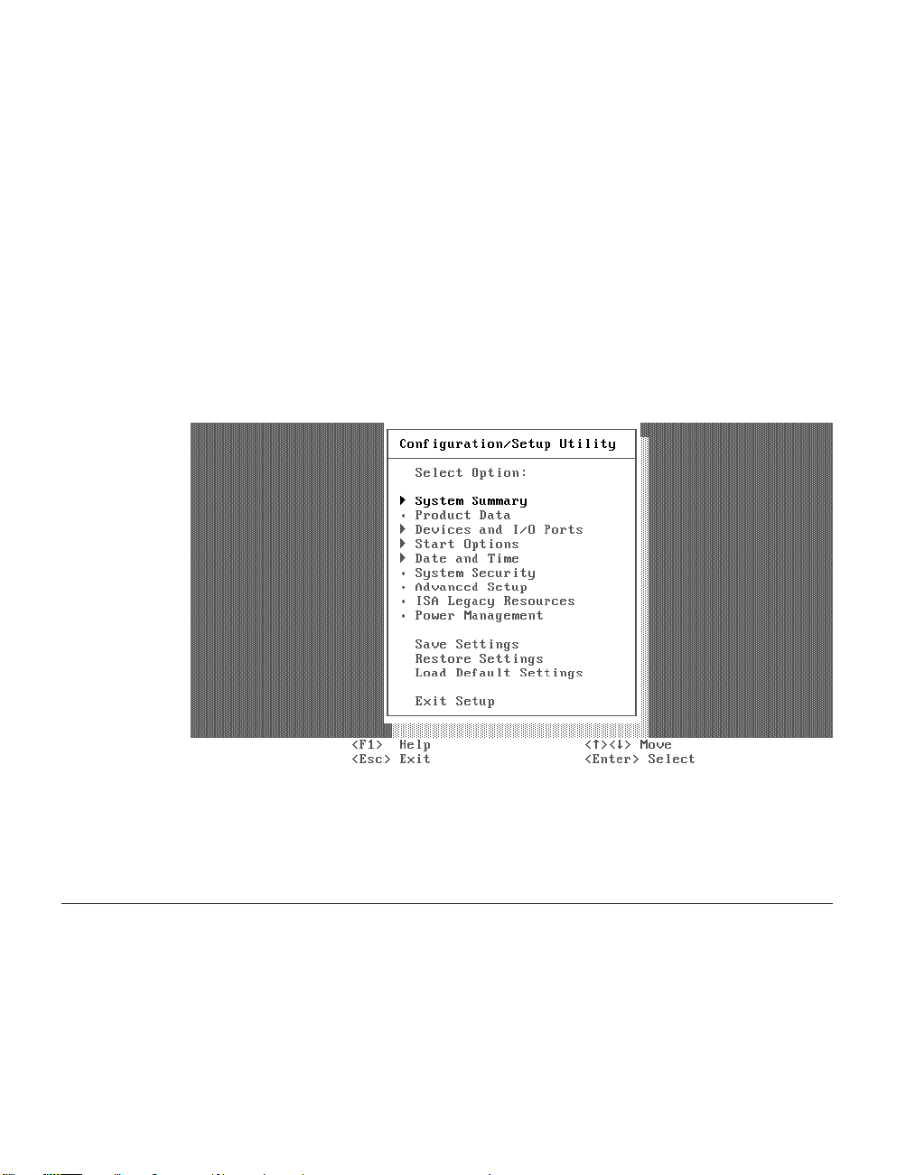
Note: Pressing F1 during the system’s keyboard test causes a false 301
Keyboard Error to display, and a prompt for the administrator
password to appear.
3. Type the administrator password.
Note: If you want to enter the setup utility and do not know the
password, perform the procedure, “Clearing the administrator
password and CMOS, creating a recovery CompactFlash card, and
reading a CompactFlash card” on page 24.
After the system has validated the administrator password, the main setup
utility screen will appear (see Figure 4 below). You can make changes to the
Network Station’s system defaults at this time.
Figure 4. Configuration/setup utility screen
To see the primary setup utility screens, and some basic configuration
procedures, refer to “Primary setup utility screens”.
Primary setup utility screens
Note: Setup screen references may be different depending on the Network
Station hardware, and date of manufacture.
52 IBM Network Station
Page 65

System summary
When you select the System Summary option from the Configuration/Setup Utility
menu, a screen similar to the following appears:
Chapter 9. Configuring the Network Station from the BIOS setup utility 53
Page 66
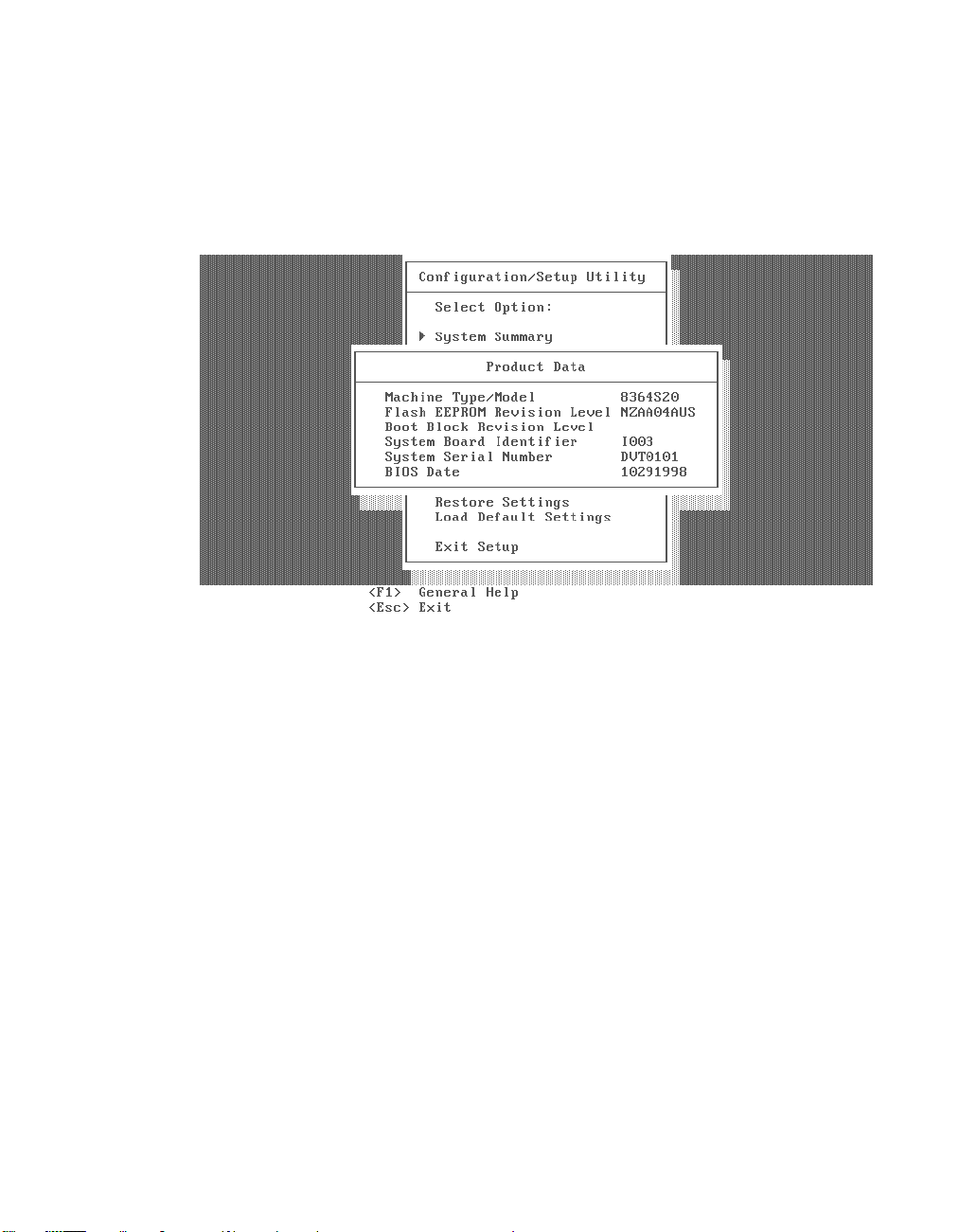
Product data
When selected, this screen displays the machine type, model number, serial number,
BIOS date, and BIOS revision level. The BIOS revision level indicates the read-only
memory (ROM) level of the Network Station, and the last two entries in the revision
level indicate the language. The boot block revision level and the system board
identifier indicate the level of the boot block and logic board, respectively.
Determining the BIOS revision level
It may be necessary for the system administrator to determine the current
BIOS level of Network Station hardware, when helping customers diagnose
Network Station problems. Refer to the following procedure to determine the
Network Station’s BIOS level:
1. Power up the system.
2. After the IBM logo appears on the monitor, and the keyboard LEDs have
flashed, press the F1 key to enter the setup utility.
Note: Pressing F1 during the system’s keyboard test causes a false 301
3. Type the administrator password to enter the setup utility.
Note: If you do not know the administrator password, press the ENTER
4. Once you have entered the setup utility, select the Product data menu.
5. The value listed in the Flash EEPROM revision-level field is the current
BIOS level.
54 IBM Network Station
Keyboard Error to display, and a prompt for the administrator
password to appear.
key.
Page 67

Devices and I/O ports
When selected, this screen allows the administrator to configure devices connected to
the Network Station. Network Station serial and parallel port addresses, IRQ levels,
setup, and support are accessible from this screen. The administrator is able to see the
types and sizes of devices installed on the system. The Network Station boot protocols,
message authentication code (MAC) address, and network setup are also accessible
from this screen.
Note: The Network Station’s boot protocol default configuration is RPL.
Chapter 9. Configuring the Network Station from the BIOS setup utility 55
Page 68

Start options
When selected, this screen allows the administrator to configure the Network Station
startup sequence. The Network Station will always start from the network first. The
″Primary Start-up Sequence″ is used when the system is powered on. The ″Start-up
Sequence″ is used when the system is powered on automatically through the
″Advanced Power Management″ menus. Enabling ″Power On Status″ displays the
diagnostic checkpoints during the power on self test (POST). Refer to “Diagnostic
checkpoints” on page 100 for a table of the diagnostic checkpoints.
56 IBM Network Station
Page 69

Date and time
When selected, this screen allows the administrator to view or change the system date
and time. See “Setting the date and time” for instructions.
Note: The operating system updates the Network Station system time, when the
system is booted from the Server. The operating system will not synchronize date with
the server.
Setting the date and time
You may need to change the date and time on the Network Station after
replacing the lithium battery (see “Exchanging the lithium battery” on
page 20). You can update the date and time through the Network Station
BIOS. Follow the procedure below to change the date and time on the
Network Station.
Setting the date and time:
1. Power up the system.
2. Press the F1 key during the IBM Network Station’s logo displays, and
after the keyboard LEDs have flashed.
Note: Pressing F1 during the system’s keyboard test causes a false 301
Keyboard Error to display, and a prompt for the administrator
password to appear.
3. Type the administrator password when prompted.
Note: If you do not know the current administrator password, refer to
“Clearing the administrator password and CMOS, creating a
Chapter 9. Configuring the Network Station from the BIOS setup utility 57
Page 70
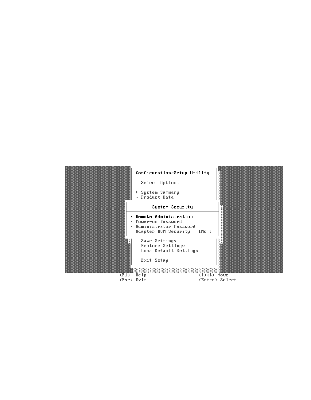
4. Press the Enter key.
5. Choose ″Date and Time″ from the main utility screen.
6. Enter the correct date and time in the space that is provided.
7. Exit the setup utility.
System security
When selected, this screen offers the administrator the options of remote
administration, power-on passwords, and changing the administrator password. The
default Network Station administrator password is IBMNCD. Refer to “Clearing the
administrator password and CMOS, creating a recovery CompactFlash card, and
reading a CompactFlash card” on page 24, and “Changing the administrator password”
for related procedures. There is also an option to enable ″Adapter ROM Security.″ This
disables the keyboard during adapter ROM initialization, and will not allow users to
enter adapter configuration tools.
recovery CompactFlash card, and reading a CompactFlash card” on
page 24 for the procedure to reset the administrator password to the
system default.
Changing the administrator password
Note: This procedure explains how to change the administrator password
58 IBM Network Station
from the system default, or other value, which the system administrator
has determined. Refer to “Clearing the administrator password and
CMOS, creating a recovery CompactFlash card, and reading a
CompactFlash card” on page 24 for information on returning the
administrator password’s value to the system default.
Page 71

The system administrator may choose to change the administrator password
on the Network Station for security reasons. Follow the procedure below to
change the administrator password.
1. Power on the system.
2. Press the F1 key during the IBM Network Station logo display, and after
the keyboard LEDs have flashed.
Note: Pressing F1 during the system’s keyboard test causes a false 301
Keyboard Error to display, and a prompt for the administrator
password to appear.
3. Type the current administrator password when prompted.
Note: If you do not know the current administrator password, refer to
“Clearing the administrator password and CMOS, creating a
recovery CompactFlash card, and reading a CompactFlash card” on
page 24 for the procedure to reset the administrator password to
the system default.
4. Press the Enter key.
5. Choose ″System Security″ from the main setup utility screen.
6. Choose ″Administrator Password″ from the ″System Security″ screen.
7. Enter the new administrator password in the space that is provided.
8. Enter the new administrator password a second time in the space that is
provided.
9. Choose ″Change Administrator Password″ from the ″Administrator
Password″ screen.
10. Exit the setup utility.
Chapter 9. Configuring the Network Station from the BIOS setup utility 59
Page 72

Advanced setup
Note: If these features are configured improperly, the Network Station system may not
work properly. See “Load default settings” on page 63 for information on correcting
configuration errors.
When selected, this screen allows the system administrator to perform more advanced
configuration tasks, such as enabling or disabling the cache, ROM shadowing, and PCI
control.
60 IBM Network Station
Page 73

ISA legacy resources
If selected, this screen will display the memory resource used by the system for planar
devices, and other resource information, including I/O Port Resources, DMA resources,
and interrupt resources used by the system for on board devices.
Note: If these features are configured improperly, the Network Station system may not
work properly. See “Load default settings” on page 63 for information on correcting
configuration errors.
Chapter 9. Configuring the Network Station from the BIOS setup utility 61
Page 74
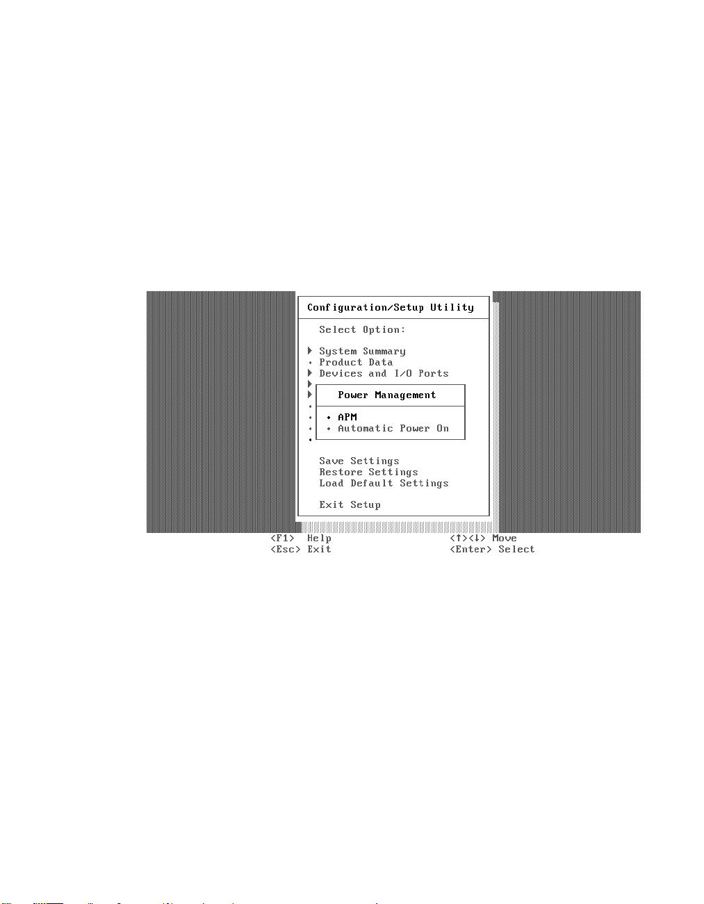
Power management
This screen allows the administrator to choose which power management features the
system will utilize. The administrator can disable power management or change
automatic power-on features. The administrator can also set the delay time the
Network Station will experience before the system will enter a low power state. See
“System-low-power states” on page 35, and “Monitor low-power states” on page 35, for
more information on the power management modes.
The administrator has the ability to choose what events can wake the system from a
low power state from this screen, as well. The administrator can enable or disable
Wake-On-LAN, modem ring, and set an alarm to wake the system, or enable and
disable PCI Wake events from this screen as well. See “Wake on LAN” on page 34, and
“Power management” on page 34 for related information.
62 IBM Network Station
Page 75
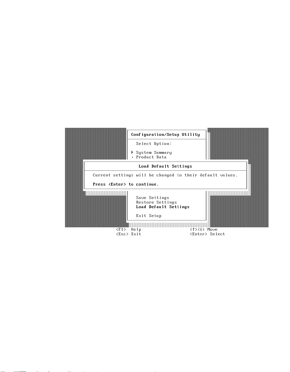
Load default settings
This option allows you to reset the setup utility configurations back to the system
default values. This is useful when trying to diagnose configuration errors (see
“Configuration errors” on page 105) in the system. Loading defaults will reset the
administrator password to the default value (IBMNCD), and will also reset all
customized settings to their default values. Refer to “Changing the administrator
password” on page 58 to reconfigure the administrator password.
Note:
v If you load defaults from the setup utility and then power off, you will see the
auto-configuration menu.
v If you load defaults from the setup utility and then save and exit, the Network
Station will reboot and come up in the setup utility; and if it boots, it will stay in the
setup utility after power off.
Chapter 9. Configuring the Network Station from the BIOS setup utility 63
Page 76

64 IBM Network Station
Page 77

Part 4. Resolving problems with hardware that is configured for IBM Network Station Manager
Chapter 10. Startup sequence of Network
Stations configured for the IBM Network
Station Manager program .......67
Chapter 11. Identifying problems with
hardware that is configured for NS Boot .69
Starting point for all problems ......69
Indicators of Network Station problems. . . 73
NS Boot audio beep sequences ......75
NS Boot error codes and text messages . . . 76
Group.............76
Subgroup ...........77
Message number .........78
Origin .............78
NS Boot error messages .......78
© Copyright IBM Corp. 1999 65
Page 78

66 IBM Network Station
Page 79

Chapter 10. Startup sequence of Network Stations configured for the IBM Network Station Manager program
This is the detailed startup sequence of events for Network Station hardware
that you have configured using the NS Boot utility. This startup sequence
assumes that you have already selected the NS Boot utility for the IBM
Network Station Manager operating system. If you have selected the BIOS for
WorkSpace On-Demand configuration option for your Network Station, refer
to the “Chapter 12. Startup sequence of Network Stations configured for
WorkSpace On-Demand” on page 91. If you have not selected the Network
Station firmware support yet, see “Chapter 7. Selecting a setup utility” on
page 39.
1. Power on all of the devices that are attached to the Network Station,
including the monitor, communication hubs, and printers.
2. Verify that the Network Station power cable is plugged into a working
properly grounded electrical outlet, the voltage switch that is located on
the bottom of the Network Station is set to the correct voltage for your
location (see “Selecting the voltage for your location” on page 21), and
that the power supply switch, located at the back of the Network Station,
is in the on position (1).
3. Press the white power switch on the front of the Network Station.
The system LED quickly flashes amber, and then remains steady green.
4. The installed Network Station system memory is detected and enabled.
5. The L1 cache is enabled and tested.
6. The L2 cache is enabled and tested.
7. The video initializes.
If you have already selected the NS Boot for Network Station Manager
option from the Change Firmware Support menu, skip to step 9 on
page 68. If you have not yet selected the Network Station firmware
support, continue with the following:
8. The Change Firmware Support menu displays on the screen.
Note: This step only occurs in the following situations:
v The initial startup of the Network Station hardware, after you
install the hardware for the first time.
v The initial startup of the Network Station hardware, after you
reset the firmware configuration.
The remaining steps in the Network Station startup sequence are true if you selectNS
Boot for Network Station Manager from the Change Firmware Support menu.
© Copyright IBM Corp. 1999 67
Page 80

If you have selected the BIOS for WorkSpace On Demand configuration option
for your Network Station, refer to the “Chapter 12. Startup sequence of Network
Stations configured for WorkSpace On-Demand” on page 91. See “Part 3.
Configuring the Network Station” on page 37 for the procedure to return to the
Change Firmware Support menu from the BIOS for WorkSpace On Demand
configuration option.
9. The IBM Network Station title, IBM copyright notice, and IBM logo
display on the screen.
10. The keyboard controller initializes, and the keyboard LEDs flash.
11. The NS Boot utility runs the network initialization code.
12. The Network Station contacts the server.
13. The operating system kernel initializes.
14. The IBM Network Station Manager Login screen displays.
68 IBM Network Station
Page 81

Chapter 11. Identifying problems with hardware that is configured for NS Boot
This chapter contains the procedures for identifying hardware problems that
can occur to Network Station hardware that you have configured from the NS
Boot utility. To learn more about selecting a setup utility for Network Station
hardware, refer to “Part 3. Configuring the Network Station” on page 37.
Continue with “Starting point for all problems” to identify Network Station
hardware problems.
Note: For the Network Station hardware to function properly when connected
to a network server, ensure that you have performed the following
tasks before continuing with the “Starting point for all problems”:
v Install and configure the appropriate server software on the network
server (go to http://www.ibm.com/nc for the latest installation
information).
v Configure the Network Station hardware for the network server
software (see “Part 3. Configuring the Network Station” on page 37).
You can obtain additional service support information on the World
Wide Web at the following URL:
http://www.ibm.com/nc
In the left frame, click Support.
Starting point for all problems
Network Station hardware reports hardware problems and configuration
errors when detected. The Network Station indicates problems in the
following ways:
v System LED indications.
v Audio beep sequences.
v Error codes and text messages.
LED indications and audio beep sequences generally occur before the IBM
Network Station logo displays. Error messages only appear on the monitor
after the IBM Network Station logo displays. It is important that you record
any system LED indications, audio beep sequences, error codes, or text
messages that occur when you experience a problem.
© Copyright IBM Corp. 1999 69
Page 82

Use the following procedures to identify any problems with Network Station
hardware that you are experiencing.
__ 1. Did you set the Network Station voltage selector switch that is located
on the bottom of the Network Station) to the correct voltage for your
location?
Note: All Network Station hardware ships with the voltage selector
switch preset to 230V.
Yes No
↓
v If you set the voltage selector switch to the 115V value in a
230V location, and power on the Network Station, the power
supply can be damaged, and may need to be replaced. The
power supply is a part of the complete logic unit assembly.
Customers should replace the logic unit when directed to
replace the power supply.
For on-site service technicians, there is an option to order
and replace the power supply only. See “Chapter 2. Replacing
Network Station parts” on page 9 to order a replacement
power supply, and then perform the procedure, “Replacing
the power supply” on page 22.
v If you set the voltage selector switch to the 230V value in a
115V location, and power on the Network Station, the
hardware may power on normally, but not function properly.
Power off the Network Station, and perform the procedure,
“Selecting the voltage for your location” on page 21.
__ 2. Did you connect all cables to the Network Station properly?
__ 3. Does the Network Station system LED quickly flash from amber to
70 IBM Network Station
Yes No
↓
a. Tighten all system cable connections. See “Hardware
layout” on page 4 for the location of each Network Station
port and connector.
b. Verify that you have plugged the Network Station power
cable into a properly grounded working outlet, and that you
connected the power cable to the Network Station securely.
green when you power on the Network Station?
Note: Ensure that you move the power supply switch, located at the
back of the Network Station, to the on position (1). If the system
LED flashes amber once, and then does not perform any more
indications, press the white power switch on the front of the
Page 83

Network Station to begin the startup sequence. Refer to the
“Chapter 10. Startup sequence of Network Stations configured
for the IBM Network Station Manager program” on page 67 for a
detailed explanation of the Network Station startup sequence.
Yes No
↓ See “Indicators of Network Station problems” on page 73.
__ 4. Is there a steady green indication from the system LED during the
Network Station startup sequence? See “Hardware layout” on page 4
for the location of the system LED.
Yes No
↓ See “Indicators of Network Station problems” on page 73 for
detailed information regarding system LED indications.
__ 5. Does IBM Network Station display on the monitor?
Yes No
↓
One of the following may be true:
a. Verify that the monitor is on, and tighten the monitor cable
connections.
b. The Network Station has failed a self-test during the startup
sequence. LED indications or beep sequences occur when
this is true. Refer to “Indicators of Network Station
problems” on page 73 for detailed information about
Network Station problem indicators.
c. You have not configured the Network Station for the server
operating system. The Change Firmware Support menu
displays when this is true. See “Part 3. Configuring the
Network Station” on page 37.
d. The monitor attached to the Network Station may not be
working properly. Consider swapping the monitor with one
that you know works properly.
e. The Network Station logic unit may be defective. Consider
replacing the Network Station logic unit (see “Chapter 2.
Replacing Network Station parts” on page 9 for more
information).
__ 6. Do any error codes or text messages display on the monitor?
Note: Error messages do not display before IBM Network Station
displays on the monitor.
No Yes
Chapter 11. Identifying problems with hardware that is configured for NS Boot 71
Page 84

↓ See “NS Boot error codes and text messages” on page 76.
__ 7. Does the Network Station contact the server and begin to download the
kernel?
Notes:
a. Informational messages display on the screen when you enable
verbose diagnostic mode.
b. Network Station images and network server images display on the
monitor during the startup sequence when you disable the verbose
diagnostic mode (default setting). A solid line connects the two
images on the screen when the Network Station has contacted the
network server. When the Network Station begins to download the
kernel from the server, a dashed line connects the two images on
the screen.
c. You can also view the boot log in the NS Boot utility for a history of
the Network Station startup sequence.
Yes No
↓
a. Ensure that the network cable is not defective, and that you
properly connected it to the Network Station.
b. Verify your network settings in the NS Boot utility.
c. Verify that you have configured the server correctly, and
that there are no problems with the network.
__ 8. Does the IBM Network Station Manager Login window display on the
monitor?
If the Network Station downloads the operating system from the server and
displays a login window on the monitor, the Network Station hardware is
functioning properly. If you encounter problems past this point, verify that
you have configured the server correctly.
72 IBM Network Station
Yes No
↓
a. Verify your display settings in the NS Boot utility (see
“Setting the display resolution” on page 46).
Page 85

Indicators of Network Station problems
The Network Station indicates problems in the following ways:
v System LED indications.
v Audio beep sequences.
v Error codes and text messages.
LED indications and audio beep sequences generally occur before the IBM
Network Station logo displays. Error messages only appear on the monitor
after the IBM Network Station logo displays.
To determine the cause of a Network Station problem indicator, follow these
steps:
__ 1. Record any problem indicators, such as LED indications, audio beep
sequences, or error codes or messages, and a description of the
problem.
__ 2. Locate the symptoms of the problem in one of the following tables, and
follow the instructions that are provided:
v Refer to Table 5 on page 73 for any LED indications, or audio beep
sequences that you experience.
v Refer to “NS Boot error codes and text messages” on page 76 for any
error codes and text messages that you receive.
__ 3. To replace a defective Network Station part, see “Chapter 2. Replacing
Network Station parts” on page 9 for related procedures.
__ 4. To perform exchanges of Network Station parts, or perform hardware
upgrades, refer to “Chapter 4. Performing hardware procedures” on
page 17.
The following table offers suggestions for some common Network Station
problems.
Table 5. Problem indicators
Audio beep sequences
If your Network Station is not functioning properly and it is emitting audio beep sequences, an error
has occurred. Beep sequences can include short beeps, long beeps, and brief silent periods.
Perform the steps below to ensure that any beep sequences are not being caused by an easily avoidable
problem.
Symptom What you should do
Chapter 11. Identifying problems with hardware that is configured for NS Boot 73
Page 86

Table 5. Problem indicators (continued)
You hear a beep sequence.
If your Network Station is not functioning properly and the system LED indicates anything other than
a steady green color, an error has occurred. The system LED can indicate hardware problems in the
following ways:
v A steady green indication.
v A flashing green indication.
v A steady amber indication.
v A flashing amber indication.
The system LED can also indicate a hardware problem by failing to function.
Note: The Network Station system LED quickly flashes from amber to green during a normal startup
sequence.
v Refer to the beep sequences listed in “NS Boot audio beep
sequences” on page 75. If you do not find the beep
sequences in the table, continue with the following
options.
v Ensure that all Dual Inline Memory Modules (DIMMs) are
firmly seated in their sockets inside the logic unit.
v Ensure that you connected the network cable to the
Network Station network connector.
v Ensure that all device connectors, such as the mouse and
keyboard, are in the correct ports (see “Hardware layout”
on page 4).
v Ensure that you tightened the monitor connection, and
that you properly seated the keyboard and mouse cable
connections.
v Ensure that you connected all device power cables to
properly grounded working electrical outlets.
v Reset the power to both the monitor, and the Network
Station.
v If the problem continues, swap the Network Station with
one that you know works, or replace the Network Station
logic unit (see “Servicing the Network Station” on page 9).
System LED indications
Perform the steps below to ensure that any LED indications are not being caused by an easily
avoidable problem.
Symptom What you should do
74 IBM Network Station
Page 87

Table 5. Problem indicators (continued)
There is no system LED indication. Verify that the Network Station power cable is plugged into
a properly grounded working outlet, and that the power
supply switch that is located at the back of the Network
Station is in the on position (1). If there is still no system
LED indication, the Network Station power cable or power
supply may be defective. Try swapping power cables, or
replace the logic unit (see “Chapter 2. Replacing Network
Station parts” on page 9).
The system LED indicates amber, or
flashing amber.
v Reset the power to the Network Station by pressing the
white power switch.
v If the symptom remains, power off the Network Station,
perform the procedure “Removing the logic unit to install
parts” on page 18, and ensure that the jumpers are in
configuration «1¬ for normal operation of the Network
Station (see “Clearing the administrator password and
CMOS, creating a recovery CompactFlash card, and
reading a CompactFlash card” on page 24 for jumper
locations).
v If the symptom remains, replace the logic unit (see
“Chapter 2. Replacing Network Station parts” on page 9).
NS Boot audio beep sequences
The following table defines the possible NS Boot audio beep sequences that
can occur during the startup sequence of the Network Station hardware.
Network Station hardware that is configured within the NS Boot utility
utilizes both audio and visual alerts when reporting hardware errors. The
Network Station can emit audio beep sequences at any point prior to video
initialization, in the event of a configuration error or hardware problem. After
the video port initializes in the Network Station startup sequence, error codes
and text messages appear on the screen, and the Network Station does not
emit audio beep sequences. See “NS Boot error messages” on page 78 for more
information about error codes and text messages that you can receive from
Network Station hardware that you have configured from the NS Boot utility.
The following table includes the beep sequences that occur when some
problems exist:
Notes:
1. These beep sequences are represented in a numeric format which indicates
the sequence of the audio output.
2. No beep sequences occur after the video output becomes active.
Chapter 11. Identifying problems with hardware that is configured for NS Boot 75
Page 88

Table 6. NS Boot audio beep sequences
Beep
sequence LED status Problem location: Problem resolution
1-3-1 Flashing amber Memory error: Check or replace memory (see
2-3-2 Flashing amber Video memory error: Replace the Network Station
NS Boot error codes and text messages
The following table defines the possible error messages that can occur during
the startup sequence of Network Station hardware that has been configured
from the NS Boot utility. These errors appear on the screen during the startup
sequence. Improper configurations in the setup utility cause these errors. For
more information about setting configurations in the NS Boot utility, see
“Chapter 8. Configuring the Network Station from the NS Boot utility” on
page 43.
NS Boot error messages include a prefix and a five-digit numeric code. The
prefix for NS Boot error messages is NSB. The numeric code that follows the
prefix indicates the group, sub group, message number, and message origin.
For example, NS Boot error message NSB12530 indicates an NS Boot error
message from group 1, sub group 2, message number 53, and a message
origin of 0.
“Exchanging the memory” on page 20).
logic unit (see “Chapter 2. Replacing Network
Station parts” on page 9).
Group
NS Boot messages can be in the following groups:
v Group 0 indicates general messages.
v Group 1 indicates memory-related messages.
v Group 2 indicates multimedia messages.
v Group 3 indicates input device messages.
v Group 4 indicates USB device messages.
v Group 5 indicates storage messages.
v Group 6 indicates local area network (LAN) messages.
v Group 7 indicates network priority messages.
v Group 8 indicates network communication messages.
76 IBM Network Station
Page 89

Sub group
NS Boot messages are classified by the following subgroups:
v Group 1 includes the following subgroups:
v Group 2 includes the following subgroups:
v Group 3 includes the following subgroups:
v Group 4 includes common USB device messages (sub group 0).
v Group 5 includes the following subgroups:
v Group 6 includes the following subgroups:
v Group 7 includes the following subgroups:
v Group 8 includes the following subgroups:
Common memory messages (sub group 0).
DIMM memory messages (sub group 1).
Local (NVRAM) memory messages (sub group 2).
Common multimedia messages (sub group 0).
Audio messages (sub group 1).
Video messages (sub group 2).
Common input device messages (sub group 0).
Keyboard messages (sub group 1).
Mouse messages (sub group 2).
Common storage messages (sub group 0).
CompactFlash card messages (sub group 1).
Common LAN messages (sub group 0).
Token-ring messages (sub group 1).
Ethernet messages (sub group 2).
Common network priority messages (sub group 0).
DHCP messages (sub group 1).
BOOTP messages (sub group 2).
Local NVRAM) messages (sub group 3).
Common network communication messages (sub group 0).
Trivial File Transfer Protocol (TFTP) messages (sub group 1).
NFS messages (sub group 2).
Boot file server messages (sub group 3).
Gateway messages (sub group 4).
Network Station IP address messages (sub group 5).
Subnet mask messages (sub group 6).
Internet Protocol (IP) address messages (sub group 7).
Chapter 11. Identifying problems with hardware that is configured for NS Boot 77
Page 90

Remote packet messages (sub group 8).
Message number
Message numbers indicate the type of NS Boot message. For example, NS
Boot messages NSBXX00X to NSBXX49X are informational NS Boot messages.
NS Boot messages NSBXX50X to NSBXX99X are NS Boot warning and error
messages.
Origin
A message origin can be 0, 5, or 9. The NS Boot message NSBXXXX0 indicates
a high probability of a Network Station problem. The NS Boot message
NSBXXXX5 a high probability of a network server problem. The NS Boot
message NSBXXXX9 indicates that the problem can be either client or server
related.
To solve configuration errors, enter the NS Boot utility and reset all
configuration options to default values (see “Loading the factory defaults” on
page 50). To resolve hardware-related problems, refer to “Chapter 2. Replacing
Network Station parts” on page 9.
NS Boot error messages
Error code Error message What you should do
NSB00030 Canceled by user. Press any key to enter the NS Boot
NSB01500 Battery dead. Replace the lithium battery (see
NSB11500 On board memory
failure.
NSB11510 Slot %d memory failure. Ensure that the memory is installed
Non-volatile memory messages (NVRAM) (NSB11xxx)
NSB12500 Checksum failure for
nonvolatile memory.
General messages (NSB0xxxx)
utility.
Battery messages (NSB01xxx)
“Exchanging the lithium battery” on
page 20).
Main memory messages (NSB10xxx)
Ensure that the memory is installed
properly, or replace memory (see
“Exchanging the memory” on page 20).
properly, or replace the memory (see
“Exchanging the memory” on page 20).
Re-enter NS Boot configuration data, if
different from the default values.
78 IBM Network Station
Page 91

Error code Error message What you should do
NSB12510 Not able to access
nonvolatile memory.
Replace the Network Station logic unit
(see “Chapter 2. Replacing Network
Station parts” on page 9).
NSB12520 Setting nonvolatile
memory to
Re-enter NS Boot configuration data, if
different from the default values.
manufacturing defaults.
NSB12530 Detected reset jumper. The password has been cleared,.
NSB12540 New nonvolatile
memory structure
Re-enter NS Boot configuration data, if
different from the default values.
detected.
Audio messages (NSB21xxx)
NSB21500 Audio failure. Replace the Network Station logic unit
(see “Chapter 2. Replacing Network
Station parts” on page 9).
Input, keyboard and mouse messages (NSB3xxxx, NSB31xxx, and NSB32xxx)
NSB30500 No input device
detected. NS Boot will
Check the keyboard and mouse cable
connections.
continue in 10 seconds.
NSB31500 Keyboard did not
Check the keyboard cable connection.
respond.
NSB31510 Keyboard controller did
not respond.
Check the keyboard and mouse cable
connections. If the symptom remains,
replace the Network Station logic unit
(see “Chapter 2. Replacing Network
Station parts” on page 9).
NSB31520 Keyboard was not
Check the keyboard cable connection.
recognized.
NSB32500 Mouse did not respond. Check the mouse cable connection.
USB messages (NSB4xxxx)
NSB40500 USB failure. Disconnect any USB devices from the
Network Station and restart the system.
If the symptom remains, replace the
Network Station logic unit (see
“Chapter 2. Replacing Network Station
parts” on page 9).
NSB40510 USB initialization
failure.
Disconnect any USB devices from the
Network Station and restart the system.
If the symptom remains, replace the
Network Station logic unit (see
“Chapter 2. Replacing Network Station
parts” on page 9).
Chapter 11. Identifying problems with hardware that is configured for NS Boot 79
Page 92

Error code Error message What you should do
CompactFlash card messages (NSB51xxx)
NSB51500 File not found on flash
card.
NSB51510 Cannot close file on
flash card.
Token Ring messages (NSB61xxx)
NSB61500 Token Ring PCI device
not detected.
NSB61510 Token Ring PCI device
soft reset failed.
NSB61520 Token Ring PCI device
initialization timed out.
NSB61530 Token Ring PCI device
initialization not
complete.
NSB61569 Token Ring open
command canceled due
to failure.
NSB61610 Token Ring flash
contents not valid.
NSB61620 Token Ring flash
contents not valid.
NSB61639 Token Ring error in
loop back test phase.
NSB61639 Token Ring error in ring
insertion phase.
Check the contents of the CompactFlash
card.
Check the contents of the CompactFlash
card.
Restart the Network Station. If the
symptom remains, replace the Network
Station logic unit, or the PCI Token-ring
card.
Restart the Network Station. If the
symptom remains, replace the Network
Station logic unit, or the PCI Token-ring
card.
Restart the Network Station. If the
symptom remains, take any actions
recommended by the text messages that
accompany this message. If you still
cannot resolve the problem, replace the
Network Station logic unit, or the PCI
Token-ring card.
Adapter failed to insert into ring.
Perform any actions recommended by
the messages that accompany this error.
EEPROM microcode corruption. Replace
the Network Station logic unit (see
“Chapter 2. Replacing Network Station
parts” on page 9).
Indicates stage of Token-ring adapter
insertion. Watch for any messages that
accompany this message.
Indicates stage of Token-ring adapter
insertion. Watch for any messages that
accompany this message.
Indicates stage of Token-ring adapter
insertion. Watch for any messages that
accompany this message.
80 IBM Network Station
Page 93

Error code Error message What you should do
NSB61649 Token Ring error in
address verification
phase.
NSB61659 Token Ring error in
neighbor notification
phase.
NSB61669 Token Ring error in
request parameters
phase.
NSB61679 Source address received
is not equal to neighbor
source address.
Indicates stage of Token-ring adapter
insertion. Watch for any messages that
accompany this message.
Indicates stage of Token-ring adapter
insertion. Watch for any messages that
accompany this message.
Indicates stage of Token-ring adapter
insertion. Watch for any messages that
accompany this message.
Full duplex error. Contact the system
administrator regarding network
problems, or, switch to half duplex. If
this does not resolve the problem,
replace the Network Station logic unit it
(see “Chapter 2. Replacing Network
Station parts” on page 9).
NSB61689 Claim token received. Full duplex error. Contact the system
administrator regarding network
problems, or, switch to half duplex. If
this does not resolve the problem,
replace the Network Station logic unit it
(see “Chapter 2. Replacing Network
Station parts” on page 9).
NSB61699 Ring purged token
received .
Full duplex error. Contact the system
administrator regarding network
problems, or, switch to half duplex. If
this does not resolve the problem,
replace the Network Station logic unit it
(see “Chapter 2. Replacing Network
Station parts” on page 9).
NSB61709 Standby monitory frame
received.
Full duplex error. Contact the system
administrator regarding network
problems, or, switch to half duplex. If
this does not resolve the problem,
replace the Network Station logic unit it
(see “Chapter 2. Replacing Network
Station parts” on page 9).
NSB61719 Full duplex insert
denied.
Full duplex error. Contact the system
administrator regarding network
problems, or, switch to half duplex. If
this does not resolve the problem,
replace the Network Station logic unit it
(see “Chapter 2. Replacing Network
Station parts” on page 9).
Chapter 11. Identifying problems with hardware that is configured for NS Boot 81
Page 94

Error code Error message What you should do
NSB61729 Full duplex heartbeat
received too early.
NSB61739 Beacon received before
open completed.
NSB61740 Insertion timer expired. Full duplex error. Contact the system
NSB61750 Loop back test failed. Full duplex error. Contact the system
NSB61760 Heartbeat failed. Full duplex error. Contact the system
NSB61770 Unexpected Token Ring
interrupt.
NSB61809 Token Ring error in full
duplex request phase.
NSB61819 Token Ring error in full
duplex loop back phase.
Full duplex error. Contact the system
administrator regarding network
problems, or, switch to half duplex. If
this does not resolve the problem,
replace the Network Station logic unit it
(see “Chapter 2. Replacing Network
Station parts” on page 9).
Full duplex error. Contact the system
administrator regarding network
problems, or, switch to half duplex. If
this does not resolve the problem,
replace the Network Station logic unit it
(see “Chapter 2. Replacing Network
Station parts” on page 9).
administrator regarding network
problems, or, switch to half duplex. If
this does not resolve the problem,
replace the Network Station logic unit it
(see “Chapter 2. Replacing Network
Station parts” on page 9).
administrator regarding network
problems, or, switch to half duplex. If
this does not resolve the problem,
replace the Network Station logic unit it
(see “Chapter 2. Replacing Network
Station parts” on page 9).
administrator regarding network
problems, or, switch to half duplex. If
this does not resolve the problem,
replace the Network Station logic unit it
(see “Chapter 2. Replacing Network
Station parts” on page 9).
Stray error. If the Network Station does
not automatically restart, restart the
Network Station.
Indicates stage of Token-ring adapter
insertion. Watch for any messages that
accompany this message.
Indicates stage of Token-ring adapter
insertion. Watch for any messages that
accompany this message.
82 IBM Network Station
Page 95

Error code Error message What you should do
NSB61829 Token Ring error in full
duplex duplicate
address phase.
NSB61839 Token Ring error in
station query phase.
Indicates stage of Token-ring adapter
insertion. Watch for any messages that
accompany this message.
Indicates stage of Token-ring adapter
insertion. Watch for any messages that
accompany this message.
NSB61840 Error - open function
failure.
Adapter failure. Replace the Network
Station logic unit, or the PCI Token Ring
card (see “Chapter 2. Replacing Network
Station parts” on page 9).
NSB61850 Error - signal loss. Verify network connection.
NSB61860 Error - wire fault. Verify network connection.
NSB61870 Error - ring speed
mismatch.
Manually set the ring speed in the Local
(NVRAM) settings of the NS Boot utility,
or in the IBM Network Station Manager
program.
NSB61880 Error - time-out. Adapter failure. Replace the Network
Station logic unit, or the PCI Token Ring
card (see “Chapter 2. Replacing Network
Station parts” on page 9).
NSB61890 Error - ring failure. Verify that there are no problems with
the network, and restart the Network
Station.
NSB61900 Error - ring beaconing. Verify that there are no problems with
the network, and restart the Network
Station.
NSB61910 Error - duplicate MAC
address.
Verify that the MAC address of the
Network Station is correctly defined (see
“Changing the local MAC address” on
page 49).
NSB61930 Error - remove received. Ensure that you are not blocked from
entering the ring.
NSB61940 Error - no active
network monitor.
Manually set the ring speed in the Local
(NVRAM) settings of the NS Boot utility,
or in the IBM Network Station Manager
program.
NSB61950 Error - active network
monitor contention.
Verify that there are no problems with
the network, and restart the Network
Station.
Chapter 11. Identifying problems with hardware that is configured for NS Boot 83
Page 96

Error code Error message What you should do
NSB61960 Error - full duplex
protocol error.
NSB61970 Unknown Token Ring
error code.
Ethernet messages (NSB62xxx)
NSB62500 Line speed automatic
negotiation failed.
NSB62510 No network device
found.
Network priority messages (NSB7xxxx)
NSB70500 DHCP, BOOTP, and
Local (NVRAM)
network priority not
set.
DHCP messages (NSB71xxx)
Manually set the ring speed in the Local
(NVRAM) settings of the NS Boot utility,
or in the IBM Network Station Manager
program.
Verify that there are no problems with
the network, and restart the Network
Station. If this does not resolve the
problem, replace the Network Station
logic unit, or PCI adapter card (see
“Chapter 2. Replacing Network Station
parts” on page 9).
Verify that you connected the network
cable to the Network Station correctly.
Replace the Network Station logic unit
(see “Chapter 2. Replacing Network
Station parts” on page 9).
Verify that at least one network priority
is enabled in the NS Boot utility.
Most errors associated with DHCP are server configuration errors, contact the system
NSB71509 DHCP option %d boot
NSB71515 Missing DHCP option
NSB71525 Missing DHCP client IP
NSB71535 Missing DHCP client
NSB71545 DHCP OFFER XID
NSB71555 DHCP options exceed
84 IBM Network Station
administrator and report your error
Verify that the DHCP server settings are
server name %s failed
DNS.
%d from server.
address.
directory and file name.
different than DHCP
DISCOVER XID.
the maximum allowable
DHCP option length.
correct.
Verify that the DHCP server settings are
correct.
Verify that the DHCP server settings are
correct.
Verify that the DHCP server settings are
correct.
Verify that the DHCP server settings are
correct.
Verify that the DHCP server settings are
correct.
Page 97

Error code Error message What you should do
NSB71605 DHCP offer from server
%s not valid.
Verify that the DHCP server settings are
correct.
BOOTP messages (NSB72xxx)
NSB72505 BOOTP options exceed
the maximum allowable
Verify that the BOOTP server settings
are correct.
BOOTP option length.
Network communication messages (NSB8xxxx)
NSB80509 Destination
unreachable, return
code x%d.
NSB80519 Failed ICMP mask
request.
Verify that there are no problems with
the network, and restart the Network
Station.
Verify that there are no problems with
the network, and restart the Network
Station.
NSB80529 Failed ICMP router
solicitation.
Verify that there are no problems with
the network, and restart the Network
Station.
NSB80539 Domain Name Server
(DNS) error, return code
%d.
NSB80549 Cannot fragment data
packet, data not sent.
Verify that there are no problems with
the network, and restart the Network
Station.
Verify that there are no problems with
the network, and restart the Network
Station.
NSB80550 Transfer terminated by
Restart the Network Station.
user.
TFTP messages (NSB81xxx)
NSB81509 Time-out waiting for
TFTP reply.
Restart the Network Station. If this does
not solve the problem, verify that you
connected the network cable to the
Network Station.
NSB81519 TFTP error - %d %s.
Boot file server messages (NSB83xxx)
NSB83509 Unable to load file via
boot file server protocol.
Ensure that the boot protocol agrees
with your server settings in the NS Boot
utility.
NSB83519 Cannot access boot file
from any server.
Verify your configuration settings in the
NS Boot utility, and confirm the server
configuration.
NSB83529 Cannot contact boot file
server x%s.
Verify that the boot server settings are
configured correctly.
Chapter 11. Identifying problems with hardware that is configured for NS Boot 85
Page 98

Error code Error message What you should do
NSB83539 Cannot PING boot
server x %s.
NSB83549 Unable to open file. Confirm the server configuration.
NSB83560 Boot file name or
directory not valid.
NSB83579 Failed to boot after 1
attempt.
NSB83589 Failed to boot after %d
attempts.
NSB83590 Unrecognized boot file
server protocol.
NSB83600 Boot file server protocol
not specified.
NSB83619 Address resolution
failed, boot file server
x%s.
Gateway messages (NSB84xxx)
NSB84509 Gateway address not
valid.
NSB84519 Address resolution
failed, gateway x %s.
Client IP address messages (NSB85xxx)
NSB85509 Duplicate IP address x
%s, that is owned by
%s.
NSB85519 IBM Network Station IP
address not valid.
Subnet mask messages (NSB86xxx)
NSB86509 Subnet mask not valid. Verify your network configuration
IP address messages (NSB87xxx)
NSB87509 Address resolution
failed, IP address x %s.
Verify your configuration settings in the
NS Boot utility, and confirm the server
configuration.
Verify your configuration settings in the
NS Boot utility, and confirm the server
configuration.
Verify your configuration settings in the
NS Boot utility, and confirm the server
configuration.
Verify your configuration settings in the
NS Boot utility, and confirm the server
configuration.
Verify your configuration settings in the
NS Boot utility.
Verify your network configuration
settings in the NS Boot utility.
Verify your configuration settings in the
NS Boot utility, and confirm the server
configuration.
Verify your network configuration
settings in the NS Boot utility.
Verify your network configuration
settings in the NS Boot utility.
Verify your network configuration
settings in the NS Boot utility, and the
DHCP or BOOTP server configuration
settings.
Verify your network configuration
settings in the NS Boot utility.
settings in the NS Boot utility.
Verify your network configuration
settings in the NS Boot utility.
86 IBM Network Station
Page 99

Error code Error message What you should do
NSB87519 Address resolution
failed. IP address x %s
Verify your network configuration
settings in the NS Boot utility.
not valid.
NSB87529 IP address %s not in
ARP cache.
Verify your network configuration
settings in the NS Boot utility.
Remote packet messages (NSB88xxx)
NSB88500 Stopping DLL packet
replication.
Reload the factory default settings on the
Network Station (see “Loading the
factory defaults” on page 50), and then
configure the network settings in the NS
Boot utility.
Chapter 11. Identifying problems with hardware that is configured for NS Boot 87
Page 100

88 IBM Network Station
 Loading...