

Page 1

7133 Models D40 and T40
Serial Disk Systems
Operator Guide
SA33-3278-02
Page 2

Page 3

7133 Models D40 and T40
Serial Disk Systems
Operator Guide
SA33-3278-02
Page 4

Third Edition (May 1999)
This major revision supersedes SA33-3278-01. Because technical changes have occurred, revision bars are shown.
The publication should be read in its entirety.
The following paragraph does not apply to any country where such provisions are inconsistent with local law:
THIS PUBLICATION IS PRINTED “AS IS” WITHOUT WARRANTY OF ANY KIND, EITHER EXPRESS OR IMPLIED,
INCLUDING, BUT NOT LIMITED TO, THE IMPLIED WARRANTIES OF MERCHANTABILITY OR FITNESS FOR A
PARTICULAR PURPOSE. Some states do not allow disclaimer of express or implied warranties in certain transactions;
therefore, this statement may not apply to you.
This publication could contain technical inaccuracies or typographical errors. Changes are periodically made to the
information herein; these changes will be incorporated in new editions of the publication.
It is possible that this publication may contain reference to, or information about, products (machines and programs),
programming, or services that are not announced in your country. Such references or information must not be
construed to mean that such products, programming, or services will be offered in your country. Any reference to a
licensed program in this publication is not intended to state or imply that you can use only the licensed program
indicated. You can use any functionally equivalent program instead.
© Copyright International Business Machines Corporation, 1998, 1999. All rights reserved.
Note to U.S. Government Users – Documentation related to restricted rights – Use, duplication, or disclosure is subject
to restrictions set forth in the GSA ADP Schedule Contract.
Page 5

Contents
Communications Statements ...................v
Federal Communications Commission (FCC) Statement ..........v
Japanese Voluntary Control Council for Interference (VCCI) Statement......v
Korean Government Ministry of Communication (MOC) Statement .......v
New Zealand Compliance Statement .................v
International Electrotechnical Commission (IEC) Statement .........vi
Avis de conformitéàla réglementation d’Industrie Canada .........vi
Industry Canada Compliance Statement................vi
United Kingdom Telecommunications Requirements ............vi
European Union (EU) Statement ..................vi
Radio Protection for Germany ...................vi
Taiwan Class A Compliance Statement ................vii
Safety Notices ........................ix
Definitions of Safety Notices....................ix
Installing, Relocating, or Servicing..................ix
Acoustic Noise Declaration ....................ix
About This Book .......................xi
Who Should Use This Book ....................xi
What This Book Contains ....................xi
If You Need More Information ...................xi
Web Support Pages ......................xii
Numbering Convention .....................xii
Chapter 1. Using the Subsystems .................1
Rack-Mounted Unit Configurations..................1
Deskside Unit Configurations ...................2
Controls and Lights.......................3
Subsystem Controls .....................4
Disk Drive Module Lights ....................7
Fan Assembly Lights .....................10
Power-Supply Assembly Lights and Switch .............12
Identifying 7133 Units .....................14
Identifying Disk Drive Modules...................14
Security ..........................15
Disk Drive Module Locks ...................15
Deskside Unit Cover Locks...................17
Ordering Cover-Lock Keys ...................17
Chapter 2. Adding Disk Drive Modules ...............21
Before Adding a Disk Drive Module .................22
To Add a Disk Drive Module ...................24
Chapter 3. Moving a 7133 Model D40 or T40 Safely...........33
Chapter 4. Dealing with Problems .................35
iii
||
Page 6

Starting to Deal with Problems ..................35
Additional problem indications ..................35
Changing Disk Drive Modules ...................36
Before Changing a Disk Drive Module ...............37
To Change a Disk Drive Module .................38
Changing Fan Assemblies ....................49
Before Changing a Fan Assembly ................49
To Change a Fan Assembly ..................50
Changing Power-Supply Assemblies.................56
Before Changing a Power-Supply Assembly .............56
To Change a Power-Supply Assembly ...............57
Reporting Problems ......................69
Appendix A. Operating with RISC Systems .............71
Related Publications ......................71
Web Support Pages ......................71
Starting SSA Service Aids ....................71
Identifying 7133 Models D40 and T40 Units and Disk Drive Modules ......71
Location Code Format for 7133 systems ..............72
Pdisks, Hdisks, and Disk Drive Module Identification ..........72
Identifying a subsystem or Disk Drive Module and Using Service Mode ....73
Problem Determination .....................77
Checking the SSA Error Log ...................77
Service Aids.........................77
Physical Link Configuration...................78
Enclosure Configuration ....................79
Enclosure Environment ....................80
Enclosure Settings .....................81
Command Line Tools......................82
ssaencl Command .....................82
Appendix B. Operating with PC Servers...............85
Related Publications ......................85
Web Support Pages ......................85
Service Aids.........................85
Identifying 7133 Models D40 and T40 Units and Disk Drive Modules ......86
Location Code Format for 7133 systems ..............86
Identifying a subsystem or Disk Drive Module Using Service Mode .....87
Problem Determination .....................87
Checking the SSA Error Log ...................87
Command Line Tools......................88
Index ...........................89
iv 7133 Models D40 and T40 Operator Guide
||
||
||
||
Page 7

Communications Statements
The following statements apply to this product. The statements for other products
intended for use with this product appear in their accompanying manuals.
Federal Communications Commission (FCC) Statement
Note: This equipment has been tested and found to comply with the limits for a
Class A digital device, pursuant to Part 15 of the FCC Rules. These limits are
designed to provide reasonable protection against harmful interference when the
equipment is operated in a commercial environment. This equipment generates,
uses, and can radiate radio frequency energy and, if not installed and used in
accordance with the instruction manual, may cause interference to radio
communications. Operation of this equipment in a residential area is likely to
cause harmful interference, in which case the user will be required to correct the
interference at his own expense.
Properly shielded and grounded cables and connectors must be used in order to meet
FCC emission limits. Neither the provider nor the manufacturer is responsible for any
radio or television interference caused by using other than recommended cables and
connectors or by unauthorized changes or modifications to this equipment.
Unauthorized changes or modifications could void the user’s authority to operate the
equipment.
This device complies with Part 15 of FCC Rules. Operation is subject to the following
two conditions: (1) this device may not cause harmful interference, and (2) this device
must accept any interference received, including interference that may cause undesired
operation.
Japanese Voluntary Control Council for Interference (VCCI) Statement
This product is a Class A Information Technology Equipment and conforms to the
standards set by the Voluntary Control Council for Interference by Information
Technology Equipment (VCCI). In a domestic environment, this product might cause
radio interference, in which event the user might be required to take adequate
measures.
Korean Government Ministry of Communication (MOC) Statement
Please note that this device has been approved for business purposes with regard to
electromagnetic interference. If you find that this device is not suitable for your use, you
can exchange it for one that is approved for non-business purposes.
New Zealand Compliance Statement
This is a Class A product. In a domestic environment this product might cause radio
interference, in which event the user might be required to take adequate measures
v
Page 8
International Electrotechnical Commission (IEC) Statement
This product has been designed and built to comply with (IEC) Standard 950.
Avis de conformité à la réglementation d’Industrie Canada
Cet appareil numérique de la classe A est conforme à la norme NMB-003 du Canada.
Industry Canada Compliance Statement
This Class A digital apparatus complies with IECS-003.
United Kingdom Telecommunications Requirements
This apparatus is manufactured to the International Safety Standard EN60950 and as
such is approved in the U.K. under approval number NS/G/1234/J/100003 for indirect
connection to public telecommunications systems in the United Kingdom.
European Union (EU) Statement
This product is in conformity with the protection requirements of EU council directive
89/336/EEC on the approximation of the laws of the Member States relating to
electromagnetic compatibility. Neither the provider nor the manufacturer can accept
responsibility for any failure to satisfy the protection requirements resulting from a
non-recommended modification of the product, including the fitting of option cards not
supplied by the manufacturer.
Radio Protection for Germany
Zulassungsbescheinigung laut Gesetz über die elektromagnetische Verträglichkeit
von Geräten (EMVG) vom 30, August 1995.
Dieses Gerät ist berechtigt in Übereinstimmung mit dem deutschen EMVG das
EG–Konformitätszeichen zu führen.
Der Aussteller der Konformitätserklärung ist die IBM Deutschland.
Informationen in Hinsicht EMVG Paragraph 3 Abs. (2):
Das Gerät erfüllt die Schutzanforderungen nach EN 50082-1 und EN 55022 Klasse A.
EN55022 Klasse A Geräte bedürfen folgender Hinweise:
Nach dem EMVG: “Geräte dürfen an Orten, für die sie nicht ausreichend entstört sind,
nur mit besonderer Genehmigung des Bundesministeriums für Post und
Telekommunikation oder des Bundesamtes für Post und Telekommunikation betrieben
werden. Die Genehmigung wird erteilt, wenn keine elektromagnetischen Störungen zu
erwarten sind.” (Auszug aus dem EMVG, Para.3, Abs.4). Dieses
vi 7133 Models D40 and T40 Operator Guide
Page 9
Genehmigungsverfahren ist nach Paragraph 9 EMVG in Verbindung mit der
entsprechenden Kostenverordnung (Amtsblatt 14/93) kostenpflichtig.
Nach der EN 55022: “Dies ist eine Einrichtung der Klasse A. Diese Einrichtung kann im
Wohnbereich Funkstörungen verursachen; in diesem Fall kann vom Betreiber verlangt
werden, angemessene Massnahmen durchzuführen und dafür aufzukommen.”
Anmerkung: Um die Einhaltung des EMVG sicherzustellen, sind die Geräte wie in den
Handbüchern angegeben zu installieren und zu betreiben.
Taiwan Class A Compliance Statement
Communications Statements vii
Page 10

viii 7133 Models D40 and T40 Operator Guide
Page 11

Safety Notices
For a translation of DANGER and CAUTION safety notices, see the 7133 Translated
Safety Information manual, SA33-3274.
Definitions of Safety Notices
A danger notice indicates the presence of a hazard that has the potential of causing
death or serious injury.
A Danger notice appears on page 63
A caution notice indicates the presence of a hazard that has the potential of causing
moderate or minor personal injury.
Caution notices appear on pages 51,58, and 61.
An attention notice indicates an action that could cause damage to a program, device,
system, or data.
Installing, Relocating, or Servicing
Contact qualified service personnel.
Acoustic Noise Declaration
The equivalent continuous A-weighted sound pressure level at the bystander’s position
measured for a 7133 Model D40 does not exceed 45 dB(A). This level has been
measured for a 7133 Model D40 in the following situation:
v The 7133 Model D40 had 16 disk drive modules installed.
v The 7133 was installed in a 7202 Rack with the bottom of the 7133 system at EIA
position 17.
v The rest of the rack was fully populated with units to which power was not
connected.
The equivalent continuous A-weighted sound pressure level at the bystander’s position
measured for a 7133 Model T40 does not exceed 51 dB(A). This level has been
measured for a 7133 Model T40 with 16 disk drive modules installed.
These levels were measured using a procedure in accordance with ISO standard
DIS7779, Measurement of Airborne Noise Emitted by Computer and Business
Equipment. The equipment was installed and operated as described in Appendix C.8 of
that standard.
ix
Page 12

x 7133 Models D40 and T40 Operator Guide
Page 13

About This Book
This preface introduces the book.
The latest copies of this book can be found on the SSA World Wide Web page. You are
advised to check on that page for any updates to this book. The URL for that page is:
http://www.hursley.ibm.com/ssa/
Who Should Use This Book
This book is for people operating a system that has one or more 7133 Model D40 or
T40 Serial Disk Systems connected to it. These systems are Serial Storage Architecture
(SSA) disk subsystems.
What This Book Contains
This book describes the 7133 Models D40 and T40 Serial Disk Systems and shows the
positions of the controls. It explains the function of each of the lights.
This book describes how to add certain features, such as additional disk drive modules,
to a 7133 unit.
This book describes how to replace certain failed components, such as disk drive
modules, and what to report if you need to call your service representative for
assistance.
If you need the same type of information for a 7133 Model 010, 020, 500, or 600
subsystem, refer the 7133 Serial Disk System: Operator Guide, GA33-3259.
If You Need More Information
Other books that you may need are:
v 7133 Model D40 Serial Disk System: Installation Guide, GA33-3279
v 7133 Model T40 Serial Disk System: Installation Guide, GA33-3280
v 7133 Translated Safety Information, SA33-3274
v The Operator Guide for your system
v The User’s Guide for your using-system SSA attachment (for example, your SSA
adapter)
v The Site and Hardware Planning Information for your system
v The Problem Solving Guide and Reference for your system.
xi
Page 14

Web Support Pages
When performing SSA device or subsystem planning, installation, upgrades, or
preventive maintenance, please refer to the following web support pages. These pages
should also be reviewed in preparation for system hardware or operating system
upgrades if SSA devices are included in the configuration. These web pages provide
access to the latest SSA publications and support code for the using system, SSA
adapters and SSA subsystems.
http://www.hursley.ibm.com/ssa/ - Contains links to SSA publications and other SSA
web pages, including the ones below.
http://www.hursley.ibm.com/ssa/rs6k/ - Contains lists of the latest SSA support code
and provides download capability for the RS/6000 and AIX environments.
http://www.hursley.ibm.com/ssa/pcserver/ - Contains lists of the latest SSA support
code and provides code download capability for PC Server environments.
Numbering Convention
In this book:
KB means 1 000 bytes.
MB means 1 000 000 bytes.
GB means 1 000 000 000 bytes.
xii 7133 Models D40 and T40 Operator Guide
|
|
|
|
|
|
|
|
|
|
|
|
|
|
Page 15

Chapter 1. Using the Subsystems
This section describes the 7133 Models D40 and T40 Serial Disk Systems, their
controls, and how to use them. These systems are Serial Storage Architecture (SSA)
disk subsystems.
For similar information about the 7133 Models 010, 020, 500, and 600 SSA Disk
Subsystems, refer to the 7133 SSA Disk Subsystem: Operator Guide, GA33-3259.
Rack-Mounted Unit Configurations
7133 Model D40 is a rack-mounted SSA disk storage unit that can be attached to any
computer that provides support for SSA. Up to 16 SSA disk drive modules, in groups of
up to four, can be installed in a Model D40 unit.
Each group of disk drives in a 7133 unit is connected in a loop that must also contain
an SSA adapter. An SSA loop can also contain other groups of disk drives and
additional SSA adapters. The rules for connecting SSA loops and details of simple
configurations are described in the 7133 Model D40: Installation Guide.
With a 7133 Model D40, an Advanced SSA Optical Extender (Pair) feature can be
installed. This allows the 7133 unit to be connected by fibre optic cables to host
systems or other SSA units up to 10 km (32800 feet) away.
1
|
|
|
Page 16
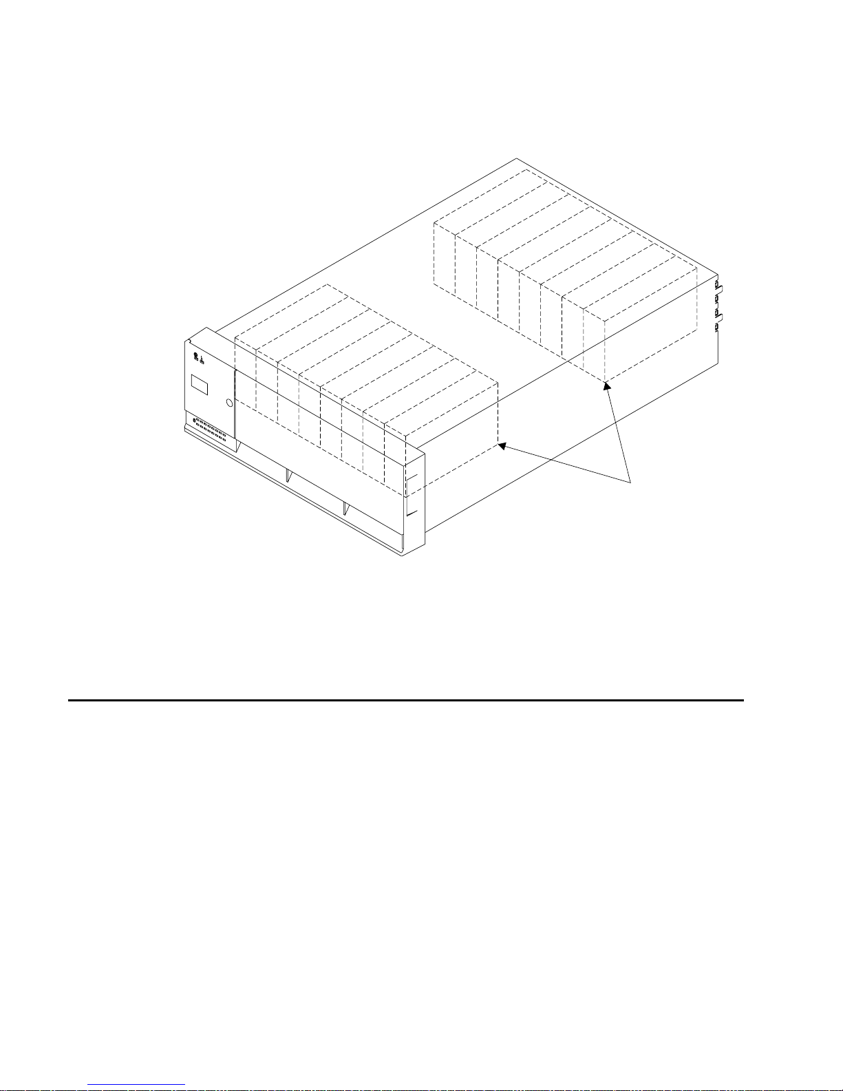
A fully configured 7133 Model D40 looks like this:
Disk drives
The whole of the front cover hinges downward to give access to the disk drive modules
installed at the front of 7133 units.
If your operating system implements the function, it can configure a 7133 Model D40, in
addition to the disk drives within it, as a device.
Deskside Unit Configurations
7133 Model T40 is a deskside SSA disk storage unit that can be attached to any
computer that provides support for SSA. Up to 16 SSA disk drive modules, in groups of
up to four, can be installed in a Model T40 unit.
Each group of disk drives in a 7133 unit is connected in a loop that must also contain
an SSA adapter. An SSA loop can also contain other groups of disk drives and
additional SSA adapters. The rules for connecting SSA loops and details of simple
configurations are described in the 7133 Model T40: Installation Guide.
With a 7133 Model T40, an Advanced SSA Optical Extender (Pair) feature can be
installed. This allows the 7133 unit to be connected by fibre optic cables to host
systems or other System units up to 10 km (32800 feet) away.
2 7133 Models D40 and T40 Operator Guide
|
|
|
Page 17
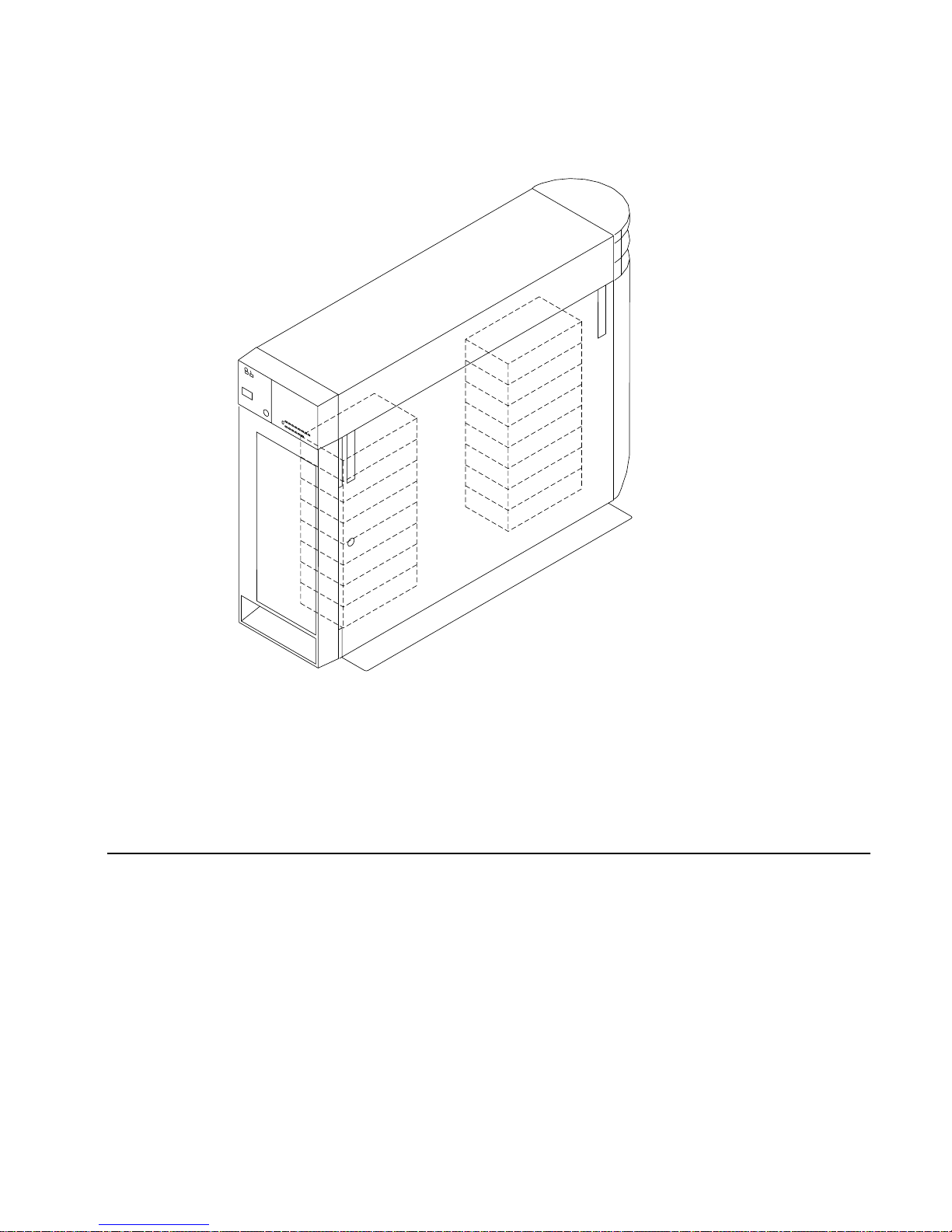
A fully configured 7133 Model T40 looks like this:
The front and back covers hinge to the left to give access to the disk drive modules
installed behind them. Locks are provided on the covers to prevent unauthorized access
to the disk drive modules and system connections.
If your operating system implements the function, it can configure a 7133 Model T40, in
addition to the disk drives within it, as a device.
Controls and Lights
This section describes the Power switch and lights on a 7133 Model D40 or T40 unit.
If you leave the 7133 Power switch set to on, power within a 7133 unit is turned on and
off automatically:
v For a Model D40, when you turn power on and off to the rack containing the unit
v For any 7133 model, if it has the Remote Power On Control feature installed, when
you turn power on and off to your system unit.
During normal operations, you do not need to check the lights on 7133 units.
Chapter 1. Using the Subsystems 3
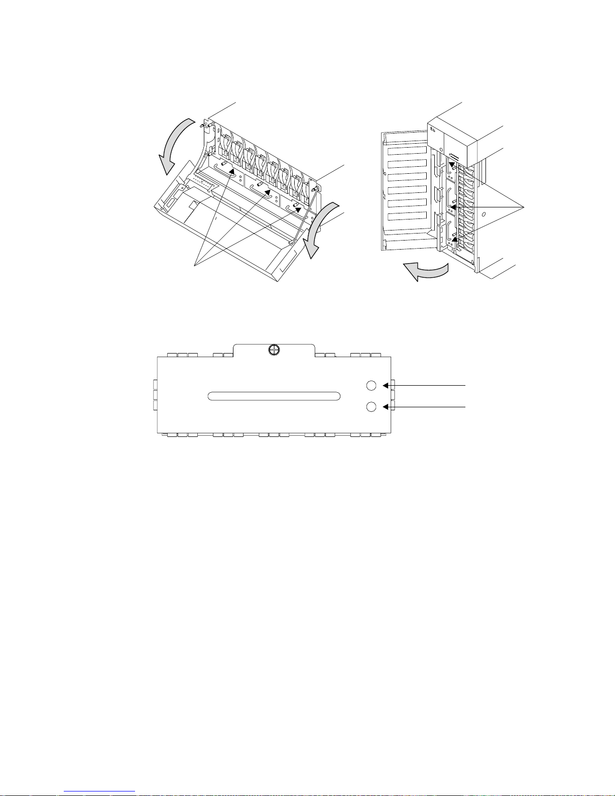
Page 18
Subsystem Controls
You can see the 7133 Subsystem lights at the front of each 7133 unit. The subsystem
Power switch and other controls are behind a flap on the front cover. To reach these,
push the latch button and hinge the flap to the left.
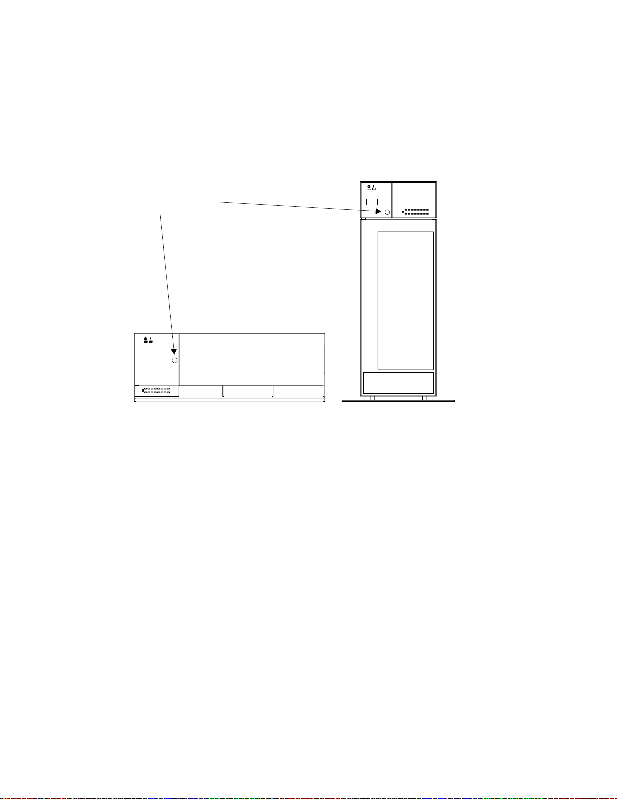
Latch button
Model D40 Model T40
4 7133 Models D40 and T40 Operator Guide
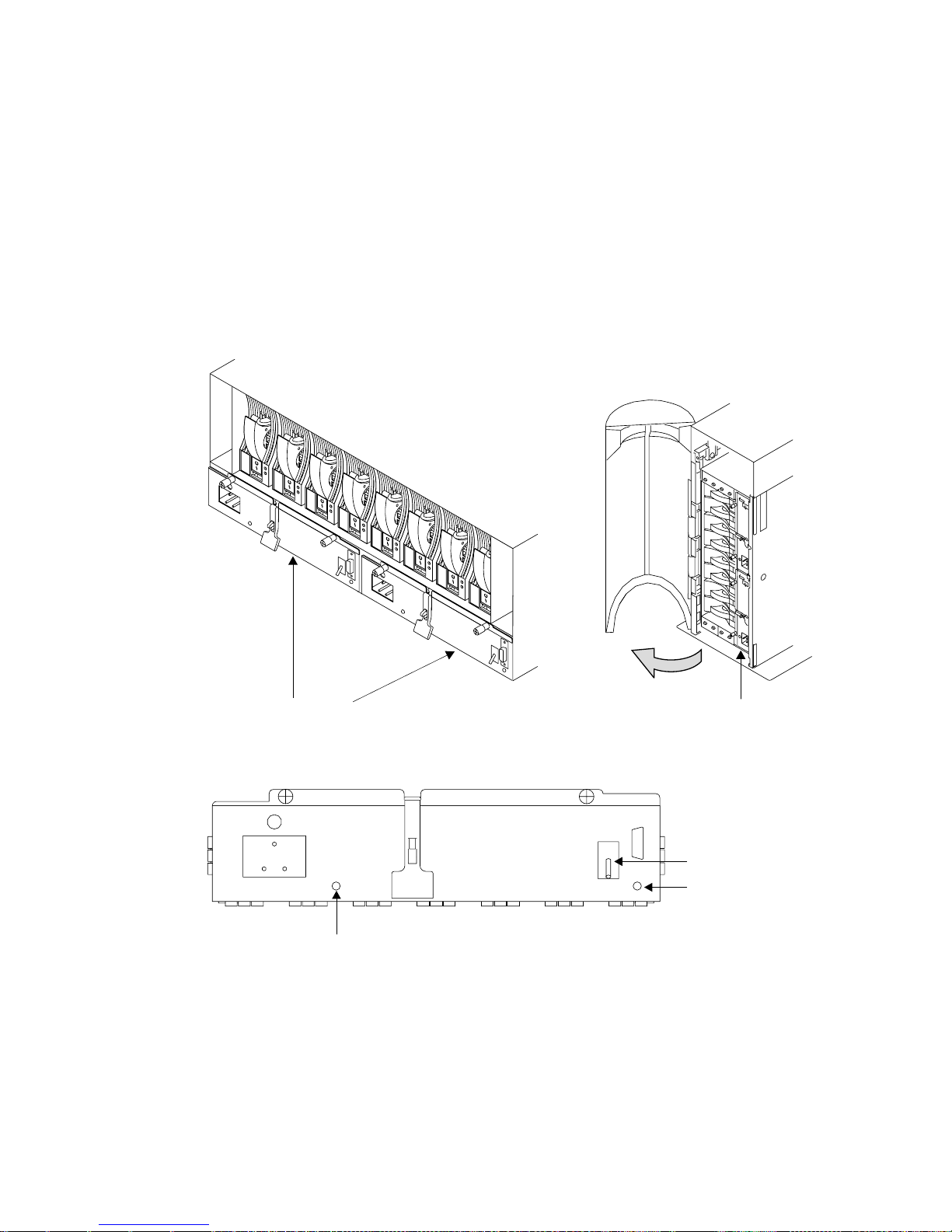
Page 19
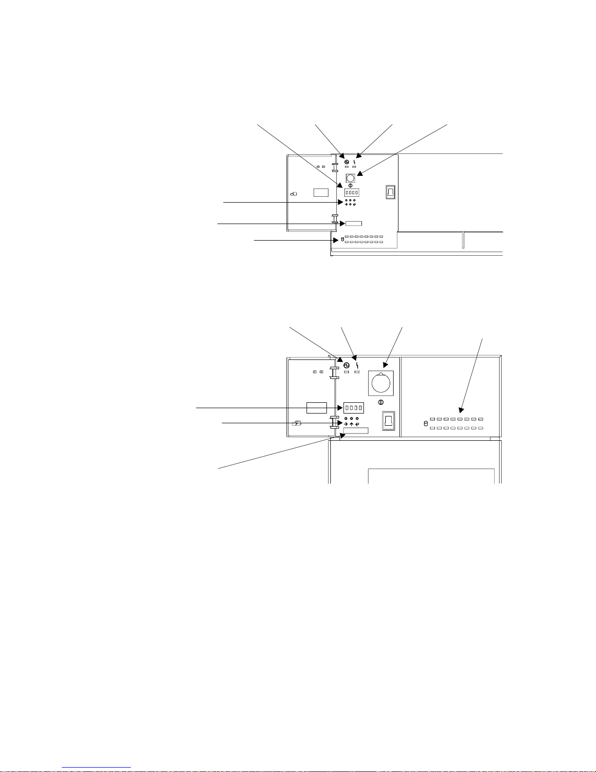
With the flap open, you can see all the controls:
Disk drive status lights
ID push buttons
ID display Power/Standby SwitchPower light
Check light
Disk drive
status lights
ID push buttons
ID display
Power switchPower light
Check light
Model D40
ModelT40
Serial Number
Serial Number
Power switch
In the 7133 Model D40, the Power switch, labeled Power/Standby, controls
electrical power from the power-supply units within the 7133 unit to the disk
drives and other components. To connect this internal electrical power, press
the Power switch. To remove this power, press the switch again. (When you
have pressed this switch to remove the internal power and the Power light is
flashing, mainline electrical power can still be present within the 7133
rack-mounted unit. To remove electrical power completely from the unit,
disconnect the mainline electrical supply.)
In the 7133 Model T40, the Power switch controls the main electrical power
into the 7133 unit. To connect main electrical power, press the Power switch.
To remove this power, press the switch again.
Chapter 1. Using the Subsystems 5
Page 20

Attention: Pressing these switches when the Power light is on can cause a
system fault unless you first make the disk drives within the 7133 unit
unavailable to the operating system. To do this:
1. Use the system-management task menus of the operating system to make
the disk drives unavailable to the system.
2. If the 7133 unit is connected to more than one adapter, make the disk
drives unavailable to the system or systems for each of the paths to the
system.
Power light
The Power light, which is green, comes on permanently when the
power-supply units within the 7133 subsystem are supplying power to the rest
of the subsystem. When the subsystem is in standby mode, this light will be
flashing. In standby mode, the power-supply units do not supply power to the
drives. This mode is set by the power/standby switch on the Model D40 or
remotely on either model if the remote power option is installed.
Check light
The Check light, which is amber, comes on if a failure occurs within the 7133
unit. The unit might be able to continue operating satisfactorily even when the
failure of a single part has been detected. The light can be set flashing by an
SSA service aid to identify the failing 7133.
ID display
The ID display is a four-character display that can be set by the three ID push
buttons.
This display normally shows the ID of the 7133 unit. If a failure occurs within
the 7133 unit, an error ID for the failure is shown, alternating with the ID of the
7133 unit; “Identifying 7133 Units” on page 14 describes these how to set the
7133 IDs, the 7133 Models D40 and T40 Serial Disk Systems: Service Guide,
GY33–0192–02, describes the error IDs.
ID push buttons
You can use these push buttons to set the ID of the 7133 unit that is shown in
the ID display. Use a ball-point pen or similar instrument to press these push
buttons.
v The left button steps through the four character positions, one position at a
time, to select the character position that you want to set.
v The center button steps through the available characters, one character at a
time, to select a character.
v The right button stores the selected ID.
If no push button is pressed within 10 seconds, the display resets to its last
valid setting.
6 7133 Models D40 and T40 Operator Guide
Page 21

Disk Drive Status lights
These 16 green lights show the status of the disk drives that are installed in
the 7133 unit. The upper row of lights relate to the disk drives that are installed
at the front of the unit, 1 through 8, from left to right. The lower row represents
the disk drives that are installed at the back of the unit, 9 through 16, from
right to left.
Each status light shows the following conditions:
Permanently on
Both SSA links to the disk drive are active, and the disk drive is ready
to accept commands from the using system.
Off Both SSA links to the disk drive are inactive because of one of the
following conditions:
v The disk drive modules, dummy disk drive modules, or SSA
adapters that should be connected to each side of this module are
missing or not connected.
v The disk drive modules or dummy disk drive modules that are
connected to each side of this module are inactive.
v An SSA adapter in the same SSA loop as this module is inactive.
v A power-on self-test (POST) is running on this disk drive.
Slow flash (two seconds on, two seconds off)
Only one of the SSA links to this disk drive module is active.
Fast flash (five times per second)
This disk drive module is active with a command in progress.
Disk Drive Module Lights
To see the lights on disk drive modules installed in the front part of a 7133 Model D40
or T40 unit:
v For a Model D40, open the front cover by pivoting it downward
v For a Model T40, open the front cover by:
1. If necessary, unlocking the cover using the key provided
2. Gripping the front cover on the right and pivoting it to the left.
Chapter 1. Using the Subsystems 7
Page 22
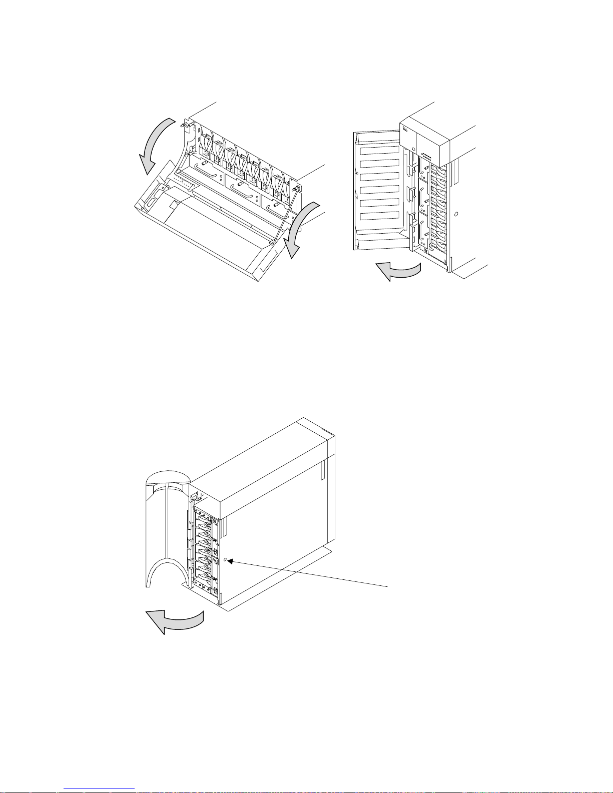
To see the lights on disk drive modules installed at the back of a 7133 Model D40 or
T40:
v For a Model D40, open the back door of the rack containing the 7133.
v For a Model T40, open the back cover of the 7133 by:
1. If necessary, unlocking the cover using the key provided
2. Gripping the back cover on the right and pivoting it to the left.
Lock
8 7133 Models D40 and T40 Operator Guide
Page 23
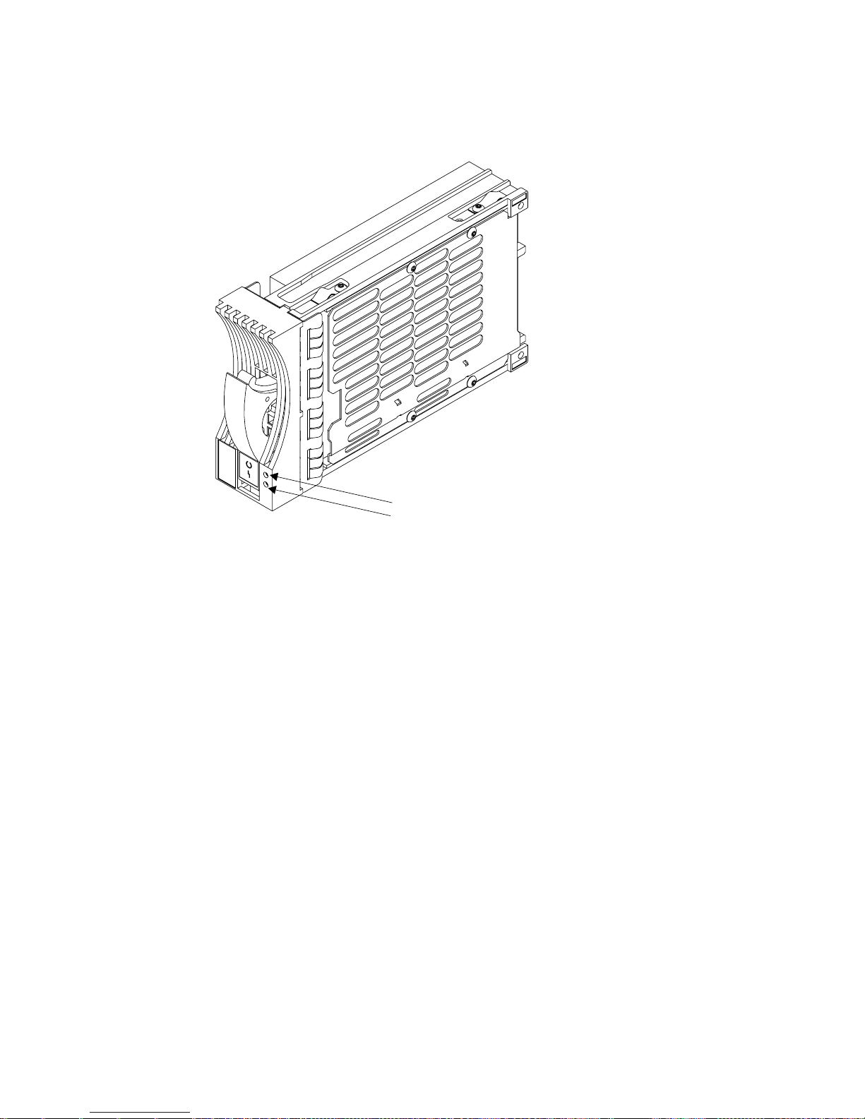
Each disk drive module has two lights.
Check Light
Ready Light
Ready light
The Ready light, which is green, shows the following conditions:
Permanently on
Both SSA links to the disk drive are active, and the disk drive is ready
to accept commands from the using system.
Off Both SSA links to the disk drive are inactive because of one of the
following conditions:
v The disk drive modules, dummy disk drive modules, or SSA
adapters that should be connected to each side of this module are
missing or not connected.
v The disk drive modules or dummy disk drive modules that are
connected to each side of this module are inactive.
v An SSA adapter in the same SSA loop as this module is inactive.
v A power-on self-test (POST) is running on this disk drive.
The Ready lights on the disk drive modules within a 7133 are
repeated on the front cover of the 7133, as the Disk Drive Status
lights.
Slow flash (two seconds on, two seconds off)
Only one of the SSA links to this disk drive module is active.
Fast flash (five times per second)
This disk drive module is active with a command in progress.
Chapter 1. Using the Subsystems 9
Page 24

The status light for this disk drive, at the front cover of the 7133 unit, shows
the same conditions as this light.
Check light
The Check light, which is amber, shows the following conditions:
Off Normal operating condition
Permanently On
One of the following conditions exists:
v An unrecoverable error that prevents the normal operation of the
SSA links to the disk drive has been detected.
v Neither SSA link to the disk drive is active.
v The power-on self-tests (POSTs) are running or have failed. The
light comes on as soon as the disk drive is switched on, and goes
off when the POSTs are completed successfully. If the light remains
on for longer than one minute after the disk drive is switched on,
the POSTs have failed.
v The disk drive is in service mode, and can be removed from the
7133 unit.
Flashing
The Check light has been set by an SSA service aid to identify the
position of this disk drive module.
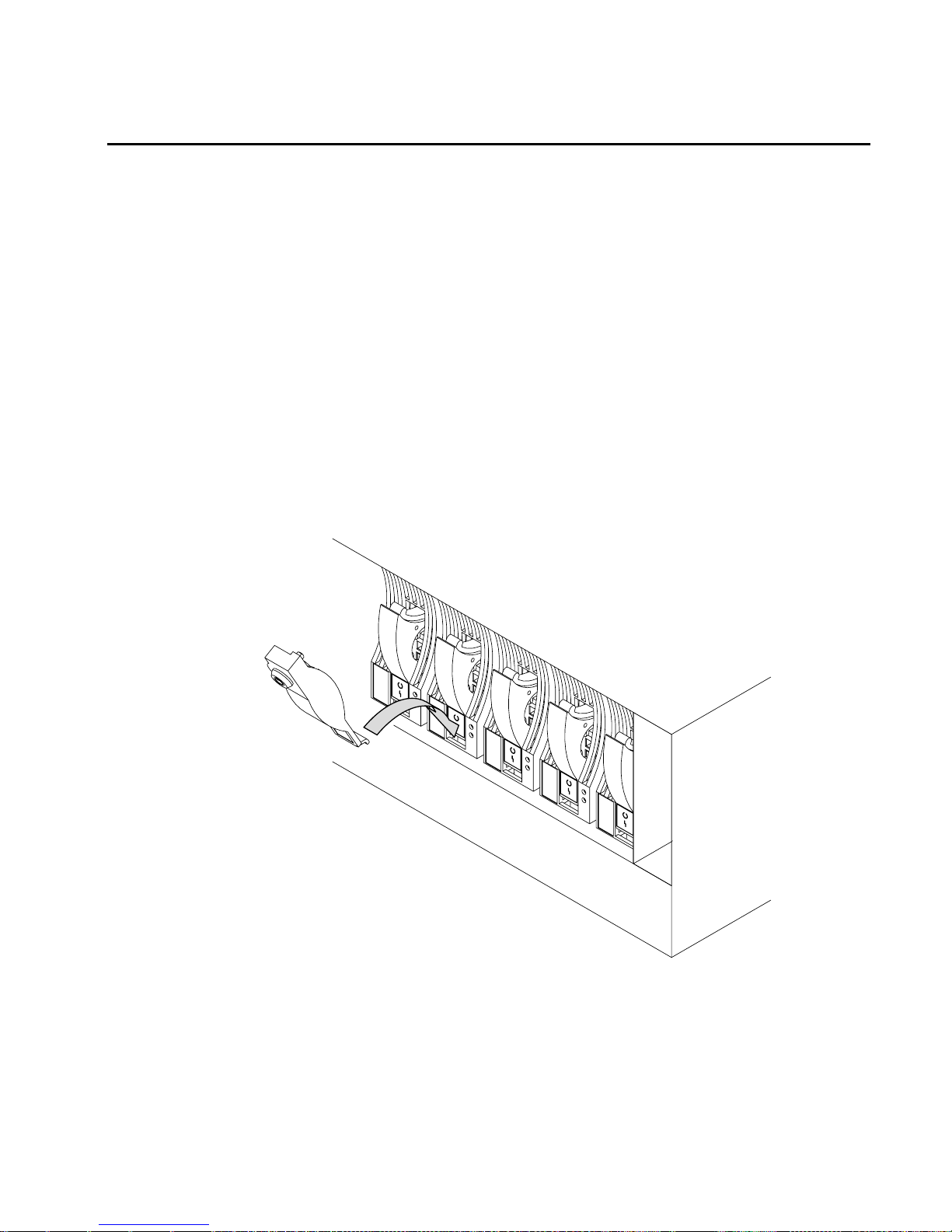
Fan Assembly Lights
Three fan assemblies are installed in the front of 7133 Models D40 and T40 units. To
see their lights:
v For a Model D40, open the cover of the 7133 by pivoting it downward.
v For a Model T40, open the front cover of the 7133 by:
1. If necessary, unlocking the cover using the key provided.
2. Gripping the front cover on the right and pivoting it to the left.
10 7133 Models D40 and T40 Operator Guide
Page 25
assemblies
Fan
assemblies
Fan
The fan assemblies have the following lights:
Check light
Power light
Power light
The Power light, which is green, comes on when the power supply is
connected to the fan assembly.
Check light
The Check light, which is amber, comes on and remains on if the fan assembly
fails.
Chapter 1. Using the Subsystems 11
Page 26
Power-Supply Assembly Lights and Switch
Two power-supply assemblies are installed in the back of 7133 Models D40 and T40
units. To see the power-supply assemblies:
v For a Model D40, open the back door of the rack containing the 7133.
v For a Model T40, open the back cover of the 7133 by:
1. If necessary, unlocking the cover using the key provided
2. Gripping the back cover on the right and pivoting it to the left.
Supply AssembliesSupply Assemblies
The power-supply assemblies have the following lights and switch:
PWR/FAULT RESET
CHK/PWR-GOOD
PWR light
PWR light
The Power light, which is green, comes on when the mainline power supply is
connected to the power-supply assembly.
CHK/PWR-Good light
This light can show one of two colors:
v Green, when electrical power is connected from the power-supply assembly
to the disk drives and other components in the 7133 unit.
12 7133 Models D40 and T40 Operator Guide
Page 27

v Amber, when the power-supply unit fails.
PWR/FAULT RESET switch
The PWR/FAULT RESET switch connects electrical power from the
power-supply assembly to the disk drives and other components in the 7133
unit.
Chapter 1. Using the Subsystems 13
Page 28

Identifying 7133 Units
During normal operations, the four-character ID display at the front of the 7133 Model
D40 or T40 unit shows the ID of the unit. (“Subsystem Controls” on page 4 shows the
position of the ID display.) You can set these IDs by using the three ID push buttons.
The four-character alphanumeric display may show the location and ID of the 7133. For
example, on a rack-mounted Model D40, you can use two digits to show the ID of the
rack, and two digits to show the ID of the 7133, while on a Model T40, you can use all
four digits to show the ID of the 7133. You can set the ID display to represent whatever
you require. The resulting ID must, however, be unique.
Identifying Disk Drive Modules
You can use an SSA service aid to make the Check light on a particular disk drive
module flash. The status light for that disk drive, at the front of the 7133 unit, also
flashes. The appendix for your system, later in this manual, describes how to do this.
You can identify a disk drive module by the serial number that appears on a label on
the front of the module:
Serial Number
14 7133 Models D40 and T40 Operator Guide
Page 29
Security
To protect your disk drives from unauthorized access, locks are provided on the covers
of deskside units and are available as accessories to secure individual disk drive
modules.
Disk Drive Module Locks
Disk drive module locks prevent the unauthorized removal of disk drive modules from
either rack-mounted units or deskside units. You need one lock for each disk drive
module that you want to secure.
Note: The disk drive module locks for use in 7133 Models D40 and T40 units are
different from the locks for use in 7133 Models 010, 02, 500, and 600 units.
To lock a disk drive module into a 7133 Model D40 or T40 unit:
1. Put the end of the lock into the hole at the bottom of the front of the disk drive
module.
Chapter 1. Using the Subsystems 15
Page 30
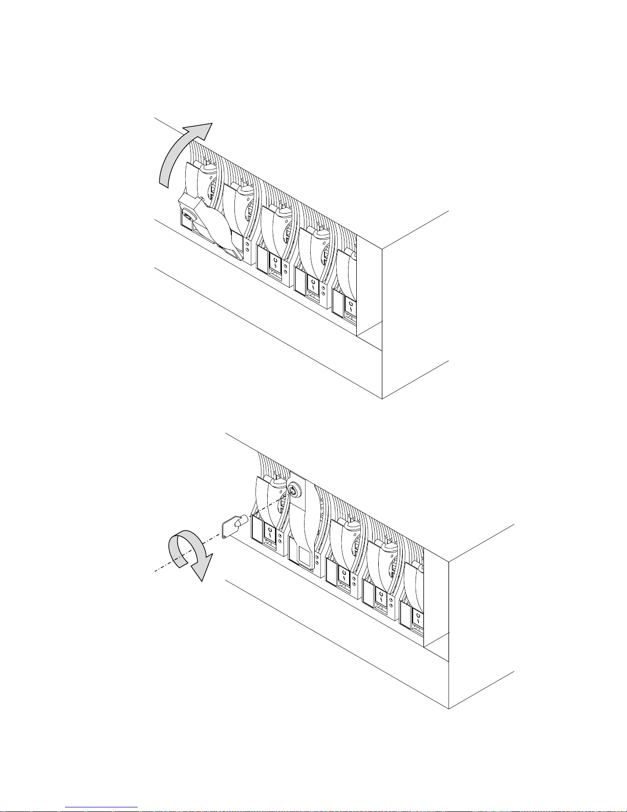
2. Push the lock up to the front of the disk drive module.
3. Put the key into the lock and turn the key clockwise half a turn.
16 7133 Models D40 and T40 Operator Guide
Page 31

Three keys, that fit all Models D40 and T40 locks, are supplied with the first lock that
you order. Keep at least one of these keys in a secure area.
Deskside Unit Cover Locks
On the 7133 Model T40, locks on the front and back covers provide physical security
for the drives and the connections to the system unit. You do not need to remove these
covers during normal operations. The two locks use the same key. If you lock the
covers, neither of them can be opened for servicing without the use of the key. You do
not need to lock the covers for them to stay closed.
Lock
Ordering Cover-Lock Keys
For protection against unauthorized key duplication, the cover locks are high-security
locks. Keys for these locks are a factory-restricted series and duplicate keys are not
available through normal commercial channels. The serial number of the lock is
stamped on each key; make a note of this number. The additional key supplied and
your note of its number should be stored in separate secure areas.
Make a copy of the official order form on the following page, fill in the details, and send
it to the address printed on the form. As a security precaution, the manufacturer will not
honor orders that are not on the official order form.
Chapter 1. Using the Subsystems 17
Page 32

If a lock becomes faulty, contact your sales representative for a replacement.
18 7133 Models D40 and T40 Operator Guide
Page 33

.
Key Reorder Form
This f
The cost per k
Please sho
Number of k
Ser
orm represents an authorized order for additional keys.
ey is $2.50 U.S. Or £2.00 (two pounds sterling).
w the quantity required and enclose a check or money order for the correct amount:
eys required _____________________
ial number of lock _____________________
Please type or print your return address:
Address _____________________________________________________________________________
City ________________________________________________________________________________
State __________________________________ Zip _______________________________________
Mail this for
Camloc
5623
Alsip
Illinois
U
m to:
k Systems Inc.
West 125th Street
60658
.S.A.
Or:
Camloc
3, P
Compton Industr
EASTBOURNE
Sussex
United Kingdom
BN23 6QE
k Systems
arkView
ial Estate
Note: No orders will be processed without this form.
Chapter 1. Using the Subsystems 19
Page 34

20 7133 Models D40 and T40 Operator Guide
Page 35

Chapter 2. Adding Disk Drive Modules
This chapter describes how to add disk drive modules to a 7133 Model D40 or T40 that
is already installed as part of your system.
You can do this only if:
1. You are authorized by your organization to do this.
2. You have the correct disk drive module. Only disk drive modules that have a blue
trigger behind the handle on the front can be installed in 7133 Model D40 or T40
units. The storage capacity of a disk drive module is shown on the label at the front
of the module:
Capacity
Blue
Note: Disk drive modules that can be installed in 7133 Model 010, 020, 500, or 600
units cannot be installed in 7133 Model D40 or T40 units.
Attention:
v Do not remove two disk drive modules from the subsystem at the same time.
v Disk drive modules are fragile. Handle them with care. Keep them well away from
strong magnetic fields.
You do not need to remove power from the 7133 unit when adding a disk drive module.
After you have added a disk drive module to a 7133 unit, you must add it into your
system software configuration by using the system programs.
21
Page 36

Before Adding a Disk Drive Module
1. Identify the slot for the new disk drive module using the configuration planning
information for your system. There should be a dummy disk drive module in the slot.
You can identify the disk drive modules that will be next to the new disk drive
module by using the Identify function in the SSA service aids. (The appendix for
your system, later in this manual, describes how to use this aid.) You cannot use
the Identify function to identify the dummy disk drive module itself because dummy
disk drive modules do not have lights or serial-number labels.
Important: Before you attempt to remove a dummy disk drive module, ensure that
the SSA loop that contains the dummy is complete. Failure to do this may result in
loss of access to other disk drives.
2. Open the front cover of the unit by gripping the cover at the sides and pivoting the
whole front cover downward.
If the slot for the new disk drive module is in a deskside unit, open the front or back
cover of the unit by:
a. If necessary, unlocking the cover using the key provided.
22 7133 Models D40 and T40 Operator Guide
Page 37

b. Gripping the right-hand edge of the cover and pivoting it to the left.
The illustrations in the following instructions show a rack-mounted unit. The steps for
adding a disk drive module to a deskside unit are the same, but the parts are turned
through 90 degrees.
Chapter 2. Adding Disk Drive Modules 23
Page 38

To Add a Disk Drive Module
1. Push downward on the blue trigger and pull outward the handle of the dummy disk
drive module. This action moves the module partly out of the slot.
2. Pull the dummy module out of the 7133 unit.
24 7133 Models D40 and T40 Operator Guide
Page 39

Attention: The fans may increase in speed. Do not leave the slot empty for more
than 30 minutes; if you do, the 7133 unit and the disk drive modules within it might
overheat and be damaged.
Chapter 2. Adding Disk Drive Modules 25
Page 40

3. With one hand supporting the new module, engage it in the groove and push it into
the slot from which you have just removed the dummy module.
The module stops before it is completely into the slot.
4. Close the handle of the module until it shuts with a click. This action pulls the
module completely into the slot.
26 7133 Models D40 and T40 Operator Guide
Page 41

5. Push on the front of the module to ensure that the module is fully home.
Attention: The fans may decrease in speed.
Chapter 2. Adding Disk Drive Modules 27
Page 42

6. Ensure that the Check light comes on immediately and that it goes out after
approximately 2 seconds. (If this does not happen, after checking that the new
module is properly installed, check the SSA error log for information about the
fault.)
Check
light
Ready
light
28 7133 Models D40 and T40 Operator Guide
Page 43

7. If you do not want to lock the new disk drive module into the unit, using the lock
and key that you can order as a feature of the unit, go to step 8 on page 31. To
use the lock:
a. Put the end of the lock into the hole at the bottom of the front of the disk drive
module.
Chapter 2. Adding Disk Drive Modules 29
Page 44

b. Push the lock up to the front of the disk drive module.
30 7133 Models D40 and T40 Operator Guide
Page 45

c. Put the key into the lock and turn the key clockwise half a turn.
8. If you have just added a disk drive module at the front of a rack-mounted unit, close
the front cover.
Chapter 2. Adding Disk Drive Modules 31
Page 46

9. If you have just added a disk drive module to a deskside unit, close the cover and,
if required, lock it with the key provided.
10. Add the new disk drive module into your system software configuration, using the
system programs.
32 7133 Models D40 and T40 Operator Guide
Page 47

Chapter 3. Moving a 7133 Model D40 or T40 Safely
Attention: Damage as a result of improper handling may void your equipment warranty.
Contact your service representative to obtain packing materials or assistance to prepare
your 7133 unit for moving.
You should not try to move a 7133 Model D40 rack-mounted unit yourself. Always
contact a trained service representative to do this for you.
If you want your system or deskside unit moved, contact a trained service
representative.
33
Page 48

34 7133 Models D40 and T40 Operator Guide
Page 49

Chapter 4. Dealing with Problems
This chapter describes what to do if you have a problem with a 7133 Model D40 or
T40, how to change a faulty disk drive module, fan assembly, or power-supply
assembly, and what information to provide when you report a problem with a 7133
Model D40 or T40 or a device installed in it.
Starting to Deal with Problems
How to start dealing with SSA problems depends on the system to which your 7133 unit
is attached. “Appendix A. Operating with RISC Systems” on page 71 describes what to
do if you are using RISC based systems. “Appendix B. Operating with PC Servers” on
page 85 describes what to do if you are using PC Servers.
Additional problem indications
If the 7133 check light is on, look at the four character display. This may be displaying
an Error ID alternating with the 7133 ID. The Error ID may be one of the following:
SLOT The 7133 controller has detected one or more unpopulated drive positions. All
positions must be populated with either a disk drive or a dummy disk drive
module. If any slot is unpopulated, correct the situation. If all positions are
populated, report the problem to your service organization.
FAN1, FAN2, or FAN3
The 7133 controller has detected a defective fan. Replace the defective fan
(see “Changing Fan Assemblies” on page 49 for how to do this) or report the
problem to your service organization.
PSU1 or PSU2
The 7133 controller has detected a defective power supply unit. Replace the
defective power supply unit (see “Changing Power-Supply Assemblies” on
page 56 for how to do this) or report the problem to your service organization.
COLD, COOL, WARM, HOT
The 7133 controller has detected an ambient temperature problem. Take
actions to correct this condition. If you consider that the detection report is
wrong, report the problem to your service organization.
Any other error ID or no error ID
Report the problem to your service organization.
35
Page 50

Changing Disk Drive Modules
In some circumstances, you can change a faulty disk drive module without the
assistance of a service representative. You can do this only if:
v You are authorized by your organization to do this.
v You have the correct disk drive module. Only disk drive modules that have a blue
trigger behind the handle on the front can be installed in 7133 units. The storage
capacity of a disk drive module is shown on the label at the front of the module:
Capacity
Blue
Note: Disk drive modules that can be installed in 7133 Model 010, 020, 500, or 600
units cannot be installed in 7133 Model D40 or T40 units.
Attention:
v Do not remove two disk drive modules from the subsystem at the same time.
v Disk drive modules are fragile. Handle them with care. Keep them well away from
strong magnetic fields.
You do not need to remove power from the 7133 unit when changing a disk drive
module.
After you have changed a disk drive module in an SSA Disk Subsystem, you must
restore it into your system using the system programs.
36 7133 Models D40 and T40 Operator Guide
Page 51

Before Changing a Disk Drive Module
1. Check the error log; the appendix in this book for your operating system describes
how to do this.
2. The error log contains records; each record includes a Service Request Number
(SRN).
If the SRN is in the following list, it means that a disk drive module has a fault that
can be corrected by exchanging the disk drive module for a new one:
Any SRN whose first character is ‘1’
80203
D0100
D0300
If the SRN is not in the list, do not change the disk drive module; call your
service representative and report the problem.
If the SRN is in the list, continue at the next step.
3. Find the failing disk drive module by using:
a. The location code supplied in the error log. You can find details of the location
code format in the appendix of this book that applies to your operating system.
b. The Identify function in the SSA service aids (the appendix in this book for your
operating system describes how to do this).
This service-aid function also describes the storage capacity of the failing disk
drive module. Always replace a disk drive module with one of the same capacity.
4. Important. Put the failing disk drive module into service mode. (the appendix in this
book for your operating system describes how to do this).
5. Check the lights on this disk drive module. (“Disk Drive Module Lights” on page 7
describes where these are and how to see them.)
If the check light is not on, you cannot change the disk drive module; call
your service representative and report the problem.
If the check light is on, change the disk drive module using the procedure in the
following section.
Chapter 4. Dealing with Problems 37
Page 52

To Change a Disk Drive Module
1. If the failing disk drive module is at the front of a Model D40 rack-mounted unit,
open the front cover of the unit by gripping the cover at the sides and pivoting the
whole front cover downward.
2. If the failing disk drive module is in a deskside unit, open the front or back cover of
the unit by:
a. If necessary, unlocking the cover, using the key provided.
b. Gripping the cover at the right and pivoting it to the left.
38 7133 Models D40 and T40 Operator Guide
Page 53

The illustrations in the following instructions show a rack-mounted unit. The steps
for changing a disk drive module in a deskside unit are the same, but the parts are
turned through 90 degrees.
3. If the disk drive module is not locked in the 7133 unit, go to step 4 on page 41.
Otherwise, to remove the lock:
a. Put the key into the lock and turn the key counterclockwise half a turn.
Chapter 4. Dealing with Problems 39
Page 54

b. Pull the lock down from the front of the disk drive module.
c. Lift the lock from the hole at the bottom of the front of the disk drive module.
40 7133 Models D40 and T40 Operator Guide
Page 55

4. Press downward on the blue trigger and pull outward the handle of the failing disk
drive module. This action moves the module partly out of the slot.
5. Carefully pull the module out of the 7133 unit. Support the module with your other
hand as you take it from the unit.
Chapter 4. Dealing with Problems 41
Page 56

Attention:The fan speed may increase. Do not leave the slot empty for more than
30 minutes; if you do, the 7133 unit and the disk drive modules within it might
overheat and be damaged.
42 7133 Models D40 and T40 Operator Guide
Page 57

6. With one hand supporting the new module, engage it in the groove and push it into
the slot from which you have just removed the failing module.
The module stops before it is completely into the slot.
Chapter 4. Dealing with Problems 43
Page 58

7. Close the handle of the module until it shuts with a click. This action pulls the
module completely into the unit. The fans may decrease their speed.
8. Push on the front of the module to ensure that the module is fully home.
44 7133 Models D40 and T40 Operator Guide
Page 59

9. Ensure that the Check light comes on immediately. If the module is not in Service
Mode, the Check light should go off after approximately 2 seconds. (If this does not
happen, check that the new module is properly installed, then check the SSA error
log for information about the new fault.)
If the module is in Service Mode, the light will stay on. Cancel the Service Mode
and the light should go out. See the appendix for your operating system for
information about the Service Mode. If the light stays on, check that the new module
is properly installed, then check the SSA error log for information about the new
fault.
If the Ready light comes on and remains on or flashes quickly (five times per
second), the drive has been installed properly, proceed to the next step.
If the ready light does not come on or flashes slowly (2 seconds on and 2 seconds
off), check the SSA error log for information about the new fault.
Check
light
Ready
light
Chapter 4. Dealing with Problems 45
Page 60

10. If you do not want to lock the new disk drive module into the unit, using the lock
and key that you can order as a feature of the unit, go to step 11 on page 48. To
use the lock:
a. Put the end of the lock into the hole at the bottom of the front of the disk drive
module.
46 7133 Models D40 and T40 Operator Guide
Page 61

b. Push the lock up to the front of the disk drive module.
c. Put the key into the lock and turn the key clockwise half a turn.
Chapter 4. Dealing with Problems 47
Page 62

11. If you have just changed a disk drive module at the front of a rack-mounted unit,
close the front cover.
12. If you have just changed a disk drive module in a deskside unit, close the cover
and, if required, lock it with the key provided.
13. Restore the disk drive module into your system using the system programs.
48 7133 Models D40 and T40 Operator Guide
Page 63

Changing Fan Assemblies
In some circumstances, you can change a faulty fan assembly without the assistance of
a service representative. You can do this only if:
v You are authorized by your organization to do this.
v You have a correct spare fan assembly.
Note: Fan-and-power-supply assemblies that can be installed in 7133 Model 010,
020, 500, or 600 units cannot be installed in 7133 Model D40 or T40 units.
Attention: Do not remove two fan assemblies from the subsystem at the same time.
You do not need to remove power from the 7133 unit when changing a fan assembly.
Before Changing a Fan Assembly
1. Perform the actions described in “Starting to Deal with Problems” on page 35.
2. If you have run diagnostics and obtained a Service Reference Number (SRN) and it
is in the following list, it means that a fan assembly has a fault that can be corrected
by exchanging the fan assembly for a new one:
SRN Component Fan position
80231 FAN1 Left (Top in a T40)
80232 FAN2 Middle
80233 FAN3 Right (Bottom in a T40)
If the SRN is not in the list, do not change the fan assembly: call your service
representative and report the problem.
Chapter 4. Dealing with Problems 49
Page 64

3. Check the lights on this fan assembly. (“Power-Supply Assembly Lights and Switch”
on page 12 describes these lights and how to see them.)
If the check light is not on, you cannot change the fan assembly; call your
service representative and report the problem.
If the check light is on, change the fan assembly using the procedure in the
following section.
To Change a Fan Assembly
The illustrations in the following instructions show a rack-mounted unit. The steps for
changing a fan assembly in a deskside unit are the same, but the parts are turned
through 90 degrees.
1. Loosen the captive bolt on the failing fan assembly by turning the thumbscrew
counterclockwise.
50 7133 Models D40 and T40 Operator Guide
Page 65

2. Pull the fan assembly from the unit.
Attention: Do not leave the space empty for more than 30 minutes; if you do, the
7133 unit and the disk drive modules within it might overheat and be damaged.
Caution: Do not insert hands or tools into the empty fan opening.
Chapter 4. Dealing with Problems 51
Page 66

3. Push the replacement fan assembly fully into the unit.
52 7133 Models D40 and T40 Operator Guide
Page 67

4. Tighten the captive bolt by turning the thumbscrew clockwise.
Chapter 4. Dealing with Problems 53
Page 68

5. Check that the green Power light comes on within 5 seconds. (If it does not, check
that the new fan assembly is properly installed. If correctly installed, report the
problem to your service organization.)
Power
light
54 7133 Models D40 and T40 Operator Guide
Page 69

6. If you have just changed a fan assembly in a rack-mounted unit, close the front
cover.
7. If you have just changed a fan assembly in a deskside unit, close the front cover
and, if required, lock it with the key provided.
Chapter 4. Dealing with Problems 55
Page 70

Changing Power-Supply Assemblies
In some circumstances, you can change a faulty power-supply assembly without the
assistance of a service representative. You can do this only if:
v You are authorized by your organization to do this.
v You have a correct spare power-supply assembly.
Note: Fan-and-power-supply assemblies that can be installed in 7133 Model 010,
020, 500, or 600 units cannot be installed in 7133 Model D40 or T40 units.
Note: The mainline power connector for the –48V has a different connector. If you
need to change a –48V power-supply assembly, follow the instructions in this
section.
You do not need to remove power from the 7133 unit when changing a power-supply
assembly.
Before Changing a Power-Supply Assembly
1. Perform the actions described in “Starting to Deal with Problems” on page 35.
2. If you have run diagnostics and obtained a Service Reference Number (SRN) and it
is in the following list, it means that a power supply assembly has a fault that can
be corrected by exchanging it for a new one:
SRN Component Fan position
80221 PSU1 Left (Bottom in a T40)
80233 PSU2 Right (Top in a T40)
56 7133 Models D40 and T40 Operator Guide
|
|
|
|
Page 71

If the SRN is not in the list, do not change the power supply assembly: call
your service representative and report the problem.
3. Check the lights on this power-supply assembly. (“Power-Supply Assembly Lights
and Switch” on page 12 describes these lights and how to see them.)
If the Check/Power-Good light is not showing amber, you cannot change the
power-supply assembly; call your service representative and report the
problem.
If the Check/Power-Good light is showing amber, change the power-supply
assembly using the procedure in the following section.
To Change a Power-Supply Assembly
The illustrations in the following instructions show a rack-mounted unit. The steps for
changing a power-supply assembly in a deskside unit are the same, but the parts are
turned through 90 degrees.
1. Set the Power switch on the power-supply assembly to Off, by moving it
downward.
Note: On early power supply assemblies, pull the switch outward and then move it
downward.
Chapter 4. Dealing with Problems 57
|
|
|
|
|
|
|
Page 72

2. Unplug the mainline power cable from the failing power-supply assembly. Also, if
you are changing the left-hand power-supply assembly, unplug the remote power
control cable, if present, from the power-supply assembly.
Caution: Ensure that the mainline power cable has been removed from the failing
power supply assembly before continuing.
58 7133 Models D40 and T40 Operator Guide
Page 73

3. Loosen the two captive screws by turning the thumbscrews counterclockwise until
the screws hang freely.
Chapter 4. Dealing with Problems 59
Page 74

4. Press the catch and lift the lever on the power-supply assembly. This action moves
the power-supply assembly partly out of the 7133 unit.
60 7133 Models D40 and T40 Operator Guide
Page 75

5. Pull the power-supply assembly from the unit. The fan speed may increase.
Attention: Do not leave the space empty for more than 30 minutes; if you do, the
7133 unit and the disk drive modules within it might overheat and be damaged.
Caution: Do not insert hands or tools into the empty power supply opening.
Chapter 4. Dealing with Problems 61
Page 76

6. Push the replacement power-supply assembly fully into the unit.
62 7133 Models D40 and T40 Operator Guide
Page 77

7. Push down the lever on the power-supply assembly. This action pulls the
power-supply assembly completely into the 7133 unit.
DANGER
Do not plug the power supply cord into the power supply unit until the
unit is completely installed and its retaining screws have been tightened.
Chapter 4. Dealing with Problems 63
Page 78

8. Tighten the two captive bolts by turning the thumbscrews clockwise.
64 7133 Models D40 and T40 Operator Guide
Page 79

9. Replug the mainline power cable into the new power-supply assembly. Also, if you
have just changed the left-hand power-supply assembly, replug the remote power
control cable, if present, into the power-supply assembly.
Chapter 4. Dealing with Problems 65
Page 80

10. Check that the green Power light comes on immediately. (If it does not, check that
the new power-supply assembly is properly installed and that you are connected to
the mainline power supply. If these are correct, report the problem to your service
organization.)
Check/PowerGood light
66 7133 Models D40 and T40 Operator Guide
Page 81

11. Set the Power switch on the new power-supply assembly to On, by moving it
upward. Check that the Check/Power-Good light shows green within 5 seconds. (If
it does not, check that the new power-supply assembly is properly installed. If it is,
report the problem to your service organization.) The fan speeds may also
decrease.
Note: On early power supply assemblies, pull the switch outward and then move it
upward.
Chapter 4. Dealing with Problems 67
|
|
|
|
Page 82

12. If you have just changed a power-supply assembly in a deskside unit, close the
back cover and, if required, lock it with the key provided.
68 7133 Models D40 and T40 Operator Guide
Page 83

Reporting Problems
When you report a problem with a 7133 Serial Disk system, or with a device mounted
in a SSA Disk Subsystem, it is important that you report the following information, in
addition to the error information (the SRN) given to you by your operating system:
The machine type number 7133
The machine model number xxx
The machine serial number xx-xxxxx
To see the machine serial number of a 7133 unit, open the flap on the front cover. To
do this, push the latch button and hinge the flap to the left.
Latch button
Model D40 Model T40
Chapter 4. Dealing with Problems 69
Page 84

With the flap open, you can see the serial number label:
Disk drive status lights
ID push buttons
ID display Power/Standby SwitchPower light
Check light
Disk drive
status lights
ID push buttons
ID display
Power switchPower light
Check light
Model D40
ModelT40
Serial Number
Serial Number
70 7133 Models D40 and T40 Operator Guide
Page 85

Appendix A. Operating with RISC Systems
This appendix describes how to use those SSA service aids that you need when
operating RISC systems to which 7133 Model D40 or T40 subsystems are attached.
Related Publications
v 7014 Model S00 Rack: Installation and Service Guide, SA38-0550
v 7015 Model R00 Rack: Installation and Service Guide, SA23-2744
v SSA Adapters: User’s Guide and Maintenance Information, SA33-3272
v Advanced SerialRAID Adapter: User’s Guide and Maintenance Information,
SA33-3285
Are You Using the Correct Book? Do not use this book if you are operating a 7133
Model 010, 020, 500, or 600 SSA Disk Subsystem. For those models, use the 7133
SSA Disk Subsystem: Operator Guide, GA33-3259–01.
Web Support Pages
When performing SSA device or subsystem planning, installation, upgrades, or
preventive maintenance, please refer to the following web support pages. These pages
should also be reviewed in preparation for system hardware or operating system
upgrades if SSA devices are included in the configuration. These web pages provide
access to the latest SSA publications and support code for the using system, SSA
adapters and SSA subsystems.
http://www.hursley.ibm.com/ssa/ - Contains links to SSA publications and other SSA
web pages, including the ones below.
http://www.hursley.ibm.com/ssa/rs6k/ - Contains lists of the latest SSA support code
and provides download capability for the RS/6000 and AIX environments.
http://www.hursley.ibm.com/ssa/pcserver/ - Contains lists of the latest SSA support
code and provides code download capability for PC Server environments.
Starting SSA Service Aids
How to start the SSA Service Aids, and more information about the service aids, is
described in the manual supplied with your SSA adapter.
Identifying 7133 Models D40 and T40 Units and Disk Drive Modules
You can identify a 7133 Model D40 or T40 unit and the disk drive modules installed in it
either by the location code contained in system messages that refer to that unit, or by
using the SSA service aids.
71
|
|
|
|
|
|
|
|
|
|
|
|
|
|
|
|
|
|
|
|
|
|
|
|
|
Page 86

Location Code Format for 7133 systems
See “Location Codes” in the operator guide for your system for general information
about location codes.
Pdisks, Hdisks, and Disk Drive Module Identification
The physical disk drives (pdisks) in an SSA subsystem can be configured as logical
units (LUNs). A LUN is also known as an hdisk, and can consist of one or more
physical disk drives. An hdisk in an SSA subsystem might, therefore, consist of one
pdisk or several pdisks.
The configuration software also allocates an identification (hdisk and pdisk number) to
each disk drive module during the configuration of the SSA loop. The disk drive
modules do not have fixed physical addresses.
The numeric identifiers of pdisks, hdisks, and the disk drive module slots of a 7133 are
not related to each other. For example, pdisk1 is not necessarily installed in slot 1 of
the 7133.
The system software recognizes the disk drive module by a machine-readable number
that is written on the electronics card of the disk drive module. This number is shown
also on the label at the front of a disk drive module. The service aids show the number
as the last eight digits of the IEEE 16-digit SSA unique identifier (UID).
Service actions are always related to physical disk drives. For this reason, errors that
occur on SSA disk drives are always logged against the physical disk drive (pdisk).
AB CD EF IGJH---
Expansion adapter position
System I/0 Bus identifier
Disk drive module number
1 through 16 (decimal)
Enclosure ID
(the four characters that appear in
the display at the front of the 7133 unit)
Expansion drawer
Adapter position
(number of the slot, 1 through 8,
containing the SSA adapter)
72 7133 Models D40 and T40 Operator Guide
Page 87

If a disk drive that has been formatted on a machine of a particular type (for example, a
Personal System/2) is later installed into a using system that is of a different type (for
example, an RS/6000), that disk drive is configured only as a pdisk during the
configuration of the using system.
Identifying a subsystem or Disk Drive Module and Using Service Mode
Subsystems are identified by the disk drive modules contained in them.
To identify a disk drive module:
1. Start the system diagnostic programs.
2. From the Function Selection menu, select Service Aids.
3. This displays the Service Aids menu.
From this menu, select SSA Service Aids.
4. This displays the SSA Service Aids menu; select Set Service Mode.
SSA SERVICE AIDS 802380
Move cursor onto selection, then press Enter.
Set Service Mode
Link Verification
Configuration Verification
Format Disk
Certify Disk
F3=CANCEL F10=EXIT
5. This displays the Set Service Mode menu:
Appendix A. Operating with RISC Systems 73
Page 88

SET SERVICE MODE 802381
Move cursor onto selection, then press Enter.
<TOP>
systemname:pdisk0 1234567 2 GB SSA C Physical Disk Drive
systemname:pdisk1 1234568 2 GB SSA C Physical Disk Drive
systemname:pdisk2 1234567 2 GB SSA C Physical Disk Drive
> systemname:pdisk3 1234560 2 GB SSA C Physical Disk Drive
systemname:pdisk4 1234561 2 GB SSA C Physical Disk Drive
systemname:pdisk5 1234562 2 GB SSA C Physical Disk Drive
systemname:pdisk6 1234563 2 GB SSA C Physical Disk Drive
systemname:pdisk7 1234564 2 GB SSA C Physical Disk Drive
<BOTTOM>
F3=CANCEL F10=EXIT
On this screen, the fields in the first row, for example, are:
systemname
Name of the using system that the disk drives are connected to.
pdisk0 The name by which the system programs refer to the disk drive.
74 7133 Models D40 and T40 Operator Guide
Page 89

1234567
The serial number of the disk drive module; this number appears on the
front of the module:
Serial Number
2 GB SSA ...
A variable description of the disk drive.
Select the disk drive you want to identify.
6. The Set Service Mode menu is displayed:
Appendix A. Operating with RISC Systems 75
Page 90

SET SERVICE MODE 802382
> systemname:pdisk3 1234560 2 GB SSA Physical Disk
Move cursor onto selection, then press Enter.
+ Set/Reset Identify.
Select this option to set or reset the Identify indicator
on the disk drive
> Set/Reset Service Mode.
Select this option to set or rest Service Mode
on the disk drive.
ENSURE THAT NO OTHER HOST SYSTEM IS USING THIS DISK DRIVE
BEFORE SELECTING THIS OPTION
F3=CANCEL F10=EXIT
Select Set/Reset Identify.
The check light on the disk drive module that you have selected (and the
Subsystem Check light at the front of the 7133 unit) flashes.
Check that the serial number on the disk drive module matches the one that you
selected.
You can select and identify more than one disk drive at a time.
7. If you are going to change the disk drive module:
a. If the disk drive is a member of an array, and you are not using the disk as an
rhdisk, remove the disk from the array using the array configuration utility. (The
SSA Adapters: User’s Guide describes how to do this.)
b. Select Set/Reset Service Mode in this menu. (For some severe errors, this
might cause an error message to appear; ignore this message.) The Check light
on the disk drive module (and the Subsystem Check light at the front of the
7133 unit) should now be on and remain on. The disk drive is in service mode.
You can now change the disk drive module, using the steps described in “To
Change a Disk Drive Module” on page 38.
If the Check light is not on, you cannot change the disk drive module; call your
service representative and report the problem.
Only one disk drive can be in service mode at a time.
76 7133 Models D40 and T40 Operator Guide
Page 91

When you have finished using the service aid, select Set/Reset Identify or Set/Reset
Service Mode again. This turns off the Check light on the disk drive module and, if the
disk drive was in service mode, releases the disk drive for use by the system programs.
Problem Determination
If you have a problem with a 7133, see the operator guide for your system for a
description of what to do.
For some problems, your system diagnostics tell you to check the lights on the system
to discover which part, if any, has a fault. “Controls and Lights” on page 3 of this book
shows the position of the lights. The diagnostic programs tell you what to report to your
service representative. (“Reporting Problems” on page 69 describes other information
you should report.)
Checking the SSA Error Log
In RISC systems, when you start the diagnostic programs they automatically check the
SSA error log and present messages about any new problems that have been recorded
there. Your using system manuals describe how to start the diagnostic programs.
Service Aids
This section shows the screens for the service aids that are available when the 7133 is
attached to a RISC system.
Appendix A. Operating with RISC Systems 77
Page 92

Physical Link Configuration
01|PHYSICAL LINK CONFIGURATION xxxxx
02|
03|SSA Link Configuration for:
04| severn:ssa0 00-05 SSA Network RAID Adapter
05|
06| Link Port Device Location Port Link
07|
08| severn:ssa0 00-05 A1
09| pdisk9 00-05-P
10| pdisk10 00-05-P
11| pdisk11 00-05-P 20-C
12| 20-C || pdisk12 R1E1-01 40-I
13| 40-I pdisk13 R1E1-02 40-I
14| 40-I pdisk14 R1E1-03 40-I
15| 40-I pdisk15 R1E1-04 >> 40-I
16| 40-I >> pdisk16 R1E1-05 40-I
17| 40-I pdisk17 R1E1-06 40-I
18| 40-I pdisk18 R1E1-07 |||| 40-0
19| 40-O A1 trent2:**** A2 40-C
| ?????????????????????????????????????????????????????????????????????????????
| NONE OOOO **** FRED-09 40-I
| 40-I pdisk30 FRED-10 >>>> 40-I
| 40-I >>>> pdisk19 FRED-13 40-I
| 40-I pdisk20 FRED-14
| 40-I pdisk21 FRED-15 || 40-C
| 40-C A2 severn:ssa0 00-05
|
| severn:ssa0 00-05 B1
| 40-C || pdisk22 R1E1-09 40-I
| 40-I pdisk23 R1E1-10 40-I
| 40-I pdisk24 R1E1-11 40-I
| 40-I >> pdisk25 R1E1-12 || 40-C
| 40-C B2 severn:ssa0 00-05
23|
24| F3=Cancel F10=Exit
25|
Lines 7 through 22 are selectable and scrollable.
Keys to Use
v Press Enter to display the legend as a popup menu.
v Press the Cancel key to return to the Adapter Selection menu.
v Press the Exit key to return to the Service Aid Selection menu.
Legend for Screen Symbols
**** Unknown disk drive or adapter.
|| Inline mode.
|||| Forced Inline mode.
>> Automatic mode.
>>>> Forced Bypass mode.
OOOO Forced Open mode.
NONE No connection.
78 7133 Models D40 and T40 Operator Guide
Page 93

20-C 20 MB per second copper cable.
40-C 40 MB per second copper cable.
40-I 40 MB per second internal link.
40-O 40 MB per second optical link.
??????
Break in the SSA loop.
Enclosure Configuration
01|ENCLOSURE CONFIGURATION XXXXXX
02|
03|SSA Enclosure Configuration for:
04| R1E1 Enclosure 1 SSA Enclosure
05|
06| Conn Port Link Device Location Exchanged
07|
08| 20-C 1 || BYPASS
09| severn:pdisk01 01 X
10| severn:pdisk02 02
11| severn:pdisk03 03
12| severn:pdisk04 04
13| 4 >> BYPASS
14| 5 >> BYPASS
15| severn:pdisk05 05
16| severn:pdisk06 06
17| DDDD 07
18| severn:pdisk07 08 X
19| 40-C 8 || BYPASS
20| 9 OOOO BYPASS
| DDDD 09
| DDDD 10
| DDDD 11
| ---- 12
| 12 OOOO BYPASS
| 40-O 13 |||| BYPASS
| SSA Disk 13
| SSA Disk 14
| --- 15
| SSA Disk 16
| 40-O 16 |||| BYPASS
23|
24| F3=Cancel F10=Exit
25|
Lines 7 through 22 are selectable and scrollable.
Keys to Use
v Press Enter to display the legend as a popup menu.
v Press the Cancel key to return to the Enclosure Selection (configuration) menu.
v Press the Exit key to return to the Service Aid Selection menu.
Legend for Screen Symbols
X “Exchanged” flag. When set this flag indicates that the FRU has been removed
and reinstalled or exchanged for a new FRU since the flag was last reset.
Appendix A. Operating with RISC Systems 79
Page 94

–––– No disk drive module.
DDDD Dummy disk drive module.
BYPASS
SSA node bypass card.
|| Inline state.
|||| Forced Inline state.
>> Bypass state.
>>>> Forced Bypass state.
OOOO Forced Open state.
20-C 20 MB per second copper cable.
40-C 40 MB per second copper cable.
40-I 40 MB per second internal link.
40-O 40 MB per second optical link.
SSA Disk
Unconfigured disk drive.
Enclosure Environment
01|ENCLOSURE ENVIRONMENT XXXXXX
02|
03|SSA Enclosure Environment for:
04| R1E1 Enclosure 1 SSA Enclosure
05|
06| Enclosure Element Status
07|
08| Power Unit 1 Good
09| Power Unit 2 Fault (exchanged)
10|
11| Fan Unit 1 Good
12| Fan Unit 2 Good
13| Fan Unit 3 Fault
14|
15| Operator Panel Not Present
16|
17| Remote Power Off Module (RPO) Good
18|
19| Ambient Temperature (degrees Celsius) 35
20|
21| Controller Fault
22|
23|
24| F3=Cancel F10=Exit
25|
Note: In this screen the word “exchanged” indicates that the FRU has been removed
and reinstalled or exchanged for a new FRU since the Exchange flag was last
reset.
80 7133 Models D40 and T40 Operator Guide
Page 95

Keys to Use
v Press Enter to return.
v Press the Cancel key to return to the Enclosure Selection (environment) menu.
v Press the Exit key to return to the Service Aid Selection menu.
Enclosure Settings
2 01│ENCLOSURE SETTINGS
3 02│
4 03│Move cursor onto selection, then press <Enter>
5 04│
6 05│ ID DISPLAY
7 06│ BYPASS MODES
8 07│ TEMPERATURES WARNING
9 08│ COMPONENT EXCHANGED FLAGS
0 09│ DRIVE EXCHANGED FLAGS
1 10│
2 11│
3 12│
4 13│
5 14│
6 15│
7 16│
8 17│
9 18│
0 19│
1 20│
2 21│
3 22│
4 23│
5 24│ F3=Cancel F10=Exit
6 25│
Lines 6 through 22 are selectable.
Keys to Use
v Press Enter to go to the selected menu.
v Press the Cancel key to return to the Enclosure Selection (settings) menu.
v Press the Exit key to return to the Service Aid Selection menu.
Appendix A. Operating with RISC Systems 81
Page 96

Command Line Tools
ssaencl Command
Purpose
To allow the monitoring and changing of the status for SSA SES disk enclosures
(subsystems).
Syntax
To display enclosure component settings:
ssencl -l name [-s] [-v] [-i] [-b [card]*] [-t [threshold]*]
[-a] [-f [fan]*] [-d [drive_bay]*] [-p [PSU]*]
[-o] [-c]
To modify enclosure component settings:
ssencl -l name [[-I ID] [-U]] [-B [mode | card=mode*] [-S [d [drive_bay]*] | [b [card]*] | [p [PSU]*]|r|c|
For help, type: ssaencl -? or ssaencl -h
Description
The ssaencl command can be used to observe the existing settings of an SSA SES
disk enclosure (subsystem), or to modify the settings of that enclosure. The command
can be used only to observe or modify settings; it cannot be used to observe and
modify settings at the same time.
When the command displays enclosure settings, it displays them in tables that the user
can read easily. If the -s flag is specified, however, the command displays the settings
in colon-separated format, as used by commands such as the SMIT commands.
Flags
-l name
Specifies the name of an SSA SES enclosure or pdisk. If a pdisk name is
used, that pdisk must be in an SSA SES enclosure.
-s Displays output in colon-separated format.
-v Displays also VPD information.
-i Displays the enclosure identifier (as shown in the operator panel, if present).
-b [card]
Displays the status of the bypass cards. If no parameters are given, the status
for all the bypass cards is displayed. Valid values for the [card] parameter are:
1, 4, 5, 8, 9, 12, 13, 16.
-t [threshold]
Displays all the temperature thresholds, or only the specified temperature
thresholds. The valid values for the [threshold] parameter are:
lowarn The low-temperature warning threshold.
82 7133 Models D40 and T40 Operator Guide
Page 97

locrit The low-temperature critical threshold.
hiwarn The high-temperature warning threshold.
hicrit The high-temperature critical threshold.
-a Displays the ambient temperature of the enclosure and temperature threshold
statuses.
-f [fan] Displays the status of all the fans, or of only the specified fans. Valid values for
the [fan] parameter are: 1, 2, 3, and so on.
-d [drive_bay]
Displays the status of all the disk drive bays (slots), or of only the specified
disk drive bays. Valid values for the [drive_bay] parameter are: 1, 2, 3, and so
on.
-p [PSU]
Displays the status of all the power supply assemblies, or of only the specified
power supply assemblies. Valid values for the [PSU] parameter are 1, 2.
-o Displays the status of the operator panel.
-c Displays the status of the controller card.
-I ID[-U]
Modifies the enclosure ID. The ID must be a four-character alphanumeric
string. The optional -U flag causes the object data manager (ODM) to be
updated to show the change.
-B mode
Modifies all bypass cards to the given mode.
-B card=mode
Modifies the specified bypass cards to be in the given modes. The valid values
for the mode parameter are:
v Automatic
v Bypass
v Inline
v Open
Valid values for the card parameter are 1, 2, 3, 4, and so on.
-S Resets the “exchanged” flag of the selected FRU.
-T threshold=value
Modifies the specified temperature thresholds to the given values. The valid
values for the [threshold] parameter are:
lowarn The low-temperature warning threshold.
hiwarn The high-temperature warning threshold.
The value parameter is a temperature in degrees C.
Appendix A. Operating with RISC Systems 83
Page 98

Examples
v To display the status of all bypass cards on enclosure0, give the command:
ssaencl -l enclosure0 -b
v To display the status and VPD of the controller card in enclosure0, give the
command:
ssaencl -l enclosure0 -c -v
v To modify the ID for enclosure0 to R2D2, give the command:
ssaencl -l enclosure0 -I R2D2
v To display the contents of disk bay (slot) 8 in enclosure0, give the command:
ssaencl -l enclosure0 -d 8
84 7133 Models D40 and T40 Operator Guide
Page 99

Appendix B. Operating with PC Servers
This appendix describes how to use those SSA service aids that you need when
operating PC servers to which 7133 Model D40 or T40 subsystems are attached.
Related Publications
v IBM PC Servers: IBM Advanced SerialRAID/X Adapter: Installation and User’s Guide
and Maintenance Information, SA33-3288
v IBM Netfinity Rack: Planning and Installation Guide, S24L-8055
Are You Using the Correct Book? Do not use this book if you are operating a 7133
Model 010, 020, 500, or 600 SSA Disk Subsystem. For those models, use the IBM
7133 SSA Disk Subsystem for PC Servers: Operator Guide, GA33–3259–01.
Web Support Pages
When performing SSA device or subsystem planning, installation, upgrades, or
preventive maintenance, please refer to the following web support pages. These pages
should also be reviewed in preparation for system hardware or operating system
upgrades if SSA devices are included in the configuration. These web pages provide
access to the latest SSA publications and support code for the using system, SSA
adapters and SSA subsystems.
http://www.hursley.ibm.com/ssa/ - Contains links to SSA publications and other SSA
web pages, including the ones below.
http://www.hursley.ibm.com/ssa/rs6k/ - Contains lists of the latest SSA support code
and provides download capability for the RS/6000 and AIX environments.
http://www.hursley.ibm.com/ssa/pcserver/ - Contains lists of the latest SSA support
code and provides code download capability for PC Server environments.
Service Aids
All service aids for PC servers are provided by the Remote Systems Management
(RSM) configurator, which is supplied with the SSA adapter
The Installation and User’s Guide for your SSA adapter describes how to start the SSA
service aids.
The RSM configurator is a Web Browser utility. It contains online help, and gives
access, locally and remotely, to the following subsystem functions:
v Configuration facilities that allow you to:
– Configure SSA disk drive modules to the using (host) system (see the user and
service information for your SSA adapter).
85
|
|
|
|
|
|
|
|
|
|
|
|
|
|
|
|
|
|
|
|
|
|
|
Page 100

– Configure, create, and delete SSA RAID arrays (see the user and service
information for your SSA adapter).
v Error log analysis (see the user and service information for your SSA adapter).
v Service functions
The service functions that the RSM provides for a selected adapter are:
v Display a Logical View of the SSA network
v Display a Physical View of the SSA network
v View a selected 7133 Model D40 or T40 enclosure
v Check all microcode levels
The Enclosure View provides the following enclosure functions:
v Display:
– ID (name) of the enclosure
– FRUs that are installed
– VPD of each FRU
– Status of each FRU:
- Fault bit
- Exchange or Swap bit
- Connection type (for example, bypass cards)
– Ambient temperatures
– Warning-temperature settings
– Physical position of each disk drive module
– Mode and state of each bypass card
v Modify:
– ID (name) of the enclosure
– Warning-temperature settings
– Mode of each bypass card
Identifying 7133 Models D40 and T40 Units and Disk Drive Modules
You can identify a 7133 Model D40 or T40 unit and disk drive modules installed in it
either by the location code contained in system messages that refer to that unit, or by
using the SSA service aids.
Location Code Format for 7133 systems
The format of this code is NNNN — XX where NNNN is the enclosure ID, the four
characters that appear in the display at the front of the 7133 operator panel, and XX is
the disk drive slot number and has a value of 1 to 16.
86 7133 Models D40 and T40 Operator Guide
 Loading...