

Page 1

ERserver
iSeries
43xx Disk Unit,
71xx Disk Expansion Unit,
71xx Disk Unit Enclosure
Version 5
Page 2

Page 3

ER s e r v e r
iSeries
43xx Disk Unit,
71xx Disk Expansion Unit,
71xx Disk Unit Enclosure
Version 5
Page 4

Note
Before using this information and the product it supports, be sure to read the information in
“Notices,” on page 71.
Fourth Edition (August 2005)
®
This edition applies to version 5, release 3, modification 0 of IBM Operating System/400
(product number
5722–SS1) and to all subsequent releases and modifications until otherwise indicated in new editions. This version
does not run on all reduced instruction set computer (RISC) models nor does it run on CISC models.
© Copyright International Business Machines Corporation 2000, 2005. All rights reserved.
US Government Users Restricted Rights – Use, duplication or disclosure restricted by GSA ADP Schedule Contract
with IBM Corp.
Page 5

Contents
Chapter 1. 43xx or 71xx disk unit . . . .1
Before you begin . . . . . . . . . . . . .1
Chapter 2. Replace 43xx disk units . . .3
Replace 43xx RAID or Mirrored protected disk units
with system powered on . . . . . . . . . .3
Replace 43xx RAID or Mirrored protected disk units
with system powered off . . . . . . . . . .8
Chapter 3. Install 43xx disk units . . .15
Install 43xx disk units with system power on . . .15
Details: Install 43xx disk units with system
power on . . . . . . . . . . . . . .16
Install 43xx disk units with system power off . . .20
Details: Install 43xx disk units with system
power off . . . . . . . . . . . . . .21
Open or remove the front cover . . . .29
270, 800, 810, 820, or 5075 front cover . . . . . .29
825 front cover . . . . . . . . . . . . .30
270, 800, or 810 in a rack . . . . . . . . . .31
830, 840, 870, 890, 5074, 5079, 5094 or 5095 . . . .32
Disk unit locations . . . . . . . . .33
270, 800, or 810 system unit . . . . . . . . .33
7104 or 7116 expansion unit . . . . . . . . .34
820 system unit . . . . . . . . . . . . .35
825 system unit . . . . . . . . . . . . .36
830 system unit . . . . . . . . . . . . .37
840 system unit . . . . . . . . . . . . .38
870 and 890 system unit . . . . . . . . . .38
5065, 5074, and 5094 expansion unit . . . . . .39
Select the optimal disk unit position . . . . .39
5075 and 5095 expansion unit . . . . . . . .40
5079 and 5294 expansion unit . . . . . . . .41
Select the optimal disk unit position . . . . .41
System-unit control panel . . . . . .43
Install the 7104 expansion unit to the
270 server or 7116 expansion unit to
the 800 or 810 server . . . . . . . .45
Install the 7123 or 7136 disk unit
enclosure . . . . . . . . . . . . .55
Install the 7124 or 7127 disk unit
enclosure . . . . . . . . . . . . .61
Install the power supply . . . . . . . . . .65
Power down the system unit . . . . .67
Remove the side and back cover . . .69
Appendix. Notices . . . . . . . . . .71
Trademarks . . . . . . . . . . . . . .72
Terms and conditions for downloading and printing
publications . . . . . . . . . . . . . .73
Code disclaimer information . . . . . . . . .74
Electronic Emission Notices . . . . . . . . .74
Federal Communications Commission (FCC)
statement . . . . . . . . . . . . . .74
Electronic Emission Notices . . . . . . . . .76
Federal Communications Commission (FCC)
statement . . . . . . . . . . . . . .76
© Copyright IBM Corp. 2000, 2005 iii
Page 6

iv 43xx Disk Unit, 71xx Disk Expansion Unit, 71xx Disk Unit Enclosure V5R3
Page 7

Chapter 1. 43xx or 71xx disk unit
Replacing and installing this feature are customer tasks. When you use these
instructions, you will perform some or all of the following tasks:
v Perform prerequisite tasks.
v Power down the system.
v Remove the system unit covers.
v Remove hardware.
v Install new hardware.
v Install covers.
v IPL your operating system.
v Verify your new hardware configuration.
will take approximately one hour to perform these tasks. You may need to allow
It
additional time to complete your jobs, back up your system, IPL your system, and
verify your hardware configuration.
You can choose to perform these tasks yourself or contact IBM(R) or an authorized
service provider to make arrangements for them to perform the tasks for a fee. If
you encounter difficulties when performing a task, contact your authorized dealer
or service provider.
Note: If you are removing or moving disk units already installed in your unit refer
Select the instructions for the task you want to perform:
v Chapter 2, “Replace 43xx disk units,” on page 3
v Chapter 3, “Install 43xx disk units,” on page 15
v “Install the 7104 expansion unit to the 270 server or 7116 expansion unit to the
v “Install the 7123 or 7136 disk unit enclosure” on page 55
v “Install the 7124 or 7127 disk unit enclosure” on page 61
Some
that you have. However, the steps to perform the task are the same.
Before you begin
Before you begin a replacement or installation task, follow these steps:
__ 1. For an installation and if possible, for a replacement, ensure that you have
__ 2. Ensure that you take a few minutes to become familiar with these
__ 3. Ensure that you have access to a medium flat-bladed screwdriver.
to Backup and Recovery
.
800 or 810 server” on page 45
of the figures in these instructions may not look exactly like the system unit
a current backup of your system (including operating system, licensed
programs, and data). If you have backed up the operating system and
licensed programs since the last time you applied PTFs, that backup is
acceptable.
instructions.
© Copyright IBM Corp. 2000, 2005 1
Page 8

__ 4. If there are incorrect, missing, or visibly damaged parts, contact one of the
following:
v Your authorized service provider
®
v In the United States: IBM
Rochester Manufacturing Automated
Information Line (R–MAIL) at 1–800–300–8751
v In countries outside of the United States: Use the following We b site to
locate your service and support numbers:
http://www.ibm.com/planetwide
__ 5. If you are installing new hardware in logical partitions, you need to plan
and understand the requirements to be successful. Go to Logical partitions
in the Information Center. Then return to these instructions.
__ 6. If you encounter difficulties during the procedure, contact your authorized
service provider or your authorized dealer.
__ 7. Determine if there are any existing PTF prerequisites before you install your
new feature. Go to the following Web site:
http://www-912.ibm.com/s_dir/slkbase.NSF/slkbase
a. Select All Documents.
b. Select General Information.
c. Select Offerings.
d. Select Feature Prerequisites.
e. Select Customer Installation Features Prerequisites.
®
f. Locate your feature number and OS/400
release, and check the
prerequisites.
2 43xx Disk Unit, 71xx Disk Expansion Unit, 71xx Disk Unit Enclosure V5R3
Page 9

Chapter 2. Replace 43xx disk units
To replace a 43xx disk unit, perform these tasks:
__ 1. Perform prerequisite tasks as described in “Before you begin” on page 1.
__ 2. “Open or remove the front cover” on page 29.
Depending on your disk protection, our system or expansion unit can either be
powered off (nonconcurrent) or powered on (concurrent) when you replace the
disk units. Select the procedure you want to use:
v “Replace 43xx RAID or Mirrored protected disk units with system powered on”
v “Replace 43xx RAID or Mirrored protected disk units with system powered off”
on page 8
Replace 43xx RAID or Mirrored protected disk units with system powered on
Be sure you understand the complexity of the powered on (concurrent) procedure
before you begin. If you do not feel comfortable using the concurrent procedure,
go to “Replace 43xx RAID or Mirrored protected disk units with system powered
off” on page 8.
To replace a disk unit with the system powered on, follow these steps:
__ 1. If possible, use a wrist strap to prevent electrostatic discharge from
damaging your hardware. If you do not have a wrist strap, touch a metal
surface of the system or expansion unit before installing or replacing
hardware.
If you received the 2209 Disposable Wrist Strap, follow these steps:
__ a. Attach the disposable wrist strap. View video.
__ b. When you unroll the strap, remove the liner from the copper foil at
the end.
__ c. Attach the adhesive part of the copper foil to an exposed, unpainted
metal surface on the frame of the unit.
Follow the same precautions you would use without the wrist strap.
Note:
The 2209 Disposable Wrist Strap is for static control. It will not
increase or decrease your risk of receiving electric shock when using
or working on electrical equipment.
__ 2. Find the “Disk unit locations” on page 33 for your system unit or your
expansion unit.
__ 3. Remove the disk unit cover. Squeeze the latch and pull out.
Note: iSeries 825 does not have disk unit covers.
__ 4. Be sure you are signed on with at least service level authority.
__ 5. Type strsst on the command line of the OS/400 session and press Enter.
__ 6. Type your service tools user ID and service tools password on the
System Service Tools (SST) Sign On display. Press Enter.
The service tools password is case sensitive.
Note:
© Copyright IBM Corp. 2000, 2005 3
Page 10

__ 7. Select Start a service tool from the System Service Tools (SST) display. Press
Enter.
__ 8. For mirrored disk units, follow these steps to verify that the disk unit you
are replacing has been suspended before powering off the system:
__ a. Select Work with disk units from the System Service Tools (SST)
display. Press Enter.
__ b. Select Display Disk Configuration from the Work with Disk Units
display. Press Enter.
__ c. Select Display Disk Configuration Status from the Display Disk
Configuration display. Press Enter.
__ d. Does the disk unit that is mirrored to the disk unit that you are
replacing (same unit number) have a status of Active?
__ No: STOP! Do NOT replace the disk unit. Contact IBM or
your authorized service provider.
__ Yes: Does the disk unit that you are replacing have a status of
Suspended?
__ Yes: Continue with the next step.
__ No: Follow these steps to suspend mirrored protection
on the disk unit that you are replacing:
1) Press F3 from the Display Disk Configuration display
to return to the Work with Disk Units display.
2) Select Work with Disk Unit Recovery from the Work
with Disk Units display. Press Enter.
3) Select Suspend mirrored protection from the Work
with Disk Unit Recovery display. Press Enter.
4) Select the option to Suspend the disk unit that you
are replacing from the Suspend Mirrored Protection
display. Press Enter.
5) Press F3 to return to the Work with Disk Units
display.
6) Press F3 to return to the System Service Tools (SST)
display.
7) Select Start a service tool from the System Service
Tools (SST) display.
9. Select Hardware service manager from the Start a Service Tool display. Press
__
Enter.
__ 10. Select Device Concurrent Maintenance from the Hardware Service Manager
display. Press Enter.
__ 11. Type the Physical Location (Frame ID and position) where you will be
replacing the disk unit.
Note: The physical location of the disk unit to be replaced should have
been provided by customer support.
In this example, Physical Location: Frame ID 1____ Position D06____ ,
you would install a disk unit in frame 1 (base system), disk unit position 6.
__ 12. Select option 1 (Remove device) for the action to be performed.
__ 13. Set the time delay for one minute—01. Do not press Enter at this time.
4 43xx Disk Unit, 71xx Disk Expansion Unit, 71xx Disk Unit Enclosure V5R3
Page 11
Note: Locate the light in the numbered arrow by the disk unit you are
replacing. When you press Enter, after a one minute delay, this light
comes on and begins to blink rapidly. You then have nine seconds to
slide the disk unit into place.
__ 14. Press Enter on the console.
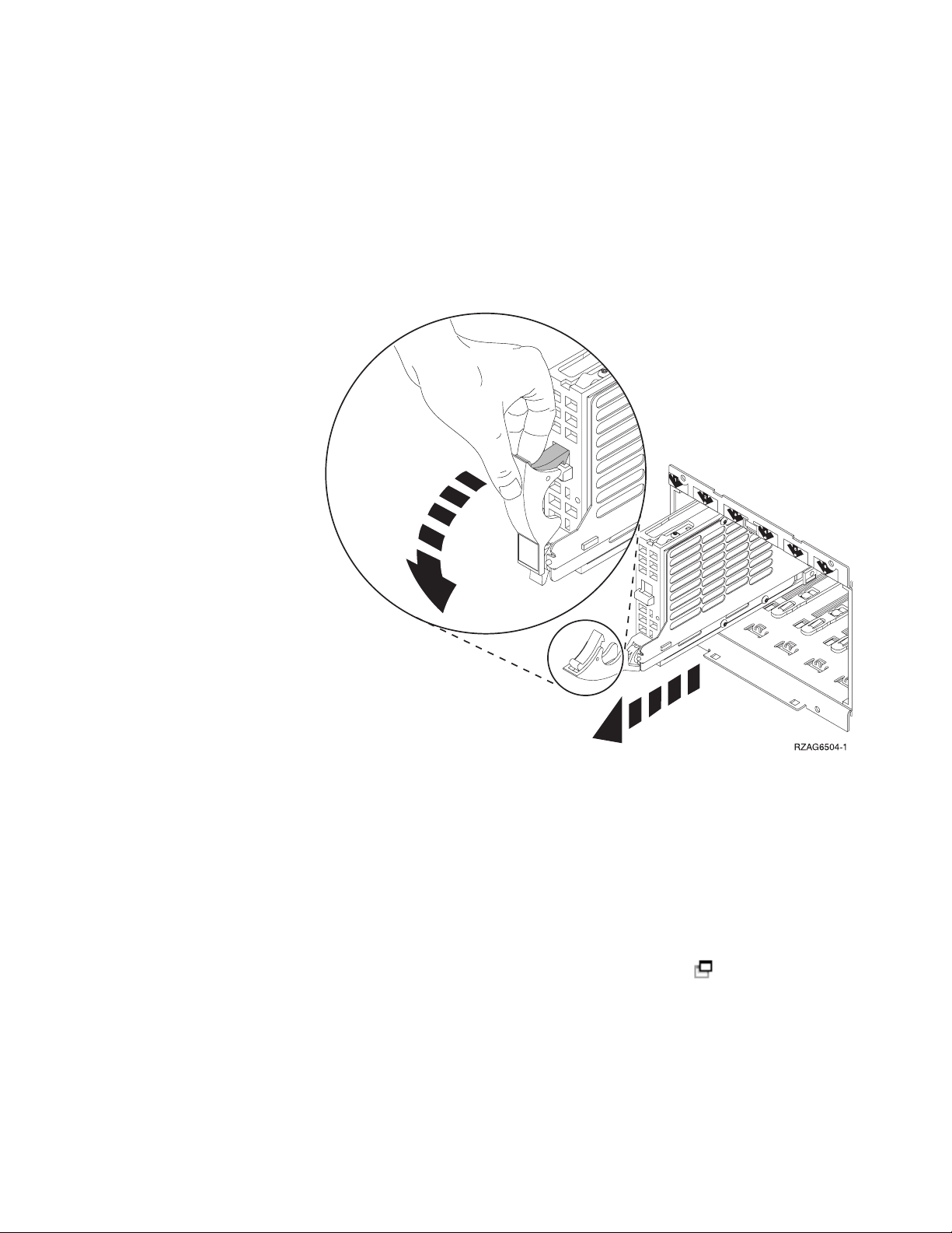
__ 15. When the light starts blinking, squeeze and pull the handle of the disk unit
out toward you before you remove the disk unit. If the handle is not all the
way out, the disk unit will not slide out of the system.
__ 16. Support the bottom of the disk unit assembly as you slide it completely
out. Do not hold the disk unit by the handle.
__ 17. The light will stop blinking and remain off when the disk unit is removed.
__ 18. Return to the console and wait until the Concurrent Maintenance Results
display appears.
Press F12.
__ 19. Find the package that contains the new disk unit assembly and remove it
from the static-protective package.
Attention: Disk units are fragile. Handle with care.
__ 20. Unlock the handle by squeezing and pulling it out toward you before you
install the disk unit. If the handle is not all the way out, the disk unit will
not slide into the system unit or the expansion unit. View video.
Chapter 2. Replace 43xx disk units 5
Page 12
__ 21. Support the bottom of the disk unit assembly as you slide it half way into
the system unit or the expansion unit. Do not push it any further.
Yo u install the disk units horizontally in the 7123, 7136, and 7137
Note:
disk unit enclosure.
__ 22. The physical locations you entered in step 11 on page 4 of this procedure
may still appear on the display. If not, retype the Physical Location (Frame
ID and position) where you will be installing the new disk unit.
In this example, Physical Location: Frame ID 1____ Position D06____ ,
you would install a disk unit in frame 1 (base system), disk unit position 6.
__ 23. Select option 2 (Install device) for the action to be performed.
__ 24. Set the time delay for one minute—01. Do not press Enter at this time.
Locate the light in the numbered arrow by the disk unit you are
Note:
replacing. When you press Enter, after a one minute delay, this light
comes on and begins to blink rapidly. You then have nine seconds to
slide the disk unit into place.
__ 25. Press Enter on the console.
__ 26. When the light starts blinking, slide the disk unit all the way in and then
lock it in place by closing the latch.
__ 27. The light stops blinking and remains on when you have installed the disk
unit properly.
__ 28. Return to the console and wait until the Concurrent Maintenance Results
display appears.
Press Enter.
__ 29. When the Hardware Service Manager display appears, press F3.
__ 30. Select Work with Disk Units on the System Service Tools display.
Press Enter.
6 43xx Disk Unit, 71xx Disk Expansion Unit, 71xx Disk Unit Enclosure V5R3
Page 13

__ 31. Select Work with disk unit recovery on the Work with Disk Units display.
Press Enter.
__ 32. Does the disk unit that you replaced have device parity protection
(RAID)?
__ No: The disk unit you replaced had mirrored protection. Go to step
33.
__ Yes: Follow these steps:
__ a. Select Rebuild disk unit data on the Work with Disk unit
recovery display.
Press Enter.
__ b. Select 1 to rebuild the disk unit displayed (disk unit displayed
is the disk unit that you removed) on the Rebuild Disk Unit
Data display.
Press Enter.
__ c. Press Enter on the Confirm Rebuild Disk Unit Data display. The
rebuild process may take several minutes to complete.
__ d. Install the disk unit covers. Align the tabs on the disk unit
cover with the slots in the system unit. Push the cover in until
it latches.
__ e. Install or close the system unit or expansion unit front cover.
__ f. Press F5 to refresh the display until the Percent complete
shows 5%.
__ g. When the display shows at least 5% complete, you can either
continue to monitor this display to completion, or press F3
(Exit) to return to the Work with disk units display.
__ h. Press F3 (Exit) to return to the System service tools display.
__ i. Press F3 (Exit) to return to the exit SST display and press Enter.
The replacement procedure is complete.
__ 33. The disk unit you replaced had mirrored protection. Follow these steps:
__ a. Select Replace configured unit on the Work with Disk unit recovery
display.
Press Enter.
__ b. Select the configured disk unit that you are exchanging (suspended
unit) on the Select Configured Unit to Replace display. There should be
only one unit available.
Press Enter.
__ c. Select the disk unit that you just installed on the Select Replacement
Unit display. This unit has a non-configured status.
In some cases, it may take several minutes for a new disk unit
Note:
to display. Repeat these steps until the new unit appears.
Press Enter.
__ d. Press Enter on the Confirm Replace of Configured Unit display to
confirm your choice for replacement.
The replacement process may take several minutes to complete.
When the process is complete, the Work with Disk unit recovery
display appears.
__ e. Press F3 (Exit) to return to the Work with disk units display.
__ f. Select Display disk configuration on the Work with disk units display.
Chapter 2. Replace 43xx disk units 7
Page 14

__ g. Select Display disk configuration status on the Display Disk
Configuration display.
Mirrored status will show Resuming. When complete, the Mirrored
status will show Active. This process may take several minutes to
complete. You can either monitor this display to completion, or press
F3 (Exit) repeatedly to return to the OS/400 main menu.
__ h. Install the disk unit covers. Align the tabs on the disk unit cover
with the slots in the system unit. Push the cover in until it latches.
__ i. Install or close the system unit or expansion unit front cover.
The replacement of the disk unit is complete.
Replace 43xx RAID or Mirrored protected disk units with system powered off
To replace a disk unit with the system powered off, follow these steps:
__ 1. For mirrored disk units, follow these steps to verify that the disk unit you
are replacing has been suspended before powering off the system:
__ a. Be sure you are signed on with at least service level authority.
__ b. Type strsst on the command line of the OS/400 session and press
Enter.
__ c. Type your service tools user ID and service tools password on
the Start Service Tools (STRSST) Sign On display. Press Enter.
The service tools password is case sensitive.
Note:
__ d. Select Work with disk units from the System Service Tools (SST)
display. Press Enter.
__ e. Select Display Disk Configuration from the Work with Disk Units
display. Press Enter.
__ f. Select Display Disk Configuration Status from the Display Disk
Configuration display. Press Enter.
__ g. Does the disk unit that is mirrored to the disk unit that you are
replacing (same unit number) have a status of Active?
__ No: Do NOT replace the disk unit. Contact IBM or your
authorized service provider.
__ Yes: Does the disk unit that you are replacing have a status of
Suspended?
__ Yes: Continue with the next step.
__ No: Follow these steps to suspend mirrored protection
on the disk unit that you are replacing:
1) Press F3 from the Display Disk Configuration display
to return to the Work with Disk Units display.
2) Select Work with Disk Unit Recovery from the Work
with Disk Units display. Press Enter.
3) Select Suspend mirrored protection from the Work
with Disk Unit Recovery display. Press Enter.
4) Select the option to Suspend the disk unit that you
are replacing from the Suspend Mirrored Protection
display. Press Enter.
2. Press F3 repeatedly to exit System Service Tools and return to the main
__
menu.
8 43xx Disk Unit, 71xx Disk Expansion Unit, 71xx Disk Unit Enclosure V5R3
Page 15

__ 3. Vary off the IXS:
__ a. Go to the Work with Configuration Status display by entering:
WRKCFGSTS at any command line. Press F4.
__ b. At the Work with Configuration Status display, enter *NWS at the Type
field and press Enter two times.
__ c. At the Work with Configuration Status display, select the Vary off
option in the Opt column next to the IXS and press Enter.
__ d. Press F12 to return to the Main Menu.
__ 4. “Power down the system unit” on page 67.
__ 5. If possible, use a wrist strap to prevent electrostatic discharge from
damaging your hardware. If you do not have a wrist strap, touch a metal
surface of the system or expansion unit before installing or replacing
hardware.
If you received the 2209 Disposable Wrist Strap, follow these steps:
__ a. Attach the disposable wrist strap. View video.
__ b. When you unroll the strap, remove the liner from the copper foil at
the end.
__ c. Attach the adhesive part of the copper foil to an exposed, unpainted
metal surface on the frame of the unit.
Follow the same precautions you would use without the wrist strap.
Note:
The 2209 Disposable Wrist Strap is for static control. It will not
increase or decrease your risk of receiving electric shock when using
or working on electrical equipment.
__ 6. Remove the disk unit covers. Squeeze the latch and pull out.
Note: iSeries 825 does not have disk unit covers.
__ 7. Locate the disk unit you want to replace.
__ 8. Unlock the handle by squeezing it and pulling it out toward you before
you remove the disk unit. If the handle is not all the way out, the disk unit
will not slide out of the system.
__ 9. Support the bottom of the disk unit assembly as you slide it completely
out. Do not hold the disk unit by the handle.
Chapter 2. Replace 43xx disk units 9
Page 16
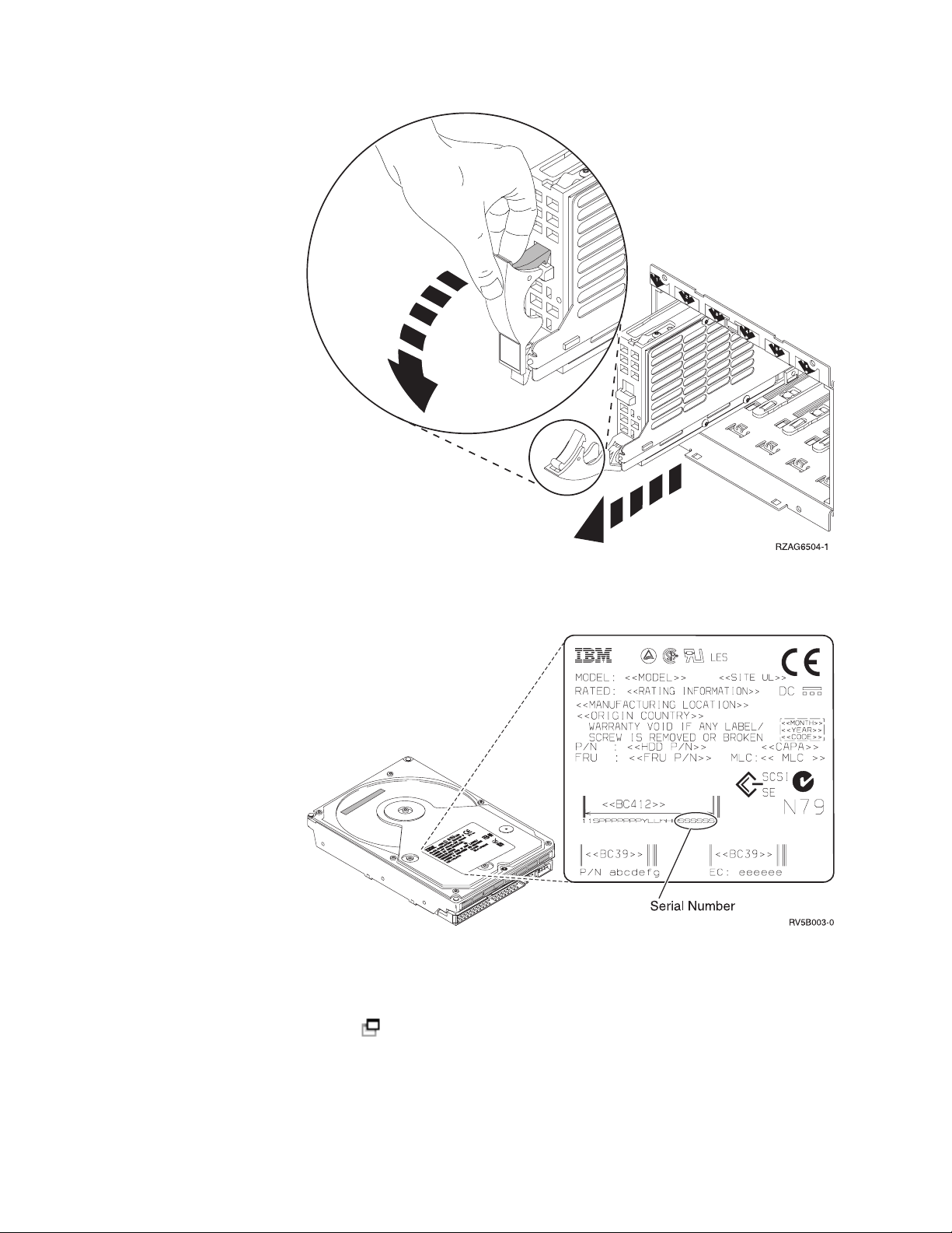
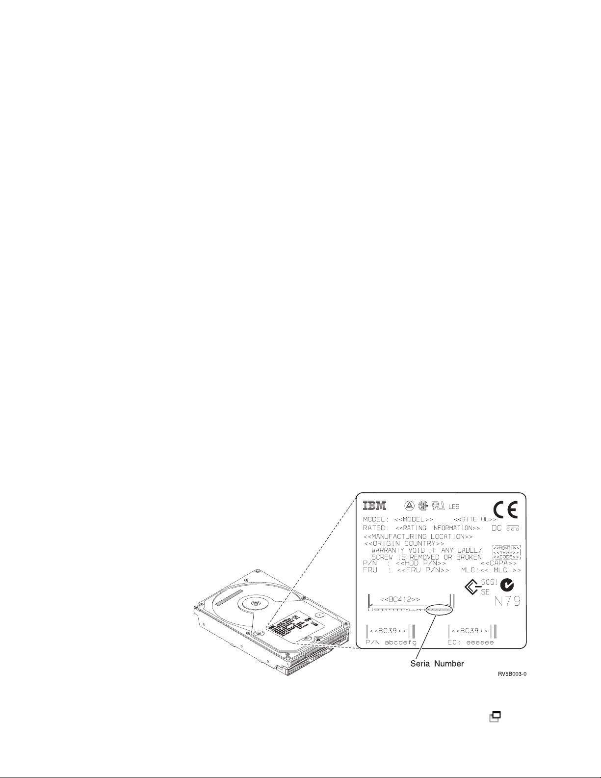
__ 10. Find the package that contains the new disk unit assembly and remove it
from the static-protective package. Write the serial number (use the last 4
digits) of the disk unit here ______________ before you install it.
Attention: Disk units are fragile. Handle with care.
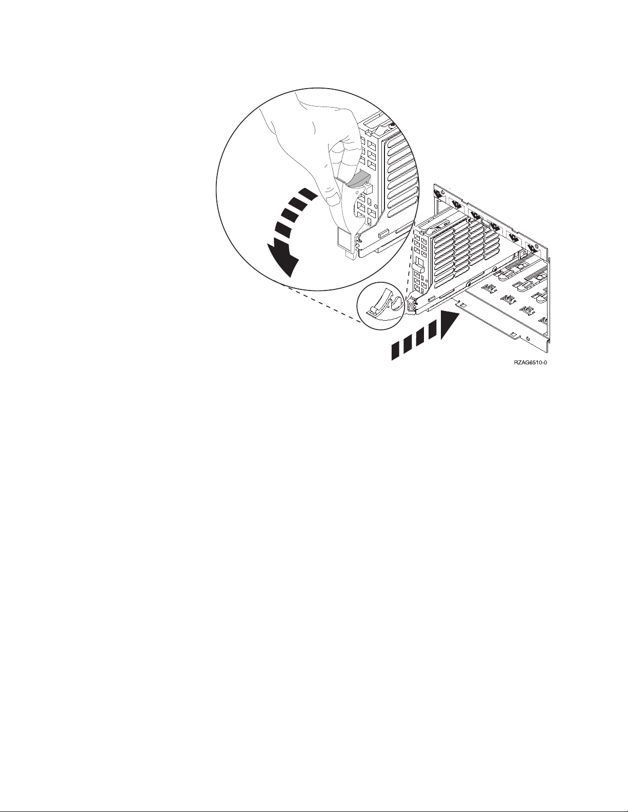
__ 11. Squeeze and pull the handle out toward you before you install the disk
unit. If the handle is not all the way out, the disk unit will not slide into
the system unit or the expansion unit. Do not hold the disk unit by the
handle. View video.
10 43xx Disk Unit, 71xx Disk Expansion Unit, 71xx Disk Unit Enclosure V5R3
Page 17

__ 12. Make sure that the disk unit handle is fully extended when sliding into the
system unit or the expansion unit. Support the bottom of the disk unit
assembly as you slide it into the system unit or the expansion unit until it
stops.
__ 13. Close the disk unit handle firmly locking it into place.
__ 14. Install the disk unit covers. Align the tabs on the disk unit enclosure cover
with the slots on the system unit enclosure. Push the cover in until it
latches.
__ 15. Install or close the unit front cover.
__ 16. DANGER
electrical outlet that is not correctly wired could place hazardous
An
voltage on metal parts of the system or the products that attach to the
system. It is the customer’s responsibility to ensure that the outlet is
correctly wired and grounded to prevent an electrical shock.
(RSFTD201)
Plug the following power cords into an electrical outlet.
v System unit
v System unit console
v Expansion units
__ 17. Plug in and power on all attached devices, such as printers and displays.
__ 18. If your system unit is an iSeries 270, 800, or 810, go to step 20.
__ 19. If your system unit is an iSeries 820, 825, 830, 840, 870 or 890, go to step 22
on page 12.
__ 20. Look at the Function/Data display on the control panel. Refer to
“System-unit control panel” on page 43.
__ 21. Does 01 B N V=S appear in the Function/Data display?
Chapter 2. Replace 43xx disk units 11
Page 18

__ Yes: Go to step 24.
__ No: Follow these steps:
__ a. Press the Increment/Decrement push button until 02 appears
in the Function/Data display.
__ b. Press the Enter push button on the control panel.
__ c. Press the Increment/Decrement push button until B appears in
the Function/Data display.
__ d. Press the Enter push button on the control panel.
__ e. Press the Increment/Decrement push button until N appears in
the Function/Data display.
__ f. Press the Enter push button on the control panel.
__ g. Press the Increment/Decrement push button until S appears in
the Function/Data display.
__ h. Press the Enter push button on the control panel.
__ i. Press the Increment/Decrement push button until 01 appears
in the Function/Data display.
__ j. Press the Enter push button on the control panel.
01 B N S should appear in the Function/Data display. If it does
not, repeat steps 21a through 21j.
__ k. Go to step 24.
__ 22. Look at the Function/Data display on the control panel.
__ 23. Does 01 B V=S appear in the Function/Data display and the Normal mode
indicator (OK) illuminated?
__ Yes: Continue with the next step.
__ No: Do the following:
__ a. Press the Mode Select button until the Normal mode indicator
(OK) lights up.
__ b. Press the Increment/Decrement push button until 02 appears
in the Function/Data display.
__ c. Press the Enter push button on the control panel.
__ d. Press the Increment/Decrement push button until B appears in
the Function/Data display.
__ e. Press the Enter push button on the control panel.
__ f. Press the Increment/Decrement push button until S appears in
the Function/Data display
__ g. Press the Enter push button on the control panel.
__ h. Press the Increment/Decrement push button until 01 appears
in the Function/Data display.
__ i. Press the Enter push button on the control panel.
01 B S should appear in the Function/Display panel. If it does
not appear, repeat steps 23a through 23i.
24. Press the Power push button that is located on the control panel. There is
__
approximately a 10-second delay before the power-on light comes on, and
data appears in the Function/Data display.
The system takes several minutes to power on and complete an IPL.
Note:
When the IPL is complete, the OS/400 signon display should appear
on your system unit console.
__ 25. Follow these steps to verify your disk unit configuration:
12 43xx Disk Unit, 71xx Disk Expansion Unit, 71xx Disk Unit Enclosure V5R3
Page 19

__ a. Type strsst on the command line of the iSeries session and press
Enter.
__ b. Select Work with disk units from the System Service Tools (SST)
display. Press Enter.
__ c. Select Work with disk unit recovery from the Work with Disk Units
display. Press Enter.
__ d. Does the disk unit that you replaced have device parity protection
(RAID)?
__ No: The disk unit you replaced had mirrored protection. Go
to step 26.
__ Yes: Follow these steps:
__ 1) Select Rebuild disk unit data on the Work with Disk
unit recovery display.
Press Enter.
__ 2) Select 1 to rebuild the disk unit displayed (disk unit
displayed is the disk unit that you removed) on the
Rebuild Disk Unit Data display.
Press Enter.
__ 3) Press Enter on the Confirm Rebuild Disk Unit Data
display. The rebuild process may take several minutes
to complete.
__ 4) Install the disk unit covers. Align the tabs on the disk
unit cover with the slots in the system unit. Push the
cover in until it latches.
__ 5) Install or close the system unit or expansion unit front
cover.
__ 6) Press F5 to refresh the display until the Percent
complete shows 5%.
__ 7) When the display shows at least 5% complete, you can
either continue to monitor this display to completion, or
press F3 (Exit) to return to the Work with disk units
display.
__ 8) Press F3 (Exit) to return to the System service tools
display.
__ 9) Press F3 (Exit) to return to the exit SST display and
press Enter.
The replacement procedure is complete.
26. The disk unit you replaced had mirrored protection. Follow these steps:
__
__ a. Select Replace configured unit on the Work with Disk unit recovery
display.
Press Enter.
__ b. Select the configured disk unit that you are exchanging (suspended
unit) on the Select Configured Unit to Replace display. There should be
only one unit available.
Press Enter.
__ c. Select the disk unit that you just installed on the Select Replacement
Unit display. This unit has a non-configured status.
In some cases, it may take several minutes for a new disk unit
Note:
to display. Repeat these steps until the new unit appears.
Chapter 2. Replace 43xx disk units 13
Page 20

Press Enter.
__ d. Press Enter on the Confirm Replace of Configured Unit display to
confirm your choice for replacement.
The replacement process may take several minutes to complete.
When the process is complete, the Work with Disk unit recovery
display appears.
__ e. Press F3 (Exit) to return to the Work with disk units display.
__ f. Select Display disk configuration on the Work with disk units display.
__ g. Select Display disk configuration status on the Display Disk
Configuration display.
Mirrored status will show Resuming. When complete, the Mirrored
status will show Active. This process may take several minutes to
complete. You can either monitor this display to completion, or press
F3 (Exit) repeatedly to return to the OS/400 main menu.
__ h. Install the disk unit covers. Align the tabs on the disk unit cover
with the slots in the system unit. Push the cover in until it latches.
__ i. Install or close the system unit or expansion unit front cover.
The replacement of the disk unit is complete.
14 43xx Disk Unit, 71xx Disk Expansion Unit, 71xx Disk Unit Enclosure V5R3
Page 21

Chapter 3. Install 43xx disk units
To install a 43xx disk unit; follow these steps:
Note: The figures in these instructions may not look exactly like the server that
you have. However, the steps to perform the task are the same.
__ 1. Perform prerequisite tasks as described in “Before you begin” on page 1.
__ 2. “Open or remove the front cover” on page 29.
Your system or expansion unit can either be powered off (nonconcurrent) or
powered on (concurrent) when you install the disk units.
Select the preferred procedure from the following:
v “Install 43xx disk units with system power on” on page 15
v “Install 43xx disk units with system power off” on page 20
Install 43xx disk units with system power on
Be sure you understand the complexity of the powered on (concurrent) procedure
before you begin. If you do not feel comfortable using the concurrent procedure,
go to “Install 43xx disk units with system power off” on page 20.
To perform the concurrent installation, follow these steps:
__ 1. If possible, use a wrist strap to prevent electrostatic discharge from
damaging your hardware. If you do not have a wrist strap, touch a metal
surface of the system or expansion unit before installing or replacing
hardware.
If you received the 2209 Disposable Wrist Strap, follow these steps:
__ a. Attach the disposable wrist strap. View video.
__ b. When you unroll the strap, remove the liner from the copper foil at
the end.
__ c. Attach the adhesive part of the copper foil to an exposed, unpainted
metal surface on the frame of the unit.
Follow the same precautions you would use without the wrist strap.
Note:
The 2209 Disposable Wrist Strap is for static control. It will not
increase or decrease your risk of receiving electric shock when using
or working on electrical equipment.
__ 2. Find the “Disk unit locations” on page 33 in your system unit or your
expansion unit.
__ 3. Remove the disk unit covers. Squeeze the latch and pull out.
Note: iSeries 825 does not have disk unit covers.
__ 4. Look at the front of the system unit or the expansion unit and determine the
next available position. When you have a system unit with an expansion
unit, fill the slot positions in the system unit first. If using logical
partitions, go to Plan for logical partitions, in the Information Center, for
specific load source disk unit locations.
© Copyright IBM Corp. 2000, 2005 15
Page 22
__ 5. Follow the steps in “Details: Install 43xx disk units with system power on”
to install the new disk unit.
Details: Install 43xx disk units with system power on
__ 1. Write down the position where the new disk will be installed
________________ (for example; D03).
__ 2. Write down the Frame ID where you will be installing the disk unit here
____________________ . You will need it later. The base system Frame ID is
1. The Frame ID for each external expansion unit is displayed on the front
display (for example: 02)
__ 3. Be sure you are signed on with at least service level authority.
__ 4. Type strsst on the command line of the iSeries session and press Enter.
__ 5. Type your service tools user ID and service tools password on the
System Service Tools (SST) Sign On display. Press Enter.
__ 6. Select Start a service tool from the System Service Tools (SST) display. Press
Enter.
__ 7. Select Hardware service manager from the Start a Service Tool display. Press
Enter.
__ 8. Select Device Concurrent Maintenance from the Hardware Service Manager
display. Press Enter.
__ 9. Type the Physical Location (Frame ID and position) where you will be
installing the new disk unit. Refer to the locations you recorded in step 1
and step 2 of this procedure.
In this example, Physical Location: Frame ID 1____ Position D06____ ,
you would install a disk unit in frame 1 (base system), disk unit position 6.
__ 10. Select option 2 (Install device for the action to be performed.)
__ 11. Set the time delay for one minute—01. Do not press Enter at this time.
__ 12. Find the package that contains the new disk unit assembly and remove it
from the static-protective package.
Attention: Disk units are fragile. Handle with care.
Write the serial number (use the last four digits) of the disk unit here
______________ before you install it.
__ 13. Unlock the handle by squeezing and pulling it out toward you and down
before you install the disk unit. If the handle is not all the way down, the
disk unit will not slide into the system unit or the expansion unit. View
16 43xx Disk Unit, 71xx Disk Expansion Unit, 71xx Disk Unit Enclosure V5R3
Page 23
video.
__ 14. Support the disk unit assembly as you slide it half way into the system
unit or the expansion unit. Do not push it any further.
Yo u install the disk units horizontally in the 7123, 7136, and 7137
Note:
disk unit enclosure.
__ 15. Locate the light in the numbered arrow by the disk unit you are installing.
When you press Enter, after a one minute delay, the light comes on and
begins to blink rapidly. You then have nine seconds to slide the disk unit
all the way forward and push in the handle on the disk unit.
__ 16. Press Enter on the console.
__ 17. When the light starts blinking, slide the disk unit all the way in and lock it
in place by closing the latch.
__ 18. The light stops blinking and remains on when you have installed the disk
unit properly.
__ 19. Return to the console and wait until the Concurrent Maintenance Results
display appears.
Press Enter.
__ 20. Do you have another disk unit to install?
__ No: Continue with the next step.
__ Yes: Look at the front of the system unit or the expansion unit and
determine the next available position. Repeat steps 8 on page 16
through 19 to install the next disk unit.
21. When the Hardware Service Manager display appears, press F12.
__
__ 22. Select Work with Disk Units on the System Service Tools display.
Press Enter.
__ 23. Select Display disk configuration on the Work with Disk Units display.
Chapter 3. Install 43xx disk units 17
Page 24

Press Enter.
__ 24. Select Display non-configured units on the Display disk configuration
display.
Press Enter.
__ 25. The disk unit that you installed should be listed. The serial number should
match the serial number you wrote in step 12 on page 16.
The new disk unit may take up to five minutes to appear in the list.
Note:
If the disk unit is not listed, ensure that the disk unit was properly
installed. Repeat steps “Install 43xx disk units with system power
on” on page 15 through 19 on page 17.
__ 26. Press F12, twice.
__ 27. Select Work with disk configuration on the Work with Disk Units display.
Press Enter.
__ 28. Are you adding a disk unit to an existing device parity set? If you need
more information about device parity, go to Backup and Recovery
.
__ Yes: Continue with the next step.
__ No: Do you want to start a device parity set?
__ Yes: Go to Device parity protection in the Information Center.
__ No: Go to step 46 on page 19.
29. Select Include unit in device parity protection on the Work with disk
__
configuration display.
Press Enter.
__ 30. Did the Include Device Parity Protection Failed display appear?
__ Yes: Continue with the next step.
__ No: Go to step 34.
31. The following conditions must be met before you can start device parity
__
protection. Including the disk unit in device parity protection may fail for
one or more reasons.
v If there are enough disk units available to create a new parity set, the
units will be eligible for Start Device Parity Protection operation and not
for the Include Device Parity Protection operation. For more information,
go to Backup and Recovery
.
v All disk units in a parity set must be the same capacity with a
minimum number of 3 or 4 disk units and maximum of 10 or 18 units
in the resulting parity set, depending on the disk unit type.
v Not all disk units attached to an advanced function input/output
processor have reported to the system. Retry the operation.
v The type/model of the disk units must be supported for the requested
operation.
32. When the above conditions are met, select F12 to return to the Work with
__
disk configuration display.
__ 33. Select Include unit in device parity protection on the Work with disk
configuration display.
Press Enter.
__ 34. Select the disk units to include in Device Parity Protection. Type a 1 in the
Option column on the Include Disk Units in Device Parity Protection display.
Press Enter.
18 43xx Disk Unit, 71xx Disk Expansion Unit, 71xx Disk Unit Enclosure V5R3
Page 25

__ 35. Press Enter to confirm your choice. The configuration will start and may
take 30 to 60 minutes to complete.
__ 36. When the device parity protection is complete, the message Selected units
have been included successfully appears on the Work with disk
configuration display.
__ 37. Select Display disk configuration on the Work with disk configuration
display and press Enter.
__ 38. Select Display disk configuration status on the Display disk configuration
display and press Enter.
__ 39. If you have more than one ASP, determine the auxiliary storage pool (ASP)
to which you want to add the disk units.
__ 40. Press F12, twice.
__ 41. Select Add units to the ASPs and balance data on the Work with disk
configuration display.
Press Enter.
__ 42. Specify the ASP that you determined in step 39 on the Specify ASPs to
Add Units to display.
Press Enter.
__ 43. The Confirm Add Units display appears showing the configuration your
system will have when the add operation completes.
If you have selected the wrong ASP, press F12 to change your
Note:
options.
the Enter key to continue. The add process will take several minutes
Press
to complete.
__ 44. When the message Selected units have been added successfully
appears, return to the Main Menu. (Press F3 three times and press Enter.)
__ 45. Go to step 54 on page 20.
__ 46. Select Display disk configuration on the Work with Disk Configuration
display.
Press Enter.
__ 47. Select Display disk configuration status on the Display Disk Configuration
display.
Press Enter.
__ 48. If you have more than one ASP, determine the auxiliary storage pool (ASP)
to which you want to add the disk units.
__ 49. Press F12, twice.
__ 50. Select Add units to ASPs on the Work with Disk Configuration display.
Press Enter.
__ 51. Specify the number of the ASP to which you want to add the disk unit.
The system ASP is ASP 1.
Press Enter.
Notes:
a. When an even number of disk units are added to a mirrored ASP, they
will automatically become mirrored protected.
b. If ASP is mirror protected, disk units must be added in pairs.
52. The Confirm Add Units display appears showing the configuration your
__
system will have when the add operation completes.
Chapter 3. Install 43xx disk units 19
Page 26

Note: If you have selected the wrong ASP, press F12 to change your
options.
the Enter key to continue. The add process will take several minutes
Press
to complete.
__ 53. When the message Selected units have been added successfully
appears, return to the Main Menu. (Press F3 three times and press Enter.)
__ 54. Install the disk unit covers. Align the tabs on the disk unit cover with the
slots in the system unit. Push the cover in until it latches.
__ 55. Install or close the system unit or expansion unit front cover.
__ 56. If you have a printer, print the configuration list. A service representative
may refer to the configuration list in the future.
__ a. You need to sign on with service authority.
__ b. Type strsst on the Main Menu command line and press Enter.
__ c. Type your service tools user ID and service tools password on
the System Service Tools (SST) Sign On display and press Enter.
__ d. Select Start a service tool on the System Service Tools (SST) display
and press Enter.
__ e. Select Hardware service manager on the Start a Service Tool display
and press Enter.
__ f. Press F6 (Print configuration) from the Hardware Service Manager
display.
__ g. Press F3 (Exit) twice to return to the Main Menu and press Enter.
__ h. Place the configuration list where you can reference it in the future.
57. The installation of the disk unit is complete.
__
__ 58. For information on disk unit configuration, go to the Disk management
topic in the Information Center.
Install 43xx disk units with system power off
To perform the nonconcurrent installation, follow these steps:
__ 1. If you haven’t done so, power down the system. For instructions, refer to
“Power down the system unit” on page 67.
__ 2. If possible, use a wrist strap to prevent electrostatic discharge from
damaging your hardware. If you do not have a wrist strap, touch a metal
surface of the system or expansion unit before installing or replacing
hardware.
If you received the 2209 Disposable Wrist Strap, follow these steps:
__ a. Attach the disposable wrist strap. View video.
__ b. When you unroll the strap, remove the liner from the copper foil at
the end.
__ c. Attach the adhesive part of the copper foil to an exposed, unpainted
metal surface on the frame of the unit.
Follow the same precautions you would use without the wrist strap.
Note:
The 2209 Disposable Wrist Strap is for static control. It will not
increase or decrease your risk of receiving electric shock when using
or working on electrical equipment.
__ 3. Find the “Disk unit locations” on page 33 in your system unit or your
expansion unit.
__ 4. Remove the disk unit covers. Squeeze the latch and pull out.
20 43xx Disk Unit, 71xx Disk Expansion Unit, 71xx Disk Unit Enclosure V5R3
Page 27

Note: iSeries 825 does not use disk unit covers.
__ 5. Look at the front of the system unit or the expansion unit and determine the
next available position. When you have a system unit with an expansion
unit, fill the slot positions sequentially in the system unit first. If using
logical partitions, go to Plan for logical partitions, in the Information Center,
for specific load source disk unit locations.
__ 6. Follow the steps in “Details: Install 43xx disk units with system power off”
to install the new disk unit.
Details: Install 43xx disk units with system power off
Attention: Disk units are fragile. Handle with care.
__ 1. Find the package that contains the new disk unit assembly and remove it
from the static-protective package. Write the serial number (use the last 4
digits) of the disk unit here ______________ before you install it.
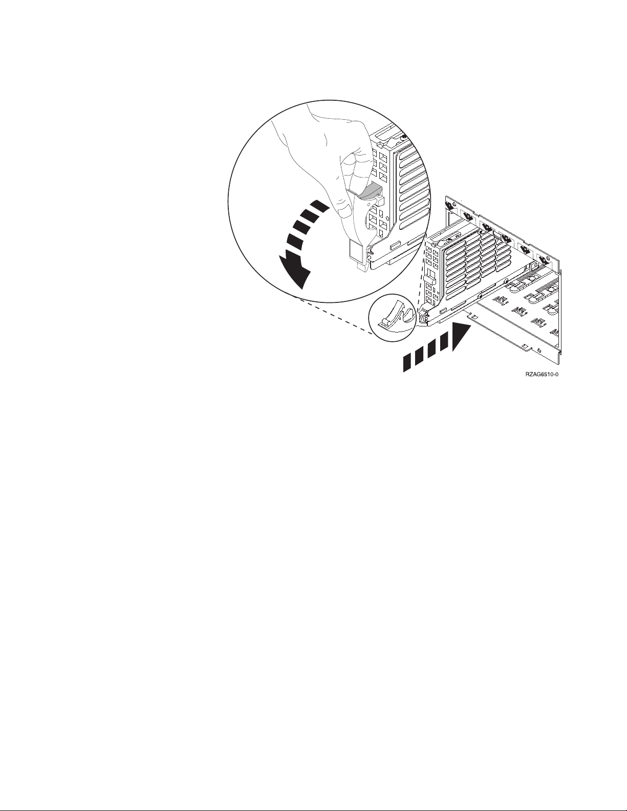
__ 2. Squeeze and pull the handle out toward you and down before you install
the disk unit. If the handle is not all the way down, the disk unit will not
slide into the system unit or the expansion unit. View video.
Chapter 3. Install 43xx disk units 21
Page 28

__ 3. Support the bottom of the disk unit assembly as you slide it completely
forward and install it into the system unit or the expansion unit. Do not
hold the disk unit by the handle.
__ 4. Align the disk unit assembly with the next available slot and slide it into
the system or expansion unit until it stops. Make sure that the handle is
fully extended when sliding into the system unit or the expansion unit.
__ 5. Close the disk unit handle firmly locking it into place.
__ 6. Do you have another disk unit to install?
__ No: Continue with the next step.
__ Yes: Repeat this procedure to install the next disk unit.
__ 7. Install the disk unit covers. Align the tabs on the disk unit enclosure cover
with the slots on the system unit enclosure. Push the cover in until it
latches.
__ 8. Do you have any other adapter cards or devices to install?
__ No: Continue with the next step.
__ Yes: If you have another device such as an adapter card, a tape unit,
or a memory card to install, go to the instructions that came with
that device.
9. Remove the disposable wrist strap.
__
__ 10. Install or close the unit front cover.
22 43xx Disk Unit, 71xx Disk Expansion Unit, 71xx Disk Unit Enclosure V5R3
Page 29

__ 11. DANGER
electrical outlet that is not correctly wired could place hazardous
An
voltage on metal parts of the system or the products that attach to the
system. It is the customer’s responsibility to ensure that the outlet is
correctly wired and grounded to prevent an electrical shock.
(RSFTD201)
Plug the following power cords into an electrical outlet.
v System unit
v System unit console
v Expansion units
__ 12. Plug in and power on all attached devices, such as printers and displays.
__ 13. If your system unit is an iSeries 270, 800, or 810, go to step 15.
__ 14. If your system unit is an iSeries 820, 825, 830, 840, 870 or 890, go to step 18
on page 24.
__ 15. Look at the Function/Data display on the control panel. Refer to
“System-unit control panel” on page 43.
__ 16. Did you just install a 7104 or 7116 Expansion Unit?
__ No: Continue with the next step.
__ Yes: Do the following:
__ a. Press the Increment/Decrement push button until 02 appears
in the Function/Data display.
__ b. Press the Enter push button on the control panel.
__ c. Press the Increment/Decrement push button until B appears in
the Function/Data display.
__ d. Press the Enter push button on the control panel.
__ e. Press the Increment/Decrement push button until M appears in
the Function/Data display.
__ f. Press the Enter push button on the control panel.
__ g. Press the Increment/Decrement push button until S appears in
the Function/Data display.
__ h. Press the Enter push button on the control panel.
__ i. Press the Increment/Decrement push button until 07 appears
in the Function/Data display.
__ j. Press the Enter push button on the control panel.
__ k. Press the Increment/Decrement push button until 07A9
appears in the Function/Data display.
__ l. Press the Enter push button on the control panel.
__ m. Press the Increment/Decrement push button until 0701
appears in the Function/Data display.
__ n. Press the Enter push button on the control panel.
__ o. Depending on the processor type you identified in step 1 on
page 45, the configuration ID in step 16p will be 0795 or 0796.
__ 2248, 2250, or 2422 processors: 0795
__ For all other processors: 0796
p. Press the Increment/Decrement push button until 0795 or
__
0796 appears in the Function/Data display.
__ q. Press the Enter push button on the control panel.
Chapter 3. Install 43xx disk units 23
Page 30

01 B M V=F should appear in the Function/Data display. If it
does not, repeat steps 16a on page 23 through 16q on page 23.
__ r. Go to step 20.
17. Does 01 B M V=S appear in the Function/Data display?
__
__ Yes: Go to step 20.
__ No: Do the following:
__ a. Press the Increment/Decrement push button until 02 appears
in the Function/Data display.
__ b. Press the Enter push button on the control panel.
__ c. Press the Increment/Decrement push button until B appears in
the Function/Data display.
__ d. Press the Enter push button on the control panel.
__ e. Press the Increment/Decrement push button until M appears in
the Function/Data display.
__ f. Press the Enter push button on the control panel.
__ g. Press the Increment/Decrement push button until S appears in
the Function/Data display.
__ h. Press the Enter push button on the control panel.
__ i. Press the Increment/Decrement push button until 01 appears
in the Function/Data display.
__ j. Press the Enter push button on the control panel.
01 B M S should appear in the Function/Data display. If it does
not, repeat steps 17a through 17j.
__ k. Go to step 20.
18. Look at the Function/Data display on the control panel.
__
__ 19. Does 01 B V=S appear in the Function/Data display and the Manual mode
indicator (a small hand) illuminated?
__ Yes: Continue with the next step.
__ No: Do the following:
__ a. Press the Mode Select button until the Manual mode indicator
(a small hand) lights up.
__ b. Press the Increment/Decrement push button until 02 appears
in the Function/Data display.
__ c. Press the Enter push button on the control panel.
__ d. Press the Increment/Decrement push button until B appears in
the Function/Data display.
__ e. Press the Enter push button on the control panel.
__ f. Press the Increment/Decrement push button until S appears in
the Function/Data display
__ g. Press the Enter push button on the control panel.
__ h. Press the Increment/Decrement push button until 01 appears
in the Function/Data display.
__ i. Press the Enter push button on the control panel.
01 B S should appear in the Function/Display panel. If it does
not appear, repeat steps 19a through 19i.
20. Press the Power push button that is located on the iSeries control panel.
__
There is approximately a 10-second delay before the power-on light comes
on, and data appears in the Function/Data display.
24 43xx Disk Unit, 71xx Disk Expansion Unit, 71xx Disk Unit Enclosure V5R3
Page 31

Note: The system takes approximately 5 to 10 minutes to power on and
complete an IPL. When the IPL is complete, the IPL or Install the
System display should appear on your system unit console.
__ 21. Do the following to verify your disk unit configuration:
__ a. Select Use Dedicated Service Tools (DST) when the IPL or Install the
System display appears.
Press Enter.
__ b. Enter your DST user ID and password.
Press Enter.
__ c. Select Work with disk units on the Use Dedicated Service Tools (DST)
display.
Press Enter.
__ d. Select Work with disk configuration on the Work with Disk Units
display.
Press Enter.
__ e. Select Display disk configuration on the Work with Disk
Configuration display.
Press Enter.
__ f. Select Display non-configured units on the Display Disk Configuration
display.
Press Enter.
__ g. The disk units that you installed should be listed. The serial number
should match the serial number you wrote in step 1 on page 21.
If the disk unit is not listed, ensure that the disk unit is
Note:
properly installed.
__ h. Return to the Work with Disk Configuration display (press F12 two
times).
22. Are you adding a disk unit to an existing device parity set? If you need
__
more information about device parity, refer to Backup and Recovery
__ Yes: Continue with the next step.
__ No: Do you want to start a device parity set?
__ Yes: Go to Device parity protection in the Information Center.
__ No: Go to step 41 on page 26.
23. Select Work with device parity protection on the Work with Disk
__
Configuration display.
Press Enter.
__ 24. Select Include unit in device parity protection on the Work with Device
Parity Protection display.
Press Enter.
__ 25. Did the Include Device Parity Protection Failed display appear?
__ Yes: Continue with the next step.
__ No: Go to step 28 on page 26.
26. The following conditions must be met before you can start device parity
__
protection. Including the disk unit in device parity protection may fail for
one or more reasons.
v If there are enough disk units available to create a new parity set, the
units will be eligible for Start Device Parity Protection operation and
.
Chapter 3. Install 43xx disk units 25
Page 32

not for the Include Device Parity Protection operation. For more
information, refer to Backup and Recovery
.
v All disk units in a parity set must be the same capacity with a
minimum number of three or four disk units and maximum of 10 or
18 units in the resulting parity set, depending on the disk unit type.
v Not all disk units attached to an advanced function input/output
processor have reported to the system. Retry the operation.
v The type/model of the disk units is not supported for the requested
operation.
27. When the above conditions are met, press F12 twice to return to the Work
__
with Disk Configuration display.
__ 28. On the Include Disk Units in Device Parity Protection display, select the disk
units to be included in Device Parity Protection. Type a 1 in the Option
column.
Press Enter.
__ 29. Press Enter to confirm your choice. The configuration will start and may
take 30 to 60 minutes to complete.
__ 30. When the device parity protection is complete, the message “Selected units
have been included successfully” appears on the Work with device parity
protection display.
Press F12.
__ 31. Select Display disk configuration on the Work with disk configuration
display.
Press Enter.
__ 32. Select Display disk configuration status on the Display disk configuration
display.
__ 33. If you have more than one ASP, determine the auxiliary storage pool (ASP)
to which you want to add the disk unit.
__ 34. Press F12, twice.
__ 35. Select Work with ASP configuration on the Work with disk configuration
display.
Press Enter.
__ 36. Select Add units to ASPs on the Work with ASP configuration display.
Press Enter.
__ 37. Specify the ASP you determined in step 33 on the Specify ASPs to Add Units
to display.
Press Enter.
__ 38. Press Enter to confirm.
__ 39. When the message “Selected units have been added successfully” appears,
press F3 three times and press Enter to return to the Main Menu.
__ 40. Go to step 45 on page 27.
__ 41. Select Work with ASP configuration on the Work with Disk Configuration
display and press Enter.
__ 42. Select Add units to ASPs on the Work with ASP configuration display.
Press Enter.
__ 43. Specify the number of the ASP to which you want to add the disk unit.
The system ASP is ASP 1.
Press Enter.
26 43xx Disk Unit, 71xx Disk Expansion Unit, 71xx Disk Unit Enclosure V5R3
Page 33

Notes:
a. When an even number of disk units are added to a mirrored ASP, they
will automatically become mirrored protected.
b. If ASP is mirror protected, disk units must be added in pairs.
__ 44. The Confirm Add Units display appears showing the configuration your
system will have when the add operation completes.
If you have selected the wrong ASP, press F12 to change your
Note:
options.
the Enter key to continue. The add process will take several minutes
Press
to complete.
__ 45. Press F12 three times to return to the Use Dedicated Service Tools (DST)
display.
__ 46. Select Perform an IPL on the Use Dedicated Service Tools (DST) display.
Press Enter.
__ 47. If you have a printer, print the configuration list. A service representative
may refer to the configuration list in the future.
__ a. You need to sign on with service authority.
__ b. Type strsst on the Main Menu command line.
Press Enter.
__ c. Type your service tools user ID and service tools password on
the System Service Tools (SST) Sign On display.
Press Enter.
__ d. Select Start a service tool on the System Service Tools (SST) display.
Press Enter.
__ e. Select Hardware service manager on the Start a Service Tool display.
Press Enter.
__ f. Press F6 (print the configuration) from the Hardware Service Manager
display.
__ g. To return to the Main Menu, press F3 (Exit) twice and then press
Enter.
__ h. Place the configuration list where you can refer to it in the future.
48. The installation of the disk unit is complete.
__
__ 49. For information on how to make your disk unit operational, go to the Disk
management topic in the Information Center.
Chapter 3. Install 43xx disk units 27
Page 34

28 43xx Disk Unit, 71xx Disk Expansion Unit, 71xx Disk Unit Enclosure V5R3
Page 35

Open or remove the front cover
Select your unit:
v “270, 800, 810, 820, or 5075 front cover” on page 29
v “270, 800, or 810 in a rack” on page 31
v “825 front cover” on page 30
v “830, 840, 870, 890, 5074, 5079, 5094 or 5095” on page 32
270, 800, 810, 820, or 5075 front cover
Remove the system unit or expansion unit front cover by gripping the sides of the
cover A and pulling the cover toward you. View video.
© Copyright IBM Corp. 2000, 2005 29
Page 36

825 front cover
Remove the front cover by gripping the sides of the cover and pulling the cover
toward you. View video.
30 43xx Disk Unit, 71xx Disk Expansion Unit, 71xx Disk Unit Enclosure V5R3
Page 37

270, 800, or 810 in a rack
Open or remove the front cover 31
Page 38

830, 840, 870, 890, 5074, 5079, 5094 or 5095
Use A to open the front cover. If needed, use latch B to remove the front cover.
32 43xx Disk Unit, 71xx Disk Expansion Unit, 71xx Disk Unit Enclosure V5R3
Page 39

Disk unit locations
Locate your system or expansion unit to find the disk unit locations. If using
logical partitions, go to Plan for logical partitions, in the Information Center, for
specific load source disk unit locations.
v “270, 800, or 810 system unit” on page 33
v “7104 or 7116 expansion unit” on page 34
v “820 system unit” on page 35
v “825 system unit” on page 36
v “830 system unit” on page 37
v “840 system unit” on page 38
v “870 and 890 system unit” on page 38
v “5065, 5074, and 5094 expansion unit” on page 39
v “5075 and 5095 expansion unit” on page 40
v “5079 and 5294 expansion unit” on page 41
270, 800, or 810 system unit
© Copyright IBM Corp. 2000, 2005 33
Page 40

7104 or 7116 expansion unit
34 43xx Disk Unit, 71xx Disk Expansion Unit, 71xx Disk Unit Enclosure V5R3
Page 41

820 system unit
Disk unit locations 35
Page 42

825 system unit
36 43xx Disk Unit, 71xx Disk Expansion Unit, 71xx Disk Unit Enclosure V5R3
Page 43

830 system unit
Note: Disk unit plug sequence for optimum performance: D31, D36, D46, D32,
D37, D47, ... D50, (add second adaptor), D01, D11, D21, D02, ... D25, (add
third adaptor), D06, D16, D26, D07, ... D30.
Disk unit locations 37
Page 44

840 system unit
Note: Disk unit plug sequence for optimum performance: D31, D36, D46, D32,
D37, D47, ... D50, (add second adaptor), D01, D11, D21, D02, ... D25, (add
third adaptor), D06, D16, D26, D07, ... D30.
870 and 890 system unit
38 43xx Disk Unit, 71xx Disk Expansion Unit, 71xx Disk Unit Enclosure V5R3
Page 45

Note: Disk unit plug sequence for optimum performance: D31, D36, D46, D32,
D37, D47, ... D50, (add second adaptor), D01, D11, D21, D02, ... D25, (add
third adaptor), D06, D16, D26, D07, ... D30.
5065, 5074, and 5094 expansion unit
Select the optimal disk unit position
When you install disk units, you should evenly distribute the disk units on the
disk controllers. Evenly distributing the disk units will optimize them for
maximum performance.
Note for 5079 users: The 5079 consists of two independent expansion units:
5079–001 and 5079–002. Installation rules and procedures
apply to each expansion unit independently.
for 5094 users: The 5094 consists of two independent expansion units:
Note
5094–001 and 5094–002. Installation rules and procedures
apply to each expansion unit independently.
If you are installing feature 4331 1.65 GB Read Cache, solid-state disk units,
Note:
you can only install them in position one of your disk unit enclosures. You
can install three of these features (if you have three disk unit controllers) in
the expansion unit, for example, in positions D31, D01, and D06.
Refer to the label on the inside of the front cover and install the disk units in this
order:
__ 1. First fill all the disk unit positions that are controlled by the first high-speed
disk-unit controller.
__ a. Fill the slot 1’s: D31, D36, D46
__ b. Fill the slot 2’s D32, D37, D47
Disk unit locations 39
Page 46

__ c. Fill the slot 3’s: D33, D38, D48
__ d. Fill the slot 4’s: D34, D39, D49
__ e. Fill the slot 5’s: D35, D40, D50
__ 2. Your expansion unit requires a second high-speed disk-unit controller before
you can install disk units into the following positions. Contact IBM or an
authorized dealer if your expansion unit does not have a second high-speed
disk-unit controller (IOA Card 2).
Next fill the positions in (IOA Card 2) this sequence:
__ a. Fill the slot 1’s: D01, D11, D21
__ b. Fill the slot 2’s: D02, D12, D22
__ c. Fill the slot 3’s: D03, D13, D23
__ d. Fill the slot 4’s: D04, D14, D24
__ e. Fill the slot 5’s: D05, D15, D25
3. Your expansion unit requires a third high-speed disk-unit controller before
__
you can install disk units into the following positions. Contact IBM or an
authorized dealer if your expansion unit does not have a third high-speed
disk-unit controller (IOA Card 3).
Last fill the positions in (IOA Card 3) this sequence:
__ a. Fill the slot 1’s: D06, D16, D26
__ b. Fill the slot 2’s: D07, D17, D27
__ c. Fill the slot 3’s: D08, D18, D28
__ d. Fill the slot 4’s: D09, D19, D29
__ e. Fill the slot 5’s: D10, D20, D30
5075 and 5095 expansion unit
40 43xx Disk Unit, 71xx Disk Expansion Unit, 71xx Disk Unit Enclosure V5R3
Page 47

5079 and 5294 expansion unit
Select the optimal disk unit position
When you install disk units, you should evenly distributing the disk units on the
disk controllers. Evenly distributing the disk units will optimize them for
maximum performance.
Note for 5079 users: The 5079 consists of two independent expansion units:
5079–001 and 5079–002. Installation rules and procedures
apply to each expansion unit independently.
Disk unit locations 41
Page 48

Note for 5294 users: The 5294 consists of two independent expansion units:
5294–001 and 5294–002. Installation rules and procedures
apply to each expansion unit independently.
If you are installing feature 4331 1.65 GB Read Cache, solid-state disk units,
Note:
you can only install them in position one of your disk unit enclosures. You
can install three of these features (if you have three disk unit controllers) in
the expansion unit, for example, in positions D31, D01, and D06.
Refer to the label on the inside of the front cover and install the disk units in this
order:
__ 1. First fill all the disk unit positions that are controlled by the first high-speed
disk-unit controller.
__ a. Fill the slot 1’s: D31, D36, D46
__ b. Fill the slot 2’s D32, D37, D47
__ c. Fill the slot 3’s: D33, D38, D48
__ d. Fill the slot 4’s: D34, D39, D49
__ e. Fill the slot 5’s: D35, D40, D50
2. Your expansion unit requires a second high-speed disk-unit controller before
__
you can install disk units into the following positions. Contact IBM or an
authorized dealer if your expansion unit does not have a second high-speed
disk-unit controller (IOA Card 2).
Next fill the slots in (IOA Card 2) this sequence:
__ a. Fill the slot 1’s: D01, D11, D21
__ b. Fill the slot 2’s: D02, D12, D22
__ c. Fill the slot 3’s: D03, D13, D23
__ d. Fill the slot 4’s: D04, D14, D24
__ e. Fill the slot 5’s: D05, D15, D25
3. Your expansion unit requires a third high-speed disk-unit controller before
__
you can install disk units into the following positions. Contact IBM or an
authorized dealer if your expansion unit does not have a third high-speed
disk-unit controller (IOA Card 3).
Last fill the slots in (IOA Card 3) this sequence:
__ a. Fill the slot 1’s: D06, D16, D26
__ b. Fill the slot 2’s: D07, D17, D27
__ c. Fill the slot 3’s: D08, D18, D28
__ d. Fill the slot 4’s: D09, D19, D29
__ e. Fill the slot 5’s: D10, D20, D30
42 43xx Disk Unit, 71xx Disk Expansion Unit, 71xx Disk Unit Enclosure V5R3
Page 49

System-unit control panel
Go to the front of your iSeries system unit. Open the control panel door.
Your control panel looks like either Figure 1 or Figure 2 on page 44. Refer to the
control panel for your unit.
Figure 1. Control panel without Electronic Keystick
Following are the descriptions of the Figure 1 callouts:
A Power On Light
v A blinking light indicates power to the unit.
v A constant light indicates that the unit is on and working.
Power Push button
B
C Processor Activity
D System Attention
E Function/Data Display
F Increment/Decrement buttons
G Enter Push button
If your control panel looks like Figure 2 on page 44, before you can use F
Increment/Decrement buttons and G Enter push button, you need to press H
Mode Selects to select Manual mode N. To use Mode Select, the keystick needs to
be inserted.
© Copyright IBM Corp. 2000, 2005 43
Page 50

Figure 2. Control panel with Electronic Keystick
A Power On Light
v A blinking light indicates power to the unit.
v A constant light indicates that the unit is on and working.
Power Push button
B
C Processor Activity
D System Attention
E Function/Data Display
F Increment/Decrement buttons
G Enter Push button
H Mode Selects
J Electronic Keystick Slot
K Secure
L Auto
M Normal
N Manual
44 43xx Disk Unit, 71xx Disk Expansion Unit, 71xx Disk Unit Enclosure V5R3
Page 51

Install the 7104 expansion unit to the 270 server or 7116 expansion unit to the 800 or 810 server
__ 1. Determine the processor in your model 270, 800, or 810 by doing the
following:
To get to Manual mode (01 B M S):
__ a. Press the Increment/Decrement push button until 02 appears in the
Function/Data display.
__ b. Press the Enter push button on the control panel.
__ c. Press the Increment/Decrement push button until B appears in the
Function/Data display.
__ d. Press the Enter push button on the control panel.
__ e. Press the Increment/Decrement push button until M appears in the
Function/Data display.
__ f. Press the Enter push button on the control panel.
__ g. Press the Increment/Decrement push button until 20 appears in the
Function/Data display.
__ h. Press the Enter push button on the control panel.
__ i. The system processor feature number is the last 4 digits of the long
number in the top of the control panel display. Write it down here
_________________________________.
__ j. Press the Increment/Decrement push button until 02 appears in the
Function/Data display.
__ k. Press the Enter push button on the control panel.
__ l. Press the Increment/Decrement push button until B appears in the
Function/Data display.
__ m. Press the Enter push button on the control panel.
__ n. Press the Increment/Decrement push button until N appears in the
Function/Data display.
__ o. Press the Enter push button on the control panel.
02 B N S should appear in the Function/Data display. If it does not,
repeat steps 1a through 1o.
2. If an Integrated xSeries Adapter (IXA) is present on the system, shut it
__
down using OS/400 options.
__ 3. Ensure that all jobs are complete.
__ 4. When all jobs are complete, type pwrdwnsys *immed on an iSeries command
line and press Enter.
__ 5. When the unit is completely powered down, power off all PCs and
devices, such as printers and displays, that are connected to the system
unit.
__ 6. Unplug any power cords, such as printers and displays, from electrical
outlets.
__ 7. Unplug the system unit and expansion unit power cords from the electrical
outlets.
__ 8. Remove the front cover. Refer to “270, 800, 810, 820, or 5075 front cover”
on page 29.
© Copyright IBM Corp. 2000, 2005 45
Page 52

__ 9. Remove the back cover. Refer to “Remove the side and back cover” on
page 69.
__ 10. Remove the right side cover (two thumbscrews).
__ 11. Remove the left side cover (two screws).
__ 12. Remove the top cover (two screws). Slide the top cover back and lift up.
__ 13. If possible, use a wrist strap to prevent electrostatic discharge from
damaging your hardware. If you do not have a wrist strap, touch a metal
surface of the system or expansion unit before installing or replacing
hardware.
If you received the 2209 Disposable Wrist Strap, follow these steps:
__ a. Attach the disposable wrist strap. View video.
__ b. When you unroll the strap, remove the liner from the copper foil at
the end.
__ c. Attach the adhesive part of the copper foil to an exposed, unpainted
metal surface on the frame of the unit.
Follow the same precautions you would use without the wrist strap.
Note:
The 2209 Disposable Wrist Strap is for static control. It will not
increase or decrease your risk of receiving electric shock when using
or working on electrical equipment.
__ 14. Did you receive a 2757, 2763, 2782, 4748, 4778, 5703, or 5705 IOA card?
If no, go to step 25 on page 49.
If yes, use the following table to determine where to install the IOA card.
Card received Current position
Action needed
C01
2763 or 2782, 5703, or
5705
9767 Install 2763, 2782, 5703, or 5705 in position C02
2763 Install new 2763, 2782, 5703, or 5705 in position
C02
2757, 4748, 4778 9767 Remove 9767 and install 2757, 4748, or 4778 in
position C01
2763 Remove 2763 and install 2757, 4748, or 4778 in
position C01
__ 15. Locate the adapter card positions inside your system unit.
__ 16. Does your unit have screws to secure the cards?
46 43xx Disk Unit, 71xx Disk Expansion Unit, 71xx Disk Unit Enclosure V5R3
Page 53

__ No: Continue with the next step.
__ Yes: Do the following:
__ a. Remove the screw from the card position where you plan to
remove or install the card.
__ b. Go to step 18 on page 48.
__ 17. Open the latch at the card position where you plan to remove or install the
card. Move the latch counterclockwise and then swing the latch out.
Install the 7104 expansion unit to the 270 server or 7116 expansion unit to the 800 or 810 server 47
Page 54

Figure 3. Example of Card Latch
__ 18. If removing a card, place it in a protective package.
__ 19. Attention: Adapter cards are fragile:
v Handle only by the edges
v Keep fingers off printed circuit area
v Use static strap when handling
v Leave in protective packaging until ready to install
20. Locate the adapter card you want to install in this position.
__
__ 21. Align the adapter card with the card holders inside the system unit and
push until it is connected securely.
__ 22. Swing the latch in and move the latch clockwise to secure the card.
__ 23. If you removed a card and need to determine the position to install it, refer
to Install PCI Card in the Information Center.
48 43xx Disk Unit, 71xx Disk Expansion Unit, 71xx Disk Unit Enclosure V5R3
Page 55

__ 24. DANGER
prevent a possible electrical shock from touching two surfaces with
To
different electrical grounds, use one hand, when possible, to connect
or disconnect signal cables. (RSFTD004)
Reconnect any cables and label the cables with the card position.
__ 25. Place the expansion unit and system unit side-by-side.
__ 26. Position the left side of the system expansion unit slightly ahead of the
right side of the system unit.
__ 27. The left side of the system expansion unit has connector hooks that must
engage in the slots on the right side of the system unit frame.
__ 28. Slide the expansion unit back, engaging the connector hooks, until the
units are aligned.
__ 29. Install the two thumbscrews B to secure the expansion unit to the system
unit. Install the thumbscrews from the expansion unit side.
__ 30. Locate the data cable, part number 04N2273. Plug the end of the cable
(opposite the white cable retainers) into the lower disk unit enclosure.
__ 31. Thread the cables, from the expansion unit, through the openings.
A Disk unit data cables (part number 04N2273)
C Air moving device cable (part number 04N5720)
Install the 7104 expansion unit to the 270 server or 7116 expansion unit to the 800 or 810 server 49
Page 56

D Power control cable (part number 04N5735)
__ 32. Connect A disk unit data cables to the next available port on the 2757,
2763, 2782, 4748, 4778, 5703, 5705 or 9767 cards in position C01 or C02 in
the system unit.
50 43xx Disk Unit, 71xx Disk Expansion Unit, 71xx Disk Unit Enclosure V5R3
Page 57

__ 33. Remove G DEBUG cable (part number P24L1883) from the system unit
backplane.
__ 34. Plug in cable H1 (part number P04N5595) that you received with the
expansion unit, where you just removed the DEBUG cable from the
backplane.
__ 35. Plug G into H2.
__ 36. Plug C (from expansion unit) into H3.
__ 37. Remove and discard the plug F.
__ 38. Connect D (from expansion unit) and E.
__ 39. Is there a second disk unit enclosure installed in the upper position of the
expansion unit?
__ No: Continue with the next step.
__ Yes: Do the following:
__ a. Connect the additional disk unit data cable to the back of the
disk unit enclosure.
__ b. Route the disk unit data cable through the opening A
following the route of the existing data cable.
Install the 7104 expansion unit to the 270 server or 7116 expansion unit to the 800 or 810 server 51
Page 58

__ c. Connect the disk unit data cable to the next available port on
the 2757, 2763, 2782, 4748, 4778, 5703, 5705 or 9767 cards in
position C01 or C02 in the system unit.
52 43xx Disk Unit, 71xx Disk Expansion Unit, 71xx Disk Unit Enclosure V5R3
Page 59

__ 40. Install the new top cover. Slide the cover from back to front (install three
screws on back).
__ 41. Install the right side cover (two thumbscrews).
__ 42. Install the left side cover that was on the system unit, on the left side of
the expansion unit (two screws).
__ 43. Install the new front cover.
__ 44. Plug the power cord into the back of the 7104 or 7116 expansion unit.
__ 45. Install the new back cover if you have one.
__ 46. You may want to store the old covers from the 270, 800, or 810 unit for
possible use in the future, discard the old covers according to local
regulations, or recycle them where facilities exist.
__ 47. Go to “Install 43xx disk units with system power off” on page 20 to install
disk units.
Install the 7104 expansion unit to the 270 server or 7116 expansion unit to the 800 or 810 server 53
Page 60

54 43xx Disk Unit, 71xx Disk Expansion Unit, 71xx Disk Unit Enclosure V5R3
Page 61

Install the 7123 or 7136 disk unit enclosure
The 7123 disk unit enclosure is installed on its side in the 270 system expansion
unit. The 7136 disk unit enclosure is installed on its side in the 800 or 810 system
expansion unit.
__ 1. If an Integrated xSeries Adapter (IXA) is present on the system, shut it
down using OS/400 options.
__ 2. Ensure that all jobs are complete.
__ 3. When all jobs are complete, type pwrdwnsys *immed on a command line and
press Enter.
__ 4. When the unit is completely powered down, power off all PCs and
devices, such as printers and displays, that are connected to the system
unit.
__ 5. Unplug any power cords, such as printers and displays, from electrical
outlets.
__ 6. Unplug the system unit and expansion unit power cords from the electrical
outlets.
__ 7. Remove the front cover. Refer to “270, 800, 810, 820, or 5075 front cover”
on page 29.
__ 8. Remove the back cover. Refer to “Remove the side and back cover” on
page 69.
__ 9. Remove the right side cover (two thumbscrews).
__ 10. Remove the left side cover (two screws).
__ 11. If possible, use a wrist strap to prevent electrostatic discharge from
damaging your hardware. If you do not have a wrist strap, touch a metal
surface of the system or expansion unit before installing or replacing
hardware.
If you received the 2209 Disposable Wrist Strap, follow these steps:
__ a. Attach the disposable wrist strap. View video.
__ b. When you unroll the strap, remove the liner from the copper foil at
the end.
__ c. Attach the adhesive part of the copper foil to an exposed, unpainted
metal surface on the frame of the unit.
Follow the same precautions you would use without the wrist strap.
Note:
The 2209 Disposable Wrist Strap is for static control. It will not
increase or decrease your risk of receiving electric shock when using
or working on electrical equipment.
__ 12. Remove the four screws securing the metal plate located above the existing
disk unit enclosure. Keep the four screws. They will be used to secure the
new disk unit enclosure.
__ 13. Find the package that contains the new disk unit enclosure and remove it
from the static–protective package.
__ 14. Hold the disk unit enclosure so that disk unit position 6 is the top position.
__ 15. Slide the disk unit enclosure into the opening.
© Copyright IBM Corp. 2000, 2005 55
Page 62

__ 16. Align the guide pin A on the disk unit enclosure with B in the
expansion unit.
__ 17. Start installing, but do not tighten, the four screws D to secure the disk
unit enclosure to the expansion unit.
__ 18. Install the two screws C inside the disk unit enclosure. Use the tool that
was shipped with the disk unit enclosure to install these two screws shown
in View 1.
__ 19. Finish tightening the four screws D.
__ 20. Connect A power cables, B disk unit data cable (part number 04N2273),
and C power control cable to the disk unit enclosure.
56 43xx Disk Unit, 71xx Disk Expansion Unit, 71xx Disk Unit Enclosure V5R3
Page 63

__ 21. Route the disk-unit-enclosure data cable through the opening A following
the route of the existing data cable.
Install the 7123 or 7136 disk unit enclosure 57
Page 64

__ 22. Connect the disk-unit data cable to the next available port on the 2757,
2763, 2782, 4748, 4778, or 9767 cards.
58 43xx Disk Unit, 71xx Disk Expansion Unit, 71xx Disk Unit Enclosure V5R3
Page 65

__ 23. Install the right side cover (two thumbscrews).
__ 24. Install the left side cover (two screws).
__ 25. Install the front cover.
__ 26. Install the back cover.
__ 27. Go to “Install 43xx disk units with system power off” on page 20 to install
disk units.
Install the 7123 or 7136 disk unit enclosure 59
Page 66

60 43xx Disk Unit, 71xx Disk Expansion Unit, 71xx Disk Unit Enclosure V5R3
Page 67

Install the 7124 or 7127 disk unit enclosure
The 7127 disk unit enclosure is installed in the upper position of the 820 system
unit. The 7124 disk unit enclosure is installed in the lower two positions of the 825
system unit.
__ 1. If an Integrated xSeries Adapter (IXA) is present on the system, shut it
down using OS/400 options.
__ 2. Ensure that all jobs are complete.
__ 3. When all jobs are complete, type pwrdwnsys *immed on an iSeries command
line and press Enter.
__ 4. When the iSeries is completely powered down, power off all PCs and
devices, such as printers and displays, that are connected to the system
unit.
__ 5. Unplug any power cords, such as printers and displays, from electrical
outlets.
__ 6. Unplug the system unit and expansion unit power cords from the electrical
outlets.
__ 7. Remove or open the front cover. Refer to “Open or remove the front cover”
on page 29.
__ 8. Remove the back cover if you have one. Refer to “Remove the side and
back cover” on page 69.
__ 9. Remove the left side cover.
__ 10. Remove the right side cover.
__ 11. If possible, use a wrist strap to prevent electrostatic discharge from
damaging your hardware. If you do not have a wrist strap, touch a metal
surface of the system or expansion unit before installing or replacing
hardware.
If you received the 2209 Disposable Wrist Strap, follow these steps:
__ a. Attach the disposable wrist strap. View video.
__ b. When you unroll the strap, remove the liner from the copper foil at
the end.
__ c. Attach the adhesive part of the copper foil to an exposed, unpainted
metal surface on the frame of the unit.
Follow the same precautions you would use without the wrist strap.
Note:
The 2209 Disposable Wrist Strap is for static control. It will not
increase or decrease your risk of receiving electric shock when using
or working on electrical equipment.
__ 12. For the 820, remove the four screws securing the metal plate located above
the existing disk unit enclosure. For the 825, remove the four screws
securing the metal plate located below the existing disk unit enclosure.
Keep the four screws. They will be used to secure the disk unit enclosure.
__ 13. Find the package that contains the new disk unit enclosure and remove it
from the static–protective package.
__ 14. Attach control cable (part number 24L1761) to location A, attach power
cables (part number 04N2920) to locations B and C, and data cable
(part number 04N2273) to connector D at the back of the disk unit
enclosure.
© Copyright IBM Corp. 2000, 2005 61
Page 68

__ 15. Slide the disk unit enclosure into the opening that guides the cables
through the frame openings.
62 43xx Disk Unit, 71xx Disk Expansion Unit, 71xx Disk Unit Enclosure V5R3
Page 69

__ 16. Connect the cables to the system unit as show in Figure 4 on page 64. A
to A, B to B, and C to C.
__ 17. Align the guide pin E on the disk unit enclosure with F in the system
unit.
__ 18. Start installing but do not tighten the four screws G that secure the disk
unit enclosure to the system unit.
__ 19. Install the two screws H. Use the tool that was shipped with the disk unit
enclosure to install the two screws H shown in View 1.
__ 20. Finish tightening the four screws G.
Install the 7124 or 7127 disk unit enclosure 63
Page 70

Figure 4. Connecting the cables to the system unit
__ 21. Route the disk unit data cable through the frame opening J following the
route of the existing disk unit data cable.
__ 22. Connect the disk unit controller cable to the next available port on the
4748, 2757, 2763, 2782, 4778, 5703, or 5705 card.
64 43xx Disk Unit, 71xx Disk Expansion Unit, 71xx Disk Unit Enclosure V5R3
Page 71

__ 23. Go to “Install the power supply.”
Install the power supply
__ 1. You will install the power supply into the next available area. Refer to
Figure 5 on page 66.
__ 2. Pull out on the button to remove the power supply filler plate.
__ 3. Pull the handle down on the power supply.
Install the 7124 or 7127 disk unit enclosure 65
Page 72

Figure 5. Installing the power supply
__ 4. Slide the power supply into the system unit.
__ 5. Move the handle up to lock in place.
__ 6. Install the side covers.
__ 7. Install the back cover.
__ 8. To install disk units in your disk expansion unit, go to “Install 43xx disk
units with system power off” on page 20.
66 43xx Disk Unit, 71xx Disk Expansion Unit, 71xx Disk Unit Enclosure V5R3
Page 73

Power down the system unit
To power down the system unit, follow these steps:
__ 1. If an Integrated xSeries Adapter (IXA) is present on the system, shut it
down using OS/400 options.
__ 2. Ensure that all jobs are complete.
__ 3. When all jobs are complete, power down the system by typing pwrdwnsys
*immed on a command line and press Enter.
__ 4. When the iSeries is completely powered down, disconnect all PCs from the
system unit. Power off all devices, such as printers and displays, that are
connected to the system unit.
__ 5. Unplug any power cords, such as printers and displays, from electrical
outlets.
__ 6. Unplug the system unit and expansion unit power cords from the electrical
outlets.
© Copyright IBM Corp. 2000, 2005 67
Page 74

68 43xx Disk Unit, 71xx Disk Expansion Unit, 71xx Disk Unit Enclosure V5R3
Page 75

Remove the side and back cover
__ 1. Place your hand near the bottom of the back cover, if you have one, and lift
up and out.
__ 2. Remove the right side cover by removing the thumbscrews and sliding the
cover from front to back until it stops.
__ 3. Remove the left side cover by removing the screws.
__ 4. Pull the cover out.
View video of these steps.
© Copyright IBM Corp. 2000, 2005 69
Page 76

70 43xx Disk Unit, 71xx Disk Expansion Unit, 71xx Disk Unit Enclosure V5R3
Page 77

Appendix. Notices
This information was developed for products and services offered in the U.S.A.
IBM may not offer the products, services, or features discussed in this document in
other countries. Consult your local IBM representative for information on the
products and services currently available in your area. Any reference to an IBM
product, program, or service is not intended to state or imply that only that IBM
product, program, or service may be used. Any functionally equivalent product,
program, or service that does not infringe any IBM intellectual property right may
be used instead. However, it is the user’s responsibility to evaluate and verify the
operation of any non-IBM product, program, or service.
IBM may have patents or pending patent applications covering subject matter
described in this document. The furnishing of this document does not give you
any license to these patents. You can send license inquiries, in writing, to:
IBM Director of Licensing
IBM Corporation
North Castle Drive
Armonk, NY 10504-1785
U.S.A.
following paragraph does not apply to the United Kingdom or any other
The
country where such provisions are inconsistent with local law:
INTERNATIONAL BUSINESS MACHINES CORPORATION PROVIDES THIS
PUBLICATION “AS IS” WITHOUT WARRANTY OF ANY KIND, EITHER
EXPRESS OR IMPLIED, INCLUDING, BUT NOT LIMITED TO, THE IMPLIED
WARRANTIES OF NON-INFRINGEMENT, MERCHANTABILITY OR FITNESS
FOR A PARTICULAR PURPOSE. Some states do not allow disclaimer of express or
implied warranties in certain transactions, therefore, this statement may not apply
to you.
This information could include technical inaccuracies or typographical errors.
Changes are periodically made to the information herein; these changes will be
incorporated in new editions of the publication. IBM may make improvements
and/or changes in the product(s) and/or the program(s) described in this
publication at any time without notice.
Any references in this information to non-IBM We b sites are provided for
convenience only and do not in any manner serve as an endorsement of those Web
sites. The materials at those We b sites are not part of the materials for this IBM
product and use of those Web sites is at your own risk.
IBM may use or distribute any of the information you supply in any way it
believes appropriate without incurring any obligation to you.
Any performance data contained herein was determined in a controlled
environment. Therefore, the results obtained in other operating environments may
vary significantly. Some measurements may have been made on development-level
systems and there is no guarantee that these measurements will be the same on
generally available systems. Furthermore, some measurements may have been
estimated through extrapolation. Actual results may vary. Users of this document
should verify the applicable data for their specific environment.
© Copyright IBM Corp. 2000, 2005 71
Page 78

Information concerning non-IBM products was obtained from the suppliers of
those products, their published announcements or other publicly available sources.
IBM has not tested those products and cannot confirm the accuracy of
performance, compatibility or any other claims related to non-IBM products.
Questions on the capabilities of non-IBM products should be addressed to the
suppliers of those products.
All statements regarding IBM’s future direction or intent are subject to change or
withdrawal without notice, and represent goals and objectives only.
All IBM prices shown are IBM’s suggested retail prices, are current and are subject
to change without notice. Dealer prices may vary.
This information is for planning purposes only. The information herein is subject to
change before the products described become available.
This information contains examples of data and reports used in daily business
operations. To illustrate them as completely as possible, the examples include the
names of individuals, companies, brands, and products. All of these names are
fictitious and any similarity to the names and addresses used by an actual business
enterprise is entirely coincidental.
Trademarks
If you are viewing this information softcopy, the photographs and color
illustrations may not appear.
The drawings and specifications contained herein shall not be reproduced in whole
or in part without the written permission of IBM.
IBM has prepared this publication for use by hardware service representatives in
the maintenance or repair of the specific machines indicated. IBM makes no
representations that it is suitable for any other purpose.
The drawings and specifications contained herein shall not be reproduced in whole
or in part without the written permission of IBM.
IBM has prepared this publication for use by customer personnel for operating and
planning for the specific machines indicated. IBM makes no representations that it
is suitable for any other purpose.
The following terms are trademarks of International Business Machines
Corporation in the United States, other countries, or both:
Application System/400
AS/400
e (logo)
IBM
iSeries
Operating System/400
OS/400
400
Lotus, Freelance, and WordPro are trademarks of International Business Machines
Corporation and Lotus Development Corporation in the United States, other
countries, or both.
72 43xx Disk Unit, 71xx Disk Expansion Unit, 71xx Disk Unit Enclosure V5R3
Page 79

C-bus is a trademark of Corollary, Inc. in the United States, other countries, or
both.
ActionMedia, LANDesk, MMX, Pentium, and ProShare are trademarks or
registered trademarks of Intel Corporation in the United States, other countries, or
both.
Microsoft, Windows, Windows NT, and the Windows logo are trademarks of
Microsoft Corporation in the United States, other countries, or both.
SET and the SET Logo are trademarks owned by SET Secure Electronic Transaction
LLC.
Java and all Java-based trademarks are trademarks of Sun Microsystems, Inc. in the
United States, other countries, or both.
UNIX is a registered trademark of The Open Group in the United States and other
countries.
Other company, product or service names may be trademarks or service marks of
others.
Terms and conditions for downloading and printing publications
Permissions for the use of the publications you have selected for download are
granted subject to the following terms and conditions and your indication of
acceptance thereof.
Personal Use: You may reproduce these Publications for your personal,
noncommercial use provided that all proprietary notices are preserved. You may
not distribute, display or make derivative works of these Publications, or any
portion thereof, without the express consent of IBM.
Commercial Use: You may reproduce, distribute and display these Publications
solely within your enterprise provided that all proprietary notices are preserved.
You may not make derivative works of these Publications, or reproduce, distribute
or display these Publications or any portion thereof outside your enterprise,
without the express consent of IBM.
Except as expressly granted in this permission, no other permissions, licenses or
rights are granted, either express or implied, to the Publications or any
information, data, software or other intellectual property contained therein.
IBM reserves the right to withdraw the permissions granted herein whenever, in its
discretion, the use of the Publications is detrimental to its interest or, as
determined by IBM, the above instructions are not being properly followed.
You may not download, export or re-export this information except in full
compliance with all applicable laws and regulations, including all United States
export laws and regulations. IBM MAKES NO GUARANTEE ABOUT THE
CONTENT OF THESE PUBLICATIONS. THE PUBLICATIONS ARE PROVIDED
″AS-IS″ AND WITHOUT WARRANTY OF ANY KIND, EITHER EXPRESSED OR
IMPLIED, INCLUDING BUT NOT LIMITED TO IMPLIED WARRANTIES OF
MERCHANTABILITY AND FITNESS FOR A PARTICULAR PURPOSE
All material copyrighted by IBM Corporation.
Appendix. Notices 73
Page 80

By downloading or printing a publication from this site, you have indicated your
agreement with these terms and conditions.
Code disclaimer information
This document contains programming examples.
IBM grants you a nonexclusive copyright license to use all programming code
examples from which you can generate similar function tailored to your own
specific needs.
All sample code is provided by IBM for illustrative purposes only. These examples
have not been thoroughly tested under all conditions. IBM, therefore, cannot
guarantee or imply reliability, serviceability, or function of these programs.
All programs contained herein are provided to you ″AS IS″ without any warranties
of any kind. The implied warranties of non-infringement, merchantability and
fitness for a particular purpose are expressly disclaimed.
Electronic Emission Notices
Federal Communications Commission (FCC) statement
Note: This equipment has been tested and found to comply with the limits for a
Class A digital device, pursuant to Part 15 of the FCC Rules. These limits are
designed to provide reasonable protection against harmful interference when the
equipment is operated in a commercial environment. This equipment generates,
uses, and can radiate radio frequency energy and, if not installed and used in
accordance with the instruction manual, may cause harmful interference to radio
communications. Operation of this equipment in a residential area is likely to cause
harmful interference, in which case the user will be required to correct the
interference at his own expense.
Properly shielded and grounded cables and connectors must be used in order to
meet FCC emission limits. IBM is not responsible for any radio or television
interference caused by using other than recommended cables and connectors or by
unauthorized changes or modifications to this equipment. Unauthorized changes
or modifications could void the user’s authority to operate the equipment.
This device complies with Part 15 of the FCC rules. Operation is subject to the
following two conditions: (1) this device may not cause harmful interference, and
(2) this device must accept any interference received, including interference that
may cause undesired operation.
Responsible Party:
International Business Machines Corporation
New Orchard Road
Armonk, NY 10504
Telephone: 1-919-543-2193
Industry Canada Compliance Statement
This Class A digital apparatus meets the requirements of the Canadian
Interference-Causing Equipment Regulations.
74 43xx Disk Unit, 71xx Disk Expansion Unit, 71xx Disk Unit Enclosure V5R3
Page 81

Avis de conformité à la réglementation d’Industrie Canada
Cet appareil numérique de la classe A respecte toutes les exigences du Règlement
sur le matériel brouilleur du Canada.
European Community Compliance Statement
This product is in conformity with the protection requirements of EU Council
Directive 89/336/EEC on the approximation of the laws of the Member States
relating to electromagnetic compatibility. IBM cannot accept responsibility for any
failure to satisfy the protection requirements resulting from a non-recommended
modification of the product, including the fitting of non-IBM option cards.
Australia and New Zealand Class A statement
Attention: This is a Class A product. In a domestic environment this product may
cause radio interference in which case the user may be required to take adequate
measures.
VCCI Statement - Japan
The following is a summary of the VCCI Japanese statement in the box above.
This is a Class A product based on the standard of the Voluntary Control Council
for Interference by Information Technology Equipment (VCCI). If this equipment is
used in a domestic environment, radio disturbance may arise. When such trouble
occurs, the user may be required to take corrective actions.
Electromagnetic Interference (EMI) Statement - People’s Republic of China
Per GB 9254–1998, the user manual for a Class A product must carry the following
warning message (English translation from the Chinese standard) about use in a
residential environment in Chinese (Simplified Chinese):
Declaration: This is a Class A product. In a domestic environment this product
may cause radio interference in which case the user may need to perform practical
action.
Electromagnetic Interference (EMI) Statement - Taiwan
Appendix. Notices 75
Page 82

The following is a summary of the EMI Taiwan statement above.
Warning: This is a Class A product. In a domestic environment this product may
cause radio interference in which case the user will be required to take adequate
measures.
Radio Protection for Germany
Dieses Gerät ist berechtigt in Übereinstimmung mit Dem deutschen EMVG vom
9.Nov.92 das EG–Konformitätszeichen zu führen.
Der Aussteller der Konformitätserklärung ist die IBM Germany.
Dieses Gerät erfüllt die Bedingungen der EN 55022 Klasse A. Für diese von
Geräten gilt folgende Bestimmung nach dem EMVG:
Geräte dürfen an Orten, für die sie nicht ausreichend entstört sind, nur mit
besonderer Genehmigung des Bundesministers für Post und Telekommunikation
oder des Bundesamtes für Post und Telekommunikation betrieben werden. Die
Genehmigung wird erteilt, wenn keine elektromagnetischen Störungen zu erwarten
sind.
(Auszug aus dem EMVG vom 9.Nov.92, Para.3, Abs.4)
Hinweis
Dieses Genehmigungsverfahren ist von der Deutschen Bundespost noch nicht
veröffentlicht worden.
Electronic Emission Notices
The following Statement applies to this IBM product. The statement for other IBM
products intended for use with this product will appear in their accompanying
manuals.
Federal Communications Commission (FCC) statement
Note: This equipment has been tested and found to comply with the limits for a
class B digital device, pursuant to Part 15 of the FCC Rules. These limits are
designed to provide reasonable protection against harmful interference in a
residential installation. This equipment generates, uses, and can radiate radio
frequency energy and, if not installed and used in accordance with the instructions,
may cause harmful interference to radio communications. However, there is no
guarantee that interference will not occur in a particular installation. If this
equipment does cause harmful interference to radio or television reception, which
can be determined by turning the equipment off and on, the user is encouraged to
try to correct the interference by one or more of the following measures:
76 43xx Disk Unit, 71xx Disk Expansion Unit, 71xx Disk Unit Enclosure V5R3
Page 83

v Reorient or relocate the receiving antenna.
v Increase the separation between the equipment and receiver.
v Connect the equipment into an outlet on a circuit different from that to which
the receiver is connected.
v Consult an IBM authorized dealer or service representative for help.
Properly
shielded and grounded cables and connectors must be used in order to
meet FCC emission limits. Proper cables and connectors are available from IBM
authorized dealers. IBM is not responsible for any radio or television interference
caused by using other than recommended cables or connectors or by unauthorized
changes or modifications to this equipment. Unauthorized changes or
modifications could void the user’s authority to operate the equipment.
This device complies with Part 15 of the FCC Rules. Operation is subject to the
following two conditions: (1) this device may not cause harmful interferences, and
(2) this device must accept any interferences received, including interference that
may cause undesired operation.
Responsible Party:
International Business Machines Corporation
New Orchard Road
Armonk, NY 10504
Telephone: 1-919-543-2193
Industry Canada Compliance Statement
This Class B digital apparatus meets the requirements of the Canadian
Interference-Causing Equipment Regulations.
Avis de conformité à la réglementation d’Industrie Canada
Cet appareil numérique de la classe B respecte toutes les exigences du Réglement
sur le matériel brouilleur du Canada.
European Community Compliance Statement
This product is in conformity with the protection requirements of EC Council
Directive 89/336/EEC on the approximation of the laws of the Member States
relating to electromagnetic compatibility. IBM cannot accept responsibility for any
failure to satisfy the protection requirements resulting from a non-recommended
modification of the product, including the fitting of non-IBM option cards.
This product has been tested and found to comply with the limits for Class B
Information Technology Equipment according to CISPR 22 / European Standard
EN 55022. The limits for Class B equipment were derived for typical residential
environments to provide reasonable protection against interference with licensed
communication devices.
Properly shielded and grounded cables and connectors (IBM part number 75G5958
or its equivalent) must be used in order to reduce the potential for causing
interference to radio and TV communications and to other electrical or electronic
equipment. Such cables and connectors are available from IBM authorized dealers.
IBM cannot accept responsibility for an interference caused by using other than
Appendix. Notices 77
Page 84

recommended cables and connectors.
78 43xx Disk Unit, 71xx Disk Expansion Unit, 71xx Disk Unit Enclosure V5R3
Page 85

Page 86

Printed in USA
 Loading...