

Page 1
Page 2
~~
General
Information
Manual
iii
709·7090
Data
Processing System
Page 3

MINOR
REVISION
(August, 1960)
This
edition,
Form
D22-6508-2, is a
minor
revISIon of
the
pre-
ceding
edition
but
does
not
obsolete
Form
D22-6508-1.
The
principal
change
in
this
edition
is
the
addition
of
a section
on
1401
operation
on
page 31.
© 1959, 1960 by Internatio.nal Business Machines Corporation
Page 4
INTRODUCTION
Binary
Notation
Octal
Notation
Magnetic
Cores
CENTRAL
PROCESSING
UNIT
Stored
Program
.
Assembly Programs .
Computer
Operations
Information
Paths
Indexing
and
Indirect
Addressing
Sample
Problems
.
Operator's
Consoles.
.
INPUT-OUTPUT
COMPONENTS
•
Magnetic
Tape
Storage.
Auxiliary
Equipment
.
Data
Synchronizer
IBM
755
Tape
Control.
Multiplexor
Data
Channel
. .
External
Signal
Direct
Data
Feature
.
Magnetic
Drum
Storage
Punched
Cards
Card
Reader
Card
Punch
..
Printer
Cathode
Ray
Tube
Equipment
SHARE
Organization
Programming
System
FORTRAN
AUTOMATIC
CODING
SYSTEM.
APPENDIX
Contents
5
6
6
7
10
10
13
15
16
18
20
22
24
24
30
31
35
35
36
37
37
37
39
40
41
41
42
44
44
44
46
47
Page 5

IBM
7090
Data
Processing System
Page 6
IBM
709·7090
Data Processing System
Data
processing
sy~tems
are
finding new
application
in
virtually
every
phase
of
science, business,
and
in-
dustry.
Rapidly
expanding
scientific investigations in-
volve
many
complex
calculations.
The
vast
amount
of
data
constantly
being
used
in
aircraft
industries,
government
agencies,
and
business establishments
of
all kinds
demand
machines to
compute,
select,
and
correlate
data
at
electronic speeds.
Figure I shows
the
kind
of
problem
that
computers
are solving for scientists today.
Many
similar
prob-
lems
are
encountered
and
solved
in
the
scientific field;
however,
the
computer
is
adaptable
to business
appli-
cations as well.
The
computer
can
be,
and
is,
used
for payroll,
material
inventory,
or
any
of a great
num-
ber
of
other
business
problems
requiring
prompt,
accurate results.
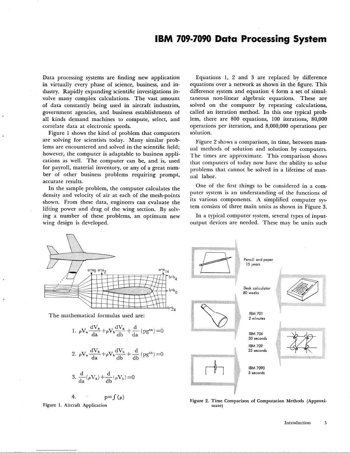
In
the
sample
problem,
the
computer
calculates
the
density
and
velocity
of
air
at
each
of
the
mesh-points
shown.
From
these
data,
engineers
can
evaluate
the
lifting
power
and
drag
of
the
wing
section. By solv-
ing a number
of
these problems,
an
optimum
new
wing design is developed.
The
mathematical
formulas used are:
4.
p=
f (p)
Figure 1. Aircraft
Application
Equations
1, 2 and 3 are
replaced
by difference
equations
over a network
as
shown
in
the
figure.
This
difference system
and
equation 4 form
a set
of
simul-
taneous
non-linear
algebraic equations.
These
are
solved
on
the
computer
by
repeating
calculations,
called
an
iteration
method.
In
this
one
typical prob-
lem,
there
are
800 equations,
100
iterations, 80,000
operations
per
iteration,
and
8,000,000
operations
per
solution.
Figure 2 shows a comparison,
in
time, between
man-
ual
methods
of
solution
and
solution
by computers.
The
times
are
approximate.
This
comparison
shows
that
computers
of
today now have
the
ability
to solve
problems
that
cannot
be solved
in
a lifetime
of
man-
ual
labor.
One
of
the
first things to be considered
in
a com-
puter
system is
an
understanding
of
the
functions
of
its various components. A simplified
computer
sys-
tem consists
of
three
main
units
as
shown
in
Figure
3.
In
a typical
computer
system, several types
of
input-
output
devices
are
needed.
These
may be
units
such
~
r\
\ Pencil and paper
{
15
years
Desk
calculator
80 weeks
IBM
701
2 minutes
IBM
704
30 seconds
IBM
709
25 seconds
IBM
7090
5 seconds
Figure
2.
Time
Comparison
of
Computation
Methods (Approxi-
mate)
Introduction
5
Page 7
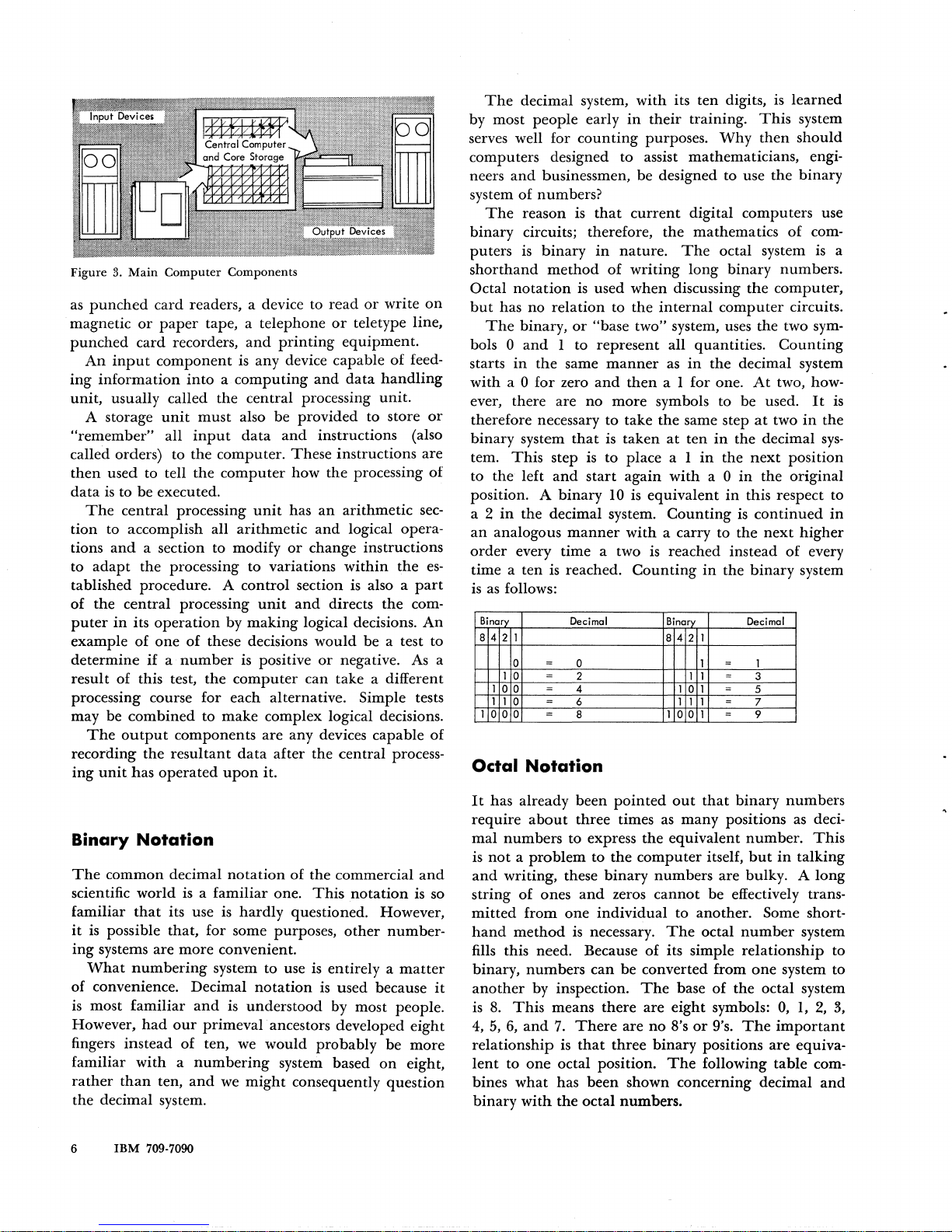
Figure
3.
Main
Computer
as
punched
magnetic
punched
An
ing
information
unit,
A storage
"remember"
card
or
paper
card
recorders,
input
component
usually called
unit
all
called orders) to
then
used
to tell
data
is
to be executed.
The
central
tion
to accomplish all
tions
and
adapt
to
processing
a section to modify
the
processing
tablished procedure. A
of
the
central
puter
in
example
determine
result
of this test,
processing
its
operation
of
one
if a number
Components
readers, a device to
tape, a
telephone
and
is
any
printing
device
into a computing
the
must
input
the
computer.
the
computer
central
also be
data
unit
processing
provided
and
These
how
has
arithmetic
or
to
variations
control
by
making
of
these decisions
section is also a
unit
and
logical decisions.
is positive
the
computer
can
read
or
write
on
or
teletype line,
equipment.
capable
and
data
of
feed-
handling
unit.
to store
or
instructions (also
instructions are
the
processing
an
arithmetic
and
logical opera-
of
sec-
change instructions
within
the
es-
part
directs
the
com-
An
would
be a test to
or
negative. As a
take
a different
processing course for each alternative. Simple tests
may be
The
output
recording
ing
unit
combined
the
has
to
components
resultant
operated
make
data
upon
complex
are
any devices
after
it.
logical decisions.
capable
the
central
process-
of
The
decimal system,
by most
serves well for
people
early
counting
computers designed
neers
and
businessmen, be designed to use
system
binary
puters
shorthand
Octal
but
bols 0
starts
with
ever, there
of
numbers?
The
reason
circuits; therefore,
is
binary
method
notation
has
no
relation
The
binary,
and
1 to
in
the
same
a 0
for
zero
are
is
is used
or
no
therefore necessary to take
binary
tem.
to
position. A
a 2
an
order
time a
is
Octal
the
system
This
left
that
step is to place a I
and
start
binary
in
the
decimal system.
analogous
every
as
follows:
Binar)
8 4 2 1
0
1
0
100
1 1 0
0
1
o 0 - 8 1 0 o 1 - 9
ten
manner
time
is
reached.
Decimal
=
0 1
2 1 1 - 3
-
-
4
- 6
Notation
with
its
in
their
purposes.
to
assist
that
current
the
in
nature.
of
writing
when
to
the
The
discussing
internal
"base two" system, uses
represent
manner
and
more
is
taken
10
all
as
then
a I for one.
symbols to be used.
the
same step
at
again
with
is
equivalent
Counting
with
a carry to
a two is reached
Counting
Binary
84
1 0 1
11
ten
digits, is
training.
Why
This
then
mathematicians,
the
digital
mathematics
computers
of
octal system
long
binary
numbers.
the
computer,
computer
the
two sym-
quantities.
in
the
ten
in
in
the
a 0
in
instead
in
the
2 1
=
-
1
=
Counting
decimal system
At
two, how-
at
two
the
decimal
next
position
in
the
this respect to
is
continued
the
next
of
binary
Decimal
1
5
7
learned
system
should
engi-
binary
use
com-
is
circuits.
It
is
in
the
sys-
original
in
higher
every
system
a
Binary
The
scientific
familiar
it
is possible
ing
What
of convenience. Decimal
is
However,
fingers
familiar
rather
the
6
Notation
common
systems
most
than
decimal system.
IBM
decimal
world
that
its use is
that,
are
numbering
familiar
had
our
instead
with a numbering
ten,
709-7090
is a
for
more
and
primeval
of
ten, we
and
notation
familiar
of
one.
hardly
some purposes,
convenient.
system
to
use
notation
is
understood
ancestors developed
would
system based
we
might
the
This
questioned. However,
is
is
probably
consequently
commercial
notation
other
entirely a
used
and
is so
number-
matter
because
by most people.
eight
be
more
on
eight,
question
It
has
already
require
mal
is
and
string
mitted
hand
about
numbers
not a problem
writing, these
of
ones
from
method
fills this need. Because
it
binary,
another
is
4, 5,
numbers
by inspection.
8.
This
6,
and
means
7.
relationship
lent
to
one
bines
what
binary
with
been
pointed
three
times as
to express
to
the
computer
the
binary
and
zeros
one
individual
is necessary.
of
can
be
converted from
The
there
are
There
is
that
are
three
octal position.
has
been
shown
the
octal
numbers.
out
many
equivalent
numbers
cannot
to
The
its simple
base
eight
no
8's
binary
The
concerning
that
binary
numbers
positions as deci-
number.
itself,
but
in
talking
are bulky. A
be effectively trans-
another.
octal
Some short-
number
system
relationship
one
system
of
the
octal system
symbols:
or
9's.
positions
following
The
0,
1,
important
are
equiva-
table
decimal
This
long
to
to
2,
3,
com-
and
Page 8
BINARY
OCTAL
DECIMAL
0
0 0
1 1 1
10
2
2
11
3
3
100
4 4
101
5 5
110
6 6
III
7 7
At
this
point
a carry to
the
next
higher
position
of
the
number
is necessary, since all
eight
symbols
in
the
octal system have
been
used.
1000
1001
1010
1011
10
II
12
13
8
9
10
11
As
far
as
the
internal
circuitry
of
the
computer
is
con-
cerned,
it
only
understands
binary
ones
and
zeros.
The
octal system
is
used
to
provide a shorthand
method
of
reading
and
writing
binary
numbers
so
that
the
contents
of
a register,
when
shown
on
the
operator's
panel,
may
be
read
directly.
This
is
shown
in
Figure 4,
using
a 36-digit
binary
number.
Reg;
ster contents (b; nary)
Octal
value
Figure
4.
Binary
Representation
of Register
Contents
Magnetic
Cores
The
main
storage
medium
for
many
computers
is
the
magnetic
core.
Each
magnetic core is a
ring
or
doughnut
shaped
piece
of
ferromagnetic
material.
The
cores "remem-
ber"
information
indefinitely,
and
can
recall
it
in
a
few
millionths
of
a second.
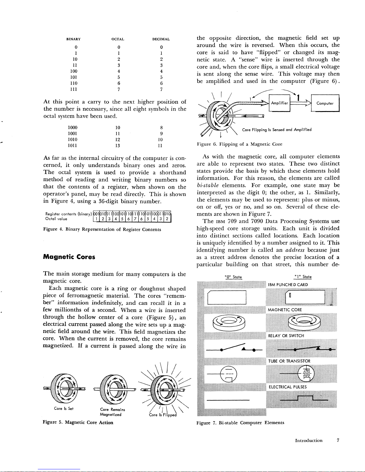
When
a wire
is
inserted
through
the
hollow
center
of
a core (Figure
5),
an
electrical
current
passed
along
the
wire sets
up
a mag-
netic
field
around
the
wire.
This
field magnetizes
the
core.
When
the
current
is removed,
the
core
remains
magnetized.
1£
a
current
is
passed
along
the
wire
in
Core
Is
Set
Figure
5. Magnetic Core Action
the
opposite
direction,
the
magnetic
field set
up
around
the wire is reversed.
When
this occurs,
the
core
is
said to have
"flipped"
or
changed
its mag-
netic state. A
"sense" wire
is
inserted
through
the
core
and,
when
the
core flips, a small electrical voltage
is sent along
the
sense wire.
This
voltage
may
then
be amplified
and
used
in
the
computer
(Figure
6).
Computer
Figure 6.
Flipping
of a Magnetic Core
As
with
the
magnetic core, all
computer
elements
are
able
to
represent
two states.
These
two
distinct
states
provide
the basis by
which
these elements
hold
information.
For
this reason,
the
elements
are
called
bi-stable elements.
For
example,
one
state
may
be
interpreted
as
the
digit
0;
the
other,
as
1.
Similarly,
the
elements may be used to represent:
plus
or
minus,
on
or
off,
yes
or
no,
and
so on. Several of these ele-
ments are shown
in
Figure
7.
The
IBM
709
and
7090
Data
Processing Systems use
high-speed core storage units.
Each
unit
is
divided
into
distinct sections called locations.
Each
location
is
uniquely
identified by a
number
assigned to it.
This
identifying
number
is
called
an
address because
just
as
a street address denotes
the
precise
location
of
a
particular
building
on
that
street, this
number
de-
liD
..
State
Figure
7.
Bi·stable
Computer
Elements
Introduction
7
Page 9
Number 1500
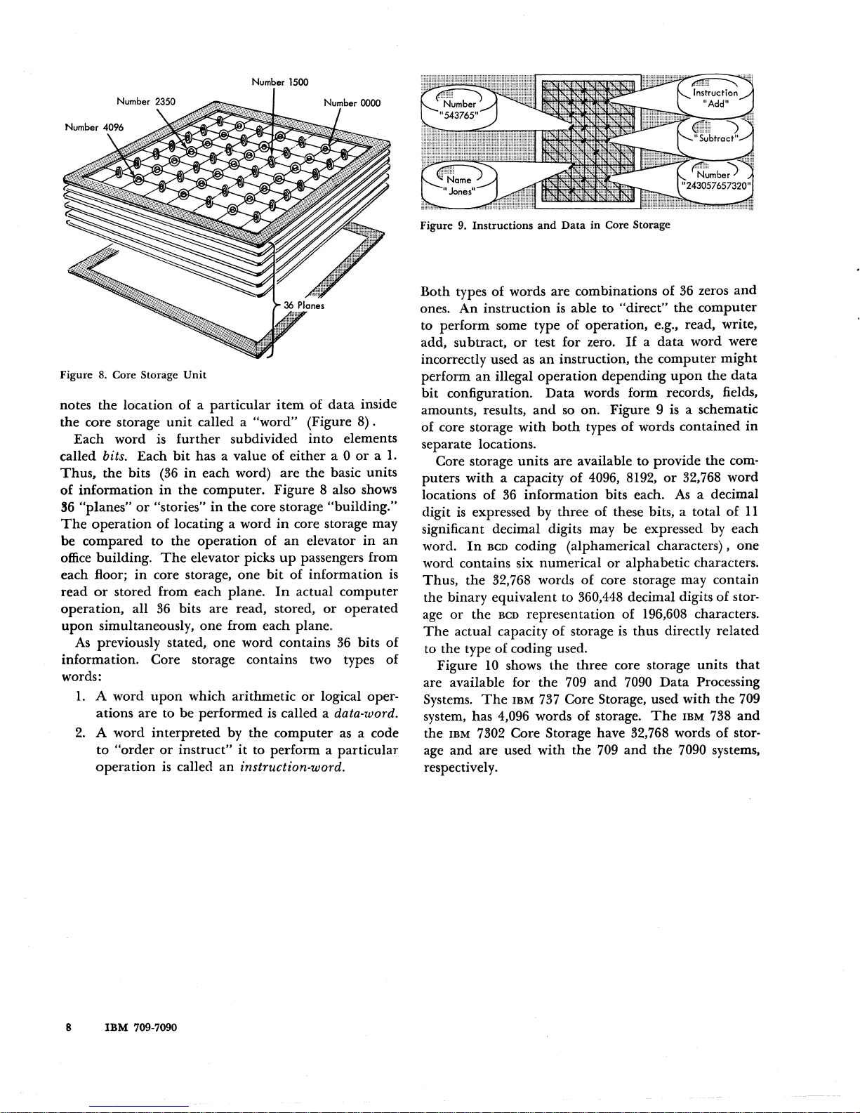
Figure
8.
Core Storage
Unit
notes the location of a
particular
item
of
data
inside
the core storage
unit
called a
"word"
(Figure
8).
Each word is
further
subdivided
into
elements
called
bits. Each
bit
has a value
of
either
a 0
or a 1.
Thus.
the bits
(36
in
each word)
are
the basic units
of
information
in
the computer. Figure 8 also shows
S6
"planes"
or
"stories"
in
the core storage "building."
The
operation
of locating a word
in
core storage may
be compared to the
operation
of
an
elevator
in
an
office
building.
The
elevator picks
up
passengers from
each floor;
in
core storage,
one
bit
of
information is
read
or
stored from each plane.
In
actual computer
operation, all
36
bits are read, stored,
or
operated
upon
simultaneously, one from each plane.
As
previously stated, one word contains
36
bits
of
information. Core storage contains two types of
words:
1.
A word
upon
which arithmetic
or
logical oper-
ations are to be performed
is
called a data-word.
2.
A word
interpreted
by the
computer
as a code
to
"order
or
instruct"
it
to perform a
particular
operation
is
called an instruction-word.
8
IBM
709-7090
Figure 9. Instructions
and
Data
in
Core Storage
Both types of words are combinations of
36
zeros
and
ones.
An
instruction is able to "direct"
the
computer
to perform some type
of
operation, e.g., read. write,
add, subtract,
or
test for zero.
If
a
data
word were
incorrectly used
as
an
instruction, the computer
might
perform
an
illegal
operation
depending
upon
the
data
bit
configuration.
Data
words form records. fields,
amounts, results,
and
so
on. Figure 9 is a schematic
of core storage
with
both
types
of
words contained
in
separate locations.
Core storage
units
are available to provide the com-
puters
with
a capacity
of
4096, 8192,
or
32,768 word
locations of
36
information
bits each. As a decimal
digit is expressed by three
of
these bits, a total of
II
significant decimal digits may be expressed by each
word.
In
BCD coding (alphamerical characters),
one
word contains six numerical
or
alphabetic characters.
Thus,
the 32,768 words of core storage may contain
the binary equivalent to
360,448 decimal digits of stor-
age
or
the BCD representation of 196,608 characters.
The
actual capacity of storage is thus directly related
to the type of coding used.
Figure
10
shows the three core storage units
that
are available for the 709
and
7090
Data
Processing
Systems.
The
IBM
737
Core Storage, used
with
the 709
system, has 4,096 words
of
storage.
The
IBM
738
and
the
IBM
7302 Core Storage have 32,768 words
of
stor-
age
and
are used
with
the
709
and
the 7090 systems,
respectively.
Page 10
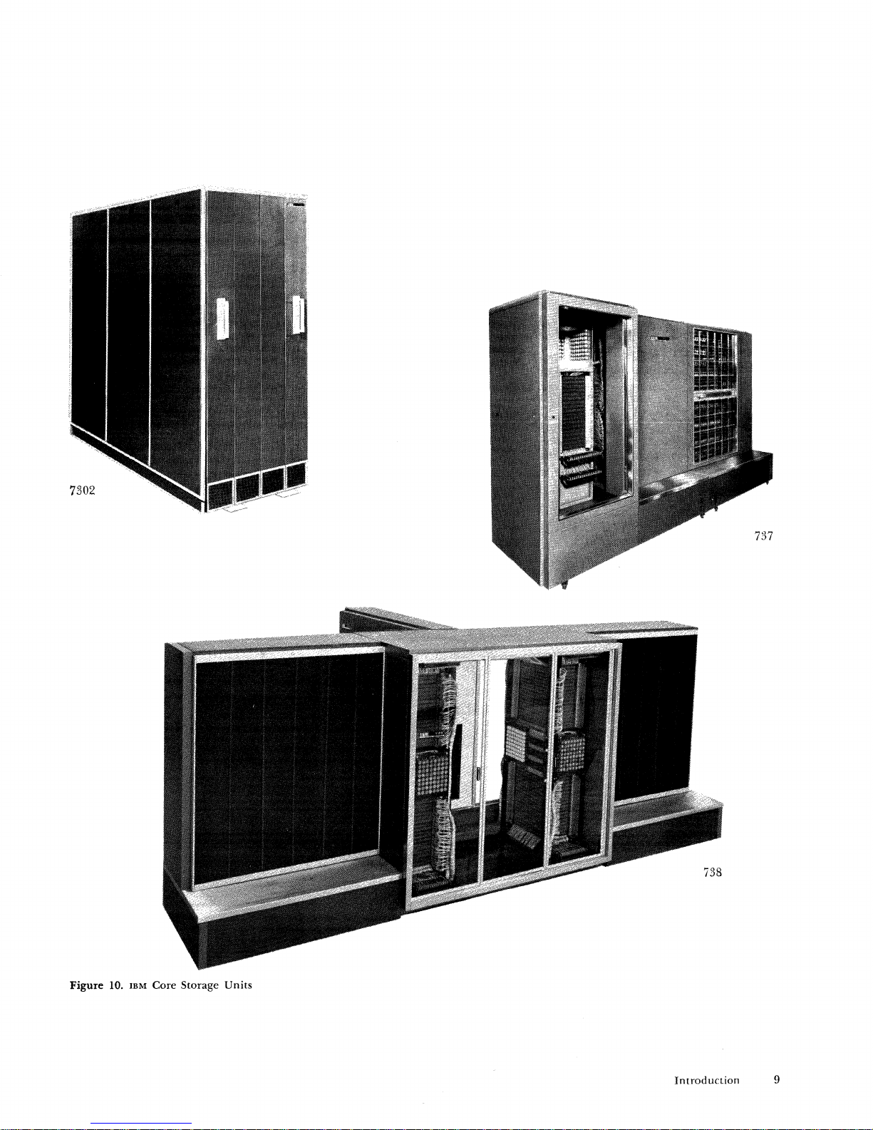
Figure
10.
IBM Core Storage
Units
Introduction
9
Page 11
Central Processing
Unit
The
central processing
unit
can
be divided
into
two
basic parts,
information
processing elements
and
exe-
cution
controls.
The
information
processing elements
are normally referred to
as
the
arithmetic
section.
The
execution controls are called simply
the
control
section.
The
arithmetic
section
is
the
computer's problem-
solving
unit.
The
operations
of
addition, subtraction,
multiplication,
and
division, as well as shifting, trans-
ferring,
and
storing
of
results are executed
in
this
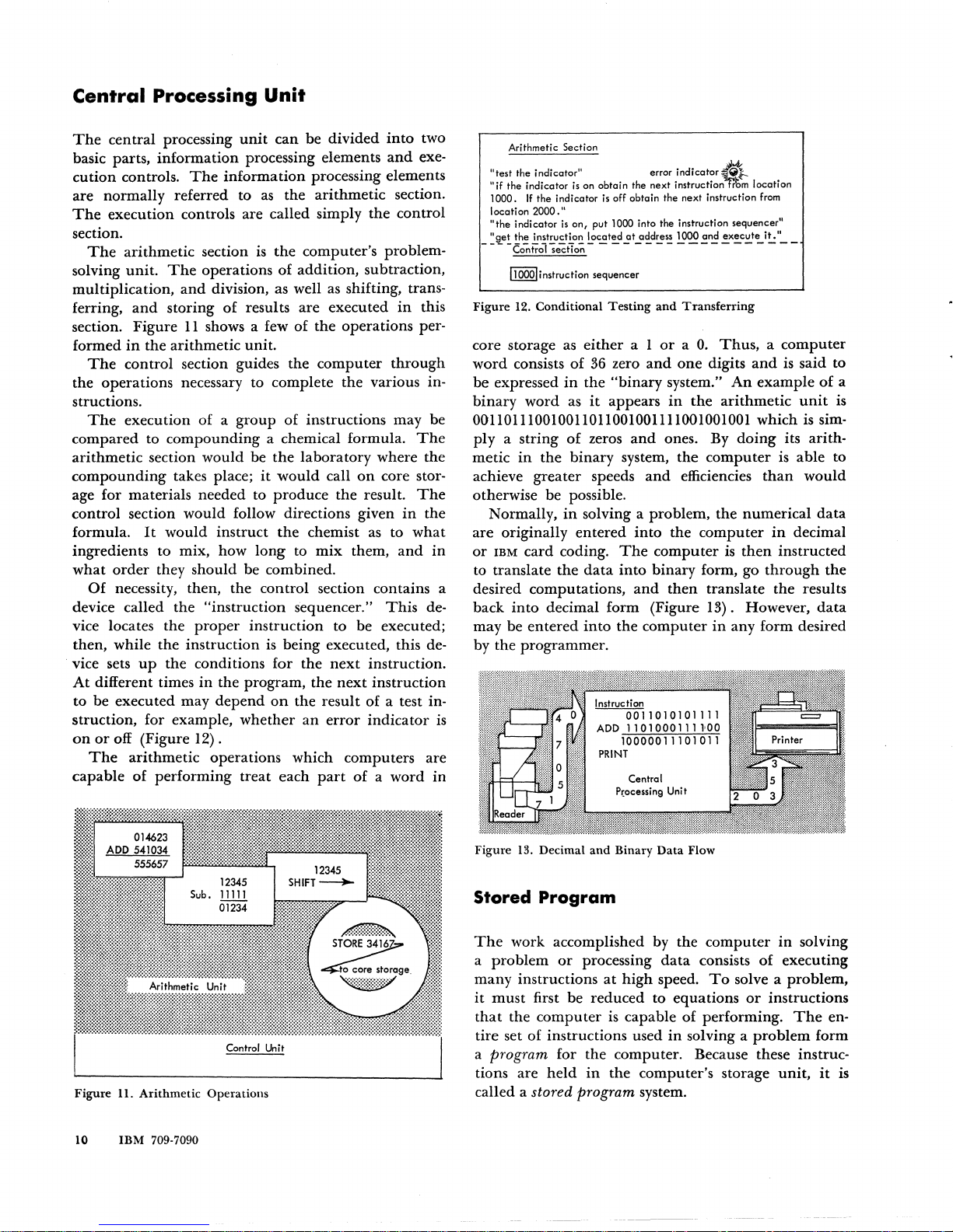
section. Figure
11
shows a few of
the
operations per-
formed
in
the
arithmetic
unit.
The
control section guides the
computer
through
the
operations necessary to complete
the
various in-
structions.
The
execution
of a group
of
instructions may be
compared to
compounding
a chemical formula.
The
arithmetic
section would be
the
laboratory where the
compounding
takes place;
it
would
call
on
core stor-
age for materials needed to
produce
the
result.
The
control section would follow directions given
in
the
formula.
It
would instruct
the
chemist as to
what
ingredients to mix, how
long
to
mix
them,
and
in
what
order
they should be combined.
Of
necessity, then, the control section contains a
device called
the
"instruction
sequencer."
This
de-
vice locates
the
proper
instruction to be executed;
then, while
the
instruction
is
being executed, this de-
vice sets
up
the
conditions for
the
next
instruction.
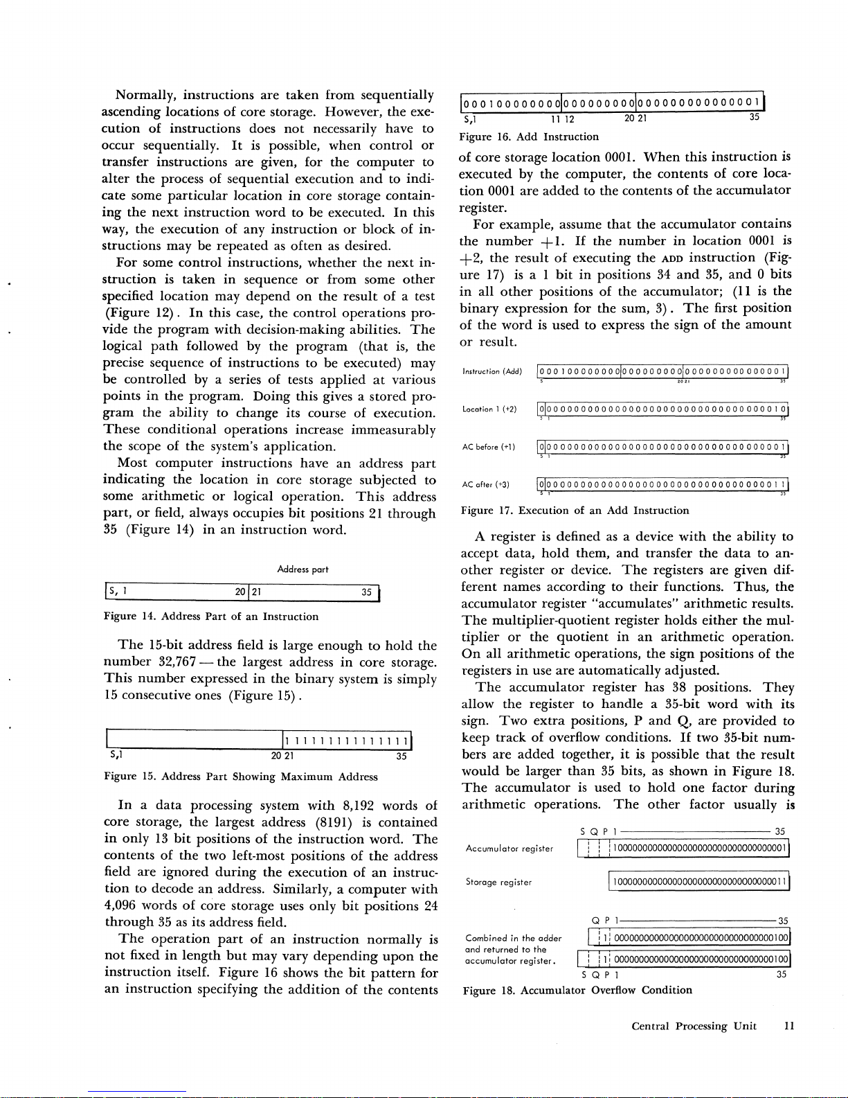
At
different times
in
the program,
the
next
instruction
to
be
executed may
depend
on
the result of a test in-
struction, for example,
whether
an
error
indicator
is
on
or
off (Figure
12)
.
The
arithmetic
operations which computers are
capable
of
performing
treat
each
part
of
a word
in
014623
ADD
541034
555657
12345
Sub.
11111
01234
':"_
,,'_"'~"~
Unit
Control
Un
i t
Figure
II.
Arithmetic
Operations
10
IBM
709·7090
12345
SHIFT~
~
~
STORE
3416
Arithmetic Section
"test the indicator!!
error
indicator«.t-.
"if
the indicator
is
on obtain the next instruction-from location
1000.
If
the indicator
is
off obtain the next instruction
from
location
2000."
"the
indicator
is
on,
put 1000 into the instruction sequencer"
"get
the instruction located
at
address 1000 and
execute
it."
- - - -
COntral
se~iia;;
- - - - - - - - - - - - - - - - -
--
11000!;nstructian sequencer
Figure
12.
Conditional
Testing
and
Transferring
core storage as
either
a 1
or
a
O.
Thus, a computer
word
consists
of
36 zero
and
one
digits
and
is said to
be
expressed
in
the
"binary
system."
An
example
of
a
binary
word
as
it
appears
in
the
arithmetic
unit
is
001101110010011011001001111001001001 which is sim-
ply
a string
of
zeros
and
ones. By
doing
its arith-
metic
in
the
binary system,
the
computer
is able to
achieve
greater
speeds
and
efficiencies
than
would
otherwise be possible.
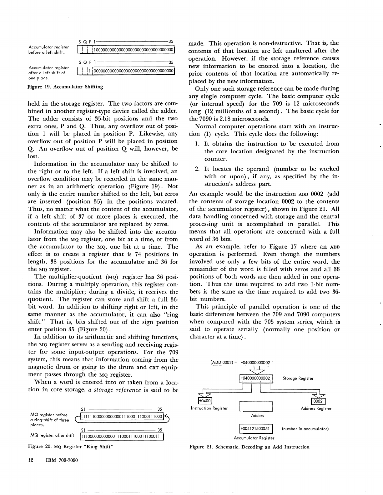
Normally,
in
solving a problem,
the
numerical
data
are
originally
entered
into
the
computer
in
decimal
or
IBM
card
coding.
The
computer
is
then
instructed
to translate
the
data
into
binary form, go
through
the
desired computations,
and
then
translate
the
results
back
into
decimal form (Figure 13). However,
data
may be
entered
into
the
computer
in
any form desired
by the programmer.
Instruction
0011010101111
ADD
11010001111,00
10000011101011
PRINT
Central
P(ocessing
Unit
Figure
13. Decimal
and
Binary
Data
Flow
Stored
Program
The
work accomplished by the
computer
in
solving
a
problem
or
processing
data
consists
of
executing
many
instructions
at
high
speed.
To
solve a problem,
it
must
first
be
reduced to equations
or
instructions
that
the
computer
is capable
of
performing.
The
en-
tire set
of
instructions used
in
solving a
problem
form
a program for
the
computer. Because these instruc-
tions are
held
in
the computer's storage
unit,
it
is
called a stored program system.
Page 12
Normally, instructions
are
taken
from
sequentially
ascending locations
of
core storage. However,
the
exe-
cution
of
instructions does
not
necessarily have
to
occur
sequentially.
It
is possible,
when
control
or
transfer
instructions
are
given, for
the
computer
to
alter
the
process
of
sequential
execution
and
to
indi-
cate
some
particular
location
in
core storage contain-
ing
the
next
instruction
word
to
be
executed.
In
this
way,
the
execution
of
any
instruction
or
block
of
in-
structions
may
be
repeated
as
often
as desired.
For
some
control
instructions,
whether
the
next
in-
struction
is
taken
in
sequence
or
from
some
other
specified location
may
depend
on
the
result
of
a test
(Figure
12).
In
this case,
the
control
operations
pro-
vide
the
program
with
decision-making abilities.
The
logical
path
followed by
the
program
(that
is,
the
precise sequence
of
instructions to
be
executed) may
be
controlled
by a series
of
tests
applied
at
various
points
in
the
program.
Doing
this gives a
stored
pro-
gram
the
ability
to
change
its course of execution.
These
conditional
operations
increase
immeasurably
the
scope
of
the
system's
application.
Most
computer
instructions
have
an
address
part
indicating
the
location
in
core storage
subjected
to
some
arithmetic
or
logical
operation.
This
address
part,
or
field, always occupies
bit
positions
21
through
35 (Figure 14)
in
an
instruction
word.
Address
part
I
s,
I
Figure
14. Address
Part
of
an
Instruction
The
15-bit address field is large
enough
to
hold
the
number
32,767 -
the
largest address
in
core storage.
This
number
expressed
in
the
binary
system is simply
15
consecutive ones (Figure 15) .
II
III
I I
11111
11111
S,1
2021
35
Figure
15. Address
Part
Showing
Maximum
Address
In a data
processing system
with
8,192 words of
core storage,
the
largest address (8191)
is
contained
in
only
13
bit
positions
of
the
instruction
word.
The
contents
of
the
two left-most positions
of
the
address
field
are
ignored
during
the
execution
of
an
instruc-
tion
to
decode
an
address. Similarly, a
computer
with
4,096 words
of
core storage uses
only
bit
positions 24
through
35
as
its address field.
The
operation
part
of
an
instruction
normally
is
not
fixed
in
length
but
may
vary
depending
upon
the
instruction
itself.
Figure
16
shows
the
bit
pattern
for
an
instruction
specifying
the
addition
of
the
contents
S,1
35
Figure
16.
Add
Instruction
of
core storage
location
0001.
When
this
instruction
is
executed
by
the
computer,
the
contents
of
core loca-
tion
0001
are
added
to
the
contents
of
the
accumulator
register.
For
example, assume
that
the
accumulator
contains
the
number
+1.
If
the
number
in
location
0001
is
+2,
the
result
of
executing
the
ADD
instruction
(Fig-
ure
17) is a 1
bit
in
positions 34
and
35,
and
0 bits
in
all
other
positions
of
the
accumulator;
(II
is
the
binary
expression for
the
sum,
3).
The
first
position
of
the
word
is
used
to express
the
sign
of
the
amount
or
result.
Instruction
(Add)
location 1
(+2)
000000000000000000000000000000000010
, ,
AC
before
(+1)
a a a
000
a a a a 0 a
000
a a 0 a 0 0 a 0 0 0 a 0 0 a
00
a 0 a
01
,
AC
after
(+3)
1010000
a 0 0 0 0 0 a a 0 0 0 a a 0 a a a 0 a 0 0 a
00000
a a 1
Ii
s 1
J5
Figure
17.
Execution
of
an
Add
Instruction
A register is defined
as
a device
with
the
ability
to
accept
data,
hold
them,
and
transfer
the
data
to
an-
other
register
or
device.
The
registers
are
given dif-
ferent
names according to
their
functions.
Thus,
the
accumulator
register
"accumulates"
arithmetic
results.
The
multiplier-quotient
register
holds
either
the
mul-
tiplier
or
the
quotient
in
an
arithmetic
operation.
On
all
arithmetic
operations,
the
sign positions
of
the
registers
in
use
are
automatically
adjusted.
The
accumulator
register has 38 positions.
They
allow
the
register to
handle
a 35-bit
word
with
its
sign.
Two
extra
positions, P
and
Q,
are
provided
to
keep
track
of
overflow conditions.
If
two 35-bit
num-
bers
are
added
together,
it
is possible
that
the
result
would
be
larger
than
35 bits, as
shown
in
Figure
18.
The
accumulator
is
used to
hold
one
factor
during
arithmetic
operations.
The
other
factor usually is
Accumulator
register
Storage register
Combined in
the
adder
and
returned
to
the
accumulator
register.
S Q P I
35
! ! ! 1 000000000000000000000000000000000 1
1100000000000000000000000000000000111
Q P 1
35
I !
Ii
000000000000000000000000000000001001
!
iIi
000000000000000000000000000000001001
S Q P 1
35
}1igure 18.
Accumulator
Overflow
Condition
Central
Processing
Unit
11
Page 13
Accumulator register
before a
left
shift.
5 Q P 1 35
I ! ! :100000000000000000000000000000000001
5 Q P
1-----------35
Accumulator register I I I i I
after
a left shift
of
I
11
100000000000000000000000000000000000
one
place.
Figure
19.
Accumulator
Shifting
held
in
the
storage register.
The
two factors
are
com-
bined
in
another
register-type device called
the
adder.
The
adder
consists
of
35-bit positions
and
the
two
extra
ones, P
and
Q.
Thus,
any overflow
out
of
posi-
tion
1 will
be
placed
in
position
P. Likewise, any
overflow
out
of
position P will
be
placed
in
position
Q.
An
overflow
out
of
position Q will, however, be
lost.
Information
in
the
accumulator
may be shifted to
the
right
or
to the left.
1£
a left shift is involved,
an
overflow
condition
may
be
recorded
in
the
same man-
ner
as
in
an
arithmetic
operation
(Figure
19).
Not
only
is
the
entire
number
shifted
to
the
left,
but
zeros
are
inserted (position 35)
in
the
positions vacated.
Thus,
no
matter
what
the
content
of
the
accumulator,
if a left
shift
of
37
or
more
places is executed,
the
contents
of
the
accumulator
are
replaced by zeros.
Information
may also
be
shifted
into
the
accumu-
lator
from
the
MQ
register,
one
bit
at
a time,
or
from
the
accumulator
to the
MQ,
one
bit
at
a time.
The
effect is to create a register
that
is
74 positions
in
length,
38
positions for the
accumulator
and
36 for
the
MQ
register.
The
multiplier-quotient
(MQ)
register has
36
posi-
tions.
During a multiply
operation,
this register con-
tains
the
multiplier;
during
a divide,
it
receives
the
quotient.
The
register
can
store
and
shift a full
36-
bit
word.
In
addition
to shifting
right
or
left,
in
the
same
manner
as
the
accumulator,
it
can
also
"ring
shift."
That
is, bits shifted
out
of
the
sign position
enter
position
35
(Figure
20)
.
In
addition
to its
arithmetic
and
shifting functions,
the
MQ
register serves
as
a sending
and
receiving regis-
ter
for some
input-output
operations.
For
the
709
system, this means
that
information
coming from
the
magnetic
drum
or
going to
the
drum
and
CRT
equip-
ment
passes
through
the
MQ
register.
When a word
is
entered
into
or
taken
from a loca-
tion
in
core storage, a storage reference is said to
be
51
35
MQ
register before 111111000000000000111000111000111
000
a
ring-shift
of
three
places.
51
35
MQ
register
after
shift 11110000000000001110001110001110001111
Figure
20.
MQ
Register
"Ring
Shift"
12
IBM
709-7090
made.
This
operation
is non-destructive.
That
is,
the
contents
of
that
location
are
left
unaltered
after
the
operation.
However,
if
the
storage reference causes
new
information
to
be
entered
into
a location,
the
prior
contents
of
that
location
are
automatically re-
placed
by
the
new
information.
Only
one
such storage reference
can
be
made
during
any single
computer
cycle.
The
basic
computer
cycle
(or
internal
speed) for
the
709 is 12 microseconds
long
(12
millionths
of a second).
The
basic cycle for
the
7090 is 2.18 microseconds.
Normal
computer
operations
start
with
an
instruc-
tion
(I) cycle.
This
cycle does
the
following:
1.
It
obtains
the
instruction
to
be
executed from
the
core location designated
by
the
instruction
counter.
2.
It
locates
the
operand
(number
to
be
worked
with
or
upon),
if
any, as specified
by
the in-
struction's address
part.
An
example
would
be
the
instruction
ADD 0002 (add
the
contents
of
storage location 0002 to
the
contents
of
the
accumulator
register), shown
in
Figure
21. All
data
handling
concerned
with
storage
and
the
central
processing
unit
is accomplished
in
parallel.
This
means
that
all operations
are
concerned
with
a full
word
of
36 bits.
As
an
example, refer to Figure
17
where
an
ADD
operation
is performed.
Even
though
the
numbers
involved use
only
a few bits
of
the
entire
word,
the
remainder
of
the
word
is filled
with
zeros
and
all 36
positions
of
both
words
are
then
added
in
one
opera-
tion.
Thus
the
time
required
to
add
two
I-bit
num-
bers is
the
same
as
the
time
required
to
add
two
36-
bit
numbers.
This
principle
of
parallel
operation
is
one
of
the
basic differences between
the
709
and
7090 computers
when
compared
with
the
705 system series, which is
said
to
operate
serially (normally om;
position
or
character
at
a time) .
(ADD 0002) =
~
Instruction Register
5torage Register
~
Address Register
Adders
1-+004121503051
I (number in accumulator)
Accumulator
Register
Figure
21. Schematic, Decoding
an
Add
Instruction
Page 14
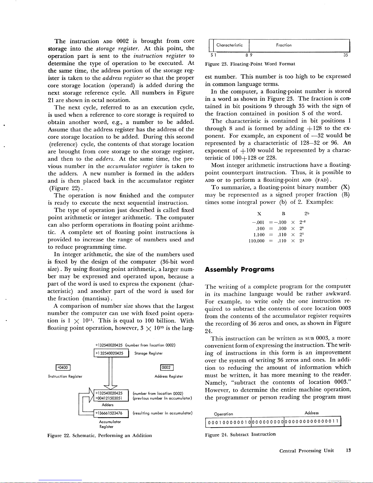
The
instruction
ADD 0002
is
brought
from
core
storage
into
the
storage register.
At
this
point,
the
operation
part
is sent to
the
instruction register
to
determine
the
type
of
operation
to be executed.
At
the
same time,
the
address
portion
of
the
storage reg-
ister is
taken
to
the
address register so
that
the
proper
core storage
location
(operand) is
added
during
the
next
storage reference cycle.
All
numbers
in
Figure
21
are
shown
in
octal
notation.
The
next
cycle,
referred
to as
an
execution
cycle,
is used
when
a reference to core storage is
required
to
obtain
another
word, e.g., a
number
to be added.
Assume
that
the
address register has
the
address
of
the
core storage location to be added.
During
this second
(reference) cycle, the contents
of
that
storage location
are
brought
from core storage to
the
storage register,
and
then
to
the
adders.
At
the
same time,
the
pre-
vious
number
in
the
accumulator register
is
taken
to
the
adders. A
new
number
is
formed
in
the
adders
and
is
then
placed
back
in
the
accumulator
register
(Figure
22).
The
operation
is
now
finished
and
the
computer
is
ready
to execute
the
next
sequential
instruction.
The
type
of
operation
just
described is
called
fixed
point
arithmetic
or
integer
arithmetic.
The
computer
can
also
perform
operations
in
floating
point
arithme-
tic. A
complete
set
of
floating
point
instructions
is
provided
to
increase
the
range
of
numbers
used
and
to
reduce
programming
time.
In
integer
arithmetic,
the
size
of
the
numbers
used
is fixed by
the
design
of
the
computer
(36-bit
word
size) . By
using
floating
point
arithmetic, a larger
num-
ber
may
be
expressed
and
operated
upon,
because a
part
of
the
word
is used to express
the
exponent
(char-
acteristic)
and
another
part
of
the
word
is
used
for
the
fraction
(mantissa).
A
comparison
of
number
size shows
that
the
largest
number
the
computer
can
use
with
fixed
point
opera-
tion
is
I X
1011.
This
is
equal
to 100 billion.
With
floating
point
operation,
however, 3 X
10
35
is
the
larg-
Instruction Register
+132540020425 (number
from
location 0002)
+1
32540020425
Accumulator
Register
Storage Register
Address
Reg
i ster
(number
from
location 0002)
(previous
number
in accumulator)
(resulting number
in
accumulator)
Figure
22. Schematic,
Performing
an
Addition
I
Characteristic
Fraction
51
8 9
35
Figure
23.
Floating-Point
Word
Format
est
number.
This
number
is too
high
to be expressed
in
common
language
terms.
In
the
computer,
a floating-point
number
is stored
in a word
as shown
in
Figure 23.
The
fraction
is
con-
tained
in
bit
positions 9
through
35
with
the
sign of
the
fraction
contained
in
position S of
the
word.
The
characteristic
is
contained
in
bit
positions 1
through 8 and
is
formed
by
adding
+128
to
the
ex-
ponent.
For
example,
an
exponent
of
-32
would
be
represented
by a characteristic
of
128-32
or
96.
An
exponent
of
+ 1
00
would
be
represented
by a charac-
teristic
of
100+128
or
228.
Most
integer
arithmetic
instructions
have
a floating-
point
counterpart
instruction.
Thus,
it
is
possible to
ADD
or
to
perform
a floating-point ADD
(FAD).
To
summarize, a floating-point
binary
number
(X)
may be
represented
as
a signed
proper
fraction (B)
times some integral power (b) of
2.
Examples:
X
B
2
b
-.001
=-.100
X
2-"
.100
.100
x
2"
l.l00
.110
X
2'
110.000
.110
X
2
3
Assembly
Programs
The
writing
of a complete
program
for
the
computer
in
its
machine
language
would
be
rather
awkward.
For
example, to
write
only
the
one
instruction
re-
quired
to
subtract
the
contents
of
core
location
0003
from
the
contents
of
the
accumulator
register
requires
the
recording
of
36 zeros
and
ones,
as
shown
in
Figure
24.
This
instruction
can
be
written
as
SUB
0003, a
more
convenient
form
of
expressing
the
instruction.
The
writ-
ing
of
instructions
in
this form is
an
improvement
over
the
system
of
writing
36
zeros
and
ones.
In
addi-
tion
to
reducing
the
amount
of
information
which
must
be
written,
it
has.
more
meaning
to
the
reader.
Namely,
"subtract
the
contents
of
location
0003."
However, to
determine
the
entire
machine
operation,
the
programmer
or
person
reading
the
program
must
Operation
Address
Figure
24.
Subtract
Instruction
Central
Processing
Unit
13
Page 15
know
what
is stored
in
location 0003.
To
assist
the
programmer,
the
use
of
symbols
can
be
extended
to
in-
clude addresses as well as
the
operation
part
of
an
in-
struction.
Assuming
that
the
net
pay
for a payroll calculation
is
stored
in
location 0003,
the
instruction
might
now
be
written
as
"subtract
net."
This
clarifies to the pro-
grammer
the
operation
to be performed,
and
also
what
quantity
is involved.
Thus,
symbolic
programming
employs instruction-by-instruction coding
in
a lan-
guage
that
is a representation
of
the
basic language
of
the
computer
itself.
The
computer
can
execute instructions only
if
,they
are stored
in
machine language.
Thus,
the
instruction
"subtract
net"
must be converted to
the
basic
machine
language before its execution.
One
way
of
doing this
would be to
manually
convert all symbolic instruc-
tions to machine language before
entering
them
into
the
computer.
This
obviously would be a laborious
task. A more practical solution
is
to have
the
com-
puter
perform
the
conversion.
This
is accomplished
through
use
of
a symbolic assembly program.
An
assembly
program
performs
the
necessary trans-
lation
or
conversion from
the
symbolic language to
the machine language.
At
the
same time,
the
program
assigns absolute core storage locations to
the
imtruc-
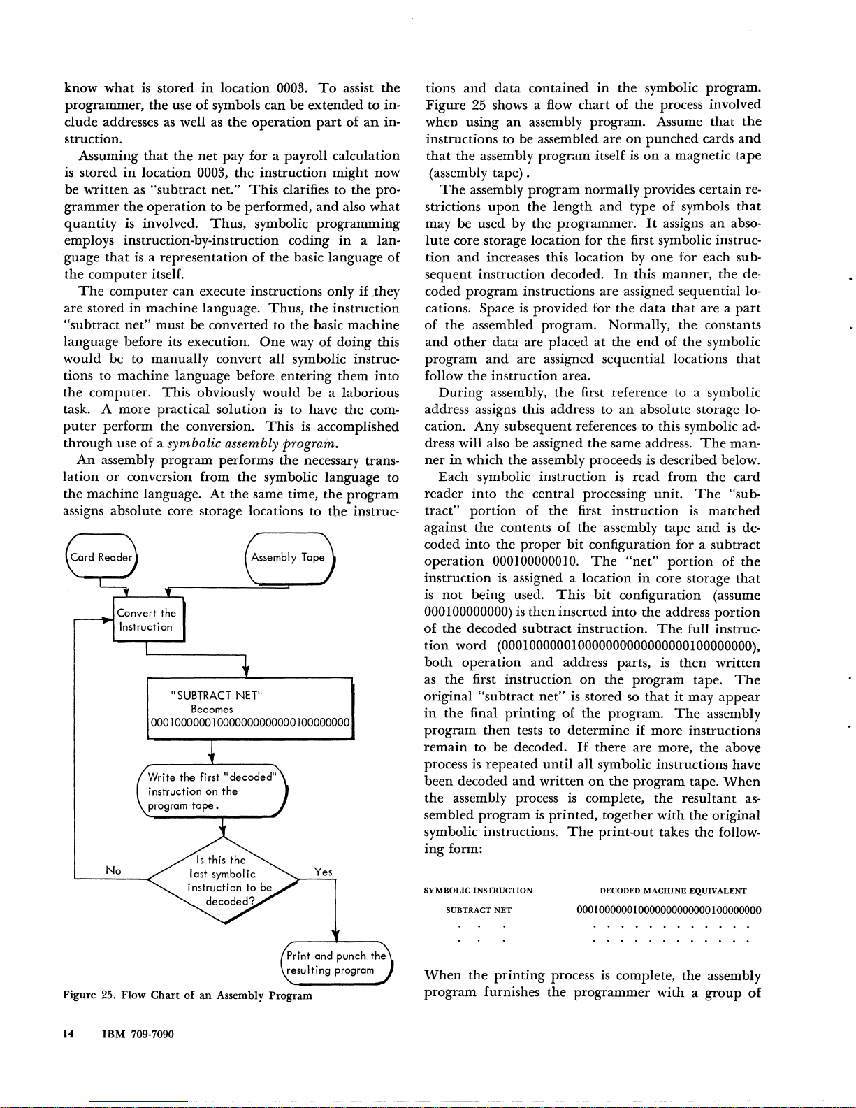
Convert
the
Instructi on
"SUBTRACT NET"
Becomes
000100000010000000000000100000000
No
Yes
Print
and
punch
the
resulting
program
Figure 25. Flow
Chart
of
an
Assembly
Program
14
IBM
709-7090
tions
and
data
contained
in
the
symbolic program.
Figure
25
shows a flow
chart
of
the
process involved
when using
an
assembly program. Assume
that
the
instructions to
be
assembled are
on
punched
cards
and
that
the
assembly
program
itself is
on
a magnetic tape
(assembly tape) .
The
assembly
program
normally provides certain re-
strictions
upon
the
length
and
type
of
symbols
that
may
be used by
the
programmer.
It
assigns
an
abso-
lute
core storage location for
the
first symbolic instruc-
tion
and
increases this location by
one
for each sub-
sequent
instruction decoded.
In
this manner, the de-
coded
program
instructions are assigned sequential lo-
cations. Space
is
provided for
the
data
that
are a part
of
the
assembled program. Normally,
the
constants
and
other
data
are placed
at
the
end
of
the
symbolic
program
and
are assigned sequential locations
that
follow
the
instruction area.
During
assembly,
the
first reference to a symbolic
address assigns this address to
an
absolute storage lo-
cation. Any subsequent references to this symbolic address will also be assigned
the
same address.
The
man-
ner
in
which
the
assembly proceeds is described below.
Each
symbolic
instruction
is
read
from
the
card
reader
into
the central processing
unit.
The
"sub-
tract"
portion
of
the
first instruction is
matched
against
the
contents
of
the
assembly tape
and
is de-
coded
into
the
proper
bit
configuration for a
subtract
operation
000100000010.
The
"net"
portion
of
the
instruction
is assigned a location
in
core storage
that
is
not
being
used.
This
bit
configuration (assume
000 100000000)
is
then
inserted
into
the
address
portion
of
the
decoded
subtract
instruction.
The
full instruc-
tion
word
(000100000010000000000000000 I 00000000),
both
operation
and
address parts,
is
then
written
as
the
first instruction
on
the
program
tape.
The
original
"subtract
net"
is stored
so
that
it
may
appear
in
the
final
printing
of
the
program.
The
assembly
program
then
tests to
determine
if
more instructions
remain
to
be
decoded.
If
there
are more,
the
above
process
is
repeated
until
all symbolic instructions have
been
decoded
and
written
on
the
program
tape.
When
the
assembly process is complete,
the
resultant
as-
sembled
program
is
printed,
together
with
the
original
symbolic instructions.
The
print-out
takes
the
follow-
ing
form:
SYMBOLIC
INSTRUCTION
DECODED
MACHINE
EQUIVALENT
SUBTRACT
NET
000100000010000000000000100000000
When
the
printing
process is complete,
the
assembly
program
furnishes the
programmer
with a group
of
Page 16

punched
cards
containing
the
machine
language
trans-
lation
so
that
if
the
program
is used again,
the
as-
sembly process
need
not
be
repeated.
Computer
Operations
The
format
of
the
instruction
word
is, for
the
most
part,
a precise one.
Although
slight
variations
exist,
in
general
the
format
is
as
shown
in
Figure
26.
Operation
part
Flag
Tag
Address part
I I I I
5,
1
11
12-13 18-20
21
35
Figure 26.
Instruction
I'onnat
The
operation
part
usually
is
contained
in
positions
S,
1-11
of
the
instruction
word.
In
the
following text
and
in
program
writing,
an
alphabetic
code
is
used
to
identify
the
instruction
operation
rather
than
the
full
name
of
the
instruction.
Thus,
the
code
CLA
signifies
CLear
and
Add,
or
SUB
means SUBtract.
If
the
numeri-
cal
machine
language
code is to be used,
it
is given
in
the
octal system.
For
example,
+0500
is
the
code
for
the
clear
and add
operation;
+0402
denotes subtrac-
tion.
All
abbreviations are simply
shorthand
methods
used to
reduce
the
manual
task
of
writing a program.
The
flag
part,
or
flag bits, is
contained
in
positions
12
and
13
of
the
word.
It
specifies
that
indirect
ad-
dressing is
to
take place.
This
operation
may
be
per-
formed
only
on
instructions
that
use
index
registers.
Both
indirect
addressing
and
the
use
of
index
registers
are
explained
later
in
the
text.
The
tag
bits
are
contained
in
positions 18, 19,
and
20.
They
specify
which
index
registers
are
to
be used.
Only
a few
instructions
may
not
use
indexing.
The
address
part
of
the
instruction
is
contained
in
positions
21
through
35
of
the
word.
It
tells
the
com-
puter
the
location
or
"operand"
that
is to be
used
with
the
instruction.
In
the
case
of
shifting
operations,
the
address
part
contains
the
number
of
places to
be
shifted.
For
other
instructions,
the
address
part
may
be a
part
of
the
operation
itself. Such a case
would
have
the
address
part
expressed as a four-digit num-
ber; read-1200 means
the
reading
operation
will
take
place
and
the
1200 will tell
which
input-output
unit
is
being
used.
In
this case,
the
tape
unit
numbered
0
on
data
channel A would
be used.
In
executing
the
instruction
ADD
1000,
the
computer
assumes
that
the
augend
is
in
the
accumulator
and
the
addend
(the
number
being
added) is specified
by
the
address
part
of
the
ADD
instruction.
The
sign
of
the
numbers
(S
position) is,
of
course, considered
dur-
ing
an
add
operation.
When
two
numbers
of
the
same
magnitude
are
being
added,
the
sign
of
the
result
is
taken
from
the
number
in
the
accumulator.
ACCUMULATOR
+6
-6
+
+
STORAGE
-6
+6
=
=
RESULT
IN
ACCUMULATOR
+0
-0
The
clear-and-add
(CLA)
instruction
is
similar
to
the
add
instruction
except
that
the
accumulator
is
cleared to zeros
and
the
contents
of
the
location
speci-
fied by
the
address
part
of
the
CLA
instruction
are
placed
in
the
accumulator.
Add
magnitude
(ADM)
is
another
similar
instruc-
tion.
Its
operation
is
the
same
as
ADD
except
that
the
sign
of
the
number
is
ignored
and
the
number
is
treated
as positive.
Other
arithmetic
instructions are
treated
in
a like
manner
since all
arithmetic
processes
are
accomplished
by
addition,
and
complementing a result
where
neces-
sary.
Subtraction
occurs
in
the
following
manner:
7 = 000111
Number
in
Accumulator
5 = 000101
Number
to
be
Subtracted
(Operand)
111000
Complement
of
Number
in
Accumulator
+ 000101
111101
Recomplement
the
Result
(No
High-Order
Carry)
000010
This
is
the
answer, 5
subtracted
from 7 = 2.
Multiplication
is accomplished by testing
the
low-
order
position
of
the
multiplier
and
adding
the
multi-
plicand
if this low-order position is a
1.
After
each
test,
the
answer is shifted
one
place
to
the
left.
This
is
repeated
until
there
are
no
more
numbers
in
the
mul-
tiplier.
5 = 000101
Multiplicand
X3=
000011
Multiplier
000101
000101
000000
15
= 00001111
Product
Division is accomplished
in
a like
manner
but
shift-
ing
occurs
in
the
opposite
direction. By
shifting
a
binary
number
one
place
to
the
left,
the
result
is
the
same as
multiplying
by 2. A
number
shifted
one
place
to
the
right
has
been
divided
by
2.
A
group
of
word
transmission
instructions
is also
provided.
These
instructions
are
concerned
with
the
movement,
at
high
speed,
of
words
or
parts
of
words
from
one
location
or
register
to
another.
In
particu-
lar,
information
may
be
either
stored
or
taken
from
locations
in
core storage
and
various registers
in
the
central
processing
unit.
Since
the
word
transmission
instructions
are
concerned
with
the
movement
of
data,
they
are
used
frequently.
The
store
(STO)
instruction
stores
the
contents
of
the
accumulator
in
the
location specified by
the
ad-
Central
Processing
Unit
15
Page 17

dress
part
of
the
store instruction.
Other
store instruc-
tions accomplish
the
storing
of
the address portion,
tag,
and
other
portions
of
both
the
accumulator
and
the
multiplier-quotient registers.
The
computer
also has certain load instructions
to
accomplish the same
end
as
the
store instructions, ex-
cept
in
reverse. A store instruction places the contents
of
a register
in
storage. Conversely a
load
instruction
takes the contents
of
a storage location
and
places
it
in
a register.
There
are also
load
instructions for
the
index
registers.
With
transmit, store,
or
load
type instructions,
the
contents
of
the storage location
or
register from which
the
data
are being moved
remain
unchanged.
Shift instructions are used to move the contents
of
the accumulator
and/or
the
multiplier-quotient regis-
ters
either
to the
right
or
the left
of
their original posi-
tions.
With
the exception
of
the
rotate-MQ-Ieft instruc-
tion, zeros are automatically inserted
in
the vacated
positions of the register.
Thus,
a shift larger
than
the
bit
capacity
of
the register causes the contents
of
the
register to be lost
and
replaced by zeros.
When
a shift
instruction is interpreted, the
amount
of
the shift is
determined by
bit
positions
28
through
35
of
the
shift
instruction.
An
example is given
in
Figure
27.
Instruction
Accumulator left shift
(ALS)
Operation part Address part
+0767
00000100 = 4
SQPl
35
Accumulator contents
,,0..Q01010oo100111oo101001110111ooog.Y),01
before shift
LOS;W
4'$
Accumulator contents 01000100111001010011101110000111010000
after shift
Figure
27.
Accumulator Shifting
Control instructions are defined
as
instructions gov-
erning
the flow
of
a program.
They
are the instruc-
tions
that
cause the
computer
to alter the
normal
process of taking its instructions from sequential storage locations. Control
or
"transfer" instructions may
be divided
into
two types:
(1)
unconditional transfers
specifying the location of
the
next
instruction to be
executed,
and
(2)
conditional transfers performing a
test
of
some kind.
The
location
of
the
next
instruc-
tion
then
depends
on
the
outcome
of
the test.
Unconditional
Conditional
Transfer
(TRA)
2000.
The
next
instruction will
come from location
2000.
Transfer
on
If
the
contents
of
the
ac-
plus
(TPL)
2000.
cumulator
are plus.
the
next
instruction will
be
taken from 2000.
If
not
plus.
the
next
sequential
instruction will be taken.
Certain
test instructions exist
and
are similar to
conditional transfer instructions
in
that
they cause
16
IBM
709-7090
some test to be performed. Unlike conditional transfers,
the
test instructions
do
not
specify a location for
the
next
instruction. Instead, the alternative location
is fixed relative to the position
of
the test instruction
in
the
program.
An
example is shown
in
the follow-
ing
program.
LOCATION
INSTRUCTION
100
Add
10l
P-BitTest
102 Shift
Right
103
Store
REMARKS
If
the P bit
of
the
accumulator
is a I.
the
next
instruction
(102)
is skipped
and
the
instruction located
after
that
(103)
is executed.
If
position P con-
tains a
O.
the
next
instruction
(102)
is executed.
Many
of
the indicators may be tested
in
this
manner
and
the
flow
of
the
program
adjusted to
fix
the cause
of
the
indication
or
to proceed
around
it.
Another
important
group
of
instructions
is
the
one
concerned
with
the indexing operations.
These
in-
structions are explained
under
the indexing section of
the manual.
Information
Paths
The
core storage
unit
is normally connected directly
to
the
central processing
unit.
It
is
also the site
of
the
stored program
that
controls the entire
computer
sys-
tem.
On
the
other
hand,
the auxiliary storage
and
in-
put-output
devices are normally disconnected (not
physically
but
logically) from the system.
They
be-
come connected only by execution of certain stored
program
instructions.
The
contents
of
these devices
may control the computer only after being transmitted
to core storage.
Thus,
data
flows
between
input-output
devices
and
core storage
through
the central processing
unit
in
the
704
system (Figure
28)
.
T
Figure 28. Information Flow.
IBM
704 System
Page 18

Using Figure 28, assume
marked
are
tape,
word. As these
sembled
sembled, this
unit
fied by
Actually, two
from
"1"
arranged
it
takes six
in
and
from
the
instruction
any
input-output
is
reading
in
six-bit
of
groups
the
tape
word
there
instructions
first is a read-tape-I
eration
execution
tape
the
instruction
is
should
copy-1000
would
single copy
age.
more
a different address
loop"
plained
the
part
and
of
this
unit,
(2)
tape
moving
needed
the
operation
enter
(core storage) as
instruction
be
entered
instruction
If
two
or
copy instructions
INSTRUCTION
Read
Copy
Copy
Copy 5000
This
type
of
or
a copy
under
The
information
709 system are
Dota
Synchronizer
Channel
II
A"
"tape
instruction:
puts
in
the
is called a copy instruction.
part
into
more
part.
ADDRESS
Tape
I
1000
1001
instruction
routine. A true
the
heading
paths
Channel"
that
the
data.
Because
groups
these
are
control.
is
sent
to
the
that
device
across
groups
read
When
to
the
core storage location specicaused
are
required
into
instruction
1" as its address
it
into
read
proper
with
direction.
the
were executed,
magnetic
the
to
make
from
tape, they
a full
central
the
core storage.
with
"read"
(1) selects
status,
location
the
address
the
width
tape
to
and
that
the
tape
tape
up
word
processing
to
read
as its op-
part.
the
(3) starts
The
part.
data
core storage location 1000. A
moves
words
shown
Unit
must
Gets
Puts
Puts
Puts
"Index
and
in
BII
one
full
are
to
be moved, two
be
furnished, each
REMARKS
tape
1 ready
that
word
second word
third
group
into
word
is called a "copy
"loop"
Registers."
the
components used
Figure
word
and
moving
location 1000
into
location
into
location 5000
is fully ex-
29.
Comparing
into
unit
data
of
the
a 36-bit
are
as-
is
as-
be
read.
data
The
The
proper
second
"Copy"
the
data
If
read
stor-
with
1001
Figures
tween
from
central
a
put-output
an
is
to
free
ence between
tral
transmitted
and
panded
28
and
29,
the
two systems
or
going
to core storage
processing
data
synchronizer is used as
devices
With
the
709
computer,
input-output
to
transmit
receive
to
the
do
processing
operation
(read tape)
data;
other
the
unit
calculations.
704
while
is
then
free
to
under
the
note
that
is
unit.
Instead, a new
and
core storage.
then
the
and
the
must
wait
the
709 merely starts
do
other
section
nizer."
The
7090
a
or
information
added
in
the
chronizer's
and
"data
the
section
shows
information
computer
paths
7090 system.
operation.
channel."
"IBM
system uses basically
as
does
the
They
Their
766
Data
flow
and
system.
in
There
tached
have
shown
80
punches,
Figure
the
and
The
may be a
to
the
same
in
Figure 30.
magnetic
and
30 shows
the
maximum
multiplexor.
complement
This
tape
units,
eight
printers.
that
eight
the
7090 system has even less
the
input·output
main
difference
devices
in
feature
all
gression from a synchronous
asynchronous
put·output
is
defined
computer
controls
as
one
(709-7090),
are
concerned.
operation
has finished, while asynchronous means
occurrence
of
several operations.
the
major
difference be-
the
fact
that
data
coming
do
not
pass
through
device called
the
go-between for in-
the
stored
by
defining
and
what
central
Note
709.
until
work.
"IBM
709.
They
are
operation
area
processing
the
In
the
all
This
766
Two
replace
called
is
program
which
in
storage
starts
device
unit
main
differ-
704,
the
cen-
data
have
been
the
operation
subject
Data
new
the
is
Synchro-
the
same
units
data
syn-
"multiplexor"
explained
Synchronizer." Figure 30
components
of
eight
Each
data
of
input·output
gives a
card
readers,
central
control
than
does
three
computer
happening
in
data
channels at-
channel
maximum
eight
processing
over
core storage
the
709 system.
systems is
(704) to
as
far
as
Here,
synchronous
after
the
7090
may
devices as
card
unit
the
pro-
the
another
simultaneous
the
is
is
ex-
are
in
of
of
an
in-
Figure
29.
Information
Flow,
IBM
709 System
Figure
30.
Information
~~~~J~-"""1Central
L
Flow,
IBM
7090 System
Central
Unit
Processing
Processing
Unit
17
Page 19

Indexing
and
Indirect Addressing
The
copy
routine,
described previously, is acceptable
if a limited.
number
of
words are to
be
copied.
For
example, 1,000 copy instructions are needed to copy
1,000 words.
This
wastes storage space. However,
the
copy address
could
be altered by
the
program
each
time
it
is
used.
A
program
to copy 1,000 words from tape
number
I
and
place
them
into
consecutive storage locations
could be as
in
Figure 31.
In
this program,
thirteen
instructions
and
three constants are
required
to modify
the address
of
the
copy instruction
and
test for
the
end
of
the
copy loop.
The
program
is considerably
improved over the
routine
in
which 1,000 copy in-
structions are needed. However,
the
use
of
an
index
register makes
the
program
much
more
efficient.
The
computers
contain
three
index
registers
that
are
important
to
the
system's
operational
abilities.
These
registers are
termed
A, B,
and C or
1,2,
and
4.
The
latter
terminology is more convenient for
the
programmer
because
the
numbers used are
the
octal
representation
of
the
"addresses"
of
the
three
index
registers.
Inst
.
Loc.
Instruction
Remarks
50
Read
tape 1
Get
tape I ready
to
read
51
Copy
200
Put
the lst
word
into location
200
52
CLA62 Clear the accumulator
to
zeros and add
10
it the
contents
of
location
62
(0000----000)
53
ADD
64
Add
to
the accumulator contents the contents of lo-
cation 64
(0000----001).
These
instructions
make a counter which
is
increased
by
one
for
each
copy instruction
executed.
54
STO
62
Store the result
in
location
62.
55 CLA63
Clear and add into the accumulator, the contents
of
location
63
(0000----1000).
56
SUB
62
Subtract
from
the accumulator (1000) the contents
of location 62.
(This
is
the location that will in-
crease
with
each copy instruction
execution.)
57
TRZ
65
Transfer when the accumulator contents are
zero.
This
will occur
when
1000
copies have been
ex-
ecuted.
58 CLA51
Clear the accumulator and add the contents of lo-
cation
51
(copy 200).
59
ADD
64
Add
the contents
of
location 64
to
the contents of
the accumulator.
This
will increase the copy
address
from
200 to
201
the first time.
The
ad-
dress will then be increased
by
one each time the
instruction
is
executed.
60
STO
51
Store the result back
at
location
51
•
61
TR
51
Transfer back
to
location
51
so
that the next
word
will
wi
II
be read in.
(Remember
that the copy address
has
been increased
by
one.)
62
00---0000 Constants:
63
00---1000
64
00---0001
65
STOP
The
program will reach this instruction after
1000
words
have been copied and will stop.
Figure 31. Sample
Program
18
IBM
709-7090
operation
tag-bits
address
1-1
___
.....
1-=0_0"--'1
..... 1 __
,---_1
register
specification
octal
alphabetic
A
10 1 0 I
11
0 0 I
S,2
11
18
2021
35
Figure 32. Index-Register
Tag
Bits
2
4
B
c
The
addresses
of
index
registers are
stipulated
in
a
part
of
the
instruction
word
known as
the
tag field.
Such addresses are normally referred to as tags.
The
tags
perform
the
same function as
the
address
~f
the
instruction.
They
tell
the
computer
whether
an
mdex
register is to
be
used
and
which register is to
be
used.
The
tag field is located
in
positions 18,
19,
and
20
of
the
instruction
(Figure 32) . By
having
more
than
one
tag
bit
in
the
tag
field, two
or
more
index
registers
may be used
in
a single instruction.
Thus,
the
con-
tents
of
the registers would be combined
and
the
re-
sultant
sum
would
be
used.
The
index
registers are
15
positions
long-large
enough to
hold
the
largest possible storage address.
They
are used to modify
an
address by
adding
the
complement
of
their
contents to the address.
This
re-
duces
the
address by
the
contents
of
the
index
regis-
ter.
Many
instructions may specify
index
action, thus
making
them
useful for such functions as address
modification
and
counting.
As
an
example
of
the
arithmetic involved
when
in-
dex registers
are
used, assume
that
index
register I
contains
the
number 2 and
that
the
copy instruction,
with
an
address
of
200,
is
to be executed.
The
follow-
ing
occurs (Figure 33) .
When
the
copy
instruction
is decoded,
the
tag
bit
in
position
20
specifies
index
action; thus,
the
contents
of
index
register 1 are complemented
and
placed
in
the adders.
Note
that
the
contents
of
an
index
reg-
ister are always complemented when sent to
the
ad-
ders.
This
feature results
in
subtracting
the
contents
from
the
address.
The
address
portion
of
the
copy in·
struction is also placed
in
the
adders;
after
adding
the
two numbers,
the
result (called
the
effective address)
is
used
in
execution
of
the
copy instruction
instead
of
operation
tag
address
1000111000000100000010011000000010000000 I
address
part
of
instruction·-·0000000100oo000
index register contents - - -111111111111101
_111111111111101
carry
is
added into ( 000000001111101
units postion - - - - )0 1
Effective address -
- - - 000000001111110 =
176
Figure
33.
Index-Register Arithmetic, Subtracting
Page 20

/0001110000001000000100110000000100000001
Address
part
000000010000000
index
register contents 000000000000010
--000000000000010
Effective address
OOOOOqoHl,OOqolO
= 202
Figure
34.
Index·Register
Arithmetic,
Adding
the
actual address.
In
this case,
the
effective address
is 176.
If
the
programmer
wishes to increase
the
effec-
tive address,
the
number
to
be
placed
in
the
index
register is inserted
in
complement
form.
Thus,
when
the
address
and
index
register contents
are
combined,
the
result
is
an
additive process.
Using
the same facts
(as
in
Figure
33)
with
the
index
contents
in
comple-
ment
form,
the
effective address
is
now
202
instead
of
176 (Figure
34).
With
an
instruction available to reduce
the
contents
of
the
index
register each time
it
is used,
the
effec-
tive address is easily modified.
The
instruction
is
called
"transfer
on
index"
(TIx)
and
has
the
format
shown
in
Figure 35.
The
operation
of
the
instruc-
tion
is
as follows:
If
the
number
in
the
specified
index
register
is
greater
than
the
decrement portion,
the
in-
dex register is
reduced
by
the
amount
of
the
decre-
ment
and
the
computer
takes its
next
instruction
from
the
location
specified
by
the
instruction
address.
If
the
index
register contents
are
equal
to
or
less
than
the
decrement,
the
register is
not
changed
and
the
next
instruction
in
sequence
is
executed.
IOperation
I Decrement I Tag
Address
S,1
23
17
18
2021
35
Figure
35.
TIX
Instruction
Format
To
apply
this instruction, assume the same condi-
tions set
forth
for
Figure
31. Follow
the
copy instruc-
tion
with
the
transfer-on-index
instruction
with
a de-
crement
portion
of
I.
The
result
would
be
as
follows:
True
Index
Register
Contents
Decrement
Contents
of
TIX
Instruction
True
Result
after
Decrement
Is
Subtracted
000000000000010
000000000000001
000000000000001
This
use
of
index
registers for address modification
can
now be
applied
to a
program
to copy 1,000 words
from a
tape
unit
into
1,000 storage locations.
The
program
can
be
written
as
follows:
LOCATION
INSTRUCTION
DECREMENT
TAG ADDRESS
50
Read
tape
51
Load
index
register
100
52
Copy
1200
53
Transfer
on
index
(0001)
52
54
Compute
100
Constant
(1000)
Location 50.
This
instruction
selects
tape
unit
1 for
reading.
Location 51.
The
load
index
instruction
places
the
contents
of
location 100
into
index
register
I.
Loca-
tion
100 contains
the
quantity
1000.
Location 52. Because
the
instruction
is
tagged, the
address
of
the copy
instruction
is
treated
as
explained
in
Figure 33.
The
first time
cpy
is executed, the con-
tents
of
the
index
register
are
subtracted, resulting
in
an
effective address
of
200.
The
index
register is
then
reduced
by
the
decrement
of
the
transfer-on-index in-
struction
so
that
successively
higher
locations
of
stor-
age are used each time
through
the
loop.
Location 53.
The
TIX
instruction,
having
a decre-
ment
of
I,
reduces
the
index
register each time
it
is
executed for a total
of
1,000 times.
After
1,000 words
have
been
copied,
the
decrement
of
the
TIX
will
equal
the
index
register.
No
transfer will
occur
and
the
next
sequential
instruction
(54) will be executed.
Location 100.
The
constant
of
1,000 is
needed
to
load
the
index
register
when
the
instruction
at
loca-
tion
51
is executed.
By
comparing
this
routine,
properly
called a copy
loop,
with
the
routine
explained
before, the
number
of
instructions
needed
to copy 1,000 words
from
tape
has
been
reduced
from 1,001 to
four
instructions
and
one
constant
(through
the
computer's
ability to
count,
modify addresses,
and
test for the
end
of
loop
with
one
instruction) .
By using
the
many
indexing
operations
available
in
the
computer,
an
index
register
may
be
added
to, sub-
tracted from,
and
tested
in
various combinations
so
that
many
desired effects
may
be
accomplished.
1£
more
than
one
index
register is specified
by
the
tag field,
the
procedure
is
the
same except
that
the
contents
of
two
or
more
index
registers
are
combined
and
the
result
is
then
subtracted
from
the
address field
of
the
instruction
being
executed.
The
variable address concept is
expanded
and
in-
cludes a feature called indirect addressing.
Just
as
index
registers
are
addressed by tags,
indirect
address-
ing
is specified
by
the
presence
of
l's
in
positions
12
and
13
of
the
instruction.
This
portion
is
called a
flag.
For
example, assume
that
the
instruction
shown
(Figure 36) is to
be
executed.
Instead
of
subtracting
the
contents
of
location 2054 from
the
contents
of
the
accumulator
register,
the
computer,
because
of
the
operation flag
tag
address
location
2054
I subtract
III 1
000
120541
I 1
1500
I
S
21
35
Figure
36.
Instruction
Format
Central
Processing
Unit
19
Page 21

flag, examines the location specified by the address
(2054)
and
uses the address
part
of
that
location
(1500) to
obtain
an
effective address.
The
subtraction
is
then
executed
as
if
its address
part
had
contained
1500 instead of 2054.
Thus,
the
contents
of
location
1500 are subtracted from
the
contents
of
the
accumu-
lator
register.
The
indirect addressing feature may be combined
with
indexing to
obtain
even greater flexibility
in
op-
eration. Using the same example
and
adding
an
index
register tag,
the
operation
would be
as
shown
in
Figure 37.
location 2000
I I 3750 I
21
35
index reg i ster 1
[OO5fJ
Figure
37.
Indirect Addressing
and
Indexing
Format
The
contents of
index
register 1 are subtracted
from the address
portion
of the subtract instruction
giving
an
effective address of 2000. Location 2000 is
then
examined
and
its address
portion
(3750) be-
comes a second effective address.
Thus
the contents
of
location 3750 instead
of
2054 are subtracted from
the
contents
of
the accumulator.
Sample Problems
The
following figures show a few examples
of
some
of
the
problems
that
computers are solving today. Al-
though
the examples shown are
in
scientific fields,
the
computers are
adaptable
to business applications.
They
are used for payroll, material inventory, control
of
crude
oil
processing,
and
many
other
business ap-
plications where efficient
operation
depends
upon
prompt,
high-speed results.
The
first application shown is
in
the field
of
scien-
tific research (Figure 38) .
Scatterer I
Scatterer
II
-"
-----.
Figure
38.
Neutron
Scattering
20
IBM
709-7090
I
~
System
Used
~709system
rfl
~7090
system
Time
Taken
75 seconds
15
seconds
Figure 39.
Time
Comparisons. Neutron Scattering Problem
Neutron
Scattering
Given:
l.
A spherically symmetric system consisting
of
two
scattering materials.
2.
An
initial
neutron
distribution
in
space
and
energy.
3.
Scattering laws for the materials
and
dimensions
for the system.
Find:
I.
The
neutron
leakage
rate
from the system,
caused by scattering.
2.
The
asymptotic
neutron
distribution
in
space
and
energy.
The
initial
collision distributions are combined
ac-
cording to
the
scattering laws
and
are inserted
into
matrix
equations.
These
are
multiplied
by
the
mat-
rices
and
a new set
of
distributions is obtained.
The
procedure is repeated
on
an
iterative basis
until
the
asymptotic
or
limiting
phase is reached.
Time
comparisons for
the
solving of
25
of
these
iterations
appear
in
Figure
39
and
are approximate.
Flight Trajectory
The
second application
is
in
the field
of
national
de-
fense (Figure
40).
The
path
of
an
object which is
launched
from some arbitrary
point
is calculated. Its
trajectory is
determined
by its flight characteristics,
Initial
--l
Velocity I
Components
j
I
Initial
j-
Initial
AI
Figure 40. Flight
Trajectory
Ground
Page 22

System Used
Time
Taken
00
---
709 system
100 seconds
ri-l-- 7090 system
20 seconds
Figure 41.
Time
Comparison for Each
Trajectory
the
initial
components
of
its velocity,
an
initial
alti-
tude,
and
the
initial
angle.
The
position
of
the object is identified by its
co-
ordinates with respect to fixed axes passing
through
the
launching
point.
Factors
in
this
problem
are:
1,100 time steps
per
trajectory.
1,000 operations
per
time step.
1,100,000 operations
per
trajectory.
The
time comparisons for each computer are ap-
proximate
and
are shown
in
Figure 41.
Electron Density
The
third
application is
in
the field
of
fundamental
research (Figure
42).
The
electrons
surrounding
two
nitrogen atoms which form a nitrogen molecule) are
treated
as
a degenerate Fermi-Dirac gas. Such treat-
ment
results
in a partial
differential
equation
called
the Thomas-Fermi-Dirac
or
"statistical field" equa-
tion.
The
computer calculates solutions to this
equation
and
thereby determines
the
density of electrons
in
the
molecule
and
the energy
of
the molecule.
The
Thomas-Fermi-Dirac
equation
is replaced by a differ-
ence system over a network
of
points.
The
network
consists
of
the intersections
of
60
quasi-Iemniscates
Figure 42. Electron Density
[
"1"
P~;I
.....
,..".,
r
:W
800 years
Desk
co I cu I
ator
4000 weeks
IBM 701 system
2 hours
IBM
709 system
25 minutes
:Ii:
IBM 7090 system
5 minutes
Figure 43.
Time
Comparison of
Computer
Systems. Electron
Density Problem
with
15
curves
at
right
angles to them.
The
following
procedures are used to solve the problem:
900 simultaneous non-linear equations.
80
iterations
per
solution.
900,000 operations
per
iteration.
72,000,000 operations
per
solution.
This
application graphically points
out
one of the
problems
that
could
not
be solved
without
the use of
high-speed computers. Again,
the
time comparisons
are approximate. Note the
great
range
of
times.
The
span
of
800 years
required
with
a pencil
and
paper
is
reduced to
five
minutes by the
IBM
7090
Data
Process-
ing
System (Figure 43) .
Average execution speeds for
both
fixed
and
floating-point arithmetic operations (including the time
needed to take a word from
or
put
a word
into
core
storage) is shown
in
Figure
44.
The
use
of
transistors
in
the
7090 system provides
a saving
in
electrical power
and
air
conditioning re-
quirements.
The
reduction
of
electrical power may
be as great as seventy percent
of
the
709 requirements.
The
nodular
unit
design
of
the 7090 makes
it
pos-
sible to place units side by side
and
thus minimize
space requirements.
As
much
as
fifty
percent
of
the
709 system space requirements may be saved.
Central
Processing
Unit
21
Page 23

FIXED
POINT OPERATIONS
Operation
709
Ti
me
and
Op/See
7090
Time
and Op/See
Add
or
Subtract
24
usee·
41,660
4.4
usee
227,270
Logical Operations
24
usee
41,660
4.4
usee
227,270
Multiply
190
usee
5,260
25.3
usee
39,640
Divide 240 usee
4,160
30.5
usee
32,780
FLOATING POINT OPERATIONS
Operation 709
Ti
me
and
Op/See
7090
Time
and
Op/See
Add
or
Subtract
84 usee
11
,900
14.0
usee
71,420
Multiply 170 usee
5,880
24.0
usee
41,660
Divide
216 usee
4,620
28.3
usee
35,330
Operations-per-second numbers are approximate.
*usec = microseconds
Figure 44. Average Execution Speeds
Figure
45.
IBM
709 Console
22
IBM
709-7090
Operator's
Consoles
The
709
operator's
console
is
a physical
part
of
the
central
processing
unit
(Figure
45).
It
consists
of
neon
lights, incandescent lamps, keys,
and
switches.
The
contents
of
the
main
central
processing
unit
reg-
isters are displayed
in
neon
lights. A 1 is
represented
by
the
light's
being
on; a 0,
by
the
light's
being
off.
The
36
entry
keys
are
available to
manually
insert
a
word
or
words
into
the
central
processing
unit
and
core storage.
The
IBM
7151
Console
Control
(Figure 46A) is a
separate
unit
providing
centralized
control
of
the
7090
system.
It
contains indicators, switches, keys,
and
reg-
ister displays for
the
operator's
use.
Channel
indica-
Page 24

Figure
46A.
IBM
7151
Console
Control
(7090)
tors for
data
channel
operation
are
provided
and
the
register displays have
been
grouped
for
convenience.
Data
in
any
storage
location
can
be displayed
and/or
changed
by
manual
insertion
through
use
of
the
entry
keys
and
switches.
A
maintenance
feature,
marginal
checking device,
is also a
part
of
the
console.
This
feature
includes
the
capability
of
varying voltages
and
frequencies
during
programmed
diagnostic testing to detect
potential
difficulties before
actual
failure
of
components
occurs.
The
IBM
7617
Data
Channel
Console
(Figure
46B)
provides
for
greater
input-output
flexibility
and
effi-
ciency
between
the
IBM
7090
Data
Processing System
and
its
operator.
One
data
channel
console is used
with
each
IBM
7607 I
or
II
Data
Channel.
The
con-
sole
may
be
located
up
to 50 feet away
from
the
data
channel,
permitting
the
computer
system console
and
data
channel
consoles to be
grouped
for
greater
op-
erating
efficiency.
Several
operations
may
be
performed
from
the
data
channel
console
when
the
console is
in a manual
mode.
These
include:
1.
Data
transmission
operations
2.
Non-data
tape
operations
3.
Loading
operations
4.
Storing
operations
Figure
46B.
IBM
7617
Data
Channel
Console
Central
Processing
Unit
23
Page 25

Input-Output
Components
Magnetic
Tape
Storage
The
principal
input-output
medium
for
the
computer
is magnetic tape.
The
tape
is used,
in
addition
to in-
put-output
functions, for storage
of
intermediate re-
sults.
It
is also used as
permanent
storage for large
files
of
data. Magnetic tapes may
be
re-used
many
times, because
old
data
are automatically erased as
new
data
are recorded.
The
tape is a plastic
material
that
is coated
on
one
side
with
a metallic oxide.
It
is one-half
inch
wide
and
is packaged
on
reels
with
tape lengths as great as
2,400 feet.
The
tape can
be
easily magnetized
and
yet retains
the
magnetized "spots"
when
put
in
static
storage for indefinite periods
of
time.
The
basic electronic
principle
of
magnetic tape re-
cording, as used
in
data
processing systems, is similar
to
that
of a home
tape recorder.
Instead
of
recording
music
or
voice, business
and
scientific
data
are re-
corded
in
the
form
of
magnetized spots. A schematic
of
the
recording
head
together with a section
of
mag-
netic
tape
is shown
in
Figure 47.
When
electrical
current
flows
through
the record-
ing
head
coil,
the
magnetic oxide particles
on
the
tape
are
oriented
in
one
direction.
If
the
current
in
the
coil reverses its direction,
the
particles
on
the
tape will
be
oriented
in
the opposite direction.
This
is called
reversing
the
polarity
of
the
magnetic flux.
Each
such
change
of
polarity
is
given the value
of
1.
If
no
change occurs,
the
value
is
given as
O.
Now, if
the
tape is moved past
the
recording
head
and
the
current
in
the coil is
alternated
at
time inter-
vals,
writing
on
magnetic tape is accomplished.
To
read
the
tape, the process
is
reversed.
As
the
magnetized "spots" pass
the
recording head, small
voltages
appear
in
the recording coil.
These
voltages
are amplified (as
in
core storage)
and
are
then
used
by
the
computer.
The
advantages
of
tape storage are shown
in
Fig-
ure
48.
R/W
HEAD
Figure 47. Magnetic
Tape
Recording
24
IBM
709-7090
Master
Records
Low
Cost
•••
Compact
•••
One foot of
tape
wi
th its
compact starage has a
re-
cording density of 200 or
556 and
m~y
contain 14,400
or
40,030
binary
digits.
Fast
•••
Reading and writing speed
of
90,000
ta
375,000
binary
digits per second.
Variable Record Size
•••
From
one to several thousand
alphamerical characters per
record:
Recording Density 556
=
4,620
records of 3000 characters to
37,380
six-character records
on each
reel of
tape.
Updated
Records
Working
Records
Permanent
•••
Reels may
be used many
times
for
many
different jobs.
One
reel of tape has
a
capacity
equal
to
several thousand
IBM
cards.
Figure
48.
Magnetic
Tape
Advantages
Page 26

Check
Bits-..(
1
r
60
121
1.0
241
301
Data
bits-
i
0
1 0
0 1
1
1
0
1 1
1
0
1 0 1
1 1 1
1
0
51
,,0
170
231
2.0
3.1
Figure
49.
Binary
Word
Recorded
on
Tape
During
actual
tape
unit
operation,
seven recording
heads instead
of
one
are
placed
vertically across the
tape.
Thus,
recording occurs
in
seven columns
or
"tracks."
With
the
7'09
or
7'090
systems, two different
"modes"
of
recording
are
used,
binary
and
binary
coded decimal
(BCD).
If
data
are
recorded
on
magnetic
tape
just
as
they
are
found
in
core storage (except for
the
check
bits),
the
tape
is
said to
be a binary
tape
or
to
have
been
recorded
in
the binary mode.
The
seven recording
tracks
are
used as follows:
1.
One
track, C, is used for check-bit recording.
2.
Six tracks, B, A,
8,
4, 2,
and
1,
are
used to
record six bits
of
the
36-bit word.
Thus, a binary
word
requires six recordings
of
six bits
each, as is shown
in
Figure
49.
The
check track contains a 1
bit
whenever the ver-
tical (across
the
tape)
sum
of
the
1's
in
the
B, A,
8,
4,
2,
and
1 tracks
is
even.
This
check
bit
is
computed
by
the
tape
control
in
the
7'09
and
the
data
channel
in
the
7'09'0.
Alphabetic
and
decimal
information
may
be re-
corded
on,
or
read
from, a magnetic
tape
without
de-
pending
upon
the
computer
through
use
of
auxiliary
equipment.
Magnetic tapes
prepared
or
used
on
this
equipment
have a special coding system
known
as
binary-coded-
decimal
(BCD).
As
the
six-bit BCD characters
are
read
from
the
tape, some
of
the
characters
are
altered.
This
alteration
is
performed
so
that
the
digits
'0
through
9
and
the
characters A
through Z are
represented
in
core
storage by six-bit
binary
numbers.
The
alteration
of
characters is shown
in
the following table:
Core Storage
K M 8 9 7 3
Figure
50.
BCD
Word
Recorded
on
Tape
CLASS
IN
CORE
STORAGE
ON
TAPE
B
A
B A
Numerical
0 0
0 0
A
to
I 0 I
1
J
to
R
I
0
0
S
to
Z
0
The
digits 1
through 9 are
represented
by
the
six-
bit
binary
numbers
'0'0'0'0'01
through
'0'01'0'01
(their
ex-
act values as
binary
integers).
Thus,
the B and
A
(zone parts)
of
these digits
would
be
'0'0.
The
num-
ber
zero is represented
on
tape
by
the
bit
configura-
tion
'0'01'010.
This
representation
would
be automati-
cally
altered
to
'0'00'0'00
when
reading
in
the
BCD mode.
During
writing
in
the BCD mode,
the
alteration
procedure
is reversed
so
that
the
BCD characters
in
stor-
age
are
transformed to
the
BCD
tape
format.
The
zone
portions
(B
and
A bits) are
altered
and
the
number
zero
('00'0'0'0'0)
is replaced by
'0'0101'0.
In
addition
to
alphabetic
and
numerical
characters,
the
BCD
format
provides for
punctuation
marks
and
other
special symbols.
Included
is
the
BCD character
BLANK
which
suppresses
printing
or
punching
in
any
desired
position
during
auxiliary operations.
Figure
5'0
shows
the
characters K M 8 9 7 3 as they
would
appear
on
tape
and
in
magnetic core storage.
Each
word
in
core storage may
contain
six BCD char-
acters.
Note
that
the check
bit
occurs
when
the
sum
of
the
l's
in
both
the
numerical
and
zone tracks is
odd.
Tapes
prepared
in
the
BCD
mode
are
compatible
with
those
prepared
on
the
IBM
65'0,
702,
7'05,
and
7'07'0
Data
Processing Systems.
Figure
51
represents a
section
of
magnetic
tape
with
all
of
the
possible char-
acters recorded
on
it
in
the
BCD mode.
0123456789
A8CDEFGHIJKlMNOPQRSTUVWXYZ
&.a-S·/,'IU@
Check
{
C
II
I
II II
I
II
III
I I
II
I I I
II
Zone
{
8
111111111111111111
111111
A
111111111
11111111
III
III
N_,i,o'
{
8
II
II
II
II
II II
1111
4
1111
I
III
1II1
1111
I
I I I
2
I
II
II
II
II
II
II
II
II
I I
I I
I I I I I I I
I
II
I I I I I I I
I
I
II
I
Figure
51.
Tape
Character
Coding.
Input-Output
Components
25
Page 27

Tape Mark
Check Character
Figure 52. Record
and
File Gaps
on
Magnetic
Tape
As
information
is
recorded
on
tape,
the
number
of
1 's
in
each track across
the
tape
is
automatically
counted
and
a check
bit
(1)
is
placed
in
the
seventh,
or
C, track.
When
the tape is read,
the
check
bit
is
recomputed
and
compared
against
the
recorded check
bit. Any discrepancy will signal
an
error
in
tape
op-
eration.
In
addition
to this vertical checking of each column,
a horizontal
count
of
each track
containing
l's
is taken
and
recorded
at
the
end
of
the
record
as a separate
column
called
"longitudinal
redundancy
check char-
acter"
(LRCR).
A
word
or
group
of words, recorded consecutively
on
tape, is referred to
as
a record.
The
number
of
words
making
up
a record is unrestricted
within
the
storage limitations
of
the
system itself.
If
more
than
one
record is placed
on
the
same tape, a %
inch
sec-
tion
of
blank
tape
called a record gap
is
placed be-
tween them. Records
may
also
be
grouped
together
forming
files.
These
files
are
separated by
other
blank
sections
of
tape
called file gaps.
This
file gap consists
of
a section
of
blank
tape
and
includes a special
character
called a tape
mark.
This
character
and/or
gap
defines the difference be-
tween
the
records
and
files
on
the
tape
(Figure 52).
The
number
of
words
in
a record
and
the
number
of
records
in
a file are variable
and
are
determined
by
the
stored
program
and
the
limitations
of
the system.
When
data
are
to be recorded
on
tape, a full word
of
36
bits is taken from storage
and
is subdivided
into
Figure 53. File
Protect
Ring
26 IBM 709·7090
groups
of
six bits each.
Each
group,
with
its associated
check bit, is recorded
in
one
column
across
the
tape.
Tapes
are
written
or
read
in
the
forward direction
only. However, the same tape
may
be written, back-
spaced,
and
then
read
or
rewritten
if
desired. Back-
spacing is
halted
by the record
gap
or
file gap; thus,
one
backspace
instruction
results
in
moving the tape
in
a backward direction to the
next
record
or
file gap.
Because the writing
operation
automatically erases
any previous
information
recorded
on
the tape, a file
protection
device is provided to
prevent
accidental
erasure
of
information. A circular groove
is
molded
around
the
center
of
each
tape
reel to fit a demount-
able plastic ring.
Without
the
ring
in
place,
writing
is suspended
and
only
reading
may
occur.
The
reel
in
this
condition
is protected.
When
the
ring
is
in
place,
either
writing
or
reading
may
be
performed
(Figure
53).
Like movie film, the
tape
must
have a
short
length
of
blank
space
at
the
beginning
and
at
the
end
of
the
reel
that
can
be
threaded
through
the
feeding mechan-
ism
of
the
tape
unit.
Reflective spots
of
aluminum
foil,
placed
on
the
tape
by
the
operator
at
any de-
sired distance from
the
ends
of
the
tape,
are
photo-
electrically sensed to indicate
the
physical
end
of
tape
and
the
starting
point
for
recording
(Figure 54) . Dur-
ing
writing
operation,
the
reflective
spot
signals
that
the
end
of
the
reel has
been
sensed.
Figure
55
shows schematically
the
position
of
the
tape reels
in
relation
to
the
read-write head, feed roll-
ers,
and
the
vacuum
columns.
While
reading
or
writ-
ing,
tape
is
transported
from the file reel (left side)
past
the
recording
head
to
the
machine
reel (right
side) .
Since
it
is impossible to
start
and
stop
high-speed
motion
of
the
tape
without
some slack
in
the
tape, a
Page 28

Figure
54. Reflective Spots
on
Tape
loop
of
tape
is
held
in
the
vacuum
columns
and
acts
as a buffer for this
motion.
As
tape
is
drawn
from
one
column,
it
is
replenished
from
the
reel above it.
As
it
is fed
into
the
opposite
column,
the
associated
reel takes
up
the
slack.
The
read-write
head
assembly consists
of
two parts,
the
lower
of
which
is
stationary,
and
the
upper
part
moves
up
and
down
under
control
of
the
load
and
un-
load
keys.
Tape
threading
must
be
done
with
the
tape
Left
Ptoloy
_L---r-T
.....
mbly
1
'~-U
Read-Write
Head
As.ernbly
Figure
55. Schematic,
Tape
Feed
Right
Prolay
Assembly
unit
in
an
unload
status.
(Changing
reels
or
thread-
ing
tape
takes
approximately
two minutes.)
Rewind
is
under
the
control
of a stored
program
in-
struction
or
may
be
initiated
by depressing
the
load-
rewind
key
on
the
unit.
If
more
than
one-half
inch
of
tape
has
been
wound
on
the
machine
reel,
the
unit
automatically
performs a high-speed
rewind
(500
inches
per
second).
The
head
is
raised,
tape
is
pulled
from
the
vacuum
columns
and
the
tape
is
moved
in
a reverse
direction
until
less
than
one-half
inch
of
tape
remains
on
the
machine
reel.
When
this occurs,
the
tape
is lowered
into
the
columns,
the
head
as-
sembly
is
lowered
and
the
backward
movement
is
reduced
to
the
normal
operating
speed
of
the
unit.
During
the
high-speed rewind,
tape
is
passed be-
tween a
light
source
and a photo
cell.
If
the
tape
breaks,
the
light
strikes
the
photo
cell causing
tape
motion
to immediately stop.
The
IBM
729 I
Magnetic
Tape
Unit
is
used
with
the
709 systems; 729
II
and
729
IV
units
are
used
with
the
7090 system (Figure 56) .
Each
unit
is
equipped
with
a selector
dial
to
be
set
from
0
through
9 by
the
operator.
The
selected
num-
ber
then
becomes
the
"address" of
the
unit.
Instruc-
tions from
the
stored
program
condition
or
alert
the
unit
for
use by specifying
this
address.
The
729 I reads
and
writes
at
a density
of
200 char-
acters
per
inch
of
tape.
This
means
that
a 100-char-
acter
record
would
occupy one-half
inch
of
tape.
Tape
is
moved
past
the
read-write
head
at
a speed
of
75
inches
per
second,
thereby
making
the
rate
of
read-
ing
or
writing
15,000 characters
per
second
or
67
microseconds
per
character.
Input-Output
Components
27
Page 29

IBM
729 I
Figure 56.
IBM
Magnetic
Tape
Units
The
729
II
unit
reads
and
writes
at
one
of
two
~haracter
densities,
either
200
or
556 characters
per
mch
of
tape.
This
dual
density
feature
is
under
stored
program
control.
Tape
moves
past
the
read-write
head
at a speed
of
75
inches
per
second.
The
combination
of
character
density
and
tape
speed give
character
rates
of
15,000
or
41,667 characters
per
second depend-
ing
upon
the
recording
density used.
Since a
record
gap
is placed between each record
on
tape,
the
total
time
required
to
read a record
must
include
time
to space over
the
gap.
This
is
termed
"access
time"
to
the
data.
Average access
time
for
the
729 I
and
729
II
is 10.8 milliseconds.
Figure
57
is a
table
showing a
comparison
between
100 different size records
written
in
both
density modes
on
the
729
II
tape
unit.
Note
that
2,370 feet
of
the
available 2,400 feet
are
used, allowing 30 feet for
the
beginning-
and
end-of-tape reflective strips.
The
729
IV
tape
unit
also reads
and
writes
at
two
densities,
200
or
556,
and
is
under
program
control.
28 IBM 709·7090
IBM
729
II
and
IV
With
this model, however,
the
tape
moves
at
a speed
of
112.5 inches
per
second.
Thus,
character
density
and
tape
speed give
character
rates
of
22,500
and
62,500 characters
per
second.
For
the
729 IV,
with
its
faster
tape
speed,
the
average access
time
is
reduced
to 7.3 milliseconds.
Figure
58
shows a time compari-
son for 100 records
on
the
729
IV
tape
unit.
Figures
57
and
58 show
that
the
effective
character
rate
increases
in
efficiency
as
longer
records'
are
proc-
essed.
Rate
per
character
for
the
729
II
is 67
or
24
microseconds; for
the
729 IV,
it
is 44
or
16
micro-
seconds.
Figure
59 shows rates for 100 records.
The
729
Magnetic
Tape
Units
incorporate
two mag-
netic gaps for each
of
the seven
recording
tracks.
One
Characters
Per Record
6
36
360
720
1800
3600
729
II -Low
Density
Time in Seconds
1.12
1.32
3.49
5.90
13.14
25.20
729
II
- High Density
Time
in
Seconds
1.09
1.17
1.94
2.81
5.40
9.72
Figure 57.
Time
Comparison for
the
IBM
729
II
Page 30

..
•
Characters
Per Record
6
36
360
720
1800
3600
729
IV
- low Density
Time
in
Seconds
.76
.89
2.31
3.90
8.65
16.57
729
IV -High
Density
Time
in
Seconds
.74
.78
1.30
1.88
3.61
6.49
Figure
58.
Time
Comparison
for
the
IBM
729
IV
Characters
729
I, 729
II -Low
Density
729
II -High
Density
Per Record
Characters per
Second
Characters per Second
6
536
550
36
2727
3077
360
10315
18556
720
12203
25623
1800
13699
33333
3600
14286
37037
729
IV -Low
Density
729
IV
- High Density
6
789
811
36
4045
4615
360
15584
27692
720
18461
38298
1800
20809
49861
3600
21726
55470
Figure
59. Effective
Character
Rates
for 100 Records
gap
is used
for
writing;
the
other,
for
reading.
The
two-gap
head
(Figure 60) offers increased checking
while
writing. A
tape
that
is
being
written
passes first
over
the
write
gap
(to
record
the
data)
and
then
over
the
read
gap
(to check
the
writing).
With
this type
of
operation,
written
data
are
automatically
read
and
727
729 I
729
II
Tape Speed (Inches per Second)
75
75
75
Record Density (per Inch) 200 200
2000r556
Character Rate per Second 15000 15000 15000
or
41667
Record
Gap
Size in Inches
3/4
3/4
3/4
Record
Gap
Time
in
Milliseconds
10.8 10.8
10.8
Maximum Number
of Tape Units
IBM
753
10
per Control
IBM
754
10
Unit:
IBM
755 8
IBM
760
2
IBM
767(1)
5
and/or
IBM
777
8
IBM
7607(2)
10
Where used:
Aux.
Card-to-
Tape
(3
x
x
Aux. Tape-to-Card x x
Aux. Tape-to-Printer
IBM
717 x x
IBM
72D-730 x x
IBM
650 x
IBM
704 x
IBM
705
lor
II
x
IBM
705
III
x
IBM
709
x
IBM
7070
x
IBM
7090
x
Figure
60.
Two-Gap
Recording
Head
Dual
Channels
Good
Signal
Unwanted
- - - Noise -
- - - - - - -
--
Figure
61.
Error
Detection
checked.
Each
vertical
column
of
six bits
and
the
check
bit
for
that
column
are
analyzed.
If
any
dis-
crepancy
occurred
during
the
write
operation,
it
is de-
tected
at
the
read
gap
and a tape
check
indicator
is
turned
on.
Dual-level sensing is used
with
the
two-gap
head,
to increase
error
or
weak signal
detection
at'
the
time
of
writing. Signals received by
the
checking circuitry
associated
with
the
read-write
head
are
interpreted
at
two different energy levels
(EI
and
E2
in
Figure
61).
This
interpretation
or
analysis
determines
that:
1.
The
data
signal
strength
is
at
a level
that
pro-
729
III
112.5
556
62500
3/4
7.3
5
or
x
729
IV
112.5
2000r556
22500
or
62500
3/4
7.3
10
x
x
vides
good
signals
when
the
tape
is
read
at a later
time.
2.
No
unwanted
signal (strong
noise) is
present
on
the
re-
corded
tape.
3.
Compensating
errors
do
not
exist because
of
a bit-for-bit
match
that
occurs
at
both
levels.
By
testing
the
tape
check indi-
cator,
the
computer
can
institute
corrective
action
whenever
an
error
is sensed.
Figure
62 shows
the
compa-
tible
features
of
the
different
magnetic
tape
units
and
data
processing systems.
(l)
A maximum of ten 729 I tape units
may
be used if
no
729
III
tape
units
are
used; otherwise, a maximum of
five
of
each type
must
be
used.
(2)
Ten
intermixed
tape
units may be used on each
IBM
7607.
(3)
Dual
level sensing is not
active.
Figure
62.
Features
of
Magnetic
Tape
Units
Input-Output
Components
29
Page 31

Auxiliary
Equipment
Auxiliary
equipment, a part
of
most
data
processing
systems,
is
described below.
1. Card-la-Tape (Figure 63)
The
IBM
714
Card
Reader,
IBM
727
or
729 I Magnetic
Tape
Unit,
and
the
IBM
759
Card
Reader
Control
per-
form
independent
card-to-tape operations.
Informa-
tion
can
be
read
from a punched
card
and
written
on
magnetic
tape
for
future
processing
in
the
com-
puter
at
a speed
of
250 cards
per
minute.
Auxiliary
card-to-tape
equipment
does
the
following:
a.
It
converts
punched
card
data
into
magnetic
tape records
without
using
the
computer.
b.
It
selects
or
rearranges
the
data
on
cards for re-
cording.
c.
It
emits
constant
information.
d.
It
checks each record
automatically
after
it
is
recorded.
e.
It
selects
data
from two cards,
if
desired, to
be
combined
into
one
record
on
tape.
2. Tape-la-Card (Figure 64)
The
IBM
722
Card
Punch,
IBM
727
or
729 I Magnetic
Tape
Unit,
and
the
IBM
758
Card
Punch
Control
per-
form
independent
tape-to-card operations.
Informa-
=
tion
can
be
read
directly
from
magnetic
tape
and
punched
into
cards.
The
tape
can
he
recorded
either
on
card-to-tape
equipment
or
on
one
of
the
IBM
data
processing systems.
Tape
to
card
equipment
per-
forms
the
following operations:
a.
It
converts
magnetic
tape
records to
punched
cards
independent
of
computer
operations.
h.
It
automatically
checks
punched
data
for accu-
racy.
c.
It
operates
the
card
punch
at
a speed
of
100
cards
per
minute.
3.
Tape-la-Printer (Figure 65)
The
IBM
717
Printer,
IBM
727
or
729 I
Magnetic
Tape
Unit
and
the
IBM
757
Printer
Control
perform
inde-
pendent
tape-to-printer operations. Information,
can
he
read
from
tape
and
printed
in
the
exact
form
in
which
it
appears
on
tape.
The
tape
can
be
recorded
either
on
card-to-tape
equipment
or
on
one
of
the
IBM
data
processing systems.
The
equipment
performs
the following:
a.
It
converts magnetic
tape
records to
printed
forms
without
depending
on
computer
opera-
tions.
b.
It
prints
150 lines
per
minute,
using
120 type
wheels
of
48 characters each.
Alphabetic,
nu-
merical,
and
II
special symbols
are
used.
c.
It
checks
printed
information
automatically.
IJlM
714
Card Reader
IBM 759 Card Reader Control
IBM
727
or
IBM
729-1
Magnetic Tape Unit
Figure 63. Card-to-Tape Auxiliary Units
IBM
727
or
729-1
Magnetic Tape Unit
Figure 64.
Tape-to-Card
Equipment
30 IBM 709-7090
=
IBM
758
Card
Punch
Control
IBM
722 Card
Punch
Page 32

IBM
727
or
729-1
Magnetic Tape Unit
Figure
65.
Tape-to-717 Printer
IBM
757 Printer Control
4. Tape-to-High Speed Printer (Figure 66)
The
IBM
720
or
730
Printer
(Model
2),
IBM
727
or
729 I Magnetic
Tape
Unit,
and
the
IBM
760 Con-
trol
and
Storage may
perform
independent
tape-to-
printer
operations.
Information
can
be
read
from
magnetic
tape
and
printed
in
the
form
it
appeared
on
tape.
The
tape
can
be
recorded
either
on
card-to-tape
equipment
or
on
one
of
the
IBM
data
processing
sys-
tems.
Auxiliary
high-speed
printing
from
tape
does
the
following:
a.
It
converts
magnetic
tape
records to
printed
form
without
depending
upon
computer
operations.
b.
It
prints
500 lines
per
minute
with
the
720,
or
1,000 lines
per
minute
with
the
730 Printer_
c.
It
uses 120
printing
positions
of
47 characters
each. Alphabetic,
numerical,
and
special sym-
bols
can
be
printed.
d.
It
checks
information
automatically.
5.
Auxiliary
Operations with
IBM
1401
An
IBM
1401
Data
Processing System
can
be used for
all
auxiliary
operations.
This
system consists
of
a
1401
Processing
Unit
with
as
many
as
16,000 positions
of
core storage, a 1402
Card
Read
Punch,
1403
Printer,
and
six Magnetic
Tape
Units
(either
729
II
or
729
IBM
717 Printer
IV).
The
1401
is
particularly
adapted
to such conver-
sion
operations
as: (1) card-to-tape,
with
off-line
audit,
control,
and
edit
of
input
data
at
800 cards
per
minute;
(2) tape-to-card,
at
250 cards
per
minute;
(3)
tape-to-printer,
at
600 lines
per
minute.
Data
Synchronizer
In
most
computers,
internal
processing speeds are
much
faster
than
the
input
devices
that
read
data
or
the
output
devices
that
record
the
results.
For
ex-
ample,
the
internal
speed
of
the
709 is
approximately
34 times faster
than
that
of
the
729 I
tape
unit
and
833 times faster
than
that
of
the
card
reader_ How-
ever, a
word
is
not
always available
from
tape
every
34
machine
cycles. Because
magnetic
tape
is
a plastic
medium
being
read
by a
mechanical
device,
the
data
transmission
rate
varies. Actually,
input-output
de-
vices
are
asynchronous
with
the
computer;
that
is,
no
fixed
time
relation
exists
between
these devices
and
the
computer_
Some systems overcome this
problem
by suspending
all
computing
while
an
1-0
device is
being
used.
The
core storage waits
until
the
input
device has accumu-
lated a data
word; this
word
is
stored;
the
computer
then
waits
for
the
next
piece
of
data_
The
stored
IBM
727
or
729-1
Magnetic Tape Unit
Figure 66. Tape-to-720
or
730
Printer
IBM
760 Control and Storage
IBM
720
or
IBM
730 Printer
Input-Output
Components
31
Page 33

Figure
67.
Data
Transmission,
IBM
704 System
program
starts
an
input
operation
by defining
the
in-
put
device
and
the
receiving storage area. Processing
is delayed while any
data
are
being moved
in
or
out
of
storage.
One
advantage to this
method
is
the
ease
in
programming
effort.
The
great
disadvantage is
the
tremendous waste
of
possible
computing
time (Fig-
ure
67).
The
data
synchronizers
permit
the 709 central
processing
unit
to
perform a more
independent
role
in
controlling
the
input
and
output
than
that
of
the
704
central
processing
unit.
In
the
709 system,
the
central processing
unit
initiates
and
monitors
1-0
op-
erations
but
is
not
interrupted
with
the
detail
of
rout-
ing
the
data
(Figure 68) .
Each
data
synchronizer is composed
of
two com-
pletely separate
and
independent
input-output
chan-
nels.
These
two
data
channels
provide
for simultaneous
computing
and
transmission between
the
input-output
units
and
core storage. A
data
channel
may
be
thought
of
as a small
computer
having
the
responsibility for
controlling
the
quantity
and
destination
of
all
data
transmitted
between core storage
and
an
input-output
unit.
It
also performs
limited
counting
and
testing
operations exclusively concerned
with
the
transmis-
sion
of
data.
No
restrictions exist
on
the
type
of
transmission
being
performed
by a
data
channel.
All
channels
may
be
used for
input,
output,
or
for a
combination
of
input-output
operations
that
will
be
concurrent
with
calculation (Figure
69)
.
The
IBM
766
Data
Synchronizer, used
with
the
709
system, provides a powerful
link
between core storage
and
the
input-output
devices.
This
new concept of
input-output
control enables processing to
be
per-
formed simultaneously
with
reading
and
writing. One,
Input·
Device
709 System
Figure
68.
Data
Transmission,
IBM
709, 7090 Systems
!l2
IBM
709-7090
Core Storage
Printer
Central Processing Unit
Figure
69.
Simultaneous
Input,
Calculation,
and
Output
two,
or
three
data
synchronizers
can
be
used
in
the
system. Since each
data
synchronizer contains two
input-output
data
channels,
one
channel
can
be
read-
ing
from a
tape
while
the
other
channel
is
writing
on
another
tape,
printer,
or
card
punch.
At
the
same
time, processing may
be
executed
in
the
central
proc-
essing
unit.
The
IBM
766
Data
Synchronizer (Figure 70) pro-
vides for
improved
methods
of
input-output
control
listed below.
They
can
be summarized as
the
ability
to:
1.
Use
the
record
structure
of
other
IBM
input-
output
devices.
This
provides for
the
use of
other
IBM
computer
tapes
with
the
709 system
thus
making
it
compatible
with
other
systems.
2.
Use any previous
IBM
computer
coding
as
input
data.
3.
Transfer
input
data
to scattered core storage
locations
without
loss
of
programming
time.
4.
Ignore
unwanted
data
in
a record.
If
desired,
unwanted
data
may be skipped.
7090 System
Page 34

,
Figure
70.
IBM
766
Data
Synchronizer
5. Use
minimum
time
in
transferring
data
between
input-output
units
and
storage.
One
core stor-
age cycle is used for each
word
processed.
6.
Synchronize
the
stored
program
with
the
input-
output
operations
when
desired.
Thus
synchro-
nization
is
optional
to
the
programmer.
To
these six refinements,
add
a seventh
and
totally
new
ability
to:
7.
Operate
six different
input-output
devices
and
compute
simultaneously.
The
709 system programs involving
input-output
and
processing
are
considered as two
separate
pro-
grams
although
all
instructions
are
stored
in
core
storage.
These
two
programs
are
called
the
process-
ing
program
and
the
data
channel
program.
The
processing
program
is responsible for all arith-
metic, logical,
and
some testing operations.
It
controls
all
operations
that
occur
within
the
central
process-
ing
unit,
plus
the
starting
of
input-output
operations.
The
data
channel
program
is responsible for
the
actual
movement
of
data,
counting
of
words,
and
some
automatic
testing.
The
two
programs
run
concurrently
and
the
central
processing
unit's
program
is
interrupted
only
when
a
data
channel
requires
data
from,
or
has
data
for, core
storage.
The
operation
of a data
channel
is
started
by
cen-
tral
processing
unit
instructions.
Once
started, how-
ever,
the
data
channel
operates
independently
of
the
main
program.
The
data
channel
is
said
to
contain
or
"stack" its
own
instructions.
For
example:
INSTRUCTION
1.
Rewind
tape
unit
1.
2. Backspace
tape
unit
2.
(These
instructions
are
executed
immediately
in
the
central
processing unit.)
3.
Write
tape
unit
3.
1.
The
rewind
instruction
starts
tape
unit
I re-
winding.
(This
may take as
long
as
I-Y2
minutes.)
2.
Two
machine
cycles
after
the
rewind
instruc-
tion
is
decoded
in
the
central
processing
unit,
the
next
instruction
is decoded.
Tape
unit 2 then
begins
its backspace
operation.
(The
time
to
complete
the
backspace
is
a variable
depending
on
the
record
size.)
3. Again,
after
two
machine
cycles,
tape
unit
3
starts
the
writing
operation.
To
summarize,
the
three
instructions
are
executed by
the
central
processing
unit
in
six
machine
cycles.
The
central
processing
unit
is
then
free
to
process
other
data
until
it
is asked for
a storage reference cycle by
the
data
channel.
Instructions
concerned
with a data
channel
are
called
"commands"
instead
of
instructions
in
order
to keep
their
understanding
apart
from
the
central
processing
unit
instructions.
Figure
7 I shows a simple
program
in
which
the
cen-
tral
processing
unit
is
processing
data
while
the
data
channel
is
reading
information
from
a tape.
The
data
channel
program,
made
up
of
commands,
and
the
instructions
for
the
central
processing
unit
are
both
stored
in
core storage. A single
command
may
trans-
mit
a large block
of
words
between
core storage
and
an
1-0
unit.
Normally,
many
instructions
in
the
main
program
may
be
executed
during
the
time
taken
to
execute a single
command
in
the
data
channel.
Main
Program.
The
first
main
program
instruction
selects
the
proper
tape
attached
to
data
channel
A.
The
second
instruction
would
then
load
the
first
command
(Ioep)
into
that
data
channel.
The
remain-
ing
instructions
would
then
start
processing some
other
central
processing
unit
program.
Main Program Instructions
RTDA
------
read tape decimal, channel A.
RCHA------
Reset and load channel A command.
central processing unit instruction!
II
II
II II
"
"
"
"
Data Channel Program Instructions
10CP
------
1-0
count and proceed.
10CPN-----
1-0
count and proceed, but
do
not transmit.
10RP-------
1-0
record control and proceed.
10CD------
1-0
count and disconnect.
Figure
71.
CPU
and
Data
Channel
Programs
Input-Output
Components
33
Page 35

Word Count Address
17
3
Figure
72.
Data
Channel Registers
Figure
72
shows
the
format
of
data
channel
com-
mands.
The
operation
part
of
the
command
is con-
tained
in
positions
S,
1,2,
and
19.
The
address
part,
controlling
the
flow
of
data, is
contained
in
positions
21
through
35.
The
count
part
controls
the
number
of
words in-
volved
in
the
operation
and
is located
in
positions
3
through
17.
Position
18
designates
indirect
address-
ing
of
the
command,
in
the
7090 system only. Posi-
tion
20 is
not
used.
(Indirect
addressing
of
commands
is available for the
709
as
an
optional
feature.)
As
can
be
seen
in
Figure 72,
the
count
and
address
parts
are
put
into a word
count
register
and
an
ad-
dress register.
The
operation
parts
are
put
into
an
operation
register.
These
registers are,
of
course,
in
the
data
channel.
Assume
that
the
first
command
(Figure 71) has
an
address
part
of
3000
and a count
part
of
00006.
INPUT-OUTPUT,
COUNT
AND
PROCEED
(IOCP
00006
3000).
This
command
reads
the
first six words from
the
selected
tape
and
places
them
into
consecutive
core locations
starting
with
location 3000.
Each
time
a
word
is moved,
the
count
is
reduced
by one.
When
the
count
(00006) is
reduced
to zero, this command
is completed. Because
it
is a proceed (P) type com-
mand,
the
next
command
is
brought
into
the
data
channel
for execution.
The
second
command
is
INPUT-OUTPUT,
COUNT
AND
PRO~EED
IN
NON-TRANSMIT
MODE
(IOCPN
00005 0000).
ThIs
command
results
in
skipping
the
next
five
words
on
the
same tape. N designates
that
the
five words in-
volved will be
read
but
not
placed
in
core storage
(thus effectively skipping
them).
Again, because of
the
P, the
next
command
is
brought
into
the
data
channel.
The
third
command,
INPUT-OUTPUT
UNDER
RECORD
CONTROL
AND
PROCEED
(IORP
77777 3006), results
in
reading
the
remainder
of
the
words
in
that
record
into
core storage
starting
with
location 3006. Because
the
number
of
words
remaining
in
the
record is
not
known,
the
large
count
(77777)
is
used.
The
sensing
of
the
record
gap
on
the
tape
signals
the
end
of
this
command
and
the
next
command
is
brought
into
the
data
channel
(P).
!l4
IBM 709-7090
The
fourth
command,
INPUT-OUTPUT,
COUNT
AND
DISCONNECT
(IOCD
00000 0000), disconnects
or
dis-
engages
the
data
channel,
thus
signaling
the
central
processing
unit
that
the
data
channel
program
is fin-
ished.
A
maximum
of
three
data
synchronizers (six
data
channels) may be used
with
a 709 system.
The
data
channels
of
the
first
data
synchronizer
are
called A
and
B,
the
second two
are C and
D,
and
the
third
two
are E and
F.
Each
data
channel
may
have
as
many
as
eight
IBM
729 I Magnetic
Tape
Units
attached
to it.
Data
chan-
nels A, C,
and
E may also have
one
IBM
711
Card
Reader,
one
IBM
721
Card
Punch,
and
one
IBM
716
Printer
attached
to each channel.
While
all
data
channels
may
be
operated
concurrently
with
comput-
ing, only
one
input-output
unit
per
channel
may
be
in
operation
at
any given time.
A complete
709
Data
Processing System is shown
in
Figure 73.
The
additional
data
synchronizers
are
not
shown
but
would
be
attached
in
the
same
manner
as
the
first.
To
summarize
the
data
synchronizer,
the
word
"channel"
is associated
with
television.
Here,
a tele-
vision
channel
might
be
defined as a
band
of
fre-
quencies over
which
one
station
can
broadcast
sound
. '
pIcture,
and
pulses to synchronize a receiver
with
the
camera.
If
three
television stations
are
broadcasting
simultaneously they
must
use
three
separate channels.
A
data
channel
is a
group
of
components
that
can
transmit
data
between
one
input
or
output
device
and
core storage
and
can
synchronize
the
two.
If
three
1-0
devices
are
to
operate
simultaneously, they
must
use
three
separate channels.
A television receiver
can
receive
only
one
channel
at
a time; core storage
in a computer
can
service only
one
channel
at
a time. A television
transmitter
can
Data
Synchronizer
Unit
Figure 73.
IBM
709
System
Page 36

broadcast
the
picture
from
only
one
camera
at
a time;
a
data
channel
must
use
only
one
1-0
device
at a time
although
it
is able to
control
several
of
them.
With
as
many
as 48
tape
units
and
three
sets
of
card
machines
controlled
by
the stored
program,
the
709 system
can
perform
many
jobs
"on
line"
that
were
formerly
performed
by auxiliary
equipment.
On
line
means
that
the
job
is
performed
using
the
entire
com-
puter
system
instead
of
using
the "off
line"
auxiliary
equipment.
IBM
755
Tape
Control
An
IBM
755
Tape
Control
(Figure
74)
is
attached
between every
eight
tape
units
and
the
appropriate
data
channel. Several reasons why this
is
done
are:
1.
Tape
signals
must
be
amplified
and
analyzed to
be
usable.
Strong
noise signals
must
be rejected,
and
weak correct signals
must
be accepted.
2.
Only
six
information
bits
can
be
written
on
tape
at
one
time.
The
tape
control separates
the
36-
bit
word
into
six 6-bit characters
and
also gen-
erates a seventh checking
bit
for each character.
The
characters
are
then
delivered to
the
tape
recording head,
one
at
a time.
The
process is
essentially reversed
during
tape
reading.
The
data
transfer is shown
in
Figure
74.
3.
A signal for
the
end
of
record,
end
of
file, weak
or
invalid character,
or
the physical
end
of
tape
is also passed
through
the
tape
control
to
the
data
channel.
Only
the
704
and
709 systems use
tape
controls.
The
IBM
753
Tape
Control
is used
with
the
704
and
the
IBM
755
Tape
Control
is
used
with
the
709 system.
The
problem
of
asynchronous balance is resolved
in
the
7090 system
through a combination
of
two new
units
that
perform
the
simultaneous reading, writing,
and
computing
functions.
These
units
are
the
IBM
7606
Multiplexor
and
the
IBM
7607
Data
Channel.
::,::
:
36
Bits
I
Figure 74.
Data
Transfer
between
Tape
Control,
Tape
Unit,
and
Data
Channel
Figure
75.
IBM
7606 Multiplexor
Multiplexor
The
IBM
7606
Multiplexor
(Figure
75)
accomplishes
all
of
the
data
switching
in
the
7090 system. All
input-
output
components
in
the
system
must
feed
their
data
through
the
multiplexor.
Likewise, any
data
coming
from core storage
must
go first to
the
multiplexor
and
then
to the component.
Data
flow
in
the
7090 system is shown
in
Figure
76.
The
data
flow
path
is from
an
input-output
device to
the
data
channel
to
the
multiplexor
and
then
to core
storage.
Figure 76.
Data
Transmission,
IBM
7090 System
Input-Output
Components
35
Page 37

The
multiplexor
handles
as
many
as
eight
input-
output
data
channels.
The
data
word is
handled
in
the
normal
fashion
of
36
bits
in
parallel, coming from
or
going to core storage.
Data
Channel
The
IBM
7607
Data
Channel
(Figure 77) is
another
new
unit
used
with
the 7090 system.
Data
channels
replace the
data
synchronizers
and
tape controls used
with the 709 system.
Each
data
channel is basically a completely separate
and
independent
input-output
channel.
It
provides
for
the
transmission
of
data
between the
input-output
device
and
core storage, a transmission
that
is inde-
pendent
of
computing. As
in
the 709 system,
the
stored
program
starts
an
input
operation
by defining
which
input
device is to transmit
and
which core
storage area is to receive.
The
stored
program
can
then
proceed to execute instructions (compute)
not
related to the
input
transmission.
When
a full word
has been assembled
in
the
data
channel, this
word
is
put
into core storage.
An
interruption
of
the compute
program
could
occur only
during
the execution
of
a
convert or,
in
rare
cases, some floating
point
instruc-
tions.
This
interruption
could
be only for 2.18 micro-
seconds.
This
procedure is reversed
if
an
output
oper-
ation
is being performed.
Thus,
one
or
more
data
channels can be occupied
with
an
input
operation
while others are being used
STORAGE
Figure
78.
Data
Channel
and
CPU
Processing,
IBM
7090
36
IBM
709·7090
Figure 77.
IBM
7607
Data
Channel
for
output
purposes. All operations are simultaneous
with the processing
that
is occurring
in
the central
processing unit.
Page 38

A schematic
of
two
data
channels
operating
asyn-
chronously
with
processing
in
the
central
processing
unit
is shown
in
Figure
78.
Each
data
channel
may
have
as
many
as
ten
inter-
mixed
IBM
729
II
and
729
IV
Magnetic
Tape
Units
in
addition
to a
card
reader,
card
punch,
and a printer.
External
Signal
A
standard
feature
of
the
computer
system
is
its abil-
ity
to accept a signal
from
an
external
source.
This
signal causes
the
computer
to execute a
trapping
operation
when
it
is
received.
The
instruction
being
executed
is
completed
and
the
location
of
the
next
instruction
in
sequence is
placed
in
the
address
part
of
core location 0003.
The
computer
then
takes its
next
instruction
from location 0004.
Direct
Data
Feature
As
an
optional
feature,
the
computer
may be
equipped
with
the
direct
data
feature.
This
allows
the
trans-
mission
of
data
between
the
computer
and
an
external
data
device.
With
this feature,
an
external
signal
initiates
the
trapping
operation
and
the
stored
pro-
gram
may
then
take
whatever
action
is
required
to
introduce
data
into
the
system
or
supply
data
from
the
system to
the
direct
data
device.
Thus
the
main
office
of a company
using
the
com-
puter
could
receive
data
from
branch
offices by
direct
wire.
This
direct
data
path,
as is shown
in
Figure
79,
could
be
an
IBM
65-66
Data
Transceiver
or
anyone
of
many
types
of
transmi
tting
devices.
Figure
79. Schematic,
External
Signal
and
Direct
Data
Features
Magnetic
Drum
Storage
The
magnetic
drum
is
another
storage device used
in
electronic computers.
It
uses
the
same
principle
as mag-
netic tape: A
magnetic
material
can
be
rapidly
mag-
netized
and
de-magnetized,
and
will, like
magnetic
tape,
remain
magnetized
until
deliberately erased.
Magnetic
drum
storage has
the
advantage
that,
once
information
is recorded,
it
is
retained
even
if
the
power
to
the
computer
is
interrupted.
An
important
additional
advantage
possessed by a
magnetic
drum
is
the
ability
to
read
or
alter
stored
information
selectively,
without
reading
or
rewriting
the
entire
contents
of
the
drum.
In
the
case
of
mag-
netic tape,
the
entire
file
must
be
searched
or
re-
written.
This
ability
to
read
or
write
selectively
is
a
valuable
asset
when
large tables
are
stored
and
search
operations
are to be
performed
or
when
information
stored
in
the
table
must
be
modified.
Therefore,
the
drum
is
used
primarily
for
the
storage
of
large blocks
of
related
information
such
as
subprograms,
rate
tables,
or
supplementary
data
needed
for
the
solution
of
a problem.
A comparison between
magnetic
tape
and
drum
storage shows
that
tape
is
a long,
thin,
storage device
using
one
recording
head
while
the
drum
is
a short,
wide, storage device using
many
recording
heads.
This
similarity
is
shown
in
Figure
80.
Figure
80. Magnetic
Tape
and
Drum
as Storage Devices
The
magnetic
material
used
on
the
drum
is a wire
made
of
an
alloy
containing
copper, nickel, cobalt,
and
iron.
This
wire is
wound
and
fused to
the
surface
of
the
drum
and
the
surface
is
then
ground
to
an
ex-
tremely fine tolerance,
providing a smooth
even mag-
netic surface.
The
writing
or
recording
process
is
similar to mag-
netic
tape
in
that a coated
surface passes
under
a re-
cording
head.
Information
is
written
on
this mag-
netic
surface by
an
electrical
pulse
that
causes
the
head
to become active.
Whenever
the
head
is
active,
the
area directly
under
it
becomes magnetized
as
shown
in
Figure
81.
This
area
is called a
bit
or
a one.
Thus,
information
is
stored
on
the
surface
of
the
drum
in a pattern
represented
by
combinations
of
magnetized areas.
Input-Output
Components
37
Page 39

Figure 81.
Writing
on
a
Drum
Figure
82.
Reading
from a
Drum
To
read
the
information,
the
magnetized surface is
passed
under
the
recording head.
This
time,
the
mag-
netized area
on
the
drum
surface generates small volt-
age pulses
in
the
head
as shown
in
Figure
82, exactly
the
reverse
of
the
writing
process.
These
voltage
pulses
are
amplified
and
are
then
available for use
in
the computer.
The
36
recording heads spread across
the
surface
of
one
drum
accommodate
the
word
size
of
the
com-
puter
(Figure 83) .
Recordina---~-""~
Heeds
Drum
Figure
83. Magnetic
Drum
Recording
Heads
A magnetic
drum
unit
has a storage capacity
ot
8,192 words,
each
word
consisting
of
36
bits.
The
drum
unit
contains two distinct physical
drum~
each
with a capacity
of
4,096 words.
Each
of
the
physical
drums
contains two logical
drums
with
a capacity
of
2,048 words each. A logical
drum
is
selected by giving
the
appropriate
address.
The
2,048 locations
on
each logical
drum
can
be
individually addressed by integers
in
the
range
0000-
2047 (0000-3777
octal).
A record
or
block
of
words
Figure
84.
Drum
Sectors
and
Addresses
!l8
IBM
709-7090
Figure
85.
IBM
733
Magnetic
Drum
is
normally stored
in
sequentially
numbered
locations.
The
program
must
indicate the
drum
address where
the first
word
is
to
be
written
or
read.
The
number
of
copy instructions executed
then
determines
the
number
of
words
in
the
record.
Figure
84
illustrates
the
physical
arrangement
of
words
on
a logical
drum.
The
addresses
are
num-
bered
octally. Observe that,
when
reading
or
writing
a
continuous
record,
the
computer
refers to every
eighth
word
of a drum
for consecutive addresses.
Each
logical
drum
has 256 sectors (a
group
of
eight
loca-
tions)
and
therefore
must
make
eight
complete revo-
lutions
for all 2,048 words to be
read
or
written
as
a
continuous
record.
In
summary,
the
drum
is a high-volume, moderate-
speed, long-term
data
storage
medium
for use
with
both
the 704
and
the
709 systems.
It
is
particularly
useful for the storage
of
large blocks
of
information
such
as
subroutines,
rate
tables,
or
supplementary
data
needed for
the
solution
of
a problem.
The
data
stored
on
the
drum
are
not
destroyed
when
power
is re-
Page 40

moved.
This
makes
the
drum
valuable
for
overnight
storage
of
intermediate
results
during
the
processing
of involved problems.
The
IBM
733
Magnetic
Drum
(Figure 85)
is
one
of
two
input-output
units
in
the
709 system
that
function
without
being
dependent
upon
the
data
synchronizer.
The
other
unit
is
the
IBM
740
CRT
Output
Recorder
and
Display
Unit.
The
7090 system does
not
use
the
magnetic
drum,
or
any
of
the
CRT
equipment.
Punched Cards
In
most applications,
magnetic
tape
is used
as
the
principal
input
medium.
It
may also
be
desirable to
use
IBM
cards as
an
input
medium
in
some
situations
where
the
volume
of
input
is sufficiently small to per-
mit
an
economical
operation.
In
either
case,
IBM
cards
are
used for
initially
recording
data
because of
their
great
flexibility.
Errors
are
easily
detected
and
cor-
rected,
input
data
may be readily
prepared
on
several
card
punch
locations
simultaneously
and
the
cards
may
be
collected
at a central
location
before
entry
into
the
computer.
Entering a program
on
cards may be
done
in
such
a way
that
instructions
are
punched,
one
to
a card,
in
the
most desirable
form
to
the
programmer.
The
computer
can
then
be
supplied
with a standard
pro-
gram
to
assemble
the
instructions
in
the
desired order.
Then,
if
errors are
detected
or
if
changes
must
be
made,
the
error
cards
are
removed,
the
correct ones
are
added,
and
the
computer
prepares
the
new pro-
gram.
Note
that
there
is
no
need
to
repunch
all cards
but
only
the
cards
in
error.
0
2345
67139A'BCD
F
IJjL
I:IOPQRS
'U
nil
I
y:+-
I
...
I
II
I
I
10
0
j
" "
'
..
1 1
1
22
2
333
33
33
4444
444
444
44
55555
5555
5555
555
666666
66666
66666
6666
7777777
777777
777777
77777
88888888
8888888
88888881
888888
999999999
99999999
99999999
9999999
999999999999
12345611'WII1213"'516'7aI9m~u~N~ana~~3In~~»~v~~*~~U"u*~*
Figure
86.
Standard
IBM
Card
Code
Punched
card
input
and
output
may
represent
any
alphabetic
character, special symbol,
or
binary
punch-
ing
if
the
assembly
program
handling
it
is
able to rec-
ognize
the
code used.
The
standard
IBM
card
code is
shown
in
Figure 86.
Only
72
card
columns
of
the
IBM
card
can
be
read
into
or
punched
from
core storage
during
any
given
storage reference cycle.
Any
72
of
the
possible 80
card
columns
of
the
card
can
be
selected
through
use
of
a
control
panel
on
the
card
reader
and
the
proper
wir-
ing
on
that
panel.
Figure
87 shows
how
the
card
may
be
punched
to record
data
in
binary
form.
In
this
particular
example,
the
first 72
columns
of
the
card
are
used.
Each
row
is
split
into
half-rows
of
36
card
columns, each
corresponding
to
the
36-bit
binary
word.
Thus,
the
half-row identified
by
the
circled 9
is
named
the
5-row left. Similarly,
the
row
identified
by
the
circled 10 is
named
the
5-row
right.
I
~
,---------left
Hall-------
.....
+!
....
-------
Right
Hall
______
-!
•
..J!-4._~ni"ed
-i
o um"s
®
@
12-Raw
®
@
ll-Row
0000000000000000
O@OO
0 0 0 0 0 0 0 0
0000000
00000000000000000
®O
0 0
00000000000000
00000000
7374757&77781980
11111111111111111@11111111111111111 11111111111111111@11111111111111111
111
II 1 II
222222222
n 2 2 2 2 2
2@>2
2 2 2 2 2 2 2 2 2 2 2 2 2
222
2222222222222222
2@2
2 2 2 2 2 2
2222222222
22222222
33333333333333333@33333333333333333
3333333333333333
3@3
3 3 3 3 3 3 3 3 3 3 3 3 3 3 3 3
33333333
4444444444444444
4@4
4 4 4 4 4 4 4 4 4 4 4 4
4444
4444444444444444
4@4
4 4 4 4 4 4 4 4 4 4 4 4 4 4 4 4
44444444
55555555555555555055555555555555555
5555555555555555
5@5
5 5 5 5 5 5 5 5 5 5 5 5 5 5 5 5
55555555
66666666666666666066666666666666666
66666666666666666@66
6 6 6 6 6
6666666666
66666666
7777777777777777
7@7
7 7 7 7 7 7 7 7
77777777
777777777
7 7 7 7 7 7 7
70777777
7 7 7 7 7 7
77
7 7 7
77777777
8888888888888888
8@888
8 8 8 8 8 8 8
8888888
88888888888888888088888888888888888
88888888
9 9
9.9
9 9 9 9 9 9 9 9 9 9 9 9 9 0 9 9 9 9 9 9 9 9 9 9 9 9 9 9 9 9 9
999999999999999
9
9~9
9 9 9 9 9 9 9 9 9 9 9 9 9 9 9 9
99999999
123456789mnUDM~mnmw~n22nN~Hvna~M»nM~H
31383940414743444541474849505152535 5565758
59
60
6162
6364
65
6667 6169
70
7112
1374157617
78
7980
Figure
87. Sequence
of
Card
Reading
Input-Output
Components
39
Page 41

Thus,
there
are
24 half-rows
in
the
card.
One
full
word
of
binary
data
(including
the
sign)
can
be
punched
in
any
half-row.
The
card
reader
regards
the
punched
hole
as a
binary
1.
An
unpunched
hole
indi-
cates a
binary
O.
For
example, a
punched
hole
in
the
8-row,
card
column
36, is
regarded
by
the
reader
as a
binary I in
the
least significant
position
of
the
word
in
the
8-row left.
The
left-most
position
of
each
half
row
is reserved for
the
sign
bit
of
that
word
(columns
1
and
37). A binary
1 represents a negative sign while
a
binary 0 (no
punch)
represents a positive sign.
When
reading
or
punching
cards, a record is de-
fined as
the
information
contained
in
one
card. A
file consists of
any
number
of
cards
and
takes
the
form
of
a deck.
Note
that
the
definitions
of
records
and
files differ
depending
on
the
particular
input-output
component
being
discussed.
Card Reader
The
IBM
711
Card
Reader
(Figure 88) is
used
by
the
computer
as
the
card
input
device.
This
reader
is
available
in
two models.
The
model
I reads cards
at
the
rate
of
150
per
minute
while
the
model
II
reads
250 cards
per
minute.
Data
punched
in
the
cards may be
numerical,
alpha-
betic, binary,
or
any special
character
code.
The
inter-
pretation
of
the
coding
and
reading
format
is con-
trolled
by
the
stored
program
and
the
control
panel
located
on
the
reader.
As a punched
card
proceeds
through
the
reader, a
"card
image"
is
built
up
in
core
storage (Figure
89).
As
additional
cards
are
read,
Figure
88.
IBM
711
Card
Reader
40
IBM
709·7090
,
'.
'..
~
1'1
lLI
'It'
Core
Storage
Figure
89.
Card
Image
in
Core Storage
they too become a
part
of
the
card
images
stored
in
core storage.
The
IBM
709
Data
Processing System
may
have
one
model
II
card
reader
attached
to
data
synchronizer
channel
A,
and
additional
readers may be
attached
to
channels
C
and
E.
If
a
reader
is
attached
to a
data
channel,
an
IBM
716
Printer
must
also
be
attached
to
the
same
channel
because
it
is
the
power
source for
the
reader.
The
IBM
7090
Data
Processing System
may
have
one
model
II
reader
attached
to each
data
channel,
making a total
of
eight
possible readers
on
the
system.
A
printer
is
required
for each reader.
Figure
90.
IBM
721
Card
Punch
Page 42

Card Punch
The
IBM
721
punching
punches
Basic
of
the
a
card
a card,
card
ure
the
format
The
card
a
card
nel
One
punch.
The
one
a
total
printer
punch.
card
card
image
the
punch
91).
card
of
IBM
punch
punch
must
printer
IBM
card
of
or
cards
reader,
card
The
punch
the
709
attached
also have
7090
punch
eight
is
required
Card
Punch
recording
at a rate
punch
operations
except
in
core storage
image is
to
be
recorded
stored
program
control
card
image.
Data
is
attached
an
(Figure 90) is
unit
for
of
100 cards
that
when
sent
as
and
the
coding
Processing System
to
data
channels A,
to a
IBM
716
will accommodate
Data
Processing System
attached
possible
to
card
each
punches
for each
IBM
cards.
per
minute.
are analogous
instead
from
of
data
are
core storage
punched
the
control
and
the
may
data
channel,
Printer
both
data
attached
the
channel
per
card
reader
used
as
The
to
those
building
read
from
to
holes (Fig-
panel
recording
have
C,
and
E.
that
chan-
to it.
reader
may
have
making
system.
and
card
the
721
up
the
on
one
If
and
One
Figure
9l.
Punching a Card
Card Punch
Image
I/L
1/;
...
I
,
"
I
A'
A'
.Y
vVVVJ
'A'..vv'vvv
fVI/
v'v
Core Storage
Printer
The
IBM
printed
The
printer
(Figure
with a "0"
zone
b"O"
716
Printer
output
93).
hale 6
from
is
equipped
Each type wheel
zone
"11" hole
"7"
holes
(Figure 92) is
the
by
with a "12"
zone
"12" hole
~
used
to
prepare
computer
with
systems.
120
rotary
has
48 characters in-
type wheels
------------
----
"7"
---
hole
itself
~
Character Printed
Figure
92.
---
W
5
E
IBM
716
Printer
8 l R
o
Figure
93.
IBM
716
Printer
Type
Wheel
Zone Porti on
T 2 B
Input-Output
Components
41
Page 43

I
Printed
I
Data
/
1
.11
I
Data to be
.
..
...
. ' .
.
Printe
y
Printer
IA
lfl/
Figure 94.
Printing
from Core Storage
eluding
numerals, alphabetic symbols,
and
special
characters.
Information
is
printed
at
the
rate
of
150
lines
per
minute
with
as
many
as 120 characters
per
line.
The
print
format
and
arrangement
of
the
data
to be
printed
are
controlled by
the
stored
program
and
a control
panel
located
on
the
printer.
Use
of
the
proper
stored
program
enables the
printing
of
any
desired
information
in
any form convenient to
the
programmer.
Figure 94 shows a
report
as
it
appears
in
core
storage
and
as
it
would
appear
being
printed
on
the
716
Printer.
The
choice
of
which type wheels to use
in
the
actual
printing
would
be
decided by
the
control
panel
wiring
on
the
printer.
The
IBM
709
Data
Processing System uses
one
printer
attached
to
data
channels A, C,
and
E.
The
IBM
7090
Data
Processing System may have a total
of
eight
printers,
one
attached to each
data
channel.
With
all systems,
the
716
Printer
supplies
the
power
for
both
the
card reader
and
the
card
punch
and,
therefore, each set
of
card
equipment
must
be attached
to
one
data
channel.
Cathode
Ray
Tube Equipment
Visual display
of
processed
data
is provided
by'
a
cathode ray
tube
display
unit.
Numbers
are con-
verted
into
alphamerical characters, curves,
or
any
type
of
visual representation.
With
this
unit,
the
actual
results
determined
by
the
mathematical for-
mula
used
in
Figure I could
be
used to display
the
cross section
of
the
wing design (Figure
95).
Associated
with
this display
unit
is a second cathode
ray
tube
with
a camera attached.
This
unit
provides
a
permanent
filmed recording
of
the
displayed
data
so
that
different designs can be
compared
and
evaluated.
When
a character is to be displayed, only
35
posi-
tions
of
the
word
containing
the
character are used.
The
sign position is considered positive.
The
remain-
ing
bits signify a display
or
no-display
of
a spot, de-
42
IBM
709·7090
Figure 95. Visual Display
of
Wing
Design
pending
on
whether
the
bit
is a I
or a O.
The
first
column
of
the
character is represented by
the
first
group
of
seven bits (following
the
sign
bit);
the
sec-
ond
column, by
the
second
group
of
7 bits,
and
so on.
The
first
bit
of
each
group
may
correspond to
the
lowest position
of
each column; succeeding bits will
move
up
the
column, one
bit
at
a time.
S I 7
14
21
28
35
Figure
96.
CRT Character
Plotting
An
example
of
CRT character
plotting
is shown
in
Figure
96.
The
word
responsible for
the
plot, as
it
appears
in
core storage, is shown above
the
plot.
The
program
consists
of
a write instruction addressing
the
CRT
and
a copy instruction specifying
the
storage
location
of
the
word
containing
the
character to
be
plotted.
The
IBM
740
Cathode
Ray
Tube
Recorder
(Figure
97) is basically a digital-to-analog converter.
It
is con-
nected to
both
the
704
and
709 systems.
The
recorder
contains a seven-inch cathode
ray
tube
as
the
actual
output
device. A camera,
mounted
over
the
face of
the
CRT, produces a filmed recording
of
the
plotted
data.
The
IBM
780
Cathode
Ray
Tube
Display (Figure
98)
is
connected to
the
CRT recorder
and
controlled by
it.
This
unit
contains a 21-inch CRT, similar to a
home
television receiver tube, to provide
an
immediate
dis-
play
of
the
plot
being
filmed by
the
740
unit.
The
CRT
display is,
in
effect, a "slave
unit"
to
the
CRT
re-
corder.
The
conversion from digital to analog data,
Page 44

Figure
97.
IBM
740 CRT
Output
Recorder
the
display
of
that
data
on
the
faces
of
the
CRT'S,
and
the
operation
of
the
camera
are
all
accomplished
at
electronic speeds
under
control
of
the
stored
program.
The
7090 system does
not
use
either
the
CRT
re-
corder
or
the
CRT
display units.
Figure
99 shows comparative statistics
of
the
709
and
7090 systems.
Refer
to
the
Reference
Manuals
(IBM
709,
Form
A22-6536,
or
IBM
7090,
Form
A22-6528)
for
the
operational
details
concerning
the
systems.
Figure
98.
IBM
780 CRT Display
709
7090
Core Storage Size
4096, 8192 or
32,768
words
32,768
words
T ransi stari
zed
no
yes
Internal Speed (Basic Cycle) 12usec
2.18
usee
Simul
taneous Read-Write-Compute yes
yes
Tape Skip Abil ity yes yes
Automatic
Input-Output Priority yes yes
Data Channel Trapping
y~s
yes
Number of Instructions
208
220
Maximum Number of:
Tape Units 48
80
1-0
Data Channels
2,4
or 6
1 thru 8
Card Readers 3
8
Card
Punches 3
8
Printers 3
8
Magneti c
Drums
2
none
CRT
Recorder
and
Display 1
none
Figure
99. Comparison of
the
IBM
709
and
7090 Systems
Input-Output
Components
43
Page 45

Share
Organization
The
present Share organization was conceived
when
three customers, involved
in
preparation
for a 704
Data
Processing System, began
informal
discussions
concerning
their
individual
plans
and
problems.
The
mutual
respect
of
the
participants
for
the
program-
ming
competence
of
each
other
was expressed; they
were willing
to
accept
the
ideas
of
others, even to
the
extent
of
obsoleting methods already
prepared
within
their
own
installations.
It
was agreed
that
a full-scale
attempt
should
be
made
to
bring
Share
into
being.
The
first meeting was
held
in
1955
with
seventeen
members present.
One
of
the
advantages
of
an
organization
of
this
type is
that
each
member
is closely
united
with the
development
of
computer
usage
throughout
the world.
A substantial
portion
of
the
major
users
of
high-
speed digital computers is represented
in
the
Share
membership.
It
has been
found
that
critical evalua-
tion
of
each other's ideas usually produces a distilla-
tion
of
thoughts, superior to any
individual
opinions.
Members realize substantial savings
in
programming
and
check-out
of
programs.
The
continual
inter-
change
of
ideas among members has demonstrated
that
a
high
degree
of
computing
sophistication is rapidly
built
up
in
a Share installation.
In
its
initial
phase, Share was concerned primarily
with
procedures
and
standards. Later,
the
prepara-
tion
and
distribution
of
programs was started.
No
slacking
of
activity is
anticipated
since,
as
the
most
essential programs are completed, emphasis shifts to
new areas
of
mathematical computation.
Programming
System
The
Share 709 system is used
with
the
7090
Data
Processing System as
the
main
programming
system.
It
enables
the
programmers to write, check-out,
and
alter
their
programs quickly
and
easily.
The
Share 709
System (sos) can
be
thought
of
as composed
of
four
distinct parts:
1.
The
Share compiler assembler
translator
(SCAT).
2.
The
program
testing
and
correcting system.
3.
The
input-output
system.
4.
The
MockDonald control system.
44
IBM 709-7090
The
SCAT
portion
of
the
sos consists
of
two parts,
the
compiler
and
the
modify-and-Ioad program.
The
compiler performs
about
the
same functions
for
the
709
and
7090 systems
that
the
Share assembly
program
(SAP)
performs for
the
704 system.
With
a
few
minor
exceptions, a Share assembly language pro-
gram
is acceptable as
input
for
the
compiler
and
re-
sults
in a program
listing
and
an
absolute
binary
pro-
gram
card
deck.
In
addition
to
the
results produced
by Share assembly program,
the
compiler
can
produce
a "squoze"
card
deck.
This
deck contains
the
sym-
bolic source
program
in
encoded
binary
form.
This
form may
be
converted
to
machine language
and
loaded
by
the
modify
and
load
program
almost as
rapidly
as
an
ordinary
binary
load
program
loads
an
absolute
binary
card
deck.
Two
main
reasons for the
intermediate
squoze
card
deck phase are:
1.
Modifications to
the
program
can
be
made
in
the
original SCAT language
and
then
added
to the
squoze deck for
loading
by
the
modify-and-Ioad
program.
2.
Enough
of
the
original symbolic
information
can
be
retained
during
the
program
execution to per-
mit
the
checking
and
correcting
program
to re-
turn
printed
output
in
the
original symbolic
language.
In
most instances, these two features
make
it
unnecessary to
"patch" a program
in
machine language.
Thus,
nearly all cross-ref-
erencing between symbolic
and
binary
may
be
avoided.
Another
powerful tool
in
the
compiler is
the
idea
of
"macro-operation."
The
compiler is
built
to recog-
nize a large fixed
number
of
macro-operations.
It
also
accepts
and
temporarily retains definitions
of
macro-
operations given by
the
programmer.
In
either
case,
it
generates
and
inserts
into
the
program
the
sequence
of
machine
words specified
by
anyone
of
these macro-
operations
in
a macro-instruction.
Among
the
sys-
tem (fixed) macros are all
of
the
pseudo-operations
making
up
the
checking
and
correcting program,
the
input-output,
and
the
MockDonald control system
languages.
A significant feature
of
the
SCAT system is
that
the
loading
process is also
an
assembly process.
The
squoze deck is
not
in
a form
that
can
be
inserted
into
the
computer
as is.
It
is
the
result
of
what
corresponds
to
the
first pass
of
the
704 Share assembly
program
sys-
tem.
With
SAP
a second pass is
needed
to decode
the
assembled deck
into
absolute binary.
In
the
SCAT
sys-
tem,
the
second pass is a function
of
the
modify-and-
Page 46

load
program.
This
program
provides for
the
same
modification
of
the
original code
that
could
be
ob-
tained
by
changing
the
original
symbolic deck
and
reassembling.
Thus,
in
SCAT,
program
modifications
are
given to
the
loading
program
and,
for these
changes,
the
modify·and-Ioad
program
performs
both
the
first
and
second passes.
In
this sense,
the
loading
program
is a
full
assembly program.
When
program
modifications
are
made
with
the
loader,
it
produces
on
request
a new squoze deck
or
an
absolute
binary
deck,
as
well as
the
listing
of
the
modified program.
In
addition
to
the
above operations,
the
modify-and-
load
program
performs checking
operations
for
both
programmer
and
machine
errors.
The
input-output
system
permits
writing
of
1-0
pro-
grams designed for a
particular
customer's application.
Transmission
macro-instructions are used
and
are
executed by a
routine
called
the
dispatcher.
These
macros
provide
simultaneous
input-output
with
com-
puting.
Computing
is interlocked
with
data
transmis-
sion so
that
the
computer
will
not
attempt
to use
or
modify
data
to
be completed.
Transmission
orders
are
channel-stacked
when
required
and
subsequently
the
dispatching
of these orders
on
data
channels
is
au-
tomatic
when
the
channel
is
free.
The
programmer
may
interrogate
the
dispatcher
for
the
status of
any
transmission
at
any
point
in
the
program.
The
check-
ing
of
input-output
indicators
is
automatically
ac-
complished by
the
dispatcher.
The
MockDonald
control
system has
been
designed
to
enable
the
automatic
transition
from
one
problem
to
the
next,
to
maintain a machine
program
log, to
aid
in
the
parallel
operation
of
tapes
and
main
frame
processing
and,
in
general, to
perform
many
of
the
op-
erations
that
would
normally
be
handled
by a profes-
sional
machine
operator.
Share
45
Page 47

Fortran
Automatic
Coding System
The
IBM·
Mathematical
FORmula TRANslating System,
709
FORTRAN,
is
an
automatic
coding
system
for
the
IBM
709
Data
Processing System.
More
precisely,
it
is
a
709
program
that
accepts a source program
written
in
the
Fortran
language, closely resembling
the
ordi-
nary
language
of
mathematics,
and
produces a ma-
chine
language
object program
ready
to
be
run
on
a
709.
The
709
Fortran
therefore,
in
effect, transforms
the
IBM
709
into a machine
with
which
communication
can
be
made
in a language
more
concise
and
more
familiar
than
the
709
machine
language
itself.
The
result
is a
substantial
reduction
in
the
training
re-
quired
to
program,
as well as
in
the
time
consumed
in
writing
programs
and
eliminating
errors from them.
Among
the
features
which
characterize
the
709
Fortran
system are
the
following:
The
709
Fortran
is available
in
versions for all sizes
of
storage. Each version
produces
programs
which
can
be used
on
any
size
of
709,
provided
sufficient stor-
age is available for
the
object
program.
Object
pro-
grams
that
are
too large
for
the
709
on
which
they
are
to
be
used
must
be
subdivided
by
the
user.
Object
programs
produced
by
Fortran
will gener-
ally be as efficient as those
written
by
experienced
programmers.
The
Fortran
language
is
intended
to
provide
facili-
ties for expressing
any
problem
of
numerical
compu-
tation.
In
particular,
problems
containing
large sets
of
formulas
and
many
variables
can
be
dealt
with
46 IBM 709·7090
easily,
and
any
variable
may
have
up
to
three
inde·
pendent
subscripts.
The
language
of
Fortran
may
be
expanded
by
the
use
of
subprograms.
These
subprograms
may
be
writ-
ten
in
Fortran
language,
and
may
be
called
by
other
Fortran
programs, as well as subprograms.
The
lan-
guage
may
be
expanded
by
the
use
of
subprograms
to
any
desired
depth.
For
problems
in
which
machine
words
have
a logi-
cal
rather
than a numerical
meaning,
the
language is
less satisfactory,
and
difficulties
may
arise
in
express-
ing
such problems. Nevertheless,
many
logical opera-
tions
not
directly expressible
in
the
Fortran
language
can
be
carried
out
by
making
use
of
the
provisions
for
incorporating
library
routines.
Prewritten
routines, to
evaluate
functions
of
any
number
of
arguments,
can
be
made
available
for
in-
corporation
into
object
programs
by
the
use
of
any
of
several different facilities
provided
for
this purpose.
Certain
statements
in
the
Fortran
language
cause
the
inclusion
in
the
object
program
of
the
necessary
input
and
output
routines.
Those
which
deal
with
decimal
information
include
conversion to
or
from
the
internal
machine
language,
and
permit
consider-
able
freedom
of
format
in
data
input
and
output.
Arithmetic
in
an
object
program
will generally
be
performed
with
single-precision floating
point
num-
bers.
These
numbers
provide
about
8 decimal digits
of
precision,
and
may
be
zero
or
have
magnitudes
between
approximately
10-
38
and
10
38
•
Fixed
point
arithmetic
for integers is also
provided.
Page 48

CODE
ACL
ADD
ADM
ALS
ANA
ANS
ARS
AXC
AXT
BSFA
BSFB
BSFC
BSFD
BSFE
BSFF
uBSFG
··BSFH
BSR
BSRA
BSRB
BSRC
BSRD
BSRE
BSRF
··BSRG
··BSRH
BTTA
BTTB
BTTC
BTTD
BTTE
BTTF
··BTTG
··BTTH
·CAD
CAL
CAQ
CAS
CFF
CHS
CLA
CLM
CLS
COM
·CPY
CRQ
CVR
DCT
DVH
DVP
ENK
ERA
ETM
ETTA
ETTB
ETTC
ETTD
ETTE
ETTF
uETTG
··ETTH
FAD
COMMENT
Add
and
Carry
Logical
Word
................ X
Add
........................................................... X
Add
Magnitude
......................................... X
Accumulator
Left
Shift
............................ X
AND
to
Accumulator
................................ X
AND
to
Storage .......................................... X
Accumulator
Right
Shift
........................ X
Address
to
Index,
Complemented
......... .
Address to
Index,
True
........................... .
Backspace File,
Ch.
A ................................ X
Backspace File, Ch. B ................................ X
Backspace File,
Ch.
C ................................ X
Backspace File, Ch. D ................................ X
Backspace File,
Ch.
E ................................ X
Backspace File,
Ch.
F ................................ X
Backspace File,
Ch.
G .............................. X
Backspace File,
Ch.
H .............................. X
Backspace
Record
................................ X
Backspace
Record,
Ch.
A ........................ X
Backspace
Record,
Ch. B ........................ X
Backspace
Record,
Ch. C ........................ X
Backspace
Record,
Ch. D ........................ X
Backspace
Record,
Ch.
E .......... .............. X
Backspace
Record,
Ch.
F ........................ X
Backspace
Record,
Ch. G ............ ............ X
Backspace
Record,
Ch.
H .......... .............. X
Beginning
of
Tape
Test,
Ch.
A .............. X
Beginning
of
Tape
Test,
Ch.
B .............. X
Beginning
of
Tape
Test,
Ch.
C .............. X
Beginning
of
Tape
Test,
Ch.
D .............. X
Beginning
of
Tape
Test,
Ch.
E .............. X
Beginning
of
Tape
Test,
Ch.
F .............. X
Beginning
of
Tape
Test,
Ch.
G .............. X
Beginning
of
Tape
Test,
Ch.
H .............. X
Copy
and
Add
Logical
Word
.................. X
Clear
and
Add
Logical
Word
................ X
Convert
by
Addition
from
MQ
............
..
Compare
Accumulator
with
Storage
....
X
Change
Film
Frame
.................................. X
Change
Sign ................................... X
Clear
and
Add
...................... ...... ................ X
Clear
Magnitude
........................................ X
Clear
and
Subtract
.................................... X
Complement
Magnitude
.......................... X
Copy
..................................... X
Convert
by
Replacement
from
MQ
....
..
Convert
by
Replacement
from
AC
......
..
Divide
Check
Test
...................................... X
Divide
or
Halt
............................................ X
Divide
or
Proceed
...................................... X
Enter
Keys ................................................ X
Exclusive
OR
to
Accumulator
................ X
Enter
Trapping
Mode
.............................. X
End
of
Tape
Test,
Ch.
A ........................ X
End
of
Tape
Test,
Ch.
B ........................ X
End
of
Tape
Test,
Ch. C ........................ X
End
of
Tape
Test,
Ch. D ........................ X
End
of
Tape
Test,
Ch. E ........................ X
End
of
Tape
Test,
Ch.
F ....................... X
End
of
Tape
Test,
Ch.
G ........................ X
End
of
Tape
Test,
Ch.
H ........................ X
Floating
Add
................ ........................ ...... X
-709
system
instruction
only.
u7090
system
instruction
only.
X
X
X
X
X
X
X
X
X
X
X
X
X
CODE
FAM
FDH
FDP
FMP
FOR
FRN
FSB
FSM
FVE
HPR
HTR
IIA
ilL
IIR
liS
IOCD
IOCDN
IOCP
IOCPN
IOCT
IOCTN
IORP
IORPN
IORT
IORTN
IOSP
IOSPN
lOST
IOSTN
lOT
LAC
LAS
LBT
LCHA
LCHB
LCHC
LCHD
LCHE
LCHF
··LCHG
·-LCHH
-LDA
LDC
LDI
LDQ
LFT
LGL
LGR
LLS
LNT
LRS
LTM
LXA
LXD
MON
MPR
MPY
MSE
SCAT
Mnemonic
Operation
Codes
COMMENT
Floating
Add
Magnitude
.......................... X X
Floating
Divide
or
Halt
.......................... X X
Floating
Divide
or
Proceed .................... X X
Floating
Multiply
...................................... X X
Four
............................................................. .
Floating
Round
.......................................... X
Floating
Subtract
........
..
........................ X X
Floating
Subtract
Magnitude...
..
.......... X X
Five
....
..
.................................... .
Halt
and
Proceed
.................................... .
Halt
and
Transfer
.................................... X X
Invert
Indicators
from
Accumulator
....
..
Invert
Indicators
of
the
Left
Half
......
..
Invert
Indicators
of
the
Right
Half
....
..
Invert
Indicators
from
Storage .............. X X
Input-Output
under
Count
Control
and
Disconnect ..............................................
..
(IOCD
with
No
Transmission)
............
..
Input-Output
under
Count
Control
and
Proceed
....
..
..................
..
(IOCP
with
No
Transmission)
............
..
Input-Output
under
Count
Control
and
Transfer
..................................................
..
(IOCT
with
No
Transmission)
..........
..
Input-Output
of a Record
and
Proceed
(IORP
with
No
Transmission)
Input-Output
of a Record
and
Transfer
(IORT
with
No
Transmission)
..........
..
Input-Output
until
Signal
and
Proceed
(IOSP
with
No
Transmission)
..........
..
Input-Output
until
Signal
and
Transfer
(lOST
with
No
Transmission)
............
..
Input-Output
Check
Test
........................ X
Load
Complement
of
Address
in
Index
..
Logical
Compare
Accumulator
with
Storage ........................................ X X
Low-Order
Bit
Test
.................................. X
Load
Channel
A ...................................... X X
Load
Channel
B ................................. X X
Load
Channel
C ...................................... X X
Load
Channel
D ........................................ X X
Load
Channel
E ........................................ X X
Load
Channel
F ...................................... X X
Load
Channel
G ........................................ X
Load
Channel
H ........................................ X
Locate
Drum
Address ......... ............ ......... X X
Load
Complement
of
Decrement
in
XR
Load
Indicators
.......................................... X X
Load
the
MQ
.............................................. X X
Left
Half
Indicators,
Off
Test
..............
..
Logical
Left
Shift
...................................... X
Logical
Right
Shift
.................................... X
Long
Left
Shift
...................... .................... X
Left
Half
Indicators,
On
Test
..............
..
Long
Right
Shift
................. ....................... X
Leave
Trapping
Mode
.............................. X
Load
Index
from
Address ......................
..
Load
Index
from
Decrement
................
..
Minus
One
..................................................
..
MUltiply
and
Round
................................ X X
Multiply
...................................................... X X
Minus
Sense .................................................. X
Appendix
47
Page 49

SCAT
Mnemonic
Operation
Codes
(Con~d)
CODE
ORA
ORS
OSI
PAC
PAl
PAX
PBT
PDC
PDX
PIA
PON
PSE
PTH
PTW
PXA
PXD
PZE
RCDA
""RCDB
RCDC
"RCDD
RCDE
""RCDF
""RCDG
URCDH
RCHA
RCHB
RCHC
RCHD
RCHE
RCHF
··RCHG
uRCHH
""RDCA
RDCB
RDCC
RDCD
RDCE
RDCF
RDCG
"·RDCH
·RDR
RDS
REWA
REWB
R£WC
REWD
REWE
REWF
uREWG
UREWH
RIT
RIA
RIL
RIR
RIS
RND
RNT
RPRA
·"RPRB
RPRC
uRPRD
RPRE
URPRF
··RPRG
··RPRH
RQL
RTBA
RTBB
COMMENT
OR
to
Accumulator
.................................. X X
OR
to
Storage ............................................ X X
OR
Storage
to
Indicators
........................ X X
Place
Complement
of
Address
in
XR
...
.
Place
Accumulator
in
Indicators
......... .
Place Address ill
Index
........................... .
P-Bit
Test
.................................................... X
Place
Complement
of
Decrement
in
XR
Place
Decrement
in
Index
....................... .
Place
Indicators
in
Accumulator
........... .
Plus
One
..................................................... .
Plus
Sense .................................................... X
Plus
Three
................................................... .
Plus
Two
..................................................... .
Place
Index
in
Address ........................... .
Place
Index
in
Decrement
....................... .
Plus Zero
...
. ........................................ .
Read
Card
Reader,
Ch. A ........................ X
Read
Card
Reader,
Ch. B ........................ X
Read
Card
Reader,
Ch. C ........................ X
Read
Card
Reader,
Ch.
D ........................ X
Read
Card
Reader,
Ch. E ........................ X
Read
Card
Reader,
Ch. F ........................ X
Read
Card
Reader,
Ch.
G ........................ X
Read
Card
Reader,
Ch. H ........................ X
Reset
and
Load, Ch. A .......................... X X
Reset
and
Load,
Ch. B............................ X X
Reset
and
Load, Ch. C.......... .................. X X
Reset
and
Load,
Ch.
D ............................ X X
Reset
and
Load,
Ch.
E....
...... ......
........
....
X X
Reset
and
Load,
Ch.
F ............................ X X
Reset
and
Load,
Ch.
G ............................ X X
Reset
and
Load,
Ch.
H ............................ X X
Reset
Data
Channel A ..... .....
......
......
...... X
Reset
Data
Channel
B ...... ,
...
...... ............ X
Reset
Data
Channel
C ............................ X
Reset
Data
Channel
D ............................ X
Reset
Data
Channel
E....
...... ...... ............ X
Reset
Data
Channel
F....
...... ...... ............ X
Reset
Data
Channel
G ............................ X
Reset
Data
Channel
H ............................ X
Read
Drum
.................................................. X
Read
Select ................................................ X
Rewind,
Ch. A ............................................ X
Rewind,
Ch. B ............................................ X
Rewind,
Ch. C ............................................ X
Rewind,
Ch. D ............................................ X
Rewind,
Ch. E ............................................ X
Rewind,
Ch. F ............................................ X
Rewind,
Ch. G ............................................ X
Rewind,
Ch. H ............................................ X
Right
Half
Indicators, Off
Test
............. .
Reset
Indicators
from
the
Accumulator
Reset Indicators
of
the
Left
Half
......... .
Reset
Indicators
of
the
Right
Half
....... .
Reset
Indicators
from Storage ................ X X
Round
............................................................ X
Right
Half
Indicators,
On
Test
............. .
Read
Printer,
Ch.
A .................................. X
Read
Printer,
Ch.
B .................................. X
Read
Printer,
Ch.
C .................................. X
Read
Printer,
Ch.
D .................................. X
Read
Printer,
Ch.
E .................................. X
Read
Printer,
Ch.
F .................................. X
Read
Printer,
Ch.
G .................................. X
Read
Printer,
Ch.
H .................................. X
Rotate
MQ
Left
........................................ X
Read
Tape
Binary,
Ch.
A ........................ X
Read
Tape
Binary, Ch. B ........................ X
·709
system
instruction
only.
u7090
system
instruction
only.
48
IBM
709-7090
CODE
RTBC
RTBD
RTBE
RTBF
uRTBG
uRTBH
RTDA
RTDB
RTDC
RTDD
RTDE
RTDF
·"RTDG
"RTDH
RUNA
RUNB
RUNC
RUND
RUNE
RUNF
"RUNG
"RUNII
SBM
SCHA
SCHB
SCHC
SCHD
SCHE
SCHF
"·SCHG
"SCHH
SDHA
SDHB
SDHC
SDHD
SDHE
SDHF
·SDHG
·SDHH
SDLA
SDLB
SDLC
SDLD
SDLE
SDLF
"SDLG
·SDLH
SIL
SIR
SIX
SLF
SLN
SLQ
SLT
SLW
SPRA
"SPRB
SPRC
""SPRD
SPRE
··SPRF
"SPRG
"SPRH
SPTA
"SPTB
SPTC
"SPTD
SPTE
"SPTF
"SPTG
r.I
-1
"
<
~
r.I
co
COMMENT
~
Read
Tape
Binary,
Ch.
C ........................ X
Read
Tape
Binary,
Ch.
D ........................ X
Read
Tape
Binary,
Ch.
E ........................ X
Read
Tape
Binary,
Ch.
F ........................ X
Read
Tape
Binary,
Ch.
G ........................ X
Read
Tape
Binary,
Ch.
H ........................ X
Read
Tape
Decimal, Ch. A ...................... X
Read
Tape
Decimal, Ch. B................
......
X
Read
Tape
Decimal, Ch. C...................... X
Read
Tape
Decimal, Ch. D ...................... X
Read
Tape
Decimal, Ch. E...................... X
Read
Tape
Decimal, Ch.
I'
.................... X
Read
Tape
Decimal,
Ch.
G...................... X
Read
Tape
Decimal,
Ch.
H...................... X
Rewind
and
Unload,
Channel
A X
Rewind
and
Unload,
Channel
B X
Rewind
and
Unload,
Channel
C X
Rewind
and
Unload,
Channel
D X
Rewind
and
Unload,
Channel
E X
Rewind
and
Unload,
Channel
F X
Rewind
and
Unload,
Channel
G X
Rewind
and
Unload,
Channel
H X
Subtract
Magnitude
...
............. ....... ....... ...... X
Store, Ch.
A..........
............................ .......... X
Store,
Ch.
B .................................... ,
...
........ X
Store, Ch. C ............ '
...
.................. .............. X
Store, Ch. D ...... ,
...
............ ............ .............. X
Store, Ch. E
...
..................
.....
......... X
Store, Ch.
I'
................................... X
Store, Ch. G ....... ...................... ....... X
Store, Ch. H ...... ................... .............. X
Set Density
High.
Channel
A....
X
Set Density
High,
Channel
B...
)(
Set
Density
High,
Channel
C X
Set Density
High,
Channel
D X
Set Density
High,
Channel
E X
Set Density
High,
Channel
F .............. X
Set Density
High,
Channel
G X
Set Density
High.
Channel
H X
Set Density Low,
Channel
A X
Set Density Low,
Channel
B X
Set Density Low.
Channel
C X
Set Density Low,
Channel
D X
Set Density Low,
Channel
E X
Set Density Low,
Channel
F X
Set Density Low,
Channel
G X
Set Density Low,
Channel
H X
Set Indicators
of
the
Left
Half
.,
........... .
Set
Indicators
of
the
Right
Half
........... .
Six
.....
. .........................................
..
Sense Lights Off
....
......
......
............ .............. X
Sense Lights
On
.......................................... X
Store
Left
Half
MQ
.................................. X
Sense
Light
Test
.....
......
...... ...... ............ X
Store Logical
Word
.................................... X
Sense
Printer,
Ch. A .................................. X
Sense
Printer,
Ch.
B .................................. X
Sense
Printer.
Ch.
C .................................. X
Sense
Printer,
Ch.
D .................................. X
Sense
Printer,
Ch. E .................................. X
Sense
Printer,
Ch. F.................................. X
Sense
Printer,
Ch. G.......... ........................ X
Sense
Printer,
Ch.
H .................................. X
Sense
Printer
Test,
Ch.
A ........................ X
Sense
Printer
Test,
Ch. B........................ X
Sense
Printer
Test,
Ch. C ........................ X
Sense
Printer
Test,
Ch. D ........................ X
Sense
Printer
Test,
Ch. E ........................ X
Sense
Printer
Test,
Ch. F ........................ X
Sense
Printer
Test,
Ch. G ........................ X
i
I:i
~
X
X
X
X
X
X
X
X
X
X
X
Page 50

(lODE
"SPTH
SPUA
"SPUB
SPUC
"SPUD
SPUE
"SPUF
"SPUG
"SPUH
SSM
SSP
STA
STD
STI
STL
STO
STP
STQ
STR
STT
STZ
SUB
SVN
SWT
SXA
SXD
TCH
TCNA
TCNB
TCNC
TCND
TCNE
TCNF
"TCNG
--TCNH
TCOA
TCOB
TCOC
TCOD
TCOE
TCOF
--TCOG
"TCOH
TEFA
TEFB
TEFC
TEFD
TEFE
TEFF
-"TEFG
·"TEFH
TIF
TIO
TIX
TLQ
TMI
TNO
TNX
TNZ
TOV
TPL
TQP
TRA
TRCA
TRCB
TRCC
TRCD
TRCE
TRCF
"TRCG
··TRCH
COMMENl
Sense
Printer
Test,
Ch.
H ........................ X
Sense
Punch,
Ch.
A .................................. X
Sense
Punch,
Ch. B
....
...
..... .......... ..... ....... X
Sense
Punch,
Ch.
C .................................. X
Sense
Punch,
Ch.
D .................................. X
Sense
Punch,
Ch. E ..... .........
....
............
....
X
Sense
Punch,
Ch.
F . ...... ............... ....... ..... X
Sense
Punch,
Ch.
G .................................. X
Sense
Punch,
Ch.
H . ....... ...................... .... X
Set Sign
Minus
...................................... X
Set Sign
Plus
................................... X
Store
Address ....... .............
.....
...... X
Store
Decrement
.................................. X
Store
Indicators
................................. X
Store
Instruction
Location
Counter
...... X
Store .............................................. X
Store Prefix ..................................... X
Store
MQ
...................................... X
Store
Location
and
Trap
......................... .
Store
Tag
...................... X
Store Zero ....................................... X
Subtract
........................................................ X
Seven ................................................ .
Sense Switch
Test
...................................... X
Store
Index
in
Address ............................. .
Store
Index
in
Decrement
....................... .
Transfer
in
Channel
................................. .
Transfer
on
Ch. A Not
in
Operation
....
X
Transfer
on
Ch. B
Not
in
Operation
....
X
Transfer
on
Ch. C Not
in
Operation
....
X
Transfer
on
Ch. D Not
in
Operation
....
X
Transfer
on
Ch. E Not
in
Operation
....
X
Transfer
on
Ch. F Not
in
Operation
....
X
Transfer
on
Ch. G Not
in
Operation
....
X
Transfer
on
Ch. H Not
in
Operation
....
X
Transfer
on
Ch. A in
Operation
.........
...
X
Transfer
on
Ch. B in
Operation
............ X
Transfer
on
Ch. C in
Operation
............ X
Transfer
on
Ch. D in
Operation
............ X
Transfer
on
Ch. E in
Operation
............ X
Transfer
on
Ch. F
in
Operation
............ X
Transfer
on
Ch. G in
Operation
.....
...
....
X
Transfer
on
Ch. H in
Operation
........
....
X
Transfer
on
End
of
File,
Ch.
A X
Transfer
on
End
of
File,
Ch.
B X
Transfer
on
End
of
File,
Ch.
C X
Transfer
on
End
of
File, Ch. D X
Transfer
on
End
of
File,
Ch.
E X
Transfer
on
End
of
File, Ch. F X
Transfer
on
End
of
File,
Ch.
G X
Transfer
on
End
of
File,
Ch.
H X
Transfer
if
Indicators
Off ........................ X
Transfer
if
Indicators
On
....
....... ...... ....... X
Transfer
on
Index
.................................... .
Transfer
on
Low
MQ
.............................. X
Transfer
on
Minus
.................................... X
Transfer
on
No
Overflow ........................ X
Transfer
on
No
Index
............................. .
Transfer
on
No
Zero ................................ X
Transfer
on
Overflow .... ............ .............. X
Transfer
on
Plus
.... ...... ............ ...... ...... ...... X
Transfer
on
MQ
Plus
................................ X
Transfer
.................................... X
Transfer
on
Redun.
Check,
Ch.
A ........ X
Transfer
on
Redun.
Check, Ch. B ........ X
Transfer
on
Redun.
Check,
Ch.
C ........ X
Transfer
on
Redun.
Check,
Ch.
D ........ X
Transfer
on
Redun.
C1!eck, Ch. E ........ X
Transfer
on
Redun.
Check, Ch. F
........
X
Transfer
on
Redun.
Check,
Ch.
G ........ X
Transfer
on
Redun.
Check,
Ch.
H ........ X
-709 system
instruction
only.
"7090
system
instruction
only.
X
X
X
X
X
X
X
X
X
X
x
x
X
X
X
X
X
X
X
X
X
X
X
X
X
X
X
X
X
X
X
X
X
X
X
X
X
X
X
X
X
X
X
X
X
X
X
X
X
X
X
X
SCAT
Mnemonic
Operation
Codes
(Conrd)
CODE
TSX
TTR
TXH
TXI
TXL
TZE
UAM
UFA
UFM
UFS
USM
VDH
VDP
VLM
"WDR
WEF
WEFA
WEFB
WEFC
WEFD
WEFE
WEFF
""WEFG
""WEFH
WPBA
"WPBB
WPBC
....
WPBD
WPBE
""WPBF
"WPBG
....
WPBH
WPDA
....
WPDB
WPDC
"WPDD
WPDE
""WPDF
"'WPDG
....
WPDH
WPUA
"WPUB
WPUC
....
WPUD
WPUE
""WPUF
""WPUG
"'WPUH
WRS
WTBA
WTBB
WTBC
WTBD
WTBE
WTBF
....
WTBG
""WTBH
WTDA
WTDB
WTDC
WTDD
WTDE
WTDF
"WTDG
"·WTDH
"WTV
XCA
XCL
XEC
ZET
COMMENT
Transfer
and
Set
Index
........................... .
Trap
Transfer
................................ X X
Transfer
on
Index
High
......................... .
Transfer
with
Index
Incremented
....... .
Transfer
on
Index
Low
........ .
Transfer
on
Zero
...
. ................... X X
Un
normalized
Add
Magnitude
.............. X X
Unnormalized
Floating
Add
.................. X X
Unnormalized
Floating
Multiply
.......... X X
Un
normalized
Floating
Subtract
............ X X
Unnormalized
Subtract
Magnitude
...... X X
Variable
Length
Divide
or
Halt
............ X
Variable
Length
Divide
or
Proceed ...... X
Variable
Length
Multiply............ X
Write
Drum
................................................ X
Write
End
of
File .............................. X
Write
End
of
File,
Ch.
A .......................... X
Write
End
of
File,
Ch.
B .......................... X
Write
End
of
File,
Ch.
C .......................... X
Write
End
of
File, Ch. D ...... X
Write
End
of
File,
Ch.
E ....... X
Write
End
of
File,
Ch.
F X
Write
End
of
File,
Ch.
G .......................... X
Write
End
of
File, Ch. H .......................... X
Write
Printer
Binary,
Ch.
A .................... X
Write
Printer
Binary, Ch. B .................... X
Write
Printer
Binary,
Ch.
C .................... X
Write
Printer
Binary,
Ch.
D .................... X
Write
Printer
Binary, Ch. E .................... X
Write
Printer
Binary,
Ch.
F .................... X
Write
Printer
Binary,
Ch.
G .................... X
Write
Printer
Binary,
Ch.
H .................... X
Write
Printer
Decimal, Ch. A X
Write
Printer
Decimal,
Ch.
B ................ X
Write
Printer
Decimal,
Ch.
C ................ X
Write
Printer
Decimal, Ch. D ................ X
Write
Printer
Decimal, Ch. E ................ X
Write
Printer
Decimal, Ch. F ................ X
Write
Printer
Decimal, Ch. G ................ X
Write
Printer
Decimal,
Ch.
H ................ X
Write
Punch,
Ch.
A .................................. X
Write
Punch,
Ch.
B .................................. X
Write
Punch,
Ch.
C .................................. X
Write
Punch,
Ch.
D .................................. X
Write
Punch,
Ch.
E .................................. X
Write
Punch,
Ch.
F............................. X
Write
Punch,
Ch.
G .................................. X
Write
Punch,
Ch.
H .................................. X
Write
Select .................................... X
Write
Tape
Binary,
Ch.
A ........................ X
Write
Tape
Binary,
Ch.
B ........................ X
Write
Tape
Binary,
Ch.
C ........................ X
Write
Tape
Binary,
Ch.
D ........................ X
Write
Tape
Binary,
Ch.
E ........................ X
Write
Tape
Binary,
Ch.
F ........................ X
Write
Tape
Binary,
Ch.
G ........................ X
Write
Tape
Binary,
Ch.
H ........................ X
Write
Tape
Decimal, Ch. A .................... X
Write
Tape
Decimal, Ch. B .................... X
Write
Tape
Decimal, Ch. C .................... X
Write
Tape
Decimal,
Ch.
D .................... X
Write
Tape
Decimal, Ch. E ................... X
Write
Tape
Decimal, Ch. F .................... X
Write
Tape
Decimal,
Ch.
G .................... X
Write
Tape
Decimal,
Ch.
H .................... X
Write
Cathode
Ray
Tube
........................ X
Exchange
Accumulator
and
MQ
........ .
Exchange
Logical
Accumulator
and
MQ
Execute
............................................ X X
Storage Zero
Test
...................................... X X
Appendix
49
Page 51

Page 52

..
:
1,1
·.
 Loading...