

Page 1

Specialized Models User Guide 6 MPLS Model User Guide
6 MPLS Model User Guide
Multi-Protocol Label Switching (MPLS) is a mult i-layer switching technology that
uses labels to determine how packets are forwarded through a network. The
first part of this document des cribes key features of the MPLS speci alized model
and the second part focuses on procedures for configuring MPLS in your
network model.
Model Features
This section contains a list of the main features available in the Multi-Protocol
Label Switching model:
• The MPLS model captures the following protocol behavior:
Table 6-1 MPLS Model Features
Feature Description
LSP (Label Switched Path) configuration
• LSPs can be created manually or
automatically from traffic conversation
pairs.
• LSPs are easily reused in other scenarios
or projects by using the LSP import and
export features.
• Both dynamic and static LSPs are created
using the path object.
Differential Services (DiffServ)
Traffic Engineering Traffic engineered routes are computed
End of Table 6-1
• DiffServ extensions, as defined in
RFC-2475, are provided.
• The model enables you to perform QoS
(quality of service) analyses by accounting
for different types of service.
using Constrained Shortest Path First
(CSPF) with OSPF or IS-IS routing protoc ols.
Modeler/Release 10.0 SPM-6-1
Page 2

Specialized Models User Guide 6 MPLS Model User Guide
• MPLS models are implemented based on information available from the
following sources.
Table 6-2 Reference Documents
Model Features Document
Traffic Engineering
MPLS TE RFC-2702
Over MPLS
FECs RFC-3031
Architecture
IGP shortcuts draft-hsmit-mpls-igp-spf-00
Label Switched Paths
Dynamic LSPs
Static LSPs
LSP routing
OSPF TE
IS-IS TE
Label distribution
LDP RFC-3036—LDP Specification
CR-LDP RFC-3212—Constraint-bas ed LSP Setup Usin g LDP
RSVP-TE RFC-3209—RSVP-TE: Extensions to RSVP for LSP
RFC-3031
Architecture
RFC-2676
Tunnels
—Requirements for Traffic Engineering
—Multiprotocol Label Switc hin g
—Multiprotocol Label Switc hin g
—QoS Routing and OSPF Extensions
PP-VPNs
A framework for layer-3 PP VPNs RFC-2547—BGP/MPLS VPNs
BGP/MPLS VPNs draft-ietf-ppvpn-framework-05
Quality of Ser vice
QOS Architecture RFC-2475—An Architecture for Differentiated
Services
MPLS Support of Differentiated
Services
Restoration and Resili enc y
Fast reroute with bypass tunnels
LSP protection with ingress backup
End of Table 6-2
SPM-6-2 Modeler/Release 10.0
RFC-3270—Multi Protocol Label Switching
draft-ietf-mpls-diff-ext-08
draft-ietf-mpls-rsvp-lsp-fastreroute-00
Page 3
Specialized Models User Guide 6 MPLS Model User Guide
Node Models
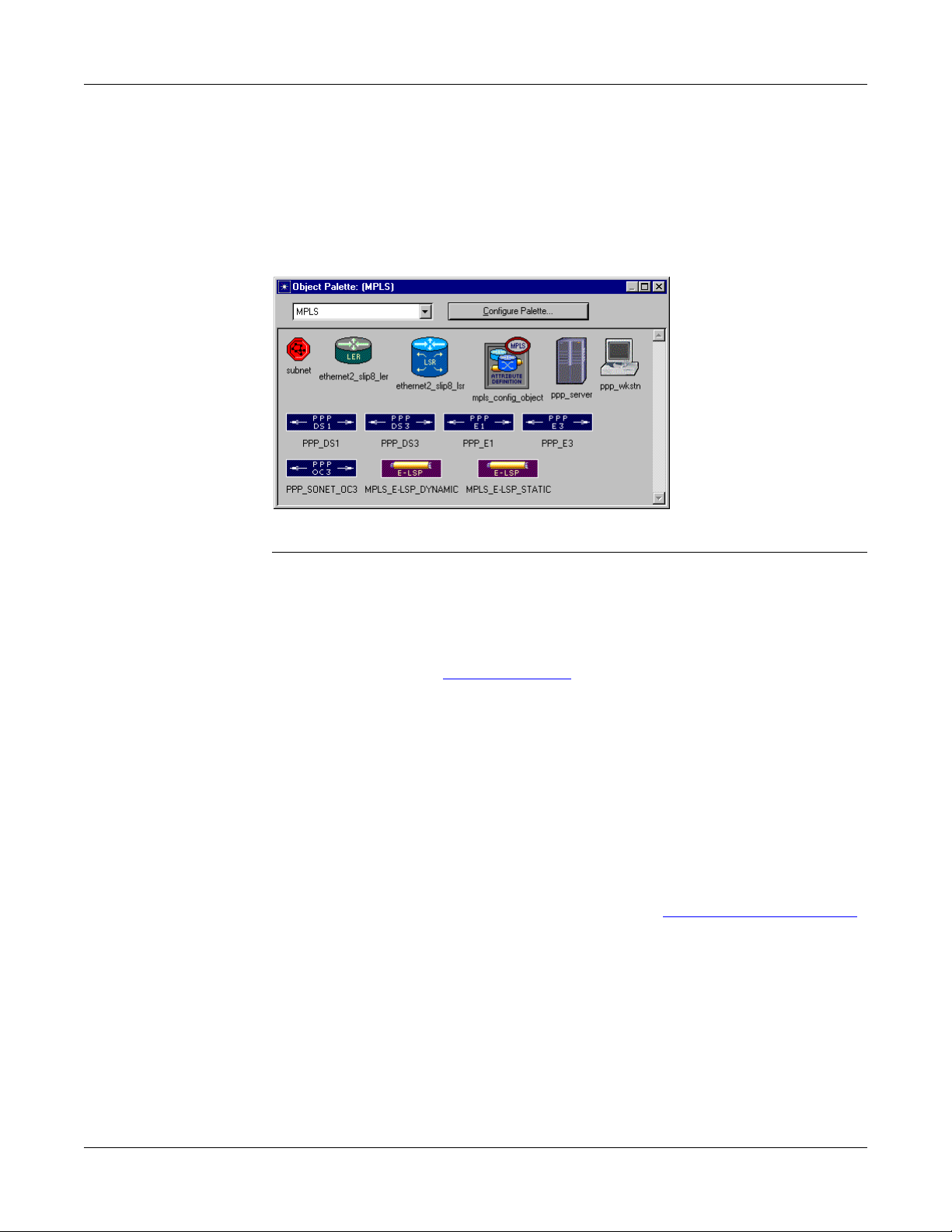
The MPLS model suite supports workstation, server, router, and link models
from the standard model libra ry. The LER (Label Edge Router) an d LSR (Label
Switching Router) node models in t he MPLS object palette are preconfigured t o
support MPLS. However, you can configure any of the router models in the
standard model library to model LERs and LSRs.
Figure 6-1 MPLS Object Palette
Model Attributes
MPLS Configuration Object Attributes
Global MPLS attributes, which are used to configure network-wide MPLS
parameters, are grouped in the MPLS configuration object. Router-specific
MPLS attributes are grouped i n the MPLS Par ameters att ribute on each router .
They are described in Router Attributes
Some of the important MPLS configuration object attributes are described
below.
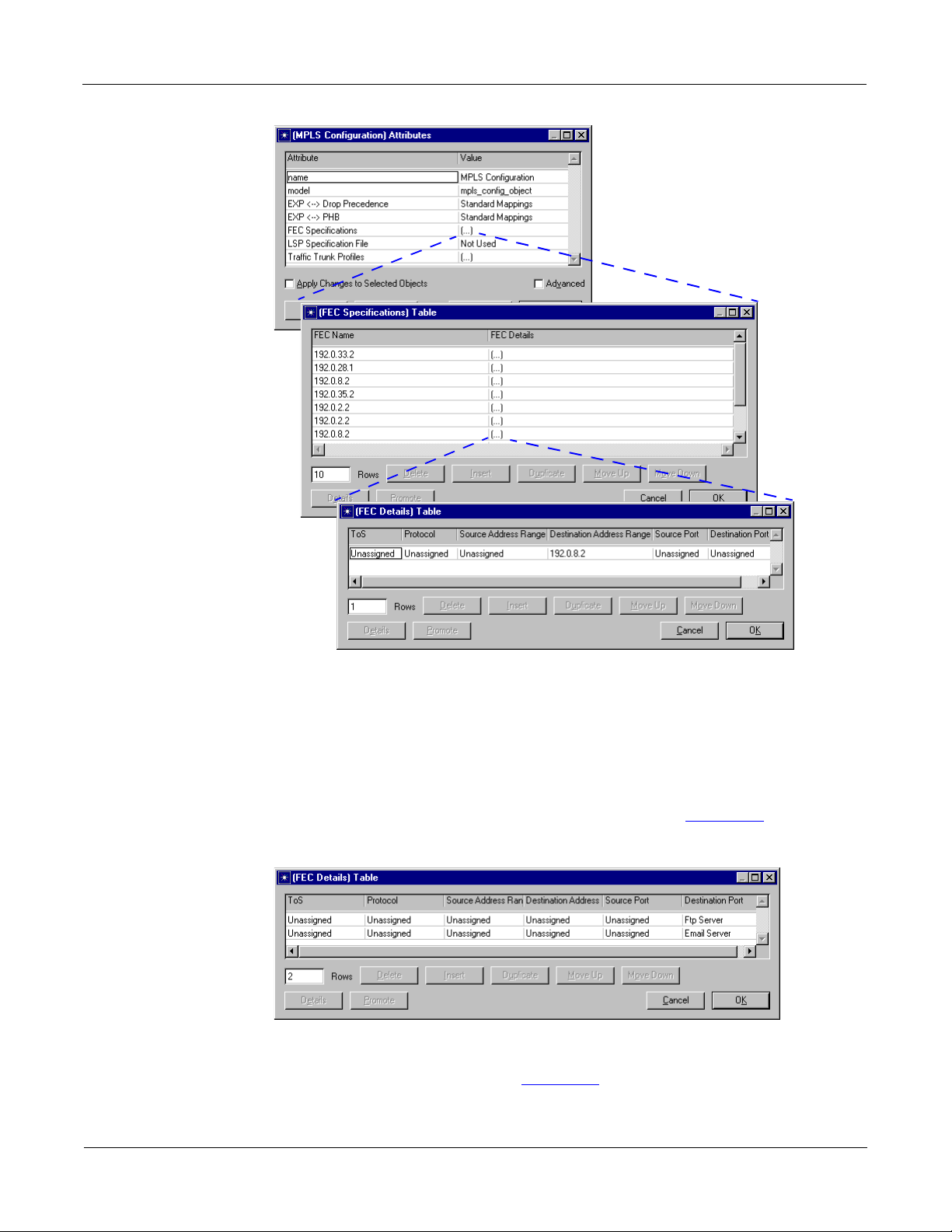
• FEC Specifications This attribute specifies the Forwarding Equivalence
Class (FEC) parameters used by MPLS in the network. FECs classify and
group packets so that all packets in a group are forwarded the same way.
FECs are based on any of the IP header fields—ToS, Protocol, Source
Address Range, Destination Address Range, Source Port, and Destinat ion
Port can all be used to define a FEC. Figure 6-2 Specifying FEC Attri butes
on page SPM-6-4 shows the attribute sequence for defining an FEC.
on page SPM-6-6.
Modeler/Release 10.0 SPM-6-3
Page 4
Specialized Models User Guide 6 MPLS Model User Guide
Figure 6-2 Specifying FEC Attributes
The FEC Details Table helps define the FEC through a set of match rules,
which are combinations of TCP, UDP, and IP header fields. FECs are
determined by taking a logical AND of the column settings in a row and by
taking a logical OR of each of the rows. In other words, for a packet to qualify
for a particular FEC, the IP header fields must satisfy every condition of at
least one row of the defined FEC. For example, a FEC that consists only of
email and ftp traffic would be specified as shown in Figure 6-3
Figure 6-3 FEC Details for E-mail and FTP Traffic
.
Therefore, if the IP header of a pac ket contained either email or FTP, it would
qualify for the FEC defined in Figure 6-3
, and would be sent over the
corresponding LSP.
SPM-6-4 Modeler/Release 10.0
Page 5
Specialized Models User Guide 6 MPLS Model User Guide
• LSP Specification File This attribute indicates whethe r the network LSPs
should be configured according to the text file specified. You can update the
text file by clicking OK in the LSP Browser. Updating the fil e recreates the file
based on the current network LSP settings, including LSPs that might not
have been in the original file (such as those created manually).
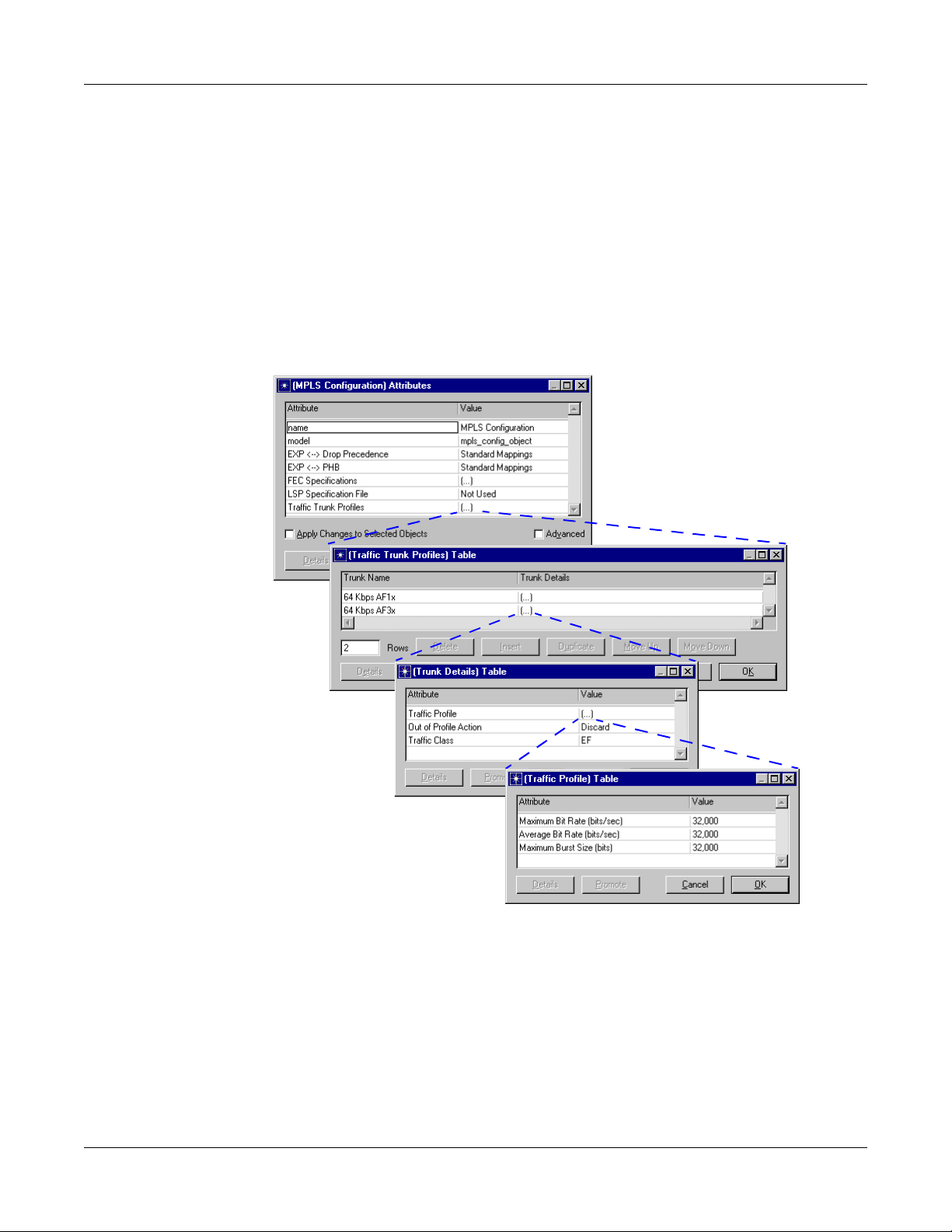
• Traffic Trunk Profiles This attribute specifies out-of-profile actions and
traffic classes for traffic trunks in the network. Traffic trunks capture traffic
characteristics such as peak rate, aver age rate, and average burst size. The
default Trunk Details setting configures a trunk with a value of
32,000 bits/sec for maximum and average bit rate and 32,000 bits for
maximum burst size.
Figure 6-4 Specifying Traffic Trunk Profiles
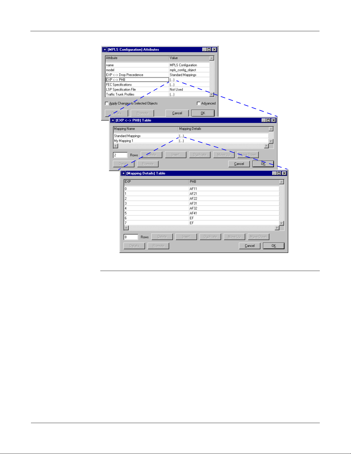
• EXP <--> Drop Precedence and EXP <--> PHB These attributes specify
how EXP bits in the MPLS shim header are translated into diffserv
information at each LSR. For E-LSPs, LSRs determine Per Hop Behavior
(PHB), while on L-LSPs, they determine Drop Precedence. Use the default
setting unless you are analyzing the effects of QoS.
Modeler/Release 10.0 SPM-6-5
Page 6
Specialized Models User Guide 6 MPLS Model User Guide
Figure 6-5 Mapping EXP Bits to Drop Precedence and PHB
Router Attributes
Some of the important MPLS Parameters attribu tes set on routers are described
below.
Traffic Mapping Configuration
This attribute specifies bindings between FECs and LSPs. Each row of the
Traffic Mapping Configuration table specifies a distinct traffic eng ineering (TE)
binding. Each TE binding specifies the FEC, traffic trunk, and LSP that is applied
to the label of the incoming packet.
Only previously defined values appear in the attribute pull-down lists. If no
values appear in the attribute pull -down lists, verify that you have defined the
FECs and traffic trunks in the MPLS Configuration objec t, and that the LSPs
appear in the network path browser.
SPM-6-6 Modeler/Release 10.0
Page 7
Specialized Models User Guide 6 MPLS Model User Guide
When an unlabeled packet arrives at an ingress LER, the following sequence
occurs to determine the correct la bel for the packet:
1) The TE binding is selected based on the packet FEC and the incoming
interface.
2) The packet is checked to make sure that its traffic characteristics conform
to those specified for the TE binding’s traffic trunk.
3) The packet is labeled for and sent t hrough the primary LSP specified for the
TE binding.
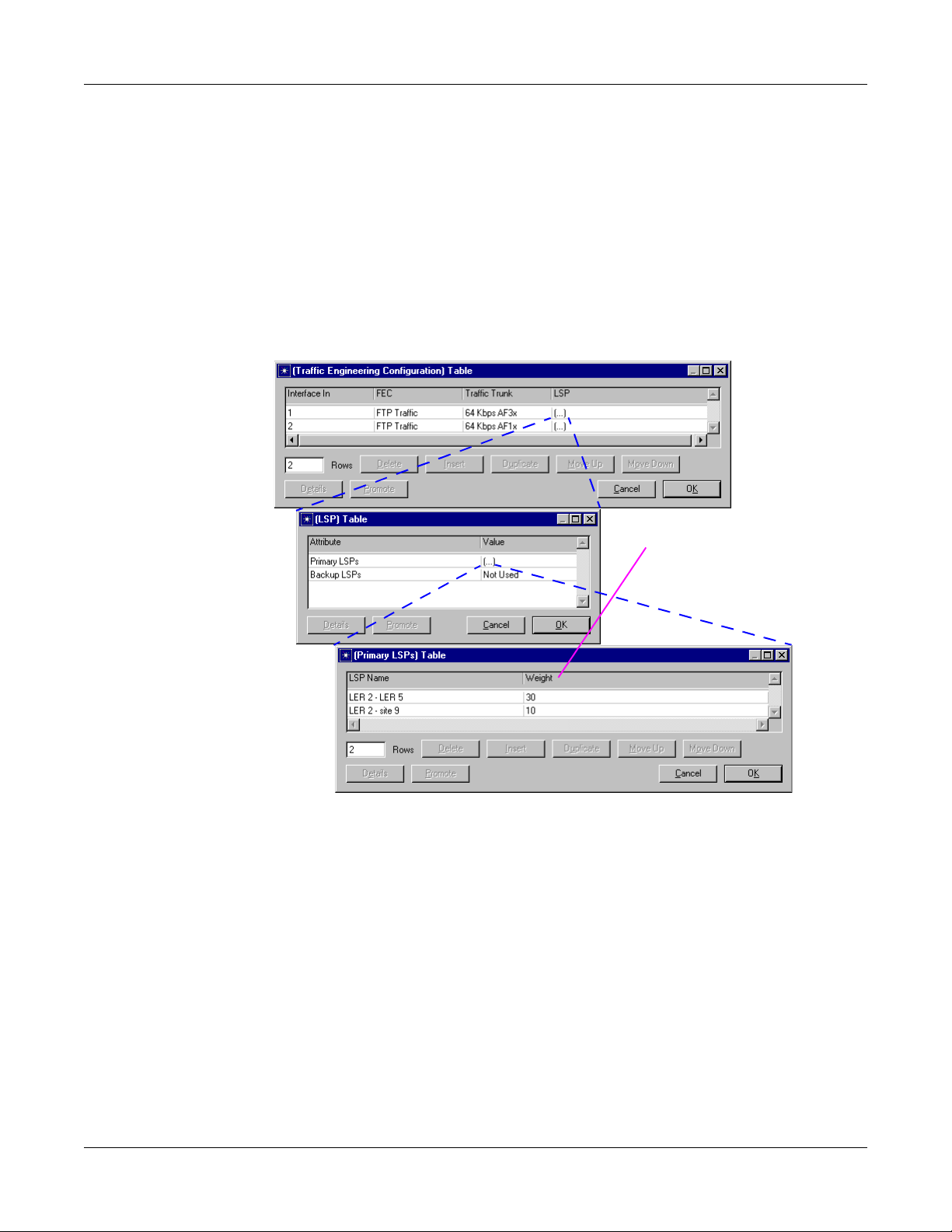
Figure 6-6 Configuring TE Bindings
\
This weight attribute
configuration uses L ER2-L ER5
75% of the time and LER2-site9
25% of the time.
• EXP <--> Drop Precedence and EXP <--> PHB These attributes specify
which mappings, defined in the MPLS configuration object, are used by the
router.
• LDP Parameters—specifies Label Distribution Prot ocol parameters used by
the LSR. LDP Parameters is a compound attribute, composed of the
following sub-attributes:
— Discovery Configuration—specifi es Hello message parameters
needed to learn of neighboring routers
— Session Configuration—specifies Keep-alive message parameters
used to establish LDP sessions
— Recovery Configuration—specifies how node and link fai lures are
detected
Modeler/Release 10.0 SPM-6-7
Page 8

Specialized Models User Guide 6 MPLS Model User Guide
Figure 6-7 Configuring LDP Parameters
Simulation Attributes
The following simulation attributes are avai lable (Configure/Run Discre te Event
Simulation dialog box) when using the MPLS model suite.
• CR-LDP Routing—specifies if CR-LDP routing uses CSPF or conventional
• CSPF Retry Timer—specifies how long an ingres s LER waits after detecting
• LDP Discovery End Time—specifies when LDP discovery ends. After this
• LDP Discovery Start Time—specifies when LDP starts sending discovery
• LSP Signaling Protocol—specifies whether dynamic LSPs are signaled
IGP to determine routes in loosely defined LSPs. The default value is IGP.
a node or link failure before rerouting an LSP that traverses the failed node
or link. The default value for this attribute is 45 seconds.
time, no more LDP discovery packets are sent through the network. This
value should occur after the network reaches a fi nal, constant state in the
simulation since no network topology or devic e status changes are reflected
in the LDP routing tables after LDP Discovery End Time.
packets through the network. Set this attribute to a value other than Do Not
Start to enable LDP.
using CR-LDP (constraint-base d routed LDP) or RSVP. The d efault val ue is
CR-LDP.
SPM-6-8 Modeler/Release 10.0
Page 9

Specialized Models User Guide 6 MPLS Model User Guide
LSP Attributes
Some of the important LSP attributes are described below. Most of these
attributes can also be configured in the LSP browse r, which i s described in the
next section.
Figure 6-8 Configuring an LSP’s Attributes
• Directionality—specifies if an LSP is unidir ectional or bidirectional. Dynamic
LSPs are always unidirectional.
• LSP Type—specifies whether the LSP is of type E-LSP or L-LSP. For
E-LSP, three experimental bits in the shim header carry the Diff-Serv
information. This p rovides eight different types of servic e (TOS) per LSP. For
L-LSP, TOS information is contained in the MPLS label and all packets
traversing the link are treated equally.
• Path Details—specifies which packets use the LSP and defines how
packets are forwarded through the LSP. This attribute is automatically
configured for dynamic LSPs. To configure this att ribute for static LSPs,
select Update LSP Details from the Protocols > MPLS menu.
Figure 6-9 Path Details for a Static LSP
• Recovery Parameters—specifies recovery parameter s that are used to
reroute traffic on this LSP if there is a link or node failure along the LSP.
Modeler/Release 10.0 SPM-6-9
Page 10

Specialized Models User Guide 6 MPLS Model User Guide
Figure 6-10 Recovery Parameters Configuration
• Setup Parameters—specifies the duration of the LSP.
Figure 6-11 Setup Parameters Configuration
• TE Parameters—specifies the traffic engineering constraints used by
CR-LDP to find a route through the network. CR-LDP uses Constrained
Routing to find the route that is t he best fi t for t he specif ied cons tr aints. Thi s
attribute applies to dynamic LSPs only. Make sure you account for network
bandwidth availability when configuring static LSPs.
Figure 6-12 TE Parameters Configuration
SPM-6-10 Modeler/Release 10.0
Page 11

Specialized Models User Guide 6 MPLS Model User Guide
LSP Browser
After you create the LSPs in the network, you may want to edit or view the
default settings. You do t his in the LSP browser , which you can access from the
Protocols > MPLS > Browse/Edit LSP Information... menu item. The browser
enables you to
• Set the hop type of LERs
• Set the start and end times for the LSP
• Set threshold values for bandwidth, del ay, and hop counts in the LSP
• Hide some or all of the LSPs from view in the Project Editor workspace
• Export LSP configuration details to a file
Figure 6-13 Using the LSP Browser
This column indicates if the
attribute values shown are
from the GUI or the LSP
specification file.
Clicking here toggles the display
settings—the workspace is immediately
refreshed to show or hide the LSPs.
These attributes set the
LSP’s Path Details and
Setup, TE, and Recovery
Parameters attributes.
Clicking OK saves the current settings in
the LSP specification file or creates this
file if one does not yet exist.
Modeler/Release 10.0 SPM-6-11
Page 12

Specialized Models User Guide 6 MPLS Model User Guide
Available Statistics
To analyze MPLS performance, you can collect path statistics on end-to-end
delay, utilization, and the amount of traffic on the LSP. These statistics can be
collected on a per-flow or per LSP basis, where flows are indivi dual flows of
traffic within an LSP.
Figure 6-14 Selecting Statistics to Collect
When analyzing your MPLS network, you may also want to look at the routes
used for the LSPs. You can do this by selecting the Protocols > MPLS >
Display LSP Routes... menu item.
SPM-6-12 Modeler/Release 10.0
Page 13

Specialized Models User Guide 6 MPLS Model User Guide
Configuring MPLS in a Network
Configuring MPLS in a network is a three-step process. Before you can run a
simulation using MPLS, you must
1) Create LSPs in the network topology
2) Create FECs and traffic trunks in the MPLS Configuration object
3) Configure LERs to direct packets into the appropriate LSPs
After this basic configuration is in place, you can add QoS/differentiated
services (DiffServ) constr aints or traffic shaping parameters.
Creating LSPs
After you create your network topology, you can add LSPs to the network. There
are three methods of adding LSPs to your network:
• From traffic conversation pairs
• By drawing the LSPs in the Project Editor workspace
• From text file s
The Update LSP Details operation creates traffic prof iles and forward
equivalence classes (FECs) for the LSPs, which you can modify later as you
fine-tune your model.
The model supports both static and dynamic LSPs using the strict and loose
path objects in OPNET. To create LSPs, use the standard procedure for
creating paths as described in the Buildi ng Models chapter of the User Guide
manual (Guru product documentation) or the Communication Mechanisms
chapter of the Modeling Concepts manual (Modeler documentation).
You can create dynamic LSPs automatic ally using the Create LSPs From Traffi c
Conversation Pairs utility or manually using the standard pr ocedure for creati ng
path objects.
The Create LSPs From Traffic Conversation Pairs utilit y creates LSPs quickly
based on some or all of the traffic conversation pairs in the network.
Procedure 6-1 Creating Dynamic LSPs from Demands
1 From the Protocols > MPLS menu, choose Configure LSPs from Demands.
➥The Assign IP Addresses dialog box appears.
Modeler/Release 10.0 SPM-6-13
Page 14

Specialized Models User Guide 6 MPLS Model User Guide
2 If you have not assigned IP addresses to all connected interfaces in the network,
click the “Perform Auto-Assignment” button. Otherwise, click the “Skip
Auto-Assignment” button.
➥The MPLS Configuration dialog box opens.
This box shows all the traffic pairs configured in the network with suggested
configuration for LSP configuration.
3 In the MPLS LSP Configuration dialog box, specify which traffic conversation pairs
should not generate LSPs by changing their Create LSP? fields to “No”.
4 Verify that the LSP configuration is correct for each LSP you would like to create.
5 Click the Export To Network button to create the LSPs in the network.
➥The LSPs appear in the network
End of Procedure 6-1
To create dynamic LSPs manually, you must speci fy the end points (ingress and
egress LERs) of the LSP. You can also specify one or more i ntermediate routers
or links along the path. When a specific link is selected for the LSP path, that
hop is marked as strict and the LSP is always set up through that li nk. Use thi s
method to indicate that certain routers or links must be used when routing
packets in an LSP. If a node or link on a dynamic LSP’ s route fails, the ingress
LER automatically tries to find an alterna te rout e. However, if the failed link or
node is marked as strict, the entire LSP fail s and the ingress LER diverts
packets to the backup LSP, if one exists.
Procedure 6-2 Creating Dynamic LSPs Manually
1 Click on the MPLS_E-LSP_DYNAMIC object in the MPLS object palette.
2 In the project workspace, click on the LSP’s ingress LER.
3 If the LSP must use certain routers or links, click on the intermediate routers or links
that must be used. Be sure to click on the objects in the same order that they occur
in the LSP.
4 Click on the LSP’s egress LER.
5 Double-click in the project workspace to finish drawing the LSP.
6 If you are finished creating dynamic LSPs, right-click in the project workspace and
select Abort Path Definition to exit path definition mode. Otherwise, draw the next
dynamic LSP.
End of Procedure 6-2
SPM-6-14 Modeler/Release 10.0
Page 15

Specialized Models User Guide 6 MPLS Model User Guide
Constrained OSPF (CSPF) is used to implement constraint-based routing of
LSPs. You can configure dynamic LSPs to use constraint-based routing in the
LSP’s TE Parameters attribute by setting the Bandwidth, Del ay, and Hop Count
constraints. When using TE constraints, the model must be configured to use
(CSPF) as follows:
• The CR-LDP simulation attribute must be set to CSPF
• The IP routing protocol must be set to OSPF (You can set the dynamic
routing protocol to OSPF using the IP Dyna mic Routing Protocol simulation
attribute.)
With static LSPs, you can specify the exact r oute used by the LSP. Static LSPs
allow more routing control, but offer le ss resiliency to node and link fail ures. For
this reason, you should always specify at least one backup route when
configuring static LSPs in your network.
Procedure 6-3 Creating Static LSPs
1 Click on the MPLS_E-LSP_STATIC object in the MPLS object palette.
2 In the project workspace, click on the LSP’s ingress LER.
3 Click on the next link or router in the LSPs route.
➥The tooltips indicate which links and routers can be added to the route. Hold the
cursor over a link or router for details about adding it to the LSP.
4 Continue clicking on each link or router in the route until all have been added.
5 Right-click in the project workspace and select Finish Path Definition to finish
drawing the LSP.
6 If you are finished creating static LSPs, right-click in the project workspace and
select Abort Path Definition. Otherwise, draw the next static LSP.
7 From the Protocols > MPLS menu, choose Update LSP Details to configure label
switching information on the LSP(s).
End of Procedure 6-3
Modeler/Release 10.0 SPM-6-15
Page 16

Specialized Models User Guide 6 MPLS Model User Guide
Creating FECs and Traffic Trunks
The traffic engineering bindings that govern how packets are labeled and
forwarded in a network use FECs and traffic trunks to classify packets. All of the
FECs and traffic trunks in a network are defined in the MPLS confi guration
object.
Procedure 6-4 Creating FECs
1 Place an MPLS configuration object in the project workspace and open its
Attributes dialog box.
2 Double-click on the value for FEC Specif ications.
➥The FEC Specifications Table appears.
3 Change the Rows value to the number of FECs you want to create.
4 For each FEC, assign a name, then double-click in the Details column to describe
the FEC.
End of Procedure 6-4
To work correctly, the model r equire s t hat you se t up at le ast one defaul t traff ic
trunk. Additional trunks can be used to handle prioritized flows.
Procedure 6-5 Creating a Default Traffic Trunk
1 Place an MPLS configuration object in the project workspace and open its
Attributes dialog box.
2 Double-click on the value for Traffic Trunk Profiles.
➥The Traffic Trunk Profiles Table appears.
3 Change the Rows value to 1.
4 Specify a name for the trunk, such as Default Traffic Trunk.
5 Leave the Trunk Details attribute as “Default”.
End of Procedure 6-5
This procedure can be modified to set up separate trunks for traffic of different
priorities. To do thi s, doubl e-c lick on th e Trunk Deta il s attr i bute and spec if y the
appropriate values for each traffic trunk .
SPM-6-16 Modeler/Release 10.0
Page 17

Specialized Models User Guide 6 MPLS Model User Guide
Creating TE Bindings on LERs
After you create the LSPs, FECs, and traffic trunks, you can cre ate TE bindings
that govern which packets are sent to which LSPs. You do this in the LER’s
MPLS Parameters
Procedure 6-6 Creating a TE Binding
1 Open the LER’s Traffic Mapping Configuration attribute dialog box (MPLS
Parameters ➘ Traffic Mapping Configuration).
2 Add a row to the table.
3 Click in the “Interface In” column and specify which interfaces the binding applies
to in the Interface Binding Specification table. To select an interface, click in the
Apply Binding column for that interface to toggle the value to “Yes.”
➥The interface(s) you selected appear in the Traffic Mapping Configuration dialog
box. Note that the interface number for higher layers corresponds to the router’s
loopback interface.
4 Select a FEC for the binding from the FEC pull-down menu.
➘ Traffic Mapping Configuration attribute.
5 Select a traffic trunk for the binding from the Traffic Trunk pull-down menu.
6 Click in the LSP column to specify the primary and backup LSPs.
End of Procedure 6-6
Modeler/Release 10.0 SPM-6-17
Page 18

Specialized Models User Guide 6 MPLS Model User Guide
Exporting LSP Configuration Details for Use in Other Scenarios
You can reuse LSPs that you have conf igured elsewher e b y export ing t he LSP
configuration details to an ASCII fil e an d using this file to create LSPs in the
network.
Procedure 6-7 Exporting LSP Configuration to an ASCII File
1 From the Protocols > MPLS menu, choose Browse/Edit LSP Information....
➥The LSP Browser appears.
2 Click Export to export the LSP configuration for all LSPs to a file.
➥The Output File Name dialog box appears.
3 Specify a name for the file.
4 Click OK to perform the export.
➥The file is saved in the primary models directory.
5 Click Cancel to close the LSP Browser.
End of Procedure 6-7
The exported file contains th e attribute sett ing s of all LSPs in t he network. You
can use the file as is in other scenarios, or you can modify the file to add,
remove, or change LSPs. Notice that the LSP configuration file closely
resembles the Path Details table for each LSP.
Procedure 6-8 Using an LSP Configuration File in a Scenario
1 Open the MPLS Configuratio n object’ s Attr ibute s dia log box.
2 Select the LSP configuration file you wish to import from the LSP Specification File
pull-down menu.
3 Click OK to close the Attributes dialog box.
➥The LSPs are added to the scenario. By default, LSPs from files are not
displayed in the network. To display these LSPs, open the LSP browser and set
their Display attributes to Yes.
End of Procedure 6-8
If you are using an LSP configurat ion file in you r network, any changes to LSPs
that you make in the LSP browser are subsequently writt en to the configuration
file when you click OK to close the browser.
SPM-6-18 Modeler/Release 10.0
Page 19

Specialized Models User Guide 6 MPLS Model User Guide
Applying QoS to an MPLS Network Model
Differential Services (DiffS erv) extensions can be used to apply
quality-of-service const raints to your MPLS network model. To do this, you must
configure QoS do the following:
• Specify traffic classes in the MPLS configuration object
• Adjust DSCP settings in the QoS configuration object
• Configure queuing schemes and profiles on the affected routers
To use different traffic classes in your MPLS network, you must first specify
separate traffic trunks f or the different clas ses in the MPLS configuration obj ect.
To do this, use Procedure 6-5
trunk. However, instead of setting the Trunk Detai ls attribute to Default,
double-click to set the traffic profile, out-of-profile actions, and traffic class of
each trunk.
on page SPM-6-16 to create a default traffic
To configure quality-of -service parameters, edit the Priority Queuing Profiles
DSCP Based attribute in the QoS configuration object.
Finally, you must configure the affected routers to use the correct queueing
scheme and queuing profile.
Procedure 6-9 Configuring the Queuing Stream and Profile of a Router
1 Set the Queuing Scheme attribute (IP Routing Parameters ➘ Interface
Information ➘ QoS Information)
2 Set the Queuing Profile attribute to DSCP Based.
End of Procedure 6-9
➘
Modeler/Release 10.0 SPM-6-19
Page 20

Specialized Models User Guide 6 MPLS Model User Guide
If you change the queuing scheme late r, make sure you reset the queuing pr ofile
because the order of these steps is important.
Figure 6-15 Configuring QoS on an LER
Always set the Queuing
Scheme before setting
the Queuing Profile.
SPM-6-20 Modeler/Release 10.0
Page 21

Specialized Models User Guide 6 MPLS Model User Guide
MPLS Menu Operations
The Protocols > MPLS menu enables you to configure, edit, and di splay MPLS
features in the network topology. With the MPLS menu operations , you to
streamline the MPLS configuration process. Table 6-3
available from the Project Editor’s Protocols > MPLS menu.
Table 6-3 MPLS Menu Summary
Menu Item Description
Update LSP Details Updates all static LSPs with label switching
information.
Configure LSPs from Demands Creates dynamic LSPs between all traffic flows.
Browse/Edit LSP Information... Opens the LSP browser.
Import LSP Information... Imports LSP information from files.
Display LSP Routes... Displays the routes chosen by CR-LDP. Does not
display lin k statistic information.
Hide all LSP Routes... Hides LSP route display.
lists the operations
Show All LSPs Displays hidden LSPs in the workspace. This
operation does no t display LSPs which are con figured
only in the LSP configuration file. To display those
LSPs, use the display functions in the LSP browser.
Hide All LSPs Hides LSPs displayed in the project workspace from
view.
Clear All LSPs Deletes all LSPs in the network and resets the traffic
mapping configuration.
Deploy MPLS VPNs
Configure Interface Status Enables/disables MPLS protocol status on either
selected or all routers.
Model User Guide Opens this document.
End of Table 6-3
Modeler/Release 10.0 SPM-6-21
Page 22

Specialized Models User Guide 6 MPLS Model User Guide
Information for OPNET Modeler Users
The rest of this document contains inf o rmation for model developers (such as
OPNET Modeler users). The following sections describe the topics necessary
for understanding the internal det ails of and interfacing to the MPLS model.
Model Architecture
Each node that can use MPLS has an IP module, which contains a dispatcher
process that spawns MPLS processes. The following table lists the process
models used by the MPLS model.
Table 6-4 MPLS Process Models
Process model Description
mpls_mgr One instance of this process is spawned by ip_dispatch on
each MPLS enabled node in the network. It represents the
forwarding component of MPLS and the forwarding control
plane.
When the IP module of an LSR receives labeled packets or
packets with matching FEC descriptions, it performs no IP
processing on the pa ck et. Inst ead , the p ack et is re-directed to
the mpls_mgr process for MPLS forwarding.
mpls_mgr uses ILM (incoming label map) and FTN (FEC to
NHLFE maps) to forward packets.
mpls_ldp_mgr Implements the LDP control plane in the LDP module of all
routers. This process is the dispatcher for the
mpls_discovery_mgr, mpls_session_mgr, and mpls_lsp_mgr
processes.
mpls_discovery_mgr Sends periodic broadcast hello messages over UDP to
discover MPLS-enabled neighbor routers.
mpls_session_mgr Negotiates, opens, an d maintains TCP sessions to neighbori ng
LDP routers. The TCP sessions are used to exchange label
maps. This process is based on RFC 3036.
mpls_lsp_mgr Controls the exchange-to-label mapp ings betwee n LDP peers.
Communication with LDP peers occurs through the session
established by the mpls _session_mgr pro cess. This process is
based on RFC 3036.
End of Table 6-4
SPM-6-22 Modeler/Release 10.0
 Loading...