

Page 1

6400i Line Matrix Printers
Setup Guide
Cabinet and Pedestal Models
S544-5640-04
Page 2

Page 3

6400i Line Matrix Printers
Setup Guide
Cabinet and Pedestal Models
S544-5640-04
Page 4

Note!
Before using this information and the product it supports, read the information in “Notices” on
page 329.
Fifth Edition (May 2003)
This edition replaces S544-5640-03.
Requests for IBM
to the IBM branch office serving your locality. If you request publications from
the address given below, your order will be delayed because publications are
not stocked here. Many of the IBM Printing Systems Division publications are
available from the web page listed below.
®
publications should be made to your IBM representative or
Internet
Visit our home page at: http://www.ibm.com/printers
A Reader’s Comment form is provided at the back of this publication. If the
form has been removed, you can send comments by fax to 1-800-524-1519
(USA only) or 1-303-924-6873; by E-mail to printpub@us.ibm.com; or by mail
to:
IBM Printing Systems Division
Department H7FE Building 004M
Information Development
PO Box 1900
Boulder CO 80301-9191 USA
IBM may use or distribute whatever information you supply in any way it
believes appropriate without incurring any oblication to you.
© Copyright International Business Machines Corporation 2003. All
rights reserved.
US Government Users Restricted Rights – Use, duplication or disclosure
restricted by GSA ADP Schedule Contract with IBM Corp.
Page 5

Safety Noti ces
DANGER:
<1> Before powering on the printer ensure the printer is plugged
into an appropriate power source. Refer to Chapter 2 of the
Setup Guide for information on the proper source.
<2> Switch off the printer power and unplug the printer power
cord before cleaning the printer.
<4> Do not connect or disconnect any communication port,
teleport, attachment connector, or power cord during an
electrical storm.
<5> Power off the printer and disconnect the power cord before
connecting or disconnecting any communication port,
teleport, or attachment cable connector.
CAUTION:
This product is equipped with a 3-wire power cord and plug for the user’s safety. Use this power
cord in conjunction with a properly grounded electrical outlet to avoid electrical shock.
Page 6

Page 7

Table of Contents
1 Introduction........................................................... 13
About This Setup Guide..........................................................................13
Notes And Notices ....................................... ...... ....... ...... ....... ...... ....13
Conventions In This Setup Guide ....................................................14
Related Documents..........................................................................15
The IBM 6400 Printer Family..................................................................16
Standard Capabilities.......................................................................18
Optional Features.............................................................................21
Protocols And Emulations................................................................23
Graphics Enhancements..................................................................23
Taking Care Of Your Printer.............................................................23
2 Installation............................................................. 25
Installation, Attachment, And Configuration Overview............................25
Before You Begin....................................................................................27
Power Requirements ..............................................................................27
Select A Site ...........................................................................................28
Printer Dimensions .................................................................................29
Printer Component Locations.................................................................31
Remove Shipping Restraints (Cabinet Model)........................................33
Remove The Cardboard Packing And Envelope..............................34
Remove The Hammer Bank Protective Foam..................................35
Remove The Platen Protective Foam ..............................................37
Remove Wood Blocks......................................................................38
Adjust The Paper Supports..............................................................39
Release The Paper Chains (Cabinet Model)....................................40
Remove Tags (Cabinet Model) ........................................................41
Remove The S hipping Restraints From
The Power Paper Stacker ................................................................42
Removing Shipping Restraints (Pedestal Model)...................................44
Remove The Hammer Bank And Protective Foam..........................45
Remove The Platen Protective Foam ..............................................46
Attach The Input Paper Shelf and Output Basket ............................47
Remove Tags - Pedestal Model.......................................................48
Page 8

Table of Contents
Changing the Paper Exit Location
(Pedestal Models Only) ..........................................................................49
Setting Top Paper Exit .....................................................................49
Setting Rear Paper Exit....................................................................51
Connect The Interface And Power Cables (Cabinet Models).................52
Connect The Interface And Power Cables (Pedestal Models) ...............58
Attach The Operator Panel Overlay Label..............................................62
Install The Ribbon............................ ...... ...... ....... ....................................63
Load The Paper......................................................................................66
Power Paper Stacker Option..................................................................72
Power Paper Stacker Component Locations ...................................72
Setting Up The Power Paper Stacker ..............................................73
Loading And Starting The Power Paper Stacker .............................74
Checking The Paper Feed......................................................................75
Set The Top-of-Form ..............................................................................77
Test The Printer......................................................................................78
3 Configuring the Printer..........................................79
Overview.................................................................................................79
The Configurations...........................................................................79
Active Versus Saved Configurations................................................80
The Configuration Main Menu ................................................................80
Using The Operator Panel......................................................................83
Program Mode........................................................................................84
Unlocking The Program Mode .........................................................84
Locking The Program Mode.............................................................84
Entering Program Mode ...................................................................85
Printing The Current Configuration.........................................................85
Factory Default Configuration Values.....................................................87
Changing Parameters.............................................................................92
Saving Your Configuration In A Custom Set...........................................94
Loading Custom Sets Or Factory Default Values...................................97
Changing The Power On Configuration..................................................99
4 The Configuration Menus............................... .....103
Configuration Overview ........................................................................103
Main Menu............................................................................................104
Printer Control Menu.............................................................................106
Configuration Management Menu ........................................................113
Twinax Interface Menu .........................................................................117
Coax Interface Menu ............................................................................126
Compatibility Options Menu .................. ....... ...... ....... ...... ....... ...... ..135
Page 9

Table of Contents
5250 Interface Menu.............................................................................139
3270 Interface Menu.............................................................................145
Compatibility Options Menu ...........................................................151
Network Setup Menu ............................................................................155
Adapter Address Submenu............................................................155
Adapter Parameters Submenu.......................................................157
Ethernet Address Submenu...........................................................161
Ethernet Parameters Submenu......................................................162
Wireless Address Menu .................................................................165
Wireless Parameters Menu............................................................166
Parallel Interface Menu.........................................................................170
PC Parallel Menu ...........................................................................172
Dataproducts Menu........................................................................175
IEEE 1284......................................................................................178
Serial Interface Menu............................................................................180
Emulation Configuration Menu .............................................................186
IPDS Feature........................................................................................187
IPDS Configuration Menu ..............................................................188
ANSI...............................................................................................195
IGP Feature (PGL)................................................................................203
IGP Emulation Menu ......................................................................204
Code V Feature (VGL)..........................................................................209
Code V Emulation Menu ................................................................210
Printer Emulation Configuration Menu..................................................219
Proprinter III XL Emulation Menu...................................................220
Epson Emulation Menu ..................................................................222
P-Series Emulation Menu...............................................................224
P-Series XQ Emulation Menu ........................................................228
Serial Matrix Emulation Menu ........................................................231
Print Format Menu .........................................................................234
Operator Print Tests Menu ...................................................................242
Printer Information Menu......................................................................244
RibbonMinder Menu .............................................................................245
Page 10

Table of Contents
5 Printer Inter fa ces............... .. ............................. .. .24 9
Overview...............................................................................................249
RS-232 And RS-422 Serial Interfaces..................................................250
RS-232...........................................................................................250
RS-422...........................................................................................251
RS-232 Serial Interface Protocols..................................................252
RS-232 and RS-422 Serial Interface Protocols..............................252
RS-232 and RS-422 Serial Interface Error Handling .....................253
RS-232 and RS-422 Serial Interface Configuration .......................253
PC Parallel Interface.............................................................................254
PC Parallel Interface Signals .........................................................255
PC Parallel Interface Configuration................................................256
Dataproducts Parallel Interface ............................................................257
Dataproducts Parallel Interface Signals.........................................258
Dataproducts Parallel Interface Configuration ...............................258
IEEE 1284 Parallel Interface.................................................................259
Operating Modes............................................................................259
The Negotiation Phase...................................................................260
Signals ...........................................................................................260
Terminating Resistor Configurations..............................................263
6 Routine Service and Diagnostics........................265
Overview...............................................................................................265
Cleaning Requirements ...................................... ...... ............................265
Cleaning The Outside Of The Cabinet...........................................265
Cleaning Inside The Cabinet..........................................................266
Printer Self –Tests ................................................................................269
Running The Printer Self–Tests............................................................270
Hex Code Printout ................................................................................271
Fault Messages ....................................................................................275
Fault Correction Procedure ............................................................275
A Printer Specif ica tion s ............... .. ... ................ ......289
Ribbon Specifications...........................................................................289
6400i Models Except 6400-i20 and -i24.........................................289
6400-i20 and i24 Models................................................................289
Ordering Ribbons..................................................................................290
6400-ixx Models.............................................................................290
Paper Specifications.............................................................................291
Paper..............................................................................................291
Labels.............................................................................................292
Page 11

Table of Contents
Printer Dimensions and Weight ............................................................292
Cabinet Models ..............................................................................292
Pedestal Models.............................................................................292
Environmental Characteristics..............................................................293
Temperature...................................................................................293
Relative Humidity ...........................................................................293
Acoustic Noise Level......................................................................293
Electrical Characteristics ......................................................................294
Input Voltage..................................................................................294
Power Consumption.......................................................................294
Interfaces..............................................................................................297
Cables...................................................................................................297
Printing Rates .......................................................................................298
B A Quick Look at Line Matrix Printing................... 301
Character Formation................. ...... ....... ...... ....................................... ..301
Printing Speed ......................................................................................303
C Host Attachment ................................................. 305
Host Attachment ...................................................................................305
Compatibility and Limitations................. ...... ....... ...... ....... ...... ....... ........306
Compatibility...................................................................................306
Limitations......................................................................................308
D Attaching Host Syst ems to a
Coax/Twinax Printer............................................ 311
Attaching Printer to an iSeries or zSeries Host System........................311
Attaching Printer to an iSeries Host System.........................................311
Attaching Printer to an iSeries with Twinax Interface.....................311
Changing Your iSeries Printer Configuration .................................312
Attaching Printer to Remote Control Unit with Twinax Interface ....314
Attaching Printer to an IBM System/36 with Twinax Interface........315
Attaching Printer to zSeries Systems ...................................................316
Types of Installation covered for MVS/JES2..................................316
6400-LU1-SCS-Local SNA 3174 Control Unit................................316
6400-LU1-SCS-Remote SNA 3174 Control Unit............................318
6400-LU3-DSE-Local SNA 3174 Control Unit................................320
6400-LU3-DSE-Remote SNA 3174 Control Unit............................321
6400-LU0-DSC-Local Non-SNA 3174 Control Unit........................323
Attaching Printer to VM Host System ...................................................324
SNA Attachment.............................................................................324
Non-SNA Attachment.....................................................................325
Page 12

Table of Contents
Physical and Logical Unit Types...........................................................325
Physical Unit (PU) types and examples.........................................325
Summary of LU Types and Representative IBM Products.............326
Notices ................................................................329
Energy Star...........................................................................................329
Notices..................................................................................................329
Trademarks...........................................................................................331
Product Recycling and Disposal...........................................................332
Communication Statements................................ ...... ....... ...... ....... ...... ..333
Glossary..............................................................337
Page 13

1 Introduction
About This Setup Guide
This Setup Guide is designed so that you can quickly install and configure
your IBM 6400 printer.
Notes And Notices
For your safety and to protect valuable equipment, it is very important that you
read and comply with all information noted in the following section:
DANGER
<#> The word Danger next to the lightni ng slash ind icates the presence of a
hazard that could cause death or serious personal injury. Danger and
Caution notices are numbered to help you find the translated versions
in the IBM 6400 Safety Notices booklet.
CAUTION
<#> The word Caution next to the exclamation point (!) indicates the
presence of a hazard that could cause moderate or minor personal
injury.
CAUTION
<#> The word Caution next to this symbol indicates a part or assembly that
is hot enough to burn you.
13
Page 14

Chapter 1 About This Setup Guide
CAUTION
<#> The word Caution next to this symbol indicates a part or assembly that
is sharp enough to cut you.
The word Attention indicates the possibility of damage to a program,
device, system, or data.
The word Important indicates information vital to proper operation of
the printer.
NOTE: A note gives you helpful information and tips about printer operation
and maintenance.
ATTENTION
IMPORTANT
Conventions In This Setup Guide
Key names, indicator names, and messages that appear on the operator
panel display are capitalized as they actually appear on the printer. Key
names are shown in bold.
Example: Press the CLEAR key, then press the ON LINE key.
Quotation marks (“ ”) indicate messages on the Liquid Crystal Display (LCD).
For example:
Example: Press the ON LINE key. “OFFLINE” appears on the LCD.
14
Page 15

Related Documents
Related Documents
• Maintenance Information Manual — Explains how to maintain and repair
the line matrix printer at the field service level of maintenance.
• Coax/Twi nax Prog ramme r's Ref erenc e Manua l — Covers the host control
codes and character sets for the Coax and Twinax emulations.
• LinePrinter Plus Programmer's Reference Manual — Covers the host
control codes for the LinePrinter Plus emulation.
• IGP Programmer's Reference Manual — Provides information used with
the optional IGP emulation enhancement feature.
• Code V Programmer's Reference Manual — Provides information used
with the optional Code V
TM
emulation enhancement feature.
• ANSI Programmer's Reference Manual — Provides host control codes
and character sets for the ANSI emulation.
• IPDS Twinax Emulation Programmer's Reference Manual — Provides an
overview of Intelligent Printer Data Stream
and diagnostics.
TM
(IPDS) features, commands,
• Character Sets Reference Manual — Information about and examples of
the character sets available in line matrix printers.
• Ethernet Interface User's Manual — Informati on ab out netw ork pr ot oco ls,
configuration, and operation.
15
Page 16

Chapter 1 The IBM 6400 Printer Family
The IBM 6400 Printer Family
The IBM 6400 series consist of 500, 1000, 1500, 2000, and 2400 lines per
minute (lpm) models and are packaged in various configurations. All of the
models offer software versatility and the latest refinements in line matrix
printing technology. The print mechanisms are housed in sound-insulated
cabinets which make the printer family among the quietest printers in the
world. Additionally, your printer has a flexible architecture that allows you to
add new features and emulations as they become available.
®
LinePrinter Plus
®
Epson
Proprinter
PGL
FX-1050, Printronix® P-Series, P-Series XQ, Serial Mat rix and
®
®
and IGP/VGL graphics enhancement emulations are available as
optional upgrades. No matter what emulation is installed, your printer is easy
to use. The message display and lights on the control panel communicate
with you directly and clearly. You can select every function on your printer at
the control panel, or you can send commands from the host computer.
is the standard emulation. LinePrinter Plus includes the
III XL emulations. Coax/Twinax, IPDSTM, ANSI® and the IGP®/
The printer combines the use of Flash, RAM, and nonvolatile RAM for
program execution. The Flash is used for all program, font, and emulation
storage. New fonts, emulations, or program updates can be downloaded to
®
Flash memory via the parallel or serial interface, or through the PrintNet
interface. The RAM is used for buffers, print image storage, and execution
variables. The non-volatile RAM stores configuration, statistics, and internal
parameters.
16
Page 17

The IBM 6400 Printer Family
The printer model numbers indicate printing speed and physical configuration.
Related Documents
• All printer models start with the 6400 series prefix, followed by a three
digit or alphanumeric suffix. Models containing only numbers indicate
cabinet models. Model numbers containing the letter “P” indicate pedestal
models.
• For cabinet models, the alphanumeric suffix refers to the printer’s
maximum speed in lines per minute (lpm): i05 for 500 lpm, i10 for 1000
lpm, i15 for 1500 lpm, i20 for 2000 lpm, and -i24 for 2400 lpm.
• For pedestal models, the first two alphanumeric values in the suffix refer
to the printer’s maximum speed in lines per minute (lpm): i5P for 500 lpm
and i1P for 1000 lpm.
• The 6400-i5P and i1P models are pedestal models with the QuickAccess
Cover installe d.
• The 6400 i20, i2s, and i24 models are available with the power stacker
option installed.
Refer to the following table for a complete listing of model numbers and
options.
T a ble 1: 6400-i05, -i5P, -i10, -i1P, -i15, -i20, -i2s, i24 Printers
Model
Number
6400-i05 500 lpm X 28 Hammers
6400-i5P 500 lpm X 28 Hammers X
6400-i10 1000 lpm X 60 Hammers Available as option
6400-i1P 1000 lpm X 60 Hammers X
6400-i15 1500 lpm X 102 Hammers Available as option
6400-i20 2000 lpm X 156 Hammers Available as option
6400-i2s 2000 lpm X 126 Hammers Available as option
6400-i24 2400 lpm X 156 Hammers Available as option
Print
Speed
Cabinet Pedestal
Hammer
Bank
Quick
Access
Power Stacker
17
Page 18

Chapter 1 The IBM 6400 Printer Family
St andard Capab ilities
The 6400 printer family has the following general characteristics:
• A broad range of print speeds in both cabinet and pedestal models
• Support of similar features across the entire product line to allow
maximum flexibility in matching the printer to the requirements
• Energy Star compliant
The following sections summarize the standard capabilities of the IBM 6400
printers.
Host Computer Interfaces
• RS 232 Serial
• RS 422 Serial
• PC Parallel
• Dataproducts Parallel
• Ethernet Interface
• IEEE 1284
Coax/Twinax features are available with this printer:
• IBM Coax/Twinax
Printer Emulations
Each emulation provides a different set of configuration menus, control codes,
and character sets. The following printer emulations (or protocols) are
standard, and selectable at the operator panel:
• Proprinter III XL Emulation
• Epson FX Emulation
• P-Series Printer Emulation
• P-Series XQ Variant Printer Emulation
• Serial Matrix Printer Emulation
Proprinter III XL and Epson FX Emulations
The Proprinter III XL and Epson FX emulations are industry standard printer
emulations.
18
Page 19

Standard Capabilities
P-Series Printer Emulation
This code system was developed especially for line matrix printers. As line
matrix printers became more sophisticated, this code system kept pace by
adding codes that fully utilized line matrix printer capabilities.
IMPORTANT
This emulation appears as “P-Series” on the operator panel.
P-Series XQ Variant Printer Emulation
This code system was devised for a series of printers manufactured between
1974 and 1991, that are no longer available.
IMPORTANT
This emulation appears as “P-Series XQ” on the operator panel.
Serial Matrix Printer Emulation
This printer emulation is very similar to the code systems used by an IBM
Graphics Printer, but incorporates several systems into one emulation. This
emulation enables a line matrix printer to print files coded for a serial matrix
printer, and is sometimes referred to as the Serial Matrix collection.
IMPORTANT
This emulation appears as “Serial Matrix” on the operator panel.
NOTE: Serial matrix refers to the way printer characters are formed. A
moving printhead uses pins to form whole characters one at a time
and one after the other. The pins print dots according to programmed
matrix patterns. Data is sent to the printer through either a serial or
parallel interface, but the printhead must receive the data serially to
form each character.
An IBM line matrix printer also forms characters with dots in matrix
patterns, but it feeds print data in parallel to many hammers mounted
on a rapidly oscillating shuttle. The hammers fire simultaneously to
print entire lines at a time.
19
Page 20

Chapter 1 The IBM 6400 Printer Family
Output Control
The printers have the following output control features:
• Six modes for printing text:
• Near-Letter Quality (NLQ)
• Near-Letter Quality San Serif
• Data Processing (DP)
• Draft
• Optical Character Recognition Font A (OCR A)
• Optical Character Recognition Font B (OCR B)
OCR A and OCR B support 120 and 180 PEL, with 120 PEL the default value.
• Selectable forms length and width
• Character attribute specification:
• Selectable pitch: normal, expanded, and compressed
• Emphasized (shadow) printing
• Automatic underlining and overscoring
• Superscript and subscript printing
• Double high and wide printing
• Resident multinational cha ra cte r sets
Graphics And V ertical Form atting
Several graphics and vertical formatting features are available:
• Three built-in graphics generators:
• IBM Proprinter III XL bit-image graphics
• Epson FX dot graphics mode
• P-Series Plot
• Programmable electronic vertical formatting provides rapid vertical paper
movement to specified lines for printing repetitive and continuous forms.
You can use the following methods:
• Vertical tabbing in Serial Matrix, Proprinter III XL, and Epson FX
emulation modes
20
• Electronic Vertical Format Unit (EVFU) in P-Series emulation mode
Page 21

Optional Features
Built-in Diagnostic Tools
The following diagnostic tools are provided with the printer:
• Comprehensive diagnostic self-tests permanently stored in the printer
• Configuration printout
• Data stream hex code printout
Optional Features
The following features can be ordered and installed on this printer. If you
ordered a feature at the time of purchase, the feature may already be installed
on your printer. Refer to the documentation shipped with the feature for more
details.
For detailed information about these features or for information on ordering a
feature, contact your IBM sales representative.
• IBM Coax/Twinax Attachment:
Enables you to attach this printer to IBM host systems, such as an iSeries
or zSeries Host System. This feature also helps you to replace IBM coax/
twinax printers such as the IBM 3262 Models 3 and 13, IBM 4234 Models
1, 2, and 9, and IBM 5224 Models 1 and 2. This feature can be used with
the Intelligent Printer Data Stream (IPDS) feature which is described
below.
• IBM Intelligent Printer Data Stream Coax/Twinax:
Provides the ability to create forms, overlays, and graphics. IPDS also
provides compatibility when replacing printers such as the IBM 4234
Models 12 and 11. This feature also supports many versions of the Print
Services Facility* (PSF*). This feature requires the IBM Coax/Twinax or
Ethernet card attachment.
• Code V:
This is an implementation of the Intelligent Graphics Processor
architecture and is used commonly to create graphics for optical
character recognition and bar codes. This feature is also designed for
those applications which use the Quality Micro Systems, Inc. graphics
language, which is often referred to as the QMS Code V Magnum
emulation and those applications that use the Code V Graphics
Language. The Code V Graphics Language is often referred to as VGL.
21
Page 22

Chapter 1 The IBM 6400 Printer Family
• IGP:
This is an implementation of Intelligent Graphics Processor architecture
and is used commonly to create graphics for optical character recognition
and bar codes. This feature is also designed for those applications which
use the Graphics Language, which is often referred to as PGL.
This feature can co-exist with the IBM Intelligent Printer Data Stream
feature, and/or with either coax/twinax feature or can be used on the
ASCII models.
• Network Print Server:
Enables you to attach your printer to Local Area Networks using tokenring or Ethernet protocols. The Network Print Server functions as a
workstation server on your network, enabling your users to submit print
jobs to your printer.
The Network Print Server provides multiple network protocol support that
allows you to submit print jobs from Novell** Netware**, IBM LAN Server,
IBM AIX*, and other TCP/IP networks.
• Dataproducts Adapter:
Supplies a 50 pin AMP Amplimite HDH-20 data cable connector. This
feature is necessary if you are using the Dataproducts parallel protocol.
• Ethernet Interface:
Enables you to attach your printer to Local Area Networks using Ethernet
protocols. The Ethernet Interface functions as a workstation server on
your network, enabling your users to submit print jobs to your printer.
• Power Paper Stacker:
Mechanically directs the paper from the printer to the paper stacking area.
This feature provides consistent paper handling with fewer paper jam
errors.
• Input Paper Shelf:
Pedestal model only. Provides a shelf to hold a box of paper or forms.
This is a convenient feature if you need to move the printer often.
• TN5250/TN3270 Emula tio ns :
The TN5250/TN3270 feature enables your printer to communicate with
an IBM host through a Network Interface Card (NIC) using the 5250/3270
datastream. This feature allows you to use an application generated for
the Twinax/Coax emulation to be printed through the NIC.
22
Users who are converting from Twinax to TN5250 may see some
differences. Please refer to the “Compatibility and Limitations” on page
306 for details.
• ANSI Emulation:
The ANSI option allows you to print files coded for the ANSI (American
National Standards Institute) printer control language.
Page 23

Protocols And Emulations
Protocols And Emulations
A protocol is a set of rules governing the exchange of information between the
printer and its host computer. These rules consist of codes that manipulate
and print data and allow for machine-to-machine communication. A printer
and its host computer must use the same protocol. As used in this manual,
protocol and emulation mean the same thing.
Most impact printers are single ASCII character codes to print text, numbers,
and punctuation marks. Some characters, both singularly and in groups are
defined as control codes. Control codes instruct the printer to perform specific
functions, such as underlining text, print subscripts, setting page margins, etc.
The main difference between most printer protocols is in the characters used
to create control codes and the ways in which these characters are formatted.
When the printer executes the character and control codes of a particular
printer protocol, it is “emulating” that printer. If the printer uses the Proprinter
III XL protocol, for example, it is emulating an IBM
the printer is using the Epson FX printer protocol, for example, we can also
say it is in Epson FX emulation mode.
®
Proprinter III XL printer. If
There are additional emulations that are provided as optional features, such
the Code V and IGP emulations. For additional information, refer to “Code V
Feature (VGL)” on page 209 and “IGP Feature (PGL)” on page 203.
Graphics Enhanc ements
The PGL and Code V emulations allow you to create and store forms,
generate logos, bar codes, expanded characters, and create other graphics.
Alphanumeric and bar code data are added as the form is printed.
These emulations are available as factory-installed or field-installed options.
For more information, contact your authorized service representative.
Taking Care Of Y our Printer
Your printer will produce high print quality jobs if it is well taken care of.
Periodic cleaning, handling the printer properly, and using the correct printer
supplies such as paper and ribbons ensures optimum performance. Chapter
6 explains how to clean the printer, and printer supplies are listed in Appendix
A.
Whenever it is necessary to service the printer, remember these important
maintenance concepts:
• Use only the ribbons specified in Appendix A. Use of incorrect ribbons
can lead to ink migration problems, degraded print quality, and expensive
damage to the printer.
• Incorrect closure of the forms thickness lever can lead to smearing,
degraded print quality, paper jams, and damage to the platen and shuttle
assembly. Never close the forms thickness lever too tightly.
23
Page 24

Chapter 1 The IBM 6400 Printer Family
24
Page 25

2 Installation
Installa tion, Att achment, And Configuration Over view
Note!
Before using this information and the product it supports, read the
information in “Notices” on page 329.
DANGER
<4> Do not connect or disconnect any communication port, teleport,
attachment connector, or power cord during an electrical storm.
<5> Power off the printer and disconnect the power cord before
connecting or disconnecting communication port, teleport, or
attachment cable connector.
The following is an overview of the steps you need to complete to successfully
install, attach, and configure your printer:
1. Unpack the printer from the shipping package. Follow the instructions
provided on the shipping package.
2. Set up the printer, which includes; removing shipping materials, installing
a ribbon, and loading paper. Follow the instructions in this chapter.
3. Perform an initial print test by printing the current configuration page as
described on page 85.
4. Review the information contained in the README.1ST file on the
Configuration Utility diskette.
NOTE: The Configuration Utility diskette contains a README.1ST file that
describes the contents of the diskette, AIX print drivers, and
configuration information for replacing existing IBM printers. In
addition, there might be another file, called README.TXT that
contains information that was added after the printer documentation
was printed.
25
Page 26

Chapter 2 Installation, Attachment, And Configuration Overview
5. Attach the printer to the host system and configure the host system to
work with the printer.
a. For ASCII attachments, follow the instructions in the 6400 ASCII
Programmer’s Reference Manual.
b. For Coax/Twinax attachments, follow the instructions in the 6400
Coax/Twinax Programmer’s Reference Manual.
c. If you have ordered the Network Print Server feature, follow the
instructions in either the Network Print Server Ethernet
Administrator’s Guide, or the Network Print Server Token-Ring
Administrator’s Guide.
d. If you have ordered the Ethernet Interface, follow the instructions in
the Ethernet Interface User’s Manual.
NOTE: If you are attaching this printer to an AIX host system, use the AIX
Version 3.2.5 and 4.1 print drivers provided on the Configuration
Utility diskette.
6. If you have not already ordered a communications cable, see page 297.
7. Configure the printer to work with host systems and to match your
emulation, such as IBM Proprinter III XL. Follow the instructions provided
in Chapter 3, “Configuring the Printer” and review the information
provided in Appendix C, “Host Attachment.”
NOTE: If you are replacing an printer with this printer, make sure you review
the information on the Configuration Utility diskette. The
Configuration Utility diskette contains information that will help you
configure this printer to match the configuration of the printer you are
replacing.
8. Install and/or configure optional features by following instructions
provided in the appropriate feature manual. For a brief description of the
following optional features, refer to: “IPDS Feature” on page 187, “Code V
Feature (VGL)” on page 209, and “IGP Feature (PGL)” on page 203.
NOTE: For more detailed information about any optional feature, refer to the
manual that was shipped with the feature. If you want to order a
manual to learn more about these features, see “Related Documents”
on page 15.
26
Page 27

Before You Begin
Read this chapter carefully before installing and operating the printer. The
printer is easy to install. However, for your safety and to protect valuable
equipment, perform all the procedures in this chapter in the order presented.
Make sure you have a way to move the printer and shipping pallet. You
will need a jack.
Make sure you have adequate room to maneuver the shipping pallet and
printer to the location where you plan to install the printer.
<1> Two people are required to unload the printer from the shipping
Before You Begin
IMPORTANT
CAUTION
pallet. The shipping weight of the cabinet model is 129.3
kilograms (285 pounds) or 139 kilograms (306 pounds) if the
Power Paper Stacker is installed. The shipping weight of the
pedestal model printer is 72.6 kilograms (160 pounds.)
Power Requirements
The printer must be connected to a power outlet that supplies 88 to 135 Volts
AC or 178 to 271 Volts AC at 50 to 60 Hz. The printer automatically senses
and adjusts itself to conform to the correct voltage range.
Primary circuit protection is provided by the power switch, which is also a
circuit breaker. Consult an electrician if printer operation affects local
electrical lines. See “Electrical Characteristics” on page 294 for additional
power specifications.
Printer power should be supplied from a separate AC circuit protected
at 10 amperes for 100 - 120 volts or 5 amperes for 200 - 240 volts at 50 or
60 Hertz.
IMPORTANT
27
Page 28

Chapter 2 Select A Site
Select A Site
Select a printer site that meets all of the following requirements:
• Cabinet models: Permits complete opening of the printer cover and both
doors of the floor cabinet. Allows at least three feet of clearance behind
the printer. (This permits air to circulate freely around the printer and
provides access to the paper stacking area.)
• Pedestal models: Permits complete opening of the printer cover and
good access to the paper areas at the front and rear of the printer.
• Has a standard power outlet that supplies 88-135 Volts AC or
178-270 Volts AC power, at 47 to 63 Hz. The printer automatically senses
and adjusts itself to conform to the correct voltage range.
• Is relatively dust-free.
• Has a temperature range of 10° C to 40° C (50° F to 104° F) and a
relative humidity from 15% to 90% non-condensing.
• Is located within the maximum allowable cable length to the host
computer. This distance depends on the type of interface you plan to use,
as shown in Table 2.
Table 2. Maximum Interface Connection Cable Length
Interface Type Maximum Cable Length
PC Parallel 5 meters (15 feet)
IEEE 1284 Parallel 10 meters (32 feet)
Dataproducts Parallel 12 meters (40 feet)
Serial RS 232 15 meters (50 feet)
Serial RS 422 1220 meters (4000 feet)
Twinax (shielded cable) 1500 meters (4920 feet)
Twisted Pair / T ype 3 300 meters (985 feet)
Dataproducts Long Line 150 meters (492 feet)
Coax 1500 meters (4920 feet)
Twisted Pair / T ype 3 300 meters (985 feet)
Ethernet 10/100Base-T 100 meters (328 feet)
Ethernet 10Base-2 185 meters (607 feet)
28
Page 29

Printer Dimensions
Printer Dimensions
41.0 in
27.0 in
(68.84 cm)
83.0 in
(210.8 cm)
29.0 in
(73.7 cm)
(68.6 cm)
27.0 in
(68.6 cm)
(104 cm)
27.0 in
Figure 1. Exploded View Of Cabinet Model Printer Dimensions
57.5 in
(146.1 cm)
59.0 in
(149.9 cm)
27.0 in
(68.6 cm)
83.0 in
(210.8 cm)
32.5 in
(82.6 cm)
27.0 in
(68.6 cm)
42.5 in
(107.8 cm)
27.0 in
(68.6 cm)
32.0 in
(81.3 cm)
Figure 2. Exploded View Of Cabinet Model With Power Paper Stacker Printer Dimensions
29
Page 30

Chapter 2 Printer Dimensions
10.5 in.
(26.67 cm.)
25 in.
(63.5 cm)
48.0 in.
(122 cm)
24.6 in.
(62.48 cm)
30 in.
(76.2 cm.)
Figure 3. Exploded View Of Pedestal Model Printer Dimensions
30
Page 31

Printer Component Locations
Familiarize yourself with the names and locations of the printer components,
shown in Figure 4, and Figure 5 before continuing with the rest of the
installation procedures.
Ribbon Spool
Paper
Scale
Printer Component Locations
Paper
Support
Base
Casting
Hub Latch
Tractor Lock
Ribbon Path
Loading Diagram
Splined Shaft
Tractor
Ribbon
Guide
Forms
Thickness
Lever
Hammer Bank
Cover and
Ribbon Mask
Vertical
Position Knob
Figure 4. 6400 Series Models Printer Component Locations with Ribbon Spools Exploded
Above
31
Page 32

Chapter 2 Printer Component Locations
Ribbon Spool
Tractor Lock
Printer Cover
Shuttle
Cover
Assembly
Tractor
Door
Tractor
Adjustable
Paper Guide
Adjustable
Hinge
Hammerbank Cover
& Ribbon Mask
Operator
Panel
Splined Shaft
Ribbon Hub
Hub Latch
Forms
Thickness Lever
Ribbon
Guide
Figure 5. Pedestal Model Printer Component Locations with Open Access Cover and
Ribbon Spools Exploded Above
32
Page 33

Remove Shipping Restraints (Cabinet Model)
Remove Shipping Restrain t s (Cabinet Model)
Follow the instructions on the shipp ing pack age to perform thes e ste ps :
1. Remove shipping restraints from front of shipping pallet.
2. Move printer from shipping pallet.
3. Remove remaining shipping restraints from pallet.
4. Remove remaining packing material .
Cardboard packing, protective foam, and tie wraps protect printer
mechanisms from possible damage during shipment. You must remove these
shipping restraints before you operate the printer.
Save the cardboard packing and protective foam with the other packing
materials.
To avoid shipping damage, reinstall the shipping restraints whenever the
printer is moved or shipped. To reinstall the shipping restraints, simply
reverse the steps in this section.
33
Page 34

Chapter 2 Remove Shipping Restraints (Cabinet Model)
Remove The Cardboard Packing And Envelope
Cardboard
Packing (2)
Envelope
Forms Thickness
Lever
Figure 6. Removing the Cardboard Packing and Sample Configuration Printout
1. Raise the printer cover.
2. Remove the cardboard packing.
3. Open the tractor doors.
4. Push the tractor locks down.
5. Slide the tractors outward as far as they will go. The forms thickness lever
should be in the fully open (raised) position.
6. Remove the envelope that contains the sample configuration printout.
7. Store this in the pouch that is attached to the left interior side of the
cabinet.
34
Page 35

Remove The Hammer Bank Protective Foam
Remove The Hammer Bank Protective Foam
Hammer Bank
Protective Foam
Paper Supports (2)
Forms Thickness
Lever
Figure 7. Exploded View of the Removal of the Hammer Bank Protective Foam, 64 00 Series
Models
1. Slide the paper supports outward as far as they will go.
2. Lift the hammer bank protective foam and remove it from between the
ribbon mask and the platen.
3. Rotate the forms thickness lever downward to position “A.”
35
Page 36

Chapter 2 Remove Shipping Restraints (Cabinet Model)
Hammer Bank
Protective Foam
Figure 8. Exploded View of Removal of the Hammer Bank Protective Foam, -i20, -i2s, and
-i24 Models
-i20, -i2s, -i24 Models:
4. Cut the tie wrap and remove it from the side plate.
5. Lift the hammer bank protective foam and remove it from between the
ribbon mask and the platen.
36
Page 37

Remove The Platen Protective Foam
Remove The Platen Protective Foam
Platen
Protective Foam
Forms Thickness
Lever
Figure 9. Exploded View of Removal of the Platen Prote cti ve Foam , 6400 Series Mo dels
1. Rotate the forms thickness lever downward to position “A.”
2. Rotate the platen protective foam toward the front of the printer and out
from under the support shaft.
3. Remove the platen protective foam.
NOTE: The 6400-i20, -i2s, and -i24 models do not have a platen protective
foam.
37
Page 38

Chapter 2 Remove Shipping Restraints (Cabinet Model)
Remove Wood Blocks
Wood Blocks ( 6)
Figure 10. Cover, Front, and Back Door Cabinet Open, Showing the Removal of Six Wood
Blocks
1. Remove the six wood blocks.
NOTE: Make sure the tape securing the wood blocks is removed entirely.
38
Page 39

Adjust The Paper Supports
Paper Supports (2)
Adjust The Paper Supports
Tractor Doors (2)
Figure 11. Paper Supports With Directional Arrows Showing the Adjustment Capabilities,
6400 Series Models
Slide the paper supports inward until they are approximately four inches from
the tractor doors.
39
Page 40

Chapter 2 Remove Shipping Restraints (Cabinet Model)
Release The Paper Chains (Cabinet Model)
Tie Wraps (2)
Bags (2)
Figure 12. Back View of Printer Components, Cover Off, Showing the Release of Paper
Chains
NOTE: If you have the power paper stacker installed, skip this procedure and
go to “Remove The Shipping Restraints From The Power Paper
Stacker” on page 42.
1. Open the cabinet rear door.
2. Cut the tie wraps and release the paper chains from the bags at the top
rear of the printer frame. Remove the tie wraps and bags.
3. Make sure each chain hangs freely with no kinks or knots.
Paper Chains (8)
40
Page 41

Remove Tags (Cabinet Model)
Passive Stacker
Paper Fence
Remove Tags (Cabinet Model)
Tie Wrap
Red Tag
500 lpm model
Passive Stacker
Paper Fence
Tie Wrap
Red Tag
1000/1500/2000/2400 lpm model
Figure 13. Interior View Showing Removal Tag Removal from the Cabinet Models
NOTE: If you have the power paper stacker installed, skip this procedure and
go to “Remove The Shipping Restraints From The Power Paper
Stacker” on page 42.
1. Remove the tie wrap attached to the passive stacker paper fence. The tie
wrap is marked with a large, red tag.
2. Close the cabinet rear door.
41
Page 42

Chapter 2 Remove Shipping Restraints (Cabinet Model)
Remove The Shipping Restraints From The Power Paper Stacker
This section applies only to printers with the power stacker installed. The
power stacker can be factory or field installed.
The power stacker is a vertically movable paper guide which directs the paper
from the printer to the paper stack. This movement enhances the paper
stacking capabilities of the printer.
Special packaging protects the power stacker mechanisms from damage
during shipment. This section describes how to remove the shipping restraints
before you operate the printer.
Save the packaging materials. You will need to reinstall them if you decide to
move or ship the printer. To reinstall the packaging materials, reverse the
steps in this section.
IMPORTANT
To avoid shipping damage, install the shipping restraints whenever you
move or ship the printer.
Tie Wraps (8)
Paper Guide
Plastic Bags (3)
Figure 14. View of the Power Paper Stacker Showing Removal of the Shipping Restraints
such as Tie Wraps and Plastic Bags
42
Page 43

Remove The Shipping Restraints From The Power Paper Stacker
1. Open the rear door panel.
2. Remove the eight tie wraps.
3. Raise the paper guide to its highest position by hand.
4. Remove the plastic bags from the paper chains.
5. Verify that both fences are in the down position.
Paper Tent
Figure 15. View of the Pull-Out Drawer Illustrating Placement of the Paper Tent
6. Remove, unwrap, and replace the paper tent onto the pull-out drawer.
43
Page 44

Chapter 2 Removing Shipping Restraints (Pedestal Model)
Removing Shipping Restrain t s (Pedest al Model)
Protective films and foam blocks protect printer mechanisms from possible
damage during shipment. You must remove these shipping restraints before
you operate the printer.
Save the foam blocks with the other packing materials.
To avoid shipping damage, reinstall the shipping restraints whenever the
printer is moved or shipped. To reinstall the shipping restraints, simply
reverse the steps in this section.
Remove the Protective Film and Envelope
Envelope
Protective
Film
Figure 16. Pedestal Model with Cover Open Showing Removal of the Operator Panel
Message Display Protective Film and Sample Configuration Printout Envelope
1. Raise the printer cover.
2. Carefully peel off the tape and lift the protective film off the operator panel
message display.
3. Open the tractor doors.
4. Push the tractor locks down.
5. Slide the tractors outward as far as they will go. The forms thickness lever
should be raised (in the fully open position).
6. Remove the envelope that contains the sample configuration printout.
Store this envelope in a safe place so that you can refer to the
configuration printout.
44
Page 45
Remove The Hammer Bank And Protective Foam
Remove The Hammer Bank And Protective Foam
Hammer Bank
Protective Foam
Paper Supports
Figure 17. Pedestal Model with Cover Open Showing Removal of the Hammer Bank
Protective Foam
1. Slide the paper supports outward as far as they will go.
2. Lift the hammer bank protective foam and remove it from between the
ribbon mask and the platen.
45
Page 46

Chapter 2 Removing Shipping Restraints (Pedestal Model)
Remove The Platen Protective Foam
Platen
Protective Foam
Support Shaft
Forms
Thickness Lever
Figure 18. Pedestal Model with Cover Open Showing Removal of the Platen Protective
Foam
1. Rotate the forms thickness lever downward (to position “A”).
2. Rotate the platen protective foam toward the front of the printer and out
from under the support shaft.
3. Remove the platen protective foam.
46
Page 47

Attach The Input Paper Shelf and Output Basket
Attach The Input Paper Shelf and Output Bask et
Optional
Input Paper
Shelf
Screw
Ground Wire
A
Output
Basket
A
p5coutry
Figure 19. Exploded View of the Pedestal Model Showing Output Basket Attachment
1. Slide the two paper supports toward the center of the support shaft.
Position them so that they divide teh space between the tractors into
three approximately equal segments.
2. Place the output basket in the holes in the back of the printer.
3. Screw the ground wire attached to the output basket to the printer.
4. Place the input paper shelf (optional feaure) in the holes in the front of the
pedestal base.
47
Page 48

Chapter 2 Removing Shipping Restraints (Pedestal Model)
Remove Tags - Pedestal Model
Tie Wrap
Output
Basket
Red Tag
Figure 20. View of the Pedestal Model Showing Removal of the Tie Wrap
Remove the tie wrap attached to the output basket. It is marked with a large,
red tag.
48
Page 49

Changing the Paper E xit Locatio n (Pedesta l Models Only)
On pedestal model printers you can select whether the paper exits from the
rear or from the top of the printer. Normally, you should select the top exit only
when you will be tearing the forms from the printer and using them soon after
printing. Forms will not stack in top exit mode.
Setting Top Paper Exit
1. Press Stop to place the printer in NOT READY state.
If there is paper in the printer, unload the paper, then continue with step 2 of
this procedure.
Setting Top Paper Exit
Thumbscrew
Figure 21. Underview of the Right, Rear Pedestal Cover Showing Adjustment of the Hinge
Thumbscrews
2. Open the printer cover.
3. Loosen the two hinge adjustment thumbscrews.
4. Slide the cover toward the rear of the printer until it stops.
49
Page 50

Chapter 2 Changing the Paper Exit Location (Pedestal Models Only)
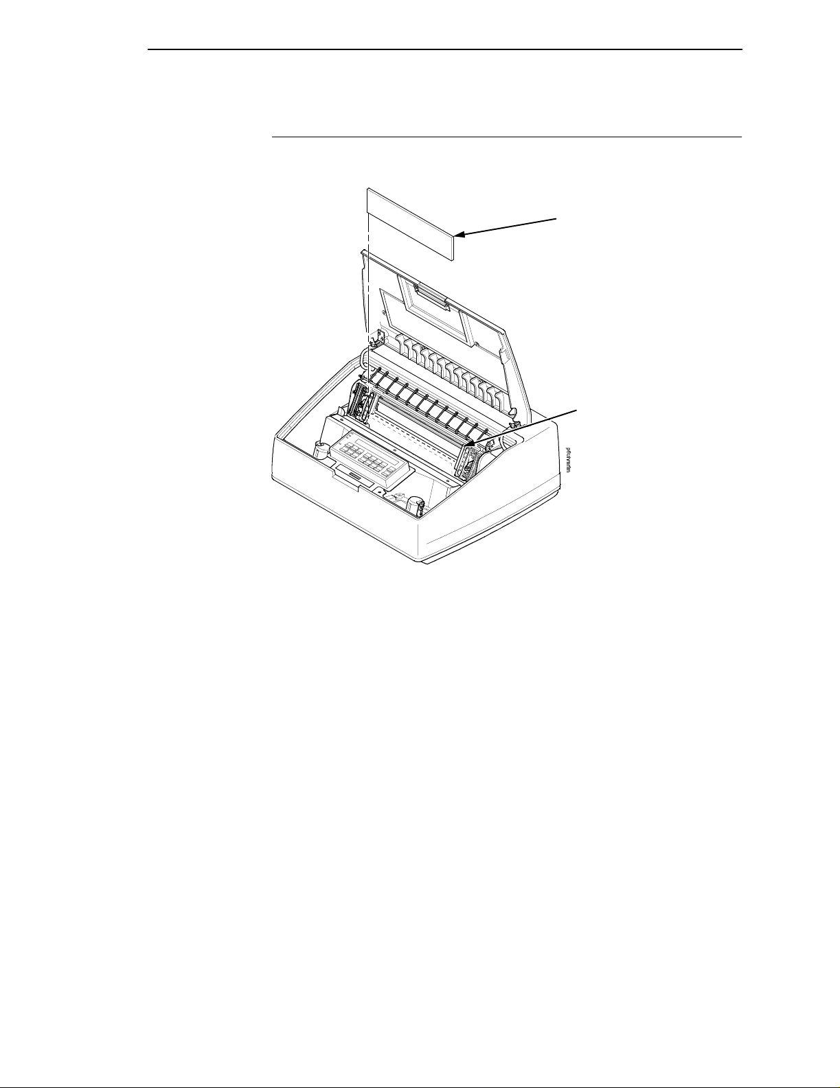
Figure 22. Inside View of the Pedestal Model Showing Paper Exit Options
5. Tighten t he two hinge adjustment thumbscrews.
6. Slide the paper guide slightly to the left and raise it to its upper position for
the top exit.
Paper
Top Paper Exit
Figure 23. Top Back View of the Pedestal Model with Paper Exiting through the Top Paper
Exit
7. Load the paper (see page 66), feeding it out the top paper exit.
50
Page 51

Setting Rear Paper Exit
Setting Rear Paper Exit
1. Press Stop to place the printer in NOT READY state.
NOTE: If there is paper in the printer, unload the paper, then continue with
step 2 of this procedure.
Thumbscrew
Figure 24. Loosening the Hinge Thumbscres, Open View of the Back Rear Pedestal Model
Cover
2. Open the printer cover.
3. Loosen the two hinge adjustment thumbscrews.
4. Slide the cover forward until it stops.
Figure 25. Internal View of the Pedestal Model Showing Paper Exit Options
5. Tighten t he two hinge adjustment thumbscrews.
6. Place the paper guide in its lower position.
51
Page 52

Chapter 2 Connect The Interface And Power Cables (Cabinet Models)
Figure 26. Top Back View of the Pedestal Model with Paper Exiting through the Rear
7. Load the paper (see page 66), feeding the paper out of the rear paper
exit.
Connect The Interface And Power Cables (Cabinet Models )
DANGER
<1> Before powering on the printer, ensure the printer is plugged into
an appropriate power source. Refer to page 27 for information on
the proper source.
<4> Do not connect or disconnect any communication port, teleport,
attachment connector, or power cord during an electrical storm.
<5> Power off the printer and disconnect the power cord before
connecting or disconnecting communication port, teleport, or
attachment cable connector.
1. Verify that the voltage source at the printer site conforms to the
requirements specified on page 28. Make sure that the printer power
switch is set to OFF. See Figure 29 on page 54.
2. Open the front cabinet door, remove and open the cardboard box
containing the power cord, printer ribbon, and operator panel overlay
label. Refer to “Printer Specifications” on page 289 for recommended
cables. Documentation is stored in a pouch container on the left interior
side of the cabinet.
52
Page 53
I/O Connector
Connect The Interface And Power Cables (Cabinet Models)
Setting Rear Paper Exit
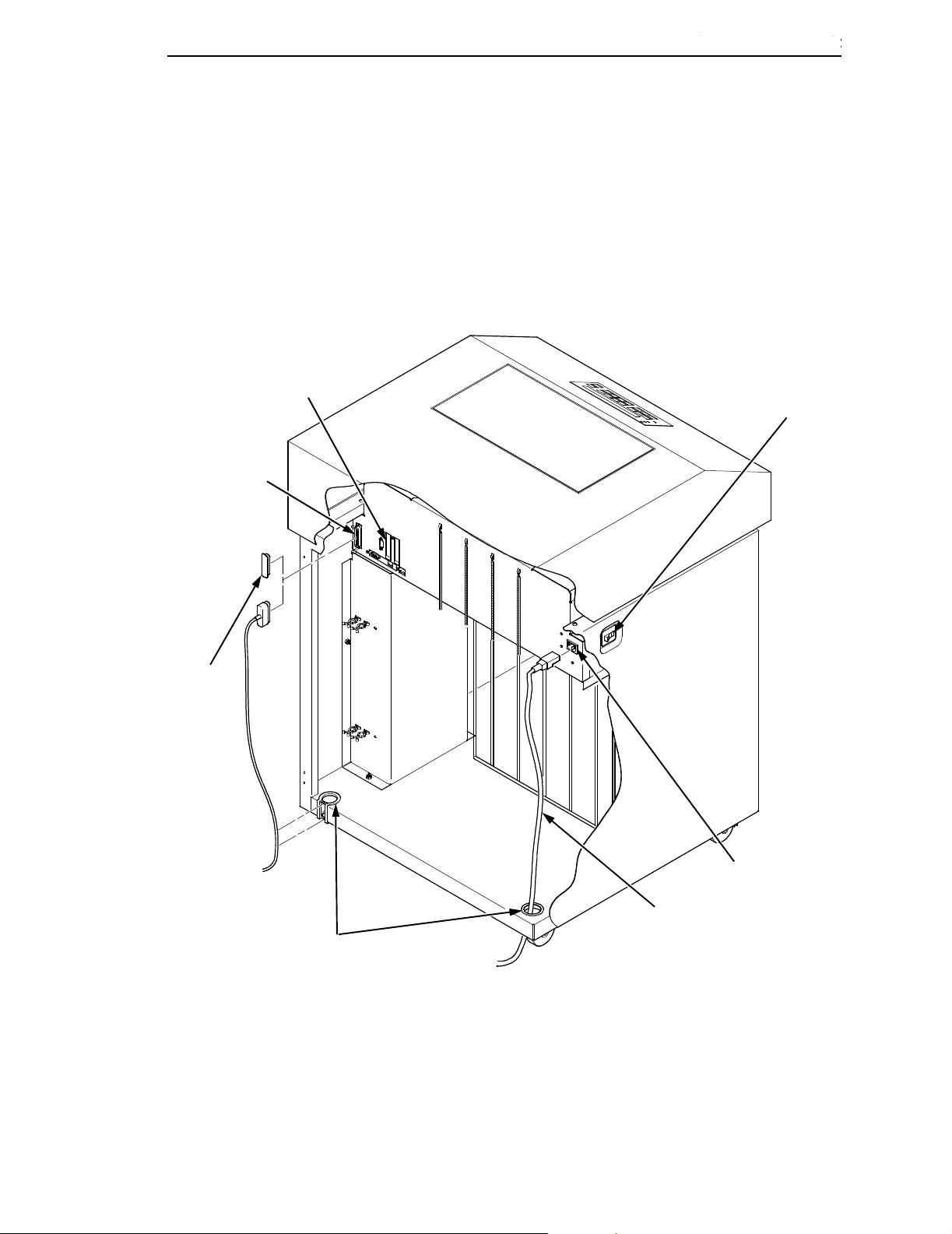
3. Connect the customer supplied interface cable from the host computer to
the appropriate printer interface connector (refer to Figure 27 through
Figure 32).
4. Thread the power cable connector up through the notch in the lower-right
back corner of the cabinet (see Figure 31). Plug the power cord into the
printer AC power connector, then into the AC power outlet.
Host Interface
Connectors
Power
Switch
I/O Cover
AC Power
AC Power
Cable
Cable-Routing
Notches
Connector
NOTE:
(1)
The Dataproducts adapter feature attaches to the PC
Parallel interface connecto r.
(2)
Twinax, Coax, and Ethernet Interfaces appear only if these
features are installed.
Figure 27. Internal Back View of the Cabinet Model Showing Interface and Power Cable
Connections
53
Page 54

Chapter 2 Connect The Interface And Power Cables (Cabinet Models)
Figure 28. Interior Back View of the Cabinet Model Showing Product Description Label
Location
1. Check the product description label to verify that the voltage source at the
printer site conforms to the requirements specified on page 28.
Figure 29. Power Switch Turned OFF
54
2. Make sure the printer switch is set to OFF.
Page 55

Connect The Interface And Power Cables (Cabinet Models)
I/O Connector
Setting Rear Paper Exit
I/O Cover
Figure 30. Upper-Rear Inside View of the Cabinet Model Showing I/O Cover Removal
3. Open the cabinet rear door.
4. Remove the cover from the I/O connector you have selected.
I/O Cable
Grommet
6ciocabl
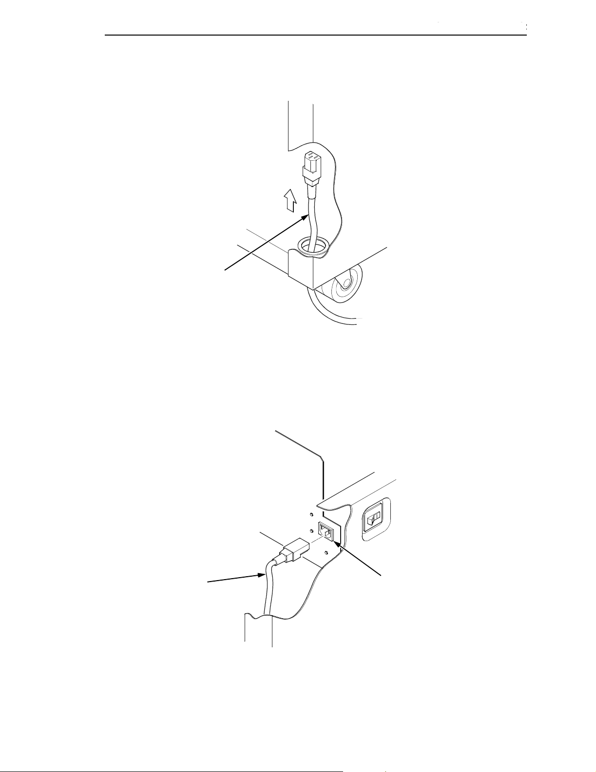
Figure 31. Bottom-Rear Inside View of the Cabinet Model Showing the Cable Routing Notch
5. Locate the notch in the lower-left corner of the back of the cabinet.
6. Hold the I/O cable below its connector, and gently push the cable through
the opening in the grommet seated in the notch.
55
Page 56

Chapter 2 Connect The Interface And Power Cables (Cabinet Models)
I/O Connector
I/O Plate
Cable
Connector
Figure 32. Upper Inside View of the Cabinet Model Showing Cable Connector Attachment
7. Pull the cable up through the notch until it reaches the I/O plate.
8. Attach the cable connector to the printer I/O connector.
9. Secure the cable to the printer using the two cable standoffs.
Strap
56
Figure 33. Open Cabinet Front Door Showing the Printer Accessories Package
10. Open the cabinet front door and cut the strap that secures the box, which
contains the power cord, printer ribbon, control panel overlay labels, and
documentation.
11. Open the box and remove the power cord, overlays, and documentation.
Page 57
Power Cord
Connect The Interface And Power Cables (Cabinet Models)
6
c
p
r
c
r
d
Setting Rear Paper Exit
Figure 34. Rear Inside View of the Cabinet Model Showing the Power Cord Route
12. Guide the power cord up through the hole in the lower right back corner of
the cabinet.
13. Thread the power cord inside the bracket where the gas spring is
attached.
Power
Cord
AC Power
Connector
6cprcrd2
Figure 35. Rear Inside View Cabinet Model Showing Power Cord Attachment
14. Plug the power cord into the printer AC power connector, then into the AC
power outlet.
57
Page 58

Chapter 2 Connect The Interface And Power Cables (Pedestal Models)
Connect The Interface And Power Cables (Pedest al Models )
DANGER
<1> Before powering on the printer, ensure the printer is plugged into
an appropriate power source. Refer to page 27 for information on
the proper source.
<4> Do not connect or disconnect any communication port, teleport,
attachment connector, or power cord during an electrical storm.
<5> Power off the printer and disconnect the power cord before
connecting or disconnecting communication port, teleport, or
attachment cable connector.
1. Verify that the voltage source at the printer site conforms to the
requirements specified on page 28.
2. Open the box containing the power cord, printer ribbon, and operator
panel overlay label. Refer to “Cables” on page 297 for recommended
cables.
58
Page 59

Connect The Interface And Power Cables (Pedestal Models)
Setting Rear Paper Exit
Parallel Connector
Auxiliary I/O
Serial Connector
NOTE:
(1)
The Dataproducts adapter feature attaches to the PC
Parallel interface connector.
(2)
Twinax, Coax, and Ethern et I nterfaces appear only if these
features are installed.
A
p6cprs wt
AC Power Connector
A
Power Switch
On Off
Figure 36. Views of Interface and the AC Power Connector
3. Make sure that the printer power switch is set to OFF. See Figure 29 on
I/O Connector
4. Remove the cover from the I/O connector you have selected.
page 54.
Figure 37. I/O Cover Removal from the Interface
59
Page 60

Chapter 2 Connect The Interface And Power Cables (Pedestal Models)
I/O Connector
Cable
Connector
Figure 38. View of the Printer Interface Showing Cable Connector Attachment
5. Attach the cable connector to the printer I/O connector.
PC Power Outlet
Power
Cord
Figure 39. View of the Power Cord Attachment
60
6. Plug the power cord into the printer AC power connector, then into the AC
power outlet.
Page 61

Connect The Interface And Power Cables (Pedestal Models)
Dataproduct s I/O Adap ter
Dataproducts
Standard Adapter
Setting Rear Paper Exit
Centronics, Ethernet
Auxiliary I/O
Diagnostic
Serial RS-232/RS-422
Pedestal Models
Ethernet
Auxiliary I/O
Centronics
Serial RS-23
Diagnostic
Cabinet Models
Figure 40. Pedestal and Cabinet Model Dataproducts I/O Adapter
NOTE: Centronics is not present on Network-based models.
61
Page 62

Chapter 2 Attach The Operator Panel Overlay Label
Coax/Twinax
Network
10/100Base-T
Figure 41. Optional Interface Types for Auxiliary I/O
Attach The Operator Panel Overlay La bel
Power
Ready
Processing
Attention
Menu
Printer
Configuration
Scroll
Scroll
Enter
Return
Micro
Micro
Line
Feed
View
Form
Feed
Set Top
of Form
Dataproducts
Long Line
Start
Stop
Cancel
Eject/
Restore
62
Figure 42. The Operator Panel Overlay Label
1. Choose the overlay labels in the appropriate language.
2. Attach the operator panel overlay label by adhering it to your operator
panel.
Page 63

Install Th e Ribbon
Refer to the ribbon path diagram molded onto the shuttle cover for the
following steps.
Install The Ribbon
Setting Rear Paper Exit
Cabinet Model Pedestal Model
Figure 43. Cabinet and Pedestal Models with the Printer Cover Open
1. Open the printer cover.
2. Pedestal models: pull the operator panel up and out of the way. The
operator panel can be pulled toward you to provide clearance.
63
Page 64

Chapter 2 Install The Ribbon
Tractor Door
Figure 44. View of the Forms Thickness Lever in the Raised Position
3. Raise the forms thickness lever as far as it will go.
Forms Thickness
Lever
4. Press STOP to silence the alarm.
5. Close the tractor doors.
6. Remove the ribbon spools from the package.
Spool
Right Hub
Latch
Figure 45. View of the Right Ribbon Hub with Ribbon Spool Above
7. With the ribbon supply to the outside, squeeze the right hub latch and
place the full spool on the right ribbon hub.
64
8. Press the spool down until the hub latch snaps into place.
NOTE: The ribbon must not be twisted. A twisted ribbon can lower print
quality, shorten ribbon life, and cause paper or ribbon jams.
If you are installing a “Clean Hands” ribbon (identified by a long
metalic leader), the leader will enable you to install the ribbon without
getting ink on your hands.
Page 65

Install The Ribbon
Setting Rear Paper Exit
Left Ribbon Spool
Cabinet Models
Forms Thickness
Lever
Left Ribbon
Spool
Pedestal Models
Forms Thicknes s
Lever
Figure 46. Cabinet and Pedestal Models, Interior View of Ribbon Installation
9. Starting from the right ribbon spool, thread the ribbon around the right
ribbon guide, under the right tractor door, between the hammer bank
cover and ribbon mask, and along the ribbon path to the left ribbon guide.
10. Place the empty spool on the left hub.
11. Press the spool down until the hub latch snaps into place.
12. Turn the left spool by hand and check to ensure that the ribbon tracks
correctly in the ribbon path and around the ribbon guides.
NOTE: Printers with the “Clean Hands” ribbon automatically load the ribbon
when the first print job is sent.
13. Close the forms thickness lever.
65
Page 66

Chapter 2 Load The Paper
Load The Paper
Figure 47. Cabinet and Pedestal Models with Printer Cover Open
1. Open the printer cover.
Tractor Door
Forms Thickn ess Lever
Figure 48. View of the Forms Thickness Lever in the Raised Position
66
2. Raise the forms thickness lever as far as it will go.
3. Open the tractor doors.
Page 67

Setting Rear Paper Exit
Label
Load The Paper
Figure 49. Interior Rear View of the Cabinet Model Paper Supply Label Location
4. Prepare the paper supply:
Cabinet models:
a. Open the front door of the printer cabinet.
b. Place the paper supply inside the printer, on the floor of the cabinet.
c. Align the paper supply with the front label on the floor of the printer.
d. Ensure that the paper pulls freely from the box.
Cabinet Model
Paper Slot
Paper Slot
Pedestal Model
Figure 50. Side View of the Cabinet and Pedestal Models Paper Feed
Pedestal models:
a. Place the paper supply on the floor in front of the printer, or on the
optional paper shelf, if attached.
b. Ensure that the paper pulls freely from the box.
67
Page 68

Chapter 2 Load The Paper
5. Feed the paper up through the paper slot.
NOTE: Be sure the paper feeds between the two wire guides.
Only the 6400-i20, -i2s, and -i24 printer models contain the paper
path guide as shown in Figure 50.
6. Hold the paper in place with one hand (to prevent it from slipping down
through the paper slot) while pulling it through from above with your other
hand.
7. Pull the paper above and behind the ribbon mask, which is a silver metal
strip with a clear plastic edge protector. Refer to the ribbon path diagram
on the shuttle cover.
Left Tractor Door
Paper
Left Tractor Lock
Figure 51. View of Paper Loaded Onto the Left Tractor with Door Closed and Tractor Lock
Lowered
8. Load the paper onto the left tractor sprockets.
9. Close the left tractor door.
68
Page 69

Setting Rear Paper Exit
Load The Paper
ATTENTION
T o avoid damage to the printer caused by printing on the platen, always
align the edge of the left tractor door with the number “1” on the paper
scale.
Tractor Splined Shaft
Tractor
Paper
Paper Scale
Figure 52. View of the Paper Scale Used as a Guide
10. If adjustment is necessary:
a. Unlock the left tractor.
b. Slide the tractor until it is directly to the left of the number “1” on the
paper scale and lock it. You can also use the paper scale to count
columns.
69
Page 70

Chapter 2 Load The Paper
Figure 53. Paper Loaded onto the Right Tractor Sprockets
Right Tractor Door
11. Unlock the right tractor.
12. Load the paper onto the right tractor sprockets.
13. Close the tractor door.
14. Make sure the leading edge of the first sheet of paper is parallel to the
tractor splined shaft. If the paper is misaligned, reload it onto the tractor
sprockets until its edge is parallel to the splined shaft.
15. Slide the right tractor to remove the paper slack or to adjust for various
paper widths.
16. Lock the tractor.
70
Page 71

Setting Rear Paper Exit
Load The Paper
Forms Thickness Lever
Figure 54. The Forms Thickness Lever in the Lowered Position
17. Turn the vertical position knob to feed the paper up into the paper guide
assembly.
18. Lower the forms thickness lever, and set it to match the paper thickness.
(The A-B-C scale corresponds approximately to 1-, 3-, and 6-part paper
thickness.)
NOTE: Do not set the forms thickness lever too tightly; excessive friction can
cause paper jams, ribbon jams (with potential for ribbon damage),
smeared ink, or wavy print.
19. Press STOP to remove the “LOAD PAPER” fault message from the
display.
20. Press FORM FEED several times to make sure the paper feeds properly
beyond the tractors and over the lower paper guide. Feed sufficient paper
to ensure the paper stacks correctly.
21. Close the printer cover.
22. Close the cabinet door.
23. Press START to place the printer in online mode and resume printing.
NOTE: For cabinet models with the power paper stacker installed, go to
“Power Paper Stacker Option” in the next section. For all other
cabinet models, go to “Set The Top-of-Form” on page 77.
71
Page 72

Chapter 2 Power Paper Stacker Opt io n
Power Paper St ack er Option
This section explains how to set up and use the optional power paper stacker.
The power stacker mechanically directs the paper from the printer to the
paper stacker.
Power Paper S tacker Component Locations
Familiarize yourself with the names and locations of the components shown in
the following illustration before operating the power paper stacker.
Elevator
Disable Switch
Elevator Lift
Handle
Paper Length
Indicator
Bearing Bracket
Pinch Rollers
Paper Throat
Rear
Control
Panel
Wire Paper
Tent
Pull Out Paper Tray
72
Figure 55. View of the Power Paper Stacker Component Locations
Page 73

Setting Up The Power Paper Stacker
Setting Up The Power Paper St ack er
A
Elevator Disable Switch
Elevator Lift Handle
Figure 56. Cabinet Model Rear Door Open Showing Rear Operator Panel
1. Turn the printer ON.
2. Using the rear operator panel, press ONLINE to take the printer offline.
3. Grasp the elevator lift handle and press the elevator disable switch while
raising the elevator to the top of its travel.
A
Paper
Advance
Stacker Up
Stacker
Down
Wire Paper Tent
Paper Tray
Figure 57. Rear View of Cabinet Model Showing Power Stacker Components
4. Make sure the wire paper tent is fitted in the pull out paper tray in the base
of the stacker.
73
Page 74

Chapter 2 Power Paper Stacker Opt io n
A
A
Paddle Shaft
Bearing Bracket
Figure 58. Interior Side View of the Cabinet Model Showing the Paper Length Indicator
5. Set the desired paper length (5-12 inch range), as follows:
Grasping the paddle shaft, push or pull toward the front or the rear of the
printer, setting the desired paper length by aligning indicator notch on the
bearing bracket with the paper length indicator.
6. Press Stacker Down.
Paper Length Indicator
Loading And St art ing The Power Pa per S t ack er
1. Using the rear operator panel, press the PAPER ADVANCE key and
hand feed the paper until paper reaches the wire tent and there is an
excess of 3 to 5 pages. Be certain the paper passes through the paper
stacker throat smoothly.
2. Stack the 3-5 sheets of paper on top of the wire paper tent, making sure
the paper lies with the natural folds.
3. On the printer’s main operator panel, the printer displays “OFFLINE.” If a
message other than “OFFLINE” displays in the operator panel, refer to
Chapter 6, “Routine Service and Diagnostics” on page 265.
4. Press the START key on the operator panel or the ONLINE key on the
rear operator panel. “READY” displays on the LCD and the “ONLINE” on
the rear operator panel is lit. The stacker frame returns to its proper
position for printing.
5. Check to ensure paper is still centered between paper guides.
6. Close the rear cabinet door.
74
Page 75

Checking The Paper Feed
Loading And Starting The Power Paper Stacker
Checking The Paper Feed
Figure 59. Side View of the Cabinet Model Showing Paper Feed Route
Cabinet Models:
1. Check that the paper feeds correctly.
2. Press the Form Feed key several times to ensure that the paper feeds
properly beyond the tractors and over the paper guide assembly.
3. Ensure that the paper folds the same way in the stacking area as it does
in the supply area.
4. Close the front and rear cabinet doors, if the length of the form allows.
75
Page 76

Chapter 2 Checking The Paper Feed
p6clod4
Figure 60. Side View of the Pedestal Model Showing Paper Feed Routes
Pedestal Models:
NOTE: When using the top exit paper path, paper cannot be stacked. Paper
is intended to be removed after each print job is completed.
• For rear paper exit: Press the Form Feed key several times to ensure
that the paper feeds properly beyond the tractors, over the paper guide
assembly, and through the paper exit slot in the rear of the cabinet.
Ensure that the paper folds the same way in the stacking area as it does
in the supply area.
• For top paper exit: Press the Form Feed key several times to ensure
that the paper feeds properly beyond the tractors, over the paper guide
assembly, and through the paper exit slot.
76
Page 77

Set The Top-of-Form
Loading And Starting The Power Paper Stacker
Vertical Position Knob
Forms Thickness Lever
Set The Top-of-Form
Figure 61. The Forms Thickness Level in the Raised Position
1. Raise the forms thickness lever as far as it will go. The “CLOSE PLATEN”
message appears on the operator panel.
2. Press any key on the operator panel to silence the alarm.
TOF Indicator
Perforation
Vertical Position Knob
Figure 62. The First Print Line Aligned with the TOF Indicator
3. Locate the TOF indicator. It is the small tab located on the left tractor
door.
4. Turn the vertical position knob up or down to align the top of the first print
line with the TOF indicator. For best print quality, it is recommended that
the top-of-form be set at least 1/2 inch below the perforation.
NOTE: For exact positioning, press the Micro
paper vertically in 1/72 inch increments. The keys work in both online
and offline mode.
or Micro keys to move the
77
Page 78

Chapter 2 Test The Printer
Figure 63. The Forms Thickness Lever in the Lowered Position
5. Lower the forms thickness lever. The CLOSE PLATEN fault clears
6. Set it to match the paper thickness. If you are using single–part forms, set
NOTE: Do not set the forms thickness lever too tightly; excessive friction can
7. Press Set Top of Form. The paper moves downward to the top-of-form
Test The Printer
To run an initial printer test, print the current configuration page. See “Printing
The Current Configuration” on page 85.
On the configuration printout, examine the print quality of the characters. They
should be fully formed and of uniform density. If text characters do not appear
correctly formed or if the test does not run, contact your IBM service
representative.
Forms Thickness Lever
automatically.
the forms thickness lever so that “A” is next to the indicator (refer to the
note on the shuttle cover).
cause paper jams and ribbon jams with potential for ribbon damage,
smeared ink, or wavy print.
print position.
78
The printer is now ready for configuration. Refer to Chapter 3, “Configuring
the Printer” for more information.
Page 79

3 Configuring the Printer
Overview
IMPORTANT
Configuration directly affects printer operation. Do not try to change the
configuration of your printer until you are thoroughly familiar with the
procedures in this chapter.
To print data, the printer must respond correctly to signals and commands
received from the host computer. Configuration is the process of matching the
printer operating characteristics to those of the host computer and to specific
tasks, such as printing labels, or printing on different sizes of paper. The
characteristics that define the printer response to signals and commands
received from the host computer are called configuration parameters.
You can configure the printer by pressing operator panel keys or by sending
control codes from the host computer. This chapter explains how to use the
operator panel to change individual parameters and save them as a custom
configuration.
Your programmer’s reference manuals provide information about control
codes.
The Configurations
A configuration consists of a group of parameters, such as line spacing and
forms length. Your printer contains the following configurations:
• Four preloaded configurations that have been customized for printer
setup.
• The factory default configuration. It can be loaded, but it cannot be
altered. A list of all the parameters and their values begins on page 87.
• Four configurations that you can customize for unique print job
requirements. The process of creating customized configurations is
explained on page 92.
79
Page 80

Chapter 3 The Configuration Main Menu
Active V ers us Saved Configura tions
When you change a parameter value, it is active as long as the printer is on or
until it is changed again. This is true whether you use the operator panel or
send a control code from the host. Parameter values defined by control codes
override the active operator panel parameters when the printer is using any of
the parallel or serial interfaces. For example, if you set the line spacing to 6 lpi
with the operator panel, and application software later changes this to 8 lpi
with a control code, the control code setting overrides the operator panel
setting.
Using the operator panel, you can save the parameters as a customized
configuration that is stored in non-volatile random access memory (NVRAM).
A saved configuration is not lost when you power off the printer.
NOTE: Saved configurations are also referred to as “custom sets.”
There are no control codes that allow you to save a parameter in NVRAM.
However, you can save a configuration defined partially by control codes and
store it in NVRAM using the operator panel. You can also save configuration
values using PTR_SETUP (see page 111.)
The Configuration Main Menu
Figure 64 shows an overview of the printer configuration menus. The pages
that follow describe how to enter program mode, print the current
configuration, change configuration parameters, and save and load custom
sets.
For specific configuration menu options and their descriptions, refer to
Chapter 4, “The Configuration Menus” on page 103.
NOTE: The menus that are displayed from the operator panel are determined
by the installed features.
Each feature is shipped with a document that describes the feature in
detail. For more information about these documents, see the “Related
Documents” section on page 15.
80
Page 81

Active Versus Saved Configurations
The Configuration Main Menu
Printer
Control
page 106
Interface Selection
Display Language
Alarm Control
Print Direction
Hex Print Mode
Power On State
Paper Jam Detection
Forms Speed
Set Platen at Bottom
of Form
Shuttle Timeout
Energy Saver Timer
OCR Font Density
Eject/Restore
PTR Setup Option
File System
Power Stack er
Auto Elevator
Print Line Select
Single Bank Select
(6)
(6)
(11)
Configuration
Management
page 113
Recall Custom Set
Save Current Values
Delete Custom Set
Change Power On Set
Protect Custom Sets
Print Custom Set Values
Name Custom Sets
Reset Custom Set Names
(11)
Twinax
Interface
page 117
Print Language
Print Character Table
Active Print Language
Printer Emulation
Printer Address
World Trade
Cancel Buffers
Early Print Complete
Hex Transparent Control
Undefined Character
Reporting
Undefined Character
Substitution
Load Alternate
Character Option
LAC Approximation
Print Text Direction
Override Host
Format Control
Maximum Printable
Width
Hex Print Mode
C/T Hotport
(1)
(7)
(2)
(8)
Coax
Interface
page 126
Print Language
Print Character Table
Active Print Language
PA1
PA2
Buffer Reprint
Printer Emulation
Early Print Complete
SCS Buffer Control
Cancel Buffers
Hex Transparent Control
Mono/Dual Case
Undefined Character
Substitution
Print Text Direction
Image Buffer Size
Intervention Required
Compatibility Options
Translate Table
Override Host
Format Control
Maximum Printable
Width
C/T Hotport
Hex Print Mode
(1)
(9)
(8)
5250
Interface
Print Language
Print Character Table
Active Print Language
Hex Transparent Control
Undefined Character
Reporting
Undefined Character
Substitution
Print Text Direction
Override Host
Format Control
Maximum Prin t Width
(10)
page 139
NOTE:
(1)
The Twinax and Coax interface menus only appear in the menus if the IBM Coax/
Twinax feature is installed.
(2)
The Early Print Complete option appears in the Twinax menu only if the IPDS feature is
installed.
(3)
IPDS, Code V Emulation, and IGP Emulation options appear in the menus only if these
features are installed. Menus are shown in Appendix D.
(4)
Ethernet information only appears when the ethernet feature is installed.
(5)
Either the Network Setup menu or the Parallel Interface menu will display. They cannot
display at the same time.
(6)
If installed.
(7)
Not if 4234-12 is running IPDS code.
(8)
Only if Autoswitching is enabled.
(9)
Only if Coax Emulation is enabled.
(10)
The 5250 and 3270 Interface menu only appear in the menus if the TN5250/3270
feature is installed.
(11)
6400-i20 and -i24 models only.
Figure 64. Configuration Main Menu
81
Page 82

Chapter 3 The Configuration Main Menu
3270
Interface
(10)
page 145
Print Language
Print Character Table
Active Print Language
Early Print Complete
Hex Transparent Control
Mono/Dual Case
Undefined Character
Substitution
Print Text Direction
Intervention Required
Compatibility Options
Override Host
Format Control
Maximum Printable Width
Emulation
Configuration
page 186
Active Emula t ion
(3)
IPDS
(6)
ANSI
IGP Emulation
Code V Emulation
(3)
(3)
ASCII Printer
Emulation
Printer Emulation
Configuration
Print Format
Network
(6)
Setup
page 155
Adapter Address
Adapter Parameters
Ethernet Address
Ethernet Parameters
Wireless Address
Wireless Parameters
Operator
Print Tests
page 242
Printer Demonstration*
Print Error Log
Ripple Print
All E’s
All H’s
All E’s + FF
Underlines
Adapter Test Page
Ethernet Test Page
Parallel
Interface
page 170
Interface Type
PC Parallel
Dataproducts
IEEE 1284
Parallel Hotport
Information
page 244
Installed Memory
Power On Time
Printing Time
Print Strokes
11 Inch Pages
(4)
(4)
(5)
Printer
Serial
Interface
page 180
Interface Type
Data Protocol
Baud Rate
Data Bits
Stop Bits
Parity
Data Terminal Ready
Request to Send
Buffer Size in
Kilobytes
Poll Character
One Char Enquiry
Serial Hotport
Framing Errors
RibbonMinder
page 245
New Ribbon
Ribbon Action
Ribbon Type
Ribbon End Point
New Ribbon Detect
82
Figure 64. Configuration Main Menu (con’t)
Page 83

Using The Operator Panel
Power
Ready
Processing
READY
Active Versus Saved Configurations
Using The Operator Panel
Attention
Menu
Printer Configuration
Scroll
Scroll
Enter
Return
Micro
Micro
Line
Feed
View
Form
Feed
Set Top
of Form
Start
Stop
Cancel
Eject/
Restore
Figure 65. The Operator Panel
The operator panel is shown above. During the configuration process, you will
use the Scroll↑, Scroll↓, Enter, and Return keys on the operator panel to
access configuration settings and diagnostic tests via the configuration
menus. As you access menus and options, menu names and option values
appear on the operator panel message display (sometimes referred to as
LCD, or Liquid Crystal Display).
This chapter provides numerous examples of how to use the operator panel
keys and indicator message display to configure the printer.
83
Page 84

Chapter 3 Program Mode
Program Mode
The printer is in Program mode whenever the configuration menus and option
values are displayed on the operator panel message display. Program mode
is either locked or unlocked. In order to select new configuration values, you
must unlock Program mode. In order to prevent accidental changing of the
configuration settings, you may lock Program mode.
Unlocking The Program Mo de
To use the operator panel to change the configuration settings, Program
mode must be unlocked. When Program mode is unlocked, pressing the
Enter key selects configuration values as the active values, that is, places
them into printer DRAM. An asterisk (*) after a displayed setting shows it is
entered into memory.
Press the Scroll↑ + Scroll↓ keys at the same time to unlock Program mode.
The following message will appear briefly:
OPERATOR MENU
UNLOCKED
Locking The Program Mode
When Program mode is locked, you cannot use the operator panel to change
the configuration settings. However, you can still select the configuration
menus and view the current configuration settings.
Press the Scroll↑ + Scroll↓ keys at the same time to lock Program mode.
The following message will appear briefly:
OPERATOR MENU
LOCKED
84
Page 85

Entering Program Mode
Entering Program Mode
To place the printer in Program mode, press the Menu key.
Printing The Current Co nfiguration
Step Key LCD Result Notes
1. Make sure the printer is on
2. Press NOT READY The printer must be in NOT
Stop
READY mode to print the
configuration.
3. PRESS START TO PRINT
Printer Configuration
4. NOT READY Indicates that the configuration
Start
5. READY The printer is READY for normal
Start
The second method for printing the current configuration, as well as several
other configurations, is to use the Print Custom Set Values menu option,
shown on the following page.
PRESS STOP TO EXIT
You are prompted to press the
Start key before the
configuration prints.
has printed. Date and store the
printout in a safe place. Y ou may
also want to label the printout
(e.g. “Configuration for 2-up
Labels”).
operation.
85
Page 86

Chapter 3 Printing The Current Configuration
Configuration
Management
Recall
Custom Set
Custom Sets
Name
Save Current
Values
Custom Set
Names
Reset
Delete
Custom Set
Change
Power
On Set
Protect
Custom Sets
* = Factory Default
Print Custom
Set Values
Current Custom Set*
Factory Default
Power On Custom Set
All Custom Sets
Custom Set 1
Custom Set 2
Custom Set 3
Custom Set 4
Custom/Preloaded Set 5
Custom/Preloaded Set 6
Custom/Preloaded Set 7
Custom/Preloaded Set 8
The Print Custom Set Values selection on the Configuration Management
menu allows you to print any or all of the configurations shown above. The
default setting, “Current Custom Set,” will print the same information as
pressing the Printer Configuration key. The Current Custom Set is the Power
On configuration until you begin modifying the printer configuration.
Custom sets 1 through 4 do not exist until you save configuration parameters
to them. You must define and save a custom set before you can print it.
Custom/Preloaded Sets 5 through 8 contain configuration sets that assist with
the installation and configuration of this printer.
The other options will only be useful once you have modified and saved the
printer configuration parameter settings.
The Power On Custom Set is defined by the “Change Power On Set” option.
Custom Sets 1 through 8 are defined by the “Save Current Values” option.
These options are described in detail under the Configuration Management
Menu description starting on page 113.
86
Page 87

Factory Default Configuration Values
The factory default values are permanently stored as a configuration. They
cannot be modified or erased. The parameters which display depend on
which interface and emulation is installed.
Below is a representative factory default configuration. Your factory default
configuration will depend on the features installed in your printer.
POWER ON CURRENT CONFIGURATION - FACTORY CONFIGURATION
IBM Printer Configuration
File Part Number XXXXXXX Date XX-XXX-XXXX
Reference Number XXXXXX
DC V2.04D XX-XXX-XX #XXX X XX
EC V2.01B XX-XXX-XX #XXXXXX
BOOT/CMX V1.05E XX-XXX-XX #XXXXXX
SHUTTLE TYPE 1500
FLASH 8 MB
DRAM 8 MB
SECURITY PAL XXXXXX-XXX
CONFIGURATION CODE FC06FF
Factory Default Configuration Values
Entering Program Mode
PRINTER CONTROL
Interface Selection Parallel
Display Language English
Alarm Control Alarm Enabled
Print Direction Bidirectiona l
Hex Print Mode Disable
Power On State Ready
Paper Jam Detection Enable
Forms Speed Normal Speed
Set Platen at Bottom of Form Disable
Shuttle Timeout 5 Seconds
Energy Saver Timer 15 Minutes
OCR Font Density 120 Dots Per Inch
Eject/Restore Standard
PTR Setup Option
Setup Parse Disable
Setup SFCC 21h
File System
Overwrite Files Enable
View File List
93779.sf 177228 Bytes
Plugin.cdm 122066 Bytes
HQ3UPDT.cdm 53480 Bytes
Pluginfp.cdm 206161 Bytes
IF.fnt 339 Bytes
HQ3.fnt 444 Bytes
UIF.ss 21646 Bytes
Plugin.ttf 26928 Bytes
UTT.ss 16582 By tes
Version 67 Bytes
87
Page 88

Chapter 3 Factory Default Configuration Values
Network.dat 1210 Bytes
PTXLogo.gif 1210 Bytes
Ethload 2191652 Bytes
Printron.ec1 262400 Bytes
Optimize&Reboot
Print File List
CONFIGURATION MANAGEMENT
Recall Custom Set Factory Default
Save Current Values Custom Set 1
Delete Custom Set Custom Set 1
Change Power On Set Factory Default
Protect Custom Sets Disable
Print Custom Set Values All Custom Sets
PARALLEL INTERFACE
Interface Type PC Parallel
PC Parallel
Data Bit 8 Enable
Data Polarity Standard
Strobe Polarity Standard
Response Polarity Standard
Busy on Strobe Enable
Latch Data On Leading Edge
Prime Signal Enable
TOF Action at Prime Signal Form Feed at Reset
Buffer Size in Kilobytes 16
Dataproducts
Data Bit 8 Enable
PI Ignored Enable
Data Polarity Standard
Data Request Polarity Standard
Strobe Polarity Standard
Parallel Hotport
Trickle Time 1/4 Sec
Timeout 10 Sec.
Report Status Disable
88
SERIAL INTERFACE
Interface Type RS 232
Data Protocol XON / XOFF
Baud Rate 9600 Baud
Data Bits 8
Stop Bits 1
Parity None
Data Terminal Ready Ready and Buffer Not Full
Request to Send True
Buffer Size in Kilobytes 16
Poll Character 00 Hex
One Char Enquiry Disable
Page 89

Factory Default Configuration Values
Serial Hotport
Trickle Time 1/4 Sec
Timeout 10 Sec.
Report Status Disable
Framing Errors Enable
EMULATION CONFIGURATION
Active Graphic Emulation IGP
IGP Emulation
Define CR Code CR = CR
Define LF Code LF = LF
Auto LF Disable
Select SFCC 7E
PI Slew Range 16
CR Edit Disable
Select Font 0
Slash 0 Disable
Lines Per Inch 6 Lines Per Inch
Mono/Dual Case Dual Case
Skip Command Prefix Enable
Power on IGP Enable
Ext Execute Copy Disable
UPC Descenders Enable
Compressed CPI Disable
Ignore Character
Ignore Mode Disable
Select Character 0
IGP100 Compatibility None
Expanded Font Block
Optimized Ratio Disable
ASCII Printer Emulation P-Series Emulation
Printer Emulation Configurations
Proprinter III XL Emulation
Print Language 0437 PC Character Set
Alternate Character Set PC Character Set 1
Define CR Code CR = CR
Auto LF Enable
Define LF Code LF = LF
FF Valid at TOF Enable
20 CPI Condensed En able
Epson Emulation
Character Sets Epson Set
Epson Print Language ASCII (USA)
Define CR Code CR = CR
Auto LF Enable
Define LF Code LF = LF
Printer Select Disable
20 CPI Condensed En able
Entering Program Mode
89
Page 90

Chapter 3 Factory Default Configuration Values
P-Series Emulation
Character Sets IBM PC
Print Language
IBM PC ASCII (USA)
Multinational ASCII (USA)
EMCA Latin 1
DEC Multinational ASCII (USA)
Control Code 06 8.0 LPI
Control Code 08 Elongated
Define CR Code CR = CR
Auto LF Disable
Overstrike Enable
Define LF Code LF = CR + LF
Select SFCC 1
Alternate Set 80 - 9F Control Code
P-Series XQ Emulation
Control Code 06 8.0 LPI
Define CR Code CR = CR
Auto LF Disable
Define LF Code LF = CR + LF
Compressed Print Char 01 SOH
Elong/Alt. Font Elng = BS Font = SO
High Speed Print Mode Char 02 STX
EVFU Select Enable
Upper Case Select Disable
Slew Relative 1 to 16 Lines
Serial Matrix Emulation
Character Sets IBM PC
Print Language
IBM PC
Multinational
Control Code 06 8.0 LPI
Define CR Code CR = CR
Auto LF Enable
Overstrike Enable
Define LF Code LF = LF
Printer Select Disable
Alternate 80 - 9F Control Code
90
Page 91

Factory Default Configuration Values
Print Format
Characters Per Inch 10.0 Characters Per Inch
Lines Per Inch 6.0 Lines Per Inch
DBCS CPI 6.7 CPI
Forms Width
Forms Width in inches 13.6 inches
Forms Width in MM 345.4 MM
Forms Width in
Characters 136 Characters
Forms Length
Forms Length in inches 11.0 inches
Forms Length in mm 279.4 mm
Forms Length in lines 66 lines
Print Quality DP Quality
Print Character Table
Print Attributes
Proportional Spacing Disable
Italic Print Disable
Slashed Zero Disable
Text Position Bottom of Line
Margins
Left Margin 0 Characters
Right Margin 0 Characters
Bottom Margin 0 Lines
Perforation Skip Disable
Reset Command Loa d Facto ry
Entering Program Mode
OPERATOR PRINT TESTS Printer Demonstration
PRINTER INFORMATION
Installed Memory 8 MB
Power On Time: XXX.X Hours
Printing Time: XX Hours
Print Strokes XXXXXXX
11 Inch Page XXXX
RIBBONMINDER
New Ribbon 99%
Ribbon Action Display
Ribbon Type Gold Series 90
Ribbon End Point Normal
New Rib. Detect Enable
91
Page 92

Chapter 3 Changing Parameters
Changing Parame ters
Printer
Control
Interface
Selection
* = Factory Default
Display
Language
Alarm
Control
Print
Direction
Bidirectional*
Unidirectional
Hex Print
Mode
The following procedure shows you how to change a configuration setting.
Changing the Print Direction from the factory default setting BIDIRECTIONAL
to the setting UNIDIRECTIONAL is provided as an example. Print Direction is
one of the Printer Control menu options. The procedure is similar for other
configuration changes. Use these basic guidelines to navigate the
configuration menus and change other parameters.
NOTE: Press Start at any time to exit the configuration menu.
Step Key LCD Results Notes
1. Determine which parameters you want to change and what the new values will be. In this
example, the value for the PRINT DIRECTION parameter will be changed from
“BIDIRECTIONAL” to “UNIDIRECTIONAL.”
2. Press NOT READY Places the printer in NOT
Stop
READY mode before entering
the operator menus.
3. OPERATOR MENU
Scroll↑ Scroll↓
+
UNLOCKED
Unlocks the Operator Menu,
which allows you to make
configuration changes.
4. OPERATOR MENU
Menu
PRINTER CONTROL
Displays the first Configuration
Main Menu option, PRINTER
CONTROL.
92
Page 93

Changing Parameters
Entering Program Mode
Step Key LCD Results Notes
5. PRINTER CONTROL
Enter
INTERFACE SELECTION
6. PRINTER CONTROL
Scroll↑
UNTIL
PRINT DIRECTION
7. PRINT DIRECTION
Enter
BIDIRECTIONAL*
8. PRINT DIRECTION
Scroll↑
UNIDIRECTIONAL
9. PRINT DIRECTION
Enter
UNIDIRECTIONAL*
Moves into the PRINTER
CONTROL menu.
Moves to the PRINT
DIRECTION parameter.
Move into the PRINT
DIRECTION menu. The asterisk
(*) shows that this is the active
value.
Moves to the next available
option, the UNIDIRECTIONAL
option.
Selects the displayed value. An
asterisk (*) appears indicating
that this choice is now the active
value.
10. Continue this pattern to make all of the changes, using the information in this chapter.
11. To save changes so that they will remain when the printer is reset or powered back on, see
“” on page 94. If you want to use these values without saving, continue to the next step.
12. NOT READY Returns the printer to the NOT
Stop
13. OPERATOR MENU
Scroll↑ Scroll↓
+
LOCKED
READY mode.
Locks Program mode and the
Operator Menu.
14. READY Places the printer in READY
Stop
mode, prepared for normal
operation.
93
Page 94

Chapter 3 Saving Your Configuration In A Custom Set
Saving Your Configuration In A Custom Set
Configuration
Management
Recall
Custom Set
Custom Sets
* = Factory Default
Print Custom
Set Values
Name
Save Current
Values
1*
2
3
4
5
6
7
8
Custom Set
Reset
Names
Delete
Custom Set
Change
Power On Set
Protect
Custom Sets
Once you have changed all of the necessary parameters, it is recommended
you save them as a configuration that can be stored and loaded later for
future use. You can save your configurations to meet different print job
requirements.
94
The saved configurations (called custom sets) are stored in NVRAM—they
will not be lost if you power off the printer.
Later, you can load one of the configurations for a specific print job. This
eliminates the need to change settings, such as CPI and LPI, for each new
job. See page 97 for details on loading configurations.
You may want to print records of your configurations (see page 85) and store
them in a safe place, such as inside the printer cabinet.
If you do not save your configuration before you power off the printer, all of the
new parameter values that have not been saved to NVRAM will be erased.
When you power the printer on again, the power-on configuration will load. If
no configuration has been designated as the power-on configuration, the
factory configuration will load.
NOTE: To avoid overwriting an existing custom set, the Protect Custom Sets
parameter must be set to ENABLE. See page 115 for details.
Page 95

Saving Your Configuration In A Custom Set
Entering Program Mode
Step Key LCD Results Notes
1. Press NOT READY Places the printer in NOT
Stop
READY mode.
2. OPERATOR MENU
Scroll↑ Scroll↓
+
UNLOCKED
3. OPERATOR MENU
Menu
PRINTER CONTROL
4. OPERATOR MENU
Scroll↑
UNTIL
CONFIGURATION
MANAGEMENT
5. CONFIGURATION
Enter
MANAGEMENT
RECALL CUSTOM SET
6. CONFIGURATION
Scroll↑
UNTIL
MANAGEMENT
SAVE CURRENT
VALUES
Unlocks the Operator Menu,
which allows you to make
configuration changes.
Displays the first Configuration
Main Menu option, PRINTER
CONTROL.
Moves to the Configuration
Management menu option.
Selects the CONFIGURATION
MANAGEMENT menu. The
RECALL CUSTOM SET option
appears.
Moves to the SAVE CURRENT
VA LUE S option.
7. SAVE CURRENT
Enter
VALUES
1*
8. SAVE CURRENT
Scroll↑
UNTIL
VALUES
2
9. SAVING
Enter
CONFIGURATION
Selects the SAVE CURRENT
VALUES menu.
Scrolls through the li st o f cu st om
sets 1 - 8.
Selects the SAVE CURRENT
VALUES option. The message
“SAVING CONFIGURATION”
appears briefly.
95
Page 96

Chapter 3 Saving Your Configuration In A Custom Set
Step Key LCD Results Notes
10. NOT READY Returns the printer to the NOT
Stop
READY mode.
11. OPERATOR MENU
Scroll↑ Scroll↓
+
LOCKED
Locks Program mode and the
Operator Menu.
12. READY Places the printer in READY
Stop
mode, prepared for normal
operation.
13. It is recommended you print your current configuration, as described on page 85.
96
Page 97

Loading Custom Sets Or Factory Default Values
Entering Program Mode
Loading Custom Set s Or Factory Default Values
Configuration
Management
Recall
Custom Set
Factory Default*
Custom Set 1
Custom Set 2
Custom Set 3
Custom Set 4
Custom/Preloaded Set 5
Custom/Preloaded Set 6
Custom/Preloaded Set 7
Custom/Preloaded Set 8
Name
Custom Sets
Save Current
Custom Set
You can load any of the custom set configurations or the factory default
configuration. Factory default parameters are shown starting on page 87. The
loaded configuration remains active as long as the printer is on. The following
procedure shows how to load factory defaults to the printer.
Values
Reset
Names
Delete
Custom Set
Change
Power On Set
* = Factory Default
Protect
Custom Sets
Print Custom
Set Values
If you power off the printer, the power-on configuration will load the next time
the printer is powered on. Selecting the power-on configuration is explained
on page 99.
97
Page 98

Chapter 3 Loading Custom Sets Or Factory Default Values
Step Key LCD Results Notes
1. Press NOT READY Places the printer in NOT
Stop
READY mode.
2. OPERATOR MENU
Scroll↑ Scroll↓
+
UNLOCKED
3. OPERATOR MENU
Menu
PRINTER CONTROL
4. OPERATOR MENU
Scroll↑
UNTIL
CONFIGURATION
MANAGEMENT
5. CONFIGURATION
Enter
MANAGEMENT
RECALL CUSTOM SET
6. RECALL CUSTOM SET
Enter
FACTORY DEFAULT
Unlocks the Operator Menu,
which allows you to make
configuration changes.
Displays the first Configuration
Main Menu option, PRINTER
CONTROL.
Moves to the Configuration
Management menu option.
Selects the CONFIGURATION
MANAGEMENT menu. The
RECALL CUSTOM SET option
appears.
Moves forward to the FACTORY
DEFAULT parameter for the
RECALL CUSTOM SET option.
7. LOADING SAVED
Enter
CONFIGURATION
Loads the set of Factory Default
values. The message “LOADING
SAVED CONFIGURATION”
appears briefly.
8. NOT READY Returns the printer to the NOT
Stop
9. OPERATOR MENU
Scroll↑ Scroll↓
+
LOCKED
READY mode.
Locks Program mode and the
Operator Menu.
98
Page 99

Changing The Power On Configuration
Entering Program Mode
Step Key LCD Results Notes
10. READY Places the printer in READY
Stop
mode, prepared for normal
operation.
Changing The Power On Configuration
Configuration
Management
Recall
Custom Set
Name
Custom Sets
* = Factory Defaul t
Save Current
Values
Reset
Custom Set
Names
Delete
Custom Set
Change
Power On Set
Factory Default*
Custom Set 1
Custom Set 2
Custom Set 3
Custom Set 4
Custom/Preloaded Set 5
Custom/Preloaded Set 6
Custom/Preloaded Set 7
Custom/Preloaded Set 8
Custom Sets
Protect
Print Custom
Set Values
When you power on the printer for the first time, it loads the factory default
configuration. If you power the printer off and then back on, the printer will
load the designated power-on configuration (which is set to Factory Default by
default). It will not load the last saved configuration.
The Change Power On Set option allows you to select a custom set of
configuration values as the power-on configuration. The example on the
following page shows how to select Custom Set 1 as the power-on
configuration.
NOTE: Be sure you define and save a custom set before attempting to use it
as the Power On Custom Set. Otherwise, the current Power On
Custom Set remains selected and the following operator panel
message is displayed:
042 CUSTOM SET DOES NOT EXIST
SAVE FIRST
For example, if you attempt to change the Power On Custom Set
from Custom Set 1 to Custom Set 4, and if Custom Set 4 does not
exist, Custom Set 1 remains the Power On Custom Set.
99
Page 100

Chapter 3 Changing The Power On Configuration
Step Key LCD Results Notes
1. Press NOT READY Places the printer in NOT
Stop
READY mode.
2. OPERATOR MENU
Scroll↑ Scroll↓
+
UNLOCKED
3. OPERATOR MENU
Menu
PRINTER CONTROL
4. OPERATOR MENU
Scroll↑
UNTIL
CONFIGURATION
MANAGEMENT
5. CONFIGURATION
Enter
MANAGEMENT
RECALL CUSTOM SET
6. CONFIGURATION
Scroll↑ Scroll↓
OR
MANAGEMENT
CHANGE POWER ON
SET
Unlocks the Operator Menu,
which allows you to make
configuration changes.
Displays the first Configuration
Main Menu option, PRINTER
CONTROL.
Moves to the Configuration
Management menu option.
Selects the CONFIGURATION
MANAGEMENT menu. The
RECALL CUSTOM SET option
appears.
Moves to the CHANGE POWER
SET ON parameter.
7. CHANGE POWER ON
Enter
SET
FACTORY DEFAULT
8. CHANGE POWER ON
Scroll↑
SET
CUSTOM SET 1
9. CHANGE POWER ON
Enter
SET
CUSTOM SET 1*
100
Displays the first POWER ON
SET option, FACTORY
DEFAULT.
Displays CUSTOM SET 1 as the
POWER ON SET option value.
An asterisk (*) appears after the
change is complete.
 Loading...