

Page 1
6400 Line Matrix Printers
Cabinet and Pedestal Models
Form Number S246–0117–06
©Copyright IBM Corp., 1995, 1998
Page 2

Page 3

S246–0117–06
Page 4

Note!
Before using the information and the product it works with, make sure you read the general
information under “Notices,” located right after the Table of Contents.
Seventh Edition (October 1998)
This edition applies to the 6400 Line Matrix Printer.
The following paragraph does not apply to any other country where such provisions are
inconsistent with local law:
INTERNA
IS” WITHOUT W
NOT LIMITED TO, THE IMPLIED WARRANTIES OF MERCHANTABILITY OR FITNESS FOR A
PARTICULAR PURPOSE. Some states do not allow disclaimer of express or implied warranties
in certain transactions; therefore, this statement may not apply to you.
Requests for IBM publications should be made to your IBM representative or to the IBM branch
office serving your locality. Publications are not stocked at the address given below.
IBM welcomes your comments about this publication. You may send your comments by facsimile
to 1–800–524–1519, by E-mail to
IBM Printing Systems Company
Information Development
Department H7FE, Building 003G
P.O. Box 1900
Boulder, CO 80301–9191, U.S.A.
When you send information to IBM or IBM Printing Systems Company, you grant a nonexclusive
right to use or distribute the information in any way IBM or IBM Printing Systems Company
believes appropriate without incurring any obligation to you.
E Copyright International Business Machines Corporation 1995, 1998.
All rights reserved.
TIONAL BUSINESS MACHINES CORPORA
ARRANTY OF ANY KIND, EITHER EXPRESS OR IMPLIED, INCLUDING, BUT
print_pubs@vnet.ibm.com
TION PROVIDES THIS PUBLICA
, or by mail to:
TION “AS
Note to U.S. Government Users—Documentation related to restricted rights—Use, duplication or
disclosure is subject to restrictions set forth in GSA ADP Schedule Contract with IBM Corp.
Page 5

Table of Contents
1
2
Maintenance Overview
About the Printer 13.
The IBM 6400 Series Printer Family 13.
Printer Evolution 15.
How to Identify the Printer 15.
Important Maintenance Notes 16.
About This Manual 16.
How to Use This Manual 16.
Notes and Notices 16.
Printing Conventions in This Manual 18.
Related Documents 18.
Controls and Indicators 20.
Electrical Controls and Indicators 20.
Mechanical Controls and Indicators 24.
Tools, Test Equipment, and Supplies 26.
. . . . . . . . . . . . . . . . . . . . . . . . . . . . . . . . . . . . . . . . . . . . . . . . . . .
. . . . . . . . . . . . . . . . . . . . . . . . . . . . . . . . . . . . . . . . . . . . . . .
. . . . . . . . . . . . . . . . . . . . . . . . . . . . . . . . . . . . . . .
. . . . . . . . . . . . . . . . . . . . . . . . . . . . . . . . . . . .
. . . . . . . . . . . . . . . . . . . . . . . . . . . . . . . . . . . . . . . . . . . . . . . . .
. . . . . . . . . . . . . . . . . . . . . . . . . . . . . . . . . . . . . . . .
. . . . . . . . . . . . . . . . . . . . . . . . . . . . . . . . . . . . . . . . . . . . . .
. . . . . . . . . . . . . . . . . . . . . . . . . . . . . . . . . . . . . . . . . . . . .
. . . . . . . . . . . . . . . . . . . . . . . . . . . . . . . . . . . . . . . . . . . . .
Installation
. . . . . . . . . . . . . . . . . . . . . . . . . . . . . .
. . . . . . . . . . . . . . . . . . . . . . . . . . . . . .
. . . . . . . . . . . . . . . . . . . . . . . . . . . . . . . . .
. . . . . . . . . . . . . . . . . . . . . . . . . . . . . . .
. . . . . . . . . . . . . . . . . . . . . . . . . . . . . . . . . .
3
Installation 27
. . . . . . . . . . . . . . . . . . . . . . . . . . . . . . . . . . . . . . . . . . . . . . . . . . . . . . . . .
Preventive Maintenance
Cleaning the Printer 29.
Cleaning the Exterior 30.
Cleaning the Interior 30.
Cleaning the Shuttle Frame Assembly 31.
Cleaning the Card Cage Fan Assembly 33.
. . . . . . . . . . . . . . . . . . . . . . . . . . . . . . . . . . . . . . . . . . . . . . . .
. . . . . . . . . . . . . . . . . . . . . . . . . . . . . . . . . . . . . . . . . . .
. . . . . . . . . . . . . . . . . . . . . . . . . . . . . . . . . . . . . . . . . . . .
. . . . . . . . . . . . . . . . . . . . . . . . . . . . .
. . . . . . . . . . . . . . . . . . . . . . . . . . .
Page 6

4
Principles of Operation
5
Line Matrix Printing 35.
Printing Mechanism 38.
Shuttle Frame Assembly 38.
Paper Transport System 41.
Ribbon Transport System 42.
Logical Control of the Printer 43.
Operator Panel 44.
CMX Controller Board 45.
Data Controller 47.
Engine Controller 50.
Power Supply Board 51.
Printer Interface 52.
Graphics 53
. . . . . . . . . . . . . . . . . . . . . . . . . . . . . . . . . . . . . . . . . . . . . . . . . . . . . . . . . . .
. . . . . . . . . . . . . . . . . . . . . . . . . . . . . . . . . . . . . . . . . . . . . . . . .
. . . . . . . . . . . . . . . . . . . . . . . . . . . . . . . . . . . . . . . . . . . . . . . .
. . . . . . . . . . . . . . . . . . . . . . . . . . . . . . . . . . . . . . . .
. . . . . . . . . . . . . . . . . . . . . . . . . . . . . . . . . . . . . . . . .
. . . . . . . . . . . . . . . . . . . . . . . . . . . . . . . . . . . . . . . .
. . . . . . . . . . . . . . . . . . . . . . . . . . . . . . . . . . . . . . . .
. . . . . . . . . . . . . . . . . . . . . . . . . . . . . . . . . . . . . . . . . . . . . . . . . . . .
. . . . . . . . . . . . . . . . . . . . . . . . . . . . . . . . . . . . . . . . . . . . . .
. . . . . . . . . . . . . . . . . . . . . . . . . . . . . . . . . . . . . . . . . . . . . . . . .
. . . . . . . . . . . . . . . . . . . . . . . . . . . . . . . . . . . . . . . . . . . . . . .
. . . . . . . . . . . . . . . . . . . . . . . . . . . . . . . . . . . . . . . . . . . . . . . .
. . . . . . . . . . . . . . . . . . . . . . . . . . . . . . . . . . . . . . . . . . . . . . . . . . . .
Troubleshooting
Introduction 55
Troubleshooting
. . . . . . . . . . . . . . . . . . . . . . . . . . . . . . . . . . . . . . . . . . . . . . . . . . . . . . . .
Aids
. . . . . . . . . . . . . . . . . . . . . . . . . . . . . . . . . . . . . . . . . . . . . . .
55.
Start of Call 56.
Troubleshooting Display Messages 57.
Message List 58.
Troubleshooting Other Symptoms 66.
General Symptom List 67.
Troubleshooting Procedures 70.
Operator Print Tests 135.
Selecting and Running Operator Print Tests 137.
Customer Engineer (CE) Tests 138.
Selecting and Running Customer Engineer Tests 140.
Boot Diagnostics Menu 142.
Hex Code Printout 145.
Printer Information Menu 148.
Displaying Printer Information 149.
Soft vs. Hard Reset 150.
The Power On Sequence 151.
. . . . . . . . . . . . . . . . . . . . . . . . . . . . . . . . . . . . . . . . . . . . . . . . . . . . . . .
. . . . . . . . . . . . . . . . . . . . . . . . . . . . . . . . . . .
. . . . . . . . . . . . . . . . . . . . . . . . . . . . . . . . . . . . . . . . . . . . . . . . . . . . . .
. . . . . . . . . . . . . . . . . . . . . . . . . . . . . . . . . . . .
. . . . . . . . . . . . . . . . . . . . . . . . . . . . . . . . . . . . . . . . . . . . . .
. . . . . . . . . . . . . . . . . . . . . . . . . . . . . . . . . . . . . . . . .
. . . . . . . . . . . . . . . . . . . . . . . . . . . . . . . . . . . . . . . . . . . . . . . .
. . . . . . . . . . . . . . . . . . . . . . . . . . . . . . . . . . . . . . .
. . . . . . . . . . . . . . . . . . . . . . . . . . . . . . . . . . . . . . . . . .
. . . . . . . . . . . . . . . . . . . . . . . . . . . . . . . . . . . . . . . . . . . . . . . . .
. . . . . . . . . . . . . . . . . . . . . . . . . . . . . . . . . . . . . . . . . . . .
. . . . . . . . . . . . . . . . . . . . . . . . . . . . . . . . . . . .
. . . . . . . . . . . . . . . . . . . . . . . . . . . . . . . . . . . . . . . . . . . . . . . .
. . . . . . . . . . . . . . . . . . . . . . . . . . . . . . . . . . . . . . . . . . .
. . . . . . . . . . . . . . . . . . . . . . . .
. . . . . . . . . . . . . . . . . . .
Page 7

6
Adjustment Procedures
Introduction 157.
Preparing the Printer for Maintenance 158.
Returning the Printer to Normal Operation 159.
Belt, Paper Feed Timing, Adjustment 160.
Belt, Platen Open, Adjustment 162.
Paper Drive Motor Pulley Alignment 164.
Paper Scale Alignment 166.
Platen Gap Adjustment 168.
Platen Open Motor Pulley Alignment 170.
Ribbon Guide Alignment 172.
Splined Shaft Skew Adjustment 174.
Adjusting the End of Forms Distance 175.
Hammer Phasing 179.
Loading Flash Memory 181.
Coil Temperature Adjustment 188.
Set Shuttle Speed 189.
. . . . . . . . . . . . . . . . . . . . . . . . . . . . . . . . . . . . . . . . . . . . . . . . . . . . . . .
. . . . . . . . . . . . . . . . . . . . . . . . . . . . . . . .
. . . . . . . . . . . . . . . . . . . . . . . . . . . . . . . . .
. . . . . . . . . . . . . . . . . . . . . . . . . . . . . . . . . . . . . . .
. . . . . . . . . . . . . . . . . . . . . . . . . . . . . . . . . .
. . . . . . . . . . . . . . . . . . . . . . . . . . . . . . . . . . . . . . . . . . . . .
. . . . . . . . . . . . . . . . . . . . . . . . . . . . . . . . . . . . . . . . . . . . .
. . . . . . . . . . . . . . . . . . . . . . . . . . . . . . . . . .
. . . . . . . . . . . . . . . . . . . . . . . . . . . . . . . . . . . . . . . . . . . .
. . . . . . . . . . . . . . . . . . . . . . . . . . . . . . . . . . . . . .
. . . . . . . . . . . . . . . . . . . . . . . . . . . . . . . . .
. . . . . . . . . . . . . . . . . . . . . . . . . . . . . . . . . . . . . . . . . . . . . . . . . .
. . . . . . . . . . . . . . . . . . . . . . . . . . . . . . . . . . . . . . . . . . . . .
. . . . . . . . . . . . . . . . . . . . . . . . . . . . . . . . . . . . . . . .
. . . . . . . . . . . . . . . . . . . . . . . . . . . . . . . . . . . . . . . . . . . . . . . . . .
. . . . . . . . . . . . . . . . . . . . . . . . . . . . .
7
Replacement Procedures and Illustrated Parts List
Organization of This Chapter 191.
Section I: Replacement Procedures
Preparing the Printer for Maintenance 194.
Belt, Paper Feed Timing 195.
Belt, Platen Open 197.
Cable Connectors and Connector Shells 198.
Circuit Board: Controller 200.
Circuit Board: Power Supply 203.
Circuit Breaker 204.
Coax/Twinax Multi-Platform Interface 205.
Cover Assembly, Hammer Bank / Ribbon Mask 206.
Cover Assembly, Shuttle 209.
Cover Assembly, Top, Pedestal Model 210.
Doors, Cabinet, Reversal 211.
Ethernet Interface Assemblies 212.
. . . . . . . . . . . . . . . . . . . . . . . . . . . . . . . . . . . . . . . . . . . . . . . . . .
. . . . . . . . . . . . . . . . . . . . . . . . . . . . . . . . . . . . . . . . . . . . . . . . . . . . .
. . . . . . . . . . . . . . . . . . . . . . . . . . . . . . . . . . . . . . . .
. . . . . . . . . . . . . . . . . . . . . . . . . . . . . . . .
. . . . . . . . . . . . . . . . . . . . . . . . . . . . . . . . . . . . . . . . . . . .
. . . . . . . . . . . . . . . . . . . . . . . . . . . . . .
. . . . . . . . . . . . . . . . . . . . . . . . . . . . . . . . . . . . . . . . . . . .
. . . . . . . . . . . . . . . . . . . . . . . . . . . . . . . . . . . . . . . . .
. . . . . . . . . . . . . . . . . . . . . . . . . . . . . . . . .
. . . . . . . . . . . . . . . . . . . . . . . .
. . . . . . . . . . . . . . . . . . . . . . . . . . . . . . . . . . . . . . . . . . . .
. . . . . . . . . . . . . . . . . . . . . . . . . . . . . . . .
. . . . . . . . . . . . . . . . . . . . . . . . . . . . . . . . . . . . . . . . . . .
. . . . . . . . . . . . . . . . . . . . . . . . . . . . . . . . . . . . . . .
Page 8

Fan Assembly, Cabinet Exhaust 215.
Fan Assembly, Card Cage 216.
Fan Assembly, Hammer Bank 217.
Hammer Spring Assembly 218.
IBM Coax/Twinax Expansion Board 222.
Magnetic Pick-up (MPU) Assembly 223.
Memory Modules and Security PAL 224.
Motor Assembly, Paper Feed 227.
Motor Assembly, Platen Open 229.
Motor Assembly, Ribbon Drive 231.
Network Print Server 232.
Operator Panel Assembly, Cabinet Model 233.
Operator Panel Assembly, Pedestal Model 234.
Paper Guide Assembly 235.
Paper Ironer 236.
Platen 237
Resistors, Terminating 242.
Ribbon Guide Assembly (L/R) 244.
Ribbon Hub 245.
Security Module 224.
Shaft, Splined 246.
Shaft, Support 248.
Shuttle Frame Assembly 249.
Spring Assembly, Gas 251.
Spring, Extension 252.
Switch Assembly, Cover Open 253.
Switch Assembly, Paper Detector 254.
Switch Assembly, Platen Interlock 256.
Tractor (L/R) 258.
. . . . . . . . . . . . . . . . . . . . . . . . . . . . . . . . . . . . . . . . . . . . . . . . . . . . . . .
. . . . . . . . . . . . . . . . . . . . . . . . . . . . . . . . . . . . . . . . . . . . . . . . . . . . . . . . . . . . .
. . . . . . . . . . . . . . . . . . . . . . . . . . . . . . . . . . . . . . . . . . . . . . . . . . . . . . .
. . . . . . . . . . . . . . . . . . . . . . . . . . . . . . . . . . . . . . . . . . . . . . . . . . . . .
. . . . . . . . . . . . . . . . . . . . . . . . . . . . . . . . . . . . . . . . . . . . . . . . . . . . .
. . . . . . . . . . . . . . . . . . . . . . . . . . . . . . . . . . . . . . . . . . . . . . . . . . . . . .
. . . . . . . . . . . . . . . . . . . . . . . . . . . . . . . . . . . . . . . . . . . . . . .
. . . . . . . . . . . . . . . . . . . . . . . . . . . . . . . . . . . . . . . . . . . . .
. . . . . . . . . . . . . . . . . . . . . . . . . . . . . . . . . . . . . . . . . . . . . .
. . . . . . . . . . . . . . . . . . . . . . . . . . . . . . . . . . . . . . . . . . . . . . . . . . .
. . . . . . . . . . . . . . . . . . . . . . . . . . . . . . . . . . . . . . . . . . . .
. . . . . . . . . . . . . . . . . . . . . . . . . . . . . . . . . . . . . . . . . . . . . .
. . . . . . . . . . . . . . . . . . . . . . . . . . . . . . . . . . . . . . . . . . . . . . . . . .
. . . . . . . . . . . . . . . . . . . . . . . . . . . . . . . . . . . . .
. . . . . . . . . . . . . . . . . . . . . . . . . . . . . . . . . . . . . . . . . .
. . . . . . . . . . . . . . . . . . . . . . . . . . . . . . . . . . . . . . .
. . . . . . . . . . . . . . . . . . . . . . . . . . . . . . . . . . . . . . . . . . .
. . . . . . . . . . . . . . . . . . . . . . . . . . . . . . . . . .
. . . . . . . . . . . . . . . . . . . . . . . . . . . . . . . . . . .
. . . . . . . . . . . . . . . . . . . . . . . . . . . . . . . . . . .
. . . . . . . . . . . . . . . . . . . . . . . . . . . . . . . . . . . . . . . .
. . . . . . . . . . . . . . . . . . . . . . . . . . . . . . . . . . . . . . .
. . . . . . . . . . . . . . . . . . . . . . . . . . . . . . . . . . . . . . .
. . . . . . . . . . . . . . . . . . . . . . . . . . . . .
. . . . . . . . . . . . . . . . . . . . . . . . . . . .
. . . . . . . . . . . . . . . . . . . . . . . . . . . . . . . . . . . . . . .
. . . . . . . . . . . . . . . . . . . . . . . . . . . . . . . . . . . . . . .
. . . . . . . . . . . . . . . . . . . . . . . . . . . . . . . . . . . .
. . . . . . . . . . . . . . . . . . . . . . . . . . . . . . . . . . . .
Section II: Illustrated Parts List
Figure 39. Top Cover, Doors, and Casters, Cabinet Model 261.
Figure 40. Paper Stacker and Chains 263.
Figure 41. Control Panel and Cabinet Details 265.
Figure 42. Pedestal Details 267.
Figure 43. Inside Covers, Cabinet Model 269.
Figure 44. Inside Covers and Card Cage, Pedestal Models 271.
. . . . . . . . . . . . . . . . . . . . . . . . . . . . . . . . . . . . . . . . . .
. . . . . . . . . . . . . . . . . . . . . . . . . . . . . . . . .
. . . . . . . . . . . . . . . . . . . . . . . . . .
. . . . . . . . . . . . . . . . . . . . . . . . . . . . . .
. . . . . . . . . . . . . . .
. . . . . . . . . . . . . .
Page 9

Figure 44a. Card Cage Detail, Pedestal Models 273.
Figure 45. Print Mechanism and Circuit Boards: Early Models 275.
Figure 46. Print Mechanism and Circuit Boards: Later Models 277.
. . . . . . . . . . . . . . . . . . . . . . . .
. . . . . . . . . . . .
. . . . . . . . . . . .
Figure 47. Magnetic Pickup Unit (MPU) and Extension Spring 279.
Figure 48. Tractor Shafts 281.
Figure 49. Platen 283.
Figure 50. Motors, Card Cage Fan, and Paper Detector Switch 285.
Figure 51. Circuit Breaker 287.
Figure 52. IBM Coax/Twinax Expansion Board 289.
Figure 53. PrintNet Ethernet Interface Assemblies 291.
Appendices
A Wire Data
B Printer Specifications 333.
C Metric Conversion Tables 345.
D Torque Table 347.
E Safety Inspection Guide 349.
F Abbreviations and Signal Mnemonics 357.
. . . . . . . . . . .
. . . . . . . . . . . . . . . . . . . . . . . . . . . . . . . . . . . . . . . . . . . .
. . . . . . . . . . . . . . . . . . . . . . . . . . . . . . . . . . . . . . . . . . . . . . . . . . .
. . . . . . . . . .
. . . . . . . . . . . . . . . . . . . . . . . . . . . . . . . . . . . . . . . . . . .
. . . . . . . . . . . . . . . . . . . . . . . . .
. . . . . . . . . . . . . . . . . . . . . .
. . . . . . . . . . . . . . . . . . . . . . . . . . . . . . . . . . . . . . . . . . . . . . .
. . . . . . . . . . . . . . . . . . . . . . . . . . . . . . . . . .
. . . . . . . . . . . . . . . . . . . . . . . . . . . . .
. . . . . . . . . . . . . . . . . . . . . . . . . . . . . . . . . . . . . . . . . . . .
. . . . . . . . . . . . . . . . . . . . . . . . . . . . . . .
. . . . . . . . . . . . . . . .
293.
G Cords and Adapters 365.
H Part Numbers 367.
. . . . . . . . . . . . . . . . . . . . . . . . . . . . . . . . . . . . . . . . . . .
I Noise Suppression Devices 375.
J SureStak Power Stacker 377.
Index 413
. . . . . . . . . . . . . . . . . . . . . . . . . . . . . . . . . . . . . . . . . . . . . . . . . . . . . . . . . . . . . . . . . . . .
. . . . . . . . . . . . . . . . . . . . . . . . . . . . . . . . . . .
. . . . . . . . . . . . . . . . . . . . . . . . . . .
. . . . . . . . . . . . . . . . . . . . . . . . . . . . . . .
Page 10

ENERGY STAR
The
EP
A ENERGY
processing equipment to promote the introduction of energy-efficient personal computers,
monitors, and printers, and to reduce air pollution caused by power generation.
IBM participates in this program by introducing printers that reduce power consumption when
they are not being used. This feature can cut energy use by up to 50 percent.
E
Note: The
service.
NERGY
Notices
References in this publication to IBM products, programs, or services do not imply that IBM
intends to make these available in all countries in which IBM operates. Any reference to an IBM
licensed product, program, or service is not intended to state or imply that only IBM’s product,
program, or service may be used. Any functionally equivalent product, program, or service that
does not infringe any of IBM’s intellectual property rights may be used instead of the IBM product.
Evaluation and verification of operation in conjunction with other products, except those expressly
designated by IBM, is the user’s responsibility.
STAR** Computers program is a partnership effort with manufacturers of data
STAR emblem does not represent EPA endorsement of any product or
Any performance data contained in this document was obtained in a controlled environment
based on the use of specific data. The results that may be obtained in other operating
environments may vary significantly. Users of this document should verify the applicable data in
their specific environment. Therefore, such data does not constitute a performance guarantee or
warranty.
IBM may have patents or pending patent applications covering subject matter in this document.
The furnishing of this document does not give you any license to these patents. You can send
license inquiries, in writing, to the IBM Corporation, IBM Director of Licensing, 208 Harbor Drive,
Stamford, Connecticut, United States, 06904.
Electrical Safety
This printer is inspected and listed by recognized national testing laboratories, such as
Underwriters Laboratories, Inc. (UL) in the U.S.A. and Canadian Standards Association (CSA) in
Canada. Listing of a product by a national testing laboratory indicates that the product is designed
and manufactured in accordance with national requirements intended to minimize safety hazards.
IBM equipment meets a very high standard of safety in design and manufacture. Remember,
Page 11

however, that this product operates under conditions of high electrical potentials and heat
generation, both of which are functionally necessary.
Trademarks and Service Marks
The following terms, denoted by an asterisk (*) in this publication, are trademarks of the IBM
Corporation in the United States or other countries or both.
IBM
PC-DOS
SCS
Token-Ring
The following terms, denoted by a double asterisk (**) in this publication, are trademarks of other
companies:
Acrobat Adobe Systems Incorporated
Adobe Adobe Systems Incorporated
Code V Quality Micro Systems
ECOS ECOS Electronics Corp., Inc., Oak Park, Ill.
E
NERGY
Epson Epson Seiko Corporation
Ethernet Xerox Corporation
Fluke John Fluke Manufacturing Co., Inc.
FX Epson Seiko Corporation
IGP Printronix, Inc.
MS-DOS Microsoft Corporation
PrintNet Printronix, Inc.
Printronix Printronix, Inc.
SureStack Printronix, Inc.
Torx Camcar/Textron Inc.
STAR United States Environmental Protection Agency
Page 12
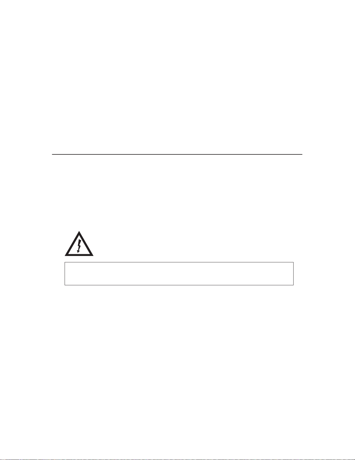
Safety Notices
Danger and Caution notices are numbered to help you find the translated
versions in the
DANGER:
<2> Switch off printer power and unplug the printer power cord before
cleaning the printer.
<3> Hazardous voltages are present in the printer with the power cord
connected to the power source. Switch off printer power and unplug the
printer power cord before proceeding.
<4> Do not connect or disconnect any communication port, teleport,
attachment connector, or power cord during an electrical storm.
<5> Power off the printer and disconnect the power cord before connecting
or disconnecting communication port, teleport, or attachment cable
connector.
IBM 6400 Line Matrix Printer Safety Notices
booklet.
CAUTION:
<2> Over time the upper edge of the paper ironer can become sharp. To
avoid cutting yourself handle the paper ironer on the sides.
<4> To prevent injury from electric shock, wait at least one minute after
powering off before removing the power supply circuit board.
<5> The constant force spring is a high tension spring. To avoid
pinching your fingers, coil the spring slowly and carefully. Do not let
the spring twist or crimp.
Page 13

1
Maintenance Overview
About the Printer
The entire system architecture of an IBM* 6400 line matrix printer is
contained on one circuit board. The use of DRAM and flash memory on this
board permits rapid access to stored printer emulations and fast processing
of print data. A variable-speed shuttle and half-step paper control enables the
printer to print a wide variety of high-volume jobs with minimum maintenance
and maximum reliability.
Although technologically advanced, the printer is easy to use. The operator
can select every printer function at the control panel or by sending printer
control codes in the data stream from the host computer.
This is also an excellent graphics printer, with optional features that simplify
the creation of dot images. The IGP** and Code V** Printronix** emulations
are simple but versatile graphics programming languages that load into flash
memory.
The IBM 6400 Series Printer Family
The IBM 6400 Line Matrix Printer family consists of pedestal mount and floor
cabinet models that print at different speeds, as shown in Table 1. The print
speeds listed in Table 1 are the maximum speeds attainable under certain
conditions. Actual print speed is determined by the interaction of many
variables. For more information, refer to the discussion of Printing Rates in
Appendix B, page 342.
Maintenance Overview
13
Page 14

Models that print 475, 500, 800, 900, and 1000 lpm are available in floor
cabinet and pedestal housings. Models that print 1200, 1400, and 1500 lpm
are available only in floor cabinets.
Table 1. The IBM 6400 Series Printer Family
Model
Number
Print
Speed
Enclosure Hammer
Bank
Data Controller
Clock
6400–004 475 lpm Cabinet 28 Hammers 25 MHz
6400–04P 475 lpm Pedestal 28 Hammers 25 MHz
6400–005 500 lpm Cabinet 28 Hammers 25 MHz
6400–05P 500 lpm Pedestal 28 Hammers 25 MHz
6400–050 500 lpm Cabinet 28 Hammers 40 MHz
6400–P50 500 lpm Pedestal 28 Hammers 40 MHz
6400–008 800 lpm Cabinet 49 Hammers 25 MHz
6400–08P 800 lpm Pedestal 49 Hammers 25 MHz
6400–009 900 lpm Cabinet 49 Hammers 25 MHz
6400–09P 900 lpm Pedestal 49 Hammers 25 MHz
6400–010 1000 lpm Cabinet 60 Hammers 40 MHz
6400–P10 1000 lpm Pedestal 60 Hammers 40 MHz
1
14
6400–012 1200 lpm Cabinet 91 Hammers 25 MHz
6400–014 1400 lpm Cabinet 91 Hammers 40 MHz
6400–015 1500 lpm Cabinet 102 Hammers 40 MHz
1
The microprocessor of the Data Controller unit on the CMX controller board
runs at 25 MHz or 40 MHz, depending on printer model. This means there
are two kinds of CMX controller board for IBM 6400 printers, used as shown
in Table 1. The 40 MHz controller board, however, is backwards compatible
in all models that use the 25 MHz board.
Maintenance Overview
Page 15

Printer Evolution
IBM 6400–050, –P50, –010, –P10, and –015 printers use a redesigned
shuttle frame assembly, hammer bank, and ribbon guides which are not
compatible with earlier models. These models use the CMX 040 controller
board, which has a 40 MHz clock speed on the Data Controller unit.
How to Identify the Printer
The model number of the printer indicates printer family, speed, and type of
enclosure. (See Figure 1.)
IBM 6400 Printer Family
6400–04P
Enclosure Code*:
P = Pedestal Model
* No Code = Cabinet Model
Figure 1. Interpreting the Printer Model Number
Speed Rating:
004 = 475 lpm
005 = 500 lpm (25 MHz controller)
050 = 500 lpm (40 MHz controller)
008 = 800 lpm
009 = 900 lpm
010 = 1000 lpm
012 = 1200 lpm
014 = 1400 lpm
015 = 1500 lpm
Maintenance Overview
15
Page 16

Important Maintenance Notes
Failure to observe the following guidelines can result in damage to the
equipment.
To ensure the best performance of the printer, remember these important
maintenance concepts when you service the printer:
♦ Do not adjust the platen gap unless the original shuttle frame assembly
or platen has been replaced with a new or rebuilt unit, or unless
instructed to do so in the troubleshooting chapter.
♦ Never bend or “tweak” hammer springs. Always handle hammer springs
by the thick mounting base. The hammer springs and hammer tips are
delicate and precisely aligned.
♦ Use only the ribbons specified in Appendix B. Use of incorrect ribbons
can lead to ink migration problems, degraded print quality, and expensive
damage to the printer.
♦ Do not close the forms thickness lever too tightly. Closing the forms
thickness lever too tightly can lead to smearing, degraded print quality,
paper jams, and damage to the platen and shuttle assembly.
ATTENTION
About This Manual
This is a field service maintenance manual. It is designed so that you can
quickly locate maintenance information.
How to Use This Manual
1. Find the procedure or information you need in the Table of Contents or
the Index.
2. Read the entire procedure before you do it.
3. Gather the parts and tools you will need.
4. Make sure you understand all safety notices before you start a task.
Notes and notices are defined below.
16
Maintenance Overview
Page 17
Notes and Notices
For your safety and to protect valuable equipment, it is very important that
you read and comply with all information highlighted under notes and notices:
DANGER:
The word Danger indicates the presence of a hazard that has the
potential of causing death or serious personal injury. Danger and
Caution notices are numbered to help you find the translated versions in
the IBM 6400 Line Matrix Printer Safety Notices booklet.
CAUTION:
The word Caution indicates the presence of a hazard that has the
potential of causing moderate or minor personal injury.
CAUTION:
This symbol indicates an assembly that requires two or more persons
to lift or hold.
ATTENTION
Indicates the possibility of damage to a program, device, system, or
data.
IMPORTANT
Information vital to proper operation of the printer.
NOTE: A note gives you helpful tips about printer operation and
maintenance.
Maintenance Overview
17
Page 18

Printing Conventions in This Manual
♦ Operator panel keys and indicators are printed bold.
Example: Press the Cancel key, then press the Start key.
♦ Liquid Crystal Display (LCD) messages are printed in capital letters
inside quotation marks ( “ ” ).
Example: Press the Stop key. “NOT READY” appears on the LCD.
♦ Key combinations are denoted by the + (plus) symbol.
Example: Press Scroll + Scroll
means
Press the
Scroll
key and the
Related Documents
To ensure complete understanding of important safety notices for technicians
whose native language is not English, the notices have been translated into
many languages in the
No. G544–5389.
IBM 6400 Line Matrix Printer Safety Notices
Scroll
key at the same time.
: Form
This maintenance manual does not explain how to operate or configure the
printer. For that information, refer to the
♦
IBM 6400 Line Matrix Printer Operator’s Guide,
Illustrated instructions on daily printer operation.
♦
IBM 6400 Line Matrix Printer Setup Guide,
Explains how to install and configure the printer.
Coax/Twinax Multi-Platform Interface Option Installation and Operation
♦
Guide
, Form Number S544–5642
Information pertaining to printer control languages, emulations, and control
codes is in the applicable
♦
IBM 6400 ASCII Programmer’s Reference
IBM 6400 CTA Programmer’s Reference
♦
IBM 6400 IPDS Programmer’s Reference
♦
Information pertaining to graphics programming is in the applicable
Manual
:
Programmer’s Reference
Operator’s Guide
Form No. S544–5641
Form No. S544–5640
manual:
: Form No. S544–5635
: Form No. S544–5636
: Form No. S544–5637
and
Setup Guide
User’s
:
18
Maintenance Overview
Page 19

♦
IBM 6400 Code V User’s Manual:
Provides information used with the optional Code V Printronix emulation
enhancement feature. The Code V Printronix emulation allows the user
to create and store forms, generate logos, bar codes, and expanded
characters, create other graphics, and merge graphics with alphanumeric
data as a document is printed.
Form No. S544–5638
IBM 6400 IGP User’s Manual:
♦
Provides information used with the optional IGP Printronix emulation
enhancement feature. The IGP Printronix emulation allows the user to
create and store forms, generate logos, bar codes, and expanded
characters, create other graphics, and merge graphics with alphanumeric
data as a document is printed.
Installation, configuration, and troubleshooting of the Network Print Server
are covered in the following documents:
♦
Print Server User’s Guide
Part No. 30H4056
♦
Ethernet** Interface User’s Manual
Form No. S246–0153
Form No. S544–5639
,
Maintenance Overview
19
Page 20

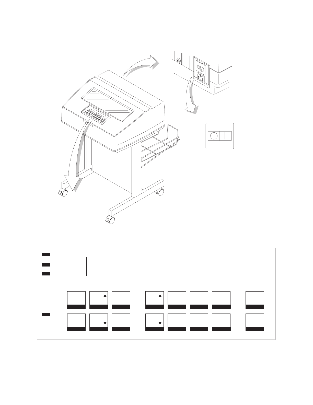
Controls and Indicators
Electrical Controls and Indicators, Cabinet Models (Figure 2)
Key or
Indicator
Power Indicator Lit when the printer is on.
Function
Ready Indicator Lit when the printer is in READY mode (on-line), no errors are pending, and the printer is
Processing Indicator Flashes when the printer is receiving data from the host.
Attention Indicator Flashes when an error occurs. After correcting the error, press Stop to turn off this LED.
Power Switch Applies power to the printer: (1 = on, 0 = off.) This switch is also a circuit breaker.
LCD The LCD (Liquid Crystal Display) displays printer status messages.
Start Puts the printer in the READY (on-line) mode. This key also clears fault conditions, exits
Stop Puts the printer in the NOT READY (off-line) mode. This key also silences the audible
Form Feed Advances paper to next Top-Of-Form, as defined by the current page length.
Set Top Of Form Sets TOF and moves paper downward from the tractor alignment notches to the print
Line Feed
View Press to move the current print position up to the tractor area for viewing. Press again to
Cancel Cancels a print job.
Eject / Restore Moves paper for viewing or tear-off. This key is configurable: refer to the
Menu If in the NOT READY mode, this key puts the printer in the PROGRAM mode. If the
Enter Selects the option displayed on the LCD. This action either sets a value, moves to the next
ready to process data. Off when the printer is in NOT READY mode (off-line).
program mode menus, moves paper back to print position after View is pressed, and
restores after an eject.
alarm, stops a Printer Test, and restores after an eject. Stop + Enter resets the printer.
position.
Moves paper up one line, as determined by current line spacing.
return paper to original print position.
Operator’s Guide
configuration menus are locked, the LCD indicates the operator panel is locked.
lower level of configuration, or starts a self-test. Stop + Enter resets the printer.
.
Return Returns to the next higher level of a configuration menu.
Micro
Micro ± In the NOT READY mode, moves the paper downward 1/72 inch (“micro-step” function).
Scroll
Scroll ± In the PROGRAM mode, this key moves to the previous menu (“Scroll” function).
Printer
Configuration
Stop + Enter Soft reset: load power on configuration in memory. Printer must be in NOT READY mode.
Scroll + Scroll ±
20
In the NOT READY mode, moves the paper upward 1/72 inch (“micro-step” function).
In the PROGRAM mode, this key moves to the next menu (“Scroll” function).
Prints the current configuration.
Toggles the lock on the configuration menus.
Maintenance Overview
Page 21
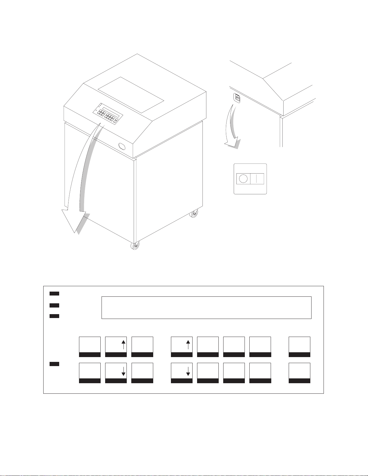
Power
Ready
Processing
(Off) (On)
Power Switch
LCD
Menu
Attention
Printer Configuration
Figure 2. Electrical Controls and Indicators, Cabinet Models
Maintenance Overview
Scroll
Scroll
Enter
Return
Micro
Micro
Line
Feed
View
Form
Feed
Set Top
Of Form
Start
Stop
Cancel
Eject/
Restore
21
Page 22

Electrical Controls and Indicators, Pedestal Models (Figure 3)
Key or
Indicator
Power Indicator Lit when the printer is on.
Function
Ready Indicator Lit when the printer is in READY mode (on-line), no errors are pending, and the printer is
Processing Indicator Flashes when the printer is receiving data from the host.
Attention Indicator Flashes when an error occurs. After correcting the error, press Stop to turn off this LED.
Power Switch Applies power to the printer: (1 = on, 0 = off.) This switch is also a circuit breaker.
LCD The LCD (Liquid Crystal Display) displays printer status messages.
Start Puts the printer in the READY (on-line) mode. This key also clears fault conditions, exits
Stop Puts the printer in the NOT READY (off-line) mode. This key also silences the audible
Form Feed Advances paper to next Top-Of-Form, as defined by the current page length.
Set Top Of Form Sets TOF and moves paper downward from the tractor alignment notches to the print
Line Feed
View Press to move the current print position up to the tractor area for viewing. Press again to
Cancel Cancels a print job.
Eject / Restore Moves paper for viewing or tear-off. This key is configurable: refer to the
Menu If in the NOT READY mode, this key puts the printer in the PROGRAM mode. If the
Enter Selects the option displayed on the LCD. This action either sets a value, moves to the next
ready to process data. Off when the printer is in NOT READY mode (off-line).
program mode menus, moves paper back to print position after View is pressed, and
restores after an eject.
alarm, stops a Printer Test, and restores after an eject. Stop + Enter resets the printer.
position.
Moves paper up one line, as determined by current line spacing.
return paper to original print position.
Operator’s Guide
configuration menus are locked, the LCD indicates the operator panel is locked.
lower level of configuration, or starts a self-test. Stop + Enter resets the printer.
.
Return Returns to the next higher level of a configuration menu.
Micro
Micro ± In the NOT READY mode, moves the paper downward 1/72 inch (“micro-step” function).
Scroll
Scroll ± In the PROGRAM mode, this key moves to the previous menu (“Scroll” function).
Printer
Configuration
Stop + Enter Soft reset: load power on configuration in memory. Printer must be in NOT READY mode.
Scroll + Scroll ±
22
In the NOT READY mode, moves the paper upward 1/72 inch (“micro-step” function).
In the PROGRAM mode, this key moves to the next menu (“Scroll” function).
Prints the current configuration.
Toggles the lock on the configuration menus.
Maintenance Overview
Page 23
Power
Ready
Processing
(Off) (On)
Power Switch
LCD
Menu
Attention
Printer Configuration
Figure 3. Electrical Controls and Indicators, Pedestal Model
Maintenance Overview
Scroll
Scroll
Enter
Return
Micro
Micro
Line
Feed
View
Form
Feed
Set Top
Of Form
Start
Stop
Cancel
Eject/
Restore
23
Page 24
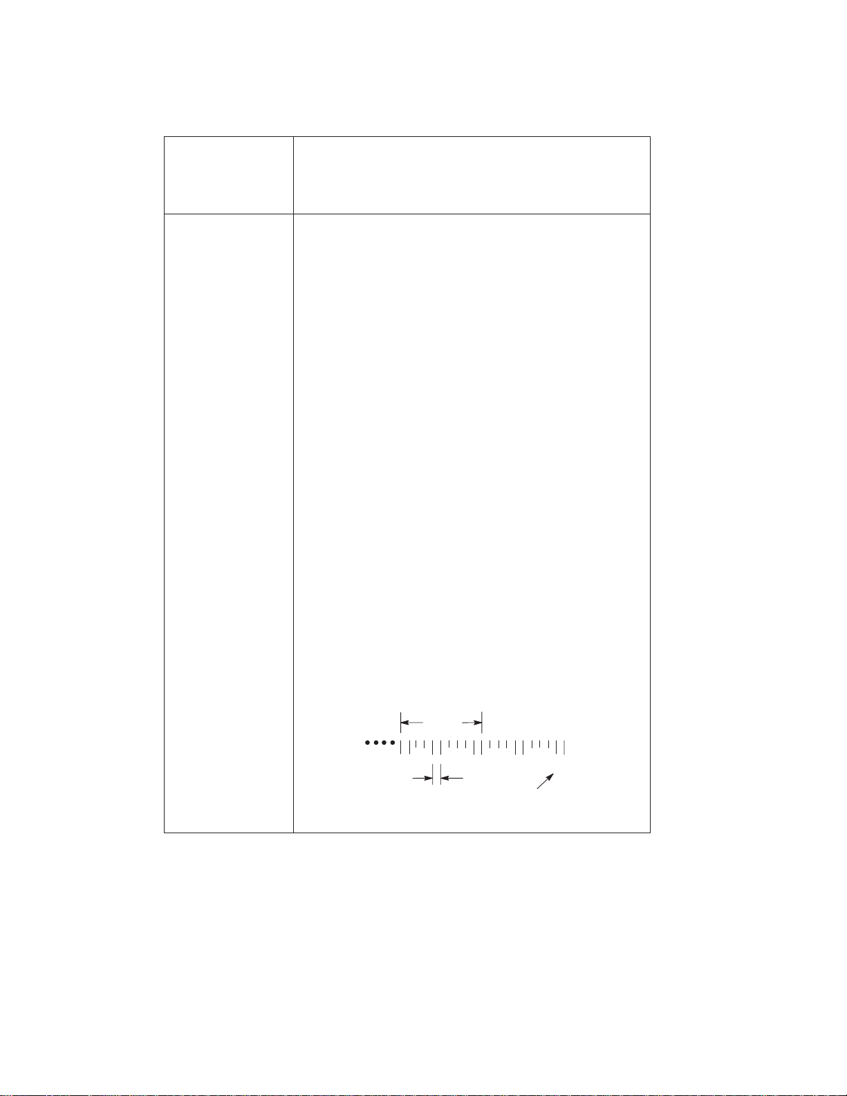
Mechanical Controls and Indicators, All Models (Figure 4)
Control or
Indicator
Forms Thickness
Lever
Paper Supports
Forms Thickness
Pointer and Scale
Tractors (2)
Tractor locks (2)
Horizontal
Adjustment Knob
Vertical Position
Knob
Ribbon Loading
Path Diagrams
Function
Sets the platen for paper and forms of different
thicknesses. Lever must be fully opened (raised) to load
or unload paper
Help prevent paper jams by supporting inner sections of
paper. Positioned manually by sliding them along shafts.
Indicates
at A for thin (single-part) forms, B for thicker forms, and
so on.
Hold and feed paper. Used to set side margin and
position paper horizontally.
Lock tractors in position.
Allows fine positioning of left print margin. Moves paper
and tractors left or right.
Used to set top of form or first line to be printed. Rotate
to move paper vertically. Works when Forms Thickness
Lever is open.
Instructions showing how to load the ribbon correctly.
One diagram is cast in relief on the shuttle cover
another is printed on the paper scale.
.
relative
thickness of forms/paper. Set this lever
, and
24
Paper Scale
A horizontal scale graduated in tenths of an inch, useful
for setting paper margins and counting text columns.
(See below.)
1 inch
110 20
0.1 inch
Column
Number
Maintenance Overview
Page 25
Left Tractor
Paper Scale
Paper
Supports
Horizontal
Adjustment
Knob
Tractor Lock
Ribbon Loading Path
Diagrams
Right Tractor
Tractor
Lock
Vertical
Position
Knob
Forms Thickness
Lever and Scale
Maintenance Overview
Forms
Thickness
Pointer
Figure 4. Mechanical Controls and Indicators
25
Page 26

Tools, Test Equipment, and Supplies
The tools and equipment required for field level maintenance of the printer
are listed below.
Item Part No.
6400 Line Matrix Printer Configuration
Utility Disk 63H7379
1–30 Inch-pound Torque Screwdriver 16F1661
ESD W
Feeler Gauge, .010 inch
Feeler Gauge, .011 inch
Feeler Gauge, .040 inch
Force Gauge, 20 lb 25F9687
Grip Ring Pliers 9900317
Lubricant, Bearing, IBM #20 117397
DIP Module Extracting Tool 9900764
Nut Driver, 1/4 inch
Nut Driver, 5/16 inch
Open End Wrench, 7/32 inch 1650843
Open End Wrench, 5/16 inch 9900005
PLCC Module Pick Extraction Tool 73G5523
PLCC Module Plier Extraction Tool 10G3902
Screwdriver, Philips, #1 73G5362
Screwdriver, Philips, #2 73G5363
Spring Hook, Heavy Duty
Tie Wraps 75X5972
Torque Screwdriver Adapter 39F8449
Torque Screwdriver Hex Adapter 3/32 inch 39F8451
Torque Screwdriver Hex Adapter 5/32 inch 39F8450
Torque Screwdriver Hex Adapter 3/16 inch 39F8455
Torque Screwdriver Hex Adapter 5/64 inch 16F1663
Torx** T-10 Bit 83F2834
rist Strap 6405959
26
Maintenance Overview
Page 27

2
Installation
Installation and configuration of the printer are covered in the
6400 Line Matrix Printer Set-Up Guide
Installation, operation, and replacement parts for the optional coax/twinax
interface are covered in the
Installation and Operation Guide
Installation, configuration, and troubleshooting of the Network Print Server
are covered in the following documents:
♦
IBM Network Print Server Ethernet Administrator’s Guide
Form No. S246–0111
Coax/Twinax Multi–Platform Interface Option
, Form No. S544–5640
, Form No. S246–0149.
,
♦
IBM Network Print Server Token-Ring Administrator’s Guide
Form No. S246–0112
♦ The
Network Print Server Technical Reference Manual
diskette that comes with the Network Print Server. This “softcopy”
document is in Adobe Acrobat Reader format.
is included on a
,
27Installation
Page 28

28 Installation
Page 29
3
Preventive Maintenance
Cleaning the Printer
Aside from normal replenishment of paper and ribbons, the only preventive
maintenance required for the printer is periodic cleaning.
Because operating conditions vary widely, the user must determine how often
to clean the printer.
There is no guarantee that the user will clean the printer regularly, however,
so you should clean the printer whenever you are called to service it.
DANGER:
<2> Switch off printer power and unplug the printer power cord before
cleaning the printer.
ATTENTION
Do not use abrasive cleaners, particularly on the window.
Do not drip water into the printer. Damage to the equipment will result.
Do not spray directly onto the printer when using spray solutions
(spray the cloth, then apply the dampened cloth to the printer).
Do not vacuum circuit boards.
Preventive Maintenance
29
Page 30

Cleaning the Exterior
1. Power off the printer.
2. Disconnect the AC power cord from the power source.
3. Wipe the outside of the enclosure with a clean, lint-free cloth dampened
(not wet) with water and a mild detergent or window cleaning solution.
4. Dry the enclosure with a clean, lint-free cloth.
5. Clean the inside of the printer, as described below.
Cleaning the Interior
1. Power off the printer.
2. Disconnect the AC power cord from the power source.
3. Open the printer cover.
4. Remove paper from the printer.
5. Remove the ribbon.
6. Using a soft-bristled, non-metallic brush, wipe paper dust and ribbon lint
off the tractors, shuttle cover assembly, base casting, and ribbon guides.
Vacuum up the residue.
7. Wipe the splined shaft and the ribbon guides with a soft cloth.
8. Vacuum up dust or residue that has accumulated inside the lower
cabinet.
9. Wipe the interior of the lower cabinet with a clean, lint-free cloth
dampened with water and a mild detergent or window cleaning solution.
10. Dry the cabinet interior with a clean, lint-free cloth.
11. Clean the shuttle frame assembly, as described below.
30
Preventive Maintenance
Page 31

Shuttle
Cover
Assembly
Base
Casting
Splined
Shaft
Tractor
NOTE: Cabinet model shown.
Procedure is the same for
pedestal model.
Forms
Thickness
Ribbon
Guide (2)
Lever
Figure 5. Cleaning Inside the Cabinet or Top Cover
Cleaning the Shuttle Frame Assembly
1. Remove the shuttle cover assembly (page 209).
2. Remove the shuttle frame assembly (page 249).
3. Remove the paper ironer (page 236).
CAUTION:
<2> Over time the upper edge of the paper ironer can become sharp. To
avoid cutting yourself handle the paper ironer on the sides.
4. Wipe the paper ironer with a soft cloth to remove lint, ink, and paper
residue.
5. Install the paper ironer (page 236).
6. Remove the hammer bank / ribbon mask cover assembly (page 206).
Preventive Maintenance
31
Page 32

ATTENTION
The thin plate (ribbon mask) of the hammer bank cover assembly is
fragile. Be careful not to over-bend or kink the ribbon mask when
handling and cleaning the hammer bank cover assembly.
7. Using a clean soft cloth, wipe the hammer bank cover and ribbon mask
to remove lint, ink, and paper residue. Clean the holes in the cover strips.
Carefully wipe between the hammer bank cover and the ribbon mask
(early models).
ATTENTION
Do not use any solvents or liquids to clean the hammer tips. Clean the
hammer tips gently—too much pressure can chip hammer tips.
8. Using a stiff, non-metallic brush (such as a toothbrush), gently brush the
hammer tips to remove lint and ink accumulations. (See Figure 6.)
Vacuum up any residue.
6400–004/04P
NOTE:
hammer bank shown.
Procedure is the same for
Hammer
Tip
all hammer banks.
32
Figure 6. Cleaning the Hammer Tips
ATTENTION
The hammer bank contains a strong magnet. To prevent damage to the
hammer tips, do not let the hammer bank cover assembly snap into
place as the hammer bank magnet attracts it. Any impact of the cover
against the hammer bank can break hammer tips.
9. Install the hammer bank / ribbon mask cover assembly (page 206).
10. Install the shuttle frame assembly (page 249).
11. Install the shuttle cover assembly (page 209).
12. Clean the card cage fan assembly, as described below.
Preventive Maintenance
Page 33

Cleaning the Card Cage Fan Assembly
1. Cabinet Models: Remove the paper guide assembly (page 235).
Pedestal Model: Remove the top cover assembly (page 210).
2. Vacuum the card cage fan assembly and surrounding areas to remove
paper particles, dust, and lint.
3. Cabinet Models: Install the paper guide assembly (page 235).
Pedestal Model: Install the top cover assembly (page 210).
4. Close the printer cover.
5. Connect the AC power cord to the power source.
NOTE: Cabinet model shown.
Procedure is the same for
pedestal model.
Card Cage
Fan Assembly
Preventive Maintenance
Figure 7. Cleaning the Card Cage Fan Assembly
33
Page 34

34
Preventive Maintenance
Page 35

4
Principles of Operation
Line Matrix Printing
The printer creates characters and graphics by printing patterns of ink dots
on paper, an entire line at a time. This technique is called line matrix printing.
Every text character is stored in printer memory as a pattern of dots on a
logical grid called the dot matrix. (See Figure 8.) The ink dots are made by a
row of small hammers mounted on a shuttle that sweeps rapidly back and
forth. Printer logic circuits divide every line of incoming data into horizontal
dot rows. The hammers put dots at the required positions for the entire
by striking an inked ribbon and the paper.
line
0.00835 inch
0.01389 inch
First row and column of next
character line (at 6 LPI)
0.02 inch
112Column No.
0.10 inch
First row and column
of next character column
(at 10 cpi)
Lowest descender dot line
Figure 8. A Dot Matrix
Principles of Operation
35
Page 36

When the shuttle reaches the end of a sweep, it reverses direction, the paper
is advanced one dot row, and the hammers print the next row of dots as the
shuttle sweeps in the opposite direction. After a line of characters is printed,
hammer action stops and the paper advances to the first dot row of the next
print line. The number of dot rows allowed for line separation depends on the
vertical line spacing the user selects.
The dot matrix patterns of text characters vary according to the font the user
selects. For example, in the data processing (DP) font at a line spacing of six
lines per inch (lpi), a dot matrix contains 12 dot rows from the top of one
character line to the top of the next. (See Figure 8 and Figure 9.) At eight lpi
there are nine dot rows per character line, at nine lpi eight dot rows per
character line, and so on.
Each individual hammer spring forms more than one character as the shuttle
moves horizontally. This principle is illustrated in Figure 10.
One
Text
Line
Direction of Shuttle Movement
Dot
Row
Start
1
2
3
4
5
6
7
8
*
9
**
10
11
Number of rows determined by line spacing
n
1
2
* This row is used only for lowercase descenders
** This row is used for underlining and lowercase descenders
Paper
Feed
Direction
36
Figure 9. Standard Character Formation
Principles of Operation
Page 37

Succesive Hammer Strokes Per Scan
Shuttle
Scan
1
2
3
4
5
6
Dot
Row
1
1
2
1
2
3
1
2
3
4
1
2
3
4
5
1
2
3
4
5
6
1 13 135 1 357 13579
******
1
2
3
4
5
6
7
7
*
Figure 10. Action of One Hammer Spring in Text Printing
Principles of Operation
Even column dot centers within the printed character
area and character space hammer positions are not
illustrated in this diagram.
NOTE:
= Hammer Released and Dot Printed
= Hammer Not Released; No Dot Printed
37
Page 38

Printing Mechanism
While the principles of line matrix printing are easy to state, the act of printing
dots accurately from a rapidly oscillating shuttle onto a vertically moving
piece of paper requires complex timing and coordination between printer
logic and the printing mechanism. The printing mechanism consists of the
shuttle frame assembly, the ribbon transport system, and the paper transport
system.
Shuttle Frame Assembly
The central element of the printing mechanism is the shuttle frame assembly,
which houses the hammer bank assembly and the shuttle drive motor. (See
Figure 11.)
Shuttle Frame
Assembly
Hammer Bank Assembly
Counterweight Assembly
Connecting Rod
Guide Shaft
Shuttle Drive Motor
38
Figure 11. Shuttle Frame Assembly
Principles of Operation
Page 39

Hammer Bank Assembly
The hammer springs are grouped in comb-like assemblies mounted on a
solid hammer bank. Both the number of hammer springs per hammer spring
assembly and the number of hammer spring assemblies on the hammer
bank vary according to printer model:
♦ 6400–004/–04P/–005/–05P/–050/–P50: seven 4-hammer assemblies, for
a total of 28 hammer springs
♦ 6400–008/–08P/009/–09P: seven 7-hammer assemblies, for a total of 49
hammer springs
♦ 6400–010, –10P: six 10-hammer assemblies, for a total of 60 hammer
springs
♦ 6400–012/–014: seven 13-hammer assemblies, for a total of 91 hammer
springs
♦ 6400–015: six 17-hammer assemblies, for a total of 102 hammer springs
Shuttle Drive Motor
The shuttle drive motor is built into the shuttle assembly casting and drives
two connecting rods on a crankshaft. (See Figure 11.) The small end of one
connecting rod attaches to the hammer bank; the small end of the other
connecting rod attaches to a counterweight frame surrounding the hammer
bank. (The hammer bank and the counterweight constitute the shuttle
assembly.) The rotary motion of the shuttle drive motor converts to linear and
opposing motion of the hammer bank assembly and the counterweight, in an
arrangement similar to that of a horizontally-opposed gasoline engine.
Mechanically, this design achieves the same benefits as this type of engine:
perfect primary balance, low vibration, and durability.
Each hammer spring is a stiff leaf spring with a cylindrical tungsten carbide
tip on the free end. (See Figure 12.) A permanent magnet is imbedded along
the length of the hammer bank and acts on the hammer springs through
individual pole pieces. The pole pieces magnetically attract and hold the free
end of the hammer spring under tension. This is called the retracted state.
Principles of Operation
39
Page 40

Tungsten
Carbide
Hammer Tip
Hammer Spring Assembly
NOTE:
6400–004/04P
hammer bank shown.
Alignment Pin
Hammer Bank Assembly:
Coils, Magnet, Pole Pieces,
Hammer Spring Assemblies
40
Figure 12. Hammer Springs and Hammer Bank (Detail)
Two electromagnetic coils are mounted behind each hammer and wound
around each pole piece. The coils are normally de-energized. When hammer
driver logic determines that the hammer must print a dot, a current pulse
energizes the coils. The polarity of the resulting magnetic field opposes the
field of the permanent magnet, canceling its effect and releasing the hammer.
The hammer springs forward, strikes the ribbon and paper, and leaves a dot
impression of the hammer tip on the paper.
While the hammer is in flight the coil is de-energized and its field collapses.
After striking the ribbon and paper, the hammer rebounds and the permanent
magnet recaptures it. When the shuttle reaches the end of a sweep, it
reverses direction, the paper is moved up one dot row, and the hammer
springs print the next row of dots as the shuttle sweeps in the opposite
direction.
Principles of Operation
Page 41

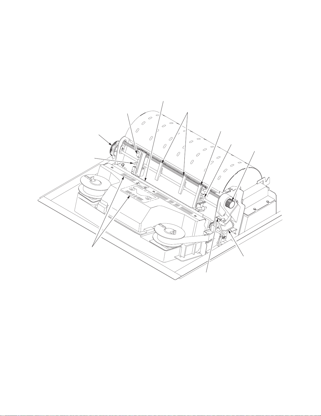
Paper Transport System
Tractor
Support
Shaft
Horizontal
Adjustment
Knob
Shuttle Cover
Assembly
Paper
Supports
Tractors
Paper Path
Splined
Shaft
Paper Feed Timing
Belt (Under the cover)
Vertical Adjustment
Knob and Splined
Shaft Pulley
A two-phase DC stepper motor, directed by the EC on the controller board,
drives two tractor sprockets by means of a toothed belt and splined shaft
pulley arrangement. The stepper motor permits extremely accurate
incremental vertical paper movement. This drive configuration is designed for
continuous, fan-folded paper three to 17 inches wide and one to six sheets
thick. For reverse paper feeding, the platen open motor opens and closes the
platen via a toothed belt. Opening the platen prevents paper jams when
paper direction is reversed—that is, paper is moved downwards—in order to
view the print area, set top of form, or allow applications to overprint forms.
Paper is positioned horizontally using the tractors and the horizontal
adjustment knob. Each tractor engages paper perforations with six sprocket
pins and locks in place with a friction lock. The horizontal adjustment knob
allows vernier positioning of the left print margin.
Paper can be positioned vertically by hand with the vertical adjustment knob.
Principles of Operation
Figure 13. Paper Transport System
41
Page 42

Ribbon Transport System
Left Ribbon Guide
(Not Shown)
Hub Locking
Latch
Ribbon
Spool
Ribbon Hub
Ribbon
Motors
Right Ribbon Guide
Ribbon
Figure 14. Ribbon Transport System
An inked ribbon winds and unwinds continuously on a pair of spools latched
to hubs that are driven by the ribbon motors. The hubs and spools are offset
vertically to equalize ribbon wear and prolong ribbon life. The ribbon motors
operate only when the shuttle assembly is moving. Ribbon motion reverses
when a metal strip at either end of the ribbon crosses the left or right ribbon
guide, completing a circuit that causes both motors to reverse direction.
Constant ribbon tension is maintained by controlling each motor with a drive
or drag circuit. While the shuttle assembly is in motion, one motor acts as a
drive motor, pulling the ribbon against the resistance exerted by the other
motor—the drag motor. This system maintains a constant motor speed and
ribbon tension.
42
Principles of Operation
Page 43

Logical Control of the Printer
The printer is divided into four functional elements: the operator panel, the
CMX controller board, the power supply, and the print mechanism. See
Figure 15.
AC
Input
Circuit
Breaker
Card Cage
Fan
ON/OFF
SWITCH
Line 1
CHASSIS
GND
Line 2 / Neutral
CMX Controller Board
AC
POWER
Power Supply
Board
EIA–232–E
Serial I/O
+5 V Remote
Power
Operator
Panel
Parallel
I/O
Shield
GND
Cabinet
Exhaust
Fan
(Cabinet
models
only)
Platen
Motor
Paper Motion
Detector
Paper Out
Detector
Left Ribbon
Guide
Left Ribbon
Motor
Print Mechanism
Principles of Operation
Flex Circuits:
Shuttle
Assy
Terminator Board
Shuttle Motor
Hammer Bank Board
MPU
Shuttle Assembly
Hammer Bank
Fan
Figure 15. Functional Elements of the Printer
Paper Feed
Motor
Platen Open
Switch
Right Ribbon
Guide
Right Ribbon
Motor
43
Page 44

Operator Panel
The user communicates with the printer by pressing keys on the operator
panel. The keys are momentary contact switches. The operator panel
processes and sends key closure information to the controller board and
displays information from the controller on the LCD. A status indicator next to
the LCD also conveys printer status information to the user.
The LCD, status indicator, and keys are mounted on a printed circuit board
assembly enclosed in a protective housing.
Operator Panel
CMX Controller Board
♦ Data
♦ Control
♦ Key
(Switch)
Closures
J110
44
Figure 16. Operator Panel Functional Overview
Principles of Operation
Page 45

CMX Controller Board
The heart of the printer is the CMX controller board, which monitors and
directs all printer functions. The controller board receives and processes all
data from the host computer, builds the printable images, controls all motors,
and drives the hammer springs. Except for the power supply and final
hammer drive circuits, all logic and drive circuitry for the printer are contained
on the controller board.
The CMX controller board consists of two functional units: the Data Controller
(DC) and the Engine Controller (EC).
The DC is responsible for:
♦ Host I/O
♦ Operator I/O
♦ Security Interface
♦ Print Image Generation
♦ Overall High Level (Logical) Control
The EC is responsible for:
♦ Print Mechanism Operation
♦ Print Mechanism Fault Monitoring
♦ Power Shutdown/Power Saving Modes
The EC and DC communicate through semaphore registers. The DC
receives host and operator input and returns dot images and LCD messages
to buffers in memory. Image data are passed to the EC upon request, are
processed, then sent to the hammer bank. The EC synchronizes paper,
ribbon, platen, and shuttle motion as it feeds dot data to the hammer drivers.
Figure 17 summarizes this architecture.
Principles of Operation
45
Page 46

25 or 40 MHz
Expansion
Port
RS–232
Diagnostic
Port
Control
Panel
RS–232/422
IEEE–1284
(Parallel)
Fault
Sensors
Paper
Feed
Ribbon
TTL
Diagnostic
Port
46
Shuttle
Platen
Hammer
Drive
Figure 17. CMX Controller Board Block Diagram
Principles of Operation
Page 47

Data Controller
The data controller (DC) consists of the following elements:
♦ 68EC030 microprocessor
♦ Two flash SIMM sockets, used for up to 30MB of program memory
(Base configuration: 1MB flash in bank 0)
♦ Two DRAM SIMM sockets, used for up to 32MB of data memory
(Base configuration: 1MB DRAM in bank 0)
♦ 8K x 8 Non-Volatile Battery-Backed static RAM (NVRAM) for storage of
configuration and system statistical data
♦ VX ASIC (Application-Specific Integrated Circuit)
♦ Host I/O Drivers/Termination
68EC030 Microprocessor
A Motorola 68EC030 microprocessor serves as the processor of the DC unit.
This processor runs at 25 MHz on all models except the 6400–050, –P50,
–010, –P10, and –015.
On 6400–050, –P50, –010, –P10, and –015 printers the 68EC030 processor
runs at 40 MHz and the controller board on these models is called the “CMX
040.” The CMX 040 controller is backward compatible with any 6400 Series
printer, but must be used in 6400–050, –P50, –010, –P10, and –015 printers.
Although this chapter refers to the DC microprocessor as simply the “030,”
remember that two different clock speeds are available.
Flash Memory
The DC stores program and emulation code in flash memory. Flash memory
is erasable, non-volatile, and significantly faster than a disk drive.
The DC uses AMD 5.0V-only flash memory, which does not require higher
programming and erasing voltages on the board (it has an internal charge
pump to make these voltages itself). This memory supports at least 100,000
write/erase cycles. The flash memory is 32 bits wide. It is byte, word, and
double word readable, but is always written as double words.
Two 80-pin SIMM sockets are provided for flash memory. Up to 30MB of
flash (total), organized as up to four banks, may be installed in the two
sockets on the controller board. The boot code for the 68EC030 processor
must reside in bank 0.
Programs stored in flash memory are changed through the parallel or serial
port.
Principles of Operation
47
Page 48

DRAM
System DRAM is used for program variables, image buffers, and input
buffers. All DRAM supports page mode operation and is addressable by
individual byte.
Two standard 72-pin DRAM SIMMs are used for expansion memory. The DC,
through the VX ASIC, may address up to 32MB of DRAM in four banks.
NVRAM
A 8K x 8 bit Non-Volatile battery-backed static RAM (NVRAM) device
provides for the storage of configuration and system statistical data.
VX ASIC
The VX is a multifunction custom gate array ASIC containing all the logic for
the DC that is not contained in the 68EC030 processor. The VX provides the
following services:
♦ Memory Access Controller
♦ DRAM Controller
♦ Flash Controller
♦ Two DMA Channels
♦ Operator Panel Interface
♦ “Dot Plucking” and Adjacent Dot Checking
♦ “Cajun” Bus Interface
♦ Host I/O and Diagnostic Port
Memory Access Controller All 030 addresses go through the VX ASIC. The VX handles all address decoding, chip selects, DTACKs, and so on.
DRAM Controller The VX supports up to four banks of page mode DRAM. FLASH Controller The VX supports up to four banks of flash memory. DMA Channels The VX provides two channels for direct memory access.
These channels move data from the host interface or expansion bus to the
DRAM and vice versa. One address is an I/O address, the other is a memory
address with auto-increment.
Operator Panel Interface The VX operator panel interface consists of five lines: serial clock, serial data, and three select lines. It is the VX that handles all parallel-to-serial (and vice versa) conversion to and from the panel, as well as any special timing needed when toggling select lines, etc.
48
Principles of Operation
Page 49

“Dot Plucking” and Adjacent Dot Checking “Dot Plucking” is a specialized
DMA function that removes dot data from a dot image buffer in DRAM in a
programmable manner, serializes it, and sends it to the hammer bank. This
function is actually controlled by the EC (see page 50), which has access to
the VX through the “Cajun” Bus Interface.
“Cajun” Bus Interface The “Cajun” bus interfaces the DC, the EC, and the
expansion port. The EC uses this bus to access DC resources, including the
semaphore registers. (The semaphore registers are the primary
communications path between the EC and DC.)
Ports The VX ASIC controls the following I/O functions:
♦ Interface to an IEEE 1284 Level 2 host
♦ Interface to RS–232E serial host
♦ Interface to RS–422 serial host
All the circuitry required for these host types is provided on the CMX board,
except for the drivers themselves, ESD protection, and terminations.
Host I/O Drivers and Termination
Beyond the 030 processor and VX ASIC, additional support circuitry
completes the serial and parallel interfaces. These circuits include:
♦ RS–232 drivers and receivers. These circuits use internal charge pumps
to eliminate the need for 12V power.
♦ RS–422 differential drivers and receivers
♦ Parallel port pull up and pull down terminating resistors are DIP-socketed
for easy removal and installation.
All interface ICs and terminations have the following characteristics:
♦ Provide ESD protection to 15KV for all inputs.
♦ Less than 0.05V common mode ripple, measured at the power and
ground of the interface ICs.
♦ Less than 0.02V common mode ripple, measured between chassis
ground and the ground pins of the interface ICs.
♦ Greater than 200V/ms slew rate for all outputs.
Principles of Operation
49
Page 50

Engine Controller
The engine controller (EC) consists of four main elements:
♦ 80C166 Microcontroller
♦ 128KB 5.0V-only FLASH program memory, organized as 64K x 16 bits.
This memory is not expandable.
♦ MECA (Mechanism Engine Control ASIC)
♦ Analog drive circuitry
80C166 Microprocessor
The Siemens SAB 80C166 is a high-integration microcontroller. It has many
features that suit it extremely well to real-time control applications. This
controller and the MECA ASIC provide the functionality of three separate
processors used in earlier controller board architectures. In this manual, the
80C166 is referred to as either the EC or the 166.
The 166 used on the CMX board runs at 20MHz and is housed in a 100-pin
metric rectangular flat pack.
Bus Configuration The 166 bus is configured for 18-bit address, 16-bit data,
non-multiplexed and segmented operation. The flash memory runs with zero
wait states. An external PAL is used for address decoding.
Power Reduction The 166 chip has two power reduction modes: idle and Energy Star. Idle mode is not used. In Energy Star mode, +48V and all motors are de-energized, but the 166 operates as normal.
EC Flash Memory The EC stores all boot code, program code, and tables in its own local flash memory. This flash is organized as 64K x16 bits and uses the same technology as the DC flash: it is + 5.0V-only and is rated for a minimum of 100,000 write/erase cycles. EC memory is fixed; it is soldered to the controller board. Its contents can be updated through the DC (through the serial or parallel ports). At run time, the EC also stores tables in shared DRAM, which is accessed through the Cajun bus.
MECA ASIC
in the MECA to control many printer motor functions. The MECA is a custom
gate array, specifically designed to drive this system.
Analog Drive Circuitry
The analog drive functions convert 48 and 8.5 volts into the power used to
drive the motors and hammers in the printer. Sensors are used to monitor the
operation and status of critical components within the printer.
The 166 uses numerous counters, PWM generators, and FIFOs
50
Principles of Operation
Page 51

The printer uses five motors: two ribbon drive, one paper feed, one platen
open, and one shuttle motor. The shuttle motor is a brushless DC motor
driven by current control. The MPU encoder is used as feedback for motor
commutations, hammer fire timing, and motor stall detection. The paper feed
motor is a DC stepping motor driven by current control. The paper feed motor
may be driven in full, half, or microsteps, depending on print requirements.
The ribbon system uses two DC stepping motors that alternate drive and
drag roles when the ribbon reaches turnaround. The drive ribbon motor is
microstepped in voltage mode, while the drag motor is loaded and monitored
to maintain correct linear speed and tension. The platen motor is driven in
current mode and can be full or half stepped. The overall current level may
be reduced for standby modes.
The paper feed, ribbon drive, and shuttle motors are driven in control loops
containing power MOSFETs, voltage and current sensors, the MECA ASIC,
and the EC processor. The platen open motor is driven by a stepping motor
controller IC and the EC processor.
Control of the hammer drive is split between the controller board and the
hammer bank. Common circuits are located on the controller board, while
hammer specific circuitry is contained on the hammer bank. The EC uses the
MECA ASIC on the controller board to set timing and upper drive profiles for
hammer fire events. The controller also contains diagnostic circuitry for the
hammer system. The hammer bank contains HBA ASICs that interpret fire
commands and data from the MECA and VX ASICs. The HBAs control lower
drive MOSFETs on the hammer bank. These determine which hammers will
participate in a fire event generated by the controller’s upper drive.
Power Supply Board
The printer power supply is contained on a printed circuit board mounted in
the card cage. The power supply automatically senses and adjusts to any
commercial electrical system that provides AC mains potential in 50 or 60
Hertz systems. In other words, the printer is fully operational from available
commercial power anywhere in the world.
The power supply converts alternating current (AC) to direct current (DC) at
three voltage levels and sends the DC voltages to the controller board. The
controller board distributes all DC power to the logic and electromechanical
circuits.
AC Power
The power supply operates on AC voltages ranging from 88 to 270 V. It can
tolerate variations in frequency of 47 to 63 Hz. The power supply is designed
Principles of Operation
51
Page 52

to withstand an AC input overvoltage of 300 VAC for one second with no
degradation of DC output voltage or damage to printer circuits.
DC Power
The power supply board contains two DC power supply systems for the
printer. The first is a + 5 V bus for logic. The second consists of + 48 V and
+ 8.5 V buses for the hammer bank and all motors.
The + 5 V supply has an isolated return line that connects to the + 48 V
return at the printer load. Both returns are tied together in a single-point
ground. The + 5 V power supply has its own inverter, separate from the + 48
V and + 8.5 V outputs.
There is an opto-isolated input on the power supply that will shut down and
latch off the + 48 V and + 8.5 V supplies unless it is pulled up to 5V with a 1K
Ω resistor. This resistor is mounted on the controller board and may be pulled
down or disconnected by software or internal cable interlocks. The + 5 V
output will remain stable for reporting and latching the fault condition. The
return for this signal is the + 5 V return. In addition, this shutdown circuit
discharges and latches the + 48 V down to a level lower than 15 V in less
than 200 milliseconds and requires recycling of the circuit breaker (On/Off
switch) to reset the latch.
Loss of + 48 V is seen by the EC and reported as a fault.
Printer Interface
The printer interface is the point where the data line from the host computer
plugs into the printer. The printer interface processes all signals and data to
and from the host computer.
The printer supports supports a number of standard and optional interfaces
to the host:
♦ Centronics parallel (standard)
♦ IEEE 1284 parallel (standard)
♦ EIA-232-E serial (standard)
♦ EIA-422-B serial (standard)
♦ Coaxial/twinaxial “Expansion-CT” (optional)
♦ Ethernet10Base-2 or 10Base-T adapter (optional)
52
Principles of Operation
Page 53

Graphics
Selection of the input/output interface is controlled by configuration menus
accessed at the operator panel. It is possible to physically connect more than
one interface, but only one interface at a time can be used electrically.
The Code V programming language (a QMS graphics emulation) and the
IGP programming language (a Printronix IGP emulation) are options that
install in flash memory on the CMX controller board.
These programming languages simplify the job of creating forms, bar codes,
logos, expanded characters, and other graphics. These languages enable
the printer to print sideways, upside down, and to make forms combining
graphics, alphanumeric data, and bar codes—all in a single pass.
Documents explaining configuration, operation, and programming are
included with each option.
Principles of Operation
53
Page 54

54
Principles of Operation
Page 55

5
Troubleshooting
Introduction
This chapter lists fault messages and symptoms, and provides procedures
for troubleshooting printer malfunctions.
Always have the
troubleshoot because this manual does not cover printer operation or
configuration. You must operate the printer to check its performance, and
sometimes you may have to reconfigure it.
Troubleshooting Aids
Troubleshooting is faster and more effective if you understand the equipment
and make use of all available tools.
This manual provides a number of troubleshooting aids to help you isolate
printer malfunctions:
♦ Start of Call Page 56.
♦ Troubleshooting Display Messages Page 57.
♦ Message List Page 58.
♦ Troubleshooting Other Symptoms Page 66.
♦ General Symptom List Page 67.
♦ Troubleshooting Procedures Page 70.
♦ Communications Failures Page 133.
Operator’s Guide
. . . . . . . . . . . . . . . . . . . . . . . . . . . . . .
. . . . . . . . . . . . . . . . . . . . . . . . . . . .
and the
. . . . . . . . . . . . . . . . . . . .
. . . . . . . . . . . . . . . .
Setup Guide
. . . . . . .
. . . . . . . . .
. . . . . . . . . . . . . .
handy when you
♦ Operator Print Tests Page 135.
♦ Customer Engineer (CE) Tests Page 138.
♦ Hex Code Printout Page 145.
♦ ASCII Character Set Page 147.
♦ The Power On Sequence Page 151.
♦ Appendix A: Wire Data Page 293.
. . . . . . . . . . . . . . . . . . . . . .
. . . . . . . . . . . . . . . . . . . . . . .
. . . . . . . . . . . . . . . . . . . . . .
. . . . . . . . . . . . . . . . .
. . . . . . . . . . . . . . . . . . .
. . . . . . . . . . . .
55Troubleshooting
Page 56

Start of Call
Are you here because of an error
message?
In the next step, you will observe the
operator panel for the following
sequence of events (retry as required):
1. All LEDs on and black squares on
display.
2. All LEDs off and display blank.
3. TESTING HARDWARE
PLEASE WAIT message on display.
Power on the printer.
Did steps 1, 2, and 3 occur?
NO
Did the fans
come on
after 10
seconds?
NO
YES
NO
Press Stop.
Press Print
Configuration.
Press Start.
Does machine
configuration
print?
YES
YES
NO
Go to Troubleshooting
Display Messages
Did the fans
come on?
NO
Go to
Printer does not
complete IML,
page 122.
YES
Go to the Operator
Panel section of
T
YES
able 3, page 67.
Did Power
Ready LEDs
come on after
10 seconds?
Go to
Printer does not
complete IML,
page 122.
, page 57.
NO
and
YES
IML was
successful.
Other
symptoms
are listed
able 3,
in T
page 67.
The Operator
Panel is not
functioning (see
able 3, page 67)
T
—OR—
Printer does not
complete IML,
page 122.
Did ANY of
steps 1 thru
3 occur?
NO
Go to No power, and the
operator panel is blank,
and the card cage fan is
not running
YES
, page 1
19.
Are there black
squares on the
operator panel?
NO
Go to Printer does
not complete IML,
page 122.
YES
Go to Black squares on
operator panel display,
page 1
14.
56 Troubleshooting
Page 57

Troubleshooting Display Messages
DANGER:
<3> Hazardous voltages are present in the printer with the power cord
connected to the power source. Switch off printer power and unplug the
printer power cord before proceeding.
<4> Do not connect or disconnect any communication port, teleport,
attachment connector, or power cord during an electrical storm.
<5> Power off the printer and disconnect the power cord before connecting
or disconnecting communication port, teleport, or attachment cable
connector.
If a fault condition occurs in the printer, four things happen:
♦ The Attention indicator on the operator panel flashes on and off.
♦ If enabled, the audible alarm sounds. (Press Stop to silence the alarm.)
♦ A message describing the fault condition appears on the LCD.
♦ Certain
the error log. The error log is a buffer in NVRAM that stores up to 50
messages as a list. The most recent message is stored at the top of the
list, the oldest message at the bottom of the list. If more than 50
messages occur before the log is cleared, the oldest messages are
deleted, so the log never contains more than 50 messages. You can print
the error log and clear it. (See page 135.)
The LCD displays two kinds of printer conditions:
An
♦
supplies, clears paper jams, corrects a problem of communication
between the printer and host computer, etc.
A
♦
Unit check conditions are either
Unit Check
Attention
Unit Check
conditions (see below) are automatically recorded in
condition halts printing until the operator replenishes
condition is a failure detected by self-test and fault circuitry.
recoverable
or
unrecoverable
.
57Troubleshooting
Page 58

Recoverable
a.
electromechanical print mechanism that may be temporary and
correctable by cycling power. The printer tries a number of times to
correct the condition before posting the message to the operator
panel. The first thing to do in such cases is to power the printer off,
wait 15 seconds, then power the printer back on. If the message
reappears, classify the check condition unrecoverable.
unit check conditions are errors detected in the
Unrecoverable
b.
overcurrent, component failure, or microcode failures that prevent
printing until the conditions are corrected. Unrecoverable conditions
require that the printer be powered off and the condition corrected
before powering the printer back on.
Clearing Error Messages
Refer to the Message List below, which lists the display messages
numerically and alphabetically and directs you to a troubleshooting
procedure.
After correcting an error, press the Stop key to clear the message and return
the printer to the NOT READY state. Press Start to resume printing.
(If an error is not cleared, the printer will try to print again but will display
another error message until the error is cleared.)
Operator Panel Message
unit check conditions are “hard” failures such as
Table 2. Message List
Troubleshooting
Procedure
001 END OF FORMS
LOAD FORMS
002 FORMS JAMMED
CLEAR JAM AND RELOAD FORMS
003 FORMS EJECTED
PRESS EJECT/REST
004 VIEW FORMS
PRESS VIEW KEY
006 HOST SYSTEM REQUEST A
007 FM HEADER ERROR Page 72
58 Troubleshooting
ORE
TTENTION Page 72
Page 70
Page 70
Page 72
Page 72
Page 59

Operator Panel Message
Troubleshooting
Procedure
008 HOLD PRINT TIMEOUT
PRESS ST
009 INV
010 P
01
1 SCS COMMAND ERROR
012 STRUCTURED FIELD ERROR Page 73
013 ACTIVATE LOST Page 74
014 INV
015 COMMUNICA
CHECK CABLE
016 INVALID COMMAND Page 75
017 ST
CHECK ST
018 ST
CHECK ST
ART
ALID KEY PRESS
ARAMETER ERROR
ALID ACTIV
ACKER JAM
ACKER
ACKER FULL
ACKER
ATE Page 74
TION CHECK
Page 72
Page 72
Page 73
Page 73
Page 75
Page 76
Page 76
019 ST
CHECK ST
021 RECEIVE BUFFER OVERRUN
VERIFY CONFIGURA
022 UNIT ADDRESS NOT RECEIVED
CHECK PRINTER ADDRESS
024 SERIAL LINE PARITY ERROR
VERIFY CONFIGURA
025 SERIAL FRAMING ERROR
VERIFY CONFIGURA
026 HEX DUMP MODE Page 79
027 COMMUNICA
CALL SYSTEM OPERA
028 COMMUNICA
CALL SYSTEM OPERA
029 8344 DIAGNOSTIC TEST FAILED Page 79
ACKER F
ACKER
AULT
TION
TION
TION
TIONS CHECK
TOR
TIONS CHECK
TOR
Page 77
Page 78
Page 78
Page 78
Page 78
Page 79
Page 79
59Troubleshooting
Page 60

Operator Panel Message
Troubleshooting
Procedure
031 END OF FORMS TIMEOUT
LOAD FORMS
032 FORMS JAMMED TIMEOUT
CLEAR JAM AND RELOAD FORMS
041 BUFFER OVERFLOW Page 81
042 CUSTOM SET DOES NOT EXIST
SAVE FIRST
043 CUST
DELETE EXISTING SET FIRST
044 EC FIRMWARE/HARDW
046 EC ST
057 CLOSE PLA
058 SHUTTLE JAM
SEE USER’S GUIDE
059 CANCEL PRINT ACTIVE
060 PRINTER HOT Page 85
OM SET ALREADY EXISTS
ARE ERROR
OPPED A
T STATE <state> Page 82
TEN Page 83
Page 79
Page 80
Page 82
Page 82
Page 82
Page 84
Page 85
062 EXHAUST FAN FAULT Page 86
065 HAMMER BANK FAN FAULT Page 86
069 DAT
080 POWER SUPPL
081 POWER SUPPLY VOL
082 POWER SUPPL
083 INT
084 POWER SUPPL
085 CONTROLLER VOLTAGE Page 90
086 CONTROLLER 15V Page 90
087 PLATEN OPEN TIMEOUT
CLOSE PLA
088 CONTROLLER 23.5V Page 92
A CLEARED
Y HOT Page 87
TAGE FAILURE Page 88
Y 8.5V FAILED Page 88
AKE F
AN FAULT Page 89
Y 48V FAILED Page 89
TEN
Page 87
Page 91
60 Troubleshooting
Page 61

Troubleshooting
Operator Panel Message
089 RIBBON STALL Page 92
Procedure
090 SHUTTLE COVER OPEN
CLOSE SHUTTLE COVER
092 RIBBON DRIVER CIRCUIT Page 93
101 UPPER DRIVER SHOR
102 LOWER DRIVER SHOR
105 HAMMER COIL <number> OPEN Page 94
107 HAMMER COIL <number> HOT Page 95
110 ST
SEE USER’S GUIDE
111 ST
SEE USER’S GUIDE
1
SEE USER’S GUIDE
113 PROTECTED INSTRUCTION
SEE USER’S GUIDE
1
SEE USER’S GUIDE
ACK OVERFLOW
ACK UNDERFLOW
12 UNDEFINED OPCODE
14 ILLEGAL OPERAND ACCESS
T Page 94
T Page 94
Page 93
Page 96
Page 96
Page 96
Page 96
Page 97
115 ILLEGAL INSTRUCTION ACCESS
SEE USER’S GUIDE
1
16 ILLEGAL EXTERNAL BUS ACCESS
SEE USER’S GUIDE
117 A T
SEE USER’S GUIDE
118 UNDEFINED INTERRUPT
SEE USER’S GUIDE
119 TCB CORRUPTED
SEE USER’S GUIDE
120 ACCESS NULL POINTER
SEE USER’S GUIDE
121 P
SEE USER’S GUIDE
O D OVERRUN
APER NOT A
T SPEED
Page 97
Page 97
Page 97
Page 98
Page 98
Page 98
Page 98
61Troubleshooting
Page 62

Operator Panel Message
122 P
APER NOT SCHEDULED
SEE USER’S GUIDE
123 P
APER BUSY T
SEE USER’S GUIDE
OO LONG
Troubleshooting
Procedure
Page 99
Page 99
124 PAPER FIFO OVERFLOW
SEE USER’S GUIDE
125 PAPER FIFO UNDERFLOW
SEE USER’S GUIDE
126 P
APER FEED BAD T
SEE USER’S GUIDE
127 P
APER FEED ILLEGAL ST
SEE USER’S GUIDE
128 P
APER FEED INV
SEE USER’S GUIDE
129 P
APER FEED INV
SEE USER’S GUIDE
130 P
APER FEED P
SEE USER’S GUIDE
131 P
APER FEED INTERRUPT
SEE USER’S GUIDE
132 RIBBON INV
SEE USER’S GUIDE
ALID COMMAND
ABLE
ALID COMMAND
ALID P
ARTL
ARAMETER
Y ENERGIZED
ATE
Page 100
Page 100
Page 101
Page 101
Page 101
Page 102
Page 102
Page 102
Page 102
133 RIBBON INV
SEE USER’S GUIDE
134 PLA
SEE USER’S GUIDE
135 PLA
SEE USER’S GUIDE
136 PLA
SEE USER’S GUIDE
137 SHUTTLE INVALID COMMAND
SEE USER’S GUIDE
62 Troubleshooting
TEN INV
TEN INV
TEN INV
ALID STATE
ALID COMMAND
ALID STATE
ALID P
ARAMETER
Page 103
Page 103
Page 103
Page 103
Page 104
Page 63

Operator Panel Message
Troubleshooting
Procedure
138 SHUTTLE INV
SEE USER’S GUIDE
139 SHUTTLE OVERSPEED
SEE USER’S GUIDE
990 MACHINE CHECK
998 NON-VOLATILE MEMORY FAILED Page 105
A97 GRAPHIC CHECK ERROR
PRESS ST
BOOT DIAGNOSTICS Page 105
CLEARING PROGRAM FROM FLASH Page 105
DRIVER CIRCUIT BAD
ENERGY SA
ERROR: DRAM NOT DETECTED Page 106
ERROR:
DRAM A
OP THEN START
T ADDRESS <hex>
ALID P
VER MODE ACTIVE
ARAMETER
Page 104
Page 104
Page 105
Page 105
Page 105
Page 105
Page 106
ERROR: FLASH DID NOT PROGRAM Page 106
ERROR: PROGRAM NOT VALID Page 106
ERROR: SECURITY P
ERROR: SHOR
FM HEADER ERROR
HAMMER BANK NOT INSTALLED Page 107
HAMMER COIL BAD
#, #, #, #, ... etc.
LOADING PROGRAM FROM POR
LOADING PROGRAM INTO FLASH Page 108
NOT READY
OPERATOR MENU
<first menu item>
OPERAT
OR MENU LOCKED
T A
AL NOT DETECTED Page 106
T ADDRESS XXXX
T XX%
Page 107
Page 107
Page 108
Page 108
Page 108
Page 108
Page 108
63Troubleshooting
Page 64

Operator Panel Message
Troubleshooting
Procedure
OPERAT
P
A1 SELECTED
P
A2 SELECTED
P05 DIAGNOSTIC TEST PASSED Page 109
P17 SECURITY VIOLA
P60 ERROR:
DRAM A
P61 ERROR:
FLASH NOT DETECTED
P62 ERROR:
DC PROGRAM NOT VALID
P63 ERROR:
PROGRAM NOT COMPATIBLE
P64 ERROR:
CHECKSUM WRONG <hex>
P65 ERROR:
PROGRAM NEEDS MORE FLASH
OR MENU UNLOCKED
TION Page 109
T ADDRESS <hex>
Page 108
Page 109
Page 109
Page 109
Page 110
Page 110
Page 110
Page 110
Page 111
P66 ERROR:
PROGRAM NEEDS MORE DRAM
P67 ERROR:
WRITING TO FLASH
P68 ERROR:
EC PROGRAM NOT VALID
P69 ERROR:
EC ST
OPPED A
PLEASE W
RESET IN PROGRESS
READY Page 112
RESETTING...
PLEASE W
RESTORING BOOT CODE Page 112
AIT...
AIT
T STA
TE XXXX
Page 111
Page 111
Page 111
Page 111
Page 112
Page 112
64 Troubleshooting
Page 65

Operator Panel Message
Troubleshooting
Procedure
RIBBON OUT OF INK
CHANGE RIBBON
SENDING PROGRAM T
SERVICE
<first service test>
SOFTW
Cycle power
T
ABLE MISMA
DOWNLOAD AGAIN
TESTING HARDWARE
PLEASE W
TOP OF FORM SET Page 113
WAITING FOR PROGRAM DOWNLOAD Page 114
ARE ERROR*
TCH
AIT
O EC PROCESSOR
Page 112
Page 113
Page 113
Page 113
Page 113
Page 113
65Troubleshooting
Page 66

Troubleshooting Other Symptoms
DANGER:
<3> Hazardous voltages are present in the printer with the power cord
connected to the power source. Switch off printer power and unplug the
printer power cord before proceeding.
<4> Do not connect or disconnect any communication port, teleport,
attachment connector, or power cord during an electrical storm.
<5> Power off the printer and disconnect the power cord before connecting
or disconnecting communication port, teleport, or attachment cable
connector.
Use standard fault isolation techniques to troubleshoot malfunctions that are
not indicated by display messages. These techniques are summarized
below:
1. Ask the operator to describe the problem.
2. Verify the fault by running a diagnostic printer test or by replicating
conditions reported by the user.
3. Look for a match in the General Symptom List that begins on page 67.
If you find a match, go to the troubleshooting procedure and follow the
numbered instructions.
4. If you do not find the symptom in the General Symptom List, use the
Half-Split Method to find the malfunction:
a. Start at a general level and work down to details.
b. Isolate faults to half the remaining system at a time, until the final half
is a field-replaceable part or assembly. (Troubleshooting aids are
listed on page 55.)
66 Troubleshooting
Page 67

IMPORTANT
Do not attempt field repairs of electronic components or assemblies.
Replace a malfunctioning electronic assembly with an operational
spare. Most electronic problems are corrected by replacing the printed
circuit board assembly, sensor, or cable that causes the fault
indication. The same is true of failures traced to the hammer bank:
replace the entire shuttle frame assembly. It is not field repairable.
5. Replace the defective part or assembly.
6. Test printer operation after every corrective action.
7. Reinstall any parts you replaced earlier that did not solve the problem.
8. Stop troubleshooting and return the printer to normal operation when the
reported symptoms disappear.
Table 3. General Symptom List
Troubleshooting
Symptom
Procedure
Communications Failures Page 133
Jams
CLEAR JAM message instead of LOAD
FORMS when printer is out of paper
CLEAR JAM message will not clear and
paper does not move
CLEAR JAM message will not clear but
paper moves
Operator Panel
Black squares on operator panel display Page 114
Operator panel blank Page 120
Operator panel display shows garbled,
broken characters
Operator panel keys do not work Page 121
Power / IML Failures
Page 115
Page 116
Page 116
Page 120
No power, and the operator panel is blank,
and the card cage fan is not running
Page 119
67Troubleshooting
Page 68

Troubleshooting
Symptom
Printer does not complete IML Page 122
Power Stacker
Procedure
Printer does not detect presence of power
stacker
Stacker chatters at upper or lower limit Page 128
Stacker does not stack properly Page 128
Stacker elevator does not move Page 128
Stacker elevator moves by itself Page 129
Stacker limit switch check Page 129
Stacker motor check Page 130
Stacker not operating Page 123
Print Quality
Characters or dots are missing, smeared, too
light, or too dark
Horizontal misalignment of characters (Dots
or characters move left or right from dot row
to dot row or line to line)
Page 123
Page 114
Page 118
Randomly misplaced dots Page 125
Vertical misalignment of characters:
1. Dots or characters move up or down from
dot row to dot row or line to line
2. Incorrect spacing from dot row to dot row
or line to line
3. Characters randomly compressed and/or
enlarged
Printer Operation
Downloads consistently fail Page 117
Flash SIMM won’t copy Page 118
Paper feeds poorly Page 121
Printer does not print self tests Page 124
68 Troubleshooting
Page 132
Page 69

Troubleshooting
Symptom
Reverse paper feed: platen does not open Page 124
TOF is lost repeatedly Page 131
Ribbon
Ribbon folding or feed problems Page 125
Shuttle
Shuttle does not move Page 126
Shuttle is noisy Page 127
Procedure
69Troubleshooting
Page 70

Troubleshooting Procedures
MESSAGE / MALFUNCTION
TEST / INSPECTION / EXPLANA
CORRECTIVE ACTION
001 END OF FORMS
LOAD FORMS
1. Attention message: the printer is out of paper.
Load paper. Press Stop. If message does not clear, go to step 2.
2. Check forms for dark backs or holes/perforations large enough to cause false
End Of Forms messages.
Consider ordering the black back paper detector switch assembly.
3. Power off the printer. Remove the paper guide assembly or pedestal top cover.
Remove the barrier shield (cabinet model) or the barrier shield and paper guide
(pedestal model, see Figure 44, page 271). Check that the paper detector switch
assembly is securely mounted in its bracket and the sensors are clean.
TION
Make sure the sensors are securely snapped into the bracket, the
mounting screws hold the paper detector switch assembly securely, and
clean the sensors if they are dirty.
4. Check that connector P106/PMD is fully seated in connector J106 on the CMX
controller board.
Connect P106/PMD to J106 on the CMX controller board.
5. Power on the printer. Load paper.
Replace the paper detector switch assembly if the message appears.
6. Power on the printer. Load paper.
Replace the CMX controller board if the message appears. Record the
message and return it with the defective board.
002 FORMS JAMMED
CLEAR JAM AND RELOAD FORMS
1. Attention message: the printer cannot detect paper motion. Inspect the paper
path for jams.
Clear jams. Load paper.
70 Troubleshooting
Page 71

2. Press Form Feed several times and check that forms feed without erratic motion,
noise, or pin-hole damage.
If forms do not feed, go to Paper feeds poorly, page 121.
If forms feed, go to step 3.
3. Press View once and check that forms move up.
Make sure the forms thickness lever is not set too tightly.
4. Press View again and check that the forms thickness lever rotates and the paper
moves down.
If the forms thickness lever does not rotate and/or the paper does not
move down, refer to Reverse paper feed: platen does not open, page
124.
5. Check the paper tension between the tractors.
Adjust the right tractor so that it does not pull paper too tightly or leave it
too loose. The right tractor should hold the paper under “slight” tension.
6. Inspect the ribbon mask for bends or deformation that block the paper path or
prevent paper from exiting the pedestal top cover.
Replace a damaged hammer bank cover assembly.
7. Check the condition and tension of the platen open belt.
Adjust the platen open belt. Replace the belt if it is damaged.
8. Check the platen open pulley and the platen pulley for looseness.
Bottom out the platen open motor pulley on the motor shaft and torque
the 1/16 inch set screw to 9
the 7/64 inch setscrew in the platen shaft pulley, then open and close the
forms thickness lever and check that the platen pulley setscrew does not
hit the left ribbon guide.
9. Inspect the tractors and tractor door springs for damage or excessive wear.
If either tractor is worn or damaged, replace both tractor assemblies.
10. Check the condition and tension of the paper feed belt.
Adjust the paper feed belt. Replace the belt if it is damaged.
11. Check the platen gap.
Adjust the platen gap.
± 2 inch-pounds (1.02 ± 0.23 Nm). Tighten
71Troubleshooting
Page 72

12. Clean the paper motion detector with a cotton swab and alcohol. At the control
panel, set the paper motion detector (PMD) fault setting to DISABLE. Load paper.
Run a print test and observe how the paper feeds.
If the message appears, replace the CMX controller board. Record the
message and return it with the defective board. If the message does not
appear, replace the paper detector switch assembly and set the paper
motion detector (PMD) to ENABLE.
003 FORMS EJECTED
PRESS EJECT / REST
1. Non-error status message.
004 VIEW FORMS
PRESS VIEW KEY
1. Non-error status message.
006 HOST SYSTEM REQUEST ATTENTION
ORE
Press Eject/Restore key to return paper to print position.
Press View key to return paper to print position.
2. Host attention message: the host computer or printer controller requires attention.
Not a printer problem.
007 FM HEADER ERROR
3. Applications software has violated header format parameters.
Not a printer problem. Have the system administrator correct applications
data or configuration.
008 HOLD PRINT TIMEOUT
PRESS ST
009 INV
ART
1. Status message: the printer was offline more than 10 minutes and the
“Intervention Required” parameter is set to “Send to Host.”
Press Start to put the printer in the READY state.
ALID KEY PRESS
1. Attention message informing the operator that the wrong key was pressed.
No action required.
72 Troubleshooting
Page 73

010 P
ARAMETER ERROR
1. The printer received an illegal parameter value in the command code.
Press Stop to clear fault. Press Start to go on-line.
2. Run the print job that generated the error message.
If the message appears, check the host data for invalid characters.
3. Ask the system operator to verify that the printer’s Device ID is set to the correct
emulation with respect to the host configuration.
Set printer Device ID to the correct emulation with respect to the host
configuration.
4. Run the print job that generated the error message.
If the message appears, go to Communications Failures, page 133.
011 SCS COMMAND ERROR
1. The printer received an undefined control character (hex 40) through the
coax/twinax interface.
The printer clears the error.
2. Run the print job that generated the error message.
If the message appears, verify that there are no invalid control codes in
the host data.
3. Ask the system operator to verify that the printer’s Device ID is set to the correct
emulation with respect to the host configuration.
Set the printer Device ID to the correct emulation with respect to the host
configuration.
4. Run the print job that generated the error message.
If the message appears, go to Communications Failures, page 133.
012 STRUCTURED FIELD ERROR
1. Application software has violated structured data field parameters.
Not a printer problem. Have the system administrator correct applications
data or configuration.
73Troubleshooting
Page 74

013 ACTIVATE LOST
1. The printer detects a twinax protocol communication error and reports the error.
Power off the printer. Disconnect the AC power cord from the printer. Check the
twinax host data cable and twinax I/O cable connection at the CT board.
Reseat the twinax host data cable connection and the twinax I/O cable
connection at the CT board.
2. Disconnect the twinax auto-termination cable from the printer. Test the cable for
the resistances shown on page 321.
If resistances are not correct, replace the twinax auto-termination cable.
3. Connect the power cord to the printer. Power on the printer. Send a print job to
the printer.
If the message appears, replace the twinax cable.
4. Send a print job to the printer.
If the message appears, go to Communications Failures, page 133.
014 INVALID ACTIVATE
1. The printer detects a twinax protocol communications error and reports the error.
Power off the printer. Disconnect the AC power cord from the printer. Check the
twinax host data cable and twinax I/O cable connection at the CT board.
Reseat the twinax host data cable connection and the twinax I/O cable
connection at the CT board.
2. Disconnect the twinax auto-termination cable from the printer or from the last
device on this twinax port. Test the cable for the resistances shown on page 321.
If resistances are not correct, replace the twinax auto-termination cable.
3. Connect the power cord to the printer. Power on the printer. Send a print job to
the printer.
If the message appears, replace the twinax cable.
4. Send a print job to the printer.
If the message appears, go to Communications Failures, page 133.
74 Troubleshooting
Page 75

015 COMMUNICATION CHECK
CHECK CABLE
1. The line is not active on a twinax interface. Power off the printer. Disconnect the
AC power cord from the printer. Check the twinax host data cable connection and
twinax I/O cable connection at the CT board.
Reseat the twinax host data cable connection and the twinax I/O cable
connection at the CT board.
2. Disconnect the twinax auto-termination cable from the printer. Test the cable for
the resistances shown on page 321.
If resistances are not correct, replace the twinax auto-termination cable.
3. Connect the AC power cable to the printer. Power on the printer. Send a print job
. V
to the printer
(Refer to line problem determination procedures, as recommended by the host
system.)
If the message is gone, the host has reestablished communication with
the printer. If all other twinax devices work properly and the message still
appears, replace the coax/twinax expansion board. Record the message
and return it with defective board.
erify that all other devices on the twinax line are working properly.
016 INVALID COMMAND
1. The printer detects a twinax protocol communications error and reports the error.
Power off the printer. Disconnect the AC power cord from the printer. Check the
twinax host data cable and twinax I/O cable connection at the CT board.
Reseat the twinax host data cable connection and the twinax I/O cable
connection at the CT board.
2. Disconnect the twinax auto-termination cable from the printer. Test the cable for
the resistances shown on page 321.
If resistances are not correct, replace the twinax auto-termination cable.
3. Connect the power cord to the printer. Power on the printer. Send a print job to
the printer.
If the message appears, replace the twinax cable.
4. Send a print job to the printer.
If the message appears, go to Communications Failures, page 133.
75Troubleshooting
Page 76

017 STACKER JAM
CHECK ST
ACKER Message
1. Paper is bunching above the elevator or the paper motion detector is not working
properly.
2. Power off the printer. Check that the wheel of the stacker paper motion detector
rests against the rear brace of the paper throat. Also make sure the wheel rotates
freely on its axle.
Remove the paper jam.
If necessary, gently bend the brace toward the paper motion detector
wheel until the wheel contacts the brace. Clean the stacker paper motion
detector.
3. Power on the printer. Operate the power stacker. (Refer to the
While the stacker is operating, check that:
a) all motors are operating
b) the paddles are rotating
c) the elevator moves smoothly and without obstruction
d) the timing belts are undamaged and the belt pulleys are not slipping
e) the extension springs are attached and undamaged (not bent or stretched)
f) the drive rollers are not damaged
4. Power off the printer. Remove the paper guide assembly. Disconnect stacker
cables from the CMX controller board, stacker assembly, and the stacker control
panel (see Figure 61, page 380). Check cables for cuts, breaks, or damaged
pins. Check continuity of cables. (See Appendix A.)
018 STACKER FULL
CHECK ST
ACKER Message
Operator’s Guide
Tighten pulley setscrews and/or replace damaged components as
necessary.
Replace any cable that is damaged or fails continuity test. Reconnect all
stacker cables to the CMX controller board, stacker, and stacker control
panel.
.)
1. Status message: the power paper stacker is full.
Unload the stacker.
2. Check the stacker limit switches. (See page 129.)
If the limit switches are OK, go to the next step.
3. Power off the printer. Remove the paper guide assembly. Disconnect stacker
cables from the CMX controller board, stacker assembly, and the stacker control
76 Troubleshooting
Page 77

panel (see Figure 61, page 380). Check cables for cuts, breaks, or damaged
pins. Check continuity of cables. (See Appendix A.)
Replace any cable that is damaged or fails continuity test. Reconnect all
stacker cables to the CMX controller board, stacker, and stacker control
panel.
019 STACKER FAULT
CHECK ST
ACKER Message
NOTE: This message is triggered when the elevator cannot reach either the
top or bottom position switch before timing out.
1. Power on the printer. Operate the power stacker. (Refer to the
Check for obstructions preventing elevator movement.
Remove obstructions.
2. Operate the power stacker. While the stacker is operating, check that:
a) all motors are operating
b) the paddles are rotating
c) the elevator moves smoothly and without obstruction
d) the timing belts are undamaged and the belt pulleys are not slipping
e) the extension springs are attached and undamaged (not bent or stretched)
f) the drive rollers are not damaged
g) the constant force springs are tightly mounted and undamaged
Tighten pulley setscrews and/or replace damaged components as
necessary.
3. Check for misaligned stacker rails
Adjust the stacker rails if they are not vertical and parallel.
4. Check the stacker limit switches. (See page 129.)
If the limit switches are OK, go to the next step.
Operator’s Guide
.)
5. Disable the power stacker unit under the Printer Control menu. (Refer to the
Setup Guide
6. Power off the printer. Remove the paper guide assembly. Disconnect stacker
cables from the CMX controller board, stacker assembly, and the stacker control
panel (see Figure 61, page 380). Check cables for cuts, breaks, or damaged
pins. Check continuity of cables. (See Appendix A.)
.)
If the message occurs, replace the CMX controller board.
77Troubleshooting
Page 78

Replace any cable that is damaged or fails continuity test. Reconnect all
stacker cables to the CMX controller board, stacker, and stacker control
panel.
021 RECEIVE BUFFER OVERRUN
VERIFY CONFIGURATION
1. The print buffer has overflowed on a serial interface. The printed output may
contain random * (asterisk) characters. Make a configuration printout. Verify that
the printer matches the host serial interface configuration settings for Data
Protocol, Baud Rate, Data Bits, Stop Bits, Parity, Data Terminal Ready, and
Request to Send.
Set printer serial interface parameters to match those of the host.
2. Send a print job to the printer.
If the message appears, go to Communications Failures, page 133.
022 UNIT ADDRESS NOT RECEIVED
CHECK PRINTER ADDRESS
1. Poll timeout on the twinax interface indicating the unit address is not recognized
by the printer.
Have the system administrator make sure the printer address is correct.
024 SERIAL LINE P
VERIFY CONFIGURATION
1. The printed output may contain random ? (question mark) characters. Make a
configuration printout. Verify that the printer matches host serial configuration
settings for Data Protocol, Baud Rate, Data Bits, Stop Bits, Parity, Data Terminal
Ready, and Request to Send.
2. Send a print job to the printer.
3. Send a print job to the printer.
025 SERIAL FRAMING ERROR
VERIFY CONFIGURATION
1. The printed output may contain random ! (exclamation point) characters. Make a
configuration printout. Verify that the printer matches host configuration settings
ARITY ERROR
Set printer serial interface parameters to match those of the host.
If the message appears, replace the serial data cable.
If the message appears, go to Communications Failures, page 133.
78 Troubleshooting
Page 79

for Data Protocol, Baud Rate, Data Bits, Stop Bits, Parity, Data Terminal Ready,
and Request to Send.
Set printer serial interface parameters to match those of the host.
2. Send a print job to the printer.
If the message appears, go to Communications Failures, page 133.
026 HEX DUMP MODE
1. Printer attach status message.
No action required.
027 COMMUNICA
CALL SYSTEM OPERATOR
1. Enable poll timeout. The printer was not enabled for one minute over a coax
028 COMMUNICA
CALL SYSTEM OPERATOR
1. Poll timeout error. The printer was not polled for one minute over a coax
029 8344 DIAGNOSTIC TEST FAILED
1. Link-level code test detects a hardware failure on the coax/twinax expansion
TIONS CHECK
interface. Power off the printer. Disconnect the AC power cord from the printer.
Check data cable connection and host system. (Refer to line problem
determination procedures, as recommended by the host system.)
TIONS CHECK
interface. Power off the printer. Disconnect the AC power cord from the printer.
Check data cable connection and host system. (Refer to line problem
determination procedures, as recommended by the host system.)
board. This message can also occur if the software in flash memory is corrupted.
Cycle power. Run the print job again. If the message appears, download
the emulation software again.
2. Cycle power. Run the print job again.
If the message appears, replace the coax/twinax expansion board.
Record the message and return it with defective board.
031 END OF FORMS TIMEOUT
LOAD FORMS
1. On a coax interface, a timeout message is sent to the host if paper is not loaded
within 10 minutes after Stop was pressed to clear an end of forms fault.
79Troubleshooting
Page 80

Load paper. Press Stop. If message does not clear, go to step 3.
2. Power off the printer. Remove the paper guide assembly or pedestal top cover.
Remove the barrier shield (cabinet model) or the barrier shield and paper guide
(pedestal model). Check that the paper detector switch assembly is securely
mounted in its bracket.
Install the paper detector switch assembly.
3. Check that connector P106/PMD is fully seated in connector J106 on the CMX
controller board.
Connect P106/PMD to J106 on the CMX controller board.
4. Power on the printer. Load paper.
Replace the paper detector switch assembly if the message appears.
5. Power on the printer. Load paper.
Replace the CMX controller board if the message appears. Record the
message and return it with the defective board.
032 FORMS JAMMED TIMEOUT
CLEAR JAM AND RELOAD FORMS
1. On a coax interface, a timeout message is sent to the host if paper motion has
not occurred for 10 minutes after Stop was pressed to clear a paper jam fault.
Clear the paper jam. Press Stop.
2. Press Form Feed several times and check that forms feed without erratic motion,
noise, or pin-hole damage.
If forms do not feed, go to Paper feeds poorly, page 121.
If forms feed, go to step 3.
3. Press View once and check that forms move up.
Make sure the forms thickness lever is not set too tightly.
4. Press View again and check that the forms thickness lever rotates and the paper
moves down.
If the forms thickness lever does not rotate and/or the paper does not
move down, refer to Reverse paper feed: platen does not open, page
124.
5. Check the paper tension between the tractors.
Adjust the right tractor so that it does not pull paper too tightly or leave it
too loose. The right tractor should hold the paper under “slight” tension.
80 Troubleshooting
Page 81

6. Inspect the ribbon mask for bends or deformation that block the paper path or
prevent paper from exiting the pedestal top cover.
Replace a damaged hammer bank cover assembly.
7. Check the condition and tension of the platen open belt.
Adjust the platen open belt. Replace the belt if it is damaged.
8. Check the platen open pulley and the platen pulley for looseness.
Bottom out the platen open motor pulley on the motor shaft and torque
the 1/16 inch set screw to 9
the 7/64 inch setscrew in the platen shaft pulley, then open and close the
forms thickness lever and check that the platen pulley setscrew does not
hit the left ribbon guide.
9. Inspect the tractors and tractor door springs for damage or excessive wear.
If either tractor is worn or damaged, replace both tractor assemblies.
10. Check the condition and tension of the paper feed belt.
Adjust the paper feed belt. Replace the belt if it is damaged.
± 2 inch-pounds (1.02 ± 0.23 Nm). Tighten
11. Check the platen gap.
Adjust the platen gap.
12. Clean the paper motion detector with a cotton swab and alcohol. At the control
panel, set the paper motion detector (PMD) fault setting to DISABLE. Load paper.
Run a print test and observe how the paper feeds.
If the message appears, replace the CMX controller board. Record the
message and return it with the defective board. If the message does not
appear, replace the paper detector switch assembly and set the paper
motion detector (PMD) to ENABLE.
041 BUFFER OVERFLOW
1. The print buffer has overflowed on a serial interface. The printed output may
contain random * (asterisk) characters. Make a configuration printout. Verify that
the printer matches the host serial interface configuration settings for Data
Protocol, Baud Rate, Data Bits, Stop Bits, Parity, Data Terminal Ready, and
Request to Send.
Set printer serial interface parameters to match those of the host.
2. Send a print job to the printer.
If the message appears, go to Communications Failures, page 133.
81Troubleshooting
Page 82

042 CUSTOM SET DOES NOT EXIST
SAVE FIRST
1. Printer configuration: the custom configuration set does not exist.
Save the custom configuration set.
043 CUST
DELETE EXISTING SET FIRST
044 EC FIRMWARE/HARDW
OM SET ALREADY EXISTS
1. Printer configuration: custom set is write-protected.
Delete the existing custom configuration set, then save the new set.
ARE ERROR
1. Application software tried to perform an illegal printer function or damaged
memory is detected on the CMX controller board. (If the message appears at
power-up, replace the CMX controller board. Record the message and return it
with defective CMX board.)
Cycle power. Run the print job. If the message appears, download the
emulation software again.
2. Cycle power. Run the print job again.
If the message appears, replace the flash memory.
3. Cycle power. Run the print job again.
If the message appears, replace the CMX controller board. Record the
message and return it with defective CMX board.
4. Power on the printer. Run the print job again.
If the message still appears, there is an application software error. Use
your local support procedure to request assistance.
046 EC ST
82 Troubleshooting
OPPED A
1. Where <state> is a number from 0000 to 0010. The Engine Controller processor
has stopped and is in the state identified by the number displayed. Power off the
printer. Remove all flash memory and DRAM SIMMs. Inspect the SIMM sockets
on the CMX controller board.
T STATE <state>
NOTE: If the EC stops at state 0000 at power-up, replace the CMX
controller board. Record the message and return it with the
defective board.
Page 83

2. Install the flash and DRAM SIMMs, making sure they are fully and correctly
seated. Power on the printer. Download the emulation.
3. Power on the printer. Download the emulation.
4. Power on the printer. Download the emulation.
057 CLOSE PLATEN
1. The forms thickness lever is open.
2. Power off the printer. Remove the paper guide assembly or pedestal top cover.
Disconnect connector P107 from the CMX controller board. Check continuity of
the platen interlock switch cable from P107/PLO to the switch.
If any socket pins are bent or damaged, replace the CMX controller
board.
If the message appears, replace the flash SIMM(s).
If the message appears, replace the DRAM SIMM(s).
If the message appears, replace the CMX controller board. Record the
message and return it with the defective board.
Load paper. Close the forms thickness lever.
Replace the platen interlock switch assembly if it fails the continuity test.
(Refer to Appendix A, Switch Assembly, Platen Interlock.)
3. Check that the platen interlock switch is not loose.
Tighten the screws securing the platen interlock switch
4. Check the condition and tension of the platen open belt.
Adjust the platen open belt. Replace the belt if it is damaged.
5. Check the platen open pulley and the platen pulley for looseness.
Bottom out the platen open motor pulley on the motor shaft and torque
the 1/16 inch set screw to 9
the 7/64 inch setscrew in the platen shaft pulley, then open and close the
forms thickness lever and check that the platen pulley setscrew does not
hit the left ribbon guide.
6. Disconnect connector P106 from the CMX controller board. Check the resistance
of connector P106/PLAT M. (Refer to the Main Wire Harness Test Tables on page
297.)
Replace the platen open motor if it fails the resistance test.
± 2 inch-pounds (1.02 ± 0.23 Nm). Tighten
83Troubleshooting
Page 84

7. Run a print test.
058 SHUTTLE JAM
SEE USER’S GUIDE
1. The shuttle is not moving or is moving at the wrong speed. Check the forms
thickness lever: if it is set too tightly, it can slow the shuttle enough to trigger the
fault message.
2. Check the platen gap.
3. Inspect the ribbon mask for bends or deformation that snag and interfere with
shuttle movement. Make sure the hammer bank cover assembly is correctly
installed on its mounting pegs.
If the message appears, replace the CMX controller board. Record the
message and return it with the defective board.
Set the forms thickness lever to match the thickness of paper and
provide satisfactory print quality, but not too tightly.
Adjust the platen gap.
Reinstall the hammer bank cover assembly. Replace a damaged or
deformed hammer bank cover assembly.
4. Run a print test.
If the message appears, power off the printer.
5. Remove the shuttle cover. Remove the paper guide assembly or the pedestal top
cover. Inspect the shuttle mechanism for obstructions. Check that all cables are
attached at the shuttle and the CMX controller board. Make sure the MPU cable
is not pinched. (Refer to Appendix A, Interconnection Diagram, page 295.)
Remove obstructions and reseat all cables. Check the resistance of MPU
in P107. (Refer to the Main Wire Test Tables, page 297.) Replace the
MPU if it fails the test.
6. Run a shuttle test and observe shuttle movement.
If the shuttle oscillates too slowly, adjust the gap between the MPU
assembly and the flywheel to 0.010
Torque the 7/16 inch MPU clamp screw to 18
0.11 Nm).
7. Run a print test.
If the message appears, replace the MPU and the MPU cable assembly.
± .001 inch (0.254 ± 0.025 mm).
± 1 inch-pounds (2.03 ±
8. Run a print test.
84 Troubleshooting
Page 85

If the message appears, replace the CMX controller board. Record the
message and return it with the defective board.
9. Run a print test.
If the message appears, replace the power supply board.
10. Run a print test.
If the message appears, replace the shuttle frame assembly.
059 CANCEL PRINT ACTIVE
1. Non-error status message.
No action required.
060 PRINTER HOT
NOTE: This message indicates internal temperatures over 60° Celsius
(140° Fahrenheit). Print jobs will not create such temperatures, so
immediately determine that the fans are operating and that all air
vents are unobstructed. It is crucial that the exhaust vents on the
floor of the cabinet remain unblocked, since hot air from inside the
printer is vented through the cabinet floor. Nothing must be stored
under the printer. Then check the operating environment. A severe
environment is one with an ambient temperature at or above above
40° Celsius (104° Fahrenheit) or is dirty enough to create blockage
of the cabinet fan vents. The printer must never be run at ambient
temperatures greater than 40° Celsius (104° Fahrenheit). If the
printer is located in such an environment, relocate it to a cooler,
cleaner area or reduce the size and duration of the print jobs.
1. CMX controller board sensors report high temperatures on the board. Inspect
printer environment for severity. (See NOTE above.)
Advise the user to move the printer to cooler, cleaner location.
2. Power off the printer. Remove the paper guide assembly or pedestal top cover.
Check that all fan cables are connected.
Connect all fan cables.
3. Inspect vents and fan airways for obstructions. Look underneath cabinet models
for items blocking the cabinet exhaust vents.
Remove any obstructions from vents and airways.
85Troubleshooting
Page 86

4. Install the paper guide assembly or pedestal top cover. Power on the printer.
Load paper. Run the Plot Test for 1/4 page.
If the message appears, replace the CMX controller board. Record the
message and return it with the defective board.
062 EXHAUST FAN FAULT
1. Sensors cannot detect current in the fan circuit.
Cycle power. If the message appears, press Stop.
2. If the message occurs on a pedestal model, check that the correct operator panel
is installed. The operator panel for a pedestal model has resistors R18 and R19
next to the operator panel cable connector.
Install the correct operator panel for a pedestal model:
3. Check that the exhaust fan is connected to exhaust fan cable connector J307.
Connect the fan cable connector.
4. Power off the printer. Remove the paper guide assembly. Disconnect connector
P107 from the CMX controller board. Test connector P107/EHF for shorts or
opens. (Refer to the Main Wire Harness Test Tables on page 297.)
Replace components that fail test.
5. Make sure connector P107/EHF has a good connection at J107 on the CMX
controller board.
Connect P107 to the CMX controller board.
6. Inspect for obstructions of airways and vents. Check for items beneath the printer
blocking cabinet vents.
Remove obstructions. Make sure cabinet exhaust fan vents are not
blocked.
7. Power on the printer. Check for fan operation.
If the message appears or the fan doesn’t work, replace the exhaust fan.
8. Power on the printer.
If the message appears, replace the CMX controller board. Record the
message and return it with the defective board.
065 HAMMER BANK FAN FAULT
1. Hammer Bank Fan Fault. Sensors cannot detect current in the fan circuit.
86 Troubleshooting
Page 87

Cycle power. If the message appears, press Stop.
2. Power off the printer. Remove the paper guide assembly or pedestal top cover.
Disconnect connector P107 from the CMX controller board. Test connector
P107/HBF for shorts or opens. (Refer to the Main Wire Harness Test Tables on
page 297.)
Replace components that fail test.
3. Make sure P107/HBF has a good connection at J107 on the CMX controller
board.
Connect P107 to the CMX controller board.
4. Inspect for obstructions of airways and vents.
Remove obstructions.
5. Power on the printer.
If the message appears, replace the CMX controller board. Record the
message and return it with the defective board.
069 DAT
080 POWER SUPPL
A CLEARED
1. This message appears when data are cleared out of printer after Cancel key has
been pressed.
NOTE: The printer has sensor circuits that sample the operating
No action required.
Y HOT
temperature of key components of the power supply. When higher
than normal temperatures are sensed, print speed is automatically
reduced. If the printer runs at reduced speed for an extended period
of time, the POWER SUPPLY HOT message is sent to the LCD and
printing stops, allowing printer components to cool down. Pressing
the Start key resumes the print task. Check the operating
environment. A severe environment is one with an ambient
temperature at or above above 40° Celsius (104° Fahrenheit) or is
dirty enough to create blockage of the cabinet fan vents. The printer
must never be run at ambient temperatures greater than 40° Celsius
(104° Fahrenheit). If the printer is located in such an environment,
relocate it to a cooler, cleaner area or reduce the size and duration
of the print jobs.
1. Inspect printer environment for severity. (See NOTE above.)
87Troubleshooting
Page 88

Advise the user to move the printer to cooler, cleaner location.
2. Check the kinds of print jobs the user is running: look for very dense graphics
and layouts.
Advise the user to run jobs in smaller batches.
3. Power off the printer. Remove the paper guide assembly or pedestal top cover.
Check that the power supply guard/air deflector is correctly positioned over the
power supply board. CAUTION: DO NOT T
hold your hand close enough to check for heat radiating off the power supply
board.
If the power supply is noticeably hot, replace it.
4. Check that all fan cables are connected.
Connect all fan cables.
5. Inspect vents and fan airways for obstructions. Look underneath cabinet models
for items blocking the cabinet exhaust vents.
Remove any obstructions from vents and airways.
6. Install paper guide assembly or pedestal top cover. Power on the printer. Load
paper. Run the “All E’s” print test for 5–10 minutes.
OUCH THE POWER SUPPL
Y, but
081 POWER SUPPL
1. The power supply has failed.
2. Power on the printer.
082 POWER SUPPL
1. 8.5 Volt Power Failed. Internal power failure.
2. Power on the printer.
If the message appears, replace the CMX controller board. Record the
message and return it with the defective board.
Y VOLTAGE FAILURE
Replace the power supply board.
If the message appears, replace the CMX controller board.
Y 8.5V FAILED
Cycle power. If the message appears, replace the power supply board.
If the message appears, replace the CMX controller board. Record the
message and return it with the defective board.
3. Power on the printer.
88 Troubleshooting
Page 89

If the message appears, replace the shuttle frame assembly.
083 INTAKE FAN FAULT
1. Sensors cannot detect current in the card cage fan circuit.
Cycle power. If the message appears, press Stop.
2. Power off the printer. Remove the paper guide assembly or pedestal top cover.
Disconnect connector P106 from the CMX controller board. Test connector
P106/CCF for shorts or opens. (Refer to the Main Wire Harness Test Tables on
page 297.)
Replace components that fail test.
3. Make sure P106/CCF has a good connection at J106 on the CMX controller
board.
Connect P106 to the CMX controller board.
4. Inspect for obstructions of airways and vents.
Remove obstructions.
5. Power on the printer.
084 POWER SUPPL
1. Power off the printer. Remove the paper guide assembly or pedestal top cover.
Check that power supply connector P101 is fully seated in connector J101 on the
CMX controller board.
2. If the printer has the coax/twinax expansion board, check the adapter connection
to the CMX controller board.
3. Power on the printer.
If the message appears, replace the CMX controller board. Record the
message and return it with the defective board.
Y 48V FAILED
Connect power supply connector P101 to J101 on the CMX controller
board.
Make sure the 60-pin expansion adapter is correctly seated between the
CMX controller board and the coax/twinax expansion board.
If the message appears, replace the hammer bank logic cable assembly
(P108) and the power cable assembly (P105). (Refer to Appendix A.)
4. Power on the printer.
89Troubleshooting
Page 90

If the message appears, replace the power supply board.
5. Power on the printer.
If the message appears, replace the CMX controller board. Record the
message and return it with the defective board.
6. Power on the printer.
If the message appears, replace shuttle frame assembly.
085 CONTROLLER VOLTAGE
1. Controller Voltage Failure.
Cycle Power. Run the print job again. If the message appears, download
the emulation software again.
2. Cycle power. Run the print job again.
If the message appears, replace the flash memory.
3. Power on the printer. Run the print job again.
If the message appears, replace the CMX controller board. Record the
message and return it with defective CMX board.
4. Power on the printer. Run the print job again.
If the message appears, replace the power supply board.
086 CONTROLLER 15V
1. Controller Voltage Failure.
Cycle Power. Run the print job again. If the message appears, download
the emulation software again.
2. Cycle power. Run the print job again.
If the message appears, replace the flash memory.
3. Power on the printer. Run the print job again.
If the message appears, replace the CMX controller board. Record the
message and return it with defective CMX board. Also check the
resistance of connectors P106/LRIB M and P107/RRIB M. (Refer to the
Main Wire Test Tables, page 297.) If ribbon motor resistance is not
correct, replace the motor and/or the intermediate cable, if installed.
4. Power on the printer. Run the print job again.
90 Troubleshooting
Page 91

If the message appears, replace the power supply board.
5. Power on the printer.
If the message appears, replace the shuttle frame assembly.
087 PLATEN OPEN TIMEOUT
CLOSE PLATEN
1. On a coax interface, the forms thickness lever has been open for at least one
minute. Load paper.
Close the forms thickness lever. Press Stop.
2. Run a print test. If a platen open or close platen message appears, power off the
printer. Remove the paper guide assembly or pedestal top cover. Disconnect
connector P107 from the CMX controller board. Check continuity of the platen
interlock switch cable from P107 to the switch.
Replace the platen interlock switch assembly if it fails continuity test.
(Refer to Appendix A, Switch Assembly, Platen Interlock.)
3. Check that the platen interlock switch is not loose.
Tighten the screws securing the platen interlock switch
4. Check the condition and tension of the platen open belt.
Adjust the platen open belt. Replace the belt if it is damaged.
5. Check the platen open pulley and the platen pulley for looseness.
Bottom out the platen open motor pulley on the motor shaft and torque
the 1/16 inch set screw to 9
the 7/64 inch setscrew in the platen shaft pulley, then open and close the
forms thickness lever and check that the platen pulley setscrew does not
hit the left ribbon guide.
6. Disconnect connector P106 from the CMX controller board. Check the resistance
of connector P106/PLAT M. (Refer to the Main Wire Harness Test Tables on page
297.)
Replace the platen open motor if it fails the resistance test.
7. Run a print test.
If a platen open or close platen message appears, replace the CMX
controller board. Record the message and return it with the defective
board.
± 2 inch-pounds (1.02 ± 0.23 Nm). Tighten
91Troubleshooting
Page 92

088 CONTROLLER 23.5V
1. Controller Voltage Failure.
Cycle Power. Run the print job again. If the message appears, download
the emulation software again.
2. Cycle power. Run the print job again.
If the message appears, replace the flash memory.
3. Power on the printer. Run the print job again.
If the message appears, replace the CMX controller board. Record the
message and return it with defective CMX board.
4. Power on the printer. Run the print job again.
If the message appears, replace the power supply board.
5. Power on the printer.
If the message appears, replace the shuttle frame assembly.
089 RIBBON STALL
1. This message occurs when the ribbon fails to move while printing. Check the
forms thickness lever: if it is set too tightly it can inhibit ribbon movement.
Set the forms thickness lever to match the thickness of the paper being
used, but not too tightly.
2. Inspect the ribbon guides for ink buildup, which can inhibit ribbon movement.
Clean the printer.
3. Inspect the hammer bank cover/ribbon mask for bending or damage, which can
inhibit ribbon movement.
Replace the hammer bank cover assembly if it is bent or damaged.
4. Check the platen gap. If the gap is too small, it can inhibit ribbon movement.
Adjust the platen gap.
5. Power off the printer. Remove the paper guide assembly or pedestal top cover.
Check the resistance of connectors P106/LRIB M and P107/RRIB M. (Refer to
the Main Wire Test Tables, page 297.)
If ribbon motor resistance is not correct, replace the motor and/or the
intermediate cable, if installed.
92 Troubleshooting
Page 93

6. Power on the printer. Run an Operator Print Test. (See page 135.)
If the ribbon a RIBBON STALL message appears, replace the CMX
controller board. Record the message and return it with the defective
board.
090 SHUTTLE COVER OPEN
CLOSE SHUTTLE COVER
1. The shuttle cover is missing, damaged, or not correctly installed. Inspect shuttle
cover for warping, damage, or missing magnet. (The magnet covers the sensor
housing when the cover is installed.)
If the shuttle cover is warped, damaged, or the magnet is missing,
replace the shuttle cover assembly.
2. Check shuttle cover installation.
Install the shuttle cover correctly. Make sure the cover lies flat and the
two captive screws are fully seated.
3. Power on the printer.
If the message appears, power off the printer. Remove the paper guide
assembly or pedestal top cover. Disconnect P107 on the CMX controller
board and check the CVO switch by testing for continuity across pins 18
and 20. (Refer to the Main Wire Test Tables, page 297.) Replace the
cover open switch assembly, as required.
4. Power on the printer.
If the message appears, replace the CMX controller board. Record the
message and return it with the defective board.
092 RIBBON DRIVER CIRCUIT
1. The CMX controller board does not detect a ribbon drive motor.
Cycle power. If the message appears, power off the printer. Remove the
paper guide assembly or pedestal top cover. Reseat the cable
connections of both ribbon drive motors.
2. Power on the printer. Using a screwdriver, short across the ribbon guide screws
to reverse ribbon hub motion. Check for a ribbon drive motor that will not wind the
ribbon.
If the ribbon will not wind in one or both directions, replace the defective
ribbon drive motor(s). If the ribbon winds in both directions, replace the
CMX controller board. Record the message and return it with the
defective board.
93Troubleshooting
Page 94

101 UPPER DRIVER SHORT
1. Hammer driver circuits on the CMX controller board are shorted to ground.
Cycle power. If the message appears, press Stop. If the message does
not clear, replace the hammer bank logic cable and the hammer bank
power cable assemblies.
2. Power on the printer.
If the message appears, replace the CMX controller board. Record the
message and return it with the defective board.
3. Power on the printer.
If the message appears, replace the shuttle frame assembly.
102 LOWER DRIVER SHORT
1. Circuit(s) on the hammer bank or in the hammer bank power cable are shorted to
ground.
Cycle power. If the message appears, press Stop. If the message does
not clear, replace the hammer bank logic cable and the hammer bank
power cable.
2. Power on the printer.
If the message appears, replace the shuttle frame assembly.
3. Power on the printer.
If the message appears, replace the CMX controller board. Record the
message and return it with the defective board.
105 HAMMER COIL <number> OPEN
1. Electrical malfunction of one or more hammer coils.
Cycle power. If the message appears, replace the shuttle frame
assembly.
2. Power on the printer. Run a print test.
If the message appears, replace the CMX controller board. Record the
message and return it with the defective board.
94 Troubleshooting
Page 95

107 HAMMER COIL <number> HOT
NOTE: The printer has sensor circuits that sample the operating
temperature of key components of the print mechanism. When
higher than normal temperatures are sensed, print speed is
automatically reduced by 50% and a COIL HOT message is sent to
the LCD to inform the operator. When the coil(s) cool down, print
speed automatically returns to 100% and the message clears from
the LCD. This message is normal for extremely dense print jobs,
such as the Plot Test. If the printer often prints at half speed, it may
be operating in a severe environment. A severe environment is one
with an ambient temperature at or above above 40° Celsius (104°
Fahrenheit) or that is dirty enough to create blockage of the cabinet
fan vents. The printer must never be run at ambient temperatures
greater than 40° Celsius (104° Fahrenheit). If the printer is located in
such an environment, relocate it to a cooler, cleaner area or reduce
the size and duration of the print jobs.
1. One or more hammer coils are overheating. Inspect the printer environment for
severity. (See NOTE above.)
Advise the user to move the printer to cooler, cleaner location.
2. Check the kinds of print jobs the user is running: look for very dense graphics
and layouts.
Advise the user to run jobs in smaller batches.
3. Power off the printer. Remove the paper guide assembly or pedestal top cover.
Check all fan cable connections.
Connect fan cables.
. V
4. Power on the printer
Replace any fan that does not operate.
5. Inspect vents and fan airways for obstructions. Look underneath cabinet models
for items blocking the cabinet exhaust vents.
Remove any obstructions from vents and airways.
6. Install the paper guide assembly or pedestal top cover. Load paper. Run the “All
E’s” print test for 5–10 minutes.
If the message appears, replace the shuttle frame assembly.
erify that all fans operate.
7. Run the “All E’s” print test for 5–10 minutes.
95Troubleshooting
Page 96

If the message appears, replace the CMX controller board. Record the
message and return it with the defective board.
110 STACK OVERFLOW
SEE USER’S GUIDE
1. System stack has run out of room and overflowed into other memory.
Cycle power. Run the print job again. If the message appears, download
the emulation software again.
2. Cycle power. Run the print job again.
If the message appears, replace the CMX controller board. Record the
message and return it with defective CMX board.
111 STACK UNDERFLOW
SEE USER’S GUIDE
1. Firmware error on the CMX controller board.
Cycle power. Run the print job again. If the message appears, download
the emulation software again.
2. Cycle power. Run the print job again.
If the message appears, replace the CMX controller board. Record the
message and return it with defective CMX board.
12 UNDEFINED OPCODE
1
SEE USER’S GUIDE
1. Firmware error on the CMX controller board.
Cycle power. Run the print job again. If the message appears, download
the emulation software again.
2. Cycle power. Run the print job again.
If the message appears, replace the CMX controller board. Record the
message and return it with defective CMX board.
113 PROTECTED INSTRUCTION
SEE USER’S GUIDE
1. Protected Instruction. Firmware error on the CMX controller board.
Cycle power. Run the print job again. If the message appears, download
the emulation software again.
2. Cycle power. Run the print job again.
96 Troubleshooting
Page 97

If the message appears, replace the CMX controller board. Record the
message and return it with defective CMX board.
114 ILLEGAL OPERAND ACCESS
SEE USER’S GUIDE
1. Illegal Operand Accessed. Firmware error on the CMX controller board.
Cycle power. Run the print job again. If the message appears, download
the emulation software again.
2. Cycle power. Run the print job again.
If the message appears, replace the CMX controller board. Record the
message and return it with defective CMX board.
115 ILLEGAL INSTRUCTION ACCESS
SEE USER’S GUIDE
1. Illegal Instruction Accessed. Firmware error on the CMX controller board.
Cycle power. Run the print job again. If the message appears, download
the emulation software again.
2. Cycle power. Run the print job again.
If the message appears, replace the CMX controller board. Record the
message and return it with defective CMX board.
116 ILLEGAL EXTERNAL BUS ACCESS
SEE USER’S GUIDE
1. Illegal External Bus Accessed. Firmware error on the CMX controller board.
Cycle power. Run the print job again. If the message appears, download
the emulation software again.
2. Cycle power. Run the print job again.
If the message appears, replace the CMX controller board. Record the
message and return it with defective CMX board.
117 A T
SEE USER’S GUIDE
O D OVERRUN
1. The analog-to-digital converter on the CMX controller board has overflowed.
Cycle power. Run the print job again. If the message appears, download
the emulation software again.
2. Cycle power. Run the print job again.
97Troubleshooting
Page 98

If the message appears, replace the CMX controller board. Record the
message and return it with defective CMX board.
118 UNDEFINED INTERRUPT
SEE USER’S GUIDE
1. Firmware error on the CMX controller board.
Cycle power. Run the print job again. If the message appears, download
the emulation software again.
2. Cycle power. Run the print job again.
If the message appears, replace the CMX controller board. Record the
message and return it with defective CMX board.
119 TCB CORRUPTED
SEE USER’S GUIDE
1. Task Control Block on the CMX controller board has been corrupted.
Cycle power. Run the print job again. If the message appears, download
the emulation software again.
2. Cycle power. Run the print job again.
If the message appears, replace the CMX controller board. Record the
message and return it with defective CMX board.
120 ACCESS NULL POINTER
SEE USER’S GUIDE
1. The processor tried to access a pointer that contains nothing (null).
Cycle power. Run the print job again. If the message appears, download
the emulation software again.
2. Cycle power. Run the print job again.
If the message appears, replace the CMX controller board. Record the
message and return it with defective CMX board.
APER NOT A
121 P
SEE USER’S GUIDE
1. Firmware error on the CMX controller board.
T SPEED
Cycle power. Run the print job again. If the message appears, download
the emulation software again.
2. Cycle power. Run the print job again.
98 Troubleshooting
Page 99

APER NOT SCHEDULED
122 P
SEE USER’S GUIDE
1. The paper feed process is not scheduling on the CMX controller board, and the
printer cannot advance paper.
2. Cycle power. Run the print job again.
3. Power on the printer. Run the print job again.
4. Power on the printer. Run the print job again.
If the message appears, replace the CMX controller board. Record the
message and return it with defective CMX board.
Cycle power. Run the print job again. If the message appears, download
the emulation software again.
If the message appears, replace the MPU cable assembly.
If the message appears, replace the power supply board.
If the message appears, replace the shuttle frame assembly.
5. Power on the printer. Run the print job again.
APER BUSY T
123 P
SEE USER’S GUIDE
1. Firmware error on the CMX controller board.
2. Run the print job again.
3. Power on the printer. Run the print job again.
4. Power on the printer. Run the print job again.
If the message appears, replace the CMX controller board. Record the
message and return it with defective CMX board.
OO LONG
Cycle power. Run the print job again. If the message appears, download
the emulation software again.
If the message appears, power off the printer. Remove the paper guide
assembly or pedestal top cover. Make sure connectors P106 and P107
are fully seated on the CMX controller board.
If the message appears, replace the shuttle frame assembly.
If the message appears, power off the printer. Make sure the MPU cable,
the hammer bank logic cable, and the hammer bank power cable are
99Troubleshooting
Page 100

undamaged and have good connections. Replace as necessary. (Refer
to Appendix A.)
5. Power on the printer. Run the print job again.
If the message appears, replace the CMX controller board. Record the
message and return it with defective CMX board.
124 PAPER FIFO OVERFLOW
SEE USER’S GUIDE
1. Paper First In First Out Overflow. Firmware error on the CMX controller board.
Cycle power. Run the print job again. If the message appears, download
the emulation software again.
2. Cycle power. Run the print job again.
If the message appears, replace the CMX controller board. Record the
message and return it with defective CMX board.
125 PAPER FIFO UNDERFLOW
SEE USER’S GUIDE
1. Paper First In First Out Underflow.
Cycle power. Run the print job again. If the message appears, download
the emulation software again.
2. Run the print job again.
If the message appears, power off the printer. Remove the paper guide
assembly or pedestal top cover. Make sure connectors P106 and P107
are fully seated on the CMX controller board.
3. Check hammer phasing.
Try using a lower phasing value; sometimes this message indicates too
high a hammer phase value.
4. Power on the printer. Run the print job again.
If the message appears, power off the printer. Make sure the MPU cable,
the hammer bank logic cable, and the hammer bank power cable are
undamaged and have good connections. Replace as necessary. (Refer
to Appendix A.)
5. Power on the printer. Run the print job again.
If the message appears, replace the shuttle frame assembly.
100 Troubleshooting
 Loading...