

Page 1

IBM
Hardw are Maintenance Man ual
Types 2254, 2256, 2257, 6336, 6337, 6339 ,
6341, 6342, 6346, 6347,
6348
Page 2

Page 3

IBM
Hardw are Maintenance Man ual
Types 2254, 2256, 2257, 6336, 6337, 6339 ,
6341, 6342, 6346, 6347,
6348
Page 4

Note:
Before using this information and the product it supports, be sure to read the general information und
First Edition (July 2001)
The following paragraph does not apply to the United Kingdom or any country where such provisions are
inconsistent with local law:
INTERNATIONAL BUSINESS MACHINES CORPORATION PROVIDES THIS PUBLICATION ″AS IS″ WITHOUT
ANY WARRANTY OF ANY KIND, EITHER EXPRESS OR IMPLIED, INCLUDING, BUT NOT LIMITED TO, THE
LIMITED WARRANTIES OF MERCHANTABILITY OR FITNESS FOR A PARTICULAR PURPOSE. Some states do
not allow disclaimers or express or implied warranties in certain transactions; therefore, this statement may not
apply to you.
This publication could include technical inaccuracies or typographical errors. Changes are periodically made to the
information herein; these changes will be incorporated in new editions of the publication. IBM may make
improvements or changes in the products or the programs described in this publication at any time.
Requests for technical information about IBM products should be made to your IBM Authorized Dealer or your
IBM Marketing Representative.
© Copyright International Business Machines Corporation 2000. All rights reserved.
US Government Users Restricted Rights – Use, duplication or disclosure restricted by GSA ADP Schedule Contract
with IBM Corp.
Page 5
About this manual
This manual contains service and reference information for the IBM®computer
Types 2254, 2256, 2257, 6336, 6337, 6339, 6341, 6342, 6436, 6347, 6348.
This manual is divided into product service sections (by machine chassis) and a
related service section, as follows:
v The product service sections include procedures for isolating problems to a FRU,
a Symptom-to-FRU Index, additional service information and an illustrated parts
catalog.
v The related service section includes safety notices and safety information, and
problem determination tips.
Note:
This manual is intended for trained servicers who are familiar with IBM Personal
Computer products. Use this manual along with advanced diagnostic tests to troubleshoot
problems effectively.
Before servicing an IBM product, be sure to review the “Safety notices (multi-lingual
translations)” on page 211 and “Safety information” on page 207.
Important Safety Information
Be sure to read all caution and danger statements in this book before performing
any of the instructions.
Prenez connaissance de toutes les consignes de type Attention et Danger avant de
procéder aux opérations décrites par les instructions.
Lesen Sie alle Sicherheitshinweise, bevor Sie eine Anweisung ausführen.
Accertarsi di leggere tutti gli avvisi di attenzione e di pericolo prima di effettuare
qualsiasi operazione.
© Copyright IBM Corp. 2000 iii
Page 6
Leia todas as instruções de cuidado e perigo antes de executar qualquer operação.
Lea atentamente todas las declaraciones de precaución y peligro ante de llevar a
cabo cualquier operación.
iv Hardware Maintenance Manual
Page 7

Contents
About this manual ..........iii
Important Safety Information ........iii
Chapter 1. General Checkout......1
Chapter 2. General Information .....3
Features................3
Specifications ..............5
Physical specification — small desktop model . . 5
Physical specification — desktopmodel....6
Physical specifications — microtower model. . . 7
Chapter 3. Diagnostics ........9
Setup Utility program ...........10
Product Recovery Program menu .......11
Diagnostics ..............12
Diagnostics program download.......12
Navigating through the diagnostics programs . . 12
Running diagnostics tests.........12
Test selection .............12
Module test menu/hardware configuration report 13
Memory Diagnostic tests .........13
Alert-On LAN
Asset ID
Testresults .............14
Hard file Smart test...........15
QuickandFullerase-harddrive......15
Iomega Zip drive test ..........16
Asset EEPROM backup .........16
Viewing the test log ..........16
When to use the Low-Level Format program . . . 17
Preparingtheharddiskdriveforuse......17
™
™
test ..........14
test ............14
Chapter 4. Installing Options .....19
Locating the connectors on the front of your
computer...............19
Locating the connectors on the rear of your
computer...............22
Home PNA network adapter .......25
Removingthecover-smalldesktopmodel....26
Locating components - small desktop model . . . 27
Identifying parts on the system board - small
desktopmodel.............27
Installing memory - small desktop model ....28
Installing DIMMs ...........28
Installing adapters - small desktop model ....29
Installing internal drives - small desktop model . . 30
Drive specifications ...........30
Installing a drive ...........31
Installing a Rope Clip - small desktop model . . . 33
Replacing the cover and connecting the cables -
smalldesktopmodel...........33
Removingthecover-desktopmodel......34
Locating components - desktop model .....35
Identifying parts on the system board - desktop
model................35
Installing memory - desktop model ......36
Installing DIMMs ...........36
Installing adapters - desktop model ......37
Installing internal drives - desktop model ....38
Drive specifications ...........39
Installing a drive ...........40
Installing a Rope Clip - desktop model .....42
Replacing the cover and connecting the cables -
desktopmodel.............43
Removingthecover-microtowermodel ....44
Locating components - microtower model ....46
Moving the power supply - microtower model . . 46
Identifying parts on the system board - microtower
model................48
Installing memory - microtower model .....49
Installing DIMMs ...........49
Installing adapters - microtower model .....50
Installing internal drives - microtower model . . . 51
Drive specifications ...........52
Installing a drive ...........53
Installing a Rope Clip - microtower model ....55
Replacing the cover and connecting the cables -
microtowermodel............56
Chapter 5. FRU Replacements.....59
Identifying parts on the system board .....59
Replacing a System Board - Small Desktop Model 60
Replacing a processor - Small Desktop Model . . . 61
Power supply removal - Small Desktop Model . . 62
Replacing a System Board - Desktop Model . . . 62
Replacingaprocessor-DesktopModel.....63
Power supply removal - Desktop Model .....64
Replacing a system board - Microtower Model . . 65
Replacingaprocessor-MicrotowerModel....66
Power supply removal - Microtower Model . . . 66
Chapter 6. Symptom-to-FRU Index . . . 69
SDRAM memory errors ..........70
Hard disk drive boot error .........70
Power Supply Errors ...........71
Diagnostic error codes...........72
Beepsymptoms.............90
No-beepsymptoms............92
POST error codes ............93
Miscellaneous error messages ........107
Undetermined problems ..........109
Chapter 7. Parts ..........111
SmallDesktopModel...........111
DesktopModel.............137
MicrotowerModel............159
© Copyright IBM Corp. 2000 v
Page 8

Chapter 8. Additional Service
Information ............197
Security features ............197
Passwords.............197
Vital product data ...........198
Management Information Format (MIF) . . . 198
Alert on LAN ............199
BIOSlevels..............199
Flash (BIOS/VPD) update procedure .....200
Flash recovery boot block jumper.......200
Power management ...........202
Automatic configuration and power interface
(ACPI) BIOS.............202
Advanced Power Management ......202
Automatic Hardware Power Management
features..............202
Setting Automatic Hardware Power
Management features..........203
AutomaticPower-Onfeatures.......203
Network settings ............204
Flash over LAN (update POST/BIOS over
network)..............204
WakeonLAN............205
Chapter 9. Related service information 207
Safety information ............207
General safety ............207
Electrical safety............208
Safety inspection guide .........209
Handling electrostatic discharge-sensitive
devices ..............210
Grounding requirements.........211
Safety notices (multi-lingual translations) . . . 211
Send us your comments! .........240
Problem determination tips.........241
Notices ...............241
Trademarks..............242
vi Hardware Maintenance Manual
Page 9

Chapter 1. General Checkout
This general checkout procedure is for Types 2254, 2256, 2257, 6336, 6337, 6339,
6341, 6342, 6346, 6347, and 6348 computers.
Attention:
The drives in the computer you are servicing might have been rearranged or the drive
startup sequence changed. Be extremely careful during write operations such as copying,
saving or formatting. Data or programs can be overwritten if you select an incorrect drive.
Diagnostic error messages appear when a test program finds a problem with a
hardware option. For the test programs to properly determine if a test Passed, Failed
or Aborted, the test programs check the error-return code at test completion. See
“Diagnostics” on page 12.
General error messages appear if a problem or conflict is found by an application
program, the operating system, or both. For an explanation of these messages, refer
to the information supplied with that software package.
Notes:
v Types 2254, 2256, 2257, 6336, 6337, 6339, 6341, 6342, 6346, 6347, and 6348 computers
default to come up quiet (no beep and no memory count and checkpoint code display)
when no errors are detected by POST.
v To enable beep and memory count and checkpoint code display when a successful POST
occurs, do the following:
1. Select Start Options in the Configuration/Setup Utility program (see “Setup Utility
program” on page 10).
2. Set Power-On Self-Test to Enhanced.
v Before replacing any FRUs, ensure that the latest level of BIOS is installed on the system.
A down-level BIOS might cause false errors and unnecessary replacement of the system
board. For more information on how to determine and obtain the latest level BIOS, see
“BIOS levels” on page 199.
v If multiple error codes are displayed, diagnose the first error code displayed.
v If the computer hangs with a POST error, go to ″Symptom-to-FRU Index″ on page 69.
v If the computer hangs and no error is displayed, go to “Undetermined problems” on
page 109.
v If an installed device is not recognized by the diagnostics program, that device might be
defective.
001
1. Power-off the computer and all external devices.
2. Check all cables and power cords.
3. Make sure the system board is seated properly.
4. Set all display controls to the middle position.
5. Power-on all external devices.
6. Power-on the computer.
7. Check for the following response:
v Readable instructions or the Main Menu.
© Copyright IBM Corp. 2000 1
Page 10

DID YOU RECEIVE THE CORRECT RESPONSE?
If NO, continue to 002.
If YES, proceed to 003.
002
If the Power Management feature is enabled, do the following:
1. Start the Configuration/Setup Utility program (see “Setup Utility program” on
page 10)
2. Select Power Management from the Configuration/Setup Utility program
menu.
3. Select APM.
4. Be sure APM BIOS Mode is set to Disabled. If it is not, press Left Arrow (})or
Right Arrow (Æ) to change the setting.
5. Select Automatic Hardware Power Management.
6. Set Automatic Hardware Power Management to Disabled.
7. If the problem persists, continue to 003.
003
Run the Diagnostic programs. If necessary, refer to “Diagnostics” on page 12.
v If you receive an error, replace the part that the diagnostic program calls out or
go to ″Symptom-to-FRU Index″ on page 69.
v If the test stops and you cannot continue, replace the last device tested.
2 Hardware Maintenance Manual
Page 11

Chapter 2. General Information
Features
This section provides an overview of the computer features, preinstalled software,
and specifications.
Microprocessor
®
Pentium™III with 256 KB of internal L2 cache memory and MMX
Intel
technology or an Intel Celeron™with 256 KB of internal L2 cache memory and
MMX technology
Memory
v Support for two dual in-line memory modules (DIMMs)
v 512 KB flash memory for system programs
Internal drives
v 3.5-inch, 1.44 MB diskette drive (some models)
v Internal hard disk drive
v EIDE CD drive or DVD drive (some models)
Video controller
Dynamic video memory technology
™
Audio subsystem
16-bit integrated Sound Blaster Pro compatible audio subsystem
Connectivity
v 10/100 Mbps integrated Intel ethernet controller that supports the Wake on
LAN
®
feature
v Modem (some models)
System management features
v Remote Program Load (RPL) and Dynamic Host Configuration Protocol (DHCP)
v Wake on LAN
v Wake on Ring (in the Configuration/Setup Utility program, this feature is called
Serial Port Ring Detect for an external modem and Modem Ring Detect for an
internal modem)
v Remote Administration
v Automatic power-on startup
v System Management (SM) BIOS and SM software
v Ability to store POST hardware test results
Input/output features
v 25-pin, Extended Capabilities Port (ECP)/Extended Parallel Port (EPP)
v Two 9-pin serial connectors
v Four 4-pin, USB connectors
®
v PS/2
mouse connector
© Copyright IBM Corp. 2000 3
Page 12

v PS/2 keyboard connector
v Ethernet connector
v Monitor connector
v Three audio connectors (line in, line out, and microphone)
v Front connectors on some small desktops (S/PDIF, microphone, and headphone)
v Front IEEE 1394 connector (some small desktop models)
Expansion
v Drive bays
– Small desktop model: Three
– Desktop model: Four
– Microtower model: Four
v 32-bit PCI expansion slots
– Small desktop model: Three (expansion cards must be low profile)
– Desktop model: Three
– Microtower model: Three
Power
v 95 W, 120 W, or 155 W power supply with manual voltage selection switch
v Automatic 50/60 Hz input frequency switching
v Advanced Power Management support
v Advanced Configuration and Power Interface (ACPI) support
Security features
v Power-on and administrator passwords
v Support for the addition of a Rope Clip and lockable cable (varies by mechanical
chassis)
v Startup sequence control
v Startup without diskette drive, keyboard, or mouse
v Unattended start mode
v Diskette and hard disk I/O control
v Serial and parallel port I/O control
v Security profile by device
IBM preinstalled software
Your computer might come with preinstalled software. If it does, an operating
system, device drivers to support built-in features, and other support programs are
included.
Operating systems (supported)
®
v Microsoft
Windows®Millennium Edition (Me)
v Microsoft Windows 2000 Professional
v Microsoft Windows 98 Second Edition
Operating systems (tested for compatibility)
1
1. The operating systems listed here are being tested for compatibility at the time this publication goes to press. Additional
operating systems might be identified by IBM as compatible with your computer following the publication of this booklet.
Corrections and additions to this list are subject to change. To determine if an operating system has been tested for compatibility,
check the Web site of the operating system vendor.
4 Hardware Maintenance Manual
Page 13

Specifications
Physical specification — small desktop model
v Microsoft Windows 95
v Microsoft Windows NT®Workstation Version 4.0
v Microsoft Windows XP Personal and Professional
This section lists the physical specifications for your computer.
Dimensions
Height: 88 mm (3.4 in.)
Width: 305 mm (12.0 in.)
Depth: 380 mm (14.9 in.)
Weight
Minimum configuration as shipped: 8.5 kg (18 lb)
Maximum configuration: 8.6 kg (19 lb)
Environment
Air temperature:
System on: 10° to 35° C(50° to 95° F)
System off: 10° to 43° C(50° to 110° F)
Maximum altitude: 2134 m (7000 ft)
Note: The maximum altitude, 2134 m (7000 ft), is
the maximum altitude at which the specified air
temperatures apply. At higher altitudes, the
maximum air temperatures are lower than those
specified.
Humidity:
System on: 8% to 80%
System off: 8% to 80%
Electrical input
Input voltage:
Low range:
Minimum: 90 V ac
Maximum: 137 V ac
Input frequency range: 57–63 Hz
Voltage switch setting: 115 V ac
High range:
Minimum: 180 V ac
Maximum: 265 V ac
Input frequency range: 47–53 Hz
Voltage switch setting: 230 V ac
Input kilovolt-amperes (kVA) (approximate):
Minimum configuration as shipped: 0.08 kVA
Maximum configuration: 0.30 kVA
Heat output (approximate) in British thermal units (Btu)
per hour:
Minimum configuration: 188 Btu/hr (55 watts)
Maximum configuration: 256 Btu/hr (75 watts)
Airflow
Approximately 0.25 cubic meters per minute (9 cubic
feet per minute) maximum
Acoustical noise-emission values
Average sound-pressure levels:
At operator position:
Idle: 38 dBA
Operating: 43 dBA
At bystander position - 1 meter (3.3 ft):
Idle: 33 dBA
Operating: 37 dBA
Declared (upper limit) sound-power levels:
Idle: 3.75 bels
Operating: 4.99 bels
Note: These levels were measured in controlled
acoustical environments according to the procedures
specified by the American National Standards
Institute (ANSI) S12.10 and ISO 7779 and are reported
in accordance with ISO 9296. Actual sound-pressure
levels in a given location might exceed the average
values stated because of room reflections and other
nearby noise sources. The declared sound-power
levels indicate an upper limit, below which a large
number of computers will operate.
Note: The computer is classified as a Class A or Class
B digital device. See the Quick Reference for further
information about this classification.
Note: Power consumption and heat output vary
depending on the number and type of optional
features installed and the power-management
optional features in use.
Chapter 2. General Information 5
Page 14

Physical specification — desktop model
Dimensions
Height: 140 mm (5.5 in.)
Width: 425 mm (16.7 in.)
Depth: 425 mm (16.7 in)
Weight
Minimum configuration as shipped: 14.0 kg (30 lb)
Maximum configuration: 17.3 kg (25.0 lb)
Environment
Air temperature:
System on: 10° to 35° C(50° to 95° F)
System off: 10° to 43° C(50° to 110° F)
Maximum altitude: 2134 m (7000 ft)
Note: The maximum altitude, 2134 m (7000 ft), is
the maximum altitude at which the specified air
temperatures apply. At higher altitudes, the
maximum air temperatures are lower than those
specified.
Humidity:
System on: 8% to 80%
System off: 8% to 80%
Electrical input
Input voltage:
Low range:
Minimum: 90 V ac
Maximum: 137 V ac
Input frequency range: 57–63 Hz
Voltage switch setting: 115 V ac
High range:
Minimum: 180 V ac
Maximum: 265 V ac
Input frequency range: 47–53 Hz
Voltage switch setting: 230 V ac
Input kilovolt-amperes (kVA) (approximate):
Minimum configuration as shipped: 0.08 kVA
Maximum configuration: 0.3 kVA
Heat output (approximate) in British thermal units (Btu)
per hour:
Minimum configuration: 240 Btu/hr (75 watts)
Maximum configuration: 940 Btu/hr (160 watts)
Airflow
Approximately 0.34 cubic meters per minute (12 cubic
feet per minute) maximum
Acoustical noise-emission values
Average sound-pressure levels:
At operator position:
Idle: 38 dBA
Operating: 43 dBA
At bystander position - 1 meter (3.3 ft):
Idle: 33 dBA
Operating: 37 dBA
Declared (upper limit) sound-power levels:
Idle: 4.8 bels
Operating: 5.1 bels
Note: These levels were measured in controlled
acoustical environments according to the procedures
specified by the American National Standards
Institute (ANSI) S12.10 and ISO 7779 and are reported
in accordance with ISO 9296. Actual sound-pressure
levels in a given location might exceed the average
values stated because of room reflections and other
nearby noise sources. The declared sound-power
levels indicate an upper limit, below which a large
number of computers will operate.
Note: The computer is classified as a Class A or Class
B digital device. See the Quick Reference for further
information about this classification.
Note: Power consumption and heat output vary
depending on the number and type of optional
features installed and the power-management
optional features in use.
6 Hardware Maintenance Manual
Page 15

Physical specifications — microtower model
Dimensions
Height: 192 mm (7.6 in.)
Width: 385 mm (15.2 in.)
Depth: 388 mm (15.3 in.)
Weight
Minimum configuration as shipped: 9.4 kg (20 lb)
Maximum configuration: 11.3 kg (25.0 lb)
Environment
Air temperature:
System on: 10° to 35° C(50° to 95° F)
System off: 10° to 43° C(50° to 110° F)
Maximum altitude: 2134 m (7000 ft)
Note: The maximum altitude, 2134 m (7000 ft), is
the maximum altitude at which the specified air
temperatures apply. At higher altitudes, the
maximum air temperatures are lower than those
specified.
Humidity:
System on: 8% to 80%
System off: 8% to 80%
Electrical input
Input voltage:
Low range:
Minimum: 90 V ac
Maximum: 137 V ac
Input frequency range: 57–63 Hz
Voltage switch setting: 115 V ac
High range:
Minimum: 180 V ac
Maximum: 265 V ac
Input frequency range: 47–53 Hz
Voltage switch setting: 230 V ac
Input kilovolt-amperes (kVA) (approximate):
Minimum configuration as shipped: 0.08 kVA
Maximum configuration: 0.3 kVA
Heat output (approximate) in British thermal units (Btu)
per hour:
Minimum configuration: 240 Btu/hr (75 watts)
Maximum configuration: 705 Btu/hr (160 watts)
Airflow
Approximately 0.5 cubic meters per minute (18 cubic
feet per minute) maximum
Acoustical noise-emission values
Average sound-pressure levels:
At operator position:
Idle: 38 dBA
Operating: 43 dBA
At bystander position - 1 meter (3.3 ft):
Idle: 33 dBA
Operating: 37 dBA
Declared (upper limit) sound-power levels:
Idle: 4.8 bels
Operating: 5.1 bels
Note: These levels were measured in controlled
acoustical environments according to the procedures
specified by the American National Standards
Institute (ANSI) S12.10 and ISO 7779 and are reported
in accordance with ISO 9296. Actual sound-pressure
levels in a given location might exceed the average
values stated because of room reflections and other
nearby noise sources. The declared sound-power
levels indicate an upper limit, below which a large
number of computers will operate.
Note: The computer is classified as a Class A or Class
B digital device. See the Quick Reference for further
information about this classification.
Note: Power consumption and heat output vary
depending on the number and type of optional
features installed and the power-management
optional features in use.
Chapter 2. General Information 7
Page 16

8 Hardware Maintenance Manual
Page 17

Chapter 3. Diagnostics
Setup Utility program ...........10
Product Recovery Program menu .......11
Diagnostics ..............12
Diagnostics program download.......12
Navigating through the diagnostics programs . . 12
Running diagnostics tests.........12
Test selection .............12
Module test menu/hardware configuration report 13
Memory Diagnostic tests .........13
Alert-On LAN
™
test ..........14
The following tools are available to help identify and resolve hardware-related
problems.
v Setup Utility program
v Power-On Self-Test (POST)
– POST Beep Codes
– Error Code Format
v Diagnostics program
v Recovery utility
– Full recovery
– Partial recovery
v Repair utility
Asset ID
Testresults .............14
Hard file Smart test...........15
QuickandFullerase-harddrive......15
Iomega Zip drive test ..........16
Asset EEPROM backup .........16
Viewing the test log ..........16
When to use the Low-Level Format program . . . 17
Preparingtheharddiskdriveforuse......17
™
test ............14
© Copyright IBM Corp. 2000 9
Page 18

Setup Utility program
Attention:
A customized setup configuration (other than default settings) might exist on the computer
you are servicing. Running the Setup Utility program might alter those settings. Note the
current configuration settings and verify that the settings are in place when service is
complete.
The Setup Utility (configuration) program is stored in the permanent memory of
the computer. This program includes settings for the following:
v System Summary
v Product Data
v Devices and I/O Ports
v Start Options
v Date and Time
v System Security
v Advanced Setup
v Power Management
To run the Setup Utility program, use the following procedure.
1. Power-off the computer and wait for a few seconds until all in-use lights go off.
2. Power-on the computer.
3. When the Setup Utility prompt appears on the screen during start-up, press F1.
The Setup Utility menu will appear.
4. Follow the instructions on the screen.
5. When finished, select System Summary to verify that any configuration
changes have been accepted.
10 Hardware Maintenance Manual
Page 19

Product Recovery Program menu
Type 2254, 2256, 2257, 6336, 6337, 6339, 6341, 6342, 6346, 6347, 6348 machines have
recovery and diagnostics programs on a separate hard drive partition. The
Enhanced Diagnostics diskette is not shipped with the machine or the HMM. To
download the Diagnostics program, see “Diagnostics program download” on page
12.
At startup, the machine displays the following prompt:
To start the Product Recovery Program, press F11
CAUTION:
Make sure all data is backed up to avoid loss when the Product Recovery
program is used.
After depressing F11, you are given the following options.
v IBM Backup and Restore
This utility will restore your most recent backup of your operating system,
applications, and data.
Note: This item should only appear if the IBM Backup and Restore program has
been installed
v Full recovery
This utility reformats the hard drive and restores all original files.
v System utilities
1. Repair (Windows NT 4.0 and 2000 Only)
This runs the Windows NT 4.0 emergency repair utility.
2. Run Diagnostics
Runs the IBM Enhanced Diagnostic Program.
3. Create a Diagnostics Diskette
Creates a bootable diagnostic diskette.
4. System Information
Displays information about your computer configuration and allows the user
to gather system information that would be needed during a Help Center
call.
5. Create Recovery/Repair Diskette (Disk to Disk Solution Only)
Creates a startable diskette to restore access to the IBM Product Recovery
program on the hard disk.
Chapter 3. Diagnostics 11
Page 20

Diagnostics
Diagnostics program download
Navigating through the diagnostics programs
The Diagnostics program uses a full range of diagnostic utilities to determine the
operating condition of the computer’s hardware components.
For a complete list of error codes and messages, see ″Symptom-to-FRU Index″ on
page 69.
To download the Diagnostics program, do the following:
v Go to http://www.ibm.com/.
v Select Support.
v Select Desktop computing from the ″Search by Category″ pull-down menu.
v Select NetVista from the ″Product Family″ list.
v Search for the machine type in the ″Quick Path″ box on the left.
v Select Diagnostics from the ″Downloadable files by Category″ pull-down menu
or go directly to the link PC Enhanced Diagnostics diskette from the
″Downloadable files by date″ list. This link will take you to the self-starting
utility download and instructions.
Use the cursor movement keys to navigate within the menus.
v The Enter key is used to select a menu item.
v The Esc key is used to back up to the previous menu.
v For online help select F1.
Running diagnostics tests
There are four ways to run the diagnostic tests.
1. Using the cursor movement keys, highlight Run Normal Test or Run Quick
Test from the Diagnostics menu and then press Enter.
This will automatically run a pre-defined group of tests from each test category.
Run Normal Test runs a more extensive set of tests than does Run Quick Test
and takes longer to execute.
2. Press F5 to automatically run all selected tests in all categories. See ″Test
Selection″.
3. From within a test category, press Ctrl-Enter to automatically run only the
selected tests in that category. See ″Test Selection″.
4. Using the cursor movement keys, highlight a single test within a test category,
then press Enter. This will run only that test.
Press Esc at any time to stop the testing process.
Test results, (N/A, PASSED, FAILED, ABORTED), are displayed in the field beside
the test description and in the test log. See “Viewing the test log” on page 16.
Test selection
To select one or more tests, use the following procedure.
1. Open the corresponding test category.
2. Using the cursor movement keys, highlight the desired test.
3. Press the space bar.
12 Hardware Maintenance Manual
Page 21

A selected test is marked by >>. Pressing the space bar again de-selects a test
and removes the chevron.
4. Repeat steps 2 and 3 above to select all desired tests.
Module test menu/hardware configuration report
Depending on the diagnostics version level you are using, the installed devices in
the computer are verified in one of two ways.
1. At the start of the diagnostic tests, the Module Test Menu is displayed.
Normally, all installed devices in the computer are highlighted on the menu.
2. At the start of the diagnostic tests, the main menu appears. From this menu,
select System Info, then select Hardware Configuration from the next menu.
Normally, all installed devices in the computer are highlighted on this report.
If an installed device is not recognized by the diagnostics program, then review the
following:
v The diagnostic code for the device is not in the Diagnostics program. Run the
diagnostics provided with that device.
v The missing device is defective or it requires an additional diskette or service
manual.
v An unrecognizable device is installed.
v A defective device is causing another device not to be recognized.
v The SCSI controller failed (on the system board or SCSI adapter).
v Use the procedure in “Undetermined problems” on page 109 to find the
problem.
If a device is missing from the list, replace it. If this does not correct the problem,
use the procedure in “Undetermined problems” on page 109.
Memory Diagnostic tests
The Memory Diagnostics provide the capability to identify a particular RIMM
memory module which fails during testing. Use the System Board Layout section
to reference the memory sockets, or select F1 twice to load the Diagnostics online
manual and select ″SIMM/DIMM/RIMM Locator″.
Follow the steps below to locate the Memory Diagnostic tests options.
1. Select the DIAGNOSTICS option on the toolbar and press Enter.
2. Highlight either the Memory Test-Full or Memory Test-Quick option and press
Enter.
3.
v Memory Test-Full
The full memory test will take about 80 seconds per MB of memory and will
detect marginal, intermittent, and solid (stuck) memory failures.
Chapter 3. Diagnostics 13
Page 22

v Memory Test-Quick
The quick memory test will take about 20 seconds per MB of memory and
will detect solid (stuck) memory failures only.
Notes:
v Either level of memory testing can be performed on all memory or a single RIMM
socket.
v RIMM memory requires that all memory slots be filled, either with a RIMM or a
continuity module (C-RIMM).
Alert-On LAN™test
The Alert On LAN test does the following:
v Determines if Alert On LAN is supported on the system.
v Checks the revision ID register.
v Verifies the EEPROM checksum.
v Validates that a software alert can be sent.
Asset ID™test
The Asset ID test does the following:
v Determines if Asset ID is supported on the system.
v Verifies the EEPROM areas.
v Performs an antenna detection test.
Test results
Diagnostics test results will produce the following error code format:
Function
Code
v Function Code:
Represents the feature or function within the PC.
v Failure Type:
Represents the type of error encountered.
v DeviceID:
Contains the component’s unit-ID which corresponds to either a fixed disk
drive, removable media drive, serial or parallel port, processor, specific RIMM,
or a device on the PCI bus.
v Date:
Contains the date on which the diagnostic test was run. The date is retrieved
from CMOS and displayed using the YYYYMMDD format.
v ChkDigits:
Contains a 2-digit check-digit value to ensure the following:
– Diagnostics were run on the specified date.
– Diagnostics were run on the specified IBM computer.
– The diagnostic error code is recorded correctly.
v Text:
Description of the error.
Failure Type DeviceID Date ChkDigits Text
14 Hardware Maintenance Manual
Page 23

Note: See “Diagnostic error codes” on page 72 for error code listings.
Hard file Smart test
Use the Hard File Smart Test when the system management tool has detected a
hard file SMART alert.
The Smart test does the following:
v Interrogates IDE devices for support of the SMART instruction set.
v Issues a ENABLE SMART command to make sure SMART functionality is
active.
v Checks the SMART RETURN STATUS command to determine if any thresholds
have been exceeded.
If thresholds have been exceeded, an error message is shown, and the test fails. If
no SMART is supported by the drive, the test returns with ″N/A″.
Quick and Full erase - hard drive
The Diagnostics program offers two hard drive format utilities:
v Quick Erase Hard Drive
v Full Erase Hard Drive
The Quick Erase Hard Drive provides a DOS utility that performs the following
steps.
v Destroys the Master Boot Record (MBR) on the hard drive.
v Destroys all copies of the FAT Table on all partitions (both the master and
backup).
v Destroys the partition table.
v Provides messages that warn the user that this is a non-recoverable process.
Chapter 3. Diagnostics 15
Page 24

The Full Erase Hard Drive provides a DOS utility that performs the following
steps.
v Performs all the steps in Quick Erase.
v Provides a DOS utility that writes random data to all sectors of the hard drive.
v Provide an estimate of time to completion along with a visual representation of
completion status.
v Provides messages that warn the user about non-recoverable process.
Important: Make sure that all data is backed up before using the Quick or Full Erase
functions.
To select the Quick Erase or Full Erase Hard Drive utility, use the following
procedure.
1. Select the UTILITY option on the toolbar and press Enter.
2. Select either the QUICK ERASE or FULL ERASE HARD DISK option and
follow the instructions.
Iomega Zip drive test
Use the Iomega Zip Drive Test to test the Zip drive and the drive interface. The
test takes about 20 seconds to run.
The default tests the following:
v Controller
v Max Seek (50 times)
v Random Seek (300 sectors)
Asset EEPROM backup
When replacing a system board, this utility allows the backup of all Asset
information from the EEPROM to diskette. This utility also restores data to the
EEPROM from diskette after replacement of the system board.
To run this utility, use the following procedure.
v Select Utility
v Select Asset EEPROM Backup
v Follow instructions on screen.
Viewing the test log
Errors reported by the diagnostic test will be displayed by the program as a failed
test.
To view details of a failure or to view a list of test results, use the following
procedure from any test category screen.
v Press F3 to activate the log file.
v Press F3 again to save the file to diskette or F2 to print the file.
16 Hardware Maintenance Manual
Page 25

When to use the Low-Level Format program
Notes:
1. The low-level format is not available on all diagnostic diskettes.
2. Before formatting the hard disk drive, make a backup copy of the files on the drive to
be formatted.
Use the Low-Level Format program in the following situations:
v When you are installing software that requires a low-level format.
v When you get recurring messages from the test programs directing you to run
the Low-Level Format program on the hard disk.
v As a last resort before replacing a hard disk drive.
Preparing the hard disk drive for use
When the Low-Level Format program is finished, restore to the hard disk all the
files that you previously backed up.
1. Partition the remainder of the hard disk for the operating system. (The
commands vary with the operating system. Refer to the operating system
manual for instructions.)
2. Format the hard disk using the operating system. (The commands vary with
the operating system. Refer to the operating system manual for instructions.)
3. Install the operating system.
You are now ready to restore the files.
Chapter 3. Diagnostics 17
Page 26

18 Hardware Maintenance Manual
Page 27
Chapter 4. Installing Options
Locating the connectors on the front of your
computer...............19
Locating the connectors on the rear of your
computer...............22
Home PNA network adapter .......25
Removingthecover-smalldesktopmodel....26
Locating components - small desktop model . . . 27
Identifying parts on the system board - small
desktopmodel.............27
Installing memory - small desktop model ....28
Installing DIMMs ...........28
Installing adapters - small desktop model ....29
Installing internal drives - small desktop model . . 30
Drive specifications ...........30
Installing a drive ...........31
Installing a Rope Clip - small desktop model . . . 33
Replacing the cover and connecting the cables -
smalldesktopmodel...........33
Removingthecover-desktopmodel......34
Locating components - desktop model .....35
Identifying parts on the system board - desktop
model................35
Installing memory - desktop model ......36
Installing DIMMs ...........36
Installing adapters - desktop model ......37
Installing internal drives - desktop model ....38
Drive specifications ...........39
Installing a drive ...........40
To connect the first IDE CD drive or DVD
drive ..............41
To connect an additional IDE CD drive or
DVDdrive ............42
To connect an additional IDE hard disk drive 42
Installing a Rope Clip - desktop model .....42
Replacing the cover and connecting the cables -
desktopmodel.............43
Removingthecover-microtowermodel ....44
Locating components - microtower model ....46
Moving the power supply - microtower model . . 46
Identifying parts on the system board - microtower
model................48
Installing memory - microtower model .....49
Installing DIMMs ...........49
Installing adapters - microtower model .....50
Installing internal drives - microtower model . . . 51
Drive specifications ...........52
Installing a drive ...........53
To connect the first IDE CD drive or DVD
drive ..............54
To connect an additional IDE CD drive or
DVDdrive ............55
To connect an additional IDE hard disk drive 55
Installing a Rope Clip - microtower model ....55
Replacing the cover and connecting the cables -
microtowermodel............56
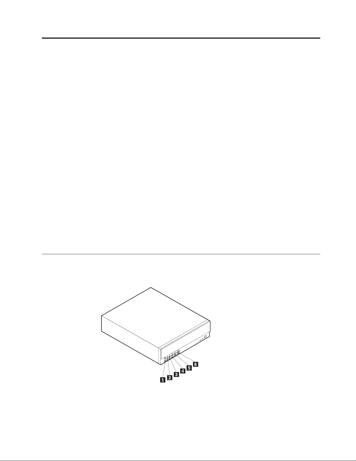
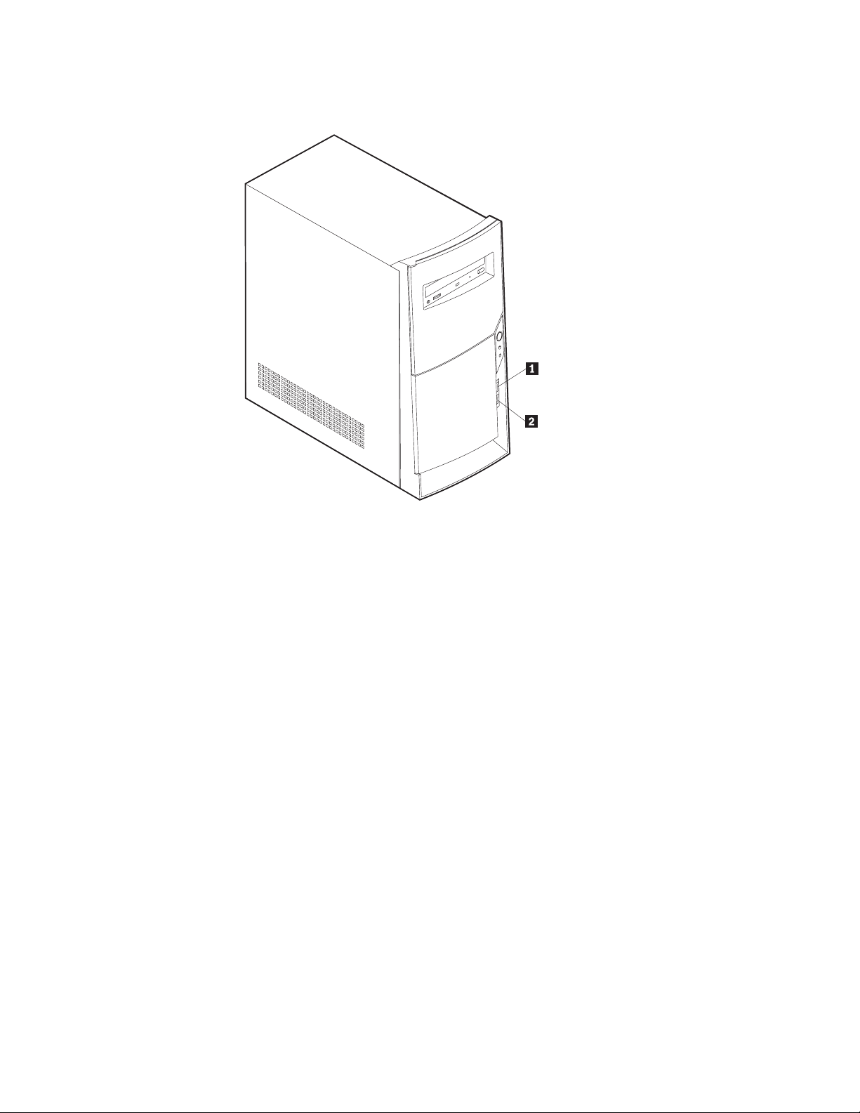
Locating the connectors on the front of your computer
The following illustrations show the location of the connectors on the front of the
small desktop computers.
1
3
9
4
1IEEE 1394 connector (some models) 4S/PDIF connector
2Front USB connector 5Microphone connector
3Front USB connector 6Headphone connector
© Copyright IBM Corp. 2000 19
Page 28
1Front USB connector
2Front USB connector
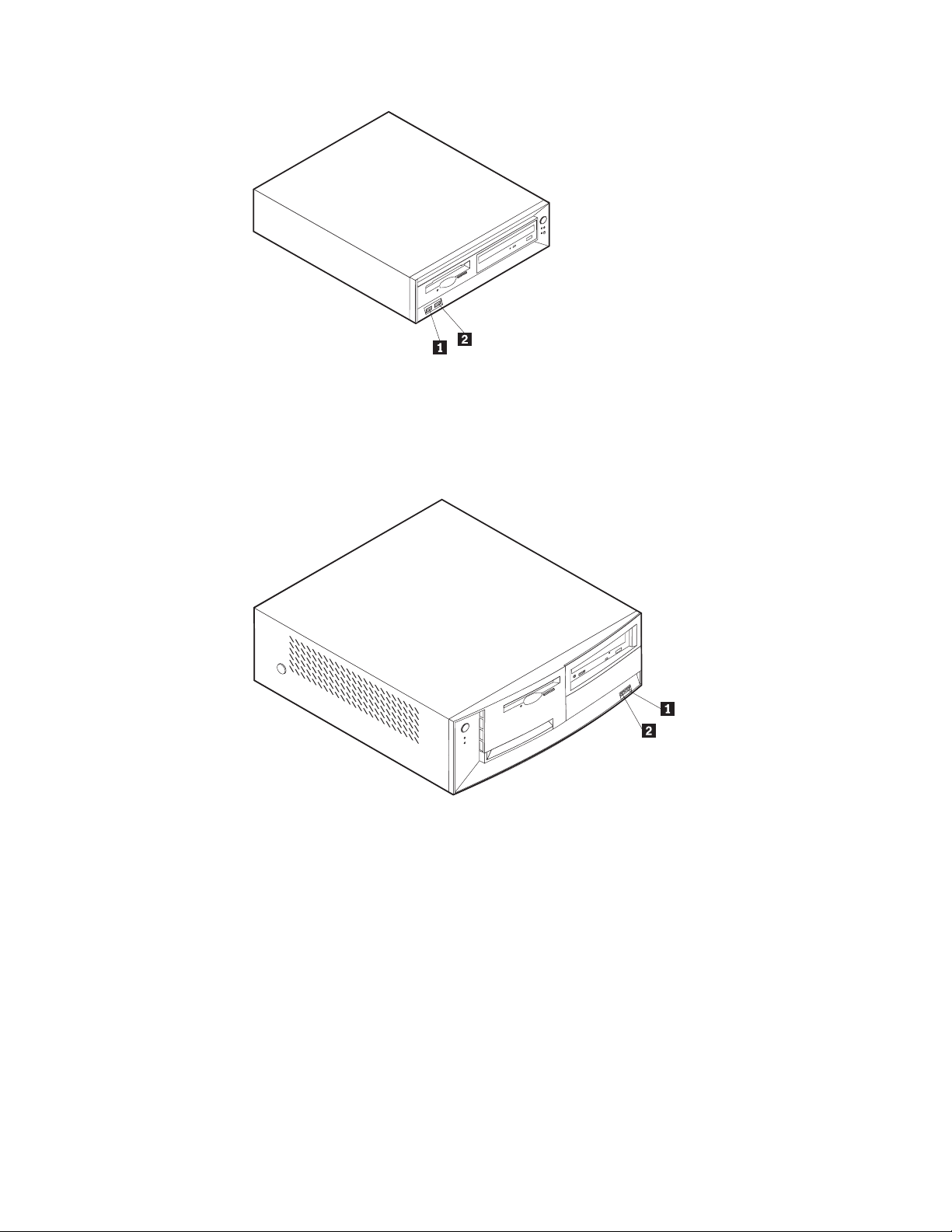
The following illustration shows the location of the connectors on the front of the
desktop computer.
1Front USB connector
2Front USB connector
20 Hardware Maintenance Manual
Page 29
The following illustration shows the location of the connectors on the front of the
microtower computer.
1Front USB connector
2Front USB connector
Chapter 4. Installing Options 21
Page 30
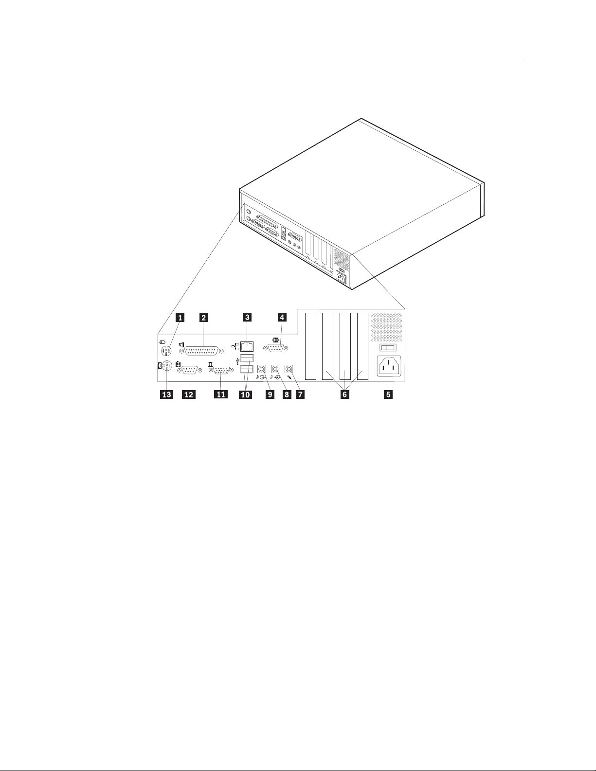
Locating the connectors on the rear of your computer
The following illustration shows the location of the connectors on the rear of the
small desktop model computer.
1Mouse connector 8 Audio line in connector
2Parallel connector 9 Audio line out connector
3Ethernet connector 10USB connectors
4Serial connector 11Monitor connector
5Power connector 12Serial connector
6PCI slots 13Keyboard connector
7Microphone connector
Note: The connectors on the rear of the computer have color-coded icons to help
you to determine where to connect the cables on your computer.
22 Hardware Maintenance Manual
Page 31

The following illustration shows the location of the connectors on the rear of the
desktop model computer.
1Power connector 8Audio line in connector
2Mouse connector 9Audio line out connector
3Parallel connector 10USB connectors
4Ethernet connector 11Monitor connector
5Serial connector 12Serial connector
6PCI slots 13Keyboard connector
7Microphone connector
Note: The connectors on the rear of the computer have color-coded icons to help
you to determine where to connect the cables on your computer.
Chapter 4. Installing Options 23
Page 32

The following illustration shows the location of the connectors on the back of the
microtower model computer.
1Mouse connector 8Audio line out connector
2Keyboard connector 9Audio line in connector
3Serial connector 10Microphone connector
4Parallel connector 11Serial connector
5Monitor connector 12PCI slots
6USB connectors 13Power connector
7Ethernet connector
Note: The connectors on the rear of the computer have color-coded icons to help
you to determine where to connect the cables on your computer.
24 Hardware Maintenance Manual
Page 33

Connector Description
Mouse connector Used to attach a mouse, trackball, or other pointing device that
uses a PS/2 mouse connector.
Keyboard connector Used to attach a keyboard that uses a PS/2 keyboard
connector.
Serial connectors Used to attach an external modem, serial printer, or other device
that uses a 9-pin serial connector.
Parallel connector Used to attach a parallel printer, parallel scanner, or any other
device that requires a 25-pin parallel connection.
USB connectors Used to attach a device that requires a Universal Serial Bus
(USB) connection, such as a USB scanner or USB printer. If you
have more than four USB devices, you can purchase a USB hub,
which you can use to connect additional USB devices.
Ethernet connector Used to attach an Ethernet cable that uses an Ethernet connector.
Note: To operate the computer within FCC Class A or Class B
limits, use a category 5 Ethernet cable.
Audio line out connector Used to send audio signals from the computer to external
devices, such as powered stereo speakers (speakers with built-in
amplifiers), headphones (greater than 18 ohms), multimedia
keyboards, or the audio line in connector on a stereo system or
other external recording device.
Audio line in connector Used to receive audio signals from an external audio device,
such as a stereo system. When you attach an external audio
device, a cable is connected between the audio line out
connector of the device and the audio line in connector of the
computer.
Microphone connector Used to attach a microphone to your computer when you want
to record voice or other sounds on the hard disk using
speech-recognition software.
Home PNA network adapter
Some models might have a Home Phoneline Network Alliance network adapter
with an integrated V.90 modem. In addition to its modem function, this adapter
enables you to use the telephone wiring in your home for peer-to-peer networking.
To use the Home PNA Network adapter, you must install the Intel AnyPoint
software from the Software Selections CD. Each computer on the home PNA
network must have a PNA network adapter and the associated software installed.
For information about using the PNA network adapter or the AnyPoint software,
refer to the AnyPoint documentation (provided with models that come with PNA
network adapters only).
™
Chapter 4. Installing Options 25
Page 34

Connect each computer on a home PNA network directly to a telephone-line wall
connector. If you have more computers than telephone-line wall connectors in a
room, use a telephone splitter at the wall connector.
Actual network transfer speeds depend on many factors, such as home wiring
configuration, and are often less than the maximum possible.
Some Internet service provider (ISP) accounts do not allow Internet sharing or they
charge extra for it. Your ISP access agreement might require you to have more than
one account. Check your ISP access agreement for more information.
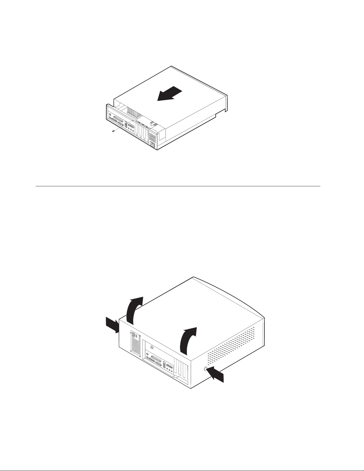
Removing the cover - small desktop model
To remove the cover:
1. Shut down your operating system, remove any media (diskettes, CDs, or tapes)
from the drives, and turn off all attached devices and the computer.
2. Unplug all power cords from electrical outlets.
3. Disconnect all cables attached to the computer. This includes power cords,
input/output (I/O) cables, and any other cables that are connected to the
computer.
4. Remove the screw that secures the top cover at the rear of the system unit.
5. Hold both sides of the system unit top cover and push it forward. Lift the top
cover up to remove it completely.
26 Hardware Maintenance Manual
Page 35
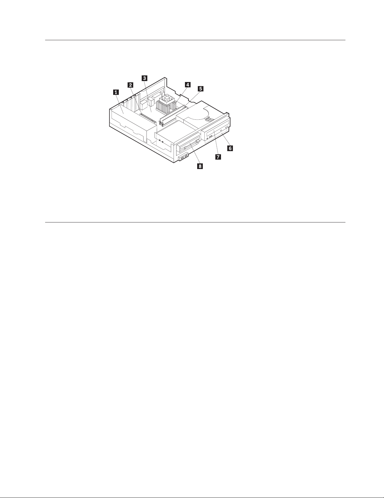
Locating components - small desktop model
The following illustration will help you locate the various components in your
computer.
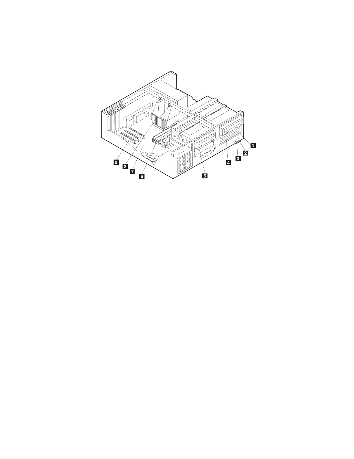
1Power supply 5DIMM
2PCI slot 6Hard disk drive
3System board 7CD drive or DVD drive
4Microprocessor and heat sink 8Diskette drive
Identifying parts on the system board - small desktop model
The system board, also called the planar or motherboard, is the main circuit board in
your computer. It provides basic computer functions and supports a variety of
devices that are IBM-installed or that you can install later.
Chapter 4. Installing Options 27
Page 36

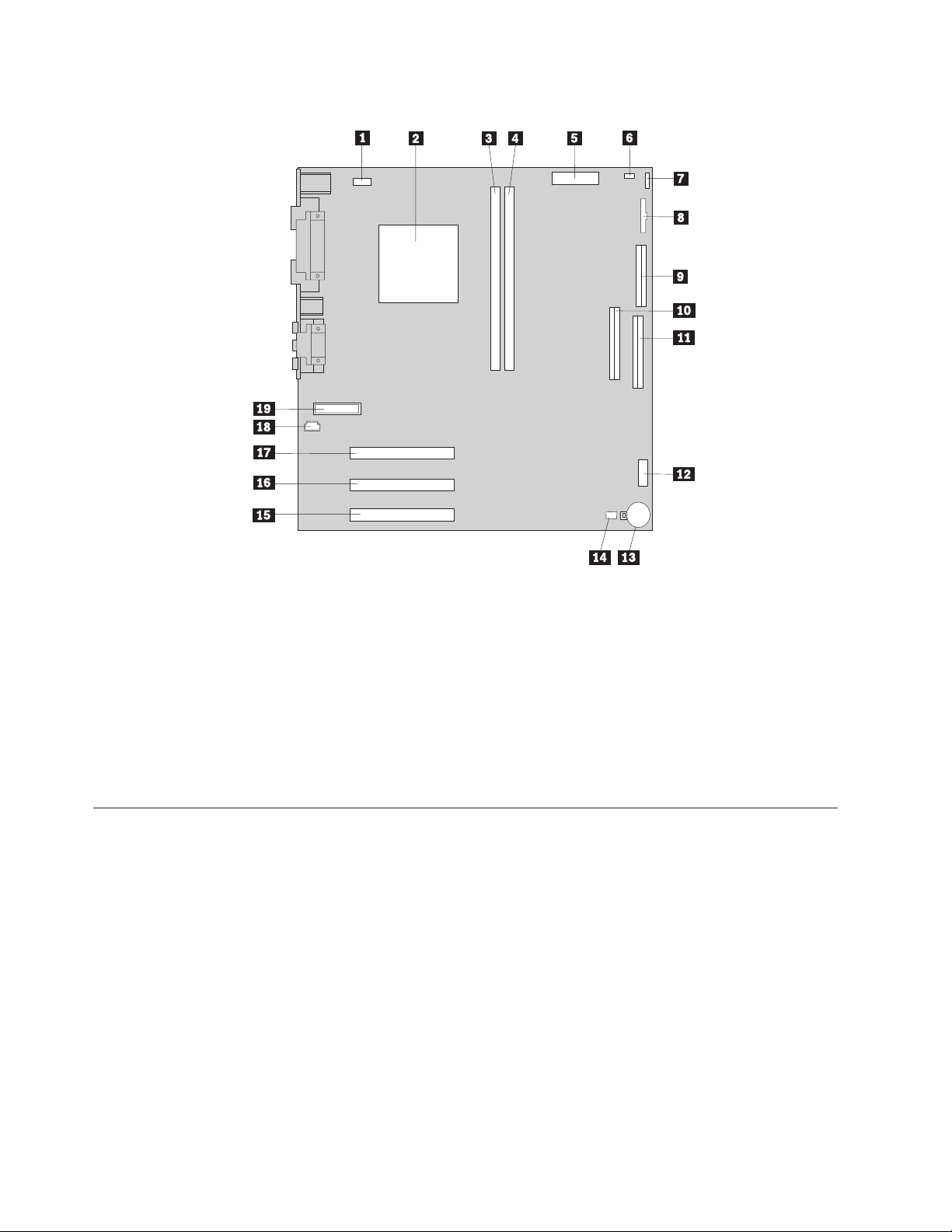
See the following illustration for the location of parts on the system board.
1 Fan connector 11 Primary IDE connector
2 Microprocessor 12 Front USB connector
3 DIMM 1 13 Virtual clear CMOS/BIOS recovery jumper
(JP14)
4 DIMM 2 14 Battery
5 Power connector 15 PCI slot
6 Power connector 16 PCI slot
7 Hard disk LED connector 17 PCI slot
8 Power LED connector 18 CD-ROM audio connector
9 Diskette connector 19 Front panel connector
10Secondary IDE connector
Installing memory - small desktop model
Your computer has two connectors for installing dual in-line memory modules
(DIMMs) that provide up to a maximum of 512 MB of system memory.
Installing DIMMs
When installing DIMMs, the following rules apply:
v Fill each system memory connector sequentially, starting at DIMM 1
v Use 3.3 V, synchronous, 168-pin, unbuffered, 133 MHz, nonparity, synchronous
dynamic random access memory (SDRAM)
v Use 32 MB, 64 MB, 128 MB, or 256 MB DIMMs in any combination
v DIMM heights of 38.1 mm (1.5 inches)
To install a DIMM:
28 Hardware Maintenance Manual
Page 37

1. Remove the cover. See “Removing the cover - small desktop model” on
page 26.
2. To locate the DIMM connectors. See “Identifying parts on the system board -
small desktop model” on page 27.
3. Open the retaining clips.
4. Make sure the notches in the DIMM align with the tabs on the connector. Push
or insert the DIMM straight down into the connector until the retaining clips
close.
Notches
What to do next:
v To work with another option, go to the appropriate section.
v To complete the installation, go to “Replacing the cover and connecting the
cables - small desktop model” on page 33.
Installing adapters - small desktop model
This section provides information and instructions for installing and removing
adapters. Your computer has three expansion slots for low profile peripheral
component interconnect (PCI) adapters.
To install an adapter:
1. Remove the cover. See “Removing the cover - small desktop model” on
page 26.
Chapter 4. Installing Options 29
Page 38

2. Remove the slot screw and slot cover for the appropriate expansion slot.
3. Install the adapter and insert the retaining screw.
What to do next:
v To work with another option, go to the appropriate section.
v To complete the installation, go to “Replacing the cover and connecting the
cables - small desktop model” on page 33.
Installing internal drives - small desktop model
This section provides information and instructions for installing and removing
internal drives.
Internal drives are devices that your computer uses to read and store data. You can
add or replace drives in your computer to increase storage capacity and to enable
your computer to read other types of media such as CD-ROM.
Internal drives are installed in bays. Within this book, the bays are referred to as
bay 1, bay 2, and so on.
When you install an internal drive, it is important to note what type and size of
drive that you can install in each bay. Also, it is important to correctly connect the
internal drive cables to the installed drive.
Drive specifications
Your computer might come with the following IBM-installed drives:
v A 3.5-inch diskette drive in bay 1
v A CD drive or DVD drive in bay 2
v A 3.5-inch hard disk drive in bay 3
Bays that do not have drives installed have a static shield and bay panel installed.
30 Hardware Maintenance Manual
Page 39

The following illustration shows the locations of the drive bays
The following table describes some of the drives that you can install in each bay
and their height requirements.
1Bay 1 - Max Height: 25.4 mm (1.0 in.) 3.5-inch diskette drive (preinstalled in some
models)
2Bay 2 - Max Height: 41.3 mm (1.6 in.) CD-ROM drive (standard in some models)
3Bay 3 - Max Height: 12.7 mm (0.5 in.) 3.5-inch hard disk drive (preinstalled)
Notes:
1. Drives that are greater than 41.3 mm (1.6 in.) high cannot be installed.
2. Install removable media (tape or CD) drives in the accessible bay: bay 1 or 2.
Installing a drive
To install a CD drive or DVD drive in bay 2, follow these steps.
1. Remove the cover (see “Removing the cover - small desktop model” on
page 26).
2. If you are installing a drive with removable media, insert a flat–blade
screwdriver into one of the slots on the static shield in the drive bay into
which you installed the drive and gently pry the static shield loose from the
drive bay.
3. Make sure the drive is set correctly as the master device. Refer to the
documentation that comes with your CD drive or DVD drive for master/slave
jumper information.
4. Lift the latch and remove the drive mounting tray.
5. Install the drive into the bay. Align the screw holes and insert the four screws.
Chapter 4. Installing Options 31
Page 40

6. Slide the drive cage halfway into the mounting tray.
7. Each integrated drive electronics (IDE) drive requires two cables; a four-wire
power cable that connects to the power supply, and a signal cable that
connects to the system board. You might also have an audio cable to connect.
To connect a CD drive or DVD drive to your computer, follow these steps.
a. Locate the signal cable that came with your computer or with the new
drive.
b. Locate the secondary IDE connector and the CD-ROM audio connector on
the system board. See “Identifying parts on the system board - small
desktop model” on page 27.
c. Connect one end of the signal cable to the secondary IDE connector on the
system board and the other to the CD drive or DVD drive.
d. Your computer has extra power connectors for connecting additional
drives. Connect the power cable to the drive.
8. If you have a CD-ROM drive audio cable, connect it to the drive and the
system board.
9. Slide the drive cage in and engage the latch.
10. If the drive you installed is a removable-media drive, remove the bay panel
from the front bezel.
What to do next:
v To work with another option, go to the appropriate section.
v To complete the installation, go to “Replacing the cover and connecting the
cables - small desktop model” on page 33.
32 Hardware Maintenance Manual
Page 41

Installing a Rope Clip - small desktop model
To help prevent hardware theft, you can add a 3/16 inch or 5 mm Rope Clip and
cable to your computer. After you add the security cable, make sure that it does
not interfere with other cables that are connected to the computer.
To install a Rope Clip:
1. Remove the cover (see “Removing the cover - small desktop model” on
page 26).
2. Use a tool, such as a screwdriver, to remove the two metal knockouts.
3. Insert the Rope Clip through the rear panel; then attach and tighten the nuts
with an appropriately sized or adjustable wrench.
4. Replace the computer cover. For more information, see “Replacing the cover
and connecting the cables - small desktop model” on page 33.
5. Thread the cable through the Rope Clip and around an object that is not a part
of or permanently secured to the building structure or foundation, and from
which it cannot be removed; then fasten the cable ends together with a lock.
1 Rope Clip
2 Bolt holes
3 Nuts
What to do next:
To work with another option, go to the appropriate section.
Replacing the cover and connecting the cables - small desktop model
After working with options, you need to install any removed parts, replace the
cover, and reconnect cables, including power cords and telephone lines. Also,
depending on the option that is installed, you might need to confirm the updated
information in the Configuration/Setup Utility program.
To replace the cover and connect cables to your computer:
1. Ensure that all components have been reassembled correctly and that no tools
or loose screws are left inside your computer.
Chapter 4. Installing Options 33
Page 42
2. Clear any cables that might impede the replacement of the cover.
3. Place the cover over the computer and slide it to the rear until it is fully closed.
Secure the cover with the screw.
4. Reconnect the external cables and cords to the computer.
5. To update the configuration, see “Module test menu/hardware configuration
report” on page 13.
Removing the cover - desktop model
To remove the cover:
1. Shut down your operating system, remove any media (diskettes, CDs, or tapes)
from the drives, and turn off all attached devices and the computer.
2. Unplug all power cords from electrical outlets.
3. Disconnect all cables attached to the computer. This includes power cords,
input/output (I/O) cables, and any other cables that are connected to the
computer.
4. Press the buttons on the sides of the computer and pivot the rear end of the
cover up toward the front of the computer.
34 Hardware Maintenance Manual
Page 43
Locating components - desktop model
The following illustration will help you locate the various components in your
computer.
1CD drive or DVD drive 6 DIMMs
2USB connector 7System Board
3USB connector 8 Microprocessor and heat sink
4Hard disk drive 9PCI slots
5Diskette drive
Identifying parts on the system board - desktop model
The system board, also called the planar or motherboard, is the main circuit board in
your computer. It provides basic computer functions and supports a variety of
devices that are IBM-installed or that you can install later.
Chapter 4. Installing Options 35
Page 44
See the following illustration for the location of parts on the system board.
1 Fan connector 11 Primary IDE connector
2 Microprocessor 12 Front USB connector
3 DIMM 1 13 Virtual clear CMOS/BIOS recovery jumper
4 DIMM 2 14 Battery
5 Power connector 15 PCI slot
6 Power connector 16 PCI slot
7 Hard disk LED connector 17 PCI slot
8 Power LED connector 18 CD-ROM audio connector
9 Diskette connector 19 Front panel connector
10Secondary IDE connector
Installing memory - desktop model
Your computer has two connectors for installing dual in-line memory modules
(DIMMs) that provide up to a maximum of 512 MB of system memory.
Installing DIMMs
When installing DIMMs, the following rules apply:
v Fill each system memory connector sequentially, starting at DIMM 1
v Use 3.3 V, synchronous, 168-pin, unbuffered, 133 MHz nonparity synchronous
dynamic random access memory (SDRAM)
v Use 32 MB, 64 MB, 128 MB, or 256 MB DIMMs in any combination
v DIMM heights of 38.1 mm (1.5 inches)
To install a DIMM:
1. Remove the cover. See “Removing the cover - desktop model” on page 34.
36 Hardware Maintenance Manual
Page 45

2. To locate the DIMM connectors. See “Identifying parts on the system board -
desktop model” on page 35.
3. Open the retaining clips.
4. Make sure the notches in the DIMM align with the tabs on the connector. Push
or insert the DIMM straight down into the connector until the retaining clips
close.
Notches
What to do next:
v To work with another option, go to the appropriate section.
v To complete the installation, go to “Replacing the cover and connecting the
cables - desktop model” on page 43.
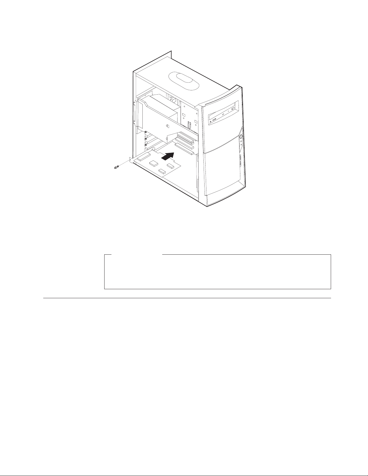
Installing adapters - desktop model
This section provides information and instructions for installing and removing
adapters. Your computer has three expansion slots for peripheral component
interconnect (PCI) adapters. You can install an adapter up to 330 mm (13 inches)
long.
To install an adapter:
1. Remove the cover. See “Removing the cover - desktop model” on page 34.
Chapter 4. Installing Options 37
Page 46

2. Remove the adapter slot cover latch and the slot cover for the appropriate
expansion slot.
3. Remove the adapter from its static-protective package.
4. Install the adapter into the appropriate slot on the system board.
5. Install the adapter slot cover latch.
What to do next:
v To work with another option, go to the appropriate section.
v To complete the installation, go to “Replacing the cover and connecting the
cables - desktop model” on page 43.
Installing internal drives - desktop model
This section provides information and instructions for installing and removing
internal drives.
38 Hardware Maintenance Manual
Page 47

Internal drives are devices that your computer uses to read and store data. You can
add drives to your computer to increase storage capacity and to enable your
computer to read other types of media. Some of the different drives that are
available for your computer are:
v Hard disk drives
v Tape drives
v CD drives or DVD drives
v Removable media drives
Internal drives are installed in bays. Within this book, the bays are referred to as
bay 1, bay 2, and so on.
When you install an internal drive, it is important to note what type and size of
drive that you can install in each bay. Also, it is important to correctly connect the
internal drive cables to the installed drive.
Drive specifications
Your computer comes with the following IBM-installed drives:
v A CD-ROM drive in bay 1 (some models)
v A 3.5-inch hard disk drive in bay 3
v A 3.5-inch diskette drive in bay 4
Models that do not have drives installed in bays 1 and 2 have a static shield and
bay panel installed.
The following illustration shows the locations of the drive bays.
The following table describes some of the drives that you can install in each bay
and their height requirements.
1 Bay 1 - Max Height: 41.3 mm (1.6 in.) CD-ROM drive (standard in some models)
5.25-inch hard disk drive
2 Bay 2 - Max Height: 41.3 mm (1.6 in.) 5.25-inch hard disk drive
3.5-inch hard disk drive (requires a mounting
bracket)
3 Bay 3 - Max Height: 25.4 mm (1.0 in.) 3.5-inch hard disk drive (preinstalled)
Chapter 4. Installing Options 39
Page 48

Notes:
1. Drives that are greater than 41.3 mm (1.6 in.) high cannot be installed.
2. Install removable media (tape or CD) drives in the accessible bay: bay 1 or 2.
Installing a drive
To install an internal drive, follow these steps.
1. Remove the cover. See “Removing the cover - desktop model” on page 34.
2. If your computer has a CD drive or DVD drive, you might need to remove the
signal and power cables from the drive.
3. If the drive you installed is a removable-media drive, remove the bay panel
from the front bezel.
4. Remove the metal shield from the drive bay by inserting a flat–blade
screwdriver into one of the slots and gently pry it loose.
5. Pivot the drive bay latch handle toward the front of the computer and pivot the
drive bay cage toward the front of the computer until the drive cage latch
catches to the chassis.
40 Hardware Maintenance Manual
Page 49

6. Make sure the drive that you are installing is set correctly as either a master or
a slave device.
v If it is the first CD drive or DVD drive, set as a master device.
v If it is an additional CD drive or DVD drive, set as a slave device.
v If it is a hard disk drive, set as a slave device.
Refer to the documentation that comes with your drive for master/slave
jumper information.
7. Install the drive into the bay. Align the screw holes and insert the two screws.
8. Pivot the drive bay cage back into place.
9. Each integrated drive electronics (IDE) drive requires two cables; a four-wire
power cable that connects to the power supply and a signal cable that connects
to the system board. You might also have an audio cable to connect.
The steps to connect an IDE drive are different depending on the type of drive you
are connecting. Locate the procedure below for your drive connection.
To connect the first IDE CD drive or DVD drive
1. Locate the three-connector signal cable that came with your computer or with
the new drive.
Chapter 4. Installing Options 41
Page 50

2. Locate the secondary IDE connector and CD-ROM audio connector on the
system board. See “Identifying parts on the system board - desktop model” on
page 35.
3. Connect one end of the signal cable to the drive and the other to the secondary
IDE connector on the system board. To reduce electronic noise, use the
connectors at the end of the cable only.
4. Your computer has extra power connectors for additional drives. Connect a
power connector to the drive.
5. If you have a CD-ROM drive audio cable, connect it to the drive and the
system board.
To connect an additional IDE CD drive or DVD drive
1. Locate the secondary IDE connector on the system board and the
three-connector signal cable. See “Identifying parts on the system board desktop model” on page 35.
2. Connect the extra connector in the signal cable to the new CD drive or DVD
drive.
3. Your computer has extra power connectors for additional drives. Connect a
power connector to the drive.
To connect an additional IDE hard disk drive
1. You will have to obtain a three-connector, ATA-100 compatible signal cable to
connect your new hard disk.
2. Remove the two-connector cable from the hard disk drive.
3. Locate the primary IDE connector on the system board. One end of the
three-connector cable connects to the hard disk drive and the other connects to
the system board. See “Identifying parts on the system board - desktop model”
on page 35.
4. Connect the extra connector in the signal cable to the new hard disk drive.
5. Your computer has extra power connectors for additional drives. Connect a
power connector to the drive.
What to do next
v To work with another option, go to the appropriate section.
v To complete the installation, go to “Replacing the cover and connecting the
cables - desktop model” on page 43.
Installing a Rope Clip - desktop model
To help prevent hardware theft, you can add a 3/16 inch or 5 mm Rope Clip and
cable to your computer. After you add the security cable, make sure that it does
not interfere with other cables that are connected to the computer.
To install a Rope Clip:
1. Remove the cover. See “Removing the cover - desktop model” on page 34.
2. Use a tool, such as a screwdriver, to remove the two metal knockouts.
3. Insert the Rope Clip through the rear panel; then attach and tighten the nuts
with an appropriately sized or adjustable wrench.
4. Replace the computer cover. For more information, see “Replacing the cover
and connecting the cables - desktop model” on page 43.
42 Hardware Maintenance Manual
Page 51

5. Thread the cable through the Rope Clip and around an object that is not a part
of or permanently secured to the building structure or foundation, and from
which it cannot be removed; then fasten the cable ends together with a lock.
What to do next:
To work with another option, go to the appropriate section.
Replacing the cover and connecting the cables - desktop model
After working with options, you need to install any removed parts, replace the
cover, and reconnect any cables, including power cords and telephone lines. Also,
depending on the option that is installed, you might need to confirm the updated
information in the Configuration/Setup Utility program.
To replace the cover and connect cables to your computer:
1. Ensure that all components have been reassembled correctly and that no tools
or loose screws are left inside your computer.
2. Clear any cables that might impede the replacement of the cover.
Chapter 4. Installing Options 43
Page 52

3. Position the cover over the chassis and pivot the cover down over the
computer until the cover snaps into place.
4. Reconnect the external cables and cords to the computer.
5. To update the configuration, see “Module test menu/hardware configuration
report” on page 13.
Removing the cover - microtower model
To remove the cover:
1. Shut down your operating system, remove any media (diskettes, CDs, or tapes)
from the drives, and turn off all attached devices and the computer.
2. Unplug all power cords from electrical outlets.
3. Disconnect all cables attached to the computer. This includes power cords,
input/output (I/O) cables, and any other cables that are connected to the
computer.
44 Hardware Maintenance Manual
Page 53

4. Remove the thumbscrews from the rear of the computer and slide the cover
toward the rear of the computer.
Chapter 4. Installing Options 45
Page 54

Locating components - microtower model
The following illustration will help you locate the various components in your
computer.
1Microprocessor and heat sink 3PCI adapter
2DIMM 4Power supply
Moving the power supply - microtower model
To perform some operations inside the computer, you might need to move the
power supply to access parts of the system board that are difficult to see or hard to
reach. Use the following procedure to provide easier access to the system board.
DANGER
Do not detach the power supply bracket from the power supply or remove
any of the power supply screws.
1. Remove the thumbscrew securing the power supply to the rear of the chassis.
46 Hardware Maintenance Manual
Page 55

2. Push the metal tab and slide the power supply unit upward.
3. Rotate the power supply outward as shown.
Chapter 4. Installing Options 47
Page 56

4. Remove the power supply and carefully lay it to the side.
5. To replace the power supply, reverse these steps.
Identifying parts on the system board - microtower model
The system board, also called the planar or motherboard, is the main circuit board in
your computer. It provides basic computer functions and supports a variety of
devices that are IBM-installed or that you can install later.
48 Hardware Maintenance Manual
Page 57

See the following illustration for the location of parts on the system board.
1 Fan connector 11 Primary IDE connector
2 Microprocessor 12 Front USB connector
3 DIMM 1 13 Virtual clear CMOS/BIOS recovery jumper
4 DIMM 2 14 Battery
5 Power connector 15 PCI slot
6 Power connector 16 PCI slot
7 Hard disk LED connector 17 PCI slot
8 Power LED connector 18 CD-ROM audio connector
9 Diskette connector 19 Front panel connector
10Secondary IDE connector
Installing memory - microtower model
Your computer has two connectors for installing dual in-line memory modules
(DIMMs) that provide up to a maximum of 512 MB of system memory.
Installing DIMMs
When installing DIMMs, the following rules apply:
v Fill each system memory connector sequentially, starting at DIMM 1
v Use 3.3 V, synchronous, 168-pin, unbuffered, 133 MHz nonparity synchronous
dynamic random access memory (SDRAM)
v Use 32 MB, 64 MB, 128 MB, or 256 MB DIMMs in any combination
v DIMM heights of 38.1 mm (1.5 inches)
To install a DIMM:
1. Remove the cover. See “Removing the cover - microtower model” on page 44.
Chapter 4. Installing Options 49
Page 58

2. You might have to remove an adapter to gain access to the DIMM slots. See
“Installing adapters - microtower model”.
3. To locate the DIMM connectors. See “Identifying parts on the system board -
microtower model” on page 48.
4. Open the retaining clips.
5. Make sure the notches in the DIMM align with the tabs on the connector. Push
or insert the DIMM straight down into the connector until the retaining clips
close.
Notches
What to do next:
v Replace any adapters that were removed.
v Replace the power supply.
v To work with another option, go to the appropriate section.
v To complete the installation, go to “Replacing the cover and connecting the
cables - microtower model” on page 56.
Installing adapters - microtower model
This section provides information and instructions for installing and removing
adapters. Your computer has three expansion slots for peripheral component
interconnect (PCI) adapters. You can install an adapter up to 330 mm (13 inches)
long.
To install an adapter:
1. Remove the cover. See “Removing the cover - microtower model” on page 44.
50 Hardware Maintenance Manual
Page 59
2. Remove the adapter slot cover for the appropriate expansion slot.
3. Remove the adapter from its static-protective package.
4. Install the adapter into the appropriate slot on the system board.
5. Install the screws that secure the adapter.
What to do next
v To work with another option, go to the appropriate section.
v To complete the installation, go to “Replacing the cover and connecting the
cables - microtower model” on page 56.
Installing internal drives - microtower model
This section provides information and instructions for installing and removing
internal drives.
Internal drives are devices that your computer uses to read and store data. You can
add drives to your computer to increase storage capacity and to enable your
computer to read other types of media. Some of the different drives that are
available for your computer are:
v Hard disk drives
v Tape drives
v CD drives or DVD drives
v Removable media drives
Internal drives are installed in bays. Within this book, the bays are referred to as
bay 1, bay 2, and so on.
Chapter 4. Installing Options 51
Page 60

When you install an internal drive, it is important to note what type and size of
drive that you can install in each bay. Also, it is important to correctly connect the
internal drive cables to the installed drive.
Drive specifications
Your computer comes with the following IBM-installed drives:
v A CD drive or DVD drive in bay 1 (some models)
v A 3.5-inch diskette disk drive in bay 3
v A 3.5-inch hard drive in bay 4
Models that do not have drives installed in bays 1 and 2 have a static shield and
bay panel installed.
The following illustration shows the locations of the drive bays.
The following table describes some of the drives you can install in each bay and
their height requirements.
1Bay 1 - Maximum Height: 41.3 mm (1.6 in.) CD-ROM drive (standard in some models)
2Bay 2 - Maximum Height: 41.3 mm (1.6 in.) 5.25-inch hard disk drive
3Bay 3 - Maximum Height: 25.4 mm (1.0 in.) 3.5-inch diskette drive (preinstalled)
4Bay 4 - Maximum Height: 25.4 mm (1.0 in.) Hard disk drive (preinstalled)
Notes:
1. Drives that are greater than 41.3 mm (1.6 in.) high cannot be installed.
2. Install removable media (tape or CD) drives in the accessible bays: bay 1 or 2.
52 Hardware Maintenance Manual
5.25-inch hard disk drive
3.5-inch hard disk drive (requires a
mounting bracket)
CD-ROM drive
DVD-ROM drive
Page 61

Installing a drive
To install an internal drive, follow these steps.
1. Remove the cover. See “Removing the cover - microtower model” on page 44.
Note: If your computer has a CD drive or DVD drive, you might need to
remove the signal and power cables from the drive.
2. Remove the bay panel from the drive bay by inserting a flat-blade screwdriver
at the end and gently prying it loose.
3. Remove the metal shield from the drive bay by inserting a flat-blade
screwdriver into one of the slots and gently prying it loose.
4. Make sure the drive that you are installing is set correctly as either a master or
a slave device.
v If it is the first CD drive or DVD drive, set as a master device.
v If it is an additional CD drive or DVD drive, set as a slave device.
v If it is a hard disk drive, set as a slave device.
Refer to the documentation that comes with your drive for master/slave
jumper information.
Chapter 4. Installing Options 53
Page 62

5. Install the drive into the bay. Align the screw holes, and insert the two screws.
6. Each integrated drive electronics (IDE) drive requires two cables; a four-wire
power cable that connects to the power supply and a signal cable that connects
to the system board. You might also have an audio cable to connect.
The steps to connect an IDE drive are different depending on the type of drive you
are connecting. Locate the procedure below for your drive connection.
To connect the first IDE CD drive or DVD drive
1. Locate the three-connector signal cable that came with your computer or with
the new drive.
2. Locate the secondary IDE connector on the system board. See “Identifying parts
on the system board - microtower model” on page 48.
3. Connect one end of the signal cable to the drive and the other to the secondary
IDE connector on the system board. To reduce electronic noise, use the
connectors at the end of the cable only.
4. Your computer has extra power connectors for additional drives. Connect a
power connector to the drive.
54 Hardware Maintenance Manual
Page 63

5. If you have a CD-ROM drive audio cable, connect it to the drive and the
system board.
To connect an additional IDE CD drive or DVD drive
1. Locate the secondary IDE connector on the system board and the
three-connector signal cable. See “Identifying parts on the system board microtower model” on page 48.
2. Connect the extra connector in the signal cable to the new CD drive or DVD
drive.
3. Your computer has extra power connectors for additional drives. Connect a
power connector to the drive.
To connect an additional IDE hard disk drive
1. You will have to obtain a three-connector, ATA-100 compatible signal cable to
connect your new hard disk.
2. Remove the two-connector cable from the hard disk drive.
3. Locate the primary IDE connector on the system board. One end of the
three-connector cable connects to the hard disk drive and the other connects to
the system board. See “Identifying parts on the system board - microtower
model” on page 48.
4. Connect the extra connector in the signal cable to the new hard disk drive.
5. Your computer has extra power connectors for additional drives. Connect a
power connector to the drive.
What to do next
v To work with another option, go to the appropriate section.
v To complete the installation, go to “Replacing the cover and connecting the
cables - microtower model” on page 56.
Installing a Rope Clip - microtower model
To help prevent hardware theft, you can add a 3/16 inch or 5 mm Rope Clip and
cable to your computer. After you add the security cable, make sure that it does
not interfere with other cables that are connected to the computer.
To install a Rope Clip:
1. Remove cover (see “Removing the cover - microtower model” on page 44).
2. Use a tool, such as a screwdriver, to remove the two metal knockouts.
3. Insert the Rope Clip through the rear panel; then attach and tighten the nuts
with an appropriately sized or adjustable wrench.
4. Replace the computer cover. For more information, see “Replacing the cover
and connecting the cables - microtower model” on page 56.
5. Thread the cable through the Rope Clip and around an object that is not a part
of or permanently secured to the building structure or foundation, and from
Chapter 4. Installing Options 55
Page 64

which it cannot be removed; then fasten the cable ends together with a lock.
1Rope Clip
2Bolt holes
3Nuts
What to do next:
To work with another option, go to the appropriate section.
Replacing the cover and connecting the cables - microtower model
After working with options, you need to install any removed parts, replace the
cover, and reconnect any cables, including power cords and telephone lines. Also,
depending on the option that is installed, you might need to confirm the updated
information in the Configuration/Setup Utility program.
To replace the cover and connect cables to your computer:
1. Ensure that all components have been reassembled correctly and that no tools
or loose screws are left inside your computer.
2. Clear any cables that might impede the replacement of the cover.
56 Hardware Maintenance Manual
Page 65

3. Position the cover over the chassis so that the front edge is approximately one
inch away from the front bezel.
4. Lower the cover down over the chassis so that the rail guides engage the rails.
5. Slide the cover forward. You might need to lift the front of the cover slightly to
align it properly.
6. Insert the three thumbscrews into the holes in the cover and the chassis and
tighten.
7. Reconnect the external cables and cords to the computer.
8. To update the configuration, see “Module test menu/hardware configuration
report” on page 13.
Important:
When the power cord is first plugged in, the computer might appear to
power on for a few seconds, then power off. This is a normal sequence to
enable the computer to initialize.
Chapter 4. Installing Options 57
Page 66

58 Hardware Maintenance Manual
Page 67

Chapter 5. FRU Replacements
Identifying parts on the system board .....59
Replacing a System Board - Small Desktop Model 60
Replacing a processor - Small Desktop Model . . . 61
Power supply removal - Small Desktop Model . . 62
Replacing a System Board - Desktop Model . . . 62
Identifying parts on the system board
Replacingaprocessor-DesktopModel.....63
Power supply removal - Desktop Model .....64
Replacing a system board - Microtower Model . . 65
Replacingaprocessor-MicrotowerModel....66
Power supply removal - Microtower Model . . . 66
© Copyright IBM Corp. 2000 59
Page 68

See the following illustration for the location of parts on the system board.
1 Fan connector 11 Primary IDE connector
2 Microprocessor 12 Front USB connector
3 DIMM 1 13 Virtual clear CMOS/BIOS recovery jumper
4 DIMM 2 14 Battery
5 Power connector 15 PCI slot
6 Power connector 16 PCI slot
7 Hard disk LED connector 17 PCI slot
8 Power LED connector 18 CD-ROM audio connector
9 Diskette connector 19 Front panel connector
10Secondary IDE connector
Replacing a System Board - Small Desktop Model
Important:
Before replacing a system board, back up Asset information by using the “Asset EEPROM
backup” on page 16.
60 Hardware Maintenance Manual
Page 69

Notes:
1. The BIOS and Vital Product Data (VPD) for the computer you are servicing must be
installed on the new system board (FRU) after it is installed in the computer. To do
this, you must run the Flash Update program using the Flash Update diskette. See
“BIOS levels” on page 199, “Vital product data” on page 198, and “Flash (BIOS/VPD)
update procedure” on page 200.
2. Always ensure the latest level of BIOS is installed on the computer. A down level BIOS
may cause false errors and unnecessary replacement of the system board.
3. The processor is a separate FRU from the system board and is not included with the
system board FRU.
4. If the new system board does not correct the problem, reinstall the options on the old
system board, reinstall the old system board, then replace the processor.
1. Remove the cover. See “Removing the cover - small desktop model” on
page 26.
2. Remove the 4 screws that attach the system board to the chassis. **This graphic
is incorrect. Correct graphic is in process.**
3. Remove the board from the chassis.
4. Remove the processor from the old system board and install it on the new
system board.
5. Remove any of the following installed options on the old system board, and
install them on the new system board.
v Memory modules
6. Ensure that the new system board jumper settings match the old system board
jumper settings.
Replacing a processor - Small Desktop Model
Attention: When you handle ESD-sensitive devices, take precautions to avoid
damage from static electricity. For details on handling these devices, see “Handling
electrostatic discharge-sensitive devices” on page 210.
1. Review the safety precautions listed in “Safety information” on page 207.
Chapter 5. FRU Replacements 61
Page 70

2. Turn off the system and peripheral devices and disconnect all external cables
and power cords; then, remove the cover (see “Removing the cover - small
desktop model” on page 26 for details).
3. Push down on the retainer clip, and at the same time, use a flat bladed
screwdriver to carefully pry the metal loop from under the hook attaching the
fansink to the processor.
4. Carefully remove the other metal loop from the hook attaching the fansink to
the processor. Lift up and remove the fansink.
Note: Once you remove the heat sink from the microprocessor, you must
replace it with a new device.
5. Pull out and lift up the release lever and remove the microprocessor from the
connector. Store the microprocessor in a static-protective bag for possible future
use.
Power supply removal - Small Desktop Model
1. Remove the cover. See “Removing the cover - small desktop model” on
page 26.
2. Remove the four screws that hold the power supply to the back of the chassis.
3. The power supply is attached to the base of the chassis by a latch on the front.
Slide the power supply forward to dislatch if from the chassis.
4. Lift out the power supply.
Replacing a System Board - Desktop Model
Important:
Before replacing a system board, back up Asset information by using the “Asset EEPROM
backup” on page 16.
62 Hardware Maintenance Manual
Page 71

Notes:
1. The BIOS and Vital Product Data (VPD) for the computer you are servicing must be
installed on the new system board (FRU) after it is installed in the computer. To do
this, you must run the Flash Update program using the Flash Update diskette. See
“BIOS levels” on page 199, “Vital product data” on page 198, and “Flash (BIOS/VPD)
update procedure” on page 200.
2. Always ensure the latest level of BIOS is installed on the computer. A down level BIOS
may cause false errors and unnecessary replacement of the system board.
3. The processor is a separate FRU from the system board and is not included with the
system board FRU.
4. If the new system board does not correct the problem, reinstall the options on the old
system board, reinstall the old system board, then replace the processor.
1. Remove the cover. See “Removing the cover - desktop model” on page 34.
2. Remove the 7 screws that attach the system board to the chassis.
3. Remove the board from the chassis.
4. Remove the processor from the old system board and install it on the new
system board.
5. Remove any of the following installed options on the old system board, and
install them on the new system board.
v Memory modules
6. Ensure that the new system board jumper settings match the old system board
jumper settings.
Replacing a processor - Desktop Model
Attention: When you handle ESD-sensitive devices, take precautions to avoid
damage from static electricity. For details on handling these devices, see “Handling
electrostatic discharge-sensitive devices” on page 210.
1. Review the safety precautions listed in “Safety information” on page 207.
Chapter 5. FRU Replacements 63
Page 72

2. Turn off the system and peripheral devices and disconnect all external cables
and power cords; then, remove the cover (see “Removing the cover - desktop
model” on page 34 for details).
3. Push down on the retainer clip, and at the same time, use a flat bladed
screwdriver to carefully pry the metal loop from under the hook attaching the
fansink to the processor.
4. Carefully remove the other metal loop from the hook attaching the fansink to
the processor. Lift up and remove the fansink.
Note: Once you remove the heat sink from the microprocessor, you must
replace it with a new device.
5. Pull out and lift up the release lever and remove the microprocessor from the
connector. Store the microprocessor in a static-protective bag for possible future
use.
Power supply removal - Desktop Model
1. Remove the cover. See “Removing the cover - desktop model” on page 34.
2. Remove the four screws that hold the power supply to the back of the chassis.
3. The power supply is attached to the base of the chassis by a latch on the front.
Slide the power supply forward to dislatch if from the chassis.
4. Lift out the power supply.
64 Hardware Maintenance Manual
Page 73

Replacing a system board - Microtower Model
Important:
Before replacing a system board, back up Asset information by using the “Asset EEPROM
backup” on page 16.
Notes:
1. The BIOS and Vital Product Data (VPD) for the computer you are servicing must be
installed on the new system board (FRU) after it is installed in the computer. To do
this, you must run the Flash Update program using the Flash Update diskette. See
“BIOS levels” on page 199, “Vital product data” on page 198, and “Flash (BIOS/VPD)
update procedure” on page 200.
2. Always ensure the latest level of BIOS is installed on the computer. A down level BIOS
may cause false errors and unnecessary replacement of the system board.
3. The processor is a separate FRU from the system board and is not included with the
system board FRU.
4. If the new system board does not correct the problem, reinstall the options on the old
system board, reinstall the old system board, then replace the processor.
To replace the system board, do the following:
1. Remove the cover (see “Removing the cover - microtower model” on page 44).
2. Remove the 7 screws that attach the system board to the chassis.
3. Remove the board from the chassis.
4. Remove the processor from the old system board and install it on the new
system board.
5. Remove any of the following installed options on the old system board, and
install them on the new system board.
Chapter 5. FRU Replacements 65
Page 74

v Memory modules
6. Ensure that the new system board jumper settings match the old system board
jumper settings.
Replacing a processor - Microtower Model
Attention: When you handle ESD-sensitive devices, take precautions to avoid
damage from static electricity. For details on handling these devices, see “Handling
electrostatic discharge-sensitive devices” on page 210.
1. Review the safety precautions listed in “Safety information” on page 207.
2. Turn off the system and peripheral devices and disconnect all external cables
and power cords; then, remove the cover (see “Removing the cover microtower model” on page 44 for details).
3. Push down on the retainer clip, and at the same time, use a flat bladed
screwdriver to carefully pry the metal loop from under the hook attaching the
fansink to the processor.
4. Carefully remove the other metal loop from the hook attaching the fansink to
the processor. Lift up and remove the fansink.
Note: Once you remove the heat sink from the microprocessor, you must
replace it with a new device.
5. Pull out and lift up the release lever and remove the microprocessor from the
connector. Store the microprocessor in a static-protective bag for possible future
use.
Power supply removal - Microtower Model
1. Remove the cover (see “Removing the cover - microtower model” on page 44).
2. Remove the screw that secures the power supply to the rear of the chassis.
3. Push the metal tab that secures the power supply to the chassis to release the
power supply.
66 Hardware Maintenance Manual
Page 75

4. Slide the power supply unit up toward the top of the chassis.
5. Rotate the power supply outward as shown.
Chapter 5. FRU Replacements 67
Page 76

6. Pull the power supply forward and carefully rotate it toward the front of the
chassis.
68 Hardware Maintenance Manual
Page 77

Chapter 6. Symptom-to-FRU Index
SDRAM memory errors ..........70
Hard disk drive boot error .........70
Power Supply Errors ...........71
Diagnostic error codes...........72
Beepsymptoms.............90
The Symptom-to-FRU index lists error symptoms and possible causes. The most
likely cause is listed first. Always begin with ″General Checkout″ on page 1. This
index can also be used to help you decide which FRUs to have available when
servicing a computer. If you are unable to correct the problem using this index, go
to “Undetermined problems” on page 109.
Notes:
v If you have both an error message and an incorrect audio response, diagnose the error
message first.
v If you cannot run the diagnostic tests or you get a diagnostic error code when running a
test, but did receive a POST error message, diagnose the POST error message first.
v If you did not receive any error message, look for a description of your error symptoms
in the first part of this index.
v Check the hard disk drive jumper settings before you replace a hard disk drive.
Important:
Some errors are indicated with a series of beep codes (see “Beep symptoms” on page 90).
No-beepsymptoms............92
POST error codes ............93
Miscellaneous error messages ........107
Undetermined problems ..........109
Type 2254, 2256, 2257, 6336, 6337, 6339, 6341, 6342, 6346, 6347, 6348 computers default to
come up quiet (no beep and no memory count and checkpoint code display) when no
errors are detected by POST. To enable beep and memory count and checkpoint code
display when a successful POST occurs, do the following:
1. Select Start Options in the Configuration/Setup Utility program (see “Setup Utility
program” on page 10).
2. Set Power-On Self-Test to Enhanced.
The processor is a separate FRU from the system board; the processor is not included with
the system board FRU.
© Copyright IBM Corp. 2000 69
Page 78

SDRAM memory errors
SDRAM error messages issued by the IBM PC Enhanced Diagnostics.
Error FRU/Action
2xx
A memory error was detected in SDRAM
socket Y.
Corrupt BIOS
Replace the SDRAM in the socket identified
by the last digit of the error code.
Re-run the test.
If the same error code occurs again, replace
the system board.
Reflash the BIOS.
Information in BIOS is not as expected.
Not able to find expected DMI information
from BIOS.
Test aborted by user Restart test.
Note: Y is the SDRAM socket number. Use the System Board Layout section in the
latest Hardware Maintenance Manual (HMM) to reference the memory
sockets.
Hard disk drive boot error
A hard disk drive boot error (error code 17XX) can have the following causes.
Error FRU/Action
The start-up drive is not in the boot
sequence in configuration.
No operating system installed on the boot
drive.
The boot sector on the start-up drive is
corrupted.
The drive is defective. Replace the hard disk drive.
Perform boot block recovery.
Replace the system board.
Check the configuration and ensure the
start-up drive is in the boot sequence.
Install an operating system on the boot
drive.
The drive must be formatted, do the
following:
1. Attempt to access and recover (back-up)
the failing hard disk drive.
2. Using the operating systems programs,
format the hard disk drive.
3. Go to “Preparing the hard disk drive for
use” on page 17.
70 Hardware Maintenance Manual
Page 79

Power Supply Errors
If the power-on indicator is not on, the power supply fan is not running, or the
computer will not power-off, use the following procedures.
Check/Verify FRU/Action
Check the following for proper installation.
v Power Cord
v On/Off Switch connector
v On/Off Switch Power Supply connector
v System Board Power Supply connectors
v Microprocessor(s) connection
Check the power-on switch for continuity. Power Cord
Check the power-on switch for continuity. Power-on Switch
Reseat
Chapter 6. Symptom-to-FRU Index 71
Page 80

Diagnostic error codes
Refer to the following diagnostic error codes when using the diagnostic tests. See
″Diagnostics″ on page 9 for the specific type for information about the Diagnostic
programs.
In the following index, X can represent any number.
Diagnostic Error Code FRU/Action
000-000-XXX
BIOS Test Passed
000-002-XXX
BIOS Timeout
000-024-XXX
BIOS Addressing test failure
000-025-XXX
BIOS Checksum Value error
000-026-XXX
FLASH data error
000-027-XXX
BIOS Configuration/Setup error
000-034-XXX
BIOS Buffer Allocation failure
000-035-XXX
BIOS Reset Condition detected
000-036-XXX
BIOS Register error
000-038-XXX
BIOS Extension failure
000-039-XXX
BIOS DMI data error
000-195-XXX
BIOS Test aborted by user
000-196-XXX
BIOS test halt, error threshold exceeded
1. No action
1. Flash the system
2. System board
1. Flash the system
2. System board
1. Flash the system
2. Boot block
3. System board
1. Flash the system
2. Boot block
3. System board
1. Run Setup
2. Flash the system
3. Boot block
4. System board
1. Reboot the system
2. Flash the system
3. Run memory test
4. System board
1. Flash the system
2. System board
1. Flash the system
2. Boot block
3. System board
1. Flash the system
2. Adapter card
3. System board
1. Flash the system
2. System board
1. Information
2. Re-start the test, if necessary
1. Press F3 to review the log file
2. Re-start the test to reset the log file
72 Hardware Maintenance Manual
Page 81

Diagnostic Error Code FRU/Action
000-197-XXX
BIOS test warning
1. Make sure the component that is called
out is connected and/or enabled
2. Re-run test
3. Component that is called out in warning
statement
4. Component under test
000-198-XXX
BIOS test aborted
1. If a component is called out, make sure
it is connected and/or enabled
2. Flash the system and re-test
3. Go to the ″Undetermined problems″
section
000-199-XXX
BIOS test failed, cause unknown
1. Go to the ″Undetermined problems″
section
2. Flash the system and re-test
3. Replace component under function test
000-250-XXX
BIOS APM failure
000-270-XXX
BIOS ACPI failure
001-000-XXX
System Test Passed
001-00X-XXX
System Error
001-01X-XXX
System Error
001-024-XXX
System Addressing test failure
001-025-XXX
System Checksum Value error
001-026-XXX
System FLASH data error
001-027-XXX
System Configuration/Setup error
1. Flash the system
2. System board
1. Flash the system
2. System board
1. No action
1. System board
1. System board
1. System board
1. Flash the system
2. System board
1. Flash the system
2. System board
1. Run Setup
2. Flash the system
3. System board
001-032-XXX
System Device Controller failure
001-034-XXX
System Device Buffer Allocation failure
1. System board
1. Reboot the system
2. Flash the system
3. Run memory test
4. System board
001-035-XXX
System Device Reset condition detected
001-036-XXX
System Register error
1. System board
1. System board
Chapter 6. Symptom-to-FRU Index 73
Page 82

Diagnostic Error Code FRU/Action
001-038-XXX
System Extension failure
001-039-XXX
System DMI data structure error
001-040-XXX
System IRQ failure
001-041-XXX
System DMA failure
001-195-XXX
System Test aborted by user
001-196-XXX
System test halt, error threshold exceeded
001-197-XXX
System test warning
001-198-XXX
System test aborted
001-199-XXX
System test failed, cause unknown
001-250-XXX
System ECC error
001-254-XXX
001-255-XXX
001-256-XXX
001-257-XXX
System DMA error
001-260-XXX
001-264-XXX
System IRQ error
001-268-XXX
System IRQ1 failure
001-269-XXX
System IRQ2 failure
001-270-XXX
System IRQ3 failure
1. Adapter card
2. System board
1. Flash the system
2. System board
1. Power-off/on system and re-test
2. System board
1. Power-off/on system and re-test
2. System board
1. Information
2. Re-start the test, if necessary
1. Press F3 to review the log file
2. Re-start the test to reset the log file
1. Make sure the component that is called
out is connected and/or enabled
2. Re-run test
3. Component that is called out in warning
statement
4. Component under test
1. If a component is called out, make sure
it is connected and/or enabled
2. Flash the system and re-test
3. Go to the ″Undetermined problems″
section
1. Go to the ″Undetermined problems″
section
2. Flash the system and re-test
3. Replace component under function test
1. System board
1. System board
1. System board
1. Device on IRQ1
2. System board
1. Device on IRQ2
2. System board
1. Device on IRQ3
2. System board
74 Hardware Maintenance Manual
Page 83

Diagnostic Error Code FRU/Action
001-271-XXX
System IRQ4 failure
001-272-XXX
System IRQ5 failure
001-273-XXX
System IRQ6
(diskette drive) failure
1. Device on IRQ4
2. System board
1. Device on IRQ5
2. System board
1. Diskette Cable
2. Diskette drive
3. System board
001-274-XXX
System IRQ7 failure
001-275-XXX
System IRQ8 failure
001-276-XXX
System IRQ9 failure
001-277-XXX
System IRQ10 failure
001-278-XXX
System IRQ11 failure
001-279-XXX
System IRQ12 failure
001-280-XXX
System IRQ13 failure
001-281-XXX
System IRQ14
(hard disk drive) failure
1. Device on IRQ7
2. System board
1. Device on IRQ8
2. System board
1. Device on IRQ9
2. System board
1. Device on IRQ10
2. System board
1. Device on IRQ11
2. System board
1. Device on IRQ12
2. System board
1. Device on IRQ13
2. System board
1. Hard disk drive cable
2. Hard disk drive
3. System board
001-282-XXX
System IRQ15 failure
001-286-XXX
001-287-XXX
1. Device on IRQ15
2. System board
1. System board
001-288-XXX
System Timer failure
001-292-XXX
System CMOS
RAM error
001-293-XXX
System CMOS Battery
001-298-XXX
System RTC date/time update failure
001-299-XXX
System RTC periodic interrupt failure
001-300-XXX
System RTC Alarm failure
1. Run Setup and re-test
2. System board
1. Battery
2. System board
1. Flash the system
2. System board
1. System board
1. System board
Chapter 6. Symptom-to-FRU Index 75
Page 84

Diagnostic Error Code FRU/Action
001-301-XXX
System RTC Century byte error
005-000-XXX
Video Test Passed
005-00X-XXX
Video error
005-010-XXX
005-011-XXX
005-012-XXX
005-013-XXX
Video Signal failure
005-016-XXX
Video Simple Pattern
test failure
005-024-XXX
Video Addressing test failure
005-025-XXX
Video Checksum Value error
005-027-XXX
Video Configuration/Setup error
005-031-XXX
Video Device Cable failure
005-032-XXX
Video Device Controller failure
005-036-XXX
Video Register error
005-038-XXX
System BIOS extension failure
005-040-XXX
Video IRQ failure
005-195-XXX
Video Test aborted by user
005-196-XXX
Video test halt, error threshold exceeded
1. Flash the system
2. System board
1. No action
1. Video card, if installed
2. System board
1. Video card, if installed
2. System board
1. Video Ram
2. Video card, if installed
3. System board
1. Video card, if installed
2. System board
1. Video card, if installed
2. System board
1. Run Setup
2. Video drivers update
3. Video card, if installed
4. System board
1. Video cable
2. Monitor
3. Video card, if installed
4. System board
1. Video card, if installed
2. System board
1. Video card, if installed
2. System board
1. Video card, if installed
2. System board
1. Video card, if installed
2. System board
1. Information
2. Re-start the test, if necessary
1. Press F3 to review the log file
2. Re-start the test to reset the log file
76 Hardware Maintenance Manual
Page 85

Diagnostic Error Code FRU/Action
005-197-XXX
Video test warning
1. Make sure the component that is called
out is connected and/or enabled
2. Re-run test
3. Component that is called out in warning
statement
4. Component under test
005-198-XXX
Video test aborted
1. If a component is called out, make sure
it is connected and/or enabled
2. Flash the system and re-test
3. Go to the ″Undetermined problems″
section
005-199-XXX
Video test failed, cause unknown
1. Go to the ″Undetermined problems″
section
2. Flash the system and re-test
3. Replace component under function test
005-2XX-XXX
005-3XX-XXX
Video subsystem error
006-000-XXX
Diskette interface Test Passed
006-0XX-XXX
Diskette interface error
1. Video card, if installed
2. System board
1. No action
1. Diskette drive Cable
2. Diskette drive
3. System board
006-195-XXX
Diskette interface Test aborted by user
006-196-XXX
Diskette interface test halt, error threshold
exceeded
006-197-XXX
Diskette interface test warning
1. Information
2. Re-start the test, if necessary
1. Press F3 to review the log file
2. Re-start the test to reset the log file
1. If a component is called out, make sure
it is connected and/or enabled
2. Re-run test
3. Component that is called out in warning
statement
4. Component under test
006-198-XXX
Diskette interface test aborted
1. If a component is called out, make sure
it is connected and/or enabled
2. Flash the system and re-test
3. Go to the ″Undetermined problems″
section
006-199-XXX
Diskette interface test failed, cause unknown
1. Go to the ″Undetermined problems″
section
2. Flash the system and re-test
3. Replace component under function test
006-25X-XXX
Diskette interface Error
1. Diskette drive cable
2. Diskette drive
3. System board
Chapter 6. Symptom-to-FRU Index 77
Page 86

Diagnostic Error Code FRU/Action
011-000-XXX
Serial port Interface Test Passed
011-001-XXX
Serial port Presence
011-002-XXX
011-003-XXX
Serial port Timeout/Parity error
011-013-XXX
011-014-XXX
Serial port Control Signal/Loopback test
failure
011-015-XXX
Serial port External Loopback failure
011-027-XXX
Serial port Configuration/Setup error
011-03X-XXX
011-04X-XXX
Serial port failure
011-195-XXX
Serial port Test aborted by user
011-196-XXX
Serial port test halt, error threshold exceeded
011-197-XXX
Serial port test warning
011-198-XXX
Serial port test aborted
011-199-XXX
Serial port test failed, cause unknown
011-2XX-XXX
Serial port signal failure
014-000-XXX
Parallel port Interface Test Passed
1. No action
1. Remove external serial device, if
present
2. Run setup, enable port
3. System board
1. System board
1. System board
1. Wrap plug
2. System board
1. Run Setup, enable port
2. Flash the system
3. System board
1. System board
1. Information
2. Re-start the test, if necessary
1. Press F3 to review the log file
2. Re-start the test to reset the log file
1. Make sure the component that is called
out is connected and/or enabled
2. Re-run test
3. Component that is called out in warning
statement
4. Component under test
1. If a component is called out, make sure
it is connected and/or enabled
2. Flash the system and re-test
3. Go to the ″Undetermined problems″
section
1. Go to the ″Undetermined problems″
section
2. Flash the system and re-test
3. Replace component under function test
1. External serial device
2. System board
1. No action
78 Hardware Maintenance Manual
Page 87

Diagnostic Error Code FRU/Action
014-001-XXX
Parallel port Presence
1. Remove external parallel device, if
present
2. Run setup, enable port
3. System board
014-002-XXX
014-003-XXX
1. System board
Parallel port Timeout/Parity error
014-013-XXX
014-014-XXX
1. System board
Parallel port Control Signal/Loopback test
failure
014-015-XXX
Parallel port External Loopback failure
014-027-XXX
Parallel port Configuration/Setup error
1. Wrap plug
2. System board
1. Run Setup, enable port
2. Flash the system
3. System board
014-03X-XXX
014-04X-XXX
1. System board
Parallel port failure
014-195-XXX
Parallel port Test aborted by user
014-196-XXX
Parallel port test halt, error threshold
exceeded
014-197-XXX
Parallel port test warning
1. Information
2. Re-start the test, if necessary
1. Press F3 to review the log file
2. Re-start the test to reset the log file
1. Make sure the component that is called
out is connected and/or enabled
2. Re-run test
3. Component that is called out in warning
statement
4. Component under test
014-198-XXX
Parallel port test aborted
1. If a component is called out, make sure
it is connected and/or enabled
2. Flash the system and re-test
3. Go to the ″Undetermined problems″
section
014-199-XXX
Parallel port test failed, cause unknown
1. Go to the ″Undetermined problems″
section
2. Flash the system and re-test
3. Replace component under function test
014-2XX-XXX
014-3XX-XXX
Parallel port failure
015-000-XXX
USB port Interface Test Passed
015-001-XXX
USB port Presence
1. External parallel device
2. System board
1. No action
1. Remove USB device(s) and re-test
2. System board
Chapter 6. Symptom-to-FRU Index 79
Page 88

Diagnostic Error Code FRU/Action
015-002-XXX
USB port Timeout
015-015-XXX
USB port External Loopback failure
015-027-XXX
USB port Configuration/Setup error
015-032-XXX
USB port Device Controller failure
015-034-XXX
USB port buffer
allocation failure
015-035-XXX
USB port Reset condition detected
015-036-XXX
USB port Register error
015-040-XXX
USB port IRQ failure
015-195-XXX
USB port Test aborted by user
015-196-XXX
USB port test halt, error threshold exceeded
015-197-XXX
USB port test warning
015-198-XXX
USB port test aborted
015-199-XXX
USB port test failed, cause unknown
018-000-XXX
PCI Card Test Passed
018-0XX-XXX
PCI Card Failure
1. Remove USB device(s) and re-test
2. System board
1. Remove USB device(s) and re-test
2. System board
1. Flash the system
2. System board
1. System board
1. Reboot the system
2. Flash the system
3. Run memory test
4. System board
1. Remove USB device(s) and re-test
2. System board
1. System board
1. Run setup and check for conflicts
2. Flash the system
3. System board
1. Information
2. Re-start the test, if necessary
1. Press F3 to review the log file
2. Re-start the test to reset the log file
1. Make sure the component that is called
out is connected and/or enabled
2. Re-run test
3. Component that is called out in warning
statement
4. Component under test
1. If a component is called out, make sure
it is connected and/or enabled
2. Flash the system and re-test
3. Go to the ″Undetermined problems″
section
1. Go to the ″Undetermined problems″
section
2. Flash the system and re-test
3. Replace component under function test
1. No action
1. Riser card, if installed
2. System board
80 Hardware Maintenance Manual
Page 89

Diagnostic Error Code FRU/Action
018-195-XXX
PCI Card Test aborted by user
1. PCI card
2. Information
3. Re-start the test, if necessary
018-196-XXX
PCI Card test halt, error threshold exceeded
018-197-XXX
PCI Card test warning
1. Press F3 to review the log file
2. Re-start the test to reset the log file
1. Make sure the component that is called
out is connected and/or enabled
2. Re-run test
3. Component that is called out in warning
statement
4. Component under test
018-198-XXX
PCI Card test aborted
1. Make sure the component that is called
out is connected and/or enabled
2. Flash the system and re-test
3. Go to the ″Undetermined problems″
section
018-199-XXX
PCI Card test failed, cause unknown
1. Go to the ″Undetermined problems″
section
2. Flash the system and re-test
3. Replace component under function test
018-250-XXX
PCI Card Services error
1. PCI card
2. Riser card, if installed
3. System board
020-000-XXX
PCI Interface Test Passed
020-0XX-XXX
PCI Interface error
1. No action
1. PCI card
2. Riser card, if installed
3. System board
020-195-XXX
PCI Test aborted by user
020-196-XXX
PCI test halt, error threshold exceeded
020-197-XXX
PCI test warning
1. Information
2. Re-start the test, if necessary
1. Press F3 to review the log file
2. Re-start the test to reset the log file
1. Make sure the component that is called
out is connected and/or enabled
2. Re-run test
3. Component that is called out in warning
statement
4. Component under test
020-198-XXX
PCI test aborted
1. If a component is called out, make sure
it is connected and/or enabled
2. Flash the system and re-test
3. Go to the ″Undetermined problems″
section
Chapter 6. Symptom-to-FRU Index 81
Page 90

Diagnostic Error Code FRU/Action
020-199-XXX
PCI test failed, cause unknown
020-262-XXX
PCI system error
025-000-XXX
IDE interface Test Passed
025-00X-XXX
025-01X-XXX
IDE interface failure
025-027-XXX
IDE interface Configuration/Setup error
025-02X-XXX
025-03X-XXX
025-04X-XXX
IDE Interface failure
025-195-XXX
IDE interface Test aborted by user
025-196-XXX
IDE interface test halt, error threshold
exceeded
025-197-XXX
IDE interface test warning
025-198-XXX
IDE interface test aborted
025-199-XXX
IDE interface test failed, cause unknown
030-000-XXX
SCSI interface Test Passed
1. Go to the ″Undetermined problems″
section
2. Flash the system and re-test
3. Replace component under function test
1. PCI card
2. Riser card, if installed
3. System board
1. No action
1. IDE signal cable
2. Check power supply
3. IDE device
4. System board
1. IDE signal cable
2. Flash the system
3. IDE device
4. System board
1. IDE signal cable
2. Check power supply
3. IDE device
4. System board
1. Information
2. Re-start the test, if necessary
1. Press F3 to review the log file
2. Re-start the test to reset the log file
1. Make sure the component that is called
out is connected and/or enabled
2. Re-run test
3. Component that is called out in warning
statement
4. Component under test
1. If a component is called out, make sure
it is connected and/or enabled
2. Flash the system and re-test
3. Go to the ″Undetermined problems″
section
1. Go to the ″Undetermined problems″
section
2. Flash the system and re-test
3. Replace component under function test
1. No action
82 Hardware Maintenance Manual
Page 91

Diagnostic Error Code FRU/Action
030-00X-XXX
030-01X-XXX
SCSI interface failure
1. SCSI signal cable
2. Check power supply
3. SCSI device
4. SCSI adapter card, if installed
5. System board
030-027-XXX
SCSI interface Configuration/Setup error
1. SCSI signal cable
2. Flash the system
3. SCSI device
4. SCSI adapter card, if installed
5. System board
030-03X-XXX
030-04X-XXX
SCSI interface error
1. SCSI signal cable
2. Check power supply
3. SCSI device
4. SCSI adapter card, if installed
5. installed System board
030-195-XXX
SCSI interface Test aborted by user
030-196-XXX
SCSI interface test halt, error threshold
exceeded
030-197-XXX
SCSI interface test warning
1. Information
2. Re-start the test, if necessary
1. Press F3 to review the log file
2. Re-start the test to reset the log file
1. Make sure the component that is called
out is connected and/or enabled
2. Re-run test
3. Component that is called out in warning
statement
4. Component under test
030-198-XXX
SCSI interface test aborted
1. If a component is called out, make sure
it is connected and/or enabled
2. Flash the system and re-test
3. Go to the ″Undetermined problems″
section
030-199-XXX
SCSI interface test failed, cause unknown
1. Go to the ″Undetermined problems″
section
2. Flash the system and re-test
3. Replace component under function test
035-000-XXX
RAID interface Test Passed
035-0XX-XXX
RAID interface Failure
1. No action
1. RAID signal cable
2. RAID device
3. RAID adapter card, if installed
4. System board
035-195-XXX
RAID interface Test aborted by user
1. Information
2. Re-start the test, if necessary
Chapter 6. Symptom-to-FRU Index 83
Page 92

Diagnostic Error Code FRU/Action
035-196-XXX
RAID interface test halt, error threshold
exceeded
035-197-XXX
RAID interface test warning
035-198-XXX
RAID interface test aborted
035-199-XXX
RAID interface test failed, cause unknown
071-000-XXX
Audio port Interface Test Passed
071-00X-XXX
071-01X-XXX
071-02X-XXX
Audio port error
071-03X-XXX
Audio port failure
071-04X-XXX
Audio port failure
071-195-XXX
Audio port Test aborted by user
071-196-XXX
Audio port test halt, error threshold
exceeded
071-197-XXX
Audio port test warning
071-198-XXX
Audio port test aborted
1. Press F3 to review the log file
2. Re-start the test to reset the log file
1. Make sure the component that is called
out is connected and/or enabled
2. Re-run test
3. Component that is called out in warning
statement
4. Component under test
1. If a component is called out, make sure
it is connected and/or enabled
2. Flash the system and re-test
3. Go to the ″Undetermined problems″
section
1. Go to the ″Undetermined problems″
section
2. Flash the system and re-test
3. Replace component under function test
1. No action
1. Run Setup
2. Flash the system
3. System board
1. Speakers
2. Microphone
3. Audio card, if installed
4. System board
1. Run Setup
2. Audio card, if installed
3. System board
1. Information
2. Re-start the test, if necessary
1. Press F3 to review the log file
2. Re-start the test to reset the log file
1. Make sure the component that is called
out is connected and/or enabled
2. Re-run test
3. Component that is called out in warning
statement
4. Component under test
1. If a component is called out, make sure
it is connected and/or enabled
2. Flash the system and re-test
3. Go to the ″Undetermined problems″
section
84 Hardware Maintenance Manual
Page 93

Diagnostic Error Code FRU/Action
071-199-XXX
Audio port test failed, cause unknown
1. Go to the ″Undetermined problems″
section
2. Flash the system and re-test
3. Replace component under function test
071-25X-XXX
Audio port failure
1. Speakers
2. Audio card, if installed
3. System board
080-000-XXX
Game Port interface Test Passed
080-XXX-XXX
Game Port interface Error
080-195-XXX
Game Port interface Test aborted by user
080-196-XXX
Game Port interface test halt, error threshold
exceeded
080-197-XXX
Game Port interface test warning
1. No action
1. Remove the game port device and
re-test the system
1. Information
2. Re-start the test, if necessary
1. Press F3 to review the log file
2. Re-start the test to reset the log file
1. Make sure the component that is called
out is connected and/or enabled
2. Re-run test
3. Component that is called out in warning
statement
4. Component under test
080-198-XXX
Game Port interface test aborted
1. If a component is called out, make sure
it is connected and/or enabled
2. Flash the system and re-test
3. Go to the ″Undetermined problems″
section
080-199-XXX
Game Port interface test failed, cause
unknown
1. Go to the ″Undetermined problems″
section
2. Flash the system and re-test
3. Replace component under function test
086-000-XXX
Mouse Port interface Test Passed
086-001-XXX
Mouse Port interface Presence
086-032-XXX
Mouse Port interface Device controller
failure
086-035-XXX
Mouse Port interface Reset
086-040-XXX
Mouse Port interface IRQ failure
1. No action
1. Mouse
2. System board
1. Mouse
2. System board
1. Mouse
2. System board
1. Run Setup
2. Mouse
3. System board
086-195-XXX
Mouse Port interface Test aborted by user
1. Information
2. Re-start the test, if necessary
Chapter 6. Symptom-to-FRU Index 85
Page 94

Diagnostic Error Code FRU/Action
086-196-XXX
Mouse Port interface test halt, error
threshold exceeded
086-197-XXX
Mouse Port interface test warning
086-198-XXX
Mouse Port interface test aborted
086-199-XXX
Mouse Port interface test failed, cause
unknown
089-000-XXX
Microprocessor Test Passed
089-XXX-XXX
Microprocessor failure
089-195-XXX
Microprocessor Test aborted by user
089-196-XXX
Microprocessor test halt, error threshold
exceeded
089-197-XXX
Microprocessor test warning
089-198-XXX
Microprocessor test aborted
089-199-XXX
Microprocessor test failed, cause unknown
170-000-XXX
Voltage Sensor(s) Test Passed
170-0XX-XXX
Voltage Sensor(s) failure
1. Press F3 to review the log file
2. Re-start the test to reset the log file
1. Make sure the component that is called
out is connected and/or enabled
2. Re-run test
3. Component that is called out in warning
statement
4. Component under test
1. If a component is called out, make sure it
is connected and/or enabled
2. Flash the system and re-test
3. Go to the ″Undetermined problems″
section
1. Go to the ″Undetermined problems″
section
2. Flash the system and re-test
3. Replace component under function test
1. No action
1. Microprocessor(s)
2. System board
1. Information
2. Re-start the test, if necessary
1. Press F3 to review the log file
2. Re-start the test to reset the log file
1. Make sure the component that is called
out is connected and/or enabled
2. Re-run test
3. Component that is called out in warning
statement
4. Component under test
1. Flash the system and re-test
2. Go to the ″Undetermined problems″
section
1. If a component is called out, make sure
it is connected and/or enabled
2. Go to the ″Undetermined problems″
section
3. Flash the system and re-test
4. Replace component under function test
1. No action
1. Flash system
2. System board
86 Hardware Maintenance Manual
Page 95

Diagnostic Error Code FRU/Action
170-195-XXX
Voltage Sensor(s) Test aborted by user
170-196-XXX
Voltage Sensor(s) test halt, error threshold
exceeded
170-197-XXX
Voltage Sensor(s) test warning
1. Information
2. Re-start the test, if necessary
1. Press F3 to review the log file
2. Re-start the test to reset the log file
1. Make sure the component that is called
out is connected and/or enabled
2. Re-run test
3. Component that is called out in warning
statement
4. Component under test
170-198-XXX
Voltage Sensor(s) test aborted
1. If a component is called out, make sure
it is connected and/or enabled
2. Flash the system and re-test
3. Go to the ″Undetermined problems″
section
170-199-XXX
Voltage Sensor(s) test failed, cause unknown
1. Go to the ″Undetermined problems″
section
2. Flash the system and re-test
3. Replace component under function test
170-250-XXX
170-251-XXX
Voltage Sensor(s) Voltage limit error
170-254-XXX
Voltage Sensor(s) Voltage Regulator Module
error
1. Power supply
2. System board
1. Voltage Regulator Module (VRM)
2. Microprocessor
3. System board
175-000-XXX
Thermal Sensor(s) Test Passed
175-0XX-XXX
Thermal Sensor(s) failure
175-195-XXX
Thermal Sensor(s) Test aborted by user
175-196-XXX
Thermal Sensor(s) test halt, error threshold
exceeded
175-197-XXX
Thermal Sensor(s) test warning
1. No action
1. Flash system
2. System board
1. Information
2. Re-start the test, if necessary
1. Press F3 to review the log file
2. Re-start the test to reset the log file
1. Make sure the component that is called
out is connected and/or enabled
2. Re-run test
3. Component that is called out in warning
statement
4. Component under test
175-198-XXX
Thermal Sensor(s) test aborted
1. If a component is called out, make sure
it is connected and/or enabled
2. Flash the system and re-test
3. Go to ″Undetermined problems″ section
Chapter 6. Symptom-to-FRU Index 87
Page 96

Diagnostic Error Code FRU/Action
175-199-XXX
Thermal Sensor(s) test failed, cause
unknown
175-250-XXX
175-251-XXX
Thermal Sensor(s) limit error
185-000-XXX
Asset Security Test Passed
185-XXX-XXX
Asset Security failure
185-278-XXX
Asset Security Chassis Intrusion
201-000-XXX
System Memory Test Passed
201-XXX-XXX
System Memory error
202-000-XXX
System Cache Test Passed
202-XXX-XXX
System Cache error
206-000-XXX
Diskette Drive Test Passed
206-XXX-XXX
Diskette Drive error
215-000-XXX
CD-ROM Drive Test Passed
215-XXX-XXX
CD-ROM Drive error
217-000-XXX
Hard Disk Drive Test Passed
217-25X-XXX
217-26X-XXX
Hard Disk Drive (IDE) error
1. Go to the ″Undetermined problems″
section
2. Flash the system and re-test
3. Replace component under function test
1. Check fans
2. Check Power supply
3. Microprocessor
4. System board
1. No action
1. Flash system
2. System board
1. Assure Asset Security Enabled
2. C2 Cover Switch
3. System board
1. No action
1. Replace the memory module called out
by the test
2. System board
1. No action
1. Cache, if removable
2. System board
3. Microprocessor
1. No action
1. Diskette Drive Cable
2. Check power supply voltages
3. Diskette drive
4. System board
1. No action
1. CD-ROM Drive Cable
2. Check power supply voltages
3. CD-ROM drive
4. System board
1. No action
1. Hard Disk Drive Cable
2. Check power supply voltages
3. Hard Disk drive (IDE)
4. System board
88 Hardware Maintenance Manual
Page 97

Diagnostic Error Code FRU/Action
217-28X-XXX
217-29X-XXX
Hard Disk Drive (SCSI) error
1. Hard Disk Drive Cable
2. Check power supply voltages
3. Hard Disk drive (SCSI)
4. SCSI adapter card
5. System board
220-000-XXX
Hi-Capacity Cartridge Drive Test Passed
220-XXX-XXX
Hi-Capacity Cartridge Drive error
301-XXX-XXX
Keyboard error
1. No action
1. Remove the Hi-Capacity Cartridge
Drive and re-test the system
1. Keyboard
2. Check and test mouse
3. System board
301-000-XXX
Keyboard Test Passed
302-000-XXX
Mouse Test Passed
302-XXX-XXX
Mouse error
1. No action
1. No action
1. Mouse
2. Check and test Keyboard
3. System board
303-000-XXX
Joystick Test Passed
303-XXX-XXX
Joystick error
305-000-XXX
Monitor DDC Test Passed
305-250-XXX
Monitor DDC self test failure
1. No action
1. Remove the Joystick and re-test the
system
1. No action
1. Run Setup to enable DDC
2. Cable
3. Monitor
4. Video card
5. System board
415-000-XXX
Modem Test Passed
415-XXX-XXX
Modem error
1. No action
1. Remove the Modem and re-test the
system
Chapter 6. Symptom-to-FRU Index 89
Page 98

Beep symptoms
Beep symptoms are short tones or a series of short tones separated by pauses
(intervals without sound). See the following examples.
Beeps Description
1-2-X
4 Four continuous beeps
v One beep
v A pause (or break)
v Two beeps
v A pause (or break)
v Any number of breaks
Use the following table to diagnose beep symptoms.
Beep Symptom FRU/Action
1-1-3
CMOS read-write error
1-1-4
ROM BIOS check error
1-2-X
DMA error
1-3-X
1-4-4
1-4-X
Error detected in first 64 KB of RAM
2-1-1, 2-1-2
2-1-X
First 64 KB of RAM failed
2-2-2
2-2-X
First 64 KB of RAM failed
2-3-X
2-4-X
3-1-X
DMA register failed
1. Run Setup
2. System Board
1. System Board
1. System Board
1. Memory Module
2. System Board
1. Keyboard
2. System Board
1. Memory Module
2. System Board
1. Run Setup
2. System Board
1. Memory Module
2. System Board
1. Video Adapter (if installed)
2. System Board
1. Memory Module
2. System Board
1. Memory Module
2. System Board
1. Run Setup
2. Memory Module
3. System Board
1. System Board
90 Hardware Maintenance Manual
Page 99

Beep Symptom FRU/Action
3-2-4
Keyboard controller failed
3-3-4
Screen initialization failed
1. System Board
2. Keyboard
1. Video Adapter (if installed)
2. System Board
Display
3-4-1
Screen retrace test detected an error
1. Video Adapter (if installed)
2. System Board
3. Display
3-4-2
POST is searching for video ROM
4
1. Video Adapter (if installed)
2. System Board
1. Video Adapter (if installed)
2. System Board
All other beep code sequences
One long and one short beep during POST.
Base 640 KB memory error or shadow RAM
error
One long beep and two or three short beeps
during POST.
(Video error)
Three short beeps during POST
1. System Board
1. Memory Module
2. System Board
1. Video Adapter (if installed)
2. System Board
1. System Board Memory
2. System Board
Continuous beep
Repeating short beeps
1. System Board
1. Keyboard stuck key?
2. Keyboard Cable
3. System Board
Chapter 6. Symptom-to-FRU Index 91
Page 100

No-beep symptoms
Important:
Type 2254, 2256, 2257, 6336, 6337, 6339, 6341, 6342, 6346, 6347, and 6348 computers default
to come up quiet (no beep and no memory count and checkpoint code display) when no
errors are detected by POST.
To enable beep and memory count and checkpoint code display when a successful POST
occurs, do the following:
1. Select Start Options in the Configuration/Setup Utility program (see “Setup Utility
program” on page 10).
2. Set Power-On Self-Test to Enhanced.
Symptom/Error FRU/Action
No beep during POST but computer works
correctly.
No beep during POST.
1. System Board
1. See “Undetermined problems” on page
109.
2. System Board
3. Memory Module
4. Any Adapter or Device
5. Riser Card
6. Power Cord
7. Power Supply
92 Hardware Maintenance Manual
 Loading...