

Page 1

System x iDataPlex dx360
Types 6313, 6316, 6385, 6390, 7831, and 7833
User's Guide
Page 2

Page 3

System x iDataPlex dx360
Types 6313, 6316, 6385, 6390, 7831, and 7833
User's Guide
Page 4

Note: Before using this information and the product it supports, read the general information in Appendix B, “Notices,” on page 45
and the Warranty and Support Information document on the IBM Documentation CD.
Fourth Edition (June 2011)
© Copyright IBM Corporation 2011.
US Government Users Restricted Rights – Use, duplication or disclosure restricted by GSA ADP Schedule Contract
with IBM Corp.
Page 5

Contents
Safety . . . . . . . . . . . . . . . . . . . . . . . . . . . . v
Chapter 1. Introduction . . . . . . . . . . . . . . . . . . . . . . 1
Related documentation . . . . . . . . . . . . . . . . . . . . . . 2
The IBM Documentation CD . . . . . . . . . . . . . . . . . . . . 3
Hardware and software requirements . . . . . . . . . . . . . . . . 3
Using the Documentation Browser . . . . . . . . . . . . . . . . . 3
Notices and statements in this document . . . . . . . . . . . . . . . . 4
Features and specifications . . . . . . . . . . . . . . . . . . . . . 5
What your dx360 system-board tray offers . . . . . . . . . . . . . . . 6
Reliability, availability, and serviceability . . . . . . . . . . . . . . . . 7
The UpdateXpress program . . . . . . . . . . . . . . . . . . . . 8
Chapter 2. Components, features, and controls . . . . . . . . . . . . 9
System-board tray components . . . . . . . . . . . . . . . . . . . 9
System-board connectors . . . . . . . . . . . . . . . . . . . . 10
System-board switches and jumpers . . . . . . . . . . . . . . . . 11
Flexible chassis features . . . . . . . . . . . . . . . . . . . . . 12
Hardware configuration examples . . . . . . . . . . . . . . . . . . 12
2U compute server . . . . . . . . . . . . . . . . . . . . . . 13
2U storage server . . . . . . . . . . . . . . . . . . . . . . . 13
Operator panel controls, LEDs, connectors, and power . . . . . . . . . . 13
Rear connectors . . . . . . . . . . . . . . . . . . . . . . . . 15
Turning on the system-board tray . . . . . . . . . . . . . . . . . . 16
Turning off the system-board tray . . . . . . . . . . . . . . . . . . 16
Chapter 3. Installing optional devices . . . . . . . . . . . . . . . . 17
Installation guidelines . . . . . . . . . . . . . . . . . . . . . . 17
System reliability guidelines . . . . . . . . . . . . . . . . . . . 18
Handling static-sensitive devices . . . . . . . . . . . . . . . . . 18
Removing a system-board tray from a 2U chassis . . . . . . . . . . . . 19
Removing the system-board tray cover . . . . . . . . . . . . . . . . 20
Removing a storage enclosure . . . . . . . . . . . . . . . . . . . 21
Removing a 3.5-inch simple-swap hard disk drive . . . . . . . . . . . . 22
Installing an adapter . . . . . . . . . . . . . . . . . . . . . . . 23
Installing a 3.5-inch simple-swap hard disk drive . . . . . . . . . . . . 25
Installing a memory module . . . . . . . . . . . . . . . . . . . . 26
Completing the installation . . . . . . . . . . . . . . . . . . . . . 30
Reinstalling the system-board tray cover . . . . . . . . . . . . . . 30
Reinstalling a storage enclosure . . . . . . . . . . . . . . . . . 31
Reinstalling a system-board tray in a 2U chassis . . . . . . . . . . . 32
Connecting the cables . . . . . . . . . . . . . . . . . . . . . 33
Updating the server configuration . . . . . . . . . . . . . . . . . 33
Chapter 4. Configuring the dx360 server . . . . . . . . . . . . . . 35
Using the BIOS Setup Utility program . . . . . . . . . . . . . . . . 35
Starting the BIOS Setup Utility program . . . . . . . . . . . . . . . 36
BIOS Setup Utility menu choices . . . . . . . . . . . . . . . . . 36
Passwords . . . . . . . . . . . . . . . . . . . . . . . . . 37
Using the Boot Manager . . . . . . . . . . . . . . . . . . . . . 38
Configuring the Gigabit Ethernet controller . . . . . . . . . . . . . . . 38
Firmware updates . . . . . . . . . . . . . . . . . . . . . . . . 39
Setting the BMC IP parameters . . . . . . . . . . . . . . . . . . . 40
© Copyright IBM Corp. 2011 iii
Page 6

Systems configured with Red Hat Linux . . . . . . . . . . . . . . . 40
Systems configured with SUSE Linux . . . . . . . . . . . . . . . 41
Appendix A. Getting help and technical assistance . . . . . . . . . . 43
Before you call . . . . . . . . . . . . . . . . . . . . . . . . . 43
Using the documentation . . . . . . . . . . . . . . . . . . . . . 43
Getting help and information from the World Wide Web . . . . . . . . . . 43
Software service and support . . . . . . . . . . . . . . . . . . . 44
Hardware service and support . . . . . . . . . . . . . . . . . . . 44
IBM Taiwan product service . . . . . . . . . . . . . . . . . . . . 44
Appendix B. Notices . . . . . . . . . . . . . . . . . . . . . . 45
Trademarks . . . . . . . . . . . . . . . . . . . . . . . . . . 45
Important notes . . . . . . . . . . . . . . . . . . . . . . . . . 46
Product recycling and disposal . . . . . . . . . . . . . . . . . . . 47
Battery return program . . . . . . . . . . . . . . . . . . . . . . 48
German Ordinance for Work gloss statement . . . . . . . . . . . . . . 50
Electronic emission notices . . . . . . . . . . . . . . . . . . . . 50
Federal Communications Commission (FCC) statement . . . . . . . . . 50
Industry Canada Class A emission compliance statement . . . . . . . . 50
Avis de conformité à la réglementation d'Industrie Canada . . . . . . . . 50
Australia and New Zealand Class A statement . . . . . . . . . . . . 50
United Kingdom telecommunications safety requirement . . . . . . . . . 51
European Union EMC Directive conformance statement . . . . . . . . . 51
Taiwanese Class A warning statement . . . . . . . . . . . . . . . 51
Chinese Class A warning statement . . . . . . . . . . . . . . . . 51
Japanese Voluntary Control Council for Interference (VCCI) statement . . . 52
Korean Class A warning statement . . . . . . . . . . . . . . . . 52
Index . . . . . . . . . . . . . . . . . . . . . . . . . . . . 53
iv IBM iDataPlex dx360 User's Guide
Page 7
Safety
Before installing this product, read the Safety Information.
Antes de instalar este produto, leia as Informações de Segurança.
Pred instalací tohoto produktu si prectete prírucku bezpecnostních instrukcí.
Læs sikkerhedsforskrifterne, før du installerer dette produkt.
Lees voordat u dit product installeert eerst de veiligheidsvoorschriften.
Ennen kuin asennat tämän tuotteen, lue turvaohjeet kohdasta Safety Information.
Avant d'installer ce produit, lisez les consignes de sécurité.
Vor der Installation dieses Produkts die Sicherheitshinweise lesen.
Prima di installare questo prodotto, leggere le Informazioni sulla Sicurezza.
Les sikkerhetsinformasjonen (Safety Information) før du installerer dette produktet.
Antes de instalar este produto, leia as Informações sobre Segurança.
Antes de instalar este producto, lea la información de seguridad.
Läs säkerhetsinformationen innan du installerar den här produkten.
© Copyright IBM Corp. 2011 v
Page 8
Statement 1:
DANGER
Electrical current from power, telephone, and communication cables is
hazardous.
To avoid a shock hazard:
v Do not connect or disconnect any cables or perform installation,
maintenance, or reconfiguration of this product during an electrical
storm.
v Connect all power cords to a properly wired and grounded electrical
outlet.
v Connect to properly wired outlets any equipment that will be attached to
this product.
v When possible, use one hand only to connect or disconnect signal
cables.
v Never turn on any equipment when there is evidence of fire, water, or
structural damage.
v Disconnect the attached power cords, telecommunications systems,
networks, and modems before you open the device covers, unless
instructed otherwise in the installation and configuration procedures.
v Connect and disconnect cables as described in the following table when
installing, moving, or opening covers on this product or attached
devices.
To Connect: To Disconnect:
1. Turn everything OFF.
2. First, attach all cables to devices.
3. Attach signal cables to connectors.
4. Attach power cords to outlet.
5. Turn device ON.
vi IBM iDataPlex dx360 User's Guide
1. Turn everything OFF.
2. First, remove power cords from outlet.
3. Remove signal cables from connectors.
4. Remove all cables from devices.
Page 9
Statement 2:
CAUTION:
When replacing the lithium battery, use only IBM Part Number 33F8354 or an
equivalent type battery recommended by the manufacturer. If your system has
a module containing a lithium battery, replace it only with the same module
type made by the same manufacturer. The battery contains lithium and can
explode if not properly used, handled, or disposed of.
Do not:
v Throw or immerse into water
v Heat to more than 100°C (212°F)
v Repair or disassemble
Dispose of the battery as required by local ordinances or regulations.
Statement 3:
CAUTION:
When laser products (such as CD-ROMs, DVD drives, fiber optic devices, or
transmitters) are installed, note the following:
v Do not remove the covers. Removing the covers of the laser product could
result in exposure to hazardous laser radiation. There are no serviceable
parts inside the device.
v Use of controls or adjustments or performance of procedures other than
those specified herein might result in hazardous radiation exposure.
DANGER
Some laser products contain an embedded Class 3A or Class 3B laser
diode. Note the following.
Laser radiation when open. Do not stare into the beam, do not view directly
with optical instruments, and avoid direct exposure to the beam.
Safety vii
Page 10
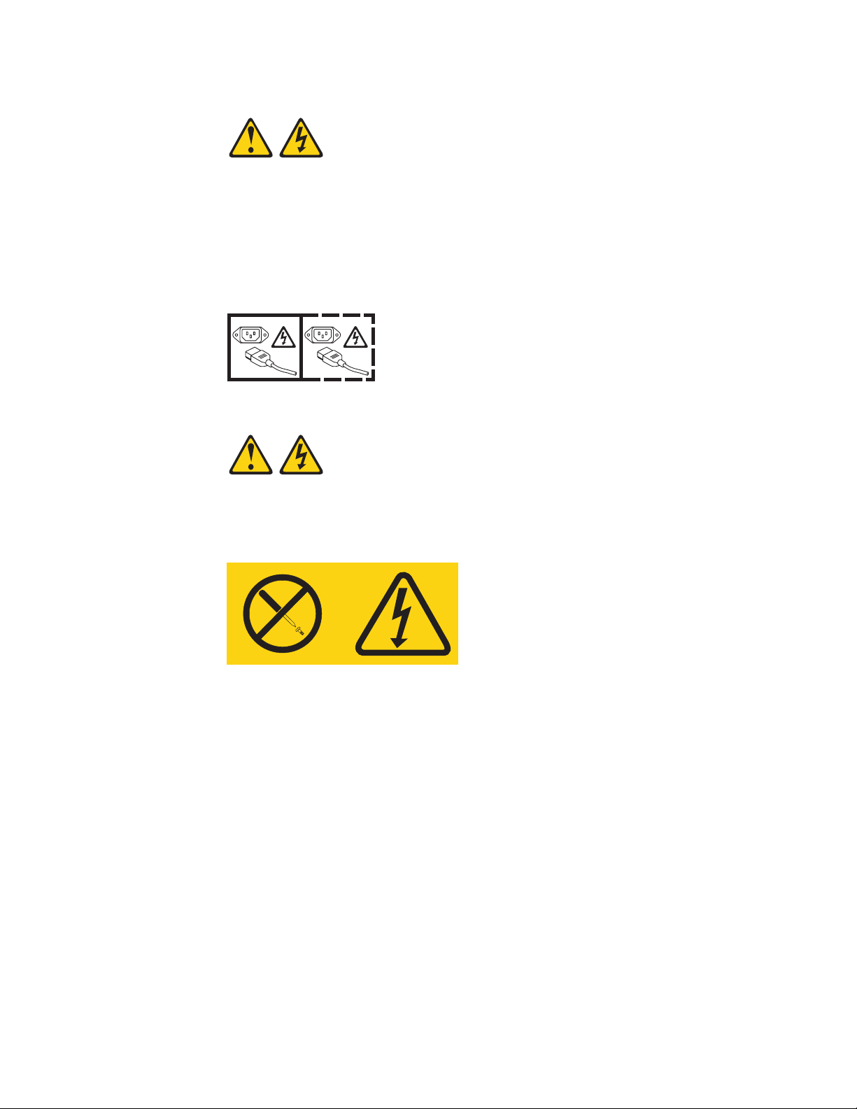
Statement 5:
CAUTION:
The power control button on the device and the power switch on the power
supply do not turn off the electrical current supplied to the device. The device
also might have more than one power cord. To remove all electrical current
from the device, ensure that all power cords are disconnected from the power
source.
1 2
Statement 8:
CAUTION:
Never remove the cover on a power supply or any part that has the following
label attached.
Hazardous voltage, current, and energy levels are present inside any
component that has this label attached. There are no serviceable parts inside
these components. If you suspect a problem with one of these parts, contact
a service technician.
viii IBM iDataPlex dx360 User's Guide
Page 11

Statement 10:
CAUTION:
Do not place any object on top of rack-mounted devices.
Safety ix
Page 12

x IBM iDataPlex dx360 User's Guide
Page 13

Chapter 1. Introduction
IBM® System x™ iDataPlex™ products are ideally suited for data-center
environments that require high-performance, energy-efficient, cost-effective
hardware. The modular design of the iDataPlex components makes it possible for
you to order customized server solutions that meet the specific needs of your
current environment.
This User's Guide contains general information about how to use, upgrade, and
configure the components in the customized server solutions. These components
consist of the IBM System x iDataPlex dx360 Type 6316, 6390, or 7833
system-board tray, the IBM System x iDataPlex Types 6313, 6385, or 7831 2U flex
chassis, and the IBM System x iDataPlex storage enclosure.
With the exception of the warranty period, the iDataPlex Types 6313, 6316, 6385,
6390, 7831, and 7833 products are functionally equivalent as follows:
v IBM System x iDataPlex dx360 system-board tray Types 6316, 6390, and 7833
are functionally equivalent
v IBM System x iDataPlex 2U flex chassis Types 6313, 6385, and 7831 are
functionally equivalent
Depending on what you ordered, you received one or more of the following server
solutions:
v Two dx360 system-board trays installed in a 2U chassis
v One dx360 system-board tray and one storage enclosure installed in a 2U
chassis
See Chapter 2, “Components, features, and controls,” on page 9 for detailed
information about the components in the customized server solutions.
The iDataPlex products come with a limited warranty. For information about the
terms of the warranty and getting service and assistance, see the Warranty and
Support Information document.
You can obtain up-to-date information about the server and other IBM server
products at http://www.ibm.com/systems/x/.
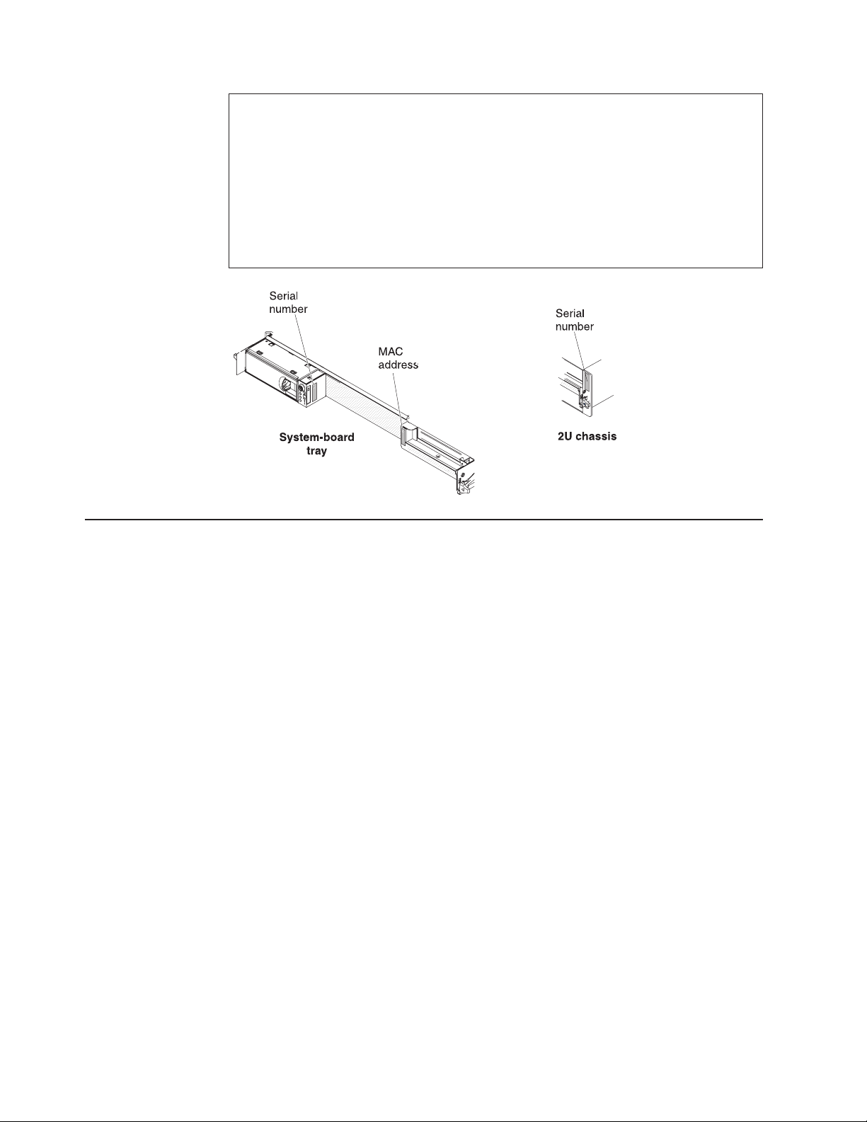
The system-board tray serial number is on a label at the front of the system-board
tray to the left of the operator panel. The system-board tray baseboard
management controller (BMC) media access control (MAC) address is on a label at
the front of the system-board tray to the left of the PCIe slot. The chassis machine
type and serial number are on a label on the front of the chassis at the right side.
Label locations are shown in the illustration following the table. This illustration
might differ slightly from your hardware.
Record information about the server in the following table.
© Copyright IBM Corp. 2011 1
Page 14
Product name IBM System x iDataPlex dx360
Machine type
(system-board tray)
Serial number
(system-board tray)
BMC MAC address
(system-board tray)
Machine type (chassis) Type ______ (2U chassis)
Serial number (chassis) _____________________________________________
Type ______
_____________________________________________
_____________________________________________
Related documentation
In addition to the printed Important Notices document and this User's Guide, the
following documentation for the dx360 system-board tray and 2U flex chassis is
provided in Portable Document Format (PDF) on the IBM Documentation CD:
v Warranty and Support Information
This document contains information about the terms of the warranty and getting
service and assistance.
v Safety Information
This document contains translated caution and danger statements. Each caution
and danger statement that appears in the documentation has a number that you
can use to locate the corresponding statement in your language in the Safety
Information document.
v Problem Determination and Service Guide
This document contains information to help you solve problems yourself, and it
contains information for service technicians.
Depending on the hardware configuration, additional documentation might be
included on the IBM Documentation CD.
The iDataPlex documentation might be updated occasionally, or technical updates
might be available to provide additional information that is not included in the
documentation. These updates are available from the IBM Systems Information
Center. To check for updated iDataPlex information and technical updates, go to
http://publib.boulder.ibm.com/infocenter/idataplx/documentation/index.jsp .
The updated iDataPlex documentation also is available from the IBM Support Web
site. To check for updated documentation and technical updates, complete the
following steps.
2 IBM iDataPlex dx360 User's Guide
Page 15

Note: Changes are made periodically to the IBM Web site. The actual procedure
might vary slightly from what is described in this document.
1. Go to http://www.ibm.com/systems/support/.
2. Under Product support, click System x.
3. Under Popular links, click Publications lookup.
4. From the Product family menu, select System x iDataPlex dx360 server and
click Go.
The IBM Documentation CD
The IBM Documentation CD contains documentation in Portable Document Format
(PDF) and includes the IBM Documentation Browser to help you find information
quickly.
Hardware and software requirements
The IBM Documentation CD requires the following minimum hardware and
software:
v Microsoft Windows XP, Windows 2000, or Red Hat Linux
v 100 MHz microprocessor
v 32 MB of RAM
v Adobe Acrobat Reader 3.0 (or later) or xpdf, which comes with Linux operating
systems
Using the Documentation Browser
Use the Documentation Browser to browse the contents of the CD, read brief
descriptions of the documents, and view documents, using Adobe Acrobat Reader
or xpdf. The Documentation Browser automatically detects the regional settings in
your server and displays the documents in the language for that region (if
available). If a document is not available in the language for that region, the
English-language version is displayed.
Use one of the following procedures to start the Documentation Browser:
v If Autostart is enabled, insert the CD into the CD or DVD drive. The
Documentation Browser starts automatically.
v If Autostart is disabled or is not enabled for all users, use one of the following
procedures:
– If you are using a Windows operating system, insert the CD into the CD or
DVD drive and click Start --> Run. In the Open field, type
e:\win32.bat
where e is the drive letter of the CD or DVD drive, and click OK.
– If you are using Red Hat Linux, insert the CD into the CD or DVD drive; then,
run the following command from the /mnt/cdrom directory:
sh runlinux.sh
Select the device from the Product menu. The Available Topics list displays all the
documents for the devices. Some documents might be in folders. A plus sign (+)
indicates each folder or document that has additional documents under it. Click the
plus sign to display the additional documents.
When you select a document, a description of the document is displayed under
Topic Description. To select more than one document, press and hold the Ctrl key
Chapter 1. Introduction 3
Page 16

while you select the documents. Click View Book to view the selected document or
documents in Acrobat Reader or xpdf. If you selected more than one document, all
the selected documents are opened in Acrobat Reader or xpdf.
To search all the documents, type a word or word string in the Search field and
click Search. The documents in which the word or word string appears are listed in
order of the most occurrences. Click a document to view it, and press Crtl+F to use
the Acrobat search function, or press Alt+F to use the xpdf search function within
the document.
Click Help for detailed information about using the Documentation Browser.
Notices and statements in this document
The caution and danger statements in this document are also in the multilingual
Safety Information document, which is on the IBM Documentation CD. Each
statement is numbered for reference to the corresponding statement in your
language in the Safety Information document.
The following notices and statements are used in this document:
v Note: These notices provide important tips, guidance, or advice.
v Important: These notices provide information or advice that might help you avoid
inconvenient or problem situations.
v Attention: These notices indicate potential damage to programs, devices, or
data. An attention notice is placed just before the instruction or situation in which
damage might occur.
v Caution: These statements indicate situations that can be potentially hazardous
to you. A caution statement is placed just before the description of a potentially
hazardous procedure step or situation.
v Danger: These statements indicate situations that can be potentially lethal or
extremely hazardous to you. A danger statement is placed just before the
description of a potentially lethal or extremely hazardous procedure step or
situation.
4 IBM iDataPlex dx360 User's Guide
Page 17

Features and specifications
The following information is a summary of the features and specifications of the
hardware. Depending on the hardware configuration, some features might not be
available, or some specifications might not apply.
Racks are marked in vertical increments of 4.45 cm (1.75 inches). Each increment
is referred to as a unit, or “U.” A 1U-high device is 1.75 inches tall.
Table 1. Features and specifications
Microprocessor: Supports two
dual-core or quad-core Intel Xeon
microprocessors in each system-board
tray
Note: Use the BIOS Setup Utility
program to determine the type and
speed of the microprocessor.
Memory:
v Four-channel DIMMs: 16 DIMM
connectors
v Types: Fully buffered double-data
rate (DDR2) 667 MHz DIMMs with
AMB+ or DDR2 800 MHz DIMMs
with AMB+
v Supports 2 GB and 4 GB DIMMs
(as of the date of this publication)
with up to 64 GB of total memory in
each system-board tray
Hard disk drives:
v The system-board tray supports
one 3.5-inch simple-swap SAS or
one 3.5-inch simple-swap SATA
hard disk drive.
v The system-board tray with a
storage enclosure attached can
support up to four 3.5-inch
simple-swap SAS hard disk drives
or up to five 3.5-inch simple-swap
SATA hard disk drives.
PCI expansion slots:
v Each system-board tray supports
one PCIe expansion slot
Integrated functions:
v Intel baseboard management
controller (BMC) with Intelligent
Platform Management Interface
(IPMI) 2.0 compliant firmware
v ATI ES1000 video controller with
32 MB DDR2 SDRAM
v Dual 10 Mb/100 Mb/1 GB network
interface controllers
v Wake on LAN support
v I/O Controller with six Serial ATA
(SATA) ports
v Front panel connectors:
– Two Universal Serial Bus
– One systems management
– VGA video port
– Two Ethernet ports
(USB) 2.0 ports
serial port
Size (2U chassis):
v Height: 86 mm (3.386 inches)
v Depth: 473 mm (18.6 inches)
v Width: 446 mm (17.56 inches)
v Maximum weight: 6.98 kg (15.5 lb)
Environment:
v Air temperature:
– Server on: 10°C to 35°C (50°F to
95°F); altitude: 0 to 914.4 m (0 to
3000 ft). Derate maximum
temperature by 1°C for every
304.8 m (1000 ft) increase in
elevation to a maximum of
3,048.0 m (10000 ft) at an
ambient temperature of 28°C.
– Server off: 10°C to 43°C (59°F to
109.4°F); maximum altitude: 2133
m (7000 ft)
v Humidity:
– Server on: 10% to 80%
– Server off: 8% to 80%
Electrical Input:
v Input voltage low range: 100 V ac
(minimum) to 127 V ac (maximum),
50 to 60 Hz, sine-wave input
v Input voltage high range: 200 V ac
(minimum) to 240 V ac (maximum),
50 to 60 Hz, sine-wave input
Chapter 1. Introduction 5
Page 18

What your dx360 system-board tray offers
The dx360 system board uses the following features and technologies:
v Active PCI Express x16 adapter capabilities
The dx360 system-board tray has one connector for PCI Express Generation two
x16 adapters.
v Baseboard management controller
The Intel baseboard management controller provides basic service-processor
environmental monitoring functions. If an environmental condition exceeds a
threshold or if a system component fails, the baseboard management controller
lights LEDs to help you diagnose the problem and records the error in the error
log. The baseboard management controller also provides remote server
management capabilities, using the Intelligent Platform Management Interface
(IPMI) version 2.0 protocol.
Note: In messages and documentation, the term service processor refers to the
baseboard management controller.
v Dynamic System Analysis (DSA) programs
The DSA programs collect and analyze system information to aid in diagnosing
problems. The diagnostic programs collect the following information:
– System configuration
– Network interfaces and settings
– Installed hardware
– Service processor status and configuration
– Vital product data, firmware, and BIOS configuration
– Hard disk drive health
The diagnostic programs create a merged log that includes events from all
collected logs. The information is collected into a file that you can send to IBM
service and support. Additionally, you can view the information locally through a
generated text report file. You also can copy the log to removable media and
view the log from a Web browser.
v High-performance graphics controller
The server comes with an integrated graphics controller. This high-performance
controller supports high resolutions and includes many performance-enhancing
features for the operating-system environment.
v Integrated network support
The server comes with dual integrated Gigabit Ethernet controllers, which support
connections to a 10 Mbps, 100 Mbps, or 1000 Mbps network. For more
information, see “Configuring the Gigabit Ethernet controller” on page 38.
v Large data-storage capacity
The dx360 supports one 3.5-inch simple-swap SAS or SATA hard disk drive in
the system-board tray. With the storage enclosure attached, the dx360 can
support up to four simple-swap SAS hard disk drives or up to five simple-swap
SATA hard disk drives.
v Large system-memory capacity
The dx360 supports up to 64 GB of system memory. The memory controller
supports error correcting code (ECC) for up to sixteen industry-standard, 240-pin,
double-data-rate 2 (DDR2) 667 MHz or 800 MHz, fully-buffered dual inline
memory modules (DIMMs).
6 IBM iDataPlex dx360 User's Guide
Page 19

v Redundant connection
The system-board tray provides a failover capability to a redundant Ethernet
connection. If a problem occurs with the primary Ethernet connection, all Ethernet
traffic that is associated with the primary connection is automatically switched to
the redundant NIC. If the applicable device drivers are installed, this switching
occurs without data loss and without user intervention.
v Symmetric multiprocessing (SMP)
The dx360 comes with two Intel dual-core or quad-core Xeon microprocessors.
v Systems-management capabilities
The dx360 supports IPMI version 2.0 over LAN system management protocol. It
supports an optional rack-level management controller that uses
industry-standard management tools.
Reliability, availability, and serviceability
Three important hardware and software design features are reliability, availability,
and serviceability (RAS). The RAS features help to ensure the integrity of the data
that is stored in the hardware, the availability of the hardware and software when
you need it, and the ease with which you can diagnose and correct problems.
The dx360 system-board tray has the following RAS features:
v Advanced Configuration and Power Interface (ACPI)
v Advanced Desktop Management Interface (DMI) features
v Automatic error retry or recovery
v Automatic memory downsizing on error detection
v Automatic restart on nonmaskable interrupt (NMI)
v Automatic Server Restart (ASR) logic supporting a system restart when the
operating system becomes unresponsive
v Automatic restart after a power failure, based on the BIOS setting
v Boot-block recovery
v Built-in monitoring for fan, power, temperature, and voltage
v Customer support center that is available 24 hours a day, 7 days a week
v Error codes and messages
v Memory change messages posted to the error log
v Power-on self-test (POST) with error logging of POST failures
v Power management
v Integrated Ethernet controllers
v Read-only memory (ROM) checksums
v Redundant Ethernet capabilities with failover support
v Simple-swap Serial Attached SCSI (SAS) hard disk drives
v Simple-swap Serial Advanced Technology Attachment (SATA) hard disk drives
v Standby voltage for systems-management features and monitoring
v System auto-configuring from the configuration menu
v System-error LED on the front bezel
v Upgradeable BMC firmware
1
1. Service availability will vary by country. Response time varies; may exclude holidays.
Chapter 1. Introduction
7
Page 20

v Upgradeable microcode for POST, basic input/output system (BIOS) code, and
read-only memory (ROM) resident code, locally or over a LAN
v Vital product data (VPD); includes serial-number information and replacement
part numbers, stored in nonvolatile memory, for easier remote maintenance
v Wake on LAN capability
The UpdateXpress program
The UpdateXpress program detects supported and installed device drivers and
firmware in the server and installs available updates. You can download the
UpdateXpress program from the Web at no additional cost, or you can purchase it
on a CD. To download the program or purchase the CD, go to
http://www.ibm.com/systems/management/xpress.html. Additional information about
UpdateXpress is available from the Tools Center at http://publib.boulder.ibm.com/
infocenter/toolsctr/v1r0/index.jsp.
Note: To install the UpdateXpress program, you might need to use an external
USB CD-RW/DVD drive such as the IBM and Lenovo part number 73P4515 or
73P4516. See “Firmware updates” on page 39 for additional instructions about
using an external USB CD-RW/DVD drive.
8 IBM iDataPlex dx360 User's Guide
Page 21
Chapter 2. Components, features, and controls
This section describes the server components and configurations, the server
controls and light-emitting diodes (LEDs), and how to turn the system-board tray on
and off.
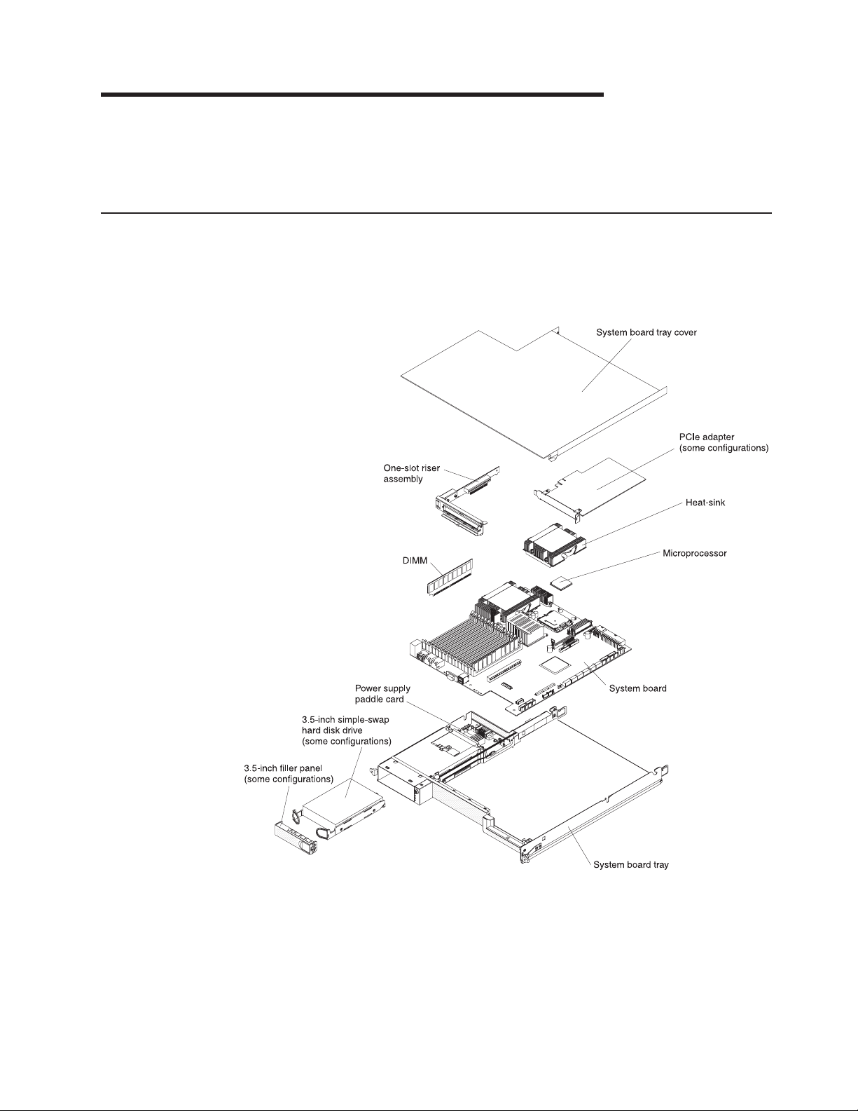
System-board tray components
The following illustration shows the major components in the dx360 system-board
tray.
Note: The illustrations in this document might differ slightly from your hardware.
© Copyright IBM Corp. 2011 9
Page 22

System-board connectors
The following illustration shows the locations of internal connectors on the system
board that are used for installing options. See “Operator panel controls, LEDs,
connectors, and power” on page 13 for information about the external connectors.
See the Problem Determination and Service Guide for information about the other
system-board connectors.
10 IBM iDataPlex dx360 User's Guide
Page 23

System-board switches and jumpers
The following illustration shows the locations of the jumpers on the system board
that relate to selected system functions. See the Problem Determination and
Service Guide for more information about using switches and jumpers on the
system board.
Chapter 2. Components, features, and controls 11
Page 24

Flexible chassis features
The following illustration shows an IBM System x iDataPlex 2U flex chassis. The 2U
chassis contains a power supply and a fan assembly that provide operating power
and cooling for all components in the chassis. The 2U chassis can support two
system-board trays or one system-board tray with a storage enclosure.
Note: The illustrations in this document might differ slightly from your hardware.
Fan assembly
cover
Power supply
Hardware configuration examples
The iDataPlex 2U flex chassis supports the following dx360 server configurations:
v 2U compute server: A 2U chassis that contains two dx360 system-board trays
v 2U storage server: A 2U chassis that contains one dx360 system-board tray and
an optional storage enclosure
Note: The illustrations in this document might differ slightly from your hardware.
Fan assembly
2U chassis
12 IBM iDataPlex dx360 User's Guide
Page 25

2U compute server
The 2U compute server consists of two identical dx360 system-board trays installed
in a 2U flex chassis. Each system-board tray has one PCIe adapter connector and
one 3.5–inch hard disk drive bay.
2U storage server
The 2U storage server consists of one dx360 system-board tray with the storage
enclosure installed in a 2U flex chassis. The storage enclosure provides four
additional 3.5–inch hard disk drive bays for the system-board tray, for a total of five.
Depending on the server configuration, you can configure the 2U storage server
with up to four 3.5–inch simple-swap SAS hard disk drives or up to five 3.5–inch
simple-swap SATA hard disk drives.
Operator panel controls, LEDs, connectors, and power
The following illustration shows the controls, LEDs, and connectors on the front of
the dx360 system-board tray. The operator panel on the system-board tray is the
same for all dx360 server configurations.
Power-control button: Press this button to turn the system-board tray on and off
manually.
Chapter 2. Components, features, and controls 13
Page 26

Note: You can also remove the power-control button cover for easier access to the
power-control button.
Ethernet link activity/status LED: This LED is on each Ethernet connector. It
indicates that there is an active connection on the Ethernet port. When this LED is
flashing, it indicates that there is activity between the server and the network.
Ethernet connection speed LED: This LED is on each Ethernet connector. The
status of this LED indicates the connection speed between the system-board tray
and the network as follows:
v LED off: 10 Mbps connection
v LED lit Amber: 100 Mbps connection
v LED lit Green: 1000 Mbps connection
USB connectors: Connect USB 2.0 devices to these connectors.
Video connector: Connect a monitor to this connector.
Ethernet connectors: Use these connectors to connect the server to a network.
Systems management port: Connect a systems management device to this serial
connector.
Locator LED: This LED can be lit remotely by the system administrator to aid in
visually locating the server.
System-error LED: When this LED is lit, it indicates that a system error has
occurred. The source of the error is logged in the BMC system-event log that is
accessed in the BIOS Setup Utility program.
Hard disk drive activity LED: When this LED is flashing, it indicates that an
associated hard disk drive is in use.
Power-on LED: When this LED is lit, it indicates that the system-board tray is
turned on. When this LED is off, it indicates that ac power is not present or the
power supply or the LED itself has failed.
Note: If this LED is off, it does not mean that no electrical power is present. The
LED might be burned out. To remove all electrical power, you must disconnect the
power cord from the chassis.
14 IBM iDataPlex dx360 User's Guide
Page 27

Rear connectors
Power-cord connector: Connect the power cord to this connector. When the
chassis is installed in an iDataPlex rack, it is connected automatically to power
through a power cord that is mounted to the rack rail.
Chapter 2. Components, features, and controls 15
Page 28

Turning on the system-board tray
After you install the system-board tray in a chassis, the system-board tray can start
in any of the following ways:
Important: To avoid potential problems during startup, disconnect any USB keys
from the system that contain the Smart Launch Utility before you turn on the
system-board tray.
v You can press the power-control button on the front of the system-board tray
(see “Operator panel controls, LEDs, connectors, and power” on page 13) to start
the system-board tray.
v In an IPMI environment, the system administrator can turn on the system-board
tray using the BMC IPMI Chassis Control command. See “Setting the BMC IP
parameters” on page 40 for instructions to display or change baseboard
management controller IP parameters.
v If a power failure occurs, the system-board tray can start automatically when
power is restored, if it is configured to do so.
Turning off the system-board tray
When you turn off the system-board tray, it is still connected to power through the
chassis power supply. The system-board tray still can respond to requests from the
service processor, such as a remote request to turn on the system-board tray. To
remove all power from the system-board tray, you must remove the tray from the
chassis.
Shut down the operating system before you turn off the system-board tray. See the
operating-system documentation for information about shutting down the operating
system.
The system-board tray can be turned off in any of the following ways:
v You can press the power-control button on the front of the system-board tray
(see “Operator panel controls, LEDs, connectors, and power” on page 13). This
starts an orderly shutdown of the operating system, if this feature is supported by
the operating system.
v You can turn off the system-board tray from the operating system, if the operating
system supports this feature. After an orderly shutdown of the operating system,
the system-board tray will be turned off automatically.
v In an IPMI environment, the system administrator can turn off the system-board
tray by using the BMC IPMI Chassis Control command.
v If the operating system stops functioning, you can press and hold the
power-control button for more than 4 seconds to turn off the system-board tray.
v You might be able to turn off the system-board tray by using an optional
management appliance.
– If the system is not operating correctly, the management appliance might
automatically turn off the system-board tray.
– Through the management appliance control interface, you might also be able
to configure the management appliance to turn off the system-board tray. For
additional information, see the documentation for your management appliance.
16 IBM iDataPlex dx360 User's Guide
Page 29

Chapter 3. Installing optional devices
This section provides detailed instructions for installing optional hardware devices.
Installation guidelines
Before you install optional devices, read the following information:
v Read the safety information that begins on page v and “Handling static-sensitive
devices” on page 18. This information will help you work safely.
v Before you install optional hardware devices, make sure that the server is
working correctly. Start the server, and make sure that the operating system
starts, if an operating system is installed, or that a I9990305 error code is
displayed, indicating that an operating system was not found but the server is
otherwise working correctly. If the server is not working correctly, see the
Problem Determination and Service Guide for diagnostic information.
v Observe good housekeeping in the area where you are working. Place removed
covers and other parts in a safe place.
v Do not attempt to lift an object that you think is too heavy for you. If you have to
lift a heavy object, observe the following precautions:
– Make sure that you can stand safely without slipping.
– Distribute the weight of the object equally between your feet.
– Use a slow lifting force. Never move suddenly or twist when you lift a heavy
object.
– To avoid straining the muscles in your back, lift by standing or by pushing up
with your leg muscles.
v Back up all important data before you make changes to disk drives.
v Have a small flat-blade screwdriver and a small Phillips screwdriver available.
v You do not have to turn off the system-board tray to install or replace hot-plug
Universal Serial Bus (USB) devices. However, you must shut down the operating
system and turn off the system-board tray before you install or remove
simple-swap drives.
v Blue on a component indicates touch points, where you can grip the component
to remove it from or install it in the server, open or close a latch, and so on.
v Orange on a component or an orange label on or near a component indicates
that the component can be hot-swapped, which means that if the server and
operating system support hot-swap capability, you can remove or install the
component while the server is running. (Orange can also indicate touch points on
hot-swap components.) See the instructions for removing or installing a specific
hot-swap component for any additional procedures that you might have to
perform before you remove or install the component.
© Copyright IBM Corp. 2011 17
Page 30

System reliability guidelines
To help ensure proper cooling and system reliability, make sure that the following
requirements are met:
v Each of the drive bays has a drive or a filler panel and electromagnetic
compatibility (EMC) shield installed in it.
v You have followed the cabling instructions that come with optional adapters.
v The system-board tray battery is operational. If the battery becomes defective,
replace it immediately.
Handling static-sensitive devices
Attention: Static electricity can damage the server and other electronic devices.
To avoid damage, keep static-sensitive devices in their static-protective packages
until you are ready to install them.
To reduce the possibility of damage from electrostatic discharge, observe the
following precautions:
v Limit your movement. Movement can cause static electricity to build up around
you.
v The use of a grounding system is recommended. For example, wear an
electrostatic-discharge wrist strap, if one is available.
v Handle the device carefully, holding it by its edges or its frame.
v Do not touch solder joints, pins, or exposed circuitry.
v Do not leave the device where others can handle and damage it.
v While the device is still in its static-protective package, touch it to an unpainted
metal surface on the outside of the chassis or rack for at least 2 seconds. This
drains static electricity from the package and from your body.
v Remove the device from its package and install it directly into the system-board
tray or storage enclosure without setting down the device. If it is necessary to set
down the device, put it back into its static-protective package. Do not place the
device on a metal surface.
v Take additional care when you handle devices during cold weather. Heating
reduces indoor humidity and increases static electricity.
18 IBM iDataPlex dx360 User's Guide
Page 31

Removing a system-board tray from a 2U chassis
Attention: When two system-board trays are installed in the chassis, do not
operate the upper system-board tray with the bottom system-board tray removed or
powered off, except for servicing. When the bottom system-board tray is removed
or powered-off, chassis-level system management information is not read correctly.
For example, chassis fan speeds and temperatures might be returned as zero
values. In this situation, the unit will continue to operate normally, since the power
supply and fans are designed to operate independently.
Notes:
1. If two system-board trays are installed in the chassis, they can be removed
independently of each other.
2. If a storage enclosure is installed on the system-board tray, you will remove the
storage enclosure and the system-board tray from the chassis as one assembly.
To remove a system-board tray from the chassis, complete the following steps.
1. Read the safety information that begins on page v and “Installation guidelines”
on page 17.
2. Turn off the system-board tray and all attached devices (see “Turning off the
system-board tray” on page 16).
3. If external cables are connected to the front of the system-board tray, note
where they are connected; then, remove them.
4. Press in on the two release handles, pull the system-board tray and storage
enclosure, if one is attached, out of the chassis, and set it on a flat,
static-protective surface.
Chapter 3. Installing optional devices 19
Page 32

Removing the system-board tray cover
Note: If a storage enclosure is installed on the system-board tray, remove it (see
“Removing a storage enclosure” on page 21).
System-board
tray cover
System-board
tray
Release
latch
To remove the system-board tray cover, complete the following steps:
1. Read the safety information that begins on page v and “Installation guidelines”
on page 17.
2. Turn off the system-board tray and all attached devices (see “Turning off the
system-board tray” on page 16).
3. If the system-board tray is installed in a chassis, remove it (see “Removing a
system-board tray from a 2U chassis” on page 19).
4. Carefully set the system-board tray on a flat, static-protective surface, with the
cover side up.
5. Pull the cover release latch on each side of the system-board tray upward; then,
lift the cover open.
6. Lift the cover off the system-board tray and store it for future use.
Note: If two system-board trays are installed in a 2U chassis, both must have their
covers installed.
20 IBM iDataPlex dx360 User's Guide
Page 33

Removing a storage enclosure
To remove a storage enclosure from the system-board tray, complete the following
steps:
1. Read the safety information that begins on page v and “Installation guidelines”
on page 17.
2. Turn off the system-board tray and all attached devices (see “Turning off the
system-board tray” on page 16).
3. If the system-board tray is installed in a chassis, remove it (see “Removing a
system-board tray from a 2U chassis” on page 19).
4. Carefully set the system-board tray on a flat, static-protective surface.
5. Note the cable routing and connection locations; then, disconnect the cables
that connect the storage enclosure to the system-board tray.
6. Pull the release latch on each side of the system-board tray outward; then,
rotate the storage enclosure open.
7. Using care not to pull on the cables, lift the storage enclosure from the
system-board tray and carefully set it on a flat, static-protective surface.
Chapter 3. Installing optional devices 21
Page 34

Removing a 3.5-inch simple-swap hard disk drive
Note: The following illustration shows how to remove a 3.5-inch simple-swap hard
disk drive from a storage enclosure. Removing a 3.5-inch simple-swap hard disk
drive from a system-board tray is similar.
To remove a simple-swap hard disk drive, complete the following steps:
1. Read the safety information that begins on page v and “Installation guidelines”
on page 17.
2. Turn off the system-board tray and all attached devices (see “Turning off the
system-board tray” on page 16).
3. Remove the filler panel from the simple-swap hard disk drive bay.
4. Pull the loops of the drive toward each other; then, pull the drive out of the drive
bay.
Note: A hard disk drive or filler panel must always be installed in each drive
bay when the server is turned on. Simple-swap disk drives must always have a
filler panel installed along with the hard disk drive.
5. Store the drive and filler panel for later use.
22 IBM iDataPlex dx360 User's Guide
Page 35

Installing an adapter
The following notes describe the types of adapters that the server supports and
other information that you must consider when you install an adapter:
v Locate the documentation that comes with the adapter and follow those
instructions in addition to the instructions in this section. If you have to change
the switch setting or jumper settings on the adapter, follow the instructions that
come with the adapter.
v The server comes with a one-slot PCI Express (PCIe) riser card. The riser card
slot supports PCIe x16 adapters.
Notes:
1. The one-slot riser card supports installation of only half-length, full-height
adapters.
2. The maximum power consumption from all supply voltages for a single PCIe
slot is the same as specified in PCI Local Bus Specification Revision 2.3 for
conventional slots (25 W).
To install an adapter in the system-board tray, complete the following steps:
1. Read the safety information that begins on page v and “Installation guidelines”
on page 17.
2. Turn off the system-board tray and all attached devices (see “Turning off the
system-board tray” on page 16).
3. If the system-board tray is installed in a chassis, remove it (see “Removing a
system-board tray from a 2U chassis” on page 19).
4. If a storage enclosure is installed on the system-board tray, remove it (see
“Removing a storage enclosure” on page 21); otherwise, remove the
system-board tray cover (see “Removing the system-board tray cover” on page
20).
5. Remove the riser card retaining screw on the front of the system-board tray.
Store the screw for future use.
Chapter 3. Installing optional devices 23
Page 36

Note: If an adapter is already installed in the riser card, the riser card and
adapter are removed together.
6. Carefully grasp the one-slot riser card by its top edge or upper corners, and
pull the riser card straight up and out of the system-board tray.
7. Carefully set the riser card on a flat, static-protective surface. If an adapter is
installed in the riser card, remove it.
8. Touch the static-protective package that contains the adapter that you are
installing to any unpainted metal surface on the system-board tray; then,
remove the adapter from the static-protective package. Avoid touching the
components and gold-edge connectors on the adapter.
9. Follow the instructions that come with the adapter to set any jumpers or
switches.
10. Carefully grasp the adapter by the top edge or upper corner and insert it in the
one-slot riser card. Align the adapter with the riser card connector; then, press
the adapter firmly into the connector.
Note: Make sure that the adapter is inserted correctly. Improper installation of
an adapter might damage the PCIe riser-card assembly or the adapter.
11. Follow the cabling instructions, if any, that come with the adapter. If possible,
route the adapter cables before you install the adapter.
12. Pinch the two sides of the one-slot riser card, and align the riser card with the
riser-card connector on the system board; then, press the riser card firmly,
evenly with both hands, into the connector.
13. Install the riser card retaining screw at the front of the system-board tray.
If you have other devices to install or remove, do so now. Otherwise, go to
“Completing the installation” on page 30.
24 IBM iDataPlex dx360 User's Guide
Page 37

Installing a 3.5-inch simple-swap hard disk drive
Note: The following illustration shows how to install a 3.5-inch simple-swap hard
disk drive in a storage enclosure. Installing a 3.5-inch simple-swap hard disk drive
in the system-board tray is similar.
To install a 3.5-inch simple-swap hard disk drive, complete the following steps:
1. Read the safety information that begins on page v and “Installation guidelines”
on page 17.
2. Turn off the system-board tray and all attached devices (see “Turning off the
system-board tray” on page 16).
3. Remove the filler panel from the simple-swap hard disk drive bay.
4. Touch the static-protective package that contains the hard disk drive to any
unpainted metal surface on the outside of the system-board tray for at least 2
seconds; then, remove the hard disk drive from the package.
Attention: Do not press on the top of the drive. Pressing the top might
damage the drive.
5. Align the drive with the guide rails in the drive bay.
6. Pull the loops of the drive toward each other; then, carefully slide the drive into
the bay until it stops, and release the loops.
Note: Do not release the loops on the drive until it is completely seated.
7. Install the filler panel in the simple-swap hard disk drive bay.
If you have other devices to install, do so now. Otherwise, turn on the system-board
tray (see “Turning on the system-board tray” on page 16).
Note: If the server has a PCIe RAID adapter and you install or remove a hard disk
drive, see the documentation that comes with your RAID adapter for more
information about re-configuring the disk arrays.
Chapter 3. Installing optional devices 25
Page 38

Installing a memory module
The following paragraphs describe the types of dual inline memory modules
(DIMMs) that the system-board tray supports and other information that you must
consider when you install DIMMs.
v The system-board tray supports only industry-standard, 1.8 V, 240-pin
double-data-rate 2 (DDR2), 667 MHz or 800 MHz, fully-buffered, dual inline
memory modules (DIMMs) with error correcting code (ECC). These DIMMs must
be compatible with the latest DDR2 buffered DIMM specification.
v The server supports a minimum of 2 GB and a maximum of 64 GB of system
memory.
v The amount of usable memory depends on the system configuration. Some
memory is reserved for system resources. To view the total amount of installed
memory and the amount of configured memory, run the Configuration/Setup
Utility program and select System Summary from the menu. For additional
information, see Chapter 4, “Configuring the dx360 server,” on page 35.
v When you restart the server after you add or remove a DIMM, the server
displays a message that the memory configuration has changed.
The dx360 system board contains sixteen DIMM connectors organized into four
fully-buffered DIMM memory channels (A, B, C, and D) and two branches (0 and 1).
Each branch is supported by a separate memory controller.
The following illustration shows DIMM slot organization on the dx360 system board.
26 IBM iDataPlex dx360 User's Guide
Page 39

The following table shows the DIMM configurations that are supported for the dx360
server.
Table 2. Supported DIMM configurations
Branch 0 Branch 1
Channel A Channel B Channel C Channel D
A1 A2 A3 A4 B1 B2 B3 B4 C1 C2 C3 C4 D1 D2 D3 D4
X X
X X X X
X X X X X X X X
X X X X X X X X X X X X X X X X
Legend:
X Slot is populated: Supported configuration.
Slot is not populated.
DIMM slot population rules for the dx360 server are as follows:
v Within a branch, DIMMs must be populated in slot order starting with Slot 1 for
each channel, followed by slot 2, then slot 3, and ending with slot 4.
v DIMMs must be populated in matching pairs across channels within a given
branch. Therefore, when populating DIMM pairs, the population order would be
as follows:
A1 and B1; C1 and D1; A2 and B2; C2 and D2; A3 and B3; C3 and D3; A4 and
B4; C4 and D4
v DIMMs that make up a given pair must match with respect to size, speed, and
organization.
v DIMM size can vary from one DIMM pair to another, however, speed and
organization must be the same. For example, DIMM Pair A1 and B1 are
populated with x8 1GB DDR2-667 DIMMs. DIMM Pair C1 and D1 can be
populated with x8 2GB DDR2-667 DIMMs.
Notes:
1. For best performance, the number of DIMMs installed should be balanced
across both memory branches. For example, a four DIMM configuration will
perform better than a two DIMM configuration and should be installed in DIMM
Slots A1, B1, C1, and D1. An eight DIMM configuration will perform better than
a six DIMM configuration.
2. The minimum memory upgrade increment is two DIMMs per branch. The DIMM
options that are available for the server are 2 GB and 4 GB.
v DIMMs must cover the same slot position on both channels.
v DIMM pairs must be identical with respect to size, speed, and organization.
v DIMMs that cover adjacent slot positions do not need to be identical.
The following illustration shows the dual inline memory module (DIMM) connectors
on the system board.
Chapter 3. Installing optional devices 27
Page 40

To install a DIMM, complete the following steps:
1. Read the safety information that begins on page v and “Installation guidelines”
on page 17.
2. Turn off the system-board tray and all attached devices (see “Turning off the
system-board tray” on page 16).
3. Make note of where the cables are attached on the front of the system-board
tray; then, disconnect them.
4. If the system-board tray is installed in a chassis, remove it (see “Removing a
system-board tray from a 2U chassis” on page 19).
5. If a storage enclosure is installed on the system-board tray, remove it (see
“Removing a storage enclosure” on page 21). Otherwise, remove the
system-board tray cover (see “Removing the system-board tray cover” on page
20).
6. Locate the DIMM connectors on the system board. Determine the connectors
into which you will install the DIMMs.
Attention: To avoid breaking the retaining clips or damaging the DIMM
connectors, open and close the clips gently.
7. Open the retaining clips and, if necessary, remove any existing DIMM.
28 IBM iDataPlex dx360 User's Guide
Page 41

8. Touch the static-protective package that contains the DIMM to any unpainted
metal surface on the system-board tray. Then, remove the new DIMM from the
package.
9. Turn the DIMM so that the DIMM keys align correctly with the connector.
10. Insert the DIMM into the connector by aligning the edges of the DIMM with the
slots at the ends of the DIMM connector. Firmly press the DIMM straight down
into the connector by applying pressure on the top of the DIMM at both ends
simultaneously. The retaining clips snap into the locked position when the
DIMM is firmly seated in the connector. If there is a gap between the DIMM
and the retaining clips, the DIMM has not been correctly installed. Open the
retaining clips, remove the DIMM, and then reinsert it.
If you have other devices to install or remove, do so now; otherwise, go to
“Completing the installation” on page 30.
Chapter 3. Installing optional devices 29
Page 42

Completing the installation
To complete the installation, complete the following tasks. Instructions for each task
are in one of the following sections.
1. Install the system-board tray cover (see “Reinstalling the system-board tray
cover”) or storage enclosure (see “Reinstalling a storage enclosure” on page
31).
2. Install the system-board tray in the chassis (see “Reinstalling a system-board
tray in a 2U chassis” on page 32).
3. Connect the cables. For more information, see “Connecting the cables” on page
33.
4. For some devices, run the server BIOS Setup Utility program. For more
information, see “Updating the server configuration” on page 33.
Reinstalling the system-board tray cover
Attention: You cannot install the system-board tray into the chassis until the
cover is installed and closed or a storage enclosure is installed. Do not attempt to
override this protection.
Note: If a storage enclosure is installed on the system-board tray, the
system-board tray cover is not used.
System-board
tray cover
System-board
To reinstall the system-board tray cover, complete the following steps:
1. Lower the cover so that the pins at the rear slide down into the slots at the rear
of the system-board tray. Before you close the cover, make sure that all
components are installed and seated correctly, all internal cables are correctly
routed, and you have not left loose tools or parts inside the system-board tray.
2. Pivot the cover to the closed position until it clicks into place.
3. Install the system-board tray in the chassis (see “Reinstalling a system-board
tray in a 2U chassis” on page 32).
tray
30 IBM iDataPlex dx360 User's Guide
Page 43

Reinstalling a storage enclosure
Attention: You cannot install the system-board tray in the chassis until the cover
is installed and closed or a storage enclosure is installed. Do not attempt to
override this protection.
Expansion
enclosure
To reinstall a storage enclosure, complete the following steps:
1. Orient the storage enclosure above the system-board tray.
2. Lower the storage enclosure so that the pins at the rear slide down into the
slots at the rear of the system-board tray. Before you close the storage
enclosure, make sure that all components are installed and seated correctly, all
internal cables are correctly routed, and you have not left loose tools or parts
inside the system-board tray.
3. If you disconnected cables when you removed the storage enclosure, reconnect
them.
4. Pivot the storage enclosure down onto the system-board tray until it clicks into
place.
5. Install the system-board tray in the chassis (see “Reinstalling a system-board
tray in a 2U chassis” on page 32).
System-board
tray
Chapter 3. Installing optional devices 31
Page 44

Reinstalling a system-board tray in a 2U chassis
To reinstall a system-board tray in a 2U chassis, complete the following steps:
1. If a storage enclosure is installed on the system-board tray, make sure that the
blue air damper actuator is parallel to the system-board tray before you slide the
assembly into the chassis.
2. Slide the system-board tray into the chassis until it stops and the release
handles click into place.
3. Reconnect the cables on the front of the system-board tray.
4. Turn on the system-board tray (see “Turning on the system-board tray” on page
16).
5. Make sure that the power-on LED on the system-board-tray operator panel is lit
continuously, indicating that the system-board tray is receiving power and is
turned on.
If you have changed the configuration of the system-board tray, you might have to
update the server configuration through the BIOS Setup Utility program. See
“Updating the server configuration” on page 33 for additional information.
32 IBM iDataPlex dx360 User's Guide
Page 45

Connecting the cables
Attention: To prevent damage to equipment, connect cables before you turn on
the system-board tray.
All cable connections, other than power, are on the front of the server. See
“Operator panel controls, LEDs, connectors, and power” on page 13 for connector
locations.
Updating the server configuration
When you start the server for the first time after you add or remove a device, you
might receive a message that the configuration has changed. The BIOS
Configuration Utility program starts automatically so that you can save the new
configuration settings. For more information, see Chapter 4, “Configuring the dx360
server,” on page 35.
Some optional devices have device drivers that you must install. For information
about installing device drivers, see the documentation that comes with each device.
If the server has an optional RAID adapter and you have installed or removed a
hard disk drive, see the documentation that comes with the RAID adapter for
information about re-configuring the disk arrays. For more information about the
RAID controller, go to http://www-304.ibm.com/jct01004c/systems/support/
supportsite.www/docdisplay?lndocid=MIGR-4JTS2T&brandind=5000008 or complete
the following steps.
Note: Changes are made periodically to the IBM Web site. The actual procedure
might vary slightly from what is described in this document.
1. Go to http://www.ibm.com/systems/support/.
2. Under Product support, click Hardware upgrades.
3. Under Product family, click RAID.
4. Under Type, click on the type of RAID controller that is installed in your server.
For information about configuring the integrated Gigabit Ethernet controller, see
“Configuring the Gigabit Ethernet controller” on page 38.
Chapter 3. Installing optional devices 33
Page 46

34 IBM iDataPlex dx360 User's Guide
Page 47

Chapter 4. Configuring the dx360 server
To update the firmware, you might have to use an external USB CD-RW/DVD drive.
To run the BIOS Setup Utility or the Dynamic System Analysis (DSA) Preboot
diagnostic programs, you must have the following additional hardware:
v Monitor
v Combination USB keyboard and pointing device such as IBM part number
40K5372
v External USB CD-RW/DVD drive such as the IBM and Lenovo part number
73P4515 or 73P4516
The following configuration programs come with the dx360 server:
v BIOS Setup Utility program
The BIOS Setup Utility program is part of the basic input/output system (BIOS).
Use it to configure serial port assignments, change interrupt request (IRQ)
settings, change the startup-device sequence, set the date and time, and set
passwords. For information about using this program, see “Using the BIOS Setup
Utility program.”
v Boot Manager program
The Boot Manager program is part of the BIOS. Use it to override the startup
sequence that is set in the BIOS Setup Utility program and temporarily assign a
device to be first in the startup sequence. For information about using this
program, see “Using the Boot Manager” on page 38.
v Gigabit Ethernet controller configuration
To configure the integrated Gigabit Ethernet controller, see “Configuring the
Gigabit Ethernet controller” on page 38.
v IBM Dynamic System Analysis (DSA) Preboot Diagnostic Programs
The IBM Dynamic System Analysis (DSA) Preboot diagnostic programs are the
primary method of testing the major components of an IBM System x iDataPlex
server. You can use the USB memory key that comes with the iDataPlex rack
when you run the DSA Preboot diagnostic programs on an iDataPlex server.
To download the most current USB or ISO image of the DSA Preboot diagnostic
programs go to http://www.ibm.com/support/docview.wss?uid=psg1SERV-DSA.
For additional information about the DSA diagnostic programs, see the Problem
Determination and Service Guide for the iDataPlex server on the IBM
Documentation CD that comes with the iDataPlex rack solution.
Using the BIOS Setup Utility program
Use the BIOS Setup Utility program to perform the following tasks:
v View configuration information
v View and change assignments for devices and I/O ports
v Set the date and time
v Set and change passwords
v Set the startup characteristics and the order of startup devices
v Set and change settings for advanced hardware features
v View the POST error log
v Change interrupt request (IRQ) settings
© Copyright IBM Corp. 2011 35
Page 48

Starting the BIOS Setup Utility program
To start the BIOS Setup Utility program, complete the following steps:
1. Turn on the server. If the server is already on when you start this procedure,
you must shut down the operating system, turn off the server, wait a few
seconds until all in-use LEDs are turned off, and restart the server.
2. When the message Press F2 to enter Setup is displayed, press F2. (This
prompt is displayed on the screen for only a few seconds. You must press F2
quickly.) If you have set both a power-on password and an administrator
password, you must type the administrator password to access the full BIOS
Setup Utility menu. If you do not type the administrator password, a limited
BIOS Setup Utility menu is available.
Note: If a serious error is detected during start up, the server will automatically
enter setup and display the Error Manager screen. If the CMOS/NVRAM has
been corrupted, you will not see the F2 prompt, instead, you will see the
following message prompts:
Warning: CMOS checksum invalid
Warning: CMOS time and date not set
Information on clearing the CMOS is provided in the Problem Determination and
Service Guide.
3. Select settings to view or change.
BIOS Setup Utility menu choices
Note: Some options in the BIOS configuration menus might not be supported in all
server configurations.
The following choices are on the BIOS Setup Utility menu at the top of the screen.
Depending on the version of the BIOS code, some menu choices might differ
slightly from these descriptions. Depending on how passwords are configured,
certain BIOS Setup Utility fields might not be editable by all users. See “Passwords”
on page 37 for additional information.
v Advanced
Select this choice to view and change configuration information for the server
options.
– Processor Configuration
Select this choice to view the processor information, including the type, speed,
and cache size of the microprocessor.
– Memory Configuration
Select this choice to view or change information about the memory that is
installed in the server.
– ATA Controller Configuration
Select this choice to view details about the hard disk drives that are installed
in the server. Use this option also to enable, disable, or configure hard disk
drives.
– Mass Storage Controller Configuration
This feature is not available on the dx360 server.
– Serial Port Configuration
Select this choice to set up serial port A and serial port B.
– USB Configuration
36 IBM iDataPlex dx360 User's Guide
Page 49

Select this choice to enable or disable USB support.
– PCI Configuration
Select this choice to view or change the settings for the PCI Express card, the
onboard NIC controller, or video information.
– System Acoustic and Performance Configuration
Select this choice to view or change the server thermal information.
v Security
Select this choice to set passwords and other security options. The server
supports two password levels:
– Administrator Password
Select this choice to set or change an administrator password. An
administrator password is intended to be used by a system administrator; it
limits access to the full BIOS Setup Utility menu. If an administrator password
is set, the full BIOS Setup Utility menu is available only if you type the
administrator password at the password prompt.
– User Password
Select this choice to set, change, or delete a user (power-on) password.
For more information about passwords, see “Passwords.”
v Server Management
Select this choice to view information about the server and to configure Console
Redirection information. When you make changes through other choices in the
BIOS Setup Utility program, some of those changes are reflected in the System
Information.
v Boot Options
Select this choice to view boot devices during POST or to change the order in
which you want to boot the devices.
v Boot Manager
Select this choice to view a list of available boot devices or to select which
device to boot. You also can use this option to launch the EFI Shell.
v Error Manager
Select this choice to view any errors that were encountered during POST.
v Exit Setup
Select this choice to save your changes and exit from the BIOS Setup Utility
program. This choice also provides you with options to restore the server to the
factory default values or to restore a set of default values that you define.
Passwords
From the Security choice, you can set or change a user password and an
administrator password. Depending on how passwords are configured, certain BIOS
Setup Utility fields might not be editable by all users.
Administrator password
If you set only an administrator password, you must type the administrator
password to access all editable fields in the BIOS Setup Utility program. If an
administrator password is set, you also can set a user password. You can use any
combination of up to seven characters (A - Z, a - z, and 0 - 9) for the administrator
and user passwords.
If you forget the administrator password, you can clear the password by using the
Password Clear jumper.
Chapter 4. Configuring the dx360 server 37
Page 50

User password
If you set an administrator password for a system administrator and a user
password for a user, a system administrator who types the administrator password
has access to change all editable BIOS Setup Utility fields. A user who types the
user password can view all BIOS Setup Utility fields but can change values in a
subset of those fields that are editable by the system administrator. You can use
any combination of up to seven characters (A - Z, a - z, and 0 - 9) for the user
password.
If you forget the user password, you can regain access to the server in any of the
following ways:
v If an administrator password is set, type the administrator password at the
password prompt. Start the BIOS Setup Utility program and reset the user
password.
v Clear the password by using the password clear jumper (see the Problem
Determination and Service Guide for instructions).
Using the Boot Manager
The Boot Manager is a part of the BIOS Configuration Utility program that you can
use to temporarily redefine the first startup device without changing settings in the
BIOS Configuration Utility.
To use the Boot Manager, complete the following steps:
1. Turn off the system-board tray.
2. Restart the system-board tray.
3. Press F2.
4. Select Boot Manager.
5. Select the startup device and press Enter to boot from the selected device.
The next time the system-board tray is started, it returns to the startup sequence
that is set in the BIOS Configuration Utility program.
Configuring the Gigabit Ethernet controller
The Ethernet controller is integrated on the system board. It provides an interface
for connecting to a 10 Mbps, 100 Mbps, or 1 Gbps network and provides full duplex
(FDX) capability, which enables simultaneous transmission and reception of data on
the network. If the Ethernet port in the server supports auto-negotiation, the
controller detects the data-transfer rate (10BASE-T, 100BASE-TX, or 1000BASE-T)
and duplex mode (full-duplex or half-duplex) of the network and automatically
operates at that rate and mode.
You do not have to set any jumpers or configure the controller. However, you must
install a device driver to enable the operating system to address the controller.
Notes:
1. Changes are made periodically to the IBM Web site. The actual procedure might
vary slightly from what is described in this document.
2. To install the device driver for the Ethernet controller, you might need to use an
external USB CD-RW/DVD drive such as the IBM and Lenovo part number
73P4515 or 73P4516.
38 IBM iDataPlex dx360 User's Guide
Page 51

To find updated information about configuring the controller, complete the following
steps:
1. Go to http://www.ibm.com/systems/support/.
2. Under Product support, click System x.
3. Under Popular links, click Publications lookup.
4. From the Product family menu, select System x iDataPlex dx360 server and
Note: The BIOS Setup Utility provides an option in Advanced → PCI
Configuration → Onboard NIC ROM to enable or disable the preboot execution
environment function. Disabling Onboard NIC ROM does not disable the Wake On
LAN function. See “Using the BIOS Setup Utility program” on page 35 for more
information.
Firmware updates
The firmware for the server is periodically updated and is available for download on
the Web. Go to http://www.ibm.com/systems/support/ to check for the latest level of
firmware, such as BIOS code, vital product data (VPD) code, and device drivers.
Download the latest firmware for the server; then, install the firmware, using the
instructions that are included with the downloaded files.
click Go.
When you replace a device in the server, you might have to either update the
server with the latest version of the firmware that is stored in memory on the device
or restore the pre-existing firmware.
The following firmware updates are downloadable from the Web at
http://www.ibm.com/systems/support/. Follow the instructions on how to apply the
updates using documentation that is included in the downloaded files:
v BIOS code
v BMC firmware
v FRU/SDR data
Major components contain VPD code. You can select to update the VPD code when
you update the BIOS code.
To download the firmware for the server, go to:
1. http://www.ibm.com/systems/support/.
2. Under Product support, click System x.
3. Under Popular links, click Software and device drivers.
4. Click System x iDataPlex dx360 server to display the matrix of downloadable
files for the server.
For additional information about tools for updating, managing, and deploying
firmware, see the System x and xSeries Tools Center at http://
publib.boulder.ibm.com/infocenter/toolsctr/v1r0/index.jsp.
Chapter 4. Configuring the dx360 server 39
Page 52

Setting the BMC IP parameters
When the iDataPlex dx360 server is turned on, you can access the BIOS Setup
Utility menu by pressing function key F2. With the iDataPlex dx360 server, you
might not be able to display or change the IP parameters for the Baseboard
Management Controller (BMC) using the BIOS Setup Utility.
This symptom occurs when the dx360 server is configured with one of the following
operating systems:
v Red Hat Enterprise Linux 5, any update
v SUSE Linux Enterprise Server 10, any service pack
This section provides work-around procedures for systems that do not allow you to
display or change the BMC IP parameters via the BIOS Setup Utility. The procedure
depends on the operating system being used.
Systems configured with Red Hat Linux
To set BMC IP parameters for systems configured with Red Hat Enterprise Linux 5,
complete the following steps:
1. Attach a keyboard, mouse, and monitor to the dx360 server for which you want
to display or modify the BMC IP parameters.
2. Turn on the dx360 server and allow it boot to the Red Hat operating system.
3. On the desktop in the upper left hand corner of the screen, select
Applications --> Accessories --> Terminal --> Enter. This opens up a new
window on the desktop and starts a terminal session with the Red Hat
operating system.
4. Type the following commands to display the entire set of IP parameters for the
baseboard management controller:
v modprobe ipmi_si and press Enter
v modprobe ipmi_devintf and press Enter
v modprobe lan print 1 and press Enter
5. Search for the IP Address line. This indicates the IP address of the baseboard
management controller.
6. To change the baseboard management controller IP address for Linux Red
Hat, type ipmitool lan set 1 ipscr static and press Enter. This sets the IP
address source as entered by the user.
Note: Changing the BMC IP address might cause network issues. Contact the
IT administrator before attempting to change any network settings.
7. Type ipmitool lan set 1 ipaddr IP address and press Enter, where IP
address is the desired baseboard management controller IP address.
8. To change the IP address network mask, type Ipmitool lan set 1 netmask
net mask and press Enter, where net mask is the desired network IP mask.
9. To change the IP address gateway, type ipmitool lan set 1 defgw IP address
and press Enter, where IP address is the desired gateway IP address.
10. Type the following commands to verify that the changes were made correctly:
v modprobe ipmi_si and press Enter
v modprobe ipmi_devintf and press Enter
v modprobe lan print 1 and press Enter
11. Click the X in the right corner of the terminal window to close the window.
40 IBM iDataPlex dx360 User's Guide
Page 53

Systems configured with SUSE Linux
To set BMC IP parameters for systems configured with SUSE Linux Enterprise
Server 10, complete the following steps:
1. Attach a keyboard, mouse, and monitor to the dx360 server for which you want
to display or modify the BMC IP parameters.
2. Turn on the dx360 server and allow it boot to the Linux operating system.
3. On a blank place on the desktop, click the left mouse button and select
Applications --> Gnome Terminal --> Enter. This opens up a new window on
the desktop and starts a terminal session with the Linux SUSE operating
system.
4. Type the following commands to display the entire set of IP parameters for the
baseboard management controller:
v modprobe ipmi_si and press Enter
v modprobe ipmi_devintf and press Enter
v modprobe lan print 1 and press Enter
5. Search for the IP Address line. This indicates the IP address of the baseboard
management controller.
6. Search for the IP Source line. This indicates if the IP address is set by
dynamic host controller protocol (DHCP) or is set statically by the user.
7. To change the baseboard management controller IP address for SUSE Linux,
type ipmitool lan set 1 ipscr static and press Enter. This sets the IP
address source as entered by the user.
Note: Changing the BMC IP address might cause network issues. Contact the
IT administrator before attempting to change any network settings.
8. Type ipmitool lan set 1 ipaddr IP address and press Enter, where IP
address is the desired baseboard management controller IP address.
9. To change the IP address network mask, type Ipmitool lan set 1 netmask
net mask and press Enter, where net mask is the desired network IP mask.
10. To change the IP address gateway, type ipmitool lan set 1 defgw IP address
and press Enter, where IP address is the desired gateway IP address.
11. Type the following commands to verify that the changes were made correctly:
v modprobe ipmi_si and press Enter
v modprobe ipmi_devintf and press Enter
v modprobe lan print 1 and press Enter
12. Click the X in the right corner of the Gnome terminal window to close the
window.
Chapter 4. Configuring the dx360 server 41
Page 54

42 IBM iDataPlex dx360 User's Guide
Page 55

Appendix A. Getting help and technical assistance
If you need help, service, or technical assistance or just want more information
about IBM products, you will find a wide variety of sources available from IBM to
assist you. This section contains information about where to go for additional
information about IBM and IBM products, what to do if you experience a problem
with your system, and whom to call for service, if it is necessary.
Before you call
Before you call, make sure that you have taken these steps to try to solve the
problem yourself:
v Check all cables to make sure that they are connected.
v Check the power switches to make sure that the system and any optional
devices are turned on.
v Use the troubleshooting information in your system documentation, and use the
diagnostic tools that come with your system. Information about diagnostic tools is
in the Problem Determination and Service Guide on the IBM Documentation CD
that comes with your system.
v Go to the IBM Support Web site at http://www.ibm.com/systems/support/ to check
for technical information, hints, tips, and new device drivers or to submit a
request for information.
You can solve many problems without outside assistance by following the
troubleshooting procedures that IBM provides in the online help or in the
documentation that is provided with your IBM product. The documentation that
comes with IBM systems also describes the diagnostic tests that you can perform.
Most systems, operating systems, and programs come with documentation that
contains troubleshooting procedures and explanations of error messages and error
codes. If you suspect a software problem, see the documentation for the operating
system or program.
Using the documentation
Information about your IBM system and preinstalled software, if any, or optional
device is available in the documentation that comes with the product. That
documentation can include printed documents, online documents, readme files, and
help files. See the troubleshooting information in your system documentation for
instructions for using the diagnostic programs. The troubleshooting information or
the diagnostic programs might tell you that you need additional or updated device
drivers or other software. IBM maintains pages on the World Wide Web where you
can get the latest technical information and download device drivers and updates.
To access these pages, go to http://www.ibm.com/systems/support/ and follow the
instructions. Also, some documents are available through the IBM Publications
Center at http://www.ibm.com/shop/publications/order/.
Getting help and information from the World Wide Web
On the World Wide Web, the IBM Web site has up-to-date information about IBM
systems, optional devices, services, and support. The address for IBM System x
and xSeries® information is http://www.ibm.com/systems/x/.
© Copyright IBM Corp. 2011 43
®
Page 56

The address for IBM iDataPlex information is http://www.ibm.com/systems/x/
hardware/idataplex/index.html. The address for IBM BladeCenter® information is
http://www.ibm.com/systems/bladecenter/.
You can find service information for IBM systems and optional devices at
http://www.ibm.com/systems/support/.
Software service and support
Through IBM Support Line, you can get telephone assistance, for a fee, with usage,
configuration, and software problems with System x and xSeries servers,
BladeCenter products, IntelliStation workstations, and appliances. For information
about which products are supported by Support Line in your country or region, see
http://www.ibm.com/services/sl/products/.
For more information about Support Line and other IBM services, see
http://www.ibm.com/services/, or see http://www.ibm.com/planetwide/ for support
telephone numbers. In the U.S. and Canada, call 1-800-IBM-SERV
(1-800-426-7378).
Hardware service and support
You can receive hardware service through your IBM reseller or IBM Services. To
locate a reseller authorized by IBM to provide warranty service, go to
http://www.ibm.com/partnerworld/ and click Find a Business Partner on the right
side of the page. For IBM support telephone numbers, see http://www.ibm.com/
planetwide/. In the U.S. and Canada, call 1-800-IBM-SERV (1-800-426-7378).
In the U.S. and Canada, hardware service and support is available 24 hours a day,
7 days a week. In the U.K., these services are available Monday through Friday,
from 9 a.m. to 6 p.m.
IBM Taiwan product service
IBM Taiwan product service contact information:
IBM Taiwan Corporation
3F, No 7, Song Ren Rd.
Taipei, Taiwan
Telephone: 0800-016-888
44 IBM iDataPlex dx360 User's Guide
Page 57

Appendix B. Notices
This information was developed for products and services offered in the U.S.A.
IBM may not offer the products, services, or features discussed in this document in
other countries. Consult your local IBM representative for information on the
products and services currently available in your area. Any reference to an IBM
product, program, or service is not intended to state or imply that only that IBM
product, program, or service may be used. Any functionally equivalent product,
program, or service that does not infringe any IBM intellectual property right may be
used instead. However, it is the user's responsibility to evaluate and verify the
operation of any non-IBM product, program, or service.
IBM may have patents or pending patent applications covering subject matter
described in this document. The furnishing of this document does not give you any
license to these patents. You can send license inquiries, in writing, to:
IBM Director of Licensing
IBM Corporation
North Castle Drive
Armonk, NY 10504-1785
U.S.A.
Trademarks
INTERNATIONAL BUSINESS MACHINES CORPORATION PROVIDES THIS
PUBLICATION “AS IS” WITHOUT WARRANTY OF ANY KIND, EITHER EXPRESS
OR IMPLIED, INCLUDING, BUT NOT LIMITED TO, THE IMPLIED WARRANTIES
OF NON-INFRINGEMENT, MERCHANTABILITY OR FITNESS FOR A
PARTICULAR PURPOSE. Some states do not allow disclaimer of express or
implied warranties in certain transactions, therefore, this statement may not apply to
you.
This information could include technical inaccuracies or typographical errors.
Changes are periodically made to the information herein; these changes will be
incorporated in new editions of the publication. IBM may make improvements and/or
changes in the product(s) and/or the program(s) described in this publication at any
time without notice.
Any references in this information to non-IBM Web sites are provided for
convenience only and do not in any manner serve as an endorsement of those
Web sites. The materials at those Web sites are not part of the materials for this
IBM product, and use of those Web sites is at your own risk.
IBM may use or distribute any of the information you supply in any way it believes
appropriate without incurring any obligation to you.
The following terms are trademarks of International Business Machines Corporation
in the United States, other countries, or both:
© Copyright IBM Corp. 2011 45
IBM FlashCopy System x
IBM (logo) i5/OS TechConnect
Active Memory iDataPlex Tivoli
Active PCI IntelliStation Tivoli Enterprise
Active PCI-X NetBAY Update Connector
Page 58

AIX Netfinity Wake on LAN
Alert on LAN PowerExecutive XA-32
BladeCenter Predictive Failure Analysis XA-64
Chipkill ServeRAID X-Architecture
e-business logo ServerGuide XpandOnDemand
Eserver ServerProven xSeries
Intel, Intel Xeon, Itanium, and Pentium are trademarks or registered trademarks of
Intel Corporation in the United States, other countries, or both.
Microsoft, Windows, and Windows NT are trademarks of Microsoft Corporation in
the United States, other countries, or both.
Adobe and PostScript are either registered trademarks or trademarks of Adobe
Systems Incorporated in the United States, other countries, or both.
UNIX is a registered trademark of The Open Group in the United States and other
countries.
Java and all Java-based trademarks are trademarks of Sun Microsystems, Inc. in
the United States, other countries, or both.
Adaptec and HostRAID are trademarks of Adaptec, Inc., in the United States, other
countries, or both.
Linux is a registered trademark of Linus Torvalds in the United States, other
countries, or both.
Red Hat, the Red Hat “Shadow Man” logo, and all Red Hat-based trademarks and
logos are trademarks or registered trademarks of Red Hat, Inc., in the United States
and other countries.
Other company, product, or service names may be trademarks or service marks of
others.
Important notes
This product is not intended to be connected directly or indirectly by any means
whatsoever to interfaces of public telecommunications networks nor is it intended to
be used in a public services network.
Processor speed indicates the internal clock speed of the microprocessor; other
factors also affect application performance.
CD or DVD drive speed is the variable read rate. Actual speeds vary and are often
less than the possible maximum.
When referring to processor storage, real and virtual storage, or channel volume,
KB stands for 1024 bytes, MB stands for 1 048 576 bytes, and GB stands for
1 073 741 824 bytes.
When referring to hard disk drive capacity or communications volume, MB stands
for 1 000 000 bytes, and GB stands for 1 000 000 000 bytes. Total user-accessible
capacity can vary depending on operating environments.
46 IBM iDataPlex dx360 User's Guide
Page 59

Maximum internal hard disk drive capacities assume the replacement of any
standard hard disk drives and population of all hard disk drive bays with the largest
currently supported drives that are available from IBM.
Maximum memory might require replacement of the standard memory with an
optional memory module.
IBM makes no representation or warranties regarding non-IBM products and
services that are ServerProven
of merchantability and fitness for a particular purpose. These products are offered
and warranted solely by third parties.
IBM makes no representations or warranties with respect to non-IBM products.
Support (if any) for the non-IBM products is provided by the third party, not IBM.
Some software might differ from its retail version (if available) and might not include
user manuals or all program functionality.
Product recycling and disposal
This unit must be recycled or discarded according to applicable local and national
regulations. IBM encourages owners of information technology (IT) equipment to
responsibly recycle their equipment when it is no longer needed. IBM offers a
variety of product return programs and services in several countries to assist
equipment owners in recycling their IT products. Information on IBM product
recycling offerings can be found on IBM's Internet sites at http://www.ibm.com/ibm/
recycle/us/index.shtml and http://www.ibm.com/ibm/environment/products/
index.shtml.
Esta unidad debe reciclarse o desecharse de acuerdo con lo establecido en la
normativa nacional o local aplicable. IBM recomienda a los propietarios de equipos
de tecnología de la información (TI) que reciclen responsablemente sus equipos
cuando éstos ya no les sean útiles. IBM dispone de una serie de programas y
servicios de devolución de productos en varios países, a fin de ayudar a los
propietarios de equipos a reciclar sus productos de TI. Se puede encontrar
información sobre las ofertas de reciclado de productos de IBM en el sitio web de
IBM http://www.ibm.com/ibm/recycle/us/index.shtml y http://www.ibm.com/ibm/
environment/products/index.shtml.
®
, including but not limited to the implied warranties
Notice: This mark applies only to countries within the European Union (EU) and
Norway.
This appliance is labeled in accordance with European Directive 2002/96/EC
concerning waste electrical and electronic equipment (WEEE). The Directive
determines the framework for the return and recycling of used appliances as
Appendix B. Notices 47
Page 60

applicable throughout the European Union. This label is applied to various products
to indicate that the product is not to be thrown away, but rather reclaimed upon end
of life per this Directive.
Remarque : Cette marque s’applique uniquement aux pays de l’Union Européenne
et à la Norvège.
L’etiquette du système respecte la Directive européenne 2002/96/EC en matière de
Déchets des Equipements Electriques et Electroniques (DEEE), qui détermine les
dispositions de retour et de recyclage applicables aux systèmes utilisés à travers
l’Union européenne. Conformément à la directive, ladite étiquette précise que le
produit sur lequel elle est apposée ne doit pas être jeté mais être récupéré en fin
de vie.
In accordance with the European WEEE Directive, electrical and electronic
equipment (EEE) is to be collected separately and to be reused, recycled, or
recovered at end of life. Users of EEE with the WEEE marking per Annex IV of the
WEEE Directive, as shown above, must not dispose of end of life EEE as unsorted
municipal waste, but use the collection framework available to customers for the
return, recycling, and recovery of WEEE. Customer participation is important to
minimize any potential effects of EEE on the environment and human health due to
the potential presence of hazardous substances in EEE. For proper collection and
treatment, contact your local IBM representative.
Battery return program
This product may contain a sealed lead acid, nickel cadmium, nickel metal hydride,
lithium, or lithium ion battery. Consult your user manual or service manual for
specific battery information. The battery must be recycled or disposed of properly.
Recycling facilities may not be available in your area. For information on disposal of
batteries outside the United States, go to http://www.ibm.com/ibm/environment/
products/index.shtml or contact your local waste disposal facility.
In the United States, IBM has established a return process for reuse, recycling, or
proper disposal of used IBM sealed lead acid, nickel cadmium, nickel metal hydride,
and battery packs from IBM equipment. For information on proper disposal of these
batteries, contact IBM at 1-800-426-4333. Have the IBM part number listed on the
battery available prior to your call.
For Taiwan: Please recycle batteries.
48 IBM iDataPlex dx360 User's Guide
Page 61

For the European Union:
Notice: This mark applies only to countries within the European Union (EU).
Batteries or packaging for batteries are labeled in accordance with European
Directive 2006/66/EC concerning batteries and accumulators and waste batteries
and accumulators. The Directive determines the framework for the return and
recycling of used batteries and accumulators as applicable throughout the European
Union. This label is applied to various batteries to indicate that the battery is not to
be thrown away, but rather reclaimed upon end of life per this Directive.
Les batteries ou emballages pour batteries sont étiquetés conformément aux
directives européennes 2006/66/EC, norme relative aux batteries et accumulateurs
en usage et aux batteries et accumulateurs usés. Les directives déterminent la
marche à suivre en vigueur dans l'Union Européenne pour le retour et le recyclage
des batteries et accumulateurs usés. Cette étiquette est appliquée sur diverses
batteries pour indiquer que la batterie ne doit pas être mise au rebut mais plutôt
récupérée en fin de cycle de vie selon cette norme.
In accordance with the European Directive 2006/66/EC, batteries and accumulators
are labeled to indicate that they are to be collected separately and recycled at end
of life. The label on the battery may also include a chemical symbol for the metal
concerned in the battery (Pb for lead, Hg for mercury, and Cd for cadmium). Users
of batteries and accumulators must not dispose of batteries and accumulators as
unsorted municipal waste, but use the collection framework available to customers
for the return, recycling, and treatment of batteries and accumulators. Customer
participation is important to minimize any potential effects of batteries and
accumulators on the environment and human health due to the potential presence
of hazardous substances. For proper collection and treatment, contact your local
IBM representative.
This notice is provided in accordance with Royal Decree 106/2008 of Spain: The
retail price of batteries, accumulators, and power cells includes the cost of the
environmental management of their waste.
For California:
Perchlorate material – special handling may apply. See http://www.dtsc.ca.gov/
hazardouswaste/perchlorate/.
Appendix B. Notices 49
Page 62

The foregoing notice is provided in accordance with California Code of Regulations
Title 22, Division 4.5 Chapter 33. Best Management Practices for Perchlorate
Materials. This product/part may include a lithium manganese dioxide battery which
contains a perchlorate substance.
German Ordinance for Work gloss statement
The product is not suitable for use with visual display work place devices according
to clause 2 of the German Ordinance for Work with Visual Display Units.
Das Produkt ist nicht für den Einsatz an Bildschirmarbeitsplätzen im Sinne § 2 der
Bildschirmarbeitsverordnung geeignet.
Electronic emission notices
When you attach a monitor to the equipment, you must use the designated monitor
cable and any interference suppression devices that are supplied with the monitor.
Federal Communications Commission (FCC) statement
Note: This equipment has been tested and found to comply with the limits for a
Class A digital device, pursuant to Part 15 of the FCC Rules. These limits are
designed to provide reasonable protection against harmful interference when the
equipment is operated in a commercial environment. This equipment generates,
uses, and can radiate radio frequency energy and, if not installed and used in
accordance with the instruction manual, may cause harmful interference to radio
communications. Operation of this equipment in a residential area is likely to cause
harmful interference, in which case the user will be required to correct the
interference at his own expense.
Properly shielded and grounded cables and connectors must be used in order to
meet FCC emission limits. IBM is not responsible for any radio or television
interference caused by using other than recommended cables and connectors or by
unauthorized changes or modifications to this equipment. Unauthorized changes or
modifications could void the user's authority to operate the equipment.
This device complies with Part 15 of the FCC Rules. Operation is subject to the
following two conditions: (1) this device may not cause harmful interference, and (2)
this device must accept any interference received, including interference that may
cause undesired operation.
Industry Canada Class A emission compliance statement
This Class A digital apparatus complies with Canadian ICES-003.
Avis de conformité à la réglementation d'Industrie Canada
Cet appareil numérique de la classe A est conforme à la norme NMB-003 du
Canada.
Australia and New Zealand Class A statement
Attention: This is a Class A product. In a domestic environment this product may
cause radio interference in which case the user may be required to take adequate
measures.
50 IBM iDataPlex dx360 User's Guide
Page 63

United Kingdom telecommunications safety requirement
Notice to Customers
This apparatus is approved under approval number NS/G/1234/J/100003 for indirect
connection to public telecommunication systems in the United Kingdom.
European Union EMC Directive conformance statement
This product is in conformity with the protection requirements of EU Council
Directive 2004/108/EC on the approximation of the laws of the Member States
relating to electromagnetic compatibility. IBM cannot accept responsibility for any
failure to satisfy the protection requirements resulting from a nonrecommended
modification of the product, including the fitting of non-IBM option cards.
This product has been tested and found to comply with the limits for Class A
Information Technology Equipment according to CISPR 22/European Standard EN
55022. The limits for Class A equipment were derived for commercial and industrial
environments to provide reasonable protection against interference with licensed
communication equipment.
Attention: This is a Class A product. In a domestic environment this product may
cause radio interference in which case the user may be required to take adequate
measures.
European Community contact:
IBM Technical Regulations
Pascalstr. 100, Stuttgart, Germany 70569
Telephone: 0049 (0)711 785 1176
Fax: 0049 (0)711 785 1283
E-mail: tjahn@de.ibm.com
Taiwanese Class A warning statement
Chinese Class A warning statement
Appendix B. Notices 51
Page 64

Japanese Voluntary Control Council for Interference (VCCI) statement
Korean Class A warning statement
52 IBM iDataPlex dx360 User's Guide
Page 65

Index
A
assistance, getting 43
attention notices 4
availability 7
B
baseboard management controller (BMC) 6
battery return program 48
BIOS Setup Utility program 35
menu choices 36
starting 36
BMC, setting IP parameters 40
C
cache 5
caution statements 4
Class A electronic emission notice 50
configuration programs 35
Gigabit Ethernet controller 35
configuration utility program 35
configuring
the Ethernet controller 38
connectors 13, 15
controller
BMC 6
Ethernet 38
controls 13
D
danger statements 4
device drivers 8
dimensions 5
documentation CD 3
drive configurations 5
dual inline memory module (DIMM)
configurations 26
connectors 26
retaining clips 29
E
electrical input 5
electronic emission Class A notice 50
environment 5
Ethernet
integrated on system board 38
Ethernet connector 14
Ethernet controller
configuring 38
Ethernet controller configuration 35
Ethernet transmit/receive activity LED 14
expansion slots 5
F
FCC Class A notice 50
features 5
BMC 6
firmware, updating 39
G
getting help 43
gloss statement (Germany) 50
H
hard disk drive
activity LED 14
installing
3.5-inch simple-swap 25
removing
3.5-inch simple-swap 22
hardware service and support 44
help, getting 43
humidity 5
I
IBM Support Line 44
important notices 4
installation order
memory modules 26
installing
hard disk drive
3.5-inch simple-swap 25
memory modules 26
storage enclosure 31
system-board tray cover 30
integrated functions 5
IP parameters, BMC, setting 40
L
LEDs 13
link LED 14
Locator (location) LED 14
M
memory 5
installing 26
memory module
order of installation 26
microprocessor 5, 7
N
notes 4
notes, important 46
© Copyright IBM Corp. 2011 53
Page 66

notices 45
electronic emission 50
FCC, Class A 50
notices and statements 4
O
options
memory modules 26
order of installation
memory modules 26
P
password
setting 37
passwords 37
supervisor 37
user 38
power LED 14
power requirement 5
power-control button 13
power-cord connector 15
product recycling and disposal 47
publications 2
R
RAS features 7
recycling and disposal, product 47
reinstalling
system-board tray 32
reliability 7
removing
hard disk drive
3.5-inch simple-swap 22
storage enclosure 21
system-board tray cover 20
retaining clips, dual inline memory module (DIMM) 29
S
serial connector 14
serial number, location 1
serviceability 7
size 5
slots 5
SMP 7
software service and support 44
specifications 5
starting the system-board tray 16
statements and notices 4
stopping the system-board tray 16
storage enclosure
installing 31
removing 21
support, web site 43
symmetric multiprocessing 7
system board
components 9
system board (continued)
connectors 10
jumpers 11
memory configurations 26
memory connectors 26
system-board tray
reinstalling 32
system-board tray cover
installing 30
removing 20
system-error LED 14
systems management 7
T
telephone numbers 44
temperature 5
trademarks 45
turning off the system-board tray 16
turning on the system-board tray 16
TÜV gloss statement 50
U
United States electronic emission Class A notice 50
United States FCC Class A notice 50
UpdateXpress 8
updating firmware 39
USB connector 14
using
passwords 37
V
video connector 14
W
web site
publication ordering 43
support 43
support line, telephone numbers 44
Web site
compatible options 26
ServerProven list 26
weight 5
54 IBM iDataPlex dx360 User's Guide
Page 67

Page 68

Part Number: 90Y5678
Printed in USA
(1P) P/N: 90Y5678
 Loading...