

IBM PC 300GL, 628791U, PC 300GL Type 6267, PC 300GL Type 6277, PC 300GL Type 6287 User Manual
Page 1

PC 300GL User Guide
Types 6267, 6277, and 6287
Page 2

Page 3

PC 300GL User Guide
Types 6267, 6277, and 6287
IBM
Page 4

Note
Before using this information and the product it supports, be sure to read the
general information under Appendix B, “Product Warranties and Notices” on
page 135.
First Edition (November 1998)
The following paragraph does not apply to the United Kingdom or any country where
such provisions are inconsistent with local law: INTERNATIONAL BUSINESS
MACHINES CORPORATION PROVIDES THIS PUBLICATION “AS IS” WITHOUT
WARRANTY OF ANY KIND, EITHER EXPRESS OR IMPLIED, INCLUDING, BUT NOT
LIMITED TO, THE IMPLIED WARRANTIES OF MERCHANTABILITY OR FITNESS
FOR A PARTICULAR PURPOSE. Some states do not allow disclaimer of express or
implied warranties in certain transactions, therefore, this statement may not apply to
you.
This publication could include technical inaccuracies or typographical errors. Changes
are periodically made to the information herein; these changes will be incorporated in
new editions of the publication. IBM may make improvements and/or changes in the
product(s) and/or the program(s) described in this publication at any time.
This publication was developed for products and services offered in the United States of
America. IBM may not offer the products, services, or features discussed in this
document in other countries, and the information is subject to change without notice.
Consult your local IBM representative for information on the products, services, and
features available in your area.
Requests for technical information about IBM products should be made to your IBM
reseller or IBM marketing representative.
Copyright International Business Machines Corporation 1998. All rights reserved.
Note to U.S. Government Users — Documentation related to restricted rights — Use,
duplication or disclosure is subject to restrictions set forth in GSA ADP Schedule
Contract with IBM Corp.
Page 5

Contents
Safety Information . . . . . . . . . . . . . . . . . . . . . . . . . . . . vii
Laser Compliance Statement ...................... viii
Lithium Battery Notice .......................... ix
Modem Safety Information ......................... x
About This Book ............................. xi
Related Information . . . . . . . . . . . . . . . . . . . . . . . . . . . . xi
Chapter 1. IBM PC 300GL Overview ................... 1
Features . . . . . . . . . . . . . . . . . . . . . . . . . . . . . . . . . . . 2
Euro Sign Support Information ....................... 5
Specifications . . . . . . . . . . . . . . . . . . . . . . . . . . . . . . . . . 6
Chapter 2. Setting Up Your Computer .................. 9
Selecting a Location for Your Computer .................. 9
Connecting Computer Cables ....................... 10
Turn on Power ............................... 14
Finish the Installation ........................... 14
Chapter 3. Arranging Your Workspace ................. 17
Comfort . . . . . . . . . . . . . . . . . . . . . . . . . . . . . . . . . . . 17
Glare and Lighting ............................. 18
Air Circulation . . . . . . . . . . . . . . . . . . . . . . . . . . . . . . . 18
Electrical Outlets and Cable Lengths ................... 18
Chapter 4. Operating Your Computer .................. 19
Starting Your Computer .......................... 19
Shutting Down . . . . . . . . . . . . . . . . . . . . . . . . . . . . . . . 20
Using System-Management Features ................... 20
Desktop Management Interface .................... 21
Wake on LAN ............................. 21
Wake on Ring .............................. 21
Remote Program Load or Dynamic Host Configuration Protocol .. 21
Remote Administration . . . . . . . . . . . . . . . . . . . . . . . . . 22
Using Video Features ........................... 22
Video Device Drivers .......................... 22
Changing Monitor Settings ....................... 23
Using Audio Features ........................... 23
Updating System Programs ........................ 24
Using a CD-ROM Drive .......................... 25
Handling a CD ............................. 26
Loading a CD .............................. 26
Using Your Zip Drive ........................... 26
Inserting and Ejecting a Zip Disk ................... 27
Copyright IBM Corp. 1998 iii
Page 6

Drive Sleep Mode ........................... 27
Using Security Features .......................... 28
Locking the Cover ........................... 28
Locking the Keyboard ......................... 28
Using a Security U-Bolt ........................ 28
Chapter 5. Using the Configuration/Setup Utility Program ...... 29
Starting and Using the Configuration/Setup Utility Program ...... 29
Viewing and Changing Settings .................... 30
Exiting from the Configuration/Setup Utility Program ....... 32
Passwords . . . . . . . . . . . . . . . . . . . . . . . . . . . . . . . . . 32
Power-On Password . . . . . . . . . . . . . . . . . . . . . . . . . . 32
Administrator Password . . . . . . . . . . . . . . . . . . . . . . . . 35
Other Settings in the Configuration/Setup Utility Program ....... 37
Changing Keyboard Speed ....................... 38
Setting the Startup Sequence ...................... 38
Setting Remote Administration .................... 38
Interrupt and DMA Resources ..................... 40
Power–Management Features . . . . . . . . . . . . . . . . . . . . . 41
Quick Reference for Network-Related Settings ............ 44
Chapter 6. Taking Care of Your Computer ............... 49
Basics . . . . . . . . . . . . . . . . . . . . . . . . . . . . . . . . . . . . 49
Cleaning Your Computer ......................... 49
Computer and Keyboard ........................ 49
Monitor Screen . . . . . . . . . . . . . . . . . . . . . . . . . . . . . 50
Mouse . . . . . . . . . . . . . . . . . . . . . . . . . . . . . . . . . . 50
Moving Your Computer .......................... 51
Replacing the Battery ........................... 51
Chapter 7. Installing Options . . . . . . . . . . . . . . . . . . . . . . 53
Handling Static-Sensitive Devices ..................... 54
Available Options . . . . . . . . . . . . . . . . . . . . . . . . . . . . . 55
Tools Required . . . . . . . . . . . . . . . . . . . . . . . . . . . . . . . 55
Removing the Cover ............................ 56
Locating Components . . . . . . . . . . . . . . . . . . . . . . . . . . . 58
Moving the Power Supply ........................ 59
Working with Options on the System Board ............... 62
Accessing the System Board ...................... 62
Identifying Parts on the System Board ................ 62
Working with System Memory ...................... 64
Installing and Removing a DIMM ................... 64
Working with Video Memory ....................... 67
Installing a Video Memory Module .................. 67
Working with Adapters .......................... 68
Adapter Types . . . . . . . . . . . . . . . . . . . . . . . . . . . . . 68
Adapter Slots . . . . . . . . . . . . . . . . . . . . . . . . . . . . . . 68
iv PC 300GL User Guide
Page 7

Installing Adapters . . . . . . . . . . . . . . . . . . . . . . . . . . . 68
Adapter Configuration . . . . . . . . . . . . . . . . . . . . . . . . . 69
Working with Internal Drives ....................... 71
Internal Drives . . . . . . . . . . . . . . . . . . . . . . . . . . . . . 71
Drive Specifications . . . . . . . . . . . . . . . . . . . . . . . . . . . 72
Power and Signal Cables for Internal Drives ............. 73
Installing Internal Drives ........................ 74
Installing a Security U-bolt ........................ 77
Completing the Installation ........................ 79
Replacing the Cover and Connecting the Cables ........... 79
Updating the Computer Configuration .................. 81
Starting the Configuration/Setup Utility Program .......... 82
Configuring an ISA Legacy Adapter ................. 83
Configuring Startup Devices ...................... 83
Chapter 8. Troubleshooting . . . . . . . . . . . . . . . . . . . . . . . 85
Using Diagnostic Tools .......................... 85
Power-On Self-Test (POST) ........................ 86
Error Messages . . . . . . . . . . . . . . . . . . . . . . . . . . . . . . . 87
Solving POST Error Message Problems ................ 88
POST Message Charts ......................... 90
Troubleshooting Charts . . . . . . . . . . . . . . . . . . . . . . . . . 107
Diskette Drive Problems ....................... 108
Monitor Problems . . . . . . . . . . . . . . . . . . . . . . . . . . 109
General Problems . . . . . . . . . . . . . . . . . . . . . . . . . . . 111
Intermittent Problems . . . . . . . . . . . . . . . . . . . . . . . . 111
Keyboard, Mouse, or Pointing Device Problems .......... 112
Memory Problems . . . . . . . . . . . . . . . . . . . . . . . . . . 113
Option Problems . . . . . . . . . . . . . . . . . . . . . . . . . . . 114
Parallel Port Problems ........................ 115
Serial Port Problems ......................... 115
Printer Problems . . . . . . . . . . . . . . . . . . . . . . . . . . . 116
Software Problem . . . . . . . . . . . . . . . . . . . . . . . . . . . 117
Universal Serial Bus Port Problems ................. 117
IBM Enhanced Diagnostics ....................... 118
Recovering From a POST/BIOS Update Failure ............ 121
Installing Files from Option Diskettes ................. 122
Chapter 9. Getting Help, Service, and Information ......... 123
Service Support . . . . . . . . . . . . . . . . . . . . . . . . . . . . . 123
Before You Call for Service ....................... 125
Getting Customer Support and Service ................. 125
Using Electronic Support Services .................. 125
Using the World Wide Web ..................... 126
Getting Information by Fax ..................... 127
Getting Help Online ......................... 127
Getting Help by Telephone ..................... 128
Contents v
Page 8

Getting Help Around the World ................... 129
Purchasing Additional Services ..................... 130
Enhanced PC Support Line ..................... 130
900-Number Operating System and Hardware Support Line ... 130
Network and Server Support Line .................. 131
Ordering Support Line Services ................... 131
Warranty and Repair Services .................... 132
Ordering Publications . . . . . . . . . . . . . . . . . . . . . . . . . . 132
Appendix A. Computer Records . . . . . . . . . . . . . . . . . . . 133
Serial Numbers and Keys ........................ 133
Device Records . . . . . . . . . . . . . . . . . . . . . . . . . . . . . . 133
Appendix B. Product Warranties and Notices ............ 135
Warranty Statements . . . . . . . . . . . . . . . . . . . . . . . . . . . 135
IBM Statement of Limited Warranty for United States, Puerto Rico,
and Canada (Part 1 - General Terms) ............... 135
IBM Statement of Warranty Worldwide except Canada, Puerto Rico,
Turkey, United States (Part 1 - General Terms) .......... 138
Part 2 - Worldwide Country-Unique Terms ............ 141
Notices . . . . . . . . . . . . . . . . . . . . . . . . . . . . . . . . . . 146
Year 2000 Readiness and Instructions ................ 146
Trademarks . . . . . . . . . . . . . . . . . . . . . . . . . . . . . . 147
Electronic Emission Notices ..................... 148
Electronic Emission Notices ....................... 148
Class B Notices ............................ 148
Class A Notices ............................ 149
Other Notices . . . . . . . . . . . . . . . . . . . . . . . . . . . . . 150
Power Cord Notice .......................... 152
Index . . . . . . . . . . . . . . . . . . . . . . . . . . . . . . . . . . . 155
vi PC 300GL User Guide
Page 9

Safety Information
Turn everything OFF.
Attach signal cables to
receptacles.
First, remove power cord from
outlet.
To Disconnect
Turn device ON.
DANGER:
Turn everything OFF.
To Connect
Remove signal cables from
receptacles.
Remove all cables from devices.
Attach power cord to outlet.
First, attach all cables to devices.
In the U.K., by law, the power
cord must be disconnected after the
telephone line cable.
2
In the U.K., by law, the telephone
cable must be connected after the
power cord.
12
1
Electrical current from power, telephone, and communication
cables is hazardous. To avoid shock hazard, connect and
disconnect cables as shown below when installing, moving or
opening the covers of this product or attached devices. The
power cord must be used with a properly grounded outlet.
Copyright IBM Corp. 1998 vii
Page 10

DANGER
To avoid a shock hazard, do not connect or disconnect any cables
or perform installation, maintenance, or reconfiguration of this
product during an electrical storm.
DANGER
Pour éviter tout risque de choc électrique, ne manipulez pas de
câbles ni de cordons et n'effectuez pas d'opération d'installation,
de maintenance ou de reconfiguration pendant un orage.
Laser Compliance Statement
Some IBM Personal Computer models are equipped from the factory with a
CD-ROM drive. CD-ROM drives are also sold separately as options. The
CD-ROM drive is a laser product. The CD-ROM drive is certified in the
U.S. to conform to the requirements of the Department of Health and
Human Services 21 Code of Federal Regulations (DHHS 21 CFR)
Subchapter J for Class 1 laser products. Elsewhere, the drive is certified to
conform to the requirements of the International Electrotechnical
Commission (IEC) 825 and CENELEC EN 60 825 for Class 1 laser products.
When a CD-ROM drive is installed, note the following.
CAUTION:
Use of controls or adjustments or performance of procedures other than
those specified herein might result in hazardous radiation exposure.
Removing the covers of the CD-ROM drive could result in exposure to
hazardous laser radiation. There are no serviceable parts inside the
CD-ROM drive. Do not remove the CD-ROM drive covers.
Some CD-ROM drives contain an embedded Class 3A or Class 3B laser
diode. Note the following.
DANGER
Laser radiation when open. Do not stare into the beam, do not
view directly with optical instruments, and avoid direct exposure
to the beam.
viii PC 300GL User Guide
Page 11

Lithium Battery Notice
CAUTION:
Danger of explosion if battery is incorrectly replaced.
When replacing the battery, use only IBM Part Number 33F8354 or an
equivalent type battery recommended by the manufacturer. The battery
contains lithium and can explode if not properly used, handled, or
disposed of.
Do not:
Throw or immerse into water
Heat to more than 100°C (212°F)
Repair or disassemble
Dispose of the battery as required by local ordinances or regulations.
ATTENTION
Danger d'explosion en cas de remplacement incorrect de la batterie.
Remplacer uniquement par une batterie IBM de type 33F8354 ou d'un
type équivalent recommandé par le fabricant. La batterie contient du
lithium et peut exploser en cas de mauvaise utilisation, de mauvaise
manipulation ou de mise au rebut inappropriée.
Ne pas :
Lancer ou plonger dans l'eau
Chauffer à plus de 100°C (212°F)
Réparer ou désassembler
Mettre au rebut les batteries usagées conformément aux règlements
locaux.
Safety Information ix
Page 12

Modem Safety Information
To reduce the risk of fire, electrical shock, or injury when using telephone
equipment, always follow basic safety precautions, such as:
Never install telephone wiring during a lightning storm.
Never install telephone jacks in wet locations unless the jack is
specifically designed for wet locations.
Never touch uninsulated telephone wires or terminals unless the
telephone line has been disconnected at the network interface.
Use caution when installing or modifying telephone lines.
Avoid using a telephone (other than a cordless type) during an
electrical storm. There may be a remote risk of electric shock from
lightning.
Do not use the telephone to report a gas leak in the vicinity of the leak.
x PC 300GL User Guide
Page 13

About This Book
This book will help you become familiar with your IBM Personal Computer
and its features. It describes how to configure, operate, and maintain your
computer. In the unlikely event you experience problems, you will find
helpful troubleshooting information and instructions for obtaining service in
this book.
Related Information
The following documentation contains additional information about your
computer.
About Your Software
This publication (provided only with computers that have
IBM-preinstalled software) contains information about the preinstalled
software package.
Understanding Your Personal Computer
This online publication (provided on the Software Selections CD that
comes with your computer) includes general information about using
personal computers and in-depth information about the specific
features of your computer. This document is also available as part of
the IBM-preinstalled software. To access this online publication, see
About Your Software.
The following publications contain more information about your computer.
Hardware Maintenance Manual
This publication contains information for trained service technicians. It
can be found on the World Wide Web at:
http://www.pc.ibm.com/support/
Click on IBM Support and Online Publications.
This manual can also be ordered from IBM. To purchase a copy, refer
to Chapter 9, “Getting Help, Service, and Information” on page 123.
Technical Information Manual
This publication contains information for individuals who want to
know more about the technical aspects of their computer. It can be
found on the World Wide Web at:
http://www.pc.ibm.com/us/
Copyright IBM Corp. 1998 xi
Page 14

xii PC 300GL User Guide
Page 15

Chapter 1. IBM PC 300GL Overview
Thank you for selecting an IBM PC 300GL. Your computer incorporates
many of the latest advances in computer technology and can be upgraded
as your needs change.
This section provides an overview of the computer features, preinstalled
software, and specifications.
Copyright IBM Corp. 1998 1
Page 16

Features
System Summary
The following information covers a variety of models. For a listing of
features for your specific model, refer to the System Summary screen in
the Configuration/Setup Utility Program. See Chapter 5, “Using the
Configuration/Setup Utility Program” on page 29 for more information.
Microprocessor
Your PC 300GL includes an Intel Celeron or Pentium II
microprocessor with up to 512KB of L2 cache memory.
Memory
Support for:
– 3.3 V, synchronous, 168-pin, dual inline (DIMM), unbuffered, 100
MHz nonparity SDRAM
– A maximum of 256 MB in certain models. A maximum of 384 MB
in some models.
– 16 MB, 32 MB, 64 MB, and 128 MB unbuffered DIMMs
– DIMM heights up to 2.5 inches
Flash memory for system programs
Internal Drives
Standard: One 3.5-inch, 1.44 MB diskette drive; internal hard disk
drive
Some models: One EIDE CD-ROM drive; Zip drive
Video Controller
S3 Trio3D accelerated graphics port (AGP) video subsystem
64-bit, 100 MHz SGRAM memory up to a maximum of 4 MB
(depending on the model)
2 PC 300GL User Guide
Page 17

Audio Subsystem (some models)
Integrated audio subsystem: ESS 1938 PCI controller with an internal
speaker
16-bit Sound Blaster Pro compatible
15-pin joystick and MIDI interface
Ethernet adapter with Wake on LAN capability (some models)
Internal 56K V.90 modem (some models)
System Management Features
Remote Program Load (RPL) and Dynamic Host Configuration Protocol
(DHCP)
Wake on LAN enabled(requires Wake on LAN supported network
adapter)
Wake on ring enabled (in the BIOS, this feature is called Serial Port
Ring Detect for an external modem and Modem Ring Detect for an
internal modem)
Wake on alarm
Update POST and BIOS over the network (in the BIOS, this feature is
called Remote Administration)
Automatic power-on startup sequence
Desktop Management Interface (DMI) BIOS and DMI software
Store POST hardware test results
Input/Output Features
25-pin, ECP/EPP parallel port
One 9-pin, 16550 UART serial port
Two 4-pin, USB ports
Mouse port
Keyboard port
15-pin monitor port
One 15-pin joystick/MIDI in models with an integrated audio
subsystem
Three audio connectors (headphone, line out, and microphone) in
models with an integrated audio subsystem
Expansion
Four drive bays
Four expansion slots (three PCI, and one ISA)
Support for PCI/ISA Plug and Play adapters
Chapter 1. IBM PC 300GL Overview 3
Page 18

Power
Manual switch between ranges, 145 W, 90–137/180–265 V ac
Automatic switching, 47–53/57–63 Hz
Built-in overload and surge protection
Advanced Power Management support
Security Features
Power-on and administrator passwords
Built in loop for locking the cover using a customer supplied padlock
Support for the addition of a U-bolt and lockable cable
Startup sequence control
Startup without diskette drive, keyboard, or mouse
Unattended start mode
Diskette and hard disk I/O control
Serial and parallel port I/O control
IBM Preinstalled Software
Your computer might come with preinstalled software. If so, an operating
system, device drivers to support built-in features, and other support
programs are included. See About Your Software for a detailed description
of the preinstalled software.
Operating Systems (Supported)
Microsoft Windows NT Versions 3.51 and 4.0
Microsoft Windows 95 and Windows 98
Operating Systems (Tested for Compatibility)
1
Novell NetWare Versions 3.2, 4.11, 5.0
SCO OpenServer 5.0.4
1
The operating systems listed here are being tested for compatibility at the time this
publication goes to press. Additional operating systems might be identified by IBM
as compatible with your computer following the publication of this booklet.
Corrections and additions to the list are available in the IBM online compatibility
report, which can be found on the World Wide Web. For World Wide Web pages,
see Chapter 9, “Getting Help, Service, and Information” on page 123.
4 PC 300GL User Guide
Page 19

Euro Sign Support Information
The Euro Sign is the name given to the proposed currency symbol of the
European Union. According to the European Commission, the Euro will
exist as a currency beginning 1 January 1999, but will only gradually move
into general use with the introduction of coins and notes in 2002.
IBM and various other personal computer industry companies plan to
support the Euro Sign on products released in 1999. For support
information on products released prior to that date, see the appropriate
Web site for your product.
For your computer to support the Euro Sign, a proper combination of both
hardware (computer, keyboard, and printer) and software (operating
systems, application programs, and device drivers) is required.
There are many Web sites that provide Euro Sign information and support
(some are listed below). First, determine the computer hardware and
software you are using. Then, visit the Web sites that apply to your system
for the latest Euro Sign information and support. In many cases, updates
are available for Euro Sign support. These updates can be downloaded and
installed on your computer.
http://www.adobe.com/
http://www.ibm.com/
http://www.microsoft.com/europe/euro/
(The “euro product update” is available for Windows 95 and
Windows NT)
Chapter 1. IBM PC 300GL Overview 5
Page 20

Specifications
Size
Depth: 381 mm (15.00 in.)
Width: 194 mm (7.625 in.)
Height: 356 mm (14.00 in.)
Weight
Base configuration: 8.28 kg (18.25 lb)
Maximum configuration (as shipped): 10.2 kg (22.5 lb)
Environment
Air temperature:
– System on: 10° to 37°C (50° to 90°F) at altitude 0–914 m (3000 ft);
10° to 32°C (50° to 90°F) at altitude 915 m (3001ft) to 2133 m (7000
ft)
– System off: 10° to 43°C (50° to 110°F)
Humidity:
– System on: 8% to 80%
– System off: 8% to 80%
Heat Output
Approximate heat output in British thermal units (Btu) per hour:
– Maximum configuration (as shipped): 256 Btu/hour (75 watts)
– Maximum configuration (theoretical)
2
: 706 Btu/hour (207 watts)
Electrical Input
Sine-wave input (50/60 Hz) is required
Input voltage/current:
– Low range:
- Minimum: 90 V ac
- Maximum: 137 V ac
- Current rating: 4.0 amps
– High range:
- Minimum: 180 V ac
- Maximum: 265 V ac
- Current rating: 2.0 amps
– Input kilovolt-amperes (kVA) (approximately):
- Maximum (configuration as shipped): 0.75 kVA
2
Under typical maximum configurations, the heat output will be substantially below
the theoretical maximum.
6 PC 300GL User Guide
Page 21

Power consumption and heat output vary depending on the number and
type of optional features installed and the power-management optional
features in use.
Acoustical Noise-Emission Values
Average sound-pressure levels:
– At operator position:
- 38 dBA idle
- 43 dBA operating
– At bystander position–1 meter (3.3 ft):
- 33 dBA idle
- 37 dBA operating
Declared (upper limit) sound power levels:
– 4.3 bels idle
– 4.8 bels operating
These levels were measured in controlled acoustical environments according
to procedures specified by the American National Standards Institute
(ANSI) S12.10 and ISO 7779, and are reported in accordance with ISO 9296.
Actual sound-pressure levels in your location might exceed the average
values stated because of room reflections and other nearby noise sources.
The declared sound power levels indicate an upper limit, below which a
large number of computers will operate.
Chapter 1. IBM PC 300GL Overview 7
Page 22

8 PC 300GL User Guide
Page 23

Chapter 2. Setting Up Your Computer
This section provides information for connecting cables to your computer
and turning on the power.
Before You Begin
Read “Safety Information” on page vii before setting up your computer.
You will need the following:
Computer
Computer power cord
Keyboard
Mouse
Monitor (sold separately with signal cable and power cord)
If you are missing an item, contact your place of purchase.
Selecting a Location for Your Computer
Make sure you have an adequate number of properly grounded electrical
outlets for the computer, monitor, and any other devices. Select a location
for the computer where it will remain dry. Leave about 50 mm (2 in.) of
space around the computer for proper air circulation.
For information about arranging your computer for comfort and ease-of-use,
refer to Chapter 3, “Arranging Your Workspace” on page 17.
Copyright IBM Corp. 1998 9
Page 24

Connecting Computer Cables
When you set up your computer, you will need to know where to find the
connectors. The following illustration shows the location of the connectors
on the back of the computer. You might not have all of the devices shown
here.
1
2
Note: Most of the connectors on the rear of the computer have icons.
These will help you to determine where to connect the proper cables
on your computer.
Important note for the United Kingdom
If you are in the United Kingdom, you must, by law, connect the
telephone cable after the power cord.
10 PC 300GL User Guide
Page 25

Use the following steps to set up your computer.
1. Check the position of the voltage–selection switch. Use a ballpoint pen
to slide the switch, if necessary.
If the voltage supply range is 90-137 V ac, set the voltage switch to
115 or 115 V.
If the voltage supply range is 180-265 V ac, set the voltage switch
to 230 or 230 V.
Voltage Switch
115
2. Connect the monitor cable to the monitor (if it is not already attached),
then to the monitor connector and tighten the attachment screws.
Connect the keyboard cable to the gray keyboard connector. Connect
the mouse cable to the green mouse connector.
Mouse
Monitor
Keyboard
3. Connect any additional devices you have.
Any printer or parallel device to the parallel port connector.
Printer
Chapter 2. Setting Up Your Computer 11
Page 26

Any serial device or external modem in the serial connector.
Serial
Any universal serial bus (USB) devices.
USB
Any optional devices, such as speakers, microphones, or
headphones, for models with an audio device.
Audio
Joystick/MIDI device for models with a joystick/MIDI connector.
Joystick/MIDI
12 PC 300GL User Guide
Page 27

Connect the power cord to the power connector. If there is a label
covering the power connector, remove it. Connect the power cords
to the computer, monitor, and other devices first, and then plug
the cords into properly grounded electrical outlets.
Power
Important:
When the power cord is first plugged in, the computer
powers on for a few seconds, then powers off. This is
normal operation.
In some circumstances, the computer might not power off
immediately when the power switch is pressed. In this
case, hold the power switch down until the power turns
off.
Connect the phone line connector for models with a modem.
Modem
If your computer came with an Ethernet adapter, connect the
Ethernet cable.
Important Information
Class 5 Ethernet cabling must be used for operation of the
system within FCC Class A limits.
Chapter 2. Setting Up Your Computer 13
Page 28

Turn on Power
Turn on the monitor and other external devices first, and then turn on the
computer. See the illustration below for the location of the power switches
for the monitor and the computer. You see a logo screen while the
computer performs a short self-test. Upon successful completion of the task
the logo screen disappears, the BIOS is loaded, and the software is loaded
(in models with preinstalled software).
Note: If you suspect a problem, see Chapter 8, “Troubleshooting” on
page 85.
Finish the Installation
Your computer has identification numbers (serial and model/type) that you
might need if you ever have your computer serviced. Locate these numbers
and record this information in Appendix A, “Computer Records” on
page 133.
See “Related Information” on page xi in the front of this book for sources
of other information about your computer.
For information about IBM-installed software, see About Your Software in
your applications package. Additional programs and device drivers are on
the Software Selections CD, and in some cases on other CDs and diskettes. If
you install your own operating system, make sure you install the device
14 PC 300GL User Guide
Page 29

drivers after installing your operating system. Installation instructions are
provided with the media or in README files on the diskettes or CDs.
Chapter 2. Setting Up Your Computer 15
Page 30

16 PC 300GL User Guide
Page 31

Chapter 3. Arranging Your Workspace
To get the most from your computer, arrange both the equipment you use
and your work area to suit your needs and the kind of work you do. Your
comfort is of foremost importance, but light sources, air circulation, and the
location of electrical outlets also can affect the way you arrange your
workspace.
Comfort
Although no single working position is ideal for everyone, the following
guidelines will help you find a position that suits you best.
Choose a good chair to reduce the frequency of fatigue from sitting in the
same position for a long time. The backrest and seat should adjust
independently and provide good support. The seat should have a curved
front to relieve pressure on the thighs. Adjust the seat so that your thighs
are parallel to the floor and your feet are either flat on the floor or on a
footrest.
When using the keyboard, keep your forearms parallel to the floor and your
wrists in a neutral, comfortable position. Try to keep a light touch on the
keyboard and your hands and fingers relaxed. You can change the angle of
the keyboard for maximum comfort by adjusting the position of the
keyboard feet.
Viewing Distance
Lower
Back
Support
Seat
Height
Adjust the monitor so that the top of the screen is at, or slightly below, eye
level. Place the monitor at a comfortable viewing distance, usually 51 to 61
cm (20 to 24 in.), and position it so you can view it without having to twist
your body.
Copyright IBM Corp. 1998 17
Page 32

Glare and Lighting
Position the monitor to minimize glare and reflections from overhead lights,
windows, and other light sources. Place the monitor at right angles to
windows and other light sources whenever possible. Reduce overhead
lighting, if necessary, by turning off lights or using lower wattage bulbs. If
you install the monitor near a window, use curtains or blinds to block the
sunlight. You might have to adjust the Brightness and Contrast controls on
the monitor as the room lighting changes throughout the day.
Where it is impossible to avoid reflections or to adjust the lighting, place an
antiglare filter over the screen. However, these filters might affect the
clarity of the image on the screen; try them only after you have exhausted
other methods of reducing glare.
Dust buildup compounds problems associated with glare. Remember to
clean your monitor screen periodically using a soft cloth moistened with a
nonabrasive liquid glass cleaner.
Air Circulation
Your computer and monitor produce heat. The computer has a fan that
pulls in fresh air and forces out hot air. The monitor lets hot air escape
through vents. Blocking the air vents can cause overheating, which might
result in a malfunction or damage. Place the computer and monitor so that
nothing blocks the air vents; usually, 51 mm (2 in.) of air space is sufficient.
Also, make sure the vented air is not blowing on someone else.
Electrical Outlets and Cable Lengths
The location of electrical outlets and the length of power cords and cables
that connect to the monitor, printer, and other devices might determine the
final placement of your computer.
When arranging your workspace:
Avoid the use of extension cords. Whenever possible, plug the
computer power cord directly into an electrical outlet.
Keep power cords and cables neatly routed away from walkways and
other areas where they might be kicked accidentally.
For more information about power cords, see “Power Cord Notice” on
page 152.
18 PC 300GL User Guide
Page 33

Chapter 4. Operating Your Computer
This chapter provides information to help you in the day-to-day use of your
computer.
Important Information
When the power cord is first plugged in, the computer might
appear to power on for a few seconds, then power off. This is a
normal sequence.
The power switch will normally operate with a single touch.
However, in some circumstances the computer might not
immediately power off. In this case, hold the power switch down
for approximately 5 seconds. The computer will then turn off.
Always shut down your operating system before turning off the
computer. Refer to your operating system documentation for the
proper procedure to shut down your operating system.
Proper cooling is required for the reliable performance of internal
components. Do not operate your computer with the cover off.
Starting Your Computer
What you see and hear when you start up your computer depends on the
settings in the Start Options menu of the Configuration/Setup Utility
Program. The default settings are Power On Status [Disabled] and Power
On Self Test [Quick].
Note: Other selections also might change what is displayed when the
computer starts up.
The following briefly describes what happens in the default mode when
you turn on your computer:
1. The IBM logo appears.
2. The amount of system memory and extended memory appears in the
top-left corner of screen.
3. The Press F1 for Configuration/Setup prompt appears.
4. If any errors were detected during POST, they are displayed.
5. If you have set a power-on password, a prompt appears on the screen.
If you have set both power-on and administrator passwords, you can
type either password at the password prompt. When you type your
password at the prompt and press Enter, the first screen of your
operating system or application program appears.
Copyright IBM Corp. 1998 19
Page 34

6. If the system hardware configuration has changed, the
Configuration/Setup Utility Program menu may be displayed when
you press Enter.
For more information, see “Power-On Self-Test (POST)” on page 86.
If Power On Status is [Enabled], and the power-on self-test (POST) finishes
without detecting a problem, you hear one beep. If POST detects a problem
when you start your computer, you hear multiple beeps or no beep. In
most cases, an error code appears in the top-left corner of the screen, and in
some cases a description of the error is displayed beside the code. (Note
that the screen will sometimes display multiple error codes and
descriptions.) Write down all error code numbers and descriptions.
If Power On Self Test is [Enhanced], numbers showing the amount of
memory being tested appear in the top-left corner of the screen until the
total amount of memory in the system is reached. Prompts for running a
fast POST or accessing the Configuration/Setup Utility Program appear in
the lower-left corner of the screen.
Shutting Down
When you are ready to turn off your computer, follow the shutdown
procedure for your operating system to prevent the loss of unsaved data or
damage to your software programs. See your operating system
documentation for instructions.
Using System-Management Features
This section describes features that enable a network administrator or file
server to remotely manage and control your computer. For more
information about system management, refer to Understanding Your Personal
Computer (provided on the Software Selections CD that comes with your
computer).
20 PC 300GL User Guide
Page 35

Desktop Management Interface
Desktop Management Interface (DMI) is a method for gathering information
about the hardware and software in your computer. In a network
environment, network administrators can use DMI to remotely monitor and
control your computer. For more information about DMI, refer to
Understanding Your Personal Computer (provided on the Software Selections
CD that comes with your computer).
Wake on LAN
The Wake on LAN feature requires a Wake on LAN network card. A
network administrator can use this feature to turn on your computer from a
remote location. When Wake on LAN is used in conjunction with
network-management software, such as Netfinity (provided on the Software
Selections CD that comes with your computer), many types of functions,
such as data transfers, software updates, and POST or BIOS updates to your
computer can be initiated remotely. For more information, see the
documentation that comes with your Ethernet adapter.
Note: If the computer power cord is plugged into a surge protector, make
sure that when you turn off power you use the computer power
switch and not the surge protector switch. Otherwise, the Wake on
LAN feature will not work.
Wake on Ring
The wake on ring feature can be used to turn on your computer when a
wake on ring supported modem receives a call from the telephone line to
which it is connected. It is configured in the Configuration/Setup Utility
Program.
Remote Program Load or Dynamic Host Configuration
Protocol
If your computer comes with an Ethernet adapter, a network administrator
can use Remote Program Load (RPL) and Dynamic Host Configuration
Protocol (DHCP) to control your computer. If you use RPL in conjunction
with software such as LANClient Control Manager, you can use a feature
called Hybrid RPL, which installs hybrid images (or files) on the hard disk.
Then, each time the computer starts from the network, LANClient Control
Manager recognizes your computer as a Hybrid RPL client and a bootstrap
program is downloaded to your computer hard disk. This bootstrap
program is small, which helps prevent network congestion. An advantage
to Hybrid RPL is that the network traffic associated with a standard RPL is
avoided.
Chapter 4. Operating Your Computer 21
Page 36

Remote Administration
A network administrator can use this feature to update remotely the POST
and BIOS in your computer. Network-management software, such as
LANClient Control Manager, is required in order to take advantage of this
feature. Refer to “Setting Remote Administration” on page 38 for
configuration information.
Using Video Features
Your computer has a super video graphics array (SVGA) advanced graphics
port (AGP) controller located on the system board. SVGA is a video
standard for displaying text and graphic images on a monitor screen. Like
other video standards, SVGA supports a variety of video modes. Video
modes are different combinations of resolution, refresh rate, and color
defined by a video standard for displaying text or graphics. For more
information on video modes, refer to Understanding Your Personal Computer
(provided on the Software Selections CD that comes with your computer).
Video Device Drivers
To take full advantage of the graphics adapter in your computer, some
operating systems and application programs require custom software,
known as video device drivers. These device drivers provide support for
greater speed, higher resolution, more available colors, and flicker-free
images.
Device drivers for the graphics adapters and a README file with
instructions for installing the device drivers are provided on the Software
Selections CD that comes with your computer. If your computer has
IBM-preinstalled software, video device drivers have already been installed
on the hard disk. However, you can use the device driver installation
instructions if you ever need to reinstall the device drivers; if you want to
change video resolution, color depth, or monitor settings; or if you need
information on obtaining and installing updated device drivers.
See Chapter 9, “Getting Help, Service, and Information” on page 123 for
more information.
22 PC 300GL User Guide
Page 37

Changing Monitor Settings
To get the best possible image on your screen and to reduce flicker, you
might need to reset the resolution and refresh rate of your monitor. You
can view and change monitor settings through your operating system, using
the instructions provided in the README files on the Software Selections CD
that comes with your computer. Refer to your operating system
documentation for further information on monitor settings.
Attention
Before you change any monitor settings, be sure to review the
information that comes with your monitor. Using a resolution or
refresh rate that is not supported by your monitor might cause the
screen to become unreadable and could damage the monitor. The
information that comes with your monitor usually includes the
resolutions and refresh rates that the monitor supports. If you need
additional information, contact the manufacturer of the monitor.
To minimize screen flicker and jitter, set your monitor for the highest
noninterlaced refresh rate that the monitor supports. If your monitor
complies with the VESA Display Data Channel (DDC) standard, it is
probably already set to the highest refresh rate that the monitor and video
controller can support. If you are not sure if your monitor is
DDC-compliant, refer to the documentation provided with the monitor.
Using Audio Features
Some models have an integrated ESS 1938 audio controller that supports
Sound Blaster applications and is compatible with the Microsoft Windows
Sound System. Your computer also has a single internal speaker and three
audio ports. The audio controller provides you with the ability to play back
and capture sound and music, and with the internal speaker you can enjoy
sound with multimedia applications. Optionally, you can connect two
stereo speakers to the audio connectors to enjoy better sound with
multimedia applications.
The audio connectors in your computer are 3.5 mm (1/8-in.) mini-jacks. A
description of the connectors follows. (For the location of the connectors,
refer to “Connecting Computer Cables” on page 10.)
Headphone: This jack is used to send audio signals from the computer to
external devices, such as stereo-powered speakers with built-in
amplifiers, headphones, multimedia keyboards, or the Audio
Line-In jack on a stereo system.
Chapter 4. Operating Your Computer 23
Page 38

Note: The internal speaker in your computer is disabled when
an external speaker is connected to the headphone port
on your computer.
Audio Line Out: This jack is used to send audio signals from the computer
to external devices, such as stereo-powered speakers with
built-in amplifiers, headphones, multimedia keyboards, or the
Audio Line-In jack on a stereo system.
Microphone: This port is used to connect a microphone to your computer
when you want to record voice or other sounds on the hard
disk. This port can also be used by speech recognition
software.
Note: If you experience interference or speaker feedback while
recording, try reducing the microphone recording
volume (gain).
Procedures for recording and playing back sound vary by operating system.
Refer to your operating system documentation for information and
instructions.
Updating System Programs
System programs are the basic layer of software built into your computer.
They include the power-on self-test (POST), the basic input/output system
(BIOS) code, and the Configuration/Setup Utility Program. POST is a set of
tests and procedures that is performed each time you turn on your
computer. BIOS is a layer of software that translates instructions from other
layers of software into electrical signals that the computer hardware can
understand. You can use the Configuration/Setup Utility Program to view
and change the configuration and setup of your computer.
Your computer system board has a module called electrically erasable
programmable read-only memory (EEPROM, also referred to as flash memory).
You can easily update POST, BIOS, and the Configuration/Setup Utility
Program by starting your computer using a flash update diskette or by
using the Remote Administration feature, if enabled. See “Setting Remote
Administration” on page 38 for more information.
As part of the continuing work to improve quality, IBM might make
changes and enhancements to the system programs. When updates are
released, they are available as downloadable files on the World Wide Web
or through the PC Company Bulletin Board Service (see Chapter 9, “Getting
Help, Service, and Information” on page 123). Instructions for using the
system programs updates are available in a README file included in the
update files.
24 PC 300GL User Guide
Page 39

Using a CD-ROM Drive
Some models have a preinstalled CD-ROM drive. CD-ROM drives can play
back or read from a CD, but cannot write information to it. CD-ROM
drives use industry-standard, 12 cm (4.75-inch) CDs.
Follow these guidelines when using a CD-ROM drive:
Do not place the drive where there is:
– High temperature
– High humidity
– Excessive dust
– Excessive vibration or sudden shock
– An inclined surface
– Direct sunlight
Do not insert any object other than a CD into the drive.
Before moving the computer, remove the CD from the drive.
The following is an illustration of the front bezel of the CD-ROM drive.
Tray
Eject/Load Button
Indicator Light
Chapter 4. Operating Your Computer 25
Page 40

Handling a CD
When handling a CD, follow these guidelines:
Hold the CD by its edges. Do not touch the surface.
To remove dust or fingerprints, wipe the CD with a clean, soft cloth
from the center to the outside. Wiping the CD in a circular direction
might cause loss of data.
Do not write or stick paper on the CD.
Do not scratch or mark the CD.
Do not place or store the CD in direct sunlight.
Do not use benzene, thinners, or other cleaners to clean the disk.
Do not drop or bend the CD.
Loading a CD
To load a CD into a CD-ROM drive:
1. Press the Eject/Load button. The tray slides out of the drive. (Do not
manually force the tray open.)
2. Place the CD in the tray with the label facing up.
3. Close the tray by pressing the Eject/Load button, or by gently pushing
the tray forward. When the tray is closed, the indicator light on the
front of the drive will activate to indicate that the drive is in use.
4. To eject the CD, press the Eject/Load button. When the tray slides out,
carefully remove the disk.
5. Close the tray by pressing the Eject/Load button, or by gently pushing
the tray forward.
Note: If the tray does not slide out of the drive when you press the
Eject/Load button, insert the pointed end of a large paper clip into
the emergency-eject hole located above and to the left of the
CD-ROM indicator light.
Using Your Zip Drive
Some models come with a Zip drive. This section provides information to
help you use a zip drive with your computer.
To access your Zip drive, insert a Zip 100 MB capacity disk into the drive
and select the drive letter assigned to the Zip drive on your computer.
Store and copy files to and from the Zip drive using the same methods you
use for other drives on your system.
26 PC 300GL User Guide
Page 41

Inserting and Ejecting a Zip Disk
Always turn on power to the computer before inserting a Zip disk. When
you insert a Zip disk, the drive–busy light will flash momentarily and go
out. (If the light continues to blink slowly, push the disk eject button to
eject the Zip disk, then reinsert it.)
To eject the disk on a Windows NT system, use the software eject
command. To eject the disk on a Windows 98 system, push the disk eject
button or use the software eject command.
It is not necessary to remove the Zip disk from the drive when you shut
down your computer; however, if you want to remove the Zip disk, do so
before turning off your computer. When you remove the Zip disk from the
drive, store it in the protective case.
CAUTION:
Disconnect power from the computer before using the emergency–disk
eject hole. Do not try to force a Zip disk out of the drive. If the disk
does not eject immediately, repeat the emergency disk–eject procedure.
The computer must be powered on for normal disk ejection from the Zip
drive. If you must remove a Zip disk from the drive during a power
failure, access the rear of the Zip drive and push a straightened paper clip
into the emergency–eject hole which is located just above the power
connector.
Drive Sleep Mode
The Zip drive has an automatic sleep mode designed to reduce power
consumption and prolong the life of Zip disks. Sleep mode automatically
spins down a disk after 15 minutes of inactivity, and the disk automatically
spins up again when it is accessed. You can change the sleep mode time
using your tools software.
Additional information might have been provided with the drive. If so,
refer to the documentation that comes with the drive.
Chapter 4. Operating Your Computer 27
Page 42

Using Security Features
To deter unauthorized use of your computer, you can lock the cover and
keyboard.
Locking the Cover
Your computer comes with a built in padlock loop. You can use this loop
to lock the cover to your computer with a padlock.
Locking the Keyboard
You can disable the keyboard so that others are unable to use it. If a
power-on password is set, the keyboard is locked when you turn on the
computer. You must type the correct password before the keyboard will
unlock. You can enable the power-on password feature with the
Configuration/Setup Utility Program. See Chapter 5, “Using the
Configuration/Setup Utility Program” on page 29.
Some operating systems have a keyboard and mouse lock-up feature.
Check the documentation that comes with your operating system for more
information.
Using a Security U-Bolt
Optionally, you can install a security U-bolt on the back of your computer
to keep your computer bolted to the location you have selected for your
computer. For instructions on installing a security U-bolt, see “Installing a
Security U-bolt” on page 77.
28 PC 300GL User Guide
Page 43

Chapter 5. Using the Configuration/Setup Utility
Program
The Configuration/Setup Utility Program is stored in the EEPROM
(electrically erasable programmable read-only memory) of your computer.
You can use the Configuration/Setup Utility Program to view and change
the configuration and setup of your computer, regardless of which
operating system you are using. However, the settings you select in your
operating system might override any similar settings in the
Configuration/Setup Utility Program.
This chapter contains information about starting, using, and exiting from
the Configuration/Setup Utility Program. It also contains information
about passwords, startup sequence, remote administration, and power
management and concise step-by-step instructions for enabling
network-related settings for your computer.
Starting and Using the Configuration/Setup Utility
Program
To start the Configuration/Setup Utility Program:
1. Turn on your computer. If your computer is already on when you start
this procedure, you must shut down the operating system, turn off the
computer, wait a few seconds until all in-use lights go off, and restart
the computer. (Do not use Ctrl+Alt+Del to restart the computer.)
2. When the Configuration/Setup Utility Program prompt appears in the
lower-left corner of the screen during startup, press F1. (This prompt
appears on the screen for only a few seconds. You must press F1
quickly.)
3. If you have not set an administrator password, the Configuration/Setup
Utility Program menu appears on the screen. If you have set an
administrator password, the Configuration/Setup Utility Program
menu will not appear until you type your administrator password and
press Enter. See “Power-On Password” on page 32 and
“Administrator Password” on page 35 for more information.
Note: If new system hardware has been added and one or more of the
following statements are true, the Configuration/Setup Utility
Program menu will display before control is passed to the
operating system:
Enhanced POST is in effect
Power-on password is enabled
Administrator password is enabled
Copyright IBM Corp. 1998 29
Page 44

The menu you see on your computer might look slightly different from the
menu shown here, but it will operate the same way.
Viewing and Changing Settings
The Configuration/Setup Utility Program menu lists items that identify
system configuration topics. If a bullet () appears beside a menu item, an
additional menu is available. If a right arrowhead (5) appears beside a
menu item, a change to that item has been made or the
Configuration/Setup Utility Program detected an error and attempted to
correct it. The system can automatically configure new devices if Quick
POST is enabled and no form of security (passwords) exists on the system.
Also, an additional menu might follow a menu item with a 5 beside it. If
an asterisk (*) appears next to a menu item, it indicates a system–resource
conflict. Resolve this conflict before exiting from the Configuration/Setup
Utility Program so that your computer will function properly. For
information and instructions on resolving system–resource conflicts, refer to
the documentation that comes with the hardware you want to install and
see “Adapter Configuration” on page 69.
When working with the Configuration/Setup Utility Program menu, you
must use the keyboard. Refer to the following table for the keys used to
accomplish various tasks.
Configuration/Setup Utility
Select Option:
System Summary
Product Data
Devices and I/O Ports
Start Options
Date and Time
System Security
Advanced Setup
ISA Legacy Resources
Power Management
Save Settings
Restore Settings
Load Default Settings
Exit Setup
30 PC 300GL User Guide
Page 45

Note: Active keys are displayed at the bottom of each screen; not all of the
above keys are active on every menu.
In the Configuration/Setup Utility Program menus, the configuration
information you can change is enclosed in brackets like these [ ]. You
cannot change information that is not surrounded by brackets.
Important Information:
In most cases, when you add or remove hardware from your computer
or erase passwords, the BIOS (basic input/output system) detects the
changes and then updates the configuration automatically. However,
you must save these changes before the new configuration takes effect.
To save the configuration, select Save Settings from the
Configuration/Setup Utility Program menu.
Keys Function
↑ ↓ Use these arrow keys to move among menu items until the item
you want is highlighted.
← → Use these arrow keys to display and toggle among choices for a
menu item.
Enter Press this key to select a highlighted menu item.
Esc Press this key to exit from a menu after viewing or making
changes to the settings in the menu.
+ Use this key in some menus to increase the numerical value of a
setting.
− Use this key (the minus or hyphen key) in some menus to
decrease the numerical value of a setting.
0–9 Use these number keys in some menus to change the numerical
value of a setting.
F1 Press this key for help on a selected menu item.
F9 Press this key if you changed and saved the setting of a selected
menu item and you want to restore the setting that was active
before you made the change.
F10 Press this key to return the setting of a selected menu item to a
default value.
Chapter 5. Configuration/Setup Utility Program 31
Page 46

Exiting from the Configuration/Setup Utility Program
When you finish viewing or changing settings in the Configuration/Setup
Utility Program, follow these steps to exit the program:
1. Press Esc to return to the main Configuration/Setup Utility Program
menu. (Depending on where you are in the program, you might have
to press Esc several times to get back to the Configuration/Setup
Utility Program menu.)
2. Before you exit the Configuration/Setup Utility Program menu, select
Save Settings if you want to save all settings as they currently appear.
If you do not complete this step, your settings will not be saved.
3. From the Configuration/Setup Utility Program menu, press Esc, and
follow the instructions on the screen.
Passwords
You can use passwords to provide security for your computer and data.
You can set two kinds of passwords: a power-on password and an
administrator password. You do not have to set a password of either type
to use your computer. However, if you decide to set one, read the
following sections before you do so.
Power-On Password
Prompt Modes
The power-on password feature deters unauthorized persons from gaining
access to the information stored in your computer. You do not need to set
a power-on password, but doing so allows you to control who can use your
computer. When a power-on password is set, you must type the password
at a prompt that appears as the computer starts.
When you set the power-on password, you can choose one of three
password prompt modes:
On In password prompt On mode, you are prompted for the
power-on password when you turn on the computer. Until the
correct password is entered, the computers operating system
will not start, and the keyboard will remain locked. If you
have a mouse connected to the mouse port, it also will remain
locked. If you have a mouse connected to a serial port, it will
be activated when the computer is started, regardless of
whether a password is set.
32 PC 300GL User Guide
Page 47

Note: If Remote Administration is enabled, you cannot select
On. In this case, select Dual. If you set this mode to
On, when Remote Administration is enabled, it will
automatically be reset to Dual. For more information,
see “Setting Remote Administration” on page 38.
Off In password prompt off mode (sometimes referred to as
unattended start mode), you are not prompted to enter your
power-on password when you turn on the computer. The
computer will start the operating system. However, if you
have a mouse connected to the mouse port, refer to the
following:
Important Information for Mouse Users
This information applies only to those who have a PS/2
mouse. A serial mouse is not affected by the password
prompt Off mode.
Password prompt Off mode is useful for network servers
and other computers that operate unattended. If a power
failure occurs, the computer will automatically restart and
resume operating when power is restored without operator
intervention.
The password prompt Off mode prevents the computer
from detecting a PS/2 mouse. In this mode, the mouse
device driver will not be loaded automatically through the
CONFIG.SYS or AUTOEXEC.BAT files. An error message
informs you that the mouse connector is disabled.
If you are using Windows NT, Windows 95, or Windows
98, when the computer is started and the
mouse-port-disabled error message appears, type either
your power-on or administrator password to enable the
keyboard. The mouse remains disabled. Use the keyboard
to put a check mark in the Do not display this message in
the future check box. When the operating system
completes its loading routine, the mouse will be enabled.
If you have an operating system other than Windows 95,
Windows 98, or Windows NT, check the documentation
that comes with your operating system to enable the mouse
on your computer.
Dual In the password prompt Dual mode, the startup behavior of the
computer depends on whether the computer is started from the
computer power switch or by an unattended method, such as a
modem or timer.
Chapter 5. Configuration/Setup Utility Program 33
Page 48

If you start the computer by using the power switch, the
computer operates the same as it does in password prompt On
mode. Refer to page 32 for further information.
If the computer is started by an unattended method, such as
remotely over a LAN, the computer operates the same as it
does in password prompt off mode. Refer to page 33 for
further information.
Once you enter your power-on password, you will be able to view limited
information in the Configuration/Setup Utility Program, but you will not be
able to change any settings.
The password does not appear on the screen as you type it. If you type the
wrong password, you receive a screen message telling you so. If you type
the wrong password three times, you must turn off the computer and start
again. When you type the correct password, the keyboard and mouse
unlocks, and the computer begins normal operation.
Setting, Changing, and Deleting a Power-On Password
Use the Configuration/Setup Utility Program to set or change a power-on
password. You can use any combination of up to seven characters (A–Z,
a–z, and 0–9) for this password.
Attention
Keep a record of your power-on password in a secure place. When a
power-on password has been set, you cannot activate the operating
system without first using the password. If you lose or forget your
password, you cannot change or delete it without removing the
computer cover and moving a jumper on the system board. Refer to
“Erasing a Lost or Forgotten Administrator Password” on page 36 for
further information.
To set, change, or delete a power-on password:
1. Start the Configuration/Setup Utility Program (see “Starting and Using
the Configuration/Setup Utility Program” on page 29).
2. From the Configuration/Setup Utility Program menu, select System
Security and press Enter.
3. Select Power-On Password and press Enter.
4. To delete a power-on password, select Delete Power-On Password and
go to step 9 on page 35.
5. Select Change Power-On Password, and follow the instructions on the
screen.
34 PC 300GL User Guide
Page 49

6. To set a new password, type your new password and press Down
Arrow (↓).
7. Type your new password again.
8. At Password Prompt, select Off, On, or Dual. Press Left Arrow (←) or
Right Arrow (→) to toggle among selections.
Note: If Remote Administration is enabled, you cannot select On.In
this case, select Dual. If you set this mode to On, when Remote
Administration is enabled, the mode will automatically be reset
to Dual.
9. Press Esc twice to return to the Configuration/Setup Utility Program
menu.
10. Before you exit from the program, select Save Settings from the
Configuration/Setup Utility Program menu.
11. To exit from the Configuration/Setup Utility Program, press Esc and
follow the instructions on the screen.
Administrator Password
Setting an administrator password deters unauthorized persons from
changing configuration settings using the Configuration/Setup Utility
Program. If you are responsible for maintaining the settings of several
computers, you might want to set an administrator password.
After you set an administrator password, a password prompt appears each
time you try to access the Configuration/Setup Utility Program. If you type
the wrong password, you receive a message telling you so. If you type the
wrong password three times in succession, you must turn the computer off
and start again.
If both a power-on and administrator password are set, you can type either
of the passwords. However, in order to change any settings, you must use
your administrator password.
Setting, Deleting, or Changing an Administrator Password
Use the Configuration/Setup Utility Program to set or change an
administrator password. You can use any combination of up to seven
characters (A–Z, a–z, and 0–9) for the password.
Chapter 5. Configuration/Setup Utility Program 35
Page 50

Attention
Keep a record of your administrator password in a secure place. If you
lose or forget the administrator password, you will not be able to access
the Configuration/Setup Utility Program. You must remove the
computer cover and move a jumper on the system board to regain
access to the Configuration/Setup Utility Program. (Refer to “Erasing a
Lost or Forgotten Administrator Password” on page 36 for more
information.)
To set, change, or delete an administrator password:
1. Start the Configuration/Setup Utility Program (see “Starting and Using
the Configuration/Setup Utility Program” on page 29).
2. From the Configuration/Setup Utility Program Program menu, select
System Security and press Enter.
3. Select Administrator Password and press Enter.
4. To delete an administrator password, select Delete Administrator
Password and go to step 8.
5. To set an administrator password, type your password, press Down
Arrow (↓), and type your password again.
6. At Power-On Password Changeable by User, select Yes or No. Press
Left Arrow (←) or Right Arrow (→) to toggle between selections. (If
you select Yes and an administrator password is set, the power-on
password can be changed without having to enter the administrator
password. If you select No and an administrator password is set, the
power-on password cannot be changed unless the administrator
password is entered.)
7. Select Change Administrator Password and follow the instructions on
the screen.
8. Press Esc until you return to the Configuration/Setup Utility Program
menu.
9. Before you exit from the program, select Save Settings from the
Configuration/Setup Utility Program menu.
10. To exit from the Configuration/Setup Utility Program, press Esc and
follow the instructions on the screen.
Erasing a Lost or Forgotten Administrator Password
Important
If possible, record the configuration information of your computer before
moving the CMOS jumper.
36 PC 300GL User Guide
Page 51

To erase a lost or forgotten administrator password:
1. Turn off the computer and all attached devices.
2. Unplug the power cord.
3. Remove the cover. See “Removing the Cover” on page 56.
4. Refer to the system board label inside the computer to locate the CMOS
Clear Jumper. See the jumper pin settings also on this label.
CAUTION:
Do not touch any components while power is on.
5. Move the jumper from its normal position (pins 1 and 2) to pins 2 and
3. It might be helpful to use needlenose pliers to move the jumper, but
be careful not to damage any system board components or crush the
jumper.
6. Replace the cover.
7. Plug in the power cord.
8. Restart the computer. The computer will enter the
Configuration/Setup Utility Program.
9. Disable the power-on or administrator password settings or set new
passwords.
10. Save password settings and turn off the computer.
11. Unplug the power cord and remove the cover. See “Removing the
Cover” on page 56.
12. Move the jumper back to its normal position (pins 1 and 2).
13. Replace the computer cover.
14. Plug in the power cord.
After clearing CMOS memory, you must reconfigure the computer. After
reassembling the computer, use the Configuration/Setup Utility Program to
reset the date and time, reset any passwords, and reconfigure the computer.
Other Settings in the Configuration/Setup Utility
Program
The information in this section includes instructions for changing other
settings in the Configuration/Setup Utility Program, such as the keyboard
speed, the startup sequence, remote administration, and power
management.
Chapter 5. Configuration/Setup Utility Program 37
Page 52

Changing Keyboard Speed
You can change the speed at which the keyboard responds when you hold
down a key. This setting can be found under Start Options in the
Configuration/Setup Utility Program. The normal typematic rate is 30
characters per second (fast rate).
Setting the Startup Sequence
Your computer can be started from several devices including the hard disk
drive, diskette drive, CD-ROM drive, or from the network. The startup
program looks for these devices in a selected sequence. You can use
Configuration/Setup Utility Program to select the startup sequence.
To set the startup sequence:
1. Start the Configuration/Setup Utility Program (see “Starting and Using
the Configuration/Setup Utility Program” on page 29).
2. Select Start Options and press Enter.
3. Select Startup Sequence from the Start Options menu and press Enter.
4. Select First Startup Device and press Enter.
5. Use the arrow keys to make your selection and press Enter.
6. If necessary, repeat the above steps for Second Startup Device, Third
Startup Device, and Fourth Startup Device.
7. If Automatic Power On Startup Sequence is Enabled, select the
sequence and devices from the choices provided.
8. Press Esc until you return to the Configuration/Setup Utility Program
menu.
9. Before you exit from the program, select Save Settings from the
Configuration/Setup Utility Program menu and press Enter.
10. To exit from the Configuration/Setup Utility Program, press Esc and
follow the instructions on the screen.
Setting Remote Administration
You can remotely update the system programs, such as POST and BIOS,
from a network server by enabling remote administration. If you have set
an administrator password for your computer, the password does not have
to be entered in order to remote update from the server. Consult your
network administrator for information on setting up your network server to
perform POST and BIOS updates.
38 PC 300GL User Guide
Page 53

To set remote administration, follow these steps:
1. Start the Configuration/Setup Utility Program. See “Starting and Using
the Configuration/Setup Utility Program” on page 29.
2. Select System Security and press Enter..
3. Select Remote Administration and press Enter.
4. To enable update remote administration, select Enabled. To disable,
select Disabled. Press Enter.
5. Press Esc until you return to the Configuration/Setup Utility Program
main menu.
6. Before you exit from the program, select Save Settings from the
Configuration/Setup Utility Program menu.
7. To exit from the Configuration/Setup Utility Program, press Esc and
follow the instructions on the screen.
ISA Legacy Resources
Adapters that are not Plug and Play are known as legacy adapters. If you
install a legacy adapter, you must manually configure it by setting switches
or jumpers on the adapter and by reserving its resources using the
Configuration/Setup Utility Program.
In the Configuration/Setup Utility Program, the ISA Legacy Resources
screen shows the computer resources that are typically required by
adapters:
Memory resources
I/O port resources
DMA resources
Interrupt resources
You can select available resources for the adapter you are installing.
Resources not being used by ISA legacy adapters are listed as [Available].
You must set the resources used by the newly installed ISA legacy adapter
to [ISA Resource]. This notifies the Plug and Play software that these
resources are in use.
To store the legacy resource information for an installed adapter:
1. Start the Configuration/Setup Utility Program (see “Starting the
Configuration/Setup Utility Program” on page 82).
2. Select ISA Legacy Resources and press Enter.
3. As needed, select Memory Resources, I/O Port Resources, DMA
Resources, or Interrupt Resources. See “Interrupt and DMA
Resources” on page 40.
Chapter 5. Configuration/Setup Utility Program 39
Page 54

4. Set the appropriate resource to ISA Resource and press Enter.
5. Return to the Configuration/Setup Utility Program menu and select
Save Settings to save the changes and press Enter. Exit from the
Configuration/Setup Utility Program program.
Just as you change system resources for installed adapters, you must also
change resources when you remove an ISA legacy adapter. If you remove a
legacy adapter, change the resources it formerly used to [Available]. This
allows the Plug and Play software to automatically use these resources for
future configurations, or you can use these resources for future manual
configurations.
Note: Refer to the documentation that comes with the adapter for
information on required system resources.
For information on configuring ISA legacy adapters, see “ISA Legacy
Resources” on page 39.
For information about error messages from resource conflicts, see
Chapter 8, “Troubleshooting” on page 85.
Interrupt and DMA Resources
This section lists the settings for the default interrupt and
direct-memory-access (DMA) resources for your computer. The interrupt
and DMA settings might change when your computer is configured.
Table 1. Interrupt Resources
Interrupt Request System Resource
0 Timer
1 Keyboard
2 Interrupt controller
3 Available
4
3
Serial port
5 Available
6 Diskette drive
7
3
Parallel port
8 Real Time Clock
9 ACPI
10 Available
11 Available
12 Mouse
13 Coprocessor
14 IDE drives on primary channel
15 IDE drives on secondary channel
40 PC 300GL User Guide
Page 55

Power–Management Features
Your computer comes with built-in energy-saving capabilities. You can
view and change energy-saving settings using the power–management
menu in the Configuration/Setup Utility Program. This section describes
the power–management features in your computer and provides
instructions for using these features.
Attention
If a device, such as a monitor, does not have power–management
capabilities, it can be damaged when exposed to a reduced-power state.
Before you make energy-saving selections for your monitor, check the
documentation that comes with your monitor to see if it supports
Display Power Management Signaling (DPMS).
ACPI BIOS Mode
Automatic Configuration and Power Interface (ACPI) BIOS mode is always
enabled. The operating system can control the power-management features
of your computer. Not all operating systems support ACPI BIOS mode.
Refer to your operating system documentation to determine if ACPI is
supported.
Table 2. DMA Resources
DMA Request Data Width System Resource
0 8 bits Available
1 8 bits Available
2 8 bits Diskette
3 8 bits Available
4 – System Resource
5 16 bits Available
6 16 bits Available
7 16 bits Available
3
Can be modified to alternative settings or disabled.
Chapter 5. Configuration/Setup Utility Program 41
Page 56

Setting Power–Management Features
With power–management, the computer and monitor (if the monitor
supports DPMS) can be set to go into a reduced-power state if they are
inactive for a specified length of time.
Time to Low Power: With this option, you can specify the amount of
time that the computer must be inactive before power–management
features take affect. You can select from 5 minutes to 1 hour.
System Power: With this option, you can select On if you want the
computer to remain on, or Off if you want the computer to shut down.
Display: You can use this option to select one of the following
reduced-power states:
– Standby: In this mode, the screen is blanked, but the screen image
is restored immediately when any activity is detected.
– Suspend: In this mode, the monitor uses less power than in
Standby mode. The screen is blanked, but the screen image is
restored within a few seconds after any activity is detected.
– OFF: In this mode, the monitor power is turned off. To restore
power to the monitor, you must press the monitor power switch.
On some monitors, you might have to press the power switch
twice.
If OFF is selected, you must specify the Time to Display 'off'. You
can select 5 minutes to 1 hour.
Note: Time to display off is the amount of time after the
reduced-power state begins until the display turns off.
– Disable: In this mode, the monitor is unaffected by the power
management settings.
IDE Drives: You can use this selection to specify if the IDE drives
should be enabled or disabled when power management options take
affect.
To set power–management features:
1. Start the Configuration/Setup Utility Program (see “Starting and Using
the Configuration/Setup Utility Program” on page 29).
2. Select Power Management and press Enter.
3. Select APM and press Enter.
4. Set Automatic Hardware Power Management to Enabled.
5. Select values for power management (time to low power, system
power, processor speed, display, and time to display off), as desired.
6. Select Activity Monitor and press Enter.
42 PC 300GL User Guide
Page 57

7. Set to Enabled or Disabled devices you want to be monitored for
power management.
Note: If all devices are set to disabled, you must restart the computer
to wake the system.
8. Set IDE Drives to Enabled or Disabled.
9. Press Esc twice to return to the Configuration/Setup Utility Program
menu.
10. Before you exit from the program, select Save Settings from the
Configuration/Setup Utility Program menu.
11. To exit from the Configuration/Setup Utility Program, press Esc and
follow the instructions on the screen.
Setting Automatic Power-On Features
You can use the Automatic Power-On features on the Power Management
menu to enable and disable features that automatically turn on your
computer. You must also select the startup sequence you want to use for
the type of power-on event selected.
Wake on LAN: If you have remote-network-management software and
a Wake on LAN supported network adapter, you can use the
IBM-developed Wake on LAN feature. When you set Wake on LAN to
Enabled, your computer will turn on when it receives a specific signal
from another computer on your local area network (LAN). For more
information, see the documentation that comes with your network
adapter.
Serial Port Ring Detect: If your computer has an external modem
connected to a serial port and you want the computer to turn on
automatically when a ring is detected on the modem, set this feature to
Enabled. The modem must also support this feature.
Modem Ring Detect: If your computer has a wake on ring supported
modem and you want the computer to turn on automatically when a
ring is detected on the modem, set this feature to Enabled.
Wake Up on Alarm: With this feature, you can specify a date and time
at which the computer will be turned on automatically. This can be
either a single event, a daily event, or a weekly event.
PCI Wake Up: If this setting enabled, your computer turns on in
response to wake up requests from PCI devices that support this
feature.
To set Automatic Power-On features, follow these steps:
1. Start the Configuration/Setup Utility Program (see “Starting and Using
the Configuration/Setup Utility Program” on page 29).
Chapter 5. Configuration/Setup Utility Program 43
Page 58

2. Select Power Management and press Enter.
3. Select Automatic Power On and press Enter.
4. Select the menu item for the feature you want to set. Use Left Arrow
(←) or Right Arrow (→) to select either Enabled or Disabled. Press
Enter.
5. Select Startup Sequence for the feature. Use Left Arrow (←) or Right
Arrow (→) to select either Primary or Automatic. If you select
Automatic, make sure Automatic Power On Startup Sequence in the
Startup Sequence menu is set to enabled. Otherwise, the system will
use the Primary startup sequence.
6. Press Esc until you return to the Configuration/Setup Utility Program
menu.
7. Before you exit from the program, select Save Settings from the
Configuration/Setup Utility Program menu and press Enter.
8. To exit from the Configuration/Setup Utility Program, press Esc and
follow the instructions on the screen.
Quick Reference for Network-Related Settings
Some models come with an Ethernet adapter. The following instructions
are guidelines to help you if your computer is using an Ethernet adapter to
network with other computers.
The following tables are not intended to help determine which settings to
choose. They are only intended to help you quickly find the steps
necessary to get to the choices for specific network settings. You can then
view the current setting or select a different setting. When finished, you
can either save the settings and exit the utility program or exit without
saving the settings.
The steps in the following tables always start at the Configuration/Setup
Utility Program main menu.
Table 3 (Page 1 of 5). Network-Related Settings
To Configure: Select: Comments:
Remote Administration 1. System Security
2. Remote
Administration
3. Remote
Administration a
second time
4. Enabled or
Disabled
Enable Remote
Administration to allow
POST/BIOS updates
over the LAN.
44 PC 300GL User Guide
Page 59

Table 3 (Page 2 of 5). Network-Related Settings
To Configure: Select: Comments:
Ethernet adapter 1. Startup sequence
2. Network
Wake on LAN 1. Power
Management
2. Automatic Power
On
3. Wake on LAN and
press Enter.
4. Enabled or
Disabled. If you
select Enabled,
continue to the
next step.
5. Startup Sequence
6. Primary or
Automatic. Go
back to the main
menu.
7. Start Options
8. The first, second,
third, and fourth
primary startup
devices
9. Automatic Power
On Startup
Sequence
10. The first, second,
third, and fourth
startup devices
Your model might not
allow you to select four
startup devices.
Chapter 5. Configuration/Setup Utility Program 45
Page 60

Table 3 (Page 3 of 5). Network-Related Settings
To Configure: Select: Comments:
Serial Port Ring Detect 1. Power
Management
2. Automatic Power
On
3. Serial Port Ring
Detect
4. Enabled or
Disabled. If you
select Enabled, go
to the next step.
5. Startup Sequence
6. Primary or
Automatic. Go
back to the main
menu.
7. Start Options
8. The first, second,
third, and fourth
primary startup
devices
9. Automatic Power
On Startup
Sequence
10. The first, second,
third, and fourth
startup devices
Your model might not
allow you to select four
startup devices.
46 PC 300GL User Guide
Page 61

Table 3 (Page 4 of 5). Network-Related Settings
To Configure: Select: Comments:
Modem Ring Detect 1. Power
Management
2. Automatic Power
On
3. Modem Ring
Detect
4. Enabled or
Disabled. If you
select Enabled, go
to the next step.
5. Startup Sequence
6. Primary or
Automatic. Go
back to the main
menu.
7. Start Options
8. The first, second,
third, and fourth
primary startup
devices
9. Automatic Power
On Startup
Sequence
10. The first, second,
third, and fourth
startup devices
Your model might not
allow you to select four
startup devices.
Chapter 5. Configuration/Setup Utility Program 47
Page 62

48 PC 300GL User Guide
Page 63

Chapter 6. Taking Care of Your Computer
This section provides guidelines for the proper handling and care of your
computer.
Basics
Here are some basic points about keeping your computer functioning
properly:
Keep your computer in a clean, dry environment. Make sure it rests on
a flat, sturdy surface.
Do not place items on top of the monitor or cover any of the vents in
the monitor or computer. These vents provide air flow to keep your
computer from overheating.
Keep food and drinks away from all parts of your computer. Food
particles and spills might make the keyboard and mouse sticky and
unusable.
Do not get the power switches or other controls wet. Moisture can
damage these parts and cause an electrical hazard.
Always disconnect a power cord by grasping the plug, not the cord.
Cleaning Your Computer
It is a good practice to clean your computer periodically to protect the
surfaces and ensure trouble-free operation.
CAUTION:
Be sure to turn the computer and monitor power switches off before
cleaning the computer and monitor screen.
Computer and Keyboard
Use only mild cleaning solutions and a damp cloth to clean the painted
surfaces of the computer.
Copyright IBM Corp. 1998 49
Page 64

Monitor Screen
Do not use abrasive cleaners when cleaning the surface of the monitor
screen. The screen surface is easily scratched, so avoid touching it with
pens, pencil points, and erasers.
To clean the screen surface, wipe it gently with a soft, dry cloth, or blow on
the screen to remove grit and other loose particles. Then use a soft cloth
moistened with a nonabrasive liquid glass cleaner.
Mouse
If the pointer on the screen does not move smoothly with the mouse, you
might need to clean the mouse. To clean your mouse:
1. Turn off the computer.
2. Disconnect the mouse cable from the computer.
3. Turn the mouse upside down. Unlock the retainer on the bottom of
the mouse by moving it in the direction indicated by the arrow on the
retainer.
4. Turn the mouse right-side up, and the retainer and ball will drop out.
5. Wash the ball in warm, soapy water, and dry it well.
6. Using a damp cloth, wipe the outside of the mouse and the retainer.
Be sure to wipe the rollers inside the mouse.
7. Insert the ball and retainer. Lock the retainer by moving it in the
opposite direction of the arrow.
8. Reconnect the mouse cable to the computer.
50 PC 300GL User Guide
Page 65

Moving Your Computer
Take the following precautions before moving your computer.
1. Back up all files and data from the hard disk.
Operating systems can vary in the way they perform backup
procedures. Refer to your operating system documentation for
information about software backup.
2. Remove all media (diskettes, compact discs, tapes, and so on) from the
drives.
3. Turn off the computer and all attached devices. Your hard disk drive
automatically parks the read/write heads in a nondata area. This
process prevents damage to the hard disk.
4. Unplug the power cords from electrical outlets.
5. Note where you have attached your cables to the rear of the computer;
then remove them.
6. If you saved the original shipping cartons and packing materials, use
them to pack the units. If you are using different cartons, cushion the
units to avoid damage.
Replacing the Battery
Your computer has a special type of memory that maintains the date, time,
and settings for built-in features, such as serial- and parallel-port
assignments (configuration). A battery keeps this information active when
you turn off the computer.
The battery requires no charging or maintenance throughout its life;
however, no battery lasts forever. If the battery fails, the date, time, and
configuration information (including passwords) are lost. An error message
is displayed when you turn on the computer.
Refer to “Lithium Battery Notice” on page ix for information about
replacing and disposing of the battery.
If you replace the original lithium battery with a heavy-metal battery or a
battery with heavy-metal components, be aware of the following
environmental consideration. Batteries and accumulators that contain heavy
metals must not be disposed of with normal domestic waste. They will be
taken back free of charge by the manufacturer, distributor, or representative,
to be recycled or disposed of in a proper manner.
Chapter 6. Taking Care of Your Computer 51
Page 66

For further information on battery disposal, call IBM at 1-800-IBM-4333
(1-800-426-4333) in the U.S. For information outside of the U.S., contact
your IBM reseller or marketing representative.
To change the battery
1. Turn off the computer and all attached devices.
2. Unplug the power cord and remove the cover. See “Removing the
Cover” on page 56.
3. Locate the battery. Refer to the system board label inside your
computer or see “Identifying Parts on the System Board” on page 62.
4. If necessary, remove any adapters that impede access to the battery.
See “Installing Adapters” on page 68 for more information.
5. Remove the old battery.
6. Install the new battery.
7. Replace any adapters that were removed to gain access to the battery.
See “Installing Adapters” on page 68 for instructions for replacing
adapters.
8. Replace the cover and plug in the power cord.
Note: When the computer is turned on for the first time after battery
replacement, an error message might be displayed. This is
normal after replacing the battery.
9. Turn on the computer and all attached devices.
10. Use the Configuration/Setup Utility Program to set the date and time
and any passwords.
11. Dispose of the old battery as required by local ordinances or
regulations.
52 PC 300GL User Guide
Page 67

Chapter 7. Installing Options
You can expand the capabilities of your computer by adding memory,
drives, or adapters. When adding an option, use these instructions along
with the instructions that come with the option.
Important:
Before you install or remove any option, read the “Safety Information” on
page vii. These precautions and guidelines will help you work safely.
Attention
The presence of 5 V standby power might result in damage to your
hardware unless you disconnect the power cord from the wall before
opening the computer cover.
CAUTION:
For your safety and to prevent damage to your computer, always do
the following before removing the cover:
1. Shut down all programs as described in your operating system
documentation.
2. Turn off the computer and any attached devices, such as printers,
monitors, and external drives.
Note: Computer users in the United Kingdom who have a modem
or fax machine attached to their computer must disconnect
the telephone line from the computer before unplugging any
power cords (also known as power cables). When the
computer is reassembled, users must reconnect the
telephone line after plugging in the power cords.
3. Unplug all power cords from electrical outlets.
4. Disconnect all communication cables from external receptacles.
5. Disconnect all cables and power cords from the back of the
computer.
Note: Do not reconnect any cables or power cords until you
reassemble the computer and put the cover back on.
Copyright IBM Corp. 1998 53
Page 68

Handling Static-Sensitive Devices
Static electricity, although harmless to you, can seriously damage computer
components and options.
Important
When you add an option, do not open the static-protective package
containing the option until you are instructed to do so.
When you handle options and other computer components, take these
precautions to avoid static electricity damage:
Limit your movement. Movement can cause static electricity to
build up around you.
Always handle components carefully. Handle adapters and
memory-modules by the edges. Never touch any exposed circuitry.
Prevent others from touching components.
When you install a new option, touch the static-protective package
containing the option to a metal expansion-slot cover or other
unpainted metal surface on the computer for at least two seconds.
This reduces static electricity in the package and your body.
When possible, remove the option and install it directly in the
computer without setting the option down. When this is not
possible, place the static-protective package that the option came in
on a smooth, level surface and place the option on it.
Do not place the option on the computer cover or other metal
surface.
54 PC 300GL User Guide
Page 69

Available Options
The following are some available options:
System memory, called dual in-line memory modules (DIMMs)
Expansion adapters
– Industry standard architecture (ISA) adapters
– Peripheral component interconnect (PCI) adapters
Internal drives
– CD-ROM
– Hard disk
– Diskette drives, Zip drives and other removable media drives.
For the latest information about available options, see the following World
Wide Web pages:
http://www.pc.ibm.com/us/options/
http://www.pc.ibm.com/support/
You can also obtain information by calling the following telephone
numbers:
Within the United States, call 1-800-IBM-2YOU (1-800-426-2968), your
IBM reseller, or IBM marketing representative.
Within Canada, call 1-800-565-3344 or 1-800-465-7999.
Outside the United States and Canada, contact your IBM reseller or
IBM marketing representative.
Tools Required
To install or remove some options in your computer, you will need a
flat-blade screwdriver. Additional tools might be needed for certain
options. See the instructions that come with the option.
Chapter 7. Installing Options 55
Page 70

Removing the Cover
Important:
Read “Safety Information” on page vii and “Handling Static-Sensitive
Devices” on page 54 before removing the cover.
To remove the cover:
1. Shut down your operating system, remove any media (diskettes, CDs,
or tapes) from the drives, and turn off all attached devices and the
computer.
2. Unplug all power cords from electrical outlets. If you have a modem
or fax machine attached to your computer, disconnect the telephone
line from the wall outlet and the computer.
3. Disconnect all cables attached to the computer. This includes power
cords, input/output (I/O) cables, and any other cables connected to the
computer.
4. Remove the three thumbscrews located on the rear of the computer that
hold the cover onto the chassis. Use a coin or screw driver to loosen
the thumbscrews if necessary.
56 PC 300GL User Guide
Page 71

5. Slide the cover straight toward the rear approximately one inch until it
stops and lift the cover from the chassis.
Attention
Proper cooling is required for the reliable performance of internal
components. Do not operate your computer with the cover removed.
Chapter 7. Installing Options 57
Page 72

Locating Components
To install options in your computer, you will need to remove the cover.
See“Removing the Cover” on page 56 . You also will need to locate
components inside your computer.
The following illustration will help you locate the various components in
your computer.
System Board
Power Supply
Adapter Card
Note: If you prefer, you can place the computer on its side to install or
remove options.
58 PC 300GL User Guide
Page 73

Moving the Power Supply
To perform some operations inside the computer, you might need to move
the power supply to access parts of the system board that are difficult to see
or hard to reach. Use the following procedure to provide easier access to
the system board: Be sure to see “Safety Information” on page vii.
DANGER
Do not detach the power supply bracket from the power
supply or remove any of the power supply screws.
1. Remove the two screws securing the power supply to the chassis and
the drive bays.
2. Slide the power supply unit up toward the top of the chassis.
Chapter 7. Installing Options 59
Page 74

3. Rotate the power supply toward you slightly.
60 PC 300GL User Guide
Page 75

4. Pull the power supply forward and carefully rotate it toward the front
of the chassis. Lay it to the side.
Power Supply
5. To replace the power supply, reverse these steps.
Chapter 7. Installing Options 61
Page 76

Working with Options on the System Board
This section provides instructions for installing, removing, and replacing
system memory.
Accessing the System Board
To access the system board, you must remove the computer cover. For
information on removing the computer cover, see “Removing the Cover” on
page 56. You might need to remove adapters in order to access some
components of the system board. For information about expansion
adapters, see “Working with Adapters” on page 68. When disconnecting
cables, be sure to note where they attach, so you can correctly reattach them
later.
Note: For easier access to the system board, it helps to place the computer
on its side on a table.
Identifying Parts on the System Board
The system board, also called the planar or motherboard, is the main circuit
board in your computer. It provides basic computer functions and supports
a variety of devices that are IBM-installed or that you can install later.
Refer to the following illustration for the location of parts on the system
board.
Note: An illustration of the system board and additional information is
provided on a label located on the inside of the computer chassis.
62 PC 300GL User Guide
Page 77
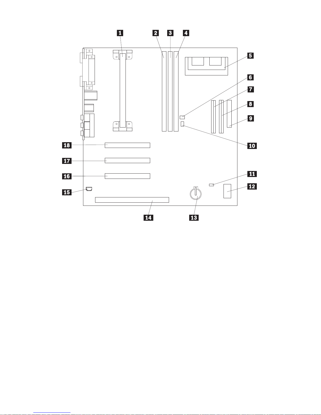
.1/ Microprocessor
.2/ DIMM 0
.3/ DIMM 1
.4/ DIMM 2 (in some models)
.5/ Video memory upgrade
connector (in some models)
.6/ Wake on LAN connector
.7/ Primary EIDE connector
.8/ Secondary EIDE connector
.9/ Diskette connector
.1ð/ Wake on Ring connector
.11/ CMOS clear jumper
.12/ Rocker switches
.13/ Battery
.14/ ISA adapter slot
.15/ Audio connector for CD-ROM
.16/ PCI adapter slot 3
.17/ PCI adapter slot 2
.18/ PCI adapter slot 1
Chapter 7. Installing Options 63
Page 78

Working with System Memory
You can add memory to your computer to increase system performance.
Your computer has either two or three connectors (depending on the
model) for installing memory modules that provide up to a maximum of
256 MB or 384 MB (depending on the model).
Your computer uses dual inline memory modules (DIMMs). The
IBM-installed DIMMs that come with your computer are unbuffered,
synchronous dynamic random access memory (SDRAM).
When installing or replacing DIMMs, the following rules apply:
Fill each system memory connector sequentially, starting at DIMM 0.
Use only 3.3 V, 100 MHz, unbuffered, SDRAM DIMMs
Use only 16, 32, 64, or 128 MB DIMMs in any combination of
supported SDRAM DIMMs.
Note: To locate the memory connectors on the system board, see
“Identifying Parts on the System Board” on page 62.
Installing and Removing a DIMM
Before you begin:
Read “Safety Information” on page vii and “Handling
Static-Sensitive Devices” on page 54.
Read the instructions that come with the new system memory.
Turn off the computer and all other connected devices.
Disconnect all cables attached to the computer and remove the
computer cover (see “Removing the Cover” on page 56).
Read “Accessing the System Board” on page 62 to learn the
location of the parts on the system board.
64 PC 300GL User Guide
Page 79

To Install a DIMM:
1. You may need to remove the power supply to gain access to the DIMM
sockets. See “Moving the Power Supply” on page 59.
2. If you are replacing a DIMM that is already installed, press the
retaining clips down and lift the DIMM out of the socket.
3. If the retaining clips are not already open, open them.
Chapter 7. Installing Options 65
Page 80

4. Install the DIMM straight down into the connector until the retaining
clips close.
Notches
5. Reinstall the power supply if you removed it.
What to do next:
To work with another option, go to the appropriate section.
To complete the installation, go to “Completing the Installation” on
page 79.
66 PC 300GL User Guide
Page 81

Working with Video Memory
This section provides information and instructions for installing and
removing video memory from the video memory connector on the system
board of some models.
For some models, you can add video memory to your computer to increase
the video performance, resolution, and graphics capabilities. Some models
have a connector for installing a memory module that provides up to a
maximum of 4 MB of video memory. Models without the connector
already have 4 MB of video memory.
Installing a Video Memory Module
Before you begin:
Read “Safety Information” on page vii and “Handling
Static-Sensitive Devices” on page 54.
Read the instructions that come with the new video memory.
Turn off the computer and all other connected devices.
Disconnect all cables attached to the computer and remove the
computer cover (see “Removing the Cover” on page 56).
Read “Accessing the System Board” on page 62 to learn the
location of parts on the system board.
To install a video memory module:
1. Note the position of the power supply so that it can be reinstalled later.
Move the power supply aside to gain access to the video memory
socket. See “Moving the Power Supply” on page 59.
2. Install the video memory module into the connector at a 45 degree
angle and then push it down until it snaps into place.
3. Reinstall the power supply. See “Moving the Power Supply” on
page 59.
What to do next:
To work with another option, go to the appropriate section.
To complete the installation, go to “Completing the Installation” on
page 79.
Chapter 7. Installing Options 67
Page 82

Working with Adapters
This section provides information and instructions for installing and
removing adapters.
When installing or removing adapters, you must resolve any resource
conflicts that are created as a result. For example, if you install an ISA
legacy adapter, you might need to manually configure the adapter by
setting a variety of switches on the adapter and by using the
Configuration/Setup Utility Program program. For more information on
using the Configuration/Setup Utility Program to configure adapters, see
“Legacy Adapters” on page 70.
Adapter Types
Many adapters now use Plug and Play technology that enables the computer
to automatically configure the adapter, provided that the required resources
are available. Refer to the instructions that come with your adapter to
determine if it is Plug and Play. For more information, see “Adapter
Configuration” on page 69.
Adapter Slots
Your computer system board has expansion slots used to connect adapters
to the industry standard architecture (ISA) and peripheral component
interconnect (PCI) buses. Slots 1 through 3 are designed for PCI adapters.
Slot 4 is an ISA slot. You can install an adapter up to 228 mm (9 inches)
long in your computer.
Installing Adapters
Before you begin:
Read “Safety Information” on page vii and “Handling
Static-Sensitive Devices” on page 54.
Read the instructions that come with the new adapter.
Turn off the computer and all other connected devices.
Disconnect all cables attached to the computer and remove the
computer cover (see “Removing the Cover” on page 56).
To install an adapter in a PCI or ISA expansion slot:
1. Review the instructions that come with the adapter to determine if it
must be installed in an ISA or PCI expansion slot.
68 PC 300GL User Guide
Page 83

2. Move the power supply aside if necessary. See “Moving the Power
Supply” on page 59.
3. Remove the screw and slot cover for the appropriate expansion slot.
4. Remove the adapter from its static-protective package.
5. Install the adapter into the appropriate slot on the system board.
6. Install the screw that secures the adapter.
Note: If you are installing a wake on LAN supported network
adapter, attach the wake on LAN cable that came with the
adapter to the wake on LAN connector on the system board.
For the location of this connector, see the diagram of the system
board on the inside of your computer.
7. If you moved the power supply aside, replace it. See “Moving the
Power Supply” on page 59.
8. Replace the cover and continue with adapter configuration.
Adapter Configuration
Along with the documentation that comes with your adapter, use the
following information to help with adapter configuration.
Chapter 7. Installing Options 69
Page 84

Plug and Play Adapters
Plug and Play is a configuration method that makes expanding your
computer easier. Support for Plug and Play is built into the system board
of your computer.
A Plug and Play adapter has no switches or jumpers that must be set. A
Plug and Play adapter comes with configuration specifications set in
memory. These specifications provide installation information to the
computer during startup. When you install or remove Plug and Play
adapters, this information is interpreted by the basic input/output system
(BIOS), which supports Plug and Play technology. If the required resources
are available, the BIOS software automatically configures the adapter using
resources not already used by other devices.
Adapters designed for PCI slots are Plug and Play devices. Most ISA
adapters are not Plug and Play and are referred to as legacy adapters. See
“Legacy Adapters.”
Note: See Chapter 8, “Troubleshooting” on page 85 for information on
error messages resulting from resource conflicts.
Legacy Adapters
Adapters that are not Plug and Play are known as legacy adapters. If you
install a legacy adapter, you must manually configure it by setting switches
or jumpers on the adapter and by reserving its resources using the
Configuration/Setup Utility Program.
In the Configuration/Setup Utility Program, the ISA Legacy Resources
screen shows the computer resources that are typically required by
adapters:
Memory resources
I/O port resources
DMA resources
Interrupt resources
See “ISA Legacy Resources” on page 39 for instructions to use the
Configuration/Setup Utility Program to configure legacy adapters to work
in your computer.
What to do next:
To work with another option, go to the appropriate section.
To complete the installation, go to “Completing the Installation” on
page 79.
70 PC 300GL User Guide
Page 85

Working with Internal Drives
This section provides information and instructions for installing and
removing internal drives.
When you install an internal drive, it is important to note what type and
size of drive you can install in each bay. Also, it is important to correctly
connect the internal drive cables to the installed drive.
Internal Drives
Internal drives are devices that your computer uses to read and store data.
You can add drives to your computer to increase storage capacity and to
enable your computer to read other types of media. Some of the different
drives available for your computer are:
Diskette drives
Hard disk drives
Tape drives
CD-ROM drives
Zip drives and other removable media drives
Internal drives are installed in bays. Within this book, the bays are referred
to as bay 1, bay 2, and so on.
Your computer comes with the following IBM-installed drives:
A CD-ROM drive in bay 1 (some models).
A Zip drive in bay 2 (some models).
A 3.5-inch diskette drive in bay 3.
A 3.5-inch hard disk drive in bay 4.
Models that do not have drives installed in bays 1 and 2 have a static shield
and bay panel installed.
Chapter 7. Installing Options 71
Page 86

Bay 1 (5.25 inch drive)
Bay 2 (3.5 inch drive)
Bay 3 (3.5 inch floppy drive)
Bay 4 (hard disk drive)
Drive Specifications
The following table describes some of the drives you can install in each bay
and their height requirements.
Bay 1 - Max Height: 41.3mm (1.6 in.) CD-ROM drive
5.25-inch tape backup
drive
5.25-inch hard disk drive
Bay 2 - Max Height: 41.3mm (1.6 in.) 3.5-inch tape backup drive
3.5-inch hard disk drive
Bay 3 - Max Height: 25.4mm (1.0 in.) 3.5-inch diskette drive
Bay 4 - Max Height: 25.4mm (1.0 in.) 3.5-inch hard disk drive
Notes:
1. Drives that are greater than 41.3 mm (1.6 in.) high cannot be installed.
2. Install removable media (diskettes, tapes, or CDs) drives in the
accessible bays: bays 1 or 2.
72 PC 300GL User Guide
Page 87

Power and Signal Cables for Internal Drives
Your computer uses cables to connect integrated drive electronics (IDE)
drives to the power supply and system board. The following cables are
provided:
Four-wire power cables connect most drives to the power supply. At the
end of these cables are plastic connectors that attach to different drives;
these connectors vary in size. Also, certain power cables attach to the
system board.
Flat signal cables for connecting IDE and diskette drives to the system
board; signal cables are sometimes called ribbon cables. There are two
sizes of ribbon signal cables that come with your computer:
– The wider signal cable has two or three connectors.
- If the cable has three connectors, one of these connectors is
attached to the drive, one is a spare, and the third attaches to
the secondary IDE connector on the system board.
- If the cable has two connectors, one of these connectors is
attached to the hard disk drive, and the other attaches to the
primary IDE connector on the system board.
Note: If you want to add another device, and the signal cable
has only two connectors, you will need a signal cable
with three connectors.
– The narrower signal cable has two connectors for attaching the
diskette drive to the diskette-drive connector on the system board.
Note: To locate connectors on the system board, see “Identifying Parts on
the System Board” on page 62.
The following are some important points to remember when connecting
power and signal cables to internal drives:
The drives that are preinstalled in your computer come with power and
signal cables attached. If you replace any drives, it is important to
remember which cable is attached to which drive.
When you install a drive, ensure that the drive connector at the end of
the signal cable is always connected to a drive; also, ensure that the
drive connector at the other end is connected to the system board. This
reduces electronic noise from the computer.
If two IDE devices are used on a single cable, one must be designated
as the primary or master device and the other as the secondary or
subordinate device; otherwise, some of the IDE devices might not be
recognized by the system. The primary or secondary designation is
determined by switch or jumper settings on each IDE device.
Chapter 7. Installing Options 73
Page 88

If two devices are on a single cable, and only one is a hard disk drive,
the hard disk drive must be set as the master device.
If you have only one device on a cable, it must be set as master.
For help in selecting drives, cables, and other options for your computer, do
one of the following:
Within the United States, call 1-800-IBM-2YOU (1-800-426-2968), your
IBM reseller, or your IBM marketing representative.
Within Canada, call 1-800-565-3344 or 1-800-465-7999.
Outside the United States and Canada, contact your IBM reseller or
IBM marketing representative.
Installing Internal Drives
Before you begin:
Read “Safety Information” on page vii and “Handling
Static-Sensitive Devices” on page 54.
Turn off the computer and all other connected devices.
Disconnect all external cables and power cords, and then remove
the computer cover (see “Removing the Cover” on page 56).
74 PC 300GL User Guide
Page 89

To install an internal drive:
1. Place a medium flat–head screwdriver into the notch on the right side
of the bay panel covering the bay where you want to install the drive
and twist the screwdriver to pop the bay panel out of the bay.
2. Insert a flat–head screwdriver into one of the slots on the static shield
and pry the static shield loose from the drive bay.
3. Inside the computer are one or two picture frame panels for use when
you have installed a drive into one of the bays. The picture frame
panel for the 3.5-inch drive bay is attached to the outside of the chassis.
Chapter 7. Installing Options 75
Page 90

The picture frame panel for the 5.25-inch drive bay is attached to the
inside of the chassis. Remove the picture frame panel that was packed
on the inside of the chassis to make room for installing the drive.
4. Install the drive into the bay. Align the screw holes and insert the two
screws.
5. If the drive you installed has nonremovable media (such as a hard disk
drive), replace the bay panel.
If the drive you installed is a removable media drive (such as a Zip
drive), place the picture frame that came with your computer over the
drive bay.
6. Connect the power and signal cables to the drive.
76 PC 300GL User Guide
Page 91

What to do next:
To work with another option, go to the appropriate section.
To complete the installation, go to “Completing the Installation” on
page 79.
Installing a Security U-bolt
To help prevent hardware theft you can use the cover lock and add a
security U-bolt and cable to your computer. After you add the security
cable, make sure that it does not interfere with other cables that are
connected to the computer.
Before you begin:
Obtain the following:
– A 19-mm (3/4 in.) U-bolt and threaded nuts that fit the U-bolt
– A security cable
– A lock, such as a combination lock or padlock
– An appropriately sized or adjustable wrench
– A small, flat-blade screwdriver
Read “Safety Information” on page vii and “Handling
Static-Sensitive Devices” on page 54.
Turn off the computer and all other connected devices.
Disconnect all external cables and power cords, and remove the
computer cover (see “Removing the Cover” on page 56).
Chapter 7. Installing Options 77
Page 92

To install a U-bolt:
1. Use a tool, such as a screwdriver, to remove the two metal knockouts.
Metal
Knockouts
2. Insert the U-bolt .1/ through the rear panel .2/; then attach and
tighten the nuts .3/ with an appropriately sized or adjustable wrench.
3. Replace the computer cover. For more information, see “Replacing the
Cover and Connecting the Cables” on page 79.
4. Thread the cable through the U-bolt and around an object that is not a
part of or permanently secured to the building structure or foundation,
and from which it cannot be removed; then fasten the cable ends
together with a lock.
The following illustration shows an example of how this might work.
78 PC 300GL User Guide
Page 93

Completing the Installation
After working with options, you need to install any removed parts, replace
the cover, and reconnect any cables, including power cords and telephone
lines. Also, depending on the option installed, you might need to update
information in the Configuration/Setup Utility Program program.
The following list is a quick reference to these procedures:
“Replacing the Cover and Connecting the Cables”
“Updating the Computer Configuration” on page 81
Replacing the Cover and Connecting the Cables
To replace the cover and connect cables to your computer:
1. Ensure that all components have been reassembled correctly and that
no tools or loose screws are left inside your computer.
2. Clear any cables that might impede the replacement of the cover.
3. Position the cover over the chassis so that the front edge is
approximately one inch away from the front bezel.
Chapter 7. Installing Options 79
Page 94

There are several rail guides at the bottom of the cover. To install the
cover properly, these rail guides must engage the metal rails at the
bottom of the chassis.
4. Lower the cover down over the chassis so that the rail guides engage
the rails.
5. Slide the cover forward.
You might need to lift the front of the cover slightly to align it
properly.
6. Insert the three thumbscrews into the holes in the cover and the chassis
and tighten.
7. Reconnect the external cables and cords to the computer. See
“Connecting Computer Cables” on page 10.
Important Information:
When the power cord is first plugged in, the computer might
appear to power on for a few seconds, then power off. This is a
normal sequence to enable the computer to self–initialize.
80 PC 300GL User Guide
Page 95

Important:
If you are in the U.K., plug in the power cords first and then connect
the telephone line to the wall outlet and the computer. If you have a
modem or fax machine attached to the computer, and you are not in the
U.K., reconnect the telephone line to the wall outlet and the computer
and then plug the power cords into properly grounded electrical outlets.
Updating the Computer Configuration
Important:
The configuration information in this section applies to installing
options. For more information on using the Configuration/Setup Utility
Program, see the Chapter 5, “Using the Configuration/Setup Utility
Program” on page 29.
You might need to install device drivers after updating the configuration
settings. For more information, see the instructions that come with the
option to determine if device drivers are required and how to install them.
Device drivers are included on the Software Selections CD that comes with
your computer.
After adding, removing, or replacing options, the configuration settings
must be updated. This reconfiguration is performed automatically by the
computer or manually by you. When the computer automatically configures
an option, it uses system programs. However, you must save the new
settings. If the system programs do not update the settings, you can use
the Configuration/Setup Utility Program program to reconfigure the
appropriate settings.
For example, when you start your computer after adding most internal hard
disk drives, the settings might be updated. If the settings are not updated,
use the Configuration/Setup Utility Program to make and save those
changes. However, if a resource conflict arises after an ISA legacy adapter
is installed or removed, you must manually update the computer
configuration and save the information. For instructions, see “ISA Legacy
Resources” on page 39.
Note: For more information on error messages from resource conflicts, see
Chapter 8, “Troubleshooting” on page 85.
Chapter 7. Installing Options 81
Page 96

Starting the Configuration/Setup Utility Program
When you restart the computer for the first time after working with most
options, a message may appear indicating that a configuration change has
occurred. If such a message appears, you are then prompted to enter the
Configuration/Setup Utility Program program to manually update the
configuration settings or to confirm and save the settings that were
automatically updated by the system programs.
After you change an option and restart the computer, the following screen
might appear.
à ð
POST Startup Error(s)
The following error(s) were detected when the system was
started:
162 Configuration Change Has Occurred
Select one of the following:
Continue
Exit Setup
á
ñ
Note: Depending on the configuration changes that occurred, the error
message you see might be different from the one shown here. If the
preceding screen appears, select Continue until you reach the
Configuration/Setup Utility Program menu (see Chapter 5, “Using
the Configuration/Setup Utility Program” on page 29).
If the preceding screen does not appear, then see Chapter 5, “Using the
Configuration/Setup Utility Program” on page 29.
82 PC 300GL User Guide
Page 97

Configuring an ISA Legacy Adapter
To configure an installed ISA legacy adapter, you might need to alter switch
or jumper settings on the adapter. Also, you must use the
Configuration/Setup Utility Program program to identify the ISA legacy
resource requirements, such as memory locations, I/O assignments, and
DMA and interrupt assignments.
Note: For more information about required resources and switch settings,
refer to the documentation that comes with the adapter.
If you remove an ISA legacy adapter, you must set to Available the system
resources that are no longer being used. To do this, follow the procedures
in Chapter 5, “Using the Configuration/Setup Utility Program” on page 29
and select Available at step 4.
Note: For more information on adapters and resolving conflicts, see
“Adapter Configuration” on page 69 and “Interrupt and DMA
Resources” on page 40.
For more detailed instructions on configuring ISA legacy adapters, see “ISA
Legacy Resources” on page 39.
Configuring Startup Devices
When your computer is turned on, it looks for an operating system. The
order in which it searches devices for the operating system is the startup
sequence. After adding new devices to the computer, you might want to
change the startup sequence. You can use the Configuration/Setup Utility
Program program to configure startup devices. See “Setting the Startup
Sequence” on page 38.
Chapter 7. Installing Options 83
Page 98

84 PC 300GL User Guide
Page 99

Chapter 8. Troubleshooting
This chapter describes diagnostic tools that are available to you. You can
use these tools to identify and correct problems that might come up as you
use your computer. This chapter also contains information about option
diskettes and how to recover from a BIOS update failure.
Note: If your computer does not start when you press the power switch,
do the following:
Make sure all cables are securely connected to the correct
locations.
Make sure the computer cover is installed properly (pushed all
the way on).
If this does not correct the problem, have the computer serviced.
Using Diagnostic Tools
Computer problems can be caused by hardware, software, or user error (for
example, pressing the wrong key). You can use the diagnostic aids
discussed in this chapter to help you solve such problems yourself or gather
helpful information you can pass on to a service technician.
You can check the hardware by following the procedures in this chapter.
You can also use the diagnostic programs provided with your computer
(see “IBM Enhanced Diagnostics” on page 118 for a description of these
programs).
If the hardware checks out, and you have not made a user error, you might
have a software problem. If you suspect that you have a software problem
and your computer came with IBM-preinstalled software, see the About
Your Software publication and the operating system documentation supplied
with your computer. If you have installed software applications yourself,
see the documentation supplied with the software.
The following tools are available to diagnose hardware-related problems:
Error messages
Power-on self-test (POST)
Troubleshooting charts
Diagnostic programs
Copyright IBM Corp. 1998 85
Page 100

Power-On Self-Test (POST)
Each time you turn on your computer, it performs a series of tests that
check the operation of the base computer. This series of tests is called the
power-on self-test (POST).
POST does the following:
Checks basic system-board operations
Checks the memory operation
Compares the current system configuration with that established by the
Configuration/Setup Utility Program
Starts the video operation
Verifies that the diskette drives are working
Verifies that the hard disk drive and the CD-ROM drive are working
If Power-On Self-Test is set to [Enhanced], numbers showing the amount of
memory being tested appear in the top-left corner of the screen until the
total amount of memory in the system is reached. Options for running a
quick POST or accessing the Configuration/Setup Utility Program appear in
the lower-left corner of the screen. Quick mode is the default mode of
operation.
Note: The amount of available memory shown might be somewhat less
than expected because of basic input/output system (BIOS)
shadowing in random access memory (RAM).
If POST finishes without detecting any problems, the first screen of your
operating system or application program appears if you have not set a
power-on password. If you have set a power-on password, a password
prompt appears. You must enter your password before the first screen of
your operating system or application program will appear. (For more
information on using passwords, see “Power-On Password” on page 32.)
If Power On Status is Enabled and POST detects a problem, you will hear
multiple beeps or no beep. In most cases, an error code appears in the top
left corner of the screen, and in some cases a description of the error is
displayed beside the code. (Note that the screen will sometimes display
multiple error codes and descriptions.) For more information about what
caused an error message to appear and what action to take, see “Solving
POST Error Message Problems” on page 88 and “POST Message Charts” on
page 90.
If you hear no beep at all during POST, see “Troubleshooting Charts” on
page 107. You might need to have your computer serviced.
86 PC 300GL User Guide
 Loading...