

Page 1

IBM IntelliStation M Pro
Ty pes 6225 and 6228
User’ s Guid e
Page 2

Page 3

IBM IntelliStation M Pro
Ty pes 6225 and 6228
User’ s Guid e
Page 4

©
US
Note:
Before using this information and the product it supports, read the information in Appendix B, “IBM Statement of Limited Warranty
Z125-4753-08 04/2004,” on page 91 and Appendix C, “Notices,” on page 109.
First Edition (December 2004)
Copyright International Business Machines Corporation 2004. All rights reserved.
Government Users Restricted Rights – Use, duplication or disclosure restricted by GSA ADP Schedule Contract
with IBM Corp.
Page 5

©
Contents
Safety . . . . . . . . . . . . . . . . . . . . . . . . . . . . vii
Chapter 1. Introducing the IntelliStation M Pro computer . . . . . . . .1
Related documentation . . . . . . . . . . . . . . . . . . . . . .1
Notices and statements used in this document . . . . . . . . . . . . . .2
Features and specifications . . . . . . . . . . . . . . . . . . . . .3
What your computer offers . . . . . . . . . . . . . . . . . . . . .4
Software . . . . . . . . . . . . . . . . . . . . . . . . . . . .4
Preinstalled software . . . . . . . . . . . . . . . . . . . . . .5
Software on CD . . . . . . . . . . . . . . . . . . . . . . . .6
Software available on the World Wide Web . . . . . . . . . . . . . .6
Reliability, availability, and serviceability features . . . . . . . . . . . . .7
Chapter 2. Operating the computer . . . . . . . . . . . . . . . . .9
Controls and LEDs . . . . . . . . . . . . . . . . . . . . . . . .9
Turning on the computer . . . . . . . . . . . . . . . . . . . . .10
Using preinstalled software . . . . . . . . . . . . . . . . . . . .12
Running the operating-system setup program . . . . . . . . . . . .12
Installing other operating systems . . . . . . . . . . . . . . . . .12
Viewing the license agreement . . . . . . . . . . . . . . . . . .13
Registering your computer . . . . . . . . . . . . . . . . . . . .13
Creating an emergency recovery-repair diskette in Windows . . . . . . .13
Creating an IBM Enhanced Diagnostics diskette in Windows . . . . . . .14
Using video features . . . . . . . . . . . . . . . . . . . . . . .15
Video device drivers . . . . . . . . . . . . . . . . . . . . . .15
Changing monitor settings . . . . . . . . . . . . . . . . . . . .15
Using audio features . . . . . . . . . . . . . . . . . . . . . . .16
Using security features . . . . . . . . . . . . . . . . . . . . . .16
Anti-intrusion features . . . . . . . . . . . . . . . . . . . . .16
Component protection . . . . . . . . . . . . . . . . . . . . .16
Data protection . . . . . . . . . . . . . . . . . . . . . . . .17
Locking the keyboard . . . . . . . . . . . . . . . . . . . . .17
Updating system programs . . . . . . . . . . . . . . . . . . . .17
Managing your computer . . . . . . . . . . . . . . . . . . . . .18
Shutting down the operating system . . . . . . . . . . . . . . . . .19
Turning off the computer . . . . . . . . . . . . . . . . . . . . .19
Chapter 3. Configuring the computer . . . . . . . . . . . . . . . .21
Using the Configuration/Setup Utility program . . . . . . . . . . . . .22
Starting the Configuration/Setup Utility program . . . . . . . . . . . .22
Configuration/Setup Utility menu choices . . . . . . . . . . . . . .22
Using passwords . . . . . . . . . . . . . . . . . . . . . . .25
Using the Boot Menu program . . . . . . . . . . . . . . . . . . .25
Enabling the Broadcom NetXtreme Gigabit Ethernet Boot Agent . . . . . . .26
Configuring the Gigabit Ethernet controller . . . . . . . . . . . . . . .26
Using the SCSISelect Utility program (some models) . . . . . . . . . . .26
Starting the SCSISelect Utility program . . . . . . . . . . . . . . .26
SCSISelect menu choices . . . . . . . . . . . . . . . . . . . .27
Chapter 4. Installing options . . . . . . . . . . . . . . . . . . .29
Installation guidelines . . . . . . . . . . . . . . . . . . . . . .29
System reliability considerations . . . . . . . . . . . . . . . . .29
Handling static-sensitive devices . . . . . . . . . . . . . . . . .29
Copyright IBM Corp. 2004
iii
Page 6

iv
Installing options in your computer . . . . . . . . . . . . . . . . . .30
Major components of your computer . . . . . . . . . . . . . . . .30
System-board option connectors . . . . . . . . . . . . . . . . .31
System-board internal connectors . . . . . . . . . . . . . . . . .32
System-board external connectors . . . . . . . . . . . . . . . . .33
Removing the side cover . . . . . . . . . . . . . . . . . . . .34
Removing the bezel . . . . . . . . . . . . . . . . . . . . . .34
Installing an adapter . . . . . . . . . . . . . . . . . . . . . .35
Cabling an optional SCSI adapter . . . . . . . . . . . . . . . . .38
Installing a drive . . . . . . . . . . . . . . . . . . . . . . .39
Installing memory modules . . . . . . . . . . . . . . . . . . .46
Installing a security cable . . . . . . . . . . . . . . . . . . . .48
Replacing the bezel . . . . . . . . . . . . . . . . . . . . . .48
Replacing the side cover . . . . . . . . . . . . . . . . . . . .49
Connecting external options . . . . . . . . . . . . . . . . . . . .49
Input/output connectors . . . . . . . . . . . . . . . . . . . . . .50
Audio connectors . . . . . . . . . . . . . . . . . . . . . . .51
Auxiliary-device (pointing-device) connector . . . . . . . . . . . . .51
Ethernet (RJ-45) connector . . . . . . . . . . . . . . . . . . .51
IEEE 1394 (FireWire) connector (some models) . . . . . . . . . . . .52
Keyboard connector . . . . . . . . . . . . . . . . . . . . . .52
Parallel connector . . . . . . . . . . . . . . . . . . . . . . .52
Serial connectors . . . . . . . . . . . . . . . . . . . . . . .53
Ultra320 SCSI connector . . . . . . . . . . . . . . . . . . . .53
Universal Serial Bus connectors . . . . . . . . . . . . . . . . .54
Video connector . . . . . . . . . . . . . . . . . . . . . . .54
Chapter 5. Solving problems . . . . . . . . . . . . . . . . . . .57
Diagnostic tools overview . . . . . . . . . . . . . . . . . . . . .57
Power-on self-test (POST) . . . . . . . . . . . . . . . . . . . . .59
POST beep codes . . . . . . . . . . . . . . . . . . . . . .59
POST error messages . . . . . . . . . . . . . . . . . . . . .61
Diagnostic programs and error messages . . . . . . . . . . . . . . .65
Text messages . . . . . . . . . . . . . . . . . . . . . . . .66
Starting the diagnostic programs and viewing the test log . . . . . . . .67
Diagnostic error message tables . . . . . . . . . . . . . . . . .68
Small computer system interface (SCSI) messages . . . . . . . . . . .72
PC-Doctor for Windows . . . . . . . . . . . . . . . . . . . . . .73
Troubleshooting charts . . . . . . . . . . . . . . . . . . . . . .73
CD-ROM drive problems . . . . . . . . . . . . . . . . . . . .74
Diskette drive problems . . . . . . . . . . . . . . . . . . . . .74
General problems . . . . . . . . . . . . . . . . . . . . . . .74
Hard disk drive problems . . . . . . . . . . . . . . . . . . . .74
Intermittent problems . . . . . . . . . . . . . . . . . . . . . .75
Keyboard, mouse, or pointing-device problems . . . . . . . . . . . .75
Memory problems . . . . . . . . . . . . . . . . . . . . . . .76
Microprocessor problems . . . . . . . . . . . . . . . . . . . .76
Monitor problems . . . . . . . . . . . . . . . . . . . . . . .76
Option problems . . . . . . . . . . . . . . . . . . . . . . .77
Parallel port problems . . . . . . . . . . . . . . . . . . . . .78
Power problems . . . . . . . . . . . . . . . . . . . . . . .78
Printer problems . . . . . . . . . . . . . . . . . . . . . . .78
Serial port problems . . . . . . . . . . . . . . . . . . . . . .79
Software problems . . . . . . . . . . . . . . . . . . . . . .79
Universal Serial Bus (USB) port problems . . . . . . . . . . . . . .79
System-board error LEDs . . . . . . . . . . . . . . . . . . . .79
IBM IntelliStation M Pro Types 6225 and 6228: User’s Guide
Page 7

91
Software error messages . . . . . . . . . . . . . . . . . . . .80
Troubleshooting the Ethernet controller . . . . . . . . . . . . . . .81
Recovering your operating system and preinstalled software . . . . . . . .81
Recovering the operating system . . . . . . . . . . . . . . . . .81
Recovering or installing device drivers . . . . . . . . . . . . . . .82
Creating and using an IBM Enhanced Diagnostics diskette in Windows . . . .82
Creating an IBM Enhanced Diagnostics diskette . . . . . . . . . . . .82
Using the IBM Enhanced Diagnostics diskette . . . . . . . . . . . .83
Using the recovery-repair diskette in Windows . . . . . . . . . . . . .83
Updating (flash-updating) the BIOS code on your computer . . . . . . . .84
Recovering from a POST/BIOS update failure . . . . . . . . . . . . .84
Erasing a lost or forgotten password (clearing CMOS) . . . . . . . . . .85
Clearing hardware option conflicts and saving option ROM space . . . . . .86
Replacing the battery . . . . . . . . . . . . . . . . . . . . . .87
Appendix A. Getting help and technical assistance . . . . . . . . . .89
Before you call . . . . . . . . . . . . . . . . . . . . . . . . .89
Using the documentation . . . . . . . . . . . . . . . . . . . . .89
Getting help and information from the World Wide Web . . . . . . . . . .90
Software service and support . . . . . . . . . . . . . . . . . . .90
Hardware service and support . . . . . . . . . . . . . . . . . . .90
Appendix B. IBM Statement of Limited Warranty Z125-4753-08 04/2004
Part 1 - General Terms . . . . . . . . . . . . . . . . . . . . . .91
Part 2 - Country-unique Terms . . . . . . . . . . . . . . . . . . .94
Part 3 - Warranty Information . . . . . . . . . . . . . . . . . . . 106
Appendix C. Notices . . . . . . . . . . . . . . . . . . . . . . 109
Edition notice . . . . . . . . . . . . . . . . . . . . . . . . . 109
Trademarks . . . . . . . . . . . . . . . . . . . . . . . . . .110
Important notes . . . . . . . . . . . . . . . . . . . . . . . .110
Product recycling and disposal . . . . . . . . . . . . . . . . . . . 111
Battery return program . . . . . . . . . . . . . . . . . . . . . . 111
Electronic emission notices . . . . . . . . . . . . . . . . . . . .112
Federal Communications Commission (FCC) statement . . . . . . . .112
Industry Canada Class B emission compliance statement . . . . . . . .113
Avis de conformité à la réglementation d’Industrie Canada . . . . . . .113
European Union EMC Directive conformance statement . . . . . . . .113
Japanese Voluntary Control Council for Interference (VCCI) statement
113
Power cords . . . . . . . . . . . . . . . . . . . . . . . . .113
Index . . . . . . . . . . . . . . . . . . . . . . . . . . . .117
Contents
v
Page 8

vi
IBM IntelliStation M Pro Types 6225 and 6228: User’s Guide
Page 9

©
Safety
Before installing this product, read the Safety Information.
Antes de instalar este produto, leia as Informações de Segurança.
Pred instalací tohoto produktu si prectete prírucku bezpecnostních instrukcí.
Læs sikkerhedsforskrifterne, før du installerer dette produkt.
Lees voordat u dit product installeert eerst de veiligheidsvoorschriften.
Ennen kuin asennat tämän tuotteen, lue turvaohjeet kohdasta Safety Information.
Avant d’installer ce produit, lisez les consignes de sécurité.
Vor der Installation dieses Produkts die Sicherheitshinweise lesen.
Prima di installare questo prodotto, leggere le Informazioni sulla Sicurezza.
Les sikkerhetsinformasjonen (Safety Information) før du installerer dette produktet.
Antes de instalar este produto, leia as Informações sobre Segurança.
Antes de instalar este producto, lea la información de seguridad.
Läs säkerhetsinformationen innan du installerar den här produkten.
Copyright IBM Corp. 2004
vii
Page 10

To
v Do
v
v
v
v
v
v
To
To
1.
2.
3.
4.
5.
1.
2.
3.
4.
Statement 1:
DANGER
Electrical
current from power, telephone, and communication cables is
hazardous.
avoid a shock hazard:
not connect or disconnect any cables or perform installation,
maintenance, or reconfiguration of this product during an electrical
storm.
Connect all power cords to a properly wired and grounded electrical
outlet.
Connect to properly wired outlets any equipment that will be attached to
this product.
When possible, use one hand only to connect or disconnect signal
cables.
Never turn on any equipment when there is evidence of fire, water, or
structural damage.
Disconnect the attached power cords, telecommunications systems,
networks, and modems before you open the device covers, unless
instructed otherwise in the installation and configuration procedures.
Connect and disconnect cables as described in the following table when
installing, moving, or opening covers on this product or attached
devices.
Connect:
Turn everything OFF.
First, attach all cables to devices.
Attach signal cables to connectors.
Attach power cords to outlet.
Turn device ON.
Disconnect:
Turn everything OFF.
First, remove power cords from outlet.
Remove signal cables from connectors.
Remove all cables from devices.
viii
IBM IntelliStation M Pro Types 6225 and 6228: User’s Guide
Page 11

a
Do
v
v
v
of
v Do
v
Statement 2:
CAUTION:
When replacing the lithium battery, use only IBM Part Number 33F8354 or an
equivalent type battery recommended by the manufacturer. If your system has
module containing a lithium battery, replace it only with the same module
type made by the same manufacturer. The battery contains lithium and can
explode if not properly used, handled, or disposed of.
not:
Throw or immerse into water
Heat to more than 100°C (212°F)
Repair or disassemble
Dispose
the battery as required by local ordinances or regulations.
Statement 3:
CAUTION:
When laser products (such as CD-ROMs, DVD drives, fiber optic devices, or
transmitters) are installed, note the following:
not remove the covers. Removing the covers of the laser product could
result in exposure to hazardous laser radiation. There are no serviceable
parts inside the device.
Use of controls or adjustments or performance of procedures other than
those specified herein might result in hazardous radiation exposure.
DANGER
Some
laser products contain an embedded Class 3A or Class 3B laser
diode. Note the following.
Laser radiation when open. Do not stare into the beam, do not view directly
with optical instruments, and avoid direct exposure to the beam.
Safety
ix
Page 12
≥ 18 kg
≥ 32 kg
≥ 55 kg
x
Statement 4:
(39.7 lb)
(70.5 lb)
(121.2 lb)
CAUTION:
Use safe practices when lifting.
Statement 5:
CAUTION:
The power control button on the device and the power switch on the power
supply do not turn off the electrical current supplied to the device. The device
also might have more than one power cord. To remove all electrical current
from the device, ensure that all power cords are disconnected from the power
source.
1 2
IBM IntelliStation M Pro Types 6225 and 6228: User’s Guide
Page 13
a
Be
Statement 8:
CAUTION:
Never remove the cover on a power supply or any part that has the following
label attached.
Hazardous voltage, current, and energy levels are present inside any
component that has this label attached. There are no serviceable parts inside
these components. If you suspect a problem with one of these parts, contact
service technician.
WARNING: Handling the cord on this product or cords associated with accessories
sold with this product, will expose you to lead, a chemical known to the State of
California to cause cancer, and birth defects or other reproductive harm. Wash
hands after handling.
ADVERTENCIA: El contacto con el cable de este producto o con cables de
accesorios que se venden junto con este producto, pueden exponerle al plomo, un
elemento químico que en el estado de California de los Estados Unidos está
considerado como un causante de cancer y de defectos congénitos, además de
otros riesgos reproductivos. Lávese las manos después de usar el producto.
Important:
All caution and danger statements in this documentation begin with a
number. This number is used to cross reference an English caution or
danger statement with translated versions of the caution or danger
statement in the IBM Safety Information document.
For example, if a caution statement begins with a number 1,
translations for that caution statement appear in the IBM Safety
Information document under statement 1.
sure to read all caution and danger statements in this
documentation before performing the instructions. Read any additional
safety information that comes with your server or optional device before
you install the device.
Safety
xi
Page 14

xii
IBM IntelliStation M Pro Types 6225 and 6228: User’s Guide
Page 15

M
on
v
v
©
Chapter 1. Introducing the IntelliStation M Pro computer
The IBM
®
IntelliStation
®
Pro Types 6225 and 6228 incorporate many of the latest
advances in computing technology and can be expanded and upgraded as your
needs change.
You can obtain up-to-date information about your computer and other IBM computer
products at http://www.ibm.com/pc/intellistation/.
The computer model and serial numbers for the M Pro Types 6225 and 6228 are
labels on the bottom of the computer and on the lower-right side of the bezel.
You will need these numbers to register your computer with IBM.
Note: The illustrations in this document might differ slightly from your hardware.
Model number
and serial number
Related documentation
This User’s Guide provides general information about your computer, including
information about features, how to configure the computer, how to install options,
and how to solve problems and get help. In addition to this User’s Guide, the
following documentation comes with your computer:
Installation Guide
This printed document contains setup and installation instructions.
Safety Information
This document is in Portable Document Format (PDF) on the IBM IntelliStation
Documentation CD. It contains translated caution and danger statements. Each
caution and danger statement that appears in the documentation has a number
that you can use to locate the corresponding statement in your language in the
Safety Information document.
Copyright IBM Corp. 2004
1
Page 16

v
v
to
to
to
1. Go to
2. In
3. On
4. In
5.
v
v
v
v
to
v
2
v
Adaptec SCSI documentation
This document is in PDF on the Device Drivers CD. It contains information and
instructions for installing and configuring small computer system interface (SCSI)
device drivers and devices.
Readme files on the Device Drivers CD
Several readme files on this CD contain information about the preinstalled device
drivers. Other readme files on this CD contain information about the various
adapters and devices that might be installed in or attached to your computer.
Hardware Maintenance Manual
This document is in PDF at http://www.ibm.com/pc/support/. It contains
information for trained service technicians.
Your computer might have features that are not described in the documentation that
you received with the computer. The documentation might be updated occasionally
include information about those features, or technical updates might be available
provide additional information that is not included in your system documentation.
These updates are available from the IBM Web site. Complete the following steps
check for updated documentation and technical updates:
http://www.ibm.com/pc/support/.
the Learn section, click Online publications.
the “Online publications” page, in the Brand field, select IntelliStation.
the Family field, select IntelliStation M Pro.
Click Continue.
Notices and statements used in this document
The caution and danger statements used in this document are also in the
multilingual Safety Information document, which is on the IBM IntelliStation
Documentation CD. Each statement is numbered for reference to the corresponding
statement in the Safety Information document.
The following notices and statements are used in this document:
Notes: These notices provide important tips, guidance, or advice.
Important: These notices provide information or advice that might help you avoid
inconvenient or problem situations.
Attention: These notices indicate potential damage to programs, devices, or
data. An attention notice is placed just before the instruction or situation in which
damage could occur.
Caution: These statements indicate situations that can be potentially hazardous
you. A caution statement is placed just before the description of a potentially
hazardous procedure step or situation.
Danger: These statements indicate situations that can be potentially lethal or
extremely hazardous to you. A danger statement is placed just before the
description of a potentially lethal or extremely hazardous procedure step or
situation.
IBM IntelliStation M Pro Types 6225 and 6228: User’s Guide
Page 17

v
v 1 MB
v
v
v
v
v
v
v
v
–
–
–
v
v
v
v
v
v
v
v
by a
v
v
v
v
v
v
v
v
–
–
–
v
an
v
v
v
v
v
v
–
–
–
–
–
–
v
v
v
–
–
v
v
v
v
v
v
Features and specifications
The following table provides a summary of the features and specifications of your
IntelliStation M Pro Types 6225 and 6228 computers. Depending on your model,
some features might not be available, or some specifications might not apply.
Table 1. Features and specifications
Microprocessor:
™
Intel
Pentium 4 processor
Level-2 cache
800 MHz front-side bus (FSB)
Memory:
Minimum: 512 MB
Maximum: 4 GB
Type: PC2-3200
Connectors: four dual inline memory
module (DIMM) connectors
Internal
drives:
Diskette: 1.44 MB (two mode)
(optional)
Hard disk drive: SATA or SCSI
One of the following drives:
CD-ROM: IDE
DVD/CD-RW combo: IDE
CD-RW: IDE
Expansion
bays:
One slim-high 3.5-inch drive bays
(one hard disk drive installed in some
models)
Two half-high 5.25-inch bays (optical
drive installed in one bay)
Two slim-high 3.5-inch bays
expansion slots:
PCI
One PCI Express x1 slot
One PCI Express x16 slot
Two 33 MHz/32-bit PCI slots
supply:
Power
One 400 watts (115-230 V ac)
Cooling:
One speed-controlled fan
Integrated functions:
Broadcom 5721 10/100/1000 Ethernet
controller with RJ-45 Ethernet connector
Single-channel Ultra320 SCSI provided
Two serial connectors
One parallel connector
Four-port serial ATA controller
Two IEEE 1394 (FireWire) ports
(four-pin on front, six-pin on rear)
Eight Universal Serial Bus (USB)
connectors (two on front and six on
rear)
Keyboard connector
Mouse connector
Audio connectors
Line out (front and rear)
Mic (front)
Line in (rear)
v
Single-channel IDE controller
adapter: (depending on your
Video
model)
NVIDIA Quadro NVS 280 (DMS-59),
PCI Express x16, with 64 MB DDR
synchronous dynamic random access
memory (SDRAM) video memory and
dual analog connectors (or dual digital
monitor capability with the purchase of
additional pigtail cable)
NVIDIA Quadro FX 1300 (DVI-I), PCI
Express x16, with 128 MB DDR
SDRAM video memory with dual DVI-I
connectors
NVIDIA Quadro FX 3400 (DVI-I), PCI
Express x16, with 256 MB GDDR3
SDRAM video memory with dual DVI-I
connectors
ATI FireGL V3100 (DVI-I & VGA), PCI
Express x16, with 128 MB DDR
SDRAM video memory with one DVI-I
connector and one VGA connector
mini-PCI card
Electrical input:
Sine-wave input (50 or 60 Hz) required
Input voltage and frequency ranges
automatically selected
Input voltage low range:
Minimum: 90 V ac
Maximum: 137 V ac
v
Input voltage high range:
Minimum: 180 V ac
Maximum: 265 V ac
v
Input kilovolt-amperes (kVA) approximately:
Minimum: 0.12 kVA
Maximum: 0.58 kVA
output:
Heat
Approximate heat output in British thermal
units (Btu) per hour
Minimum configuration: 375 Btu (110 watts)
Maximum configuration: 1936 Btu (568
watts)
Environment:
Air temperature:
Computer on: 10° to 35°C (50° to 95°F)
Altitude: 0 to 2134 m (7000 ft)
Computer off: -40° to +60°C (-40° to
+140°F)
Maximum altitude: 2133 m (7000 ft)
v
Humidity (operating and storage): 8% to
80%
Acoustical
noise emissions:
Sound power, idle: 4.5 bel
Sound power, operating: 4.9 bel
Size:
Height: 492 mm (19.4 in.)
Depth: 450 mm (17.7 in.)
Width: 175 mm (6.9 in.)
Weight: 10.5 kg (23 lb) to 13.5 kg (30 lb)
depending upon configuration
Chapter 1. Introducing the IntelliStation M Pro computer
3
Page 18

v
v
v
on
v
XP
4
What your computer offers
Your computer takes advantage of advancements in data storage, memory, systems
management, and network environments. Your computer includes:
PCI Express x16 graphics
Your computer comes with a graphics adapter installed in the PCI Express x16
slot (slot 2). This high-performance adapter supports high resolutions and
includes many performance-enhancing features for your operating-system
environment.
Large system-memory capacity
Your computer supports up to 4.0 GB of system memory. The memory controller
provides error correcting code (ECC) support for up to four industry-standard
PC2-3200, 1.8 V, 240-pin, unbuffered, double-data-rate 2 (DDR2), synchronous
dynamic random access memory (SDRAM) dual inline memory modules
(DIMMs).
Systems-management capabilities
Your computer comes with features that a network administrator or file server can
use to remotely manage and control your computer. These features include Wake
LAN®, Remote Administration, IBM Director Agent, and System Migration
Assistant. See “Managing your computer” on page 18 for more information.
Integrated network support
Your computer comes with an integrated Ethernet controller, which supports
connection to a 10-Mbps, 100-Mbps, or 1-Gbps network. For more information,
see “Configuring the Gigabit Ethernet controller” on page 26. The controller
supports Wake on LAN technology.
Software
Your IBM IntelliStation M Pro computer comes with Microsoft Windows
Professional or Red Hat
®
Enterprise Linux Workstation preinstalled and a variety of
®
software, including application programs, diagnostic tools, and device drivers.
Important: The software, other than the operating system, is licensed under the
terms of the IBM International License Agreement for Non-Warranted
Programs. Use of your computer signifies acceptance of this license
agreement. For detailed instructions for viewing the license agreement,
see “Viewing the license agreement” on page 13.
IBM IntelliStation M Pro Types 6225 and 6228: User’s Guide
Page 19

In
of
v
v
v
v
v
v
v
v
v
v
v
v
Preinstalled software
addition to the operating system, your preinstalled software includes some or all
the following programs. Some programs might require setup and configuration
before use:
Access IBM Message Center
This program displays messages about software that is preinstalled on your
computer. Access IBM Message Center also provides messages about new
updates available from the IBM Support Center to keep your software current.
Adobe Acrobat Reader
You can use this program to read files in PDF, including your online
documentation. You can download the most current versions of Adobe Acrobat
Reader for other languages and operating systems from the Adobe Web site at
http://www.adobe.com.
Device Drivers
Device drivers for factory-installed features are preinstalled on your computer.
The latest device drivers are also available at http://www.ibm.com/pc/support/.
IBM Drive Letter Access
You can use this program to copy files to CD-R or CD-RW media.
IBM Product Registration
You can use this program to register your computer with IBM. When you register
your computer with IBM, information is entered into a database, which enables
IBM to contact you in case of a recall or other problems. Some IBM locations
offer extended privileges and services to registered users.
IBM RecordNow
You can use this program to record data or audio to CD-R or CD-RW media or to
create copies of existing CDs.
WinDVD or LinDVD
This software comes on models with DVD read capability. You can use this
program to play DVDs.
DVDCreator
This software comes on models with DVD write capability. You can use this
program to create DVDs.
Norton AntiVirus for IBM
You can use this program to detect and remove viruses from your computer.
Online Books
You can use this program to access documentation that contains detailed
information about your computer.
PC-Doctor
This program contains diagnostic tools that you can use within your operating
system. In addition to isolating hardware problems, these tools provide
information about your computer operating environment and some software
components. Support documentation is built into the help system.
Product Recovery Program
You can use this program to recover the operating system and other software
programs in the event of a system failure.
Important: The Product Recovery Program is on a hidden, hard disk drive
partition. Do not delete or otherwise destroy this partition.
Chapter 1. Introducing the IntelliStation M Pro computer
5
Page 20

1.
2.
In
is
v
v
1. Go to
2.
3.
4.
5.
6
Software on CD
You must have Internet access to use some of these programs. For more
information about connecting to the Internet, see the operating-system
documentation that comes with your computer.
See “Using preinstalled software” on page 12 for additional information about your
preinstalled software. For more information about using the recovery programs and
solving problems, see Chapter 5, “Solving problems,” on page 57.
Important:
You can reinstall the device drivers and applications that come with your
computer from the directories on your hard disk. For more information about
recovering your computer software, see “Recovering your operating system and
preinstalled software” on page 81.
The device drivers and some programs are also available at
http://www.ibm/com/pc/support/ and on the Device Drivers CD.
addition to your IBM-preinstalled programs and device drivers, additional software
provided on the Device Drivers CD or other CDs. You decide which programs to
install according to your needs.
Device drivers
Some of the preinstalled device drivers are on the Device Drivers CD that
comes with your computer.
Software available on the World Wide Web
The following software is available from the IBM Web site:
IBM Director Agent
You can use IBM Director Agent to view detailed information about your hardware
and software, set up alerts, monitor a variety of system resources, and manage
your asset security. IBM Director Agent streamlines and automates personal
computer (PC) systems-management and support tasks, such as asset
deployment and tracking.
Remote Deployment Manager
Remote Deployment Manager (RDM) is a graphical, server-based system
deployment program that enables mass unattended installations of operating
systems, software images, device drivers, and BIOS code updates to remote
systems. When used with the Wake on LAN feature, RDM can remotely turn on
your computer so that the installation can be done while the computer is not
being used.
See the product documentation for these tools to determine whether your operating
system supports this software. Complete the following steps to download any of
tools or to get information about them:
http://www.ibm.com/pc/support/ and select your country.
Click the Products & services tab at the top of the page.
Under Servers, click Intel processor-based.
From the topics on the left, click Systems Management.
Scroll down and click a product to get details about the product. To download a
product, select Systems Management Downloads in the Download category.
IBM IntelliStation M Pro Types 6225 and 6228: User’s Guide
Page 21

is
v 24
v
v
v
v
v
v
v
v
v
v
v
v
v
v
v
v
v
v
v
Reliability, availability, and serviceability features
Three important computer design features are reliability, availability, and
serviceability (RAS). The RAS features help to ensure the integrity of the data that
stored in your computer, the availability of the computer when you need it, and
the ease with which you can diagnose and repair problems.
Your computer has the following RAS features:
hours a day, 7 days a week
Limited warranty: 3-year (Type 6225) and 4-year (Type 6228)
Advanced Configuration and Power Interface (ACPI)
Automatic computer restart after a power failure
Automatic error retry or recovery
Boot-block recovery
Built-in, menu-driven configuration and setup programs
Built-in, menu-driven SCSI configuration programs (some models)
Cooling fan with speed-sensing capability
Error codes and messages
Error correcting code (ECC) double-data-rate 2 (DDR2) synchronous dynamic
random access memory (SDRAM) with serial presence detect (SPD)
Hard disk drive partition-based diagnostic programs
Integrated Ethernet controller
Monitoring support for temperatures, voltages, and fan speed
Power supply error LED
Power-on self-test (POST)
Predictive Failure Analysis (PFA) on hard disk drives
Read-only memory (ROM) checksums
Upgradeable basic input/output system (BIOS) and POST code
Wake on LAN capability
1
customer support
1. Service availability will vary by country. Response time varies; may exclude holidays.
Chapter 1. Introducing the IntelliStation M Pro computer
7
Page 22

8
IBM IntelliStation M Pro Types 6225 and 6228: User’s Guide
Page 23

M
AC
ac
©
Chapter 2. Operating the computer
This chapter provides information about how to use your computer.
Controls and LEDs
This section identifies the controls, LEDs, and front connectors on the IntelliStation
Pro Types 6225 and 6228 computers. See “Input/output connectors” on page 50
for an illustration of the connectors on the rear of the computer.
CD-ROM drive activity LED
CD-eject button
AC power LED
Power supply
error LED
Power-control button
Power-on LED
Ethernet
activity LED
System error LED
Hard disk drive
activity LED
CD-ROM drive activity LED
When this LED is lit, it indicates that the CD-ROM drive is in use.
CD-eject button
Press this button to insert a CD into or remove a CD from the CD-ROM
drive.
Diskette drive activity
LED (optional)
Diskette-eject
button (optional)
1
3
9
4
IEEE 1394 (Firewire)
connector
USB connector
USB connector
Microphone connector
Line out connector
power LED
Power supply error LED
Diskette drive activity LED
Diskette-eject button
Copyright IBM Corp. 2004
When this green LED is lit, it indicates that the computer is connected to an
power source. This LED is on the rear of the computer.
When this amber LED is lit, it indicates that a power supply error has
occurred. This LED is on the rear of the computer.
When this LED is lit, it indicates that the diskette drive is in use.
Press this button to release a diskette from the diskette drive.
9
Page 24

on
1.
2.
10
IEEE 1394 (FireWire) connectors
Use these connectors (four-pin on the front and six-pin on the rear) to
connect FireWire devices, such as digital video cameras and external hard
disk drives.
USB connectors
Use these connectors to connect USB devices to your computer, using
redundant Plug and Play technology.
Microphone connector (pink)
Use this connector to connect a microphone to your computer when you
want to record voices or other sounds on the hard disk. You can also use
this connector (and a microphone) with speech-recognition software.
Line out connector (green)
Use this connector to send audio signals from the computer to external
devices, such as speakers with built-in amplifiers, headphones, multimedia
keyboards, or the audio line-in jack on a stereo system.
System-error LED
When this LED is lit, it indicates that a system error has occurred. An LED
the system board might also be lit to help isolate the error. If the system
board LED is not lit, check the error log.
Hard disk drive activity LED
When this LED is lit, it indicates that the hard disk drive is in use.
Ethernet activity LED
When this LED is lit, it indicates that there is activity between the computer
and the network. There are two of these LEDs, one on the front and one on
the rear of the computer.
Power-on LED
When this LED is lit and not flashing, it indicates that the computer is
turned on. When this LED is flashing, it indicates that the computer is off
and still connected to an ac power source.
Power-control button
Press this button to turn the computer on or off.
Ethernet link status LED
When this LED is flickering, it indicates that there is an active connection on
the Ethernet connector. This LED is on the rear of the computer.
Turning on the computer
When the computer is connected to an ac power source but is not turned on, the
operating system does not run, and all core logic is shut down; however, the
computer can respond to remote requests to turn on the computer. The power-on
LED flashes to indicate that the computer is connected to an ac power source but is
not turned on.
Notes:
Turn on all external devices, such as the monitor, before turning on the
computer.
The power-on LED on the front of the computer is lit when the computer is on
and while it is being turned on.
IBM IntelliStation M Pro Types 6225 and 6228: User’s Guide
Page 25

be
v If a
v
If
no
On a
be
v To
v
v
a
v
v
To
Approximately 20 seconds after the computer is connected to ac power, the
power-control button becomes active, and you can turn on the computer and start
the operating system by pressing the power-control button. The computer can also
turned on in any of the following ways:
power failure occurs while the computer is turned on, the computer will
restart automatically when power is restored.
When you connect your computer to power for the first time, the Wake on LAN
feature can turn on the computer. If your computer was previously turned on, it
must be turned off for the Wake on LAN feature to turn on the computer.
What you see and hear when you start your computer depends on the features that
are installed and the settings in the Configuration/Setup Utility program.
power-on self-test (POST) detects a problem, there might be a series of beeps or
beep, and a numeric error message might appear on the screen. Write down
any beep series and error code numbers with descriptions, and then see
“Troubleshooting charts” on page 73 for an explanation of the error codes.
computer running a Windows operating system, the following messages might
displayed briefly during startup:
start the Product Recovery Program, Press F11
Press F1 for Configuration/Setup Utility, Press F12 for Boot Menu
Press CTRL+A for SCSISelect Utility (some models)
computer running a Red Hat Linux operating system, the following messages
On
might be displayed briefly during startup:
Press F1 for Configuration/Setup Utility
Press CTRL+A for SCSISelect Utility (some models)
start the Product Recovery Program in Red Hat Linux, watch the screen until the
To
operating system selection menu is displayed and select IBM Preload Recovery &
Diagnostics.
use these features, press the applicable function key or keys quickly. The
messages appear for only a short time. For more information about these
messages, see “Using the Configuration/Setup Utility program” on page 22 and
“Using the SCSISelect Utility program (some models)” on page 26.
Use the Configuration/Setup Utility program to configure passwords, PCI adapters,
and other options.
The operating system and application programs start from the hard disk. If your
computer is attached to a network, the computer will begin attaching to any LANs
and remote applications to which you have access. A network administrator can
also start your computer remotely to download programs or gather information
about computer performance. For more information, see “Wake on LAN” on page
18.
Chapter 2. Operating the computer
11
Page 26

1.
2.
3.
4.
v
v
v
If
12
Using preinstalled software
This section contains information to assist you in setting up the preinstalled
operating system and describes how to use the programs that come with your
computer.
Running the operating-system setup program
The setup program runs automatically when you start the computer for the first
time. The program will prompt you to make choices or type information. If you need
more detailed information than is provided in this User’s Guide, see your
operating-system documentation.
Important:
After turning on your computer for the first time, you must complete the
operating-system setup procedure before turning off the computer; otherwise,
unexpected results might occur.
The setup program might be slightly different from the one that is described in
your operating-system documentation. Some choices do not appear because
they are preset.
During the setup procedure, you must indicate that you accept the license
agreement.
For Windows operating systems, the registration information is already
displayed in the registration field. If the product ID number is not already
displayed, you must type it. The product ID is on a label attached that is to the
computer.
You will need the following information to complete the setup program:
The documentation that comes with your computer.
Network information from your network administrator, if your computer is being
connected to a network.
The printer model and port, if a printer is attached directly to your computer.
After the setup procedure is completed and the computer restarts, the desktop
opens. Your computer is ready for use.
Installing other operating systems
Your computer comes with Microsoft
Enterprise Linux Workstation preinstalled. To install another operating system, follow
the instructions in the documentation that comes with the operating system.
you are installing an operating system other than Microsoft Windows XP or Red
Hat Linux Workstation, follow the instructions in the readme files on the Device
Drivers CD to install the device drivers. You might also need additional software or
device drivers.
Note: If you experience problems with the device drivers that are installed from the
Device Drivers CD, you can obtain the latest device drivers at
http://www.ibm.com/pc/support/.
®
Windows XP Professional or Red Hat
Before installing any operating system, make sure you obtain the latest updates.
Contact the operating-system manufacturer or, if applicable, check the
manufacturer’s Web site to obtain the updates.
IBM IntelliStation M Pro Types 6225 and 6228: User’s Guide
Page 27

1.
2.
v
v
At
In
or
1.
2.
3.
4.
Additional information about operating systems is posted periodically at
http://www.ibm.com/pc/support/.
Viewing the license agreement
The IBM International License Agreement for Non-Warranted Programs is viewable
from the Access IBM folder. Use of your computer signifies acceptance of this
agreement.
Complete the following steps to view the license agreement in Windows XP:
From the Windows XP desktop, click Start → All Programs → Access IBM.
Click IBM License Agreement.
For Red Hat Linux, when you start your computer, the License Agreement window
opens. To accept the terms of the agreement, click I Agree. You can also view the
license agreement by clicking on the IBM License Agreement icon on your
desktop.
Registering your computer
Registering your computer helps IBM provide better service to you. When IBM
receives your registration information, the information is placed into a central
technical support database. If you need technical assistance, the technical-support
representative will have information about your computer. In addition, comments
about your computer are reviewed by a team dedicated to customer satisfaction
and are taken into consideration in making improvements to IBM computers.
Use one of the following procedures to register your computer in Windows:
From the Windows XP desktop, click Start → All Programs → IBM Registration
and then follow the instructions. If you do not have access to the Internet, you
can use the registration program that starts through the IBM Registration folder to
print your registration information and provide IBM with a mailing address for
future technical assistance.
Register your computer at http://www.ibm.com/pc/register/.
For Red Hat Linux, click the Register PC icon on the desktop to register your
computer on the World Wide Web.
Creating an emergency recovery-repair diskette in Windows
your earliest opportunity, create a recovery-repair diskette and an IBM Enhanced
Diagnostics diskette, and store them in a safe place. In the unlikely event that your
computer becomes unusable, you can use the recovery-repair diskette to access
the Product Recovery program. For more information about using this diskette, see
“Using the recovery-repair diskette in Windows” on page 83.
Windows, you can create a recovery-repair diskette from the c:\ibmtools directory
from the Product Recovery program partition.
Complete the following steps to create a recovery-repair diskette from the
c:\ibmtools directory:
Start the computer and operating system.
Use Windows Explorer to display the directory structure of the hard disk.
Open the c:\ibmtools folder.
Double-click rrdisk.bat and follow the instructions on the screen.
Chapter 2. Operating the computer
13
Page 28

1.
2.
3.
v If a
v If an
5.
6.
1.
2.
3.
4.
5.
1. Go to
2.
3.
4. In
5.
6. On
7. At a
8.
9.
is
14
Complete the following steps to create a recovery-repair diskette from the Product
Recovery program on the hard disk:
Shut down the operating system and turn off the computer.
Wait for at least 5 seconds; then, press and hold the F11 key while you restart
the computer. When a menu appears, release the F11 key.
Use one of the following procedures:
menu is displayed that gives you the opportunity to select an operating
system, use the arrow keys to select the operating system that is currently
installed, press Enter, and then continue with the next step.
operating-system menu is not displayed, continue with the next step.
From the Product Recovery main menu, use the arrow keys to select System
4.
utilities, and then press Enter.
Use the arrow keys to select Create a Recovery Repair diskette, and then
press Enter.
Follow the instructions on the screen.
“Creating an IBM Enhanced Diagnostics diskette in Windows” for information
See
about how to create an IBM Enhanced Diagnostics diskette.
Creating an IBM Enhanced Diagnostics diskette in Windows
The IBM Enhanced Diagnostics diskette is a self-starting diagnostics diskette that is
used to test hardware components on your computer. You can create an IBM
Enhanced Diagnostics diskette from the Product Recovery program or from the
World Wide Web.
Complete the following steps to create an IBM Enhanced Diagnostics diskette from
the Product Recovery program on the hard disk:
Restart your computer and watch the monitor.
When the message To start the Product Recovery Program, Press F11
appears, quickly press F11.
Select System utilities.
Select Create IBM Enhanced Diagnostics Diskette.
Follow the instructions on the screen.
Complete
the World Wide Web:
the following steps to create an IBM Enhanced Diagnostics diskette from
http://www.ibm.com.
Click Support & downloads.
Click Search technical support.
the Enter keyword(s) field, type diagnostics 6225 or diagnostics 6228, and
click Submit.
From the “Search results” page, click the Enhanced Diagnostics item for your
computer.
the next page, click the executable file for the Enhanced Diagnostics code to
download it (be sure to download the file to a hard disk directory and not to a
diskette). You can click the text file to display the readme file.
command prompt, change to the directory where the file was downloaded.
Insert a blank, high-density diskette into the diskette drive.
Type filename a: where filename is the name of the file you downloaded and a
the letter for the diskette drive; then, press Enter.
IBM IntelliStation M Pro Types 6225 and 6228: User’s Guide
Page 29

is
To
To
to
If
If
The downloaded file is self-extracting and is copied to the diskette. When the copy
completed, store the diskette in a safe place.
For more information, see “Using the IBM Enhanced Diagnostics diskette” on page
83.
Using video features
Your computer has a PCI Express x16 graphics adapter that renders 2D or 3D
image quality and uses a standard video protocol for displaying text and graphic
images on a monitor screen. The adapter supports a variety of video modes
(combinations of resolution, refresh rate, and color that are defined by a video
standard for displaying text or graphics).
Video device drivers
use the full capabilities of the graphics adapter in your computer, some operating
systems and application programs require custom video device drivers. These
device drivers provide greater speed, higher resolution, more available colors, and
flicker-free images.
Device drivers for the graphics adapter and a readme file with instructions for
installing the device drivers are provided on the Device Drivers CD that comes with
your computer and in the c:\ibmtools\drivers directory on the hard disk. Use the
device-driver installation instructions if you have to reinstall the device drivers or if
you need information about obtaining and installing updated device drivers. For
more information about installing device drivers, see “Recovering or installing device
drivers” on page 82.
Changing monitor settings
get the best possible image on your screen and to reduce flicker, you might have
reset the resolution and refresh rate of your monitor. You can view and change
monitor settings through the operating system by following the instructions in the
readme files on the Device Drivers CD or in the c:\ibmtools\drivers\ directory on the
hard disk. See your operating-system documentation for more information about
monitor settings.
Attention: Before changing monitor settings, review the documentation that
comes with your monitor. Using a resolution or refresh rate that the monitor does
not support might cause the screen to become unreadable and could damage the
monitor. The information that comes with your monitor usually includes resolution
and screen refresh rates that the monitor supports. If you need additional
information, contact the manufacturer of the monitor.
you are using a cathode ray tube (CRT) monitor, set your monitor for the highest
noninterlaced refresh rate that the monitor supports. If the monitor complies with the
Video Electronics Standards Association (VESA) display data channel (DDC)
standard, it is probably already set to the highest refresh rate the monitor and video
controller can support. If you are not sure whether your monitor is DDC-compliant,
see the documentation that comes with the monitor.
you are using a flat-panel monitor, the refresh rate does not have to be set to the
highest noninterlaced refresh rate that the monitor supports. Flat-panel monitors
produce flicker-free images even when they are operating at a minimum 60 Hz
noninterlaced rate.
Chapter 2. Operating the computer
15
Page 30

To
16
If you have a dual-monitor video adapter, see the video adapter device-driver
readme file and documentation for more information about enabling dual monitors.
Using audio features
Your computer has an integrated audio controller that supports Sound Blaster
applications. Your computer also has a single internal speaker and three types of
audio connectors. Using the audio controller, you can record and play back sound
and music to enhance multimedia applications. Optionally, you can connect external
speakers to the line-out connector to provide improved sound with multimedia
applications.
The audio connectors in your computer are 3.5 mm (0.125-in.) mini-jacks. For the
location of the audio connectors, see “Input/output connectors” on page 50.
Line in
This connector accepts audio signals into the computer sound system from
external devices, such as the line output from a stereo, television, or a
musical instrument. One line-in connector is on the rear of the computer.
Line out
This connector sends audio signals from the computer to external devices,
such as speakers with built-in amplifiers, headphones, multimedia
keyboards, or the audio line-in jack on a stereo system. Line-out connectors
are on both the front and the rear of the computer.
Microphone
Use this connector to connect a microphone to your computer when you
want to record voice or other sounds on the hard disk. With a microphone
attached to the computer, you can also use speech-recognition software.
One microphone connector is on the front of the computer.
Using security features
deter unauthorized use of your computer, you can use anti-intrusion features and
other security features that are provided with the computer.
Anti-intrusion features
IBM anti-intrusion features help protect against the theft of computer components,
such as the microprocessor, system memory modules, or hard disk drives.
You can set the chassis-intrusion detector switch inside the computer to alert the
network administrator each time the computer cover is removed. For more
information about setting the chassis-intrusion alert, see Chapter 3, “Configuring the
computer,” on page 21.
Component protection
Each component in your computer has a serial number that you can register with a
security company. You can register the components individually, or you can register
the entire computer. By registering computer components, you can improve the
chances of identifying the components if they are ever stolen and recovered. For
more information about component registration, see http://www.ibm.com/pc/support/.
IBM IntelliStation M Pro Types 6225 and 6228: User’s Guide
Page 31

v
be
v
Data protection
You can lose data from the hard disk for a variety of reasons. Security violations,
viruses, or hard disk drive failures can all contribute to data loss. To help protect
against the loss of valuable information, IBM has incorporated the following
data-saving features in your computer:
SMART hard disk drive
Your computer comes with a self-monitoring and reporting technology (SMART)
hard disk drive that is enabled to report potential hard disk failures. If an error is
detected, a Desktop Management Interface (DMI) compliant warning message is
sent to the monitor screen and, if the computer is part of a network, to an
administrator console. When an error is detected, the data on the hard disk can
backed up and the drive replaced.
Virus protection
Your computer has built-in virus protection that can be enabled through the IBM
Configuration/Setup Utility program. This built-in protection checks for viruses in
the boot record only. Also, Norton AntiVirus for IBM is available on the hard disk.
Locking the keyboard
You can lock the keyboard so that others are unable to use it. If a user password is
set using the Configuration/Setup Utility program, the keyboard is locked when you
turn on the computer. You must type the password to unlock the keyboard. See
“Using passwords” on page 25.
Some operating systems have a keyboard and mouse lock-up feature. See the
documentation that comes with your operating system for more information.
Updating system programs
System programs are the basic layer of software that is built into the computer.
They include the power-on self-test (POST), the basic input/output system (BIOS)
code, and the Configuration/Setup Utility program.
System programs are stored in electrically erasable programmable read-only
memory (EEPROM) on the system board. This is sometimes referred to as flash
memory.
IBM occasionally makes changes and enhancements to the system programs.
When updates are released, they are available as downloadable files on the World
Wide Web (see Appendix A, “Getting help and technical assistance,” on page 89).
You can update system programs by starting your computer using a flash update
diskette, or if the computer is connected to a network, a network administrator can
update the system program remotely. Instructions for using system program
updates are included in a readme file that comes with the downloadable files.
Chapter 2. Operating the computer
17
Page 32

to
1. Go to
2.
3.
4.
v
v
A
v
A
v
18
Managing your computer
Your computer comes with features that a network administrator or server can use
remotely manage and control your computer. This section describes some of
these network-management tools. See the product documentation for these tools to
determine whether your operating system supports this software. Complete the
following steps to get more detailed information about these tools or to download
any of this software:
http://www.ibm.com/pc/support/.
Under Download, click Downloads & Drivers.
From the Brand drop-down list, click Systems Management; then, click
Continue.
Scroll down and click a product to get more details about the product or to
download the product.
computer supports the following system management tools:
Your
IBM Director Agent
IBM Director Agent streamlines and automates personal computer (PC) systems
management and support tasks, such as asset deployment and tracking. These
utilities are available for IBM computers at no additional charge, helping to
reduce total cost of ownership of networked computers. IBM Director Agent is
available at http://www.ibm.com/pc/support/.
You can use IBM Director Agent to view detailed information about your computer
hardware and software, set up alerts, monitor a variety of system resources, and
manage your asset security.
Wake on LAN
network administrator can use the Wake on LAN feature to turn on your
computer from a remote location. When the Wake on LAN feature is used with
network-management software, many functions, such as data transfers, software
updates, and POST or BIOS code updates can be performed on many
computers simultaneously.
Note: The Wake on LAN feature functions only if the computer was properly
shut down and turned off.
Remote Administration
network administrator can use the Remote Administration feature to remotely
update the POST and BIOS code in your computer. Network-management
software, such as Remote Deployment Manager, is required to take advantage of
this feature.
Remote Deployment Manager
Remote Deployment Manager is a graphical, server-based program that performs
mass unattended installations of operating systems, software, device drivers, and
BIOS updates to remote systems. Used with the Wake on LAN feature, Remote
Deployment Manager can remotely turn on your computer so that installations
can be done while the computer is not being used.
IBM IntelliStation M Pro Types 6225 and 6228: User’s Guide
Page 33

If
1.
2.
3.
4.
If
1.
2.
3.
4.
Shutting down the operating system
When you are ready to turn off the computer, use the shutdown procedure for your
operating system to save data and prevent damage to your applications. See your
operating-system documentation for more information.
you are using the preinstalled Microsoft Windows XP operating system, complete
the following steps to shut down your operating system and computer:
Save and close all files with which you are working.
Close all open applications.
Click Start.
Click Turn Off Computer; then, click Turn Off to confirm.
you are using the preinstalled Red Hat Linux operating system, complete the
following steps to shut down your operating system and computer:
Save and close all files with which you are working.
Close all open applications.
Click Red Hat Linux Main Menu Button → Logout → Shutdown.
Click OK to confirm.
Turning off the computer
When you turn off the computer and leave it connected to ac power, the computer
can respond to requests, such as a remote request to turn on the computer. To
remove all power from the computer, you must disconnect it from the power source.
Some operating systems require an orderly shutdown before you turn off the
computer. See your operating-system documentation for information about shutting
down the operating system.
Statement 5:
CAUTION:
The power control button on the device and the power switch on the power
supply do not turn off the electrical current supplied to the device. The device
also might have more than one power cord. To remove all electrical current
from the device, ensure that all power cords are disconnected from the power
source.
1 2
Chapter 2. Operating the computer
19
Page 34

v
an
To
To
v
v
20
The computer can be turned off in any of the following ways:
You can turn off your computer from the operating system. If this feature is
supported by your operating system, it will turn off the computer after performing
orderly shutdown of the operating system.
turn off the computer from the Microsoft Windows XP operating system, click
Start → Turn Off Computer; then, click Turn Off.
turn off the computer from the Red Hat Linux operating system, click Red Hat
Linux Main Menu Button → Logout → Shutdown; then, click Yes.
You can press the power-control button on the front of the computer to start an
orderly shutdown of the operating system and turn off the computer, if your
operating system supports this feature.
Note: After turning off the computer, wait at least 5 seconds before you press
the power-control button to turn on the computer again.
You can press and hold the power-control button for more than 4 seconds to
cause an immediate shutdown of the computer. You can use this feature to turn
off the computer if the operating system stops functioning.
IBM IntelliStation M Pro Types 6225 and 6228: User’s Guide
Page 35

v
v
on
v
in
v
To
v
If
©
Chapter 3. Configuring the computer
The following configuration programs are available to configure your computer:
Configuration/Setup Utility program
The Configuration/Setup Utility program is part of the basic input/output system
(BIOS) code in your computer. You can use this program to configure serial port
assignments, change interrupt request (IRQ) settings, change the device startup
sequence, set the date and time, set passwords, and set the chassis-intrusion
detector. For information about using this utility program, see “Using the
Configuration/Setup Utility program” on page 22.
Boot Menu program
The Boot Menu program is part of the BIOS code in your computer. Use it to
temporarily assign a device to be first in the startup sequence, overriding the
startup sequence that is set in the Configuration/Setup Utility program. For
information about using this utility program, see “Using the Boot Menu program”
page 25.
Broadcom NetXtreme Gigabit Ethernet Boot Agent
The Broadcom NetXtreme Gigabit Ethernet Boot Agent is part of the BIOS code
your computer. You can use it to configure the network as a startable device,
and you can customize where the network startup option appears in your startup
sequence. You enable and disable the Broadcom NetXtreme Gigabit Ethernet
Boot Agent from the Configuration/Setup Utility program. For information, see
“Enabling the Broadcom NetXtreme Gigabit Ethernet Boot Agent” on page 26.
Ethernet controller configuration
configure the integrated Gigabit Ethernet controller, see “Configuring the
Gigabit Ethernet controller” on page 26.
SCSISelect Utility program (some models)
your computer comes with a SCSI adapter, you can use the SCSISelect Utility
program to configure devices that are attached to the SCSI adapter. Use this
program to change default values, resolve configuration conflicts, and perform a
low-level format on a SCSI hard disk drive. For information about using this utility
program, see “Using the SCSISelect Utility program (some models)” on page 26.
Copyright IBM Corp. 2004
21
Page 36

1.
on
2.
3.
on
v
v
of
–
22
Using the Configuration/Setup Utility program
This section provides instructions for starting the Configuration/Setup Utility program
and descriptions of the menu choices that are available.
Starting the Configuration/Setup Utility program
Complete the following steps to start the Configuration/Setup Utility program:
Turn on the computer and watch the monitor screen. If your computer is already
when you start this procedure, you must shut down the operating system,
turn off the computer, wait a few seconds until all in-use LEDs are turned off,
and restart the computer.
When the message Press F1 for Configuration/Setup, Press F12 for Boot
Menu appears on the screen during startup, press F1. (This prompt appears on
the screen for only a few seconds. You must press F1 quickly.) If you have set
both a user password and an administrator password, you must type the
administrator password to access the full Configuration/Setup Utility menu.
Follow the instructions on the screen.
Configuration/Setup Utility menu choices
The following choices are on the Configuration/Setup Utility main menu. Depending
the version of the BIOS code in your computer, some menu choices might differ
slightly from these descriptions.
Note: When you use your computer for the first time, you might want to use the
Configuration/Setup Utility menu choice Load Default Settings to reset the
Configuration/Setup Utility menu choices to the factory default settings, in
case they were changed before you received the computer. Otherwise, some
choices might not appear in the list of menu choices.
System Summary
Select this choice to view configuration information, including the type, speed,
and cache size of the microprocessor and the amount of installed memory. When
you make configuration changes through other options in the Configuration/Setup
Utility program, the changes are reflected in the system summary; you cannot
change settings directly in the system summary.
This choice is on the full and limited Configuration/Setup Utility menu.
System Information
Select this choice to view information about your computer. When you make
changes through other options in the Configuration/Setup Utility program, some
those changes are reflected in the system information; you cannot change
settings directly in the system information.
This choice is on the full Configuration/Setup Utility menu only.
Product Data
Select this choice to view the machine type and model of the computer, the
serial number, and the revision level or issue date of the BIOS code stored in
the electrically erasable programmable ROM (EEPROM).
IBM IntelliStation M Pro Types 6225 and 6228: User’s Guide
Page 37

v
v
–
–
to
v
Devices and I/O Ports
Select this choice to view or change the assignments for devices and
input/output (I/O) ports.
Select this choice to enable or disable the mini-PCI SCSI and Ethernet
controllers, and standard connectors (such as serial and parallel). Enable is the
default setting for all controllers. If you disable a device, it cannot be configured,
and the operating system will not be able to detect it (this is equivalent to
disconnecting the device). If you disable the mini-PCI SCSI controller and no
SCSI adapter is installed, the computer will have no SCSI capability. If you
disable the integrated Ethernet controller and no Ethernet adapter is installed, the
computer will have no Ethernet capability.
This choice is on the full Configuration/Setup Utility menu only.
Date and Time
Select this choice to set the date and time in the computer, in 24-hour format
(hour:minute:second).
This choice is on the Configuration/Setup Utility menu only.
System Security
Select this choice to set password settings. See “Using passwords” on page 25
for more information about passwords. You can also enable the chassis-intrusion
detector to alert you each time the computer cover is removed.
User Password
Select this choice to set or change a user password.
Administrator Password
This choice is on the Configuration/Setup Utility menu only if an optional IBM
Remote Supervisor Adapter II is installed.
Select this choice to set or change an administrator password. An
administrator password is intended to be used by a system administrator; it
limits access to the full Configuration/Setup Utility menu. If an administrator
password is set, the full Configuration/Setup Utility menu is available only if
you type the administrator password at the password prompt.
Startup Options
v
Select this choice to view or change the startup options. Changes in the startup
options take effect when you start your computer.
You can set keyboard operating characteristics, such as the keyboard speed, or
specify whether the computer starts with the keyboard number lock on or off.
The startup sequence specifies the order in which the computer checks devices
find a boot record. The computer starts from the first boot record that it finds.
You can enable a virus-detecting test that checks for changes in the boot record
when the computer starts.
This choice is on the full Configuration/Setup Utility menu only.
Chapter 3. Configuring the computer
23
Page 38

–
–
–
–
–
–
v
–
v
v
v
24
v
Advanced Setup
Select this choice to change values for advanced hardware features, such as
Cache Control and PCI configuration.
Important: the computer might malfunction if these options are incorrectly
configured. Follow the instructions on the screen carefully.
This choice is on the full Configuration/Setup Utility menu only.
PCI Bus Control
Select this choice to view the system resources that are used by the installed
PCI or PCI-X devices.
Advanced Processor Options
Select this choice to enable or disable the microprocessor cache and
Hyper-Threading Technology. The default status for Hyper-Threading
Technology is Disabled.
Hardware Monitor
Select this choice to display the computer temperature and voltage status,
and fan speeds.
Boot features
Select this choice to view the system configuration on start up and to
suppress the error messages that occur when there is no diskette drive
installed.
ASF Configuration
Select this choice to enable or disable the Alert Standard Format (ASF)
feature on your computer.
Remote Console Redirection
Select this choice to enable and configure serial remote video and keyboard
redirection.
Power
v
Select this choice to enable or disable system power settings, including
automatic power-on settings such as Wake on LAN.
Error Log
Select this choice to view or clear error logs.
System Event/Error Log
Select this choice to view the System Event and Error messages that the
system generated during POST and runtime. Select Clear event/error logs to
clear the event and error log.
v
Save Settings
Select this choice to save the changes you have made in the settings.
Restore Settings
Select this choice to cancel the changes you have made in the settings and
restore the previous settings.
Load Default Settings
Select this choice to cancel the changes you have made in the settings and
restore the factory settings.
Exit Setup
Select this choice to exit from the Configuration/Setup Utility program. If you have
not saved the changes you have made in the settings, you are asked whether
you want to save the changes or exit without saving them.
IBM IntelliStation M Pro Types 6225 and 6228: User’s Guide
Page 39

If
v If
v
1.
2.
3.
4.
in
Using passwords
You can use any combination of up to seven characters (A–Z, a–z, and 0–9) for the
user (power-on) password or the administrator password.
password at the password prompt that appears as you start your computer.
However, if you want to change the settings in the Configuration/Setup Utility
program, you must type the administrator password to access the full
Configuration/Setup Utility menu. If you type the user password, you have access to
only the limited Configuration/Setup Utility menu.
Keep a record of your password in a secure place. If you forget the user or
administrator password, you can regain access to the computer through one of the
following methods:
you set both a user password and an administrator password, you can type either
you have forgotten the user password and an administrator password is set,
type the administrator password at the power-on prompt. Start the
Configuration/Setup Utility program and change the user password.
Remove the battery and then install the battery (see “Replacing the battery” on
page 87).
Using the Boot Menu program
The Boot Menu program is a built-in, menu-driven configuration utility program that
you can use to temporarily redefine the first startup device without changing
settings in the Configuration/Setup Utility program.
Complete the following steps to use the Boot Menu program:
Turn off the computer.
Restart the computer.
Press F12.
Select the startup device.
next time the computer is started, it returns to the startup sequence that is set
The
the Configuration/Setup Utility program.
Chapter 3. Configuring the computer
25
Page 40

1.
2.
3.
4.
5.
1.
2.
3.
4.
5.
6.
26
Enabling the Broadcom NetXtreme Gigabit Ethernet Boot Agent
The Broadcom NetXtreme Gigabit Ethernet Boot Agent is part of the BIOS code in
your computer. You can use it to configure the network as a startable device, and
you can customize where the network startup option appears in your startup
sequence. You enable and disable the Broadcom NetXtreme Gigabit Ethernet Boot
Agent from the Configuration/Setup Utility program.
Complete the following steps to enable the Broadcom NetXtreme Gigabit Ethernet
boot agent:
From the Configuration/Setup Utility main menu, select Advanced Setup and
press Enter.
Select PCI Bus Control and press Enter.
Select Onboard PCI Express LAN and use the Right Arrow (→) key to set it to
Enabled.
Set your Network-0 device as the first startup device under the Startup
Option/Startup Sequence Options menu choice in the Configuration/Setup Utility
program.
Select Save Settings and press Enter.
Configuring the Gigabit Ethernet controller
The Ethernet controller is integrated on the system board. It provides an interface
for connecting to a 10-Mbps, 100-Mbps, or 1-Gbps network and provides full duplex
(FDX) capability, which enables simultaneous transmission and reception of data on
the network. If the Ethernet port in the computer supports auto-negotiation, the
controller detects the data-transfer rate (10BASE-T, 100BASE-TX, or 1000BASE-T)
and duplex mode (full-duplex or half-duplex) of the network and automatically
operates at that rate and mode.
You do not have to set any jumpers or configure the controller. However, you must
install a device driver to enable the operating system to address the controller. For
device drivers and information about configuring your Gigabit Ethernet controller,
see http://www.ibm.com/pc/support/.
Using the SCSISelect Utility program (some models)
Use the SCSISelect Utility program to configure SCSI devices.
Starting the SCSISelect Utility program
Complete the following steps to start the SCSISelect utility program:
Turn on the computer.
When the <<< Press <CTRL><A> for SCSISelect Utility! >>> prompt appears,
press Ctrl+A. If you have set an administrator password, you are prompted to
type the password.
Use the arrow keys to select a choice for which you want to change settings;
then, press Enter.
When the prompt Would you like to configure the SCSI controller or run
the SCSI disk utility? appears, make your selection; then, press Enter.
Use the arrow keys to select a choice from the menu; then, press Enter.
Follow the instructions on the screen to change the settings of the selected
items; then, press Enter.
IBM IntelliStation M Pro Types 6225 and 6228: User’s Guide
Page 41

v
on
–
–
–
–
–
If
SCSISelect menu choices
The following choices are on the SCSISelect Utility menu:
Configure/View SCSI Controller Settings
Select this choice to view or change SCSI controller settings. To reset the SCSI
controller to its default values, press F6; then, follow the instructions that appear
the screen.
You can view or change the following controller settings:
SCSI Controller ID
Select this choice to view the SCSI controller ID, which is typically 7.
SCSI Controller Termination
This choice is set to Enabled and cannot be changed.
Boot Device Configuration
Select this choice to configure bootable-device parameters. You must know
the SCSI ID of the device that you want to configure.
SCSI Device Configuration
Select this choice to configure SCSI device parameters. You must know the
SCSI ID of the device that you want to configure.
The sync transfer rate is the transfer rate for Ultra SCSI devices. For Ultra3
SCSI LVD devices, the maximum rate is 160 MBps; for Ultra2 SCSI LVD
devices, 80 MBps; for Fast SCSI devices, 20 MBps.
Advanced Configuration
Select this choice to view or change the settings for advanced configuration
options.
v
SCSI Disk Utilities
Select this choice to view the SCSI IDs assignments or to format a SCSI device.
Select a device from the list and read the instructions on the screen carefully
before making a selection.
you press Ctrl+A before a selected drive is ready, an Unexpected SCSI
Command Failure screen might appear. Restart the computer and watch the
SCSISelect messages as each drive spins up. When the selected drive is ready,
press Ctrl+A.
Chapter 3. Configuring the computer
27
Page 42

28
IBM IntelliStation M Pro Types 6225 and 6228: User’s Guide
Page 43

v
v
v
v
v
v
to
To
v
v
on
v
v
To
v
v
v Do
v Do
©
Chapter 4. Installing options
This chapter provides instructions for installing or replacing hardware options in
your computer. For a list of supported options for your computer, go to
http://www.ibm.com/pc/; then, select your country and navigate to the list of options
for your computer.
Installation guidelines
Before you begin installing options in your computer, read the following information:
Read the safety information beginning on page vii, and the guidelines in
“Handling static-sensitive devices.” This information will help keep you safe while
working with your computer and options.
Make sure that you have an adequate number of properly grounded electrical
outlets for your computer, monitor, and other devices.
Back up all important data before you make changes to disk drives.
Have a small flat-blade screwdriver available.
When you need to access the inside of the computer to install options, you might
find it easier to lay the computer on its side.
Blue on a component indicates touch points, where you can grip the component
remove it from or install it in the computer, open or close a latch, and so on.
System reliability considerations
help ensure proper system cooling and system reliability, make sure that:
Each of the drive bays has a drive or a filler panel and electromagnetic
compatibility (EMC) shield installed in it.
There is adequate space around the computer to allow the computer cooling
system to work properly. Leave approximately 50 mm (2 in.) of open space
around the front and rear of the computer. Do not place objects in front of the
fans. For proper cooling and airflow, replace the computer cover before turning
the computer. Operating the computer for extended periods of time (more
than 30 minutes) with the computer cover removed might damage computer
components.
You have followed the cabling instructions that come with optional adapters.
You have replaced a failed fan as soon as possible.
Handling static-sensitive devices
Attention: Static electricity can damage the computer and other electronic
devices. To avoid damage, keep static-sensitive devices in their static-protective
packages until you are ready to install them.
reduce the possibility of damage from electrostatic discharge, observe the
following precautions:
Limit your movement. Movement can cause static electricity to build up around
you.
Handle the device carefully, holding it by its edges or its frame.
not touch solder joints, pins, or exposed circuitry.
not leave the device where others can handle and damage it.
Copyright IBM Corp. 2004
29
Page 44
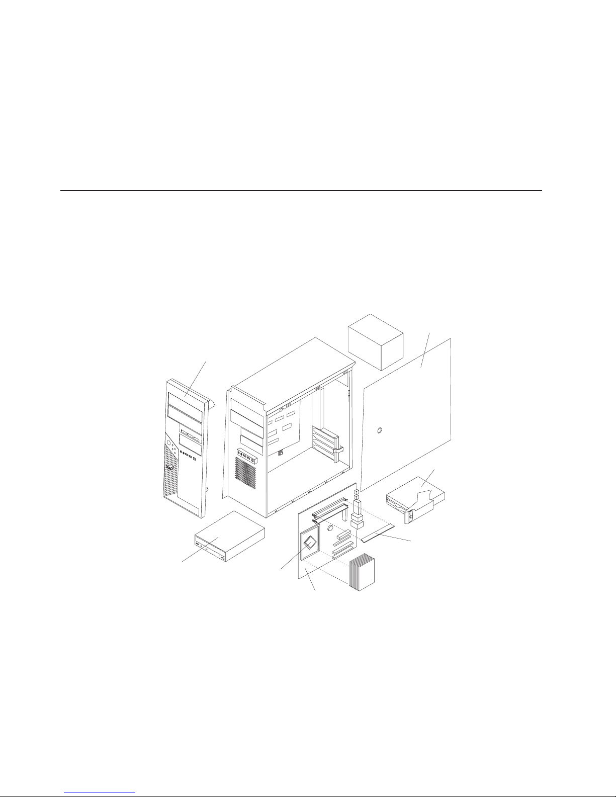
v
v
30
v
While the device is still in its static-protective package, touch it to an unpainted
metal part of the computer for at least 2 seconds. This drains static electricity
from the package and from your body.
Remove the device from its package and install it directly into the computer
without setting down the device. If it is necessary to set down the device, put it
back into its static-protective package. Do not place the device on your computer
cover or on a metal surface.
Take additional care when handling devices during cold weather. Heating reduces
indoor humidity and increases static electricity.
Installing options in your computer
This section provides instructions for installing hardware options in your computer.
Note: To install options, you might find it easier to lay the computer on its side.
Major components of your computer
The following illustration shows the major components in the M Pro Types 6225 and
6228 computers.
CD-ROM
drive
Cover
Front bezel
Drive cage
Memory modules
Microprocessor
System board
IBM IntelliStation M Pro Types 6225 and 6228: User’s Guide
Page 45
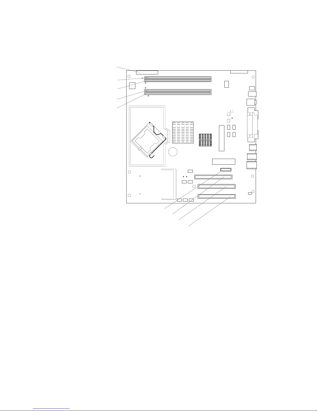
System-board option connectors
The following illustration shows the system-board connectors for user-installable
options.
Diskette drive
(optional)
DIMM 4
DIMM 3
DIMM 2
DIMM 1
Slot 1, PCI Express x1
Slot 2, PCI Express x16
Slot 3, PCI
Slot 4, PCI
Chapter 4. Installing options
31
Page 46
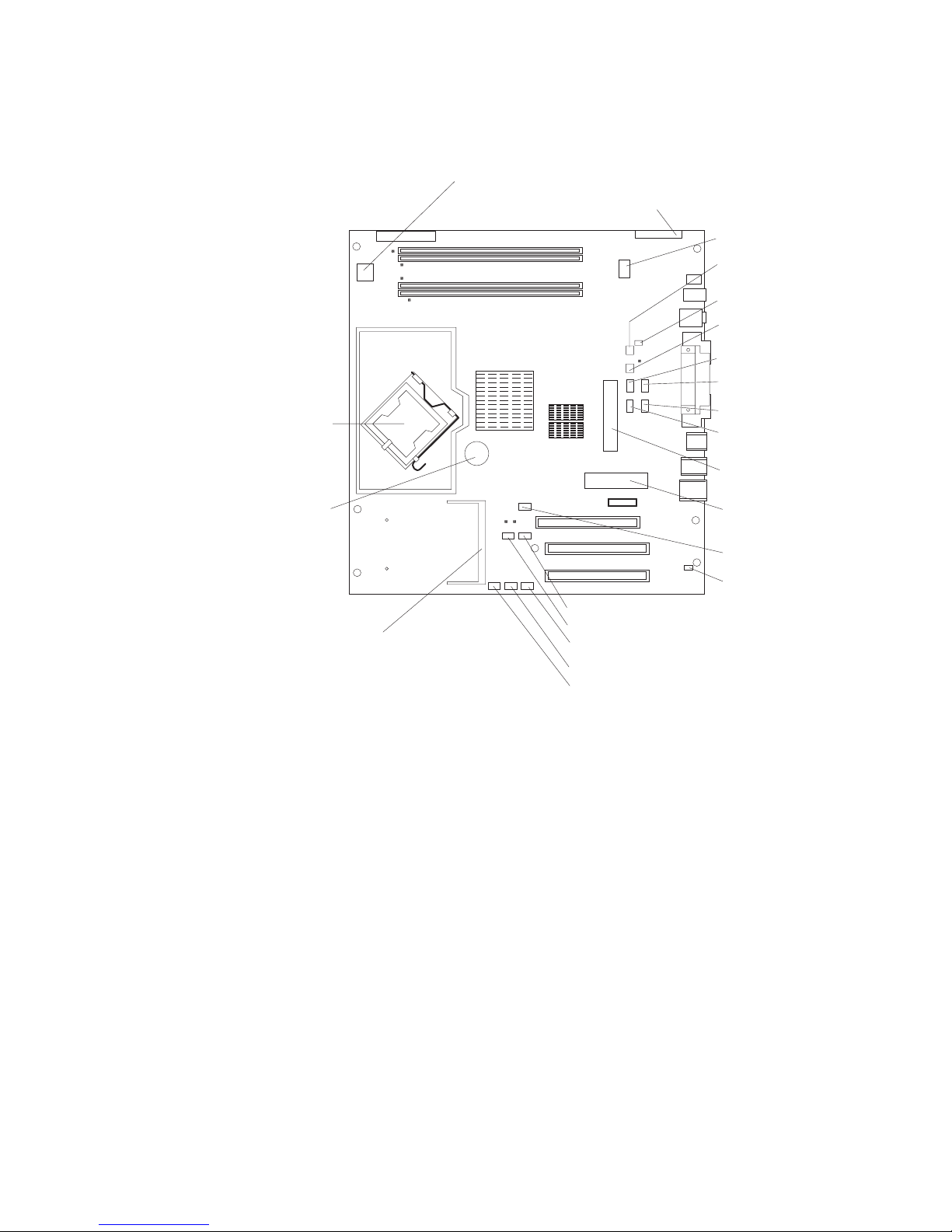
32
System-board internal connectors
The following illustration shows the internal connectors on the system board.
Microprocessor power
Front panel switch / LEDs
CD audio
Ethernet activity
LED
Internal speaker
System error
connector
SATA drive 4
SATA drive 3
Microprocessor
Battery
SCSI adapter
(mini-PCI)
Fan
Microprocessor fan
IEEE 1394 (Firewire)
enable / disable jumper
Boot block jumper
SCSI LED
SATA drive 2
SATA drive 1
IDE drive
Main power
Clear CMOS jumper
Intrusion switch
IBM IntelliStation M Pro Types 6225 and 6228: User’s Guide
Page 47
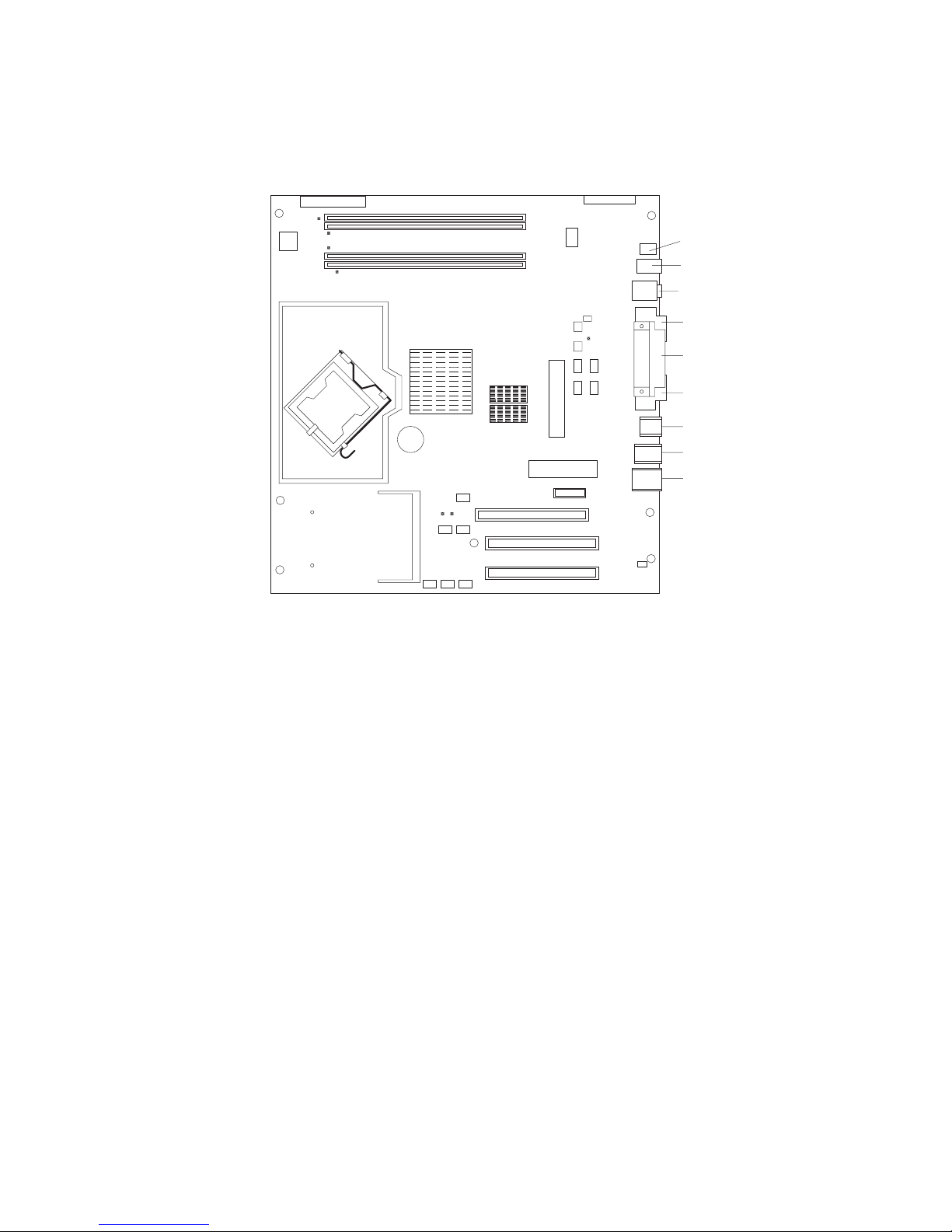
System-board external connectors
The following illustration shows the external input/output connectors on the system
board.
Internal 1394 (FireWire)
External 1394 (FireWire)
Audio in / out
Serial 2
Parallel
Serial 1
Keyboard / mouse
USBs (4)
USBs (2) /
Ethernet
Chapter 4. Installing options
33
Page 48

1.
2.
on
3.
To
1.
2.
on
3.
34
Removing the side cover
Complete the following steps to remove the side cover of the computer:
Read “Installation guidelines” on page 29.
Turn off the computer and all attached devices (see “Turning off the computer”
page 19); then, disconnect all power cords and external cables.
Press the cover-release button on the side of the computer, and push the side
cover toward the rear of the computer. Lift the side cover off the computer and
set it aside.
replace the side cover, see “Replacing the side cover” on page 49.
Attention: For proper cooling and airflow, replace the cover before turning on the
computer. Operating the computer with the cover removed might damage computer
components.
Removing the bezel
When working with some options, such as a CD-ROM drive or diskette drive, you
must first remove the bezel to access the option.
Complete the following steps to remove the bezel:
Read the safety information beginning on page vii and the guidelines in
“Handling static-sensitive devices” on page 29.
Turn off the computer and all attached devices (see “Turning off the computer”
Remove the side cover (see “Removing the side cover” on page 34).
page 19); then, disconnect all power cords and external cables.
IBM IntelliStation M Pro Types 6225 and 6228: User’s Guide
Page 49

5.
To
v
v
v
v
v
v
v
v
v
4.
Press the bezel release button to disengage the bezel.
Bezel release
button
Carefully remove the bezel from the computer; then, set the bezel aside.
reinstall the bezel, see “Replacing the bezel” on page 48.
Installing an adapter
The following notes describe the types of adapters that your computer supports and
other information that you might consider when installing an adapter. See
“System-board option connectors” on page 31 for an illustration of the adapter slot
locations.
Read the documentation that comes with your operating system.
Locate the documentation that comes with the adapter and follow those
instructions in addition to the instructions in this chapter. If you need to change
the switch or jumper settings on your adapter, follow the instructions that come
with the adapter.
Your computer comes with adapter connectors, or slots. The PCI Express x16
video adapter is installed in slot 2. You can install up to three additional optional
adapters in your computer in slot 1 (PCI Express x1) and PCI slots 3 and 4.
You can install only 33 MHz/32-bit adapters in PCI slots 3 and 4.
You can install full-length adapters in PCI slots 3 and 4. None of the expansion
slots are hot-plug slots.
For slot 3 and 4, your computer supports 5.0 V signaling and universal PCI
adapters; it does not support 3.3 V signaling adapters.
The computer scans the adapters in the following sequence to assign system
resources: PCI Express x1 slot (slot 1), PCI Express x16 slot (slot 2), PCI
expansion slot 1 (slot 3), PCI expansion slot 2 (slot 4), and mini-PCI 1 slot. Then,
the computer starts the PCI devices in the following order, if you have not
changed the default startup sequence: PCI Express x1, PCI Express x16,
system-board IDE or small computer system interface (SCSI) devices, and PCI
slot 3, PCI slot 4, and then the mini-PCI 1.
Your computer comes with integrated IEEE 1394 (FireWire) support.
For a list of supported options for your computer, go to http://www.ibm.com/pc/;
then, select your country and navigate to the list of options for your computer.
Chapter 4. Installing options
35
Page 50

1.
2.
on
3.
4.
5. If an
v
v
If
6.
7. If
36
Complete the following steps to install an adapter:
Read the safety information beginning on page “Safety” on page vii and the
guidelines in “Handling static-sensitive devices” on page 29
Turn off the computer and all attached devices (see “Turning off the computer”
page 19); then, disconnect all external cables and power cords.
Remove the side cover (see “Removing the side cover” on page 34).
Determine which PCI slot you will use for the adapter. Check the instructions
that come with the adapter for any requirements, restrictions, or cabling
instructions. It might be easier to route cables before you install the adapter.
adapter is already installed in the slot, remove it using one of the
following procedures and place it on a static-protective surface:
For full-length adapters, rotate the rear adapter-retention bracket to the open
(unlocked) position; then, release the adapter from the front
adapter-retention bracket. Grasp the adapter and pull it out of the slot.
For smaller adapters, rotate the rear adapter-retention bracket to the open
(unlocked) position. Grasp the adapter and pull it out of the slot.
the slot is empty, remove the expansion-slot cover. From the rear of the
computer, press on the slot cover. Grasp it and pull it out of the expansion slot.
Store it in a safe place for future use.
Attention: Expansion-slot covers must be installed in all empty slots. This
maintains the electronic emissions standards of the computer and ensures
proper ventilation of computer components.
Follow the instructions that come with the adapter to set jumpers or switches, if
any.
Attention: Avoid touching the components and gold-edge connectors on the
adapter.
you are installing a full-length adapter, remove the blue adapter guide (if any)
from the end of the adapter.
Attention: Make sure that the adapter is correctly seated in the expansion
slot before you turn on the computer. Incomplete installation of an adapter
might damage the system board or the adapter.
IBM IntelliStation M Pro Types 6225 and 6228: User’s Guide
Adapter guide
Page 51

9.
If
If
If
8.
Carefully grasp the adapter by the top edge or upper corner and move the
adapter directly from the static-protective package to the adapter slot. Align the
adapter with the expansion slot guides; then, press the adapter firmly into the
expansion slot.
Attention: Make sure that the adapter is correctly seated in the expansion
slot before you turn on the computer. Incomplete installation of an adapter
might damage the system board or the adapter.
Rear adapter-retention
bracket
Rotate the rear adapter-retention bracket to the closed (locked) position.
10.
Connect required cables to the adapter. Route cables so that they do not block
the flow of air from the fans. If you are installing an optional SCSI adapter, see
“Cabling an optional SCSI adapter” on page 38 for additional information.
11.
you have another adapter to install, repeat steps 4 through 10..
12.
you have installed a full-length adapter, press down on the top tab of the
front adapter-retention bracket to lock it in place (the tab is inside the fan
compartment that is next to the front adapter-retention bracket).
Note: If any adapter in your computer is large or has heavy cables attached to
it, you can secure the adapter with a screw. Insert one backup
expansion-slot screw through the top of each adapter bracket into the
screw hole and secure the adapter before proceeding to the next step.
13.
you have other options to install, do so now; otherwise, replace the side
cover (see “Replacing the side cover” on page 49), reconnect the external
cables and power cords, and turn on the computer.
Chapter 4. Installing options
37
Page 52

1. An
2.
1.
2.
3.
4.
38
Cabling an optional SCSI adapter
You can install an optional SCSI adapter in your computer to control the internal
hard disk drives. With a SCSI adapter installed, you can configure the internal hard
disk drives into disk arrays. You can also cable a SCSI adapter to external hard
disk drives. See your SCSI adapter option documentation for complete instructions
for installing a SCSI adapter in your computer and for additional information about
SCSI adapters.
Notes:
optional SCSI adapter is required for you to connect external SCSI devices.
The SCSI cables that are used by the integrated SCSI controller cannot be
used with an optional SCSI adapter.
Complete the following steps to cable an optional SCSI adapter:
Install the SCSI adapter (see “Installing an adapter” on page 35).
Connect the SCSI-signal cable to the adapter and one or more of the signal
cable connectors to the rear of the SCSI devices.
Connect the SCSI-activity-indicator cable to the adapter and to the SCSI-LED
connector on the system board. See “System-board internal connectors” on
page 32 for the location of the SCSI-LED connector.
SCSI adapter
SCSI signal cable
connector
SCSI signal cable
Complete the installation of the optional SCSI adapter.
IBM IntelliStation M Pro Types 6225 and 6228: User’s Guide
Page 53

v
v
v
v
v
v
v
v
v
v
a
v
Installing a drive
Depending on your computer model, one or more of the following drives might be
installed in your computer:
The IntelliStation M Pro Types 6225 and 6228 computers come with an IDE
CD-ROM, CD-RW, or DVD/CD-RW drive in bay 1 and a 3.5-in. hard disk drive in
bay 5.
Diskette (optional)
Hard disk
CD-ROM, CD-RW, or DVD/CD-RW combo
Bay 1
Bay 5
Bay 2
Bay 3
Bay 4
The following notes describe the types of drives that your computer supports and
other information that you must consider when installing drives:
Diskette drives, tape drives, CD-ROM, DVD/CD-RW, and DVD-ROM drives are
examples of removable-media drives. You can install removable-media drives in
bays 1, 2, 3, and 4 only.
You can install a 3.5-in. slim-high or 5.25-in. half-high removable-media drive,
such as a tape backup drive, in bay 2.
You can install only a 3.5-in., slim-high drive in bay 3 or 4.
The IntelliStation M Pro Types 6225 and 6228 computers support only one
diskette drive.
There are four serial ATA hard disk drive connectors on the system board.
You can mix and match SCSI and serial ATA drives in bays 3, 4, and 5.
The electromagnetic interference (EMI) integrity and cooling of the computer are
protected by having all bays and PCI slots covered or occupied. When you install
drive or PCI adapter, save the EMC shield and filler panel from the bay or the
PCI adapter slot cover in the event you later remove the option.
For a complete list of supported options for your computer, go to
http://www.ibm.com/pc/; then, select your country and navigate to the list of
options for your computer.
Chapter 4. Installing options
39
Page 54

1.
2.
3.
4.
5.
or
v Do
v
40
Installing a drive in bay 2, 3, or 4
Complete the following steps to install a drive in bay 2, 3, or 4:
Read the safety information beginning on page “Safety” on page vii, the
guidelines in “Handling static-sensitive devices” on page 29, and the
documentation that comes with your drive.
Turn off the computer and all attached devices; then, disconnect all external
cables and power cords.
Remove the side cover (see “Removing the side cover” on page 34).
Remove the bezel (see “Removing the bezel” on page 34).
Use a screwdriver to pry the filler panel and EMC shield away from the
computer.
Filler panel
EMC shield
Drive retainer
clip
Note: If you are installing a drive that contains a laser, observe the following
safety precaution.
Statement 3:
CAUTION:
When laser products (such as CD-ROMs, DVD drives, fiber optic devices,
transmitters) are installed, note the following:
could result in exposure to hazardous laser radiation. There are no
serviceable parts inside the device.
Use of controls or adjustments or performance of procedures other
than those specified herein might result in hazardous radiation
exposure.
IBM IntelliStation M Pro Types 6225 and 6228: User’s Guide
not remove the covers. Removing the covers of the laser product
Page 55

6.
on a
7.
8.
v To
a.
b. If
To
– If
a.
b.
If
a.
b.
DANGER
Some
laser products contain an embedded Class 3A or Class 3B laser
diode. Note the following.
Laser radiation when open. Do not stare into the beam, do not view
directly with optical instruments, and avoid direct exposure to the
beam.
Class 1 Laser Product
Laser Klasse 1
Laser Klass 1
Luokan 1 Laserlaite
Appareil A Laser de Classe 1
`
Touch the static-protective package containing the drive to any unpainted metal
surface on the computer; then, remove the drive from the package and place it
static-protective surface.
Set any jumpers or switches on the drive according to the documentation that
comes with the drive.
Note: You might find it easier to install the new drive from the front and then
attach the cables.
Use one of the following procedures, depending on which bay you are
installing the drive in:
install a drive in bay 2, complete the following steps:
Remove the large drive clip that is attached to the side of bay 2 of the
drive cage for bays 1, 2, 3, and 4 (see the figure in step 5). Slide the
drive clip to the left to disengage it from the drive cage; then, snap the
drive clip into the screw holes on the side of the drive.
you are installing a 5.25-in. drive in bay 2, slide the drive into the drive
bay until it snaps in place.
install a drive in bay 3 or 4, complete the following steps:
v
Note: Only a 3.5-in. device can be installed in bay 3 or 4.
you are installing an external media device, complete the following
steps:
Remove the small drive clip that is attached to the bottom of the drive
cage for bays 1, 2, 3, and 4 (see the figure in step 5). Slide the drive
clip to disengage it from the drive cage; then, snap the drive clip into
the screw holes on the side of the drive.
Slide the drive into the drive bay until it snaps in place.
you are installing a hard disk drive, complete the following steps:
–
Push the drive into the bay from the rear of the drive cage.
Use the two screws to attach the drive to the drive cage.
Chapter 4. Installing options
41
Page 56

If
If
v
v
1.
2.
on
3.
4.
42
9.
Determine whether the drive is an IDE, SATA, or SCSI device; then, connect
one end of the applicable signal cable into the back of the drive and make
sure that the other end of this cable is connected into the applicable IDE,
SATA, or SCSI connector.
10.
Route the signal cable so that it does not block the airflow to the rear of the
drives or over the microprocessor.
11.
12.
you have another drive to install or remove, do so now.
Connect the power cable to the back of the drive. The connectors are keyed
and can be inserted only one way.
13.
you have other options to install or remove, do so now; otherwise, replace
the bezel (see “Replacing the bezel” on page 48).
Installing a SCSI or SATA drive in bay 5
Bay 5 is inside the computer, below the power supply and within a drive cage.
Note: When installing options, you might find it easier to work with the computer
lying on its side.
Before you install a hard disk drive in bay 5, read the following information:
Read the documentation that comes with the drive for cabling instructions.
Route the cable before you install the drive. Do not block the airflow from the
fans.
Complete
the following steps to install a SCSI or SATA drive in bay 5:
Read the safety information beginning on page “Safety” on page vii and the
guidelines in “Handling static-sensitive devices” on page 29.
Turn off the computer and all attached devices (see “Turning off the computer”
page 19); then, disconnect all external cables and power cords.
Remove the cover (see “Removing the side cover” on page 34).
Push the drive-cage retention latch toward the front of the computer and hold
the latch in place. While holding the latch in place, grasp the drive-cage handle
and rotate the cage until it locks into place with the drive-cage retention latch.
The installed drive will face you.
Note: As you rotate the drive cage, make sure the hard disk drive cables or
other internal cables do not impede the rotation of the drive cage.
IBM IntelliStation M Pro Types 6225 and 6228: User’s Guide
Page 57

6.
7.
Drive-cage
retention latch
Drive-cage
handle
5.
Slide the existing drive out of the drive bay. Remove the drive from the drive
tray by pulling on the handle; then, slide the drive out of the drive tray.
Drive-tray
handle
Touch the static-protective package that contains the new drive to any
unpainted metal surface on the computer; then, remove the drive from the
package and place it on a static-protective surface.
Set any jumpers or switches on the new drive according to the documentation
that comes with the drive.
Chapter 4. Installing options
43
Page 58

9.
of
If
44
8.
Attach the new drive to the drive tray. Place the drive on the drive tray and
align the holes on the drive with the mounting pins on the drive tray. Gently
pull both sides of the drive tray outward and insert the mounting pins into the
holes on the drive.
Align the drive assembly with the guide rails in the bay (make sure that the
connector end of the drive is facing you).
10.
Gently slide the drive tray into the drive cage until the tray snaps into place.
11.
Determine whether the new drive is a SATA or SCSI device; then, connect one
end of the applicable signal cable into the back of the drive and the other end
this cable into the applicable SATA or mini-PCI SCSI connector. See “Power
and signal cables for internal drives” on page 45 for additional information
about cabling drives and “System-board option connectors” on page 31 for the
location of SATA and mini-PCI SCSI connectors on the system board. If there
are open connectors on the cables that connect existing SATA or SCSI drives,
these cables can be used to connect the new drive.
12.
Route the signal cable so that it does not block the airflow to the rear of the
drives or over the microprocessor.
13.
Connect the power cable to the back of the drive. The connectors are keyed
and can be inserted only one way.
14.
Push the drive-cage retention latch toward the front of the computer; then,
rotate the drive cage back into the computer.
Note: As you rotate the drive cage, make sure the hard disk drive cables or
other internal cables do not impede the rotation of the drive cage.
15.
you have other options to install or remove, do so now.
IBM IntelliStation M Pro Types 6225 and 6228: User’s Guide
Page 59

32
v
v
v If
v If
v
At
at
v
–
–
–
–
Power and signal cables for internal drives
Your computer uses cables to connect IDE, SATA, and SCSI devices to the power
supply and to the system board. (See “System-board internal connectors” on page
for the location of system-board connectors.) Review the following information
before connecting power and signal cables to internal drives:
The drives that are preinstalled in your computer come with power and signal
cables attached. If you replace any drives, remember which cable is attached to
which drive.
When you install a drive, make sure that one of the drive connectors of the signal
cable is connected to the drive and that the connector at the other end of the
signal cable is connected to the system board.
you have only one IDE device on a cable, it must be set as a primary device.
two IDE devices are used on a single cable, one must be designated as the
primary device and the other as the secondary device; otherwise, the computer
might not recognize some of the IDE devices. The primary and secondary
designation is determined by switch or jumper settings on each IDE device.
The following cables are provided:
Power cables: Four-wire power cables connect the drives to the power supply.
the end of these cables are plastic connectors that can be attached to
different drives; these connectors vary in size. You can use either a four-wire
power cable or serial ATA power cable with serial ATA drives, but do not use both
the same time (use one or the other).
Signal cables: Signal cables are typically flat cables, also called ribbon cables,
that connect parallel IDE, SATA, SCSI, and diskette drives to the system board.
Two or three types of signal cable come with your computer:
IDE: The wider IDE signal cable has three connectors. One of these
connectors is attached to the drive, one is a spare, and the third is attached to
the primary IDE connector on the system board.
The CD-ROM drive is attached to an ATA 100 signal cable. ATA 100 signal
cables are color-coded. The blue connector is attached to the system board.
The black connector is attached to the primary IDE device. The gray middle
connector is attached to the secondary IDE device.
Diskette drive (optional): The narrower signal cable has two connectors.
One is attached to the diskette drive, and the other is attached to the diskette
drive connector on the system board.
Serial ATA: The narrower, black signal cable has two connectors. One is
attached to the SATA drive, and the other is attached to the connector on the
system board. Each SATA drive comes with a cable. If you install an additional
SATA drive, you will need an additional cable. SATA signal cables should be
connected to the system board connectors (SATA 1 thourgh SATA 4) in
numerical order, starting with SATA 1.
SCSI: The Ultra320 twisted ribbon cable connects the internal Ultra320 SCSI
hard disk drive to the mini-PCI SCSI connector. This cable has three
additional connectors for attaching more internal SCSI devices.
Chapter 4. Installing options
45
Page 60

v
v
v
v
a
v
v
v
v
1.
2.
on
3.
4.
5.
2
1, 3 4
1, 3, 2, 4 46
Installing memory modules
The following notes describe the types of dual inline memory modules (DIMMs) that
your computer supports and other information that you must consider when
installing DIMMs:
When you restart the computer after adding or removing a DIMM, the computer
displays a message that the memory configuration has changed.
Your computer uses industry-standard PC2-3200 double-data-rate 2 (DDR2)
DIMMs.
The system board contains four DIMM connectors and supports two-way memory
interleaving.
The DIMM options available for your computer are 256 MB, 512 MB, and 1 GB,
which come in matched pairs. Your computer supports a minimum of 512 MB and
maximum of 4 GB of system memory.
Your computer comes with either two 256 MB or two 512 MB memory DIMMs
that are installed in DIMM 1 and DIMM 3 memory connectors. The second pair of
DIMMs must be installed in DIMM 2 and DIMM 4 memory connectors.
DIMMs must be installed in matched pairs. The DIMMs in each pair must be the
same size, speed, type, and technology as each other but do not have to match
the other pairs. You can mix compatible DIMMs from various manufacturers.
Install only 1.8 V, 240-pin, DDR2, PC2-3200, unbuffered synchronous dynamic
random-access memory (SDRAM) with error correcting code (ECC) DIMMs.
These DIMMs must be compatible with the latest PC2-3200 SDRAM unbuffered
DIMM specification. For a list of supported options for your computer, go to
http://www.ibm.com/pc/; then, select your country and navigate to the list of
options for your computer.
The amount of usable memory will be reduced depending on the system
configuration. A certain amount of memory must be reserved for system
resources. The BIOS will display the total amount of installed memory and the
amount of configured memory.
Complete the following steps to install a DIMM:
Read the safety information beginning on page vii, and the guidelines in
“Handling static-sensitive devices” on page 29.
Turn off the computer and all attached devices (see “Turning off the computer”
page 19); then, disconnect all power cords and external cables.
Remove the side cover (see “Removing the side cover” on page 34).
For easier access to the memory modules, rotate the drive cage out of the
computer. Grasp the drive cage and rotate it until it locks into place.
Locate the DIMM connectors on the system board. Determine the connectors
into which you will install the DIMMs. Remember that DIMM 1 and DIMM 3
must be paired together (and must be the first installed pair) and DIMM 2 and
DIMM 4 must be paired together. The following table shows the installation
sequence.
Memory installation sequence
DIMMs
DIMMs
DIMMs
Slots
IBM IntelliStation M Pro Types 6225 and 6228: User’s Guide
Page 61
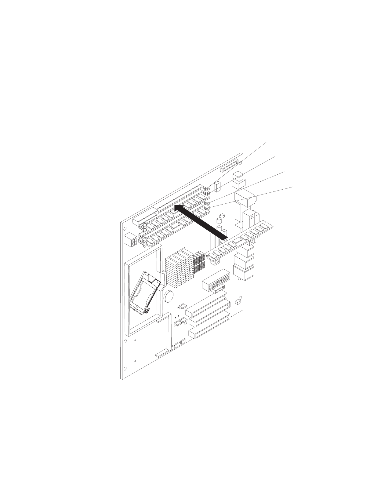
7.
8.
so
9.
If
6.
Gently open the retaining clips and, if necessary, remove any existing DIMM.
Touch the static-protective package that contains the DIMM to any unpainted
metal surface on the computer. Then, remove the new DIMM from the
package.
Gently open the retaining clip on each end of the DIMM slot. Turn the DIMM
that the pins align correctly with the connector.
Insert the DIMM into the connector. Firmly press the DIMM straight down into
the connector by applying pressure on both ends of the DIMM simultaneously.
The retaining clips snap into the locked position when the DIMM is firmly
seated in the connector. If there is a gap between the DIMM and the retaining
clips, the DIMM has not been correctly installed. Open the retaining clips and
remove the DIMM; then, reinsert it.
DIMM
connector 4
DIMM
connector 3
DIMM
connector 2
DIMM
connector 1
10.
you have other options to install or remove, do so now; otherwise rotate the
cage back into the computer.
11.
Replace the side cover (see “Replacing the side cover” on page 49).
12.
Reconnect the external cables and power cords. Turn on the attached devices,
and turn on the computer.
Chapter 4. Installing options
47
Page 62

To
it
v A
v A
1.
2.
or
3. If
4.
1.
2.
48
Installing a security cable
help prevent hardware theft, you can thread a security cable through the cable
loop on the rear of your computer. After you add the security cable, make sure that
does not interfere with other cables that are connected to the computer.
Before you begin, obtain the following items:
security cable
lock, such as a combination lock or padlock
Complete the following steps to install a security cable:
Turn off the computer and all attached devices; then, disconnect all power cords
and external cables.
Thread the cable through the cable loop and around an object that is not part of
permanently secured to the building structure or foundation and from which
the cable cannot be removed. Fasten the cable ends together with a lock. After
you add the security cable, make sure that it does not interfere with other
cables that are connected to the computer.
you have other options to install or remove, do so now.
Reconnect the external cables and power cords. Turn on the attached devices,
and turn on the computer.
Replacing the bezel
Complete the following steps to replace the bezel:
Insert the tabs on the back of the bezel into the matching holes on the computer
chassis.
Push the bezel toward the computer until the tabs snap into place.
IBM IntelliStation M Pro Types 6225 and 6228: User’s Guide
Cable loop
Page 63

1.
2.
3.
4.
1.
2.
on
3.
to
If
Replacing the side cover
Complete the following steps to replace the side cover:
Make sure that all cables, adapters, and other components are installed and
seated correctly and that you have removed all work tools or parts from inside
the computer.
Install the side cover by placing it into position on the computer. Be certain that
the lip on the bottom of the cover rests on the ledge on the bottom of the
chassis. Slide the side cover forward to lock the side cover.
Reconnect the external cables and power cords to the computer; then, connect
the power cords to electrical outlets.
Turn on the attached devices; then, turn on the computer.
Connecting external options
You can connect a number of optional external devices to the connectors on the
rear and front of the computer.
Complete the following steps to connect an external device:
Read the safety information beginning on page vii, the guidelines in “Handling
static-sensitive devices” on page 29, and the documentation that comes with
your options.
Turn off the computer and all attached devices (see “Turning off the computer”
page 19).
Follow the instructions that come with the option to prepare it for installation and
connect it to the computer.
you are attaching a SCSI device, see “Ultra320 SCSI connector” on page 53 for
SCSI ID and cabling information.
Chapter 4. Installing options
49
Page 64
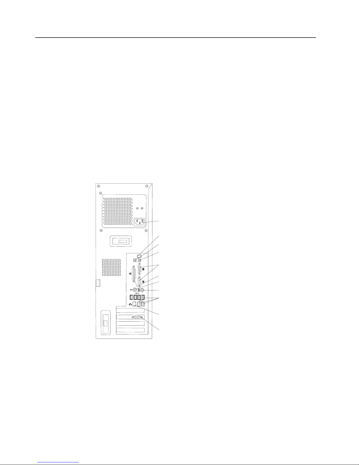
v
v
v
v
v
v
v
v
v
v
v
50
Input/output connectors
Connect optional external devices to the connectors on the front and rear of the
computer.
Your computer has the following input/output (I/O) connectors:
One audio line in
Two audio line out
One audio microphone
One Ethernet
Two IEEE 1394 (FireWire)
One keyboard
One mouse
One parallel
Two serial
Eight Universal Serial Bus (USB) 2.0
One video
The following illustration shows the locations of the connectors on the M Pro Types
6225 and 6228.
Power cord
IEEE 1394 (FireWire)
Line in
Line out
Serial
Parallel
Mouse
Keyboard
USBs
Ethernet
Video
The following sections describe these connectors.
IBM IntelliStation M Pro Types 6225 and 6228: User’s Guide
Page 65

Audio connectors
Use the audio connectors to connect external audio equipment to the computer.
The following illustration shows the audio connectors.
Line out
(green)
Line in
(blue)
Mic
(pink)
Line in
There is one line-in connector on the rear of the computer. The computer receives
audio signals through this connector from an external audio device.
Line out
There are two line-out connectors, one on the front and one on the rear of the
computer. The computer sends audio signals through this connector to powered
speakers with built-in amplifiers, headphones, a multimedia keyboard, or the audio
line-in connector on a stereo system. The internal speaker in the computer is
disabled when a device is attached to this connector.
Mic
There is one microphone connector on the front of the computer. Connect a
microphone to this connector to record sounds onto the hard disk or to use
speech-recognition software.
Auxiliary-device (pointing-device) connector
There is one auxiliary-device connector on the rear of the computer. Use this
connector to connect a mouse or other pointing device. The following illustration
shows an auxiliary-device connector.
6
4
2
5
3
1
Ethernet (RJ-45) connector
There is one Ethernet connector on the rear of the computer. Use this connector to
connect the computer to a 10-Mbps, 100-Mbps, or 1000-Mbps network. The
following illustration shows an Ethernet connector.
Activity LED
(green)
8
Connect a Category 3, 4, or 5 unshielded twisted-pair (UTP) cable to this connector.
The 100BASE-TX and 1000BASE-T Fast Ethernet standards require Category 5 or
higher cabling.
The Ethernet connector has one LED that indicates Ethernet-link status. When this
LED is lit, it indicates that there is an active connection on the Ethernet port. Activity
between the computer and the network is indicated by the Ethernet transmit/receive
activity LEDs on the front and rear of the computer (see “Controls and LEDs” on
page 9).
Link LED
(green)
1
Chapter 4. Installing options
51
Page 66

If
52
IEEE 1394 (FireWire) connector (some models)
There is one 4-pin Institute of Electrical and Electronics Engineers (IEEE) 1394
(FireWire) connector on the front of the computer and one 6-pin IEEE 1394
(FireWire) connector on the rear of the computer. Use these connectors to connect
IEEE 1394 (FireWire) devices. The following illustrations show the IEEE 1394
(FireWire) connectors.
4-pin IEEE 1394 (FireWire) connector (front)
3
4
21
6-pin IEEE 1394 (FireWire) connector (rear)
4
2
6
1
Keyboard connector
There is one keyboard connector on the rear of the computer. Use this connector to
connect a PS/2 (non-USB) keyboard. The following illustration shows a keyboard
connector.
6
4
2
you attach a keyboard to this connector, Universal Serial Bus (USB) ports and
devices are disabled during the power-on self-test (POST).
Parallel connector
There is one parallel connector on the rear of the computer. Use this connector to
connect a parallel device. The following illustration shows a parallel connector.
13
25
The parallel connector supports three standard IEEE 1284 modes of operation:
standard parallel port (SPP), enhanced parallel port (EPP), and extended capability
port (ECP). If you configure the parallel port to operate in bidirectional mode, it
supports the ECP and EPP modes. When the parallel connector is configured as
bidirectional, use an IEEE 1284-compliant cable that does not exceed 3 meters (9.8
ft). Use the Devices and I/O Ports options in the IBM Configuration/Setup Utility
program to configure the parallel connector as bidirectional.
3
5
5
3
1
1
14
IBM IntelliStation M Pro Types 6225 and 6228: User’s Guide
Page 67

to
v
v
v
v An
Serial connectors
There are two serial connectors on the rear of the computer. Use these connectors
connect serial devices. The following illustration shows a serial connector.
1
69
Ultra320 SCSI connector
Your computer might have a mini-PCI SCSI controller. This single-channel controller
supports an independent, Ultra320 SCSI channel that supports up to 15 SCSI
devices. The SCSI connector for the channel is on the mini-PCI SCSI controller.
The controller has the following features:
Double-transition clocking to achieve up to 320 MBps (megabytes per second)
data-transfer rates
Domain name validation to negotiate compatible data-transfer speeds with each
device
Cyclic-redundancy checking (CRC) to improve data reliability
active terminator for SCSI bus termination
The following illustration shows a SCSI connector.
34
68
5
1
35
SCSI cabling requirements
You can install three internal SCSI devices using the SCSI signal cable that comes
with some computer models. If you plan to attach external SCSI devices, you can
order an optional SCSI adapter and external cable. To select and order the correct
cables for use with external devices, contact your IBM marketing representative or
authorized reseller. To receive an indication of SCSI hard-disk drive activity, you
must also connect the SCSI adapter to the SCSI LED connector on the system
board. See “System-board option connectors” on page 31 for the locations of the
SCSI connectors.
Setting SCSI IDs
Each SCSI device that is connected to a SCSI controller must have a unique SCSI
ID. This ID enables the SCSI controller to identify the device and ensure that
different devices on the same SCSI channel do not attempt to transfer data
simultaneously. SCSI devices that are connected to different SCSI channels can
have duplicate SCSI IDs. See the information that comes with the device for
instructions for setting its SCSI ID.
Chapter 4. Installing options
53
Page 68

is on
54
Universal Serial Bus connectors
There are eight USB 2.0 connectors, two on the front and six on the rear of the
computer. Use the USB connectors to connect optional telephony and multimedia
devices. USB 2.0 technology transfers data at up to 480 Mb per second (Mbps)
with a maximum of 127 external devices and a maximum signal distance of 5
meters (16 ft) per segment (if the device that is attached to the computer is a USB
2.0 device). If multiple USB devices are attached to the computer, the USB hub
must be USB 2.0; otherwise, all USB 2.0 devices will transfer data at 12 Mbps.
Using Plug and Play technology, USB devices are configured automatically. The
following illustration shows a USB connector.
14
Use a 4-pin USB cable to connect an external device to a USB connector.
Video connector
The PCI Express x16 adapter (slot 2) provides the video connector. This connector
other display device. The following illustrations show examples of different video
connectors.
Analog video connector
Digital (DVI-I) video connector
Dual monitor system-59 (DMS-59) video connector
the rear of the computer. Use the video connector to connect a monitor or
5
1
1
1115
C1 C2
C3C5C4
IBM IntelliStation M Pro Types 6225 and 6228: User’s Guide
Page 69

Some models come with a digital video interface (DVI) connector for connecting a
digital monitor. If you have problems viewing information with a second monitor, see
“Changing monitor settings” on page 15.
Models with the NVIDIA Quadro FX 1300 or NVIDIA Quadro FX 3400 video adapter
come with a DVI-I to VGA style analog converter for each DVI-I connector.
Important: To get the best performance from the NVIDIA Quadro FX 3400 video
adapter, you must connect the video adapter to the computer power
supply. Otherwise, the video adapter will be operating with very limited
power, resulting in a decrease in performance for some applications.
Use the PCI Express x16 external power drop to connect the video
adapter to the computer power supply. The following illustration shows
the location of the video adapter power connector.
Video adapter
power connector
Models with the NVIDIA Quadro NVS 280 video adapter come with a dual monitor
system-59 (DMS-59) to dual-analog monitor pigtail cable. If you want to set up two
digital monitors, you must purchase a separate dual-digital monitor cable.
Chapter 4. Installing options
55
Page 70

56
IBM IntelliStation M Pro Types 6225 and 6228: User’s Guide
Page 71

If
v
v
v
of
v
v
An
©
Chapter 5. Solving problems
This section provides basic troubleshooting information to help you diagnose and
solve some problems that might occur.
you cannot locate and correct the problem using the information in this chapter,
see Appendix A, “Getting help and technical assistance,” on page 89 for more
information.
Diagnostic tools overview
The following tools are available to help you identify and solve hardware-related
problems:
Computer Support flowchart
The Computer Support flowchart on the following page will help you determine
how to access help from IBM and register your computer.
POST beep codes and error messages
The power-on self-test generates beep codes and messages to indicate
successful test completion or the detection of a problem. See “Power-on self-test
(POST)” on page 59 for more information. Additional information is recorded in
the system error logs. (For detailed information, see the information about error
logs in “Configuration/Setup Utility menu choices” on page 22.
Diagnostic programs
The system diagnostic programs are on a hidden partition on your computer hard
disk. These programs are the primary methods of testing the major components
your computer. See “Diagnostic programs and error messages” on page 65 for
more information.
Troubleshooting charts
This charts lists problem symptoms and steps to correct each problem. See the
“Troubleshooting charts” on page 73 for more information.
System-board error LEDs
LED on the system board might also be lit to help isolate an error that is
indicated by the system error LED on the front of the computer. See the
“System-board error LEDs” on page 79 for more information.
Copyright IBM Corp. 2004
57
Page 72
Computer Support
Computer working
properly?
Ye s
No
Check all cables for loose connections
and verify that all optional devices you
installed are on the compatibility matrix.
You can view the atcompatibility matrix
http://www.pc.ibm.com/us/compat/
intellistation/
Problem
solved?
Ye s
No
Use the troubleshooting
information provided with
your computer to determine
the cause of the problem
and the action to take.
Register your computer. Go to
http://www.ibm.com/pc/register/
View information about IBM Support
Line at
http://www.ibm.com/services/sl/products/
or view support telephone numbers at
http://www.ibm.com/planetwide/
View support telephone numbers at
http://www.ibm.com/planetwide/
Problem
solved?
Ye s
No
Flash the latest levels of BIOS,
and download the latest level of
diagnostics. You can download
this code at
http://www.ibm.com/pc/support/
58
IBM IntelliStation M Pro Types 6225 and 6228: User’s Guide
Ye s
Problem
solved?
No
Hardware
Software
Hardware
or Software
problem?
Page 73

If
If
1. If
2. A
to
No
If no
Power-on self-test (POST)
When you turn on the computer, POST performs a series of tests to check the
operation of system components and some of the installed options.
POST finishes without detecting any problems, the first window of your operating
system or application program opens.
POST detects a problem, more than one beep sounds, and an error message
appears on your screen.
Notes:
you have set a user password, you must type the password and press Enter,
when prompted, before the operating system will start.
single problem might cause several error messages. When this occurs, work
correct the cause of the first error message. After you correct the cause of
the first error message, the other error messages usually will be resolved the
next time you run the test.
POST beep codes
The following beep codes are possible:
Continuous beep
Beep codes for specific failures
beeps
beep occurs after your computer completes POST, call for service.
Your startup (boot) microprocessor has failed, or your system board or
speaker subsystem might contain a failing component. If the system
continues through POST with no errors, call for service. If no video appears,
the startup processor has failed.
Beep codes indicating specific system problems are listed in the following
table.
Chapter 5. Solving problems
59
Page 74

or
No
or
60
Table 2. POST beep codes
Beep code Description
1-1-3
1-1-4
1-2-1
1-2-2
1-2-3
1-3-1
CMOS write/read test has failed.
BIOS EEPROM checksum has failed.
Programmable Interval Timer test has failed.
DMA initialization has failed.
DMA page register write/read test has failed.
First 64 Kb RAM test has failed.
Action
Call for service
Reseat the
memory modules
install a
memory module. If
the problem
persists, call for
service.
2-1-1
2-1-2
2-1-3
2-1-4
2-2-2
2-2-3
2-4-1
3-1-1
3-1-2
3-1-3
3-1-4
3-2-1
3-2-2
3-3-2
3-3-3
Secondary DMA register test has failed.
Primary DMA register test has failed.
Primary interrupt mask register test has failed.
Secondary interrupt mask register test has failed.
Keyboard controller test has failed.
CMOS power failure and checksum checks have failed.
Screen test indicates the screen is operable.
Timer tick interrupt test has failed.
Interval timer channel 2 test has failed.
RAM test has failed above address 0FFFFH.
Time-of-Day clock test has failed.
Serial port test has failed.
Parallel port test has failed.
Critical SMBUS error occurred (I2C bus has failed).
optional memory in the system.
Call for service
Call for service
Call for service
Reseat the
memory modules
Attention: In some memory configurations, the 3-3-3
beep code might sound during POST followed by a
blank display screen. If this occurs and the Boot Fail
Count feature in the Start Options of the IBM
Configuration/Setup Utility program is set to Enabled
install a
memory module. If
the problem
remains, call for
service.
(its default setting), you must restart the computer three
times to force the system BIOS code to reset the
memory connector from Disabled to Enabled.
IBM IntelliStation M Pro Types 6225 and 6228: User’s Guide
Page 75

1.
2.
A
A
v A
v A
v A
v A
v An
v An
If
If
POST error messages
The following table provides information about the POST error messages that can
appear during startup.
Table 3. POST error messages
POST message
062
101, 102, and 106 An error occurred during the system board and microprocessor test.
151
161
Description
The computer failed to start on three consecutive attempts.
All caches are disabled. Repeatedly turning the computer on and then off or resetting the
computer might cause this problem.
Action: Take the following steps to correct the problem:
Start the Configuration/Setup Utility program and verify that all settings are correct. Use the
Cache Control selection in the Advanced Setup menu of the Configuration/Setup Utility
program to enable the caches.
Install a new battery. See “Replacing the battery” on page 87 for instructions.
If
the problem remains, call for service. When the problem is corrected, be sure to enable the
caches.
Action: Call for service.
real-time clock (RTC) error occurred.
Action: Call for service.
The real-time clock battery has failed.
Action: Replace the battery yourself or call for service.
162
163
You can use the computer until you replace the battery. However, you must run the
Configuration/Setup Utility program and set the time and date and other custom settings each
time you turn on the computer.
change in device configuration occurred. This error occurs under one or more of the
following conditions:
new device has been installed.
device has been moved to a different location or cable connection.
device has been removed or disconnected from a cable.
device is failing and is no longer recognized by the computer as being installed.
external device is not turned on.
invalid checksum is detected in the battery-backed memory.
Action:
Make sure that all external devices are turned on. You must turn on external devices
before turning on the computer.
you did not add, remove, or change the location of a device, a device is probably failing.
Running the Diagnostic program might isolate the failing device. See “Creating an IBM
Enhanced Diagnostics diskette” on page 82 and “Using the IBM Enhanced Diagnostics
diskette” on page 83.
the problem remains, call for service.
The time of day has not been set.
Action: Set the correct date and time. If the date and time are set correctly and saved, but
the 163 error message reappears, call for service.
You can use the computer until the system is serviced, but any application programs that use
the date and time will be affected.
Chapter 5. Solving problems
61
Page 76

A
1. If
2. If
If
A
If
An
to
A
A
An
v
v A
v A
1. If
2. If
An
1. If
2. If
62
Table 3. POST error messages (continued)
POST message
164
Description
change in the memory configuration occurred. This message might appear after you add or
remove memory.
Note: The computer can be used with decreased memory capacity.
Action: Take the following steps to correct the problem:
POST error message 289 also occurred, follow the instructions for that error message
first.
you just installed or removed memory, run the Configuration/Setup Utility program; then,
exit, saving the new configuration settings.
the message appears again, shut down the computer, reseat the memory modules, and
restart the computer.
If
the problem remains, call for service.
175
vital product data (VPD) error occurred.
Action: Call for service.
184
The power-on password information stored in your computer has been removed.
Action: From the Configuration/Setup Utility program main menu, select System Security.
Then, follow the instructions on the screen.
187
189
196
198
201
289
this information cannot be restored, call for service.
The VPD serial number is not set.
Action: The system serial number is set in the VPD EEPROM at the time of manufacturing. If
the system board has been replaced, the system serial number will be invalid and should be
set. From the main menu of the Configuration/Setup Utility program, select System
Information, then select Product Data. If the problem remains, call for service.
attempt has been made to access the computer with invalid passwords. After three
incorrect attempts, the computer locks up; that is, the logon data fields are no longer available
the user.
microprocessor cache mismatch error occurred.
Action: Make sure that all the microprocessors have the same cache level.
microprocessor speed mismatch error occurred.
Action: Make sure that all the microprocessors are of the same speed.
error occurred during the memory controller test. This error can be caused by:
Incorrectly installed memory
failing memory module
system board problem
Action:
Take the following steps to correct the problem:
you just installed memory, verify that the new memory is correct for your computer. Also
verify that the memory is installed and seated correctly.
the problem remains, call for service.
error occurred during POST memory tests and a failing DIMM was disabled.
Note: You can use the computer with decreased memory.
Action: Take the following steps to correct the problem:
you just installed memory, verify that the new memory is correct for your computer. Also
verify that the memory is installed and seated correctly. Start the Configuration/Setup Utility
program and select Memory Settings from the Advanced Setup menu to enable the
DIMM.
the problem remains, replace the failing DIMM.
If
the problem remains, call for service.
IBM IntelliStation M Pro Types 6225 and 6228: User’s Guide
Page 77

An
1.
v
v No
v
on
1.
2. If
3. If
An
1.
2.
A
If
A
If
1.
2. If
an
1.
2.
3. If
Table 3. POST error messages (continued)
POST message
301 and 303
Description
error occurred during the keyboard and keyboard controller test. These error messages
also might be accompanied by continuous beeping.
Action: Take the following steps to correct the problem:
Ensure that:
Nothing is resting on the keyboard and pressing a key.
key is stuck.
The keyboard cable is connected correctly to the keyboard and to the correct connector
the computer.
After installing a USB keyboard, you might need to use the Configuration/Setup Utility
2.
program to enable keyboardless operation and prevent the POST error message from
being displayed during startup.
Running the diagnostic tests can isolate the computer component that failed, but you must
have your computer serviced. If the error message remains, call for service.
Note: If you just connected a new mouse or other pointing device, turn off the computer and
disconnect that device. Wait at least 5 seconds; then, turn on the computer. If the error
message goes away, replace the device.
602
Invalid diskette boot record
Action: Take the following steps to correct the problem:
Replace the diskette.
the problem remains, make sure that the diskette drive cables are correctly and securely
connected.
the problem remains, replace the diskette drive.
604
662
962
1162
1762
If
the problem remains, call for service.
error occurred during a diskette drive test.
Action: Take the following steps to correct the problem:
Verify that the Configuration/Setup Utility program correctly reflects the type of diskette
drive that you have installed.
Run the diagnostic tests. If the diagnostic tests fail, call for service.
diskette drive configuration error occurred.
Action: If you removed a diskette drive, make sure that the diskette drive setting is correct in
the Configuration/Setup Utility program. If the setting is not correct, change it.
the problem remains, call for service.
parallel port configuration error occurred.
Action: If you changed a hardware option, make sure that the parallel port setting is correct in
the Configuration/Setup Utility program. If the setting is not correct, change it.
the problem remains, call for service.
The serial port configuration conflicts with another device in the system.
Action: Take the following steps to correct the problem:
Make sure the IRQ and I/O port assignments needed by the serial port are available.
all interrupts are being used by adapters, you might need to remove an adapter to make
interrupt available to the serial port, or force other adapters to share an interrupt.
Hard disk configuration error.
Action: Take the following steps to correct the problem:
Make sure that the hard disk drive is set correctly in the Configuration/Setup Utility
program.
Make sure that the hard disk drive cables are correctly and securely connected.
the problem remains, replace the hard disk drive.
If
the problem remains, call for service.
Chapter 5. Solving problems
63
Page 78

No
1.
2.
No
Is an
No
A
An
If
An
a
1.
2.
3.
If
1.
2. If
A
1.
in
2. If
No
in
64
Table 3. POST error messages (continued)
POST message
1962
Description
valid startup devices were found. The system cannot find the startup drive or operating
system.
Action: Be sure that the drive you want to start from is in the startup sequence.
Select Start Options from the Configuration/Setup Utility program main menu. If you are
unable to set the startup sequence, call for service.
Check the list of startup devices in the Startup device data fields. Is the drive you want to
start from in the startup sequence?
Yes
Exit from this screen; then, select Exit Setup to exit the Configuration/Setup
menu. Go to step 3..
Follow the instructions on the screen to add the drive; then, save the changes and
exit the Configuration/Setup menu. Restart the computer.
3.
operating system installed?
Yes
Turn off the computer. Go to step 4.
Install the operating system in your computer; then, follow your operating-system
instructions to shut down and restart the computer.
4.
During computer startup, watch for messages indicating a hardware problem.
If
the same error message appears, call for service.
2462
video memory configuration error occurred.
Action: Call for service.
5962
IDE CD-ROM configuration error occurred.
Action: Check the signal and power cable connections to the CD-ROM drive.
8603
00012000
00180200
01298001
the problem remains, call for service.
error occurred during the mouse (pointing device) controller test. The addition or removal of
mouse, or a failing system board can cause this error.
Note: This error also can occur if electrical power was lost for a very brief period and then
restored. In this case, turn off the computer for at least 5 seconds; then, turn it back on.
Action: Ensure that the keyboard and mouse (pointing device) are attached to the correct
connectors. If they are connected correctly, use the following procedure:
Turn off the computer.
Disconnect the mouse from the computer.
Turn on the computer.
If
the POST error message does not reappear, the mouse is probably failing. See the
documentation that comes with the mouse for additional testing information. If the problem
remains, replace the mouse or pointing device.
the POST error message reappears, run the diagnostic tests to isolate the problem. If the
diagnostic tests do not find a problem and the POST error message remains, call for service.
Processor machine check.
Action: Take the following steps to correct the problem:
Update the system BIOS code.
the problem remains, replace the microprocessor.
PCI adapter has requested an I/O address that is not available, or the PCI adapter might be
defective.
Action: Take the following steps to correct the problem:
Make sure that the I/O address for the PCI adapter and all other adapters are set correctly
the Configuration/Setup Utility program.
the I/O port resource settings are correct, the PCI adapter might be defective. Call for
service.
update data is available for the processor.
Action: Update the system BIOS code to a level that supports the microprocessors installed
the computer.
IBM IntelliStation M Pro Types 6225 and 6228: User’s Guide
Page 79

ac
of
1.
2.
3.
4.
be
Table 3. POST error messages (continued)
POST message
01298101
Description
The update data for the microprocessor failed.
Action: Update the system BIOS code to a level that supports the microprocessor and system
board. If the BIOS code level is correct for the microprocessor and system board, the
microprocessor might be incompatible or failed. Replace the microprocessor. If the problem
remains, call for service.
I9990650
power has been restored.
Action: No action is required. This message appears each time ac power is restored to the
computer after an ac power loss.
Other Numbers
POST found an error.
Action: Follow the instructions on the screen.
Diagnostic programs and error messages
The system diagnostic programs are stored on a hidden partition on your computer
hard disk. These programs are the primary method of testing the major components
your computer.
You can also download the latest version of the diagnostics programs from
http://www/ibm.com/pc/support/ and use the downloaded file to create an IBM
Enhanced Diagnostics diskette. See “Creating an IBM Enhanced Diagnostics
diskette” on page 82 for instructions.
Note: When using diagnostics with a USB keyboard and mouse attached, first go
into the Configuration/Setup Utility and enable USB emulation:
Restart the computer and press F1 to access the Configuration/Setup
Utility.
Select Devices and I/O Ports.
Select USB Setup.
Make sure that USB Keyboard and Mouse are enabled.
Diagnostic
error messages indicate that a problem exists; they are not intended to
used to identify a failing part. Troubleshooting and servicing complex problems
that are indicated by error messages should be performed by trained service
personnel.
Sometimes the first error to occur causes additional errors. In this case, the
computer displays more than one error message. Always follow the suggested
action instructions for the first error message that appears.
The following sections contain the error codes that might be displayed in the
detailed test log and summary log, when running the diagnostic programs.
Chapter 5. Solving problems
65
Page 80

is
is
is
cc is
is
A
is an
66
The error code format is as follows:
fff-ttt-iii-date-cc-text_message
where:
Text messages
fff
the three-digit function code that indicates the function being tested when
the error occurred. For example, function code 201 is for memory.
ttt
the three-digit failure code for the exact test failure. (These codes are for
trained service personnel and are described in the Hardware Maintenance
Manual.)
iii
the three-digit device ID. (These codes are for trained service personnel
and are described in the Hardware Maintenance Manual.)
date is the date that the diagnostic test was run and the error recorded.
the check digits that are used to verify the validity of the information.
text_message
the diagnostic message that indicates the reason for the problem.
The diagnostic text message format is as follows:
result test_specific_string
where:
result is one of the following results:
Passed
This test was completed without any errors.
Failed This test discovered an error.
User Aborted
You stopped the test before it was completed.
Not Applicable
You attempted to test a device that is not present in the computer.
Aborted
The test could not proceed because of the computer configuration.
Warning
possible problem was reported during the test (for example, a
hardware problem that is not related to the hardware currently
being tested.).
test_specific_string
error code or other information about the error.
IBM IntelliStation M Pro Types 6225 and 6228: User’s Guide
Page 81

1.
v To
a.
b.
c.
To
a.
b.
c.
2.
3.
4.
a. To
b.
Starting the diagnostic programs and viewing the test log
The IBM Enhanced Diagnostics programs isolate problems from your computer
hardware and software. The programs run independently of the operating system.
This method of testing is generally used when other methods are not accessible or
have not been successful in isolating a problem suspected to be hardware related.
Complete the following steps to view the test log.
Note: If you are already running the Enhanced Diagnostics program, begin with
step 3.
Start the Enhanced Diagnostics programs.
start the Enhanced Diagnostics programs in a Windows operating system,
complete the following steps:
Restart the computer and when the message To start the Product
Recovery program is displayed, quickly press F11.
Select System utilities.
Select Run diagnostics to start the diagnostics programs.
start the Enhanced Diagnostics programs in Red Hat Linux operating
v
system, complete the following steps:
Restart the computer.
When the operating system selection menu is displayed, select IBM
Preload Recovery & Diagnostics.
Select Run diagnostics to start the diagnostics programs.
(Optionally,
insert the IBM Enhanced Diagnostics diskette and restart the
computer.)
Run the applicable diagnostics program and when the Diagnostic Programs
screen appears, select Utility.
Select View Test Log from the list; then, follow the instructions on the screen.
The test log records data about system failures and other pertinent information.
The test log will not contain any information until after the diagnostic program
has run.
Save the test log to a file on a diskette or to your hard disk.
Notes:
save the test log to a diskette, you must use a diskette that you have
formatted yourself; this function does not work with preformatted diskettes. If
the diskette has sufficient space for the test log, the diskette can contain
other data.
The system maintains the test-log data only while the Enhanced Diagnostics
program is running. When you end the Enhanced Diagnostics program, the
test log is cleared.
Chapter 5. Solving problems
67
Page 82

in
1.
2.
1.
2.
3.
1.
2.
1.
2.
3.
4.
If
68
Diagnostic error message tables
The following tables provide descriptions of the error messages that might be listed
the test log after you run the diagnostic programs.
Important: If error messages are displayed that are not listed in the following table,
make sure that your computer has the latest level of BIOS code installed.
Code Function
001
005
011
014
015
020
030
Core system
Video port
Serial port
Parallel port
USB interface Aborted Can NOT test USB interface while it is in use.
PCI interface
SCSI interface Failed
Result
Failed
Failed
Failed
Failed
Text message
Core Tests
System board ECC
Any failure message
Integrated serial port
Integrated parallel port
Note: If you have USB devices attached, you
cannot run the diagnostic program for the USB
interface.
Any failure message
System board
SCSI adapter in slot n failed register/counter/
power test
(where n is the slot number of the failing adapter)
Action
Call for service.
Replace the video
adapter.
Call for service.
Make sure that the
loopback plug is
properly connected to
the external serial
port.
Make sure that the
cable from the
external serial port is
properly connected to
the system board.
Call for service.
Make sure that the
loopback plug is
connected properly to
the external parallel
port.
Call for service.
Turn off the
computer.
Replace the all USB
devices with standard
devices.
Turn on the
computer.
Run the diagnostic
test again.
Call for service.
Call for service.
See the information
provided with the adapter
for instructions.
the problem remains,
call for service.
IBM IntelliStation M Pro Types 6225 and 6228: User’s Guide
Page 83

1.
2. If
3. If
1.
2. If
If
If
of
If
in
1.
2. If
3. If
Code Function
089
Microprocessor
test
175
180
201
202
System thermal Failed
Status display Failed
System memory Failed
Microprocessor
cache
Result
Failed
Failed
Text message
Any failure message
Fan # n
(where n is the number of the failing fan)
Temperature sensed on system board is out of
range
Any failure message
DIMM is in location DIMM n
(where n is the number of the socket that
contains the failing DIMM)
Test setup error: Corrupt BIOS in ROM
Test setup error: Corrupt DMI BIOS, information
BIOS is not as expected
Any failure message
Action
Make sure that the
microprocessor is
installed and seated
correctly.
your computer does
not have the latest
level of BIOS code
installed, update the
BIOS code to the
latest level.
the problem
remains, call for
service.
Replace the indicated
fan.
Call for service.
Call for service.
Reseat the failing
DIMM.
the problem
remains, replace the
DIMM.
the problem
remains, call for
service.
your computer does
not have the latest level
BIOS code installed,
update the BIOS code to
the latest level.
the problem remains,
call for service.
Make sure the
microprocessor is
installed and seated
correctly.
your computer does
not have the latest
level of BIOS code
installed, update the
BIOS code to the
latest level.
the problem
remains, call for
service.
Chapter 5. Solving problems
69
Page 84

1.
2.
3.
4.
On
1.
2.
3.
4.
1.
2.
3.
1.
2.
3.
70
Code Function
206
215
217
Diskette drive Failed
CD-ROM
Hard disk drive Failed
Result
Text message
Internal diskette drive
Failed
system board
Aborted The CD-ROM drive is not present
drive # n (where n is the drive bay number)
Aborted Could not establish drive parameters
Action
Run the test with
another diskette
drive.
Make sure that the
cables are properly
connected to the
diskette drive.
Run the test again.
Call for service.
Run the test with
another CD-ROM
drive.
Make sure that the
cables are properly
connected to the
CD-ROM drive.
Run the test again.
Call for service
Make sure that the
cables are properly
connected to the
CD-ROM drive. If the
problem remains, call for
service.
Check the cables and
power connections to
the drive.
Replace the hard disk
drive.
Call for service.
Check the cables and
power connections to
the drive.
Replace the hard disk
drive.
Call for service.
IBM IntelliStation M Pro Types 6225 and 6228: User’s Guide
Page 85

1.
2.
3.
4. If
m
If
m
n on
on
is
If
Code Function
264
Magnetic tape
drive
Result
Text message
Aborted Test setup error: No tape drive found
Failed
The load/mount test failed for device n on adapter
(where n is the number of the device and m is the
adapter number)
The self-diagnostic failed for device n on adapter
(where n is the number of the device and m is the
adapter number)
The unload/eject test failed for device n on
adapter m
Action
Check the cables and
power connections to
the drive.
See the information
provided with the
tape drive.
See the error
messages and text in
the PC-Doctor error
log for detailed
information about
each tape drive error.
the problem
remains, call for
service.
See the information
provided with the tape
drive.
the problem remains,
call for service.
Note: The push button
test is applicable only to
SCSI tape drives that
have a push button.
(where n is the number of the device and m is the
adapter number)
The unload/eject push button test failed for device
adapter m
(where n is the number of the device and m is the
adapter number)
The Read/Write Self-diagnostic failed for device n
adapter m
(where n is the number of the device and m is the
adapter number)
Insert a new tape
cartridge; then, run the
diagnostic test again.
See the information that
provided with the tape
drive.
the problem remains,
call for service.
Chapter 5. Solving problems
71
Page 86

On
1.
is
2. If
3.
4.
On
1.
2.
3.
In
1.
2. If
On
1.
2.
1.
2.
3.
4.
If
v A
v An
72
Code Function
301
302
305
405
415
Keyboard
Mouse
Video monitor
Ethernet
Modem
Result
Failed
Failed
Failed
Failed
Text message
system-board keyboard test failed
system-board pointing device test failed
Any message
PCI slot n
(where n is the PCI slot number in which the
failing Ethernet adapter is installed)
system board
Any failure message
Action
Make sure that the
keyboard cable is
connected to the
correct port (for
example, verify that it
not connected to
the mouse port).
the problem
remains, replace the
keyboard cable.
Replace the
keyboard.
Call for service.
Make sure that the
pointing device
(mouse) cable is
properly connected to
the correct port.
Replace the pointing
device.
Call for service.
Refer to the information
that came with the
monitor.
Replace the Ethernet
adapter in slot n.
the problem
remains, call for
service.
Make sure that the
Ethernet adapter is
not disabled in the
BIOS code.
Call for service.
Make sure that the
modem is present
and properly
connected to the
computer.
Replace the modem
cable.
Replace the modem.
Call for service.
Small computer system interface (SCSI) messages
you receive a SCSI error message when running the SCSISelect Utility program,
one or more of the following might be causing the problem:
failing SCSI device (adapter or drive)
incorrect SCSI configuration
IBM IntelliStation M Pro Types 6225 and 6228: User’s Guide
Page 87

v An
v A
v An
v A
To
v
on
v
v
v
If
1. On
2.
If
1.
2.
3.
v
Duplicate SCSI IDs in the same SCSI chain
incorrectly installed SCSI terminator
defective SCSI terminator
incorrectly installed cable
defective cable
solve the problem, make sure that:
The external SCSI devices are turned on. External SCSI devices must be turned
before the computer.
The cables for all external SCSI devices are connected correctly.
The last device in each SCSI chain is terminated properly.
The SCSI devices are configured correctly.
the problem remains, run the diagnostic programs to obtain additional information
about the failing device. If the error remains or recurs, call for service.
Note: If the computer does not have a SCSI hard disk drive, ignore any message
that indicates that the BIOS code is not installed.
PC-Doctor for Windows
Your computer contains PC-Doctor for Windows, which is designed specifically for
the Windows operating environment. Because these diagnostics work with the
operating system, they test hardware and analyze certain software components.
These diagnostic programs are especially useful for isolating operating-system and
device-driver problems.
Complete the following steps to use PC-Doctor for Windows:
the Windows desktop, click Start → All Programs → PC-Doctor.
Follow the instructions on the screen. Help is available online.
Troubleshooting charts
Use the troubleshooting charts in this section to find solutions to problems that have
definite symptoms.
See “Starting the diagnostic programs and viewing the test log” on page 67 to test
the computer. If you have run the diagnostic test programs or if running the tests
does not detect the problem, call for service.
you have just added new software or a new option and the computer is not
working, complete the following steps before using the troubleshooting chart:
Remove the software or device that you just added.
Run the diagnostic tests to determine whether your computer is running
correctly.
Reinstall the new software or new device.
Chapter 5. Solving problems
73
Page 88

v
is
v
v
CD is
If
1.
2. If
v If
–
–
–
–
–
–
To
1.
2. If
a
74
CD-ROM drive problems
Symptom
CD-ROM drive is not
recognized.
Suggested action
Make sure that:
The IDE channel to which the CD-ROM drive is attached (primary or secondary)
All cables and jumpers are installed correctly.
The correct device driver is installed for the CD-ROM drive.
If
the problem remains, call for service.
not working properly.
Clean the CD.
the problem remains, call for service.
CD-ROM drive tray is not
working.
If
the problem remains, call for service.
Diskette drive problems
Symptom
The diskette drive activity LED
stays lit, or the computer
bypasses the diskette drive.
Suggested action
v
monitors and diskette drives is at least 75 mm (3 in.).
enabled in the Configuration/Setup Utility program.
Make sure that the computer is turned on.
the CD-ROM tray still does not work, insert the end of a straightened paper
clip into the manual tray-release opening.
there is a diskette in the drive, make sure that:
The diskette drive is enabled in the Configuration/Setup utility program.
The diskette is good and not damaged. (Try another diskette if you have
one.)
The diskette is inserted correctly in the drive.
The diskette contains the necessary files to start the computer.
The software program is working correctly.
The cable is installed correctly (in the proper orientation).
prevent diskette drive read/write errors, make sure that the distance between
If
the problem remains, call for service.
General problems
Symptom
Problems such as broken cover
locks or indicator LEDs not
working
Suggested action
Call for service.
Hard disk drive problems
Symptom
Not all drives are recognized by
the hard disk drive diagnostic
test (the Fixed Disk test).
IBM IntelliStation M Pro Types 6225 and 6228: User’s Guide
Suggested action
Remove the first drive that is not recognized and try the hard disk drive
diagnostic test again.
the remaining drives are recognized, replace the drive that you removed with
new one.
If
the problem remains, call for service.
Page 89

1.
2. If
A
v
v
v
v
v
v
v
v
v
v
Symptom
The computer stops responding
during the hard disk drive
diagnostic test.
Intermittent problems
Symptom
problem occurs only
occasionally and is difficult to
detect.
Suggested action
Remove the hard disk drive that was being tested when the computer stopped
responding and try the diagnostic test again.
the hard disk drive diagnostic test runs successfully, replace the drive that
you removed with a new one.
If
the problem remains, call for service.
Suggested action
Make sure that:
All cables and cords are connected securely to the rear of the computer and
attached options.
When the computer is turned on, air is flowing from the rear of the computer at
the fan grill. If there is no airflow, the fan is not working. This causes the
computer to overheat and shut down.
Make sure that the SCSI bus and devices are configured correctly and that the
last external device in each SCSI chain is terminated correctly.
If
the problem remains, call for service.
Keyboard, mouse, or pointing-device problems
Symptom
All or some keys on the
keyboard do not work.
The mouse or pointing device
does not work.
Suggested action
Make sure that the keyboard cable is securely connected to the computer and
that the keyboard and mouse cables are not reversed.
Make sure that the computer and monitor are turned on.
Try using another keyboard.
If
the problem remains, call for service.
Make sure that the mouse or pointing-device cable is securely connected and
that the keyboard and mouse cables are not reversed.
Make sure that the mouse device drivers are installed correctly.
Make sure that the computer and the monitor are turned on.
Try using another mouse or pointing device.
If
the problem remains, call for service.
Chapter 5. Solving problems
75
Page 90

v
–
–
– If
–
– If
– If
v
v
v
v
of
v
v
76
Memory problems
Symptom
The amount of system memory
that is displayed is less than the
amount of installed physical
memory.
Suggested action
Make sure that:
The DIMMs are seated correctly.
You have installed the correct type of memory.
Configuration/Setup Utility program.
All banks of memory are enabled. The computer might have automatically
disabled a memory bank when it detected a problem, or a memory bank
might have been manually disabled.
Check the POST error log for error message 289:
v
the DIMM.
Configuration/Setup Utility program and enable the DIMM.
If
the problem remains, call for service.
Microprocessor problems
Symptom
The computer emits a
continuous tone during POST.
Suggested action
The startup (boot) microprocessor is not working correctly. Call for service.
you changed the memory, you updated the memory configuration in the
the DIMM was disabled by a system-management interrupt (SMI), replace
the DIMM was disabled by the user or by POST, run the
Monitor problems
Some IBM monitors have their own self-tests. If you suspect a problem with your
monitor, see the information that comes with the monitor for instructions for testing
and adjusting the monitor. If you cannot diagnose the problem, call for service.
Symptom
The screen is blank.
Only the cursor appears.
The monitor works when you
turn on the computer, but the
screen goes blank when you
start some application
programs.
Suggested action
Make sure that:
The computer power cord is connected to the computer and a working electrical
outlet.
The monitor cables are connected correctly.
The monitor is turned on and the brightness and contrast controls are adjusted
correctly.
If the problem remains, call for service.
Call for service.
Make sure that:
The application program is not setting a display mode higher than the capability
the monitor.
The primary monitor cable is connected to the video connector.
You have installed the necessary device drivers for the application programs.
If
the problem remains, call for service.
IBM IntelliStation M Pro Types 6225 and 6228: User’s Guide
Page 91

If
of
1.
2.
1. To
2.
3. An
If
If
An
1.
v
v
v
v
v
An
v
v If
v If
–
–
–
Symptom
The monitor has screen jitter, or
the screen is wavy, unreadable,
rolling, or distorted.
Wrong characters appear on the
screen.
Suggested action
the monitor self-tests show the monitor is working correctly, consider the location
the monitor. Magnetic fields around other devices (such as transformers,
appliances, fluorescent lights, and other monitors) can cause screen jitter or wavy,
unreadable, rolling, or distorted screen images. If this happens, complete the
following steps:
Turn off the monitor.
Attention: Moving a color monitor while it is turned on might cause screen
discoloration.
Move the device and the monitor at least 300 mm (12 in.) apart, and turn on
the monitor.
Notes:
prevent diskette drive read/write errors, make sure that the distance
between monitors and diskette drives is at least 75 mm (3 in.).
Non-IBM monitor cables might cause unpredictable problems.
enhanced monitor cable with additional shielding is available for the 9521
and 9527 monitors. For information about the enhanced monitor cable, contact
your IBM marketing representative or authorized reseller.
If
the problem remains, call for service.
the wrong language is displayed, update the BIOS code with the correct
language.
the problem remains, call for service.
Option problems
Symptom
IBM option that was just
installed does not work.
IBM option that used to work
does not work now.
Suggested action
Make sure that:
The option is designed for the computer (see the ServerProven
®
list at
http://www.ibm.com/pc/compat/).
You followed the installation instructions that come with the option.
The option is installed correctly.
You have not loosened any other installed options or cables.
You updated the configuration information in the Configuration/Setup Utility
program. Whenever memory or an option is changed, you must update the
configuration.
Replace the option that you just installed.
2.
If
the problem remains, call for service.
Make sure that all of the option hardware and cable connections are secure.
the option comes with test instructions, use those instructions to test the
option.
the failing option is a SCSI device, make sure that:
The cables for all external SCSI devices are connected correctly.
The last device in each SCSI chain, or the end of the SCSI cable, is
terminated correctly.
Any external SCSI devices are turned on. You must turn on external SCSI
devices before turning on the computer.
Replace the failing option.
v
If the problem remains, call for service.
Chapter 5. Solving problems
77
Page 92

A
v
v
if
v
v
v If
1.
2.
3. If
v
v
v
v
v
78
Parallel port problems
Symptom
Suggested action
parallel device does not work. Make sure that:
The device is compatible with the computer.
The parallel port is enabled.
If
the problem remains, call for service.
Power problems
Symptom
The power-control button does
not work, and the reset button,
supported, does work.
The computer does not turn on. v
The computer does not turn off. Determine whether you are using an ACPI or non-ACPI operating system. If you
Suggested action
Call for service.
Make sure that the power cords are correctly connected to the computer.
Make sure that the electrical outlet functions correctly.
Make sure that the type of installed memory is correct.
you just installed an option, remove it, and restart the computer. If the
computer now turns on, you might have installed more options than the power
supply supports.
If
the problem remains, call for service.
are using a non-ACPI operating system, complete the following steps:
Press Ctrl+Alt+Delete.
Turn off the computer by holding the power-control button for 4 seconds.
the computer fails during POST and the power-control button does not work,
remove the ac power cord.
Printer problems
Symptom
The printer does not work.
If
the problem remains or if you are using an ACPI operating system, call for
service.
Suggested action
Make sure that:
The printer is turned on and is online.
The printer signal cable is connected to the correct serial or parallel port on the
computer.
Note: Non-IBM printer cables might cause unpredictable results.
You have assigned the printer port correctly in your operating system or
application program.
You have assigned the printer port correctly in the Configuration/Setup Utility
program.
You have run the tests that are described in the documentation that comes with
your printer.
If the problem remains, call for service.
IBM IntelliStation M Pro Types 6225 and 6228: User’s Guide
Page 93

of
v
v
A
1.
v
v
v
3.
v To
–
– If
a
–
–
–
If
A
v
v
v
Serial port problems
Symptom
The number of serial ports
identified by the operating
system is less than the number
serial ports that are installed.
serial device does not work.
Software problems
Symptom
You suspect a software
problem.
Suggested action
Make sure that:
Each port is assigned a unique address in the Configuration/Setup Utility
program and none of the serial ports is disabled.
The serial-port adapter, if you installed one, is seated correctly.
If
the problem remains, call for service.
Make sure that:
The device is compatible with the computer.
The serial port is enabled and is assigned a unique address.
The device is connected to the correct connector.
Run serial port diagnostics.
2.
Replace the failing serial device.
If
the problem remains, call for service.
Suggested action
determine whether the problem is caused by the software, make sure that:
The computer has the minimum memory that is needed to use the software.
For memory requirements, see the information that comes with the software.
you have just installed an adapter or memory, the computer does not have
memory-address conflict.
The software is designed to operate on the computer.
Other software works on the computer.
The software that you are using works on another computer.
you received any error messages when using the software program, see the
v
information that comes with the software for a description of the messages and
suggested solutions to the problem.
If
the problem remains, contact your place of purchase of the software.
Universal Serial Bus (USB) port problems
Symptom
USB device does not work. Make sure that:
Suggested action
You are not trying to use a USB device during POST if a standard (non-USB)
keyboard is connected to the keyboard connector. If a standard (non-USB)
keyboard is attached to the keyboard connector, the USB is disabled, and no
USB device will work during POST.
The correct USB device driver is installed.
The operating system supports USB devices.
If
the problem remains, call for service.
System-board error LEDs
The following illustration shows the error LEDs on the system board.
Each error LED is lit to indicate a problem with a specific component. After a
problem is corrected, the LED will not be lit the next time the computer is restarted.
Chapter 5. Solving problems
79
Page 94

To
v
v
v
v
If
80
If the problem remains, the LED will continue to be lit. For information about how to
correct the problems indicated by the error LEDs, see the “Diagnostic error
message tables” on page 68.
System error LED
DIMM 4 error LED
DIMM 3 error LED
DIMM 2 error LED
DIMM 1 error LED
Microprocessor
fan error LED
Rear fan error
LED
Software error messages
These messages appear if a problem or conflict is detected by the application
program, the operating system, or both. Error messages for operating-system and
other software problems are typically text messages, but they also can be numeric
codes. For information about these software error messages, see the information
that comes with the operating system and application program.
determine whether problems are caused by the software, make sure that:
Your computer has the minimum memory that is needed to use the software. For
memory requirements, see the information that comes with the software.
Note: If you have just installed an adapter or memory, you might have a memory
address conflict.
The software is designed to operate on your computer.
Other software works on your computer.
The software that you are using works on another computer.
you received any error messages when using the software program, see the
If
information that comes with the software for a description of the messages and
solutions to the problem.
the problem remains, contact your place of purchase.
IBM IntelliStation M Pro Types 6225 and 6228: User’s Guide
Page 95

If
is
1. If
2. If
3.
To
If
4.
5.
6.
7.
1. If
2. If
Troubleshooting the Ethernet controller
For more information about problems that might occur with the 1 Gbps Ethernet
controller, see the Ethernet controller documentation at
http://www/ibm.com/pc/support/.
Recovering your operating system and preinstalled software
This section contains instructions for recovering BIOS code, device drivers, the
operating system, and other support software.
Recovering the operating system
The Product Recovery program is on a hidden partition of the hard disk. The
Product Recovery program runs independently of the operating system and
reinstalls your operating system and preinstalled software.
Attention: If you are using FDISK, Disk Management, or another utility to
reformat the hard disk, you might see the partition where the Product Recovery
program is stored. Do not delete this partition; otherwise, the Product Recovery
program will be lost.
your hard disk drive, including the partition where the Product Recovery program
located, becomes damaged or you replace the hard disk drive, contact IBM to
order the IBM Product Recovery CD to recover your preinstalled operating system,
application programs, and device drivers. See Appendix A, “Getting help and
technical assistance,” on page 89 for details.
Complete the following steps to recover the Windows operating system.
Note: The recovery process replaces all information stored on drive C. If possible,
back up your data files before starting this process. The recovery process
does not affect any other drives.
possible, shut down the operating system.
the computer is still on, turn it off.
Note: If the computer will not turn off after you hold down the power-control
button for at least 4 seconds, disconnect the power cord and wait a few
seconds before reconnecting it.
Turn on your computer, and wait for the prompt:
start the Product Recovery program, press F11.
the DOS command prompt or the F11 prompt is not displayed, see “Using the
recovery-repair diskette in Windows” on page 83.
Quickly press F11, and wait for the program menu.
Select Full recovery and follow the instructions on the screen.
When recovery is complete, exit from the program.
Restart the computer.
Complete
Note: The recovery process replaces all information stored on drive C. If possible,
back up your data files before starting this process.
possible, shut down the operating system.
the computer is still on, turn it off.
the following steps to recover the Red Hat Linux operating system.
Chapter 5. Solving problems
81
Page 96

3.
4.
5.
on
1.
2.
3.
4.
5.
1. Go to
2.
3.
4. In
82
Note: If the computer will not turn off after you hold down the power-control
button for at least 4 seconds, disconnect the power cord and wait a few
seconds before reconnecting it.
Turn on your computer and wait for the operating system menu to be displayed;
then, quickly select IBM Preload Recovery & Diagnostics.
Select the recovery options you want and follow the instructions on the screen.
Note: To restore the operating system, device drivers, and application
programs, select a full recovery.
When recovery is complete, exit from the program.The computer will restart
automatically.
Recovering or installing device drivers
Restoring the factory-preinstalled device drivers is part of the Product Recovery
program and the Device Drivers CD.
Before you can recover or install device drivers, your operating system must be
installed on your computer. Make sure that you have the documentation and
software media for the device before you start recovering or installing device
drivers.
Device drivers for IBM devices and the instructions to install them (readme.txt) are
the Device Drivers CD and in the c:\ibmtools\drivers\ directory.
The latest device drivers are also available at http://www.ibm.com/pc/support/.
Creating and using an IBM Enhanced Diagnostics diskette in Windows
The IBM Enhanced Diagnostics diskette is used to test hardware components on
your computer. Use the following information and instructions to create and use an
IBM Enhanced Diagnostics diskette.
Creating an IBM Enhanced Diagnostics diskette
Use one of the following methods to create an IBM Enhanced Diagnostics diskette.
Complete the following steps to create a startable IBM Enhanced Diagnostics
diskette from the Product Recovery program on the hard disk:
Restart your computer and watch the monitor.
When the message, To start the Product Recovery Program, Press F11
appears, quickly Press F11.
Select System utilities.
Select Create IBM Enhanced Diagnostics Diskette.
Follow the instructions on the screen.
Complete
diskette from the World Wide Web:
Click Support & downloads.
Click Search technical support.
the Enter keyword(s) field, type diagnostics 6225 or diagnostics 6228, and
click Submit.
IBM IntelliStation M Pro Types 6225 and 6228: User’s Guide
the following steps to create a startable IBM Enhanced Diagnostics
http://www.ibm.com.
Page 97

6. On
7. At a
8.
9.
is
is
If
1.
2.
3.
4.
In
1.
2.
3.
If an
5.
From the “Search results” page, click the Enhanced Diagnostics item for your
computer.
the next page, click the executable file for the Enhanced Diagnostics code to
download it (be sure to download the file to a hard disk directory and not to a
diskette). You can click the text file to display the readme file.
command prompt, change to the directory where the file was downloaded.
Insert a blank, high-density diskette into the diskette drive.
Type filename a: where filename is the name of the file you downloaded and a
the letter for the diskette drive; then, press Enter.
downloaded file is self-extracting and is copied to the diskette. When the copy
The
complete, store the diskette in a safe place.
Using the IBM Enhanced Diagnostics diskette
you have attached a diskette drive to the computer and created an IBM Enhanced
Diagnostics diskette, complete the following steps to start the diskette. For
instructions to create an IBM Enhanced Diagnostics diskette, see “Creating an IBM
Enhanced Diagnostics diskette in Windows” on page 14.
Turn off any attached devices and your computer.
Insert the IBM Enhanced Diagnostics diskette into the diskette drive.
Turn on all attached devices; then, turn on your computer.
Follow the instructions on the screen.
the tests have been completed, you can view the test log by selecting Utility
When
from the top of the screen.
Using the recovery-repair diskette in Windows
some circumstances, files on your hard disk might become damaged so that the
F11 prompt is not displayed when you start your computer. If you have attached a
diskette drive and created a recovery-repair diskette, use the following procedure to
access the Product Recovery program on the hard disk. For instructions to create a
recovery-repair diskette, see “Creating an emergency recovery-repair diskette in
Windows” on page 13. Complete the following steps to run the recovery-repair
diskette:
Insert the recovery-repair diskette into the diskette drive.
Turn off your computer.
Turn on your computer, and follow the directions on the screen.
the repair operation is completed without error, the F11 prompt will be displayed
If
the next time you restart your computer.
error message is displayed during the repair operation and the repair operation
cannot be completed, you might have a problem with the Product Recovery
program or the partition that contains the Product Recovery program. Use a Product
Recovery CD to access the Product Recovery program. To obtain a Product
Recovery CD, contact IBM. See Appendix A, “Getting help and technical
assistance,” on page 89 for details.
Chapter 5. Solving problems
83
Page 98

v
v
v
1. Go to
2. In
3. In
4. In
5. In
6. In
7.
8.
9.
If
1.
2.
3.
84
Updating (flash-updating) the BIOS code on your computer
Periodically, IBM might post new levels of BIOS code on the Web. Always check the
IBM Support Web site at http://www.ibm.com/pc/support/ for the latest level of BIOS
code, device drivers, documentation, and hints and tips. You can use one of the
following methods to update (flash) the BIOS code on the computer:
Download the BIOS code update file directly to the hard disk.
Download the BIOS code update file to a diskette (use an external Universal
Serial Bus [USB] portable diskette drive if you have not installed an integrated
diskette drive); then, update the BIOS code on your computer.
You can order an optional IBM USB Portable Diskette Drive, such as part number
05K9276. For a list of supported options for your computer, see
http://www.ibm.com/pc/compat/.
Download the BIOS code update file to a CD using a writeable optional device
(CD-RW drive); then, start the computer with the CD in the CD-ROM drive to
update the BIOS code on the computer.
file is available for each method. The description next to each file indicates the
One
type of medium to which you can download the file. A readme file is available with
instructions for installing the BIOS code update.
Complete the following steps to download the BIOS (flash) update files:
http://www.ibm.com/pc/support/.
the Downloads category, click Downloads & drivers.
the Brand field, select IntelliStation.
the Family field, select IntelliStation M Pro.
the Type field, select 6225 or 6228 and click Continue.
the Filter by category field, select BIOS (system).
Scroll down and select the applicable file for the operating system.
Select the file for the type of medium you want to use; then, download the file
and install it.
Restart the computer.
the readme file for additional information about how to install the image files.
See
Note: Always reset the Configuration/Setup Utility program to the default values
after updating the BIOS code.
Recovering from a POST/BIOS update failure
Note: You can download a file to create the POST/BIOS recovery diskette or CD
from http://www.ibm.com/pc/support/. For more information, see Appendix A,
“Getting help and technical assistance,” on page 89.
power to your computer is interrupted while POST/BIOS is being updated (flash
update), the computer might not restart (reboot) correctly. If this happens, complete
the following steps:
Read the safety information beginning on page vii and “Handling
static-sensitive devices” on page 29.
Turn off the computer and all attached devices.
Disconnect the power cord.
IBM IntelliStation M Pro Types 6225 and 6228: User’s Guide
Page 99

5.
6.
7.
8.
9.
4.
Remove the cover.
Locate the boot block recovery jumper (J1) on the system board. The following
illustration shows the location of the boot block jumper on the system board.
Boot Block Jumper (J1)
IEEE 1394 ( Firewire )
enable / disable jumper
DisableDefault
3 2 13 2 1
Default
(pins 1 and 2)
3 2 1
Boot Block
(Recover)
(No Jumper)
3 2 1
Remove the boot block recovery jumper from pins 1 and 2.
Replace any adapters that were removed; then, replace the cover.
Connect the computer to a power source, keyboard, monitor, and mouse.
Insert the POST/BIOS update (flash) recovery diskette or CD into the diskette
drive or CD-ROM drive.
10.
Turn on the computer and the monitor.
11.
After the update session is completed, turn off the computer and monitor.
12.
Remove the diskette or CD from the diskette drive or CD-ROM drive.
13.
Disconnect all power cords; then, remove the computer cover.
14.
Return the boot block recovery jumper to pins 1 and 2.
15.
Replace the computer cover; then, reconnect all external cables and power
cords and turn on the peripheral devices.
16.
Turn on the computer to restart the operating system.
Erasing a lost or forgotten password (clearing CMOS)
Clear CMOS Jumper (JBAT1)
RecoverDefault
3 2 13 2 1
This section applies to lost or forgotten passwords. More information about lost or
forgotten passwords is available in Access IBM.
Chapter 5. Solving problems
85
Page 100

1.
2.
3.
4.
5.
6.
7.
8.
9.
to
1.
2.
3.
4.
5.
6.
2
7.
8.
9.
86
Complete the following steps to set the CMOS recovery jumper and erase a
forgotten password:
Read the safety information beginning on page vii and “Handling
static-sensitive devices” on page 29.
Turn off the computer and all attached devices.
Disconnect the power cord.
Remove the side cover.
Locate the CMOS recovery jumper (JBAT1) on the system board, removing
any adapters that impede access to the jumper. An illustration showing the
location of the jumper on the system board is in “Recovering from a
POST/BIOS update failure” on page 84.
Move the CMOS recovery jumper from pins 1 and 2 to pins 2 and 3.
Wait 60 seconds; then, return the CMOS recovery jumper to pins 1 and 2.
Replace any adapters that were removed; then, replace the side cover.
You can now start the computer one time and start the Configuration/Setup
Utility program without having to use the power-on password. At this time, you
can either delete the old password or set a new user password. If you do not
change or delete the password, the next time you start the computer the
original user password will be reinstated.
Connect the computer to a power source, keyboard, monitor, and mouse.
10.
Turn on the computer. The Configuration/Setup Utility program starts.
11.
Follow the instructions to erase the existing password or create a new
password.
12.
Select Save Settings and press Enter.
Clearing hardware option conflicts and saving option ROM space
This section provides information about clearing hardware option conflicts and
saving option ROM space on your computer. Do not disable this jumper if you plan
install FireWire devices on your computer.
Complete the following steps to set the IEEE 1394 (FireWire) enable/disable jumper
and clear hardware option conflicts or to save option ROM space:
Read the safety information beginning on page vii and “Handling static-sensitive
devices” on page 29.
Turn off the computer and all attached devices.
Disconnect the power cord.
Remove the side cover.
Locate the IEEE 1394 (FIreWire) enable/disable jumper on the system board.
Remove any adapters that impede access to the jumper. An illustration showing
the location of the jumper on the system board is in “Recovering from a
POST/BIOS update failure” on page 84.
Move the IEEE 1394 (FireWire) enable/disable jumper from pins 1 and 2 to pins
and 3 to set it to disabled. The default is enabled.
Replace any adapters that were removed; then, replace the side cover.
Connect the computer to a power source, keyboard, monitor, and mouse.
Turn on the computer.
IBM IntelliStation M Pro Types 6225 and 6228: User’s Guide
 Loading...