

Page 1

IntelliStation Z Pro
Types6223and6227
Hardw are Maintenance Man ual and
Troubleshooting Guide
Page 2

Page 3

IntelliStation Z Pro
Types6223and6227
Hardw are Maintenance Man ual and
Troubleshooting Guide
Page 4

Notes
v Before using this information and the product it supports, read the general information in Appendix B, “Safety information,”
on page 127, and Appendix C, “Notices,” on page 161.
v The most recent version of this document is available at http://www.ibm.com/pc/support.
12th (July 2010)
© Copyright IBM Corporation 2004, 2009.
US Government Users Restricted Rights – Use, duplication or disclosure restricted by GSA ADP Schedule Contract
with IBM Corp.
Page 5

About this document
This document contains basic configuration information, diagnostic information, error
codes, error messages, service information, and a symptom-to-FRU index for the
®
IntelliStation®Z Pro Types 6223 and 6227 computers.
IBM
Important: The field replaceable unit (FRU) procedures in this document are
intended for trained servicers who are familiar with IBM products.
Customer replacement units (CRUs) can be replaced by the customer.
See Chapter 7, “Parts listing Types 6223 and 6227,” on page 115, to
determine if the component being replaced is a FRU or a CRU. Before
servicing an IBM product, be sure to read Appendix B, “Safety
information,” on page 127.
Important safety information
Be sure to read all caution and danger statements in this book before performing
any of the instructions.
Leia todas as instruções de cuidado e perigo antes de executar qualquer operação.
Prenez connaissance de toutes les consignes de type Attention et
Danger avant de procéder aux opérations décrites par les instructions.
Lesen Sie alle Sicherheitshinweise, bevor Sie eine Anweisung ausführen.
Accertarsi di leggere tutti gli avvisi di attenzione e di pericolo prima di effettuare
qualsiasi operazione.
Lea atentamente todas las declaraciones de precaución y peligro ante de llevar a
cabo cualquier operación.
WARNING: Handling the cord on this product or cords associated with accessories
sold with this product, will expose you to lead, a chemical known to the State of
California to cause cancer, and birth defects or other reproductive harm. Wash
hands after handling.
ADVERTENCIA: El contacto con el cable de este producto o con cables de
accesorios que se venden junto con este producto, pueden exponerle al plomo, un
elemento químico que en el estado de California de los Estados Unidos está
considerado como un causante de cancer y de defectos congénitos, además de
otros riesgos reproductivos. Lávese las manos después de usar el producto.
© Copyright IBM Corp. 2004, 2009 iii
Page 6

Online support
You can download the most current diagnostic, BIOS flash, and device-driver files
from http://www.ibm.com/support.
iv IntelliStation Z Pro Types 6223 and 6227: Hardware Maintenance Manual and Troubleshooting Guide
Page 7

Contents
About this document ......................iii
Important safety information ....................iii
Online support .........................iv
Chapter 1. Introduction ......................1
Related documentation ......................1
Notices and statements used in this document..............2
Features and specifications .....................3
What your computer offers .....................4
Reliability, availability, and serviceability features .............4
Controls, LEDs, and connectors ...................6
Turning on the computer ......................8
Turning off the computer ......................9
Chapter 2. Configuring the computer ................11
Starting the Configuration/Setup Utility program .............12
Chapter 3. Diagnostics .....................13
General checkout ........................13
Diagnostic tools overview .....................14
Power-on self-test (POST).....................15
POST beep codes ......................15
POST error messages .....................16
Diagnostic programs and error messages ...............16
Text messages ........................16
Starting the diagnostic programs and viewing the test log ........17
Small computer system interface (SCSI) messages ...........17
PC-Doctor for Windows ......................18
Updating (flash-updating) the BIOS code on the computer .........18
Recovering from a POST/BIOS update failure .............19
Erasing a lost or forgotten password (clearing CMOS) ..........20
Replacing the battery ......................21
Power checkout ........................22
Chapter 4. Installing options ...................23
Installation guidelines ......................23
System reliability considerations .................23
Handling static-sensitive devices .................23
Installing options in your computer..................24
Major components of your computer ................24
Removing the side cover ....................25
Removing the bezel ......................26
Installing an adapter ......................26
Cabling an optional SCSI adapter .................30
Installing a drive .......................31
Installing memory modules ...................41
Installing a second microprocessor ................44
Installing an external SCSI cable .................48
Installing a security rope clip ...................49
Replacing the bezel ......................50
Replacing the side cover ....................51
Connecting external options ....................52
Input/output connectors ......................53
© Copyright IBM Corp. 2004, 2009 v
Page 8

Audio connectors .......................54
Auxiliary-device (pointing-device) connector .............54
Ethernet (RJ-45) connector ...................54
IEEE 1394A (FireWire) connector .................55
Keyboard connector ......................55
Parallel connector .......................55
Serial connectors .......................56
Ultra320 SCSI connector ....................56
Universal Serial Bus connectors .................57
Video connector .......................57
Chapter 5. Field replaceable units .................59
Microprocessor and heat sink ...................60
CD-ROM drive .........................61
Non-hot swap power supply ....................62
Rear-adapter retention bracket ...................63
I/O card retainer ........................64
Front (microprocessor) fan ....................65
Hard drive fan .........................66
Power/LED switch assembly ....................68
Card/bracket assembly ......................69
Speaker ...........................70
System board .........................71
System board option connectors .................71
System board internal connectors .................72
System board external connectors .................73
System board error LEDs ....................74
System board jumpers and switches ................75
Removing the system board ...................76
Top/side cover .........................78
Bezel-release latch .......................79
Handle assembly ........................81
Chapter 6. Symptom-to-FRU index .................83
Beep symptoms ........................83
No-beep symptoms .......................85
POST error codes........................85
Diagnostic error codes ......................90
Diagnostic error LEDs ......................95
Error symptoms ........................95
Hot-swap power-supply LED errors .................103
Service processor error codes ...................104
SCSI error codes .......................104
ServeRAID error codes .....................105
POST (ISPR) error procedures ..................107
Temperature error messages ...................109
Fan error messages ......................109
Power error messages......................110
System shutdown .......................110
Voltage-related system shutdown .................110
Temperature-related system shutdown ...............111
Hard disk drive checkout .....................111
Host built-in self test (BIST) ....................112
Bus fault messages .......................112
Undetermined problems .....................113
Problem determination tips ....................114
vi IntelliStation Z Pro Types 6223 and 6227: Hardware Maintenance Manual and Troubleshooting Guide
Page 9

Chapter 7. Parts listing Types 6223 and 6227 ............115
System ...........................116
System replaceable units .....................117
Recovery CD (Windows XP) ...................121
Keyboards (CRUs) .......................121
Power cords (CRUs) ......................122
Appendix A. Getting help and technical assistance ..........125
Before you call ........................125
Using the documentation .....................125
Getting help and information from the World Wide Web .........126
Software service and support ...................126
Hardware service and support ...................126
Appendix B. Safety information .................127
General safety ........................127
Electrical safety ........................128
Safety inspection guide .....................129
Handling electrostatic discharge-sensitive devices ...........130
Grounding requirements .....................130
Safety notices (multilingual translations) ...............131
Appendix C. Notices ......................161
Edition notice .........................161
Trademarks..........................162
Important notes ........................163
Product recycling and disposal ..................163
Battery return program .....................164
Electronic emission notices ....................164
Federal Communications Commission (FCC) statement ........164
Industry Canada Class B emission compliance statement........165
Avis de conformité à la réglementation d’Industrie Canada .......165
European Union EMC Directive conformance statement ........165
Japanese Voluntary Control Council for Interference (VCCI) statement 165
Index ............................167
Contents vii
Page 10

viii IntelliStation Z Pro Types 6223 and 6227: Hardware Maintenance Manual and Troubleshooting Guide
Page 11

Chapter 1. Introduction
The IBM IntelliStation Z Pro Types 6223 and 6227 incorporates many of the latest
advances in computing technology and can be expanded and upgraded as your
needs change.
You can obtain up-to-date information about your computer and other IBM computer
products at http://www.ibm.com/pc/intellistation/.
Note: The illustrations in this document might differ slightly from your hardware.
Related documentation
This Hardware Maintenance Manual and Troubleshooting Guide is provided in
Portable Document Format (PDF). It contains information to help a user solve
problems or to provide helpful information to a service technician. The following
documents also come with the computer:
v Installation Guide
This printed document contains setup and installation instructions.
v User’s Guide
This document is in Portable Document Format (PDF) on the IBM IntelliStation
Documentation CD. It contains detailed information about your computer and how
to use and configure the functions of the computer.
v Safety Information
This document is in Portable Document Format (PDF) on the IBM IntelliStation
Documentation CD. It contains translated caution and danger statements. Each
caution and danger statement that appears in the documentation has a number
that you can use to locate the corresponding statement in your language in the
Safety Information document.
v Adaptec SCSI documentation
This document is in PDF on the Device Drivers CD. It contains information and
instructions for installing and configuring small computer system interface (SCSI)
device drivers and devices.
v Readme files on the Device Drivers CD
Several readme files on this CD contain information about the preinstalled device
drivers. Other readme files on this CD contain information about the various
adapters and devices that might be installed in or attached to your computer.
v IBM IntelliStation Documentation CD
This CD contains all of the IBM IntelliStation Z Pro Type 6223 documents in
Portable Document Format (PDF).
Depending on your computer model, additional documentation might be included on
the IBM IntelliStation Documentation CD.
© Copyright IBM Corp. 2004, 2009 1
Page 12

Your computer might have features that are not described in the documentation that
you received with the computer. The documentation might be updated occasionally
to include information about those features, or technical updates might be available
to provide additional information that is not included in your computer
documentation. These updates are available from the IBM Web site. Complete the
following steps to check for updated documentation and technical updates:
1. Go to http://www.ibm.com/pc/support/.
2. In the Learn section, click Publications.
3. On the “Publications” page, in the Brand field, select IntelliStation.
4. In the Family field, select IntelliStation Z Pro.
5. Click Continue.
Notices and statements used in this document
The caution and danger statements that appear in this document are also in the
multilingual Safety Information document, which is on the IBM IntelliStation
Documentation CD. Each statement is numbered for reference to the corresponding
statement in the Safety Information document.
The following notices and statements are used in this document:
v Notes: These notices provide important tips, guidance, or advice.
v Important: These notices provide information or advice that might help you avoid
inconvenient or problem situations.
v Attention: These notices indicate potential damage to programs, devices, or
data. An attention notice is placed just before the instruction or situation in which
damage could occur.
v Caution: These statements indicate situations that can be potentially hazardous
to you. A caution statement is placed just before the description of a potentially
hazardous procedure step or situation.
v Danger: These statements indicate situations that can be potentially lethal or
extremely hazardous to you. A danger statement is placed just before the
description of a potentially lethal or extremely hazardous procedure step or
situation.
2 IntelliStation Z Pro Types 6223 and 6227: Hardware Maintenance Manual and Troubleshooting Guide
Page 13

Features and specifications
The following table provides a summary of the features and specifications of your
computer. Depending on your model, some features might not be available, or
some specifications might not apply.
Table 1. Features and specifications
Microprocessor:
v Supports up to two Intel
microprocessors
v 1 MB Level-2 cache
v 800 MHz front-side bus (FSB)
Memory:
v Minimum: 512 MB
v Maximum: 8 GB (depending on your
configuration)
v Type: PC2-3200 double-data-rate 2
(DDR2) registered
v Connectors: six dual inline memory
module (DIMM) connectors
Internal Drives:
v Hard disk drive: SCSI or Serial ATA
(S ATA)
v One of the following optical drives:
– CD-ROM: IDE
– DVD/CD-RW combo: IDE
– CD-RW: IDE
Expansion bays:
v Three slim-high 3.5-inch drive bays
(one hard disk drive installed in some
models)
v Two half-high 5.25-inch bays (optical
drive installed in one bay)
v One slim-high 3.5-inch
removable-media or hard disk drive
bay
PCI expansion slots:
v Two 33 MHz/32-bit PCI, 5.0 V
signaling
v Two 100 MHz/64-bit PCI-X slots, 3.3
V signaling
v One 133 MHz/64-bit PCI-X slot, 3.3 V
signaling
v One PCI Express x16 slot
Power supply:
One 530 watts (115-230 V ac)
Cooling:
Four speed-controlled fans
®
Xeon
Integrated functions:
v Broadcom 5721 10/100/1000 Ethernet
controller with RJ-45 Ethernet connector
v Integrated RAID capability
v Integrated SCSI controller with two
Ultra320 SCSI ports (one internal, one
optional external)
v Two serial ports
v One parallel port
v Dual port Serial ATA controller
v Two IEEE 1394A (FireWire) ports
(four-pin on front, six-pin on rear)
v Six Universal Serial Bus (USB) ports
(two on front and four on rear)
v Keyboard port
v Mouse port
v Audio ports
– Line out (front and rear)
– Mic (front and rear)
– Line in (rear only)
v ATA-100 single-channel IDE controller
Video adapter: (depending on your
model)
v NVIDIA Quadro NVS 280 (DMS-59),
PCI Express x16, with 64 MB DDR
synchronous dynamic random access
memory (SDRAM) video memory and
dual analog connectors (or dual digital
monitor capability with the purchase of
an additional pigtail cable)
v NVIDIA Quadro FX 1300 (DVI-I), PCI
Express x16, with 128 MB DDR
SDRAM video memory with dual DVI-I
connectors
v NVIDIA Quadro FX 3400 (DVI-I), PCI
Express x16, with 256 MB GDDR3
SDRAM video memory with dual DVI-I
connectors
Electrical input:
v Sine-wave input (50 or 60 Hz) required
v Input voltage and frequency ranges
automatically selected
v Input voltage low range:
– Minimum: 90 V ac
– Maximum: 137 V ac
v Input voltage high range:
– Minimum: 180 V ac
– Maximum: 265 V ac
v Input kilovolt-amperes (kVA)
approximately:
– Minimum: 0.24 kVA
– Maximum: 0.86 kVA
Heat output:
Approximate heat output in British thermal
units (Btu) per hour:
v Minimum configuration: 787 Btu (230 watts)
v Maximum configuration: 2780 Btu (815
watts)
Environment:
v Air temperature:
– Computer on: 10° to 35°C (50° to 95°F).
Altitude: 0 to 2134 m (7000 ft)
– Computer off: -40° to +60°C (-40° to
140°F). Maximum altitude: 2133 m (7000
ft)
v Humidity (operating and storage): 8% to
80%
Acoustical noise emissions:
v Sound power, idle: 5.0 bel
v Sound power, operating: 5.3 bel
Size:
v Height: 469.9 mm (18.5 in.)
v Depth: 495.3 mm (19.5 in.)
v Width: 215.9 mm (8.5 in.)
v Weight: 16.2 kg (36 lb) to 22.6 kg (50 lb)
depending upon configuration
Notes:
1. Power consumption and heat output vary
depending on the number and type of
optional features installed and the
power-management optional features in
use.
2. These levels were measured in controlled
acoustical environments according to the
procedures specified by the American
National Standards Institute (ANSI) S12.10
and ISO 7779 and are reported in
accordance with ISO 9296. Actual
sound-pressure levels in a given location
might exceed the average values stated
because of room reflections and other
nearby noise sources. The declared
sound-power levels indicate an upper limit,
below which a large number of computers
will operate.
Chapter 1. Introduction
3
Page 14

What your computer offers
Your computer uses the following features and technologies:
v Multiple microprocessor capability
Your computer can be upgraded to a symmetric multiprocessing (SMP) computer
through a microprocessor upgrade.
v PCI Express, x16, graphics
Your computer comes with a graphics adapter installed in the PCI Express x16
slot (slot 1). This high-performance adapter supports high resolutions and
includes many performance-enhancing features for your operating-system
environment.
v Large system-memory capacity
Your computer supports up to 8 GB (when using 2 GB double-rank DIMMs) of
system memory. The memory controller provides error correcting code (ECC)
support for up to four industry-standard PC2-3200, 1.8 V, 240-pin, 400 megahertz
(MHz) (bus speed) registered, double-data-rate (DDR), synchronous dynamic
random access memory (SDRAM) dual inline memory modules (DIMMs).
Note: The Microsoft Windows XP operating systems recognize and support a
maximum of 4 GB of system memory.
v Systems-management capabilities
Your computer comes with features that a network administrator or server can
use to remotely manage and control the computer. These features include Wake
on LAN, Remote Administration, and IBM Director Agent.
The memory controller in your computer provides Chipkill memory protection if
the DIMMs are 1 GB or larger. Chipkill memory protection is a technology that
protects the computer from a single chip failure on a DIMM.
v Integrated network support
Your computer comes with an integrated Ethernet controller, which supports
connection to a 10-Mbps, 100-Mbps, or 1-Gbps network. The controller supports
Wake on LAN technology.
Reliability, availability, and serviceability features
Three important computer design features are reliability, availability, and
serviceability (RAS). The RAS features help to ensure the integrity of the data that
is stored in your computer, the availability of the computer when you need it, and
the ease with which you can diagnose and repair problems.
Your computer has the following RAS features:
1
v 24 hours a day, 7 days a week
v 3-year limited warranty
v Advanced Configuration and Power Interface (ACPI)
v Auto-restart initial program load (IPL) power supply
v Automatic computer restart after a power failure
v Automatic error retry or recovery
v Boot-block recovery
v Built-in, menu-driven configuration and setup programs
1. Service availability will vary by country. Response time varies; may exclude holidays.
4 IntelliStation Z Pro Types 6223 and 6227: Hardware Maintenance Manual and Troubleshooting Guide
customer support
Page 15

v Built-in, menu-driven SCSI configuration programs (some models)
v Diagnostic programs
v Cooling fans with speed-sensing capability
v Error codes and messages
v Error correcting code (ECC) double-data-rate (DDR) synchronous dynamic
random access memory (SDRAM) with serial presence detect (SPD)
v Hard disk drive partition-based diagnostic programs
v Integrated Ethernet controller
v Monitoring support for temperatures, voltages, and fan speed
v Power-on self-test (POST)
v Self-Monitoring Analysis and Reporting Technology (SMART) on hard disk drives
for early prediction of failures
v Read-only memory (ROM) checksums
v Upgradeable basic input/output system (BIOS) and POST code
v Wake on LAN capability
Chapter 1. Introduction 5
Page 16
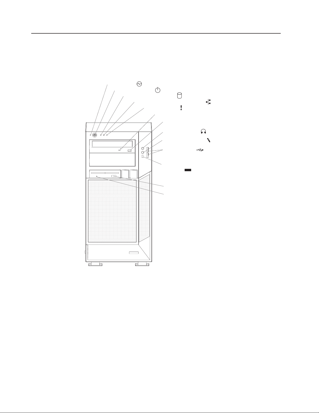
Controls, LEDs, and connectors
The following illustration shows the controls, LEDs, and front connectors on the
IntelliStation Z Pro Types 6223 and 6227 computers. See “Input/output connectors”
on page 53 for an illustration and description of the connectors on the rear of the
computer.
Power on LED
Power control button
Hard disk drive activity LED
Ethernet transmit/receive activity LED
System error LED
CD-ROM drive activity LED
CD-eject button
Line-out connector
Microphone connector
USB connectors
Power-on LED
When this LED is lit and not flashing, it indicates that the computer is
turned on. When this LED is flashing, it indicates that the computer is off
and still connected to an ac power source (standby mode).
Power-control button
Press this button to turn the computer on or off.
IEEE 1394A (FireWire)
connector
Diskette eject button
Diskette drive activity LED
1394
Hard disk drive activity LED
When this LED is lit, it indicates that the hard disk drive is in use.
Ethernet transmit/receive activity LED
When this LED is flickering, it indicates that there is activity between the
computer and the network. There are two of these LEDs, one on the front
and one on the rear of the computer.
Ethernet link status LED
When this LED is lit, it indicates that there is an active connection on the
Ethernet port. This LED is located on the rear of the computer.
6 IntelliStation Z Pro Types 6223 and 6227: Hardware Maintenance Manual and Troubleshooting Guide
Page 17

System-error LED
When this amber LED is lit, it indicates that a system error has occurred.
An LED on the system board is also lit to help isolate the error.
CD-ROM drive activity LED
When this LED is lit, it indicates that the CD-ROM drive is in use.
CD-eject button
Press this button to insert a CD into or remove a CD from the CD-ROM
drive.
Line out connector (green)
Use this connector to send audio signals from the computer to external
devices, such as speakers with built-in amplifiers, headphones, multimedia
keyboards, or the audio line-in jack on a stereo system.
Mic connector (pink)
Use this connector to connect a microphone to your computer when you
want to record voices or other sounds on the hard disk. You can also use
this connector (and a microphone) with speech recognition software.
USB connectors
Use these connectors to connect USB devices to your computer, using
redundant Plug and Play technology.
IEEE 1394A (FireWire) connectors
Use these connectors (four-pin on the front and six-pin on the rear) to
connect FireWire devices, such as digital video cameras and external hard
disk drives.
Diskette-eject button
Press this button to release a diskette from the diskette drive.
Diskette drive activity LED
When this LED is lit, it indicates that the diskette drive is in use.
Chapter 1. Introduction 7
Page 18

Turning on the computer
Note: When you connect the power cord to the computer and an ac power source,
the power-supply fan will run and continue to run when the computer is in
standby mode to provide cooling to the power supply.
When the computer is connected to an ac power source but is not turned on, the
operating system does not run, and all core logic is shut down; however, the
computer can respond to remote requests to turn on the computer. The power-on
LED flashes to indicate that the computer is connected to an ac power source but is
not turned on.
Notes:
1. Turn on all external devices, such as the monitor, before turning on the
computer.
2. The power-on LED on the front of the computer is lit when the computer is on
and while it is being turned on.
Approximately 20 seconds after the computer is connected to ac power, the
power-control button becomes active, and you can turn on the computer and start
the operating system by pressing the power-control button. The computer can also
be turned on in any of the following ways:
v If a power failure occurs while the computer is turned on, the computer will
restart automatically when power is restored.
v When you connect the computer to power for the first time, the Wake on LAN
feature can turn on the computer. If the computer was previously turned on, it
must be turned off correctly for the Wake on LAN feature to turn on the
computer.
What you see and hear when you start the computer depends on the features that
are installed and the settings in the Configuration/Setup Utility program.
If the power-on self-test (POST) detects a problem, there might be a series of
beeps or no beep, and a numeric error message might appear on the screen. Write
down any beep series and error code numbers with descriptions, and then see
Chapter 6, “Symptom-to-FRU index,” on page 83 for an explanation of the error
codes.
8 IntelliStation Z Pro Types 6223 and 6227: Hardware Maintenance Manual and Troubleshooting Guide
Page 19

Turning off the computer
Note: When you connect the power cord to the computer and an ac power source,
the power-supply fan will run and continue to run when the computer is in
standby mode to provide cooling to the power supply.
When you turn off the computer and leave it connected to ac power, the computer
can respond to requests, such as a remote request to turn on the computer. To
remove all power from the computer, you must disconnect it from the power source.
Some operating systems require an orderly shutdown before you turn off the
computer. See your operating-system documentation for information about shutting
down the operating system.
Chapter 1. Introduction 9
Page 20

Statement 5:
CAUTION:
The power control button on the device and the power switch on the power
supply do not turn off the electrical current supplied to the device. The device
also might have more than one power cord. To remove all electrical current
from the device, ensure that all power cords are disconnected from the power
source.
2
1
The computer can be turned off in any of the following ways:
v You can turn off the computer through the operating system. If this feature is
supported by your operating system, it will turn off the computer after performing
an orderly shutdown of the operating system.
If you are using the preinstalled Microsoft Windows XP operating system,
complete the following steps to shut down the operating system and computer:
1. Save and close all files that you are working with.
2. Close all open applications.
3. Click Start.
4. Click Turn Off Computer; then, click Turn Off to confirm.
If you are using the preinstalled Red Hat Linux operating system, complete the
following steps to shut down the operating system and computer:
1. Save and close all files with which you are working.
2. Close all open applications.
3. Click Red Hat Linux Main Menu Button → Logout → Shutdown.
4. Click OK to confirm.
v You can press the power-control button on the front of the computer. It will turn
off the computer after performing an orderly shutdown of the operating system, if
this feature is supported by your operating system.
Note: After turning off the computer, wait at least 5 seconds before you press
the power-control button to turn on the computer again.
v You can press and hold the power-control button for more than 4 seconds to
cause an immediate shutdown of the computer. You can use this feature to turn
off the computer if the operating system stops functioning.
10 IntelliStation Z Pro Types 6223 and 6227: Hardware Maintenance Manual and Troubleshooting Guide
Page 21

Chapter 2. Configuring the computer
Detailed information about configuring the computer is in the IBM IntelliStation Z
Pro User’s Guide on the IBM Documentation CD.
The latest information about these programs and the most recent device-driver files
are available at http://www.ibm.com/support.
The following configuration programs are available to configure your computer:
v Configuration/Setup Utility program
The Configuration/Setup Utility program is part of the basic input/output system
(BIOS) code in your computer. You can use this program to configure serial- and
parallel-connector assignments, change interrupt request (IRQ) settings, change
the drive startup sequence, set the date and time, and set passwords, and set
the chassis-intrusion detector. For more information on how to start this utility,
see “Starting the Configuration/Setup Utility program” on page 12. For detailed
information, see the User’s Guide.
v Boot Menu program
The Boot Menu program is part of the BIOS code in your computer. Use it to
temporarily assign a device to be first in the startup sequence, overriding the
startup sequence that is set in the Configuration/Setup Utility program.
v Broadcom NetXtreme Gigabit Ethernet Boot Agent
The Broadcom NetXtreme Gigabit Ethernet Boot Agent is part of the BIOS code
in your computer. You can use it to configure the network as a startable device,
and you can customize where the network startup option appears in your startup
sequence. You enable and disable the Broadcom NetXtreme Gigabit Ethernet
Boot Agent from the Configuration/Setup Utility program.
®
v Adaptec
– Adaptec RAID Configuration Utility programs (for Serial ATA RAID)
Use the Array Configuration Utility within the Adaptec RAID Configuration
Utility programs to configure the integrated Serial ATA (SATA) controller with
integrated RAID and the devices that are attached to it.
– SCSISelect Utility program (for SCSI RAID)
Use the SCSI HostRAID feature of the SCSISelect Utility program to configure
the integrated SCSI controller with integrated RAID and the devices that are
attached to it.
v ServeRAID Manager
ServeRAID Manager is available as a stand-alone program and as an IBM
Director extension. If a ServeRAID controller is installed in your computer, use
ServeRAID Manager to define and configure your disk-array subsystem before
you install your operating system.
v Ethernet controller configuration
Use this selection to configure the integrated Gigabit Ethernet controller, see
v SCSISelect Utility program (some models)
If your computer has a SCSI adapter installed, you can configure the devices that
are connected to the optional SCSI adapter. Use this program to change default
values, resolve configuration conflicts, and perform a low-level format on a SCSI
hard disk drive.
HostRAID™configuration programs
© Copyright IBM Corp. 2004, 2009 11
Page 22

Starting the Configuration/Setup Utility program
Complete the following steps to start the Configuration/Setup Utility program:
Note: When you use your computer for the first time, you might want to use the
Configuration/Setup Utility menu choice Load Default Settings to reset the
Configuration/Setup Utility menu choices to the factory default settings, in
case they were changed before you received the computer. Otherwise, some
choices might not appear in the list of menu choices.
1. Turn on the computer and watch the monitor screen. If the computer is already
on when you start this procedure, you must shut down the operating system,
turn off the computer, wait a few seconds until all in-use LEDs are turned off,
and restart the computer.
2. When the message Press F1 for Configuration/Setup appears on the screen
during startup, press F1. (This prompt appears on the screen for only a few
seconds. You must press F1 quickly.) If you have set both a user password and
an administrator password, you must type the administrator password to access
the full Configuration/Setup Utility menu.
3. Follow the instructions on the screen.
12 IntelliStation Z Pro Types 6223 and 6227: Hardware Maintenance Manual and Troubleshooting Guide
Page 23

Chapter 3. Diagnostics
This chapter provides basic troubleshooting information to help solve some common
problems that might occur with the computer.
If you cannot locate and correct the problem using the information in this section,
see Appendix A, “Getting help and technical assistance,” on page 125 for more
information.
General checkout
Follow the checkout procedure for diagnosing hardware problems. Review the
following information before performing the checkout procedure:
v Read Appendix B, “Safety information,” on page 127.
v The computer diagnostic programs are stored on the IBM Enhanced Diagnostics
CD. These programs provide the primary methods of testing the major
components of the computer. If you are not sure whether a problem is caused by
the hardware or by the software, you can run the diagnostic programs to confirm
that the hardware is working correctly.
v When you run the diagnostic programs, a single problem might cause several
error messages. If you receive several error messages, correct the cause of the
first error message. The other error messages might not occur the next time you
run the diagnostic programs.
v Before running the diagnostic programs, you must determine whether the failing
computer is part of a shared hard disk drive cluster (two or more servers sharing
external storage devices). If you suspect that it is part of a cluster, you can run
all diagnostic programs except the ones that test the storage unit (that is, a hard
disk drive in the storage unit) or the storage adapter that is attached to the
storage unit. The failing server might be part of a cluster if any of the following
conditions is true:
– The customer identifies the failing server as part of a cluster.
– One or more external storage units are attached to the failing server and at
least one of the attached storage units is also attached to another server or
unidentifiable device.
– One or more servers are located near the failing server.
v Important:
1. For servers that are part of a shared hard disk drive cluster, run one test at a
time. Do not run any suite of tests, such as “quick” or “normal” tests, because
this could enable the hard disk drive diagnostic tests.
2. If more than one error code is displayed, correct the first error. The other
error codes might not occur the next time you run the diagnostic programs.
3. If the server is suspended and a POST error code is displayed, see “POST
error codes” on page 85.
4. If the server is suspended and no error message is displayed, see “Error
symptoms” on page 95 and “Undetermined problems” on page 113.
5. For information about power-supply problems, see “Power checkout” on page
22.
6. For intermittent problems, check the error log; see “Diagnostic programs and
error messages” on page 16.
© Copyright IBM Corp. 2004, 2009 13
Page 24

Complete the following steps to perform the checkout procedure:
001 IS THE SERVER PART OF A CLUSTER?
YES. Schedule maintenance for the system. Shut down all systems related
to the cluster. Run the storage test.
NO. Go to step 002.
002 IF THE SERVER IS NOT PART OF A CLUSTER:
1. Turn off the server and all external devices.
2. Check all cables and power cords.
3. Set all display controls to the middle position.
4. Turn on all external devices.
5. Turn on the server.
6. Record any POST error messages that are displayed on the screen. If
an error is displayed, look up the first error in the “POST error codes”
on page 85.
7. Check the system-error log.
Note: The system-error log is available only with the Remote
Supervisor Adapter II.
If an error was recorded by the computer, see Chapter 6,
“Symptom-to-FRU index,” on page 83.
8. Start the diagnostic programs.
9. Check for the following responses:
v One beep
v Readable instructions or the main menu
003 DID YOU RECEIVE BOTH OF THE CORRECT RESPONSES?
NO. Find the failure symptom in Chapter 6, “Symptom-to-FRU index,” on
page 83.
YES. Run the diagnostic programs (see “Starting the diagnostic programs
and viewing the test log” on page 17).
If you receive an error, see Chapter 6, “Symptom-to-FRU index,” on page
83.
If the diagnostic programs were completed successfully and you still
suspect a problem, see “Undetermined problems” on page 113.
Diagnostic tools overview
The following tools are available to help you diagnose and solve hardware-related
problems:
v Computer Support flowchart
The Computer Support flowchart on the following page will help you determine
how to get help from IBM and register your computer.
v POST beep codes and error messages
The power-on self-test generates beep codes and messages to indicate
successful test completion or the detection of a problem. See “Power-on self-test
(POST)” on page 15 for more information. Additional information is recorded in
the post error logs.
14 IntelliStation Z Pro Types 6223 and 6227: Hardware Maintenance Manual and Troubleshooting Guide
Page 25

v Diagnostic programs
The system diagnostic programs are on a hidden partition on the hard disk.
These programs are the primary methods of testing the major components of
your computer. See “Diagnostic programs and error messages” on page 16 for
more information.
v Symptom-to-FRU index
This index problem symptoms and steps to correct each problem. See the
Chapter 6, “Symptom-to-FRU index,” on page 83 for more information.
v System-board error LEDs
An LED on the system board might also be lit to help isolate an error indicated
by the system error LED on the front of the computer. See “System board error
LEDs” on page 74 for more information.
Power-on self-test (POST)
When you turn on the computer, the power-on self-test (POST) performs a series of
tests to check the operation of system components and some of the installed
options.
If POST finishes without detecting any problems, the first window of your operating
system or application program opens.
If POST detects a problem, more than one beep sounds and an error message
appears on the screen.
Notes:
1. If you have set a user password, you must type the password and press Enter,
2. A single problem might cause several error messages. When this occurs, work
POST beep codes
Use the following beep code descriptions to help diagnose and solve problems that
are detected during startup:
No beeps
Continuous beep
Beep codes for specific failures
when prompted, before the operating system will start.
to correct the cause of the first error message. After you correct the cause of
the first error message, the other error messages usually will be resolved the
next time you run the test.
If no beep occurs after the computer completes POST, see Chapter 6,
“Symptom-to-FRU index,” on page 83.
The startup (boot) microprocessor has failed, or the system board or
speaker subsystem might contain a failing component. If the computer
continues through POST with no errors, got to “General checkout” on page
13 and run the diagnostic programs. If no video appears, the startup
processor has failed.
Beep codes indicating specific system problems. For a list of beep codes,
see “Beep symptoms” on page 83.
Chapter 3. Diagnostics 15
Page 26

POST error messages
POST error messages can appear when a problem is detected during startup. For a
complete list of POST messages, see “POST error codes” on page 85.
Diagnostic programs and error messages
Note: When using diagnostics with a USB keyboard and mouse attached, you
must first enable USB emulation. Complete the following steps to enable
USB emulation:
1. Restart the computer and press F1 to start the Configuration/Setup
Utility.
2. Select Devices and I/O Ports.
3. Select USB Setup.
4. Make sure that the USB keyboard and mouse are enabled.
Diagnostic error messages indicate that there is a problem; they are not intended to
be used to identify a failing part. Troubleshooting and servicing complex problems
that are indicated by error messages must be performed by trained service
personnel.
Sometimes the first error to occur causes additional errors. In this case, the
computer displays more than one error message. Always follow the suggested
action instructions for the first error message that appears.
Text messages
The diagnostic text message format is as follows:
result test_specific_string
where:
result is one of the following results:
Passed
This test was completed without any errors.
Failed This test discovered an error.
User Aborted
You stopped the test before it was completed.
Not Applicable
You attempted to test a device that is not present in the computer.
Aborted
The test could not proceed because of the computer configuration.
Warning
A possible problem was reported during the test (for example, a
device that was to be tested is not installed).
test_specific_string
is an error code or other information about the error.
16 IntelliStation Z Pro Types 6223 and 6227: Hardware Maintenance Manual and Troubleshooting Guide
Page 27

Starting the diagnostic programs and viewing the test log
The IBM Enhanced Diagnostics programs isolate problems from the computer
hardware and software. The programs run independently of the operating system.
This method of testing is generally used when other methods are not accessible or
have not been successful in isolating a problem suspected to be hardware related.
Complete the following steps to view the test log.
Note: If you are already running the Enhanced Diagnostics program, begin with
step 4.
1. Start the Enhanced Diagnostics programs.
v To start the Enhanced Diagnostics programs in a Windows operating system,
complete the following steps:
a. Restart the computer and when the message To start the Product
Recovery program is displayed, quickly press F11.
b. Select System utilities.
c. Select Run diagnostics to start the diagnostics programs.
v To start the Enhanced Diagnostics programs in Red Hat Linux operating
system, complete the following steps:
a. Restart the computer.
b. When the operating system selection menu is displayed, select IBM
Preload Recovery & Diagnostics.
c. Select Run diagnostics to start the diagnostics programs.
(Optionally, insert the IBM Enhanced Diagnostics diskette and restart the
computer.)
2. Run the applicable diagnostics program and when the Diagnostic Programs
screen appears, select Utility.
3. Select View Test Log from the list; then, follow the instructions on the screen.
The test log records data about system failures and other pertinent information.
The test log will not contain any information until after the diagnostic program
has run.
4. Save the test log to a file on a diskette or to your hard disk.
Notes:
a. To save the test log to a diskette, you must use a diskette that you have
formatted yourself; this function does not work with preformatted diskettes. If
the diskette has sufficient space for the test log, the diskette can contain
other data.
b. The system maintains the test-log data only while the Enhanced Diagnostics
program is running. When you end the Enhanced Diagnostics program, the
test log is cleared.
For a complete list of diagnostic error messages, see “Diagnostic error codes” on
page 90.
Small computer system interface (SCSI) messages
If you receive a SCSI error message when running the SCSISelect Utility program,
it might be the result of any of the following problems:
v A failing SCSI device (adapter or drive)
v An incorrect SCSI configuration
Chapter 3. Diagnostics 17
Page 28

v Duplicate SCSI IDs in the same SCSI chain
v An incorrectly installed SCSI terminator
v A defective SCSI terminator
v An incorrectly installed cable
v A defective cable
To solve the problem, make sure that:
v The external SCSI devices are turned on. External SCSI devices must be turned
on before the computer.
v The cables for all external SCSI devices are connected correctly.
v The last device in each SCSI chain is terminated correctly.
v The SCSI devices are configured correctly.
If the problem remains, run the diagnostic programs to obtain additional information
about the failing device.
Note: If the computer does not have a SCSI hard disk drive, ignore any message
that indicates that the BIOS code is not installed.
PC-Doctor for Windows
Your computer contains PC-Doctor for Windows, which is designed specifically for
the Windows operating environment. Because these diagnostics work with the
operating system, they test hardware and analyze certain software components.
These diagnostic programs are especially useful for isolating operating-system and
device-driver problems.
Complete the following steps to use PC-Doctor for Windows:
1. On the Windows desktop, click Start → All Programs → PC-Doctor.
2. Follow the instructions on the screen. Help is available online.
Updating (flash-updating) the BIOS code on the computer
Periodically, IBM might post new levels of BIOS code on the Web. Always check the
IBM Support Web site at http://www.ibm.com/support for the latest level of BIOS
code, device drivers, documentation, and hints and tips. You can use one of the
following methods to update (flash) the BIOS code on the computer:
v Download the BIOS code update file directly to the hard disk.
v Download the BIOS code update file to a diskette (attach an external Universal
Serial Bus [USB] portable diskette drive if you have not installed an integrated
diskette drive); then, update the BIOS code on the computer.
You can order an optional IBM USB Portable Diskette Drive such as part number
05K9276. For a list of supported options for your computer, go to
http://www.ibm.com/pc/compat/.
v Download the BIOS code update file to a CD using a writable optional device
(CD-RW drive); then, start the computer with the CD in the CD-ROM drive to
update the BIOS code on the computer.
One file is available for each method. The description next to each file indicates the
type of medium to which you can download the file. A readme file is available with
instructions for installing the BIOS code update.
18 IntelliStation Z Pro Types 6223 and 6227: Hardware Maintenance Manual and Troubleshooting Guide
Page 29

Complete the following steps to download the BIOS (flash) update files:
1. http://www.ibm.com/support.
2. In the Downloads category, click Downloads & drivers.
3. In the Brand field, select IntelliStation.
4. In the Family field, select IntelliStation Z Pro.
5. In the Type field, select 6223 and click Continue.
6. In the Filter by category field, select BIOS (system).
7. Scroll down and select the applicable file for your operating system.
8. Select the file for the type of medium you want to use; then, download the file
and install it.
9. Restart the computer.
See the readme file for additional information about how to install the image files.
Note: Always reset the Configuration/Setup Utility program to the default values
after updating the BIOS code.
Recovering from a POST/BIOS update failure
Notes:
1. You can download a file to create the POST/BIOS recovery diskette or CD from
http://www.ibm.com/support on the World Wide Web. For more information, see
Appendix A, “Getting help and technical assistance,” on page 125.
2. To create and use a diskette, you must add a diskette drive to your computer.
To enable a USB diskette drive, follow these steps:
a. Enable the Legacy USB Support option under the Startup Option menu
choice in the Configuration/Setup Utility program.
b. Set your removable media device as the first startup device.
c. Select the removable media device you want to boot from and move it to the
top of the Removable Devices list.
If power to your computer is interrupted while POST/BIOS code is being updated
(flash update), the computer might not restart (reboot) correctly or might not display
video (no video). If this happens, complete the following steps:
1. Review the safety information beginning on page 127 and “Handling
static-sensitive devices” on page 23.
2. Turn off the computer and all attached devices.
3. Disconnect the power cord.
4. Remove the cover and support bracket.
5. Locate the boot block recovery jumper (JCON1) on the system board. The
following illustration shows the location of the boot block jumper on the system
board.
Chapter 3. Diagnostics 19
Page 30
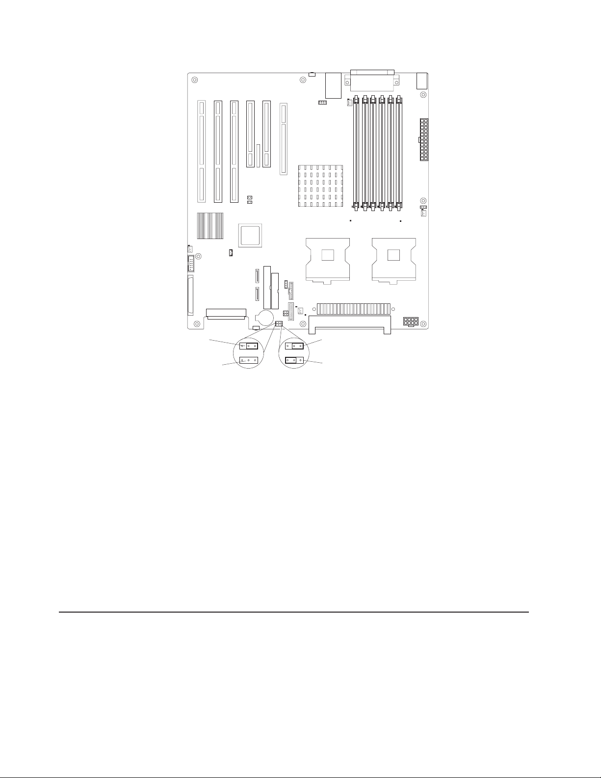
Default
(pins 1 and 2)
BIOS crisis
recovery
(no jumper)
3 2 1 3 2 1
(JCON1)
CMOS
(JCMOS1)
data
Default
(pins 1 and 2)
Clear CMOS data
(pins 2 and 3)
6. Remove the boot block recovery jumper from pins 1 and 2.
7. Replace any adapters that were removed; then, replace the support bracket
and replace the cover.
8. Connect the computer to a power source, keyboard, monitor, and mouse.
9. Insert the POST/BIOS update (flash) recovery diskette or CD into the diskette
drive or CD-ROM drive.
10. Turn on the computer and the monitor.
11. After the update session is completed, turn off the computer and monitor.
12. Remove the diskette or CD from the diskette drive or CD-ROM drive.
13. Disconnect all power cords; then, remove the computer cover.
14. Return the boot block recovery jumper to pins 1 and 2.
15. Replace the computer cover; then, reconnect all external cables and power
cords and turn on the peripheral devices.
16. Turn on the computer to restart the operating system.
Erasing a lost or forgotten password (clearing CMOS)
This section applies to lost or forgotten passwords. More information about lost or
forgotten passwords is available in Access IBM.
Complete the following steps to set the CMOS recovery jumper and erase a
forgotten password:
1. Review the safety information beginning on page 127 and “Handling
static-sensitive devices” on page 23.
20 IntelliStation Z Pro Types 6223 and 6227: Hardware Maintenance Manual and Troubleshooting Guide
Page 31

2. Turn off the computer and all attached devices.
3. Disconnect the power cord.
4. Remove the side cover and support bracket.
5. Locate the CMOS recovery jumper (JCMOS1) on the system board, removing
any adapters that impede access to the jumper. An illustration showing the
location of the jumper on the system board is in “Recovering from a
POST/BIOS update failure” on page 19.
6. Move the CMOS recovery jumper from pins 1 and 2 to pins 2 and 3.
7. Wait 60 seconds; then, return the CMOS recovery jumper to pins 1 and 2.
8. Replace any adapters that were removed; then, replace the support bracket
and replace the side cover.
You can now start the computer one time, and start the Configuration/Setup
Utility program, without having to use the power-on password. At this time, you
can either delete the old password or set a new user password. If you do not
change or delete the password, the next time you start the computer the
original user password will be reinstated.
9. Connect the computer to a power source, keyboard, monitor, and mouse.
10. Turn on the computer. The Configuration/Setup Utility program starts.
11. Follow the instructions to erase the existing password or create a new
password.
12. Select Save Settings and press Enter.
Replacing the battery
When replacing the battery, you must replace it with a lithium battery of the same
type from the same manufacturer. To avoid possible danger, read and follow the
information in Appendix B, “Safety information,” on page 127.
To order replacement batteries, call 1-800-426-7378 within the United States, and
1-800-465-7999 or 1-800-465-6666 within Canada. Outside the U.S. and Canada,
call your IBM marketing representative or authorized reseller.
Note: After you replace the battery, you must reconfigure the computer and reset
the system date and time.
Complete the following steps to replace the battery:
1. Review the safety information beginning on page 127 “Installation guidelines” on
page 23, and “Handling static-sensitive devices” on page 23..
2. Follow any special handling and installation instructions that come with the
replacement battery.
3. Turn off the computer and all attached devices. Disconnect all external cables
and power cords; then, remove the computer cover and the support bracket.
(See “Removing the side cover” on page 25)
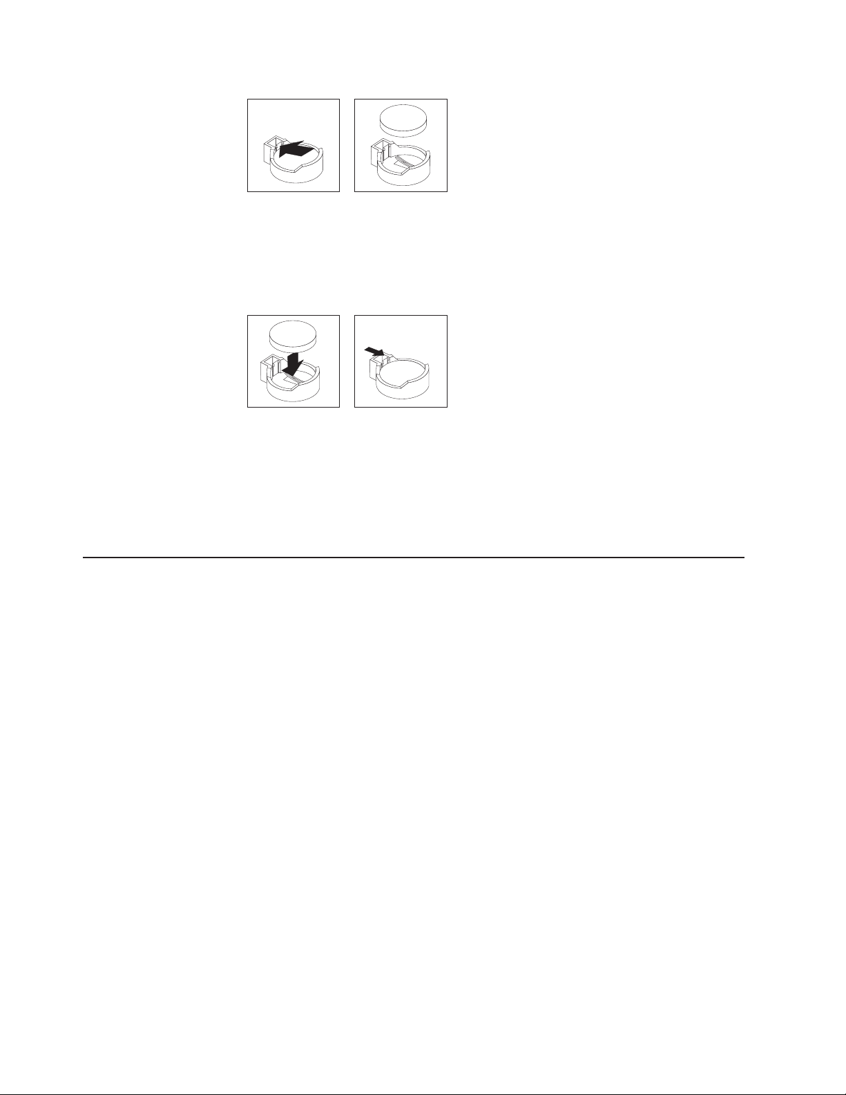
4. Remove the battery:
a. Use a fingernail to press the top of the battery clip away from the battery.
The battery pops up when released.
b. Use your thumb and index finger to lift the battery from the socket.
Chapter 3. Diagnostics 21
Page 32
Power checkout
5. Insert the new battery:
a. Tilt the battery so that you can insert it into the socket on the side opposite
the battery clip.
b. Press the battery down into the socket until it clicks into place. Make sure
that the battery clip holds the battery securely.
6. Replace the cover and connect the cables.
7. Turn on the computer.
8. Start the Configuration/Setup Utility program and set configuration parameters.
v Set the system date and time.
v Set passwords if necessary.
v Save the configuration.
Power problems can be difficult to solve. For example, a short circuit can exist
anywhere on any of the power-distribution buses. Usually, a short circuit will cause
the power subsystem to shut down because of an overcurrent condition.
A general procedure for troubleshooting power problems is as follows:
1. Turn off the server, and disconnect all ac power cords.
2. Check for loose cables in the power subsystem. Also check for short circuits, for
example, if there is a loose screw causing a short circuit on a circuit board.
3. Remove adapters and disconnect the cables and power connectors to all
internal and external devices until the server is at the minimum configuration
required to start the server (see, “Minimum operating requirements” on page
113).
4. Reconnect all ac power cords and turn on the server. If the server starts
successfully, replace adapters and devices one at a time until the problem is
isolated. If the server does not start from the minimal configuration, replace
FRUs of the minimal configuration one at a time until the problem is isolated.
To use this method, you must know the minimum configuration that is required for
the server to start (see page 103).
22 IntelliStation Z Pro Types 6223 and 6227: Hardware Maintenance Manual and Troubleshooting Guide
Page 33

Chapter 4. Installing options
This chapter provides instructions for installing or replacing hardware options in
your computer. For a list of supported options for your computer, go to
http://www.ibm.com/pc/; then, select your country and navigate to the list of options
for your computer.
Installation guidelines
Before you begin installing options in your computer, read the following information:
v Read the safety information beginning on page 127 and the guidelines in
“Handling electrostatic discharge-sensitive devices” on page 130.. This
information will help you work safely with your computer and options.
v Make sure that you have an adequate number of properly grounded electrical
outlets for your computer, monitor, and other devices that you will connect to the
computer.
v Back up all important data before you make changes to disk drives.
v Have a small flat-blade screwdriver available.
v When you need to access the inside of the computer to install options, you might
find it easier to lay the computer on its side.
v Blue on a component indicates touch points, where you can grip the component
to remove it from or install it in the computer, open or close a latch, and so on.
System reliability considerations
To help ensure proper cooling and system reliability, make sure that:
v Each of the drive bays has a drive or a filler panel and electromagnetic
compatibility (EMC) shield installed in it.
v There is adequate space around the computer to allow the computer cooling
system to work properly. Leave approximately 50 mm (2 in.) of open space
around the front and rear of the computer. Do not place objects in front of the
fans. For proper cooling and airflow, replace the computer cover before turning
on the computer. Operating the computer for extended periods of time (more
than 30 minutes) with the computer cover removed might damage computer
components.
v You have followed the cabling instructions that come with optional adapters.
v You have replaced a failed fan as soon as possible.
Handling static-sensitive devices
Attention: Static electricity can damage electronic devices and your computer. To
avoid damage, keep static-sensitive devices in their static-protective packages until
you are ready to install them.
To reduce the possibility of damage from electrostatic discharge, observe the
following precautions:
v Limit your movement. Movement can cause static electricity to build up around
you.
v Handle the device carefully, holding it by its edges or its frame.
v Do not touch solder joints, pins, or exposed circuitry.
v Do not leave the device where others can handle and damage it.
© Copyright IBM Corp. 2004, 2009 23
Page 34
v While the device is still in its static-protective package, touch it to an unpainted
metal part of the computer for at least 2 seconds. This drains static electricity
from the package and from your body.
v Remove the device from its package and install it directly into the computer
without setting down the device. If it is necessary to set down the device, put it
back into its static-protective package. Do not place the device on your computer
cover or on a metal surface.
v Take additional care when handling devices during cold weather. Heating reduces
indoor humidity and increases static electricity.
Installing options in your computer
This section provides instructions for installing hardware options in your computer.
Note: To remove the side cover and install options, you might find it easier to lay
the computer on its side.
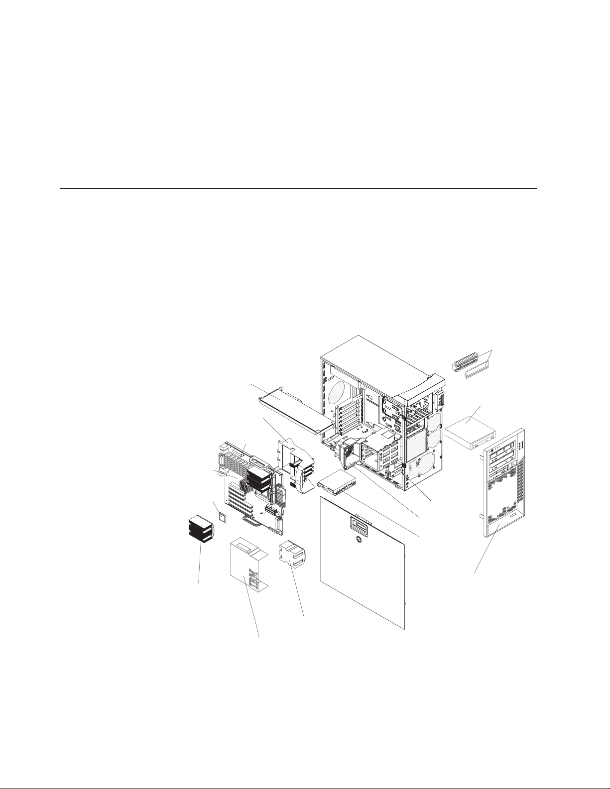
Major components of your computer
The following illustration shows the major components in the Z Pro Type 6223
computer.
EMC shields
Adapter retaining
bracket
System
board
Microprocessor
Heat-sink
PCI card
CD-ROM drive
DIMMs
Drive cage
Fan assembly
Hard disk
drive
Bezel
Microprocessor
baffle assembly
Microprocessor
air baffle
24 IntelliStation Z Pro Types 6223 and 6227: Hardware Maintenance Manual and Troubleshooting Guide
Page 35
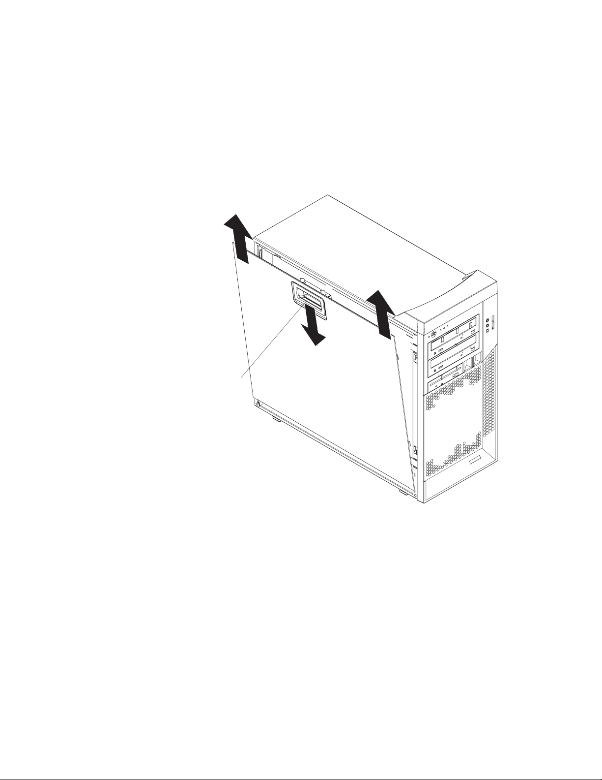
Removing the side cover
To remove the cover, you might find it easier to lay the computer on its side.
Complete the following steps to remove the side cover of the computer:
1. Review the “Installation guidelines” on page 23.
2. Turn off the computer and all attached devices (see “Turning off the computer”
on page 9); then, disconnect all power cords and external cables.
3. Pull down on the cover-release handle; then, pull the cover straight up and lift
the side cover off the computer and set it aside.
Cove-release
handle
To replace the side cover, see “Replacing the side cover” on page 51.
Attention: For proper cooling and airflow, replace the side cover before turning on
the computer. Operating the computer with the cover removed might damage
computer components.
Chapter 4. Installing options 25
Page 36
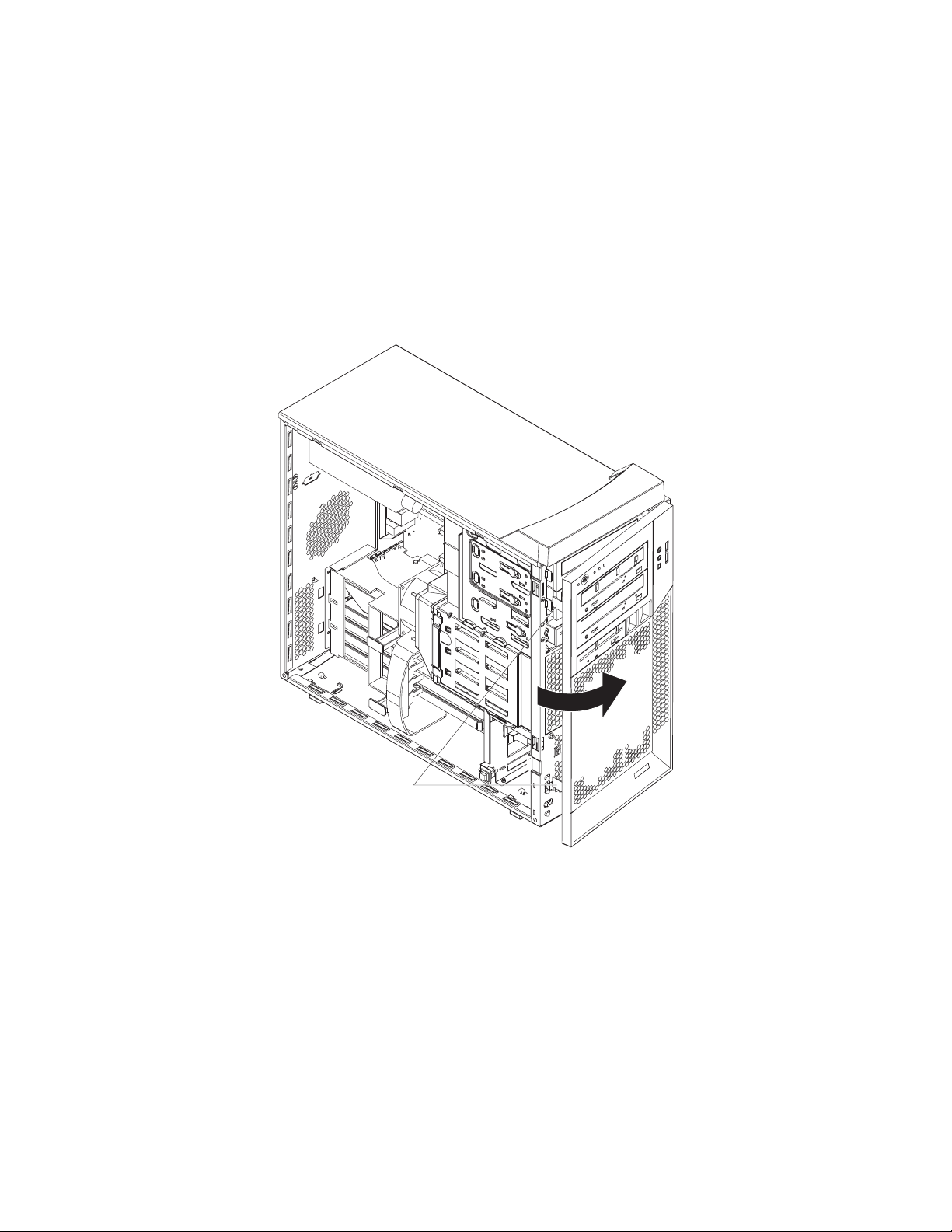
Removing the bezel
When working with some devices, such as additional optical drives, you must first
remove the bezel to access the device. To install or remove options, you might find
it easier to lay the computer on its side.
Complete the following steps to remove the bezel:
1. Unlock the side-cover lock.
2. Remove the side cover (see “Removing the side cover” on page 25).
3. Locate the two bezel clips that are securing the bezel to the computer chassis.
Gently lift and hold the bezel clips up and at the same time, rotate the bezel
outward to disengage it from the side tabs; then, set the bezel aside.
Bezel clips
For instructions for replacing the bezel, see “Replacing the bezel” on page 50.
Installing an adapter
The following notes describe the types of adapters that your computer supports and
other information that you must consider when installing an adapter. See “System
board option connectors” on page 71 for an illustration of the adapter slot locations.
v Read the documentation that comes with your operating system.
v Locate the documentation that comes with the adapter and follow those
instructions in addition to the instructions in this chapter. If you need to change
the switch or jumper settings on your adapter, follow the instructions that come
with the adapter.
26 IntelliStation Z Pro Types 6223 and 6227: Hardware Maintenance Manual and Troubleshooting Guide
Page 37

v Your computer comes with adapter connectors or slots. The video adapter is
installed in the PCI Express x16 slot (slot 1). You can install up to five additional
adapters in your computer in PCI slots 2 and 3, and PCI-X slots 4, 5, and 6.
v You can install full-length adapters in PCI slot 3, and PCI-X slots 4, 5, and 6.
However, a full-length adapter will not fit in PCI slot 2 and is not supported. None
of the expansion slots are hot-plug slots.
v Your computer supports 5.0 V signaling and universal PCI 32-bit/33 MHz
adapters in PCI slots 2 and 3.
v Your computer supports 3.3 V signaling and universal PCI-X 64-bit/133 MHz
adapters in PCI-X slot 4.
v Your computer supports 3.3 V signaling and universal PCI-X 64-bit/100 MHz
adapters in PCI-X slot 5 and 6.
v Your computer uses a rotational interrupt technique to configure PCI adapters,
which means that you can install a variety of PCI adapters that currently do not
support sharing of PCI interrupts.
v If you install a ServeRAID 6i+ adapter, it must be installed in PCI-X slot 5.
v If you install an optional RAID adapter in your computer, you must reinstall the
operating system and applications that came preinstalled on your computer.
v The system scans the PCI Express x16 slot (slot 1), PCI expansion slots 2 and
3, and PCI-X expansion slots 4 through 6 to assign system resources. Then, it
starts the PCI devices in the following order, if you have not changed the default
startup sequence: PCI Express x16 slot (slot 1), system-board integrated drive
electronics (IDE), Serial ATA (SATA), or small computer system interface (SCSI)
devices (including optional ServeRAID-6i+ controller), and then PCI-X slots 4
through 6.
v For a list of supported options for your computer, go to http://www.ibm.com/pc/;
then, select your country and navigate to the list of options for your computer.
Complete the following steps to install an adapter in your computer:
1. Read the safety information beginning on page 127 and the guidelines in
“Handling static-sensitive devices” on page 23
2. Turn off the computer and all attached devices (see “Turning off the computer”
on page 9); then, disconnect all external cables and power cords.
3. Remove the side cover (see “Removing the side cover” on page 25).
4. Determine the slot in which you want to install the adapter. Review the
instructions that come with the adapter for any requirements, restrictions, or
cabling instructions. It might be easier to route any cables before you install
the adapter.
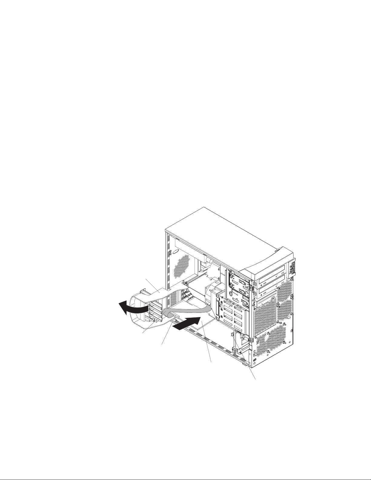
5. For full-length adapters, rotate the rear adapter-retention bracket to the open
(unlocked) position (you might have to first remove any adapters that might be
in the way). Press down on the bottom tab of the front adapter-retention
bracket to release it (the tab is inside the fan compartment that is next to the
front adapter-retention bracket). If you are installing a smaller adapter, rotate
only the rear adapter-retention bracket.
Chapter 4. Installing options 27
Page 38
6. Remove the expansion-slot cover. From the rear of the computer, press on the
slot cover. Grasp it and pull it out of the expansion slot. Store it in a safe place
for future use.
Attention: Expansion-slot covers must be installed on all empty slots. This
maintains the electronic emissions standards of the computer and ensures
proper ventilation of computer components.
7. Follow the instructions that come with the adapter to set jumpers or switches, if
any.
Attention: Avoid touching the components and gold-edge connectors on the
adapter.
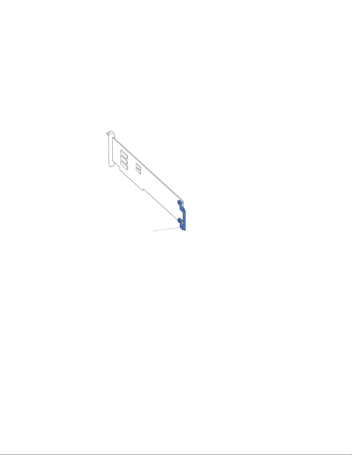
8. If you are installing a full-length adapter, remove the blue adapter guide (if any)
from the end of the adapter.
Adapter guide
Attention: Be certain that the adapter is correctly seated in the expansion
slot before you turn on the computer. Incomplete installation of an adapter
might damage the system board or the adapter.
28 IntelliStation Z Pro Types 6223 and 6227: Hardware Maintenance Manual and Troubleshooting Guide
Page 39
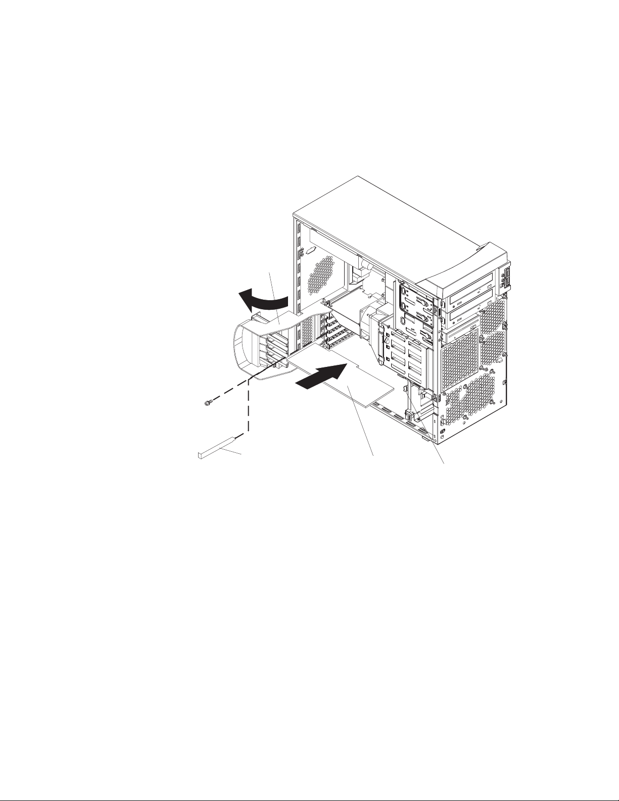
9. Carefully grasp the adapter by the top edge or upper corners and move the
adapter directly from the static-protective package to adapter slot (avoid
touching the components and gold-edge connectors on the adapter). Align the
adapter with the expansion slot guides; then, press the adapter firmly into the
expansion slot.
Attention: Make sure that the adapter is correctly seated in the expansion
slot before you turn on the computer. Incomplete installation of an adapter
might damage the system board or the adapter.
Rear adapter
retention bracket
Expansionslot cover
Adapter
Front adapter
retention bracket
10. Connect required cables to the adapter. Route cables so that they do not block
the flow of air from the fans. If you are installing an optional SCSI adapter, see
“Cabling an optional SCSI adapter” on page 30 for additional information.
11. If you have another adapter to install, repeat steps 4 through 10.
12. If you have installed a full-length adapter, press down on the top tab of the
front adapter-retention bracket to lock it in place (the tab is inside the fan
compartment that is next to the front adapter-retention bracket).
Note: If any adapter in your computer is large or has heavy cables attached to
it, you can secure the adapter with a screw. Insert one backup
expansion-slot screw (the screws are stored directly above the front
adapter-retention bracket) through the top of each adapter bracket into
the screw hole and secure the adapter before proceeding to the next
step.
13. If you have other options to install, do so now; otherwise, replace the side
cover (see “Replacing the side cover” on page 51), reconnect the external
cables and power cords, and turn on the computer.
Chapter 4. Installing options 29
Page 40
Cabling an optional SCSI adapter
You can install an optional SCSI adapter in your computer to control the internal
hard disk drives and provide additional RAID capabilities. With a SCSI adapter
installed, you can configure the internal hard disk drives into disk arrays. You can
also cable a SCSI adapter to external hard disk drives. See your SCSI adapter
option documentation for complete instructions for installing a SCSI adapter in your
computer and for additional information about SCSI adapters.
Notes:
1. The SCSI cables that are used by the integrated SCSI controller cannot be
used with an optional SCSI adapter.
2. If you install a ServeRAID 6i+ adapter, it must be installed in slot 5; no cabling
is required for this adapter.
Complete the following steps to cable an optional SCSI adapter:
1. Install the SCSI adapter (see “Installing an adapter” on page 26).
2. Connect the SCSI-signal cable to the adapter and one or more of the signal
cable connectors to the rear of the SCSI devices.
3. Connect the SCSI-activity-indicator cable to the adapter and to the SCSI-LED
connector on the system board. See “System board internal connectors” on
page 72 for the location of the SCSI-LED connector.
Rear adapter
retention bracket
SCSI signal
cable
SCSI signal
cable connector
SCSI adapter
4. Complete the installation of the optional SCSI adapter.
Front adapter
retention bracket
30 IntelliStation Z Pro Types 6223 and 6227: Hardware Maintenance Manual and Troubleshooting Guide
Page 41
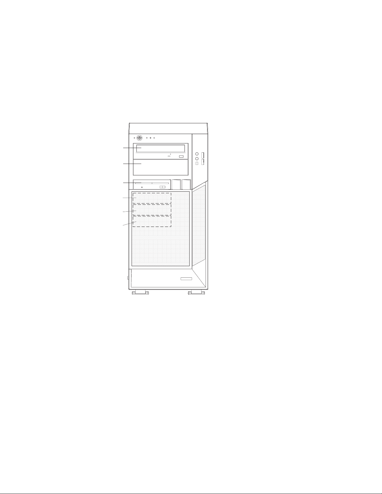
Installing a drive
Depending on your computer model, one or more of the following drives might be
installed in your computer:
v Diskette drive (optional)
v Hard disk drive
v CD-ROM, CD-RW, or DVD/CD-RW combo drive
Your Z Pro Type 6223 computer comes with an IDE CD-ROM drive in bay 1 and a
hard disk drive in bay 4.
Bay 1
Bay 2
Bay 3
Bay 4
Bay 5
Bay 6
The following notes describe the types of drives that your computer supports and
other information that you must consider when installing drives:
v Make sure that you have all the cables and other equipment specified in the
documentation that comes with the drive.
v Select the bay in which you want to install the drive.
v Check the instructions that come with the drive to see whether you need to set
any switches or jumpers on the drive. If you are installing a SCSI device, be sure
to set the SCSI ID for that device.
v You can install removable-media drives in bays 1, 2, and 3 only. Tape drives,
diskette drives, CD-ROM, DVD/CD-RW, and DVD-ROM drives are examples of
removable-media drives.
v You can install a 3.5-in. slim-high or 5.25-in. half-high removable-media drive,
such as a tape backup drive, in bay 2.
v You can install a diskette drive or a 3.5-in slim-high hard disk drive in bay 3.
v To install a 3.5-in. drive in a 5.25-in. bay, you must use the 5.25-in. conversion
kit.
v Your computer supports only one diskette drive: either a diskette drive in bay 3 or
a USB drive connected to the USB connector on the front of the computer.
Chapter 4. Installing options 31
Page 42

v Two Serial ATA hard disk drive connectors are on the system board.
v If you install SCSI hard disk drives and SATA hard disk drives in the same
computer, note the following HostRAID considerations for hard disk drives:
– You can enable HostRAID on only one subsystem (SCSI or SATA).
– If HostRAID is enabled on a subsystem, you can install boot hard disk drives
on that subsystem only.
If you fail to observe these restrictions, the computer will usually disable the
BIOS for the last subsystem loaded, which typically is SCSI.
For more information about HostRAID, see in the User’s Guide.
v The electromagnetic interference (EMI) integrity and cooling of the computer are
protected by having all bays, PCI, and PCI-X slots covered or occupied. When
you install a drive, PCI adapter, or PCI-X adapter, save the EMC shield and filler
panel from the bay or the adapter slot cover in the event you later remove the
drive or adapter.
v For a complete list of supported options for your computer, go to
http://www.ibm.com/pc/; then, select your country and navigate to the list of
options for your computer.
Installing a drive in bay 2 or 3
Complete the following steps to install a drive in bay 2 or 3:
1. Read the safety information beginning on page 127 and “Installation
guidelines” on page 23.
2. Turn off the computer and peripheral devices, and disconnect the power cords
and all external cables.
3. Remove the side cover (see “Removing the side cover” on page 25).
4. Remove the bezel (see “Removing the bezel” on page 26).
32 IntelliStation Z Pro Types 6223 and 6227: Hardware Maintenance Manual and Troubleshooting Guide
Page 43

5. Use a screwdriver to pry the filler panel and EMC shield away from the
computer.
EMC shield
Filler panel
Note: If you are installing a drive that contains a laser, observe the following
safety precaution.
Chapter 4. Installing options 33
Page 44

Statement 3
CAUTION:
When laser products (such as CD-ROMs, DVD drives, fiber optic devices, or
transmitters) are installed, note the following:
v Do not remove the covers. Removing the covers of the laser product could result in
exposure to hazardous laser radiation. There are no serviceable parts inside the
device.
v Use of controls or adjustments or performance of procedures other than those
specified herein might result in hazardous radiation exposure.
Danger
Some laser products contain an embedded Class 3A or Class 3B laser diode. Note the
following. Laser radiation when open. Do not stare into the beam, do not view directly with
optical instruments, and avoid direct exposure to the beam.
Class 1 Laser Product
Laser Klasse 1
Laser Klass 1
Luokan 1 Laserlaite
Appareil A Laser de Classe 1
`
6. Touch the static-protective package containing the drive to any unpainted metal
surface on the computer; then, remove the drive from the package and place it
on a static-protective surface.
7. Set any jumpers or switches on the drive according to the documentation that
comes with the drive.
Note: You might find it easier to install the new drive from the front and then
attach the cables.
34 IntelliStation Z Pro Types 6223 and 6227: Hardware Maintenance Manual and Troubleshooting Guide
Page 45

8. To install a drive in bay 2, complete the following steps:
a. Remove the large drive clip attached to the side of bay 2 of the drive cage
for bays 1, 2, and 3 (see the figure below). Slide the drive clip to the left to
disengage it from the drive cage; then, snap the drive clip into the screw
holes on the side of the drive.
Drive release tabs
Drive clip
b. If you are installing a 5.25-in. drive in bay 2, slide the drive into the drive
bay until it snaps in place. If you are installing a 3.5-in. drive in bay 2, you
must attach the 5.25-in. conversion kit, which you can order from IBM, to
the 3.5-in. drive.
c. Continue with step 10.
9. To install a drive in bay 3, use one of the following procedures:
Note: Only a 3.5-in. device can be installed in bay 3.
v If you are installing an external media device in bay 3, complete the
following steps:
a. Remove the small drive clip that is attached to the side of bay 3 of the
drive cage for bays 1, 2, and 3 (see the figure above). Slide the drive
clip to the left to disengage it from the drive cage; then, snap the drive
clip into the screw holes on the side of the drive.
b. Slide the drive into the drive bay until it snaps in place.
c. Continue with step 10.
v If you are installing a hard disk drive in bay 3, complete the following steps:
a. Push the drive into the bay from the rear of the drive cage; then, use the
two screws to attach the drive to the drive cage.
b. Continue with step 10.
Chapter 4. Installing options 35
Page 46

10. Determine whether the drive is an IDE or SCSI device; then, connect one end
of the applicable signal cable into the back of the drive and make sure that the
other end of this cable is connected into the applicable IDE or SCSI connector
on the system board.
11. Route the signal cable so that it does not block the airflow to the rear of the
drives or over the microprocessor and memory.
12. If you have another drive to install or remove, do so now.
13. Connect the power cable to the back of the drive. The connectors are keyed
and can be inserted only one way.
14. If you have other options to install or remove, do so now; otherwise, replace
the bezel (see “Replacing the bezel” on page 50) and replace the side cover
(see “Replacing the side cover” on page 51.
Installing a SCSI or SATA drive in bay 4, 5, or 6
Some models come with non-hot-swap SCSI hard disk drives or Serial ATA (SATA)
hard disk drives. Before you install a hard disk drive in bays 4, 5, and 6, read the
following information:
v Read the documentation that comes with the drive for cabling instructions.
v Route the cable before you install the drive. Do not block the airflow from the
fans.
v You can install up to four SCSI hard disk drives in your computer (SCSI models
only).
v Your computer supports up to two Serial ATA hard disk drives.
Note: Your computer can support a third and fourth SATA drive if you install an
optional ServeRAID-7t S-ATA controller. In addition, if you install the
optional ServeRAID-7t S-ATA controller to add a third and fourth drive, all
four SATA drives must then be connected to the ServeRAID-7t S-ATA
controller instead of the system board. See the optional ServeRAID-7t
S-ATA controller documentation for cabling instructions.
If you purchase a new SATA hard drive, you will also need to purchase a
signal cable for it. IBM SATA hard drive option comes with a signal cable.
v Install hard disk drives in this sequence: bay 4, bay 5, bay 6, and then bay 3.
See “Installing a drive in bay 2 or 3” on page 32 for information about how to
install a hard disk drive in bay 3.
36 IntelliStation Z Pro Types 6223 and 6227: Hardware Maintenance Manual and Troubleshooting Guide
Page 47

Complete the following steps to install a SCSI or Serial ATA (SATA) hard disk drive:
1. Read the safety information beginning on page 127 and the “Installation
guidelines” on page 23.
2. Turn off the computer and peripheral devices and disconnect all external
cables and power cords.
3. Unlock the side cover.
4. Remove the side cover (see “Removing the side cover” on page 25).
5. Disconnect the fan connector for the fan that is attached to the back of the
drive cage from the system board.
6. Press in on the drive-cage release lever and rotate the drive cage all the way
out of the computer until it locks into place over the drive-cage retention tab.
The open ends of the drive slots and installed drives will face you.
Fan assembly
Drive-cage
Drive-cage
release lever
Chapter 4. Installing options 37
Page 48
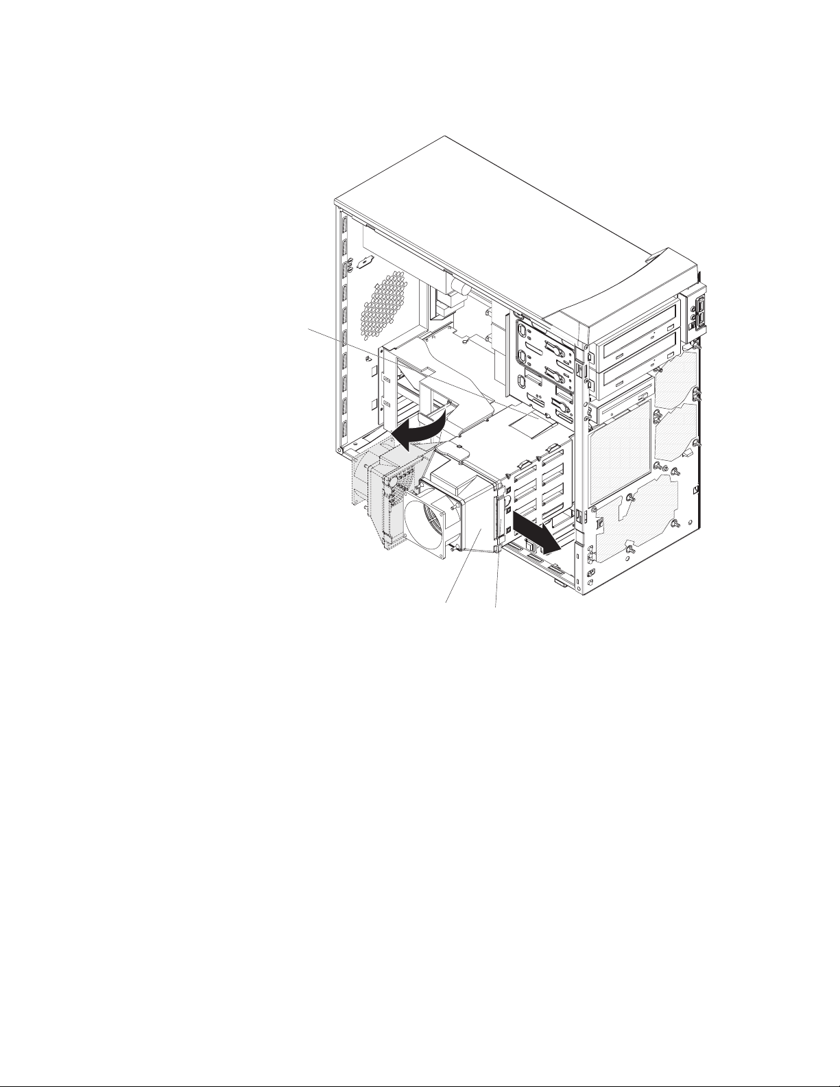
7. Grasp the fan latch on the fan assembly that is over the drive cage and pull it
outward to disengage it from the drive cage and rotate it to the side.
Drive-cage
retention tab
Fan assembly
Fan latch
8. If your computer has preinstalled hard disk drives in the drive cage, disconnect
the power and signal cables from the rear of the drives.
9. Remove the empty drive tray from the drive bay in which you want to install
the drive.
10. Touch the static-protective package containing the drive to any unpainted metal
surface on the computer; then, remove the drive from the package and place it
on a static-protective surface.
11. Set any jumpers or switches on the drive according to the documentation that
comes with the drive.
38 IntelliStation Z Pro Types 6223 and 6227: Hardware Maintenance Manual and Troubleshooting Guide
Page 49
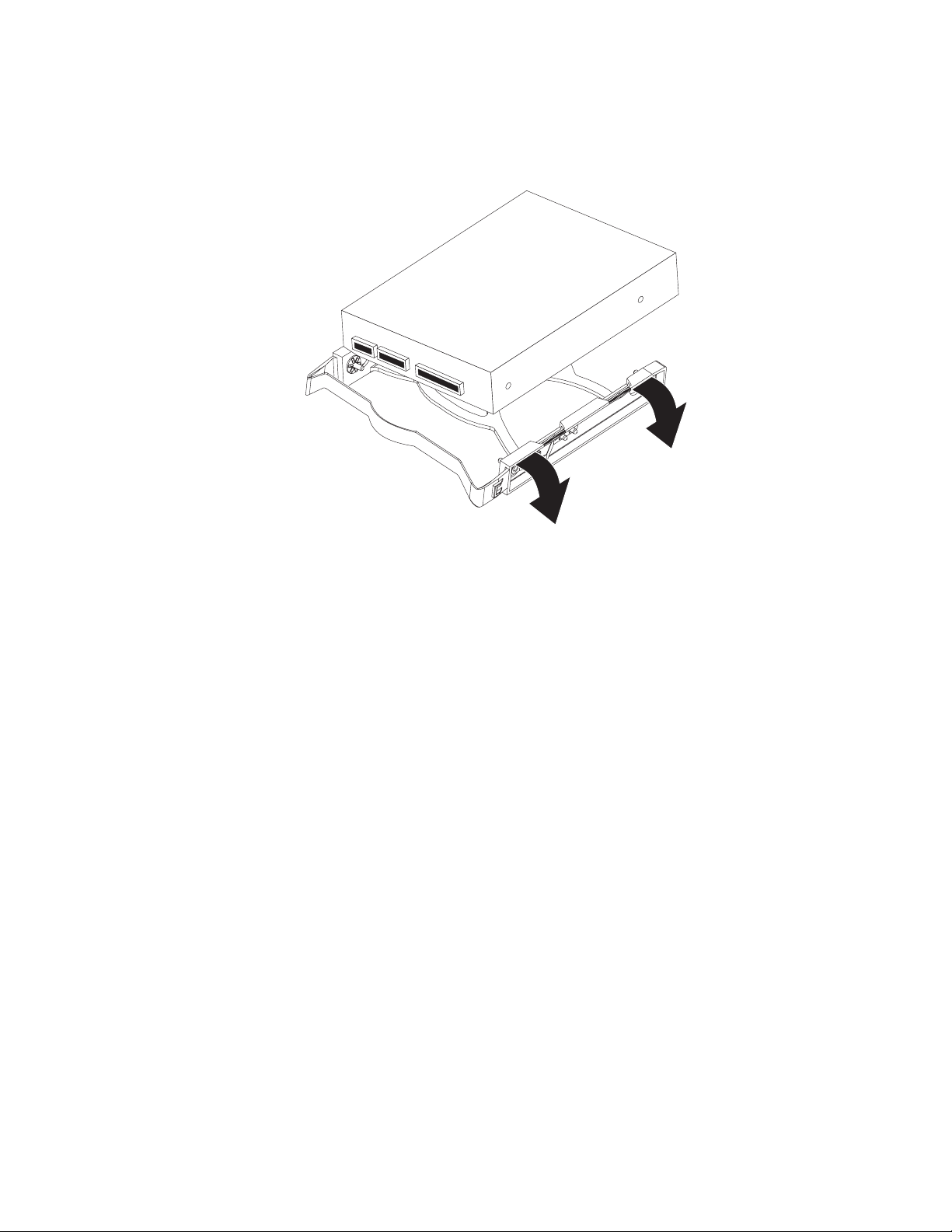
12. Attach the new drive to the drive tray. Place the drive on the drive tray and
align the holes on the drive with the mounting pins on the drive tray. Gently
pull both sides of the drive tray outward and insert the mounting pins into the
holes on the drive.
13. Align the drive assembly with the guide rails in the bay (make sure that the
connector end of the drive is facing you).
14. Gently slide the drive assembly into the drive bay until the drive snaps into
place.
15. Determine whether the new drive is a Serial ATA or SCSI device; then, connect
one end of the applicable signal cable into the back of the drive and the other
end of this cable into the applicable Serial ATA or SCSI connector on the
system board. See “Power and signal cables for internal drives” on page 40 for
additional information about cabling drives and “System board internal
connectors” on page 72 for the location of the Serial ATA and SCSI connectors
on the system board. If there are open connectors on the cables connecting
existing Serial ATA or SCSI drives, you can use these cables to connect the
new drive.
16. Route the signal cable so that it does not block the airflow to the rear of the
drives or over any microprocessor.
17. Connect the power cables to the back of the drives. The connectors are keyed
and can be inserted only one way.
18. Push the drive cage outward, and press in on the drive-cage release tab; then,
rotate the drive cage back into the computer.
19. Reconnect the connector for the fan that is attached to the back of the drive
cage to the system board.
20. If you have other options to install or remove, do so now. Otherwise, replace
the side cover (see “Replacing the side cover” on page 51.
21. Reconnect the external cables and power cords; then, turn on the attached
devices and the computer.
Chapter 4. Installing options 39
Page 50

Power and signal cables for internal drives
Your computer uses cables to connect IDE, Serial ATA, and SCSI devices to the
power supply and to the system board. (See “System board internal connectors” on
page 72 for the location of system-board connectors.) Review the following
information before connecting power and signal cables to internal drives:
v The drives that are preinstalled in your computer come with power and signal
cables attached. If you replace any drives, remember which cable is attached to
which drive, or label the cables.
v When you install a drive, make sure that one of the signal-cable connectors is
connected to the drive and that the connector at the other end of the signal cable
is connected to the system board.
v The computer has one IDE bus, which is primary.
v If you have only one IDE device on a cable, it must be set as a master device.
The following cables are provided:
v Power cables: Four-wire power cables connect the drives to the power supply.
At the end of these cables are plastic connectors that attach to different drives;
these connectors vary in size. With Serial ATA drives, you can use either a
four-wire power cable or a five-wire Serial ATA power cable, but do not use both
at the same time (use one or the other).
v Signal cables: Signal cables typically are flat cables, also called ribbon cables,
that connect IDE, Serial ATA, SCSI, and diskette drives to the system board. Two
or three types of signal cables come with your computer:
– IDE: The wider IDE signal cable has three connectors. One of these
connectors is attached to the drive, one is a spare, and the third is attached to
the primary or secondary IDE connector on the system board. The spare
connector can be used to connect additional IDE drives to your computer.
Note: The optical drive is attached to an ATA 100 signal cable. ATA 100
signal cables are color-coded. The blue connector is connected to the
system board. The black connector is connected to the master IDE
device. The gray middle connector is connected to the subordinate IDE
device.
– Serial ATA: The narrower, black signal cable has two connectors. One is
connected to the SATA drive, and the other is connected to the connector on
the system board. Each SATA drive comes with a cable. If you install an
additional SATA drive, you will need an additional cable.
– SCSI: The following cables can be used to attach SCSI devices to the
integrated SCSI controller on the system board:
- An Ultra320 twisted ribbon cable connects the internal Ultra320 SCSI hard
disk drive to the SCSI connector on the system board. This cable has four
additional connectors for attaching more internal SCSI devices.
- A round SCSI cable connects external SCSI devices to the integrated SCSI
controller on the system board. For more information about connecting
SCSI devices, see the SCSI documentation.
40 IntelliStation Z Pro Types 6223 and 6227: Hardware Maintenance Manual and Troubleshooting Guide
Page 51

Installing memory modules
The following notes describe the types of dual inline memory modules (DIMMs) that
the computer supports and other information that you must consider when installing
DIMMs:
v The computer comes with either two 256 MB or two 512 MB memory DIMMs
installed in DIMM 1 and DIMM 2 memory connectors. The second pair of DIMMs
must be installed in DIMM 3 and DIMM 4 memory connectors and the third pair
in DIMM 5 and DIMM 6 memory connectors.
v DIMMs must be installed in matched pairs. The DIMMs in each pair must be the
same size, speed, type, and technology as each other but do not have to match
the other pairs. You can mix compatible DIMMs from various manufacturers.
v Install only 1.8 V, 240-pin, double-data-rate 2 (DDR2), PC2-3200, registered,
synchronous dynamic random-access memory (SDRAM) with error correcting
code (ECC), dual inline memory modules (DIMMs). These DIMMs must be
compatible with the latest PC2-3200 SDRAM buffered DIMM specification. For a
list of supported options for your computer, go to http://www.ibm.com/pc/; then,
select your country and navigate to the list of options for your computer.
v The DIMM-installation sequence is based on single-rank, double-rank, and mixing
single-rank and double-rank memory DIMMs. Single-rank DIMMs are 256 MB,
512 MB, and 1 GB memory modules. Double-rank DIMMs are 2 GB memory
modules. The following table lists the DIMM-installation sequence for the
computer maximum memory capacity using mixed single-rank and double-rank
DIMMs.
Notes:
1. Do not install four, 2 GB double-rank DIMMs for the computer maximum
capacity (8 GB) configuration, the computer does not support it.
2. You can install pairs of 256 MB, 512 MB, 1 GB, and 2 GB DIMMs in the
computer, but for the computer maximum capacity, you must use the
DIMM-sequence in the table below.
3. You can install any combination of DIMM pairs in the computer, however, you
can install only two, 2 GB double-rank DIMMs in the computer and they must
go in DIMM connectors 1 and 2. Do not install 2 GB double-rank DIMMs in
any connectors other than DIMM connectors 1 and 2.
4. If you order memory DIMMs from IBM, the variable 2R in the description
indicates that the DIMM is a double-rank 2 GB DIMM.
Table 2. Maximum memory capacity (8 GB) and installation sequence mixing single-rank
and double-rank DIMMs
DIMM pair DIMM connectors DIMM size Rank
First pair 1, 2 2 GB Double-rank
Second pair 3, 4 1 GB Single-rank
Third pair 5, 6 1 GB Single-rank
v The system board contains six DIMM connectors and supports two-way memory
interleaving when the DIMMs are installed in pairs and functioning properly. If
one DIMM in the pair fails, the computer runs in single-channel mode
(non-interleaving). A failed DIMM must be replaced as soon as possible;
otherwise, the computer will not start (boot).
v The DIMM options that are available for the computer are 256 MB, 512 MB, 1
GB, and 2 GB memory modules. The computer supports a minimum of 512 MB
and a maximum of 8 MB (when using 2 GB double-rank DIMMs) of system
memory.
Chapter 4. Installing options 41
Page 52

Important: Although the computer supports a maximum of 8 GB of system
memory, the Microsoft Windows operating systems recognize and
support a maximum of 4 GB of system memory.
v The memory controller in the computer provides Chipkill memory protection if the
DIMMs are 1 GB or larger, or if the computer is populated with 512 MB x4
DIMMs. Chipkill memory protection is a technology that protects the computer
from a single chip failure on a DIMM.
v The amount of usable memory is reduced depending on the system
configuration. A certain amount of memory must be reserved for system
resources. The BIOS displays the total amount of installed memory and the
amount of configured memory.
Complete the following steps to install DIMMs:
1. Read the safety information beginning on page 127 and “Handling
static-sensitive devices” on page 23
2. Turn off the computer and all attached devices (see “Turning off the computer”
on page 9); then, disconnect all power cords and external cables.
3. Remove the side cover (see “Removing the side cover” on page 25).
4. Locate the DIMM connectors on the system board. Determine the connectors
into which you will install the DIMMs. See Table 2 on page 41 for additional
information on DIMM-installation sequences.
Table 3. DIMM installation sequence
DIMM pair DIMM connectors
First pair 1, 2
Second pair 3, 4
Third pair 5, 6
5. Gently open the retaining clip, if necessary, remove any existing DIMM.
6. Touch the static-protective package containing the DIMM to any unpainted
metal surface on the computer. Then, remove the new DIMM from the
package.
7. Gently open the retaining clip on each end of the DIMM slot. Turn the DIMM
so that the pins align correctly with the connector.
42 IntelliStation Z Pro Types 6223 and 6227: Hardware Maintenance Manual and Troubleshooting Guide
Page 53
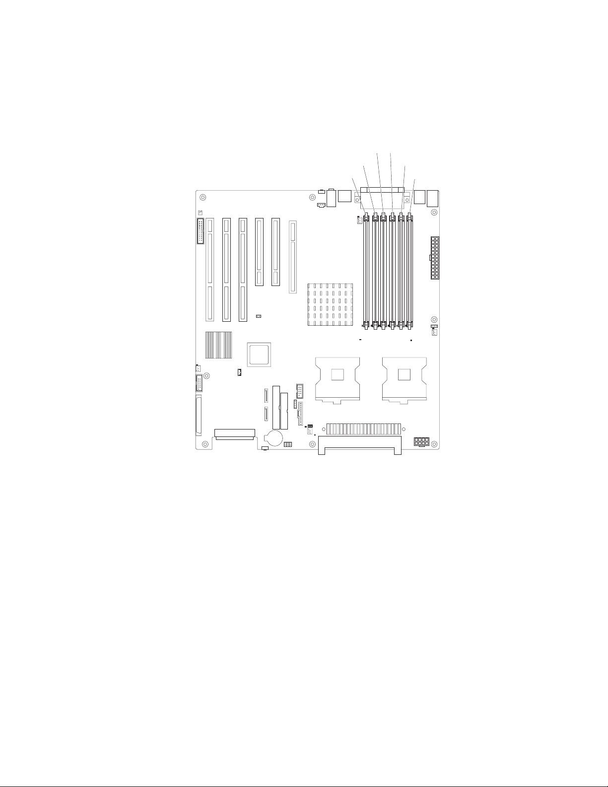
8. Insert the DIMM into the connector. Firmly press the DIMM straight down into
the connector by applying pressure on both ends of the DIMM simultaneously.
The retaining clips snap into the locked position when the DIMM is firmly
seated in the connector. If there is a gap between the DIMM and the retaining
clips, the DIMM has not been correctly installed. Open the retaining clips,
remove the DIMM, and then reinsert it.
DIMM 4 DIMM 3
DIMM 5
DIMM 2
DIMM 1DIMM 6
9. If you have other options to install or remove, do so now. Otherwise, replace
the side cover (see “Replacing the side cover” on page 51.
10. Reconnect the external cables and power cords. Turn on the attached devices,
and turn on the computer.
Chapter 4. Installing options 43
Page 54

Installing a second microprocessor
Your computer comes with one microprocessor installed on the system board. Your
computer supports up to two microprocessors. With two microprocessors, your
computer can operate as a symmetric multiprocessing (SMP) computer. With SMP,
certain operating systems and application programs can distribute the processing
load among the microprocessors.
Note: When installing microprocessor options, lay the computer on its side.
The following notes describe information that you must consider when installing an
additional microprocessor in your computer:
v Read the documentation that comes with the microprocessor to determine
whether you need to update the computer basic input/output system (BIOS)
code. The most current level of BIOS code for the computer is available from
http://www.ibm.com/support.
v (Optional) Obtain an SMP-capable operating system. For a list of supported
operating systems, go to http://www.ibm.com/pc/us/compat/.
v To ensure proper computer operation, use microprocessors that have the same
cache size and type, and the same clock speed. Microprocessor internal and
external clock frequencies must be identical. You can use the
Configuration/Setup Utility program in your computer to determine the specific
type of microprocessor on your system board.
Important: The first microprocessor must always be installed in the
Microprocessor 1 socket.
v The microprocessor speeds are automatically set for this computer; therefore,
you do not need to set any microprocessor frequency-selection jumpers or
switches.
v Terminator cards are not required for empty microprocessor sockets. However,
for airflow, an empty microprocessor socket must contain a microprocessor
baffle.
v If you need to replace a microprocessor, see “Microprocessor and heat sink” on
page 60.
v For additional illustrations of the system-board components, see “System board
option connectors” on page 71.
v To order additional microprocessor options, contact your IBM marketing
representative or authorized reseller.
v For a list of supported microprocessor options for your computer, go to
http://www.ibm.com/pc/; then, select your country and navigate to the list of
options for your computer
The Microsoft Windows XP operating system that comes preinstalled on your
computer automatically configures itself when an additional microprocessor is
installed. Other operating systems might have to be manually configured to support
an additional microprocessor. See the User’s Guide on the IBM IntelliStation
Documentation CD for instructions.
Complete the following steps to install an additional microprocessor:
1. Read the safety information beginning on page 127 and the guidelines in
“Handling static-sensitive devices” on page 23.
2. Turn off the computer and all attached devices. (See “Turning off the
computer” on page 9.)
44 IntelliStation Z Pro Types 6223 and 6227: Hardware Maintenance Manual and Troubleshooting Guide
Page 55
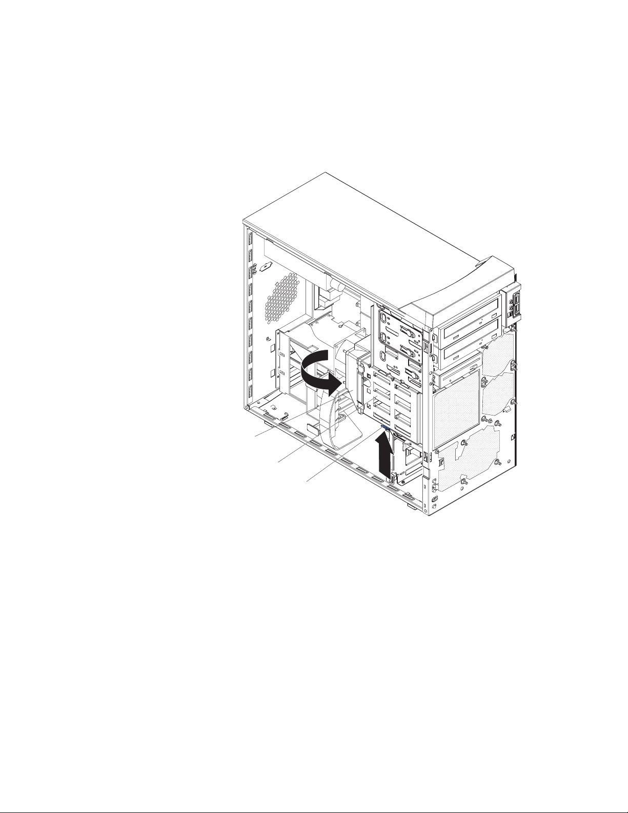
3. Disconnect all external cables and power cords.
4. Remove the side cover (see “Removing the side cover” on page 25).
5. Disconnect the fan connector for the fan that is attached to the back of the
drive cage from the system board.
6. Press in on the drive-cage release lever and rotate the drive cage all the way
out of the computer until it locks into place over the drive-cage retention tab.
The open ends of the drive slots and installed drives will face you.
Fan assembly
Drive-cage
Drive-cage
release lever
7. Move or disconnect any cables that might be in the way so you can remove
the microprocessors’ air baffle.
8. Remove the air baffle for the microprocessors by pulling it outward and lifting it
out of the computer.
Chapter 4. Installing options 45
Page 56
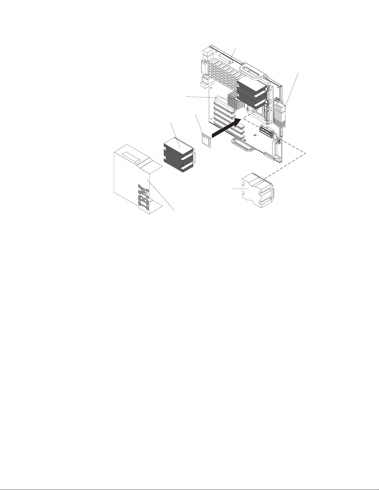
Heat sink
release lever
Microprocessor 2
Heat sink 2
DIMMs
VRM for second
microprocessor
Microprocessor
baffle assembly
Microprocessor
air baffle
9. Locate the second microprocessor socket (Microprocessor 2) on the system
board.
10. Remove the microprocessor baffle assembly from the second microprocessor
socket.
a. Press down on the blue touch point of the heat-sink release lever and
rotate the lever all the way out until it stops.
b. Grasp the front of the microprocessor baffle assembly and tilt it up while
pulling the rear flange out of the heat-sink retention module; then, lift it out
of the computer and store it in a safe place.
11. If the second microprocessor socket is covered with protective film or a label,
peel and remove the film or label.
12. Install the microprocessor:
a. Touch the static-protective package containing the new microprocessor to
any unpainted metal surface on the computer; then, remove the
microprocessor from the package.
b. Rotate the locking lever on the microprocessor socket from its closed and
locked position until it stops or clicks in the fully open position
(approximately 135°).
Attention: You must ensure that the locking lever on the microprocessor
socket is in the fully open position before you insert the microprocessor in
the socket. Failure to do so might result in permanent damage to the
microprocessor, microprocessor socket, and system board.
c. Position the microprocessor over the microprocessor socket. Align the
triangle on the corner of the microprocessor with the triangle on the corner
of the socket and carefully press the microprocessor into the socket.
46 IntelliStation Z Pro Types 6223 and 6227: Hardware Maintenance Manual and Troubleshooting Guide
Page 57
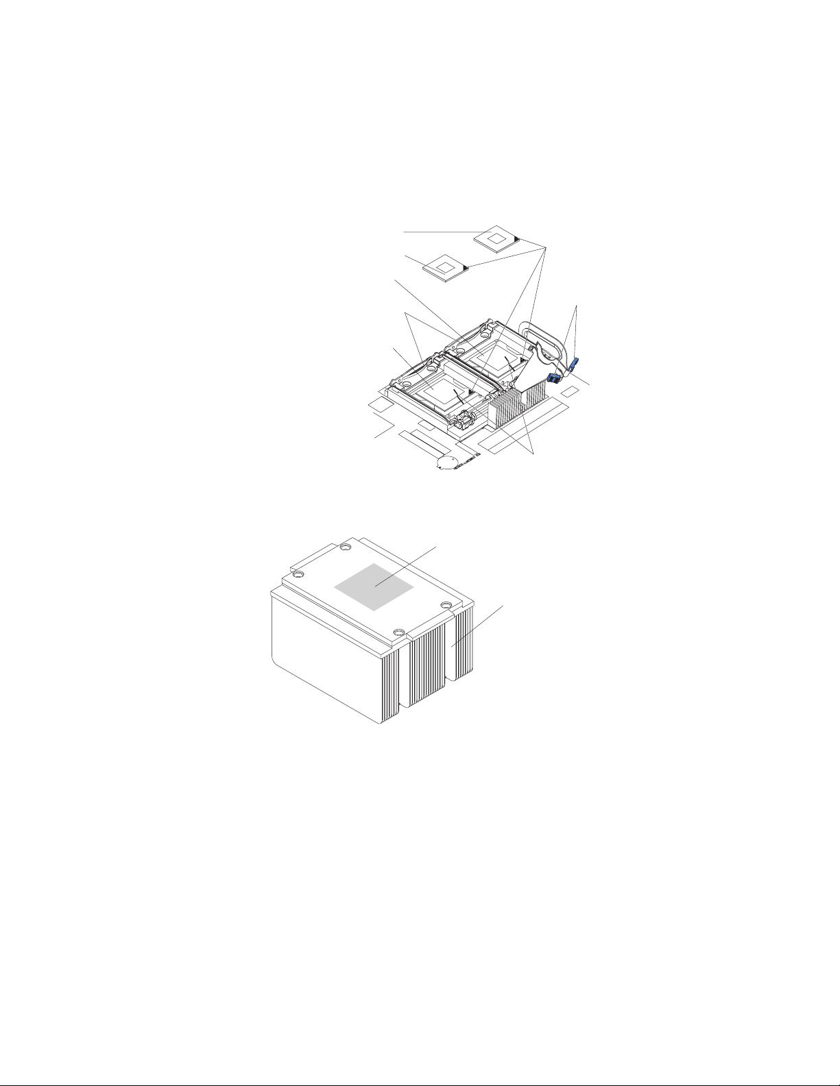
Attention:
1) Do not use excessive force when pressing the microprocessor into the
socket.
2) Make sure that the microprocessor is oriented and aligned correctly
with pin number 1 in the socket before you try to close the lever. The
following illustration shows the alignment marks for both
microprocessors and sockets.
Microprocessor 1
Microprocessor 2
Microprocessor
socket 1
Retention bracket
springs
Microprocessor
socket 2
Alignment marks
Heat-sink
release levers
Microprocessorrelease levers
d. Carefully close the lever to secure the microprocessor in the socket.
13. Install the heat sink on the microprocessor.
Thermal grease
Heat sink
a. Remove the plastic cover from the bottom of the heat sink.
Attention: Do not set the heat sink down after you remove the plastic
cover and do not touch the thermal grease on the bottom of the heat sink.
Touching the thermal grease will contaminate it. If the thermal grease on
the heat sink becomes contaminated, replace the heat sink.
b. Align the heat sink (grease side down) over the microprocessor and
retention bracket.
c. Slide the rear flange of the heat sink rearward into the opening beneath the
retention-bracket spring.
d. Press down firmly on the front of the heat sink until it is seated correctly.
e. Secure the heat sink to the microprocessor by rotating the heat-sink
release lever to the closed position and hooking it underneath the tab on
the microprocessor socket.
f. Insert the voltage regulator module (VRM) into the VRM connector.
Chapter 4. Installing options 47
Page 58

14. Replace the air baffle for the microprocessors. Slant the front of the air baffle
for the microprocessors downward at an angle while moving it forward; then,
rotate the rear of the air baffle down until it snaps into place (it will become
stationary).
15. Rotate the drive cage back into the computer and reconnect the fan connector
on the fan assembly on the drive cage to the system board.
16. If you have other options to install or remove, do so now. Otherwise, replace
the side cover (see “Replacing the side cover” on page 51.
17. Reconnect the external cables and power cords. Turn on the attached devices,
and turn on the computer.
Installing an external SCSI cable
To install an external SCSI connector on the rear of the computer, install an external
SCSI interface option. For a list of supported external SCSI interface options for
your computer, go to http://www.ibm.com/pc/.
The external SCSI interface option contains a SCSI cable with a connector at one
end and on the other end another connector or an expansion-slot cover with an
embedded connector. Complete the following steps to install and route the SCSI
cable in the computer:
1. Turn off the computer and all peripheral devices. Disconnect all power cords;
then, disconnect all external signal cables from the computer.
2. Remove the side cover (see “Removing the side cover” on page 25).
3. Open the front adapter-retention bracket and remove the rear adapter-retention
bracket from the PCI-X slots (see “Installing an adapter” on page 26 for
instructions). You might also have to remove longer adapters for access to the
SCSI connectors on the system board.
4. Connect the SCSI signal cable to the connector for SCSI channel A on the
system board. See “System board internal connectors” on page 72 for the
location of the SCSI channel A connector.
5. Route the SCSI cable between the chassis and PCI-X slot 5 to the back of the
computer. Make sure that the cable does not block the flow of air to the
microprocessors or hard disk drives.
6. Attach the external connector to the rear of the computer.
v If the external end of the SCSI cable has a standard SCSI connector,
complete the following steps:
a. Remove the SCSI-connector knockout from the rear of the computer.
b. Insert the external SCSI connector on the SCSI cable into the knockout
opening and secure it with the attached screws.
v If the external end of the SCSI cable has an expansion-slot cover with an
embedded connector, complete the following steps:
a. Remove an expansion-slot cover from an available PCI-X slot.
b. Insert the expansion-slot cover with embedded connector into the slot
opening.
48 IntelliStation Z Pro Types 6223 and 6227: Hardware Maintenance Manual and Troubleshooting Guide
Page 59

7. Replace any adapters that you removed in step 3. Close the front
adapter-retention bracket and replace the rear adapter-retention bracket.
8. Replace the cover (see “Replacing the side cover” on page 51).
9. Reconnect the external cables and power cords. Turn on the attached devices,
and turn on the computer.
10. Use the SCSISelect program to configure SCSI channel A.
Installing a security rope clip
To help prevent hardware theft, you can add a security rope clip and cable to your
computer. After you add the security cable, make sure that it does not interfere with
other cables that are connected to the computer.
Before you begin, obtain the following items:
v A flat-blade screwdriver
v An adjustable wrench
v A 19-mm (0.75-in.) rope clip or wire rope (similar to National Manufacturing
number 3230, stock number 176-735)
v Threaded nuts that fit the rope clip
v A security cable
v A lock, such as a combination lock or padlock
Complete the following steps to install a rope clip:
1. Turn off the computer and all attached devices.
2. Disconnect all external cables and power cords; then, remove the side cover.
See “Removing the side cover” on page 25
3. Use a screwdriver to remove the two metal knockouts.
4. Insert the rope clip through the rear panel; then, attach and tighten the nuts.
Chapter 4. Installing options 49
Page 60

5. Thread the cable through the rope clip and around an object that is not part of
or permanently secured to the building structure or foundation and from which
the cable cannot be removed. Fasten the cable ends together with a lock. After
you add the security cable, make sure that it does not interfere with other
cables that are connected to the computer.
Rope clip
6. If you have other options to install or remove, do so now; otherwise, replace the
side cover (see “Replacing the side cover” on page 51).
7. Reconnect the external cables and power cords. Turn on the attached devices,
and turn on the computer.
Replacing the bezel
Complete the following steps to replace the bezel:
1. Insert the tabs on the side of the bezel into the matching holes on the computer
chassis.
2. Push the bezel toward the computer until the tabs and bezel clips snap into
place.
50 IntelliStation Z Pro Types 6223 and 6227: Hardware Maintenance Manual and Troubleshooting Guide
Page 61

Replacing the side cover
Complete the following steps to replace the side cover.
1. Before installing the cover, check that all cables, adapters, and other
components are installed and seated correctly and that you have cleared all
work tools from inside the computer.
2. Install the side cover by placing it into position on the computer. Make sure that
the lip on the bottom of the cover rests inside the ledge on the bottom of the
chassis before rotating the cover toward the computer. Press down and forward
on the cover until it locks.
3. Reconnect the external cables and power cords to the computer.
4. Turn on the attached devices; then, turn on the computer.
Chapter 4. Installing options 51
Page 62

Connecting external options
You can connect a number of optional external devices to the connectors on the
rear and front of the computer.
Complete the following steps to connect an external device:
1. Read the safety information beginning on page 127, the guidelines in “Handling
static-sensitive devices” on page 23, and the documentation that comes with
your options.
2. Turn off the computer and all attached devices (see “Turning off the computer”
on page 9).
3. Follow the instructions that come with the option to prepare it for installation and
to connect it to the computer.
If you are attaching a SCSI device, see “Ultra320 SCSI connector” on page 56 for
SCSI ID and cabling information.
52 IntelliStation Z Pro Types 6223 and 6227: Hardware Maintenance Manual and Troubleshooting Guide
Page 63

Input/output connectors
Connect optional external devices to the connectors on the front and rear of the
computer.
Your computer has the following input/output (I/O) connectors:
v One audio line in
v Two audio line out
v Two audio microphone
v One Ethernet
v Two IEEE 1394A (FireWire)
v One keyboard
v One mouse
v One parallel
v Two serial
v Six Universal Serial Bus (USB) 2.0
v One video
The following illustration shows the locations of the connectors on the rear of the
computer. See “Controls, LEDs, and connectors” on page 6 for the locations of the
connectors on the front of the computer.
IEEE 1394A
Mouse
Keyboard
USB
1 and 2
Serial 1
Parallel
Serial 2
USB
3 and 4
Line out
(green)
Line in
(blue)
Microphone
(pink)
Video
(FireWire)
Optional serial or video
port knockout
Ethernet link
status LED
Ethernet
Ethernet transmit/
receive activity LED
SCSI knockout
The following sections describe these connectors.
Chapter 4. Installing options 53
Page 64

Audio connectors
Use the audio connectors to connect external audio equipment to the computer.
The following illustration shows the audio connectors.
Line out
(green)
Line in
(blue)
Mic
(pink)
Line in
There is one line-in connector on the rear of the computer. The computer receives
audio signals through this connector from an external audio device.
Line out
There are two line-out connectors, one on the front and one on the rear of the
computer. The computer sends audio signals through this connector to powered
speakers with built-in amplifiers, headphones, a multimedia keyboard, or the audio
line-in connector on a stereo system. The internal speaker in the computer is
disabled when a device is attached to this connector.
Mic
There are two microphone connectors, one on the front and one on the rear of the
computer. Connect a microphone to this connector to record sounds onto the hard
disk or to use speech-recognition software.
Auxiliary-device (pointing-device) connector
There is one auxiliary-device connector on the rear of the computer. Use this
connector to connect a mouse or other pointing device. The following illustration
shows an auxiliary-device connector.
6
4
2
5
3
1
Ethernet (RJ-45) connector
There is one Ethernet connector on the rear of the computer. Use this connector to
connect the computer to a 10-Mbps, 100-Mbps, or 1000-Mbps network. The
following illustration shows an Ethernet connector.
Activity LED
(green)
8
Connect a Category 3, 4, or 5 unshielded twisted-pair (UTP) cable to this connector.
The 100BASE-TX and 1000BASE-T Fast Ethernet standards require Category 5 or
higher cabling.
Link LED
(green)
1
54 IntelliStation Z Pro Types 6223 and 6227: Hardware Maintenance Manual and Troubleshooting Guide
Page 65

The Ethernet connector has one LED that indicates Ethernet-link status. When this
LED is lit, it indicates that there is an active connection on the Ethernet port. Activity
between the computer and the network is indicated by the Ethernet transmit/receive
activity LEDs on the front and rear of the computer (see “Controls, LEDs, and
connectors” on page 6).
IEEE 1394A (FireWire) connector
There is one 4-pin IEEE 1394A (FireWire) connector on the front of the computer
and one 6-pin IEEE 1394A (FireWire) connector on the rear of the computer. Use
these connectors to connect IEEE 1394 (FireWire) devices. The following
illustrations show the IEEE 1394A (FireWire) connectors.
4-pin IEEE 1394A (FireWire) connector (front)
3
4
21
6-pin IEEE 1394A (FireWire) connector (rear)
4
2
6
1
Keyboard connector
There is one keyboard connector on the rear of the computer. Use this connector to
connect a PS/2 (non-USB) keyboard. The following illustration shows a keyboard
connector.
6
4
2
If you attach a keyboard to this connector, USB ports and devices are disabled
during the power-on self-test (POST).
Parallel connector
There is one parallel connector on the rear of the computer. Use this connector to
connect a parallel device. The following illustration shows a parallel connector.
13
25
The parallel connector supports three standard Institute of Electrical and Electronics
Engineers (IEEE) 1284 modes of operation: standard parallel port (SPP), enhanced
parallel port (EPP), and extended capability port (ECP). If you configure the parallel
port to operate in bidirectional mode, it supports the ECP and EPP modes. When
the parallel connector is configured as bidirectional, use an IEEE 1284-compliant
3
5
5
3
1
1
14
Chapter 4. Installing options 55
Page 66
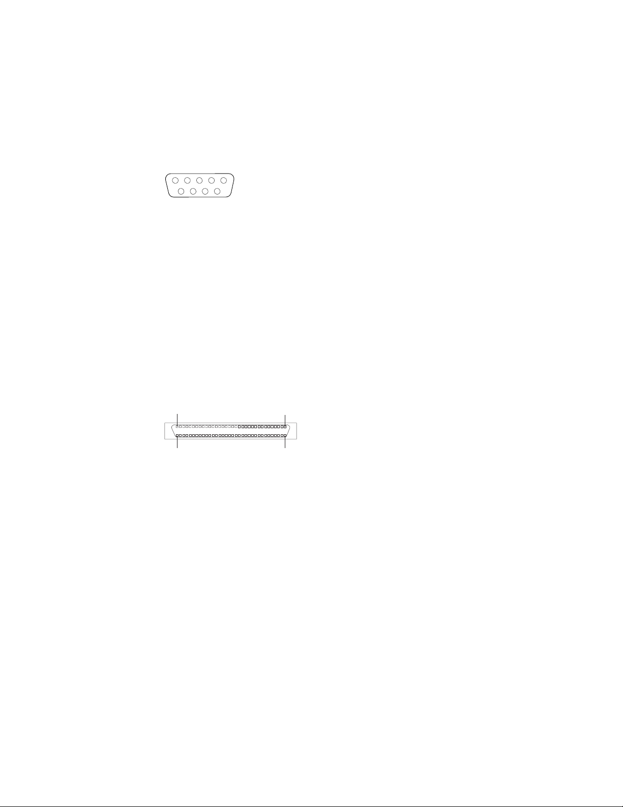
cable that does not exceed 3 meters (9.8 ft). Use the Devices and I/O Ports
options in the IBM Configuration/Setup Utility program to configure the parallel
connector as bidirectional.
Serial connectors
There are two serial connectors on the rear of the computer. Use these connectors
to connect serial devices. The following illustration shows a serial connector.
1
69
Ultra320 SCSI connector
Your computer has an integrated SCSI controller. This dual-channel controller
supports two independent, Ultra320 SCSI channels that support up to 15 SCSI
devices each. The SCSI connectors for the channels are on the system board. The
controller has the following features:
v Double-transition clocking to achieve up to 320 MBps (megabytes per second)
data-transfer rates
v Domain name validation to negotiate compatible data-transfer speeds with each
device
v Cyclic-redundancy checking (CRC) to improve data reliability
v An active terminator for SCSI bus termination
The following illustration shows a SCSI connector.
34
68
5
1
35
SCSI cabling requirements
You can install four internal SCSI devices using the SCSI signal cable that comes
with some computer models. If you plan to attach external SCSI devices, you can
order an additional SCSI cable, remove the SCSI knockout from the rear of the
computer, and connect the new cable from the SCSI channel A connector on the
system board to this opening. To select and order the correct cables for use with
external devices, contact your IBM marketing representative or authorized reseller.
See “System board internal connectors” on page 72 for the locations of the SCSI
connectors.
If you want to attach external SCSI devices to the computer without using the
internal SCSI channel B, you must install an optional SCSI adapter.
Setting SCSI IDs
Each SCSI device that is connected to a SCSI controller must have a unique SCSI
ID. This ID enables the SCSI controller to identify the device and ensure that
different devices on the same SCSI channel do not attempt to transfer data
simultaneously. SCSI devices that are connected to different SCSI channels can
have duplicate SCSI IDs. See the information that comes with the device for
instructions for setting its SCSI ID.
56 IntelliStation Z Pro Types 6223 and 6227: Hardware Maintenance Manual and Troubleshooting Guide
Page 67
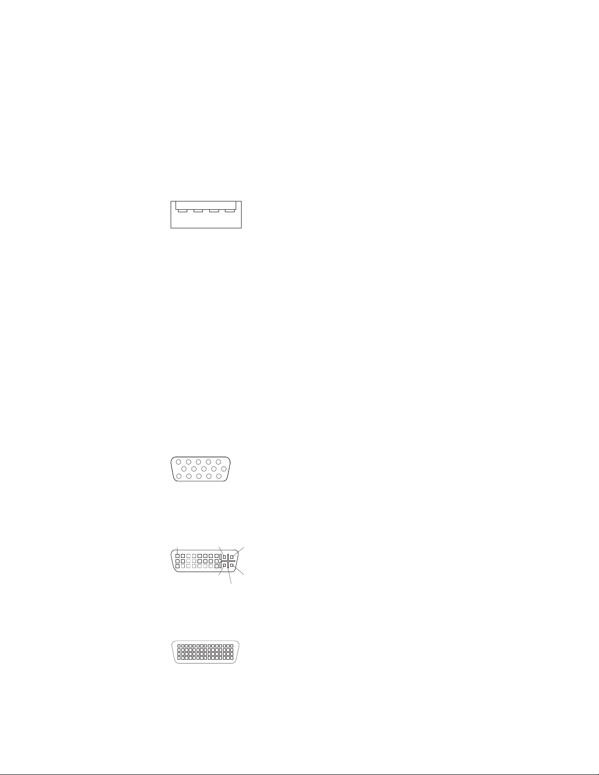
Universal Serial Bus connectors
There are six Universal Serial Bus (USB) 2.0 connectors, two on the front and four
on the rear of the computer. Use the USB connectors to connect optional telephony
and multimedia devices. USB 2.0 technology transfers data at up to 480 Mbps (Mb
per second) with a maximum of 127 external devices and a maximum signal
distance of 5 meters (16 ft) per segment (if the device that is attached to the
computer is a USB 2.0 device). If multiple USB devices are attached to the
computer, the USB hub must be USB 2.0; otherwise, all USB 2.0 devices will
transfer data at 12 Mbps. Using Plug and Play technology, USB devices are
configured automatically. The following illustration shows a USB connector.
14
Use a 4-pin USB cable to connect an external devices to a USB connector.
If you connect a PS/2 (non-USB) keyboard to the keyboard connector, USB ports
and devices are disabled during power-on self-test (POST).
If you connect a USB keyboard that has a mouse port, the keyboard emulates a
mouse, and you cannot disable the mouse settings in the Configuration/Setup Utility
program.
Video connector
The PCI Express x16 adapter, which is in PCI slot 1 on the system board, provides
the video connector. This connector is on the rear of the computer. Use the video
connector to connect a monitor or other display device. The following illustrations
show examples of different video connectors.
Analog video connector
5
1
1115
Digital (DVI-I) video connector
1
C1 C2
C3C5C4
Dual monitor system-59 (DMS-59) video connector
Some models come with a digital video interface (DVI) connector for connecting a
digital monitor. If you have problems viewing information with a second monitor,
refer to the User’s Guide.
Chapter 4. Installing options 57
Page 68
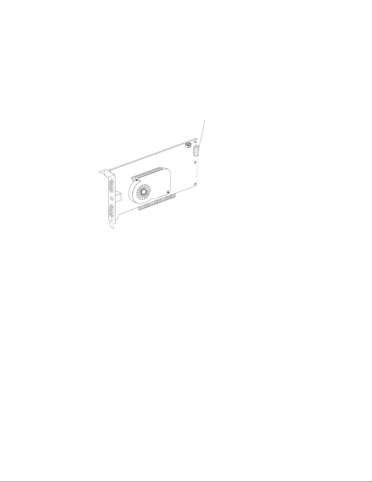
Models with the NVIDIA Quadro FX 1300 or NVIDIA Quadro FX 3400 video adapter
come with a DVI-I to VGA style analog converter for each DVI-I connector.
Attention: To get the best performance from the NVIDIA Quadro FX 3400 video
adapter, you must connect the video adapter to the computer power supply.
Otherwise, the video adapter will be operating with very limited power, resulting in a
decrease in performance for some applications. Use the PCI Express x16 external
power drop to connect the video adapter to the computer power supply. The
following illustration shows the location of the video adapter power connector.
Video adapter
power connector
Models with the NVIDIA Quadro NVS 280 video adapter come with a dual monitor
system-59 (DMS-59) to dual-analog monitor pigtail cable. If you want to set up two
digital monitors, you will have to purchase a separate dual-digital monitor cable.
58 IntelliStation Z Pro Types 6223 and 6227: Hardware Maintenance Manual and Troubleshooting Guide
Page 69

Chapter 5. Field replaceable units
Microprocessor and heat sink ...................60
CD-ROM drive .........................61
Non-hot swap power supply ....................62
Rear-adapter retention bracket ...................63
I/O card retainer ........................64
Front (microprocessor) fan ....................65
Hard drive fan .........................66
Power/LED switch assembly ....................68
Card/bracket assembly ......................69
Speaker ...........................70
System board .........................71
System board option connectors .................71
System board internal connectors .................72
System board external connectors .................73
System board error LEDs ....................74
System board jumpers and switches ................75
Removing the system board ...................76
Top/side cover .........................78
Bezel-release latch .......................79
Handle assembly ........................81
The following information describes procedures for removing and installing certain
components inside the system. Only a qualified service technician is authorized to
replace the components described in this section.
Important: The field replaceable unit (FRU) procedures are intended for trained
servicers who are familiar with IBM IntelliStation Z Pro products. See
the parts listing in “System replaceable units” on page 117 to determine
if the component being replaced is a customer replaceable unit (CRU)
or a FRU.
Note: Before servicing this system, read “Installation guidelines” on page 23 and
Appendix B, “Safety information,” on page 127.
© Copyright IBM Corp. 2004, 2009 59
Page 70
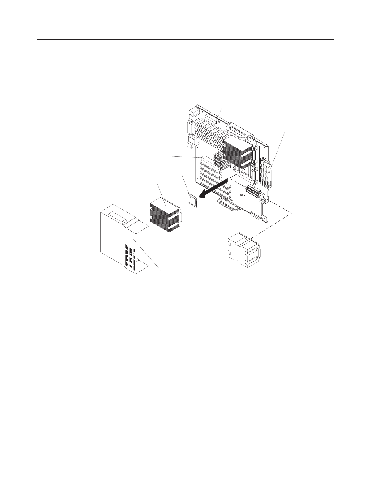
Microprocessor and heat sink
Before you begin:
v Read the “Installation guidelines” on page 23.
v Read Appendix B, “Safety information,” on page 127.
v Review the information in “System reliability considerations” on page 23.
To remove the microprocessor and heat sink, complete the following steps.
Heat sink
release lever
Microprocessor 2
Heat sink 2
DIMMs
VRM for second
microprocessor
Microprocessor
baffle assembly
Microprocessor
air baffle
1. Turn off the computer and remove external cables.
2. Remove the side cover (see “Removing the side cover” on page 25).
3. Disconnect any cables that impede access to the microprocessor.
4. Remove the heat sink from the microprocessor:
a. Press the microprocessor-baffle release lever down, move it toward the
other microprocessor, and lift it up to the open position.
b. Slide the heat-sink assembly toward the front of the computer and tip the
rear flange out of the heat-sink socket.
c. Lift the heat sink up and out of the computer.
Note: It might be necessary to gently twist the heat sink to loosen it from
the microprocessor.
Important: Be careful when handling the microprocessor and heat sink. If
the thermal grease between the microprocessor and heat sink
will be reused, do not contaminate it. If replacement thermal
grease is provided with the replacement part, be sure to remove
all traces of existing thermal grease from the remaining part
before applying the new thermal grease.
60 IntelliStation Z Pro Types 6223 and 6227: Hardware Maintenance Manual and Troubleshooting Guide
Page 71
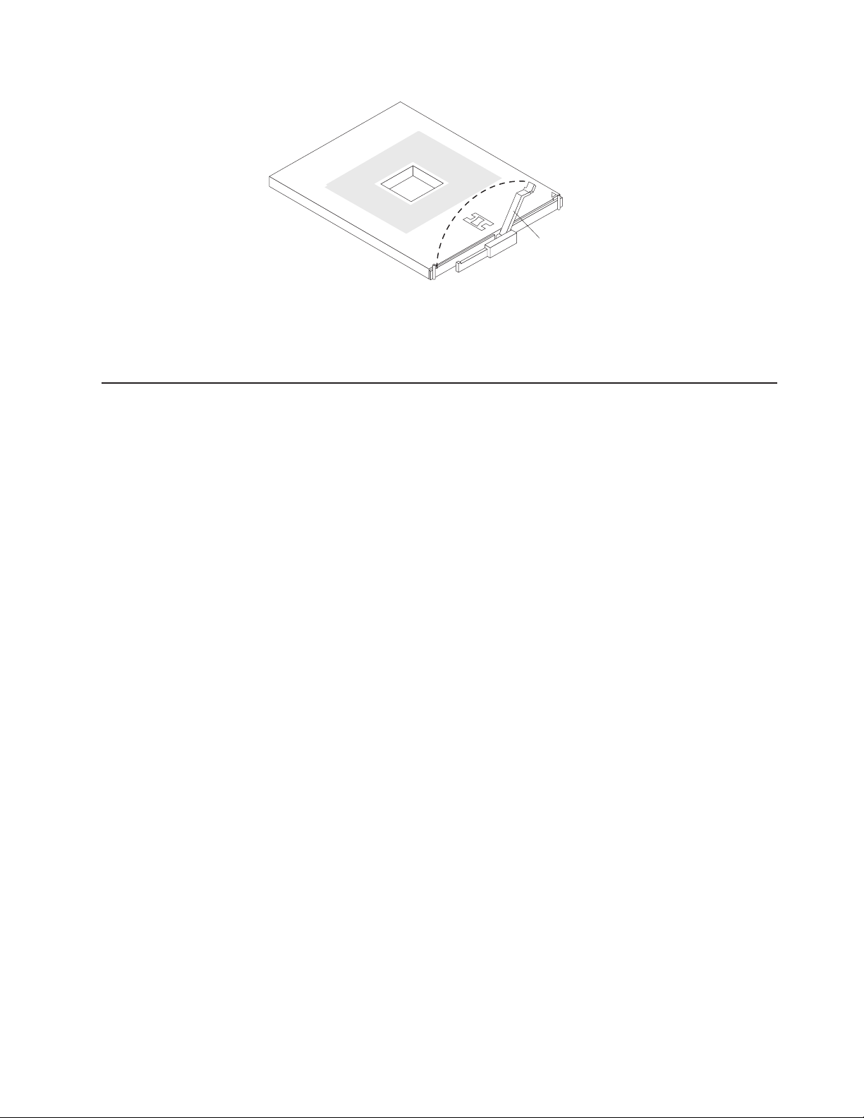
CD-ROM drive
Lever
fully
open
5. Rotate the microprocessor socket lever arm upward to its maximum vertical
position (135°), and lift the microprocessor up and out of the computer.
6. To install a microprocessor, see “Installing a second microprocessor” on page
44, beginning with step 8 on page 45.
Before you begin:
v Read Appendix B, “Safety information,” on page 127.
v Review the information in “System reliability considerations” on page 23.
To remove the CD-ROM drive, complete the following steps:
1. Turn off the computer, if it is on.
2. Disconnect the power cord from the power source and from the computer; then,
disconnect all external cables.
3. Remove the side cover (see “Removing the side cover” on page 25).
4. Remove the front bezel (see “Removing the bezel” on page 26).
5. Disconnect the CD-ROM drive connector and power cables from the rear of the
drive.
6. Press the touch point on the raised area of the drive cage for the CD-ROM
drive and gently slide the drive out of the front of the computer.
For instructions for replacing the CD-ROM drive, see “Installing a drive in bay 2 or
3” on page 32.
Chapter 5. Field replaceable units 61
Page 72
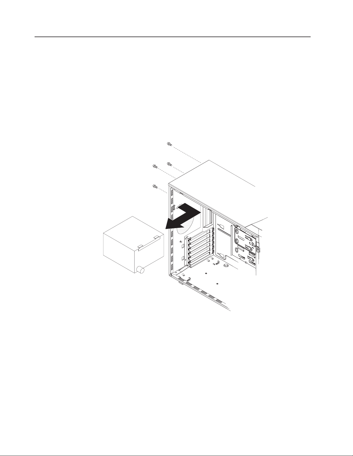
Non-hot swap power supply
Before you begin:
v Read Appendix B, “Safety information,” on page 127.
v Review the information in “System reliability considerations” on page 23.
To remove the non-hot-swap power supply, complete the following steps:
1. Turn off the computer, if it is on.
2. Disconnect the power cord from the power source and from the computer; then,
disconnect all external cables.
3. Remove the cover (see “Removing the side cover” on page 25).
4. Disconnect internal cables from the power supply to the system board and any
other components to which it is attached, making a note of where they connect.
5. Remove the screws from the rear of the computer.
6. Gently move the power supply away from the chassis and lift it out of the
computer.
To replace the non-hot-swap power supply, complete the following steps:
1. Align the tabs on the top of the power supply with the tab slots on the underside
of the top rear of the chassis, and slide the power supply toward the rear of the
chassis.
2. Secure the power supply to the rear of the chassis with the four screws.
3. Reconnect the power cables.
62 IntelliStation Z Pro Types 6223 and 6227: Hardware Maintenance Manual and Troubleshooting Guide
Page 73

Rear-adapter retention bracket
Before you begin:
v Read Appendix B, “Safety information,” on page 127.
v Review the information in “System reliability considerations” on page 23.
To remove the rear-adapter retainer, complete the following steps:
1. Turn off the computer, if it is on.
2. Disconnect the power cord from the power source and from the computer; then,
disconnect all external cables.
3. Remove the side cover (see “Removing the side cover” on page 25).
4. Remove all adapters (see “Installing an adapter” on page 26).
5. Grasp the rear adapter retainer, and gently slide the top and bottom tabs out of
the notches.
Rear adapter
retention bracket
To replace the rear adapter retainer, reverse the steps.
Chapter 5. Field replaceable units 63
Page 74

I/O card retainer
Before you begin:
v Read Appendix B, “Safety information,” on page 127.
v Review the information in “System reliability considerations” on page 23.
To remove the I/O card retainer, complete the following steps:
1. Turn off the computer, if it is on.
2. Disconnect the power cord from the power source and from the computer; then,
disconnect all external cables.
3. Remove the side cover (see “Removing the side cover” on page 25).
4. Remove all adapters (see “Installing an adapter” on page 26).
Release tab
Front view
Pivot
points
Rear view
5. Squeeze the two release tabs on the card retainer.
6. Pull out on the two pivot points of the retainer and remove it from the computer.
To replace the I/O card retainer, reverse the steps.
64 IntelliStation Z Pro Types 6223 and 6227: Hardware Maintenance Manual and Troubleshooting Guide
Page 75

Front (microprocessor) fan
Before you begin:
v Read Appendix B, “Safety information,” on page 127.
v Review the information in “System reliability considerations” on page 23.
To remove a front fan, complete the following steps:
1. Turn off the computer, if it is on.
2. Disconnect the power cord from the power source and from the computer;
then, disconnect all external cables.
3. Remove the cover (see “Removing the side cover” on page 25).
4. Remove the front bezel (see “Removing the bezel” on page 26).
5. Pivot the drive cage out until it locks in position.
Fan baffle
Fan baffle
release tabs
Processor fans
6. Squeeze the fan baffle release tabs so that they release from the notches in
the chassis.
Note: It might be easier to perform this procedure if you remove adapters and
remove the front I/O card retainer.
7. From inside the computer, grasp the fan baffle, slide it out, and remove it from
the computer.
8. Note where the fan cable connects to the system board, and disconnect the
cable from the system board.
Note: See the system service label or “System board internal connectors” on
page 72 for system board connector locations.
9. Use side cutters to cut the four rubber extensions that secure the fan to the
chassis.
10. Remove the fan from the computer, making sure that no rubber extensions are
left loose in the computer.
Chapter 5. Field replaceable units 65
Page 76

Hard drive fan
To install the new front fan assembly, complete the following steps:
1. Place the fan in position against the chassis.
2. Guide the rubber extensions through the apertures.
3. Use needle-nosed pliers to pull the extensions through the apertures.
4. Connect the fan cable.
5. Slide the fan baffle into place and guide the tabs into the slots in the chassis
until they lock in place.
6. If you removed the adapters and front I/O card retainer, replace the retainer and
then the adapters.
7. Press the touch point on the side of the drive cage and lower it back into place
in the computer.
8. Replace the bezel.
9. Replace the side cover.
Before you begin:
v Read Appendix B, “Safety information,” on page 127.
v Review the information in “System reliability considerations” on page 23.
To remove a rear fan, complete the following steps:
1. Turn off the computer, if it is on.
2. Disconnect the power cord from the power source and from the computer; then,
disconnect all external cables.
3. Remove the side cover (see “Removing the side cover” on page 25).
4. Rotate the drive cage up until it locks in position.
5. Note where the fan cable connects to the system board, and disconnect the
cable from the system board.
Note: See the system service label or “System board internal connectors” on
page 72 for system board connector locations.
66 IntelliStation Z Pro Types 6223 and 6227: Hardware Maintenance Manual and Troubleshooting Guide
Page 77

Fan
Fan latch
Fan assembly
6. On the side of the drive cage facing the front of the computer, grasp the fan
latch and pull it away from the drive cage, rotating it up.
7. Grasp the duct at the pivot points and pull them outward until they detach from
the drive cage.
8. Set the assembly on a level work surface with the fan facing up.
9. Use side cutters to sever the four rubber extensions securing the fan to the duct
and remove the fan.
To install the new rear fan assembly, reverse the previous steps, guiding the rubber
extensions through the apertures and using needle-nosed pliers to pull them
through.
Chapter 5. Field replaceable units 67
Page 78

Power/LED switch assembly
Before you begin:
v Read the “Installation guidelines” on page 23.
v Read Appendix B, “Safety information,” on page 127.
v Review the information in “System reliability considerations” on page 23.
To remove the power/LED switch assembly, complete the following steps:
1. Turn off the computer, if it is on.
2. Disconnect the power cord from the power source and from the computer; then,
disconnect all external cables.
3. Remove the side cover (see “Removing the side cover” on page 25).
4. Remove the front bezel (see “Removing the bezel” on page 26).
5. Note where the power-switch and LED panel cable connects to the system
board; then, carefully disconnect the cable from the system board.
Note: See the system service label or “System board internal connectors” on
page 72 for system board connector locations.
Release tab
6. From inside the computer, press the release tab.
7. Pull the assembly toward the rear of the computer and remove it.
To replace the power/LED switch assembly, reverse the previous steps, making
sure that the assembly clicks into place in the chassis.
68 IntelliStation Z Pro Types 6223 and 6227: Hardware Maintenance Manual and Troubleshooting Guide
Page 79

Card/bracket assembly
Note:
v Read “Installation guidelines” on page 23.
v Read the safety notices at Appendix B, “Safety information,” on page 127.
v Read “Handling static-sensitive devices” on page 23.
Complete the following steps to remove the card/bracket connector assembly:
1. Turn off the computer and attached devices.
2. Disconnect the power cord from the power source and from the computer; then,
disconnect all external cables.
3. Remove the side cover (see “Removing the side cover” on page 25.
4. Remove the front bezel (see “Removing the bezel” on page 26).
5. Press the latch on the top of the assembly; this side of the assembly will detach
from the chassis.
6. Remove the tab on the bottom part of the assembly from the slot in the chassis.
7. Pull the assembly out slightly and detach the two cables from the back of the
assembly.
To install the card/bracket connector assembly, reverse the previous steps, placing
the bottom tab into the slot in the chassis and then pressing the top of the
assembly into place.
Chapter 5. Field replaceable units 69
Page 80
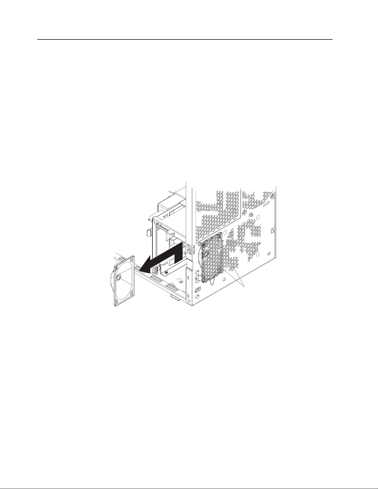
Speaker
Note:
v Read “Installation guidelines” on page 23.
v Read the safety notices at Appendix B, “Safety information,” on page 127.
v Read “Handling static-sensitive devices” on page 23.
Complete the following steps to remove the speaker:
1. Turn off the computer and attached devices.
2. Disconnect the power cord from the power source and from the computer; then,
disconnect all external cables.
3. Remove the side cover (see “Removing the side cover” on page 25.
4. Note where the speaker cable connects to the system board; then, carefully
disconnect the cable from the system board.
Note: See the system service label or “System board internal connectors” on
page 72 for system board connector locations.
Speaker retainer
tabs
5. Press the speaker retainer tabs to detach them from the chassis.
6. Grasp the speaker and slide it up to clear the notches, and remove it.
To install the speaker, reverse the previous steps.
70 IntelliStation Z Pro Types 6223 and 6227: Hardware Maintenance Manual and Troubleshooting Guide
Page 81
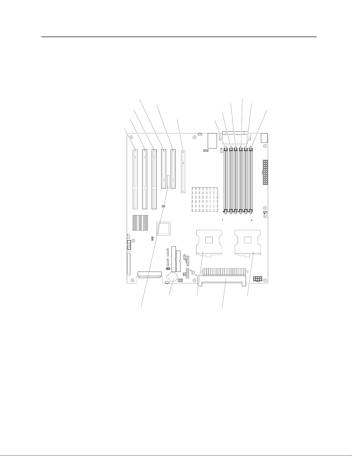
System board
This section contains service information for the system board.
System board option connectors
The following illustration shows the system board connectors for user-installable
options.
Slot 4 PCI-X
Slot 5 PCI-X
Slot 6 PCI-X
Slot 3 PCI
Slot 2 PCI
Slot 1 PCI
Express x 16
DIMM 5
DIMM 6
DIMM 4
DIMM 3
DIMM 2
DIMM 1
Battery
Remote Supervisor
Adapter II
Microprocessor 2
Microprocessor 2 VRM
Microprocessor 1
Chapter 5. Field replaceable units 71
Page 82
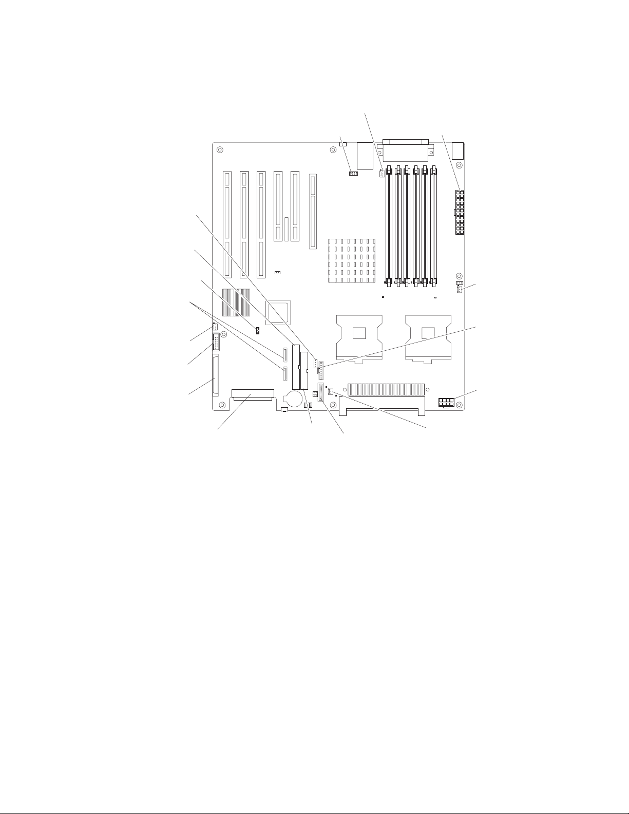
System board internal connectors
The following illustration shows the internal connectors on the system board.
SCSI
activity
LEDs
Primary
IDE
Wake
on LAN
Serial
ATA
Fan 4
Front
USB
SCSI
channel A
JCOM1
(to serial
port 2)
Fan 1
Main
power
Fan 2
Front panel
switch/LEDs
Microprocessor
power
SCSI
channel B
Diskette
drive
SCSI
backplane
Fan 3
72 IntelliStation Z Pro Types 6223 and 6227: Hardware Maintenance Manual and Troubleshooting Guide
Page 83
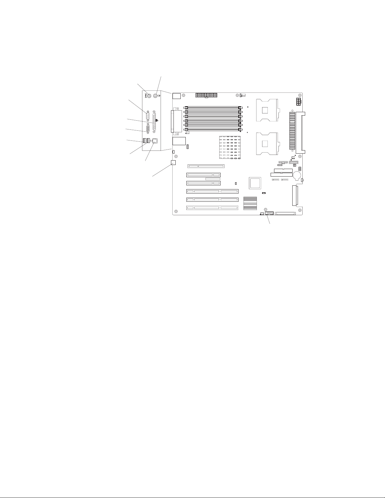
System board external connectors
The following illustration shows the external input/output port connectors on the
system board.
Mouse
Keyboard
Serial 1
Parallel
Video
USB 1
USB 2
Ethernet
Serial 2
2
1
Front USB
Chapter 5. Field replaceable units 73
Page 84
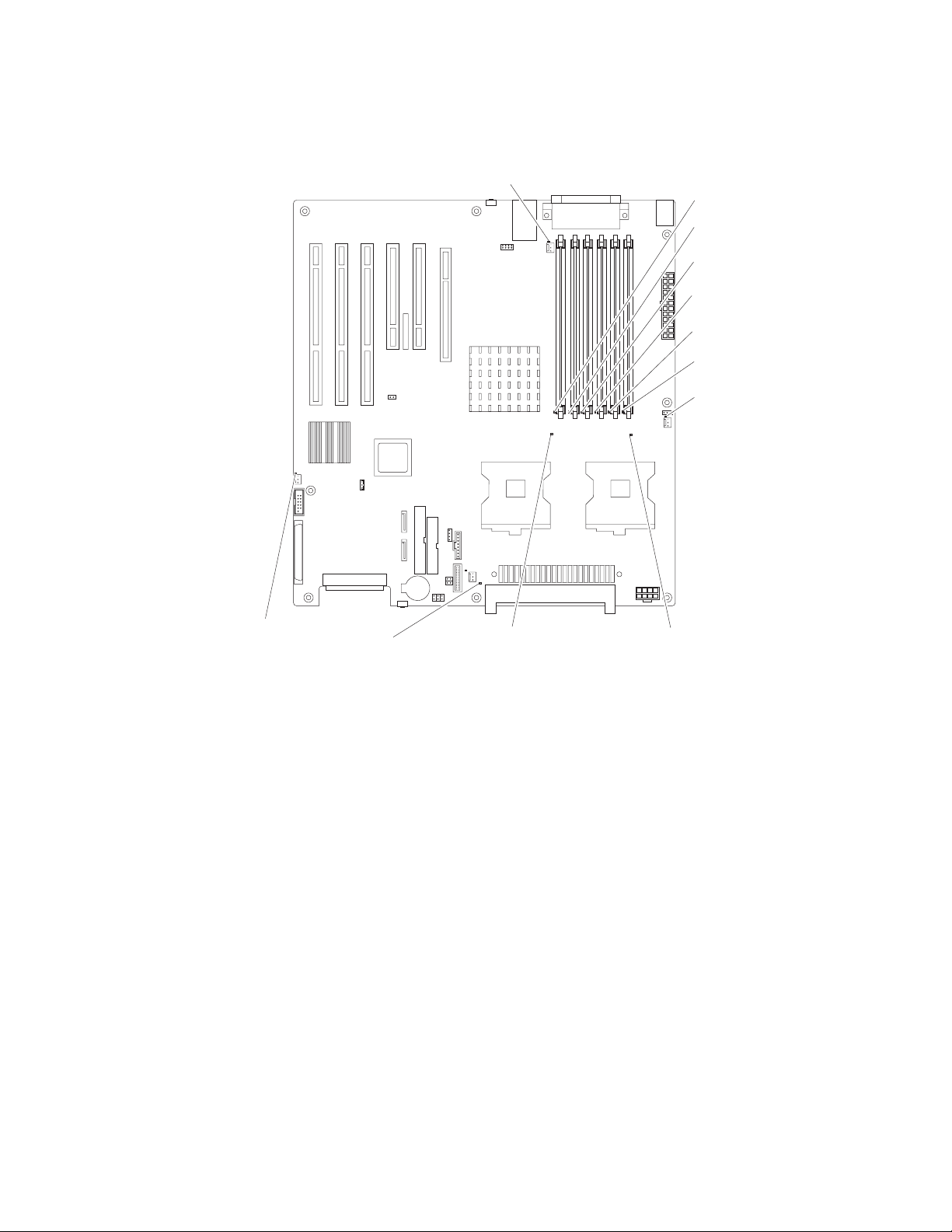
System board error LEDs
The following illustration shows the LEDs on the system board.
Fan 1
error LED (D26)
DIMM 6
error LED (D16)
DIMM 5
error LED (D17)
DIMM 4
error LED (D18)
DIMM 3
error LED (D19)
DIMM 2
error LED
DIMM 1
error LED (D21)
Fan 2
error LED (D27)
(D20)
Fan 4
error LED (D29)
Fan 3
error LED (D25)
(reserved)
Microprocessor 2
error LED (D22)
Microprocessor 1
error LED (D23)
74 IntelliStation Z Pro Types 6223 and 6227: Hardware Maintenance Manual and Troubleshooting Guide
Page 85
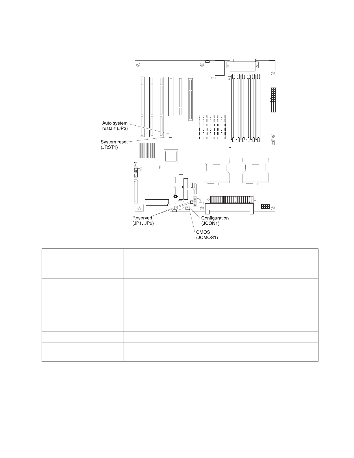
System board jumpers and switches
This section describes the jumpers and switches on the system board.
Jumper Settings
Auto system restart (JP3) (device
driver required for ASR
functionality)
Configuration (JCON1)
CMOS (JCMOS1)
Reserved (JP1, JP2)
System reset (JRST1)
v Auto restart enabled (default) (no jumper)
v Auto restart disabled (with jumper)
v Normal (default) (jumper on pins 1 and 2)
v Configuration (jumper on pins 2 and 3)
v BIOS crisis recovery (no jumper)
v Keep CMOS data (default) (jumper on pins 1 and 2)
v Clear CMOS data (jumper on pins 2 and 3 with power cords removed from
server)
v No jumper (default)
v Normal (default) (no jumper)
v Force system reset (debug only) (with jumper)
Chapter 5. Field replaceable units 75
Page 86

Removing the system board
Before you begin:
v Read Appendix B, “Safety information,” on page 127.
v Review the information in “System reliability considerations” on page 23.
Notes:
1. When replacing the system board, you must either update the server with the
latest firmware or restore the pre-existing firmware that the customer provides
on a diskette or CD image.
2. Removing the system board will be easier if the server is turned on its side.
To remove the system board, complete the following steps:
1. Turn off the server, if it is on.
2. Disconnect the power cord from the power source and from the server; then,
disconnect all external cables.
3. Remove the side cover (see “Removing the side cover” on page 25).
4. Rotate the drive cage to its upright position.
5. Remove the microprocessor air baffle.
6. Remove the adapters (see “Installing an adapter” on page 26).
7. Remove the heat sinks (see “Microprocessor and heat sink” on page 60).
8. Disconnect the cables on the system board, noting their locations.
Note: See the system service label or “System board internal connectors” on
page 72 for system board connector locations.
76 IntelliStation Z Pro Types 6223 and 6227: Hardware Maintenance Manual and Troubleshooting Guide
Page 87

Heat sink retention
module
System board
I/O port standoff
screws (6 places)
Heat sink retention
module screws (8 places)
System board
retention latch
9. Remove the six I/O port standoff screws and set them in a safe place.
10. Remove the eight heat sink retention module screws and set them in a safe
place; then, remove the heat sink retention module.
11. Move the retention latch toward the rear of the computer.
12. Grasp the sides of the system board assembly and slide it toward the front of
the computer until it detaches from the chassis; then, lift it out.
To replace the system board, reverse the previous steps.
Chapter 5. Field replaceable units 77
Page 88
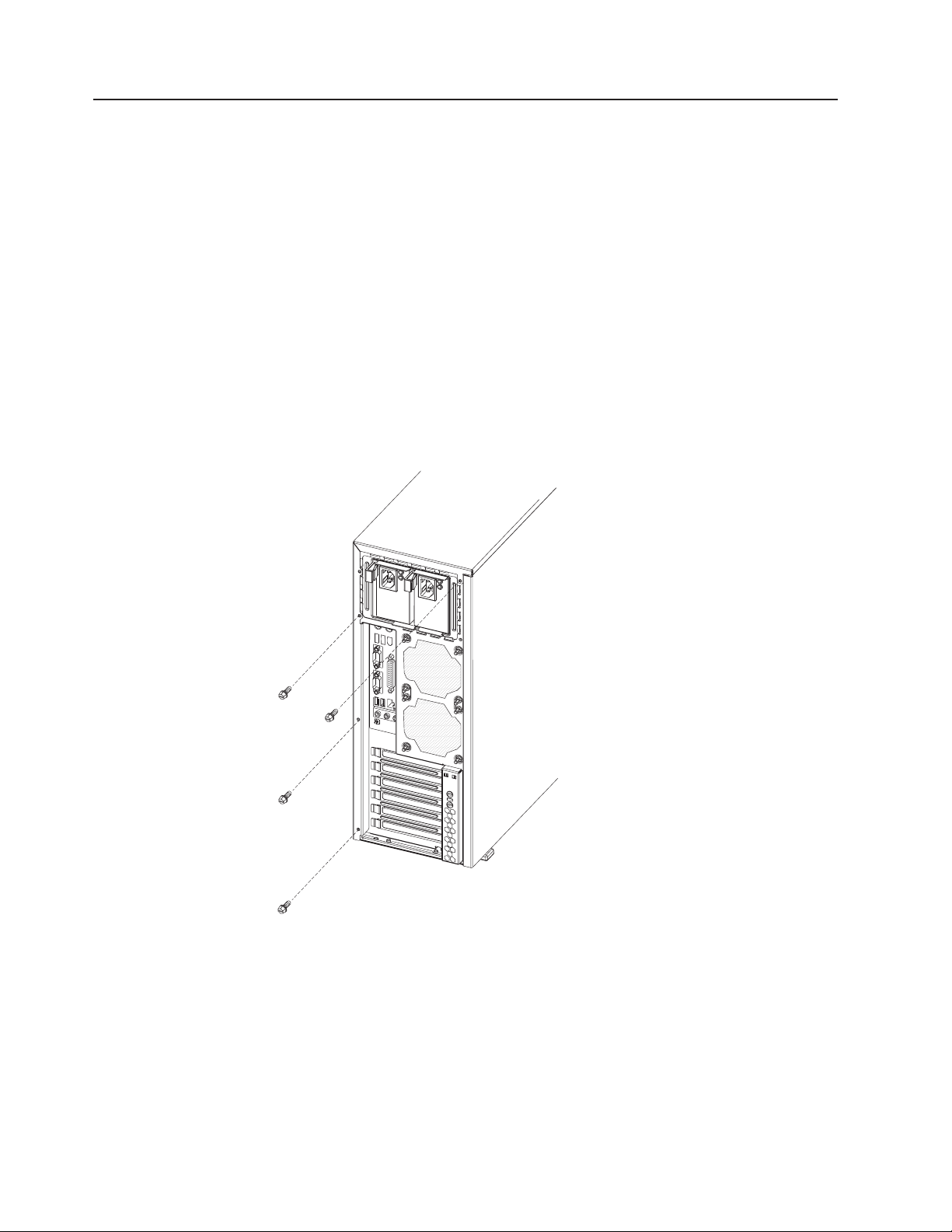
Top/side cover
Before you begin:
v Read Appendix B, “Safety information,” on page 127.
v Review the information in “System reliability considerations” on page 23.
To remove the top/side cover, complete the following steps:
1. Turn off the computer, if it is on.
2. Disconnect the power cord from the power source and from the computer; then,
disconnect all external cables.
3. Remove the side cover (see “Removing the side cover” on page 25).
4. Remove the front bezel (see “Removing the bezel” on page 26).
5. Remove the handle assembly (see “Handle assembly” on page 81).
6. Remove the four screws from the back of the computer and put them in a safe
place.
7. Using a screwdriver, gently pry the cover away from the computer in the rear
and slide the unit away from the computer.
To replace the top/side cover, reverse the steps.
78 IntelliStation Z Pro Types 6223 and 6227: Hardware Maintenance Manual and Troubleshooting Guide
Page 89
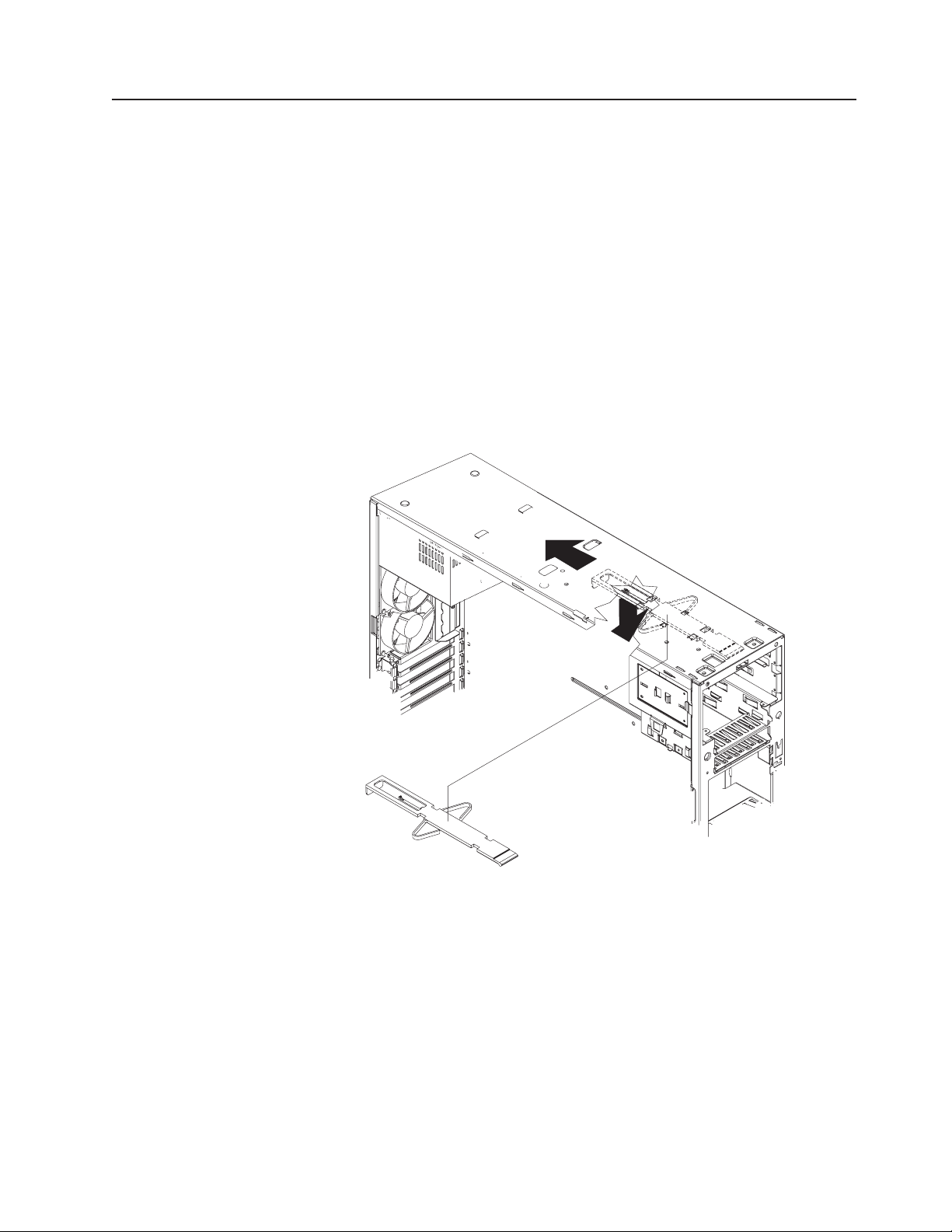
Bezel-release latch
Before you begin:
v Read Appendix B, “Safety information,” on page 127.
v Review the information in “System reliability considerations” on page 23.
To remove the bezel-release latch, complete the following steps:
1. Turn off the computer, if it is on.
2. Disconnect the power cord from the power source and from the computer; then,
disconnect all external cables.
3. Remove the side cover (see “Removing the side cover” on page 25).
4. Remove the front bezel (see “Removing the bezel” on page 26).
5. Remove the CD-ROM drive (see “CD-ROM drive” on page 61).
6. Pull down from inside the computer to release the latch tab.
7. From the underside, grasp the bezel-release latch in the center, and gently pull
it back and away from the computer.
Chapter 5. Field replaceable units 79
Page 90

To replace the bezel-release latch, complete the following steps:
1. Align the bezel-release latch with the slots on the underside of the top of the
chassis, and slide it into place.
2. Replace the CD-ROM drive (see “Installing a drive in bay 2 or 3” on page 32).
3. Replace the front bezel (see “Replacing the bezel” on page 50).
4. Replace the side cover (see “Replacing the side cover” on page 51).
5. Connect all external cables; then, connect the power cord, and reconnect the
computer to power.
6. Turn on the computer.
80 IntelliStation Z Pro Types 6223 and 6227: Hardware Maintenance Manual and Troubleshooting Guide
Page 91
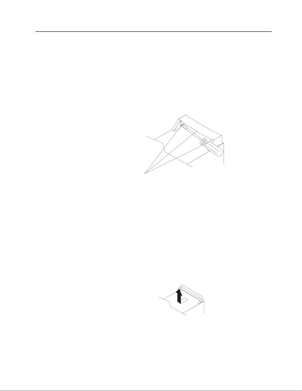
Handle assembly
Before you begin:
v Read Appendix B, “Safety information,” on page 127.
v Review the information in “System reliability considerations” on page 23.
To remove the handle cap, complete the following steps:
1. Turn off the computer, if it is on.
2. Disconnect the power cord from the power source and from the computer; then,
3. Use a flathead screwdriver to gently press in and down on the tabs on the
disconnect all external cables.
interior side wall of the handle.
Tab locations
4. Lift up on the handle cap to separate it from the handle support.
5. Turn the system back to the tower orientation; then, remove the top handle.
a. Carefully use a flat-blade screwdriver to push in the tabs inside the plastic
cover on the top of the system; then, remove the plastic cover. Store the
cover for possible future use.
b. Grasp the metal handle and slide it toward the rear of the computer to
remove it from the computer. Store the metal handle for possible future use.
To remove the handle support, complete the following steps:
1. Turn off the computer, if it is on.
2. Disconnect the power cord from the power source and from the computer; then,
disconnect all external cables.
3. Firmly grasp the handle support, and slide it away from the front bezel.
4. Lift up on the handle support to remove it from the slots in the top of the
chassis.
To install the handle assembly, reverse the steps.
Chapter 5. Field replaceable units 81
Page 92

82 IntelliStation Z Pro Types 6223 and 6227: Hardware Maintenance Manual and Troubleshooting Guide
Page 93

Chapter 6. Symptom-to-FRU index
This index supports IntelliStation Z Pro Types 6223 and 6227 computers.
Notes:
1. Check the configuration before you replace a CRU or FRU. Configuration
problems can cause false errors and symptoms.
2. For IBM devices that are not supported by this index, see the documentation for
that device.
3. Always start with “General checkout” on page 13.
The symptom-to-FRU index lists symptoms, errors, and the possible causes. The
most likely cause is listed first. Use this symptom-to-FRU index to help you decide
which FRUs to have available when servicing the computer.
The first column of the two-column tables in this index lists error codes or
messages, and the last column lists one or more suggested actions or FRUs to
replace. Take the action (or replace the FRU) that is suggested first in the list, and
then try the computer again to see whether the problem has been corrected.
Note: Try reseating a suspected component or reconnecting a cable before
replacing the component.
The POST BIOS code displays POST error codes and messages on the screen.
Beep symptoms
Beep symptoms are short tones or a series of short tones separated by pauses
(intervals without sound). See the examples in the following table.
Beeps Description
1-2-3 v One beep
v A pause (or break)
v Two beeps
v A pause (or break)
v Three beeps
4 Four continuous beeps
One beep after successfully completing POST indicates the computer is functioning
properly.
Note: See “System replaceable units” on page 117 to determine which components should be replaced by a field
service technician.
Beep/symptom FRU/action
1-1-2
(Microprocessor register test failed.)
1-1-3
(CMOS write/read test failed.)
1-1-4
(BIOS EEPROM checksum failed.)
v Microprocessor
1. Battery
2. System board
1. Recover BIOS
2. System board
© Copyright IBM Corp. 2004, 2009 83
Page 94

Note: See “System replaceable units” on page 117 to determine which components should be replaced by a field
service technician.
Beep/symptom FRU/action
1-2-1
(Programmable Interval Timer failed.)
1-2-2
(DMA page register test failed.)
1-2-3
(DMA page register write/read
failed.)
1-3-1
(First 64K RAM test failed.)
2-1-1
(Secondary DMA register failed.)
2-1-2
(Primary DMA register failed.)
2-1-3
(Primary interrupt mask register
failed.)
2-1-4
(Secondary interrupt mask register
failed)
2-2-2
(Keyboard controller failed.)
2-2-3
(CMOS power failure and checksum
check failed.)
2-4-1
(Video failed; system believed
operable.)
3-1-1
(Timer tick interrupt failed.)
3-1-2
(Interval timer channel 2 failed.)
3-1-3
(RAM test failed above address
OFFFFH.)
3-1-4
(Time-Of-Day clock failed.)
3-2-1
(Serial port failed.)
3-2-2
(Parallel port failed.)
3-2-3
(Math coprocessor test failed.)
v System board
v System board
v System board
1. DIMM
2. Memory adapter
v System board
v System board
v System board
v System board
1. Keyboard
2. System board
1. Battery
2. System board
v System board
v System board
v System board
1. DIMM
2. System board
1. Battery
2. System board
v System board
v System board
1. Optional microprocessor
2. Microprocessor
3. System board
84 IntelliStation Z Pro Types 6223 and 6227: Hardware Maintenance Manual and Troubleshooting Guide
Page 95

Note: See “System replaceable units” on page 117 to determine which components should be replaced by a field
service technician.
Beep/symptom FRU/action
3-2-4
(Failure comparing CMOS memory
size against actual.)
3-3-1
(Memory size mismatch occurred.)
3-3-2
(Critical SMBus error occurred, I2C
error)
1. DIMM
2. Battery
3. System board
1. DIMM
2. Battery
3. System board
1. Disconnect the computer power cord from outlet, wait 30 seconds,
and retry.
2. Microprocessor
3. DIMMs
4. SCSI backplane
5. SCSI power cable
6. System board
No-beep symptoms
Note: See “System replaceable units” on page 117 to determine which components should be replaced by a field
service technician.
No-beep symptom FRU/action
No beep occurs during POST.
No beep, no video, and the
system attention LED is off.
No beep, no video, and a
system board error LED is on.
BIST failed.
v System board
v System board
v See “System board error LEDs” on page 74.
v Microprocessor
POST error codes
In the following error codes, X can be any number or letter.
Note: See “System replaceable units” on page 117 to determine which components should be replaced by a field
service technician.
Error code/symptom FRU/action
062
(Three consecutive boot failures using the
default configuration.)
101, 102, 106
(Timer tick interrupt failure)
102
(Timer 2 test failure)
106
(Diskette controller error)
1. Run the Configuration/Setup Utility program.
2. Battery.
3. System board.
4. Microprocessor.
v System board
v System board
v System board
Chapter 6. Symptom-to-FRU index 85
Page 96

Note: See “System replaceable units” on page 117 to determine which components should be replaced by a field
service technician.
Error code/symptom FRU/action
129
(Internal cache (L1) error)
151
(Real time clock error)
161
(Real time clock battery error)
162
(Device configuration error)
Note: Be sure to load the default settings
and any additional desired settings; then,
save the configuration.
163
(Real-time clock error)
164
(Memory configuration changed.)
175
(EEPROM CRC #1 damaged.)
184
(Power-on password damaged)
185
(Drive startup sequence information
corrupted)
187
(VPD serial number not set.)
188
(EEPROM CRC #2 damaged.)
189
(An attempt made to enter the system with
invalid passwords)
196
(Microprocessor cache mismatch)
198
(Microprocessor speed mismatch)
199
(Microprocessors not in recommended
configurations)
201
(Memory test error.)
1. Optional microprocessor
2. Microprocessor
1. Battery
2. System board
1. Run the Configuration/Setup Utility program.
2. Battery.
3. System board.
1. Run the Configuration/Setup Utility program.
2. Battery.
3. Failing device.
4. System board.
1. Run the Configuration/Setup Utility program.
2. Battery.
3. System board.
1. Run the Configuration/Setup Utility program.
2. DIMM.
3. System board.
1. If Remote Supervisor Adapter II is installed, make sure that the
latest firmware is installed.
2. System board
1. Run the Configuration/Setup Utility program.
2. System board.
1. Run the Configuration/Setup Utility program.
2. System board.
1. Set serial number in the Configuration/Setup Utility program.
2. System board.
1. Run the Configuration/Setup Utility program.
2. System board.
1. Run the Configuration/Setup Utility program.
2. System board.
1. Make sure that microprocessors are of same type and speed.
2. Microprocessor.
1. Make sure that microprocessors are of same type and speed.
2. Microprocessor.
1. Make sure that microprocessors are of same type and speed.
2. Microprocessor.
1. DIMM
2. System board
86 IntelliStation Z Pro Types 6223 and 6227: Hardware Maintenance Manual and Troubleshooting Guide
Page 97

Note: See “System replaceable units” on page 117 to determine which components should be replaced by a field
service technician.
Error code/symptom FRU/action
229
(Internal cache (L2) error)
289
(DIMM disabled by the user or system.)
1. Microprocessor
2. Optional microprocessor
1. Run the Configuration/Setup Utility program.
2. DIMM.
3. System board.
301
(Keyboard or keyboard controller error)
303
(Keyboard controller error)
602
(Invalid diskette boot record)
1. Keyboard
2. System board
1. Replace the PS/2 keyboard with a USB keyboard.
2. System board.
1. Diskette
2. Diskette drive
3. Drive cable
4. System board
604
(Diskette drive error)
1. Run the Configuration/Setup Utility program and diagnostics.
2. Diskette drive.
3. Drive cable.
4. System board.
662
(Diskette drive configuration error)
1. Run the Configuration/Setup Utility program and diagnostics.
2. Diskette drive.
3. Drive cable.
4. System board.
962
(Parallel port configuration error)
1162
(Serial port configuration error)
11XX
(System board serial port 1 or 2 error)
1601
(BIOS code update needed)
1602
(Cable for optional Remote Supervisor
Adapter II not installed)
1762
(Hard drive configuration error, IDE only.)
1. Run the Configuration/Setup Utility program.
2. System board.
v System board
1. Run the Configuration/Setup Utility program.
2. System board.
1. Download and install latest level of BIOS code.
2. System board.
v Disconnect all computer and option power cords from computer,
wait 30 seconds, reconnect, and retry.
1. Hard disk drive.
2. Hard disk cables.
3. Run the Configuration/Setup Utility program.
4. System board.
178X
(Hard drive error, IDE only.)
1. Hard disk cables
2. Hard disk adapter
3. Hard disk drive
4. System board
Chapter 6. Symptom-to-FRU index 87
Page 98

Note: See “System replaceable units” on page 117 to determine which components should be replaced by a field
service technician.
Error code/symptom FRU/action
1800
(No more hardware interrupt available for
PCI adapter.)
1801
(No more ROM space available for PCI
adapter.)
1802
(Unavailable I/O address for PCI adapter)
1803
(Unavailable memory address for PCI
adapter)
1804
(Unavailable memory address for PCI
adapter)
1805
(PCI ROM error occurred)
1806
(PCI-to-PCI bridge error occurred)
1807
(xxxxyyyy PCI device unresponsive or
disabled by user, where xxxx=PCI vendor
ID and yyyy=PCI device ID)
1808
(Unsupported PCI device is installed)
1962
(Drive does not contain a valid boot
sector)
2400 (Video controller test failure)
1. Run the Configuration/Setup Utility program.
2. Remove adapter.
1. Run the Configuration/Setup Utility program.
2. Remove adapter.
3. Disable the adapter BIOS and run the Configuration/Setup Utility
program.
1. Start the Configuration/Setup Utility program and make sure that
I/O addresses for all adapters are set correctly.
2. Adapter.
3. System board.
1. Start the Configuration/Setup Utility program and make sure that
memory addresses for all other adapters are set correctly.
2. Adapter.
3. System board.
1. Remove an adapter to make memory address space available.
2. Disable adapter BIOS on adapter.
3. Adapter.
4. System board.
1. Remove all adapters and reinstall one at a time, restarting the
computer each time, until the failing adapter is determined;
then, replace that adapter.
2. System board.
1. Remove all adapters and reinstall one at a time, restarting the
computer each time, until the failing adapter is determined;
then, replace that adapter.
2. System board.
1. Run the Configuration/Setup Utility program and make sure the
device is enabled.
2. Adapter.
3. System board.
1. Remove all adapters and reinstall one at a time, restarting the
computer each time, until the failing adapter is determined;
then, replace that adapter.
2. System board.
1. Verify that a startable operating system is installed.
2. Run diagnostics.
3. Hard disk drive.
4. SCSI backplane.
5. Cable.
6. System board.
1. Video adapter (if installed)
2. System board.
88 IntelliStation Z Pro Types 6223 and 6227: Hardware Maintenance Manual and Troubleshooting Guide
Page 99

Note: See “System replaceable units” on page 117 to determine which components should be replaced by a field
service technician.
Error code/symptom FRU/action
2462
(Video configuration error)
5962
(IDE CD-ROM drive configuration error)
1. Video adapter (if installed)
2. System board.
1. Run the Configuration/Setup Utility program.
2. CD-ROM drive.
3. CD-ROM power cable.
4. IDE cable.
5. System board.
6. Battery.
8603
(Pointing-device error)
00012000
(Machine check architecture error.)
00019502
(Microprocessor 1 failed)
00019xxx (Microprocessor x not
functioning)
1. Pointing device
2. System board
1. Microprocessor
2. System board.
1. Microprocessor
2. System board
1. Verify microprocessor x is installed correctly.
2. Microprocessor x.
3. VRM, if installed.
4. System board.
00151200 (Unrecoverable error,
microprocessor x reported IERR)
1. Microprocessor x
2. VRM
3. System board
00180100
(No room for PCI option ROM)
1. Run the Configuration/Setup Utility program.
2. Failing adapter.
3. System board.
00180200
(No more I/O space available for PCI
adapter.)
1. Run the Configuration/Setup Utility program.
2. Adapter.
3. System board.
00180300
(No more memory above 1MB for PCI
adapter.)
1. Run the Configuration/Setup Utility program.
2. Adapter.
3. System board.
00180400
(No memory below 1 MB for PCI adapter.)
1. Run the Configuration/Setup Utility program.
2. Adapter.
3. System board.
00180500
(PCI option ROM checksum error.)
00180600
(PCI device BIST failure. PCI bridge error.)
1. PCI adapter.
2. System board.
1. Run the Configuration/Setup Utility program.
2. Adapter.
3. System board.
00180700
(PCI device not responding.)
1. PCI adapter.
2. System board.
Chapter 6. Symptom-to-FRU index 89
Page 100

Note: See “System replaceable units” on page 117 to determine which components should be replaced by a field
service technician.
Error code/symptom FRU/action
00180xxx (PCI adapter has requested
resources that are not available)
00181000
(General PCI error)
012980xx (Microprocessor 1 error)
012981xx (Microprocessor 2 error)
I9990301
(Invalid boot record on hard disk)
I9990650
(AC power has been restored)
1. Reorder adapters in PCI slots.
2. Verify that boot device is positioned early in the scan order so that it
is executed by POST.
3. Verify that all adapters are set correctly in Configuration/Setup Utility
program, changing memory settings if necessary.
4. Remove an adapter to make more memory available to the adapters.
5. Disable adapter BIOS on adapter (see documentation provided with
adapter).
6. System board.
1. Adapter
2. System board
1. Verify both microprocessors have same cache size and type
and the same clock speed.
2. Download and update the BIOS code.
3. Microprocessor 1.
4. System board.
1. Verify both microprocessors have same cache size and type
and the same clock speed.
2. Download and update the BIOS code.
3. Microprocessor 2.
4. System board.
1. Partition and format hard disk drive.
2. Cable.
3. Hard disk drive.
4. Adapter/system board.
1. Check cable.
2. Check for interruption of power.
3. Power cable.
Diagnostic error codes
Note: In the following error codes, if XXX is 000, 195, or 197 do not replace a
FRU. The description for these error codes are:
000 The test passed.
195 The Esc key was pressed to abort the test.
197 Warning; a hardware failure might not have occurred.
For all error codes, replace or follow the indicated FRU or action.
Error code/symptom FRU/action
001-XXX-000 (Failed core tests)
001-XXX-001 (Failed core tests)
90 IntelliStation Z Pro Types 6223 and 6227: Hardware Maintenance Manual and Troubleshooting Guide
v System board
v System board
 Loading...