

Page 1

IntelliStation Z Pro
Type 6221
User’s Guide
Page 2

Page 3

IBM IntelliStation Z Pro
Ty pe 6221
User’ s Guide
SC02-R303-50
Page 4

Note:
Before using this information and the product it supports, read the information in Appendix B, “Warranty information” on page 95,
and Appendix C, “Notices” on page 107.
Second Edition (December 2002)
© Copyright International Business Machines Corporation 2002. All rights reserved.
US Government Users Restricted Rights – Use, duplication or disclosure restricted by GSA ADP Schedule Contract
with IBM Corp.
Page 5

Contents
Safety ............................vii
Chapter 1. Introducing the IntelliStation Z Pro computer.........1
Notices and statements used in this book ...............1
Related publications .......................2
Features and specifications .....................3
What your IntelliStation Z Pro computer offers ..............4
Software............................4
Preinstalled software ......................5
Software on CD ........................6
Software available on the World Wide Web ..............6
Reliability, availability, and serviceability features .............7
Chapter 2. Operating your computer ................9
Controls and indicators ......................9
Turning on the computer .....................10
Using preinstalled software ....................11
Running the operating system setup program.............11
Installing other operating systems .................12
Viewing the license agreement ..................12
Registering your computer....................13
Using Access IBM .......................13
Creating an emergency recovery-repair diskette ............14
Creating an IBM Enhanced Diagnostics diskette............14
Using video features .......................15
Video device drivers ......................15
Changing monitor settings ....................15
Using audio features .......................16
Using security features ......................16
Anti-intrusion features .....................16
Component protection .....................17
Data protection ........................17
Locking the keyboard .....................17
Updating system programs ....................17
Managing your computer .....................18
IBM Director Agent ......................18
WakeonLAN........................18
Remote Administration .....................18
Remote Deployment Manager ..................18
Software Migration Assistant ...................19
Software Delivery Assistant ...................19
Shutting down your operating system ................19
Turning off the computer .....................20
Chapter 3. Configuring your computer ...............21
Using the Configuration/Setup Utility program .............21
Starting the Configuration/Setup Utility program ............21
Configuration/Setup Utility menu choices ..............22
Using passwords .......................24
Using the LSI Logic Configuration Utility program ............24
Starting the LSI Logic Configuration Utility program ..........25
Formatting a SCSI hard disk drive .................25
Using ServeRAID Manager ....................25
© Copyright IBM Corp. 2002 iii
Page 6

Configuring the Gigabit Ethernet controller ...............26
Chapter 4. Installing options ...................27
Installation guidelines ......................27
System reliability considerations .................27
Handling static-sensitive devices .................28
Major components of the computer .................28
System-board option connectors ..................29
System-board internal connectors ..................29
System-board external connectors ..................30
Installing options ........................30
Moving the stabilizing feet ....................30
Removing the side cover ....................31
Removing the bezel ......................32
Removing and installing the support bracket .............33
Working with adapters .....................33
Installing internal drives.....................38
Installing memory modules ...................44
Installing an additional microprocessor ...............47
Installing a security rope clip ...................51
Replacing the bezel ......................52
Replacing the side cover ....................53
Connecting external options ....................54
Input/output connectors ......................55
Audio connectors .......................55
Auxiliary-device (pointing-device) connector .............56
Ethernet (RJ-45) connector ...................56
IEEE 1394 (FireWire) connectors .................56
Keyboard connector ......................57
Parallel connector .......................57
Serial connectors .......................58
Ultra320 SCSI connector ....................58
Universal Serial Bus connectors .................58
Video connector .......................59
Chapter 5. Solving problems ...................61
Diagnostic tools overview .....................61
Power-on self-test (POST).....................63
POST beep codes ......................63
POST error messages ......................65
Diagnostic programs and error messages ...............72
Text messages ........................73
Starting the diagnostic programs and viewing the test log ........73
Diagnostic error message tables .................74
Small computer system interface (SCSI) messages ...........77
PC-Doctor for Windows......................78
Troubleshooting charts ......................78
CD-ROM drive problems ....................78
Diskette drive problems.....................79
Expansion enclosure problems ..................79
Hard disk drive problems ....................79
General problems .......................80
Intermittent problems......................80
Keyboard, mouse, or pointing-device problems ............80
Memory problems .......................81
Microprocessor problems ....................81
iv IBM IntelliStation Z Pro Type 6221: User’s Guide
Page 7

Monitor problems .......................81
Option problems .......................82
Parallel port problems .....................83
Power problems .......................83
Printer problems .......................84
Serial port problems ......................84
Software problems ......................84
Universal Serial Bus (USB) port problems ..............85
System-board error LEDs ....................85
Software error messages ....................85
Troubleshooting the Ethernet controller ...............86
Recovering your operating system and preinstalled software ........86
Recovering the operating system .................86
Recovering or installing device drivers ...............87
Using the emergency recovery-repair diskette .............87
Using an IBM Enhanced Diagnostics diskette..............87
Recovering from a POST/BIOS update failure .............88
Erasing a lost or forgotten password (clearing CMOS) ..........89
Replacing the battery ......................90
Appendix A. Getting help and technical assistance ..........93
Before you call .........................93
Using the documentation .....................93
Getting help and information from the World Wide Web ..........93
Software service and support ...................94
Hardware service and support ...................94
Appendix B. Warranty information .................95
Warranty period ........................95
Problem determination .....................95
Warranty service and support ..................96
International Warranty Service ..................96
Purchasing additional services ..................97
IBM Statement of Limited Warranty Z125-4753-06 8/2000 .........98
Part 1 - General Terms .....................98
Part 2 - Country-unique Terms..................100
Appendix C. Notices ......................107
Edition notice .........................107
Trademarks..........................108
Important notes ........................108
Electronic emission notices ....................109
Federal Communications Commission (FCC) statement ........109
Industry Canada Class A emission compliance statement ........109
Australia and New Zealand Class A statement ............110
United Kingdom telecommunications safety requirement ........110
European Union EMC Directive conformance statement ........110
Taiwanese Class A warning statement ...............110
Japanese Voluntary Control Council for Interference (VCCI) statement . . . 111
Power cords .........................111
Index ............................113
Contents v
Page 8

vi IBM IntelliStation Z Pro Type 6221: User’s Guide
Page 9

Safety
Before installing this product, read the Safety Information.
Antes de instalar este produto, leia as Informações de Segurança.
Pred instalací tohoto produktu si prectete prírucku bezpecnostních instrukcí.
Læs sikkerhedsforskrifterne, før du installerer dette produkt.
Lees voordat u dit product installeert eerst de veiligheidsvoorschriften.
Ennen kuin asennat tämän tuotteen, lue turvaohjeet kohdasta Safety Information.
Avant d’installer ce produit, lisez les consignes de sécurité.
Vor der Installation dieses Produkts die Sicherheitshinweise lesen.
Prima di installare questo prodotto, leggere le Informazioni sulla Sicurezza
Les sikkerhetsinformasjonen (Safety Information) før du installerer dette produktet.
Antes de instalar este produto, leia as Informações sobre Segurança.
Antes de instalar este producto lea la información de seguridad.
Läs säkerhetsinformationen innan du installerar den här produkten.
© Copyright IBM Corp. 2002 vii
Page 10

Statement 1
Danger
Electrical current from power, telephone, and communication cables is hazardous.
To avoid a shock hazard:
v Do not connect or disconnect any cables or perform installation, maintenance, or
reconfiguration of this product during an electrical storm.
v Connect all power cords to a properly wired and grounded electrical outlet.
v Connect to properly wired outlets any equipment that will be attached to this
product.
v When possible, use one hand only to connect or disconnect signal cables.
v Never turn on any equipment when there is evidence of fire, water, or structural
damage.
v Disconnect the attached power cords, telecommunications systems, networks, and
modems before you open the device covers, unless instructed otherwise in the
installation and configuration procedures.
v Connect and disconnect cables as described in the following table when installing,
moving, or opening covers on this product or attached devices.
To connect:
1. Turn everything OFF.
2. First, attach all cables to devices.
3. Attach signal cables to connectors.
4. Attach power cords to outlet.
5. Turn device ON.
Statement 2
CAUTION:
When replacing the lithium battery, use only IBM Part Number 33F8354 or an
equivalent type battery recommended by the manufacturer. If your system has a
module containing a lithium battery, replace it only with the same module type made
by the same manufacturer. The battery contains lithium and can explode if not
properly used, handled, or disposed of.
Do not:
v Throw or immerse into water.
v Heat to more than 100°C (212°F)
v Repair or disassemble
To disconnect:
1. Turn everything OFF.
2. First, remove power cords from outlet.
3. Remove signal cables from connectors.
4. Remove all cables from devices.
Dispose of the battery as required by local ordinances or regulations.
viii IBM IntelliStation Z Pro Type 6221: User’s Guide
Page 11

Statement 3
CAUTION:
When laser products (such as CD-ROMs, DVD drives, fiber optic devices, or
transmitters) are installed, note the following:
v Do not remove the covers. Removing the covers of the laser product could result in
exposure to hazardous laser radiation. There are no serviceable parts inside the
device.
v Use of controls or adjustments or performance of procedures other than those
specified herein might result in hazardous radiation exposure.
Danger
Some laser products contain an embedded Class 3A or Class 3B laser diode. Note the
following. Laser radiation when open. Do not stare into the beam, do not view directly with
optical instruments, and avoid direct exposure to the beam.
Statement 4
≥18 kg (39.7 lb) ≥32 kg (70.5 lb) ≥55 kg (121.2 lb)
CAUTION:
Use safe practices when lifting.
Statement 5
CAUTION:
The power-control button on the device and the power switch on the power supply do
not turn off the electrical current supplied to the device. The device also might have
more than one power cord. To remove all electrical current from the device, ensure
that all power cords are disconnected from the power source.
2
1
Safety ix
Page 12

Statement 8
CAUTION:
Never remove the cover on a power supply or any part that has the following label
attached.
Hazardous voltage, current, and energy levels are present inside any component that
has this label attached. There are no serviceable parts inside these components. If you
suspect a problem with one of these parts, contact a service technician.
Statement 23
CAUTION:
Do not place any object weighing more than 50 kg (110 lb) on top of rack-mounted
devices.
>50 kg (110 lb)
Declaración 23
PRECAUCIÓN:
No coloque ningún objeto que pese más de 50 kg (110 libras) encima de los
dispositivos montados en bastidor.
>50 kg (110 libras)
x IBM IntelliStation Z Pro Type 6221: User’s Guide
Page 13

Hinweis 23
ACHTUNG:
Keine Gegenstände, die mehr als 50 kg wiegen, auf Rack-Einheiten ablegen.
>50 kg
Noticenø23
ATTENTION:
Ne posez pas d’objet dont le poids dépasse 50 kg sur les unités montées en armoire.
>50 kg
Varningsmeddelande 23
VARNING:
Placera inte något föremål som väger mer än 50 kg ovanpå rackmonterade enheter.
>50 kg
Safety xi
Page 14
Merknad 23
ADVARSEL:
Ikke sett gjenstander som veier mer enn 50 kg oppå enheter som er montert i et
kabinett.
>50 kg
Avviso 23
ATTENZIONE:
Non poggiare oggetti che pesano più di 50 kg sulla parte superiore delle unità montate
in rack.
>50 kg
Turvaohje 23
Varoitus:
Telineeseen asennettujen laitteiden päälle ei saa asettaa yli 50 kilon painoista esinettä.
>50 kg
xii IBM IntelliStation Z Pro Type 6221: User’s Guide
Page 15

Voorschrift 23
WAARSCHUWING:
Plaats geen objecten die meer dan 50 kg wegen op apparaten die in het rek zijn
gemonteerd.
>50 kg
Forskrift 23
Pas på!:
Anbring ikke genstande, der vejer mere end 50 kg, oven på enheder, der er monteret i
rack.
>50 kg
Instrução 23
CUIDADO:
Não coloque nenhum objeto com peso superior a 50 kg (110 lbs.) sobre dispositivos
montados em rack.
>50 kg (110 lbs)
Safety xiii
Page 16
23
50
110
xiv IBM IntelliStation Z Pro Type 6221: User’s Guide
50
110
Page 17

50
23
50
23
50
23
·
50
50
110
50
110
Safety xv
Page 18

23
> 50 Kg
23
50
50
110
50
110
50 110
50 110
23
xvi IBM IntelliStation Z Pro Type 6221: User’s Guide
Page 19

50
23
50
23
50 110
50
50 110
110
23
50 110
Safety xvii
Page 20
50 110
23
23
50
50 110
50 110
xviii IBM IntelliStation Z Pro Type 6221: User’s Guide
Page 21

23
50 110
50 110
Instrução 23
CUIDADO:
Não coloque nenhum objeto com peso superior a 50 kg (110 lbs.) sobre dispositivos
montados em rack.
>50 kg (110 lbs)
Safety xix
Page 22

xx IBM IntelliStation Z Pro Type 6221: User’s Guide
Page 23

Chapter 1. Introducing the IntelliStation Z Pro computer
Thank you for selecting an IBM®IntelliStation®Z Pro Type 6221 computer. Your
computer incorporates many of the latest advances in computing technology and
can be expanded and upgraded as your needs change.
If you have access to the Internet, you can obtain up-to-date information about your
computer and other IBM computer products at http://www.ibm.com/pc/intellistation/
on the World Wide Web.
The computer model and serial numbers are on labels on the bottom of the
computer and on the lower-right side of the bezel. You will need these numbers to
register your computer with IBM.
Note: The illustrations in this document might differ slightly from your hardware.
The latest version of this publication is available from the IBM Web site. Go to
http://www.ibm.com/ and click Support & downloads.IntheTechnical support
keyword search field, type 6221 and click Go. A list of publications for your
computer is displayed.
Notices and statements used in this book
The caution and danger statements used in this book also appear in the multilingual
Safety Information book that is viewable through Access IBM and on the IBM
IntelliStation Documentation CD. Each statement is numbered for reference to the
corresponding statement in the Safety Information book.
The notices and statements are:
v Notes: These notices provide important tips, guidance, or advice.
v Important: These notices provide information or advice that might help you avoid
inconvenient or problem situations.
v Attention: These notices indicate potential damage to programs, devices, or
data. An attention notice is placed just before the instruction or situation in which
damage could occur.
v Caution: These statements indicate situations that can be potentially hazardous
to you. A caution statement is placed just before the description of a potentially
hazardous procedure step or situation.
v Danger: These statements indicate situations that can be potentially lethal or
extremely hazardous to you. A danger statement is placed just before the
description of a potentially lethal or extremely hazardous procedure step or
situation.
© Copyright IBM Corp. 2002 1
Page 24

Related publications
This User’s Guide provides general information about your computer, including
information about features, how to configure your computer, how to install options,
and how to solve problems and get help.
The following documentation contains additional information about your computer.
Because your computer comes with IBM-preinstalled software, you might be able to
view some of these documents in Access IBM. See “Using Access IBM” on
page 13. The following IBM documents can also be found at http://www.ibm.com/ on
the World Wide Web.
v Installation Guide
This printed publication contains setup and installation instructions.
v Hardware Maintenance Manual
This publication contains information for trained service technicians. It can be
found at http://www.ibm.com/pc/support/ on the World Wide Web.
v Readme files on the Device Drivers and IBM Enhanced Diagnostics CD
Several readme files on this CD contain diagnostic tools and preinstalled device
drivers. Other readme files on this CD contain information about the various
adapters and devices that might be installed in or attached to your computer.
v Safety Information book
This publication, viewable through Access IBM and on the IBM IntelliStation
Documentation CD, contains multilingual caution and danger statements.
v IBM IntelliStation Documentation CD
This CD contains all of the IBM IntelliStation Z Pro Type 6221 computer
publications in Portable Document Format (PDF).
2 IBM IntelliStation Z Pro Type 6221: User’s Guide
Page 25

Features and specifications
The following table provides a summary of the features and specifications of your
IntelliStation Z Pro Type 6221 computer. Some features are not available on all
models.
Note: You can use the Configuration/Setup Utility program in your computer to
determine the specific type of microprocessor on your system board.
Table 1. Features and specifications
Microprocessor:
v Intel Xeon
v 512 KB Level-2 cache
v 533 MHz front-side bus (FSB)
v Support for up to two
microprocessors
Memory:
v Minimum: 256 MB
v Maximum: 8 GB
v Type: PC2100, double-data-rate
(DDR)
v Connectors: four dual inline memory
module (DIMM) connectors, two-way
interleaved
Internal Drives:
v Diskette: 1.44 MB (two mode)
v Hard disk drive: IDE or SCSI
v One of the following optical drives:
– CD-ROM: IDE
– DVD/CD-RW combo: IDE
– CD-RW: IDE
Expansion bays:
v Three slim-high, 3.5-inch drive bays
(one hard disk drive installed in some
models)
v Two 5.25-inch bays (optical drive
installed in one bay)
v One 3.5-inch removable-media drive
bay (diskette drive installed)
PCI expansion slots:
v Four PCI-X 100 MHz/64-bit
v One PCI 33 MHz/32-bit
Power supply:
One 425 watt output (115-230 V ac)
Cooling:
Two speed-controlled system fans
™
Processor
Integrated functions:
v Broadcom 5703 10/100/1000 Ethernet
controller on the system board with
RJ-45 Ethernet port
v Two serial ports
v One parallel port
v (Some models) Two IEEE 1394
(FireWire) ports (four-pin on front,
six-pin on rear)
v Integrated SCSI controller with RAID
capabilities and two Ultra 320 SCSI
ports (one internal, one optional
external)
v Four Universal Serial Bus (USB) v2.0
ports (two on front and two on rear of
enclosure)
v Keyboard port
v Mouse port
v Audio ports
– Line out (front and rear)
– Mic (front and rear)
– Line in (rear)
v ATA-100 dual-channel IDE controller
Video adapter: Accelerated graphics port
(AGP) Pro 50 video with one of the
following:
v Matrox Millennium G450 (DVI-I) 4X with
32 MB double-data-rate (DDR)
synchronous dynamic random access
memory (SDRAM) video memory and a
single DVI-I or dual analog connectors
(or dual VGA monitor capability with the
pigtail cable that came with the system)
v NVIDIA Quadro4 280NVS (LFH-60),
AGP 8X, with 64 MB double-data-rate
(DDR) SDRAM video memory and dual
analog connectors (or dual digital
monitor capability with the purchase of
an additional pigtail cable)
v NVIDIA Quadro4 980XGL (DVI-I), AGP
8X, with 128 MB double-data-rate
(DDR) SDRAM video memory and dual
DVI-I connectors
v 3Dlabs Wildcat4 7110 (DVI-I), AGP 8X,
with 128 MB texture buffer DDR
SDRAM video memory and 128 MB
frame buffer video memory, and dual
DVI-I connectors
Electrical input:
v Sine-wave input (50 or 60 Hz) required
v Input voltage and frequency ranges
automatically selected
v Input voltage low range:
– Minimum: 100 V ac
– Maximum: 127 V ac
v Input voltage high range:
– Minimum: 200 V ac
– Maximum: 240 V ac
v Input kilovolt-amperes (kVA) approximately:
– Minimum: 0.15 kVA
– Maximum: 0.80 kVA
Heat output:
Approximate heat output in British thermal
units (Btu) per hour
v Minimum configuration: 341 Btu/hour (100
watts)
v Maximum configuration: 2082 Btu/hour (607
watts)
Environment:
v Air temperature:
– Computer on: 10° to 35°C (50° to 95°F)
Altitude: 0 to 2134 m (7000 ft)
– Computer off: -40° to +60°C (-40° to
140°F)
Maximum altitude: 2133 m (7000 ft)
v Humidity (operating and storage): 8% to
80%
Acoustical noise emissions:
v Sound power, idle: 5.3 bel maximum
v Sound power, operating: 5.6 bel maximum
Size:
v Height: 438 mm (17.25 in.)
v Depth: 483 mm (19 in.)
v Width: 165 mm (6.5 in.)
v Weight: 16.3 kg (36 lb) to 20.8 kg (45.8 lb)
depending upon configuration
Chapter 1. Introducing the IntelliStation Z Pro computer
3
Page 26

What your IntelliStation Z Pro computer offers
Your computer takes advantage of advancements in data storage, memory, systems
management, and network environments. Your computer includes:
v Multiple microprocessor capability
Your computer can be upgraded to a symmetric multiprocessing (SMP) computer
through a microprocessor upgrade.
v High-performance accelerated graphics port (AGP) graphics
Your computer comes with an AGP graphics adapter installed. This
high-performance adapter supports high resolutions and includes many
performance-enhancing features for your operating-system environment.
v Large system memory
The memory bus in your computer supports up to 8.0 GB of system memory. The
memory controller provides error correction code (ECC) support for up to four
industry-standard PC2100, 2.5 V, 184-pin, 133 megahertz (MHz) (bus speed),
registered, double-data-rate (DDR), synchronous, dual inline memory modules
(DIMMs).
The memory controller in your computer provides Chipkill
all DIMMs are all type x4 and are 256 MB or larger. Chipkill memory protection
technology protects the system during a single chip failure in a DIMM.
v Systems-management capabilities
Your computer comes with features that a network administrator or file server can
use to remotely manage and control your computer. Some of the features include
Wake on LAN
Migration Assistant. See “Managing your computer” on page 18 for more
information.
v Integrated network environment support
Your computer comes with an Ethernet controller on the system board. This
Ethernet controller has an interface for connecting to 10-Mbps, 100-Mbps, or
1-Gbps networks. The computer automatically selects between 10BASE-T,
100BASE-TX, and 1 Gb environments. The controller provides full-duplex (FDX)
capability, which enables simultaneous transmission and reception of data on the
Ethernet local area network (LAN).
®
, Remote Administration, IBM Director Agent, and System
™
memory protection if
Software
Your IBM IntelliStation Z Pro computer comes with Windows®XP Professional
preinstalled and a variety of software, including application programs, diagnostic
tools, and device drivers.
Important: The software, other than the Microsoft operating system, is licensed
1. The Microsoft®Certificate of Authenticity is your assurance that the Windows software in your computer is legally licensed from
Microsoft Corporation.
4 IBM IntelliStation Z Pro Type 6221: User’s Guide
1
under the terms of the IBM International License Agreement for
Non-Warranted Programs. Use of your computer signifies acceptance
of this license agreement. For detailed instructions about viewing the
license agreement, see “Viewing the license agreement” on page 12.
Page 27

Preinstalled software
In addition to the Microsoft operating system, your preinstalled software includes the
following programs. Some of these programs might require setup and configuration
before use.
v Access IBM
This program provides a central menu of links on your desktop where you can
easily access programs and utilities for many of the common tasks that you want
to perform. You can start Access IBM from the Windows start menu if you do not
have an Access IBM icon on your desktop.
v Adobe Acrobat Reader
You can use this program to read portable document format (PDF) files, including
your online documentation. You can download the most current versions of
Adobe Acrobat Reader for other languages and operating systems from the
Adobe Web site at http://www.adobe.com/ on the World Wide Web.
v IBM Product Registration
You can use this program to register your computer with IBM. When you register
your computer with IBM, information is entered into an IBM database, which
enables IBM to contact you in case of a recall or other problems. Some locations
offer extended privileges and services to registered users.
v Online Books
You can use this program to access documentation that contains detailed
information about your computer.
v PC-Doctor for Windows
This diagnostics program contains diagnostic tools that you can use within your
Windows operating system. In addition to isolating hardware problems, these
tools provide information about your computer operating environment and some
software components. Support documentation is built into the help system.
v Device drivers for factory-installed features are preinstalled on your computer.
The latest device drivers are also available at http://www.ibm.com/pc/support/ on
the World Wide Web.
v Product Recovery Program
You can use this program to recover the Windows XP operating system and
other software programs in the event of a system failure.
Important: The Product Recovery Program is on a hidden, hard disk drive
v Norton AntiVirus for IBM
You can use this program to detect and remove viruses from your computer.
v IBM RecordNow
You can use this program to record data or audio to CD-R or CD-RW media, or
to create copies of existing CDs.
v IBM Drive Letter Access
You can use this program to copy files to CD-R or CD-RW media.
You must have Internet access to use some of these programs. For more
information about connecting to the Internet, see the operating-system
documentation that comes with your computer.
See “Using preinstalled software” on page 11 for additional information about your
preinstalled software. For more information about using the recovery programs and
solving problems, see Chapter 5, “Solving problems” on page 61.
partition. Do not delete or otherwise destroy this partition.
Chapter 1. Introducing the IntelliStation Z Pro computer 5
Page 28

Software on CD
Important:
1. You can reinstall the device drivers and applications that come with your
computer from the directories on your hard disk. For more information about
recovering your computer software, see “Recovering your operating system and
preinstalled software” on page 86.
2. The device drivers and some programs are also available at
http://www.ibm/com/pc/support/ on the World Wide Web and on the Device
Drivers and IBM Enhanced Diagnostics CD.
In addition to your IBM-preinstalled programs and device drivers, additional software
is provided on the Device Drivers and IBM Enhanced Diagnostics CD or other CDs.
You decide which programs to install based on your needs.
Device Drivers and IBM Enhanced Diagnostics CD
The diagnostic test programs are stored on the Device Drivers and IBM
Enhanced Diagnostics CD that comes with your computer. These programs
contain the primary methods of testing system components. Some of the
preinstalled device drivers are also stored on this CD.
IBM ServeRAID Support CD
The ServeRAID
™
programs are stored on the IBM ServeRAID Support CD
that comes with your computer. If your computer has a ServeRAID
controller installed, or if you are using the integrated SCSI controller with
RAID capabilities as a RAID controller, you must use the ServeRAID
Manager program to define and configure your disk-array subsystem before
you install your operating system.
Lotus
®
SmartSuite
®
Lotus SmartSuite®contains a package of powerful, award-winning
productivity applications and everything you need to access the Internet.
Your IntelliStation Z Pro computer comes with either a Lotus SmartSuite CD
or a proof of entitlement to receive one free CD version of Lotus
SmartSuite. To install your SmartSuite package, insert the Lotus SmartSuite
CD into the CD-ROM drive, or contact your network administrator for
assistance.
Software available on the World Wide Web
The following list contains some of the software that is available on the World Wide
Web at http://www.ibm.com/pc/. For more detailed information about these tools or
to download any of this software, go to http://www.ibm.com/pc/ on the World Wide
Web; then, select your country and click Go. From the Servers category under the
Products column, click Intel processor-based; then, click Systems Management
from the topics on the left. Scroll down and click on a systems management tool to
get more details.
IBM Director Agent
You can use IBM Director Agent to view detailed information about your
hardware and software, set up alerts, monitor a variety of system
resources, and manage your asset security. IBM Director Agent streamlines
and automates personal computer (PC) systems management and support
tasks, such as asset deployment and tracking.
Remote Deployment Manager
Remote Deployment Manager (RDM) is a graphical, server-based system
deployment program that enables mass unattended installations of
operating systems, software images, device drivers, and BIOS code
6 IBM IntelliStation Z Pro Type 6221: User’s Guide
Page 29

updates to remote systems. When used with Wake on LAN, Remote
Deployment Manager can remotely turn on your computer so that the
installation can be done while the computer is being used.
System Migration Assistant
System administrators can use System Migration Assistant (SMA) to
remotely transfer configurations, profile settings, printer device drivers, and
files from an IBM or non-IBM computer to supported IBM systems.
Software Delivery Assistant
You can use Software Delivery Assistant to create an image of a single set
of applications that can be deployed to different user-groups while taking
into account the users application needs.
Reliability, availability, and serviceability features
Three important computer design features are reliability, availability, and
serviceability (RAS). The RAS features help to ensure the integrity of the data that
is stored on your computer, the availability of the computer when you need it, and
the ease with which you can diagnose and repair problems.
The following is an abbreviated list of the RAS features that your computer
supports. Many of these features are explained in later chapters of this publication.
v 24 hours a day, 7 days a week customer support
v 3-year limited warranty
v Advanced Configuration and Power Interface (ACPI)
v Advanced Desktop Management Interface (DMI) features
v Alert Standard Format (ASF) support providing seven standard alerts for
components such as fans, voltage, and thermals
v Automatic BIOS recovery to backup image
v Automatic computer restart after power failure, based on BIOS setting
v Automatic error retry or recovery
v Automatic memory downsizing on error detection
v Automatic restart on non-maskable interrupt (NMI)
v Boot-block recovery
v Built-in, menu-driven configuration and setup programs
v Built-in, menu-driven SCSI configuration programs (some models)
v CD-based diagnostic programs
v Chipkill memory protection
v Cooling fans with speed-sensing capability
v Diagnostic support of ServeRAID adapters
v Error codes and messages
v Error correction code (ECC) double data rate (DDR) synchronous dynamic
random access memory (SDRAM) with serial presence detect (SPD)
v Integrated Ethernet controller
v Memory change message posted to error log
v Monitoring support for temperatures, voltages, and fan speed
v Power-on self-test (POST)
v Processor serial number access
v Read-only memory (ROM) checksums
Chapter 1. Introducing the IntelliStation Z Pro computer 7
Page 30

v Redundant Ethernet capabilities (requires optional Ethernet adapter) with failover
support
v System-error LED on the front bezel and diagnostics LEDs on the system board
v Upgradeable basic input/output system (BIOS) and POST
v Vital product data (VPD); includes serial number information and replacement
part numbers, stored in nonvolatile memory, for easier remote maintenance
v Wake on LAN capability
8 IBM IntelliStation Z Pro Type 6221: User’s Guide
Page 31
Chapter 2. Operating your computer
This section provides information to help you in the day-to-day use of your
computer.
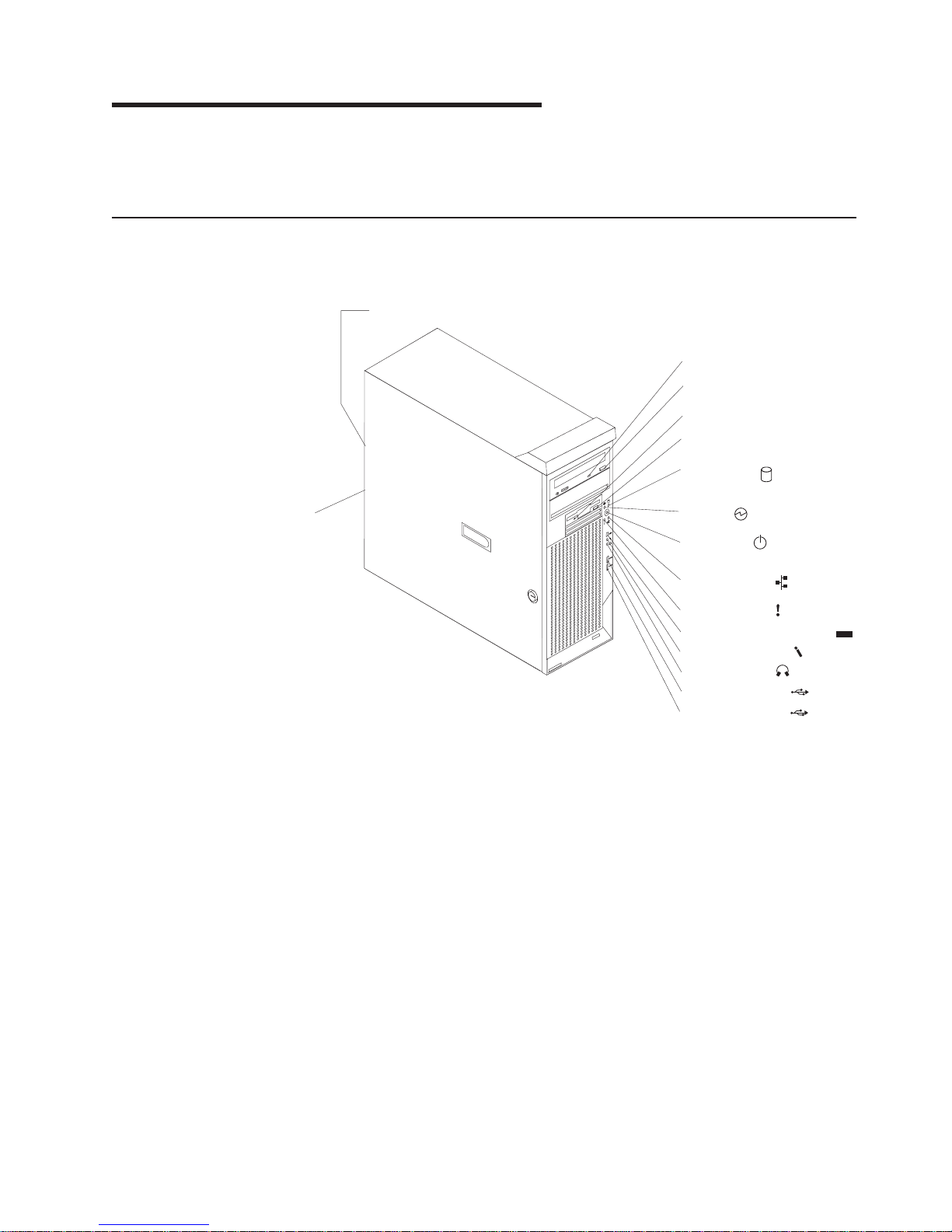
Controls and indicators
This section identifies the controls and indicators on the front and rear of your
computer.
Ethernet link status LED
CD-ROM drive
activity LED
CD-eject
button
Diskette drive
activity LED
Diskette-eject
button
Hard disk drive
activity LED
Ethernet
transmit/receive
activity LED
CD-eject button
Press this button to release a CD from the CD-ROM drive.
CD-ROM drive activity LED
When this LED is lit, it indicates that the CD-ROM drive is in use.
Diskette drive activity LED
When this LED is lit, it indicates that the diskette drive is in use.
Diskette-eject button
Press this button to release a diskette from the diskette drive.
Ethernet link status LED
This LED is on the Ethernet connector on the back of the computer. When
this LED is lit, it indicates that there is an active connection on the Ethernet
port.
Powe r-on
4
9
3
1
LED
Power-control
button
Ethernet transmit/
receive activity LED
System error LED
IEEE 1394 (FireWire) connector
Microphone connector
Line out connector
USB port A connector
USB port B connector
1394
Ethernet transmit/receive activity LED
Hard disk drive activity LED
© Copyright IBM Corp. 2002 9
When this LED is lit, it indicates that there is activity between the computer
and the network. There are two Ethernet transmit/receive activity LEDs: one
on the front bezel and the other on the Ethernet connector on the rear of
the computer.
When this LED is flashing, it indicates that a hard disk drive is in use.
Page 32

IEEE 1394 (FireWire) connector (some models)
This connector is used to connect IEEE 1394 devices to your computer.
Line-out connector (green)
This connector sends stereo audio signals from the computer to external
devices, such as speakers with built-in amplifiers, headphones, or the audio
line-in jack on a stereo system.
Microphone connector (pink)
This connector is used to connect a microphone to record voice or other
sounds on the hard disk. You can also use this connector (and a
microphone) with speech recognition software.
Power-control button
Press this button to turn the computer on and off manually. You can install a
circular disk, called the power-control button shield, over the power-control
button to prevent accidental manual power-off. This disk is provided with
your computer.
Power-on LED
When this LED is lit and does not flash, it indicates that the computer is
turned on. When this LED is flashing, it indicates that the computer is off
and still connected to an ac power source (standby mode).
System error LED
When this LED is lit, it indicates that a system error has occurred. An LED
on the system board might also be lit to help isolate the error. See
“System-board error LEDs” on page 85 and Chapter 5, “Solving problems”
on page 61 for additional information.
USB ports
Use these automatically configures ports to connect universal serial bus
(USB) v2.0 devices to your computer, using Plug and Play technology.
Turning on the computer
When the computer is connected to an ac power source but is not turned on, the
operating system does not run, and all core logic is shut down; however, the
computer can respond to remote requests to turn on the computer. The power-on
LED flashes to indicate that the computer is connected to an ac power source but is
not turned on (standby mode).
Notes:
1. Turn on all external devices, such as the monitor, before turning on the
computer.
2. The power-on LED on the front of the computer is lit when the computer is on
and while it is powering-up.
3. You can install a circular disk over the power-control button to prevent
accidental manual power-off. This disk, known as the power-control button
shield, comes with your computer.
Approximately 20 seconds after the computer is connected to ac power, the
power-control button becomes active, and you can turn on the computer and start
the operating system by pressing the power-control button. The computer can also
be turned on in any of the following ways:
v If a power failure occurs while the computer is turned on, the computer will
restart automatically when power is restored.
10 IBM IntelliStation Z Pro Type 6221: User’s Guide
Page 33

v When you plug in your computer for the first time, Wake on LAN can turn on the
computer.
v If your computer was previously turned on, it must be properly turned off for the
Wake on LAN feature to turn on the computer.
What you see and hear when you start your computer depends on the features that
are installed and the settings in the Configuration/Setup Utility program.
If power-on self-test (POST) detects a problem, there might be a series of beeps or
no beep, and a numeric error message might appear on the screen. Write down
any beep series and error code numbers with descriptions, and then see
“Troubleshooting charts” on page 78 for the explanation of error codes.
During startup, the following messages might be displayed briefly:
v To start the Product Recovery Program, Press F11
v Press F1 for Configuration/Setup
v <<< Press <CTRL><C> to start LSI Logic Configuration Utility >>>
To use any of these features, press the appropriate function key or keys quickly.
The messages appear for only a few seconds. For more information about the
programs listed in these messages, see “Using the Configuration/Setup Utility
program” on page 21, “Using the LSI Logic Configuration Utility program” on page
24, and “Recovering your operating system and preinstalled software” on page 86.
During startup, you might not see Press F1 for Configuration/Setup. If you want
to see the prompt, see instructions for displaying the prompt in “Using the
Configuration/Setup Utility program” on page 21.
Use the Configuration/Setup Utility program to configure your computer with
passwords, PCI adapter configuration, and other options. The Configuration/Setup
Utility menu is displayed at the top of the screen. To navigate the menu and screen
items, follow the instructions on the right of the screen.
The operating system and application programs start from the hard disk. If your
computer is attached to a network, the computer will begin attaching to any LANs
and remote applications to which you have access. A network administrator can
also “wake up” your computer (start it remotely) to download programs or gather
information about computer performance. For more information, see “Wake on LAN”
on page 18.
Using preinstalled software
This section contains information to assist you in setting up the preinstalled
Microsoft operating system and describes how to use the programs that come with
your computer.
Running the operating system setup program
If you are starting your computer for the first time, the Microsoft Windows setup
program runs automatically when you start the computer. The program will prompt
you to make choices or type information. If you need more detailed information than
is provided in this User’s Guide, see your Microsoft operating-system manual.
Chapter 2. Operating your computer 11
Page 34

Important:
1. After turning on your computer for the first time, you must complete the
operating system setup procedure before turning off your computer; otherwise,
unexpected results might occur.
2. The setup program might be slightly different from the one described in your
operating-system manual. Some choices do not appear because they are
preset.
3. During the setup procedure, you must indicate that you accept the license
agreement.
4. The Microsoft registration information will already be displayed in the registration
field. If the Product ID number is not already displayed, you must type it. The
Product ID is on a label attached to the computer.
You will need the following information to complete the setup program:
v The Microsoft documentation that comes with your computer.
v Network information from your network administrator, if your computer is being
connected to a network.
v The printer model and port, if a printer is attached directly to your computer.
After the setup procedure finishes and the computer restarts, the Windows desktop
opens. Your computer is now ready for use.
Installing other operating systems
Your computer comes with Microsoft Windows XP Professional preinstalled. To
install another operating system, follow the instructions in the documentation
provided with the operating system.
If you are installing another Microsoft Windows operating system, follow the
instructions in the readme file on the Device Drivers and IBM Enhanced Diagnostics
CD to install the device drivers. If you install other than a Microsoft Windows
operating system, you might need additional software or device drivers.
Note: If you experience problems with the device drivers installed from the Device
Drivers and IBM Enhanced Diagnostics CD, you can obtain the latest device
drivers at http://www.ibm.com/pc/support/ on the World Wide Web.
Before installing any operating system, be sure you obtain the latest updates.
Contact the operating system manufacturer or, if applicable, check the
manufacturer’s World Wide Web site to obtain the updates.
Additional information about operating systems is posted periodically at
http://www.ibm.com/pc/support/ on the World Wide Web.
Viewing the license agreement
The IBM International License Agreement for Non-Warranted Programs is viewable
through Access IBM. Use of your computer signifies acceptance of this agreement.
Complete the following steps to view the license agreement:
1. Click start.
2. Click Access IBM.
3. Click How do I....
4. Click Solve problems.
5. Click IBM International License Agreement.
12 IBM IntelliStation Z Pro Type 6221: User’s Guide
Page 35

Registering your computer
Registering your computer helps IBM provide better service to you. When IBM
receives your registration information, it is placed into a central technical support
database. If you need technical assistance, the technical-support representative will
have information about your computer. In addition, comments about your computer
are reviewed by a team dedicated to customer satisfaction and are taken into
consideration in making improvements to IBM computers. Use one of the following
methods to register your computer:
v Double-click the IBM Registration icon on the Windows desktop, and then follow
the instructions.
v Register your computer through Access IBM:
1. Click start.
2. Click Access IBM.
3. Click How do I....
4. Click Get started.
5. Click Registering your IBM Computer, and then follow the instructions in
the window.
v Register your computer at http://www.ibm.com/pc/register/ on the World Wide
Web.
Note: If you use the registration program that starts through Access IBM or the
IBM Registration icon on the Windows desktop, you can print the
registration information and provide a mailing address if you do not have
access to the Internet.
Using Access IBM
Access IBM is an interface through which you can quickly access information or
perform specific tasks.
The choices available from the Access IBM Welcome window are:
v How do I...
Select this choice to display information about tasks that are typically performed
immediately after you install a new computer, such as personalizing your
computer to fit your needs, protecting your data, using recovery tools, upgrading
your computer hardware, purchasing IBM services, purchasing IBM options,
solving problems, and viewing the IBM International License Agreement for
Non-Warranted Programs.
v Tools & Tips
Select this choice to display information about Access Support, AntiVirus tools,
data backup and restore tools, configuration backup and restoration tools,
diagnostic programs, data migration tools, help, online books, system information
and personalization, and updates.
v On the Web
Select this choice to display information about obtaining additional information
and support on the World Wide Web.
Complete the following steps to use Access IBM:
1. Double-click the Access IBM icon on the Windows desktop. If the Access IBM
icon is not available on your desktop, click start → All Programs → IBM
Information → Access IBM.
Chapter 2. Operating your computer 13
Page 36

2. Click one of the tabs on the Access IBM Welcome window (for example, How
do I...).
3. Click a topic.
Creating an emergency recovery-repair diskette
At your earliest opportunity, create a recovery-repair diskette and store it in a safe
place. In the unlikely event that your Windows desktop becomes unusable, you can
use the recovery-repair diskette to access the Product Recovery program.
Additional information about the diskette is in Access IBM. For information about
using this diskette, see “Using the emergency recovery-repair diskette” on page 87.
Complete the following steps to create a recovery-repair diskette:
1. From Access IBM, click the How do I... tab; then, click Protect data.
2. Click Creating emergency diskettes.
3. Click Recovery Repair diskette.
4. Follow the instructions on the screen.
Creating an IBM Enhanced Diagnostics diskette
The IBM Enhanced Diagnostics diskette is used to test hardware components on
your computer. See “Using an IBM Enhanced Diagnostics diskette” on page 87 for
instructions on how to use an IBM Enhanced Diagnostics diskette.
You can create an IBM Enhanced Diagnostics diskette using Access IBM, by
downloading a program image from the World Wide Web, or from the Device
Drivers and IBM Enhanced Diagnostics CD.
Complete the following steps to create the diagnostics diskette using Access IBM:
1. From the Access IBM Welcome window, click How do I...; then, click Protect
data.
2. Click Creating emergency diskettes.
3. Click Diagnostic diskette.
4. Follow the instructions on the screen.
Complete the following steps to create a startable IBM Enhanced Diagnostics
diskette from the World Wide Web:
1. Go to http://www.ibm.com/pc/support/ on the World Wide Web.
2. Download the diagnostics file for your computer to a hard disk directory (not to
a diskette).
3. Go to a DOS prompt and change to the directory where the file was
downloaded.
4. Insert a blank, high-density diskette into diskette drive A.
5. Type filename a:
where filename is the name of the file you downloaded from the Web, and press
Enter.
The downloaded Web file is self-extracting and will be copied to the diskette. When
the copy completes, store the diskette in a safe place.
Complete the following steps to create an IBM Enhanced Diagnostics diskette from
the Device Drivers and IBM Enhanced Diagnostics CD:
1. Insert a formatted, blank, high-density diskette into diskette drive A.
14 IBM IntelliStation Z Pro Type 6221: User’s Guide
Page 37

2. Insert the Device Drivers and IBM Enhanced Diagnostics CD into the CD-ROM
drive.
3. At the command prompt, switch to the CD-ROM drive letter. For example, type
e: (where e is the CD-ROM drive letter), and press Enter.
4. Change to the PCDR directory. Type, cd pcdr and press Enter.
5. Type makediag and press Enter.
6. Follow the instructions on the screen to create the diskette.
Using video features
Your computer has an accelerated graphics port (AGP) graphics adapter that
renders 2D or 3D image quality and uses standard video protocol for displaying text
and graphic images on a monitor screen. The adapter supports a variety of video
modes. Video modes are different combinations of resolution, refresh rate, and color
defined by a video standard for displaying text or graphics.
Video device drivers
To take full advantage of the graphics adapter in your computer, some operating
systems and application programs require custom video device drivers. These
device drivers provide greater speed, higher resolution, more available colors, and
flicker-free images.
Device drivers for the graphics adapter and a readme file with instructions for
installing the device drivers are provided on the Device Drivers and IBM Enhanced
Diagnostics CD that comes with your computer and in the ibmtools\drivers directory
on the hard disk. Use the device-driver installation instructions if you need to
reinstall the device drivers or if you need information about obtaining and installing
updated device drivers. For more information about installing device drivers, see
“Recovering or installing device drivers” on page 87.
Changing monitor settings
To get the best possible image on your screen and to reduce flicker, you might
need to reset the resolution and refresh rate of your monitor. You can view and
change monitor settings through your operating system using the instructions in the
readme files on the Device Drivers and IBM Enhanced Diagnostics CD or in the
c:\IBMTools\drivers\ directory on the hard disk of your computer. See your
operating-system documentation for more information about monitor settings.
Attention: Before changing monitor settings, review the documentation that
comes with your monitor. Using a resolution or refresh rate that is not supported by
your monitor might cause the screen to become unreadable and could damage the
monitor. The information that comes with your monitor usually includes resolution
and screen refresh rates that your monitor supports. If you need additional
information, contact the manufacturer of the monitor.
If you are using a cathode ray tube (CRT) monitor, set your monitor for the highest
noninterlaced refresh rate that the monitor supports. If your monitor complies with
the Video Electronics Standards Association (VESA) display data channel (DDC)
standard, it is probably already set to the highest refresh rate the monitor and video
controller can support. If you are not sure whether your monitor is DDC-compliant,
see the documentation provided with the monitor.
Chapter 2. Operating your computer 15
Page 38

If you are using a flat-panel monitor, the refresh rate does not have to be set to the
highest noninterlaced refresh rate that the monitor supports. Flat-panel monitors
produce flicker-free images even when they are operating at a minimum 60 Hz
noninterlaced rate.
If you have a dual-monitor video adapter, see the video adapter device driver
readme file and documentation for more information about enabling dual-monitors.
Using audio features
Your computer has an integrated audio controller that is compatible with the
Microsoft Windows Sound System. Your computer also has a single internal
speaker and three types of audio connectors. Using the audio controller, you can
record and play back sound and music to enhance multimedia applications.
Optionally, you can connect amplified speakers to the line-out connector to provide
improved sound with multimedia applications.
The audio connectors in your computer are 3.5 mm (0.125-in.) mini-jacks. For the
location of the audio connectors, see “Input/output connectors” on page 55.
Microphone (pink)
This connector is used to connect a microphone to record voice or other
sounds on the hard disk (mono input for microphone). With a microphone
attached, you can also use speech recognition software. Microphone
connectors are on both the front and the rear of the computer.
Line in (blue)
This connector receives stereo audio signals from external devices, such as
the line output from a stereo, television, or a musical instrument. One line-in
connector is on the rear of the computer.
Line out (green)
This connector sends stereo audio signals from the computer to external
devices, such as speakers, headphones, or the audio line-in connector on a
stereo system. The internal speaker on the computer is disabled when any
devices are attached to this connector. Line-out connectors are on both the
front and the rear of the computer. Connecting devices to the front line-out
connector disables the rear line-out connector.
Using security features
To deter unauthorized use of your computer, you can use anti-intrusion features and
other security features that are provided with your computer.
Anti-intrusion features
IBM anti-intrusion features help protect against the theft of computer components,
such as the microprocessor, system memory modules, or disk drives.
A cover lock is built into your computer to prevent the cover from being removed.
Two identical keys for the cover lock are also supplied. A tag attached to the keys
has the key serial number and the address of the key manufacturer.
Important: Keep the key-code number and manufacturer address and phone
16 IBM IntelliStation Z Pro Type 6221: User’s Guide
number in a safe place. Because locksmiths are not authorized to
duplicate cover-lock keys, you must order replacement keys from the
key manufacturer. You will need the key code when ordering
replacement keys.
Page 39

You can set the chassis-intrusion detector switch inside the computer to alert the
network system administrator each time the computer cover is removed. For more
information about setting the chassis-intrusion alert, see Chapter 3, “Configuring
your computer” on page 21.
Component protection
Your computer has individual component serial numbers that can be registered with
a security company. You can also register the entire computer. By registering
computer components, you can improve the chances of identifying the components
if they are ever stolen and recovered. For more information about component
registration, go to the IBM Support page at
http://www.ibm.com/pc/us/desktop/assetid/ on the World Wide Web.
Data protection
You can lose data from the hard disk for a variety of reasons. Security violations,
viruses, or hard disk drive failures can all contribute to data loss. To help protect
against the loss of valuable information, IBM has incorporated the following
data-saving features in your computer.
SMART hard disk drive
Your computer comes with a self-monitoring and reporting technology (SMART)
hard disk drive that is enabled to report potential hard disk failures. If an error is
detected, a DMI-compliant warning message is sent to the monitor screen and, if
the computer is part of a network, to an administrator console. When an error is
detected, the data on the hard disk can be backed up and the drive replaced.
Virus protection
Your computer has built-in virus protection that can be enabled through the
Configuration/Setup Utility program. This built-in protection checks for viruses in the
boot record only. Also, Norton AntiVirus for IBM is available on the hard disk.
Integrated RAID capability
The integrated SCSI controller with RAID capabilities in your computer supports
redundant array of independent disks (RAID). You can use the LSI Logic
Configuration Utility program built into your computer to configure RAID level 1
(mirroring) for a single pair of attached devices.
Locking the keyboard
You can lock the keyboard so that others are unable to use it. If a user password is
set using the Configuration/Setup Utility program, the keyboard is locked when you
turn on the computer. You must type the password before the keyboard will unlock.
You can enable the user password feature with the Configuration/Setup Utility
program see “Using passwords” on page 24.
Some operating systems have a keyboard and mouse lock-up feature. See the
documentation that comes with your operating system for more information.
Updating system programs
System programs are the basic layer of software built into your computer. They
include the power-on self-test (POST), the basic input/output system (BIOS) code,
and the Configuration/Setup Utility program. POST is a set of tests and procedures
that are performed each time you turn on your computer. BIOS is a layer of
software that translates instructions from other layers of software into electrical
Chapter 2. Operating your computer 17
Page 40

signals that the computer hardware can understand. You can use the
Configuration/Setup Utility program to view and change the configuration and setup
of your computer.
System programs are stored in an electrically erasable programmable read-only
module (EEPROM) on the system board. This is sometimes referred to as flash
memory.
IBM occasionally makes changes and enhancements to the system programs.
When updates are released, they are available as downloadable files on the World
Wide Web (see Appendix A, “Getting help and technical assistance” on page 93).
You can update system programs by starting your computer using a flash update
diskette or by using the Remote Administration feature, if it is enabled. Instructions
for using system programs updates are included in a readme file provided with the
downloadable files.
Managing your computer
Your computer comes with features that a network administrator or file server can
use to remotely manage and control your computer. The following sections describe
some of these network management tools.
For more detailed information about these tools or to download any of this software,
go to http://www.ibm.com/pc/ on the World Wide Web; then, select your country and
click Go. From the Servers category under the Products column, click Intel
processor-based; then, click Systems Management from the topics on the left.
Scroll down and click on a systems management tool to get more details.
IBM Director Agent
The IBM Director Agent streamlines and automates personal computer (PC)
systems management and support tasks, such as asset deployment and tracking.
These utilities are available for IBM computers at no additional charge, helping to
reduce total cost of ownership of networked computers. IBM Director Agent is
available at http://www.ibm.com/pc/support/ on the World Wide Web.
IBM Director Agent enables you to view detailed information about your computer
hardware and software, set up alerts, monitor a variety of system resources, and
manage your asset security.
Wake on LAN
A network administrator can use the Wake on LAN feature to turn on your computer
from a remote location. When the Wake on LAN feature is used with
network-management software, many functions, such as data transfers, software
updates, and POST or BIOS updates can be performed on many computers
simultaneously.
Remote Administration
A network administrator can use the Remote Administration feature to remotely
update the POST and BIOS code in your computer. Network-management software,
such as Remote Deployment Manager, is required to take advantage of this feature.
Remote Deployment Manager
Remote Deployment Manager is a graphical, server-based program that performs
mass unattended installations of operating systems, software, device drivers, and
18 IBM IntelliStation Z Pro Type 6221: User’s Guide
Page 41

BIOS code updates to remote systems. Used with the Wake on LAN feature,
Remote Deployment Manager can remotely turn on your computer, so that
installations can be done while the computer is not being used.
Software Migration Assistant
Software Migration Assistant (SMA) enables administrators to remotely transfer
configurations, profile settings, printer device drivers, and files from an IBM or
non-IBM computer to supported IBM systems.
Software Delivery Assistant
You can use Software Delivery Assistant to create an image of a single set of
applications that can be deployed to different user-groups while taking into account
the users application needs.
Shutting down your operating system
When you are ready to turn off the computer, use the shutdown procedure for your
operating system to save data and prevent damage to your applications. See your
operating system manual for more information.
If you are using the preinstalled Microsoft Windows XP operating system, complete
the following steps to shut down your operating system and computer:
1. Save and close all files with which you are working.
2. Close all open applications.
3. Click the Windows start button.
4. Click Turn Off Computer; then, click Turn Off to confirm.
Chapter 2. Operating your computer 19
Page 42

Turning off the computer
When you turn off the computer and leave it connected to ac power, the computer
can respond to remote requests to turn on the computer. To remove all power from
the computer, you must disconnect it from the power source.
Some operating systems require an orderly shutdown before you turn off the
computer. See your operating-system documentation for information about shutting
down the operating system.
Statement 5
CAUTION:
The power-control button on the device and the power switch on the power
supply do not turn off the electrical current supplied to the device. The device
also might have more than one power cord. To remove all electrical current
from the device, ensure that all power cords are disconnected from the power
source.
2
1
The computer can be turned off in any of the following ways:
v You can turn off your computer from the operating system. If this feature is
supported by your operating system, it will turn off the computer after performing
an orderly shutdown of the operating system.
To turn off the computer from the Microsoft Windows XP operating system, click
start → Turn Off Computer; then, select Turn Off.
v You can press the power-control button on the front of the computer. If this
feature is supported by your operating system, it will turn off the computer after
performing an orderly shutdown of the operating system.
Note: After turning off the computer, wait at least 5 seconds before you press
the power-control button to turn on the computer again.
v You can press and hold the power-control button for more than 4 seconds to
cause an immediate shutdown of the computer. You can use this feature to turn
off the computer if the operating system stops functioning.
v The computer can turn itself off as an automatic response to a critical system
failure.
20 IBM IntelliStation Z Pro Type 6221: User’s Guide
Page 43

Chapter 3. Configuring your computer
The following configuration programs are available to configure your computer:
v Configuration/Setup Utility program
The Configuration/Setup Utility program is part of the basic input/output system
(BIOS) code that comes with your computer. You can use this program to
configure serial port assignments, change interrupt request (IRQ) settings,
change the device startup sequence, set the date and time, set passwords, and
set the chassis-intrusion alert. See “Using the Configuration/Setup Utility
program”.
v LSI Logic Configuration Utility
With the built-in LSI Logic Configuration Utility program, you can configure the
integrated SCSI controller with RAID capabilities and the devices that are
attached to it. See “Using the LSI Logic Configuration Utility program” on
page 24.
v ServeRAID Manager
The ServeRAID programs come with your computer. If your computer has a
ServeRAID controller installed, or if you are using the integrated SCSI controller
with RAID capabilities as a RAID controller, you must use the ServeRAID
Manager program to define and configure your disk-array subsystem before you
install your operating system. See “Using ServeRAID Manager” on page 25 for
more information.
v Ethernet controller configuration process
To configure the integrated Ethernet controller, see “Configuring the Gigabit
Ethernet controller” on page 26.
Using the Configuration/Setup Utility program
This section provides the instructions for starting the Configuration/Setup Utility
program and descriptions of the menu choices that are available.
Starting the Configuration/Setup Utility program
Complete the following steps to start the Configuration/Setup Utility program:
1. Turn on the computer and watch the monitor screen. If your computer is already
on when you start this procedure, you must shut down the operating system,
turn off the computer, wait a few seconds until all in-use LEDs go off, and
restart the computer.
2. When the message Press F1 for Configuration/Setup appears on the screen
during startup, press F1. (This prompt appears on the screen for only a few
seconds. You must press F1 quickly.)
Note: If you have set both administrator and user passwords, you must type
the administrator password to access the full Configuration/Setup Utility
menu.
3. Follow the instructions that appear on the screen.
© Copyright IBM Corp. 2002 21
Page 44

Configuration/Setup Utility menu choices
From the Configuration/Setup Utility main menu, you can select settings that you
want to change. A typical Configuration/Setup Utility main menu is shown in the
following illustration.
IBM Setup - (c) Copyright IBM Corporation 2002
Configuration/Setup Utility
·
System Summary
·
System Information
·
Devices and I/O Ports
·
Date and Time
·
System Security
·
Start Options
·
Advanced Setup
· PC Health Status
·
Error Logs
Save Settings
Restore Settings
Load Default Settings
Exit Setup·
<F1> Help < > < > Move
<Esc> Exit <Enter> Select
Notes:
1. You can press F1 to display Help information for a selected menu item.
2. The choices on some menus might differ slightly, depending on the BIOS
version in your computer.
The following choices are available from the main menu:
v System Summary
This choice contains general information about your computer, such as a
summary of components and computer configuration. You can view information
about the type and speed of the microprocessor and the amount of memory that
is installed. System summary information appears on both the full and limited
Configuration/Setup Utility menus.
Changes that you make to configuration settings appear on this summary screen.
You cannot edit the fields of the configuration and system information.
v System Information
Select this choice to display information about your computer. Changes that you
make on other menus might appear on this summary screen. You cannot edit
any fields. The System Information choice appears only on the full
Configuration/Setup Utility main menu.
– Product Data
Select this choice to view system information, such as the machine type and
model, the computer serial number, and the revision level or issue date of the
BIOS and diagnostics code stored in the electrically erasable programmable
ROM (EEPROM).
– System Card Data
Select this choice to view information about the system board.
v Devices and I/O Ports
Select this choice to view or change the assignments for devices and
input/output (I/O) ports. This choice appears only on the full Configuration/Setup
Utility main menu.
22 IBM IntelliStation Z Pro Type 6221: User’s Guide
Page 45

You can use this choice also to enable or disable the integrated SCSI controller
with RAID capabilities and Ethernet (LAN) controllers, and standard ports (serial,
parallel, and so on).
– The default setting is Enabled for all the controllers you can control from this
menu. If you select Disabled, the system will not configure the disabled
device and the operating system will not detect the device. (This is equivalent
to unplugging the device.)
– If the integrated SCSI controller with RAID capabilities is disabled and no
SCSI adapter is installed, the computer will have no SCSI capability.
– If the on-board Ethernet controller is disabled and no Ethernet adapter is
installed, the computer will have no Ethernet capability.
v Date and Time
Use this menu choice to set the system date and time. The system time is in a
24-hour format: hour:minute:second.
v System Security
Select this choice to set a power-on or an administrator password. See “Using
passwords” on page 24 for more information. You also can enable the
chassis-intrusion detector to alert you each time the computer cover is removed.
v Start Options
Select this choice to view or change the start options. Start options take effect
when you start your computer. You can designate keyboard operating
characteristics, such as the keyboard speed, or specify whether the computer
starts with the keyboard number lock on or off.
The computer uses a startup sequence to determine the device from which the
operating system starts. For example, you can define a startup sequence that
checks for a startable diskette in the diskette drive; then, checks the hard disk
drive, and then checks a network adapter. You can enable a virus-warning test
that checks for changes in the master boot record at startup. You also can
choose to run POST in the quick mode, or read the microprocessor serial
number.
v Advanced Setup
Select this choice to change values for advanced hardware features, such as
Cache Control and PCI configuration.
A message displays above the choices on this menu to alert you that the system
might malfunction if these options are configured incorrectly. Follow the
instructions on the screen carefully.
– Power Management Setup
Select this choice to enable or disable system power settings. This includes
automatic power-on settings such as Wake on LAN.
– Chipset Feature
Select this choice to modify settings that control features of the core chip set
on the system board.
Attention: Do not make changes to the Chipset Feature unless directed to
do so by an IBM authorized service representative.
– Processor Control
Select this choice to enable or disable the microprocessor cache and
hyper-threading.
Attention: Do not make changes to the Processor Control unless directed
to do so by an IBM authorized service representative.
Chapter 3. Configuring your computer 23
Page 46

v PC Health Status
v Error Logs
v Save Settings
v Restore Settings
v Load Default Settings
v Exit Setup
Using passwords
You can use any combination of up to seven characters (A–Z, a–z, and 0–9) for the
user (power-on) password or the administrator password. When you have set one
or both of the passwords, record the passwords and keep them in a secure place.
Select this choice to display the computer temperature and voltage status, and
fan speeds.
Select POST Error Log to view the three most recent error codes and messages
that the system generated during POST.
Select Clear event/error logs from the POST Error Log menu to clear the
POST Error Log.
Select this choice to save your customized settings.
Select this choice to delete your changes.
Select this choice to cancel your changes.
If you have made any changes and not saved them, the program will prompt you
to save the changes or exit without saving the changes.
If both a user and administrator password are set, you can type either password at
the password prompt that appears as you start your computer. However, if you want
to change the settings in the Configuration/Setup Utility program, you must type the
administrator password to access the full configuration menus. If you type the user
password, you can only view limited information in the Configuration/Setup Utility
program.
Keep a record of your password in a secure place. If you forget the user or
administrator password, you can regain access to the computer through one of the
following methods:
v If you have forgotten the user password and an administrator password is set,
type the administrator password at the power-on prompt. Start the
Configuration/Setup Utility program and change the user password.
v Clear CMOS settings by changing the position of the CMOS recovery jumper
(JBAT1). See “Erasing a lost or forgotten password (clearing CMOS)” on page 89
for instructions.
v Remove the battery and then install the battery. See “Replacing the battery” on
page 90 for instructions.
Using the LSI Logic Configuration Utility program
LSI Logic Configuration is a built-in, menu-driven configuration utility program that
you can use to:
v Perform a low-level format of a SCSI hard disk drive
v Set a SCSI device scan order
v Set a SCSI ID for a controller
24 IBM IntelliStation Z Pro Type 6221: User’s Guide
Page 47

Notes:
1. The integrated SCSI controller with RAID capabilities in your computer supports
redundant array of independent disks (RAID). You can use the LSI Logic
Configuration Utility program built into your computer to configure RAID level 1
for a single pair of attached devices.
2. If you install a different type of RAID adapter in your computer, use the
configuration method supplied with the RAID adapter to view or change SCSI
settings for attached devices.
The following sections provide the instructions needed to start the LSI Logic
Configuration Utility program and to format a SCSI hard disk drive.
Starting the LSI Logic Configuration Utility program
Complete the following steps to start the LSI Logic Configuration Utility program:
1. Turn on the computer.
2. When the <<< Press <CTRL><C> to start LSI Logic Configuration Utility
>>> prompt appears, press Ctrl+C. If an administrator password has been set,
you are prompted to type the password to start the LSI Logic Configuration
Utility program.
3. Use the arrow keys to select a controller (channel) from the list of adapters;
then, press Enter.
4. Follow the instructions on the screen to change the settings of the selected
items; then, press Enter. The Device Properties and Mirroring Properties
choices produce additional screens of parameters to review or change.
Formatting a SCSI hard disk drive
Low-level formatting removes all data from the hard disk. If there is data you want
to save, back up the hard disk before performing this procedure. Complete the
following steps to format a drive.
Note: Before you format a SCSI hard disk, make sure that it is not part of a
mirrored pair. From the list of adapters, select the controller (channel) for the
drive to format. Select Mirroring Properties and make sure the mirroring
value for the drive is set to None.
1. From the list of adapters, select the controller (channel) for the drive to format.
2. Select Device Properties.
3. Use the arrow keys (↑ or ↓) to highlight the drive to format.
4. Use the arrow keys (← or →) or the End key to scroll to the right.
5. Select the Format; then, press Enter to begin the low-level formatting operation.
Using ServeRAID Manager
You can use the ServeRAID Manager program, provided on the IBM ServeRAID
Support CD, to:
v Configure a redundant array of independent disks (RAID)
v Restore a SCSI hard disk to factory-default settings, erasing all data
v View your RAID configuration and associated devices
v Monitor operation of your RAID controllers
The ServeRAID Manager program operates in two ways:
v Startable-CD mode
Chapter 3. Configuring your computer 25
Page 48

v As an installed software program
See the ServeRAID documentation on the IBM ServeRAID Support CD for
additional information about RAID technology and instructions for using ServeRAID
Manager. The Installation Guide for your computer also contains instructions for
using ServeRAID Manager to configure your integrated SCSI controller with RAID
capabilities.
Attention:
1. When setting up RAID mirroring, you must set the hard disk drive containing the
operating system as the primary drive. Failure to do so will erase the operating
system and applications that came pre-installed on your computer.
2. Installing an optional RAID adapter in your computer will require that you reload
the operating system and applications.
Notes:
1. The integrated SCSI controller with RAID capabilities in your computer supports
only RAID level 1.
2. If you install a different type of RAID adapter in your computer, use the
configuration method supplied with the RAID adapter to view or change SCSI
settings for attached devices.
Before you install your operating system, you must configure the controller that is
attached to the hard disk drives. You must use the configuration program on the
IBM ServeRAID Support CD to configure the integrated SCSI controller with RAID
capabilities or to configure an optional IBM ServeRAID controller.
Notes:
™
1. You cannot use the ServerGuide
Setup and Installation CD to configure the
optional controllers.
2. To update the firmware and BIOS for an optional ServeRAID controller, you
must use the IBM ServeRAID Support CD that comes with the ServeRAID
option.
Configuring the Gigabit Ethernet controller
The Ethernet controller is integrated on the system board. It provides an interface
for connecting to a 10-Mbps, 100-Mbps, or 1000-Mbps network and provides full
duplex (FDX) capability, which enables simultaneous transmission and reception of
data on the network. If the Ethernet port in the computer supports auto-negotiation,
the controller detects the data-transfer rate of the network (10BASE-T,
100BASE-TX, or 1000BASE-T) and automatically operates at that rate, in
full-duplex or half-duplex mode, as appropriate. The Ethernet controller supports
optional modes, such as teaming, priority packets, load balancing, fault tolerance,
and virtual LANs, which provide better performance, security, and throughput. These
modes apply to the integrated Ethernet controller and to controllers on supported
Ethernet adapters.
You do not need to set any jumpers or configure the controller. However, you must
install a device driver to enable the operating system to address the controller. The
device drivers are available on the Device Drivers and IBM Enhanced Diagnostics
CD. For the latest device drivers and information about configuring your Ethernet
controller, go to the IBM Support Web site at http://www.ibm.com/pc/support.
26 IBM IntelliStation Z Pro Type 6221: User’s Guide
Page 49

Chapter 4. Installing options
This chapter provides instructions for installing or replacing options in your
computer. For a list of supported options for your computer, go to
http://www.ibm.com/pc/ on the World Wide Web; then, select your country and
navigate to the list of options for your computer.
Installation guidelines
Before you begin installing options in your computer, read the following information:
v Review the safety information beginning on page vii, “Installation guidelines”, and
“Handling static-sensitive devices” on page 28. These guidelines will help you
work safely with your computer and options.
v Make sure that you have an adequate number of properly grounded electrical
outlets for your computer, monitor, and other devices that you will connect to the
computer.
v Back up all important data before you make changes to disk drives.
v Have a small flat-blade screwdriver available.
v When you need to access the inside of the computer to install options, you might
find it easier to lay the computer on its side. Before laying the computer on its
side, rotate the two front stabilizing feet a quarter turn inward toward the
computer, so that they do not break. Before returning the computer to an upright
position, rotate the front stabilizing feet a quarter turn outward from the computer.
See “Moving the stabilizing feet” on page 30 for more information.
v The blue color on components and labels identifies touch points where you can
grip a component, move a latch, and so on.
v For a list of supported options for your computer, go to http://www.ibm.com/pc/ on
the World Wide Web; then, select your country and navigate to the list of options
for your computer.
System reliability considerations
To help ensure proper system cooling and system reliability, make sure that:
v Each of the drive bays has a drive or a filler panel and electromagnetic
compatibility (EMC) shield installed.
v There is adequate space around the computer to allow the computer cooling
system to work properly. Leave approximately 50 mm (2 in.) of open space
around the front and rear of the computer. Do not place objects in front of the
fans. For proper cooling and airflow, replace the computer cover before turning
on the computer. Operating the computer for extended periods of time (over 30
minutes) with the computer cover removed might damage computer components.
v You have followed the cabling instructions that come with optional adapters.
v You have replaced a failed fan as soon as possible.
v Do not remove the air baffle when the computer is operational. Operating the
computer without the air baffle might cause the microprocessor to overheat.
v Microprocessor socket 2 always contains either a microprocessor baffle or a
microprocessor and heatsink.
© Copyright IBM Corp. 2002 27
Page 50

Handling static-sensitive devices
Attention: Static electricity can damage electronic devices, including your
computer. To avoid damage, keep static-sensitive devices in their static protective
packages until you are ready to install them.
To reduce the possibility of damage from electrostatic discharge, observe the
following precautions:
v Limit your movement. Movement can cause static electricity to build up around
you.
v Handle the device carefully, holding it by its edges or its frame.
v Do not touch solder joints, pins, or exposed circuitry.
v Do not leave the device where others can handle and damage it.
v While the device is still in its static-protective package, touch it to an unpainted
metal part of the computer for at least 2 seconds. This drains static electricity
from the package and from your body.
v Remove the device from its package and install it directly into the computer
without setting down the device. If it is necessary to set down the device, put it
back into its static-protective package. Do not place the device on your computer
cover or on a metal surface.
v Take additional care when handling devices during cold weather. Heating reduces
indoor humidity and increases static electricity.
Major components of the computer
The following illustration shows the major components in the computer.
Rear adapterretention bracket
Memory modules
Microprocessor 1
Microprocessor 2
Air baffle
Support bracket
Side cover
System board
4
9
3
1
Drive cage
Front adapterretention bracket
EMC
shield
Filler
panel
28 IBM IntelliStation Z Pro Type 6221: User’s Guide
Key lock
Page 51

System-board option connectors
The following illustration shows the system-board connectors for user-installable
options.
Microprocessor 1
(CPU1)
Microprocessor 2
(CPU2)
AGP Pro slot
PCI slot 1
(PCI1)
PCI-X slot 2
(PCI2)
PCI-X slot 3
(PCI3)
PCI-X slot 4
(PCI4)
PCI-X slot 5
(PCI5)
System-board internal connectors
DIMM 1
DIMM 2
DIMM 3
DIMM 4
Battery
IEEE 1394
(FireWire)
adapter
Mini-PCI
type III slot 6
(PCI6)
The following illustration shows the internal connectors on the system board.
Diskette
drive (FDD1)
Rear fan 1
(SYSFAN1)
Ethernet
activity LED
(JFR1)
Rear fan 2
(SYSFAN2)
CD audio
(JCD1)
Main power
(POWER1)
Powe r
(POWER2)
SCSI LED
(J18)
Secondary IDE
(IDE2)
Primary IDE
(IDE1)
Error LED
(JER2)
Cover switch
(JCI2)
Internal speaker
(JSPK1)
Front panel
switch/LEDs
(JFP1)
SCSI
channel A
(SCSI1)
SCSI
channel B
(SCSI2)
Chapter 4. Installing options 29
Page 52

System-board external connectors
The following illustration shows the external input/output port connectors on the
system board.
Mouse
Keyboard
USB 1/
USB 2
Parallel
(LPT1)
Serial A/
Serial B
(COMA/
COMB)
Ethernet
Audio
Front panel audio (J15)
Installing options
This section provides instructions for installing hardware options in your computer.
Moving the stabilizing feet
The two front feet on the bottom of the computer rotate 90 degrees to provide
additional stability.
When installing options in the computer, you might find it easier to lay the computer
on its side. If you do so, rotate the feet in towards the computer, so they do not
break off due to the weight of the computer.
Front panel USB (JUSB3)
30 IBM IntelliStation Z Pro Type 6221: User’s Guide
Page 53

Removing the side cover
To remove the side cover, you might find it easier to lay the computer on its side. If
you do, move the stabilizing feet so that they do not break (see “Moving the
stabilizing feet” on page 30).
Complete the following steps to remove the side cover of the computer:
1. Review the safety information beginning on page vii.
2. Turn off the computer and all attached devices (see “Turning off the computer”
on page 20).
3. Disconnect all power cords; then disconnect all external cables.
4. Unlock the side cover; then, pull the cover release latch away from the
computer, and push the cover toward the rear of the computer. Lift the side
cover off the computer and set it aside.
4
9
3
1
For instructions for replacing the side cover, see “Replacing the side cover” on
page 53.
Attention: For proper cooling and airflow, replace the cover before turning on the
computer. Operating the computer with the cover removed might damage computer
components.
Chapter 4. Installing options 31
Page 54

Removing the bezel
When working with some devices, such as the diskette drive, you must first remove
the bezel to access the device.
Complete the following steps to remove the bezel:
1. Remove the side cover (“Removing the side cover” on page 31).
2. Locate the bezel-release lever; then, press the bezel-release lever toward the
front of the computer.
3. Pull the top of the bezel away from the chassis; then, push the bezel down to
disengage the bottom tabs.
4. Remove the bezel from the computer and store the bezel in a safe place.
4
9
3
1
For instructions for replacing the bezel, see “Replacing the bezel” on page 52.
32 IBM IntelliStation Z Pro Type 6221: User’s Guide
Page 55

Removing and installing the support bracket
When working with some devices, such as hard disk drives, adapters, and memory
modules, you must first remove the support bracket to access the device.
Complete the following steps to remove the support bracket:
1. Remove the side cover (“Removing the side cover” on page 31).
2. Pull out on the rear end of the support bracket approximately 150 mm (6 in.).
3. Disengage the front end of the support bracket from the computer and set the
bracket aside.
4
9
3
1
To reinstall the support bracket, reverse the previous steps.
Working with adapters
Your computer comes with adapter connectors or slots. The AGP video adapter is
installed in the AGP Pro slot, and some models have an IEEE 1394 (FireWire)
adapter installed in mini-PCI slot 6 (PCI6). You can install up to five additional
optional adapters in your computer in PCI slot 1 (PCI1) and PCI-X slots 2 through 5
(PCI2 through PCI5).
See “System-board option connectors” on page 29 for the locations of expansion
slots on the system board.
Adapter considerations
Before you install an adapter, review the following information:
v Read the documentation that comes with your operating system.
v Locate the documentation that comes with the adapter and follow those
instructions in addition to the instructions in this chapter. If you need to change
the switch or jumper settings on your adapter, follow the instructions that come
with the adapter.
v You can install only a 32-bit adapter in the 32-bit PCI slot 1; 64-bit adapters can
be installed only in the 64-bit PCI-X slots 2 through 5.
Chapter 4. Installing options 33
Page 56

v You can install full-length adapters in all five expansion slots; however, full-length,
double-width adapters will not fit in slot 5 and are not supported. None of the
expansion slots are hot-plug.
v The 32-bit PCI slot 1 supports 5.0 V signaling PCI adapters; it does not support
3.3 V signaling adapters or 64-bit adapters.
v The 64-bit PCI-X slots 2 through 5 support 3.3 V signaling PCI or PCI-X
adapters; they do not support 5.0 V signaling adapters.
v The PCI bus configuration is as follows:
– The 32-bit PCI slot 1 and mini-PCI slot 6 (for the IEEE 1394 controller) are on
the 33 MHz PCI bus.
Note: If your computer did not come with a IEEE 1394 (FireWire) adapter
installed in mini-PCI slot 6, do not install an adapter in this slot. It is not
supported.
– The 64-bit PCI-X slots 2 and 3 and the integrated Ethernet controller are on
the 100 MHz PCI-X bus, channel A.
– The 64-bit PCI-X slots 4 and 5 and the integrated SCSI controller with RAID
capabilities are on the 100 MHz PCI bus, channel B.
v To provide failover protection, an optional Ethernet adapter can be installed only
in PCI-X slots 2 through 5.
v Installing an optional RAID adapter in your computer will require that you reload
the operating system and applications that came pre-installed on your computer.
v The system scans the AGP slot, mini-PCI slot 6, PCI expansion slot 1, and PCI-X
expansion slots 2 through 5 to assign system resources. Then, the system starts
the PCI devices in the following order, if you have not changed the default
startup sequence: AGP slot, mini-PCI slot 6, PCI expansion slot 1, system-board
integrated drive electronics (IDE) or SCSI devices, and then PCI-X expansion
slots 2 through 5.
v For a list of supported options for your computer, go to http://www.ibm.com/pc/ on
the World Wide Web; then, select your country and navigate to the list of options
for your computer.
Installing an adapter
Note: The AGP Pro slot and PCI slot 1 must be empty for you to access the IEEE
1394 (FireWire) adapter in mini-PCI slot 6. If you are replacing the IEEE
1394 adapter, the optional PCI adapter and the AGP video adapter will need
to be temporarily removed.
Complete the following steps to install an adapter in your computer:
1. Review the safety information beginning on page vii, “Installation guidelines” on
page 27, and “Handling static-sensitive devices” on page 28.
2. Turn off the computer and all attached devices.
3. Disconnect all power cords; then disconnect all external cables.
4. Remove the side cover (see “Removing the side cover” on page 31).
5. Determine which slot you will use for the adapter. Check the instructions that
come with the adapter for any requirements, restrictions, or cabling
instructions. It might be easier to route cables before you install the adapter.
6. Rotate the rear adapter-retention bracket to the open (unlocked) position and
remove it from the computer. Rotate the front adapter-retention bracket to the
open position. If you are installing a smaller adapter, remove only the rear
adapter-retention bracket.
34 IBM IntelliStation Z Pro Type 6221: User’s Guide
Page 57

7. If there is an adapter already installed in the slot, remove it and place it on a
static-protective surface.
If the slot is empty, remove the expansion-slot cover. From the rear of the
computer, press on the slot cover. Grasp it and pull it out of the expansion slot.
Store it in a safe place for future use.
Attention: Expansion-slot covers must be installed on all vacant slots. This
maintains the electronic emissions standards of the computer and ensures
proper ventilation of computer components.
8. Set any jumpers or switches on the adapter or system board according to the
documentation that comes with the adapter.
Attention: Be certain that the adapter is correctly seated in the expansion
slot before you turn on the computer. Incomplete installation of an adapter
might damage the system board or the adapter.
9. Remove the adapter from the static-protective package, carefully grasp the
adapter by the top edge or upper corners, and align it with the expansion slot
guides; then, press the adapter firmly into the expansion slot. Move the
adapter directly from the static-protective package to the adapter slot. Avoid
touching the components and gold-edge connectors on the adapter.
4
9
3
Expansion
slot cover
Rear
adapterretention
bracket
Adapter
Front
adapterretention
bracket
1
10. Connect required cables to the adapter. Route cables so that they do not block
the flow of air from the fans. If you are installing an optional SCSI adapter, see
“Cabling an optional SCSI adapter” on page 36 for additional information.
11. If you have another adapter to install, repeat steps 5 through 10.
12. If you have installed a full-length adapter, rotate the front adapter-support
bracket to the closed (locked) position.
13. Reinstall the rear adapter-retention bracket; then, rotate the bracket to the
closed (locked) position.
Note: If any adapters in your computer are large or have heavy cables
attached to them, you can remove the rear adapter-retention bracket
Chapter 4. Installing options 35
Page 58

and secure all of the adapters with expansion-slot screws. The
expansion-slot screws are stored on the back of the computer next to
slot 1.
14. If you have other options to install, do so now; otherwise, continue with step
15.
15. Replace the support bracket (see “Removing and installing the support
bracket” on page 33).
16. Replace the side cover (see “Replacing the side cover” on page 53).
17. Reconnect the external cables and power cords; then, turn on the attached
devices and the computer.
Cabling an optional SCSI adapter
You can install an optional SCSI adapter in your computer to control the internal
hard disk drives. With a SCSI adapter installed you can configure the internal hard
disk drives into disk arrays. You can also cable a SCSI adapter to external hard
disk drives. See your SCSI adapter option documentation for complete instructions
for installing a SCSI adapter in your computer and for additional information about
SCSI adapters.
Note: An optional SCSI adapter or cable option is required to connect external
SCSI devices.
Complete the following steps to cable an optional SCSI adapter:
1. Install the SCSI adapter (see “Installing an adapter” on page 34).
2. Connect the SCSI-signal cable to the adapter and to one or more of the
signal-cable connectors to the rear of the SCSI devices.
36 IBM IntelliStation Z Pro Type 6221: User’s Guide
Page 59

3. Connect the SCSI-activity-indicator cable to the adapter and to the SCSI-LED
connector (J18) on the system board. See “System-board internal connectors”
on page 29 for the location of the SCSI-LED connector.
SCSI
signal
cable
4
9
3
1
Rear
adapter
retention
bracket
SCSI signal
cable connector
SCSI activity
indicator cable
connector
SCSI
Adapter
SCSI
activity
indicator
cable
Front
adapter
retention
bracket
4. Complete the installation of the optional SCSI adapter.
Chapter 4. Installing options 37
Page 60

Installing internal drives
Depending on your computer model, you might have one or more of the following
drives installed:
v Diskette
v Hard disk
v CD-ROM, CD-RW, or DVD/CD-RW combo
Internal drive bays
Your IntelliStation Z Pro computer comes with an IDE CD-ROM, CD-RW, or
DVD/CD-RW combo drive in bay 1, a 3.5-in., 1.44 MB diskette drive in bay 3, and a
hard disk drive installed in bay 4.
Bay 1
Bay 2
Bay 3
Bay 4
4
9
3
1
Bay 5
Bay 6
Notes:
1. Diskette drives, tape drives, CD-ROM, DVD/CD-RW, and DVD-ROM drives are
examples of removable-media drives. You can install removable-media drives in
bays 1, 2, and 3 only.
2. The integrated IDE controller in your computer supports the connection of up to
four IDE devices.
3. You can install a 3.5-in. slim-high or 5.25-in. half-high removable-media drive,
such as a tape backup, CD-RW, or DVD drive, in bay 2.
4. The IntelliStation Z Pro computer supports only one diskette drive.
5. To install a 3.5-in. drive in a 5.25-in. bay, you must use the 5.25-in. conversion
kit, supplied with the option.
6. The electromagnetic interference (EMI) integrity and cooling of the computer are
protected by having all bays and PCI slots covered or occupied. When you
install a drive or PCI adapter, save the EMC shield and filler panel from the bay
or the PCI adapter slot cover in the event you later remove the option.
38 IBM IntelliStation Z Pro Type 6221: User’s Guide
Page 61

7. For a complete list of supported options for your computer, go to
http://www.ibm.com/pc/ on the World Wide Web; then, select your country and
navigate to the list of options for your computer.
Preinstallation steps
Some of these steps are required only during the initial installation of an internal
drive.
1. Review the safety information beginning on page vii, “Installation guidelines” on
page 27, and the documentation that comes with your drive.
2. Verify that you have all the cables and other equipment specified in the
documentation that comes with the drive.
3. Choose the bay in which you want to install the drive.
4. Check the instructions that come with the drive to see if you need to set any
switches or jumpers on the drive. If you are installing a SCSI device, be sure to
set the SCSI ID for that device.
Installing a drive in bay 2
Complete the following steps to install a drive in bay 2:
1. Follow the instructions in “Preinstallation steps” on page 39.
2. Turn off the computer and all attached devices.
3. Disconnect all power cords; then disconnect all external cables.
4. Remove the side cover (see “Removing the side cover” on page 31).
5. Remove the support bracket (see “Removing and installing the support
bracket” on page 33).
6. Use a screwdriver to pry the filler panel and EMC shield away from the
computer.
Note: If you are installing a drive that contains a laser, observe the following
safety precaution.
Statement 3
CAUTION:
When laser products (such as CD-ROMs, DVD drives, fiber optic devices, or
transmitters) are installed, note the following:
v Do not remove the covers. Removing the covers of the laser product could result in
exposure to hazardous laser radiation. There are no serviceable parts inside the
device.
v Use of controls or adjustments or performance of procedures other than those
specified herein might result in hazardous radiation exposure.
Danger
Some laser products contain an embedded Class 3A or Class 3B laser diode. Note the
following. Laser radiation when open. Do not stare into the beam, do not view directly with
optical instruments, and avoid direct exposure to the beam.
Chapter 4. Installing options 39
Page 62
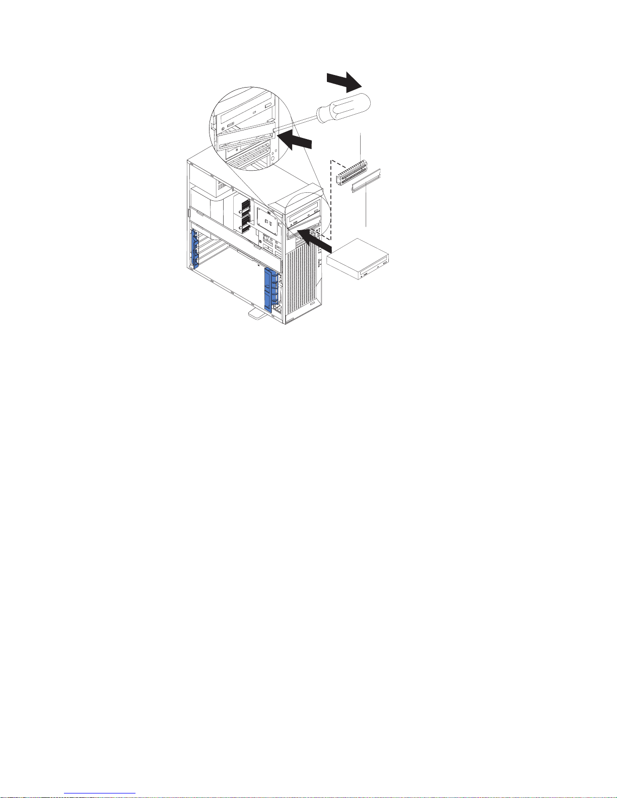
EMC shield
Filler panel
4
9
3
1
7. Touch the static-protective package containing the drive to any unpainted metal
surface on the computer; then, remove the drive from the package and place it
on a static-protective surface.
8. Set any jumpers or switches on the drive according to the documentation that
comes with the drive.
Note: You might find it easier to install the new drive into the appropriate
opening on the front, and then attach the cables.
9. If you are installing a 5.25-in. drive in bay 2, push the drive into the bay; then,
use the two screws to attach the drive to the drive cage. If you are installing a
3.5-in. drive in bay 2, you must attach the 5.25-in. conversion kit, supplied with
your option, to the 3.5-in. drive.
10. Determine whether the drive is an IDE or SCSI device; then, connect one end
of the appropriate signal cable into the back of the drive and make sure that
the other end of this cable is connected into the appropriate IDE or SCSI
connector on the system board. See “Power and signal cables for internal
drives” on page 43 for additional information about cabling drives and
“System-board internal connectors” on page 29 for the location of IDE and
SCSI connectors on the system board. If there are open connectors on the
cables connecting an existing IDE drive, this cable can be used to connect the
new drive. The 3-connector SCSI cable that comes with your computer cannot
be used to connect a SCSI drive in bay 2.
11. Route the signal cable so that it does not block the air flow to the rear of the
drives or over the microprocessor and memory.
12. Connect the power cable to the back of the drive. The connectors are keyed
and can be inserted only one way.
13. If you have other options to install or remove, do so now.
14. Replace the support bracket (see “Removing and installing the support
bracket” on page 33).
15. Replace the side cover (see “Replacing the side cover” on page 53).
40 IBM IntelliStation Z Pro Type 6221: User’s Guide
Page 63

16. Reconnect the external cables and power cords; then, turn on the attached
devices and the computer.
Replacing a diskette drive in bay 3
Complete the following steps to replace a diskette drive in bay 3:
1. Follow the instructions in “Preinstallation steps” on page 39.
2. Turn off the computer and all attached devices.
3. Disconnect all power cords; then disconnect all external cables.
4. Remove the side cover (see “Removing the side cover” on page 31).
5. Remove the bezel (see “Removing the bezel” on page 32).
6. Remove the support bracket (see “Removing and installing the support
bracket” on page 33).
7. Remove the existing drive by disconnecting the cables in the rear of the
diskette drive; then, press on the oval cutout to release the drive and gently
pull it out the front.
8. Remove the retainer from the left side of the diskette drive and place it on the
new diskette drive.
9. Install the diskette drive by sliding the drive into the bay so that the metal tab
of the drive aligns with the oval cutout and the drive locks into place; then,
connect the cables at the rear of the drive.
10. If you have other options to install or remove, do so now.
11. Replace the support bracket (see “Removing and installing the support
bracket” on page 33).
12. Replace the bezel (see “Replacing the bezel” on page 52).
13. Replace the side cover (see “Replacing the side cover” on page 53).
14. Reconnect the external cables and power cords; then, turn on the attached
devices and the computer.
Installing a hard disk drive in bay 4, 5, or 6
Bays 4, 5, and 6 are in the drive cage. The drive cage is behind the front of the
adapter-support bracket.
Note: You might find it useful to work with the computer laying on its side.
Complete the following steps to install a drive in bay 4, 5, or 6:
1. Follow the instructions in “Preinstallation steps” on page 39.
2. Turn off the computer and all attached devices.
3. Disconnect all power cords; then disconnect all external cables.
4. Remove the side cover (see “Removing the side cover” on page 31).
5. Remove the support bracket (see “Removing and installing the support
bracket” on page 33).
Chapter 4. Installing options 41
Page 64
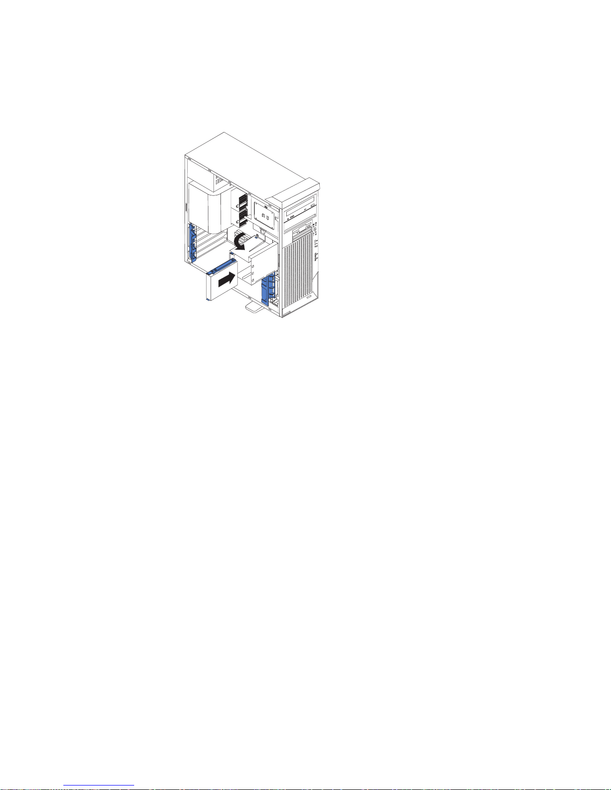
6. Grasp the drive cage and rotate the cage out of the computer until it locks into
place with the drive-cage retention tab and the open ends of the drive slots
and installed drives are facing you. Ensure that the drive cage locks into place
over the drive-cage retention tab by rotating the drive cage all the way out of
the computer.
4
9
3
1
7. Attach the blue guide rails to the side of the drive using the screws that are
provided.
8. Slide the drive into the drive cage until the plastic tabs on the drive guide rails
lock into place in the drive cage. Clear any cables that might impede the
replacement of the drive cage.
9. Determine whether the drive is an IDE or SCSI device; then, connect one end
of the appropriate signal cable into the back of the drive and make sure that
the other end of this cable is connected into the appropriate IDE or SCSI
connector on the system board. See “Power and signal cables for internal
drives” on page 43 for additional information about cabling drives and
“System-board internal connectors” on page 29 for the location of IDE and
SCSI connectors on the system board. If there are open connectors on the
cables connecting existing IDE or SCSI drives, these cables can be used to
connect the new drive.
10. Route the signal cable so that it does not block the air flow to the rear of the
drives or over the microprocessor and memory.
11. Connect the power cable to the back of the drive. The connectors are keyed
and can be inserted only one way.
42 IBM IntelliStation Z Pro Type 6221: User’s Guide
Page 65

12. Push the drive cage outward, and press in on the drive-cage release tab; then,
rotate the cage back into the computer.
4
9
3
1
13. If you have other options to install or remove, do so now.
14. Replace the support bracket (see “Removing and installing the support
bracket” on page 33).
15. Replace the side cover (see “Replacing the side cover” on page 53).
16. Reconnect the external cables and power cords; then, turn on the attached
devices and the computer.
Power and signal cables for internal drives
Your computer uses cables to connect IDE and SCSI devices to the power supply
and to the system board. (See “System-board internal connectors” on page 29 for
the location of system-board connectors.) Review the following information before
connecting power and signal cables to internal drives:
v The drives that are preinstalled in your computer come with power and signal
cables attached. If you replace any drives, remember which cable is attached to
which drive.
v When you install a drive, ensure that one of the drive connectors of the signal
cable is connected to the drive and that the connector at the other end of the
signal cable is connected to the system board.
v The computer has two IDE buses, primary and secondary. Each of these buses
supports up to two IDE devices. The primary IDE bus uses connector IDE1 on
the system board and the secondary IDE bus uses connector IDE2.
v If you have only one IDE device on a cable, it must be set as a master device.
v If two IDE devices are used on a single cable, one must be designated as the
master device and the other as the subordinate device; otherwise, the computer
might not recognize some of the IDE devices. The master and subordinate
designation is determined by switch or jumper settings on each IDE device.
v If two IDE devices are on a single cable and only one is a hard disk drive, the
hard disk drive must be set as a master device.
The following cables are provided:
v Power cables: Four-wire power cables connect the drives to the power supply.
At the end of these cables are plastic connectors that can be attached to
different drives; these connectors vary in size.
Chapter 4. Installing options 43
Page 66

v Signal cables: Signal cables are typically flat cables, also called ribbon cables,
that connect IDE, SCSI, and diskette drives to the system board. Two or three
types of signal cable come with your computer.
– IDE: The wider IDE signal cable has three connectors. One of these
connectors is attached to the drive, one is a spare, and the third is attached to
the primary or secondary IDE connector on the system board. The spare
connector can be used to connect additional IDE drives to your computer.
The CD-ROM drive is attached to an ATA 100 signal cable. ATA 100 signal
cables are color-coded. The blue connector is attached to the system board.
The black connector is attached to the master IDE device. The gray middle
connector is attached to the subordinate IDE device. If you are installing an
additional hard disk drive, you must change the switch or jumper setting on
the CD-ROM drive to make the drive a subordinate device, set the switch or
jumper setting on the new drive to master, and change the connector used for
the CD-ROM drive to the gray middle connector. The new drive will be
connected to the black master IDE device connector.
– Diskette drive: The narrower signal cable has two connectors. One is
attached to the diskette drive, and the other is attached to the connector
(FDD1) on the system board.
– SCSI: A round SCSI cable connects SCSI devices to the integrated SCSI
controller with RAID capabilities on the system board. For more information
about connecting SCSI devices, see the SCSI documentation.
Installing memory modules
Adding memory to your computer is an easy way to make programs run faster. You
can increase the amount of memory in your computer by installing memory
modules. Your IntelliStation Z Pro computer uses industry-standard PC2100
double-data-rate (DDR) dual inline memory modules (DIMMs).
Notes:
1. The system board contains four DIMM connectors and supports two-way
memory interleaving.
2. The DIMM options available for your computer are 128 MB, 256 MB, 512 MB, 1
GB, and 2 GB. Your computer supports a minimum of 256 MB and a maximum
of 8 GB of system memory.
3. The amount of usable memory will be reduced depending on the system
configuration. A certain amount of memory must be reserved for system
resources. The BIOS will display the total amount of installed memory and the
amount of configured memory.
4. Your computer comes with two 256 MB or 512 MB DIMMs (for a total of 512 MB
or 1024 MB) installed in the DIMM 3 and DIMM 4 memory connectors. When
you install additional DIMMs, be sure to install them as a pair in DIMM
connectors 1 and 2.
5. DIMMs must be installed in matched pairs. The first pair of DIMMs you install in
DIMM 3 and DIMM 4 memory connectors must be the same size, speed, type,
and technology. You can mix compatible DIMMs from various manufacturers. If
you install a second pair of DIMMs in DIMM 1 and DIMM 2 memory connectors,
they do not have to be the same size, speed, type, and technology as the
DIMMs you installed in DIMM 3 and DIMM 4 memory connectors. However, the
size, speed, type, and technology of the DIMMs you install in DIMM 1 and
DIMM 2 memory connectors must match each other.
6. Install only 133 MHz (memory bus), 2.5 V, 184-pin, double-data-rate (DDR),
PC2100, registered synchronous dynamic random-access memory (SDRAM)
44 IBM IntelliStation Z Pro Type 6221: User’s Guide
Page 67

with error correcting code (ECC) DIMMs. These DIMMs must be compatible
with the latest PC2100 SDRAM Registered DIMM specification. For a list of
supported options for your computer, go to http://www.ibm.com/pc/ on the World
Wide Web; then, select your country and navigate to the list of options for your
computer.
7. Your computer supports Chipkill memory if the DIMMs are all type x4 and are
256 MB or larger. Using any 128 MB DIMMs or DIMMs that are not type x4 on
your computer disables Chipkill memory.
Complete the following steps to install a DIMM:
1. Review the safety information beginning on page vii, “Installation guidelines” on
page 27, and “Handling static-sensitive devices” on page 28.
2. Turn off the computer and all attached devices.
3. Disconnect all power cords; then disconnect all external cables.
4. Remove the side cover (see “Removing the side cover” on page 31).
5. Remove the support bracket (see “Removing and installing the support
bracket” on page 33).
6. You might find it easier to install memory modules if you rotate the drive cage
out of the computer. Grasp the drive cage and rotate until it locks into place.
See the illustration on page 42 for additional information.
7. Locate the DIMM connectors on the system board. Determine the connectors
into which you will install the DIMMs. Install the DIMMs in the order shown in
the following table.
Table 2. DIMM installation sequence
Installation order DIMM connectors Diagnostic reference
First DIMM 3 and DIMM 4 Bank 2
Second DIMM 1 and DIMM 2 Bank 1
8. Open the retaining clips and, if necessary, remove any existing DIMM.
9. Touch the static-protective package containing the DIMM to any unpainted
metal surface on the computer. Then remove the new DIMM from the package.
10. Gently open the retaining clip on each end of the DIMM slot. Turn the DIMM
so that the pins align correctly with the connector.
Chapter 4. Installing options 45
Page 68

11. Insert the DIMM into the connector. Firmly press the DIMM straight down into
the connector by applying pressure on both ends of the DIMM simultaneously.
The retaining clips snap into the locked position when the DIMM is firmly
seated in the connector. If there is a gap between the DIMM and the retaining
clips, the DIMM has not been correctly installed. Open the retaining clips,
remove the DIMM, then reinsert it.
DIMM 1
DIMM 2
DIMM 3
DIMM 4
12. If you have other options to install or remove, do so now.
13. Push the drive cage outward, and press in on the drive-cage release tab; then,
rotate the cage back into the computer.
14. Replace the support bracket (see “Removing and installing the support
bracket” on page 33).
15. Replace the side cover (see “Replacing the side cover” on page 53).
16. Reconnect the external cables and power cords. Turn on the attached devices,
and turn on the computer.
46 IBM IntelliStation Z Pro Type 6221: User’s Guide
Page 69

Installing an additional microprocessor
Your computer comes with one microprocessor installed on the system board. Your
computer supports up to two microprocessors. With two microprocessors, your
computer can operate as a symmetric multiprocessing (SMP) computer. With SMP,
certain operating systems and application programs can distribute the processing
load among the microprocessors.
Before you begin:
v Thoroughly review the documentation that comes with the microprocessor to
determine the required BIOS update. The latest level of BIOS code for your
computer is available through the World Wide Web. See “Getting help and
information from the World Wide Web” on page 93 for the World Wide Web
addresses.
v (Optional) Obtain an SMP-capable operating system. For a list of supported
supported operating systems and other options for your computer, go to
http://www.ibm.com/pc/ on the World Wide Web; then, select your country and
navigate to the list of options for your computer.
Attention: To ensure proper computer operation when you install an additional
microprocessor, use microprocessors that have the same cache size and type, and
the same clock speed. Microprocessor internal and external clock frequencies must
be identical. You can use the Configuration/Setup Utility program in your computer
to determine the specific type of microprocessor on your system board.
Important: A microprocessor must always be installed in socket CPU1 of the
system board.
Notes:
1. To order additional microprocessor options, contact your IBM marketing
representative or authorized reseller.
2. Terminator cards are not required for empty microprocessor sockets. However,
for airflow, an empty microprocessor socket must contain a microprocessor
baffle.
3. The microprocessor speeds are automatically set for this computer; therefore,
you do not need to set any microprocessor frequency-selection jumpers or
switches.
4. If you need to replace a microprocessor, call for service.
5. For additional illustrations of the system-board components, see “System-board
option connectors” on page 29.
Configuring the operating system
The Microsoft Windows XP operating system that comes preinstalled on your
computer automatically configures itself when an additional microprocessor is
installed. Other operating systems might need to be manually configured to support
an additional microprocessor.
Installing an additional microprocessor on Windows NT:
If Windows NT is preinstalled on the computer, follow these steps:
1. Backup the hard disk.
2. Run the Multiprocessor Upgrade Option program, addcpu.exe before you install
the second microprocessor. The Multiprocessor Upgrade Option program is at
http://www.ibm.com/pc/support on the World Wide Web. From the IBM support
Chapter 4. Installing options 47
Page 70

page, type addcpu in the Search field and press Enter. In addition, download
and read the addcpu.pdf file for instructions about adding a second
microprocessor.
3. Continue with step 1 of “Installing the additional microprocessor” on page 49.
Installing a additional microprocessor on Windows 2000:
If Windows 2000 is preinstalled on the computer, follow these steps:
Note: Be sure to check the Microsoft web page at http://www.microsoft.com for
updates to these instructions. From the Microsoft web page, type
multiprocessor support in the Search field and press Enter.
1. Backup the hard disk.
2. Do the following:
a. From the desktop, click Start → Settings → Control Panel.
b. On the Control Panel window, double-click the System icon.
c. On the System Properties window, select the Hardware tab; then, click the
Device Manager button.
d. On the Device Manager window, click on the plus sign (+) next to the
Computer node to expand the list; then, double-click on ACPI Uniprocessor
PC.
e. On the Advanced Configuration and Power Interface (ACPI) PC Properties
window, select the Driver tab; then, click the Update Driver button.
f. On the Update Device Driver Wizard window, click Next.
g. On the next window, click the Display a known list of drivers for this
device so that I can choose a specific driver radio button; then, click
Next.
h. On the next window, click the Show all hardware of this device class
radio button. Under the Models field, select ACPI Multiprocessor PC; then,
click Next.
i. If the configuration shown in the wizard is satisfactory, click Next to save the
configuration.
j. Click Finish to complete the process.
k. When prompted as to whether you want to restart your computer, select
Yes.
3. Continue with step 1 of “Installing the additional microprocessor” on page 49.
48 IBM IntelliStation Z Pro Type 6221: User’s Guide
Page 71

Installing the additional microprocessor
Complete the following steps to install an additional microprocessor.
Microprocessor
baffle
Microprocessor 2
Heatsink 2
Microprocessor
release lever
DIMMs
Captive screws
1. Review the safety information beginning on page vii, “Installation guidelines” on
page 27, and “Handling static-sensitive devices” on page 28.
2. Turn off the computer and all attached devices.
3. Disconnect all power cords; then disconnect all external cables.
4. Remove the side cover (see “Removing the side cover” on page 31).
5. Remove the support bracket (“Removing and installing the support bracket” on
page 33).
6. Remove the air baffle by unhooking it from its retaining tabs and lifting it off the
chassis.
7. Locate the second microprocessor socket (connector CPU2) on the system
board.
8. Remove the microprocessor baffle from the second microprocessor socket.
9. If the second microprocessor socket is covered with protective film, peel and
remove the film.
10. Install the microprocessor:
a. Touch the static-protective package containing the new microprocessor to
any unpainted metal surface on the computer; then, remove the
microprocessor from the package.
b. Pull out and lift up on the microprocessor-release lever to unlock the
microprocessor socket.
Chapter 4. Installing options 49
Page 72

Attention:
1) Do not use excessive force when pressing the microprocessor into the
socket.
2) Make sure that the microprocessor is oriented and aligned correctly
with pin number 1 in the socket before you try to close the
microprocessor-release lever. The following illustration shows the
alignment marks for both microprocessors and sockets.
Alignment marks
Microprocessor 2
Alignment marks
Microprocessor
socket 2
Microprocessor 1
Microprocessor
socket 1
c. Center the microprocessor over the microprocessor socket. Align the
triangle on the corner of the microprocessor with the triangle on the corner
of the socket and carefully press the microprocessor into the socket.
d. Carefully close the microprocessor-release lever to secure the
microprocessor in the socket.
Attention: Do not set the heat sink down after you remove the plastic cover
and do not touch the thermal grease on the bottom of the heat sink. Touching
the thermal grease will contaminate it. If the thermal grease on the
microprocessor or heat sink becomes contaminated, contact your service
technician.
11. Install the heat sink on the microprocessor:
Thermal grease
a. Remove the plastic cover from the bottom of the heat sink.
b. Align and place the heat sink on top of the microprocessor, grease side
down, in the retention bracket. Press firmly on the heat sink.
Attention: Alternate the tightening of the two captive screws to prevent
damage to the microprocessor. Ensure that the screws are completely
tightened (until they stop); otherwise, damage to the microprocessor will
occur.
c. Secure the heat sink to the microprocessor by tightening the captive
screws. Alternate between the two captive screws in the heat sink while
tightening them.
12. Install the air baffle.
13. If you have other options to install or remove, do so now.
50 IBM IntelliStation Z Pro Type 6221: User’s Guide
Heat sink
Page 73

14. Replace the support bracket (see “Removing and installing the support
bracket” on page 33).
15. Replace the side cover (see “Replacing the side cover” on page 53).
16. Reconnect the external cables and power cords. Turn on the attached devices,
and turn on the computer.
Installing a security rope clip
To help prevent theft, you can add a security rope clip and cable to your computer.
Complete the following steps to install a rope clip:
1. Turn off the computer and all attached devices.
2. Disconnect all power cords; then disconnect all external cables.
3. Remove the side cover (see “Removing the side cover” on page 31).
4. Use a screwdriver to remove the two metal knockouts.
5. Insert the rope clip through the rear panel; then, attach and tighten the nuts.
6. Thread a cable through the rope clip and around an object that is not part of or
permanently secured to the building structure or foundation, and from which the
cable cannot be removed. Fasten the cable ends together with a lock. After you
add the security cable, be certain it does not interfere with other cables
connected to the computer.
7. If you have other options to install or remove, do so now.
8. Replace the side cover (see “Replacing the side cover” on page 53).
9. Reconnect the external cables and power cords. Turn on the attached devices,
and turn on the computer.
Rope clip
Chapter 4. Installing options 51
Page 74
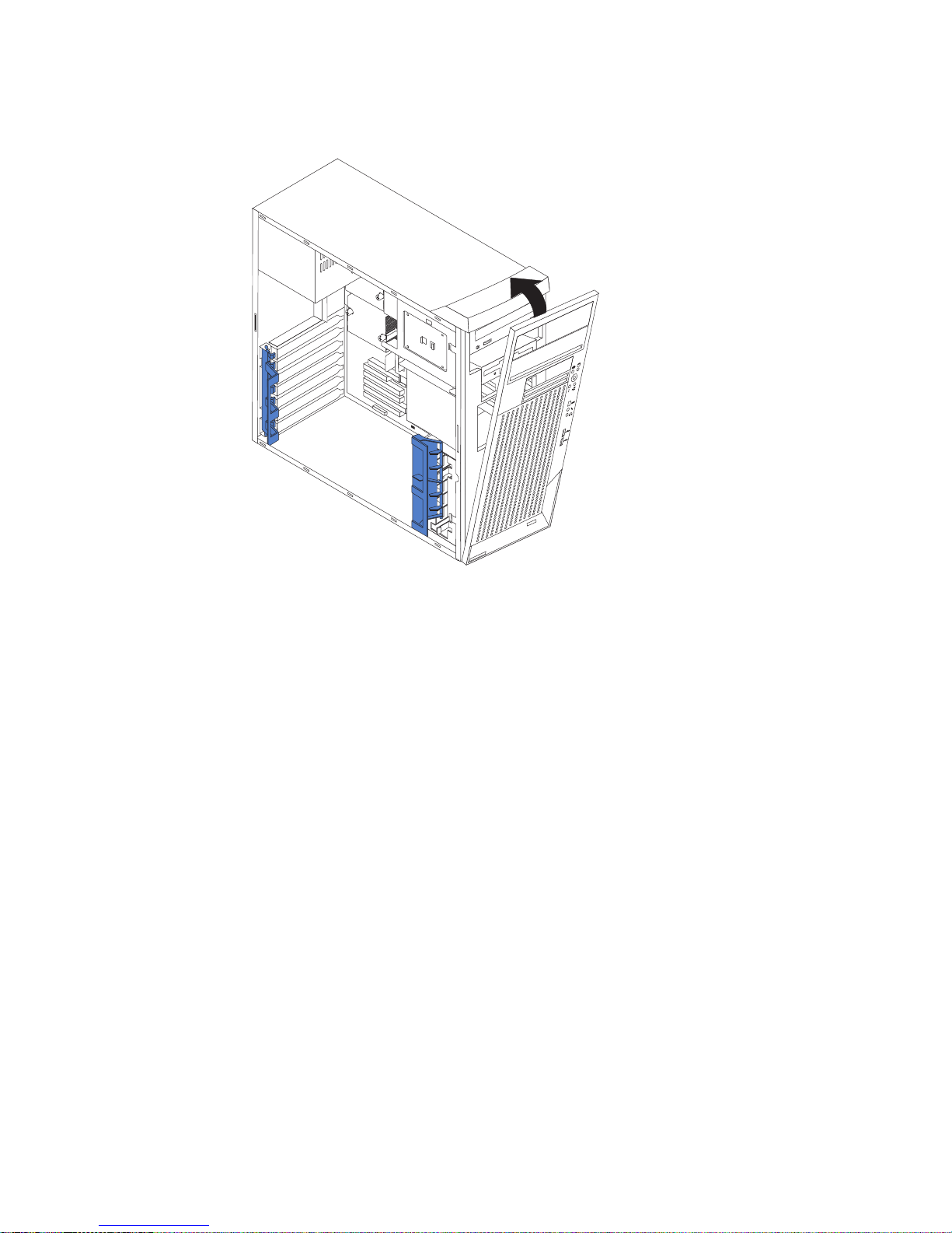
Replacing the bezel
The following illustration shows how to install the bezel on the computer.
4
9
3
1
Complete the following steps to replace the bezel:
1. Insert the two tabs on the bottom of the bezel into the matching holes on the
computer chassis.
2. Push the top of the bezel toward the computer until the two tabs at the top of
the bezel snap into place.
52 IBM IntelliStation Z Pro Type 6221: User’s Guide
Page 75

Replacing the side cover
If you removed the support bracket, reinstall it before you replace the side cover.
See “Removing and installing the support bracket” on page 33.
Note: The rear adapter retaining bracket rests against the computer side cover.
You might find it easier to lay the computer on its side to replace the side
cover.
Complete the following steps to replace the side cover:
1. Before installing the cover, check that all cables, adapters, and other
components are installed and seated correctly and that you have not left loose
tools or parts inside the computer.
2. Place the bottom lip of the side cover over the bottom edge of the computer
chassis.
3. Rotate the side cover to a vertical position, inserting the tabs at the top of the
side cover into the matching slots in the computer chassis.
4. Slide the side cover forward until it locks in place. Press down on the
cover-release-latch button as you close the cover-release latch to lock the side
cover.
4
9
3
1
5. If you have not done so already, make sure that the two front stabilizing feet are
rotated outward so that they properly support the computer. Rotate each foot
outward 90 degrees (see “Moving the stabilizing feet” on page 30).
6. Reconnect the external cables and power cords to the computer; then, connect
the power cords to electrical outlets.
7. Turn on the attached devices; then, turn on the computer.
Chapter 4. Installing options 53
Page 76

Connecting external options
If you install an optional SCSI adapter, or use the secondary channel on the
integrated SCSI controller for external devices, you can attach external SCSI
devices, such as a SCSI storage expansion enclosure, to your computer. To use
secondary channel for external SCSI devices, remove the SCSI knockout from the
rear of the computer and secure the free end of the secondary channel cable in the
new opening.
You can connect a number of optional external devices to the connectors on the
rear and front of the computer.
Complete the following steps to attach an external device:
1. Review the “Installation guidelines” on page 27, the safety precautions listed in
Statement 1 and Statement 5 in the safety information on page vii, and the
documentation that comes with your options.
2. Be sure that your computer and all attached devices are turned off.
3. Follow the instructions that come with the option to prepare it for installation and
to connect it to the computer.
Note: If you are attaching a SCSI device, see “Ultra320 SCSI connector” on
page 58 for SCSI ID and cabling information.
54 IBM IntelliStation Z Pro Type 6221: User’s Guide
Page 77
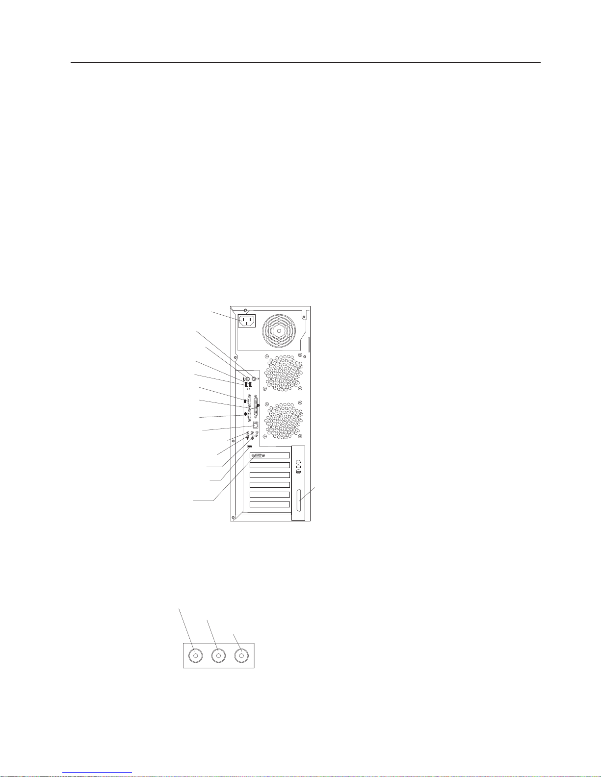
Input/output connectors
Connect optional external devices to the connectors on the front and rear of the
computer.
Your computer has the following input/output (I/O) connectors:
v One audio line in (rear of computer)
v Two audio line out (front and rear of computer)
v Two audio microphone (front and rear of computer)
v One Ethernet (RJ-45)
v Two IEEE 1394 (FireWire) (some models)
v One keyboard
v One mouse
v One parallel
v Two serial
v One Ultra320 SCSI (some models)
v Four universal serial bus (USB) v2.0 ports
v One video
The following illustration shows the locations of these connectors.
Power cord
connector
Mouse
Keyboard
USB 2
USB 1
Serial 1
Parallel
Serial 2
Ethernet
Line out (green)
Line in (blue)
Mic (pink)
IEEE 1394
(FireWire)
Video
2
1
1
2
SCSI knockout
The following sections describe these connectors.
Audio connectors
The audio connectors are used to connect external audio equipment to the
computer.
Line out (green)
Line in (blue)
Mic (pink)
Chapter 4. Installing options 55
Page 78

Microphone
There are two microphone connectors, one on the front and one on the rear of the
computer. Connect a microphone to this connector to record sounds onto the hard
disk or to use speech recognition software.
Line in
There is one line-in connector on the rear of the computer. The computer receives
audio signals through this connector from an external audio device.
Line out
There are two line-out connectors, one on the front and one on the rear of the
computer. The computer sends audio signals through this connector to powered
speakers with built-in amplifiers, headphones, a multimedia keyboard, or the audio
line-in connector on a stereo system. The internal speaker in your computer is
disabled when any device is attached to either the front or rear line-out connector.
Connecting devices to the front line-out connector disables the rear line-out
connector.
Auxiliary-device (pointing-device) connector
There is one auxiliary-device connector on the rear of the computer. Use this
connector to connect a mouse or other pointing device. The following illustration
shows an auxiliary-device connector.
Ethernet (RJ-45) connector
There is one Ethernet connector on the rear of the computer. Use this connector to
connect the computer to a 10-Mbps, 100-Mbps, or 1000-Mbps network. The
following illustration shows an Ethernet connector.
Connect a Category 3, 4, or 5 unshielded twisted-pair (UTP) cable to this connector.
The 100BASE-TX and 1000BASE-T Fast Ethernet standards require Category 5 or
higher cabling.
The Ethernet connector has two LEDs, one that indicates Ethernet-link status and
one that indicates transmit/receive activity. When the Ethernet-link status LED is lit,
it indicates that there is an active connection on the Ethernet port. Activity between
the computer and the network is indicated by the Ethernet transmit/receive activity
LEDs on the front and rear of the computer (see “Controls and indicators” on
page 9).
Activity LED
(green)
6
4
2
8
5
3
1
Link LED
(green)
1
IEEE 1394 (FireWire) connectors
There is one 4-pin IEEE 1394 connector on the front of the computer and one 6-pin
IEEE 1394 connector on the rear of the computer. Use these connectors to connect
IEEE 1394 devices. The following illustrations show the IEEE 1394 connectors.
56 IBM IntelliStation Z Pro Type 6221: User’s Guide
Page 79

4-pin IEEE 1394 (FireWire) connector (front):
6-pin IEEE 1394 (FireWire) connector (rear):
Keyboard connector
There is one keyboard connector on the rear of the computer. Use this connector to
connect a PS/2®(non-USB) keyboard. The following illustration shows a keyboard
connector.
3
4
21
4
2
1
6
3
5
If you attach a keyboard to this connector, USB ports and devices are disabled
during the power-on self-test (POST).
Parallel connector
There is one parallel connector on the rear of the computer. Use this connector to
connect a parallel device. The following illustration shows a parallel connector.
The parallel connector supports three standard Institute of Electrical and Electronics
Engineers (IEEE) 1284 modes of operation: standard parallel port (SPP), enhanced
parallel port (EPP), and extended capability port (ECP). If you configure the parallel
port to operate in bidirectional mode, it supports the ECP and EPP modes. When
the parallel connector is configured as bidirectional, use an IEEE 1284-compliant
cable that does not exceed 3 meters (9.8 ft). Use the Configuration/Setup Utility
program to configure the parallel connector as bidirectional.
Complete the following steps to view or configure the parallel connector:
1. Restart the computer.
2. Press and hold the F1 key to launch the Configuration/Setup Utility program.
3. On the Configuration/Setup Utility menu, use the cursor keys on the keyboard to
4. Follow the instructions on the screen to save your changes and exit from the
13
25
select Devices → Parallel Port.
Configuration/Setup Utility menu.
6
4
2
5
3
1
1
14
Chapter 4. Installing options 57
Page 80

Serial connectors
There are two serial connectors on the rear of the computer. Use these connectors
to connect serial devices. The following illustration shows a serial connector.
Ultra320 SCSI connector
An optional external SCSI connector might be installed on the rear of the computer.
Use this connector to connect external SCSI devices. The following illustration
shows the SCSI standard 68-pin, female D-shell SCSI connector.
Your computer has an integrated SCSI controller with RAID capabilities. This
dual-channel controller supports two independent, Ultra320 SCSI channels. The
SCSI connectors for both channels are on the system board. Each channel
supports up to 15 SCSI devices. This controller uses:
v Double-transition clocking to achieve up to 320 MB-per-second data-transfer
rates
v Domain name validation to negotiate compatible data-transfer speeds with each
device
v Cyclic-redundancy checking (CRC), instead of the usual parity checking, to
improve data reliability
v An active terminator for SCSI bus termination
34
68
1
69
5
1
35
SCSI cabling requirements
You can install three internal SCSI devices using the SCSI signal cable that comes
with some computer models. If you plan to attach external SCSI devices, you must
order an additional SCSI cable, remove the SCSI knockout from the rear of the
computer, and connect the new cable from the system board to this opening. To
select and order the correct cables for use with external devices, contact your IBM
reseller or IBM marketing representative. When using an optional SCSI adapter, you
must also connect the SCSI adapter to the SCSI LED (J18) connector on the
system board receive an indication of SCSI hard-disk drive activity. See
“System-board internal connectors” on page 29 for the location of the SCSI
connectors.
Setting SCSI IDs
Each SCSI device connected to a SCSI controller must have a unique SCSI ID.
This ID enables the SCSI controller to identify the device and ensure that different
devices on the same SCSI channel do not attempt to transfer data simultaneously.
SCSI devices that are connected to different SCSI channels can have duplicate
SCSI IDs. See the information that is provided with the device for instructions about
setting its SCSI ID.
Universal Serial Bus connectors
There are four Universal Serial Bus (USB) v2.0 connectors, two on the front of the
computer and two on the rear of the computer. Use the USB connectors to connect
58 IBM IntelliStation Z Pro Type 6221: User’s Guide
Page 81

optional telephony and multimedia devices. USB 2.0 technology transfers data at up
to 480 megabits per second (Mbps) with a maximum of 127 external devices and a
maximum signal distance of 5 meters (16 ft) per segment (if the device that is
attached to the computer is a USB 2.0 device). If the computer has multiple USB
devices attached to it, the USB hub must be USB 2.0, otherwise, all USB 2.0
devices will transfer data at 12 Mbps. Using Plug and Play technology, USB devices
are configured automatically. The following illustration shows a USB connector.
Use a 4-pin USB cable to connect external devices to USB connectors.
If you connect a PS/2 (non-USB) keyboard to the keyboard connector, USB ports
and devices are disabled during power-on self-test (POST).
If you connect a USB keyboard that has a mouse port, the keyboard emulates a
mouse, and you cannot disable the mouse settings in the Configuration/Setup Utility
program.
Video connector
The Accelerated Graphics Port (AGP) adapter, which is in the AGP slot on the
system board, provides the video connector. This connector is on the rear of the
computer. Use the video connector to connect a monitor or other display. The
following illustrations show the different types of video connector that can come with
your computer.
14
Analog video connector:
This connector is on the Matrox DVI-I to dual VGA pigtail cable and on the NVIDIA
LFH-60 to dual VGA pigtail cable.
5
1
1115
Digital (DVI-I) video connector:
This connector is on the Matrox Millennium G450, NVIDIA Quadro4 980XGL, and
3Dlabs Wildcat4 7110 video adapters.
1
C1 C2
C3C5C4
Low force helical-60 (LFH-60) video connector:
This connector is on the NVIDIA Quadro4 280NVS video adapter.
Some models come with a digital video interface (DVI) connector for connecting a
digital monitor. If you have problems viewing information with a second monitor, see
“Changing monitor settings” on page 15.
Chapter 4. Installing options 59
Page 82

Models with the Matrox Millennium G450 DVI-I video adapter come with a DVI-I to
dual-analog monitor pigtail cable.
Models with the Wildcat4 7110 or NVIDIA Quadro4 980XGL video adapter come
with a DVI-I to VGA style analog converter for each DVI-I connector.
Attention: On the Wildcat4 7110 video adapter, the first or only monitor must be
connected to the bottom connector (connector number 1).
Models with the NVIDIA Quadro4 280NVS video adapter come with a low force
helical-60 (LFH-60) to dual-analog monitor pigtail cable. If you want to setup two
digital monitors, you will need to purchase a separate dual-digital monitor cable.
60 IBM IntelliStation Z Pro Type 6221: User’s Guide
Page 83

Chapter 5. Solving problems
This section provides basic troubleshooting information to help you identify and
resolve some problems that might occur.
If you cannot locate and correct the problem using the information in this chapter,
see Appendix A, “Getting help and technical assistance” on page 93 for more
information.
Diagnostic tools overview
The following tools are available to help you identify and resolve hardware-related
problems:
v Computer Support flowchart
The Computer Support flowchart on the following page will help you determine
how to access help from IBM and register your computer.
v POST beep codes and error messages
The power-on self-test generates beep codes and messages to indicate
successful test completion or the detection of a problem. See “Power-on self-test
(POST)” on page 63 for more information.
v Diagnostic programs
The system diagnostic programs are stored on the Device Drivers and IBM
Enhanced Diagnostics CD. These programs are the primary methods of testing
the major components of your computer. See “Diagnostic programs and error
messages” on page 72 for more information.
v Troubleshooting charts
These charts list problem symptoms and steps to correct each problem. See the
“Troubleshooting charts” on page 78 for more information.
v System-board error LEDs
An LED on the system board might be lit to help isolate an error indicated by the
system error LED on the front of the computer. See the “System-board error
LEDs” on page 85 for more information.
© Copyright IBM Corp. 2002 61
Page 84

Computer Support
Computer working
properly?
Ye s
No
Check all cables for loose connections
and verify that all optional devices you
installed are on the compatibility matrix.
You can view the atcompatibility matrix
http://www.pc.ibm.com/us/compat/
intellistation/
Problem
solved?
Ye s
No
Use the troubleshooting
information provided with
your computer to determine
the cause of the problem
and the action to take.
Register and profile your computer
After you register and profile, you will be able to:
• Diagnose problems using the IBM Online Assistant
• Participate in the IBM discussion forum
• Receive e-mail notifications of technical updates
related to your profiled products
Register:
Profile at
http://www.ibm.com/pc/register/
http://www.ibm.com/pc/support/
View information about IBM Support
Line at
http://www.ibm.com/services/sl/products/
or view support telephone numbers at
http://www.ibm.com/planetwide/
View support telephone numbers at
http://www.ibm.com/planetwide/
Problem
solved?
Ye s
No
Flash the latest levels of BIOS,
and download the latest level of
diagnostics. You can download
this code at
http://www.ibm.com/pc/support/
62 IBM IntelliStation Z Pro Type 6221: User’s Guide
Ye s
Problem
solved?
No
Hardware
Software
Hardware
or Software
problem?
Page 85

Power-on self-test (POST)
When you turn on the computer, the power-on self-test (POST) performs a series of
tests to check the operation of system components and some of the installed
options.
If POST finishes without detecting any problems, the first window of your operating
system or application program appears.
If POST detects a problem, more than one beep might sound, an error message
might appear on your screen, or both.
Notes:
1. If you have a user password set, you must type the password and press Enter,
when prompted, before the operating system will load.
2. A single problem might cause several error messages. When this occurs, work
to correct the cause of the first error message. After you correct the cause of
the first error message, the other error messages typically will resolve the next
time you run the test.
POST beep codes
The possible types of beep codes are:
No beeps
No beep codes indicates that your computer successfully completed POST
without finding any errors.
Continuous beep
Your startup (boot) microprocessor has failed, or your system board or
speaker subsystem might contain a failing component. If the system
continues through POST with no errors, call for service. If no video appears,
the startup processor has failed.
Beep codes for specific failures
Beep codes indicating specific system problems are listed in the following
table.
Table 3. POST beep codes
Beep code Description Action
1-1-2 Microprocessor register test has failed. Call for service
1-1-3 CMOS write/read test has failed.
1-1-4 BIOS EEPROM checksum has failed.
1-2-1 Programmable Interval Timer test has failed.
1-2-2 DMA initialization has failed.
1-2-3 DMA page register write/read test has failed.
1-2-4 RAM refresh verification has failed. Reseat the
memory modules
1-3-1 First 64 Kb RAM test has failed.
1-3-2 First 64 Kb RAM parity test has failed.
or install a
memory module. If
the problem
remains, call for
service.
Chapter 5. Solving problems 63
Page 86

Table 3. POST beep codes (continued)
Beep code Description Action
2-1-1 Secondary DMA register test has failed. Call for service
2-1-2 Primary DMA register test has failed.
2-1-3 Primary interrupt mask register test has failed.
2-1-4 Secondary interrupt mask register test has failed.
2-2-2 Keyboard controller test has failed.
2-2-3 CMOS power failure and checksum checks have failed.
2-2-4 CMOS configuration information validation has failed.
2-3-2 Screen memory test has failed. Call for service
2-3-3 Screen retrace tests have failed.
2-3-4 Search for video ROM has failed.
2-4-1 Screen test indicates the screen is operable.
3-1-1 Timer tick interrupt test has failed.
3-1-2 Interval timer channel 2 test has failed.
3-1-3 RAM test has failed above address 0FFFFH.
3-1-4 Time-of-Day clock test has failed.
3-2-1 Serial port test has failed.
3-2-2 Parallel port test has failed.
3-2-4 Comparison of CMOS memory size against actual has
failed.
3-3-1 A memory size mismatch has occurred. Reseat the
memory modules
or install a
memory module. If
the problem
remains, call for
service.
3-3-2 Critical SMBUS error occurred (I2C bus has failed). Call for service
3-3-3 No optional memory in the system.
Attention: In some memory configurations, the 3-3-3
beep code might sound during POST followed by a
blank display screen. If this occurs and the Boot Fail
Count feature in the Start Options of the
Configuration/Setup Utility program is set to Enabled
(its default setting), you must restart the computer three
times to force the system BIOS to reset the memory
connector from Disabled to Enabled.
Reseat the
memory modules
or install a
memory module. If
the problem
remains, call for
service.
64 IBM IntelliStation Z Pro Type 6221: User’s Guide
Page 87

POST error messages
The following table provides information about the POST error messages that can
appear during startup.
Table 4. POST error messages
POST message Description
062 The computer failed to boot on three consecutive attempts.
All caches are disabled. Repeatedly turning the computer on and then off or resetting the
computer might cause this problem.
Action: Take the following steps to correct the problem:
1. Start the Configuration/Setup Utility program and verify that all settings are correct. Use the
Cache Control selection in the Advanced Setup menu of the Configuration/Setup Utility
program to enable the caches.
2. Install a new battery. See “Replacing the battery” on page 90 for instructions.
If the problem remains, call for service. When the problem is corrected, be sure to enable the
caches.
101, 102, and 106 An error occurred during the system board and microprocessor test.
Action: Call for service.
114 An adapter read-only memory (ROM) error occurred.
Action: Remove the options. If you can start the computer without the options installed,
reinstall each option one at a time and retest after each is reinstalled. When an option fails,
replace it.
If you cannot isolate and correct the problem, call for service.
129 An error was detected in the L1 cache of one of the microprocessors.
Action: Take the following steps to correct the problem:
1. If you just installed a microprocessor, verify that the microprocessor is installed and seated
correctly.
2. If the problem remains, call for service.
151 A real-time clock (RTC) error or CMOS checksum error occurred.
Action: Take the following steps to correct the problem:
1. Restart the computer.
2. If the problem remains, call for service.
161 The real-time clock battery has failed.
Action: Replace the battery yourself or call for service.
You can use the computer until you replace the battery. However, you must run the
Configuration/Setup Utility program and set the time and date and other custom settings each
time you turn on the computer.
Chapter 5. Solving problems 65
Page 88

Table 4. POST error messages (continued)
POST message Description
162 A change in device configuration occurred. This error occurs under one or more of the
following conditions:
v A new device has been installed.
v A device has been moved to a different location or cable connection.
v A device has been removed or disconnected from a cable.
v A device is failing and is no longer recognized by the computer as being installed.
v An external device is not turned on.
v An invalid checksum is detected in the battery-backed memory.
Action: Verify that all external devices are turned on. You must turn on external devices
before turning on the computer.
If you did not add, remove, or change the location of a device, a device is probably failing.
Running the Diagnostic program might isolate the failing device. See “Creating an IBM
Enhanced Diagnostics diskette” on page 14 and “Using an IBM Enhanced Diagnostics diskette”
on page 87.
If the problem remains, call for service.
163 The time of day has not been set.
Action: Set the correct date and time. If the date and time are set correctly and saved, but
the 163 error message reappears, call for service.
You can use the computer until the system is serviced, but any application programs that use
the date and time will be affected.
164 A change in the memory configuration occurred. This message might appear after you add or
remove memory.
Note: The computer can be used with decreased memory capacity.
Action: Take the following steps to correct the problem:
1. If POST error message 289 also occurred, follow the instructions for that error message
first.
2. If you just installed or removed memory, run the Configuration/Setup Utility program; then,
exit, saving the new configuration settings.
If the message appears again, shut down the computer, reseat the memory modules, and
restart the computer.
If the problem remains, call for service.
175 A vital product data (VPD) error occurred.
Action: Call for service.
176, 177, and 178 A security hardware error occurred.
Action: Check for indications that someone has tampered with the computer. If no one has
tampered with the computer, call for service.
184 The power-on password information stored in your computer has been removed.
Action: From the Configuration/Setup Utility program main menu, select System Security.
Then, follow the instructions on the screen.
If this information cannot be restored, call for service.
185 A power failure damaged the stored information about the drive-startup sequence.
Action: From the Configuration/Setup Utility program main menu, select Start Options; then,
follow the instructions on the screen.
If this information cannot be restored, call for service.
186 A system board or hardware error occurred.
Action: Call for service.
66 IBM IntelliStation Z Pro Type 6221: User’s Guide
Page 89

Table 4. POST error messages (continued)
POST message Description
187 The VPD serial number is not set.
Action: When a supported Remote Supervisor Adapter (RSA) is installed, the system serial
number is set in the VPD EEPROM each time the computer is restarted. If the system board
has been replaced, the system serial number will be invalid and should be set. To view the
system serial number, select System Information from the main menu of the
Configuration/Setup Utility program and then select Product Data. If the problem remains, call
for service.
188 A vital product data (VPD) error occurred.
Action: Call for service.
189 An attempt has been made to access the computer with invalid passwords. After three
incorrect attempts, the computer locks up; that is, the logon data fields are no longer available
to the user.
201 An error occurred during the memory controller test. This error can be caused by:
v Incorrectly installed memory
v A failing memory module
v A system board problem
Action: Take the following steps to correct the problem:
1. If you just installed memory, verify that the new memory is correct for your computer. Also
verify that the memory is installed and seated correctly.
2. If the problem remains, call for service.
229 An error was detected in the L2 cache of one of the microprocessors.
Action: Take the following steps to correct the problem:
1. If you just installed a microprocessor, verify that the microprocessor is installed and seated
correctly.
2. If the problem remains, call for service.
289 An error occurred during POST memory tests and a failing DIMM was disabled.
Note: You can use the computer with decreased memory.
Action: Take the following steps to correct the problem:
1. If you just installed memory, verify that the new memory is correct for your computer. Also
verify that the memory is installed and seated correctly. Start the Configuration/Setup Utility
program and select Memory Settings from the Advanced Setup menu to enable the
DIMM.
2. If the problem remains, replace the failing DIMM.
If the problem remains, call for service.
301 and 303 An error occurred during the keyboard and keyboard controller test. These error messages
also might be accompanied by continuous beeping.
Action: Take the following steps to correct the problem:
1. Ensure that:
v Nothing is resting on the keyboard and pressing a key.
v No key is stuck.
v The keyboard cable is connected correctly to the keyboard and to the correct connector
on the computer.
2. After installing a USB keyboard, you might need to use the Configuration/Setup Utility
program to enable keyboardless operation and prevent the POST error message from
being displayed during startup.
Running the diagnostic tests can isolate the computer component that failed, but you must
have your system serviced. If the error message remains, call for service.
Note: If you just connected a new mouse or other pointing device, turn off the computer and
disconnect that device. Wait at least 5 seconds; then, turn on the computer. If the error
message goes away, replace the device.
Chapter 5. Solving problems 67
Page 90

Table 4. POST error messages (continued)
POST message Description
602 Invalid diskette boot record
Action: Take the following steps to correct the problem:
1. Replace the diskette.
2. If the problem remains, make sure that the diskette drive cables are correctly and securely
connected.
3. If the problem remains, replace the diskette drive.
If the problem remains, call for service.
604 An error occurred during a diskette drive test.
Action: Take the following steps to correct the problem:
1. Verify that the Configuration/Setup Utility program correctly reflects the type of diskette
drive that you have installed.
2. Run the diagnostic tests. If the diagnostic tests fail, call for service.
662 A diskette drive configuration error occurred.
Action: If you removed a diskette drive, make sure that the diskette drive setting is correct in
the Configuration/Setup Utility program. If the setting is not correct, change it.
If the problem remains, call for service.
962 A parallel port configuration error occurred.
Action: If you changed a hardware option, make sure that the parallel port setting is correct in
the Configuration/Setup Utility program. If the setting is not correct, change it.
If the problem remains, call for service.
11xx An error occurred during the system-board serial port test.
Action: If you have a serial device attached to your computer, verify that the serial cable is
connected correctly. If it is, use the following procedure:
1. Turn off the computer.
2. Disconnect the serial cable from the serial port.
3. Wait five seconds; then, turn on the computer.
If the POST error message does not reappear, either the serial cable or the device is probably
failing. See the documentation that comes with the serial device for additional testing
information.
If the POST error message reappears, call for service.
1162 The serial port configuration conflicts with another device in the system.
Action: Take the following steps to correct the problem:
1. Make sure the IRQ and I/O port assignments needed by the serial port are available.
2. If all interrupts are being used by adapters, you might need to remove an adapter to make
an interrupt available to the serial port, or force other adapters to share an interrupt.
1600 The Advanced System Management processor is not functioning.
Action: Take the following steps to correct the problem:
1. Verify that the jumpers for the system-management processor are set correctly.
2. Disconnect the computer from all electrical sources, wait for 30 seconds, reconnect the
computer to the electrical sources, and restart the computer.
If the problem remains, call for service.
1601 An Advanced System Management Flash update is needed.
Action: Download and install the latest Advanced System Management flash update.
68 IBM IntelliStation Z Pro Type 6221: User’s Guide
Page 91

Table 4. POST error messages (continued)
POST message Description
1762 Hard disk configuration error.
Action: Take the following steps to correct the problem:
1. Make sure that the hard disk drive is set correctly in the Configuration/Setup Utility
program.
2. Make sure that the hard disk drive cables are correctly and securely connected.
3. If the problem remains, replace the hard disk drive.
If the problem remains, call for service.
1800 A PCI adapter has requested a hardware interrupt that is not available.
Action: Take the following steps to correct the problem:
1. Make sure that the PCI adapter and all other adapters are set correctly in the
Configuration/Setup Utility program. If the interrupt resource settings are not correct,
change the settings.
2. If all interrupts are being used by other adapters, you might need to remove an adapter to
make an interrupt available to the PCI adapter, or force other adapters to share an
interrupt.
1962 No valid startup devices were found. The system cannot find the startup drive or operating
system.
Action: Be sure that the drive you want to start from is in the startup sequence.
1. Select Start Options from the Configuration/Setup Utility program main menu. If you are
unable to set the startup sequence, call for service.
2. Check the list of startup devices in the Startup device data fields. Is the drive you want to
start from in the startup sequence?
Yes Exit from this screen; then, select Exit Setup to exit the Configuration/Setup
menu. Go to step 3.
No Follow the instructions on the screen to add the drive; then, save the changes and
exit the Configuration/Setup menu. Restart the computer.
3. Is an operating system installed?
Yes Turn off the computer. Go to step 4.
No Install the operating system in your computer; then, follow your operating system
instructions to shut down and restart the computer.
4. During computer startup, watch for messages indicating a hardware problem.
If the same error message appears, call for service.
2400 An error occurred during the testing of the video controller on the system board. This error can
be caused by a failing system board or a failing video adapter (if one is installed).
Action: Call for service.
2462 A video memory configuration error occurred.
Action: Call for service.
5962 An IDE CD-ROM configuration error occurred.
Action: Check the signal and power cable connections to the CD-ROM drive.
If the problem remains, call for service.
Chapter 5. Solving problems 69
Page 92

Table 4. POST error messages (continued)
POST message Description
8603 An error occurred during the mouse (pointing device) controller test. The addition or removal of
a mouse, or a failing system board can cause this error.
Note: This error also can occur if electrical power was lost for a very brief period and then
restored. In this case, turn off the computer for at least 5 seconds; then, turn it back on.
Action: Ensure that the keyboard and mouse (pointing device) are attached to the correct
connectors. If they are connected correctly, use the following procedure:
1. Turn off the computer.
2. Disconnect the mouse from the computer.
3. Turn on the computer.
If the POST error message does not reappear, the mouse is probably failing. See the
documentation that comes with the mouse for additional testing information. If the problem
remains, replace the mouse or pointing device.
If the POST error message reappears, run the diagnostic tests to isolate the problem. If the
diagnostic tests do not find a problem and the POST error message remains, call for service.
00012000 Processor machine check.
Action: Take the following steps to correct the problem:
1. Update the system BIOS.
2. If the problem remains, replace the microprocessor.
00019501 Microprocessor 1 is not functioning.
Action: Replace microprocessor 1.
If the problem remains, call for service.
00019502 Microprocessor 2 is not functioning.
Action: Replace microprocessor 2.
If the problem remains, call for service.
00019701 The microprocessor failed the built-in self test.
Action: Replace the microprocessor.
If the problem remains, call for service.
00180100 A PCI adapter has requested memory resources that are not available
Action: Take the following steps to correct the problem:
1. Make sure that the PCI adapter and all other adapters are set correctly in the
Configuration/Setup Utility program. If the memory resource settings are not correct,
change the settings.
2. If all memory resources are being used, you might need to remove an adapter to make
memory available to the PCI adapter. Disabling the adapter BIOS on the adapter might
correct the error. See the documentation provided with the adapter.
00180200 A PCI adapter has requested an I/O address that is not available, or the PCI adapter might be
defective.
Action: Take the following steps to correct the problem:
1. Make sure that the I/O address for the PCI adapter and all other adapters are set correctly
in the Configuration/Setup Utility program.
2. If the I/O port resource settings are correct, the PCI adapter might be defective. Call for
service.
00180300 A PCI adapter has requested a memory address that is not available, or the PCI adapter might
be defective.
Action: Take the following steps to correct the problem:
1. Make sure that the memory address for all other adapters are set correctly in the
Configuration/Setup Utility program. If the memory resource settings are not correct,
change the settings.
2. If the memory resource settings are correct, the PCI adapter might be defective. Call for
service.
70 IBM IntelliStation Z Pro Type 6221: User’s Guide
Page 93

Table 4. POST error messages (continued)
POST message Description
00180400 A PCI adapter has requested a memory address that is not available.
Action: If all memory addresses are being used, you might need to remove an adapter to
make memory address space available to the PCI adapter. Disabling the adapter BIOS on the
adapter might correct the error. See the documentation provided with the adapter.
00180500 A PCI adapter ROM error occurred.
Action: Remove the PCI adapters. If you can start the computer without the adapters,
reinstall each adapter one at a time and retest after each is reinstalled. When an adapter fails,
replace it.
If you cannot isolate and correct the problem, call for service.
00180600 A PCI-to-PCI bridge error occurred. More than one PCI bus tried to access memory below
1MB.
Action: Remove the PCI adapter that has the PCI bridge. If you can start the computer
without the adapter, reinstall and retest the adapter. If the adapter fails, replace it.
If you cannot isolate and correct the problem, call for service.
00180700 xxxxyyyy Planar PCI device does not respond or disabled by user. (Where xxxx is the PCI
vendor ID and yyyy is the PCI device ID.)
Action: Start the Configuration/Setup Utility program, select Devices and I/O Ports, and make
sure that the device is enabled. If the problem remains, call for service.
00180800 An unsupported PCI device is installed.
Action: Remove the PCI adapters. If you can start the computer without the adapters,
reinstall each adapter one at a time and retest after each is reinstalled. When an adapter fails,
replace it.
If the problem remains, call for service.
00181000 PCI error.
Action: Remove the PCI adapters. If you can start the computer without the adapters,
reinstall each adapter one at a time and retest after each is reinstalled. When an adapter fails,
replace it.
If the problem remains, call for service.
01295085 The ECC checking hardware test failed.
Action: Call for service.
01298001 No update data is available for the processor.
Action: Update the system BIOS to a level that supports the microprocessors installed in the
computer.
01298101 The update data for the microprocessor is incorrect.
Action: Update the system BIOS to a level that supports the microprocessors installed in the
computer.
01298200 Microprocessor speed mismatch
Action: The microprocessors installed do not run at the same speed; install microprocessors
with identical speeds.
I9990301 A hard disk drive error occurred.
Action: Call for service.
I9990305 POST could not find an operating system.
Action: Install an operating system. If you have already installed the operating system, check
the drive startup sequence. If the drive sequence is correct, run the diagnostic tests to verify
that the hard disk drive is functioning correctly. If there is a problem with the hard disk drive
(such as a bad sector), you might need to reinstall the operating system.
If you cannot reinstall the operating system, call for service.
Chapter 5. Solving problems 71
Page 94

Table 4. POST error messages (continued)
POST message Description
I9990650 AC power has been restored.
Action: No action is required. This message appears each time AC power is restored to the
computer after an AC power loss.
Other Numbers POST found an error.
Action: Follow the instructions on the screen.
Diagnostic programs and error messages
The system diagnostic programs are stored on the Device Drivers and IBM
Enhanced Diagnostics CD that comes with your computer. These programs are the
primary method of testing the major components of your computer and assist in
isolating problems in the computer hardware and software. The diagnostic programs
run independently of the operating system and must be run from either a CD or
diskette.
This diskette, known as an IBM Enhanced Diagnostics diskette, can be created
using Access IBM. You can also download the latest version of the diagnostics
programs from http://www.ibm.com/pc/support on the World Wide Web and use the
downloaded file to create an IBM Enhanced Diagnostics diskette. See “Using an
IBM Enhanced Diagnostics diskette” on page 87 for instructions.
Note: When using diagnostics with a USB keyboard and mouse attached, first go
into the Configuration/Setup Utility and enable USB emulation.
1. Restart the computer and press F1 to access the Configuration/Setup
Utility.
2. Select Devices and I/O Ports.
3. Select USB Setup.
4. Make sure USB Keyboard and Mouse are enabled.
Diagnostic error messages indicate that a problem exists; they are not intended to
be used to identify a failing part. Troubleshooting and servicing complex problems
that are indicated by error messages should be performed by trained service
personnel.
Sometimes the first error to occur causes additional errors. In this case, the
computer displays more than one error message. Always follow the suggested
action instructions for the first error message that appears.
The following sections contain the error codes that might be displayed in the
detailed test log and summary log, when running the diagnostic programs.
The error code format is as follows:
fff-ttt-iii-date-cc-text message
where:
fff is the three-digit function code that indicates the function being tested when
the error occurred. For example, function code 201 is for memory.
72 IBM IntelliStation Z Pro Type 6221: User’s Guide
Page 95

Text messages
ttt is the three-digit failure code for the exact test failure. (These codes are for
trained service personnel and are described in the Hardware Maintenance
Manual.)
iii is the three-digit device ID. (These codes are for trained service personnel
and are described in the Hardware Maintenance Manual.)
date is the date that the diagnostic test was run and the error recorded.
cc are the check digits that are used to verify the validity of the information.
text message
is the diagnostic message that indicates the reason for the problem.
The diagnostic text message format is as follows:
Function Name: Result (test specific string)
where:
Function Name
is the name of the function being tested when the error occurred. This
corresponds to the function code (fff) given in the previous list.
Result
can be one of the following:
Passed
This result occurs when the diagnostic test is completed without
any errors.
Failed This result occurs when the diagnostic test discovers an error.
User Aborted
This result occurs when you stop the diagnostic test before it is
complete.
Not Applicable
This result occurs when you specify a diagnostic test for a device
that is not present.
Aborted
This result occurs when the test could not proceed because of the
system configuration.
Warning
This result occurs when a possible problem is reported during the
diagnostic test, such as when a device that is to be tested is not
installed.
Test Specific String
is additional information that is used to analyze the problem.
Starting the diagnostic programs and viewing the test log
The test log records data about system failures and other pertinent information. The
test log will not contain any information until after the diagnostic program has run.
Note: If you already are running the diagnostic program, begin with step 4.
Chapter 5. Solving problems 73
Page 96

Complete the following steps to view the test log:
1. Insert the IBM Enhanced Diagnostics diskette or the Device Drivers and IBM
Enhanced Diagnostics CD.
2. Shut down your operating system and restart the computer.
3. If a user password is set, the system prompts you for it. Type the password,
and press Enter.
4. Run the appropriate diagnostics program and when the Diagnostic Programs
screen appears, select Utility.
5. Select View Test Log from the list that appears; then, follow the instructions on
the screen.
6. Save the test log to a file on a diskette or to your hard disk.
Notes:
a. To save the test log to a diskette, you must use a diskette that you have
formatted yourself; this function does not work with preformatted diskettes. If
the diskette has sufficient space for the test log, the diskette may contain
other data.
b. The system maintains the test-log data while the system is turned on. When
you turn off the power to the computer, the test log is cleared.
Diagnostic error message tables
The following tables provide descriptions of the error messages that might be listed
in the test log after you run the diagnostic programs.
Important: If error messages are displayed that are not listed in the following table,
make sure that your computer has the latest level of BIOS code installed.
Code Function Result Text message Action
001 Core system Failed System board, ECC Test Call for service.
System board
005 Video port Failed System board
011 Serial port Failed Integrated serial port
014 Parallel port Integrated parallel port
015 USB interface Aborted Can NOT test USB interface while it is in use.
Note: If you have a USB keyboard or mouse
attached, you cannot run the diagnostic program
for the USB interface.
Failed System board Call for service.
1. Replace video
adapter (if installed).
2. If the problem
remains, call for
service.
1. Make sure loopback
plug is installed and
rerun test.
2. If the problem
remains, call for
service.
1. Turn off the
computer.
2. Replace the USB
keyboard and mouse
with a standard
keyboard and mouse.
3. Turn on the
computer.
4. Run the diagnostic
test again.
74 IBM IntelliStation Z Pro Type 6221: User’s Guide
Page 97

Code Function Result Text message Action
020 PCI interface Failed System board Call for service.
030 SCSI interface Failed SCSI adapter in slot n failed register/counter/
power test
See the information
provided with the adapter
for instructions.
(where n is the slot number of the failing adapter)
If the problem remains,
call for service.
035 RAID adapter Failed RAID adapter is not configured properly 1. Check RAID adapter
cable.
2. Replace RAID
adapter.
3. Replace SCSI hard
disk drive.
4. If the problem
remains, call for
service.
089 Microprocessor Failed Any failure message 1. Verify the
microprocessor is
installed and seated
correctly.
2. If your machine does
not have the latest
level of BIOS
installed, update the
BIOS.
3. If the problem
remains, call for
service.
180 Status display Failed Any failure message Call for service.
201 System memory Failed DIMM is in location DIMM n
1. Reseat the failing
DIMM.
(where n is the number of the socket that
contains the failing DIMM)
2. If the problem
remains, replace the
DIMM.
3. If the problem
remains, call for
service.
Test setup error: Corrupt BIOS in ROM If your computer does
not have the latest level
BIOS installed, update
Test setup error: Corrupt DMI BIOS, information
in BIOS is not as expected
the BIOS to the latest
level.
If the problem remains,
call for service.
Chapter 5. Solving problems 75
Page 98

Code Function Result Text message Action
202 Microprocessor Failed Any failure message 1. Verify the
microprocessor is
installed and seated
correctly.
2. If your machine does
not have the latest
level of BIOS
installed, update the
BIOS.
3. If the problem
remains, call for
service.
206 Diskette drive Failed Internal diskette drive bay 1. Rerun the diagnostic
with a different
diskette.
2. If the problem
remains, call for
service.
215 CD-ROM Failed On system board. 1. Rerun the diagnostic
with a different
CD-ROM.
2. Verify that the cables
are properly
Aborted The CD-ROM drive is not present.
217 Hard disk drive Failed BIOS drive # n (where n is the drive bay number) 1. Verify that the cables
301 Keyboard Failed On system-board keyboard test failed 1. Verify that the
connected to the
CD-ROM drive.
3. If the problem
remains, call for
service.
are properly
connected to the hard
disk drive and that
these cables are
properly terminated.
2. If the problem
remains, call for
service.
keyboard cable is
connected to the
correct port (not the
mouse port).
2. Replace the keyboard
cable.
3. Replace the
keyboard.
4. If the problem
remains, call for
service.
76 IBM IntelliStation Z Pro Type 6221: User’s Guide
Page 99

Code Function Result Text message Action
302 Mouse Failed On system-board pointing device test failed. 1. Verify that the
pointing device cable
is connected to the
correct port (not the
keyboard port).
2. Replace the pointing
device.
3. If the problem
remains, call for
service.
305 Video monitor Any message See the information that
came with the monitor.
405 Ethernet Failed In PCI slot n
(where n is the PCI slot number in which the
failing Ethernet adapter is installed)
On system board 1. Verify that Ethernet is
415 Modem Failed Any failure message 1. Check modem cable.
1. Verify that Ethernet is
enabled in BIOS.
2. Replace the Ethernet
adapter in slot n.
3. If the problem
remains, call for
service.
enabled in BIOS.
2. If the problem
remains, call for
service.
2. Replace modem.
3. If the problem
remains, call for
service.
Small computer system interface (SCSI) messages
If you receive a SCSI error message when running the SCSISelect Utility program,
one or more of the following might be causing the problem:
v A failing SCSI device (adapter or drive)
v An improper SCSI configuration
v Duplicate SCSI IDs in the same SCSI chain
v An improperly installed SCSI terminator
v A defective SCSI terminator
v An improperly installed cable
v A defective cable
To solve the problem, verify that:
v The external SCSI devices are turned on. External SCSI devices must be turned
on before the computer.
v The cables for all external SCSI devices are connected correctly.
v The last device in each SCSI chain is terminated properly.
v The SCSI devices are configured correctly.
Chapter 5. Solving problems 77
Page 100

If you have verified these items and the problem persists, run the diagnostic
programs to obtain additional information about the failing device. If the error
remains or recurs, call for service.
Note: If your system does not have a SCSI hard disk drive, ignore any message
that indicates that the BIOS code is not installed.
PC-Doctor for Windows
Your computer contains PC-Doctor for Windows, which is designed specifically for
the Windows operating environment. Because these diagnostics work with the
operating system, they test hardware and analyze certain software components.
These diagnostic programs are especially useful for isolating operating-system and
device-driver problems.
Complete the following steps to use PC-Doctor for Windows:
1. On the Windows desktop, click start → All Programs → PC-Doctor →
PC-Doctor.
2. Follow the instructions on the screen. Help is available online.
Troubleshooting charts
You can use the troubleshooting charts in this section to find solutions to problems
that have definite symptoms.
Important: If diagnostic error messages are displayed that are not listed in the
following tables, make sure that your system has the latest levels of BIOS code
installed.
See “Starting the diagnostic programs and viewing the test log” on page 73 to test
the computer. If you have run the diagnostic test programs or if running the tests
does not detect the problem, call for service.
Look for the symptom in the left column of the chart. Instructions and probable
solutions to the problem are in the right column. If you have just added new
software or a new option and your system is not working, complete the following
steps before using the troubleshooting chart:
1. Remove the software or device that you just added.
2. Run the diagnostic tests to determine if your system is running correctly.
3. Reinstall the new software or new device.
CD-ROM drive problems
CD-ROM Drive symptom Suggested action
CD-ROM drive is not
recognized.
Verify that:
v The IDE channel to which the CD-ROM drive is attached (primary or secondary)
is enabled in the Configuration/Setup Utility program.
v All cables and jumpers are installed correctly.
v The correct device driver is installed for the CD-ROM drive.
If the problem remains, call for service.
CD is not working properly. Clean the CD.
If the problem remains, call for service.
78 IBM IntelliStation Z Pro Type 6221: User’s Guide
 Loading...