

Page 1
IntelliStation Z Pro
Type 6221
Installation Guide
Welcome. . .
Thank you for buying an IBM
IntelliStation Z Pro computer.
Set up the computer
This contains
Installation Guide
information for setting up,
installing options, and preparing
applications to run on your
computer. This book also contains
information regarding everyday
use and solving problems.
You can find the most current
information about your computer
at http://www.ibm.com/pc/support/
on the IBM Web site.
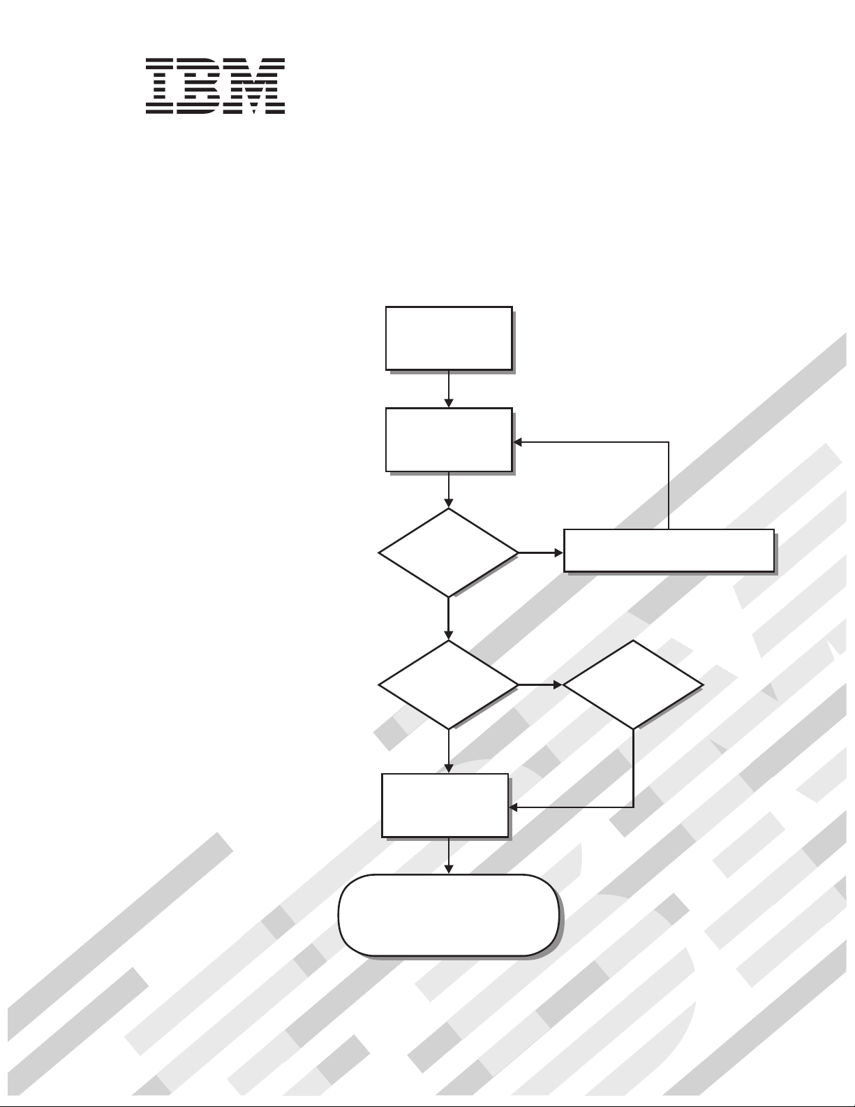
Start the computer
Did the computer
start correctly?
Ye s
Do you plan to
use Windows XP or
Red Hat Linux?
Ye s
Complete the setup
program
No
No
Go to the Computer Support
flowchart inside this cover
Install another
operating system
System is ready to use.
• Click on your desktop
Access IBM
and register your computer
• Install options and applications
Page 2
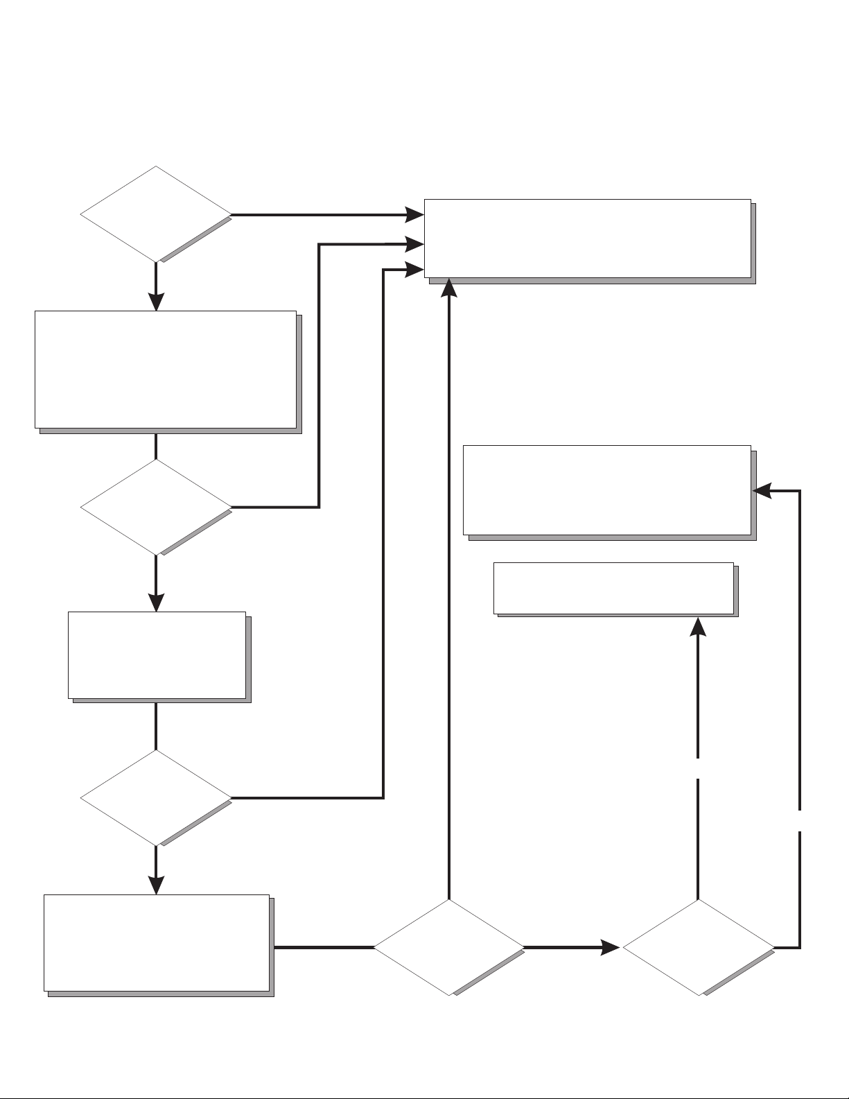
Computer Support
Computer working
properly?
Ye s
No
Check all cables for loose connections
and verify that all optional devices you
installed are on the compatibility matrix.
You can view the atcompatibility matrix
http://www.pc.ibm.com/us/compat/
intellistation/
Problem
solved?
Ye s
No
Register your computer. Go to
http://www.ibm.com/pc/register/
View information about IBM Support
Line at
http://www.ibm.com/services/sl/products/
or view support telephone numbers at
http://www.ibm.com/planetwide/
View support telephone numbers at
http://www.ibm.com/planetwide/
Use the troubleshooting
information provided with
your computer to determine
the cause of the problem
and the action to take.
Problem
solved?
Ye s
No
Flash the latest levels of BIOS,
and download the latest level of
diagnostics. You can download
this code at
http://www.ibm.com/pc/support/
Ye s
Problem
solved?
No
Hardware
Software
Hardware
or Software
problem?
Page 3

IBM IntelliStation Z Pro
Ty pe 6221
Installation Guide
Page 4

©
US
Note:
Before using this information and the product it supports, read the general information in Appendix B, “IBM Statement of Limited
Warranty Z125-4753-07 11/2002,” on page 61 and Appendix C, “Notices,” on page 77.
Fifth (March 2004)
Copyright International Business Machines Corporation 2004. All rights reserved.
Government Users Restricted Rights – Use, duplication or disclosure restricted by GSA ADP Schedule Contract
with IBM Corp.
Page 5

©
Contents
Safety . . . . . . . . . . . . . . . . . . . . . . . . . . . .v
Chapter 1. Introduction . . . . . . . . . . . . . . . . . . . . . .1
About your documentation CD . . . . . . . . . . . . . . . . . . . .2
System requirements . . . . . . . . . . . . . . . . . . . . . .2
Starting the IBM Documentation Browser . . . . . . . . . . . . . . .2
Using the IBM Documentation Browser . . . . . . . . . . . . . . .2
Using the search feature . . . . . . . . . . . . . . . . . . . . .3
Notices and statements used in this book . . . . . . . . . . . . . . .3
Related publications . . . . . . . . . . . . . . . . . . . . . . .4
Inventory checklist . . . . . . . . . . . . . . . . . . . . . . . .4
Features and specifications . . . . . . . . . . . . . . . . . . . . .5
Controls and indicators . . . . . . . . . . . . . . . . . . . . . .6
Chapter 2. Installing the hardware . . . . . . . . . . . . . . . . .9
Selecting a location for your computer . . . . . . . . . . . . . . . . .9
Arranging your workspace . . . . . . . . . . . . . . . . . . . . .9
Comfort . . . . . . . . . . . . . . . . . . . . . . . . . . .9
Glare and lighting . . . . . . . . . . . . . . . . . . . . . . .9
Air circulation . . . . . . . . . . . . . . . . . . . . . . . .10
Electrical outlets and cable lengths . . . . . . . . . . . . . . . .10
Installing options . . . . . . . . . . . . . . . . . . . . . . . .10
Major components of your computer . . . . . . . . . . . . . . . .11
System-board option connectors . . . . . . . . . . . . . . . . .11
System-board internal connectors . . . . . . . . . . . . . . . . .12
System-board external connectors . . . . . . . . . . . . . . . . .12
Installation guidelines . . . . . . . . . . . . . . . . . . . . .12
System reliability considerations . . . . . . . . . . . . . . . . .13
Handling static-sensitive devices . . . . . . . . . . . . . . . . .13
Removing the side cover . . . . . . . . . . . . . . . . . . . .14
Removing and installing the support bracket . . . . . . . . . . . . .15
Working with adapters . . . . . . . . . . . . . . . . . . . . .16
Installing internal drives . . . . . . . . . . . . . . . . . . . . .20
Installing memory modules . . . . . . . . . . . . . . . . . . .26
Installing an additional microprocessor . . . . . . . . . . . . . . .29
Installing a security rope clip . . . . . . . . . . . . . . . . . . .32
Completing the installation . . . . . . . . . . . . . . . . . . . . .32
Replacing the side cover . . . . . . . . . . . . . . . . . . . .33
Cabling the computer . . . . . . . . . . . . . . . . . . . . .34
Turning on the computer . . . . . . . . . . . . . . . . . . . .34
Running the operating system setup program . . . . . . . . . . . .35
Turning off the computer . . . . . . . . . . . . . . . . . . . . .36
Copyright IBM Corp. 2004
Chapter 3. Installing software . . . . . . . . . . . . . . . . . . .37
Viewing the license agreement . . . . . . . . . . . . . . . . . . .37
Using Access IBM . . . . . . . . . . . . . . . . . . . . . . . .37
Using the built-in configuration programs . . . . . . . . . . . . . . .38
Starting the Configuration/Setup Utility program . . . . . . . . . . . .38
Starting the LSI Logic Configuration Utility program . . . . . . . . . .38
Using ServeRAID Manager . . . . . . . . . . . . . . . . . . .39
Chapter 4. Completing the installation . . . . . . . . . . . . . . .49
Recording important numbers . . . . . . . . . . . . . . . . . . .49
iii
Page 6

iv
Registering your computer . . . . . . . . . . . . . . . . . . . . .49
Creating an emergency recovery-repair diskette in Windows . . . . . . . .50
Creating an IBM Enhanced Diagnostics diskette in Windows . . . . . . . .50
Chapter 5. Solving problems . . . . . . . . . . . . . . . . . . .51
Diagnostic tools overview . . . . . . . . . . . . . . . . . . . . .51
Power-on self-test (POST) . . . . . . . . . . . . . . . . . . . . .52
POST beep codes . . . . . . . . . . . . . . . . . . . . . .52
POST error messages . . . . . . . . . . . . . . . . . . . . .52
Troubleshooting charts . . . . . . . . . . . . . . . . . . . . . .53
CD-ROM drive problems . . . . . . . . . . . . . . . . . . . .53
Diskette drive problems . . . . . . . . . . . . . . . . . . . . .54
Hard disk drive problems . . . . . . . . . . . . . . . . . . . .54
Keyboard, mouse, or pointing-device problems . . . . . . . . . . . .54
Memory problems . . . . . . . . . . . . . . . . . . . . . . .55
Microprocessor problems . . . . . . . . . . . . . . . . . . . .55
Monitor problems . . . . . . . . . . . . . . . . . . . . . . .55
Power problems . . . . . . . . . . . . . . . . . . . . . . .56
System-board error LEDs . . . . . . . . . . . . . . . . . . . . .57
Product Recovery program . . . . . . . . . . . . . . . . . . . .57
Appendix A. Getting help and technical assistance . . . . . . . . . .59
Before you call . . . . . . . . . . . . . . . . . . . . . . . . .59
Using the documentation . . . . . . . . . . . . . . . . . . . . .59
Getting help and information from the World Wide Web . . . . . . . . . .60
Software service and support . . . . . . . . . . . . . . . . . . .60
Hardware service and support . . . . . . . . . . . . . . . . . . .60
Appendix B. IBM Statement of Limited Warranty Z125-4753-07 11/2002 . .61
Part 1 - General Terms . . . . . . . . . . . . . . . . . . . . . .61
Part 2 - Country-unique Terms . . . . . . . . . . . . . . . . . . .64
Part 3 - Warranty Information . . . . . . . . . . . . . . . . . . .75
Appendix C. Notices . . . . . . . . . . . . . . . . . . . . . .77
Edition notice . . . . . . . . . . . . . . . . . . . . . . . . .77
Trademarks . . . . . . . . . . . . . . . . . . . . . . . . . .78
Important notes . . . . . . . . . . . . . . . . . . . . . . . . .78
Product recycling and disposal . . . . . . . . . . . . . . . . . . .79
Battery return program . . . . . . . . . . . . . . . . . . . . . .80
Electronic emission notices . . . . . . . . . . . . . . . . . . . .80
Federal Communications Commission (FCC) statement . . . . . . . . .80
Industry Canada Class A emission compliance statement . . . . . . . .81
Australia and New Zealand Class A statement . . . . . . . . . . . .81
United Kingdom telecommunications safety requirement . . . . . . . . .81
European Union EMC Directive conformance statement . . . . . . . . .81
Taiwanese Class A warning statement . . . . . . . . . . . . . . .81
Chinese Class A warning statement . . . . . . . . . . . . . . . .82
Japanese Voluntary Control Council for Interference (VCCI) statement . . .82
Power cords . . . . . . . . . . . . . . . . . . . . . . . . . .82
Index . . . . . . . . . . . . . . . . . . . . . . . . . . . .85
IBM IntelliStation Z Pro Type 6221: Installation Guide
Page 7
©
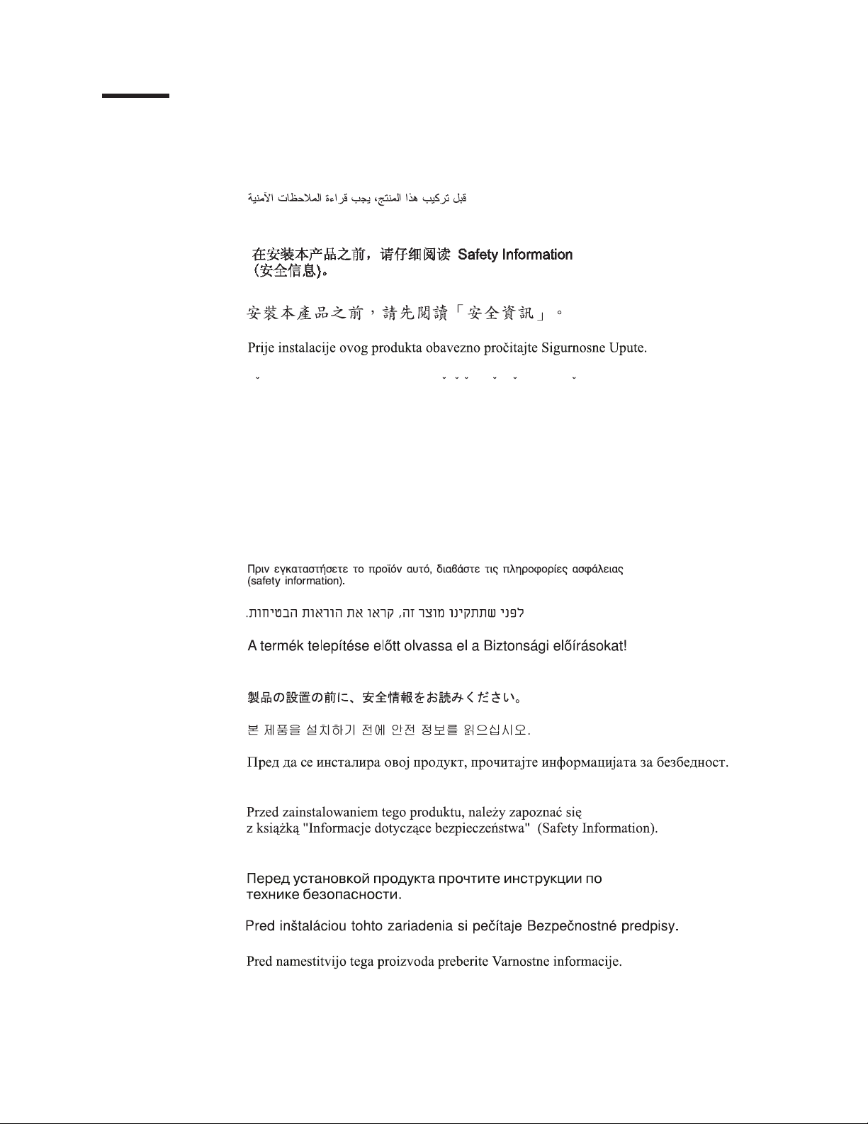
Safety
Before installing this product, read the Safety Information.
Antes de instalar este produto, leia as Informações de Segurança.
Pred instalací tohoto produktu si prectete prírucku bezpecnostních instrukcí.
Læs sikkerhedsforskrifterne, før du installerer dette produkt.
Lees voordat u dit product installeert eerst de veiligheidsvoorschriften.
Ennen kuin asennat tämän tuotteen, lue turvaohjeet kohdasta Safety Information.
Avant d’installer ce produit, lisez les consignes de sécurité.
Vor der Installation dieses Produkts die Sicherheitshinweise lesen.
Prima di installare questo prodotto, leggere le Informazioni sulla Sicurezza.
Les sikkerhetsinformasjonen (Safety Information) før du installerer dette produktet.
Copyright IBM Corp. 2004
Antes de instalar este produto, leia as Informações sobre Segurança.
Antes de instalar este producto, lea la información de seguridad.
Läs säkerhetsinformationen innan du installerar den här produkten.
v
Page 8

To
v Do
v
v
v
v
v
v
To
To
1.
2.
3.
4.
5.
1.
2.
3.
4.
vi
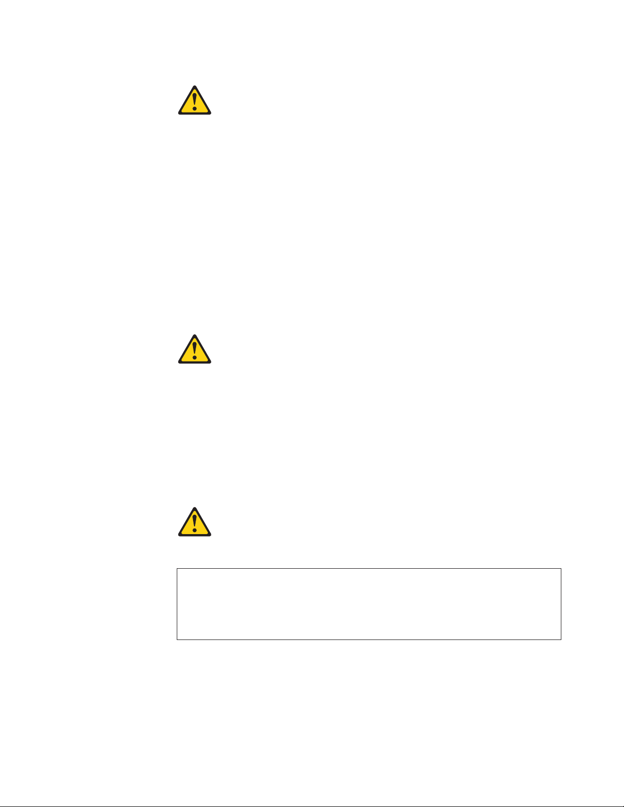
Statement 1:
DANGER
Electrical
current from power, telephone, and communication cables is
hazardous.
avoid a shock hazard:
not connect or disconnect any cables or perform installation,
maintenance, or reconfiguration of this product during an electrical
storm.
Connect all power cords to a properly wired and grounded electrical
outlet.
Connect to properly wired outlets any equipment that will be attached to
this product.
When possible, use one hand only to connect or disconnect signal
cables.
Never turn on any equipment when there is evidence of fire, water, or
structural damage.
Disconnect the attached power cords, telecommunications systems,
networks, and modems before you open the device covers, unless
instructed otherwise in the installation and configuration procedures.
Connect and disconnect cables as described in the following table when
installing, moving, or opening covers on this product or attached
devices.
Connect:
Turn everything OFF.
First, attach all cables to devices.
Attach signal cables to connectors.
Attach power cords to outlet.
Turn device ON.
Disconnect:
Turn everything OFF.
First, remove power cords from outlet.
Remove signal cables from connectors.
Remove all cables from devices.
IBM IntelliStation Z Pro Type 6221: Installation Guide
Page 9
a
Do
v
v
v
of
v Do
v
Statement 2:
CAUTION:
When replacing the lithium battery, use only IBM Part Number 33F8354 or an
equivalent type battery recommended by the manufacturer. If your system has
module containing a lithium battery, replace it only with the same module
type made by the same manufacturer. The battery contains lithium and can
explode if not properly used, handled, or disposed of.
not:
Throw or immerse into water
Heat to more than 100°C (212°F)
Repair or disassemble
Dispose
the battery as required by local ordinances or regulations.
Statement 3:
CAUTION:
When laser products (such as CD-ROMs, DVD drives, fiber optic devices, or
transmitters) are installed, note the following:
not remove the covers. Removing the covers of the laser product could
result in exposure to hazardous laser radiation. There are no serviceable
parts inside the device.
Use of controls or adjustments or performance of procedures other than
those specified herein might result in hazardous radiation exposure.
DANGER
Some
laser products contain an embedded Class 3A or Class 3B laser
diode. Note the following.
Laser radiation when open. Do not stare into the beam, do not view directly
with optical instruments, and avoid direct exposure to the beam.
Safety
vii
Page 10
≥ 18 kg
≥ 32 kg
≥ 55 kg
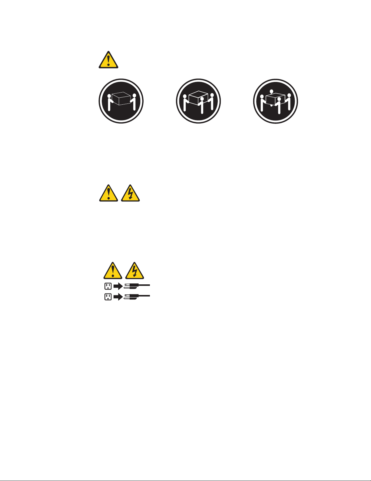
Statement 4:
(39.7 lb)
(70.5 lb)
(121.2 lb)
CAUTION:
Use safe practices when lifting.
Statement 5:
CAUTION:
The power control button on the device and the power switch on the power
supply do not turn off the electrical current supplied to the device. The device
also might have more than one power cord. To remove all electrical current
from the device, ensure that all power cords are disconnected from the power
source.
2
1
viii
IBM IntelliStation Z Pro Type 6221: Installation Guide
Page 11
a
Do
No
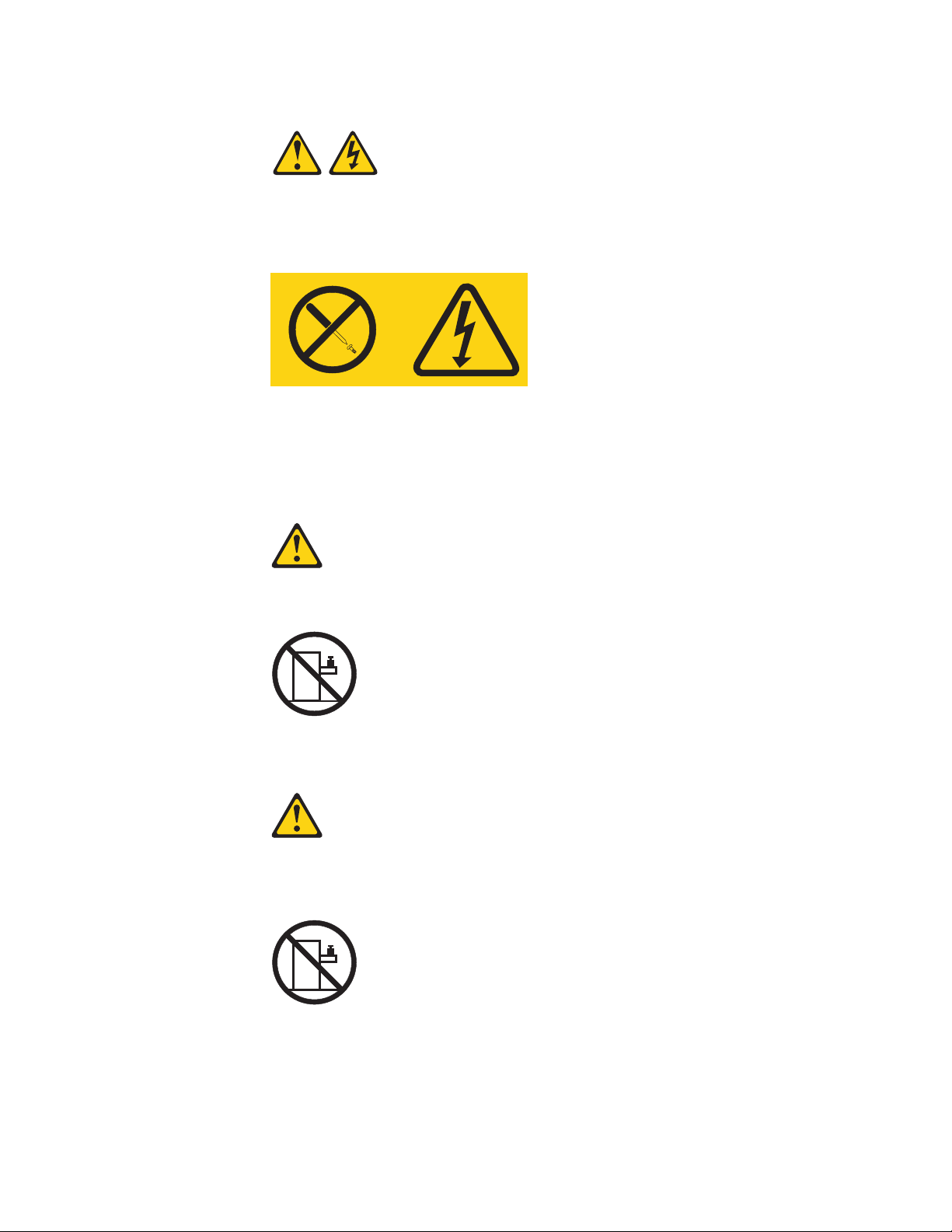
Statement 8:
CAUTION:
Never remove the cover on a power supply or any part that has the following
label attached.
Hazardous voltage, current, and energy levels are present inside any
component that has this label attached. There are no serviceable parts inside
these components. If you suspect a problem with one of these parts, contact
service technician.
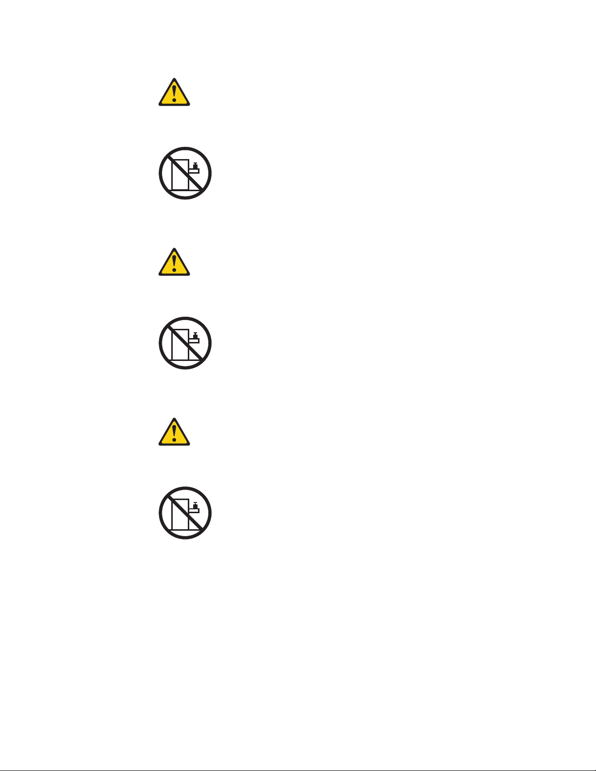
Statement 23
CAUTION:
not place any object weighing more than 50 kg (110 lb) on top of rack-mounted
devices.
>50 kg (110 lb)
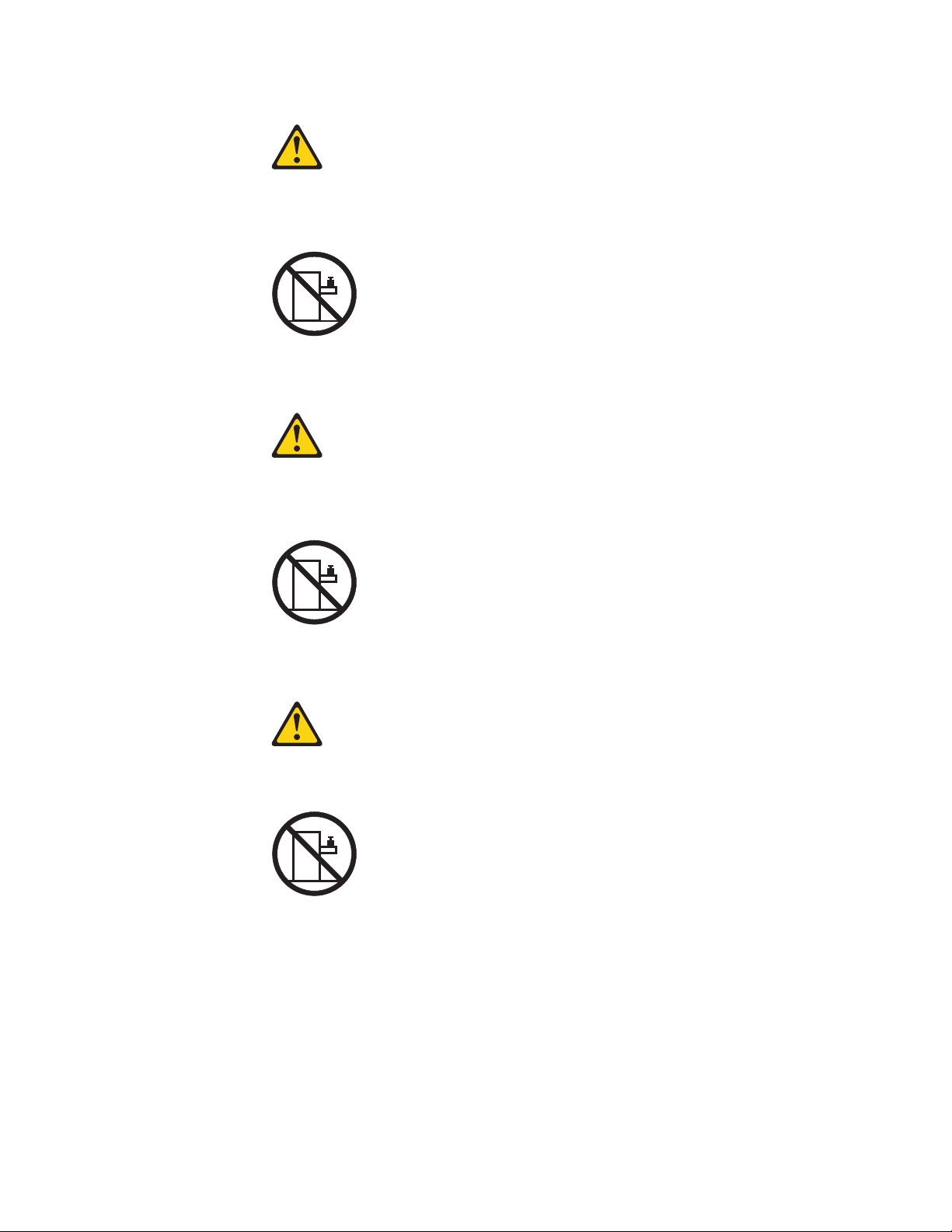
Declaración 23
PRECAUCIÓN:
coloque ningún objeto que pese más de 50 kg (110 libras) encima de los
dispositivos montados en bastidor.
>50 kg (110 libras)
Safety
ix
Page 12
Ne
x
Hinweis 23
ACHTUNG:
Keine Gegenstände, die mehr als 50 kg wiegen, auf Rack-Einheiten ablegen.
>50 kg
Notice nø 23
ATTENTION:
posez pas d’objet dont le poids dépasse 50 kg sur les unités montées en armoire.
>50 kg
Varningsmeddelande 23
VARNING:
Placera inte något föremål som väger mer än 50 kg ovanpå rackmonterade enheter.
>50 kg
IBM IntelliStation Z Pro Type 6221: Installation Guide
Page 13
in
Merknad 23
ADVARSEL:
Ikke sett gjenstander som veier mer enn 50 kg oppå enheter som er montert i et
kabinett.
>50 kg
Avviso 23
ATTENZIONE:
Non poggiare oggetti che pesano più di 50 kg sulla parte superiore delle unità montate
rack.
>50 kg
Turvaohje 23
Varoitus:
Telineeseen asennettujen laitteiden päälle ei saa asettaa yli 50 kilon painoista esinettä.
>50 kg
Safety
xi
Page 14
Voorschrift 23
WAARSCHUWING:
Plaats geen objecten die meer dan 50 kg wegen op apparaten die in het rek zijn
gemonteerd.
>50 kg
Forskrift 23
Pas på!:
Anbring ikke genstande, der vejer mere end 50 kg, oven på enheder, der er monteret i
rack.
>50 kg
Instrução 23
CUIDADO:
Não coloque nenhum objeto com peso superior a 50 kg (110 lbs.) sobre dispositivos
montados em rack.
>50 kg (110 lbs)
xii
IBM IntelliStation Z Pro Type 6221: Installation Guide
Page 15
50
110
23
23
50
110
50
50
Safety
xiii
Page 16
23
50
23
·
50
50
> 50 Kg
50
110
110
23
50
xiv
IBM IntelliStation Z Pro Type 6221: Installation Guide
Page 17
23
110
50
50
110
23
50 110
50 110
50
23
50
Safety
xv
Page 18
23
50 110
50
110
23
50 110
50 110
50 110
23
50
xvi
IBM IntelliStation Z Pro Type 6221: Installation Guide
Page 19
23
50 110
50 110
50 110
23
50 110
Safety
xvii
Page 20

Be
Instrução 23
CUIDADO:
Não coloque nenhum objeto com peso superior a 50 kg (110 lbs.) sobre dispositivos
montados em rack.
>50 kg (110 lbs)
WARNING: Handling the cord on this product or cords associated with accessories
sold with this product, will expose you to lead, a chemical known to the State of
California to cause cancer, and birth defects or other reproductive harm. Wash
hands after handling.
ADVERTENCIA: El contacto con el cable de este producto o con cables de
accesorios que se venden junto con este producto, pueden exponerle al plomo, un
elemento químico que en el estado de California de los Estados Unidos está
considerado como un causante de cancer y de defectos congénitos, además de
otros riesgos reproductivos. Lávese las manos después de usar el producto.
Important:
All caution and danger statements in this documentation begin with a number. This
number is used to cross reference an English caution or danger statement with
translated versions of the caution or danger statement in the IBM Safety Information
book.
For example, if a caution statement begins with a number 1, translations for that
caution statement appear in the IBM Safety Information book under statement 1.
sure to read all caution and danger statements in this documentation before
performing the instructions. Read any additional safety information that comes with
your server or optional device before you install the device.
xviii
IBM IntelliStation Z Pro Type 6221: Installation Guide
Page 21

Z
v
v
v
If
If
to
XP or
To
©
Chapter 1. Introduction
Thank you for purchasing an IBM
®
IntelliStation
®
Pro computer. This Installation
Guide provides the information that is needed to:
Set up and cable your computer
Start and configure your computer
Set up your operating system
Packaged
with the Installation Guide is the Device Drivers and IBM Enhanced
Diagnostics CD, which contains device drivers and hardware-specific support
software.
The IBM IntelliStation Documentation CD is also included. This CD provides
detailed information about your computer. See “About your documentation CD” on
page 2 for more information.
you have access to the World Wide Web, you can obtain up-to-date information
about your IntelliStation Z Pro model and other IBM products at
http://www.ibm.com/intellistation/.
The computer model and serial numbers are on labels on the bottom of the
computer and on the lower-right side of the bezel. You will need these numbers to
register your computer with IBM.
Note: Your computer keys cannot be duplicated by locksmiths. If you lose them,
order replacement keys from the key manufacturer. The key serial number and the
telephone number of the manufacturer are on a tag attached to the keys.
you plan to install your computer in a rack, you need to purchase a
Tower-to-Rack Conversion Kit. For a list of supported options for your computer, go
http://www.ibm.com/pc/; then, select your country and navigate to the list of
options for your computer.
Your computer comes with Microsoft
®
Windows
®
Red Hat Enterprise Linux
Workstation preinstalled (depending on your model).
install another operating system, follow the instructions in the documentation
provided with the operating system and any updates. Then, follow the instructions in
the readme file on the Device Drivers and IBM Enhanced Diagnostics CD to install
the support software.
Note: If you install another operating system, you might need additional software or
device drivers. Hardware-specific support software is available on the Device
Drivers and IBM Enhanced Diagnostics CD. If you experience problems with the
device drivers installed from this CD, you can obtain the latest device drivers at
http://www.ibm.com/pc/support/.
Before installing any operating system, be sure that you obtain the latest updates.
Contact the operating system manufacturer or, if applicable, check the
manufacturer’s World Wide Web site to obtain the updates.
Additional information about operating systems is posted periodically at
http://www.ibm.com/pc/support/.
Copyright IBM Corp. 2004
1
Page 22

In
To
v
v
v 32 MB of
v
v If
v If
– If
– If
sh
a
2
The latest version of this publication is available from the IBM Web site. Go to
http://www.ibm.com/ and click Support & downloads. In the Technical support
keyword search field, type 6221 and click Go. A list of publications for your
computer is displayed.
About your documentation CD
Your IBM system comes with a documentation CD, which contains documentation
for your system in Portable Document Format (PDF) and includes the IBM
Documentation Browser to help you find information quickly.
addition to the documentation CD, your system comes with an Installation Guide,
which contains basic installation instructions for your system. If your system is
rack-optimized, it also comes with Rack Installation Instructions, which contains a
rack-installation template and basic instructions for installing your system into a
rack.
System requirements
run the documentation CD, your system must have the following minimum
hardware and software:
Microsoft Windows NT
2000, or Red Hat Linux.
RAM.
™
Pentium
100 MHz Intel
Adobe Acrobat Reader 3.0 (or later) or xpdf, which comes with Linux operating
systems.
®
4.0 (with Service Pack 3 or later), Windows 98, Windows
®
microprocessor.
Note: Adobe Acrobat Reader software is included on the documentation CD,
and you can install it when you run the IBM Documentation Browser.
Starting the IBM Documentation Browser
Use one of the following procedures to start the Documentation Browser:
Autostart is enabled, insert the documentation CD into your CD-ROM drive.
The Documentation Browser will start automatically.
Autostart is disabled or is not enabled for all users:
you are using a Windows operating system, insert the CD into your
CD-ROM drive; then, click start → Run. In the Open field, type
e:\win32.bat
where e is the drive letter of your CD-ROM drive, and click OK.
you are using Red Hat Linux, insert the CD into your CD-ROM drive and
run the following command from the /mnt/cdrom directory:
runLinux.sh
Using the IBM Documentation Browser
Use the IBM Documentation Browser to browse the contents of the documentation
CD, select from a list of available topics, see brief descriptions of the selected
topics, and view selected topics using Adobe Acrobat Reader or xpdf. The
Documentation Browser automatically detects the regional settings in use on your
system and presents the information in the language for that region (if available). If
topic is not available in a particular language, the English version is displayed.
Click Help for detailed information about using the IBM Documentation Browser.
IBM IntelliStation Z Pro Type 6221: Installation Guide
Page 23

1.
2.
3.
1.
2.
on
3.
4.
v
v
v
v
to
v
Complete the following steps to use the Documentation Browser:
Select your product from the Product drop-down list.
The Topics list appears. It lists all topics that pertain to the selected product.
Topics are in folders or under other topics. A plus sign (+) appears beside each
folder or topic that has additional topics under it. Click the plus sign to display
the additional topics.
Click a topic to select it.
When you select a topic, a description of the topic contents appears in the
Description field.
Note: To select multiple topics, press and hold down the Ctrl key while
selecting your topics.
View selected topics.
Click View Book. Adobe Acrobat Reader or xpdf starts, and the selected topics
are displayed.
Using the search feature
Complete the following steps to use the Documentation Browser search feature:
Type a key word in the Search field.
Click Search. The topics containing the search word are listed in order based
the number of occurrences.
Click a file to open it.
Press Ctrl+F to use the Adobe Acrobat search function or Alt+F to use the xpdf
search function to search within the file.
Notices and statements used in this book
The caution and danger statements used in this book also appear in the multilingual
Safety Information book that is viewable through Access IBM and on the IBM
IntelliStation Documentation CD. Each statement is numbered for reference to the
corresponding statement in the Safety Information book.
The notice and statement definitions are:
Notes: These notices provide important tips, guidance, or advice.
Important: These notices provide information that might help you avoid
inconvenient or problem situations.
Attention: These notices indicate possible damage to programs, devices, or
data. An attention notice is placed just before the instruction or situation in which
damage could occur.
Caution: These statements indicate situations that can be potentially hazardous
you. A caution statement is placed just before the description of a potentially
hazardous procedure step or situation.
Danger: These statements indicate situations that can be potentially lethal or
extremely hazardous to you. A danger statement is placed just before the
description of a potentially lethal or extremely hazardous procedure step or
situation.
Chapter 1. Introduction
3
Page 24

v
v
v
v
v
v
v
v
v
v
v
v
If
4
Related publications
The following documentation contains additional information about your computer.
Because your computer comes with IBM-preinstalled software, you might be able to
view some of these documents in Access IBM. See “Using Access IBM” on page
37. The following IBM documents can also be found at http://www.ibm.com/.
User’s Guide
This publication contains detailed information about your computer and how to
use and configure the functions of the computer.
Hardware Maintenance Manual
This publication contains information for trained service technicians. It can be
found at http://www.ibm.com/pc/support/.
Readme files on the Device Drivers and IBM Enhanced Diagnostics CD
Several readme files on this CD contain diagnostic tools and preinstalled device
drivers. Other readme files on this CD contain information about the various
adapters and devices that might be installed in or attached to your computer.
Safety Information book
This publication, accessible through Access IBM, contains multilingual caution
and danger statements.
Inventory checklist
Take an inventory of items as you unpack them to ensure that you have all of the
components. If any items are missing or damaged, contact your place of purchase.
The following is a list of items shipped with your IBM IntelliStation Z Pro computer:
One keyboard
One mouse
One power cord (9-ft line cord)
One power-control button shield
Dual-analog monitor pigtail cable (some models)
One Device Drivers and IBM Enhanced Diagnostics CD
One IBM IntelliStation Documentation CD
This Installation Guide
you are missing an item, contact your place of purchase.
IBM IntelliStation Z Pro Type 6221: Installation Guide
Page 25

v
v
2 MB
v
v
v
v
v
v
v
v
v
–
–
–
v
v
v
v
v
v
v
v
v
v
v
v
–
–
–
v
v
v
MB
v
v
v
v
v
v
v
v
v
–
–
–
–
–
–
v
v
v
–
–
v
v
v
v
v
v
Features and specifications
The following table provides a summary of the features and specifications of your
IntelliStation Z Pro Type 6221 computer. Some features are not available on all
models.
Note: You can use the Configuration/Setup Utility program in your computer to
determine the specific type of microprocessor on your system board.
Table 1. Features and specifications
Microprocessor:
Intel Xeon Processor
512 KB Level-2, 1 MB Level-3, or
Level-3 cache
533 MHz front-side bus (FSB)
Support for up to two
microprocessors
Memory:
Minimum: 256 MB
Maximum: 8 GB
Type: PC2100, double-data-rate
(DDR)
Connectors: four dual inline memory
module (DIMM) connectors, two-way
interleaved
Internal
Drives:
Diskette: 1.44 MB (two mode)
Hard disk drive: IDE or SCSI
One of the following optical drives:
CD-ROM: IDE
DVD/CD-RW combo: IDE
CD-RW: IDE
Expansion
bays:
Three slim-high, 3.5-inch drive bays
(one hard disk drive installed in some
models)
Two 5.25-inch bays (optical drive
installed in one bay)
One 3.5-inch removable-media drive
bay (diskette drive installed)
Electrical input:
Sine-wave input (50 or 60 Hz)
required
Input voltage and frequency ranges
automatically selected
Input voltage low range:
Minimum: 100 V ac
Maximum: 127 V ac
Input voltage high range:
v
Minimum: 200 V ac
Maximum: 240 V ac
Input kilovolt-amperes (kVA)
v
approximately:
Minimum: 0.15 kVA
Maximum: 0.80 kVA
Integrated functions:
Broadcom 5703 10/100/1000 Ethernet
controller on the system board with
RJ-45 Ethernet port
Two serial ports
One parallel port
(Some models) Two IEEE 1394
(FireWire) ports (four-pin on front,
six-pin on rear)
Integrated SCSI controller with RAID
capabilities and two Ultra 320 SCSI
ports (one internal, one optional
external)
Four Universal Serial Bus (USB) v2.0
ports (two on front and two on rear of
enclosure)
Keyboard port
Mouse port
Audio ports
Line out (front and rear)
Mic (front and rear)
Line in (rear)
ATA-100 dual-channel IDE controller
v
expansion slots:
PCI
Four PCI-X 100 MHz/64-bit
One PCI 33 MHz/32-bit
Power
One 425 watt output (115-230 V ac)
Cooling:
Two speed-controlled system fans
Heat output:
Approximate heat output in British thermal
units (Btu) per hour
Minimum configuration: 341 Btu/hour
(100 watts)
Maximum configuration: 2082 Btu/hour
(607 watts)
Environment:
Air temperature:
Computer on: 10° to 35°C (50° to
95°F)
Altitude: 0 to 2134 m (7000 ft)
Computer off: -40° to +60°C (-40° to
140°F)
Maximum altitude: 2133 m (7000 ft)
v
Humidity (operating and storage): 8% to
80%
supply:
Video adapter: Accelerated graphics port
(AGP) Pro 50 video with one of the following:
Matrox Millennium G450 (DVI-I) 4X with 32
double-data-rate (DDR) synchronous
dynamic random access memory (SDRAM)
video memory and a single DVI-I or dual
analog connectors (or dual VGA monitor
capability with the pigtail cable that came
with the system)
NVIDIA Quadro4 NVS 280 (LFH-60), AGP
8X, with 64 MB DDR SDRAM video
memory and dual analog connectors (or
dual digital monitor capability with the
purchase of an additional pigtail cable)
NVIDIA Quadro4 980XGL (DVI-I), AGP 8X,
with 128 MB DDR SDRAM video memory
and dual DVI-I connectors
NVIDIA Quadro FX 1000 (DVI-I), AGP 8X,
with 128 MB DDR2 SDRAM video memory
with dual DVI-I connectors
NVIDIA Quadro FX 1100 (DVI-I), AGP 8X,
with 128 MB DDR SDRAM video memory
with dual DVI-I connecctors
NVIDIA Quadro FX 3000 (DVI-I), AGP 8X,
with 256 MB DDR SDRAM video memory
with dual DVI-I connectors
3Dlabs Wildcat4 7110 (DVI-I), AGP 8X, with
128 MB texture buffer DDR SDRAM video
memory and 128 MB frame buffer video
memory, and dual DVI-I connectors
Acoustical noise emissions:
Sound power, idle: 5.3 bel maximum
Sound power, operating: 5.6 bel maximum
Size:
Height: 438 mm (17.25 in.)
Depth: 483 mm (19 in.)
Width: 165 mm (6.5 in.)
Weight: 16.3 kg (36 lb) to 20.8 kg (45.8 lb)
depending upon configuration
Chapter 1. Introduction
5
Page 26
on
6
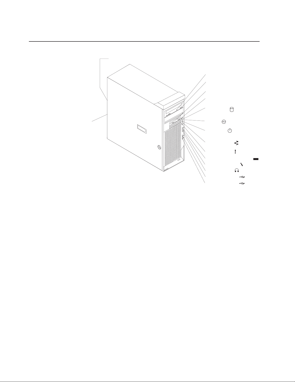
Controls and indicators
Ethernet link status LED
CD-ROM drive
activity LED
CD-eject
button
Diskette drive
activity LED
Diskette-eject
button
Hard disk drive
activity LED
Ethernet
transmit/receive
activity LED
CD-eject button
Press this button to release a CD from the CD-ROM drive.
CD-ROM drive activity LED
When this LED is lit, it indicates that the CD-ROM drive is in use.
Diskette drive activity LED
When this LED is lit, it indicates that the diskette drive is in use.
Diskette-eject button
Press this button to release a diskette from the diskette drive.
Ethernet link status LED
This LED is on the Ethernet connector on the back of the computer. When
this LED is lit, it indicates that there is an active connection on the Ethernet
port.
Power-on
94
13
LED
Power-control
button
Ethernet transmit/
receive activity LED
System error LED
IEEE 1394 (FireWire) connector
1394
Microphone connector
Line out connector
USB port A connector
USB port B connector
Ethernet transmit/receive activity LED
When this LED is lit, it indicates that there is activity between the computer
and the network. There are two Ethernet transmit/receive activity LEDs: one
the front bezel and the other on the Ethernet connector on the rear of
the computer.
Hard disk drive activity LED
When this LED is flashing, it indicates that a hard disk drive is in use.
IEEE 1394 (FireWire) connector (some models)
This connector is used to connect IEEE 1394 devices to your computer.
IBM IntelliStation Z Pro Type 6221: Installation Guide
Page 27

on
Line-out connector (green)
This connector sends stereo audio signals from the computer to external
devices, such as speakers with built-in amplifiers, headphones, or the audio
line-in jack on a stereo system.
Microphone connector (pink)
This connector is used to connect a microphone to record voice or other
sounds on the hard disk. You can also use this connector (and a
microphone) with speech recognition software.
Power-control button
Press this button to turn the computer on and off manually. You can install a
circular disk, called the power-control button shield, over the power-control
button to prevent accidental manual power-off. This disk is provided with
your computer.
Power-on LED
When this LED is lit and does not flash, it indicates that the computer is
turned on. When this LED is flashing, it indicates that the computer is off
and still connected to an ac power source (standby mode).
System error LED
When this LED is lit, it indicates that a system error has occurred. An LED
the system board might also be lit to help isolate the error. See
“System-board error LEDs” on page 57 for additional information. Detailed
troubleshooting information is in the User’s Guide on the IBM IntelliStation
Documentation CD.
USB ports
Use these automatically configures ports to connect universal serial bus
(USB) v2.0 devices to your computer, using Plug and Play technology.
Chapter 1. Introduction
7
Page 28

8
IBM IntelliStation Z Pro Type 6221: Installation Guide
Page 29

in
To
on a
in a
©
Chapter 2. Installing the hardware
This chapter provides instructions to help you install the hardware and options in
your computer. This section is for all users, but is written with the experienced user
mind. If you need more detailed installation information for options, see the
User’s Guide on the IBM IntelliStation Documentation CD.
Selecting a location for your computer
Make sure you have an adequate number of properly grounded electrical outlets for
the computer, monitor, and any other devices. Select a location for the computer
where it will remain dry. Leave about 50 mm (2 in.) of space around the computer
for proper air circulation. For information about arranging your computer and
ease-of-use, see the following sections.
Arranging your workspace
work area to suit your needs and the kind of work you do. Your comfort is of
foremost importance, but light sources, air circulation, and the location of electrical
outlets can also affect the way you arrange your workspace.
Comfort
The following guidelines will help you decide what working position suits you best.
Choose a chair to reduce fatigue from sitting in the same position for long periods.
The backrest and seat should adjust independently and provide good support. The
seat should have a curved front to relieve pressure on the thighs. Adjust the seat so
that your thighs are parallel to the floor and your feet are either flat on the floor, or
When using the keyboard, keep your forearms parallel to the floor and your wrists
your hands and fingers relaxed. Change the angle of the keyboard for maximum
comfort by adjusting the position of the keyboard feet.
Adjust the monitor so that the top of the screen is at, or slightly below, eye level.
Place the monitor at a comfortable viewing distance, usually 51 to 61 cm (20 to 24
in.), and position it so that you can view it without having to twist your body.
Glare and lighting
Position the monitor to minimize glare and reflections from overhead lights,
windows, and other light sources. Place the monitor at right angles to light sources
whenever possible. Reduce overhead lighting, if necessary, by turning off lights or
using lower wattage bulbs. If you install the monitor near a window, use curtains or
blinds to block the sunlight. You might have to adjust the Brightness and Contrast
controls on the monitor as the lighting changes throughout the day.
get the most from your computer, arrange both the equipment you use and your
footrest.
neutral, comfortable position. Try to keep a light touch on the keyboard, and
Copyright IBM Corp. 2004
Where it is impossible to avoid reflections or to adjust the lighting, place an
antiglare filter over the screen. However, these filters might affect the clarity of the
screen image; try them only after you have exhausted other methods of reducing
glare.
9
Page 30

v
v
If
10
Dust compounds problems associated with glare. Clean your monitor screen
periodically using a soft cloth moistened with a nonabrasive, liquid glass cleaner.
Air circulation
Your computer and monitor produce heat. The computer fan pulls in fresh air and
forces out hot air. The monitor lets hot air escape through vents. Blocking the air
vents can cause overheating, possibly resulting in malfunction or damage. Place the
computer and monitor so that nothing blocks the air vents; usually 51 mm (2 in.) of
air space is sufficient. Also, make sure the vented air is not blowing on someone
else.
Electrical outlets and cable lengths
The location of electrical outlets and the length of device power cords and cables
might determine the final placement of your computer.
When arranging your work space:
Avoid the use of extension cords. Whenever possible, plug the computer power
cord directly into an electrical outlet.
Keep power cords and cables neatly routed away from walkways and other areas
where they might be accidentally dislodged.
For more information about power cords, see “Power cords” on page 82
Installing options
This section contains instructions that will help you to install hardware options in
your IntelliStation Z Pro computer. This section is for all users, but it is written with
the experienced user in mind. If you need more detailed installation information, see
the User’s Guide on the IBM IntelliStation Documentation CD.
you have no options to install, continue with “Cabling the computer” on page 34.
IBM IntelliStation Z Pro Type 6221: Installation Guide
Page 31
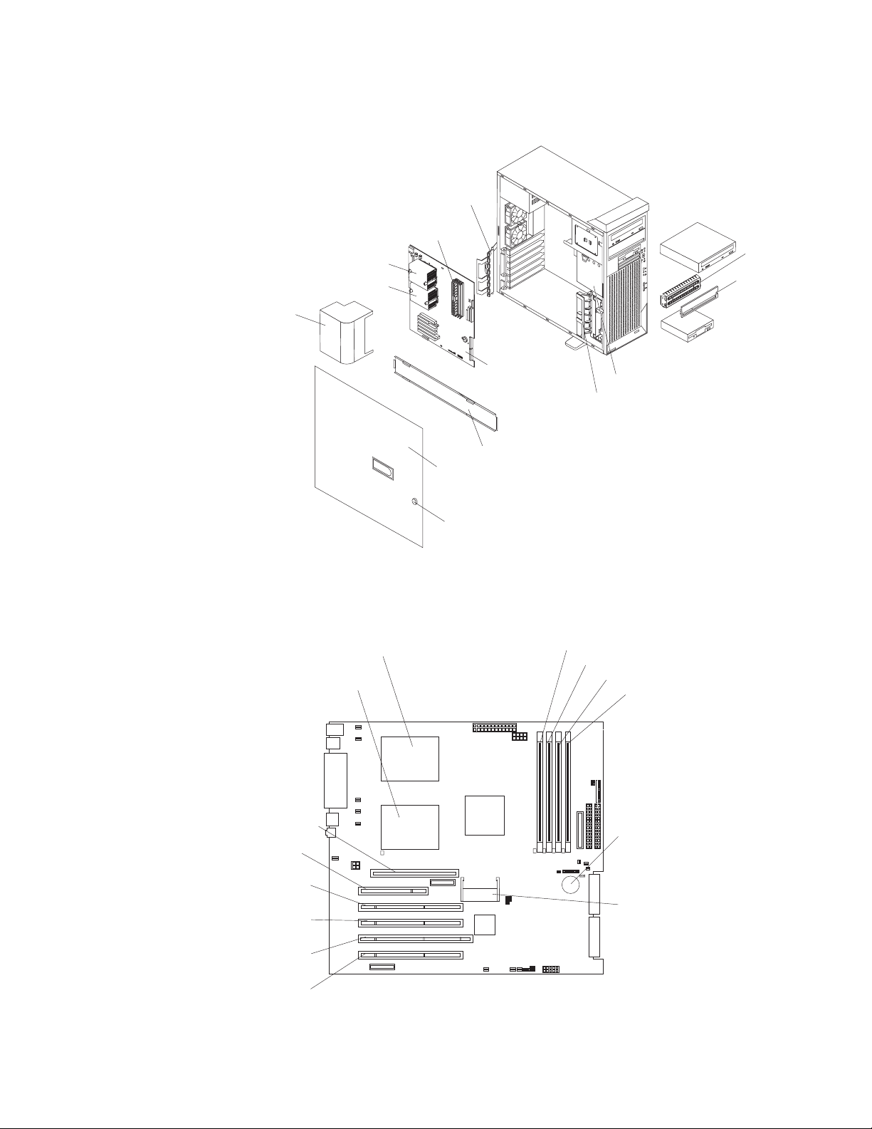
Major components of your computer
The following illustration shows the major components in the computer.
Rear adapterretention bracket
Memory modules
Microprocessor 1
Microprocessor 2
Air baffle
EMC
4
9
3
1
shield
Filler
panel
System-board option connectors
The following illustration shows the system-board connectors for user-installable
options.
Microprocessor 1
(CPU1)
Microprocessor 2
(CPU2)
Support bracket
Side cover
Key lock
System board
Drive cage
Front adapterretention bracket
DIMM 1
DIMM 2
DIMM 3
DIMM 4
AGP Pro slot
PCI slot 1
(PCI1)
PCI-X slot 2
(PCI2)
PCI-X slot 3
(PCI3)
PCI-X slot 4
(PCI4)
PCI-X slot 5
(PCI5)
Battery
IEEE 1394
(FireWire)
adapter
Mini-PCI
type III slot 6
(PCI6)
Chapter 2. Installing the hardware
11
Page 32

v
12
System-board internal connectors
The following illustration shows the internal connectors on the system board.
Rear fan 1
(SYSFAN1)
Ethernet
activity LED
(JFR1)
Rear fan 2
(SYSFAN2)
CD audio
(JCD1)
Main power
(POWER1)
Powe r
(POWER2)
SCSI LED
(J18)
Diskette
drive (FDD1)
Secondary IDE
(IDE2)
Primary IDE
(IDE1)
Error LED
(JER2)
Cover switch
(JCI2)
Internal speaker
(JSPK1)
Front panel
switch/LEDs
(JFP1)
SCSI
channel A
(SCSI1)
SCSI
channel B
(SCSI2)
System-board external connectors
The following illustration shows the external input/output port connectors on the
system board.
Mouse
Keyboard
USB 1/
USB 2
Parallel
(LPT1)
Serial A/
Serial B
(COMA/
COMB)
Ethernet
Audio
Front panel audio (J15)
Front panel USB (JUSB3)
Installation guidelines
Before you begin installing options in your computer, read the following information:
Review the safety information beginning on page v and the guidelines in
“Handling static-sensitive devices” on page 13. These guidelines will help you
work safely with your computer and options.
IBM IntelliStation Z Pro Type 6221: Installation Guide
Page 33

v
v
v
v
v
To
v
v
on
v
v
v Do
v
To
v
v
v Do
v Do
v
v
v
v
Make sure that you have an adequate number of properly grounded electrical
outlets for your computer, monitor, and other devices that you will connect to the
computer.
Back up all important data before you make changes to disk drives.
Have a small flat-blade screwdriver available.
When you need to access the inside of the computer to install options, you might
find it easier to lay the computer on its side.
The blue color on components and labels identifies touch points where you can
grip a component, move a latch, and so on.
For a list of supported options for your computer, go to http://www.ibm.com/pc/;
then, select your country and navigate to the list of options for your computer.
System reliability considerations
help ensure proper system cooling and system reliability, make sure that:
Each of the drive bays has a drive or a filler panel and electromagnetic
compatibility (EMC) shield installed.
There is adequate space around the computer to allow the computer cooling
system to work properly. Leave approximately 50 mm (2 in.) of open space
around the front and rear of the computer. Do not place objects in front of the
fans. For proper cooling and airflow, replace the computer cover before turning
the computer. Operating the computer for extended periods of time (over 30
minutes) with the computer cover removed might damage computer components.
You have followed the cabling instructions that come with optional adapters.
You have replaced a failed fan as soon as possible.
not remove the air baffle when the computer is operational. Operating the
computer without the air baffle might cause the microprocessor to overheat.
Microprocessor socket 2 always contains either a microprocessor baffle or a
microprocessor and heatsink.
Handling static-sensitive devices
Attention:
avoid damage, keep static-sensitive devices in their static-protective packages until
you are ready to install them.
reduce the possibility of electrostatic discharge, observe the following
precautions:
Limit your movement. Movement can cause static electricity to build up around
you.
Handle the device carefully, holding it by its edges or its frame.
not touch solder joints, pins, or exposed circuitry.
not leave the device where others can handle and damage it.
While the device is still in its static-protective package, touch it to an unpainted
metal part of the computer for at least 2 seconds. This drains static electricity
from the package and from your body.
Remove the device from its package and install it directly into the computer
without setting down the device. If it is necessary to set down the device, put it
back into its static-protective package. Do not place the device on your computer
cover or on a metal surface.
Take additional care when handling devices during cold weather. Heating reduces
indoor humidity and increases static electricity.
Static electricity can damage electronic devices and your computer. To
Chapter 2. Installing the hardware
13
Page 34

To
1.
2.
on
3.
14
Removing the side cover
remove the side cover, you might find it easier to lay the computer on its side.
Complete the following steps to remove the side cover of the computer:
Review the “Installation guidelines” on page 12..
Turn off the computer and all attached devices (see “Turning off the computer”
page 36); then, disconnect all power cords and external cables.
Unlock the side cover; then, pull the cover release latch away from the
computer, and push the side cover toward the rear of the computer. Lift the side
cover off the computer and set it aside.
1394
Attention: For proper cooling and airflow, replace the side cover before turning on
the computer. Operating the computer with the cover removed might damage
computer components.
IBM IntelliStation Z Pro Type 6221: Installation Guide
Page 35

1.
2.
on
3.
4.
5.
6.
To
Removing and installing the support bracket
When working with some devices, such as hard disk drives and memory modules,
you must first remove the support bracket to access the device.
Complete the following steps to remove the support bracket:
Review the “Installation guidelines” on page 12..
Turn off the computer and all attached devices (see “Turning off the computer”
page 36); then, disconnect all power cords and external cables.
Remove the side cover (see “Removing the side cover” on page 14).
Pull out on the rear end of the support bracket approximately 150 mm (6 in.).
Disengage the front end of the support bracket from the computer and set the
bracket aside.
4
9
3
1
Continue with the option installation or removal procedure.
reinstall the support bracket, reverse the previous steps.
Chapter 2. Installing the hardware
15
Page 36

v
v
v
be
v
v
v
v
–
–
–
v To
in
v
v
16
Working with adapters
Your computer comes with adapter connectors or slots. The AGP video adapter is
installed in the AGP Pro slot, and some models have an IEEE 1394 (FireWire)
adapter installed in mini-PCI slot 6 (PCI6). You can install up to five additional
optional adapters in your computer in PCI slot 1 (PCI1) and PCI-X slots 2 through 5
(PCI2 through PCI5).
See “System-board option connectors” on page 11 for the locations of expansion
slots on the system board.
Adapter considerations
Before you install an adapter, review the following information:
Read the documentation that comes with your operating system.
Locate the documentation that comes with the adapter and follow those
instructions in addition to the instructions in this chapter. If you need to change
the switch or jumper settings on your adapter, follow the instructions that come
with the adapter.
You can install only a 32-bit adapter in the 32-bit PCI slot 1; 64-bit adapters can
installed only in the 64-bit PCI-X slots 2 through 5.
You can install full-length adapters in all five expansion slots; however, full-length,
double-width adapters will not fit in slot 5 and are not supported. None of the
expansion slots are hot-plug.
The 32-bit PCI slot 1 supports 5.0 V signaling PCI adapters; it does not support
3.3 V signaling adapters or 64-bit adapters.
The 64-bit PCI-X slots 2 through 5 support 3.3 V signaling PCI or PCI-X
adapters; they do not support 5.0 V signaling adapters.
The PCI bus configuration is as follows:
The 32-bit PCI slot 1 and mini-PCI slot 6 (for the IEEE 1394 controller) are on
the 33 MHz PCI bus.
Note: If your computer did not come with a IEEE 1394 (FireWire) adapter
installed in mini-PCI slot 6, do not install an adapter in this slot. It is not
supported.
The 64-bit PCI-X slots 2 and 3 and the integrated Ethernet controller are on
the 100 MHz PCI-X bus, channel A.
The 64-bit PCI-X slots 4 and 5 and the integrated SCSI controller with RAID
capabilities are on the 100 MHz PCI bus, channel B. If an optional
ServeRAID-5i controller is installed, it overrides the standard functionality of
the integrated SCSI controller with RAID capabilities and forces PCI-X slots 4
and 5 to 66 MHz.
The optional ServeRAID-5i controller can be installed only in PCI-X slot 4 and
v
must use the 3-U bracket that comes preinstalled on the controller.
provide failover protection, an optional Ethernet adapter can be installed only
PCI-X slots 2 through 5.
Installing an optional RAID adapter in your computer will require that you reload
the operating system and applications that came pre-installed on your computer.
The system scans the AGP slot, mini-PCI slot 6, PCI expansion slot 1, and PCI-X
expansion slots 2 through 5 to assign system resources. Then, the system starts
the PCI devices in the following order, if you have not changed the default
startup sequence: AGP slot, mini-PCI slot 6, PCI expansion slot 1, system-board
IBM IntelliStation Z Pro Type 6221: Installation Guide
Page 37

v
4 is
1.
2.
on
3.
4.
5.
6.
7.
integrated drive electronics (IDE) or small computer system interface (SCSI)
devices (including optional ServeRAID-5i controller), and then PCI-X expansion
slots 2 through 5.
For a list of supported options for your computer, go to http://www.ibm.com/pc/;
then, select your country and navigate to the list of options for your computer.
Installing an adapter
Note: You can install an optional ServeRAID-5i controller only in PCI-X slot 4. Slot
the only PCI-X slot that supports the ServeRAID-5i controller requirements.
Install the ServeRAID-5i controller using the 3-U bracket that comes preinstalled on
the controller. See the documentation that comes with the ServeRAID-5i controller
for additional information.
Complete the following steps to install an adapter in your computer:
Review the “Installation guidelines” on page 12 and “Handling static-sensitive
devices” on page 13.
Turn off the computer and all attached devices (see “Turning off the computer”
page 36); then, disconnect all power cords and external cables.
Remove the side cover (see “Removing the side cover” on page 14).
Determine which slot you will use for the adapter. Check the instructions that
come with the adapter for any requirements, restrictions, or cabling
instructions. It might be easier to route cables before you install the adapter.
Rotate the rear adapter-retention bracket to the open (unlocked) position and
remove it from the computer. Rotate the front adapter-retention bracket to the
open position. If you are installing a smaller adapter, remove only the rear
adapter-retention bracket.
Remove the expansion-slot cover. From the rear of the computer, press on the
slot cover. Grasp it and pull it out of the expansion slot. Store it in a safe place
for future use.
Note: Expansion-slot covers must be installed on all vacant slots. This
maintains the electronic emissions standards of the computer and ensures
proper ventilation of computer components.
Set any jumpers or switches on the adapter or system board according to the
documentation that comes with the adapter.
Attention: Be certain that the adapter is correctly seated in the expansion
slot before you turn on the computer. Incomplete installation of an adapter
might damage the system board or the adapter.
Chapter 2. Installing the hardware
17
Page 38

9.
If
If
If
18
8.
Remove the adapter from the static-protective package, carefully grasp the
adapter by the top edge or upper corners, and align it with the expansion slot
guides; then, press the adapter firmly into the expansion slot. Move the
adapter directly from the static-protective package to the adapter slot. Avoid
touching the components and gold-edge connectors on the adapter.
4
9
3
Expansion
slot cover
1
Rear
adapterretention
bracket
Adapter
Front
adapterretention
bracket
Connect required cables to the adapter. Route cables so that they do not block
the flow of air from the fans. If you are installing an optional SCSI adapter, see
“Cabling an optional SCSI adapter” on page 19 for additional information.
10.
11.
you have another adapter to install, repeat steps 4 through 9.
you have installed a full-length adapter, rotate the front adapter-support
bracket to the closed (locked) position.
12.
Reinstall the rear adapter-retention bracket; then, rotate the bracket to the
closed (locked) position.
Note: If any adapters in your computer are large or have heavy cables
attached to them, you can remove the rear adapter-retention bracket and
secure all of the adapters with expansion-slot screws. The expansion-slot
screws are stored on the back of the computer next to slot 1.
13.
you have other options to install, do so now; otherwise, go to “Completing
the installation” on page 32.
IBM IntelliStation Z Pro Type 6221: Installation Guide
Page 39

1.
2. An
1.
2.
3.
on
4.
Cabling an optional SCSI adapter
You can install an optional SCSI adapter in your computer to control the internal
hard disk drives. With a SCSI adapter installed you can configure the internal hard
disk drives into disk arrays. You can also cable a SCSI adapter to external hard
disk drives. See your SCSI adapter option documentation for complete instructions
for installing a SCSI adapter in your computer and for additional information about
SCSI adapters.
Notes:
The information in this section does not apply to the ServeRAID-5i controller,
which uses the integrated SCSI controller with RAID capabilities on the system
board.
optional SCSI adapter or cable option is required to connect external SCSI
devices.
Complete the following steps to cable an optional SCSI adapter:
Install the SCSI adapter (see “Installing an adapter” on page 17).
Connect the SCSI-signal cable to the adapter and to one or more of the
signal-cable connectors to the rear of the SCSI devices.
Connect the SCSI-activity-indicator cable to the adapter and to the SCSI-LED
connector (J18) on the system board. See “System-board internal connectors”
page 12 for the location of the SCSI-LED connector.
SCSI
signal
cable
Rear
adapter
retention
bracket
SCSI signal
cable connector
SCSI activity
indicator cable
connector
SCSI
Adapter
SCSI
activity
indicator
cable
Front
adapter
retention
bracket
Complete the installation of the optional SCSI adapter.
4
9
3
1
Chapter 2. Installing the hardware
19
Page 40

v
v
v
1.
2.
3.
4.
5. To
6.
or
7.
20
Installing internal drives
Depending on your computer model, you might have one or more of the following
drives installed:
Diskette
Hard disk
CD-ROM, CD-RW, or DVD/CD-RW combo
Internal drive bays
Your IntelliStation Z Pro computer comes with an IDE CD-ROM, CD-RW, or
DVD/CD-RW combo drive in bay 1, a 3.5-in., 1.44 MB diskette drive in bay 3, and a
hard disk drive installed in bay 4.
Bay 1
Bay 2
Bay 3
Bay 4
4
9
3
1
Bay 5
Bay 6
Notes:
Diskette drives, tape drives, CD-ROM, DVD/CD-RW, and DVD-ROM drives are
examples of removable-media drives. You can install removable-media drives in
bays 1, 2, and 3 only.
The integrated IDE controller in your computer supports the connection of up to
four IDE devices.
You can install a 3.5-in. slim-high or 5.25-in. half-high removable-media drive,
such as a tape backup, CD-RW, or DVD drive, in bay 2.
The IntelliStation Z Pro computer supports only one diskette drive.
install a 3.5-in. drive in a 5.25-in. bay, you must use the 5.25-in. conversion
kit, supplied with the option.
The electromagnetic interference (EMI) integrity and cooling of the computer are
protected by having all bays and PCI slots covered or occupied. When you
install a drive or PCI adapter, save the EMC shield and filler panel from the bay
the PCI adapter slot cover in the event you later remove the option.
For a complete list of supported options for your computer, go to
http://www.ibm.com/pc/; then, select your country and navigate to the list of
options for your computer.
IBM IntelliStation Z Pro Type 6221: Installation Guide
Page 41

1.
2.
3.
4.
1.
2.
on
3.
4.
5.
Preinstallation steps
Some of these steps are required only during the initial installation of an internal
drive.
Review the safety information beginning on page v, “Installation guidelines” on
page 12,, and the documentation that comes with your drive.
Verify that you have all the cables and other equipment specified in the
documentation that comes with the drive.
Choose the bay in which you want to install the drive.
Check the instructions that come with the drive to see if you need to set any
switches or jumpers on the drive. If you are installing a SCSI device, be sure to
set the SCSI ID for that device.
Installing a drive in bay 2
Complete the following steps to install a drive in bay 2:
Follow the instructions in “Preinstallation steps” on page 21.
Turn off the computer and all attached devices (see “Turning off the computer”
page 36); then, disconnect all power cords and external cables.
Remove the side cover (see “Removing the side cover” on page 14).
Remove the support bracket (see “Removing and installing the support
bracket” on page 15).
Use a screwdriver to pry the filler panel and EMC shield away from the
computer.
Note: If you are installing a drive that contains a laser, observe the following
safety precaution.
Chapter 2. Installing the hardware
21
Page 42

or
v Do
v
6.
on a
22
Statement 3:
CAUTION:
When laser products (such as CD-ROMs, DVD drives, fiber optic devices,
transmitters) are installed, note the following:
not remove the covers. Removing the covers of the laser product
could result in exposure to hazardous laser radiation. There are no
serviceable parts inside the device.
Use of controls or adjustments or performance of procedures other
than those specified herein might result in hazardous radiation
exposure.
DANGER
Some
laser products contain an embedded Class 3A or Class 3B laser
diode. Note the following.
Laser radiation when open. Do not stare into the beam, do not view
directly with optical instruments, and avoid direct exposure to the
beam.
EMC shield
Filler panel
4
9
3
1
Touch the static-protective package containing the drive to any unpainted metal
surface on the computer; then, remove the drive from the package and place it
static-protective surface.
IBM IntelliStation Z Pro Type 6221: Installation Guide
Page 43

8. If
9.
of
be
If
1.
2.
on
3.
4.
7.
Set any jumpers or switches on the drive according to the documentation that
comes with the drive.
Note: You might find it easier to install the new drive into the appropriate
opening on the front, and then attach the cables.
you are installing a 5.25-in. drive in bay 2, push the drive into the bay; then,
use the two screws to attach the drive to the drive cage. If you are installing a
3.5-in. drive in bay 2, you must attach the 5.25-in. conversion kit, supplied with
your option, to the 3.5-in. drive.
Determine whether the drive is an IDE or SCSI device; then, connect one end
the appropriate signal cable into the back of the drive and make sure that
the other end of this cable is connected into the appropriate IDE or SCSI
connector on the system board. See “Power and signal cables for internal
drives” on page 25 for additional information about cabling drives and
“System-board internal connectors” on page 12 for the location of IDE and
SCSI connectors on the system board. If there are open connectors on the
cables connecting an existing IDE drive, this cable can be used to connect the
new drive. The 3-connector SCSI cable that comes with your computer cannot
used to connect a SCSI drive in bay 2.
10.
Route the signal cable so that it does not block the air flow to the rear of the
drives, or over the microprocessor and memory.
11.
Connect the power cable to the back of the drive. The connectors are keyed
and can be inserted only one way.
12.
you have other options to install or remove, do so now; otherwise replace
the support bracket and then go to “Completing the installation” on page 32.
Installing a hard disk drive in bay 4, 5, or 6
Bays 4, 5, and 6 are in the drive cage. The drive cage is behind the front of the
adapter-support bracket.
Note: You might find it useful to work with the computer laying on its side.
Complete the following steps to install a drive in bay 4, 5, or 6:
Follow the instructions in “Preinstallation steps” on page 21.
Turn off the computer and all attached devices (see “Turning off the computer”
page 36); then, disconnect all power cords and external cables.
Remove the side cover (see “Removing the side cover” on page 14).
Remove the support bracket (see “Removing and installing the support
bracket” on page 15).
Chapter 2. Installing the hardware
23
Page 44

6.
7.
8.
of
9.
24
5.
Grasp the drive cage and rotate the cage out of the computer until it locks into
place with the drive-cage retention tab and the open ends of the drive slots
and installed drives are facing you. Ensure that the drive cage locks into place
over the drive-cage retention tab by rotating the drive cage all the way out of
the computer.
4
9
3
1
Attach the blue guide rails to the side of the drive using the screws that are
provided.
Slide the drive into the drive cage until the plastic tabs on the drive guide rails
lock into place in the drive cage. Clear any cables that might impede the
replacement of the drive cage.
Determine whether the drive is an IDE or SCSI device; then, connect one end
the appropriate signal cable into the back of the drive and make sure that
the other end of this cable is connected into the appropriate IDE or SCSI
connector on the system board. See “Power and signal cables for internal
drives” on page 25 for additional information about cabling drives and
“System-board internal connectors” on page 12 for the location of IDE and
SCSI connectors on the system board. If there are open connectors on the
cables connecting existing IDE or SCSI drives, these cables can be used to
connect the new drive.
Route the signal cable so that it does not block the air flow to the rear of the
drives or over the microprocessor and memory.
10.
Connect the power cable to the back of the drive. The connectors are keyed
and can be inserted only one way.
IBM IntelliStation Z Pro Type 6221: Installation Guide
Page 45

If
v
v
v
v If
v If
v If
v
At
v
–
11.
Push the drive cage outward, and press in on the drive-cage release tab; then,
rotate the cage back into the computer.
4
9
3
1
12.
you have other options to install or remove, do so now; otherwise replace
the support bracket (see “Removing and installing the support bracket” on
page 15) and then go to “Completing the installation” on page 32.
Power and signal cables for internal drives
Your computer uses cables to connect IDE and SCSI devices to the power supply
and to the system board. (See “System-board internal connectors” on page 12 for
the location of system-board connectors.) Review the following information before
connecting power and signal cables to internal drives:
The drives that are preinstalled in your computer come with power and signal
cables attached. If you replace any drives, remember which cable is attached to
which drive.
When you install a drive, ensure that one of the drive connectors of the signal
cable is connected to the drive and that the connector at the other end of the
signal cable is connected to the system board.
The computer has two IDE buses, primary and secondary. Each of these buses
supports up to two IDE devices. The primary IDE bus uses connector IDE1 on
the system board and the secondary IDE bus uses connector IDE2.
you have only one IDE device on a cable, it must be set as a master device.
two IDE devices are used on a single cable, one must be designated as the
master device and the other as the subordinate device; otherwise, the computer
might not recognize some of the IDE devices. The master and subordinate
designation is determined by switch or jumper settings on each IDE device.
two IDE devices are on a single cable and only one is a hard disk drive, the
hard disk drive must be set as a master device.
The following cables are provided:
Power cables: Four-wire power cables connect the drives to the power supply.
the end of these cables are plastic connectors that can be attached to
different drives; these connectors vary in size.
Signal cables: Signal cables are typically flat cables, also called ribbon cables,
that connect IDE, SCSI, and diskette drives to the system board. Two or three
types of signal cable come with your computer.
IDE: The wider IDE signal cable has three connectors. One of these
connectors is attached to the drive, one is a spare, and the third is attached to
Chapter 2. Installing the hardware
25
Page 46

–
–
1.
2.
of 8 GB of
3.
4.
or
5.
6.
26
the primary or secondary IDE connector on the system board. The spare
connector can be used to connect additional IDE drives to your computer.
The CD-ROM drive is attached to an ATA 100 signal cable. ATA 100 signal
cables are color-coded. The blue connector is attached to the system board.
The black connector is attached to the master IDE device. The gray middle
connector is attached to the subordinate IDE device. If you are installing an
additional hard disk drive, you must change the switch or jumper setting on
the CD-ROM drive to make the drive a subordinate device, set the switch or
jumper setting on the new drive to master, and change the connector used for
the CD-ROM drive to the gray middle connector. The new drive will be
connected to the black master IDE device connector.
Diskette drive: The narrower signal cable has two connectors. One is
attached to the diskette drive, and the other is attached to the connector
(FDD1) on the system board.
SCSI: A round SCSI cable connects SCSI devices to the integrated SCSI
controller with RAID capabilities on the system board. For more information
about connecting SCSI devices, see the SCSI documentation.
Installing memory modules
Adding memory to your computer is an easy way to make programs run faster. You
can increase the amount of memory in your computer by installing memory
modules. Your IntelliStation Z Pro computer uses industry-standard PC2100
double-data-rate (DDR) dual inline memory modules (DIMMs).
Notes:
The system board contains four DIMM connectors and supports two-way
memory interleaving.
The DIMM options available for your computer are 128 MB, 256 MB, 512 MB, 1
GB, and 2 GB. Your computer supports a minimum of 256 MB and a maximum
system memory.
The amount of usable memory will be reduced depending on the system
configuration. A certain amount of memory must be reserved for system
resources. The BIOS will display the total amount of installed memory and the
amount of configured memory.
Your computer comes with two 256 MB or 512 MB DIMMs (for a total of 512 MB
1024 MB) installed in the DIMM 3 and DIMM 4 memory connectors. When
you install additional DIMMs, be sure to install them as a pair in DIMM
connectors 1 and 2.
DIMMs must be installed in matched pairs. The first pair of DIMMs you install in
DIMM 3 and DIMM 4 memory connectors must be the same size, speed, type,
and technology. You can mix compatible DIMMs from various manufacturers. If
you install a second pair of DIMMs in DIMM 1 and DIMM 2 memory connectors,
they do not have to be the same size, speed, type, and technology as the
DIMMs you installed in DIMM 3 and DIMM 4 memory connectors. However, the
size, speed, type, and technology of the DIMMs you install in DIMM 1 and
DIMM 2 memory connectors must match each other.
Install only 133 MHz (memory bus), 2.5 V, 184-pin, double-data-rate (DDR),
PC2100, registered synchronous dynamic random-access memory (SDRAM)
with error correcting code (ECC) DIMMs. These DIMMs must be compatible
with the latest PC2100 SDRAM Registered DIMM specification. For a list of
supported options for your computer, go to http://www.ibm.com/pc/; then, select
your country and navigate to the list of options for your computer.
IBM IntelliStation Z Pro Type 6221: Installation Guide
Page 47

1.
2.
on
3.
4.
5.
6.
7.
8.
9.
so
7.
Your computer supports Chipkill
™
memory if the DIMMs are all type x4 and are
256 MB or larger. Using any 128 MB DIMMs or DIMMs that are not type x4 on
your computer disables Chipkill memory.
Complete the following steps to install a DIMM:
Review the safety information beginning on page v, “Installation guidelines” on
page 12,, and “Handling static-sensitive devices” on page 13.
Turn off the computer and all attached devices (see “Turning off the computer”
page 36); then, disconnect all power cords and external cables.
Remove the side cover (see “Removing the side cover” on page 14).
Remove the support bracket (see “Removing and installing the support
bracket” on page 15).
You might find it easier to install memory modules if you rotate the drive cage
out of the computer. Grasp the drive cage and rotate until it locks into place.
See the illustration on page 24 for additional information.
Locate the DIMM connectors on the system board. Determine the connectors
into which you will install the DIMMs. Install the DIMMs in the order shown in
the following table.
Table 2. DIMM installation sequence
Installation order
First
Second
DIMM connectors
DIMM 3 and DIMM 4
DIMM 1 and DIMM 2
Diagnostic reference
Bank 2
Bank 1
Open the retaining clips and, if necessary, remove any existing DIMM.
Touch the static-protective package containing the DIMM to any unpainted
metal surface on the computer. Then remove the new DIMM from the package.
Gently open the retaining clip on each end of the DIMM slot. Turn the DIMM
that the pins align correctly with the connector.
Chapter 2. Installing the hardware
27
Page 48

If
28
10.
Insert the DIMM into the connector. Firmly press the DIMM straight down into
the connector by applying pressure on both ends of the DIMM simultaneously.
The retaining clips snap into the locked position when the DIMM is firmly
seated in the connector. If there is a gap between the DIMM and the retaining
clips, the DIMM has not been correctly installed. Open the retaining clips,
remove the DIMM, then reinsert it.
DIMM 1
DIMM 2
DIMM 3
DIMM 4
11.
you have other options to install or remove, do so now; otherwise rotate the
cage back into the computer, replace the support bracket (see “Removing and
installing the support bracket” on page 15), and go to “Completing the
installation” on page 32.
IBM IntelliStation Z Pro Type 6221: Installation Guide
Page 49

v
v
be
to
A
1. To
2.
3.
4. If
5.
an
Installing an additional microprocessor
Your computer comes with one microprocessor installed on the system board. Your
computer supports up to two microprocessors. With two microprocessors, your
computer can operate as a symmetric multiprocessing (SMP) computer. With SMP,
certain operating systems and application programs can distribute the processing
load among the microprocessors.
Before you begin:
Thoroughly review the documentation that comes with the microprocessor to
determine the required BIOS update. The latest level of BIOS code for your
computer is available through the World Wide Web. See the User’s Guide on the
IBM IntelliStation Documentation CD for the World Wide Web addresses.
(Optional) Obtain an SMP-capable operating system. For a list of supported
operating systems and other options for your computer, go to
http://www.ibm.com/pc/; then, select your country and navigate to the list of
options for your computer.
Attention: To ensure proper computer operation when you install an additional
microprocessor, use microprocessors that have the same cache size and type, and
the same clock speed. Microprocessor internal and external clock frequencies must
identical. You can use the Configuration/Setup Utility program in your computer
determine the specific type of microprocessor on your system board.
Important:
microprocessor must always be installed in socket CPU1 of the
system board.
Notes:
order additional microprocessor options, contact your IBM marketing
representative or authorized reseller.
Terminator cards are not required for empty microprocessor sockets. However,
for airflow, an empty microprocessor socket must contain a microprocessor
baffle.
The microprocessor speeds are automatically set for this computer; therefore,
you do not need to set any microprocessor frequency-selection jumpers or
switches.
you need to replace a microprocessor, call for service.
For additional illustrations of the system-board components, see “System-board
option connectors” on page 11..
The Microsoft Windows XP operating system that comes preinstalled on your
computer automatically configures itself when an additional microprocessor is
installed. Other operating systems might need to be manually configured to support
additional microprocessor. See the User’s Guide on the IBM IntelliStation
Documentation CD for instructions.
Chapter 2. Installing the hardware
29
Page 50

1.
2.
on
3.
4.
5.
6.
7.
8. If
9.
a.
b.
30
Complete the following steps to install an additional microprocessor.
Microprocessor
baffle
Microprocessor
release lever
DIMMs
Microprocessor 2
Heatsink 2
Captive screws
Review the “Installation guidelines” on page 12 and “Handling static-sensitive
devices” on page 13.
Turn off the computer and all attached devices (see “Turning off the computer”
page 36); then, disconnect all power cords and external cables.
Remove the side cover (see “Removing the side cover” on page 14).
Remove the support bracket (“Removing and installing the support bracket” on
page 15).
Remove the air baffle by unhooking it from its retaining tabs and lifting it off the
chassis.
Locate the second microprocessor socket (connector CPU2) on the system
board.
Remove the microprocessor baffle from the second microprocessor socket.
the second microprocessor socket is covered with protective film, peel and
remove the film.
Install the microprocessor:
Touch the static-protective package containing the new microprocessor to
any unpainted metal surface on the computer; then, remove the
microprocessor from the package.
Rotate the locking lever on the microprocessor socket from its closed and
locked position until it stops or clicks in the fully open position
(approximately 135° angle).
Attention: You must ensure that the locking lever on the microprocessor
socket is in the fully open position before you insert the microprocessor in
the socket. Failure to do so might result in permanent damage to the
microprocessor, microprocessor socket, and system board.
IBM IntelliStation Z Pro Type 6221: Installation Guide
Page 51

of
1) Do
2)
d.
a.
b.
c.
If
c.
Center the microprocessor over the microprocessor socket. Align the
triangle on the corner of the microprocessor with the triangle on the corner
the socket and carefully press the microprocessor into the socket.
Attention:
not use excessive force when pressing the microprocessor into the
socket.
Make sure that the microprocessor is oriented and aligned correctly
with pin number 1 in the socket before you try to close the lever. The
following illustration shows the alignment marks for both
microprocessors and sockets.
Alignment marks
Microprocessor 1
Microprocessor 2
Alignment marks
Microprocessor
Microprocessor
socket 1
socket 2
Carefully close the lever to secure the microprocessor in the socket.
Install the heat sink on the microprocessor.
10.
Thermal grease
Heat sink
Remove the plastic cover from the bottom of the heat sink.
Attention: Do not set the heat sink down after you remove the plastic
cover and do not touch the thermal grease on the bottom of the heat sink.
Touching the thermal grease will contaminate it. If the thermal grease on
the microprocessor or heat sink becomes contaminated, contact your
service technician.
Align and place the heat sink on top of the microprocessor, grease side
down, in the retention bracket. Press firmly on the heat sink.
Attention: Alternate the tightening of the two captive screws to prevent
damage to the microprocessor. Ensure that the screws are completely
tightened (until they stop); otherwise, damage to the microprocessor will
occur.
Secure the heat sink to the microprocessor by tightening the captive
screws. Alternate between the two captive screws in the heat sink while
tightening them.
Install the air baffle.
11.
12.
you have other options to install or remove, do so now; otherwise, replace
the support bracket and go to “Completing the installation” on page 32.
Chapter 2. Installing the hardware
31
Page 52

To
1.
on
2.
3.
4.
5.
6. If
To
32
Installing a security rope clip
help prevent theft, you can add a security rope clip and cable to your computer.
Complete the following steps to install a rope clip:
Turn off the computer and all attached devices (see “Turning off the computer”
page 36); then, disconnect all power cords and external cables.
Remove the side cover (see “Removing the side cover” on page 14).
Use a screwdriver to remove the two metal knockouts.
Insert the rope clip through the rear panel; then, attach and tighten the nuts.
Thread a cable through the rope clip and around an object that is not part of or
permanently secured to the building structure or foundation and from which the
cable cannot be removed. Fasten the cable ends together with a lock. After you
add the security cable, be certain it does not interfere with other cables
connected to the computer.
Rope clip
you have other options to install or remove, do so now; otherwise, go to
“Completing the installation.”
Completing the installation
complete your installation, you must reinstall the side cover, connect all the
cables and, for certain options, run the Configuration/Setup Utility program. Follow
the instructions in this section.
IBM IntelliStation Z Pro Type 6221: Installation Guide
Page 53
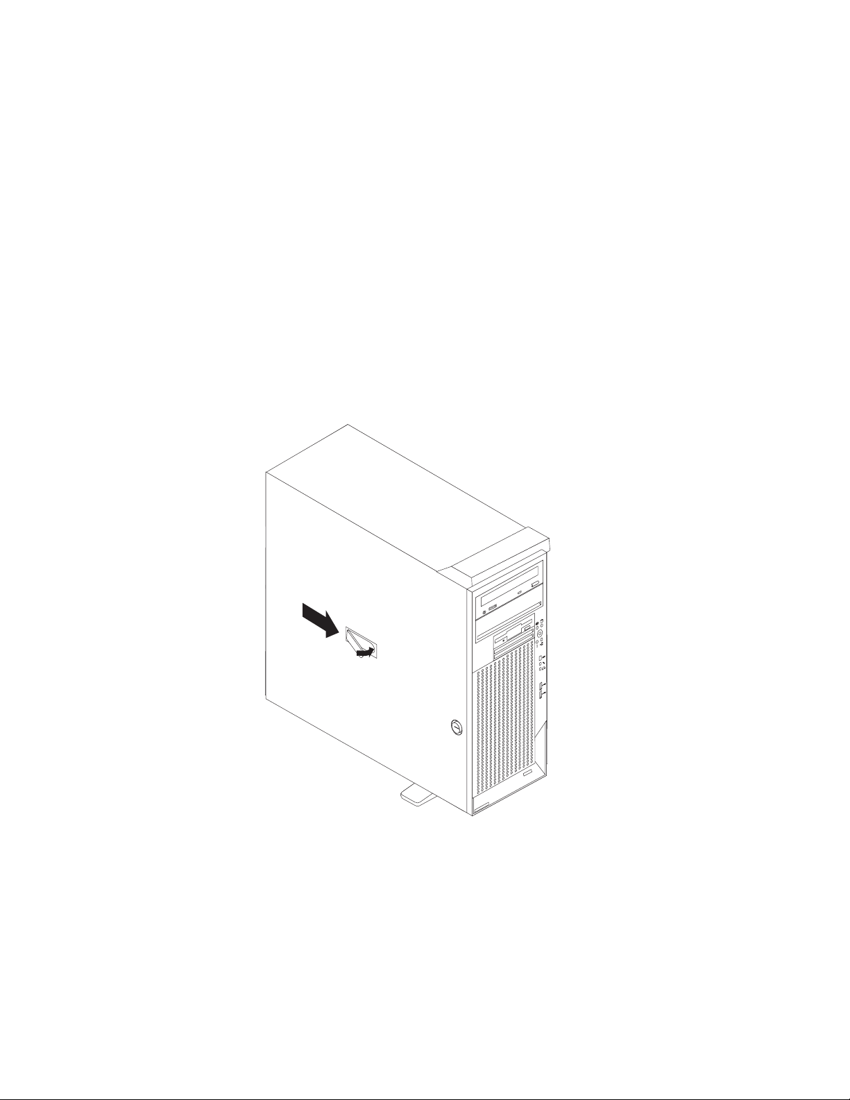
If
1.
2.
3.
4.
Replacing the side cover
you removed the support bracket, reinstall it before you replace the side cover.
See “Removing and installing the support bracket” on page 15.
Note: The rear adapter retaining bracket rests against the computer side cover.
You might find it easier to lay the computer on its side to replace the side cover.
Complete the following steps to replace the side cover:
Before installing the cover, check that all cables, adapters, and other
components are installed and seated correctly and that you have not left loose
tools or parts inside the computer.
Place the bottom lip of the side cover over the bottom edge of the computer
chassis.
Rotate the side cover to a vertical position, inserting the tabs at the top of the
side cover into the matching slots in the computer chassis.
Slide the side cover forward until it locks in place. Press down on the
cover-release-latch button as you close the cover-release latch to lock the side
cover.
4
9
3
1
Chapter 2. Installing the hardware
33
Page 54

If
1.
2.
3.
34
Cabling the computer
your computer cables and connector panel have color-coded connections, match
the color of the cable end with the color of the connector. For example, match a
blue cable end with a blue panel connector, a red cable end with a red connector,
and so on.
Attention: To prevent damage to equipment, the power cord should be connected
last.
The following illustration shows the input/output (I/O) connectors on the rear of the
computer.
Power cord
connector
Mouse
Keyboard
USB 2
USB 1
Serial 1
Parallel
Serial 2
Ethernet
Line out (green)
Line in (blue)
Mic (pink)
IEEE 1394
(FireWire)
Video
2
1
1
2
SCSI knockout
Depending on the video adapter installed in your computer and the monitor you
want to use, you might need to use special video cables that convert signals or
provide an additional connection point for dual-monitor operation. See the User’s
Guide on the IBM IntelliStation Documentation CD or the documentation that comes
with your monitor for additional information.
Turning on the computer
When the computer is connected to an ac power source but is not turned on, the
operating system does not run, and all core logic is shut down; however, the
computer can respond to remote requests to turn on the computer. The power-on
LED flashes to indicate that the computer is connected to an ac power source but is
not turned on (standby mode).
Notes:
Turn on all external devices, such as the monitor, before turning on the
computer.
The power-on LED on the front of the computer is lit when the computer is on
and while it is powering-up.
You can install a circular disk over the power-control button to prevent
accidental manual power-off. This disk, known as the power-control button
shield, comes with your computer.
IBM IntelliStation Z Pro Type 6221: Installation Guide
Page 55

be
v If a
v
v If
If
in
1.
2.
3.
4.
v
v
v
Approximately 20 seconds after the computer is connected to ac power, the
power-control button becomes active, and you can turn on the computer and start
the operating system by pressing the power-control button. The computer can also
turned on in any of the following ways:
power failure occurs while the computer is turned on, the computer will
restart automatically when power is restored.
When you plug in your computer for the first time, Wake on LAN
computer.
your computer was previously turned on, it must be properly turned off for the
Wake on LAN feature to turn on the computer.
Running the operating system setup program
you are starting your computer for the first time, the setup program runs
automatically when you start the computer. The program will prompt you to make
choices or type information. If you need more detailed information than is provided
this Installation Guide, see your operating-system documentation.
Important:
After turning on your computer for the first time, you must complete the
operating system setup procedure before turning off your computer; otherwise,
unexpected results might occur.
The setup program might be slightly different from the one described in your
operating-system manual. Some choices do not appear because they are
preset.
During the setup procedure, you must indicate that you accept the license
agreement.
For Windows operating systems, the registration information will already be
displayed in the registration field. If the Product ID number is not already
displayed, you must type it. The Product ID is on a label attached to the
computer.
®
can turn on the
You will need the following information to complete the setup program in Windows
operating systems:
The documentation that comes with your computer.
Network information from your network administrator, if your computer is being
connected to a network.
The printer model and port, if a printer is attached directly to your computer.
After the setup procedure finishes and the computer restarts, the desktop opens.
Your computer is ready for use.
Chapter 2. Installing the hardware
35
Page 56

v
an
To
→
To
→
→
v
v
v
36
Turning off the computer
When you turn off the computer and leave it connected to ac power, the computer
can respond to remote requests to turn on the computer. To remove all power from
the computer, you must disconnect it from the power source.
Some operating systems require an orderly shutdown before you turn off the
computer. See your operating-system documentation for information about shutting
down the operating system.
Statement 5:
CAUTION:
The power control button on the device and the power switch on the power
supply do not turn off the electrical current supplied to the device. The device
also might have more than one power cord. To remove all electrical current
from the device, ensure that all power cords are disconnected from the power
source.
2
1
The computer can be turned off in any of the following ways:
You can turn off your computer from the operating system. If this feature is
supported by your operating system, it will turn off the computer after performing
orderly shutdown of the operating system.
turn off the computer from the Microsoft Windows XP operating system, click
start
Turn Off Computer; then, select Turn Off.
turn off the computer from the Red Hat Linux operating system, click Red Hat
Linux Main Menu Button
Logout
Shutdown; then, click OK.
You can press the power-control button on the front of the computer. If this
feature is supported by your operating system, it will turn off the computer after
performing an orderly shutdown of the operating system.
Note: After turning off the computer, wait at least 5 seconds before you press
the power-control button to turn on the computer again.
You can press and hold the power-control button for more than 4 seconds to
cause an immediate shutdown of the computer. You can use this feature to turn
off the computer if the operating system stops functioning.
The computer can turn itself off as an automatic response to a critical system
failure.
IBM IntelliStation Z Pro Type 6221: Installation Guide
Page 57

1.
2.
3.
4.
v
v
v On
1.
→
2.
do
3.
©
Chapter 3. Installing software
This chapter describes how to install and configure software for your IBM
IntelliStation Z Pro Type 6221 computer.
Viewing the license agreement
The IBM International License Agreement for Non-Warranted Programs is viewable
through Access IBM. Use of your computer signifies acceptance of this agreement.
Complete the following steps to view the license agreement in Windows XP:
Double-click the Access IBM icon.
Click How do I....
Click Solve problems.
Click IBM International License Agreement.
For Red Hat Linux, when you start your computer, the License Agreement window
opens. To accept the terms of the agreement, click I Agree. You can also view the
license agreement by clicking on the IBM License Agreement icon on your
desktop.
Using Access IBM
Access IBM is an interface through which you can quickly access information or
perform specific tasks.
The choices available from the Access IBM Welcome window are:
How do I...
Select this choice to display information about tasks that are typically performed
immediately after you install a new computer, such as personalizing your
computer to fit your needs, protecting your data, using recovery tools, upgrading
your computer hardware, purchasing IBM services, purchasing IBM options,
solving problems, and viewing the IBM International License Agreement for
Non-Warranted Programs.
Tools & Tips
Select this choice to display information about Access Support, AntiVirus tools,
data backup and restore tools, configuration backup and restoration tools,
diagnostic programs, data migration tools, help, online books, system information
and personalization, and updates.
Select this choice to display information about obtaining additional information
and support on the World Wide Web.
the Web
Copyright IBM Corp. 2004
Complete the following steps to use Access IBM:
Double-click the Access IBM icon on the Windows desktop. If the Access IBM
icon is not available on your desktop, click start → All Programs → IBM
Information
Access IBM.
Click one of the tabs on the Access IBM Welcome window (for example, How
I...).
Click a topic.
37
Page 58

v
v
v
v
v
v
v
v
v
1.
2.
3.
v
v
v
38
Using the built-in configuration programs
The following configuration programs are provided with your computer:
Configuration/Setup Utility
This program is part of the basic input/output system (BIOS) code that comes
with your computer. You can use this program to configure serial- and
parallel-connector assignments, change the drive startup sequence, set the date
and time, and set passwords. For more information about how to start this utility,
see “Starting the Configuration/Setup Utility program.”
LSI Logic Configuration Utility
With the built-in LSI Logic Configuration Utility program, you can configure the
integrated SCSI controller and the devices that are attached to it. For information
about how to start this utility, see “Starting the LSI Logic Configuration Utility
program.”
ServeRAID Manager
The ServeRAID
ServeRAID controller installed, you must use the ServeRAID Configuration
program to define and configure your disk-array subsystem before you install
your operating system. See “Using ServeRAID Manager” on page 39 for more
information.
™
programs come with your computer. If your computer has a
Note:
See the User’s Guide on the IBM IntelliStation Documentation CD for
detailed instructions for using the configuration programs.
Starting the Configuration/Setup Utility program
Configuration/Setup is a menu-driven utility that is part of the BIOS code that comes
with your computer. You can use it to:
Configure serial connector assignments
Change the drive startup sequence
Enable USB keyboard and mouse support
Resolve configuration conflicts
Set the date and time
Set passwords
Complete the following steps to start the Configuration/Setup Utility program:
Turn on the computer and watch the monitor screen.
When the message Press F1 for Configuration/Setup appears, press the F1
key.
Follow the instructions that appear on the screen.
Starting the LSI Logic Configuration Utility program
LSI Logic Configuration Utility is a built-in, menu-driven configuration program that
you can use to:
Perform a low-level format of a SCSI hard disk drive
Set a SCSI device scan order
Set a SCSI ID for a controller
IBM IntelliStation Z Pro Type 6221: Installation Guide
Page 59

1.
2. If
1.
2.
to
3.
4.
v
v
v
v
v
v As an
to
The following section provides the instructions needed to start the LSI Logic
Configuration Utility program. See the User’s Guide on the IBM IntelliStation
Documentation CD for more detailed information about the LSI Logic Configuration
Utility.
Notes:
The integrated SCSI controller with RAID capabilities in your computer supports
redundant array of independent disks (RAID). You can use the LSI Logic
Configuration Utility program built into your computer to configure RAID level 1
for a single pair of attached devices.
your computer has a RAID adapter installed, use the configuration method
supplied with the RAID adapter to view or change SCSI settings for attached
devices.
Complete the following steps to start the LSI Logic Configuration utility program:
Turn on the computer.
When the <<< Press <CTRL><C> to start LSI Logic Configuration Utility
>>> prompt appears, press Ctrl+C.
Note: If an administrator password has been set, a prompt appears asking you
type the password to start the LSI Logic Configuration Utility program.
Use the arrow keys to select a choice (channel) from the screen, then press
Enter.
Follow the instructions on the resulting screen to change the settings of the
selected items; then, press Enter. The Device Properties and Mirroring
Properties choices produce additional screens of parameters to review or
change.
Using ServeRAID Manager
You can use the ServeRAID Manager program, provided on the IBM ServeRAID
Support CD, to:
Configure a redundant array of independent disks (RAID)
Restore a SCSI hard disk to factory-default settings, erasing all data
View your RAID configuration and associated devices
Monitor operation of your RAID controllers
The ServeRAID Manager program operates in two ways:
Startable-CD mode
installed software program
following sections provide instructions for running ServeRAID Manager in
The
startable-CD mode to configure your integrated SCSI controller with RAID
capabilities and perform an initial RAID configuration on your computer. See the
ServeRAID documentation on the IBM ServeRAID Support CD for additional
information about RAID technology and instructions for using ServeRAID Manager
configure your integrated SCSI controller with RAID capabilities.
Chapter 3. Installing software
39
Page 60

1.
2.
1.
2. If
1.
2. To
in
To
40
Attention:
When setting up RAID mirroring, you must set the hard disk drive containing the
operating system as the primary drive. Failure to do so will erase the operating
system and applications that came pre-installed on your computer.
Installing an optional RAID adapter in your computer will require that you reload
the operating system and applications.
Notes:
The integrated SCSI controller with RAID capabilities in your computer supports
only RAID level 1. Installing an optional ServeRAID-5i controller provides
additional RAID levels.
you install a different type of RAID adapter in your computer, use the
configuration method supplied with the RAID adapter to view or change SCSI
settings for attached devices.
Before you install your operating system, you must configure the controller that is
attached to the hard disk drives. You must use the configuration program on the
IBM ServeRAID Support CD to configure the integrated SCSI controller with RAID
capabilities or to configure an optional IBM ServeRAID controller.
Notes:
You cannot use the ServerGuide
™
Setup and Installation CD to configure the
optional controllers.
update the firmware and BIOS for an optional ServeRAID controller, you
must use the IBM ServeRAID Support CD that comes with the ServeRAID
option.
Using ServeRAID Manager in startable-CD mode
The information in this section focuses on using the ServeRAID Manager program
Startable CD mode to configure your controller. For information about installing
ServeRAID Manager, see the documentation on the IBM ServeRAID Support CD.
When you run the ServeRAID Manager program from the startable IBM ServeRAID
Support CD, you are using startable-CD mode, in which you can configure your
controller before you install your operating system.
run the ServeRAID Manager program in startable-CD mode, turn on the
computer; then, insert the IBM ServeRAID Support CD into the CD-ROM drive. If
the ServeRAID Manager program detects an unconfigured controller and ready
drives, the program automatically starts the Configuration wizard, and a window
similar to that shown in Figure 1 on page 41 opens.
IBM IntelliStation Z Pro Type 6221: Installation Guide
Page 61

1. In
2.
3.
4.
To
Figure 1. “Configuration wizard” window
Configuring the controller:
You can use the Configuration wizard to configure
your controller. The Configuration wizard provides two configuration options:
Express and Custom. Express configuration automatically configures your controller,
and you can use Custom configuration to configure your controller manually.
Note: If the integrated RAID controller has two channels, it will appear in the
ServeRAID Manager tree as two controller objects. However, you can configure
only one array and one RAID level-1 logical drive.
Using Express configuration:
Express configuration automatically configures your
controller. It creates an array by grouping together the first two physical drives that
appear in the ServeRAID Manager tree, and it creates a RAID level-1 logical drive.
Complete the following steps to use Express configuration:
the ServeRAID Manager tree, click the controller.
Click Express configuration.
Click Next. The “Configuration summary” window opens.
Review the information that is displayed in the “Configuration summary” window.
change the configuration, click Modify arrays.
Chapter 3. Installing software
41
Page 62
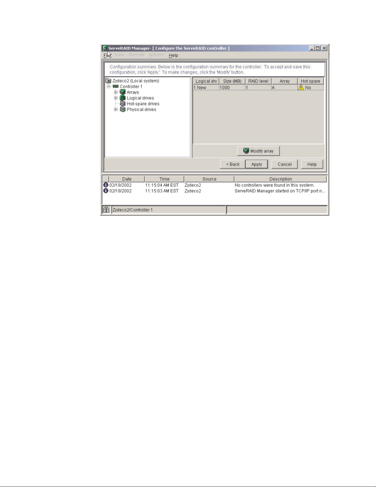
6.
7.
42
Figure 2. “Configuration summary” window
5.
Click Apply; then, click Yes when asked if you want to apply the new
configuration. The configuration is saved in the controller and in the physical
drives.
Exit from the ServeRAID Manager program and remove the CD from the
CD-ROM drive.
Restart the computer.
IBM IntelliStation Z Pro Type 6221: Installation Guide
Page 63
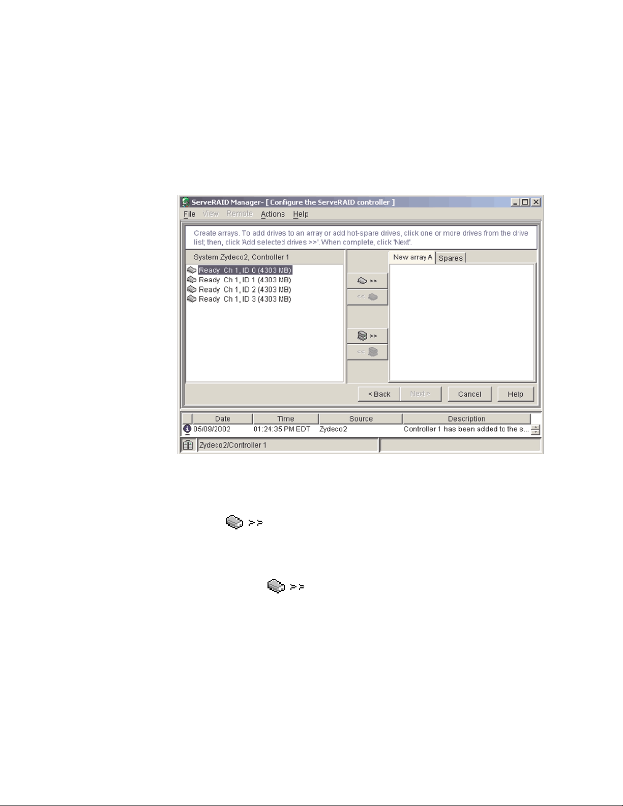
To
1. In
2.
3.
4.
5.
6.
a.
b.
Using Custom configuration:
configure your controller manually, select Custom
configuration. Using Custom configuration, you can select which two physical drives
you want to configure and create a hot-spare drive.
Complete the following steps to use Custom configuration:
the ServeRAID Manager tree, click the controller.
Click Custom configuration.
Click Next. The “Create arrays” window opens.
Figure 3. “Create arrays” window
From the list of ready drives, select the two drives you want to move to the
array.
Click
(Add selected drives) to add the drives to the array.
Complete the following steps if you want to configure a hot-spare drive:
Click the Spares tab.
Select the physical drive you want to designate as the hot-spare drive;
then, click
(Add selected drives).
Chapter 3. Installing software
43
Page 64

8.
9.
44
7.
Click Next. The “Configuration summary” window opens.
Figure 4. “Configuration summary” window
Review the information that is displayed in the “Configuration summary”
window. To change the configuration, click Back.
Click Apply; then, click Yes when asked if you want to apply the new
configuration. The configuration is saved in the controller and in the physical
drives.
10.
Exit from the ServeRAID Manager program, and remove the CD from the
CD-ROM drive.
11.
Restart the computer.
IBM IntelliStation Z Pro Type 6221: Installation Guide
Page 65

To
To
Viewing your configuration
You can use ServeRAID Manager to view information about RAID controllers and
the RAID subsystem (such as arrays, logical drives, hot-spare drives, and physical
drives).
view information, expand the ServeRAID Manager tree; then, click the relevant
tree object. Detailed information about the selected device appears in the right
pane.
Figure 5. ServeRAID Manager window
display available actions for an item, click the item in the ServeRAID Manager
tree and click Actions.
Chapter 3. Installing software
45
Page 66

To
of
46
Getting assistance
For more information about ServeRAID Manager, see the online help system. To
start the help system, either click
(Information about this window) on the
toolbar or select an item from the Help menu.
Figure 6. ServeRAID Manager help menu
The help system (ServeRAID Assist) will open within the ServeRAID Manager
interface.
learn more about the ServeRAID Manager tree objects and the actions that
apply to them, select a tree object and click Actions → Hints and tips. ServeRAID
Assist will start, and information about the tree object will appear in the right pane
ServeRAID Manager.
IBM IntelliStation Z Pro Type 6221: Installation Guide
Page 67

Figure 7. Hints and tips feature
Chapter 3. Installing software
47
Page 68

48
IBM IntelliStation Z Pro Type 6221: Installation Guide
Page 69

v
v
1.
2.
3.
4.
5.
©
Chapter 4. Completing the installation
This chapter contains information to help you register your computer, record
important information in case of emergency, and prepare emergency utilities.
Recording important numbers
Locate the serial, model, and type numbers. Record this information in the following
table. You will need these numbers when communicating with IBM about your
computer.
Record your product information in this table.
Product name
Machine type
Model number
Serial number
Key serial number
Key manufacturer
Key phone number
IBM IntelliStation Z Pro
_____________________________________________
_____________________________________________
_____________________________________________
_____________________________________________
_____________________________________________
_____________________________________________
Registering your computer
Registering your computer helps IBM provide better service to you. When IBM
receives your registration information, it is placed into a central technical support
database. If you need technical assistance, the technical-support representative will
have information about your computer. In addition, comments about your computer
are reviewed by a team dedicated to customer satisfaction and are taken into
consideration in making improvements to IBM computers.
Use one of the following methods to register your computer in Windows:
From the Windows XP desktop, click start → All Programs → IBM Registration
and then follow the instructions.
Register your computer through Access IBM:
Click start.
Click Access IBM.
Click How do I....
Click Get started.
Click Registering your IBM Computer, and then follow the instructions on
the screen.
Register your computer at http://www.ibm.com/pc/register/.
v
Note: If you do not have access to the Internet, you can use the registration
program that starts through Access IBM or the IBM Registration folder to print
your registration information and provide IBM with a mailing address for future
technical assistance.
Copyright IBM Corp. 2004
Red Hat Linux, click the Register PC icon on the desktop to register your
For
computer on the World Wide Web.
49
Page 70

At
on
1.
2.
3.
4.
1.
2.
3.
4.
50
Creating an emergency recovery-repair diskette in Windows
your earliest opportunity, create a recovery-repair diskette and an IBM Enhanced
Diagnostics diskette, and store them in a safe place. In the unlikely event that your
computer becomes unusable, you can use the recovery-repair diskette to access
the Product Recovery program. Additional information about the diskette is in
Access IBM. For more information about using this diskette, see the User’s Guide
the IBM IntelliStation Documentation CD.
Complete the following steps to create a recovery-repair diskette:
From Access IBM, click the How do I... tab; then, click Protect data.
Click Creating emergency diskettes.
Click Recovery Repair diskette.
Follow the instructions on the screen.
Creating an IBM Enhanced Diagnostics diskette in Windows
The IBM Enhanced Diagnostics diskette is a self-starting diagnostic diskette used to
test hardware components on your computer.
Complete the following steps to create the IBM Enhanced Diagnostics diskette:
From the Access IBM, select the How do I... tab; then, click Protect data.
Click Creating emergency diskettes.
Click Diagnostic diskette.
Follow the instructions on the screen.
You can also download the diagnostic program image from the IBM Web site, at
http://www.ibm.com/pc/support, or use the Device Drivers and IBM Enhanced
Diagnostics CD. For more information, see the User’s Guide on the IBM
IntelliStation Documentation CD.
IBM IntelliStation Z Pro Type 6221: Installation Guide
Page 71

If
v
v
v
v
An
by
©
Chapter 5. Solving problems
This section provides basic troubleshooting information to help you resolve some
common problems that might occur with your computer.
you cannot locate and correct the problem using the information in this section,
see Appendix A, “Getting help and technical assistance,” on page 59 and “Solving
problems” in the User’s Guide on the IBM IntelliStation Documentation CD.
Diagnostic tools overview
The following tools are available to help you identify and resolve hardware-related
problems:
POST beep codes and error messages
The power-on self-test (POST) indicates the detection of a problem. See
“Power-on self-test (POST)” on page 52 and “POST error messages” on page 52
for information.
Diagnostic programs and error messages
The diagnostic programs are provided on the Device Drivers and IBM Enhanced
Diagnostics CD. These programs test the major components of your computer.
Note: See “Solving problems” in the User’s Guide on the IBM IntelliStation
Documentation CD for information about the diagnostic programs.
Troubleshooting charts
These charts list problem symptoms and steps to correct the problems. See the
“Troubleshooting charts” on page 53 for information.
System-board error LEDs
LED on the system board might also be lit to help isolate an error indicated
the system error LED on the front of the computer. See the “System-board
error LEDs” on page 57 for more information.
Copyright IBM Corp. 2004
51
Page 72

If
If
1. If
2. A
to
No
No
52
Power-on self-test (POST)
When you turn on the computer, the power-on self-test (POST) performs a series of
tests to check the operation of system components and some of the installed
options.
POST finishes without detecting any problems, the first window of your operating
system or application program appears.
POST detects a problem, more than one beep might sound, an error message
might appear on your screen, or both.
Notes:
you have a user password set, you must type the password and press Enter,
when prompted, before the operating system will load.
single problem might cause several error messages. When this occurs, work
correct the cause of the first error message. After you correct the cause of
the first error message, the other error messages typically will resolve the next
time you run the test.
POST beep codes
The possible types of beep codes are:
beeps
without finding any errors.
Continuous beep
Your startup (boot) microprocessor has failed, or your system board or
speaker subsystem might contain a failing component. If the system
continues through POST with no errors, call for service. If no video appears,
the startup processor has failed.
Beep codes for specific failures
Beep codes indicating specific system problems are listed in the User’s
Guide on the IBM IntelliStation Documentation CD.
POST error messages
The following table provides an abbreviated list of the error messages that might
appear during POST.
Note: See the User’s Guide on the IBM IntelliStation Documentation CD for more
information about the POST error messages.
POST
message
162
163
164
201
beep codes indicates that your computer successfully completed POST
Failing device or
problem found
Change in device
configuration
Time of day has not
been set
Change in memory
configuration
Memory error
Suggested action
Verify that your optional devices are turned on and
installed correctly.
Set the correct date and time.
Verify that your memory is installed properly; then,
restart the computer and run the
Configuration/Setup Utility program.
Verify that your memory is fully seated and installed
properly.
IBM IntelliStation Z Pro Type 6221: Installation Guide
Page 73

a
1.
2. If
v
is
v
v
CD is
If
If
POST
message
289
Failing device or
problem found
Failing DIMM was
disabled
301 and
303
11xx
1162
Keyboard and keyboard
controller
Serial port error
Serial port configuration
error
1601
BIOS code update
needed
1800
PCI adapter hardware
interrupt
2400 and
2462
Video adapter and
memory
00180xxx A PCI adapter requested
resource that is not
available
012980xx
Data for microprocessor Download and install the latest level of system BIOS
and
012981xx
I9990305 POST could not find an
operating system
Suggested action
Verify that your memory is correct for your computer
and that it is installed properly.
Ensure that the keyboard cable is connected and
nothing is resting on the keyboard keys.
Verify that the serial cable is connected correctly.
Start the Configuration/Setup Utility program and
ensure that the IRQ and I/O port assignments
needed by the serial port are available.
Download and install the latest level of system BIOS
code.
Start the Configuration/Setup Utility program and
verify that the interrupt resource settings are correct.
Call for service.
Start the Configuration/Setup Utility program and
ensure that the resources needed by the PCI
adapter are available.
code.
Install your operating system.
Troubleshooting charts
Notes:
See “Solving Problems” in the User’s Guide on the IBM IntelliStation
Documentation CD for more detailed troubleshooting charts.
you cannot find the problem in the troubleshooting chart, run the diagnostic
programs. If you have run the diagnostic test programs, or if running the tests
does not detect the problem, call for service.
CD-ROM drive problems
CD-ROM Drive symptom
CD-ROM drive is not
recognized.
not working properly.
CD-ROM drive tray is not
working. (The computer must be
turned on.)
Suggested action
Verify that:
The IDE channel to which the CD-ROM drive is attached (primary or secondary)
All cables and jumpers are installed correctly.
The correct device driver is installed for the CD-ROM drive.
If the problem remains, call for service.
Clean the CD.
the problem remains, call for service.
Insert the end of a straightened paper clip into the manual tray-release opening.
the problem remains, call for service.
enabled in the Configuration/Setup Utility program.
Chapter 5. Solving problems
53
Page 74

1. If
v
v
v
v
v
v
To
1.
2. If
v
v
v
v
v
v
v
54
Diskette drive problems
Diskette drive symptom
Suggested action
Diskette drive activity LED stays
on, or the system bypasses the
diskette drive.
2.
monitors and diskette drives is at least 76 mm (3 in.).
If
the problem remains, call for service.
Hard disk drive problems
Hard disk drive symptom
Not all drives are recognized by
the hard disk drive diagnostic
test (Fixed Disk test).
Suggested action
Remove the first drive not recognized and try the hard disk drive diagnostic test
again.
new one.
If
the problem remains, call for service.
there is a diskette in the drive, verify that:
The diskette drive is enabled in the Configuration/Setup utility program.
The diskette is good and not damaged. (Try another diskette if you have
one.)
The diskette is inserted correctly in the drive.
The diskette contains the necessary files to start the computer.
The software program is working properly.
The cable is installed correctly (in the proper orientation).
prevent diskette drive read/write errors, be sure the distance between
the remaining drives are recognized, replace the drive you removed with a
Keyboard, mouse, or pointing-device problems
Keyboard, mouse, or
pointing-device symptom
All or some keys on the
keyboard do not work.
The mouse or pointing device
does not work.
Suggested action
Verify that:
The keyboard cable is securely connected to the system, and the keyboard and
mouse cables are not reversed.
Both the computer and the monitor are turned on.
Try using another keyboard.
If
the problem remains, call for service.
Verify that:
The mouse or pointing-device cable is securely connected, and that the
keyboard and mouse cables are not reversed.
The mouse device drivers are installed correctly.
Both the computer and the monitor are turned on.
Try using another mouse or pointing device.
If
the problem remains, call for service.
IBM IntelliStation Z Pro Type 6221: Installation Guide
Page 75

1.
v
v
v If
v
v If
v If
a.
b.
c.
v
v
v
v If
–
–
– A
In
to
If
Memory problems
Memory symptom
The amount of system memory
displayed is less than the
Suggested action
Verify that:
amount of physical memory
installed.
Check POST error log for error message 289:
2.
If the problem remains, call for service.
Microprocessor problems
Microprocessor symptom
The computer emits a
continuous tone during POST.
(The startup (boot)
microprocessor is not working
properly.)
Suggested action
Call for service.
The memory modules are seated properly.
You have installed the correct type of memory.
you changed the memory, you updated the memory configuration with the
Configuration/Setup Utility program.
All banks of memory on the DIMMs are enabled. The computer might have
automatically disabled a DIMM bank when it detected a problem or a DIMM
bank could have been manually disabled.
the DIMM was disabled by a system-management interrupt (SMI), replace
the DIMM.
the DIMM was disabled by the user or by POST:
Start the Configuration/Setup Utility program.
Enable the DIMM.
Save the configuration and restart the computer.
Monitor problems
Monitor symptom
The screen is blank.
Only the cursor appears.
Suggested action
Verify that:
The computer power cord is plugged into the computer and a working electrical
outlet.
The monitor cables are connected properly.
The monitor is turned on and the Brightness and Contrast controls are adjusted
correctly.
the computers are C2T chained together, verify that:
The C2T chain cables are securely connected to the computers.
The C2T breakout cable is connected properly.
computer that is turned on is selected.
Important:
some memory configurations, the 3-3-3 beep code might sound
during POST followed by a blank display screen. If this occurs and the Boot Fail
Count feature in the Start Options of the Configuration/Setup Utility program is set
Enabled (its default setting), you must restart the computer three times to force
the system BIOS code to reset the CMOS values to the default configuration
(memory connector or bank of connectors enabled).
the problem remains, call for service.
Call for service.
Chapter 5. Solving problems
55
Page 76

If
of
1. To
2.
3. An
If
If
No
1.
2.
v
v
v
v If
56
Monitor symptom
The screen is wavy, unreadable,
rolling, distorted, or has screen
jitter.
Wrong characters appear on the
screen.
video.
Suggested action
the monitor self-tests show the monitor is working properly, consider the location
the monitor. Magnetic fields around other devices (such as transformers,
appliances, fluorescent lights, and other monitors) can cause screen jitter or wavy,
unreadable, rolling, or distorted screen images. If this happens, turn off the monitor.
(Moving a color monitor while it is turned on might cause screen discoloration.)
Then move the device and the monitor at least 305 mm (12 in.) apart. Turn on the
monitor.
Notes:
prevent diskette drive read/write errors, be sure the distance between
monitors and diskette drives is at least 76 mm (3 in.).
Non-IBM monitor cables might cause unpredictable problems.
enhanced monitor cable with additional shielding is available for the 9521
and 9527 monitors. For information about the enhanced monitor cable, contact
your IBM reseller or IBM marketing representative.
If
the problem remains, call for service.
the wrong language is displayed, update the BIOS code with the correct
language.
the problem remains, call for service.
Make sure the correct machine is selected, if applicable.
Make sure all cables are locked down.
If
the problem remains, call for service.
Power problems
Power symptom
The computer does not turn on. Verify that:
Suggested action
The power cords are properly connected to the computer.
The electrical outlet functions properly.
The type of memory installed is correct.
you just installed an option, remove it, and restart the computer. If the
computer now turns on, you might have installed more options than the power
supply supports.
If
the problem remains, call for service.
IBM IntelliStation Z Pro Type 6221: Installation Guide
Page 77

If
If
System-board error LEDs
The following illustration shows the location of the LEDs on the system board. You
might need to refer to this illustration when solving problems with the computer.
Microprocessor 2
error LED
(D32)
DIMM 1 error LED
(D27)
DIMM 2 error LED
(D26)
DIMM 3 error LED
(D29)
DIMM 4 error LED
(D28)
SCSI controller
status LED
(D45)
Each error LED turns on to indicate a problem with a specific component. After a
problem is corrected, its LED will not turn on the next time the computer is
restarted; if the problem remains, the LED will turn on again. See the “Solving
problems” in the User’s Guide on the IBM IntelliStation Documentation CD for
additional information.
Product Recovery program
The Product Recovery program reinstalls your operating system and preinstalled
software. It is on a hidden partition on the hard disk. The Product Recovery
Program runs independently of the operating system.
you are using FDISK, Disk Management, or another utility to reformat the hard
disk, you might see the partition where the Product Recovery program is stored. Do
not delete this partition or the Product Recovery program will be lost.
your hard disk drive, including the partition where the Product Recovery Program
resides, becomes damaged or you replace the hard disk drive, contact IBM to order
the IBM Product Recovery CD to recover your preinstalled operating system,
application programs and device drivers. See Appendix A, “Getting help and
technical assistance,” on page 59 for details.
Chapter 5. Solving problems
57
Page 78

58
IBM IntelliStation Z Pro Type 6221: Installation Guide
Page 79

If
v
v
v
in
at
v Go to
To
©
Appendix A. Getting help and technical assistance
you need help, service, or technical assistance or just want more information
about IBM products, you will find a wide variety of sources available from IBM to
assist you. This appendix contains information about where to go for additional
information about IBM and IBM products, what to do if you experience a problem
with your xSeries or IntelliStation system, and whom to call for service, if it is
necessary.
Before you call
Before you call, make sure that you have taken these steps to try to solve the
problem yourself:
Check all cables to make sure that they are connected.
Check the power switches to make sure that the system is turned on.
Use the troubleshooting information in your system documentation, and use the
diagnostic tools that come with your system. Information about diagnostic tools is
the Hardware Maintenance Manual and Troubleshooting Guide on the IBM
xSeries Documentation CD or in the IntelliStation Hardware Maintenance Manual
the IBM Support Web site.
the IBM Support Web site at http://www.ibm.com/pc/support/ to check for
technical information, hints, tips, and new device drivers or to submit a request
for information.
can solve many problems without outside assistance by following the
You
troubleshooting procedures that IBM provides in the online help or in the
publications that are provided with your system and software. The information that
comes with your system also describes the diagnostic tests that you can perform.
Most xSeries and IntelliStation systems, operating systems, and programs come
with information that contains troubleshooting procedures and explanations of error
messages and error codes. If you suspect a software problem, see the information
for the operating system or program.
Using the documentation
Information about your IBM xSeries or IntelliStation system and preinstalled
software, if any, is available in the documentation that comes with your system.
That documentation includes printed books, online books, README files, and help
files. See the troubleshooting information in your system documentation for
instructions for using the diagnostic programs. The troubleshooting information or
the diagnostic programs might tell you that you need additional or updated device
drivers or other software. IBM maintains pages on the World Wide Web where you
can get the latest technical information and download device drivers and updates.
access these pages, go to http://www.ibm.com/pc/support/ and follow the
instructions. Also, you can order publications through the IBM Publications Ordering
System at
http://www.elink.ibmlink.ibm.com/public/applications/publications/cgibin/pbi.cgi.
Copyright IBM Corp. 2004
59
Page 80

On
at
by
In
7
60
Getting help and information from the World Wide Web
the World Wide Web, the IBM Web site has up-to-date information about IBM
xSeries and IntelliStation products, services, and support. The address for IBM
xSeries information is http://www.ibm.com/eserver/xseries/. The address for IBM
IntelliStation information is http://www.ibm.com/pc/intellistation/.
You can find service information for your IBM products, including supported options,
http://www.ibm.com/pc/support/.
Software service and support
Through IBM Support Line, you can get telephone assistance, for a fee, with usage,
configuration, and software problems with xSeries servers, IntelliStation
workstations, and appliances. For information about which products are supported
Support Line in your country or region, go to
http://www.ibm.com/services/sl/products/.
For more information about Support Line and other IBM services, go to
http://www.ibm.com/services/, or go to http://www.ibm.com/planetwide/ for support
telephone numbers. In the U.S. and Canada, call 1-800-IBM-SERV
(1-800-426-7378).
Hardware service and support
You can receive hardware service through IBM Integrated Technology Services or
through your IBM reseller, if your reseller is authorized by IBM to provide warranty
service. Go to http://www.ibm.com/planetwide/ for support telephone numbers, or in
the U.S. and Canada, call 1-800-IBM-SERV (1-800-426-7378).
the U.S. and Canada, hardware service and support is available 24 hours a day,
days a week. In the U.K., these services are available Monday through Friday,
from 9 a.m. to 6 p.m.
IBM IntelliStation Z Pro Type 6221: Installation Guide
Page 81

of
v
v
v
v
©
Appendix B. IBM Statement of Limited Warranty Z125-4753-07 11/2002
Part 1 - General Terms
Part 1 - General Terms
This Statement of Limited Warranty includes Part 1 - General Terms, Part 2 Country-unique Terms, and Part 3 - Warranty Information. The terms of Part 2
replace or modify those of Part 1. The warranties provided by IBM in this Statement
Limited Warranty apply only to Machines you purchase for your use, and not for
resale. The term “Machine” means an IBM machine, its features, conversions,
upgrades, elements, or accessories, or any combination of them. The term
“Machine” does not include any software programs, whether pre-loaded with the
Machine, installed subsequently or otherwise. Nothing in this Statement of
Limited Warranty affects any statutory rights of consumers that cannot be
waived or limited by contract.
What this Warranty Covers
IBM warrants that each Machine 1) is free from defects in materials and
workmanship and 2) conforms to IBM’s Official Published Specifications
(“Specifications”) which are available on request. The warranty period for the
Machine starts on the original Date of Installation and is specified in Part 3 Warranty Information. The date on your invoice or sales receipt is the Date of
Installation unless IBM or your reseller informs you otherwise. Many features,
conversions, or upgrades involve the removal of parts and their return to IBM. A
part that replaces a removed part will assume the warranty service status of the
removed part. Unless IBM specifies otherwise, these warranties apply only in the
country or region in which you purchased the Machine.
THESE WARRANTIES ARE YOUR EXCLUSIVE WARRANTIES AND REPLACE
ALL OTHER WARRANTIES OR CONDITIONS, EXPRESS OR IMPLIED,
INCLUDING, BUT NOT LIMITED TO, THE IMPLIED WARRANTIES OR
CONDITIONS OF MERCHANTABILITY AND FITNESS FOR A PARTICULAR
PURPOSE. SOME STATES OR JURISDICTIONS DO NOT ALLOW THE
EXCLUSION OF EXPRESS OR IMPLIED WARRANTIES, SO THE ABOVE
EXCLUSION MAY NOT APPLY TO YOU. IN THAT EVENT, SUCH WARRANTIES
ARE LIMITED IN DURATION TO THE WARRANTY PERIOD. NO WARRANTIES
APPLY AFTER THAT PERIOD. SOME STATES OR JURISDICTIONS DO NOT
ALLOW LIMITATIONS ON HOW LONG AN IMPLIED WARRANTY LASTS, SO
THE ABOVE LIMITATION MAY NOT APPLY TO YOU.
Copyright IBM Corp. 2004
What this Warranty Does not Cover
This warranty does not cover the following:
any software programs, whether pre-loaded or shipped with the Machine, or
installed subsequently;
failure resulting from misuse (including but not limited to use of any Machine
capacity or capability, other than that authorized by IBM in writing), accident,
modification, unsuitable physical or operating environment, or improper
maintenance by you;
failure caused by a product for which IBM is not responsible; and
any non-IBM products, including those that IBM may procure and provide with or
integrate into an IBM Machine at your request.
61
Page 82

If
of
If
If
by
of
62
The warranty is voided by removal or alteration of identification labels on the
Machine or its parts.
IBM does not warrant uninterrupted or error-free operation of a Machine.
Any technical or other support provided for a Machine under warranty, such as
assistance via telephone with “how-to” questions and those regarding Machine
set-up and installation, is provided WITHOUT WARRANTIES OF ANY KIND.
How to Obtain Warranty Service
the Machine does not function as warranted during the warranty period, contact
IBM or your reseller to obtain warranty service. If you do not register the Machine
with IBM, you may be required to present proof of purchase as evidence of your
entitlement to warranty service.
What IBM Will Do to Correct Problems
When you call for service, you must follow the problem determination and resolution
procedures that IBM specifies. A technician will attempt to make an initial diagnosis
your problem and help you resolve it over the telephone.
The type of warranty service applicable to your Machine is specified in Part 3 Warranty Information.
You are responsible for downloading and installing designated Machine Code
(microcode, basic input/output system code (called “BIOS”), utility programs, device
drivers, and diagnostics delivered with an IBM Machine) and other software updates
from an IBM Internet Web site or from other electronic media, and following the
instructions that IBM provides.
your problem can be resolved with a Customer Replaceable Unit (“CRU”) (e.g.,
keyboard, mouse, speaker, memory, hard disk drive and other easily replaceable
parts), IBM will ship these parts to you for replacement by you.
the Machine does not function as warranted during the warranty period and your
problem cannot be resolved over the telephone, through your application of
Machine Code or software updates, or with a CRU, IBM or your reseller, if approved
IBM to provide warranty service, will either, at its discretion, 1) repair it to make it
function as warranted, or 2) replace it with one that is at least functionally
equivalent. If IBM is unable to do either, you may return the Machine to your place
purchase and your money will be refunded.
IBM or your reseller will also manage and install selected engineering changes that
apply to the Machine.
Exchange of a Machine or Part
When the warranty service involves the exchange of a Machine or part, the item
IBM or your reseller replaces becomes its property and the replacement becomes
yours. You represent that all removed items are genuine and unaltered. The
replacement may not be new, but will be in good working order and at least
functionally equivalent to the item replaced. The replacement assumes the warranty
service status of the replaced item.
Your Additional Responsibilities
IBM IntelliStation Z Pro Type 6221: Installation Guide
Page 83

1.
2.
3.
a.
b.
c.
d.
of
1.
2.
12
OR
OR
Before IBM or your reseller exchanges a Machine or part, you agree to remove all
features, parts, options, alterations, and attachments not under warranty service.
You also agree to:
ensure that the Machine is free of any legal obligations or restrictions that
prevent its exchange;
obtain authorization from the owner to have IBM or your reseller service a
Machine that you do not own; and
where applicable, before service is provided:
follow the service request procedures that IBM or your reseller provides;
backup or secure all programs, data, and funds contained in the Machine;
provide IBM or your reseller with sufficient, free, and safe access to your
facilities to permit IBM to fulfill its obligations; and
inform IBM or your reseller of changes in the Machine’s location.
(a) ensure all information about identified or identifiable individuals (Personal
4.
Data) is deleted from the Machine (to the extent technically possible), (b) allow
IBM, your reseller or an IBM supplier to process on your behalf any remaining
Personal Data as IBM or your reseller considers necessary to fulfill its
obligations under this Statement of Limited Warranty (which may include
shipping the Machine for such processing to other IBM service locations around
the world), and (c) ensure that such processing complies with any laws
applicable to such Personal Data.
Limitation
Liability
IBM is responsible for loss of, or damage to, your Machine only while it is 1) in
IBM’s possession or 2) in transit in those cases where IBM is responsible for the
transportation charges.
Neither IBM nor your reseller are responsible for any of your confidential,
proprietary or personal information contained in a Machine which you return to IBM
for any reason. You should remove all such information from the Machine prior to its
return.
Circumstances may arise where, because of a default on IBM’s part or other
liability, you are entitled to recover damages from IBM. In each such instance,
regardless of the basis on which you are entitled to claim damages from IBM
(including fundamental breach, negligence, misrepresentation, or other contract or
tort claim), except for any liability that cannot be waived or limited by applicable
laws, IBM is liable for no more than
damages for bodily injury (including death) and damage to real property and
tangible personal property; and
the amount of any other actual direct damages, up to the charges (if recurring,
months’ charges apply) for the Machine that is subject of the claim. For
purposes of this item, the term “Machine” includes Machine Code and Licensed
Internal Code (“LIC”).
limit also applies to IBM’s suppliers and your reseller. It is the maximum for
This
which IBM, its suppliers, and your reseller are collectively responsible.
UNDER NO CIRCUMSTANCES IS IBM, ITS SUPPLIERS OR RESELLERS
LIABLE FOR ANY OF THE FOLLOWING EVEN IF INFORMED OF THEIR
POSSIBILITY: 1) THIRD PARTY CLAIMS AGAINST YOU FOR DAMAGES
(OTHER THAN THOSE UNDER THE FIRST ITEM LISTED ABOVE); 2) LOSS OF,
DAMAGE TO, DATA; 3) SPECIAL, INCIDENTAL, OR INDIRECT DAMAGES
FOR ANY ECONOMIC CONSEQUENTIAL DAMAGES; OR 4) LOST
Appendix B. IBM Statement of Limited Warranty Z125-4753-07 11/2002
63
Page 84

OR
TO
of
In
To
64
PROFITS, BUSINESS REVENUE, GOODWILL OR ANTICIPATED SAVINGS.
SOME STATES OR JURISDICTIONS DO NOT ALLOW THE EXCLUSION OR
LIMITATION OF INCIDENTAL OR CONSEQUENTIAL DAMAGES, SO THE
ABOVE LIMITATION OR EXCLUSION MAY NOT APPLY TO YOU. SOME STATES
JURISDICTIONS DO NOT ALLOW LIMITATIONS ON HOW LONG AN
IMPLIED WARRANTY LASTS, SO THE ABOVE LIMITATION MAY NOT APPLY
YOU.
Governing Law
Both you and IBM consent to the application of the laws of the country in which you
acquired the Machine to govern, interpret, and enforce all of your and IBM’s rights,
duties, and obligations arising from, or relating in any manner to, the subject matter
this Statement of Limited Warranty, without regard to conflict of law principles.
THESE WARRANTIES GIVE YOU SPECIFIC LEGAL RIGHTS AND YOU MAY
ALSO HAVE OTHER RIGHTS WHICH VARY FROM STATE TO STATE OR
JURISDICTION TO JURISDICTION.
Jurisdiction
All of our rights, duties, and obligations are subject to the courts of the country in
which you acquired the Machine.
Part 2 - Country-unique Terms
AMERICAS
ARGENTINA
Governing Law: The following is added after the first sentence:
Any litigation arising from this Statement of Limited Warranty will be settled
exclusively by the Ordinary Commercial Court of the city of Buenos Aires.
BRAZIL
Governing Law: The following is added after the first sentence:
litigation arising from this Statement of Limited Warranty will be settled
Any
exclusively by the court of Rio de Janeiro, RJ.
PERU
Limitation of Liability: The following is added at the end of this section:
accordance with Article 1328 of the Peruvian Civil Code the limitations and
exclusions specified in this section will not apply to damages caused by IBM’s willful
misconduct (“dolo”) or gross negligence (“culpa inexcusable”).
NORTH AMERICA
How to Obtain Warranty Service: The following is added to this Section:
obtain warranty service from IBM in Canada or the United States, call
1-800-IBM-SERV (426-7378).
CANADA
IBM IntelliStation Z Pro Type 6221: Installation Guide
Page 85

1.
to
or
a
of
to
a
Limitation of Liability: The following replaces item 1 of this section:
damages for bodily injury (including death) or physical harm to real property
and tangible personal property caused by IBM’s negligence; and
Governing
Law: The following replaces “laws of the country in which you acquired
the Machine” in the first sentence:
laws in the Province of Ontario.
UNITED STATES
Governing Law: The following replaces “laws of the country in which you acquired
the Machine” in the first sentence:
laws of the State of New York.
ASIA PACIFIC
AUSTRALIA
What this Warranty Covers: The following paragraph is added to this section:
The warranties specified in this Section are in addition to any rights you may have
under the Trade Practices Act 1974 or other similar legislation and are only limited
the extent permitted by the applicable legislation.
Limitation of Liability: The following is added to this section:
Where IBM is in breach of a condition or warranty implied by the Trade Practices
Act 1974 or other similar legislation, IBM’s liability is limited to the repair or
replacement of the goods or the supply of equivalent goods. Where that condition
warranty relates to right to sell, quiet possession or clear title, or the goods are of
kind ordinarily acquired for personal, domestic or household use or consumption,
then none of the limitations in this paragraph apply.
Governing Law: The following replaces “laws of the country in which you acquired
the Machine” in the first sentence:
laws of the State or Territory.
CAMBODIA, LAOS, AND VIETNAM
Governing Law: The following replaces “laws of the country in which you acquired
the Machine” in the first sentence:
laws
the State of New York, United States of America.
CAMBODIA, INDONESIA, LAOS, AND VIETNAM
Arbitration: The following is added under this heading:
Disputes arising out of or in connection with this Statement of Limited Warranty
shall be finally settled by arbitration which shall be held in Singapore in accordance
with the Arbitration Rules of Singapore International Arbitration Center (“SIAC
Rules”) then in effect. The arbitration award shall be final and binding for the parties
without appeal and shall be in writing and set forth the findings of fact and the
conclusions of law.
The number of arbitrators shall be three, with each side to the dispute being entitled
appoint one arbitrator. The two arbitrators appointed by the parties shall appoint
third arbitrator who shall act as chairman of the proceedings. Vacancies in the
post of chairman shall be filled by the president of the SIAC. Other vacancies shall
Appendix B. IBM Statement of Limited Warranty Z125-4753-07 11/2002
65
Page 86

If
of
1.
2. as to
by
to
a
If
of
66
be filled by the respective nominating party. Proceedings shall continue from the
stage they were at when the vacancy occurred.
one of the parties refuses or otherwise fails to appoint an arbitrator within 30 days
the date the other party appoints its, the first appointed arbitrator shall be the
sole arbitrator, provided that the arbitrator was validly and properly appointed.
All proceedings shall be conducted, including all documents presented in such
proceedings, in the English language. The English language version of this
Statement of Limited Warranty prevails over any other language version.
HONG KONG S.A.R. OF CHINA AND MACAU S.A.R. OF CHINA
Governing Law: The following replaces “laws of the country in which you acquired
the Machine” in the first sentence:
laws of Hong Kong Special Administrative Region of China.
INDIA
Limitation of Liability: The following replaces items 1 and 2 of this section:
liability for bodily injury (including death) or damage to real property and tangible
personal property will be limited to that caused by IBM’s negligence; and
any other actual damage arising in any situation involving nonperformance
IBM pursuant to, or in any way related to the subject of this Statement of
Limited Warranty, the charge paid by you for the individual Machine that is the
subject of the claim. For purposes of this item, the term “Machine” includes
Machine Code and Licensed Internal Code (“LIC”).
Arbitration:
The following is added under this heading:
Disputes arising out of or in connection with this Statement of Limited Warranty
shall be finally settled by arbitration which shall be held in Bangalore, India in
accordance with the laws of India then in effect. The arbitration award shall be final
and binding for the parties without appeal and shall be in writing and set forth the
findings of fact and the conclusions of law.
The number of arbitrators shall be three, with each side to the dispute being entitled
appoint one arbitrator. The two arbitrators appointed by the parties shall appoint
third arbitrator who shall act as chairman of the proceedings. Vacancies in the
post of chairman shall be filled by the president of the Bar Council of India. Other
vacancies shall be filled by the respective nominating party. Proceedings shall
continue from the stage they were at when the vacancy occurred.
one of the parties refuses or otherwise fails to appoint an arbitrator within 30 days
the date the other party appoints its, the first appointed arbitrator shall be the
sole arbitrator, provided that the arbitrator was validly and properly appointed.
All proceedings shall be conducted, including all documents presented in such
proceedings, in the English language. The English language version of this
Statement of Limited Warranty prevails over any other language version.
JAPAN
Governing Law: The following sentence is added to this section:
doubts concerning this Statement of Limited Warranty will be initially resolved
Any
between us in good faith and in accordance with the principle of mutual trust.
IBM IntelliStation Z Pro Type 6221: Installation Guide
Page 87

in
to
a
If
of
MALAYSIA
Limitation of Liability: The word “SPECIAL” in item 3 of the fifth paragraph is
deleted.
NEW ZEALAND
What this Warranty Covers: The following paragraph is added to this section:
The warranties specified in this section are in addition to any rights you may have
under the Consumer Guarantees Act 1993 or other legislation which cannot be
excluded or limited. The Consumer Guarantees Act 1993 will not apply in respect of
any goods which IBM provides, if you require the goods for the purposes of a
business as defined in that Act.
Limitation of Liability: The following is added to this section:
Where
Machines are not acquired for the purposes of a business as defined in the
Consumer Guarantees Act 1993, the limitations in this section are subject to the
limitations in that Act.
PEOPLE’S REPUBLIC OF CHINA (PRC)
Governing Law: The following replaces “laws of the country in which you acquired
the Machine” in the first sentence:
laws of the State of New York, United States of America (except when local law
requires otherwise).
PHILIPPINES
Limitation of Liability: Item 3 in the fifth paragraph is replaced by the following:
SPECIAL (INCLUDING NOMINAL AND EXEMPLARY DAMAGES), MORAL,
INCIDENTAL, OR INDIRECT DAMAGES FOR ANY ECONOMIC
CONSEQUENTIAL DAMAGES; OR
Arbitration: The following is added under this heading:
Disputes arising out of or in connection with this Statement of Limited Warranty
shall be finally settled by arbitration which shall be held in Metro Manila, Philippines
accordance with the laws of the Philippines then in effect. The arbitration award
shall be final and binding for the parties without appeal and shall be in writing and
set forth the findings of fact and the conclusions of law.
The number of arbitrators shall be three, with each side to the dispute being entitled
appoint one arbitrator. The two arbitrators appointed by the parties shall appoint
third arbitrator who shall act as chairman of the proceedings. Vacancies in the
post of chairman shall be filled by the president of the Philippine Dispute Resolution
Center, Inc. Other vacancies shall be filled by the respective nominating party.
Proceedings shall continue from the stage they were at when the vacancy occurred.
one of the parties refuses or otherwise fails to appoint an arbitrator within 30 days
the date the other party appoints its, the first appointed arbitrator shall be the
sole arbitrator, provided that the arbitrator was validly and properly appointed.
Appendix B. IBM Statement of Limited Warranty Z125-4753-07 11/2002
67
Page 88

If
1)
68
All proceedings shall be conducted, including all documents presented in such
proceedings, in the English language. The English language version of this
Statement of Limited Warranty prevails over any other language version.
SINGAPORE
Limitation of Liability: The words “SPECIAL” and “ECONOMIC” in item 3 in the
fifth paragraph are deleted.
EUROPE, MIDDLE EAST, AFRICA (EMEA)
THE FOLLOWING TERMS APPLY TO ALL EMEA COUNTRIES:
The terms of this Statement of Limited Warranty apply to Machines purchased from
IBM or an IBM reseller.
Hot to Obtain Warranty Service: If you purchase a Machine in Austria, Belgium,
Cyprus, Denmark, Estonia, Finland, France, Germany, Greece, Iceland, Ireland,
Italy, Latvia, Liechtenstein, Lithuania, Luxembourg, Monaco, Netherlands, Norway,
Portugal, Spain, San Marino, Sweden, Switzerland, United Kingdom or Vatican
State, you may obtain warranty service for that Machine in any of those countries
from either (1) an IBM reseller approved to perform warranty service or (2) from
IBM, provided the Machine has been announced and made available by IBM in the
country in which you wish to obtain service. If you purchased a Personal Computer
Machine in Albania, Armenia, Belarus, Bosnia and Herzegovina, Bulgaria, Croatia,
Czech Republic, Georgia, Hungary, Kazakhstan, Kyrgyzstan, Federal Republic of
Yugoslavia, Former Yugoslav Republic of Macedonia (FYROM), Moldova, Poland,
Romania, Russia, Slovak Republic, Slovenia, or Ukraine, you may obtain warranty
service for that Machine in any of those countries from either (1) an IBM reseller
approved to perform warranty service or (2) from IBM.
you purchase a Machine in a Middle Eastern or African country, you may obtain
warranty service for that Machine from the IBM entity within the country of
purchase, if that IBM entity provides warranty service in that country, or from an
IBM reseller, approved by IBM to perform warranty service on that Machine in that
country. Warranty service in Africa is available within 50 kilometers of an IBM
approved service provider. You are responsible for transportation costs for Machines
located outside 50 kilometers of an IBM approved service provider.
Add the following paragraph in Western Europe (Austria, Belgium, Cyprus,
Denmark, Finland, France, Germany, Greece, Iceland, Ireland, Italy, Liechtenstein,
Luxembourg, Monaco, Netherlands, Norway, Portugal, Spain, San Marino, Sweden,
Switzerland, United Kingdom, Vatican State):
The warranty for Machines acquired in Western Europe shall be valid and
applicable in all Western Europe countries provided the Machines have been
announced and made available in such countries.
Governing Law:
The phrase “the laws of the country in which you acquired the Machine” is replaced
by:
“the laws of Austria” in Albania, Armenia, Azerbaijan, Belarus,
Bosnia-Herzegovina, Bulgaria, Croatia, Georgia, Hungary, Kazakhstan,
Kyrgyzstan, FYR Macedonia, Moldova, Poland, Romania, Russia, Slovakia,
Slovenia, Tajikistan, Turkmenistan, Ukraine, Uzbekistan, and FR Yugoslavia; 2)
IBM IntelliStation Z Pro Type 6221: Installation Guide
Page 89

1) In
of
be
In
“the laws of France” in Algeria, Benin, Burkina Faso, Cameroon, Cape Verde,
Central African Republic, Chad, Comoros, Congo Republic, Djibouti,
Democratic Republic of Congo, Equatorial Guinea, French Guiana, French
Polynesia, Gabon, Gambia, Guinea, Guinea-Bissau, Ivory Coast, Lebanon,
Madagascar, Mali, Mauritania, Mauritius, Mayotte, Morocco, New Caledonia,
Niger, Reunion, Senegal, Seychelles, Togo, Tunisia, Vanuatu, and Wallis &
Futuna; 3) “the laws of Finland” in Estonia, Latvia, and Lithuania; 4) “the laws of
England” in Angola, Bahrain, Botswana, Burundi, Egypt, Eritrea, Ethiopia,
Ghana, Jordan, Kenya, Kuwait, Liberia, Malawi, Malta, Mozambique, Nigeria,
Oman, Pakistan, Qatar, Rwanda, Sao Tome, Saudi Arabia, Sierra Leone,
Somalia, Tanzania, Uganda, United Arab Emirates, the United Kingdom, West
Bank/Gaza, Yemen, Zambia, and Zimbabwe; and 5) “the laws of South Africa” in
South Africa, Namibia, Lesotho and Swaziland.
Jurisdiction: The following exceptions are added to this section:
Austria the choice of jurisdiction for all disputes arising out of this Statement
Limited Warranty and relating thereto, including its existence, will be the
competent court of law in Vienna, Austria (Inner-City); 2) in Angola, Bahrain,
Botswana, Burundi, Egypt, Eritrea, Ethiopia, Ghana, Jordan, Kenya, Kuwait,
Liberia, Malawi, Malta, Mozambique, Nigeria, Oman, Pakistan, Qatar, Rwanda,
Sao Tome, Saudi Arabia, Sierra Leone, Somalia, Tanzania, Uganda, United
Arab Emirates, West Bank/Gaza, Yemen, Zambia, and Zimbabwe all disputes
arising out of this Statement of Limited Warranty or related to its execution,
including summary proceedings, will be submitted to the exclusive jurisdiction of the
English courts; 3) in Belgium and Luxembourg, all disputes arising out of this
Statement of Limited Warranty or related to its interpretation or its execution, the
law, and the courts of the capital city, of the country of your registered office and/or
commercial site location only are competent; 4) in France, Algeria, Benin, Burkina
Faso, Cameroon, Cape Verde, Central African Republic, Chad, Comoros,
Congo Republic, Djibouti, Democratic Republic of Congo, Equatorial Guinea,
French Guiana, French Polynesia, Gabon, Gambia, Guinea, Guinea-Bissau,
Ivory Coast, Lebanon, Madagascar, Mali, Mauritania, Mauritius, Mayotte,
Morocco, New Caledonia, Niger, Reunion, Senegal, Seychelles, Togo, Tunisia,
Vanuatu, and Wallis & Futuna all disputes arising out of this Statement of Limited
Warranty or related to its violation or execution, including summary proceedings, will
settled exclusively by the Commercial Court of Paris; 5) in Russia, all disputes
arising out of or in relation to the interpretation, the violation, the termination, the
nullity of the execution of this Statement of Limited Warranty shall be settled by
Arbitration Court of Moscow; 6) in South Africa, Namibia, Lesotho and
Swaziland, both of us agree to submit all disputes relating to this Statement of
Limited Warranty to the jurisdiction of the High Court in Johannesburg; 7) in Turkey
all disputes arising out of or in connection with this Statement of Limited Warranty
shall be resolved by the Istanbul Central (Sultanahmet) Courts and Execution
Directorates of Istanbul, the Republic of Turkey; 8) in each of the following specified
countries, any legal claim arising out of this Statement of Limited Warranty will be
brought before, and settled exclusively by, the competent court of a) Athens for
Greece, b) Te l Aviv-Jaffa for Israel, c) Milan for Italy, d) Lisbon for Portugal, and e)
Madrid for Spain; and 9) in the United Kingdom, both of us agree to submit all
disputes relating to this Statement of Limited Warranty to the jurisdiction of the
English courts.
Arbitration: The following is added under this heading:
Albania, Armenia, Azerbaijan, Belarus, Bosnia-Herzegovina, Bulgaria,
Croatia, Georgia, Hungary, Kazakhstan, Kyrgyzstan, FYR Macedonia, Moldova,
Appendix B. IBM Statement of Limited Warranty Z125-4753-07 11/2002
69
Page 90

of
In
of
To
PO
1.
of
70
Poland, Romania, Russia, Slovakia, Slovenia, Tajikistan, Turkmenistan,
Ukraine, Uzbekistan, and FR Yugoslavia all disputes arising out of this Statement
Limited Warranty or related to its violation, termination or nullity will be finally
settled under the Rules of Arbitration and Conciliation of the International Arbitral
Center of the Federal Economic Chamber in Vienna (Vienna Rules) by three
arbitrators appointed in accordance with these rules. The arbitration will be held in
Vienna, Austria, and the official language of the proceedings will be English. The
decision of the arbitrators will be final and binding upon both parties. Therefore,
pursuant to paragraph 598 (2) of the Austrian Code of Civil Procedure, the parties
expressly waive the application of paragraph 595 (1) figure 7 of the Code. IBM may,
however, institute proceedings in a competent court in the country of installation.
Estonia, Latvia and Lithuania all disputes arising in connection with this
Statement of Limited Warranty will be finally settled in arbitration that will be held in
Helsinki, Finland in accordance with the arbitration laws of Finland then in effect.
Each party will appoint one arbitrator. The arbitrators will then jointly appoint the
chairman. If arbitrators cannot agree on the chairman, then the Central Chamber of
Commerce in Helsinki will appoint the chairman.
EUROPEAN UNION (EU)
THE FOLLOWING TERMS APPLY TO ALL EU COUNTRIES:
Consumers have legal rights under applicable national legislation governing the sale
consumer goods. Such rights are not affected by the warranties provided in this
Statement of Limited Warranty.
How to Obtain Warranty Service: The following is added to this section:
obtain warranty service from IBM in EU countries, see the telephone listing in
Part 3 - Warranty Information.
You may contact IBM at the following address:
IBM Warranty & Service Quality Dept.
Box 30
Spango Valley
Greenock
Scotland PA16 0AH
AUSTRIA,
DENMARK, FINLAND, GREECE, ITALY, NETHERLANDS,
PORTUGAL, SPAIN, SWEDEN AND SWITZERLAND
Limitation of Liability: The following replaces the terms of this section in its
entirety:
Except as otherwise provided by mandatory law:
IBM’s liability for any damages and losses that may arise as a consequence of
the fulfillment of its obligations under or in connection with this Statement of
Limited Warranty or due to any other cause related to this Statement of Limited
Warranty is limited to the compensation of only those damages and losses
proved and actually arising as an immediate and direct consequence of the
non-fulfillment of such obligations (if IBM is at fault) or of such cause, for a
maximum amount equal to the charges you paid for the Machine. For purposes
this item, the term “Machine” includes Machine Code and Licensed Internal
Code (“LIC”).
IBM IntelliStation Z Pro Type 6221: Installation Guide
Page 91

2.
4)
1.
2.
4)
The above limitation shall not apply to damages for bodily injuries (including
death) and damages to real property and tangible personal property for which
IBM is legally liable.
UNDER NO CIRCUMSTANCES IS IBM, ITS SUPPLIERS OR RESELLERS
LIABLE FOR ANY OF THE FOLLOWING, EVEN IF INFORMED OF THEIR
POSSIBILITY: 1) LOSS OF, OR DAMAGE TO, DATA; 2) INCIDENTAL OR
INDIRECT DAMAGES, OR FOR ANY ECONOMIC CONSEQUENTIAL
DAMAGES; 3) LOST PROFITS, EVEN IF THEY ARISE AS AN IMMEDIATE
CONSEQUENCE OF THE EVENT THAT GENERATED THE DAMAGES; OR
LOSS OF BUSINESS, REVENUE, GOODWILL, OR ANTICIPATED
SAVINGS.
FRANCE AND BELGIUM
Limitation of Liability: The following replaces the terms of this section in its
entirety:
Except as otherwise provided by mandatory law:
IBM’s liability for any damages and losses that may arise as a consequence of
the fulfillment of its obligations under or in connection with this Statement of
Limited Warranty is limited to the compensation of only those damages and
losses proved and actually arising as an immediate and direct consequence of
the non-fulfillment of such obligations (if IBM is at fault), for a maximum amount
equal to the charges you paid for the Machine that has caused the damages.
For purposes of this item, the term “Machine” includes Machine Code and
Licensed Internal Code (“LIC”).
The above limitation shall not apply to damages for bodily injuries (including
death) and damages to real property and tangible personal property for which
IBM is legally liable.
UNDER NO CIRCUMSTANCES IS IBM, ITS SUPPLIERS OR RESELLERS
LIABLE FOR ANY OF THE FOLLOWING, EVEN IF INFORMED OF THEIR
POSSIBILITY: 1) LOSS OF, OR DAMAGE TO, DATA; 2) INCIDENTAL OR
INDIRECT DAMAGES, OR FOR ANY ECONOMIC CONSEQUENTIAL
DAMAGES; 3) LOST PROFITS, EVEN IF THEY ARISE AS AN IMMEDIATE
CONSEQUENCE OF THE EVENT THAT GENERATED THE DAMAGES; OR
LOSS OF BUSINESS, REVENUE, GOODWILL, OR ANTICIPATED
SAVINGS.
THE FOLLOWING TERMS APPLY TO THE COUNTRY SPECIFIED:
AUSTRIA
What this Warranty Covers: The following replaces the first sentence of the first
paragraph of this section:
The warranty for an IBM Machine covers the functionality of the Machine for its
normal use and the Machine’s conformity to its Specifications.
The following paragraphs are added to this section:
The warranty period for Machines is 12 months from the date of delivery. The
limitation period for consumers in action for breach of warranty is the statutory
period as a minimum. In case IBM or your reseller is unable to repair an IBM
Machine, you can alternatively ask for a partial refund as far as justified by the
reduced value of the unrepaired Machine or ask for a cancellation of the respective
agreement for such Machine and get your money refunded.
Appendix B. IBM Statement of Limited Warranty Z125-4753-07 11/2002
71
Page 92

in
as to
a
72
The second paragraph does not apply.
What IBM Will Do to Correct Problems: The following is added to this section:
During the warranty period, transportation for delivery of the failing Machine to IBM
will be at IBM’s expense.
Limitation of Liability: The following paragraph is added to this section:
The limitations and exclusions specified in the Statement of Limited Warranty will
not apply to damages caused by IBM with fraud or gross negligence and for
express warranty.
The following sentence is added to the end of item 2:
IBM’s liability under this item is limited to the violation of essential contractual terms
cases of ordinary negligence.
EGYPT
Limitation of Liability: The following replaces item 2 in this section:
any other actual direct damages, IBM’s liability will be limited to the total
amount you paid for the Machine that is the subject of the claim. For purposes of
this item, the term “Machine” includes Machine Code and Licensed Internal Code
(“LIC”).
Applicability of suppliers and resellers (unchanged).
FRANCE
Limitation of Liability: The following replaces the second sentence of the first
paragraph of this section:
In such instances, regardless of the basis on which you are entitled to claim
damages from IBM, IBM is liable for no more than: (items 1 and 2 unchanged).
GERMANY
What this Warranty Covers: The following replaces the first sentence of the first
paragraph of this section:
The warranty for an IBM Machine covers the functionality of the Machine for its
normal use and the Machine’s conformity to its Specifications.
The following paragraphs are added to this section:
The minimum warranty period for Machines is twelve months. In case IBM or your
reseller is unable to repair an IBM Machine, you can alternatively ask for a partial
refund as far as justified by the reduced value of the unrepaired Machine or ask for
cancellation of the respective agreement for such Machine and get your money
refunded.
The second paragraph does not apply.
What IBM Will Do to Correct Problems: The following is added to this section:
IBM IntelliStation Z Pro Type 6221: Installation Guide
Page 93

in
of
as
of
1.
2.
During the warranty period, transportation for delivery of the failing Machine to IBM
will be at IBM’s expense.
Limitation of Liability: The following paragraph is added to this section:
The limitations and exclusions specified in the Statement of Limited Warranty will
not apply to damages caused by IBM with fraud or gross negligence and for
express warranty.
The following sentence is added to the end of item 2:
IBM’s liability under this item is limited to the violation of essential contractual terms
cases of ordinary negligence.
HUNGARY
Limitation of Liability: The following is added at the end of this section:
The limitation and exclusion specified herein shall not apply to liability for a breach
contract damaging life, physical well-being, or health that has been caused
intentionally, by gross negligence, or by a criminal act.
The parties accept the limitations of liability as valid provisions and state that the
Section 314.(2) of the Hungarian Civil Code applies as the acquisition price as well
other advantages arising out of the present Statement of Limited Warranty
balance this limitation of liability.
IRELAND
What this Warranty Covers: The following is added to this section:
Except as expressly provided in these terms and conditions, all statutory conditions,
including all warranties implied, but without prejudice to the generality of the
foregoing all warranties implied by the Sale of Goods Act 1893 or the Sale of
Goods and Supply of Services Act 1980 are hereby excluded.
Limitation of Liability: The following replaces the terms of this section in its
entirety:
For the purposes of this section, a “Default” means any act, statement, omission, or
negligence on the part of IBM in connection with, or in relation to, the subject matter
this Statement of Limited Warranty in respect of which IBM is legally liable to
you, whether in contract or tort. A number of Defaults which together result in, or
contribute to, substantially the same loss or damage will be treated as one Default
occurring on the date of occurrence of the last such Default.
Circumstances may arise where, because of a Default, you are entitled to recover
damages from IBM.
This section sets out the extent of IBM’s liability and your sole remedy.
IBM will accept unlimited liability for death or personal injury caused by the
negligence of IBM.
Subject always to the Items for Which IBM is Not Liable below, IBM will
accept unlimited liability for physical damage to your tangible property resulting
from the negligence of IBM.
Appendix B. IBM Statement of Limited Warranty Z125-4753-07 11/2002
73
Page 94

1.
2.
3.
of
1.
a.
b.
3.
74
3.
Except as provided in items 1 and 2 above, IBM’s entire liability for actual
damages for any one Default will not in any event exceed the greater of 1) EUR
125,000, or 2) 125% of the amount you paid for the Machine directly relating to
the Default.
for Which IBM is Not Liable
Items
Save with respect to any liability referred to in item 1 above, under no
circumstances is IBM, its suppliers or resellers liable for any of the following, even if
IBM or they were informed of the possibility of such losses:
loss of, or damage to, data;
special, indirect, or consequential loss; or
loss of profits, business, revenue, goodwill, or anticipated savings.
SLOVAKIA
Limitation of Liability: The following is added to the end of the last paragraph:
The limitations apply to the extent they are not prohibited under §§ 373-386 of the
Slovak Commercial Code.
SOUTH AFRICA, NAMIBIA, BOTSWANA, LESOTHO AND SWAZILAND
Limitation of Liability: The following is added to this section:
IBM’s entire liability to you for actual damages arising in all situations involving
nonperformance by IBM in respect of the subject matter of this Statement of
Warranty will be limited to the charge paid by you for the individual Machine that is
the subject of your claim from IBM.
UNITED KINGDOM
Limitation of Liability: The following replaces the terms of this section in its
entirety:
For the purposes of this section, a “Default” means any act, statement, omission, or
negligence on the part of IBM in connection with, or in relation to, the subject matter
this Statement of Limited Warranty in respect of which IBM is legally liable to
you, whether in contract or tort. A number of Defaults which together result in, or
contribute to, substantially the same loss or damage will be treated as one Default.
Circumstances may arise where, because of a Default, you are entitled to recover
damages from IBM.
This section sets out the extent of IBM’s liability and your sole remedy.
IBM will accept unlimited liability for:
death or personal injury caused by the negligence of IBM; and
any breach of its obligations implied by Section 12 of the Sale of Goods Act
1979 or Section 2 of the Supply of Goods and Services Act 1982, or any
statutory modification or re-enactment of either such Section.
2.
IBM will accept unlimited liability, subject always to the Items for Which IBM is
Not Liable below, for physical damage to your tangible property resulting from
the negligence of IBM.
IBM’s entire liability for actual damages for any one Default will not in any event,
except as provided in items 1 and 2 above, exceed the greater of 1) Pounds
IBM IntelliStation Z Pro Type 6221: Installation Guide
Page 95

1.
2.
3.
of
2
If
1.
2.
Sterling 75,000, or 2) 125% of the total purchase price payable or the charges
for the Machine directly relating to the Default.
These
limits also apply to IBM’s suppliers and resellers. They state the maximum
for which IBM and such suppliers and resellers are collectively responsible.
Items for Which IBM is Not Liable
Save with respect to any liability referred to in item 1 above, under no
circumstances is IBM or any of its suppliers or resellers liable for any of the
following, even if IBM or they were informed of the possibility of such losses:
loss of, or damage to, data;
special, indirect, or consequential loss; or
loss of profits, business, revenue, goodwill, or anticipated savings.
Part 3 - Warranty Information
This Part 3 provides information regarding the warranty applicable to your Machine,
including the warranty period and type of warranty service IBM provides.
Warranty Period
The warranty period may vary by country or region and is specified in the table
below.
Note: “Region” means either Hong Kong or Macau Special Administrative Region
China.
Machine - IBMIntelliStation Z Pro Type 6221
Country or region
Worldwide
*See ″Types of Warranty Service″ for the legend and explanations of warranty-service
types.
Warranty period
Parts - 3 years,
labor - 3 years
Type of Warrany Service*
Types of Warranty Service
required, IBM provides repair or exchange service depending on the type of
warranty service specified for your Machine in the above table and as described
below. Warranty service may be provided by your reseller if approved by IBM to
perform warranty service. Scheduling of service will depend upon the time of your
call and is subject to parts availability. Service levels are response time objectives
and are not guaranteed. The specified level of warranty service may not be
available in all worldwide locations, additional charges may apply outside IBM’s
normal service area, contact your local IBM representative or your reseller for
country and location specific information.
Customer Replaceable Unit (“CRU”) Service
IBM will ship CRU parts to you for your replacement. If IBM instructs you to
return the replaced CRU, you are responsible for returning it to IBM in
accordance with IBM’s instructions. If you do not return the defective CRU, if
IBM so instructs, within 30 days of your receipt of the replacement CRU, IBM
may charge you for the replacement.
On-site Service
Appendix B. IBM Statement of Limited Warranty Z125-4753-07 11/2002
75
Page 96

3.
4.
To
EU
76
IBM or your reseller will either repair or exchange the failing Machine at your
location and verify its operation. You must provide suitable working area to allow
disassembly and reassembly of the IBM Machine. The area must be clean, well
lit and suitable for the purpose. For some Machines, certain repairs may
require sending the Machine to an IBM service center.
Courier or Depot Service*
You will disconnect the failing Machine for collection arranged by IBM. IBM will
provide you with a shipping container for you to return your Machine to a
designated service center. A courier will pick up your Machine and deliver it to
the designated service center. Following its repair or exchange, IBM will arrange
the return delivery of the Machine to your location. You are responsible for its
installation and verification.
Customer Carry-In or Mail-In Service
You will deliver or mail as IBM specifies (prepaid unless IBM specifies
otherwise) the failing Machine suitably packaged to a location IBM designates.
After IBM has repaired or exchanged the Machine, IBM will make it available for
your collection or, for Mail-in Service, IBM will return it to you at IBM’s expense,
unless IBM specifies otherwise. You are responsible for the subsequent
installation and verification of the Machine.
This type of service is called ThinkPad
*
®
EasyServ or EasyServ in some countries.
The IBM Machine Warranty World Wide Web site at
http://www.ibm.com/servers/support/machine_warranties/ provides a worldwide
overview of IBM Limited Warranty for Machines, a Glossary of IBM definitions,
Frequently Asked Questions (FAQs) and Support by Product (Machine) with links to
Product Support pages. The IBM Statement of Limited Warranty is also
available on this site in 29 languages.
obtain warranty service contact IBM or your IBM reseller. In Canada or the
United States, call 1-800-IBM-SERV (426-7378). In the EU countries, see the
telephone numbers below.
Country Telephone List
Phone numbers are subject to change without notice.
Austria -- 43-1-24592-5901
Belgium -- 02-718-4339
Denmark -- 4520-8200
Finland -- 358-9-4591
France -- 0238-557-450
Germany -- 07032-15-4920
Greece -- 30-210-688-1220
Ireland -- 353-1-815-4000
Italy -- 39-02-482-9202
Luxembourg -- 352-360385-1
Netherlands -- 020-514-5770
Portugal -- 351-21-7915-147
Spain -- 34-91-662-4916
Sweden -- 46-8-477-4420
United Kingdom -- 01475-555-055
IBM IntelliStation Z Pro Type 6221: Installation Guide
Page 97

OR
OF
©
©
Appendix C. Notices
This information was developed for products and services offered in the U.S.A.
IBM may not offer the products, services, or features discussed in this document in
other countries. Consult your local IBM representative for information on the
products and services currently available in your area. Any reference to an IBM
product, program, or service is not intended to state or imply that only that IBM
product, program, or service may be used. Any functionally equivalent product,
program, or service that does not infringe any IBM intellectual property right may be
used instead. However, it is the user’s responsibility to evaluate and verify the
operation of any non-IBM product, program, or service.
IBM may have patents or pending patent applications covering subject matter
described in this document. The furnishing of this document does not give you any
license to these patents. You can send license inquiries, in writing, to:
IBM Director of Licensing
IBM Corporation
North Castle Drive
Armonk, NY 10504-1785
U.S.A.
Edition notice
INTERNATIONAL
BUSINESS MACHINES CORPORATION PROVIDES THIS
PUBLICATION “AS IS” WITHOUT WARRANTY OF ANY KIND, EITHER EXPRESS
IMPLIED, INCLUDING, BUT NOT LIMITED TO, THE IMPLIED WARRANTIES
NON-INFRINGEMENT, MERCHANTABILITY OR FITNESS FOR A
PARTICULAR PURPOSE. Some states do not allow disclaimer of express or
implied warranties in certain transactions, therefore, this statement may not apply to
you.
This information could include technical inaccuracies or typographical errors.
Changes are periodically made to the information herein; these changes will be
incorporated in new editions of the publication. IBM may make improvements and/or
changes in the product(s) and/or the program(s) described in this publication at any
time without notice.
Any references in this information to non-IBM Web sites are provided for
convenience only and do not in any manner serve as an endorsement of those
Web sites. The materials at those Web sites are not part of the materials for this
IBM product, and use of those Web sites is at your own risk.
IBM may use or distribute any of the information you supply in any way it believes
appropriate without incurring any obligation to you.
Copyright International Business Machines Corporation 2004. All rights
reserved.
Copyright IBM Corp. 2004
U.S. Government Users Restricted Rights — Use, duplication, or disclosure
restricted by GSA ADP Schedule Contract with IBM Corp.
77
Page 98

in
KB
78
Trademarks
The following terms are trademarks of International Business Machines Corporation
the United States, other countries, or both:
Active Memory
Active PCI
Active PCI-X
Alert on LAN
C2T Interconnect
Chipkill
EtherJet
e-business logo
Eserver
FlashCopy
IBM
IntelliStation
NetBAY
Netfinity
NetView
OS/2 WARP
PS/2
ServeRAID
ServerGuide
ServerProven
TechConnect
ThinkPad
Tivoli
Tivoli Enterprise
Update Connector
Wake on LAN
XA-32
XA-64
X-Architecture
XceL4
XpandOnDemand
xSeries
Predictive Failure Analysis
Lotus, Lotus Notes, SmartSuite, and Domino are trademarks of Lotus Development
Corporation and/or IBM Corporation in the United States, other countries, or both.
Intel, MMX, and Pentium are trademarks of Intel Corporation in the United States,
other countries, or both.
Important notes
Microsoft, Windows, and Windows NT are trademarks of Microsoft Corporation in
the United States, other countries, or both.
UNIX is a registered trademark of The Open Group in the United States and other
countries.
Java and all Java-based trademarks and logos are trademarks or registered
trademarks of Sun Microsystems, Inc. in the United States, other countries, or both.
Other company, product, or service names may be trademarks or service marks of
others.
Processor speeds indicate the internal clock speed of the microprocessor; other
factors also affect application performance.
CD-ROM drive speeds list the variable read rate. Actual speeds vary and are often
less than the maximum possible.
When referring to processor storage, real and virtual storage, or channel volume,
stands for approximately 1000 bytes, MB stands for approximately 1 000 000
bytes, and GB stands for approximately 1 000 000 000 bytes.
IBM IntelliStation Z Pro Type 6221: Installation Guide
Page 99

of
to
When referring to hard disk drive capacity or communications volume, MB stands
for 1 000 000 bytes, and GB stands for 1 000 000 000 bytes. Total user-accessible
capacity may vary depending on operating environments.
Maximum internal hard disk drive capacities assume the replacement of any
standard hard disk drives and population of all hard disk drive bays with the largest
currently supported drives available from IBM.
Maximum memory may require replacement of the standard memory with an
optional memory module.
IBM makes no representation or warranties regarding non-IBM products and
services that are ServerProven®, including but not limited to the implied warranties
merchantability and fitness for a particular purpose. These products are offered
and warranted solely by third parties.
IBM makes no representations or warranties with respect to non-IBM products.
Support (if any) for the non-IBM products is provided by the third party, not IBM.
Some software may differ from its retail version (if available), and may not include
user manuals or all program functionality.
Product recycling and disposal
This unit contains materials such as circuit boards, cables, electromagnetic
compatibility gaskets, and connectors which may contain lead and copper/beryllium
alloys that require special handling and disposal at end of life. Before this unit is
disposed of, these materials must be removed and recycled or discarded according
applicable regulations. IBM offers product-return programs in several countries.
For country-specific instructions, refer to the following Web site:
http://www.ibm.com/ibm/environment/products/prp.shtml.
Appendix C. Notices
79
Page 100

In
or
of
on
In
80
Battery return program
This product may contain a sealed lead acid, nickel cadmium, nickel metal hydride,
lithium, or lithium ion battery. Consult your user manual or service manual for
specific battery information. The battery must be recycled or disposed of properly.
Recycling facilities may not be available in your area. For information on disposal of
batteries outside the United States, go to
http://www.ibm.com/ibm/environment/products/batteryrecycle.shtml or contact your
local waste disposal facility.
the United States, IBM has established a collection process for reuse, recycling,
proper disposal of used IBM sealed lead acid, nickel cadmium, nickel metal
hydride, and battery packs from IBM equipment. For information on proper disposal
these batteries, contact IBM at 1-800-426-4333. Have the IBM part number listed
the battery available prior to your call.
the Netherlands, the following applies.
Electronic emission notices
Federal Communications Commission (FCC) statement
Note: This equipment has been tested and found to comply with the limits for a
Class A digital device, pursuant to Part 15 of the FCC Rules. These limits are
designed to provide reasonable protection against harmful interference when the
equipment is operated in a commercial environment. This equipment generates,
uses, and can radiate radio frequency energy and, if not installed and used in
accordance with the instruction manual, may cause harmful interference to radio
communications. Operation of this equipment in a residential area is likely to cause
harmful interference, in which case the user will be required to correct the
interference at his own expense.
Properly shielded and grounded cables and connectors must be used in order to
meet FCC emission limits. Properly shielded and grounded cables and connectors
must be used in order to meet FCC emission limits.IBM is not responsible for any
radio or television interference causedby using other than recommended cables and
connectors or by using other than recommended cables and connectors or by
unauthorized changes or modifications to this equipment. Unauthorized changes or
modifications could void the user’s authority to operate the equipment.
This device complies with Part 15 of the FCC Rules. Operation is subject to the
following two conditions: (1) this device may not cause harmful interference, and (2)
this device must accept any interference received, including interference that may
cause undesired operation.
IBM IntelliStation Z Pro Type 6221: Installation Guide
 Loading...