

Page 1

IBM
Hardw are Maintenance Man ual
Ty pe 6 0 29
Page 2

Page 3

IBM
Hardw are Maintenance Man ual
Ty pe 6 0 29
Page 4

Note:
Before using this information and the product it supports, be sure to read the general information und
First Edition (March 2002)
INTERNATIONAL BUSINESS MACHINES CORPORATION PROVIDES THIS PUBLICATION ″AS IS″ WITHOUT
ANY WARRANTY OF ANY KIND, EITHER EXPRESS OR IMPLIED, INCLUDING, BUT NOT LIMITED TO, THE
LIMITED WARRANTIES OF MERCHANTABILITY OR FITNESS FOR A PARTICULAR PURPOSE. Some
jurisdictions do not allow disclaimers or express or implied warranties in certain transactions; therefore, this
statement may not apply to you.
This publication could include technical inaccuracies or typographical errors. Changes are periodically made to the
information herein; these changes will be incorporated in new editions of the publication. IBM may make
improvements or changes in the products or the programs described in this publication at any time.
Requests for technical information about IBM products should be made to your IBM Authorized Dealer or your
IBM Marketing Representative.
© Copyright International Business Machines Corporation 2001. All rights reserved.
US Government Users Restricted Rights – Use, duplication or disclosure restricted by GSA ADP Schedule Contract
with IBM Corp.
Page 5

Contents
Chapter 1. About this manual .....1
Important Safety Information .........1
Chapter 2. General Checkout......3
Chapter 3. General information .....5
Features................5
Physical specifications ...........8
Availableoptions.............9
Chapter 4. Diagnostics ........11
Setup Utility program ...........12
Product Recovery Program menu .......13
Diagnostics ..............14
Diagnostics program download.......14
Navigating through the diagnostics programs . . 14
Running diagnostics tests.........14
Test selection .............14
Testresults .............15
Hard file Smart test...........15
QuickandFullerase-harddrive......17
Viewing the test log ..........17
Chapter 5. Installing Options .....19
Installing external options .........19
Locating connectors on the front of the computer 20
Locating connectors on the rear of the computer 22
Obtainingdevicedrivers.........22
Installing internal options .........22
Removing the cover ..........23
Locating components ..........24
Identifying parts on the system board ....25
Installing memory ...........25
Installing and removing adapters ......27
Installing and removing internal drives ....29
To connect the first IDE CD drive or DVD drive 31
To connect an additional IDE CD drive or DVD
drive ...............32
To connect an additional IDE hard disk drive . . 32
Changing the battery ..........32
Replacing the cover and connecting the cables. . 33
Chapter 6. FRU Removals ......35
Replacing a microprocessor .........35
Removals ...............35
Frontbezel.............35
Harddiskdrive............36
Power supply ............37
System board.............38
Chapter 7. Symptom-to-FRU Index . . . 39
Hard disk drive boot error .........39
Power Supply Errors ...........39
Diagnostic error codes ...........41
Beepsymptoms.............59
No-beepsymptoms............61
POST error codes ............62
Miscellaneous error messages ........77
Undetermined problems ..........79
Chapter 8. Parts listing ........85
Chapter 9. Additional Service
Information .............87
Security features.............87
Passwords..............87
Vital product data ...........88
Management Information Format (MIF) ....88
Alert on LAN ............89
BIOSlevels..............89
Flash (BIOS/VPD) update procedure ......89
Flash recovery boot block jumper .......90
Power management ...........91
Automatic configuration and power interface
(ACPI) BIOS .............91
Advanced Power Management .......91
Automatic Hardware Power Management
features...............91
Setting Automatic Hardware Power Management
features...............91
AutomaticPower-Onfeatures.......92
Chapter 10. Related service information 93
Safety information ............93
General safety ............93
Electrical safety ............94
Safety inspection guide .........95
Handling electrostatic discharge-sensitive devices 96
Grounding requirements .........97
Safety notices (multi-lingual translations) . . . 124
Send us your comments! .........126
Problem determination tips.........127
Notices ...............127
Trademarks..............128
© Copyright IBM Corp. 2001 iii
Page 6

iv Hardware Maintenance Manual
Page 7
Chapter 1. About this manual
This manual contains service and reference information for IBM®computer Type
6029.
This manual is divided into product service sections and a related service section,
as follows:
v The product service sections include procedures for isolating problems to a FRU,
a Symptom-to-FRU Index, additional service information and an illustrated parts
catalog.
v The related service section includes safety notices and safety information, and
problem determination tips.
Note:
This manual is intended for trained servicers who are familiar with IBM Personal
Computer products. Use this manual along with advanced diagnostic tests to troubleshoot
problems effectively.
Before servicing an IBM product, be sure to review the “Safety information” on page 93.
Important Safety Information
Be sure to read all caution and danger statements in this book before performing
any of the instructions.
Prenez connaissance de toutes les consignes de type Attention et Danger avant de
procéder aux opérations décrites par les instructions.
Lesen Sie alle Sicherheitshinweise, bevor Sie eine Anweisung ausführen.
Accertarsi di leggere tutti gli avvisi di attenzione e di pericolo prima di effettuare
qualsiasi operazione.
© Copyright IBM Corp. 2001 1
Page 8
Leia todas as instruções de cuidado e perigo antes de executar qualquer operação.
Lea atentamente todas las declaraciones de precaución y peligro ante de llevar a
cabo cualquier operación.
2 Hardware Maintenance Manual
Page 9

Chapter 2. General Checkout
This general checkout procedure is for Type 6029 computers.
Attention:
The drives in the computer you are servicing might have been rearranged or the drive
startup sequence changed. Be extremely careful during write operations such as copying,
saving or formatting. Data or programs can be overwritten if you select an incorrect drive.
Diagnostic error messages appear when a test program finds a problem with a
hardware option. For the test programs to properly determine if a test Passed, Failed
or Aborted, the test programs check the error-return code at test completion. See
“Diagnostics” on page 14.
General error messages appear if a problem or conflict is found by an application
program, the operating system, or both. For an explanation of these messages, refer
to the information supplied with that software package.
Notes:
v Type 6029 computers default to come up quiet (no beep and no memory count and
checkpoint code display) when no errors are detected by POST.
v To enable beep and memory count and checkpoint code display when a successful POST
occurs, do the following:
1. Select Start Options in the Configuration/Setup Utility program (see “Setup Utility
program” on page 12).
2. Set Power-On Self-Test to Enhanced.
v Before replacing any FRUs, ensure that the latest level of BIOS is installed on the system.
A down-level BIOS might cause false errors and unnecessary replacement of the system
board. For more information on how to determine and obtain the latest level BIOS, see
“BIOS levels” on page 89.
v If multiple error codes are displayed, diagnose the first error code displayed.
v If the computer hangs with a POST error, go to ″Symptom-to-FRU Index″ on page 39.
v If the computer hangs and no error is displayed, go to “Undetermined problems” on
page 79.
v If an installed device is not recognized by the diagnostics program, that device might be
defective.
001
1. Power-off the computer and all external devices.
2. Check all cables and power cords.
3. Make sure the system board is seated properly.
4. Set all display controls to the middle position.
5. Power-on all external devices.
6. Power-on the computer.
7. Check for the following response:
v Readable instructions or the Main Menu.
DID YOU RECEIVE THE CORRECT RESPONSE?
© Copyright IBM Corp. 2001 3
Page 10

If NO, continue to 002.
If YES, proceed to 003.
002
If the Power Management feature is enabled, do the following:
1. Start the Configuration/Setup Utility program (see “Setup Utility program” on
page 12)
2. Select Power Management from the Configuration/Setup Utility program
menu.
3. Select APM.
4. Be sure APM BIOS Mode is set to Disabled. If it is not, press Left Arrow (})or
Right Arrow (Æ) to change the setting.
5. Select Automatic Hardware Power Management.
6. Set Automatic Hardware Power Management to Disabled.
7. If the problem persists, continue to 003.
003
Run the Diagnostic programs. If necessary, refer to “Diagnostics” on page 14.
v If you receive an error, replace the part that the diagnostic program calls out or
go to ″Symptom-to-FRU Index″ on page 39.
v If the test stops and you cannot continue, replace the last device tested.
4 Hardware Maintenance Manual
Page 11

Chapter 3. General information
This IBM®computer incorporates many of the latest advances in computer
technology and can be upgraded as your needs change.
Adding hardware options to your computer is an easy way to increase its
capabilities. Instructions for installing external and internal options are included in
this publication. When adding an option, use these instructions along with the
instructions that come with the option.
Go to Access IBM for general information about the use, operation, and
maintenance of your computer. Access IBM also contains information to help solve
problems and get repair service or other technical assistance.
Features
This section provides an overview of the computer features, preinstalled software,
and specifications.
Microprocessor
®
Celeron™processor with 128 KB of internal L2 cache memory and MMX
Intel
technology or Intel Celeron processor with 256 KB of internal L2 cache memory
and MMX technology
™
Memory
v Support for two dual in-line memory modules (DIMMs)
v 512 KB flash memory for system programs
Internal drives
v 3.5-inch, 1.44 MB diskette drive
v Internal hard disk drive
v CD-ROM, DVD-ROM, or CD-RW drive.
Video subsystem
Dynamic video memory technology
Audio subsystem
16-bit integrated Sound Blaster Pro compatible audio subsystem
Connectivity
v 10/100 Mbps integrated Intel ethernet controller that supports the Wake on
LAN
®
feature
v 56k V.90 data/fax PCI modem (some models)
System management features (varies by model)
v Remote Program Load (RPL) and Dynamic Host Configuration Protocol (DHCP)
v Wake on LAN
v Wake on Ring (in the IBM Setup Utility program, this feature is called Serial Port
Ring Detect for an external modem and Modem Ring Detect for an internal
modem)
© Copyright IBM Corp. 2001 5
Page 12

v Remote Administration
v Automatic power-on startup
v System Management (SM) BIOS and SM software
v Ability to store POST hardware test results
Input/output features
v 25-pin, Extended Capabilities Port (ECP)/Extended Parallel Port (EPP)
v Two 9-pin serial connectors
v Four 4-pin, USB connectors
®
v PS/2
mouse connector
v PS/2 keyboard connector
v Ethernet connector
v Monitor connector
v Three audio connectors (line in, line out, and microphone)
Expansion
v Four drive bays
v Three 32-bit peripheral component interconnect (PCI) adapter slots
Power
v 145 W power supply with manual voltage selection switch
v Automatic 50/60 Hz input frequency switching
v Advanced Power Management support
v Advanced Configuration and Power Interface (ACPI) support
Security features (varies by model)
v User and administrator passwords
v Support for the addition of a Rope Clip and lockable cable
v Startup sequence control
v Startup without diskette drive, keyboard, or mouse
v Unattended start mode
v Diskette and hard disk I/O control
v Serial and parallel port I/O control
v Security profile by device
IBM preinstalled software
The computer might come with preinstalled software. If it does, an operating
system, device drivers to support built-in features, and other support programs are
included.
Operating systems (supported)
®
v Microsoft
v Microsoft
Windows XP Pro
®
Windows XP Home
v Microsoft Windows 2000
v Microsoft Windows 98 Second Edition
6 Hardware Maintenance Manual
Page 13

Operating systems (tested for compatibility)
v Microsoft Windows NT®Workstation Version 4.0
v Microsoft Windows Millennium Edition (Me)
v Microsoft Windows 98
Physical specifications
This section lists the physical specifications of the computer.
1
1. The operating systems listed here are being tested for compatibility at the time this publication goes to press. Additional
operating systems might be identified by IBM as compatible with your computer following the publication of this booklet.
Corrections and additions to this list are subject to change. To determine if an operating system has been tested for compatibility,
check the Web site of the operating system vendor.
Chapter 3. General information
7
Page 14

Dimensions
Height: 393 mm (15.5 in.)
Width: 179 mm (7 in.)
Depth: 393 mm (15.5 in.)
Weight
Minimum configuration as shipped: 9.1 kg (20 lb)
Maximum configuration: 10.2 kg (22.5 lb)
Environment
Air temperature:
System on: 10° to 35°C(50° to 95° F)
System off: 10° to 43°C(50° to 110° F)
Maximum altitude: 2134 m (7000 ft)
Note: The maximum altitude, 2134 m (7000 ft), is
the maximum altitude at which the specified air
temperatures apply. At higher altitudes, the
maximum air temperatures are lower than those
specified.
Humidity:
System on: 8% to 80%
System off: 8% to 80%
Electrical input
Input voltage:
Low range:
Minimum: 90 V ac
Maximum: 137 V ac
Input frequency range: 57–63 Hz
Voltage switch setting: 115 V ac
High range:
Minimum: 180 V ac
Maximum: 265 V ac
Input frequency range: 47–53 Hz
Voltage switch setting: 230 V ac
Input kilovolt-amperes (kVA) (approximate):
Minimum configuration as shipped: 0.08 kVA
Maximum configuration: 0.3 kVA
Heat output (approximate) in British thermal units (BTU)
per hour:
Minimum configuration: 188 BTU/hr (55 watts)
Maximum configuration: 256 BTU/hr (75 watts)
Airflow
Approximately 0.79 cubic meters every 3 minutes (28
cubic feet every 3 minutes) maximum
Acoustical noise-emission values
Average sound-pressure levels:
At operator position:
Idle: 38 dBA
Operating: 43 dBA
At bystander position - 1 meter (3.3 ft):
Idle: 33 dBA
Operating: 37 dBA
Declared (upper limit) sound-power levels:
Idle: 4.8 bels
Operating: 5.1 bels
Note: These levels were measured in controlled
acoustical environments according to the procedures
specified by the American National Standards
Institute (ANSI) S12.10 and ISO 7779 and are reported
in accordance with ISO 9296. Actual sound-pressure
levels in a given location might exceed the average
values stated because of room reflections and other
nearby noise sources. The declared sound-power
levels indicate an upper limit, below which a large
number of computers will operate.
Note: The computer is classified as a Class A or Class
B digital device. See the Quick Reference for further
information about this classification.
Note: Power consumption and heat output vary
depending on the number and type of optional
features installed and the power-management
optional features in use.
8 Hardware Maintenance Manual
Page 15

Available options
The following are some available options:
v External options
v Internal options
For the latest information about available options, see the following World Wide
Web pages:
v http://www.ibm.com/pc/us/options/
v http://www.ibm.com/pc/support/
– Parallel port devices, such as printers and external drives
– Serial port devices, such as external modems and digital cameras
– Audio devices, such as external speakers for the sound system
– USB devices, such as printers, joysticks, and scanners
– Security device, such as a rope clip
– Monitors
– System memory, called dual inline memory modules (DIMMs)
– Peripheral component interconnect (PCI) adapters
– Internal drives, such as:
- CD drive or DVD drive
- CD drive and DVD drive
- Hard disk
- Diskette drives and other removable media drives
You can also obtain information by calling the following telephone numbers:
v Within the United States, call 1-800-IBM-2YOU (1-800-426-2968), your IBM
reseller, or IBM marketing representative.
v Within Canada, call 1-800-565-3344 or 1-800-IBM-4YOU.
v Outside the United States and Canada, contact your IBM reseller or IBM
marketing representative.
Chapter 3. General information 9
Page 16

10 Hardware Maintenance Manual
Page 17

Chapter 4. Diagnostics
The following tools are available to help identify and resolve hardware-related
problems.
v Setup Utility program
v Power-On Self-Test (POST)
– POST Beep Codes
– Error Code Format
v Diagnostics program
v Recovery utility
– Full recovery
– Partial recovery
v Repair utility
© Copyright IBM Corp. 2001 11
Page 18

Setup Utility program
Attention:
A customized setup configuration (other than default settings) might exist on the computer
you are servicing. Running the Setup Utility program might alter those settings. Note the
current configuration settings and verify that the settings are in place when service is
complete.
The Setup Utility (configuration) program is stored in the permanent memory of
the computer. This program includes settings for the following:
v System Summary
v Product Data
v Devices and I/O Ports
v Start Options
v Date and Time
v System Security
v Advanced Setup
v Power Management
To run the Setup Utility program, use the following procedure.
1. Power-off the computer and wait for a few seconds until all in-use lights go off.
2. Power-on the computer.
3. When the Setup Utility prompt appears on the screen during start-up, press F1.
The Setup Utility menu will appear.
4. Follow the instructions on the screen.
5. When finished, select System Summary to verify that any configuration
changes have been accepted.
12 Hardware Maintenance Manual
Page 19

Product Recovery Program menu
Type 6029 machines have recovery and diagnostics programs on a separate hard
drive partition. The Enhanced Diagnostics diskette is not shipped with the
machine. To download the Diagnostics program, see “Diagnostics program
download” on page 14.
At startup, the machine displays the following prompt:
To start the Product Recovery Program, press F11
Attention: Make sure all data is backed up to avoid loss when the Product
Recovery program is used.
After depressing F11, you are given the following options.
v Full recovery
This utility reformats the hard drive and restores all original files.
v System utilities
1. Repair (Windows NT 4.0 and 2000 Only)
This runs the Windows NT 4.0 emergency repair utility.
2. Run Diagnostics
Runs the IBM Enhanced Diagnostic Program.
3. Create a Diagnostics Diskette
Creates a bootable diagnostic diskette.
4. System Information
Displays information about your computer configuration and allows the user
to gather system information that would be needed during a Help Center
call.
5. Create Recovery/Repair Diskette (Disk to Disk Solution Only)
Creates a startable diskette to restore access to the IBM Product Recovery
program on the hard disk.
6. Recovery CD
In the event of a Hard Disk Drive failure, a Recovery CD can be used to
restore the Hard Disk Drive to the original factory preset. Be sure to use the
Recovery CD FRU list to obtain the proper recovery CD for the computer
model you are servicing.
Chapter 4. Diagnostics 13
Page 20

Diagnostics
Diagnostics program download
Navigating through the diagnostics programs
The Diagnostics program uses a full range of diagnostic utilities to determine the
operating condition of the computer’s hardware components.
For a complete list of error codes and messages, see ″Symptom-to-FRU Index″ on
page 39.
To download the Diagnostics program, do the following:
v Go to http://www.ibm.com/.
v Select Support.
v Select Personal computing from the ″Get product support for″ pull-down menu.
v Search for the machine type in the ″Quick Path″ box on the left.
v Select Downloadable files from the options on the left.
v Select Diagnostics from the pull down menu.
Use the cursor movement keys to navigate within the menus.
v The Enter key is used to select a menu item.
v The Esc key is used to back up to the previous menu.
v For online help select F1.
Running diagnostics tests
There are four ways to run the diagnostic tests.
1. Using the cursor movement keys, highlight Run Normal Test or Run Quick
Test from the Diagnostics menu and then press Enter.
This will automatically run a pre-defined group of tests from each test category.
Run Normal Test runs a more extensive set of tests than does Run Quick Test
and takes longer to execute.
2. Press F5 to automatically run all selected tests in all categories. See ″Test
Selection″.
3. From within a test category, press Ctrl-Enter to automatically run only the
selected tests in that category. See ″Test Selection″.
4. Using the cursor movement keys, highlight a single test within a test category,
then press Enter. This will run only that test.
Press Esc at any time to stop the testing process.
Test results, (N/A, PASSED, FAILED, ABORTED), are displayed in the field beside
the test description and in the test log. See “Viewing the test log” on page 17.
Test selection
To select one or more tests, use the following procedure.
1. Open the corresponding test category.
2. Using the cursor movement keys, highlight the desired test.
3. Press the space bar.
A selected test is marked by >>. Pressing the space bar again de-selects a test
and removes the chevron.
14 Hardware Maintenance Manual
Page 21

4. Repeat steps 2 and 3 above to select all desired tests.
Test results
Diagnostics test results will produce the following error code format:
Function
Code
v Function Code:
Represents the feature or function within the PC.
v Failure Type:
Represents the type of error encountered.
v DeviceID:
Contains the component’s unit-ID which corresponds to either a fixed disk
drive, removable media drive, serial or parallel port, processor, specific RIMM,
or a device on the PCI bus.
v Date:
Contains the date on which the diagnostic test was run. The date is retrieved
from CMOS and displayed using the YYYYMMDD format.
v ChkDigits:
Contains a 2-digit check-digit value to ensure the following:
– Diagnostics were run on the specified date.
– Diagnostics were run on the specified IBM computer.
– The diagnostic error code is recorded correctly.
v Text:
Description of the error.
Failure Type DeviceID Date ChkDigits Text
Note: See “Diagnostic error codes” on page 41 for error code listings.
Hard file Smart test
Use the Hard File Smart Test when the system management tool has detected a
hard file SMART alert.
The Smart test does the following:
v Interrogates IDE devices for support of the SMART instruction set.
v Issues a ENABLE SMART command to make sure SMART functionality is
active.
v Checks the SMART RETURN STATUS command to determine if any thresholds
have been exceeded.
If thresholds have been exceeded, an error message is shown, and the test fails. If
no SMART is supported by the drive, the test returns with ″N/A″.
Quick and Full erase - hard drive
The Diagnostics program offers two hard drive format utilities:
v Quick Erase Hard Drive
v Full Erase Hard Drive
The Quick Erase Hard Drive provides a DOS utility that performs the following
steps.
Chapter 4. Diagnostics 15
Page 22

v Destroys the Master Boot Record (MBR) on the hard drive.
v Destroys all copies of the FAT Table on all partitions (both the master and
backup).
v Destroys the partition table.
v Provides messages that warn the user that this is a non-recoverable process.
16 Hardware Maintenance Manual
Page 23

The Full Erase Hard Drive provides a DOS utility that performs the following
steps.
v Performs all the steps in Quick Erase.
v Provides a DOS utility that writes random data to all sectors of the hard drive.
v Provide an estimate of time to completion along with a visual representation of
completion status.
v Provides messages that warn the user about non-recoverable process.
Important: Make sure that all data is backed up before using the Quick or Full Erase
functions.
To select the Quick Erase or Full Erase Hard Drive utility, use the following
procedure.
1. Select the UTILITY option on the toolbar and press Enter.
2. Select either the QUICK ERASE or FULL ERASE HARD DISK option and
follow the instructions.
Viewing the test log
Errors reported by the diagnostic test will be displayed by the program as a failed
test.
To view details of a failure or to view a list of test results, use the following
procedure from any test category screen.
v Press F3 to activate the log file.
v Press F3 again to save the file to diskette or F2 to print the file.
Chapter 4. Diagnostics 17
Page 24

18 Hardware Maintenance Manual
Page 25

Chapter 5. Installing Options
Installing external options
This chapter shows the various external connectors on the computer to which can
be attached external options, such as external speakers, a printer, or a scanner. For
some external options, additional software must be installed in addition to making
the physical connection. When adding an external option, use the information in
this chapter to identify the required connector, and then use the instructions that
come with the option to help make the connection and install any software or
device drivers that are required for the option.
Important: Before you install or remove any option, read “Safety information” on
page 93. These precautions and guidelines will help you work safely.
© Copyright IBM Corp. 2001 19
Page 26
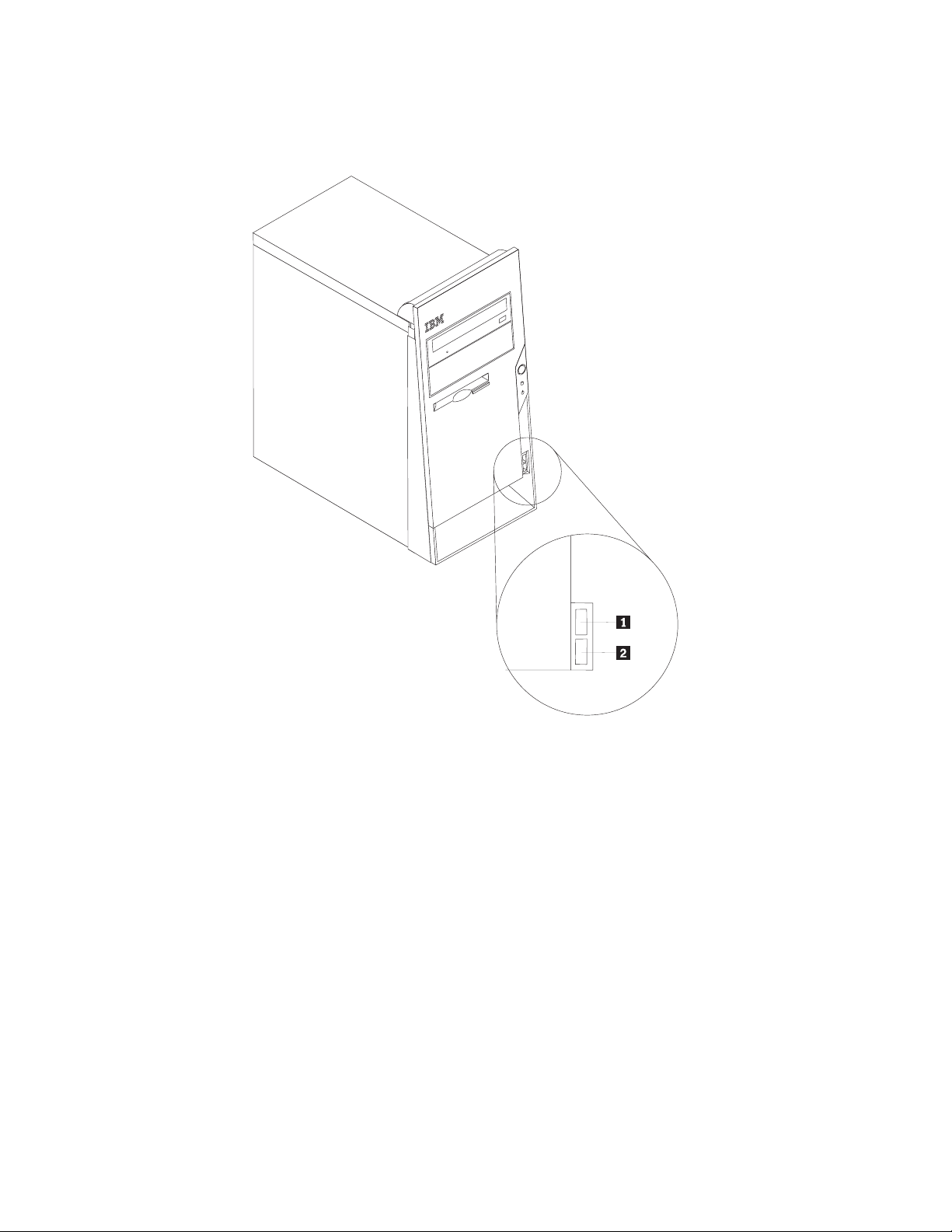
Locating connectors on the front of the computer
The following illustration shows the locations of the USB connectors on the front of
the computer.
1and 2USB connectors
20 Hardware Maintenance Manual
Page 27
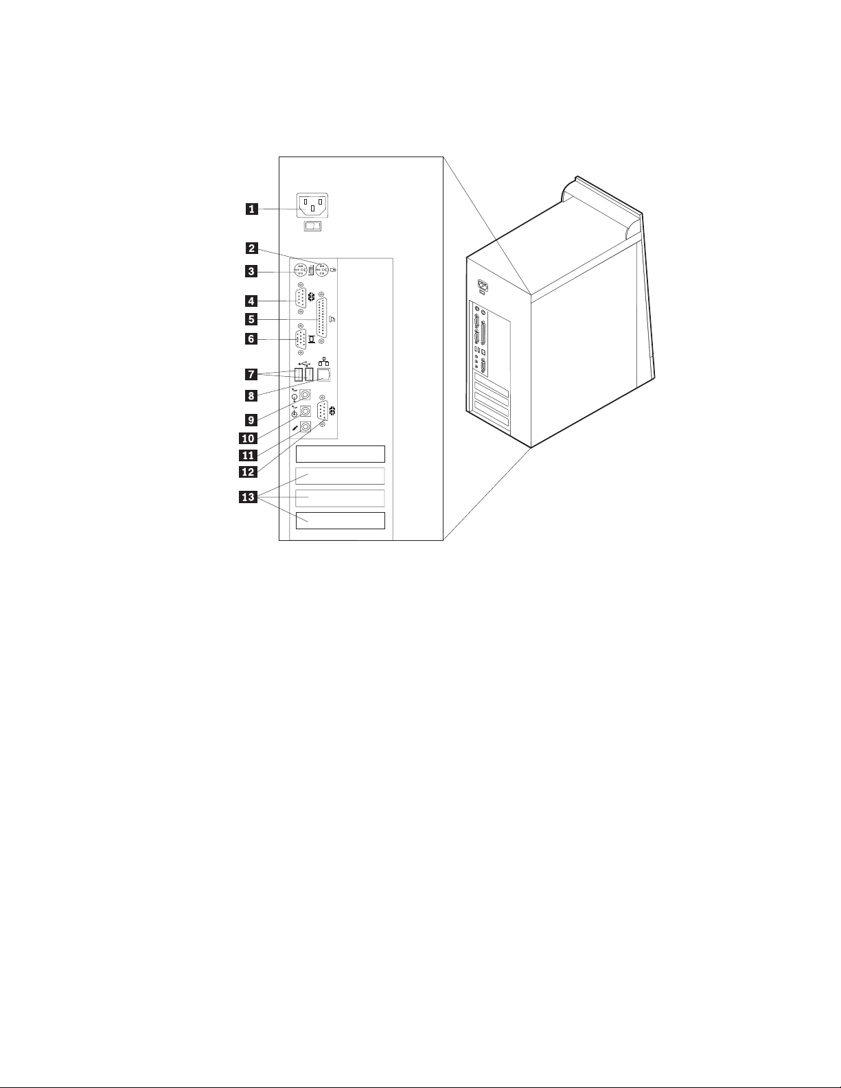
Locating connectors on the rear of the computer
The following illustration shows the locations of the connectors on the back of the
computer.
1 Power connector 8 Ethernet connector
2 Mouse connector 9 Audio line out connector
3 Keyboard connector 10 Audio line in connector
4 Serial connector 11 Microphone connector
5 Parallel connector 12 Serial connector
6 Monitor connector 13 PCI slots
7 USB connectors
Note: Some connectors on the rear of the computer are color-coded to help
determine where to connect the cables on the computer.
Chapter 5. Installing Options 21
Page 28

Connector Description
Mouse connector Used to attach a mouse, trackball, or other pointing device that
uses a standard mouse connector.
Keyboard connector Used to attach a keyboard that uses a standard keyboard
connector.
Serial connectors Used to attach an external modem, serial printer, or other
devices that use a 9-pin serial connector.
Parallel connector Used to attach a parallel printer, parallel scanner, or other
devices that use a 25-pin parallel connector.
USB connectors Used to attach a device that requires a Universal Serial Bus
(USB) connection, such as a USB scanner or USB printer. If
there are more than four USB devices, you can purchase a USB
hub, which can be used to connect additional USB devices.
Ethernet connector Used to attach an Ethernet cable for a local area network
(LAN).
Note: To operate the computer within FCC Class B limits, use
a Category 5 Ethernet cable.
Audio line out connector Used to send audio signals from the computer to external
Audio line in connector Used to receive audio signals from an external audio device,
Microphone connector Used to attach a microphone to the computer when recording
Obtaining device drivers
Device drivers can be obtained for operating systems that are not preinstalled at
http://www.ibm.com/pc/support/ on the World Wide Web. Installation
instructions are provided in README files with the device driver files.
Installing internal options
devices, such as powered stereo speakers (speakers with
built-in amplifiers), headphones, multimedia keyboards, or the
audio line in connector on a stereo system or other external
recording device.
such as a stereo system. When an external audio device is
attached, a cable is connected between the audio line out
connector of the device and the audio line in connector of the
computer.
voice or other sounds on the hard disk if speech-recognition
software is used.
The capabilities of the computer can be expanded by adding memory, drives, or
adapters. When installing an option, use these instructions along with the
instructions that come with the option.
22 Hardware Maintenance Manual
Page 29
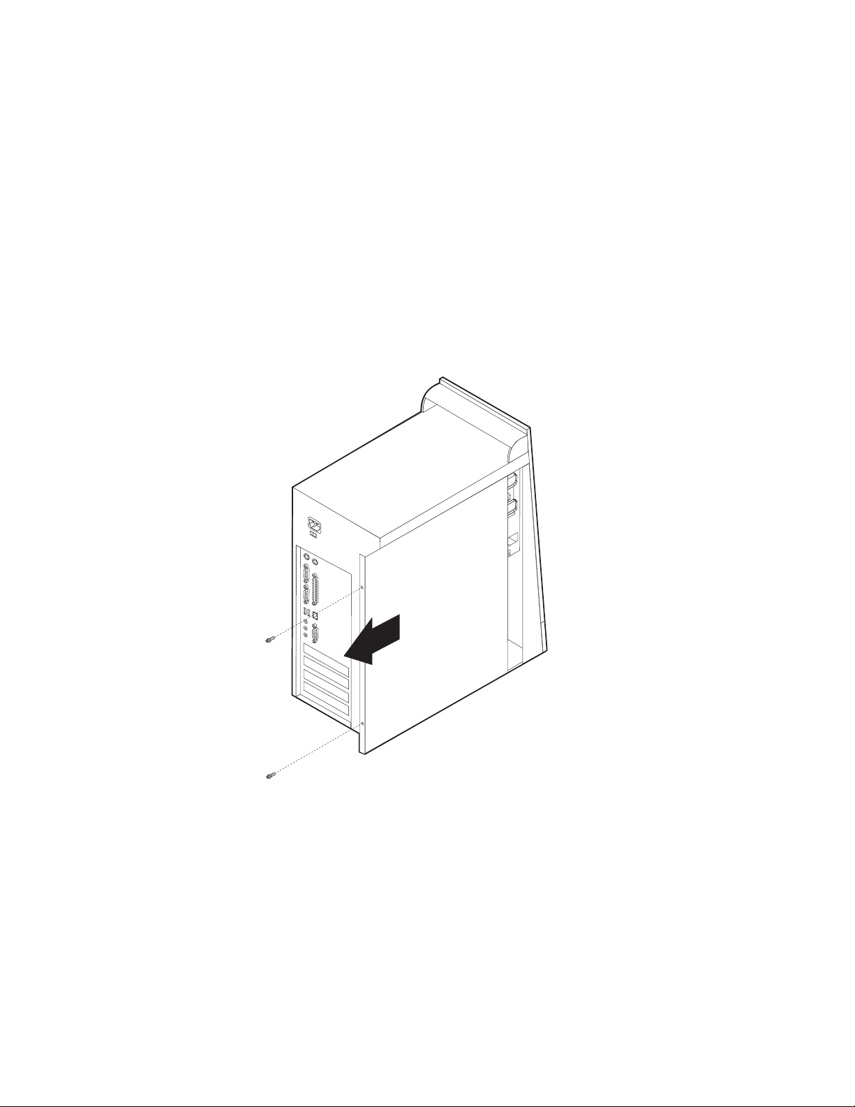
Removing the cover
Important:
See “Safety information” on page 93and “Handling electrostatic discharge-sensitive
devices” on page 96 before you begin.
To remove the cover:
1. Shut down the operating system, remove any media (diskettes, CDs, or tapes)
from the drives, and turn off all attached devices and the computer.
2. Unplug all power cords from electrical outlets.
3. Disconnect all cables attached to the computer. This includes power cords,
input/output (I/O) cables, and any other cables that are connected to the
computer.
4. Remove the two screws at the rear of the left side cover and slide the cover to
the rear to remove.
Chapter 5. Installing Options 23
Page 30
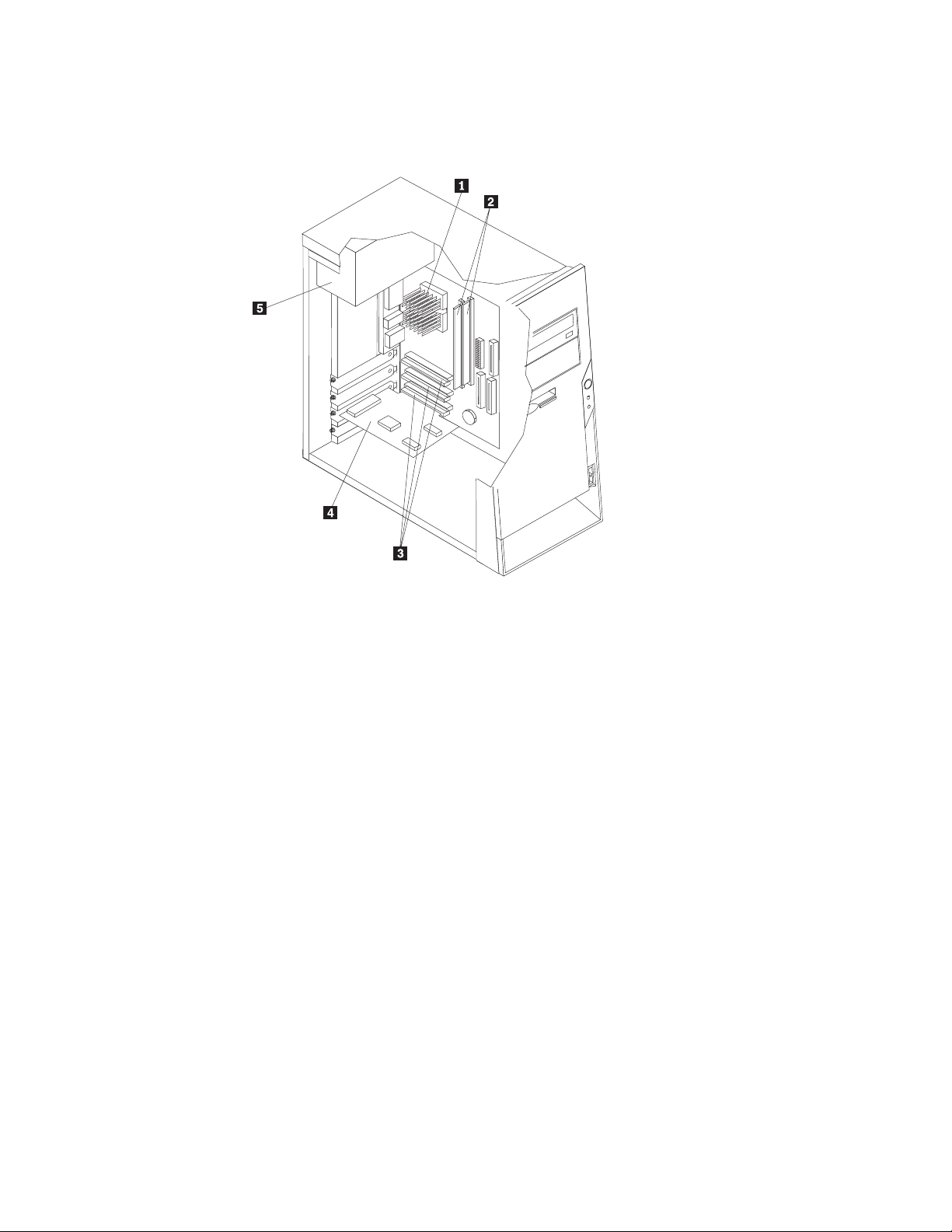
Locating components
The following illustration will help you locate the various components in the
computer.
1Microprocessor and heat sink 4PCI adapter
2DIMMs 5Power supply
3PCI slots
Identifying parts on the system board
The system board is the main circuit board in the computer. It provides basic
computer functions and supports a variety of devices that are IBM-installed or that
can be installed later.
24 Hardware Maintenance Manual
Page 31

The following illustration shows the locations of parts on the system board.
1 Fan connector 9 Secondary IDE connector
2 Microprocessor 10Primary IDE connector
3 DIMM connector 1 11Front USB connector
4 DIMM connector 2 12Battery
5 Power connector 13Virtual clear CMOS/BIOS recovery
6 Hard disk LED connector 14PCI slots
7 Power LED connector 15CD-ROM audio connector
8 Diskette drive connector 16Front panel connector
Installing memory
The computer has three connectors for installing dual in-line memory modules
(DIMMs) that provide up to a maximum of 512 MB of system memory.
Installing and removing DIMMs
When installing DIMMs, the following rules apply:
v Fill each system memory connector sequentially, starting at DIMM 1
v Use 3.3 V, synchronous, 168-pin, unbuffered, 133 MHz nonparity synchronous
dynamic random access memory (SDRAM)
v Use 64 MB, 128 MB, or 256 MB DIMMs in any combination
v DIMM heights of 38.1 mm (1.5 inches)
To install a DIMM:
1. Remove the cover. See “Removing the cover” on page 23.
2. You might have to remove an adapter to gain access to the DIMM slots. See
“Installing and removing adapters” on page 27.
jumper (JP14)
Chapter 5. Installing Options 25
Page 32

3. To locate the DIMM connectors. See “Identifying parts on the system board” on
page 24.
4. Open the retaining clips.
5. Make sure the notches in the DIMM align with the tabs on the connector. Push
or insert the DIMM straight down into the connector until the retaining clips
close.
Notches
To remove a DIMM:
1. Remove the cover. See “Removing the cover” on page 23.
2. You might have to remove an adapter to gain access to the DIMM slots. See
“Installing and removing adapters” on page 27.
3. To locate the DIMM connectors. See “Identifying parts on the system board” on
page 24.
4. Open the retaining clips.
5. Lift the DIMM out of the DIMM slot.
6. Close the retaining clips.
What to do next:
v Replace any adapters that were removed.
v Replace the power supply.
v To work with another option, go to the appropriate section.
v To complete the installation, go to “Replacing the cover and connecting the
cables” on page 33.
26 Hardware Maintenance Manual
Page 33

Installing and removing adapters
This section provides information and instructions for installing and removing
adapters. The computer has three expansion slots for PCI adapters. You can install
an adapter up to 228 mm (9 inches) long.
To install an adapter:
1. Remove the cover. See “Removing the cover” on page 23.
2. Remove the adapter slot cover for the appropriate expansion slot.
3. Remove the adapter from its static-protective package.
Chapter 5. Installing Options 27
Page 34

4. Install the adapter into the appropriate slot on the system board.
5. Secure the adapter with the screw as shown.
To remove an adapter:
1. Remove the cover. See “Removing the cover” on page 23.
28 Hardware Maintenance Manual
Page 35

2. Install the adapter into the appropriate slot on the system board.
3. Unscrew the adapter from the chassis.
4. Lift adapter out of PCI slot.
Installing and removing internal drives
This section provides information and instructions for installing and removing
internal drives.
Internal drives are devices that the computer uses to read and store data. You can
add drives to the computer to increase storage capacity and to enable the computer
to read other types of media. Some of the different drives that are available are:
v Hard disk drives
v CD drives or DVD drives
v Removable media drives
Internal drives are installed in bays. In this book, the bays are referred to as bay 1,
bay 2, and so on.
When installing an internal drive, it is important to note what type and size of
drive that can be installed in each bay. Also, it is important to correctly connect the
internal drive cables to the installed drive.
Drive specifications
Type 6029 computers come with the following IBM-installed drives:
v A CD-ROM, DVD-ROM, or CD-RW drive in bay 1 (some models)
v A 3.5-inch diskette disk drive in bay 3
v A 3.5-inch hard drive in bay 4
Any bay that does not have a drive installed has a static shield and bay panel
installed.
The following illustration shows the locations of the drive bays.
Chapter 5. Installing Options 29
Page 36

The following table describes some of the drives that can be installed in each bay
and their height requirements.
1Bay 1 - Maximum height: 43.0 mm (1.7 in.) CD-ROM drive (preinstalled in some
models)
5.25-inch hard disk drive
2Bay 2 - Maximum height: 43.0 mm (1.7 in.) 5.25-inch hard disk drive
3.5-inch hard disk drive (requires a
mounting bracket)
CD-ROM drive
DVD-ROM drive
CD-RW drive
3Bay 3 - Maximum height: 25.8 mm (1.0 in.) 3.5-inch diskette drive (preinstalled)
4Bay 4 - Maximum height: 25.8 mm (1.0 in.) 3.5-inch hard disk drive
Notes:
1. Drives that are greater than 43.0 mm (1.7 in.) high cannot be installed.
2. Install removable media (tape or CD) drives in the accessible bays (bay 1 or 2).
Installing a drive
To install an internal drive, follow these steps:
1. Remove the cover. See “Removing the cover” on page 23.
2. If the computer has a CD drive or DVD drive, you might need to remove the
signal and power cables from the drive.
3. Remove the bay panel from the drive bay by inserting a flat-blade screwdriver
at the end and gently prying it loose.
4. Remove the metal shield from the drive bay by inserting a flat-blade
screwdriver into one of the slots and gently prying it loose.
5. Make sure the drive that you are installing is set correctly as either a master or
a slave device.
v If it is the first CD drive or DVD drive, set it as a master device.
30 Hardware Maintenance Manual
Page 37

v If it is an additional CD drive or DVD drive, set it as a slave device.
v If it is a hard disk drive, set it as a slave device.
Refer to the documentation that comes with the drive for master/slave jumper
information.
6. Install the drive into the bay. Close and latch the drive securing lock to secure
the drive.
7. Each integrated drive electronics (IDE) drive requires two cables; a four-wire
power cable that connects to the power supply and a signal cable that connects
to the system board. For a CD-ROM drive, there might also be an audio cable.
The steps to connect an IDE drive are different depending on the type of drive
being connected. Use one of the following procedures for drive connection.
To connect the first IDE CD drive or DVD drive
1. Locate the three-connector signal cable that came with the computer or with the
new drive.
2. Locate the secondary IDE connector on the system board. See “Identifying parts
on the system board” on page 24.
3. Connect one end of the signal cable to the drive and the other to the secondary
IDE connector on the system board. To reduce electronic noise, use the
connectors at the end of the cable only.
4. Your computer has extra power connectors for additional drives. Connect a
power connector to the drive.
5. If there is a CD-ROM audio cable, connect it to the drive and to the system
board. See “Identifying parts on the system board” on page 24.
Chapter 5. Installing Options 31
Page 38

To connect an additional IDE CD drive or DVD drive
1. Locate the secondary IDE connector on the system board and the
three-connector signal cable. See “Identifying parts on the system board” on
page 24.
2. Connect the extra connector in the signal cable to the new CD drive or DVD
drive.
3. The computer has extra power connectors for additional drives. Connect a
power connector to the drive.
To connect an additional IDE hard disk drive
1. Locate the primary IDE connector on the system board. One end of the
three-connector cable connects to the hard disk drive and the other connects to
the system board. See “Identifying parts on the system board” on page 24.
2. Connect the extra connector in the signal cable to the new hard disk drive.
3. The computer has extra power connectors for additional drives. Connect a
power connector to the drive.
Changing the battery
The computer has a special type of memory that maintains the date, time, and
settings for built-in features, such as parallel-port assignments (configuration). A
battery keeps this information active when the computer is turned off.
The battery normally requires no charging or maintenance throughout its life;
however, no battery lasts forever. If the battery fails, the date, time, and
configuration information (including passwords) are lost. An error message is
displayed when the computer is turned on.
To change the battery:
1. Turn off the computer and all attached devices.
2. Unplug the power cord and remove the cover. See “Removing the cover” on
page 23.
3. Locate the battery. See “Identifying parts on the system board” on page 24.
4. If necessary, remove any adapters that impede access to the battery. See
“Installing and removing adapters” on page 27 for more information.
5. Remove the old battery.
6. Install the new battery.
32 Hardware Maintenance Manual
Page 39

7. Replace any adapters that were removed to gain access to the battery. See
“Installing and removing adapters” on page 27 for instructions for replacing
adapters.
8. Replace the cover, and plug in the power cord. See “Replacing the cover and
connecting the cables”.
Note: When the computer is turned on for the first time after battery
replacement, an error message might be displayed. This is normal after
replacing the battery.
9. Turn on the computer and all attached devices.
10. Use the Configuration/Setup Utility program to set the date and time and any
passwords.
Replacing the cover and connecting the cables
After working with options, reinstall any removed parts, replace the cover, and
reconnect any cables, including telephone lines and power cords. Also, depending
on the option that is installed, you might need to confirm the updated information
in the Configuration/Setup Utility program.
To replace the cover and connect cables to your computer:
1. Ensure that all components have been reassembled correctly and that no tools
or loose screws are left inside your computer.
2. Clear any cables that might impede the replacement of the cover.
Chapter 5. Installing Options 33
Page 40

3. Position the cover on the chassis so that the guides on the top and bottom of
the cover engage the chassis and push the cover to the closed position. Insert
the screws that secure the cover.
4. Reconnect the external cables and power cords to the computer. See “Installing
external options” on page 19.
5. To update the configuration, see “Setup Utility program” on page 12.
Important:
When the power cord is first plugged in, the computer might appear to turn
on for a few seconds and then turn off. This is a normal sequence to enable
the computer to initialize.
34 Hardware Maintenance Manual
Page 41

Chapter 6. FRU Removals
These removals are to be done by trained service technicians only.
Important: Before you install or remove any option, read “Safety information” on
page 93. These precautions and guidelines will help you work safely.
Replacing a microprocessor
To replace a microprocessor on any of the machine types, do the following:
1. Turn off the computer and peripheral devices and disconnect all external cables
and power cords; then, remove the cover. See “Removing the cover” on
page 23.
2. Press down and back on the silver tab holding the fansink in place to release it
and pivot the retaining bar off of the fansink notches.
3. To remove the fansink from the processor, twist the fansink to break the seal
formed by the thermal grease and remove.
Note: If the thermal grease seal cannot be broken, you may want to start up
the syststem to heat the processor and loosen the thermal grease.
4. Pull out and lift up the processor socket lever arm upward to its maximum
vertical position to release the processor.
5. Lift the processor out of the system board.
Note: When you install the new processor, make sure to reinstall the fansink to
insure proper cooling.
Removals
For removals, it may be easier to lay the system on it’s side.
Front bezel
To remove the front bezel, do the following:
1. Turn off the server and peripheral devices and disconnect all external cables
and power cords.
2. Remove the cover. See “Removing the cover” on page 23
© Copyright IBM Corp. 2001 35
Page 42

3. Push the bezel securing snaps out from inside the computer.
4. Pull the bezel off the computer.
Hard disk drive
To remove the hard disk drive, do the following:
1. Turn off the computer and peripheral devices and disconnect all external cables
and power cords; then, remove the cover. See “Removing the cover” on
page 23.
2. Remove the bezel. See “Front bezel” on page 35.
3. Disconnect all hard disk drive wires.
36 Hardware Maintenance Manual
Page 43

4. Remove the screws securing the hard disk drive.
5. Remove the disk drive.
Note: When replacing the hard disk drive, make sure you obtain the proper
Power supply
Recovery CD to install after you install the new hard drive.
To remove the power supply, do the following:
Chapter 6. FRU Removals 37
Page 44

1. Turn off the server and peripheral devices and disconnect all external cables
and power cords; then, remove the cover. See “Removing the cover” on
page 23.
2. Disconnect all power supply wires.
3. Remove the four screws holding the power supply to the back of the chassis.
4. Lift out the power supply.
System board
To remove the system board, do the following:
1. Turn off the server and peripheral devices and disconnect all external cables
and power cords; then, remove the cover. See “Removing the cover” on
page 23.
2. Disconnect all wires connected to the system board.
3. Remove the 5 screws that attach the system board to the chassis.
4. Lift out the system board.
38 Hardware Maintenance Manual
Page 45

Chapter 7. Symptom-to-FRU Index
The Symptom-to-FRU index lists error symptoms and possible causes. The most
likely cause is listed first. Always begin with ″General Checkout″ on page 3. This
index can also be used to help you decide which FRUs to have available when
servicing a computer. If you are unable to correct the problem using this index, go
to “Undetermined problems” on page 79.
Notes:
v If you have both an error message and an incorrect audio response, diagnose the error
message first.
v If you cannot run the diagnostic tests or you get a diagnostic error code when running a
test, but did receive a POST error message, diagnose the POST error message first.
v If you did not receive any error message, look for a description of your error symptoms
in the first part of this index.
v Check the hard disk drive jumper settings before you replace a hard disk drive.
Hard disk drive boot error
A hard disk drive boot error (error codes 1962 and I999030X) can have the
following causes.
Error FRU/Action
The start-up drive is not in the boot
sequence in configuration.
No operating system installed on the boot
drive.
The boot sector on the start-up drive is
corrupted.
The drive is defective. Replace the hard disk drive.
Check the configuration and ensure the
start-up drive is in the boot sequence.
Install an operating system on the boot
drive.
The drive must be formatted, do the
following:
1. Attempt to access and recover (back-up)
the failing hard disk drive.
2. Using the operating systems programs,
format the hard disk drive.
Power Supply Errors
If the power-on indicator is not on, the power supply fan is not running, or the
computer will not power-off, use the following procedures.
Check/Verify FRU/Action
Check the following for proper installation.
v Power Cord
v On/Off Switch connector
v On/Off Switch Power Supply connector
v System Board Power Supply connectors
v Microprocessor(s) connection
Check the power-on switch for continuity. Power Cord
© Copyright IBM Corp. 2001 39
Reseat
Page 46

Check/Verify FRU/Action
Check the power-on switch for continuity. Power-on Switch
40 Hardware Maintenance Manual
Page 47

Diagnostic error codes
Refer to the following diagnostic error codes when using the diagnostic tests. See
″Diagnostics″ on page 11 for the specific type for information about the Diagnostic
programs.
In the following index, X can represent any number.
Diagnostic Error Code FRU/Action
000-000-XXX
BIOS Test Passed
000-002-XXX
BIOS Timeout
000-024-XXX
BIOS Addressing test failure
000-025-XXX
BIOS Checksum Value error
000-026-XXX
FLASH data error
000-027-XXX
BIOS Configuration/Setup error
000-034-XXX
BIOS Buffer Allocation failure
000-035-XXX
BIOS Reset Condition detected
000-036-XXX
BIOS Register error
000-038-XXX
BIOS Extension failure
000-039-XXX
BIOS DMI data error
000-195-XXX
BIOS Test aborted by user
000-196-XXX
BIOS test halt, error threshold exceeded
1. No action
1. Flash the system
2. System board
1. Flash the system
2. System board
1. Flash the system
2. Boot block
3. System board
1. Flash the system
2. Boot block
3. System board
1. Run Setup
2. Flash the system
3. Boot block
4. System board
1. Reboot the system
2. Flash the system
3. Run memory test
4. System board
1. Flash the system
2. System board
1. Flash the system
2. Boot block
3. System board
1. Flash the system
2. Adapter card
3. System board
1. Flash the system
2. System board
1. Information
2. Re-start the test, if necessary
1. Press F3 to review the log file
2. Re-start the test to reset the log file
Chapter 7. Symptom-to-FRU Index 41
Page 48

Diagnostic Error Code FRU/Action
000-197-XXX
BIOS test warning
000-198-XXX
BIOS test aborted
000-199-XXX
BIOS test failed, cause unknown
000-250-XXX
BIOS APM failure
000-270-XXX
BIOS ACPI failure
001-000-XXX
System Test Passed
001-00X-XXX
System Error
001-01X-XXX
System Error
001-024-XXX
System Addressing test failure
001-025-XXX
System Checksum Value error
001-026-XXX
System FLASH data error
001-027-XXX
System Configuration/Setup error
001-032-XXX
System Device Controller failure
001-034-XXX
System Device Buffer Allocation failure
001-035-XXX
System Device Reset condition detected
001-036-XXX
System Register error
1. Make sure the component that is called
out is connected and/or enabled
2. Re-run test
3. Component that is called out in warning
statement
4. Component under test
1. If a component is called out, make sure
it is connected and/or enabled
2. Flash the system and re-test
3. Go to the ″Undetermined problems″
section
1. Go to the ″Undetermined problems″
section
2. Flash the system and re-test
3. Replace component under function test
1. Flash the system
2. System board
1. Flash the system
2. System board
1. No action
1. System board
1. System board
1. System board
1. Flash the system
2. System board
1. Flash the system
2. System board
1. Run Setup
2. Flash the system
3. System board
1. System board
1. Reboot the system
2. Flash the system
3. Run memory test
4. System board
1. System board
1. System board
42 Hardware Maintenance Manual
Page 49

Diagnostic Error Code FRU/Action
001-038-XXX
System Extension failure
001-039-XXX
System DMI data structure error
001-040-XXX
System IRQ failure
001-041-XXX
System DMA failure
001-195-XXX
System Test aborted by user
001-196-XXX
System test halt, error threshold exceeded
001-197-XXX
System test warning
1. Adapter card
2. System board
1. Flash the system
2. System board
1. Power-off/on system and re-test
2. System board
1. Power-off/on system and re-test
2. System board
1. Information
2. Re-start the test, if necessary
1. Press F3 to review the log file
2. Re-start the test to reset the log file
1. Make sure the component that is called
out is connected and/or enabled
2. Re-run test
3. Component that is called out in warning
statement
4. Component under test
001-198-XXX
System test aborted
1. If a component is called out, make sure
it is connected and/or enabled
2. Flash the system and re-test
3. Go to the ″Undetermined problems″
section
001-199-XXX
System test failed, cause unknown
1. Go to the ″Undetermined problems″
section
2. Flash the system and re-test
3. Replace component under function test
001-250-XXX
System ECC error
001-254-XXX
001-255-XXX
1. System board
1. System board
001-256-XXX
001-257-XXX
System DMA error
001-260-XXX
001-264-XXX
1. System board
System IRQ error
001-268-XXX
System IRQ1 failure
001-269-XXX
System IRQ2 failure
001-270-XXX
System IRQ3 failure
1. Device on IRQ1
2. System board
1. Device on IRQ2
2. System board
1. Device on IRQ3
2. System board
Chapter 7. Symptom-to-FRU Index 43
Page 50

Diagnostic Error Code FRU/Action
001-271-XXX
System IRQ4 failure
001-272-XXX
System IRQ5 failure
001-273-XXX
System IRQ6
(diskette drive) failure
001-274-XXX
System IRQ7 failure
001-275-XXX
System IRQ8 failure
001-276-XXX
System IRQ9 failure
001-277-XXX
System IRQ10 failure
001-278-XXX
System IRQ11 failure
001-279-XXX
System IRQ12 failure
001-280-XXX
System IRQ13 failure
001-281-XXX
System IRQ14
(hard disk drive) failure
001-282-XXX
System IRQ15 failure
001-286-XXX
001-287-XXX
001-288-XXX
System Timer failure
001-292-XXX
System CMOS
RAM error
001-293-XXX
System CMOS Battery
001-298-XXX
System RTC date/time update failure
001-299-XXX
System RTC periodic interrupt failure
001-300-XXX
System RTC Alarm failure
1. Device on IRQ4
2. System board
1. Device on IRQ5
2. System board
1. Diskette Cable
2. Diskette drive
3. System board
1. Device on IRQ7
2. System board
1. Device on IRQ8
2. System board
1. Device on IRQ9
2. System board
1. Device on IRQ10
2. System board
1. Device on IRQ11
2. System board
1. Device on IRQ12
2. System board
1. Device on IRQ13
2. System board
1. Hard disk drive cable
2. Hard disk drive
3. System board
1. Device on IRQ15
2. System board
1. System board
1. Run Setup and re-test
2. System board
1. Battery
2. System board
1. Flash the system
2. System board
1. System board
1. System board
44 Hardware Maintenance Manual
Page 51

Diagnostic Error Code FRU/Action
001-301-XXX
System RTC Century byte error
005-000-XXX
Video Test Passed
005-00X-XXX
Video error
005-010-XXX
005-011-XXX
005-012-XXX
1. Flash the system
2. System board
1. No action
1. Video card, if installed
2. System board
1. Video card, if installed
2. System board
005-013-XXX
Video Signal failure
005-016-XXX
Video Simple Pattern
test failure
1. Video Ram
2. Video card, if installed
3. System board
005-024-XXX
Video Addressing test failure
005-025-XXX
Video Checksum Value error
005-027-XXX
Video Configuration/Setup error
1. Video card, if installed
2. System board
1. Video card, if installed
2. System board
1. Run Setup
2. Video drivers update
3. Video card, if installed
4. System board
005-031-XXX
Video Device Cable failure
1. Video cable
2. Monitor
3. Video card, if installed
4. System board
005-032-XXX
Video Device Controller failure
005-036-XXX
Video Register error
005-038-XXX
System BIOS extension failure
005-040-XXX
Video IRQ failure
005-195-XXX
Video Test aborted by user
005-196-XXX
Video test halt, error threshold exceeded
1. Video card, if installed
2. System board
1. Video card, if installed
2. System board
1. Video card, if installed
2. System board
1. Video card, if installed
2. System board
1. Information
2. Re-start the test, if necessary
1. Press F3 to review the log file
2. Re-start the test to reset the log file
Chapter 7. Symptom-to-FRU Index 45
Page 52

Diagnostic Error Code FRU/Action
005-197-XXX
Video test warning
005-198-XXX
Video test aborted
005-199-XXX
Video test failed, cause unknown
005-2XX-XXX
005-3XX-XXX
Video subsystem error
006-000-XXX
Diskette interface Test Passed
006-0XX-XXX
Diskette interface error
006-195-XXX
Diskette interface Test aborted by user
006-196-XXX
Diskette interface test halt, error threshold
exceeded
006-197-XXX
Diskette interface test warning
006-198-XXX
Diskette interface test aborted
006-199-XXX
Diskette interface test failed, cause unknown
006-25X-XXX
Diskette interface Error
1. Make sure the component that is called
out is connected and/or enabled
2. Re-run test
3. Component that is called out in warning
statement
4. Component under test
1. If a component is called out, make sure
it is connected and/or enabled
2. Flash the system and re-test
3. Go to the ″Undetermined problems″
section
1. Go to the ″Undetermined problems″
section
2. Flash the system and re-test
3. Replace component under function test
1. Video card, if installed
2. System board
1. No action
1. Diskette drive Cable
2. Diskette drive
3. System board
1. Information
2. Re-start the test, if necessary
1. Press F3 to review the log file
2. Re-start the test to reset the log file
1. If a component is called out, make sure
it is connected and/or enabled
2. Re-run test
3. Component that is called out in warning
statement
4. Component under test
1. If a component is called out, make sure
it is connected and/or enabled
2. Flash the system and re-test
3. Go to the ″Undetermined problems″
section
1. Go to the ″Undetermined problems″
section
2. Flash the system and re-test
3. Replace component under function test
1. Diskette drive cable
2. Diskette drive
3. System board
46 Hardware Maintenance Manual
Page 53

Diagnostic Error Code FRU/Action
011-000-XXX
Serial port Interface Test Passed
011-001-XXX
Serial port Presence
1. No action
1. Remove external serial device, if
present
2. Run setup, enable port
3. System board
011-002-XXX
011-003-XXX
1. System board
Serial port Timeout/Parity error
011-013-XXX
011-014-XXX
1. System board
Serial port Control Signal/Loopback test
failure
011-015-XXX
Serial port External Loopback failure
011-027-XXX
Serial port Configuration/Setup error
1. Wrap plug
2. System board
1. Run Setup, enable port
2. Flash the system
3. System board
011-03X-XXX
011-04X-XXX
1. System board
Serial port failure
011-195-XXX
Serial port Test aborted by user
011-196-XXX
Serial port test halt, error threshold exceeded
011-197-XXX
Serial port test warning
1. Information
2. Re-start the test, if necessary
1. Press F3 to review the log file
2. Re-start the test to reset the log file
1. Make sure the component that is called
out is connected and/or enabled
2. Re-run test
3. Component that is called out in warning
statement
4. Component under test
011-198-XXX
Serial port test aborted
1. If a component is called out, make sure
it is connected and/or enabled
2. Flash the system and re-test
3. Go to the ″Undetermined problems″
section
011-199-XXX
Serial port test failed, cause unknown
1. Go to the ″Undetermined problems″
section
2. Flash the system and re-test
3. Replace component under function test
011-2XX-XXX
Serial port signal failure
014-000-XXX
Parallel port Interface Test Passed
1. External serial device
2. System board
1. No action
Chapter 7. Symptom-to-FRU Index 47
Page 54

Diagnostic Error Code FRU/Action
014-001-XXX
Parallel port Presence
014-002-XXX
014-003-XXX
Parallel port Timeout/Parity error
014-013-XXX
014-014-XXX
Parallel port Control Signal/Loopback test
failure
014-015-XXX
Parallel port External Loopback failure
014-027-XXX
Parallel port Configuration/Setup error
014-03X-XXX
014-04X-XXX
Parallel port failure
014-195-XXX
Parallel port Test aborted by user
014-196-XXX
Parallel port test halt, error threshold
exceeded
014-197-XXX
Parallel port test warning
014-198-XXX
Parallel port test aborted
014-199-XXX
Parallel port test failed, cause unknown
014-2XX-XXX
014-3XX-XXX
Parallel port failure
015-000-XXX
USB port Interface Test Passed
015-001-XXX
USB port Presence
1. Remove external parallel device, if
present
2. Run setup, enable port
3. System board
1. System board
1. System board
1. Wrap plug
2. System board
1. Run Setup, enable port
2. Flash the system
3. System board
1. System board
1. Information
2. Re-start the test, if necessary
1. Press F3 to review the log file
2. Re-start the test to reset the log file
1. Make sure the component that is called
out is connected and/or enabled
2. Re-run test
3. Component that is called out in warning
statement
4. Component under test
1. If a component is called out, make sure
it is connected and/or enabled
2. Flash the system and re-test
3. Go to the ″Undetermined problems″
section
1. Go to the ″Undetermined problems″
section
2. Flash the system and re-test
3. Replace component under function test
1. External parallel device
2. System board
1. No action
1. Remove USB device(s) and re-test
2. System board
48 Hardware Maintenance Manual
Page 55

Diagnostic Error Code FRU/Action
015-002-XXX
USB port Timeout
015-015-XXX
USB port External Loopback failure
015-027-XXX
USB port Configuration/Setup error
015-032-XXX
USB port Device Controller failure
015-034-XXX
USB port buffer
allocation failure
1. Remove USB device(s) and re-test
2. System board
1. Remove USB device(s) and re-test
2. System board
1. Flash the system
2. System board
1. System board
1. Reboot the system
2. Flash the system
3. Run memory test
4. System board
015-035-XXX
USB port Reset condition detected
015-036-XXX
USB port Register error
015-040-XXX
USB port IRQ failure
1. Remove USB device(s) and re-test
2. System board
1. System board
1. Run setup and check for conflicts
2. Flash the system
3. System board
015-195-XXX
USB port Test aborted by user
015-196-XXX
USB port test halt, error threshold exceeded
015-197-XXX
USB port test warning
1. Information
2. Re-start the test, if necessary
1. Press F3 to review the log file
2. Re-start the test to reset the log file
1. Make sure the component that is called
out is connected and/or enabled
2. Re-run test
3. Component that is called out in warning
statement
4. Component under test
015-198-XXX
USB port test aborted
1. If a component is called out, make sure
it is connected and/or enabled
2. Flash the system and re-test
3. Go to the ″Undetermined problems″
section
015-199-XXX
USB port test failed, cause unknown
1. Go to the ″Undetermined problems″
section
2. Flash the system and re-test
3. Replace component under function test
018-000-XXX
PCI Card Test Passed
018-0XX-XXX
PCI Card Failure
1. No action
1. Riser card, if installed
2. System board
Chapter 7. Symptom-to-FRU Index 49
Page 56

Diagnostic Error Code FRU/Action
018-195-XXX
PCI Card Test aborted by user
018-196-XXX
PCI Card test halt, error threshold exceeded
018-197-XXX
PCI Card test warning
018-198-XXX
PCI Card test aborted
018-199-XXX
PCI Card test failed, cause unknown
018-250-XXX
PCI Card Services error
020-000-XXX
PCI Interface Test Passed
020-0XX-XXX
PCI Interface error
020-195-XXX
PCI Test aborted by user
020-196-XXX
PCI test halt, error threshold exceeded
020-197-XXX
PCI test warning
020-198-XXX
PCI test aborted
1. PCI card
2. Information
3. Re-start the test, if necessary
1. Press F3 to review the log file
2. Re-start the test to reset the log file
1. Make sure the component that is called
out is connected and/or enabled
2. Re-run test
3. Component that is called out in warning
statement
4. Component under test
1. Make sure the component that is called
out is connected and/or enabled
2. Flash the system and re-test
3. Go to the ″Undetermined problems″
section
1. Go to the ″Undetermined problems″
section
2. Flash the system and re-test
3. Replace component under function test
1. PCI card
2. Riser card, if installed
3. System board
1. No action
1. PCI card
2. Riser card, if installed
3. System board
1. Information
2. Re-start the test, if necessary
1. Press F3 to review the log file
2. Re-start the test to reset the log file
1. Make sure the component that is called
out is connected and/or enabled
2. Re-run test
3. Component that is called out in warning
statement
4. Component under test
1. If a component is called out, make sure
it is connected and/or enabled
2. Flash the system and re-test
3. Go to the ″Undetermined problems″
section
50 Hardware Maintenance Manual
Page 57

Diagnostic Error Code FRU/Action
020-199-XXX
PCI test failed, cause unknown
1. Go to the ″Undetermined problems″
section
2. Flash the system and re-test
3. Replace component under function test
020-262-XXX
PCI system error
1. PCI card
2. Riser card, if installed
3. System board
025-000-XXX
IDE interface Test Passed
025-00X-XXX
025-01X-XXX
IDE interface failure
1. No action
1. IDE signal cable
2. Check power supply
3. IDE device
4. System board
025-027-XXX
IDE interface Configuration/Setup error
1. IDE signal cable
2. Flash the system
3. IDE device
4. System board
025-02X-XXX
025-03X-XXX
025-04X-XXX
IDE Interface failure
1. IDE signal cable
2. Check power supply
3. IDE device
4. System board
025-195-XXX
IDE interface Test aborted by user
025-196-XXX
IDE interface test halt, error threshold
exceeded
025-197-XXX
IDE interface test warning
1. Information
2. Re-start the test, if necessary
1. Press F3 to review the log file
2. Re-start the test to reset the log file
1. Make sure the component that is called
out is connected and/or enabled
2. Re-run test
3. Component that is called out in warning
statement
4. Component under test
025-198-XXX
IDE interface test aborted
1. If a component is called out, make sure
it is connected and/or enabled
2. Flash the system and re-test
3. Go to the ″Undetermined problems″
section
025-199-XXX
IDE interface test failed, cause unknown
1. Go to the ″Undetermined problems″
section
2. Flash the system and re-test
3. Replace component under function test
030-000-XXX
SCSI interface Test Passed
1. No action
Chapter 7. Symptom-to-FRU Index 51
Page 58

Diagnostic Error Code FRU/Action
030-00X-XXX
030-01X-XXX
SCSI interface failure
030-027-XXX
SCSI interface Configuration/Setup error
030-03X-XXX
030-04X-XXX
SCSI interface error
030-195-XXX
SCSI interface Test aborted by user
030-196-XXX
SCSI interface test halt, error threshold
exceeded
030-197-XXX
SCSI interface test warning
030-198-XXX
SCSI interface test aborted
030-199-XXX
SCSI interface test failed, cause unknown
035-000-XXX
RAID interface Test Passed
035-0XX-XXX
RAID interface Failure
035-195-XXX
RAID interface Test aborted by user
1. SCSI signal cable
2. Check power supply
3. SCSI device
4. SCSI adapter card, if installed
5. System board
1. SCSI signal cable
2. Flash the system
3. SCSI device
4. SCSI adapter card, if installed
5. System board
1. SCSI signal cable
2. Check power supply
3. SCSI device
4. SCSI adapter card, if installed
5. installed System board
1. Information
2. Re-start the test, if necessary
1. Press F3 to review the log file
2. Re-start the test to reset the log file
1. Make sure the component that is called
out is connected and/or enabled
2. Re-run test
3. Component that is called out in warning
statement
4. Component under test
1. If a component is called out, make sure
it is connected and/or enabled
2. Flash the system and re-test
3. Go to the ″Undetermined problems″
section
1. Go to the ″Undetermined problems″
section
2. Flash the system and re-test
3. Replace component under function test
1. No action
1. RAID signal cable
2. RAID device
3. RAID adapter card, if installed
4. System board
1. Information
2. Re-start the test, if necessary
52 Hardware Maintenance Manual
Page 59

Diagnostic Error Code FRU/Action
035-196-XXX
RAID interface test halt, error threshold
exceeded
035-197-XXX
RAID interface test warning
1. Press F3 to review the log file
2. Re-start the test to reset the log file
1. Make sure the component that is called
out is connected and/or enabled
2. Re-run test
3. Component that is called out in warning
statement
4. Component under test
035-198-XXX
RAID interface test aborted
1. If a component is called out, make sure
it is connected and/or enabled
2. Flash the system and re-test
3. Go to the ″Undetermined problems″
section
035-199-XXX
RAID interface test failed, cause unknown
1. Go to the ″Undetermined problems″
section
2. Flash the system and re-test
3. Replace component under function test
071-000-XXX
Audio port Interface Test Passed
071-00X-XXX
071-01X-XXX
071-02X-XXX
Audio port error
071-03X-XXX
Audio port failure
1. No action
1. Run Setup
2. Flash the system
3. System board
1. Speakers
2. Microphone
3. Audio card, if installed
4. System board
071-04X-XXX
Audio port failure
1. Run Setup
2. Audio card, if installed
3. System board
071-195-XXX
Audio port Test aborted by user
071-196-XXX
Audio port test halt, error threshold
exceeded
071-197-XXX
Audio port test warning
1. Information
2. Re-start the test, if necessary
1. Press F3 to review the log file
2. Re-start the test to reset the log file
1. Make sure the component that is called
out is connected and/or enabled
2. Re-run test
3. Component that is called out in warning
statement
4. Component under test
071-198-XXX
Audio port test aborted
1. If a component is called out, make sure
it is connected and/or enabled
2. Flash the system and re-test
3. Go to the ″Undetermined problems″
section
Chapter 7. Symptom-to-FRU Index 53
Page 60

Diagnostic Error Code FRU/Action
071-199-XXX
Audio port test failed, cause unknown
071-25X-XXX
Audio port failure
080-000-XXX
Game Port interface Test Passed
080-XXX-XXX
Game Port interface Error
080-195-XXX
Game Port interface Test aborted by user
080-196-XXX
Game Port interface test halt, error threshold
exceeded
080-197-XXX
Game Port interface test warning
080-198-XXX
Game Port interface test aborted
080-199-XXX
Game Port interface test failed, cause
unknown
086-000-XXX
Mouse Port interface Test Passed
086-001-XXX
Mouse Port interface Presence
086-032-XXX
Mouse Port interface Device controller
failure
086-035-XXX
Mouse Port interface Reset
086-040-XXX
Mouse Port interface IRQ failure
086-195-XXX
Mouse Port interface Test aborted by user
1. Go to the ″Undetermined problems″
section
2. Flash the system and re-test
3. Replace component under function test
1. Speakers
2. Audio card, if installed
3. System board
1. No action
1. Remove the game port device and
re-test the system
1. Information
2. Re-start the test, if necessary
1. Press F3 to review the log file
2. Re-start the test to reset the log file
1. Make sure the component that is called
out is connected and/or enabled
2. Re-run test
3. Component that is called out in warning
statement
4. Component under test
1. If a component is called out, make sure
it is connected and/or enabled
2. Flash the system and re-test
3. Go to the ″Undetermined problems″
section
1. Go to the ″Undetermined problems″
section
2. Flash the system and re-test
3. Replace component under function test
1. No action
1. Mouse
2. System board
1. Mouse
2. System board
1. Mouse
2. System board
1. Run Setup
2. Mouse
3. System board
1. Information
2. Re-start the test, if necessary
54 Hardware Maintenance Manual
Page 61

Diagnostic Error Code FRU/Action
086-196-XXX
Mouse Port interface test halt, error
threshold exceeded
086-197-XXX
Mouse Port interface test warning
1. Press F3 to review the log file
2. Re-start the test to reset the log file
1. Make sure the component that is called
out is connected and/or enabled
2. Re-run test
3. Component that is called out in warning
statement
4. Component under test
086-198-XXX
Mouse Port interface test aborted
1. If a component is called out, make sure it
is connected and/or enabled
2. Flash the system and re-test
3. Go to the ″Undetermined problems″
section
086-199-XXX
Mouse Port interface test failed, cause
unknown
1. Go to the ″Undetermined problems″
section
2. Flash the system and re-test
3. Replace component under function test
089-000-XXX
Microprocessor Test Passed
089-XXX-XXX
Microprocessor failure
089-195-XXX
Microprocessor Test aborted by user
089-196-XXX
Microprocessor test halt, error threshold
exceeded
089-197-XXX
Microprocessor test warning
1. No action
1. Microprocessor(s)
2. System board
1. Information
2. Re-start the test, if necessary
1. Press F3 to review the log file
2. Re-start the test to reset the log file
1. Make sure the component that is called
out is connected and/or enabled
2. Re-run test
3. Component that is called out in warning
statement
4. Component under test
089-198-XXX
Microprocessor test aborted
1. Flash the system and re-test
2. Go to the ″Undetermined problems″
section
089-199-XXX
Microprocessor test failed, cause unknown
1. If a component is called out, make sure
it is connected and/or enabled
2. Go to the ″Undetermined problems″
section
3. Flash the system and re-test
4. Replace component under function test
170-000-XXX
Voltage Sensor(s) Test Passed
170-0XX-XXX
Voltage Sensor(s) failure
1. No action
1. Flash system
2. System board
Chapter 7. Symptom-to-FRU Index 55
Page 62

Diagnostic Error Code FRU/Action
170-195-XXX
Voltage Sensor(s) Test aborted by user
170-196-XXX
Voltage Sensor(s) test halt, error threshold
exceeded
170-197-XXX
Voltage Sensor(s) test warning
170-198-XXX
Voltage Sensor(s) test aborted
170-199-XXX
Voltage Sensor(s) test failed, cause unknown
170-250-XXX
170-251-XXX
Voltage Sensor(s) Voltage limit error
170-254-XXX
Voltage Sensor(s) Voltage Regulator Module
error
175-000-XXX
Thermal Sensor(s) Test Passed
175-0XX-XXX
Thermal Sensor(s) failure
175-195-XXX
Thermal Sensor(s) Test aborted by user
175-196-XXX
Thermal Sensor(s) test halt, error threshold
exceeded
175-197-XXX
Thermal Sensor(s) test warning
175-198-XXX
Thermal Sensor(s) test aborted
1. Information
2. Re-start the test, if necessary
1. Press F3 to review the log file
2. Re-start the test to reset the log file
1. Make sure the component that is called
out is connected and/or enabled
2. Re-run test
3. Component that is called out in warning
statement
4. Component under test
1. If a component is called out, make sure
it is connected and/or enabled
2. Flash the system and re-test
3. Go to the ″Undetermined problems″
section
1. Go to the ″Undetermined problems″
section
2. Flash the system and re-test
3. Replace component under function test
1. Power supply
2. System board
1. Voltage Regulator Module (VRM)
2. Microprocessor
3. System board
1. No action
1. Flash system
2. System board
1. Information
2. Re-start the test, if necessary
1. Press F3 to review the log file
2. Re-start the test to reset the log file
1. Make sure the component that is called
out is connected and/or enabled
2. Re-run test
3. Component that is called out in warning
statement
4. Component under test
1. If a component is called out, make sure
it is connected and/or enabled
2. Flash the system and re-test
3. Go to ″Undetermined problems″ section
56 Hardware Maintenance Manual
Page 63

Diagnostic Error Code FRU/Action
175-199-XXX
Thermal Sensor(s) test failed, cause
unknown
1. Go to the ″Undetermined problems″
section
2. Flash the system and re-test
3. Replace component under function test
175-250-XXX
175-251-XXX
Thermal Sensor(s) limit error
1. Check fans
2. Check Power supply
3. Microprocessor
4. System board
185-000-XXX
Asset Security Test Passed
185-XXX-XXX
Asset Security failure
185-278-XXX
Asset Security Chassis Intrusion
1. No action
1. Flash system
2. System board
1. Assure Asset Security Enabled
2. C2 Cover Switch
3. System board
201-000-XXX
System Memory Test Passed
201-XXX-XXX
System Memory error
1. No action
1. Replace the memory module called out
by the test
2. System board
202-000-XXX
System Cache Test Passed
202-XXX-XXX
System Cache error
1. No action
1. Cache, if removable
2. System board
3. Microprocessor
206-000-XXX
Diskette Drive Test Passed
206-XXX-XXX
Diskette Drive error
1. No action
1. Diskette Drive Cable
2. Check power supply voltages
3. Diskette drive
4. System board
215-000-XXX
CD-ROM Drive Test Passed
215-XXX-XXX
CD-ROM Drive error
1. No action
1. CD-ROM Drive Cable
2. Check power supply voltages
3. CD-ROM drive
4. System board
217-000-XXX
Hard Disk Drive Test Passed
217-25X-XXX
217-26X-XXX
Hard Disk Drive (IDE) error
1. No action
1. Hard Disk Drive Cable
2. Check power supply voltages
3. Hard Disk drive (IDE)
4. System board
Chapter 7. Symptom-to-FRU Index 57
Page 64

Diagnostic Error Code FRU/Action
217-28X-XXX
217-29X-XXX
Hard Disk Drive (SCSI) error
220-000-XXX
Hi-Capacity Cartridge Drive Test Passed
220-XXX-XXX
Hi-Capacity Cartridge Drive error
301-XXX-XXX
Keyboard error
301-000-XXX
Keyboard Test Passed
302-000-XXX
Mouse Test Passed
302-XXX-XXX
Mouse error
303-000-XXX
Joystick Test Passed
303-XXX-XXX
Joystick error
305-000-XXX
Monitor DDC Test Passed
305-250-XXX
Monitor DDC self test failure
415-000-XXX
Modem Test Passed
415-XXX-XXX
Modem error
1. Hard Disk Drive Cable
2. Check power supply voltages
3. Hard Disk drive (SCSI)
4. SCSI adapter card
5. System board
1. No action
1. Remove the Hi-Capacity Cartridge
Drive and re-test the system
1. Keyboard
2. Check and test mouse
3. System board
1. No action
1. No action
1. Mouse
2. Check and test Keyboard
3. System board
1. No action
1. Remove the Joystick and re-test the
system
1. No action
1. Run Setup to enable DDC
2. Cable
3. Monitor
4. Video card
5. System board
1. No action
1. Remove the Modem and re-test the
system
58 Hardware Maintenance Manual
Page 65

Beep symptoms
Beep symptoms are short tones or a series of short tones separated by pauses
(intervals without sound). See the following examples.
Beeps Description
1-2-X
4 Four continuous beeps
v One beep
v A pause (or break)
v Two beeps
v A pause (or break)
v Any number of breaks
Use the following table to diagnose beep symptoms.
Beep Symptom FRU/Action
1-1-3
CMOS read-write error
1-2-2-3
ROM BIOS check error
1-2-1
Programmable Interval Timer failed
1-2-2 DMA Initialization failed
1-2-3 DMA page register write/read failed
1-2-4 RAM refresh verification failed
1-3-3-1 1st 64K RAM test failed
1-3-2 1st 64K RAM parity test failed
2-2-3-1
Interrupt vector loading test failed
2-1-1 Secondary DMA register failed
2-1-2
Primary DMA register failed
2-1-3 Primary interrupt mask register failed
2-1-4 Secondary interrupt mask register
failed
2-2-1 Interrupt vector loading failed
1-3-1-3 Keyboard controller failed
2-2-3
CMOS power failure and checksum checks
failed
1. Run Setup
2. System Board
1. System Board
1. System Board
1. System Board
1. System Board
1. DIMM
2. System Board
1. DIMM
2. System Board
1. DIMM
2. Processor
3. System Board
1. System Board
1. System Board
1. System Board
1. System Board
1. System Board
1. System Board
1. System Board
2. Keyboard
1. Battery
2. System Board
Chapter 7. Symptom-to-FRU Index 59
Page 66

Beep Symptom FRU/Action
2-2-4 CMOS configuration info validation
failed
2-3-1 Screen initialization failed
2-3-2 Screen memory failed
2-3-3 Screen retrace failed
1-2 Search for video ROM failed
All other beep code sequences
Continuous beep
Repeating short beeps
1. Battery
2. System Board
1. Jumper on J28
2. System Board
1. System Board
1. System Board
1. System Board
1. System Board
1. System Board
1. Keyboard stuck key
2. Keyboard Cable
3. System Board
60 Hardware Maintenance Manual
Page 67

No-beep symptoms
Symptom/Error FRU/Action
No beep during POST but computer works
correctly.
No beep during POST.
1. System Board
1. See “Undetermined problems” on page
79.
2. System Board
3. Memory Module
4. Any Adapter or Device
5. Riser Card
6. Power Cord
7. Power Supply
Chapter 7. Symptom-to-FRU Index 61
Page 68

POST error codes
Each time you power-on the system, it performs a series of tests that check the
operation of the system and some options. This series of tests is called the
Power-On Self-Test,orPOST. POST does the following operations.
v Checks some basic system-board operations
v Checks the memory operation
v Starts the video operation
v Verifies that the diskette drive is working
v Verifies that the hard disk drive is working
If the POST finishes without detecting any problems, a single beep sounds and the
first screen of the operating system or application program appears.
Note:
Type 6029 computers default to come up quiet (no beep and no memory count and
checkpoint code display) when no errors are detected by POST.
To enable beep and memory count and checkpoint code display when a successful POST
occurs, do the following:
1. Select Start Options in the Configuration/Setup Utility program (see “Setup Utility
2. Set Power-On Self-Test to Enhanced.
program” on page 12).
If the POST detects a problem, an error message appears on the screen. A single
problem can cause several error messages to appear. When you correct the cause of
the first error message, the other error messages probably will not appear on the
screen the next time you turn on the system.
In the following index, X can represent any number.
POST Error Code FRU/Action
000
SCSI Adapter not enabled
02X
08X
Check SCSI terminator installation.
101
System board interrupt failure
102
System board timer error
106
110
System board memory parity error
1. Verify adapter device and Bus Master
fields are enabled in PCI configuration
program. See documentation shipped
with computer.
1. SCSI Adapter
1. SCSI Cable
2. SCSI Terminator
3. SCSI Device
4. SCSI Adapter
1. System Board
1. System Board
1. System Board
1. Memory Module
2. System Board
62 Hardware Maintenance Manual
Page 69

POST Error Code FRU/Action
111
I/O channel parity error
1. Reseat adapters
2. Any adapter
3. Riser card
4. System Board
114
Adapter ROM error
1. Adapter Memory
2. System Board
3. Riser card
129
Internal cache test error
1. Processor
2. L2 Cache Memory
3. System Board
135 Fan failure
1. Fan
2. System board
151
System board failure
161
Bad CMOS battery
1. System Board
1. Run Setup
2. CMOS Backup Battery (see “Safety
information” on page 93)
3. System Board
162
Configuration mismatch
1. Run Setup and verify Configuration
2. Had a device been added, removed,
changed location? If not, suspect that
device.
3. Power-on external devices first, then
power-on computer
4. CMOS Backup Battery (see “Safety
information” on page 93)
System Board
5. System Board
163
Date and Time Incorrect
1. Time and Date Set
2. CMOS Backup Battery (see “Safety
information” on page 93)
3. System Board
164
Memory Size Error
1. Run Setup. Check System Summary
menu for memory size change. (See
“Setup Utility program” on page 12.)
2. Run the Extended Memory Diagnostic
tests
166
Boot Block Check Sum Error
1. Run Flash Recovery using Boot Block.
See “Flash recovery boot block jumper”
on page 90.
2. System Board
167
No Processor BIOS Update Found
1. Run Setup. Check Stepping level for
the BIOS level needed, then perform
the flash update.
2. Processor
Chapter 7. Symptom-to-FRU Index 63
Page 70

POST Error Code FRU/Action
168
Alert on LAN error
17X, 18X
175 Primary Copy of Secure Data is
damaged
176 The System has been tampered with
177
Corrupted Administrator Password
178
179 Boot Integrity Services Segment Error
183
184
Asset Control Antenna not detected
185
Corrupted boot sequence
186 Security Hardware Control Logic Error
187
189
190
System Security: Invalid Remote Change
Requested
191 System Security: IBM Embedded
Security Hardware Reset
193 System Security: IBM Embedded
Security Hardware Removed
194 System Security: Asset ID Antenna has
been Removed
195 System Security: Asset ID Antenna has
been Installed
196 System Tampered Cleared
1XX
Not listed above
201, 20X
Memory data error
1. Run Setup. Check to see that Ethernet
and Alert on LAN are enabled.
2. System Board
1. C2 Security
1. Run Configuration. See “Setup Utility
program” on page 12.
2. System Board
1. Covers were removed from the
computer
1. System Board
1. System Board
1. System Board
1. Enter the administrator password
1. Make sure Asset Care and Asset ID are
enabled in Configuration/Setup
2. RFID Antenna
3. System Board
1. Set configuration and reinstall the boot
sequence
1. System Board
1. Clear Administration password
2. System Board
1. More than three password attempts
were made to access the computer
1. System Board
1. System Board
1. System Board
1. System Board
1. System Board
1. System Board
1. System Board
1. Run Enhanced Diagnostics Memory
Te s t
2. Memory Module
3. System Board
64 Hardware Maintenance Manual
Page 71

POST Error Code FRU/Action
225
229
External cache test error
262
POST detected a base memory or extended
memory type error
1. Unsupported Memory
1. L2 Cache Memory
2. System Board
1. Run Setup. Check System Summary
menu for memory. (See “Setup Utility
program” on page 12.)
2. Run the Extended Memory Diagnostic
tests.
301 Keyboard Error
1. Keyboard
2. Keyboard Cable
3. System Board
303
With an 8603 error
1. Mouse
2. Keyboard
3. Keyboard Cable
4. System Board
303
With no 8603 error
1. Keyboard
2. Keyboard Cable
3. System Board
3XX
Not listed above
1. Keyboard
2. Keyboard Cable
3. System Board
5XX
1. Video Adapter (if installed)
2. System Board
601
1. Diskette Drive A
2. Diskette Drive Cable
3. System Board
4. Riser card
602
1. Bad Diskette?
2. Verify Diskette and retry
604
And able to run diagnostics
1. Run Setup and verify diskette
configuration settings
2. Diskette Drive A/B
3. Diskette Drive Cable
4. System Board
5. Riser card
605
POST cannot unlock the diskette drive
1. Diskette Drive
2. Diskette Drive Cable
3. System Board
4. Riser card
662 Configuration Change has occured
1. Diskette drive configuration error or
wrong diskette drive type; run Setup
Configuration
Chapter 7. Symptom-to-FRU Index 65
Page 72

POST Error Code FRU/Action
6XX
Not listed above
1. Diskette Drive
2. System Board
3. Riser card
4. External Drive Adapter
5. Diskette Drive Cable
6. Power Supply
762
Math coprocessor configuration error
1. Run Setup
2. Processor
3. System Board
7XX
Not listed above
962
Parallel port configuration error
1. Processor
2. System Board
1. Run Configuration
2. Parallel Adapter (if installed)
3. System Board
9XX
1. Printer
2. System Board
1047
107X
Check SCSI terminator installation
1. 16-Bit AT
1. Check SCSI terminator installation
2. SCSI Cable
3. SCSI Terminator
4. SCSI Device
5. SCSI Adapter
1101
Serial connector error, possible system board
1. Run Enhanced Diagnostics
failure
1101, 1102, 1106, 1108, 1109
1. System Board
2. Any Serial Device
1107
1. Communications Cable
2. System Board
1102
Card selected feedback error
1103
Port fails register check
1106
Serial option cannot be turned off
1107
1. Run Enhanced Diagnostics
1. Run Enhanced Diagnostics
2. System Board
1. Run Enhanced Diagnostics
2. System Board
1. Serial Device Cable
2. System Board
1110
Register test failed
1116
Interrupt error
1. Run Enhanced Diagnostics
2. System Board
1. Run Enhanced Diagnostics
™
Fast SCSI Adapter
66 Hardware Maintenance Manual
Page 73

POST Error Code FRU/Action
1117
Failed baud rate test
1162
Serial port configuration error
1. Run Enhanced Diagnostics
1. Run Configuration
2. Serial Adapter
(if installed)
3. System Board
11XX
Not listed above
1201
1. System Board
1. System Board
2. Any Serial Device
1202, 1206, 1208, 1209, 12XX
1. Dual Async Adapter/A
2. System Board
3. Any Serial Device
1207
1. Communications Cable
2. Dual Async Adapter/A
13XX
1402
1. Game Adapter
Information only
Printer not ready
1403
Information only
No paper error, or interrupt failure
1404
System board timeout failure
1405
Parallel adapter error
1406
Presence test error
14XX
Not listed above. Check printer before
replacing system board
15XX
1692
Boot sequence error
16XX
1762
Hard disk drive configuration error
1780 (Disk Drive 0)
1781 (Disk Drive 1)
1782 (Disk Drive 2)
1783 (Disk Drive 3)
1. Run Enhanced Diagnostics
1. Run Enhanced Diagnostics
1. Run Enhanced Diagnostics
1. Printer
2. System Board
1. SDLC Adapter
1. Run FDISK to ensure at least one active
partition is set active
1. 36/38 Workstation Adapter
1. Run Configuration. (See “Setup Utility
program” on page 12.)
1. Hard Disk Drive
2. System Board
3. Riser card
4. Hard Disk Cable
5. Power Supply
Chapter 7. Symptom-to-FRU Index 67
Page 74

POST Error Code FRU/Action
1800 PCI/PnP Error! No Hardware Interrupt
Available
1801 PCI/PnP Error! No Space Available to
Shadow ROM
1802 PCI/PnP Error! Not Enough I/O Space
Available
1803 PCI/PnP Error! Not Enough Memory
Space Available
1804 PCI/PnP Error! Not Enough Real
Memory Space Available
1805 PCI/PnP Error! Adapter ROM
Checksum Error
1. Run Setup and verify PCI/ISA
configuration settings.
2. If necessary, set ISA adapters to Not
available to allow PCI adapters to
properly configure.
3. Remove any suspect ISA adapters.
4. Rerun diagnostics.
5. PCI Adapter
1. Run Setup and verify PCI/ISA
configuration settings.
2. If necessary, set ISA adapters to Not
available to allow PCI adapters to
properly configure.
3. Remove any suspect ISA adapters.
4. Rerun diagnostics.
5. PCI Adapter
1. Run Setup and verify PCI/ISA
configuration settings.
2. If necessary, set ISA adapters to Not
available to allow PCI adapters to
properly configure.
3. Remove any suspect ISA adapters.
4. Rerun diagnostics.
5. PCI Adapter
1. Run Setup and verify PCI/ISA
configuration settings.
2. If necessary, set ISA adapters to Not
available to allow PCI adapters to
properly configure.
3. Remove any suspect ISA adapters.
4. Rerun diagnostics.
5. PCI Adapter
1. Run Setup and verify PCI/ISA
configuration settings.
2. If necessary, set ISA adapters to Not
available to allow PCI adapters to
properly configure.
3. Remove any suspect ISA adapters.
4. Rerun diagnostics.
5. PCI Adapter
1. Run Setup and verify PCI/ISA
configuration settings.
2. If necessary, set ISA adapters to Not
available to allow PCI adapters to
properly configure.
3. Remove any suspect ISA adapters.
4. Rerun diagnostics.
5. PCI Adapter
68 Hardware Maintenance Manual
Page 75

POST Error Code FRU/Action
180X, 188X
PCI configuration or resource error
1. Run Setup and verify PCI/ISA
configuration settings.
2. If necessary, set ISA adapters to Not
available to allow PCI adapters to
properly configure.
3. Remove any suspect ISA adapters.
4. Rerun diagnostics.
5. PCI Adapter
1962
No operating system found
209X
1. Press F1 to repeat boot sequence.
1. Diskette Drive
2. Diskette Cable
20XX
Not listed above
21XX
1. BSC Adapter
1. SCSI Device
2. 16-bit AT Fast SCSU adapter
3. Alternate BSC adapter
2401, 2402
If screen colors change
2401, 2402
If screen colors are OK
2409
2410
1. Display
1. System Board
2. Display
1. Display
1. System Board
2. Display
2462
Video memory configuration error
1. Check cable connections
2. Run Setup and verify video
configuration settings
3. Video Memory Modules
4. Video Adapter (if installed)
5. System Board
4611, 4630
1. Multiport/2 Interface Board
2. Multiport/2 Adapter
4612, 4613, 4640, 4641
1. Memory Module Package
2. Multiport/2 Adapter
4650
46XX
Not listed above
1. Multiport/2 Interface Cable
1. Multiport/2 Adapter
2. Multiport/2 Interface
Board
3. Memory Module
5600
1. Financial System Controller Adapter
Chapter 7. Symptom-to-FRU Index 69
Page 76

POST Error Code FRU/Action
5962
An IDE device (other than hard drive)
configuration error
62XX
63XX
64XX
71XX
74XX
76XX
78XX
79XX
80XX
84XX
8601, 8602
8603, 8604 Pointing Device Error
86XX
Not listed above
89XX
91XX
96XX
10101, 10102, 10104, 10105, 10106, 10107,
10108, 10109, 10111,
10112, 10113, 10114,
10115, 10116
1. Run Configuration
2. CD-ROM Drive
3. CD-ROM Adapter
4. Zip or other ATAPI device
5. System Board
6. Riser card
1. 1st Store Loop Adapter
2. Adapter Cable
1. 2nd Store Loop Adapter
2. Adapter Cable
1. Network Adapter
1. Voice Adapter
1. Video Adapter
(if installed)
1. Page Printer Adapter
1. High Speed Adapter
1. 3117 Adapter
1. PCMCIA Adapter
1. Speech Adapter
2. Speech Control Assembly.
1. Pointing Device (Mouse)
2. System Board
1. System Board
2. Pointing Device
(Mouse)
1. Mouse
2. System Board
1. PC Music Adapter
2. MIDI Adapter Unit
1. Optical Drive
2. Adapter
1. SCSI Adapter
2. Any SCSI Device
3. System Board
4. Riser card
1. Have customer verify correct operating
system device drivers are installed and
operational.
2. Modem
70 Hardware Maintenance Manual
Page 77

POST Error Code FRU/Action
10103, 10110, 101171
1. System Board
2. Data/Fax Modem
3. Riser card
10117
Not listed above
1. Check system speaker
2. Check PSTN cable
3. External DAA
(if installed)
4. Modem
10118
1. Run Diagnostics and verify the correct
operation of the modem slot
2. Modem
10119
1. Diagnostics detected a non-IBM modem
2. Modem
10120
1. Check PSTN Cable
2. External DAA
(if installed)
3. Modem
10132, 10133, 10134,
10135, 10136, 10137,
1. Modem
10138, 10139, 10140,
10141, 10142, 10143,
10144, 10145, 10146,
10147, 10148, 10149,
10150, 10151, 10152
10153
1. Data/Fax Modem
2. System Board
3. Riser card
101XX
Not listed above
1. Modem Adapter/A
2. Data/Fax Modem
3. System Board
4. Riser card
10450, 10451, 10490,
10491, 10492, 10499
Read/write error
1. Run Enhanced Diagnostics
2. Hard Disk Drive
3. System Board
4. Riser card
10452
Seek test error
10453
1. Run Enhanced Diagnostics
Information only
Wrong drive type?
10454
Sector buffer test error
10455, 10456
Controller error
10459
1. Run Enhanced Diagnostics
1. Run Enhanced Diagnostics
Information only
Drive diagnostic command error
Chapter 7. Symptom-to-FRU Index 71
Page 78

POST Error Code FRU/Action
10461
Drive format error
10462
Controller seek error
10464
Hard Drive read error
10467
Drive non-fatal seek error
10468
Drive fatal seek error
10469
Drive soft error count exceeded
10470, 10471, 10472
Controller wrap error
10473
Corrupt data. Low level format might be
required
10480
10481
ESDI drive D seek error
10482
Drive select acknowledgement bad
106X1
10635
10651, 10660
106XX
Not listed above
107XX
109XX
Check the adapter cables
1. Run Enhanced Diagnostics
1. Run Enhanced Diagnostics
1. Run Enhanced Diagnostics
1. Run Enhanced Diagnostics
1. Run Enhanced Diagnostics
1. Run Enhanced Diagnostics
1. Run Enhanced Diagnostics
Information only
1. Hard Disk Drive (ESDI)
2. Drive Cable
3. System Board
1. Run Enhanced Diagnostics
1. Run Enhanced Diagnostics
1. Check Configuration
2. Ethernet Adapter
1. Power-off computer, wait ten seconds
then power-on the computer
2. Ethernet Adapter
1. Check Cables
2. Ethernet Adapter
1. Ethernet Adapter
1. 5.25-inch External
Diskette Drive
2. 5.25-inch Diskette
Drive Adapter/A
1. ActionMedia
Adapter/A
2. System Board
3. Riser card
112XX
This adapter does not have cache
72 Hardware Maintenance Manual
1. SCSI Adapter
2. Any SCSI Device
3. System Board
4. Riser card
Page 79

POST Error Code FRU/Action
119XX
121XX
1. 3119 Adapter
1. Modem Adapter
2. Any Serial Device
3. System Board
4. Riser card
136XX
1. ISDN Primary Rate Adapter
2. System Board
3. Riser card
137XX
141XX
1. System Board
1. Realtime Interface Coprocessor
Portmaster
Adapter/A
143XX
1. Japanese Display Adapter
2. System Board
3. Riser card
14710, 14711
1. System Board Video Adapter
2. Adapter Video Memory
148XX
14901, 14902,
1491X, 14922
1. Video Adapter
1. Video Adapter
(if installed)
2. System Board
3. Riser card
4. Display (any type)
14932
1. External Display
2. Video Adapter
161XX
164XX
1. FaxConcentrator Adapter
1. 120 MB Internal Tape Drive
2. Diskette Cable
3. System Board
4. Riser card
16500
1. 6157 Tape Attachment
2. Adapter
16520, 16540
1. 6157 Streaming Tape Drive
2. 6157 Tape Attachment Adapter
166XX, 167XX
1. Token Ring Adapter
2. System Board
3. Riser card
18001 to 18029
1. Wizard Adapter
2. Wizard Adapter Memory
18031 to 18039
1. Wizard Adapter Cable
Chapter 7. Symptom-to-FRU Index 73
Page 80

POST Error Code FRU/Action
185XXXX
20001 to 20003
20004
20005 to 20010
200XX
Not listed above
20101 to 20103
20104
20105 to 20110
Image Adapter/A
Memory Test failure indicated by graphic of
adapter
206XX
208XX
Verify there are no duplicate SCSI ID
settings on the same bus.
210XXXX
Internal bus, size unknown
210XXX1
External bus, size unknown
Tape Drive amber LED remains on
1. DBCS Japanese Display Adapter/A
2. System Board
3. Riser card
1. Image Adapter/A
Image-I Adapter/A
2. Memory Module DRAM, VRAM
1. Memory Module DRAM, VRAM
2. Image Adapter/A
Image-I Adapter/A
1. Image Adapter/A
Image-I Adapter/A
2. Memory Module DRAM, VRAM
1. Image Adapter/A
2. Image-I Adapter/A
3. Memory Module DRAM, VRAM
4. System Board
5. Riser card
1. Printer/Scanner Option
2. Image Adapter/A
3. Memory Module DRAM, VRAM
1. Memory Module DRAM, VRAM
2. Printer/Scanner Option
3. Image Adapter/A
1. Printer/Scanner Option
2. Image Adapter/A
3. Memory Module DRAM, VRAM
1. Replace memory module (shown in
graphic)
1. SCSI-2 Adapter
2. Any SCSI Device
3. System Board
4. Riser card
1. Any SCSI Device
1. SCSI Hard Disk Drive
2. SCSI Adapter or System Board
3. SCSI Cable
4. SCSI ID Switch (on some models)
1. Tape Drive
2. SCSI Cable (internal)
3. SCSI Adapter or System Board
74 Hardware Maintenance Manual
Page 81

POST Error Code FRU/Action
Tape Drive green ″in use″ LED fails to come
on
1. Tape Drive
2. SCSI Adapter or System Board
3. SCSI Cable (internal)
4. SCSI Cable (external)
Tape automatically ejected from drive
1. Tape Cassette
Drive
SCSI ID on rotary switch does not match
SCSI ID set in configuration. Verify drive
switches inside cover are set to zero
1. Rotary Switch Circuit Board
2. Circuit Board Cable
3. Tape Drive
Tape sticks or breaks in drive.
Verify that the tapes used meet ANSI
1. Tape Cassette
standard X3B5
212XX
1. SCSI Printer
2. Printer Cable
213XX
214XX
215XXXC, 215XXXD, 215XXXE, 215XXXU
If an external device, and power-on LED is
off, check external voltages
1. SCSI Processor
1. WORM Drive
1. CD-ROM Drive I
2. CD-ROM Drive II
Enhanced CD-ROM Drive II
Any CD-ROM Drive
3. SCSI Cable
4. SCSI Adapter or System Board
216XX
217XX
If an external device, and power-on LED is
off, check external voltages
1. Scanner
1. Rewritable Optical Drive
2. SCSI Adapter or System Board
3. SCSI Cable
218XX
Check for multi CD tray or jukebox
219XX
24201Y0, 24210Y0
Be sure wrap plug is attached
1. Changer
1. SCSI Communications Device
1. ISDN/2 Adapter
2. ISDN/2 Wrap Plug
3. ISDN/2 Communications Cable
273XX
1. 1 Mbps Micro Channel
2. Infrared LAN Adapter
27501, 27503, 27506, 27507
1. ServerGuard Adapter
2. System Board
3. Riser card
27502, 27504, 27510, 27511, 27533, 27534,
27536, 27537
27509
1. ServerGuard Adapter
1. Remove redundant adapters, run Auto
Configuration program, then retest.
Chapter 7. Symptom-to-FRU Index 75
Page 82

POST Error Code FRU/Action
27512
27535
27554
27555, 27556
27557
27558, 27559, 27560, 27561
27562
27563, 27564
275XX
27801 to 27879
27880 to 27889
999030X
Hard disk reset failure
1. WMSELF.DGS diagnostics file is
missing
2. WMSELF.DGS diagnostics file is incorrect
1. 3V Lithium Backup Battery
2. ServerGuard Adapter
1. Internal Temperature out of range
2. ServerGuard Adapter
1. ServerGuard Adapter
2. Power Supply
1. 7.2V NiCad Main Battery Pack
2. ServerGuard Adapter
1. PCMCIA Type II Modem
2. ServerGuard Adapter
1. External Power Control not connected
2. External Power Control
3. ServerGuard Adapter
1. External Power Control
2. ServerGuard Adapter
1. Update Diagnostic Software
1. Personal Dictation System
2. Adapter
3. System Board
1. External FRU
(Speaker, Microphone)
1. Possible hard disk drive problem; see
“Hard disk drive boot error” on page
39.
76 Hardware Maintenance Manual
Page 83

Miscellaneous error messages
Message/Symptom FRU/Action
CMOS Backup Battery inaccurate
Changing colors
Computer will not power-off. See “Power
Supply Errors” on page 39.
Computer will not RPL from server
Computer will not Wake On LAN (if
applicable)
Dead computer. See “Power Supply Errors”
on page 39.
Diskette drive in-use light remains on or
does not light when drive is active.
Flashing cursor with an otherwise blank
display.
Incorrect memory size during POST
1. CMOS Backup Battery (see “Safety
information” on page 93)
2. System Board
1. Display
1. Power Switch
2. System Board
3. Riser card
1. Ensure that network is in startup
sequence as first device or first device
after diskette
2. Ensure that network adapter is enabled
for RPL
3. Network adapter (Advise network
administrator of new MAC address)
1. Check power supply and signal cable
connections to network adapter
2. Ensure that the operating system settings
are set to enable Wake on LAN
3. Ensure Wake On LAN feature is enabled
in Setup/Configuration (see “Setup
Utility program” on page 12)
4. Ensure network administrator is using
correct MAC address
5. Ensure no interrupt or I/O address
conflicts
6. Network adapter (advise network
administrator of new MAC address)
1. Power Supply
2. System Board
3. Riser card
1. Diskette Drive
2. System Board
3. Diskette Drive Cable
4. Riser card
1. System Board
2. Primary Hard Disk Drive
3. Hard Disk Drive Cable
4. Riser card
1. Run the Memory tests
2. Memory Module
3. System Board
Chapter 7. Symptom-to-FRU Index 77
Page 84

Message/Symptom FRU/Action
″Insert a Diskette″ icon appears with a
known-good diagnostics diskette in the first
3.5-inch diskette drive.
Intensity or color varies from left to right of
characters and color bars
No power or fan not running
Non-system disk or disk error-type message
with a known-good diagnostic diskette.
Other display symptoms not listed above
(including blank or illegible display)
Power-on indicator or hard disk drive in-use
light not on, but computer works correctly
Printer problems
Program loads from the hard disk with a
known-good diagnostics diskette in the first
3.5-inch diskette drive
RPL computer cannot access programs from
its own hard disk.
RPL computer does not RPL from server
Serial or parallel port device failure (system
board port)
Serial or parallel port device failure (adapter
port)
1. System Board
2. Diskette Drive Cable
3. Riser card
4. Network Adapter
1. Display
2. System Board
1. See “Power Supply Errors” on page 39.
1. Diskette Drive
2. System Board
3. Diskette Drive Cable
4. Riser card
1. Display
2. System Board
1. Power Supply
2. System Board
3. LED Cables
1. Printer
1. Run Setup
2. Diskette Drive
3. Diskette Drive Cable
4. System Board
5. Riser card
6. Power Supply
1. If network administrator is using
LCCM Hybrid RPL, check startup
sequence:
a. First device - network
b. Second device - hard disk
2. Hard disk drive
1. Check startup sequence
2. Check the network adapter LED status
1. External Device Self-Test OK?
2. External Device
3. Cable
4. System Board
1. External Device Self-Test OK?
2. External Device
3. Cable
4. Alternate Adapter
5. System Board
78 Hardware Maintenance Manual
Page 85

Message/Symptom FRU/Action
Some or all keys on the keyboard do not
work
Undetermined problems
Check the power supply voltages (see “Power Supply Errors” on page 39). If the
voltages are correct, return here and continue with the following steps.
1. Power-off the computer.
2. Remove or disconnect the following components (if installed) one at a time.
a. Non-IBM devices
b. External devices (modem, printer, or mouse)
c. Any adapters
d. Riser card
e. Memory modules
f. Extended video memory
g. External Cache
h. External Cache RAM
i. Hard disk drive
j. Diskette drive
3. Power-on the computer to re-test the system.
4. Repeat steps 1 through 3 until you find the failing device or adapter.
1. Keyboard
2. Keyboard Cable
3. System Board
If all devices and adapters have been removed, and the problem continues, replace
the system board (see “System board” on page 38).
Chapter 7. Symptom-to-FRU Index 79
Page 86

80 Hardware Maintenance Manual
Page 87

Chapter 8. Parts listing
This section lists the replaceable FRUs for Machine Type 6029.
2
1
3
4
9
5
6
8
7
Machine Type 6029
1 Chassis complete w/Cvrs (Black) (models 22A 22C 23C 26A
49P4537
26C 32A 32C 33C 36A 36C 12A 12C 13C 16A 16C)
1 Chassis complete w/Cvrs (White) (models 10A 10C 30A
49P4540
30C 40A 40C 50A 50C)
2 Bezel (Black) (models 22A 22C 23C 26A 26C 32A 32C 33C
49P4538
36A 36C 12A 12C 13C 16A 16C)
2 Bezel (White) (models 10A 10C 30A 30C 40A 40C 50A 50C) 49P4541
3 CD-ROM Drive 48X (Black) (models 26A 26C 36A 36C 16A
33P3203
16C)
3 CD-ROM Drive 48X (Black) (models 26A 26C 36A 36C 16A
33P3207
16C)
© Copyright IBM Corp. 2001 81
Page 88

Machine Type 6029
3 CD-ROM Drive 48X (Black) (models 26A 26C 36A 36C 16A
16C)
3 CD-ROM Drive (Black) (models 26A 26C 36A 36C 16A 16C) 33P3215
3 CD-ROM Drive (White) (models 30A 30C 50A 50C) 33P3213
3 CD-ROM Drive (White) (models 30A 30C 50A 50C) 33P3201
3 CD-ROM Drive (White) (models 30A 30C 50A 50C) 33P3209
3 CD-ROM Drive (White)( models 30A 30C 50A 50C) 33P3205
3 CD-ROM Drive (White) (models 30A 30C 50A 50C) 33P3215
4 3.5-in. 1.44 M 2-mode Floppy Disk Drive (All models) 75H9550
5 20GB Hard Drive 5400 rpm (models 22A 22C 23C 32A 32C
33C 12A 12C 13C 10A 10C 40A 40C)
5 40GB Hard Drive 5400rpm (models 26A 26C 36A 36C 16A
16C 30A 30C 50A 50C)
6 System Board (all models) 33P0825
7 128MB Memory 133MHz (all models) 33L3074
8 Fan Sink (all models) 22P4368
9 Power Supply 145W (all models) 49P4539
Processor - Tualitin 1.1GHz (models 12A 12C 13C 16A 16C
40A 40C 50A 50C)
Processor - Tualitin 1.2GHz (models 22A 22C 23C 26A 26C) 33P0809
Processor - Tualitin 1.3GHz (models 32A32C 33C 36A 36C
10A 10C 30A 30C)
Cable G (FDD) (all models) 22P2400
Cable USB (all models) 25P6152
Cable HDD (all models) 37L4525
Cable ATA66 2 drop (all models) 37L5098
Cable CDROM audio (all models) 75H9219
Mouse, PS2 2-button, black (models 22A 22C 23C 26A 26C
32A 32C 33C 36A 36C 12A 12C 13C 16A 16C 12A 12C 13C
16A 16C)
Mouse, PS2 2-button, white (models 10A 10C 30A 30C 40A
40C 50A 50C)
33P3211
19K1560
19K1562
49P3427
33P0811
24P0383
24P0381
82 Hardware Maintenance Manual
Recovery CDs Win XP Home
US English (models 22A 32A 12A) 49P0998
Simplified Chinese (models 22C 32C 12C) 46P6797
Recovery CDs Win Xp Pro
US English (Models 26A 36A 16A) 49P0995
Simplified Chinese (models 23C 26C 33C 36C 13C 16C) 62P4773
Keyboards (Standard PS/2 Black)
US English (models 22A 26A 32A 36A 12A 16A) 32P5000
Page 89

Keyboards (Standard PS/2 Black)
Arabic 32P5001
Belgian/French 32P5002
Belgian/UK 32P5003
Bulgarian 32P5004
Chinese/US (models 22C 23C 26C 32C 33C 36C 12C 13C
32P5005
16C)
Czech 32P5006
Danish 32P5007
Dutch 32P5008
French 32P5009
French Canadian 32P5010
French Canadian 32P5011
German 32P5012
Greek 32P5013
Hebrew 32P5014
Hungarian 32P5015
Iceland 32P5016
Italian 32P5017
Japanese 32P5018
Korean 32P5019
LA Spanish 32P5020
Norwegian 32P5021
Polish 32P5022
Portugese 32P5023
Romanian 32P5024
Russian 32P5025
Russian/Cy 32P5026
Serbian/Cyrillic 32P5027
Slovak 32P5028
Spanish 32P5029
Swedish/Finn 32P5030
Swiss F/G 32P5031
Thailand 32P5032
Turkish 32P5033
Turkish 32P5034
UK English 32P5035
US International 32P5036
Yugoslav/Latin 32P5037
Brazil/Portugese 32P5038
Chapter 8. Parts listing 83
Page 90

Keyboards (Standard PS/2 White)
US English (models 10A 30A 40A 50A) 32P5040
Arabic 32P5041
Belgian/French 32P5042
Belgian/UK 32P5043
Bulgarian 32P5044
Chinese/US (models 10C 30C 40C 50C) 32P5045
Czech 32P5046
Danish 32P5047
Dutch 32P5048
French 32P5049
French Canadian 32P5050
French Canadian 32P5051
German 32P5052
Greek 32P5053
Hebrew 32P5054
Hungarian 32P5055
Iceland 32P5056
Italian 32P5057
Japanese 32P5058
Korean 32P5059
LA Spanish 32P5060
Norwegian 32P5061
Polish 32P5062
Portugese 32P5063
Romanian 32P5064
Russian 32P5065
Russian/Cy 32P5066
Serbian/Cyrillic 32P5067
Slovak 32P5068
Spanish 32P5069
Swedish/Finn 32P5070
Swiss F/G 32P5071
Thailand 32P5072
Turkish 32P5073
Turkish 32P5074
UK English 32P5075
US International 32P5076
Yugoslav/Latin 32P5077
Brazil/Portugese 32P5078
84 Hardware Maintenance Manual
Page 91

Power Cords
Line Cord (models 12A 16A 10A 30A 40A 50A) 6952301
Line Cord (models 12A 16A 10A 30A 40A 50A) 13F9939
Line Cord (models 12A 16A 10A 30A 40A 50A) 13F9978
Line Cord (models 22A 26A 32A 36A 12A 16A 10A 30A 40A
14F0032
50A)
Line Cord 13F9996
Line Cord 14F0068
Line Cord 36L8879
Line Cord (models 22C 23C 26C 32C 33C 36C 12C 13C 16C
02K0545
10C 30C 40C 50C)
Line Cord 14F0086
Line Cord (models 12A 16A 10A 30A 40A 50A) 14F0014
Line Cord 14F0050
Chapter 8. Parts listing 85
Page 92

86 Hardware Maintenance Manual
Page 93

Chapter 9. Additional Service Information
Security features
Security features in this section include the following:
v Passwords
v Vital Product Data
v Management Information Format (MIF)
v Alert on LAN
Passwords
The following section provides information about computer hardware and
software-related passwords.
v Power-on Password
v Administrator Password
v Operating System Password
Power-on and Administrator passwords are set in the Setup Utility program. See
“Setup Utility program” on page 12 for information about running the Setup
Utility.
Power-on password
A power-on password denies access to the computer by an unauthorized user
when the computer is powered on. When a power-on password is active, the
password prompt appears on the screen each time the computer is powered on.
The computer starts after the proper password is entered.
Removing a power-on password
To service a computer with an active and unknown power-on password, power-off
the computer and use the following procedure.
Note: On some models, this procedure will also remove the administrator password.
1. Unplug the power cord and remove the top cover.
2. Refer to “Identifying parts on the system board - small desktop model” on
page 31 to find the Virtual clear CMOS/BIOS recovery jumper.
3. Move the recovery jumper from normal to ROM recovery.
4. Power-on the computer. The system senses the change in the position and
erases the password.
5. Wait 30 seconds for beeps to sound, and then power down by holding the
power button for 10 seconds.
6. Return the jumper to normal position.
7. Reset the date and time and remind the user to enter a new password when
service is complete.
Administrator password
The administrator password is used to restrict access to the Configuration/Setup
Utility program. If the administrator password is activated, and you do not enter
the administrator password, the configuration can be viewed but not changed.
© Copyright IBM Corp. 2001 87
Page 94

Note:
Type 6029 computers have Enhanced Security Mode. If Enhanced Security mode is enabled
and there is no password given, the computer will act as if Enhanced Security is disabled.
If Enhanced Security is Enabled and an administrator password is given, the administrator
password must be entered to use the computer. If the administrator password is lost or
forgotten, the system board in the computer must be replaced in order to regain access to
the Configuration/Setup Utility program.
Administrator password control
The Administrator password is set in the Setup Configuration. Refer to “Setup
Utility program” on page 12.
Operating system password
An operating system password is very similar to a power-on password and denies
access to the computer by an unauthorized user when the password is activated.
The computer is unusable until the password is entered and recognized by the
computer.
Vital product data
Each computer has a unique Vital Product Data (VPD) code stored in the
nonvolatile memory on the system board. After you replace the system board, the
VPD must be updated. To update the VPD, see “Flash (BIOS/VPD) update
procedure” on page 89.
Management Information Format (MIF)
Management Information Format (MIF) is a file used to maintain a list of the
system unit serial number along with all serialized components (for example,
system board, riser card, memory, and processor).
At the time of computer manufacture, the EPROM will be loaded with the serial
numbers of the system and all major components. The customer will have access to
the MIF file via the DMI MIF Browser that is installed with the preload and is also
available on the SSCD that is provided with the system.
A company called Retain-a-Group is a central data warehouse offering serial
number data management. Retain-a-Group acts as a focal point to law
enforcement. The customer has the option to purchase serial number information
and services from Retain-a-Group. It is the customer’s responsibility to maintain
the MIF file and to inform Retain-a-Group of any changes to the file.
Some customers may request their servicers to assist them in maintaining the MIF
file when serialized components are replaced during hardware service. This
assistance is between the customer and the servicer. The servicer can use the DMI
MIF Browser to update the MIF information in the EPROM. It is anticipated that
some servicers might charge for this service.
To update the EPROM using the DMI MIF Browser, use the following procedure.
1. Click Start from the desktop, then Programs.
2. Select IBM SystemView Agent
3. Select the Serial Number Information icon
4. Click the plus sign to expand.
5. Select the component you want to view or edit.
88 Hardware Maintenance Manual
Page 95

Alert on LAN
BIOS levels
6. Double click on the component you want to change.
7. Enter new data in the Value field, then click Apply.
Alert on LAN provides notification of changes in the computer, even when the
computer power is turned off. Working with DMI and Wake on LAN
®
technologies, Alert on LAN helps to manage and monitor the hardware and
software features of the computer. Alert on LAN generates notifications to the
server of these occurrences:
v Computer disconnected from the network
v Computer unplugged from the power outlet
v All POST errors
v Operating system or POST hang condition
Alert on LAN events are configured to be Enabled or Disabled from the LAN
server only, and not from the computer. See the LAN administrator for
configuration status information.
An incorrect level of BIOS can cause false errors and unnecessary FRU
replacement. Use the following information to determine the current level of BIOS
installed in the computer, the latest BIOS available for the computer, and where to
obtain the latest level of BIOS.
v Current Level BIOS information
– Run the Configuration Utility to determine the level of BIOS installed.
v Sources for determining the latest level BIOS available
1. IBM Home Page
http://www.ibm.com/pc/us/
2. PC PartnerInfo-Technical Database (CTSTIPS.NSF)
3. HelpCenter
4. Levels 1 and 2 Support
5. RETAIN
®
®
v Sources for obtaining the latest level BIOS available
1. IBM Home Page
http://www.ibm.com/pc/us/
2. PC PartnerInfo-Technical Database (CTSTIPS.NSF)
3. HelpCenter
4. Levels 1 and 2 Support
To update (flash) the BIOS, see “Flash (BIOS/VPD) update procedure” on page 89.
Flash (BIOS/VPD) update procedure
Attention:
Refer to the information label located inside the system unit cover for any model-specific
information.
1. Power-off the computer.
Chapter 9. Additional Service Information 89
Page 96

2. Insert the flash update diskette into drive A.
3. Power-on the computer.
4. When the Update Utility appears; select the country/keyboard, then press
Enter.
5. If the computer serial number was previously recorded, the number is
displayed with an option to update it. Press Y to update the serial number.
6. Type the 7-digit serial number of the computer you are servicing, then press
Enter.
7. Follow the instructions on the screen to complete the flash (BIOS/VPD) update
procedure.
Flash recovery boot block jumper
Attention:
If an interruption occurs during a Flash/BIOS upgrade, the BIOS might be left in an
unusable state. The Boot Block jumper enables you to restart the system and recover the
BIOS.
To perform a Flash/BIOS recovery using the recovery jumper, use the following
procedure.
1. Power-off the computer and remove the cover.
2. Move the system board Virtual clear CMOS/BIOS recovery jumper to the ROM
recovery position. Refer to “Identifying parts on the system board” on page 24
or the label inside the computer for more information.
3. Insert the upgrade diskette into the diskette drive.
4. Power-on the computer. The IBM Logo will appear.
5. When the Flash Update Utility appears, select the country/keyboard, then press
Enter.
6. If the computer serial number was previously recorded, the number is
displayed with an option to update it. Press Y to update the serial number.
7. Type the 7-digit serial number of the computer you are servicing, then press
Enter.
8. Follow the instructions on the screen to complete the flash (BIOS/VPD) update
procedure.
9. When you are instructed to reboot the computer, power-off the computer and
move the recovery jumper to the normal position. Then replace the cover and
power-on the computer.
90 Hardware Maintenance Manual
Page 97

Power management
Power management reduces the power consumption of certain components of the
computer such as the system power supply, processor, hard disk drives, and some
monitors. Advanced Power Management and Rapid Resume
features of some personal computers.
Automatic configuration and power interface (ACPI) BIOS
Being an ACPI BIOS system, the operating system is allowed to control the power
management features of the computer and the setting for Advanced Power
Management (APM) BIOS mode are ignored. Not all operating systems support
ACPI BIOS mode.
Advanced Power Management
Energy-saving settings can be viewed and changed by using the Advanced Power
Management menu in the Configuration/Setup Utility program.
Attention:
If a device, such as a monitor, does not have power-management capabilities, it can be
damaged when exposed to a reduced-power state. Before making energy-saving selections
for the monitor, check the documentation supplied with the monitor to see if it supports
Display Power Management Signaling (DPMS).
™
Manager are
Automatic Hardware Power Management features
Automatic Hardware Power Management can reduce the power states of the
computer, processor, and monitor (if the monitor supports DPMS) if they are
inactive for a predetermined length of time.
Set the time for the system to enter a low-power state.
You can define the amount of energy savings by specifying values for the
following options.
v
System Power
– Select On for the computer to remain on.
– Select Off for the computer to shut down.
v
Display
Set display to be disabled or to be reduced at these power states:
– Standby: Screen is blank, but can be restored immediately when any activity
is detected.
– Suspend: Monitor uses less power than in Standby mode. Screen image is
restored after a few seconds when any activity is detected.
– Off: Monitor power is off. Press Monitor power button to restore power. On
some monitors, you might have to depress the power button twice.
Setting Automatic Hardware Power Management features
1. Start the Configuration/Setup Utility program (see “Setup Utility program” on
page 12).
Chapter 9. Additional Service Information 91
Page 98

2. Select Power Management from the Configuration/Setup Utility program
menu.
3. Select APM BIOS Mode within the APM sub menu and be sure it is set to
Enabled. If it is not, press Left Arrow (}) or Right Arrow (Æ) to change the
setting.
4. Select Automatic Hardware Power Management.
5. Set Automatic Hardware Power Management to Enabled.
6. Select values for the three categories of power management (system power,
processor speed, and display), as necessary.
7. Set Hard Disk to Enabled or Disabled.
Note: This does not apply to SCSI drives.
8. Press Esc twice to return to the Configuration/Setup Utility program menu.
9. Before you exit from the program, select Save Settings from the
Configuration/Setup Utility program menu.
10. To exit from the Configuration/Setup Utility program, press Esc and follow
the instructions on the screen.
Automatic Power-On features
The Automatic Power-On features within the Power Management menu allow you
to enable and disable features that turn on the computer automatically.
v Serial Port A Ring Detect: With this feature set to Enabled and an external
modem connected to serial port (COM1), the computer will turn on
automatically when a ring is detected on the modem.
v PCI Modem Ring Detect: With this feature set to Enabled , the computer will
turn on automatically when a ring is detected on the internal modem.
v PCI Wake Up: This feature allow PCI cards that support this capability to wake
the system.
v Wake Up on Alarm: You can specify a date and time at which the computer will
be turned on automatically. This can be either a single event or a daily event.
v Wake on LAN: If the computer has a properly configured token-ring or Ethernet
LAN adapter card that is Wake on LAN-enabled and there is remote network
management software, you can use the IBM-developed Wake on LAN feature.
When you set Wake on LAN to Enabled, the computer will turn on when it
receives a specific signal from another computer on the local area network
(LAN).
92 Hardware Maintenance Manual
Page 99

Chapter 10. Related service information
Note: The service procedures are designed to help you isolate problems. They are
written with the assumption that you have model-specific training on all
computers, or that are familiar with the computers, functions, terminology,
and service information provided in this manual.
Safety information
The following section contains the safety information that you need to be familiar
with before servicing an IBM computer.
General safety
Follow these rules to ensure general safety:
v Observe good housekeeping in the area of the machines during and after
maintenance.
v When lifting any heavy object:
1. Ensure you can stand safely without slipping.
2. Distribute the weight of the object equally between your feet.
3. Use a slow lifting force. Never move suddenly or twist when you attempt to
lift.
4. Lift by standing or by pushing up with your leg muscles; this action removes
the strain from the muscles in your back. Do not attempt to lift any objects that
weigh more than 16 kg (35 lb) or objects that you think are too heavy for you.
v Do not perform any action that causes hazards to the customer, or that makes
the equipment unsafe.
v Before you start the machine, ensure that other service representatives and the
customer’s personnel are not in a hazardous position.
v Place removed covers and other parts in a safe place, away from all personnel,
while you are servicing the machine.
v Keep your tool case away from walk areas so that other people will not trip over
it.
v Do not wear loose clothing that can be trapped in the moving parts of a
machine. Ensure that your sleeves are fastened or rolled up above your elbows.
If your hair is long, fasten it.
v Insert the ends of your necktie or scarf inside clothing or fasten it with a
nonconductive clip, approximately 8 centimeters (3 inches) from the end.
v Do not wear jewelry, chains, metal-frame eyeglasses, or metal fasteners for your
clothing.
Remember: Metal objects are good electrical conductors.
v Wear safety glasses when you are: hammering, drilling soldering, cutting wire,
attaching springs, using solvents, or working in any other conditions that might
be hazardous to your eyes.
v After service, reinstall all safety shields, guards, labels, and ground wires.
Replace any safety device that is worn or defective.
v Reinstall all covers correctly before returning the machine to the customer.
© Copyright IBM Corp. 2001 93
Page 100

Electrical safety
CAUTION:
Electrical current from power, telephone, and communication cables can be
hazardous. To avoid personal injury or equipment damage, disconnect the
attached power cords, telecommunication systems, networks, and modems before
you open the server covers, unless instructed otherwise in the installation and
configuration procedures.
Observe the following rules when working on electrical equipment.
Important: Use only approved tools and test equipment. Some hand tools have
handles covered with a soft material that does not insulate you when
working with live electrical currents.
Many customers have, near their equipment, rubber floor mats that
contain small conductive fibers to decrease electrostatic discharges. Do
not use this type of mat to protect yourself from electrical shock.
v Find the room emergency power-off (EPO) switch, disconnecting switch, or
electrical outlet. If an electrical accident occurs, you can then operate the switch
or unplug the power cord quickly.
v Do not work alone under hazardous conditions or near equipment that has
hazardous voltages.
v Disconnect all power before:
– Performing a mechanical inspection
– Working near power supplies
– Removing or installing main units
v Before you start to work on the machine, unplug the power cord. If you cannot
unplug it, ask the customer to power-off the wall box that supplies power to the
machine and to lock the wall box in the off position.
v If you need to work on a machine that has exposed electrical circuits, observe
the following precautions:
– Ensure that another person, familiar with the power-off controls, is near you.
Remember: Another person must be there to switch off the power, if
necessary.
– Use only one hand when working with powered-on electrical equipment;
keep the other hand in your pocket or behind your back.
Remember: There must be a complete circuit to cause electrical shock. By
observing the above rule, you may prevent a current from passing through
your body.
– When using testers, set the controls correctly and use the approved probe
leads and accessories for that tester.
– Stand on suitable rubber mats (obtained locally, if necessary) to insulate you
from grounds such as metal floor strips and machine frames.
Observe the special safety precautions when you work with very high voltages;
these instructions are in the safety sections of maintenance information. Use
extreme care when measuring high voltages.
62 Hardware Maintenance Manual: xSeries RXE-100
 Loading...