

Page 1

Power Systems
Installing the 5887 disk drive
enclosure
GI11-9909-02
Page 2

Page 3

Power Systems
Installing the 5887 disk drive
enclosure
GI11-9909-02
Page 4

Note
Before using this information and the product it supports, read the information in “Safety notices” on page v, “Notices” on
page 71, the IBM Systems Safety Notices manual, G229-9054, and the IBM Environmental Notices and User Guide, Z125–5823.
This edition applies to IBM Power Systems™servers that contain the POWER8 processor and to all associated
models.
© Copyright IBM Corporation 2014, 2015.
US Government Users Restricted Rights – Use, duplication or disclosure restricted by GSA ADP Schedule Contract
with IBM Corp.
Page 5

Contents
Safety notices .................................v
Installing the 5887 disk drive enclosure or setting up a preinstalled 5887 disk drive
enclosure ...................................1
Installing the 5887 disk drive enclosure ..........................1
Preparing to install your 5887 disk drive enclosure .....................1
Completing inventory for the 5887 disk drive enclosure ....................2
Determining and marking the location in the rack ......................2
Attaching the mounting hardware to the rack .......................4
Installing the 5887 disk drive enclosure into the rack .....................7
Optional: Install disk drives in the 5887 disk drive enclosure ..................9
Connecting the 5887 disk drive enclosure to your system ...................10
Connecting cables, power cords, and installing covers ....................20
Completing the 5887 disk drive enclosure installation ....................22
Setting up a preinstalled 5887 disk drive enclosure ......................22
Preparing to set up your preinstalled 5887 disk drive enclosure .................22
Removing the shipping bracket on a preinstalled enclosure ..................23
Optional: Install disk drives in the preinstalled 5887 disk drive enclosure..............32
Connecting the preinstalled 5887 disk drive enclosure to your system ...............33
Connecting cables, power cords, and installing side covers on your preinstalled enclosure ........43
Completing the 5887 disk drive enclosure installation ....................44
Reference information .............................47
Stopping a system or logical partition ..........................47
Stopping a system that is not managed by an HMC .....................47
Stopping a system by using the control panel ......................47
Stopping a system by using the ASMI ........................47
Stopping a system by using the HMC .........................48
Stopping a system by using the HMC Classic or HMC Enhanced interface ............48
Stopping a system by using the HMC Enhanced + Tech Preview (Pre-GA) or HMC Enhanced+ interface . . 48
Stopping an IBM PowerKVM system ..........................49
Starting the system or logical partition ..........................49
Starting a system that is not managed by an HMC .....................49
Starting a system by using the control panel ......................49
Starting a system by using the ASMI .........................51
Starting a system or logical partition by using the HMC ...................51
Starting a system or logical partition by using the HMC Classic or HMC Enhanced interface ......51
Starting a system or logical partition by using the HMC Enhanced + Tech Preview (Pre-GA) or HMC
Enhanced+ interface ..............................51
Starting an IBM PowerKVM system ..........................52
Connector locations.................................52
Enclosure and expansion unit connectors ........................52
Connector locations for the 5887 disk drive enclosure ...................53
Connector locations for the PCIe Gen3 I/O expansion drawer ................53
Connector locations for POWER8 servers ........................53
Connector locations for the 8247-21L, 8247-22L, and 8284-22A systems..............53
Connector locations for the 8286-41A system ......................54
Connector locations for the 8286-42A system ......................55
Connector locations for the 8408-E8E system ......................56
Connector locations for the 9119-MHE and 9119-MME systems ................56
Connector locations for POWER7 servers ........................57
Model 8202-E4B connector locations .........................57
Model 8202-E4C connector locations .........................58
Model 8202-E4D connector locations .........................59
Model 8205-E6B connector locations .........................60
© Copyright IBM Corp. 2014, 2015 iii
Page 6

Model 8205-E6C connector locations .........................60
Model 8205-E6D connector locations .........................61
Model 8231-E1C connector locations .........................62
Model 8231-E1D or 8268-E1D connector locations.....................62
Model 8231-E2B connector locations .........................63
Model 8231-E2C connector locations .........................63
Model 8231-E2D connector locations .........................64
Model 8233-E8B connector locations .........................65
Model 8246-L1S connector locations .........................66
Model 8246-L1T connector locations .........................66
Model 8246-L2S connector locations .........................66
Model 8246-L2T connector locations .........................67
Model 8248-L4T, 8408-E8D, or 9109-RMD connector locations.................67
Model 9117-MMB or 9179-MHB connector locations ....................68
Model 9117-MMC or 9179-MHC connector locations....................69
Model 9117-MMD or 9179-MHD connector locations ...................69
Notices ...................................71
Privacy policy considerations .............................72
Trademarks ...................................73
Electronic emission notices ..............................73
Class A Notices .................................73
Class B Notices .................................77
Terms and conditions ................................80
iv Power Systems: Installing the 5887 disk drive enclosure
Page 7

Safety notices
Safety notices may be printed throughout this guide:
v DANGER notices call attention to a situation that is potentially lethal or extremely hazardous to
people.
v CAUTION notices call attention to a situation that is potentially hazardous to people because of some
existing condition.
v Attention notices call attention to the possibility of damage to a program, device, system, or data.
World Trade safety information
Several countries require the safety information contained in product publications to be presented in their
national languages. If this requirement applies to your country, safety information documentation is
included in the publications package (such as in printed documentation, on DVD, or as part of the
product) shipped with the product. The documentation contains the safety information in your national
language with references to the U.S. English source. Before using a U.S. English publication to install,
operate, or service this product, you must first become familiar with the related safety information
documentation. You should also refer to the safety information documentation any time you do not
clearly understand any safety information in the U.S. English publications.
Replacement or additional copies of safety information documentation can be obtained by calling the IBM
Hotline at 1-800-300-8751.
German safety information
Das Produkt ist nicht für den Einsatz an Bildschirmarbeitsplätzen im Sinne§2der
Bildschirmarbeitsverordnung geeignet.
Laser safety information
IBM®servers can use I/O cards or features that are fiber-optic based and that utilize lasers or LEDs.
Laser compliance
IBM servers may be installed inside or outside of an IT equipment rack.
© Copyright IBM Corp. 2014, 2015 v
Page 8

DANGER
When working on or around the system, observe the following precautions:
Electrical voltage and current from power, telephone, and communication cables are hazardous. To
avoid a shock hazard:
v Connect power to this unit only with the IBM provided power cord. Do not use the IBM
provided power cord for any other product.
v Do not open or service any power supply assembly.
v Do not connect or disconnect any cables or perform installation, maintenance, or reconfiguration
of this product during an electrical storm.
v The product might be equipped with multiple power cords. To remove all hazardous voltages,
disconnect all power cords.
v Connect all power cords to a properly wired and grounded electrical outlet. Ensure that the outlet
supplies proper voltage and phase rotation according to the system rating plate.
v Connect any equipment that will be attached to this product to properly wired outlets.
v When possible, use one hand only to connect or disconnect signal cables.
v Never turn on any equipment when there is evidence of fire, water, or structural damage.
v Disconnect the attached power cords, telecommunications systems, networks, and modems before
you open the device covers, unless instructed otherwise in the installation and configuration
procedures.
v Connect and disconnect cables as described in the following procedures when installing, moving,
or opening covers on this product or attached devices.
To Disconnect:
1. Turn off everything (unless instructed otherwise).
2. Remove the power cords from the outlets.
3. Remove the signal cables from the connectors.
4. Remove all cables from the devices.
To Connect:
1. Turn off everything (unless instructed otherwise).
2. Attach all cables to the devices.
3. Attach the signal cables to the connectors.
4. Attach the power cords to the outlets.
5. Turn on the devices.
(D005)
DANGER
vi Power Systems: Installing the 5887 disk drive enclosure
Page 9

Observe the following precautions when working on or around your IT rack system:
v Heavy equipment–personal injury or equipment damage might result if mishandled.
v Always lower the leveling pads on the rack cabinet.
v Always install stabilizer brackets on the rack cabinet.
v To avoid hazardous conditions due to uneven mechanical loading, always install the heaviest
devices in the bottom of the rack cabinet. Always install servers and optional devices starting
from the bottom of the rack cabinet.
v Rack-mounted devices are not to be used as shelves or work spaces. Do not place objects on top
of rack-mounted devices.
v Each rack cabinet might have more than one power cord. Be sure to disconnect all power cords in
the rack cabinet when directed to disconnect power during servicing.
v Connect all devices installed in a rack cabinet to power devices installed in the same rack
cabinet. Do not plug a power cord from a device installed in one rack cabinet into a power
device installed in a different rack cabinet.
v An electrical outlet that is not correctly wired could place hazardous voltage on the metal parts of
the system or the devices that attach to the system. It is the responsibility of the customer to
ensure that the outlet is correctly wired and grounded to prevent an electrical shock.
CAUTION
v Do not install a unit in a rack where the internal rack ambient temperatures will exceed the
manufacturer's recommended ambient temperature for all your rack-mounted devices.
v Do not install a unit in a rack where the air flow is compromised. Ensure that air flow is not
blocked or reduced on any side, front, or back of a unit used for air flow through the unit.
v Consideration should be given to the connection of the equipment to the supply circuit so that
overloading of the circuits does not compromise the supply wiring or overcurrent protection. To
provide the correct power connection to a rack, refer to the rating labels located on the
equipment in the rack to determine the total power requirement of the supply circuit.
v (For sliding drawers.) Do not pull out or install any drawer or feature if the rack stabilizer brackets
are not attached to the rack. Do not pull out more than one drawer at a time. The rack might
become unstable if you pull out more than one drawer at a time.
v (For fixed drawers.) This drawer is a fixed drawer and must not be moved for servicing unless
specified by the manufacturer. Attempting to move the drawer partially or completely out of the
rack might cause the rack to become unstable or cause the drawer to fall out of the rack.
(R001)
Safety notices vii
Page 10
CAUTION:
Removing components from the upper positions in the rack cabinet improves rack stability during
relocation. Follow these general guidelines whenever you relocate a populated rack cabinet within a
room or building:
v Reduce the weight of the rack cabinet by removing equipment starting at the top of the rack
cabinet. When possible, restore the rack cabinet to the configuration of the rack cabinet as you
received it. If this configuration is not known, you must observe the following precautions:
– Remove all devices in the 32U position and above.
– Ensure that the heaviest devices are installed in the bottom of the rack cabinet.
– Ensure that there are no empty U-levels between devices installed in the rack cabinet below the
32U level.
v If the rack cabinet you are relocating is part of a suite of rack cabinets, detach the rack cabinet from
the suite.
v Inspect the route that you plan to take to eliminate potential hazards.
v Verify that the route that you choose can support the weight of the loaded rack cabinet. Refer to the
documentation that comes with your rack cabinet for the weight of a loaded rack cabinet.
v Verify that all door openings are at least 760 x 230 mm (30 x 80 in.).
v Ensure that all devices, shelves, drawers, doors, and cables are secure.
v Ensure that the four leveling pads are raised to their highest position.
v Ensure that there is no stabilizer bracket installed on the rack cabinet during movement.
v Do not use a ramp inclined at more than 10 degrees.
v When the rack cabinet is in the new location, complete the following steps:
– Lower the four leveling pads.
– Install stabilizer brackets on the rack cabinet.
– If you removed any devices from the rack cabinet, repopulate the rack cabinet from the lowest
position to the highest position.
v If a long-distance relocation is required, restore the rack cabinet to the configuration of the rack
cabinet as you received it. Pack the rack cabinet in the original packaging material, or equivalent.
Also lower the leveling pads to raise the casters off of the pallet and bolt the rack cabinet to the
pallet.
(R002)
(L001)
DANGER: Hazardous voltage, current, or energy levels are present inside any component that has this
label attached. Do not open any cover or barrier that contains this label. (L001)
(L002)
viii Power Systems: Installing the 5887 disk drive enclosure
Page 11

DANGER: Rack-mounted devices are not to be used as shelves or work spaces. (L002)
(L003)
or
or
3
4
12
DANGER: Multiple power cords. The product might be equipped with multiple power cords. To remove
all hazardous voltages, disconnect all power cords. (L003)
(L007)
Safety notices ix
Page 12
CAUTION: A hot surface nearby. (L007)
(L008)
CAUTION: Hazardous moving parts nearby. (L008)
All lasers are certified in the U.S. to conform to the requirements of DHHS 21 CFR Subchapter J for class
1 laser products. Outside the U.S., they are certified to be in compliance with IEC 60825 as a class 1 laser
product. Consult the label on each part for laser certification numbers and approval information.
CAUTION:
This product might contain one or more of the following devices: CD-ROM drive, DVD-ROM drive,
DVD-RAM drive, or laser module, which are Class 1 laser products. Note the following information:
v Do not remove the covers. Removing the covers of the laser product could result in exposure to
hazardous laser radiation. There are no serviceable parts inside the device.
v Use of the controls or adjustments or performance of procedures other than those specified herein
might result in hazardous radiation exposure.
(C026)
CAUTION:
Data processing environments can contain equipment transmitting on system links with laser modules
that operate at greater than Class 1 power levels. For this reason, never look into the end of an optical
fiber cable or open receptacle. (C027)
CAUTION:
This product contains a Class 1M laser. Do not view directly with optical instruments. (C028)
CAUTION:
Some laser products contain an embedded Class 3A or Class 3B laser diode. Note the following
information: laser radiation when open. Do not stare into the beam, do not view directly with optical
instruments, and avoid direct exposure to the beam. (C030)
x Power Systems: Installing the 5887 disk drive enclosure
Page 13

CAUTION:
The battery contains lithium. To avoid possible explosion, do not burn or charge the battery.
Do Not:
v ___ Throw or immerse into water
v ___ Heat to more than 100°C (212°F)
v ___ Repair or disassemble
Exchange only with the IBM-approved part. Recycle or discard the battery as instructed by local
regulations. In the United States, IBM has a process for the collection of this battery. For information,
call 1-800-426-4333. Have the IBM part number for the battery unit available when you call. (C003)
Power and cabling information for NEBS (Network Equipment-Building System)
GR-1089-CORE
The following comments apply to the IBM servers that have been designated as conforming to NEBS
(Network Equipment-Building System) GR-1089-CORE:
The equipment is suitable for installation in the following:
v Network telecommunications facilities
v Locations where the NEC (National Electrical Code) applies
The intrabuilding ports of this equipment are suitable for connection to intrabuilding or unexposed
wiring or cabling only. The intrabuilding ports of this equipment must not be metallically connected to the
interfaces that connect to the OSP (outside plant) or its wiring. These interfaces are designed for use as
intrabuilding interfaces only (Type 2 or Type 4 ports as described in GR-1089-CORE) and require isolation
from the exposed OSP cabling. The addition of primary protectors is not sufficient protection to connect
these interfaces metallically to OSP wiring.
Note: All Ethernet cables must be shielded and grounded at both ends.
The ac-powered system does not require the use of an external surge protection device (SPD).
The dc-powered system employs an isolated DC return (DC-I) design. The DC battery return terminal
shall not be connected to the chassis or frame ground.
The dc-powered system is intended to be installed in a common bonding network (CBN) as described in
GR-1089-CORE.
Safety notices xi
Page 14

xii Power Systems: Installing the 5887 disk drive enclosure
Page 15

Installing the 5887 disk drive enclosure or setting up a preinstalled 5887 disk drive enclosure
Learn how to install a 5887 disk drive enclosure (IBM EXP24S SFF Gen2-bay Drawer) and how to set up
a preinstalled 5887 disk drive enclosure (IBM EXP24S SFF Gen2-bay Drawer).
Select from the following options:
v To install a 5887 disk drive enclosure into a rack, go to “Installing the 5887 disk drive enclosure.”
v To complete the installation of a 5887 disk drive enclosure that was preinstalled in the rack, go to
“Setting up a preinstalled 5887 disk drive enclosure” on page 22.
Installing the 5887 disk drive enclosure
Learn how to install the 5887 disk drive enclosure (IBM EXP24S SFF Gen2-bay Drawer) into a rack and
learn how to cable it to a system or to an adapter in a system or an expansion unit.
Installing the disk drive enclosure into a rack is a customer task. You can complete this task yourself, or
contact a service provider to complete the task for you. You might be charged a fee by the service
provider for this service.
If your 5887 disk drive enclosure was preinstalled, refer to “Setting up a preinstalled 5887 disk drive
enclosure” on page 22.
Preparing to install your 5887 disk drive enclosure
Learn about the prerequisites for installing your 5887 disk drive enclosure and determine whether you
can install the enclosure concurrently
To prepare to set up your enclosure, complete the following steps:
1. Review the following information:
The SAS disk drive enclosure can hold up to 24 disk drives. The enclosure can be split logically into
one, two, or four independent groups. The SAS disk drive enclosure is supported by the following
operating systems:
®
v AIX
v IBM i
v Linux
v VIOS
2. Determine the level of software that you need to support the enclosure. For instructions, see the IBM
Prerequisite website (http://www-912.ibm.com/e_dir/eServerPrereq.nsf).
3. Ensure that you have the following items before you start your installation:
v Phillips screwdrivers
v Flat-head screwdriver
v Rack with two Electronic Industries Alliance (EIA) units of contiguous space.
Note: If you do not have a rack that is installed, install the rack. For instructions, see Installing the
rack (http://www.ibm.com/support/knowledgecenter/POWER8/p8hbf/p8hbf_8xx_kickoff.htm).
4. Determine whether you can add your 5887 disk drive enclosure concurrently by reviewing the
following information. You can add your expansion units concurrently (with the system powered on
and partitions active) if you have one of the following configurations:
© Copyright IBM Corp. 2014, 2015 1
Page 16

v Your system is managed by an IBM Hardware Management Console (HMC).
v Your system is not managed by an HMC, but has only one partition, and that partition is running
the IBM i operating system.
Note: If you do not have one of these configurations, you must power off the system to add
enclosures.
Completing inventory for the 5887 disk drive enclosure
Learn how to complete inventory for the 5887 disk drive enclosure.
To complete inventory, complete the following steps:
1. Refer to the inventory list, and verify that you received all of the parts that you ordered. At a
minimum, each order contains the following items:
v Left and right rack-mounting hardware
v Mounting screws
v Power supply cables
2. If your shipment contains parts that are not required to complete the installation procedure, store
those parts in case they are needed in the future.
3. If you have incorrect, missing, or damaged parts, consult any of the following resources:
v Your IBM reseller.
v IBM Rochester manufacturing automated information at 1-800-300-8751 (United States only).
v See the Directory of worldwide contacts website (http://http://www.ibm.com/planetwide). Select
your location to view the service and support contact information.
Determining and marking the location in the rack
Learn how to determine where to install the disk drive enclosure into the rack.
Read the Rack safety notices (http://www.ibm.com/support/knowledgecenter/POWER8/p8hbf/
racksafety.htm).
To determine where to install the disk drive enclosure into a rack, complete the following steps:
1. Determine where in the rack to place the enclosure in relation to other system hardware. As you plan
for installing the enclosure in a rack, keep in mind the following information:
v Organize larger and heavier units into the lower part of the rack.
v Plan to install units into the lower part of the rack first.
v Record the Electronic Industries Alliance (EIA) locations in your plan.
Note: The 5887 disk drive enclosure is two EIA units high. An EIA unit is 44.50 mm (1.75 in) in
height. The rack contains three mounting holes for each EIA unit of height. This enclosure, therefore,
is 89 mm (3.5 in) high and covers six mounting holes in the rack.
2. If necessary, open or remove the front and rear rack doors.
3. Attach the electrostatic discharge (ESD) wrist strap.
2 Power Systems: Installing the 5887 disk drive enclosure
Page 17

Attention:
v Attach an electrostatic discharge (ESD) wrist strap to an unpainted metal surface of your hardware
to prevent the electrostatic discharge from damaging your hardware.
v When using an ESD wrist strap, follow all electrical safety procedures. An ESD wrist strap is used
for static control. It does not increase or decrease your risk of receiving electric shock when using
or working on electrical equipment.
v If you do not have an ESD wrist strap, just prior to removing the product from ESD packaging and
installing or replacing hardware, touch an unpainted metal surface of the system for a minimum of
5 seconds.
4. If necessary, remove the filler panels to allow access to the inside of the rack enclosure where you
plan to place the enclosure. See Figure 1.
Figure 1. Removing the filler panels
5. If necessary, open or remove the front and rear rack doors.
6. Face the front of the rack and work from the left side to complete the following steps:
a. Make a note of the lowest EIA unit to be used for the enclosure.
b. Use tape, a marker, or a pencil to mark the top mounting hole (A) of the lowest EIA unit.
Installing the 5887 disk drive enclosure or setting up a preinstalled 5887 disk drive enclosure 3
Page 18

Note: Mark the rack so that these marks can also be seen from the rear of the rack.
c. Count up two holes and place another mark beside that mounting hole (B).
Figure 2. Marking the installation locations
7. Repeat step 6 on page 3 to place two marks on the corresponding mounting holes on the front-right
side of the rack.
8. Go to the rear of the rack and work from the left side to complete the following steps:
a. Find the EIA unit that corresponds to the lowest EIA unit marked on the front of the rack.
b. Use tape, a marker, or a pencil to mark the top mounting hole (C) of the lowest EIA unit.
c. Count up two holes and place another mark beside that mounting hole (D).
9. Repeat step 8 to place two marks on the corresponding mounting holes on the rear-right side of the
rack.
Attaching the mounting hardware to the rack
Learn how to attach the mounting hardware to the rack and then install the rails into the rack. The
information is intended to promote safety and reliable operation, and includes illustrations of the related
hardware components and shows how these components relate to each other.
Attention: To avoid rail failure and potential danger to yourself and to the unit, ensure that you have
the correct rails and fittings for your rack. If your rack has square support flange holes or screw-thread
support flange holes, ensure that the rails and fittings match the support flange holes that are used on
your rack. Do not install mismatched hardware by using washers or spacers. If you do not have the
correct rails and fittings for your rack, contact your IBM reseller.
Important: The rail installation can be completed by one person. However, the installation is easier if one
person is positioned at the front of the rack and one person is positioned at the rear of the rack.
To install the mounting hardware into the rack, complete the following steps:
1. Ensure that you have the electrostatic discharge (ESD) wrist strap attached. If not, attach it now.
2. Select a rail and remove any parts that were taped to it for shipping.
3. Install the spring to the rail by hooking one end to the spring bracket (A) and the other end around
the circular standoff (B) as shown in Figure 3 on page 5.
Note: If your rack has the square mounting holes, remove the rail pins from the rail. Install the
larger rail pins that are provided with the rack installation kit.
4 Power Systems: Installing the 5887 disk drive enclosure
Page 19

Figure 3. Installing the spring to the rail
4. Open the hinge bracket on each end of the rail.
5. Identify the side of the rack where the rail must be mounted by holding the rail inside of the open
space of the rack as follows:
v The rail points from front to rear.
v The support ledge (A) is at the bottom and points toward the center of the open space.
v The enclosure stop (B) points toward the rear of the rack.
Figure 4. Opening the rail hinge bracket
6. Locate the two marks that were made previously on the Electronic Industries Alliances (EIA) strips.
Installing the 5887 disk drive enclosure or setting up a preinstalled 5887 disk drive enclosure 5
Page 20

7. Align the rail bracket inside the rack cabinet beside the marks, and seat the rail bracket pins in the
mounting holes. The bottom of the rail support ledge appears slightly higher than the U mark on the
rack flange.
Figure 5. Mounting the rail on the rack
8. At the front of the rail, close the front hinge bracket to secure the rail to the rack cabinet flange.
6 Power Systems: Installing the 5887 disk drive enclosure
Page 21

Figure 6. Securing the rail to the rack
9. While you hold the rail bracket in place, carefully expand the rail until the other end reaches the
opposite rack flange.
10. Seat the pins of the opposite rail bracket in the marked mounting holes.
11. At the rear of the rail, close the rear hinge bracket to secure the rail to the rack cabinet flange.
12. Install one M5 screw in the open hole in the bracket between the two alignment pins (C).
13. Repeat steps 6 on page5-12fortheother rail.
Installing the 5887 disk drive enclosure into the rack
Learn how to install the 5887 disk drive enclosure into the rack. In addition to related safety information,
illustrations of the related hardware components are provided.
Important: Two people are required to safely lift the enclosure. Using fewer than two people to lift the
enclosure can result in injury.
To install the disk drive enclosure into the rack, complete the following steps:
1. Ensure that you have the electrostatic discharge (ESD) wrist strap attached. If not, attach it now.
2. Remove the left side cover (A) and right cover (B) to show the mounting brackets.
3. Pinch the release to rotate the cover up and off from the chassis flange as shown in Figure 7 on page
8.
Installing the 5887 disk drive enclosure or setting up a preinstalled 5887 disk drive enclosure 7
Page 22
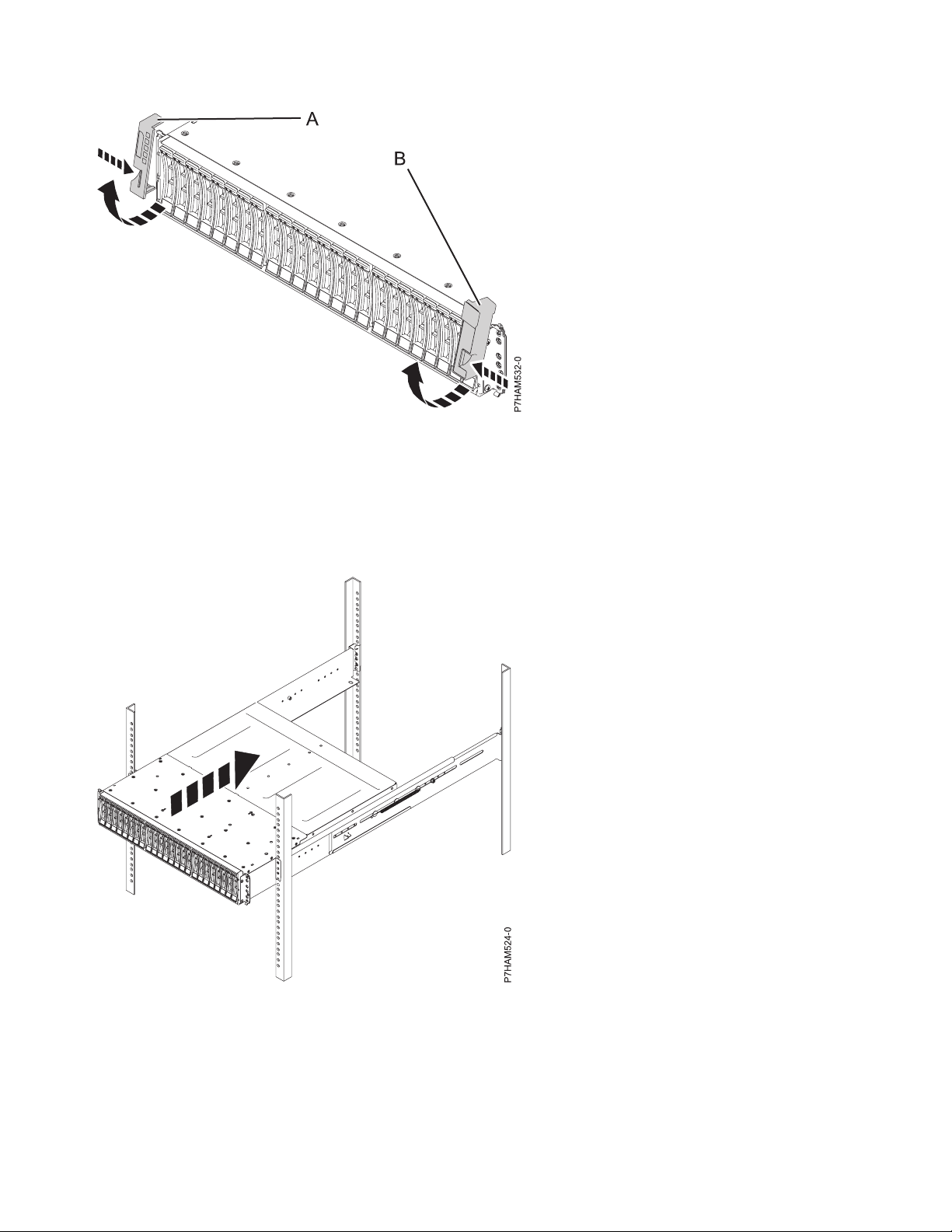
Figure 7. Removing the side covers
4. Using two people, lift the enclosure and position it over the front of the rails.
Attention: Two people are required to safely lift the enclosure. Using fewer than two people to lift
the enclosure can result in injury.
5. Slide the disk drive enclosure into the rack cabinet.
Figure 8. Sliding the disk drive enclosure into the rack
6. Secure the front of the disk drive enclosure to the rack flanges with one M5 screw (C) in the bottom
open holes in each bracket.
8 Power Systems: Installing the 5887 disk drive enclosure
Page 23

Figure 9. Securing the front of the disk drive enclosure to the rack
Optional: Install disk drives in the 5887 disk drive enclosure
Learn about the disk drives and details on how to install them.
To install disk drives, complete the following steps:
1. Ensure that you have the electrostatic discharge (ESD) wrist strap attached. If not, attach it now.
2. Remove the drive from the static-protective package.
Attention: Drives are fragile. Handle with care.
3. With the handle in the unlocked position, support the bottom of the disk drive as you align it with
the guide rails in the disk drive enclosure. See Figure 10 on page 10
Installing the 5887 disk drive enclosure or setting up a preinstalled 5887 disk drive enclosure 9
Page 24
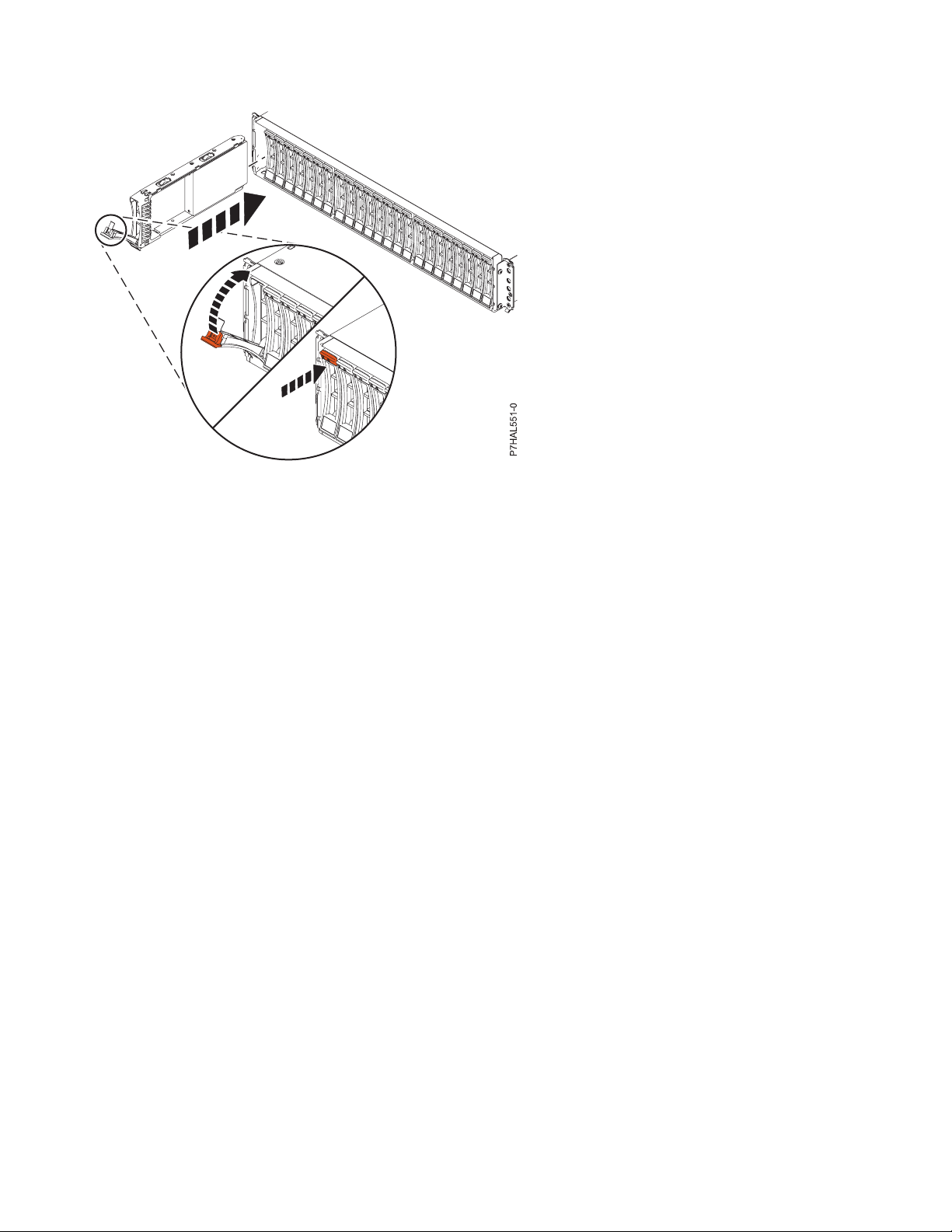
Figure 10. Installing a disk drive in the disk drive enclosure
Note: Do not hold the disk drive only by the handle.
4. Slide the disk unit into the disk drive enclosure until the drive stops.
5. Rotate the handle (A) to the locked position.
6. If you are installing more than one drive, repeat the steps in this procedure until all drives are
installed.
7. Review the following information that is related to connecting this device:
The SAS disk drive enclosure can hold up to 24 disk drives. The enclosure can be split logically into
one, two, or four independent groups.
The SAS disk drive enclosure supports the following operating systems:
v AIX
v IBM i
v Linux
v VIOS
If you are planning to configure RAID arrays, ensure that you have the minimum number of available
disks for each RAID level:
RAID 0
Minimum of one drive per array
RAID 5
Minimum of three drives per array
RAID 6
Minimum of four drives per array
RAID 10
Minimum of two drives per array
Connecting the 5887 disk drive enclosure to your system
Learn how to connect the 5887 disk drive enclosure to your system.
To connect the 5887 disk drive enclosure to a system with support for a serial-attached SCSI (SAS) disk
enclosure, complete the following steps.
10 Power Systems: Installing the 5887 disk drive enclosure
Page 25

For more information about SAS cabling and cabling configurations, see Serial-attached SCSI cable
planning (http://www.ibm.com/support/knowledgecenter/POWER8/p8had/p8had_sascabling.htm).
1. Ensure that you have the electrostatic discharge (ESD) wrist strap attached. If not, attach it now.
2. Confirm the factory-set mode of the enclosure by using information that is printed on stickers at the
rear of the enclosure. Stickers are attached to the lower-left shelf of the chassis (A) and the center
support between the enclosure services manager modules (B). The stickers indicate whether the
enclosure is set to mode 1, mode 2, or mode 4. For details, see Figure 11.
Figure 11. Mode sticker locations at the rear of the 5887 disk drive enclosure
3. Ensure that all adapters that you need to connect to the 5887 disk drive enclosure are installed in the
system or expansion unit. If the adapters are not installed, complete the adapter installation
procedure for your system or expansion unit before you continue with this task.
4. If the system requires an internal cable to be installed to produce an external SAS port for connection
with the enclosure, confirm that the installation was completed.
Remember: When you install or confirm the use of an external SAS port, record the location of the
external SAS port on the system. Later in this procedure, you are instructed to install the external
SAS cable to this system connector location.
5. Determine the configuration that you will use to cable the SAS adapter to the 5887 disk drive
enclosure. The following list shows some of the common connections, but not all possible connection
options. For more configuration options, see Planning for serial-attached SCSI cables
(http://www.ibm.com/support/knowledgecenter/POWER8/p8had/p8had_sascabling.htm).
v A mode 1 connection of one 5887 disk drive enclosure by using a YO cable to a single SAS
adapter.
v A mode 1 connection of two 5887 disk drive enclosures by using YO cables to a single SAS
adapter.
v A mode 1 connection of one 5887 disk drive enclosure by using YO cables to a SAS adapter pair.
v A mode 1 connection of two 5887 disk drive enclosures by using YO cables to a SAS adapter pair.
v A mode 2 connection of one 5887 disk drive enclosure by using YO cables to two independent
SAS adapters.
v A mode 2 connection of one 5887 disk drive enclosure by using X cables to two SAS adapter pairs.
v A mode 4 connection of one 5887 disk drive enclosure by using X cables to four independent SAS
adapters.
Installing the 5887 disk drive enclosure or setting up a preinstalled 5887 disk drive enclosure 11
Page 26

6. Locate the connection for each adapter for which you are using an external SAS cable to connect the
enclosure. Adapter cables attach to ports at the rear of the systems in which the adapters are
installed. To identify the SAS port location for the system in your configuration, see Connector
locations and select the appropriate model.
7. Select from the following options:
v If the server or expansion unit that you are attaching your 5887 disk drive enclosure to is powered
off, continue with step 12.
v If the system is powered on, you must do one of the following actions, depending on the
supported functions of your operating system:
– Unconfigure the adapters to which you are connecting the enclosure.
– Power off the adapters to which you are connecting the enclosure.
– Power off the logical partitions or systems that own the adapters to which you are connecting
the enclosure.
To do one of these required actions, continue with step 8.
8. Do the following conditions apply to your situation?
v Your system model does not support slot power control.
v Your adapters are not in an I/O enclosure that supports slot power control.
v You are unable to tolerate a temporary loss of access to other disk devices that might exist on the
same adapters.
– Yes: Power off the system or the logical partitions that own the adapters by completing the
steps in “Stopping a system or logical partition” on page 47. Then, continue with step 12.
– No: Continue with step 9.
9. Select from the following options:
v If you can unconfigure the SAS adapters, go to step 10.
v If you can not unconfigure the SAS adapters, you will need to power off the SAS adapters. Go to
step 11.
10. To unconfigure the SAS adapters, complete these steps:
a. Unconfigure the SAS adapters.
b. Ensure that you have the electrostatic discharge (ESD) wrist strap attached. If not, attach it now.
c. Connect the SAS cables from the enclosure to the SAS adapters.
d. Reconfigure the SAS adapters.
e. Continue with step 12.
11. To power off the SAS adapters, complete these steps:
a. Power off the SAS adapters.
b. Ensure that you have the electrostatic discharge (ESD) wrist strap attached. If not, attach it now.
c. Connect the SAS cables from the enclosure to the SAS adapters.
d. Power on the SAS adapters.
e. Configure the SAS adapters and devices.
f. Continue with step 12.
12. Choose one of the following options to cable the SAS adapter:
Note: The configuration figures show the use of adapters to represent the external server or
expansion unit connections. The adapter can represent one of the following connection types:
v The external port of an adapter that you confirmed in step 3 on page 11.
v The external port of an internal adapter cable that you confirmed in step 4 on page 11.
Note: Adapters are cabled to the enclosure by using ports at the rear of the enclosure. To learn about
the enclosure ports that are used in the following options, see Connector locations.
12 Power Systems: Installing the 5887 disk drive enclosure
Page 27

v To complete a mode 1 connection of one 5887 disk drive enclosure by using a YO cable to a single
SAS adapter, go to step 13.
v To complete a mode 1 connection of two 5887 disk drive enclosures by using YO cables to a single
SAS adapter, go to step 14.
v To complete a mode 1 connection of one 5887 disk drive enclosure by using YO cables to a SAS
adapter pair, go to step 15 on page 14.
v To complete a mode 1 connection of two 5887 disk drive enclosures by using YO cables to a SAS
adapter pair, go to step 16 on page 15.
v To complete a mode 2 connection of one 5887 disk drive enclosure by using YO cables to two
independent SAS adapters, go to step 17 on page 16.
v To complete a mode 2 connection of one 5887 disk drive enclosure by using X cables to two SAS
adapter pairs, go to step 18 on page 17.
v To complete a mode 4 connection of one 5887 disk drive enclosure by using X cables to four
independent SAS adapters, go to step 19 on page 18.
If your SAS configuration requirements are not supported by any of these options, go to step 20 on
page 20.
13. Perform the mode 1 connection of one enclosure (A) by using a YO cable (B) to a single SAS adapter
(C). See Figure 12.
Note: The single SAS adapter (C) has access to all 24 drive bays.
Figure 12. Mode 1 connection of one 5887 disk drive enclosure by using a YO cable to a single SAS adapter
Continue with “Connecting cables, power cords, and installing covers” on page 20.
14. Perform the mode 1 connection of two enclosures (A and B) by using YO cables (C and D) to a
single SAS adapter (E). See Figure 13 on page 14.
Note: The single SAS adapter (E) has access to all 48 drive bays.
Installing the 5887 disk drive enclosure or setting up a preinstalled 5887 disk drive enclosure 13
Page 28
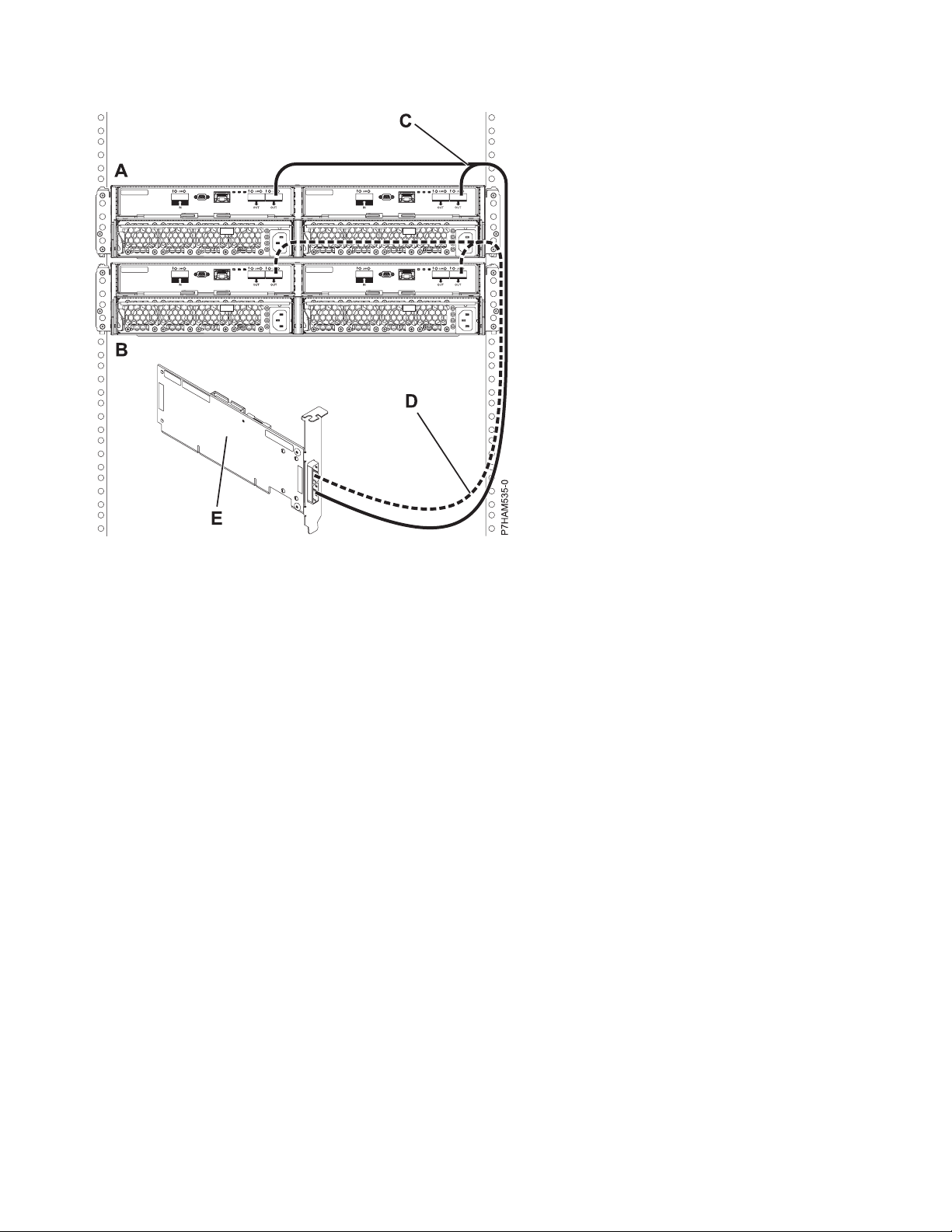
Figure 13. Mode 1 connection of two 5887 disk drive enclosures by using YO cables to a single SAS adapter
Continue with “Connecting cables, power cords, and installing covers” on page 20.
15. Perform the mode 1 connection of one enclosure (A) by using YO cables (B) to a SAS adapter pair
(C). See Figure 14 on page 15.
Notes:
v Each adapter in the SAS adapter pair (C) has access to the other adapter and to all 24 drive bays.
v If 6 Gb SAS adapters are being used, they must be cabled by using 6 Gb SAS cables.
v For SAS adapter pairs, you can attach the cables to any adapter port when you use the same port
in both adapters.
14 Power Systems: Installing the 5887 disk drive enclosure
Page 29

Figure 14. Mode 1 connection of one 5887 disk drive enclosure by using YO cables to a SAS adapter pair
Continue with “Connecting cables, power cords, and installing covers” on page 20.
16. Perform the mode 1 connection of two enclosures (A and B) by using YO cables (C and D) to a SAS
adapter pair (E). See Figure 15 on page 16.
Notes:
v Each adapter in the SAS adapter pair (C) has access to the other adapter and to all 48 drive bays.
v If 6 Gb SAS adapters are being used, they must be cabled by using 6 Gb SAS cables.
v For SAS adapter pairs, you can attach the cables to any adapter port when you use the same port
in both adapters.
Installing the 5887 disk drive enclosure or setting up a preinstalled 5887 disk drive enclosure 15
Page 30

Figure 15. Mode 1 connection of two 5887 disk drive enclosures by using YO cables to a SAS adapter pair
Continue with “Connecting cables, power cords, and installing covers” on page 20.
17. Perform the mode 2 connection of one enclosure (A) by using YO cables (B) to two independent SAS
adapters. See Figure 16 on page 17.
Notes:
v Independent SAS adapter 1 (C) does not have access to the other independent adapter and has
access only to drive bays D1 - D12.
v Independent SAS adapter 2 (D) does not have access to the other independent adapter and has
access only to drive bays D13 - D24.
16 Power Systems: Installing the 5887 disk drive enclosure
Page 31

Figure 16. Mode 2 connection of one 5887 disk drive enclosure by using YO cables to two independent SAS adapters
Continue with “Connecting cables, power cords, and installing covers” on page 20.
18. Perform the mode 2 connection of one enclosure (A) by using X cables (B) to two SAS adapter pairs.
See Figure 17 on page 18.
Notes:
v Each adapter in the SAS adapter pair 1 (C) has access to the other adapter and to drive bays D1 -
D12.
v Each adapter in the SAS adapter pair 2 (D) has access to the other adapter and to drive bays D13 -
D24.
v If 6 Gb SAS adapters are being used, they must be cabled by using 6 Gb SAS cables.
v For SAS adapter pairs, you can attach the cables to any adapter port when you use the same port
in both adapters.
Installing the 5887 disk drive enclosure or setting up a preinstalled 5887 disk drive enclosure 17
Page 32

Figure 17. Mode 2 connection of one 5887 disk drive enclosure by using X cables to two SAS adapter pairs
Continue with “Connecting cables, power cords, and installing covers” on page 20.
19. Perform the mode 4 connection of one enclosure (A) by using X cables (B) to four independent SAS
adapters. See Figure 18 on page 19.
Note: Refer to Figure 19 on page 19 for examples of these connections.
v The cable that plugs into independent SAS adapter 1 (C) contains a label with the P1 identifier
(G). This adapter does not have access to any other independent adapter and has access only to
drive bays D1 - D6.
v The cable that plugs into independent SAS adapter 2 (D) contains a label with the P2 identifier
(G). This adapter does not have access to any other independent adapter and has access only to
drive bays D7 - D12.
v The cable that plugs into independent SAS adapter 3 (E) contains a label with the P1 identifier
(G). This adapter does not have access to any other independent adapter and has access only to
drive bays D13 - D18.
v The cable that plugs into independent SAS adapter 4 (F) contains a label with the P2 identifier
(G). This adapter does not have access to any other independent adapter and has access only to
drive bays D19 - D24.
18 Power Systems: Installing the 5887 disk drive enclosure
Page 33
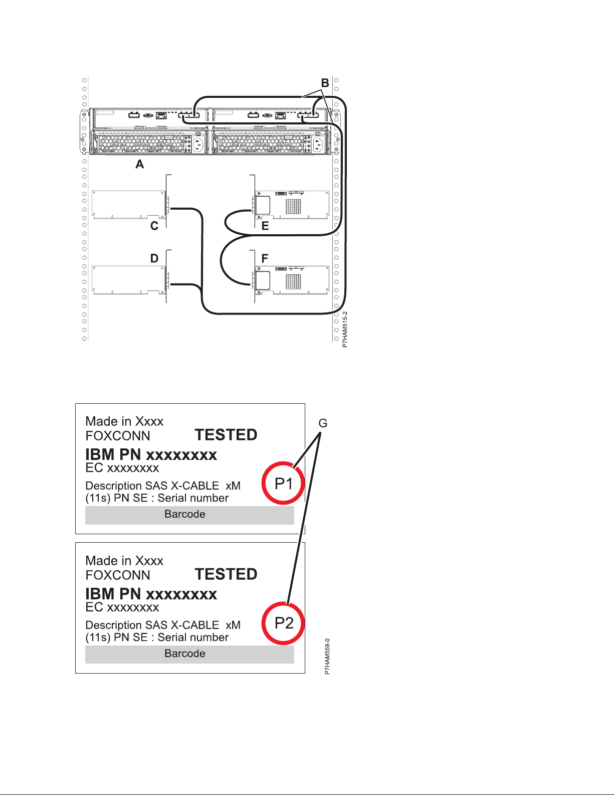
Figure 18. Mode 4 connection of one 5887 disk drive enclosure by using X cables to four independent SAS adapters
Figure 19. Labels for SAS adapter cables that show P1 and P2 identifiers
Installing the 5887 disk drive enclosure or setting up a preinstalled 5887 disk drive enclosure 19
Page 34

20. For more information about SAS cabling and cabling configurations, see Serial-attached SCSI cable
planning (http://www.ibm.com/support/knowledgecenter/POWER8/p8had/
p8had_sascabling.htm).
Connecting cables, power cords, and installing covers
Use this procedure to reconnect cables, power cords, and install the side covers.
To reconnect cables, attach power cords, and install the side covers, complete the following steps:
1. Ensure that you have the electrostatic discharge (ESD) wrist strap attached. If not, attach it now.
2. If your installation requirements included the removal of the SAS cables from the ESMs, review the
labeling that you completed and reinstall the cables.
Note: Do not apply power until instructed to do so.
3. Route the power cords through the power cord retention brackets (D) for strain relief, as shown in the
following figure.
Figure 20. Routing the power cords through the cord retention brackets
4. Connect the power cords to the left and right power supplies.
20 Power Systems: Installing the 5887 disk drive enclosure
Page 35

Figure 21. Connecting the power cords
5. Reinstall the left cover (A), which contains the service indicators, and the right cover (B).
6. Fit the slot on the top of the cover over the tab on the chassis flange.
7. Rotate the cover down until it snaps into place. Make sure that the inside surface of the cover is flush
with the chassis.
Figure 22. Attaching the side covers
8. Connect the other end of the power cables to the power distribution units (PDUs).
Installing the 5887 disk drive enclosure or setting up a preinstalled 5887 disk drive enclosure 21
Page 36

9. If you powered down either the system or the partition before you connected the disk drive enclosure
cables to it, power on the system or partition. If you did not power down the system or partition,
depending on the option you chose in the beginning of this procedure, you might need to reconfigure
the adapters.
Completing the 5887 disk drive enclosure installation
Learn how to complete the installation process.
To complete the installation process, complete the following steps:
1. To learn how to add the disk drives to the operating system, see the following information:
v To configure a disk drive or SSD for use by AIX, see Configuring a disk drive or solid-state drive
for use in an AIX system or AIX logical partition (http://www.ibm.com/support/
knowledgecenter/POWER8/p8hal/pxhal_configdrive_aix.htm).
v To configure a disk drive or SSD for use by IBM i, see Configuring a disk drive or solid-state drive
for use in an IBM i system or IBM i logical partition (http://www.ibm.com/support/
knowledgecenter/POWER8/p8hal/pxhal_configdrive_ibmi.htm).
v To configure a disk drive or SSD for use by Linux, see Configuring a disk drive or solid-state drive
for use in an Linux system or Linux logical partition (http://www.ibm.com/support/
knowledgecenter/POWER8/p8hal/pxhal_configdrive_linux.htm).
2. To verify that the system or logical partition recognizes the disk drive enclosure, see Verifying the
installed part (http://www.ibm.com/support/knowledgecenter/POWER8/p8haj/
pxhaj_hsmverify.htm).
3. You have completed the steps to install your 5887 disk drive enclosure. If you were directed here from
another procedure, return to that procedure now.
Setting up a preinstalled 5887 disk drive enclosure
Learn about the steps to set up a preinstalled 5887 disk drive enclosure.
Preparing to set up your preinstalled 5887 disk drive enclosure
Learn about the prerequisites for installing your 5887 disk drive enclosure and determine whether you
can install the enclosure concurrently
To prepare to set up your enclosure, complete the following steps:
1. Review the following information:
The SAS disk drive enclosure can hold up to 24 disk drives. The enclosure can be split logically into
one, two, or four independent groups. The SAS disk drive enclosure is supported by the following
operating systems:
v AIX
v IBM i
v Linux
v VIOS
2. Determine the level of software that you need to support the enclosure. For instructions, see the IBM
Prerequisite website (http://www-912.ibm.com/e_dir/eServerPrereq.nsf).
3. Ensure that you have the following items before you start your installation:
v #1 and #2 Phillips screwdriver
v Flat-head screwdriver
4. Determine whether you can add your 5887 disk drive enclosure concurrently by reviewing the
following information. You can add your expansion units concurrently (with the system powered on
and partitions active) if you have one of the following configurations:
22 Power Systems: Installing the 5887 disk drive enclosure
Page 37

v Your system is managed by an IBM Hardware Management Console (HMC).
v Your system is not managed by an HMC, but has only one partition, and that partition is running
the IBM i operating system.
Note: If you do not have one of these configurations, you must power off the system to add
enclosures.
Removing the shipping bracket on a preinstalled enclosure
Learn how to remove the shipping bracket that is used to brace the preinstalled enclosure.
There are three parts in the bracket assembly that is used to stabilize the 5887 disk drive enclosure during
shipment of the rack that contains the enclosure. The bracket assembly consists of a large bracket that
attaches to the rack frame and two smaller brackets that secure the two enclosure services manager (ESM)
units.
Prerequisite: A medium size screwdriver is required to complete this task.
To remove the shipping bracket, complete the following steps:
1. Attach the electrostatic discharge (ESD) wrist strap.
Attention:
v Attach an electrostatic discharge (ESD) wrist strap to an unpainted metal surface of your hardware
to prevent the electrostatic discharge from damaging your hardware.
v When using an ESD wrist strap, follow all electrical safety procedures. An ESD wrist strap is used
for static control. It does not increase or decrease your risk of receiving electric shock when using
or working on electrical equipment.
v If you do not have an ESD wrist strap, just prior to removing the product from ESD packaging and
installing or replacing hardware, touch an unpainted metal surface of the system for a minimum of
5 seconds.
2. To clear the shipping bracket installation area of cables and cords, complete the following steps:
a. Find the slotted opening in the small front bracket (A) below the left enclosure services manager
(ESM) and loosen the power supply cord (B) that is visible in the opening.
b. Carefully pull up the power supply cord through the small front bracket opening.
c. After you remove the connector end of the power cord from the opening (C), hang the loose
length of cable to one side so that it does not interfere with your workspace in the shipping
bracket installation area.
d. Using the same technique, remove and hang the right power supply cord. Do not disconnect or
detach the power supply cords from their attachments to the rack or to other cables.
Installing the 5887 disk drive enclosure or setting up a preinstalled 5887 disk drive enclosure 23
Page 38

Figure 23. Removing the power supply cords from their shipping position
3. To remove the small and large brackets, complete the following steps:
a. Loosen the two thumbscrews (A) on the small front brackets below the ESM units. Remove the
brackets by lifting them up and away from the ESM units.
24 Power Systems: Installing the 5887 disk drive enclosure
Page 39

Figure 24. Removing the small front brackets
b. Using a screwdriver, remove the screw that attaches the large bracket to the left flange of the rack
frame. Then, remove the screw that attaches the bracket to right flange.
Note: Keep the screws that you remove for later in the procedure.
Installing the 5887 disk drive enclosure or setting up a preinstalled 5887 disk drive enclosure 25
Page 40

Figure 25. Removing the screws from the bracket and rack flanges
c. Slide the large bracket toward the rear of the rack. Lift the bracket with two hands to remove it
from the side rails.
Tip: Save all of the brackets that you remove for future reinstallation and for shipping of the
enclosure that might be required.
26 Power Systems: Installing the 5887 disk drive enclosure
Page 41

Figure 26. Removing the shipping bracket
d. Reinstall the screws that you removed by inserting them into the same holes in the rack frame and
side rails from which you removed them. Tighten the screws with a screwdriver.
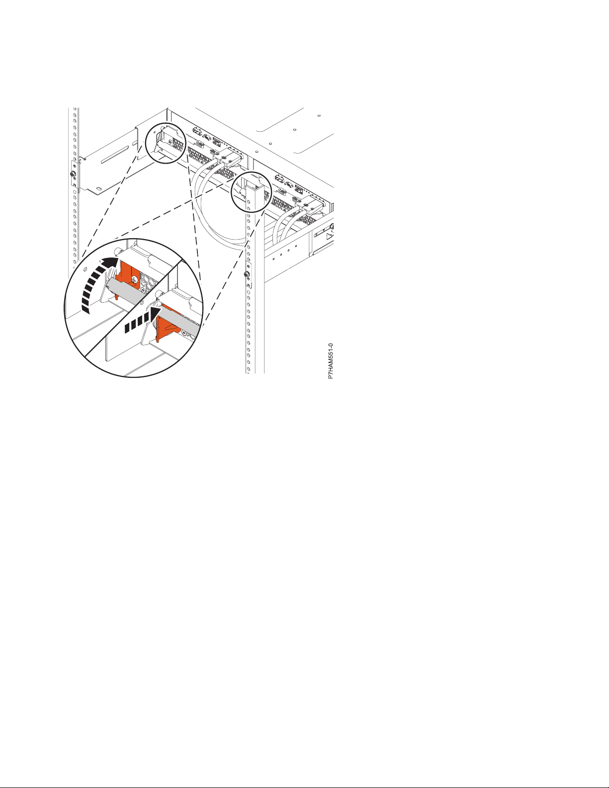
4. To dock and secure the ESM units, complete the following steps:
a. Moving one ESM at a time, slide the unit approximately 75 mm (3 in) toward the chassis.
b. For one ESM at a time, place your forefingers under the release levers and pinch the terracotta
lever tips. Release the levers and swing them into their fully open position.
Installing the 5887 disk drive enclosure or setting up a preinstalled 5887 disk drive enclosure 27
Page 42
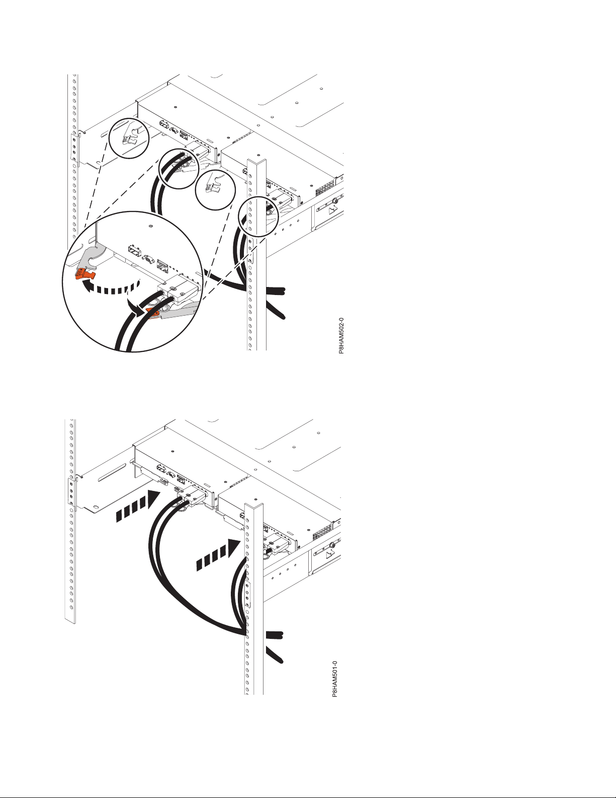
Figure 27. Opening the ESM release levers
c. Moving one ESM at a time, slide the unit into the chassis until it stops.
Figure 28. Docking the ESM units
28 Power Systems: Installing the 5887 disk drive enclosure
Page 43

d. For one ESM at a time, place your thumbs on the tips of the terracotta ESM levers and swing the
levers into their fully closed and latched position.
Figure 29. Closing the ESM release levers
5. To dock and secure the power supplies, complete the following steps:
a. Moving one power supply at a time, slide the unit approximately 75 mm (3 in) away from the
chassis.
Installing the 5887 disk drive enclosure or setting up a preinstalled 5887 disk drive enclosure 29
Page 44
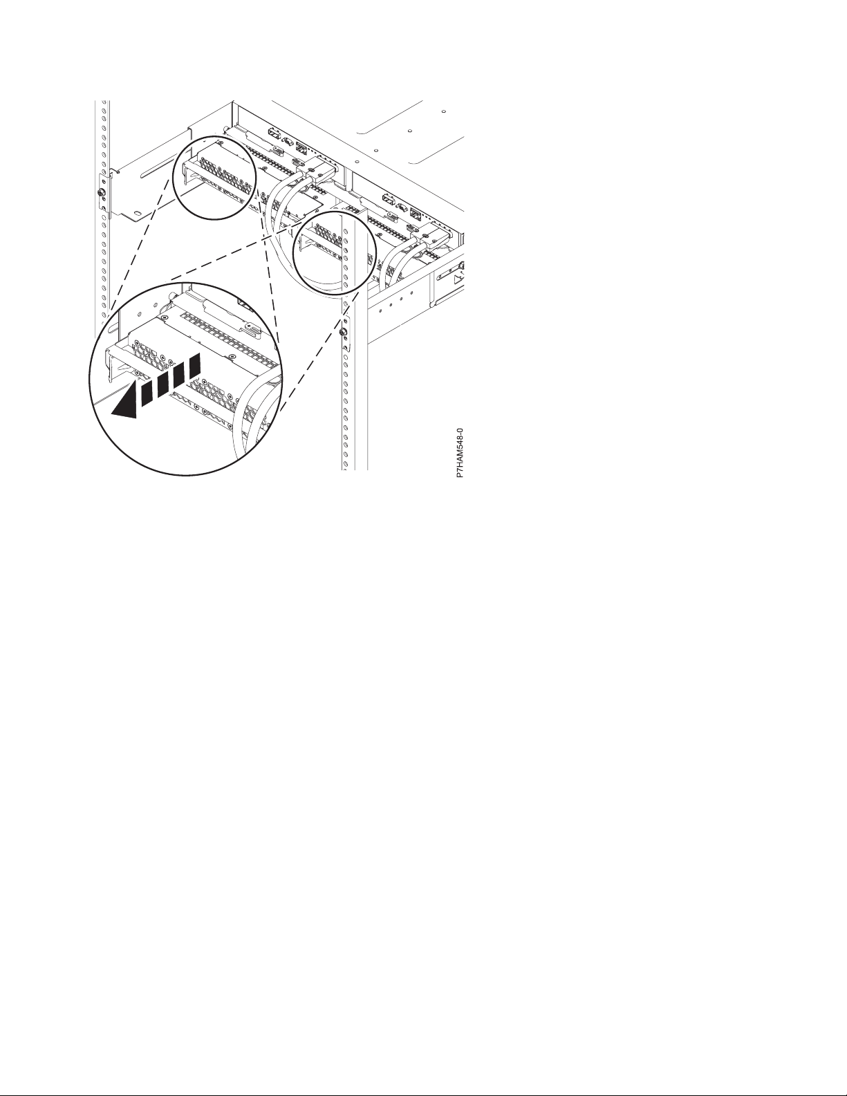
Figure 30. Sliding the power supplies toward the chassis
b. For one power supply at a time, rest your right thumb on the terracotta release latch beside the
unit handle and your fingertips on the handle. In one motion, squeeze the release latch to the right
and swing the handle down into its fully open position.
30 Power Systems: Installing the 5887 disk drive enclosure
Page 45
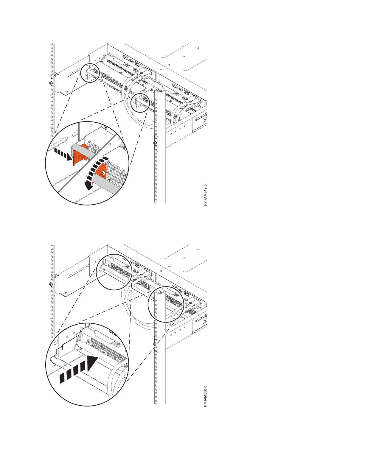
Figure 31. Opening the power supply release handle
c. Moving one power supply at a time, slide the unit into the chassis until it stops.
Figure 32. Docking the power supplies
Installing the 5887 disk drive enclosure or setting up a preinstalled 5887 disk drive enclosure 31
Page 46
d. Moving one power supply at a time, swing the unit handle up and into its fully closed position on
the release latch.
Figure 33. Closing the power supply release handle
Optional: Install disk drives in the preinstalled 5887 disk drive enclosure
Learn about the disk drives and details on how to install them.
To install disk drives, complete the following steps:
1. Ensure that you have the electrostatic discharge (ESD) wrist strap attached. If not, attach it now.
2. Remove the drive from the static-protective package.
Attention: Drives are fragile. Handle with care.
3. With the handle in the unlocked position, support the bottom of the disk drive as you align it with
the guide rails in the disk drive enclosure. For an example, see Figure 34 on page 33.
32 Power Systems: Installing the 5887 disk drive enclosure
Page 47
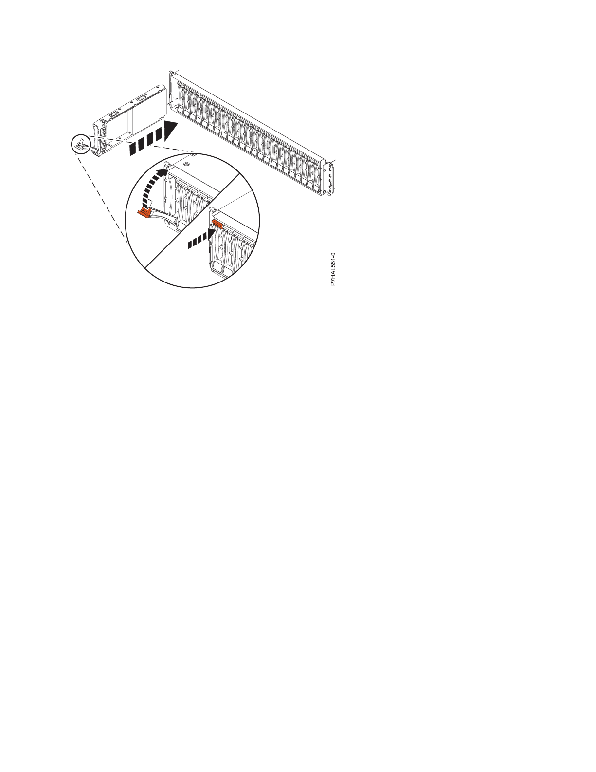
Figure 34. Installing a disk drive in the disk drive enclosure
Note: Do not hold the disk drive only by the handle.
4. Slide the disk unit into the disk drive enclosure until the drive stops.
5. Rotate the handle (A) to the locked position.
6. If you are installing more than one drive, repeat the steps in this procedure until all drives are
installed.
7. Review the following information that is related to connecting this device:
The SAS disk drive enclosure can hold up to 24 disk drives. The enclosure can be split logically into
one, two, or four independent groups.
The SAS disk drive enclosure supports the following operating systems:
v AIX
v IBM i
v Linux
v VIOS
If you are planning to configure RAID arrays, ensure that you have the minimum number of available
disks for each RAID level:
RAID 0
Minimum of one drive per array
RAID 5
Minimum of three drives per array
RAID 6
Minimum of four drives per array
RAID 10
Minimum of two drives per array
Connecting the preinstalled 5887 disk drive enclosure to your system
Learn how to connect the 5887 disk drive enclosure to your system.
To connect the 5887 disk drive enclosure to a system with support for a serial-attached SCSI (SAS) disk
enclosure, complete the following steps.
Installing the 5887 disk drive enclosure or setting up a preinstalled 5887 disk drive enclosure 33
Page 48

For more information about SAS cabling and cabling configurations, see Serial-attached SCSI cable
planning (http://www.ibm.com/support/knowledgecenter/POWER8/p8had/p8had_sascabling.htm).
1. Ensure that you have the electrostatic discharge (ESD) wrist strap attached. If not, attach it now.
2. Confirm the factory-set mode of the enclosure by using information that is printed on stickers at the
rear of the enclosure. Stickers are attached to the lower-left shelf of the chassis (A) and the center
support between the enclosure services manager modules (B). The stickers indicate whether the
enclosure is set to mode 1, mode 2, or mode 4. For details, see Figure 35.
Figure 35. Mode sticker locations at the rear of the 5887 disk drive enclosure
3. Ensure that all adapters that you need to connect to the 5887 disk drive enclosure are installed in the
system or expansion unit. If the adapters are not installed, complete the adapter installation
procedure for your system or expansion unit before you continue with this task.
4. If the system requires an internal cable to be installed to produce an external SAS port for connection
with the enclosure, confirm that the installation was completed.
Remember: When you install or confirm the use of an external SAS port, record the location of the
external SAS port on the system. Later in this procedure, you are instructed to install the external
SAS cable to this system connector location.
5. Determine the configuration that you will use to cable the SAS adapter to the 5887 disk drive
enclosure. The following list shows some of the common connections, but not all possible connection
options. For more configuration options, see Planning for serial-attached SCSI cables
(http://www.ibm.com/support/knowledgecenter/POWER8/p8had/p8had_sascabling.htm).
v A mode 1 connection of one 5887 disk drive enclosure by using a YO cable to a single SAS
adapter.
v A mode 1 connection of two 5887 disk drive enclosures by using YO cables to a single SAS
adapter.
v A mode 1 connection of one 5887 disk drive enclosure by using YO cables to a SAS adapter pair.
v A mode 1 connection of two 5887 disk drive enclosures by using YO cables to a SAS adapter pair.
v A mode 2 connection of one 5887 disk drive enclosure by using YO cables to two independent
SAS adapters.
v A mode 2 connection of one 5887 disk drive enclosure by using X cables to two SAS adapter pairs.
v A mode 4 connection of one 5887 disk drive enclosure by using X cables to four independent SAS
adapters.
34 Power Systems: Installing the 5887 disk drive enclosure
Page 49

6. Locate the connection for each adapter for which you are using an external SAS cable to connect the
enclosure. Adapter cables attach to ports at the rear of the systems in which the adapters are
installed. To identify the SAS port location for the system in your configuration, see Connector
locations and select the appropriate model.
7. Select from the following options:
v If the system is not powered on, continue with step 12.
v If the system is powered on, you must do one of the following actions, depending on the
supported functions of your operating system:
– Unconfigure the adapters to which you are connecting the enclosure.
– Power off the adapters to which you are connecting the enclosure.
– Power off the logical partitions or systems that own the adapters to which you are connecting
the enclosure.
To do one of these required actions, continue with step 8.
8. Do the following conditions apply to your situation?
v Your system model does not support slot power control.
v Your adapters are not in an I/O enclosure that supports slot power control.
v You are unable to tolerate a temporary loss of access to other disk devices that might exist on the
same adapters.
– Yes: Power off the system or the logical partitions that own the adapters by completing the
steps in “Stopping a system or logical partition” on page 47. Then, continue with step 12.
– No: Continue with step 9.
9. Select from the following options:
v If you can unconfigure the SAS adapters, go to step 10.
v If you can not unconfigure the SAS adapters, you will need to power off the SAS adapters. Go to
step 11.
10. To unconfigure the SAS adapters, complete these steps:
a. Unconfigure the SAS adapters.
b. Ensure that you have the electrostatic discharge (ESD) wrist strap attached. If not, attach it now.
c. Connect the SAS cables from the enclosure to the SAS adapters.
d. Reconfigure the SAS adapters.
e. Continue with step 12.
11. To power off the SAS adapters, complete these steps:
a. Power off the SAS adapters.
b. Ensure that you have the electrostatic discharge (ESD) wrist strap attached. If not, attach it now.
c. Connect the SAS cables from the enclosure to the SAS adapters.
d. Power on the SAS adapters.
e. Configure the SAS adapters and devices.
f. Continue with step 12.
12. Choose one of the following options to cable the SAS adapter:
Note: The configuration figures show the use of adapters to represent the external server or
expansion unit connections. The adapter can represent one of the following connection types:
v The external port of an adapter that you confirmed in step 3 on page 34.
v The external port of an internal adapter cable that you confirmed in step 4 on page 34.
Note: Adapters are cabled to the enclosure by using ports at the rear of the enclosure. To learn about
the enclosure ports that are used in the following options, see Connector locations.
Installing the 5887 disk drive enclosure or setting up a preinstalled 5887 disk drive enclosure 35
Page 50

v To complete a mode 1 connection of one 5887 disk drive enclosure by using a YO cable to a single
SAS adapter, go to step 13.
v To complete a mode 1 connection of two 5887 disk drive enclosures by using YO cables to a single
SAS adapter, go to step 14.
v To complete a mode 1 connection of one 5887 disk drive enclosure by using YO cables to a SAS
adapter pair, go to step 15 on page 37.
v To complete a mode 1 connection of two 5887 disk drive enclosures by using YO cables to a SAS
adapter pair, go to step 16 on page 38.
v To complete a mode 2 connection of one 5887 disk drive enclosure by using YO cables to two
independent SAS adapters, go to step 17 on page 39.
v To complete a mode 2 connection of one 5887 disk drive enclosure by using X cables to two SAS
adapter pairs, go to step 18 on page 40.
v To complete a mode 4 connection of one 5887 disk drive enclosure by using X cables to four
independent SAS adapters, go to step 19 on page 41.
If your SAS configuration requirements are not supported by any of these options, go to step 20 on
page 43.
13. Perform the mode 1 connection of one enclosure (A) by using a YO cable (B) to a single SAS adapter
(C). See Figure 36.
Note: The single SAS adapter (C) has access to all 24 drive bays.
Figure 36. Mode 1 connection of one 5887 disk drive enclosure by using a YO cable to a single SAS adapter
Continue with “Connecting cables, power cords, and installing side covers on your preinstalled
enclosure” on page 43.
14. Perform the mode 1 connection of two enclosures (A and B) by using YO cables (C and D) to a
single SAS adapter (E). See Figure 37 on page 37.
36 Power Systems: Installing the 5887 disk drive enclosure
Page 51
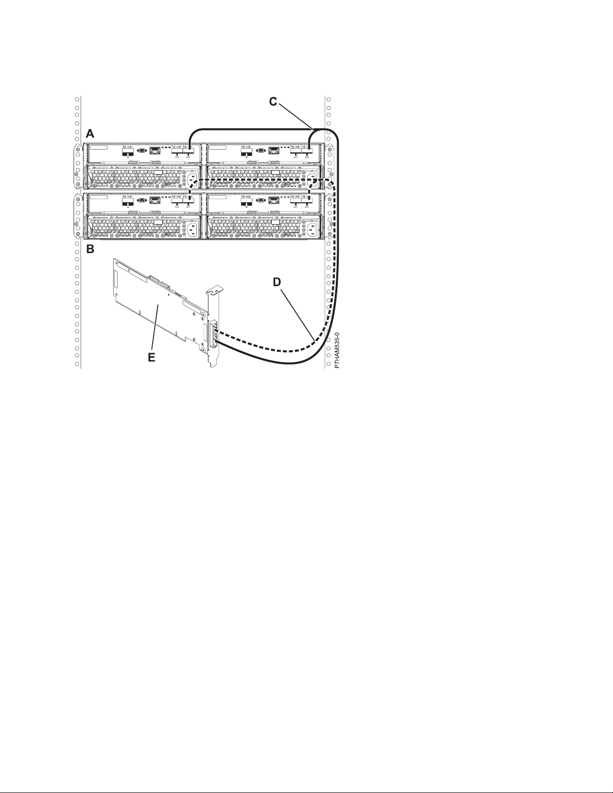
Note: The single SAS adapter (E) has access to all 48 drive bays.
Figure 37. Mode 1 connection of two 5887 disk drive enclosures by using YO cables to a single SAS adapter
Continue with “Connecting cables, power cords, and installing side covers on your preinstalled
enclosure” on page 43.
15. Perform the mode 1 connection of one enclosure (A) by using YO cables (B) to a SAS adapter pair
(C). See Figure 38 on page 38.
Notes:
v Each adapter in the SAS adapter pair (C) has access to the other adapter and to all 24 drive bays.
v If 6 Gb SAS adapters are being used, they must be cabled by using 6 Gb SAS cables.
v For SAS adapter pairs, you can attach the cables to any adapter port when you use the same port
in both adapters.
Installing the 5887 disk drive enclosure or setting up a preinstalled 5887 disk drive enclosure 37
Page 52

Figure 38. Mode 1 connection of one 5887 disk drive enclosure by using YO cables to a SAS adapter pair
Continue with “Connecting cables, power cords, and installing side covers on your preinstalled
enclosure” on page 43.
16. Perform the mode 1 connection of two enclosures (A and B) by using YO cables (C and D) to a SAS
adapter pair (E). See Figure 39 on page 39.
Notes:
v Each adapter in the SAS adapter pair (C) has access to the other adapter and to all 48 drive bays.
v If 6 Gb SAS adapters are being used, they must be cabled by using 6 Gb SAS cables.
v For SAS adapter pairs, you can attach the cables to any adapter port when you use the same port
in both adapters.
38 Power Systems: Installing the 5887 disk drive enclosure
Page 53

Figure 39. Mode 1 connection of two 5887 disk drive enclosures by using YO cables to a SAS adapter pair
Continue with “Connecting cables, power cords, and installing side covers on your preinstalled
enclosure” on page 43.
17. Perform the mode 2 connection of one enclosure (A) by using YO cables (B) to two independent SAS
adapters. See Figure 40 on page 40.
Notes:
v Independent SAS adapter 1 (C) does not have access to the other independent adapter and has
access only to drive bays D1 - D12.
v Independent SAS adapter 2 (D) does not have access to the other independent adapter and has
access only to drive bays D13 - D24.
Installing the 5887 disk drive enclosure or setting up a preinstalled 5887 disk drive enclosure 39
Page 54
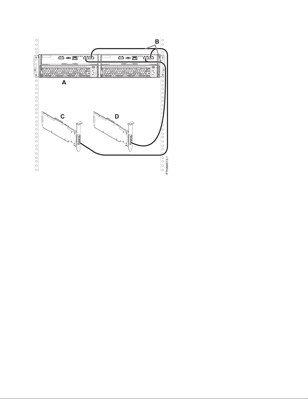
Figure 40. Mode 2 connection of one 5887 disk drive enclosure by using YO cables to two independent SAS adapters
Continue with “Connecting cables, power cords, and installing side covers on your preinstalled
enclosure” on page 43.
18. Perform the mode 2 connection of one enclosure (A) by using X cables (B) to two SAS adapter pairs.
See Figure 41 on page 41.
Notes:
v Each adapter in the SAS adapter pair 1 (C) has access to the other adapter and to drive bays D1 -
D12.
v Each adapter in the SAS adapter pair 2 (D) has access to the other adapter and to drive bays D13 -
D24.
v If 6 Gb SAS adapters are being used, they must be cabled by using 6 Gb SAS cables.
v For SAS adapter pairs, you can attach the cables to any adapter port when you use the same port
in both adapters.
40 Power Systems: Installing the 5887 disk drive enclosure
Page 55

Figure 41. Mode 2 connection of one 5887 disk drive enclosure by using X cables to two SAS adapter pairs
Continue with “Connecting cables, power cords, and installing side covers on your preinstalled
enclosure” on page 43.
19. Perform the mode 4 connection of one enclosure (A) by using X cables (B) to four independent SAS
adapters. See Figure 42 on page 42.
Installing the 5887 disk drive enclosure or setting up a preinstalled 5887 disk drive enclosure 41
Page 56

Figure 42. Mode 4 connection of one 5887 disk drive enclosure by using X cables to four independent SAS adapters
Note: Refer to Figure 43 on page 43 for examples of these connections:
v The cable that plugs into independent SAS adapter 1 (C) contains a label with the P1 identifier
(G). This adapter does not have access to any other independent adapter and has access only to
drive bays D1 - D6.
v The cable that plugs into independent SAS adapter 2 (D) contains a label with the P2 identifier
(G). This adapter does not have access to any other independent adapter and has access only to
drive bays D7 - D12.
v The cable that plugs into independent SAS adapter 3 (E) contains a label with the P1 identifier
(G). This adapter does not have access to any other independent adapter and has access only to
drive bays D13 - D18.
v The cable that plugs into independent SAS adapter 4 (F) contains a label with the P2 identifier
(G). This adapter does not have access to any other independent adapter and has access only to
drive bays D19 - D24.
42 Power Systems: Installing the 5887 disk drive enclosure
Page 57

Figure 43. Labels for SAS adapter cables that show P1 and P2 identifiers
20. For more information about SAS cabling and cabling configurations, see Serial-attached SCSI cable
planning (http://www.ibm.com/support/knowledgecenter/POWER8/p8had/
p8had_sascabling.htm).
Connecting cables, power cords, and installing side covers on your preinstalled enclosure
Use this procedure to reconnect cables, power cords, and install the side covers on your preinstalled disk
drive enclosure.
To reconnect cables, attach power cords, and install the side covers, complete the following steps:
1. Ensure that you have the electrostatic discharge (ESD) wrist strap attached. If not, attach it now.
2. If your installation requirements included the removal of the SAS cables from the ESMs, review the
labeling that you completed and reinstall the cables.
Note: Do not apply power until instructed to do so.
3. Reinstall the left cover (A), which contains the service indicators, and the right cover (B).
4. Fit the slot on the top of the cover over the tab on the chassis flange.
5. Rotate the cover down until it snaps into place. Make sure that the inside surface of the cover is flush
with the chassis.
Installing the 5887 disk drive enclosure or setting up a preinstalled 5887 disk drive enclosure 43
Page 58

Figure 44. Attaching the side covers
6. Route the power cords through the power cord retention brackets (D) for strain relief as shown in the
following figure. Connect the power cables and apply power to the disk drive enclosure.
Figure 45. Routing the power cords through the cord retention brackets
7. If you powered down either the system or the partition before you connected the disk drive enclosure
cables to it, power on the system or partition. If you did not power down the system or partition,
depending on the option you chose in the beginning of this procedure, you might need to reconfigure
the adapters.
Completing the 5887 disk drive enclosure installation
Learn how to complete the installation process.
To complete the installation process, complete the following steps:
1. To learn how to add the disk drives to the operating system, see the following information:
v To configure a disk drive or SSD for use by AIX, see Configuring a disk drive or solid-state drive
for use in an AIX system or AIX logical partition (http://www.ibm.com/support/
knowledgecenter/POWER8/p8hal/pxhal_configdrive_aix.htm).
v To configure a disk drive or SSD for use by IBM i, see Configuring a disk drive or solid-state drive
for use in an IBM i system or IBM i logical partition (http://www.ibm.com/support/
knowledgecenter/POWER8/p8hal/pxhal_configdrive_ibmi.htm).
44 Power Systems: Installing the 5887 disk drive enclosure
Page 59

v To configure a disk drive or SSD for use by Linux, see Configuring a disk drive or solid-state drive
for use in an Linux system or Linux logical partition (http://www.ibm.com/support/
knowledgecenter/POWER8/p8hal/pxhal_configdrive_linux.htm).
2. To verify that the system or logical partition recognizes the disk drive enclosure, see Verifying the
installed part (http://www.ibm.com/support/knowledgecenter/POWER8/p8haj/
pxhaj_hsmverify.htm).
3. You have completed the steps to install your 5887 disk drive enclosure. If you were directed here from
another procedure, return to that procedure now.
Installing the 5887 disk drive enclosure or setting up a preinstalled 5887 disk drive enclosure 45
Page 60

46 Power Systems: Installing the 5887 disk drive enclosure
Page 61

Reference information
Use the information in this section as needed to complete enclosure installation and configuration tasks.
Stopping a system or logical partition
Learn how to stop a system or logical partition as a part of a system upgrade or service action.
Attention: Using either the power-on button on the control panel or entering commands at the
Hardware Management Console (HMC) to stop the system can cause unpredictable results in the data
files. Also, the next time you start the system, it might take longer if all applications are not ended before
stopping the system.
To stop the system or logical partition, select the appropriate procedure.
Stopping a system that is not managed by an HMC
You might need to stop the system to complete another task. If your system is not managed by the
Hardware Management Console (HMC), use these instructions to stop the system by using the power
button or the Advanced System Management Interface (ASMI).
Before you stop the system, follow these steps:
1. Ensure that all jobs are completed and end all applications.
2. If a Virtual I/O Server (VIOS) logical partition is running, ensure that all clients are shut down or that
the clients have access to their devices by using an alternative method.
Stopping a system by using the control panel
You might need to stop the system to complete another task. If your system is not managed by the
Hardware Management Console (HMC), use these instructions to stop the system by using the power
button.
The following procedure describes how to stop a system that is not managed by the HMC.
1. Log in to the host partition as a user with the authority to run the shutdown or pwrdwnsys (Power
Down System) command.
2. At the command line, enter one of the following commands:
v If your system is running the AIX operating system, type shutdown.
v If your system is running the Linux operating system, type shutdown -h now.
v If your system is running the IBM i operating system, type PWRDWNSYS. If your system is partitioned,
use the PWRDWNSYS command to power down each of the secondary partitions. Then, use the
PWRDWNSYS command to power down the primary partition.
The command stops the operating system. The system power turns off, the power-on light begins to
slowly flash, and the system goes into a standby state.
3. Record the IPL type and the IPL mode from the control panel display to help you return the system
to this state when the installation or replacement procedure is completed.
4. Set the power switches of any devices that are connected to the system to off.
Stopping a system by using the ASMI
You might need to stop the system to complete another task. If your system is not managed by the
Hardware Management Console (HMC), use these instructions to stop the system by using the Advanced
System Management Interface (ASMI).
© Copyright IBM Corp. 2014, 2015 47
Page 62

To stop a system by using the ASMI, complete the following steps:
1. On the ASMI Welcome pane, specify your user ID and password, and click Log In.
2. In the navigation area, click Power/Restart Control > Power On/Off System. The power state of the
system is displayed.
3. Specify the settings as required and click Save setting and power off.
Stopping a system by using the HMC
You can use the Hardware Management Console (HMC) to stop the system or logical partition.
By default, the managed system is set to power off automatically when you shut down the last running
logical partition on the managed system. If you set the managed system properties on the HMC so that
the managed system does not power off automatically, you must use this procedure to power off your
managed system.
Attention: Ensure that you shut down the running logical partitions on the managed system before you
power off the managed system. Powering off the managed system without shutting down the logical
partitions first causes the logical partitions to shut down abnormally and can cause data loss. If you use a
Virtual I/O Server (VIOS) logical partition, ensure that all clients are shut down or that the clients have
access to their devices by using an alternative method.
To power off a managed system, you must be a member of one of the following roles:
v Super administrator
v Service representative
v Operator
v Product engineer
Note: If you are a product engineer, verify that the customer has shut down all active partitions and
has powered off the managed system. Continue with the procedure only after the status of the server
changes to Power Off.
Stopping a system by using the HMC Classic or HMC Enhanced interface
Learn how to stop a system by using the HMC Classic or HMC Enhanced interface.
To stop the system or logical partition by using the HMC Classic or HMC Enhanced interface, complete
the following steps:
1. In the navigation area, click Systems Management > Servers.
2. In the content pane, select the managed system.
3. In the Tasks area, click Operations > Power Off.
4. Select the appropriate power-off mode and click OK.
Related information:
Shutting down and restarting logical partitions
Stopping a system by using the HMC Enhanced + Tech Preview (Pre-GA) or HMC Enhanced+ interface
Learn how to stop a system by using the HMC Enhanced + Tech Preview (Pre-GA) or HMC Enhanced+
interface.
To stop the system or logical partition by using the HMC Enhanced + Tech Preview (Pre-GA) or HMC
Enhanced+ interface, complete the following steps:
1. You must deactivate all the active logical partitions before powering off the system. To deactivate
logical partitions for a specific system, complete the following steps:
48 Power Systems: Installing the 5887 disk drive enclosure
Page 63

a. In the navigation area, click the Resources icon , and then click All Systems.
b. Click the system name for which you want to deactivate partitions.
c. In the navigation area, click Partitions > View Partitions.
d. Select the logical partitions that you want to deactivate.
e. In the content pane, click Actions > Deactivate.
f. Click OK.
2. To power off the system, complete the following steps:
a. In the navigation area, click the Resources icon
b. Select the system that you want to power off.
c. In the content pane, click Actions > View All Actions > Power Off.
d. Click OK.
, and then click All Systems.
Stopping an IBM PowerKVM system
You can use the Intelligent Platform Management Interface (IPMI) to stop an IBM PowerKVM system.
To stop an IBM PowerKVM system, complete the following steps:
1. Log in to the host as a root user or with sudo authority.
2. To power off each of the guests, complete the following steps.
a. To obtain a list of all guests, type virsh list.
b. For each guest in the list, type virsh shutdown domain name or type virsh shutdown domain ID.
Note:
Type virsh list to verify whether all the guests are powered off. If any guest is not powered off,
type virsh destroy domain name or type virsh destroy domain ID to power off the guest.
3. Run the ipmitool -I lanplus -H FSP IP -P ipmipassword chassis power off command from a remote
system.
Starting the system or logical partition
Learn how to start a system or logical partition after performing a service action or system upgrade.
Starting a system that is not managed by an HMC
You can use the power button or the Advanced System Management Interface (ASMI) to start a system
that is not managed by a Hardware Management Console (HMC).
Starting a system by using the control panel
You can use the power button on the control panel to start a system that is not managed by a Hardware
Management Console (HMC).
To start a system that by using the control panel, complete the following steps:
1. Open the front rack door, if necessary.
2. Before you press the power button on the control panel, ensure that power is connected to the system
unit as follows:
v All system power cables are connected to a power source.
v The power LED, as shown in the following figure, is slowly flashing.
Reference information 49
Page 64

v The top of the display, as shown in the following figure, shows 01 V=F.
3. Press the power button (A), as shown in the following figure, on the control panel.
ABCDE
Front View
Top View
F
G
HI
Figure 46. Control panel
v A: Power-on button
– A constant light indicates full system power to the unit.
– A flashing light indicates standby power to the unit.
– There is approximately a 30-second transition period from the time the power-on button is
pressed to when the power LED goes from flashing to solid. During the transition period, the
LED might flash faster.
v B: Enclosure identify light
– A constant light indicates the identify state, which is used to identify a part.
– No light indicates that the system is operating normally.
v C: System information light
– No light indicates that the system is operating normally.
– Light on indicates that the system requires attention.
v D: Enclosure fault roll-up light
– A constant light indicates a fault in the enclosure.
– No light indicates that the system is operating normally.
v E: Eject button
v F: Function/Data display
v G: Pinhole reset button
v H: Decrement button
v I: Enter button
v J: Increment button
4. Observe the following aspects after pressing the power button:
J
P8HB5500-1
50 Power Systems: Installing the 5887 disk drive enclosure
Page 65

v The power-on light begins to flash faster.
v The system cooling fans are activated after approximately 30 seconds and begin to accelerate to
operating speed.
v Progress indicators, also referred to as checkpoints, appear on the control panel display while the
system is being started. The power-on light on the control panel stops flashing and remains on,
indicating that the system power is on.
Tip: If pressing the power button does not start the system, then contact your next level of support or
your service provider.
Starting a system by using the ASMI
You can use the Advanced System Management Interface (ASMI) to start a system that is not managed
by a Hardware Management Console (HMC).
To start a system by using the ASMI, complete the following steps:
1. On the ASMI Welcome pane, specify your user ID and password, and click Log In.
2. In the navigation area, click Power/Restart Control > Power On/Off System. The power state of the
system is displayed.
3. Specify the settings as required and click Save setting and power on.
Starting a system or logical partition by using the HMC
You can use the Hardware Management Console (HMC) to start the system or logical partition after the
required cables are installed and the power cables are connected to a power source.
Starting a system or logical partition by using the HMC Classic or HMC Enhanced interface
Learn how to start a system or logical partition by using the HMC Classic or HMC Enhanced interface.
To start the system by using the HMC Classic or HMC Enhanced interface, complete the following steps:
1. Verify that the logical partition start policy is set to User-Initiated by completing the following steps:
a. In the navigation area, expand Systems Management > Servers.
b. In the content pane, select the managed system.
c. In the Tasks area, click Properties.
d. Click the Power-On Parameters tab. Ensure that the Partition start policy field is set to
User-Initiated.
2. Power on the managed system by completing the following steps:
a. In the navigation area, expand Systems Management > Servers.
b. In the content pane, select the managed system.
c. Click Operations > Power on.
d. Select the power-on option and click OK.
Starting a system or logical partition by using the HMC Enhanced + Tech Preview (Pre-GA) or HMC Enhanced+ interface
Learn how to start a system or logical partition by using the HMC Enhanced + Tech Preview (Pre-GA) or
HMC Enhanced+ interface.
To start a system or logical partition by using the HMC Enhanced + Tech Preview (Pre-GA) or HMC
Enhanced+ interface, complete the following steps:
1. To power on the managed system, complete the following steps:
Reference information 51
Page 66

a. In the navigation area, click the Resources icon , and then click All Systems.
b. Select the system that you want to power on.
c. In the content pane, click Actions > View All Actions > Power On.
d. Click OK.
2. To activate a logical partition, complete the following steps:
a. In the navigation area, click the Resources icon
b. Click the logical partition name that you want to activate.
c. In the navigation area, click Partition Actions > Operations > Activate.
d. Click OK.
3. To activate a logical partition for a specific system, complete the following steps:
a. In the navigation area, click the Resources icon
b. Click the system name in which you want to activate the logical partition.
c. In the navigation area, click Partitions > View Partitions.
d. Select logical partitions that you want to activate.
e. In the content pane, click Actions > Activate.
f. Click OK.
4. To verify that the logical partition start policy is set to User-Initiated, complete the following steps:
a. In the navigation area, click the Resources icon
b. Click the system name to view details.
c. In the navigation area, click Properties > Other Properties.
d. Click the Power-On Parameters tab. Ensure that the Partition start policy field is set to
User-Initiated.
, and then click All Partitions.
, and then click All Systems.
, and then click All Systems.
Starting an IBM PowerKVM system
You can use the Intelligent Platform Management Interface (IPMI) to start an IBM PowerKVM system.
To start an IBM PowerKVM system, run the ipmitool -I lanplus -H FSP IP -P ipmipassword chassis
power on command from a remote system.
Connector locations
Learn about connector locations for servers and enclosures and expansion units.
Enclosure and expansion unit connectors
Learn about connector locations for enclosures and expansion units.
52 Power Systems: Installing the 5887 disk drive enclosure
Page 67

Connector locations for the 5887 disk drive enclosure
Learn about connector locations for the 5887 disk drive enclosure.
Figure 47. Connector locations for the 5887 disk drive enclosure
Connector locations for the PCIe Gen3 I/O expansion drawer
Learn about connector locations for the PCIe Gen3 I/O expansion drawer (PCIe3 expansion drawer).
Figure 48. PCIe Gen3 I/O expansion drawer showing the PCIe3 6-slot fanout module
For more information about the PCIe3 expansion drawer locations, see PCIe Gen3 I/O expansion drawer
locations (http://www.ibm.com/support/knowledgecenter/POWER8/p8ecs/p8ecs_emx0_loccodes.htm).
Connector locations for POWER8 servers
Learn about connector locations for POWER8™servers.
Connector locations for the 8247-21L, 8247-22L, and 8284-22A systems
Learn about connector locations for the 8247-21L, 8247-22L, and 8284-22A systems.
The expanded function 8247-21L, 8247-22L, and 8284-22A servers provide cable connector locations via a
SAS port for disk drive enclosures.
Reference information 53
Page 68
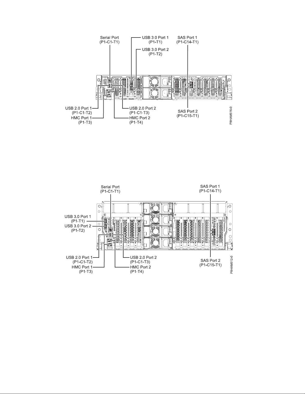
Figure 49. Connector locations for the expanded function 8247-21L, 8247-22L, and 8284-22A systems
Connector locations for the 8286-41A system
Learn about connector locations for the 8286-41A rack-mounted and stand-alone models.
The 8286-41A server provides cable connector locations via a SAS port for disk drive enclosures.
Figure 50. Connector locations for the rack-mounted 8286-41A (expanded function) system
54 Power Systems: Installing the 5887 disk drive enclosure
Page 69
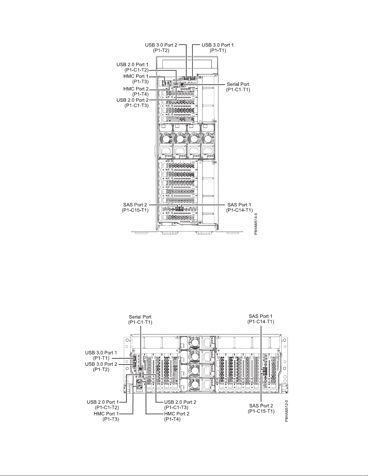
Figure 51. Connector locations for the stand-alone 8286-41A (expanded function) system
Connector locations for the 8286-42A system
Learn about connector locations for the 8286-42A rack-mounted models.
The 8286-42A (expanded function) server provides cable connector locations via a SAS port for disk drive
enclosures.
Figure 52. Connector locations for the 8286-42A (expanded function) system
Reference information 55
Page 70

Connector locations for the 8408-E8E system
Learn about connector locations for the 8408-E8E system.
The 8408-E8E server provides cable connector locations via a SAS port (P1-C5-T3) for disk drive
enclosures and cable ports (P1-C5-T1 and P1-C5-T2) for the PCIe3 expansion drawer.
Figure 53. Connector locations for an 8408-E8E system
Connector locations for the 9119-MHE and 9119-MME systems
Learn about connector locations for the 9119-MHE and 9119-MME systems.
The 9119-MHE and 9119-MME servers provide cable connector locations for the PCIe Gen3 I/O
expansion drawer.
56 Power Systems: Installing the 5887 disk drive enclosure
Page 71
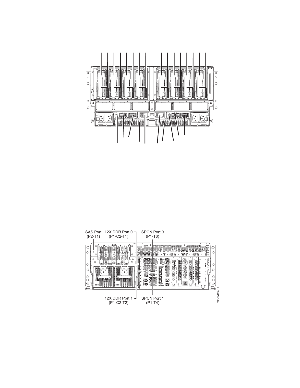
P1-C1
P1-C1-C1
P1-C2
P1-C2-C1
P1-C3
P1-C3-C1
P1-C4
P1-C4-C1
P1-C5
P1-C5-C1
P1-C6
P1-C6-C1
P1-C7
P1-C7-C1
P1-C8
P1-C8-C1
P1-T1 P1-T2
P1-C9
P1-T3
P1-C9-T1
P1-C9-T2
P1-C11
P1-T7
P1-T4
P1-T8
P1-T5 P1-T6
P1-C12
P1-C10
C10-T2
P1-C10-T1
P1-
Figure 54. Connector locations for the 9119-MHE and 9119-MME systems
Connector locations for POWER7 servers
Learn about connector locations for POWER7®servers.
Model 8202-E4B connector locations
Learn about connector locations on rack-mounted and stand-alone models.
P8ECS804-1
Figure 55. Model 8202-E4B connector locations on a rack-mounted model
Reference information 57
Page 72

Figure 56. Model 8202-E4B connector locations on a stand-alone model
Model 8202-E4C connector locations
Learn about connector locations on rack-mounted models.
The 8202-E4C server provides cable connector locations for the following enclosures:
v Support for expansion units, as shown in the following figure, is as follows:
– The card installed in the C1 slot can contain two 12X double data rate (DDR) cable ports. However,
the C1 slot cannot provide both 12X DDR and PCIe cable ports.
– The server contains a serial-attached SCSI (SAS) port.
v Support for disk drive enclosures, as shown in the following figure, is as follows:
– The server contains a SAS port.
v Support for PCIe storage enclosures, as shown in the following figure, is as follows:
– The card installed in the C1 slot can contain two PCIe cable ports. However, the C1 slot cannot
provide both PCIe and 12X DDR cable ports.
– The server contains a SAS port.
58 Power Systems: Installing the 5887 disk drive enclosure
Page 73

Figure 57. Model 8202-E4C connections for expansion units, disk drive enclosures, and PCIe storage enclosures
Model 8202-E4D connector locations
Learn about connector locations on rack-mounted models.
The 8202-E4D server provides cable connector locations for the following enclosures:
v Support for expansion units, as shown in the following figure, is as follows:
– The card installed in the C1 slot can contain two 12X double data rate (DDR) cable ports. However,
the C1 slot cannot provide both 12X DDR and PCIe cable ports.
– The server contains a serial-attached SCSI (SAS) port.
v Support for disk drive enclosures, as shown in the following figure, is as follows:
– The server contains a SAS port.
v Support for PCIe storage enclosures, as shown in the following figure, is as follows:
– The card installed in the C1 slot can contain two PCIe cable ports. However, the C1 slot cannot
provide both PCIe and 12X DDR cable ports.
– The server contains a SAS port.
Figure 58. Model 8202-E4D connections for expansion units, disk drive enclosures, and PCIe storage enclosures
Reference information 59
Page 74

Model 8205-E6B connector locations
Learn about connector locations on rack-mounted and stand-alone models.
Figure 59. Model 8205-E6B connector locations on a rack-mounted model
Figure 60. Model 8205-E6B connector locations on a stand-alone model
Model 8205-E6C connector locations
Learn about connector locations on rack-mounted models.
The 8205-E6C server provides cable connector locations for the following enclosures:
v Support for expansion units, as shown in the following figure, is as follows:
– The card installed in the C1 slot can contain two 12X double data rate (DDR) cable ports. However,
the C1 slot cannot provide both 12X DDR and PCIe cable ports.
60 Power Systems: Installing the 5887 disk drive enclosure
Page 75

– The card installed in the C8 slot can contain two 12X DDR cable ports. However, the C8 slot cannot
provide both 12X DDR and PCIe cable ports.
– The port card type installed in the C1 slot can differ from the port card type installed in the C8 slot.
– The server contains a serial-attached SCSI (SAS) port.
v Support for disk drive enclosures, as shown in the following figure, is as follows:
– The server contains a SAS port.
v Support for PCIe storage enclosures, as shown in the following figure, is as follows:
– The card installed in the C1 slot can contain two PCIe cable ports. However, the C1 slot cannot
provide both PCIe and 12X DDR cable ports.
– The card installed in the C8 slot can contain two PCIe cable ports. However, the C8 slot cannot
provide both PCIe and 12X DDR cable ports.
– The port card type installed in the C1 slot can differ from the port card type installed in the C8 slot.
– The server contains a SAS port.
Figure 61. Model 8205-E6C connections for expansion units, disk drive enclosures, and PCIe storage enclosures
Model 8205-E6D connector locations
Learn about connector locations on rack-mounted models.
The 8205-E6D server provides cable connector locations for the following enclosures:
v Support for expansion units, as shown in the following figure, is as follows:
– The card installed in the C1 slot can contain two 12X double data rate (DDR) cable ports. However,
the C1 slot cannot provide both 12X DDR and PCIe cable ports.
– The card installed in the C8 slot can contain two 12X DDR cable ports. However, the C8 slot cannot
provide both 12X DDR and PCIe cable ports.
– The port card type installed in the C1 slot can differ from the port card type installed in the C8 slot.
– The server contains a serial-attached SCSI (SAS) port.
v Support for disk drive enclosures, as shown in the following figure, is as follows:
– The server contains a SAS port.
v Support for PCIe storage enclosures, as shown in the following figure, is as follows:
– The card installed in the C1 slot can contain two PCIe cable ports. However, the C1 slot cannot
provide both PCIe and 12X DDR cable ports.
– The card installed in the C8 slot can contain two PCIe cable ports. However, the C8 slot cannot
provide both PCIe and 12X DDR cable ports.
– The port card type installed in the C1 slot can differ from the port card type installed in the C8 slot.
Reference information 61
Page 76
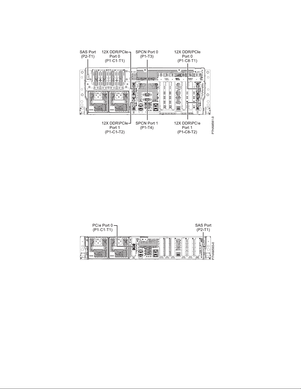
– The server contains a SAS port.
Figure 62. Model 8205-E6D connections for expansion units, disk drive enclosures, and PCIe storage enclosures
Model 8231-E1C connector locations
Learn about connector locations.
The 8231-E1C server provides cable connector locations for the following enclosures:
v Support for disk drive enclosures, as shown in the following figure, is as follows:
– The server contains a serial-attached SCSI (SAS) port.
v Support for PCIe storage enclosures, as shown in the following figure, is as follows:
– The card installed in the C1 slot can contain one PCIe cable port.
– The server contains a SAS port.
Figure 63. Model 8231-E1C connections for disk drive enclosures and PCIe storage enclosures
Model 8231-E1D or 8268-E1D connector locations
Learn about connector locations.
The 8231-E1D or 8268-E1D servers provides cable connector locations for the following enclosures:
v Support for disk drive enclosures, as shown in the following figure, is as follows:
– The server contains a serial-attached SCSI (SAS) port.
v Support for PCIe storage enclosures, as shown in the following figure, is as follows:
– The card installed in the C1 slot can contain one PCIe cable port.
– The server contains a SAS port.
62 Power Systems: Installing the 5887 disk drive enclosure
Page 77

Figure 64. Model 8231-E1D or 8268-E1D connections for disk drive enclosures and PCIe storage enclosures
Model 8231-E2B connector locations
Learn about connector locations on rack-mounted models.
The 8231-E2B server provides cable connector locations for the following enclosures:
v Support for disk drive enclosures, as shown in the following figure, is as follows:
– The server contains a SAS port.
Figure 65. Model 8231-E2B connections for disk drive enclosures
v The 8231-E2B server provides no support for expansion units. The 12X DDR cable ports are for high
speed system-to-system interconnection only.
Model 8231-E2C connector locations
Learn about connector locations.
The 8231-E2C server provides cable connector locations for the following enclosures:
v Support for expansion units, as shown in the following figure, is as follows:
– The C1 slot must contain the system power control network (SPCN) card, and the C8 slot must
contain the card with two 12X double data rate (DDR) cable ports.
Note: Installing the 12X DDR cable ports at this location causes both the C8 and C6 slot space to be
occupied.
– The server cannot support both 12X DDR cable ports and PCIe cable ports at the same time.
– The server contains a serial-attached SCSI (SAS) port.
v Support for disk drive enclosures, as shown in the following figure, is as follows:
– The server contains a SAS port.
Reference information 63
Page 78

Figure 66. Model 8231-E2C connections for expansion units and disk drive enclosures
v Support for PCIe storage enclosures, as shown in the following figure, is as follows:
– The card installed in the C1 slot can contain one PCIe cable port, and the card installed in the C8
slot can contain one PCIe cable port.
– The server cannot support both PCIe cable ports and 12X DDR cable ports at the same time.
– The server contains a SAS port.
Figure 67. Model 8231-E2C connections for PCIe storage enclosures
Model 8231-E2D connector locations
Learn about connector locations.
The 8231-E2D server provides cable connector locations for the following enclosures:
v Support for expansion units, as shown in the following figure, is as follows:
– The C1 slot must contain the system power control network (SPCN) card, and the C8 slot must
contain the card with two 12X double data rate (DDR) cable ports.
Note: Installing the 12X DDR cable ports at this location causes both the C8 and C6 slot space to be
occupied.
– The server cannot support both 12X DDR cable ports and PCIe cable ports at the same time.
– The server contains a serial-attached SCSI (SAS) port.
v Support for disk drive enclosures, as shown in the following figure, is as follows:
– The server contains a SAS port.
64 Power Systems: Installing the 5887 disk drive enclosure
Page 79

Figure 68. Model 8231-E2D connections for expansion units and disk drive enclosures
v Support for PCIe storage enclosures, as shown in the following figure, is as follows:
– The card installed in the C1 slot can contain one PCIe cable port, and the card installed in the C8
slot can contain one PCIe cable port.
– The server cannot support both PCIe cable ports and 12X DDR cable ports at the same time.
– The server contains a SAS port.
Figure 69. Model 8231-E2D connections for PCIe storage enclosures
Model 8233-E8B connector locations
Learn about connector locations on rack-mounted models.
Figure 70. Model 8233-E8B connector locations on a rack-mounted model
Reference information 65
Page 80
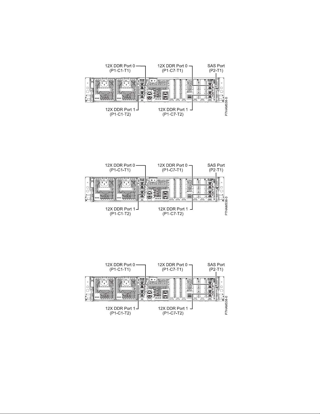
Model 8246-L1S connector locations
Learn about connector locations.
Figure 71. Model 8246-L1S connector locations
Model 8246-L1T connector locations
Learn about connector locations.
Figure 72. Model 8246-L1T connector locations
Model 8246-L2S connector locations
Learn about connector locations.
Figure 73. Model 8246-L2S connector locations
66 Power Systems: Installing the 5887 disk drive enclosure
Page 81

Model 8246-L2T connector locations
Learn about connector locations.
Figure 74. Model 8246-L2T connector locations
Model 8248-L4T, 8408-E8D, or 9109-RMD connector locations
Learn about connector locations.
The 8248-L4T, 8408-E8D, and 9109-RMD servers provide cable connector locations for the following
enclosures:
v Support for expansion units, as shown in the following figure, is as follows:
– The card installed in the C2 slot can contain two 12X double data rate (DDR) cable ports. However,
the C2 slot cannot provide both 12X DDR and PCIe cable ports.
– The card installed in the C3 slot can contain two 12X DDR cable ports. However, the C3 slot cannot
provide both 12X DDR and PCIe cable ports.
v Support for disk drive enclosures, as shown in the following figure, is as follows:
– The server contains a SAS port.
v Support for PCIe storage enclosures, as shown in the following figure, is as follows:
– The card installed in the C2 slot can contain two PCIe cable ports. However, the C2 slot cannot
provide both PCIe and 12X DDR cable ports.
– The card installed in the C3 slot can contain two PCIe cable ports. However, the C3 slot cannot
provide both PCIe and 12X DDR cable ports.
Reference information 67
Page 82

Figure 75. Model 8248-L4T, 8408-E8D, or 9109-RMD connector locations for expansion units, disk drive enclosures,
and PCIe storage enclosures
Model 9117-MMB or 9179-MHB connector locations
Learn about connector locations.
Figure 76. Model 9117-MMB or 9179-MHB connector locations
68 Power Systems: Installing the 5887 disk drive enclosure
Page 83
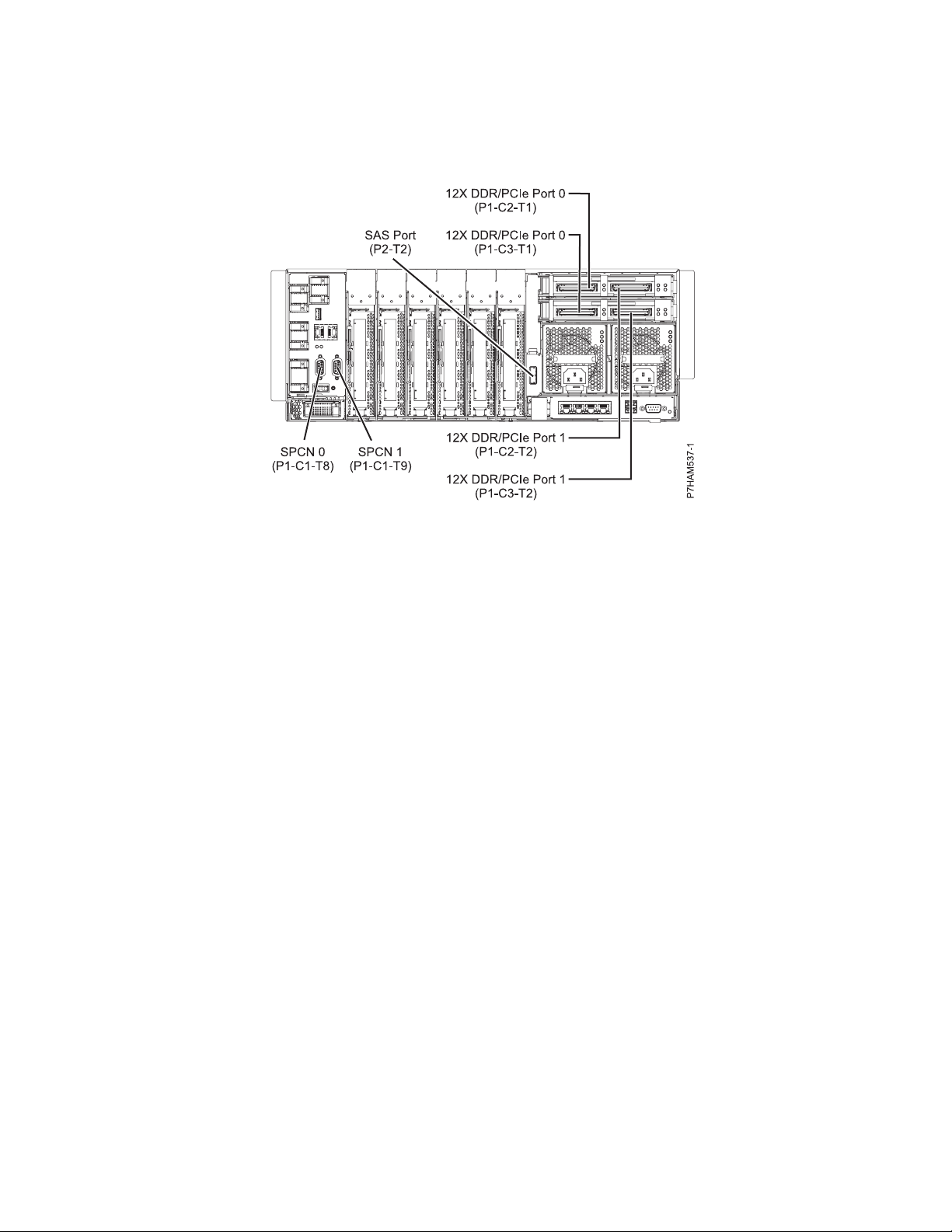
Model 9117-MMC or 9179-MHC connector locations
Learn about connector locations.
Figure 77. Model 9117-MMC or 9179-MHC connector locations
Model 9117-MMD or 9179-MHD connector locations
Learn about connector locations.
The 9117-MMD and 9179-MHD servers provide cable connector locations for the following enclosures:
v Support for expansion units, as shown in the following figure, is as follows:
– The card installed in the C2 slot can contain two 12X double data rate (DDR) cable ports. However,
the C2 slot cannot provide both 12X DDR and PCIe cable ports.
– The card installed in the C3 slot can contain two 12X DDR cable ports. However, the C3 slot cannot
provide both 12X DDR and PCIe cable ports.
v Support for disk drive enclosures, as shown in the following figure, is as follows:
– The server contains a SAS port.
v Support for PCIe storage enclosures, as shown in the following figure, is as follows:
– The card installed in the C2 slot can contain two PCIe cable ports. However, the C2 slot cannot
provide both PCIe and 12X DDR cable ports.
– The card installed in the C3 slot can contain two PCIe cable ports. However, the C3 slot cannot
provide both PCIe and 12X DDR cable ports.
Reference information 69
Page 84

Figure 78. Model 9117-MMD or 9179-MHD connector locations for expansion units, disk drive enclosures, and PCIe
storage enclosures
70 Power Systems: Installing the 5887 disk drive enclosure
Page 85

Notices
This information was developed for products and services that are offered in the USA. This material may
be available from IBM in other languages. However, you may be required to own a copy of the product
or product version in that language in order to access it.
IBM may not offer the products, services, or features discussed in this document in other countries.
Consult your local IBM representative for information on the products and services currently available in
your area. Any reference to an IBM product, program, or service is not intended to state or imply that
only that IBM product, program, or service may be used. Any functionally equivalent product, program,
or service that does not infringe any IBM intellectual property right may be used instead. However, it is
the user's responsibility to evaluate and verify the operation of any non-IBM product, program, or
service.
IBM may have patents or pending patent applications covering subject matter described in this
document. The furnishing of this document does not grant you any license to these patents. You can send
license inquiries, in writing, to:
IBM Director of Licensing
IBM Corporation
North Castle Drive, MD-NC119
Armonk, NY 10504-1785
United States of America
The following paragraph does not apply to the United Kingdom or any other country where such
provisions are inconsistent with local law: INTERNATIONAL BUSINESS MACHINES CORPORATION
PROVIDES THIS PUBLICATION "AS IS" WITHOUT WARRANTY OF ANY KIND, EITHER EXPRESS OR
IMPLIED, INCLUDING, BUT NOT LIMITED TO, THE IMPLIED WARRANTIES OF
NON-INFRINGEMENT, MERCHANTABILITY OR FITNESS FOR A PARTICULAR PURPOSE. Some
states do not allow disclaimer of express or implied warranties in certain transactions, therefore, this
statement may not apply to you.
This information could include technical inaccuracies or typographical errors. Changes are periodically
made to the information herein; these changes will be incorporated in new editions of the publication.
IBM may make improvements and/or changes in the product(s) and/or the program(s) described in this
publication at any time without notice.
Any references in this information to non-IBM websites are provided for convenience only and do not in
any manner serve as an endorsement of those websites. The materials at those websites are not part of
the materials for this IBM product and use of those websites is at your own risk.
IBM may use or distribute any of the information you supply in any way it believes appropriate without
incurring any obligation to you.
Any performance data contained herein was determined in a controlled environment. Therefore, the
results obtained in other operating environments may vary significantly. Some measurements may have
been made on development-level systems and there is no guarantee that these measurements will be the
same on generally available systems. Furthermore, some measurements may have been estimated through
extrapolation. Actual results may vary. Users of this document should verify the applicable data for their
specific environment.
Information concerning non-IBM products was obtained from the suppliers of those products, their
published announcements or other publicly available sources. IBM has not tested those products and
© Copyright IBM Corp. 2014, 2015 71
Page 86

cannot confirm the accuracy of performance, compatibility or any other claims related to non-IBM
products. Questions on the capabilities of non-IBM products should be addressed to the suppliers of
those products.
All statements regarding IBM's future direction or intent are subject to change or withdrawal without
notice, and represent goals and objectives only.
All IBM prices shown are IBM's suggested retail prices, are current and are subject to change without
notice. Dealer prices may vary.
This information is for planning purposes only. The information herein is subject to change before the
products described become available.
This information contains examples of data and reports used in daily business operations. To illustrate
them as completely as possible, the examples include the names of individuals, companies, brands, and
products. All of these names are fictitious and any similarity to the names and addresses used by an
actual business enterprise is entirely coincidental.
If you are viewing this information in softcopy, the photographs and color illustrations may not appear.
The drawings and specifications contained herein shall not be reproduced in whole or in part without the
written permission of IBM.
IBM has prepared this information for use with the specific machines indicated. IBM makes no
representations that it is suitable for any other purpose.
IBM's computer systems contain mechanisms designed to reduce the possibility of undetected data
corruption or loss. This risk, however, cannot be eliminated. Users who experience unplanned outages,
system failures, power fluctuations or outages, or component failures must verify the accuracy of
operations performed and data saved or transmitted by the system at or near the time of the outage or
failure. In addition, users must establish procedures to ensure that there is independent data verification
before relying on such data in sensitive or critical operations. Users should periodically check IBM's
support websites for updated information and fixes applicable to the system and related software.
Homologation statement
This product may not be certified in your country for connection by any means whatsoever to interfaces
of public telecommunications networks. Further certification may be required by law prior to making any
such connection. Contact an IBM representative or reseller for any questions.
Privacy policy considerations
IBM Software products, including software as a service solutions, (“Software Offerings”) may use cookies
or other technologies to collect product usage information, to help improve the end user experience, to
tailor interactions with the end user, or for other purposes. In many cases no personally identifiable
information is collected by the Software Offerings. Some of our Software Offerings can help enable you to
collect personally identifiable information. If this Software Offering uses cookies to collect personally
identifiable information, specific information about this offering’s use of cookies is set forth below.
This Software Offering does not use cookies or other technologies to collect personally identifiable
information.
If the configurations deployed for this Software Offering provide you as the customer the ability to collect
personally identifiable information from end users via cookies and other technologies, you should seek
your own legal advice about any laws applicable to such data collection, including any requirements for
notice and consent.
72 Power Systems: Installing the 5887 disk drive enclosure
Page 87

For more information about the use of various technologies, including cookies, for these purposes, see
IBM’s Privacy Policy at http://www.ibm.com/privacy and IBM’s Online Privacy Statement at
http://www.ibm.com/privacy/details the section entitled “Cookies, Web Beacons and Other
Technologies” and the “IBM Software Products and Software-as-a-Service Privacy Statement” at
http://www.ibm.com/software/info/product-privacy.
Trademarks
IBM, the IBM logo, and ibm.com are trademarks or registered trademarks of International Business
Machines Corp., registered in many jurisdictions worldwide. Other product and service names might be
trademarks of IBM or other companies. A current list of IBM trademarks is available on the web at
Copyright and trademark information at www.ibm.com/legal/copytrade.shtml.
Linux is a registered trademark of Linus Torvalds in the United States, other countries, or both.
Electronic emission notices
When attaching a monitor to the equipment, you must use the designated monitor cable and any
interference suppression devices supplied with the monitor.
Class A Notices
The following Class A statements apply to the IBM servers that contain the POWER8 processor and its
features unless designated as electromagnetic compatibility (EMC) Class B in the feature information.
Federal Communications Commission (FCC) statement
Note: This equipment has been tested and found to comply with the limits for a Class A digital device,
pursuant to Part 15 of the FCC Rules. These limits are designed to provide reasonable protection against
harmful interference when the equipment is operated in a commercial environment. This equipment
generates, uses, and can radiate radio frequency energy and, if not installed and used in accordance with
the instruction manual, may cause harmful interference to radio communications. Operation of this
equipment in a residential area is likely to cause harmful interference, in which case the user will be
required to correct the interference at his own expense.
Properly shielded and grounded cables and connectors must be used in order to meet FCC emission
limits. IBM is not responsible for any radio or television interference caused by using other than
recommended cables and connectors or by unauthorized changes or modifications to this equipment.
Unauthorized changes or modifications could void the user's authority to operate the equipment.
This device complies with Part 15 of the FCC rules. Operation is subject to the following two conditions:
(1) this device may not cause harmful interference, and (2) this device must accept any interference
received, including interference that may cause undesired operation.
Industry Canada Compliance Statement
This Class A digital apparatus complies with Canadian ICES-003.
Avis de conformité à la réglementation d'Industrie Canada
Cet appareil numérique de la classe A est conforme à la norme NMB-003 du Canada.
European Community Compliance Statement
This product is in conformity with the protection requirements of EU Council Directive 2004/108/EC on
the approximation of the laws of the Member States relating to electromagnetic compatibility. IBM cannot
Notices 73
Page 88

accept responsibility for any failure to satisfy the protection requirements resulting from a
non-recommended modification of the product, including the fitting of non-IBM option cards.
This product has been tested and found to comply with the limits for Class A Information Technology
Equipment according to European Standard EN 55022. The limits for Class A equipment were derived for
commercial and industrial environments to provide reasonable protection against interference with
licensed communication equipment.
European Community contact:
IBM Deutschland GmbH
Technical Regulations, Department M372
IBM-Allee 1, 71139 Ehningen, Germany
Tele: +49 (0) 800 225 5423 or +49 (0) 180 331 3233
email: halloibm@de.ibm.com
Warning: This is a Class A product. In a domestic environment, this product may cause radio
interference, in which case the user may be required to take adequate measures.
VCCI Statement - Japan
The following is a summary of the VCCI Japanese statement in the box above:
This is a Class A product based on the standard of the VCCI Council. If this equipment is used in a
domestic environment, radio interference may occur, in which case, the user may be required to take
corrective actions.
Japanese Electronics and Information Technology Industries Association (JEITA)
Confirmed Harmonics Guideline (products less than or equal to 20 A per phase)
Japanese Electronics and Information Technology Industries Association (JEITA)
Confirmed Harmonics Guideline with Modifications (products greater than 20 A per
phase)
74 Power Systems: Installing the 5887 disk drive enclosure
Page 89

Electromagnetic Interference (EMI) Statement - People's Republic of China
Declaration: This is a Class A product. In a domestic environment this product may cause radio
interference in which case the user may need to perform practical action.
Electromagnetic Interference (EMI) Statement - Taiwan
The following is a summary of the EMI Taiwan statement above.
Warning: This is a Class A product. In a domestic environment this product may cause radio interference
in which case the user will be required to take adequate measures.
IBM Taiwan Contact Information:
Electromagnetic Interference (EMI) Statement - Korea
Notices 75
Page 90

Germany Compliance Statement
Deutschsprachiger EU Hinweis: Hinweis für Geräte der Klasse A EU-Richtlinie zur
Elektromagnetischen Verträglichkeit
Dieses Produkt entspricht den Schutzanforderungen der EU-Richtlinie 2004/108/EG zur Angleichung der
Rechtsvorschriften über die elektromagnetische Verträglichkeit in den EU-Mitgliedsstaaten und hält die
Grenzwerte der EN 55022 Klasse A ein.
Um dieses sicherzustellen, sind die Geräte wie in den Handbüchern beschrieben zu installieren und zu
betreiben. Des Weiteren dürfen auch nur von der IBM empfohlene Kabel angeschlossen werden. IBM
übernimmt keine Verantwortung für die Einhaltung der Schutzanforderungen, wenn das Produkt ohne
Zustimmung von IBM verändert bzw. wenn Erweiterungskomponenten von Fremdherstellern ohne
Empfehlung von IBM gesteckt/eingebaut werden.
EN 55022 Klasse A Geräte müssen mit folgendem Warnhinweis versehen werden:
"Warnung: Dieses ist eine Einrichtung der Klasse A. Diese Einrichtung kann im Wohnbereich
Funk-Störungen verursachen; in diesem Fall kann vom Betreiber verlangt werden, angemessene
Maßnahmen zu ergreifen und dafür aufzukommen."
Deutschland: Einhaltung des Gesetzes über die elektromagnetische Verträglichkeit von Geräten
Dieses Produkt entspricht dem “Gesetz über die elektromagnetische Verträglichkeit von Geräten
(EMVG)“. Dies ist die Umsetzung der EU-Richtlinie 2004/108/EG in der Bundesrepublik Deutschland.
Zulassungsbescheinigung laut dem Deutschen Gesetz über die elektromagnetische Verträglichkeit von
Geräten (EMVG) (bzw. der EMC EG Richtlinie 2004/108/EG) für Geräte der Klasse A
Dieses Gerät ist berechtigt, in Übereinstimmung mit dem Deutschen EMVG das EG-Konformitätszeichen
- CE - zu führen.
Verantwortlich für die Einhaltung der EMV Vorschriften ist der Hersteller:
International Business Machines Corp.
New Orchard Road
Armonk, New York 10504
Tel: 914-499-1900
Der verantwortliche Ansprechpartner des Herstellers in der EU ist:
IBM Deutschland GmbH
Technical Regulations, Abteilung M372
IBM-Allee 1, 71139 Ehningen, Germany
Tel: +49 (0) 800 225 5423 or +49 (0) 180 331 3233
email: halloibm@de.ibm.com
Generelle Informationen:
Das Gerät erfüllt die Schutzanforderungen nach EN 55024 und EN 55022 Klasse A.
76 Power Systems: Installing the 5887 disk drive enclosure
Page 91

Electromagnetic Interference (EMI) Statement - Russia
Class B Notices
The following Class B statements apply to features designated as electromagnetic compatibility (EMC)
Class B in the feature installation information.
Federal Communications Commission (FCC) statement
This equipment has been tested and found to comply with the limits for a Class B digital device,
pursuant to Part 15 of the FCC Rules. These limits are designed to provide reasonable protection against
harmful interference in a residential installation.
This equipment generates, uses, and can radiate radio frequency energy and, if not installed and used in
accordance with the instructions, may cause harmful interference to radio communications. However,
there is no guarantee that interference will not occur in a particular installation.
If this equipment does cause harmful interference to radio or television reception, which can be
determined by turning the equipment off and on, the user is encouraged to try to correct the interference
by one or more of the following measures:
v Reorient or relocate the receiving antenna.
v Increase the separation between the equipment and receiver.
v Connect the equipment into an outlet on a circuit different from that to which the receiver is
connected.
v Consult an IBM-authorized dealer or service representative for help.
Properly shielded and grounded cables and connectors must be used in order to meet FCC emission
limits. Proper cables and connectors are available from IBM-authorized dealers. IBM is not responsible for
any radio or television interference caused by unauthorized changes or modifications to this equipment.
Unauthorized changes or modifications could void the user's authority to operate this equipment.
This device complies with Part 15 of the FCC rules. Operation is subject to the following two conditions:
(1) this device may not cause harmful interference, and (2) this device must accept any interference
received, including interference that may cause undesired operation.
Industry Canada Compliance Statement
This Class B digital apparatus complies with Canadian ICES-003.
Avis de conformité à la réglementation d'Industrie Canada
Cet appareil numérique de la classe B est conforme à la norme NMB-003 du Canada.
Notices 77
Page 92
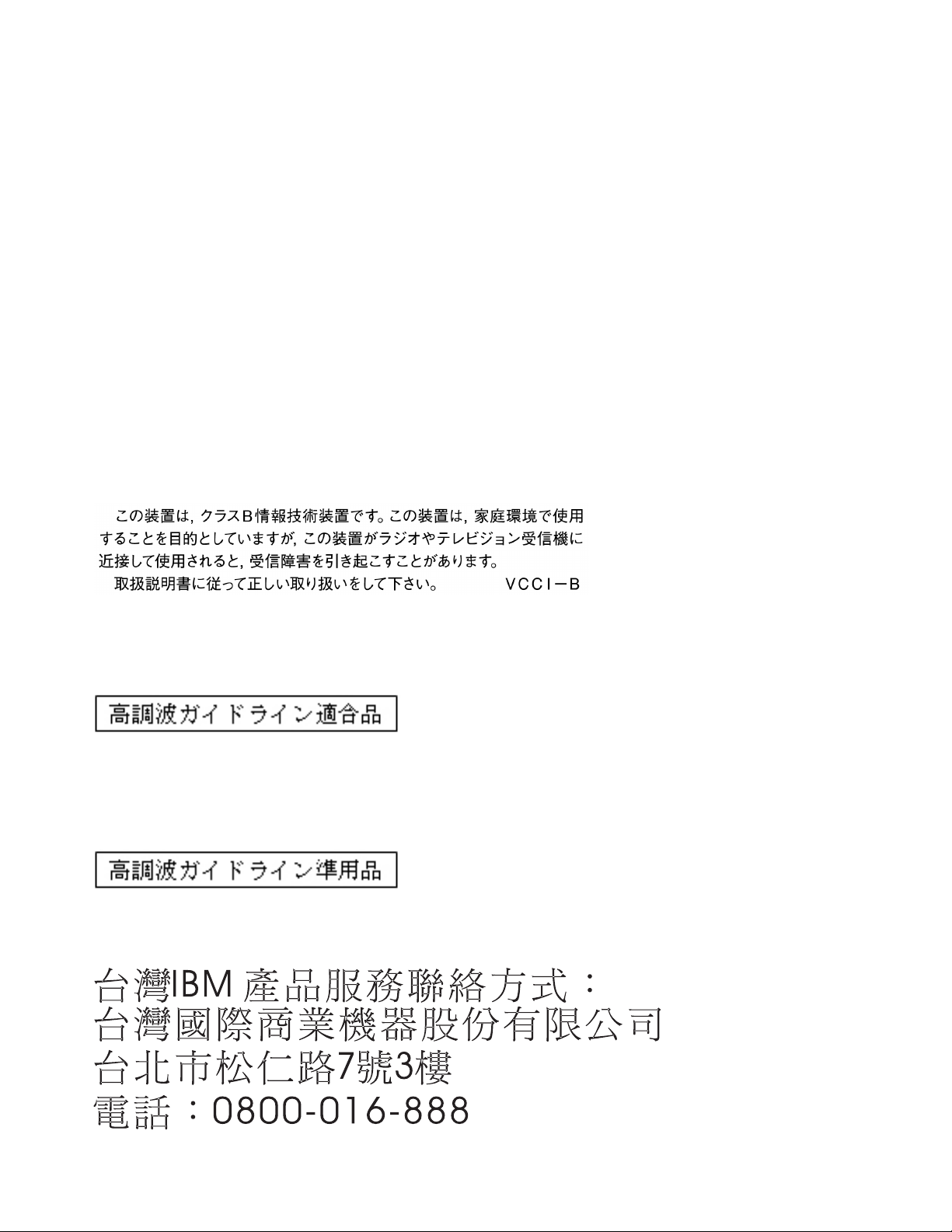
European Community Compliance Statement
This product is in conformity with the protection requirements of EU Council Directive 2004/108/EC on
the approximation of the laws of the Member States relating to electromagnetic compatibility. IBM cannot
accept responsibility for any failure to satisfy the protection requirements resulting from a
non-recommended modification of the product, including the fitting of non-IBM option cards.
This product has been tested and found to comply with the limits for Class B Information Technology
Equipment according to European Standard EN 55022. The limits for Class B equipment were derived for
typical residential environments to provide reasonable protection against interference with licensed
communication equipment.
European Community contact:
IBM Deutschland GmbH
Technical Regulations, Department M372
IBM-Allee 1, 71139 Ehningen, Germany
Tele: +49 (0) 800 225 5423 or +49 (0) 180 331 3233
email: halloibm@de.ibm.com
VCCI Statement - Japan
Japanese Electronics and Information Technology Industries Association (JEITA)
Confirmed Harmonics Guideline (products less than or equal to 20 A per phase)
Japanese Electronics and Information Technology Industries Association (JEITA)
Confirmed Harmonics Guideline with Modifications (products greater than 20 A per
phase)
IBM Taiwan Contact Information
78 Power Systems: Installing the 5887 disk drive enclosure
Page 93

Electromagnetic Interference (EMI) Statement - Korea
Germany Compliance Statement
Deutschsprachiger EU Hinweis: Hinweis für Geräte der Klasse B EU-Richtlinie zur
Elektromagnetischen Verträglichkeit
Dieses Produkt entspricht den Schutzanforderungen der EU-Richtlinie 2004/108/EG zur Angleichung der
Rechtsvorschriften über die elektromagnetische Verträglichkeit in den EU-Mitgliedsstaaten und hält die
Grenzwerte der EN 55022 Klasse B ein.
Um dieses sicherzustellen, sind die Geräte wie in den Handbüchern beschrieben zu installieren und zu
betreiben. Des Weiteren dürfen auch nur von der IBM empfohlene Kabel angeschlossen werden. IBM
übernimmt keine Verantwortung für die Einhaltung der Schutzanforderungen, wenn das Produkt ohne
Zustimmung von IBM verändert bzw. wenn Erweiterungskomponenten von Fremdherstellern ohne
Empfehlung von IBM gesteckt/eingebaut werden.
Deutschland: Einhaltung des Gesetzes über die elektromagnetische Verträglichkeit von Geräten
Dieses Produkt entspricht dem “Gesetz über die elektromagnetische Verträglichkeit von Geräten
(EMVG)“. Dies ist die Umsetzung der EU-Richtlinie 2004/108/EG in der Bundesrepublik Deutschland.
Zulassungsbescheinigung laut dem Deutschen Gesetz über die elektromagnetische Verträglichkeit von
Geräten (EMVG) (bzw. der EMC EG Richtlinie 2004/108/EG) für Geräte der Klasse B
Dieses Gerät ist berechtigt, in Übereinstimmung mit dem Deutschen EMVG das EG-Konformitätszeichen
- CE - zu führen.
Verantwortlich für die Einhaltung der EMV Vorschriften ist der Hersteller:
International Business Machines Corp.
New Orchard Road
Armonk, New York 10504
Tel: 914-499-1900
Der verantwortliche Ansprechpartner des Herstellers in der EU ist:
IBM Deutschland GmbH
Technical Regulations, Abteilung M372
IBM-Allee 1, 71139 Ehningen, Germany
Tel: +49 (0) 800 225 5423 or +49 (0) 180 331 3233
email: halloibm@de.ibm.com
Generelle Informationen:
Das Gerät erfüllt die Schutzanforderungen nach EN 55024 und EN 55022 Klasse B.
Notices 79
Page 94

Terms and conditions
Permissions for the use of these publications are granted subject to the following terms and conditions.
Applicability: These terms and conditions are in addition to any terms of use for the IBM website.
Personal Use: You may reproduce these publications for your personal, noncommercial use provided that
all proprietary notices are preserved. You may not distribute, display or make derivative works of these
publications, or any portion thereof, without the express consent of IBM.
Commercial Use: You may reproduce, distribute and display these publications solely within your
enterprise provided that all proprietary notices are preserved. You may not make derivative works of
these publications, or reproduce, distribute or display these publications or any portion thereof outside
your enterprise, without the express consent of IBM.
Rights: Except as expressly granted in this permission, no other permissions, licenses or rights are
granted, either express or implied, to the publications or any information, data, software or other
intellectual property contained therein.
IBM reserves the right to withdraw the permissions granted herein whenever, in its discretion, the use of
the publications is detrimental to its interest or, as determined by IBM, the above instructions are not
being properly followed.
You may not download, export or re-export this information except in full compliance with all applicable
laws and regulations, including all United States export laws and regulations.
IBM MAKES NO GUARANTEE ABOUT THE CONTENT OF THESE PUBLICATIONS. THE
PUBLICATIONS ARE PROVIDED "AS-IS" AND WITHOUT WARRANTY OF ANY KIND, EITHER
EXPRESSED OR IMPLIED, INCLUDING BUT NOT LIMITED TO IMPLIED WARRANTIES OF
MERCHANTABILITY, NON-INFRINGEMENT, AND FITNESS FOR A PARTICULAR PURPOSE.
80 Power Systems: Installing the 5887 disk drive enclosure
Page 95

Page 96

Part Number: 00RW813
Printed in USA
GI11-9909-02
(1P) P/N: 00RW813
 Loading...