

Page 1

IBM Tow er UPS
T1.0kVA and T1.5kVA
Installation and User's Guide
Page 2

Page 3

IBM Tow er UPS
T1.0kVA and T1.5kVA
Installation and User's Guide
Page 4

Before using this information and the product it supports, read the general information in Appendix C, “Notices,”
on page 41; and read the IBM Safety Information and the IBM Systems Environmental Notices and User Guide on the
IBM Documentation CD.
© Copyright IBM Corporation 2014.
US Government Users Restricted Rights – Use, duplication or disclosure restricted by GSA ADP Schedule Contract
with IBM Corp.
Page 5

Contents
Safety ...............v
Guidelines for trained service technicians ....vi
Inspecting for unsafe conditions ......vi
Guidelines for servicing electrical equipment . . vii
Safety statements ............viii
Product safety .............xiv
Chapter 1. Introduction ........1
Related documentation ...........1
Notices and statements ...........1
Environmental protection ..........2
Chapter 2. Presentation ........5
Standard installations ...........5
Rear panels ...............6
Control panel ..............7
LCD description .............8
Display functions ............10
User settings ..............11
Chapter 3. Installation ........17
Unpacking and contents check ........17
Battery module connection .........17
Installation of tower models .........18
Installing the communication card .......18
Chapter 4. Communication ......21
Communication ports ...........21
Characteristics of the optocouplers
communication port ..........21
Connecting the RS232 or USB communication
port ................21
Replacing the communication card ......22
Chapter 5. Operation .........23
UPS startup and shutdown .........23
Startup and Normal operation .......23
Starting the UPS on battery power......23
Shutting down the UPS .........24
Operation on battery power .........24
Return of AC input power .........24
UPS remote control functions ........24
Remote control connection and test .....25
Operating modes: summary .........25
Chapter 6. UPS maintenance .....27
Battery pack replacement ..........27
Safety considerations ..........27
Removing the battery tray on tower models . . 27
Mounting the new battery pack ......28
Chapter 7. Troubleshooting and
maintenance ............29
Alarms and faults ............29
Service and support ...........30
Chapter 8. Parts listing ........31
Appendix A. Technical specifications 33
Appendix B. Getting help and technical
assistance .............37
Before you call .............37
Using the documentation ..........38
Getting help and information from the World Wide
Web.................38
How to send DSA data to IBM ........38
Software service and support ........38
Hardware service and support ........38
IBM Taiwan product service .........39
Appendix C. Notices .........41
Trademarks ..............41
Important notes .............42
Particulate contamination..........42
Telecommunication regulatory statement ....43
Electronic emission notices .........43
Federal Communications Commission (FCC)
statement ..............44
Industry Canada Class A emission compliance
statement ..............44
Avis de conformité à la réglementation
d'Industrie Canada ...........44
Australia and New Zealand Class A statement . 44
European Union EMC Directive conformance
statement ..............44
Germany Class A statement ........45
Japan VCCI Class A statement .......46
Japan Electronics and Information Technology
Industries Association (JEITA) statement....46
Korea Communications Commission (KCC)
statement ..............46
Russia Electromagnetic Interference (EMI) Class
A statement .............46
People's Republic of China Class A electronic
emission statement ...........46
Taiwan Class A compliance statement ....47
Appendix D. Glossary ........49
© Copyright IBM Corp. 2014 iii
Page 6

iv Installation and User's Guide
Page 7
Safety
Before installing this product, read the Safety Information.
Antes de instalar este produto, leia as Informações de Segurança.
Læs sikkerhedsforskrifterne, før du installerer dette produkt.
Lees voordat u dit product installeert eerst de veiligheidsvoorschriften.
Ennen kuin asennat tämän tuotteen, lue turvaohjeet kohdasta Safety Information.
Avant d'installer ce produit, lisez les consignes de sécurité.
Vor der Installation dieses Produkts die Sicherheitshinweise lesen.
Prima di installare questo prodotto, leggere le Informazioni sulla Sicurezza.
© Copyright IBM Corp. 2014 v
Page 8

Les sikkerhetsinformasjonen (Safety Information) før du installerer dette produktet.
Antes de instalar este produto, leia as Informações sobre Segurança.
Antes de instalar este producto, lea la información de seguridad.
Läs säkerhetsinformationen innan du installerar den här produkten.
Guidelines for trained service technicians
This section contains information for trained service technicians.
Inspecting for unsafe conditions
Use this information to help you identify potential unsafe conditions in an IBM
product that you are working on.
Each IBM product, as it was designed and manufactured, has required safety items
to protect users and service technicians from injury. The information in this section
addresses only those items. Use good judgment to identify potential unsafe
conditions that might be caused by alterations or attachment of non-IBM features
or optional devices that are not addressed in this section. If you identify an unsafe
condition, you must determine how serious the hazard is and whether you must
correct the problem before you work on the product.
vi Installation and User's Guide
®
Page 9

Consider the following conditions and the safety hazards that they present:
v Electrical hazards, especially primary power. Primary voltage on the frame can
cause serious or fatal electrical shock.
v Explosive hazards, such as a damaged CRT face or a bulging capacitor.
v Mechanical hazards, such as loose or missing hardware.
To inspect the product for potential unsafe conditions, complete the following
steps:
1. Make sure that the power is off and the power cords are disconnected.
2. Make sure that the exterior cover is not damaged, loose, or broken, and observe
any sharp edges.
3. Check the power cords:
v Make sure that the third-wire ground connector is in good condition. Use a
meter to measure third-wire ground continuity for 0.1 ohm or less between
the external ground pin and the frame ground.
v Make sure that the power cords are the correct type.
v Make sure that the insulation is not frayed or worn.
4. Remove the cover.
5. Check for any obvious non-IBM alterations. Use good judgment as to the safety
of any non-IBM alterations.
6. Check inside the system for any obvious unsafe conditions, such as metal
filings, contamination, water or other liquid, or signs of fire or smoke damage.
7. Check for worn, frayed, or pinched cables.
8. Make sure that the power-supply cover fasteners (screws or rivets) have not
been removed or tampered with.
Guidelines for servicing electrical equipment
Observe these guidelines when you service electrical equipment.
v Check the area for electrical hazards such as moist floors, nongrounded power
extension cords, and missing safety grounds.
v Use only approved tools and test equipment. Some hand tools have handles that
are covered with a soft material that does not provide insulation from live
electrical current.
v Regularly inspect and maintain your electrical hand tools for safe operational
condition. Do not use worn or broken tools or testers.
v Do not touch the reflective surface of a dental mirror to a live electrical circuit.
The surface is conductive and can cause personal injury or equipment damage if
it touches a live electrical circuit.
v Some rubber floor mats contain small conductive fibers to decrease electrostatic
discharge. Do not use this type of mat to protect yourself from electrical shock.
v Do not work alone under hazardous conditions or near equipment that has
hazardous voltages.
v Locate the emergency power-off (EPO) switch, disconnecting switch, or electrical
outlet so that you can turn off the power quickly in the event of an electrical
accident.
v Disconnect all power before you perform a mechanical inspection, work near
power supplies, or remove or install main units.
v Before you work on the equipment, disconnect the power cord. If you cannot
disconnect the power cord, have the customer power-off the wall box that
supplies power to the equipment and lock the wall box in the off position.
Safety vii
Page 10

v Never assume that power has been disconnected from a circuit. Check it to
v If you have to work on equipment that has exposed electrical circuits, observe
v Use extreme care when you measure high voltages.
v To ensure proper grounding of components such as power supplies, pumps,
v If an electrical accident occurs, use caution, turn off the power, and send another
Safety statements
These statements provide the caution and danger information that is used in this
documentation.
make sure that it has been disconnected.
the following precautions:
– Make sure that another person who is familiar with the power-off controls is
near you and is available to turn off the power if necessary.
– When you work with powered-on electrical equipment, use only one hand.
Keep the other hand in your pocket or behind your back to avoid creating a
complete circuit that could cause an electrical shock.
– When you use a tester, set the controls correctly and use the approved probe
leads and accessories for that tester.
– Stand on a suitable rubber mat to insulate you from grounds such as metal
floor strips and equipment frames.
blowers, fans, and motor generators, do not service these components outside of
their normal operating locations.
person to get medical aid.
Important:
Each caution and danger statement in this documentation is labeled with a
number. This number is used to cross reference an English-language caution or
danger statement with translated versions of the caution or danger statement in
the Safety Information document.
For example, if a danger statement is labeled D005, translations for that caution
statement are in the Safety Information document under D005.
Be sure to read all caution and danger statements in this documentation before you
perform the procedures. Read any additional safety information that comes with
your system or optional device before you install the device.
viii Installation and User's Guide
Page 11

L001
DANGER
Hazardous voltage, current, or energy levels are present inside any component
that has this label attached. Do not open any cover or barrier that contains
this label.
(L001)
Safety ix
Page 12

D005
DANGER
When working on or around the system, observe the following precautions:
Electrical voltage and current from power, telephone, and communication
cables are hazardous. To avoid a shock hazard:
v If IBM supplied a power cord(s), connect power to this unit only with the
IBM provided power cord. Do not use the IBM provided power cord for
any other product.
v Do not open or service any power supply assembly.
v Do not connect or disconnect any cables or perform installation,
maintenance, or reconfiguration of this product during an electrical storm.
v The product might be equipped with multiple power cords. To remove all
hazardous voltages, disconnect all power cords.
v Connect all power cords to a properly wired and grounded electrical outlet.
Ensure that the outlet supplies proper voltage and phase rotation according
to the system rating plate.
v Connect any equipment that will be attached to this product to properly
wired outlets.
v When possible, use one hand only to connect or disconnect signal cables.
v Never turn on any equipment when there is evidence of fire, water, or
structural damage.
v Disconnect the attached power cords, telecommunications systems,
networks, and modems before you open the device covers, unless
instructed otherwise in the installation and configuration procedures.
v Connect and disconnect cables as described in the following procedures
when installing, moving, or opening covers on this product or attached
devices.
To disconnect:
1. Turn off everything (unless instructed otherwise).
2. Remove the power cords from the outlets.
3. Remove the signal cables from the connectors.
4. Remove all cables from the devices.
To connect:
1. Turn off everything (unless instructed otherwise).
2. Attach all cables to the devices.
3. Attach the signal cables to the connectors.
4. Attach the power cords to the outlets.
5. Turn on the devices.
v Sharp edges, corners and joints might be present in and around the system.
Use care when handling equipment to avoid cuts, scrapes and pinching.
(D005)
x Installation and User's Guide
Page 13

C004
CAUTION:
Lead-acid batteries can present a risk of electrical burn from high, short-circuit
current. Avoid battery contact with metal materials; remove watches, rings, or
other metal objects, and use tools with insulated handles. To avoid possible
explosion, do not burn.
Exchange only with the IBM-approved part. Recycle or discard the battery as
instructed by local regulations. In the United States, IBM has a process for the
collection of this battery. For information, call 1-800-426-4333. Have the IBM part
number for the battery unit available when you call. (C004)
C009
CAUTION:
>18 kg (39.7 lb)
or
18-32 kg (39.7-70.5 lb)
or
The weight of this part or unit is between 18 and 32 kg (39.7 and 70.5 lb). It
takes two persons to safely lift this part or unit. (C009)
C010
CAUTION:
>32 kg (70.5 lb)
or
The weight of this part or unit is between 32 and 55 kg (70.5 and 121.2 lb). It
takes three persons to safely lift this part or unit. (C010)
32-55 kg (70.5-121.2 lb)
or
Safety xi
Page 14

C022
CAUTION:
This product might be equipped with a hard-wired power cable. Ensure that a
licensed electrician performs the installation per the national electrical code.
(C022)
xii Installation and User's Guide
Page 15
R001
Important: The following general safety information should be used for all
rack-mounted devices:
DANGER
Observe the following precautions when working on or around your IT rack
system:
v Heavy equipment—personal injury or equipment damage might result if
mishandled.
v Always lower the leveling pads on the rack cabinet.
v Always install stabilizer brackets on the rack cabinet.
v To avoid hazardous conditions due to uneven mechanical loading, always
install the heaviest devices in the bottom of the rack cabinet. Always install
servers and optional devices starting from the bottom of the rack cabinet.
v Rack-mounted devices are not to be used as shelves or work spaces. Do not
place objects on top of rack-mounted devices.
v Each rack cabinet might have more than one power cord. Be sure to
disconnect all power cords in the rack cabinet when directed to disconnect
power during servicing.
v Connect all devices installed in a rack cabinet to power devices installed in
the same rack cabinet. Do not plug a power cord from a device installed in
one rack cabinet into a power device installed in a different rack cabinet.
v An electrical outlet that is not correctly wired could place hazardous
voltage on the metal parts of the system or the devices that attach to the
system. It is the responsibility of the customer to ensure that the outlet is
correctly wired and grounded to prevent an electrical shock.
(R001 part 1 of 2)
Safety xiii
Page 16

CAUTION:
v Do not install a unit in a rack where the internal rack ambient temperatures
will exceed the manufacturer’s recommended ambient temperature for all your
rack-mounted devices.
v Do not install a unit in a rack where the air flow is compromised. Ensure that
air flow is not blocked or reduced on any side, front, or back of a unit used
for air flow through the unit.
v Consideration should be given to the connection of the equipment to the
supply circuit so that overloading of the circuits does not compromise the
supply wiring or overcurrent protection. To provide the correct power
connection to a rack, refer to the rating labels located on the equipment in the
rack to determine the total power requirement of the supply circuit.
v (For sliding drawers) Do not pull out or install any drawer or feature if the rack
stabilizer brackets are not attached to the rack. Do not pull out more than one
drawer at a time. The rack might become unstable if you pull out more than
one drawer at a time.
v (For fixed drawers) This drawer is a fixed drawer and must not be moved for
servicing unless specified by the manufacturer. Attempting to move the
drawer partially or completely out of the rack might cause the rack to become
unstable or cause the drawer to fall out of the rack.
(R001 part 2 of 2)
Product safety
Output power and ampere ratings
Important: Make sure that the power receptacle is near the equipment and is
easily accessible so that the uninterruptible power supply (UPS) can be
disconnected quickly.
To reduce the risk of fire, connect only to a circuit provided with branch circuit
overcurrent protection with an ampere rating in accordance with the National
Electrical Code (NEC), ANSI/NFPA 70 or your local electrical code:
UPS output power 120 V 208 V 230 V
1500 VA 15 A Not applicable 10 A
2200 VA 20 A Not applicable 10 A
3000 VA 30 A 20 A 16 A
v The UPS connection instructions and operations described in the manual must
be followed in the indicated order.
v
Important: To reduce the risk of fire, the unit connects only to a circuit provided
with branch circuit overcurrent protection as described in this manual, in
accordance with the National Electric Code, ANSI/NFPA 70.
xiv Installation and User's Guide
Page 17

The upstream circuit breaker for Normal AC and Bypass AC must be easily
accessible. The unit can be disconnected from AC power source by opening this
circuit breaker. This circuit breaker is used for backfeed protection and must
comply with IEC/EN 62040-1 (the creepage and clearance distances shall meet
the basic insulation requirements for pollution degree 2).
v Disconnection and overcurrent protection devices shall be provided by others for
permanently connected AC input (Normal AC and Bypass AC) and AC output
circuits.
v Check that the indications on the rating plate correspond to your AC powered
system and to the actual electrical consumption of all the equipment to be
connected to the system.
v For PLUGGABLE EQUIPMENT, the socket-outlet shall be installed near the
equipment and shall be easily accessible.
v Never install the system near liquids or in an excessively damp environment.
v Never let a foreign body penetrate inside the system.
v Never block the ventilation grates of the system.
v Never expose the system to direct sunlight or source of heat.
v If the system must be stored prior to installation, storage must be in a dry place.
v The admissible storage temperature range is -15ºC to +50ºC.
v This unit is not designed to conform to ANSI/NFPA 75 and therefore is not for
use in ANSI/NFPA 75-certified data centers.
v Although the UPS does not contain anti-backfeed (ABF) relays, some backfeed
protection is provided. For example, if some components are damaged in battery
mode, the output voltage may feed back to the input. In this case, a current
transformer (CT) is used to detect the bypass current feedback voltage. If a
current backfeed fault condition is detected, the UPS will terminate the inverter
output to avoid personal injury.
Safety xv
Page 18

xvi Installation and User's Guide
Page 19

Chapter 1. Introduction
Thank you for selecting an IBM product to protect your electrical equipment.
Read this manual to take full advantage of the features of your equipment.
Before installing your equipment, read the safety instructions. Then, follow the
instructions in this manual for setting up and using the product.
To discover the entire range of IBM products and the options available for the IBM
UPS device, we invite you to visit our web site at www.ibm.com or contact your
IBM representative.
Related documentation
In addition to this document, the following documentation is available:
v Environmental Notices and User Guide
This document is provided on the IBM Documentation CD, and it contains
translated environmental notices.
v Safety Information
This document is provided on the IBM Documentation CD, and it contains
translated caution and danger statements. Each caution and danger statement
that appears in the documentation has a number that you can use to locate the
corresponding statement in your language in the Safety Information document.
v License Agreement for Machine Code
This document is provided on the IBM Documentation CD, and it contains the
translated license agreement for the product.
v Warranty Information
This multilingual document comes with the device, and it contains information
about the terms of the warranty.
Notices and statements
The caution and danger statements in this document are also in the multilingual
Safety Information document, which is on the IBM Documentation CD. Each
statement is numbered for reference to the corresponding statement in the Safety
Information document.
Notices and statements in this document
The following notices and statements are used in this document:
v Note: These notices provide important tips, guidance, or advice.
v Important: These notices provide information or advice that might help you
avoid inconvenient or problem situations.
v Attention: These notices indicate possible damage to programs, devices, or data.
An attention notice is placed just before the instruction or situation in which
damage might occur.
v Caution: These statements indicate situations that can be potentially hazardous
to you. A caution statement is placed just before the description of a potentially
hazardous procedure step or situation.
© Copyright IBM Corp. 2014 1
Page 20

v Danger: These statements indicate situations that can be potentially lethal or
hazardous to you. A danger statement is placed just before the description of a
potentially lethal or hazardous procedure step or situation.
Environmental protection
IBM has implemented an environmental-protection policy. Products are developed
according to an eco-design approach.
Substances
This product does not contain CFCs, HCFCs or asbestos.
Packing
To improve waste treatment and facilitate recycling, separate the various packing
components.
v The cardboard we use comprises over 50% of recycled cardboard.
v Sacks and bags are made of polyethylene.
v Packing materials are recyclable and bear the appropriate identification symbol
01
.
PET
Materials Abbreviations Number in the symbols
Polyethylene terephthalat PET 01
High-density polyethylene HDPE 02
Polyvinyl chloride PVC 03
Low-density polyethylene LDPE 04
Polypropylene PP 05
Polystyrene PS 06
01
PET
Follow all local regulations for the disposal of packing materials.
Refer to the IBM Environmental Notices and User's Guide, provided on the
documentation CD.
End of life
IBM will process products at the end of their service life in compliance with local
regulations. IBM works with companies in charge of collecting and eliminating our
products at the end of their service life.
Product
The product is made up of recyclable materials. Dismantling and destruction must
take place in compliance with all local regulations concerning waste. At the end of
its service life, the product must be transported to a processing center for electrical
and electronic waste.
Battery
The product contains lead-acid batteries that must be processed according to
applicable local regulations concerning batteries.
2 Installation and User's Guide
Page 21

The battery pack can be removed to comply with regulations and in view of
correct disposal.
With the IBM UPS device, you can eliminate the effects of power disturbances and
guard the integrity of your equipment. Providing outstanding performance and
reliability, the IBM UPS device's unique benefits include:
v True online double-conversion technology with high power density, utility
frequency independence, and power generator compatibility.
v Advanced Battery Management ( ABM ) technology that uses advanced battery
management to increase battery service life, optimize recharge time, and provide
a warning before the end of useful battery life.
v Selectable High Efficiency mode of operation.
v Standard communication options: one RS-232 communication port, one USB
communication port, and relay output contacts.
v UPS Network Management Card with enhanced communication capabilities.
v Extended runtime with up to four Extended Battery Modules (EBMs) per UPS.
v Firmware that is easily upgradable without a service call.
v Remote On/Off control through Remote On/Off (ROO) and Remote Power Off
(RPO) ports.
Chapter 1. Introduction 3
Page 22

4 Installation and User's Guide
Page 23

Chapter 2. Presentation
Standard installations
Tower models
D
H
W
Weights
Machine types and models
5595-1AX 24.4 / 11.5 13.6 x 5.9 x 9.1 / 345 x 150 x
5595-2AX 35.3 / 16.2 17.5 x 5.9 x 9.1 / 445 x 150 x
5595-1KX 24.4 / 11.5 13.6 x 5.9 x 9.1 / 345 x 150 x
5595-2KX 35.2 / 16.2 17.5 x 5.9 x 9.1 / 445 x 150 x
(lb/kg)
Dimensions (inch/mm)
DxWxH
233
233
233
233
© Copyright IBM Corp. 2014 5
Page 24
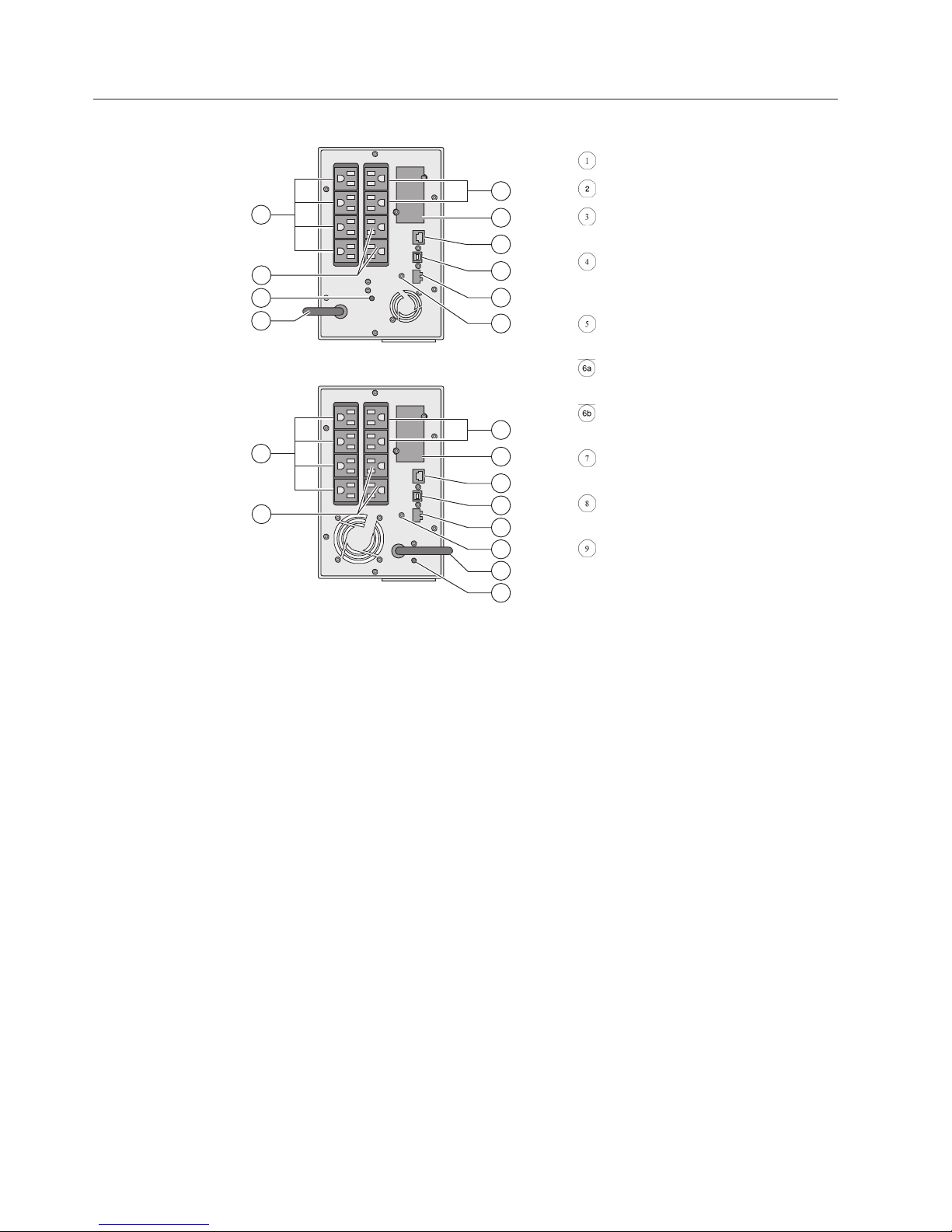
Rear panels
USB communication port
5
6b
8
7
Figure 1. 5595-1AX
5
6b
Figure 2. 5595-2AX
6a
6a
RS232 communication port
3
2
1
4
9
Slot where UPS Network
Management Card is installed
Connector for Remote On/Off
(ROO) control or Remote Power Off
(RPO) control
Outlets for connection of critical
equipment (Primary outlet group)
Outlet Group 1: programmable
outlets for connection of equipment
Outlet Group 2: programmable
outlets for connection of equipment
3
2
1
4
9
7
8
Attached 6 ft. (1.8m) input power
cord for AC-power source (5-15P)
LED indicating site wiring fault
(SWF) alarm
Ground screw
6 Installation and User's Guide
Page 25

6b
USB communication port
5
7
6a
3
2
1
4
8
RS232 communication port
Slot where UPS Network
Management Card is installed
Connector for Remote On/Off
(ROO) control or Remote Power Off
(RPO) control
Outlets for connection of critical
equipment (Primary outlet group)
Control panel
Figure 3. 5595-1KX
Outlet Group 1: programmable
outlets for connection of equipment
Outlet Group 2: programmable
outlets for connection of equipment
Socket for connection to AC-power
source
Ground screw
6b
6a
5
3
2
1
4
8
7
Figure 4. 5595-2KX
The UPS has a five-button graphical LCD. It provides useful information about the
UPS itself, load status, events, measurements and settings.
Chapter 2. Presentation 7
Page 26

Power On
Indicator
(green)
On Battery
Indicator
(yellow)
Normal mode
Alarm
Indicator
(red)
100 %
720W
800VA
Efficiency: ~98%
100 %
10mi n
Escape Up Down Enter On/Off
button
The following table shows the indicator status and description:
Indicator Status Description
Green
Yellow
Red
On The UPS is operating
normally.
On The UPS is on Battery mode.
On The UPS has an active alarm
or fault. See Chapter 7,
“Troubleshooting and
maintenance,” on page 29 for
additional information.
LCD description
After 5 minutes of inactivity, the LCD displays the screen saver.
The LCD backlight automatically dims after 10 minutes of inactivity. Press any
button to restore the screen.
8 Installation and User's Guide
Page 27
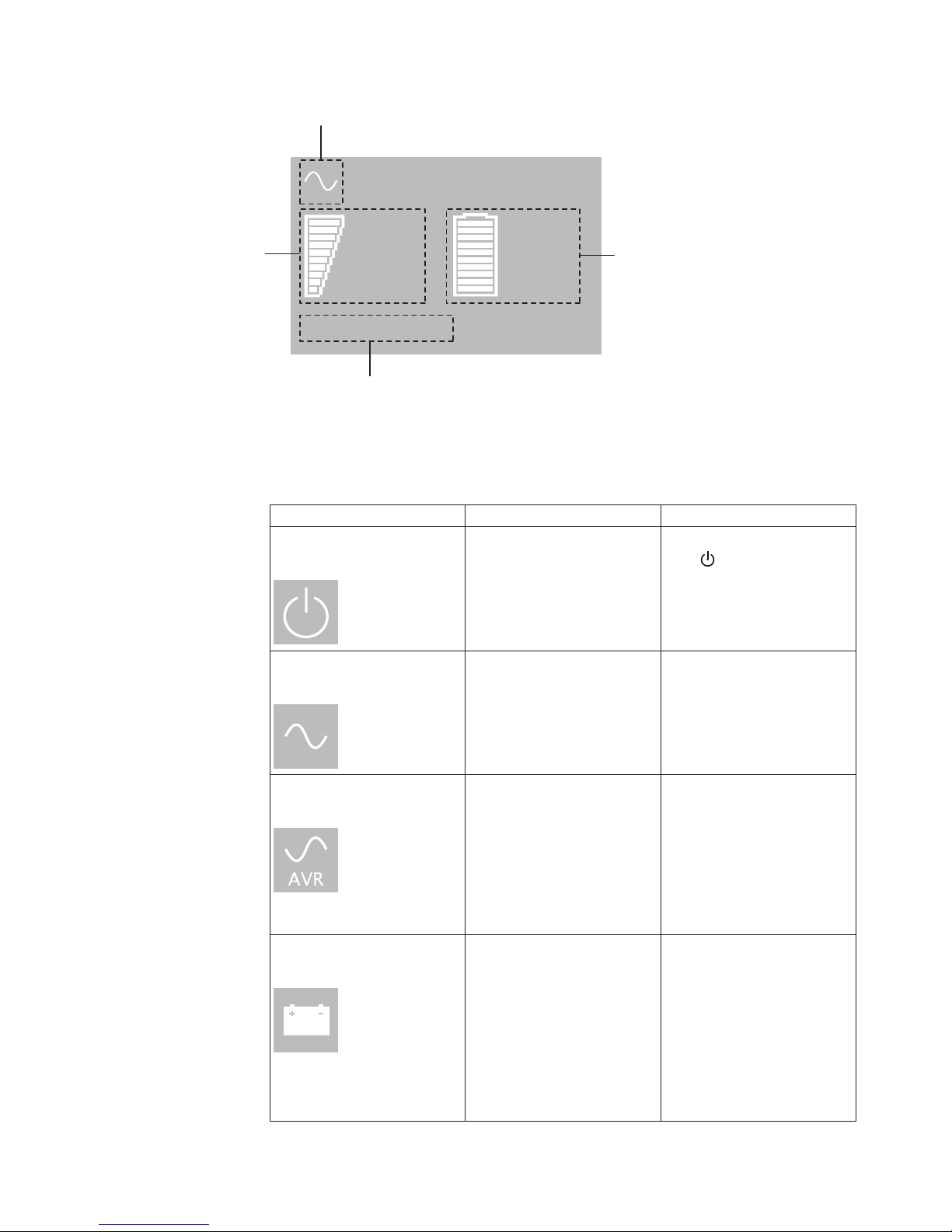
Operation status
Normal mode
Load/equipment status
100%
720W
100%
10min
Battery status
800VA
Efficiency: ~98%
Efficiency and load group information
The following table describes the status information provided by the UPS.
Note: If an other indicator appears, see Chapter 7, “Troubleshooting and
maintenance,” on page 29 for additional information.
Operation status Cause Description
Standby mode
Normal mode
The UPS is OFF, waiting for
start-up command from the
user.
The UPS is operating
normally.
Equipment is not powered
until
The UPS is powering and
protecting the equipment.
button is pressed.
In AVR mode
No beep
On Battery
Battery LED is on
1 beep every 10 seconds
The UPS is operating
normally but the utility
voltage is outside normal
mode thresholds.
A utility failure has occurred
and the UPS is in Battery
mode.
The UPS is powering the
equipment through an
Automatic Voltage
Regulation device.
The equipment is still
normally protected.
The UPS is powering the
equipment with the battery
power. Prepare your
equipment for shutdown.
Chapter 2. Presentation 9
Page 28

Operation status Cause Description
End of backup time
1 beep every 3 seconds
Display functions
Press the Enter ( ) button to activate the menu options. Use the two middle
buttons (
button to select an option. Press the button to cancel or return to the previous
menu.
Main menu Submenu Display information or Menu function
Measurements Load W VA / Load A pf / Output V Hz
Control Load Segments
The UPS is on Battery mode
and the battery packs are
running low.
This warning is approximate,
and the actual time to shut
down might vary
significantly.
Depending on the UPS load,
the "Battery Low" warning
might occur before the
battery packs reach 20 %
capacity.
and ) to scroll through the menu structure. Press the Enter ( )
/ Input V Hz / Battery V min /
Efficiency / Power usage
Outlet Group 1: ON / OFF
Outlet Group 2: ON / OFF
These commands overrule user settings
for load segments.
Start battery test Starts a manual battery test
Reset fault state Clears active fault (UPS restart required)
Restore factory settings Returns all settings to original values
Reset power usage Clears power usage measurements
Settings Local settings Sets product general parameters
Input/output settings Sets input and output parameters
On/Off settings Sets On/Off conditions
Battery settings Sets battery configuration
Fault log Displays event log or alarms
Identification UPS Type / Part Number / Serial
Number / Firmware release / Com. card
address
10 Installation and User's Guide
Page 29

User settings
The following table displays the options that can be changed by the user.
Submenu Available settings Default settings
Local settings Language
[language_name]
[English]
Select the desired
language from the
list. Menus, status,
notices and alarms,
UPS fault, Event Log
data and settings are
in all supported
languages.
LCD settings Modify LCD screen
brightness and
contrast to be
adapted to room
light conditions.
Audible alarm
[Enabled] [Disabled
on battery] [Always
disabled]
Enable or disable the
buzzer if an alarm
occurs.
User selectable when
UPS is powered for
the first time.
[Enabled]
Chapter 2. Presentation 11
Page 30

Submenu Available settings Default settings
In/Out settings Output voltage
Input thresholds
Sensitivity
[100 V][120 V][125
V][200 V][208 V][220
V][230 V][240 V]
[Normal mode]
[Extended mode]
Extended mode
reduces lower input
voltage to 70 V
before UPS transfers
to battery power.
This can be used if
the load can
withstand low
voltage supply.
[High] [Low]
High: for sensitive
equipment, UPS will
easily transfer to
battery power when
utility conditions are
becoming bad.
User selectable when
UPS is powered for
the first time.
[Normal mode]
[High]
Low: for equipment
that can withstand
bad utility
conditions, in that
case, the UPS will
not transfer to
battery power.
12 Installation and User's Guide
Page 31

In/Out settings
(continued)
Submenu Available settings Default settings
Load segments Auto start delay
[No Delay] [1 s] [2
s]...[65354 s]
Outlet Group 1: [3 s]
The connected load is
powered after the
specified delay.
Load segments Auto shutdown delay
[Disabled] [0s] [1 s]
[2 s]...[65354 s]
During a power
outage, authorizes
UPS to turn off
power to equipment
connected to Outlet
Group 1 and/or
Outlet Group 2
outlets.
This feature allows
the shedding of
non-critical loads in
order to conserve
battery power for
critical loads
connected to the
Primary outlet group.
Overload prealarm [10 %] [15 %] [20 %]
... [100 %] [105 %]
Outlet Group 2: [6 s]
Outlet Group 1:
[Disabled]
Outlet Group 2:
[Disabled]
[105%]
Sets critical
percentage of load
where alarm
overload alarm
occurs.
Chapter 2. Presentation 13
Page 32

Submenu Available settings Default settings
ON/OFF settings Cold start [Enabled] [Disabled]
Enables the product
to be started on
battery power.
First cold start is
always disabled.
Forced reboot [Enabled] [Disabled]
If mains recover
during a shutdown
sequence:
If Enabled, shutdown
sequence will
complete and wait 10
seconds prior to
restart, if set to
Disable, shutdown
sequence will not
complete and restart
will occur
immediately.
Auto restart [Enabled] [Disabled]
[Enabled]
[Enabled]
[Enabled]
Enables the product
to restart
automatically when
mains recovers after
a complete battery
discharge.
14 Installation and User's Guide
Page 33

ON/OFF settings
(continued)
Submenu Available settings Default settings
Energy saving [Enabled] [Disabled]
[Disabled]
If Enabled, UPS will
shut down after 5
min. of back-up time,
if no load is detected
on the output.
Sleep mode [Enabled] [Disabled]
[Disabled]
If Disabled, LCD and
communication will
turn OFF
immediately after
UPS is OFF.
If Enabled, LCD and
communication stays
ON 1h30 min. after
UPS is OFF.
Remote command [Enabled] [Disabled]
[Enabled]
If Enabled, shutdown
or restart commands
from software are
authorized.
RPO delay [0 s] [1s ] [2 s]...[180
[0 s]
s]
Delays remote power
off command
Chapter 2. Presentation 15
Page 34

Submenu Available settings Default settings
Battery settings Automatic battery
test
Low battery warning [1 %] [2 %] ... [100 %]
Restart battery level [1 %] [2 %] ... [100 %]
Battery charge mode [ABM cycling]
Deep discharge
protection
[No test] [Every day]
[Every week] [Every
month]
Available only if
battery charge mode
is set to constant
charge.
The alarm triggers
when the set
percentage of battery
capacity is reached
during a back-up
time.
If set, automatic
restart will occur
only when
percentage of battery
charge is reached.
[Constant charge]
[Yes] [No]
If set to Yes, the UPS
automatically
prevents the battery
packs from deep
discharge by
adapting end of
back-up time voltage
threshold.
Every week (in
constant charge)
otherwise following
ABM
[20%]
[0%]
[ABM cycling]
[Yes]
16 Installation and User's Guide
Page 35
Chapter 3. Installation
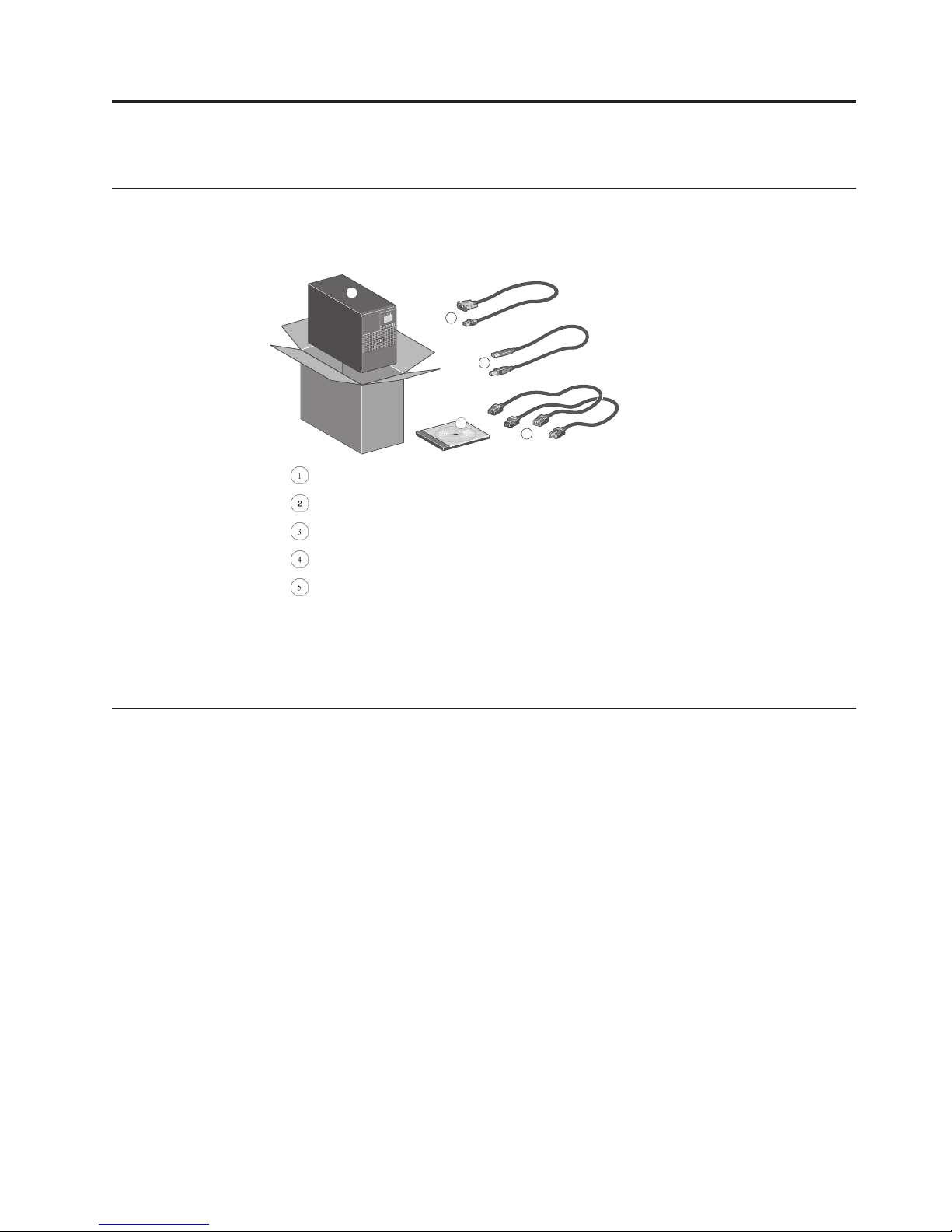
Unpacking and contents check
About this task
1
2
3
IBM UPS
RS232 communication cable
USB communication cable
2 connection cables for the protected equipments (5595-1AX and 5595-2AX models)
Documentation and software kit
Note: Packing materials must be disposed of in compliance with all local
regulations concerning waste. Recycling symbols are printed on the packing
materials to facilitate sorting.
Battery module connection
About this task
Important: Before starting the UPS, connect the internal battery pack.
Note: A small amount of arcing might occur when connecting the battery pack.
This is normal and does not damage the UPS or present any safety concern.
5
4
© Copyright IBM Corp. 2014 17
Page 36

Installation of tower models
Remove the front panel.
Connect the battery
module (never pull on the
wires).
Attach the front panel.
Figure 5. Setup for tower installation
Installing the communication card
About this task
Note: It is not necessary to shut down the UPS before installing the UPS Network
Management Card.
18 Installation and User's Guide
Page 37

1. Remove the connector panel blank ( ),
which is secured by two screws.
2. Insert the UPS Network Management
Card into the slot.
1
3. Secure the panel by tightening the two
screws.
Chapter 3. Installation 19
Page 38

20 Installation and User's Guide
Page 39
Chapter 4. Communication
Communication ports
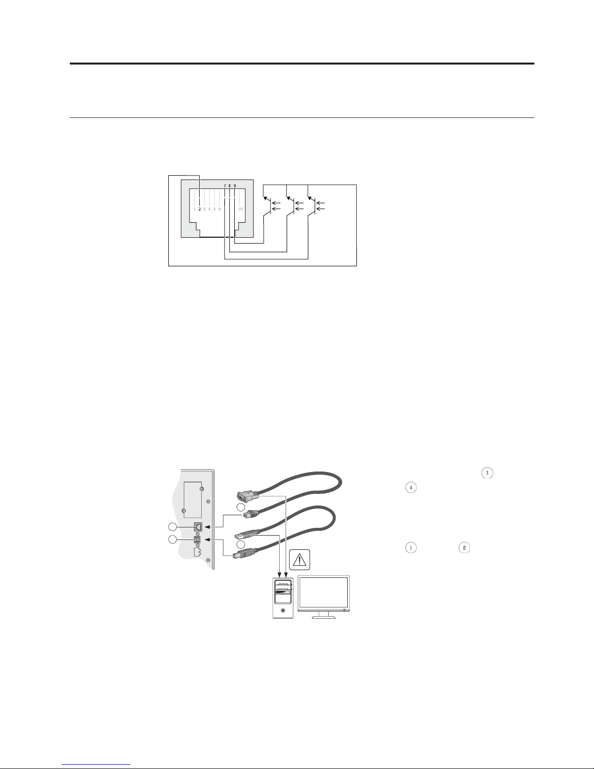
Characteristics of the optocouplers communication port
When a signal is activated, the contact is closed between the common (pin 2) and
the pin for the corresponding signal.
Contact characteristics (optocoupler):
v Voltage: 48 V DC max
v Current: 25 mA max
v Power: 1.2 W
Pins 1, 3, 4, 5, 6, 10: not used
Pin 2: common
Pin 7: low battery
Pin 8: operation on battery power
Pin 9: UPS ON, equipment supplied
n.o.: normally open contact
Connecting the RS232 or USB communication port
About this task
Note: The RS232 and USB communication ports cannot operate simultaneously.
1. Connect the RS232 or USB
communication cable to the
3
2
1
4
serial or USB port on the
computer equipment.
2. Connect the other end of the
communication cable to the USB
or RS232
communication port on the
UPS.
The UPS can now communicate
with IBM power management
software.
© Copyright IBM Corp. 2014 21
Page 40

Replacing the communication card
About this task
Follow these steps to replace the UPS Network Management Card.
1. Turn off the UPS.
2. Disconnect the network cable.
3. Remove the connector panel blank (
which is secured by two screws.
1
4. Insert the UPS Network Management
Card into the slot.
5. Secure the panel by tightening the two
screws.
),
22 Installation and User's Guide
Page 41

Chapter 5. Operation
UPS startup and shutdown
Startup and Normal operation
About this task
To start the UPS:
Procedure
1. Verify that the UPS power cord is plugged in.
2. The UPS front panel display illuminates and shows the IBM logo.
3. Verify that the UPS status screen shows
4. Press the
The UPS front panel display changes status to "UPS starting...".
5. Check the UPS front panel display for active alarms or notices. Resolve any
active alarms before continuing. See the Troubleshooting section.
If the
UPS status from the front panel to view the active alarms. Correct the alarms
and restart if necessary.
6. Verify that the
operating normally and any loads are powered and protected.
The UPS should be in Normal mode.
button on the UPS front panel for at least 3 seconds.
indicator is on, do not proceed until all alarms are clear. Check the
indicator illuminates solid, indicating that the UPS is
Starting the UPS on battery power
About this task
Note: Before using this feature, the UPS must have been powered by utility power
with output enabled at least once. Battery start can be disabled. See the Cold start
setting in ON/OFF settings.
To start the UPS on battery power:
.
Procedure
1. Press the power ( ) button on the UPS front panel until the UPS front panel
display illuminates and shows a status of "UPS starting...".
The UPS cycles through Standby mode to Battery mode. The
illuminates solid. The UPS supplies power to your equipment using batteries.
2. Check the UPS front panel display for active alarms or notices besides the
"Battery mode" notice and notices that indicate missing utility power. Resolve
any active alarms before continuing. See the Troubleshooting section.
3. Check the UPS status from the front panel to view the active alarms. Correct
the alarms and restart if necessary.
© Copyright IBM Corp. 2014 23
indicator
Page 42

Shutting down the UPS
About this task
To shut down the UPS:
Procedure
Press the button on the UPS front panel for three seconds.
The UPS starts to beep and shows a status of "UPS shutting OFF...". The UPS
then transfers to Standby mode, and the
Operation on battery power
Transfer to battery power
v The connected devices continue to be supplied by the UPS when AC input
power is no longer available. The necessary energy is provided by the battery
packs.
indicator turns off.
v The
v The audio alarm beeps every ten seconds.
Note: The connected devices are supplied by the battery pack.
and indicator illuminates solid.
Low-battery warning
v The and indicator illuminates solid.
v The audio alarm beeps every three seconds.
Note: The remaining battery power is low. Shut down all applications on the
connected equipment because automatic UPS shutdown is imminent.
End of battery backup time
v LCD displays "End of backup time".
v All the LEDs go OFF.
v The audio alarm stops.
v The UPS shuts down.
Return of AC input power
Following an outage, the UPS restarts automatically when AC input power returns
(unless the restart function has been disabled) and the load is supplied again.
UPS remote control functions
The IBM UPS offers a choice between two remote control functions.
Remote Power Off (RPO): allows a remote contact to be used to disconnect all
the equipment connected to the UPS. Restarting the UPS requires manual
intervention.
Remote ON/OFF (ROO): allows remote action of the
the UPS.
24 Installation and User's Guide
button to shut down
Page 43
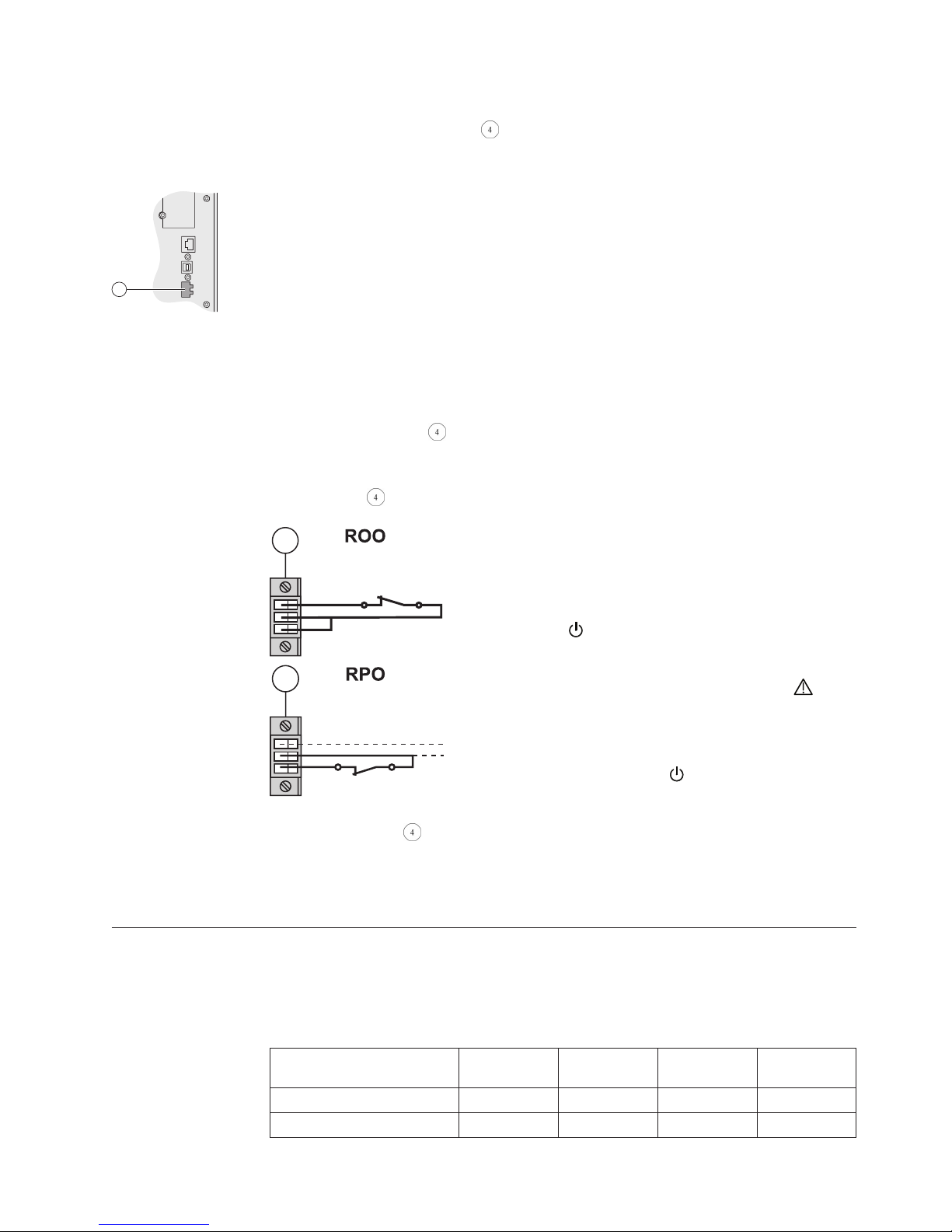
These functions are obtained by opening a contact connected between the
appropriate pins of connector
on the rear panel of the UPS (see the figures in
“Remote control connection and test”).
4
Remote control connection and test
Procedure
1. Check that the UPS is OFF and disconnected from the AC input source.
2. Remove connector
3. Connect a normally closed volt-free contact (60 V DC / 30 V AC max., 20 mA
max., 0.75 mm
connector
2
(see diagram).
4
4
.
(18 AWG) cable cross-section) between the two pins of
Contact open: UPS shutdown
Contact closed: UPS start-up (UPS connected
to AC power and AC power is available)
Note: The local ON/OFF control using the
button overrides the remote-control
function.
Contact open: UPS shutdown, LED goes
ON.
To return to normal operation, deactivate the
remote external contact and restart the UPS
by pressing the
button.
4. Plug connector into the back of the UPS.
5. Connect and restart the UPS following the previously described procedures.
6. Activate the external remote shutdown contact to test the function. This
connector must be connected only to Safety Extra-Low Voltage (SELV) circuits.
Operating modes: summary
The following table summarizes the characteristics of your UPS unit in each
operating mode.
Table 1. Operating modes
Mode Online Battery Standby
Load powered powered no power powered
Batteries charging discharging charging charging
High
Efficiency*
Chapter 5. Operation 25
Page 44

Table 1. Operating modes (continued)
High
Mode Online Battery Standby
Protection features:
Power failure yes n/a no yes
Power sag yes n/a no yes
Power surge yes n/a no yes
Under voltage yes n/a no yes
Over voltage yes n/a no yes
Efficiency*
Note: (*) High Efficiency mode introduces a delay between loss of input power
and switching to battery power.
26 Installation and User's Guide
Page 45

Chapter 6. UPS maintenance
Battery pack replacement
When the battery replacement screen is displayed (see illustration), replace the
battery packs. Contact your service representative to order new battery packs.
Load not powered
Battery replacement
-% 100%
4 years battery
Replacement is
-kW 100min
!
recommended
-kVA 1 EBM
OK
Replace all battery packs in the UPS and any EBMs connected to the UPS at the
same time. The replacement battery packs must have no more than 12 month
variation between their dates of manufacture and should not have reached or
exceeded their shelf life. Dispose of battery packs in accordance with local
regulations.
Battery packs can be replaced without turning off the UPS or disconnecting the
load. If you prefer to power down to change the battery packs, see Shutting down
the UPS.
Note: DO NOT DISCONNECT a battery pack while the UPS is in Battery mode.
Be aware the UPS can switch to Battery mode at any time and without warning.
Safety considerations
The battery packs can cause electrocution and high short-circuit currents. The
following safety precautions are required before servicing the battery components:
v Remove watches, rings, bracelets and all other metal objects from the hands and
arms
v Use tools with an insulated handle
Removing the battery tray on tower models
About this task
This operation must be performed when the UPS is switched OFF.
A
Remove the front panel.
© Copyright IBM Corp. 2014 27
Page 46

Disconnect the battery-module
B
by separating the town connectors
(never pull on the wires).
C
D
Mounting the new battery pack
Procedure
Carry out the instructions in “Removing the battery tray on tower models” on
page 27 in reverse order.
Note: To ensure safety and high performance, use only battery packs supplied by
IBM.
Remove the plastic protection
cover in front of the battery (one
screw).
Pull the plastic tab to remove
the battery block and replace it.
Important: Take care to firmly press together the two parts of the connector
during remounting.
28 Installation and User's Guide
Page 47

Chapter 7. Troubleshooting and maintenance
Alarms and faults
To check the Event log or Fault log:
1. Press any button on the front panel display to activate the menu options.
2. Press the
3. Press Enter (
button to select Event log or Fault log.
) to review the selected log.
4. Scroll through the listed events or faults.
The following table describes conditions that are logged.
Conditions Possible cause Action
Batteries disconnected
Overload
End of battery life
The UPS does not recognize the
internal battery packs.
The battery packs are not
connected.
Power requirement exceeds the
UPS capacity (greater than 105 %
of nominal).
The battery has reached
end-of-life.
If the condition persists, contact
your service representative.
Verify that all battery packs are
connected properly. If the
condition persists, contact your
service representative.
Remove some of the equipment
from the UPS. The UPS
continues to operate, but it
might shut down if the load
increases. The alarm resets when
the condition becomes inactive.
Contact your service
representative for battery-pack
replacement.
Event
UPS fault
© Copyright IBM Corp. 2014 29
A UPS event occurs.
Example: During remote Power
off, the RPO contact has been
activated to shut down the UPS
and now prevents restart.
An internal failure occurred.
Set the contact back to its normal
position and press the power (
) button to restart.
Record the alarm message and
the UPS serial number, then
contact your service
representative.
Page 48

Service and support
If you have any questions or problems with the UPS, call your Local Distributor or
your local service representative and ask for a UPS technical representative.
Have the following information ready when you call for service:
v Equipment type and model number
v Serial number
v Firmware version number
v Date of failure or problem
v Symptoms of failure or problem
v Customer address and contact information
If repair is required, you will be given a Returned Material Authorization (RMA)
number. This number must appear on the outside of the package and on the Bill
Of Lading (if applicable). Use the original packaging or request packaging from
your local service representative or distributor. Units damaged in shipment as a
result of improper packaging are not covered under warranty. A replacement or
repair unit will be shipped, freight prepaid for all warrantied units.
Note: For critical applications, immediate replacement might be available. Call
your local service representative or the distributor nearest you.
30 Installation and User's Guide
Page 49

Chapter 8. Parts listing
Replaceable components consist of consumable parts and field replaceable units
(FRUs):
v Consumable part: Purchase and replacement of consumable parts (components,
such as batteries and printer cartridges, that have depletable life) is your
responsibility. If IBM acquires or installs a consumable part at your request, you
will be charged for the service.
v Field replaceable unit (FRU): FRUs must be replaced only by a trained service
technician, unless they are classified as customer replaceable units (CRUs):
– Tier 1 customer replaceable unit (CRU): Replacement of Tier 1 CRUs is your
responsibility. If IBM installs a Tier 1 CRU at your request without a service
– Tier 2 customer replaceable unit: You may install a Tier 2 CRU yourself or
request IBM to install it, at no additional charge, under the type of warranty
service that is designated for your product.
For information about the terms of the warranty and getting service and assistance,
see the Warranty Information document.
Table 2. Parts listing table: Tower models
Description Type
Eaton 5P1000 120V Tower Tier 1
Eaton 5P1150i 230V Tower Tier 1
Eaton 5P1500 120V Tower Tier 1
Eaton 5P1550i 208V Tower Tier 1
5P1000, 5P1150i Battery Spare Tier 1
5P1500, 5P1550g Battery Spare Tier 1
5P Tower Bezel & Logos Spare Tier 1
Power Cord Part -- 5P P.C YH
AWG18*3 10A 250V C14C13
VDE 1.2M
CRU
CRU
CRU
CRU
CRU
CRU
CRU
Tier 1
CRU
Part
No.
00FP737 x
00FP738 x
00FP739 x
00FP741 x
00FP786 x x
00FP787 x x
00FP788 xxxx
00FP821 x x
5595-
1AX
5595-
1KX
5595-
2AX
5595-
2KX
© Copyright IBM Corp. 2014 31
Page 50

32 Installation and User's Guide
Page 51

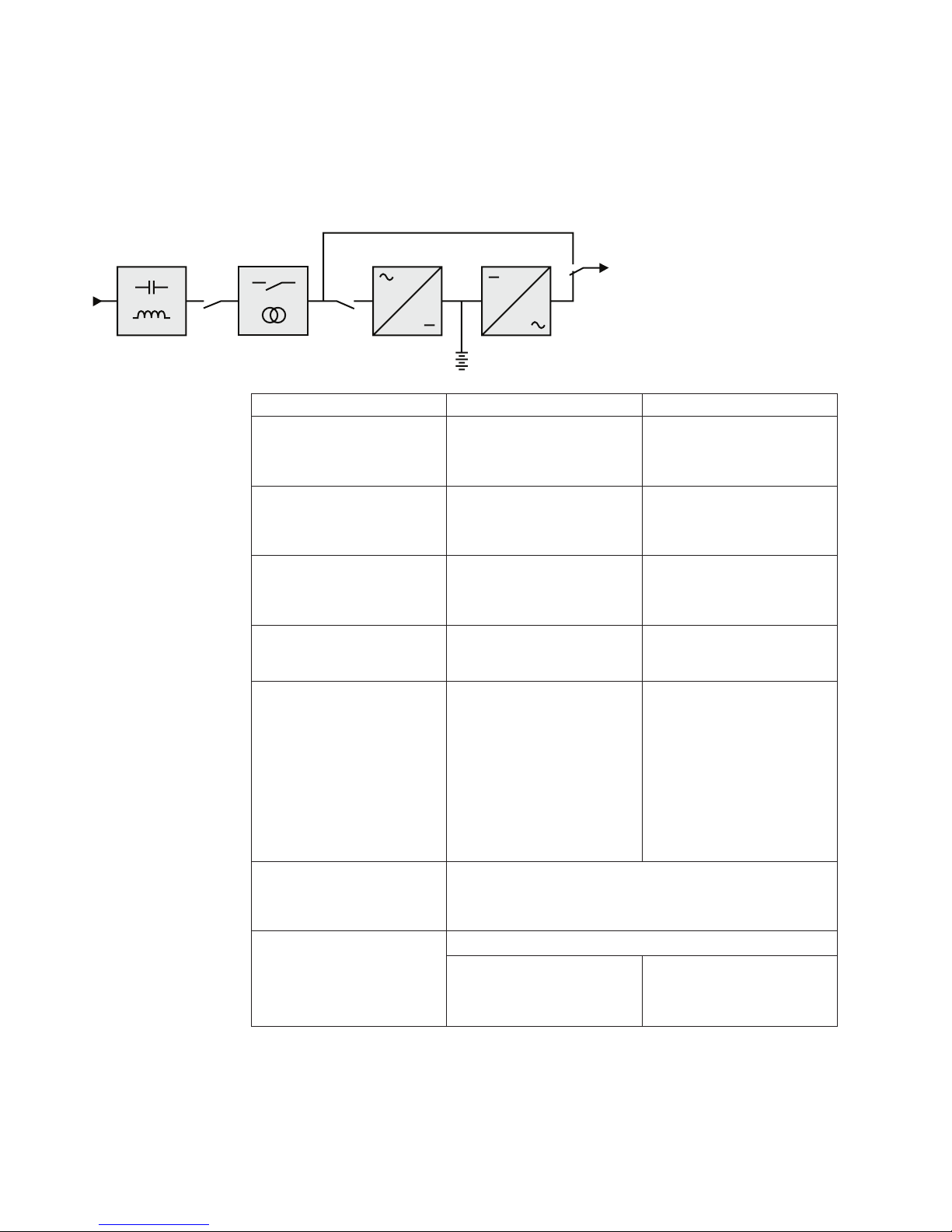
Appendix A. Technical specifications
5595-1AX 5595-2AX
Output Power @ 120 V
Output Power Capacity @
125 V
Output Power @ 100 V
1000 VA
1000 VA
770 W
770 W
833 VA
1440 VA
1100 W
1440 VA
1100 W
1080 VA
641 W
AC Input power
100-125VAC,50/
60Hz,1ph,8.8A max
AC Output power 50/60Hz,1ph;
100VAC,833VA,641W,8.4A;
120VAC,1000VA,770W,8.4A;
125VAC,1000VA,770W,8.4A
Output on battery power
v Voltage
v Frequency
100/120 V (-10/+6 %)
50/60 Hz ±0.1 Hz
Battery (sealed lead acid,
maintenance free)
v Standard
2x12V
9Ah
Environment Operating temperature: 0 to
+35 °C (32 to 95 °F)
Storage temperature: -15 to +50 °C (5 to 122 °F)
Relative humidity: 0 to 90 % (without condensation)
825 W
100-125VAC,50/
60Hz,1ph,12A max
50/60Hz,1ph;
100VAC,1080VA,825W,10.8A;
120VAC,1440VA,1100W,12A;
125VAC,1440VA,1100W,12A
(1)
3 x 12V
9Ah
Operating temperature: 0 to
+40 °C (32 to 104 °F)
(1) Adjustable to 100/120/125 V, must be set to the identical AC power source value.
© Copyright IBM Corp. 2014 33
Noise level: < 40 dBA
Page 52
Important: To reduce the risk of fire, the unit connects only to a circuit provided
with branch circuit overcurrent protection as described in this manual, in
accordance with the National Electric Code, ANSI/NFPA 70.
This product is designed for IT power distribution systems.
5595-1KX 5595-2KX
Output Power @ 230 V
Output Power Capacity @
208 V
Output Power @ 200 V
1150 VA
770 W
1035 VA
693 W
1035 VA
1550 VA
1100 W
1395 VA
990 W
1395 VA
AC Input power
AC Output power 50/60Hz,1ph;
Output on battery power
v Voltage
v Frequency
Battery (sealed lead acid,
maintenance free)
v Standard
200-240VAC,50/
60Hz,1ph,5.3A max
200VAC,1035VA,693W,5.2A;
208VAC,1035VA,693W,5.2A;
220VAC,1150VA,770W,5.3A;
230VAC,1150VA,770W,5.3A;
240VAC,1150VA,770W,5.3A
2x12V
693 W
200-240VAC,50/
60Hz,1ph,7.1A max
50/60Hz,1ph;
200VAC,1395VA,990W,7A;
208VAC,1395VA,990W,7A;
220VAC,1550VA,1100W,7.1A;
230VAC,1550VA,1100W,7.1A;
240VAC,1550VA,1100W,7.1A
200/208/220/230/240 V (-10/+6 %)
50/60 Hz ±0.1 Hz
Tower
9Ah
990 W
3 x 12V
9Ah
(1)
34 Installation and User's Guide
Page 53

5595-1KX 5595-2KX
Environment
v Operating temperature
range
v Storage temperature range
v Relative humidity
v Noise level
(1) Adjustable to 200/208/220/230/240 V, must be set to the identical AC power source value.
0 to +35 °C 0 to +40 °C
-15 to +50 °C
20 to 90 % (without condensation)
<40dBA
When the appliance is used in the EU, use an external circuit breaker in front of
line with rating 16 A, 250 V which is IEC/EN 60898-1 standard compliant.
When the appliance is used in American area, use an external circuit breaker in
front of line with rating 20 A, 250 V.
This product is designed for IT power distribution systems.
Appendix A. Technical specifications 35
Page 54

36 Installation and User's Guide
Page 55

Appendix B. Getting help and technical assistance
If you need help, service, or technical assistance or just want more information
about IBM products, you will find a wide variety of sources available from IBM to
assist you.
Use this information to obtain additional information about IBM and IBM
products, determine what to do if you experience a problem with your IBM system
or optional device, and determine whom to call for service, if it is necessary.
Before you call
Before you call, make sure that you have taken these steps to try to solve the
problem yourself.
If you believe that you require IBM to perform warranty service on your IBM
product, the IBM service technicians will be able to assist you more efficiently if
you prepare before you call.
v Check all cables to make sure that they are connected.
v Check the power switches to make sure that the system and any optional
devices are turned on.
v Check for updated software, firmware, and operating-system device drivers for
your IBM product. The IBM Warranty terms and conditions state that you, the
owner of the IBM product, are responsible for maintaining and updating all
software and firmware for the product (unless it is covered by an additional
maintenance contract). Your IBM service technician will request that you
upgrade your software and firmware if the problem has a documented solution
within a software upgrade.
v If you have installed new hardware or software in your environment, check
http://www.ibm.com/systems/info/x86servers/serverproven/compat/us to
make sure that the hardware and software is supported by your IBM product.
v Go to http://www.ibm.com/supportportal to check for information to help you
solve the problem.
v Gather the following information to provide to IBM Support. This data will help
IBM Support quickly provide a solution to your problem and ensure that you
receive the level of service for which you might have contracted.
– Hardware and Software Maintenance agreement contract numbers, if
applicable
– Machine type number (IBM 4-digit machine identifier)
– Model number
– Serial number
– Current system UEFI and firmware levels
– Other pertinent information such as error messages and logs
v Go to http://www.ibm.com/support/entry/portal/Open_service_request to
submit an Electronic Service Request. Submitting an Electronic Service Request
will start the process of determining a solution to your problem by making the
pertinent information available to IBM Support quickly and efficiently. IBM
service technicians can start working on your solution as soon as you have
completed and submitted an Electronic Service Request.
© Copyright IBM Corp. 2014 37
Page 56

Using the documentation
Information about your IBM system and preinstalled software, if any, or optional
device is available in the documentation that comes with the product. That
documentation can include printed documents, online documents, readme files,
and help files.
See the troubleshooting information in your system documentation for instructions
for using the diagnostic programs. The troubleshooting information or the
diagnostic programs might tell you that you need additional or updated device
drivers or other software. IBM maintains pages on the World Wide Web where you
can get the latest technical information and download device drivers and updates.
To access these pages, go to http://www.ibm.com/supportportal.
Getting help and information from the World Wide Web
Up-to-date information about IBM products and support is available on the World
Wide Web.
On the World Wide Web, up-to-date information about IBM systems, optional
devices, services, and support is available at http://www.ibm.com/supportportal.
How to send DSA data to IBM
Use the IBM Enhanced Customer Data Repository to send diagnostic data to IBM.
Before you send diagnostic data to IBM, read the terms of use at
http://www.ibm.com/de/support/ecurep/terms.html.
You can use any of the following methods to send diagnostic data to IBM:
v Standard upload:http://www.ibm.com/de/support/ecurep/send_http.html
v Standard upload with the system serial number: http://www.ecurep.ibm.com/
app/upload_hw
v Secure upload: http://www.ibm.com/de/support/ecurep/
send_http.html#secure
v Secure upload with the system serial number: https://www.ecurep.ibm.com/
app/upload_hw
Software service and support
Through IBM Support Line, you can get telephone assistance, for a fee, with usage,
configuration, and software problems with your IBM products.
For more information about Support Line and other IBM services, see
http://www.ibm.com/services or see http://www.ibm.com/planetwide for
support telephone numbers. In the U.S. and Canada, call 1-800-IBM-SERV
(1-800-426-7378).
Hardware service and support
You can receive hardware service through your IBM reseller or IBM Services.
38 Installation and User's Guide
Page 57

To locate a reseller authorized by IBM to provide warranty service, go to
http://www.ibm.com/partnerworld/pwhome.nsf/weblook/index_us.html and
click Business Partner Locator. For IBM support telephone numbers, see
http://www.ibm.com/planetwide. In the U.S. and Canada, call 1-800-IBM-SERV
(1-800-426-7378).
In the U.S. and Canada, hardware service and support is available 24 hours a day,
7 days a week. In the U.K., these services are available Monday through Friday,
from 9 a.m. to 6 p.m.
IBM Taiwan product service
Use this information to contact IBM Taiwan product service.
IBM Taiwan product service contact information:
IBM Taiwan Corporation
3F, No 7, Song Ren Rd.
Taipei, Taiwan
Telephone: 0800-016-888
Appendix B. Getting help and technical assistance 39
Page 58

40 Installation and User's Guide
Page 59

Appendix C. Notices
This information was developed for products and services offered in the U.S.A.
IBM may not offer the products, services, or features discussed in this document in
other countries. Consult your local IBM representative for information on the
products and services currently available in your area. Any reference to an IBM
product, program, or service is not intended to state or imply that only that IBM
product, program, or service may be used. Any functionally equivalent product,
program, or service that does not infringe any IBM intellectual property right may
be used instead. However, it is the user's responsibility to evaluate and verify the
operation of any non-IBM product, program, or service.
IBM may have patents or pending patent applications covering subject matter
described in this document. The furnishing of this document does not give you
any license to these patents. You can send license inquiries, in writing, to:
IBM Director of Licensing
IBM Corporation
North Castle Drive
Armonk, NY 10504-1785
U.S.A.
INTERNATIONAL BUSINESS MACHINES CORPORATION PROVIDES THIS
PUBLICATION “AS IS” WITHOUT WARRANTY OF ANY KIND, EITHER
EXPRESS OR IMPLIED, INCLUDING, BUT NOT LIMITED TO, THE IMPLIED
WARRANTIES OF NON-INFRINGEMENT, MERCHANTABILITY OR FITNESS
FOR A PARTICULAR PURPOSE. Some states do not allow disclaimer of express or
implied warranties in certain transactions, therefore, this statement may not apply
to you.
This information could include technical inaccuracies or typographical errors.
Changes are periodically made to the information herein; these changes will be
incorporated in new editions of the publication. IBM may make improvements
and/or changes in the product(s) and/or the program(s) described in this
publication at any time without notice.
Any references in this information to non-IBM websites are provided for
convenience only and do not in any manner serve as an endorsement of those
websites. The materials at those websites are not part of the materials for this IBM
product, and use of those websites is at your own risk.
IBM may use or distribute any of the information you supply in any way it
believes appropriate without incurring any obligation to you.
Trademarks
IBM, the IBM logo, and ibm.com are trademarks of International Business
Machines Corp., registered in many jurisdictions worldwide. Other product and
service names might be trademarks of IBM or other companies.
A current list of IBM trademarks is available on the web at http://www.ibm.com/
legal/us/en/copytrade.shtml.
© Copyright IBM Corp. 2014 41
Page 60

Important notes
Linux is a registered trademark of Linus Torvalds in the United States, other
countries, or both.
Microsoft, Windows, and Windows NT are trademarks of Microsoft Corporation in
the United States, other countries, or both.
Processor speed indicates the internal clock speed of the microprocessor; other
factors also affect application performance.
CD or DVD drive speed is the variable read rate. Actual speeds vary and are often
less than the possible maximum.
When referring to processor storage, real and virtual storage, or channel volume,
KB stands for 1024 bytes, MB stands for 1,048,576 bytes, and GB stands for
1,073,741,824 bytes.
When referring to hard disk drive capacity or communications volume, MB stands
for 1,000,000 bytes, and GB stands for 1,000,000,000 bytes. Total user-accessible
capacity can vary depending on operating environments.
Maximum internal hard disk drive capacities assume the replacement of any
standard hard disk drives and population of all hard disk drive bays with the
largest currently supported drives that are available from IBM.
Maximum memory might require replacement of the standard memory with an
optional memory module.
Each solid-state memory cell has an intrinsic, finite number of write cycles that the
cell can incur. Therefore, a solid-state device has a maximum number of write
cycles that it can be subjected to, expressed as total bytes written (TBW). A
device that has exceeded this limit might fail to respond to system-generated
commands or might be incapable of being written to. IBM is not responsible for
replacement of a device that has exceeded its maximum guaranteed number of
program/erase cycles, as documented in the Official Published Specifications for
the device.
IBM makes no representation or warranties regarding non-IBM products and
services that are ServerProven
of merchantability and fitness for a particular purpose. These products are offered
and warranted solely by third parties.
IBM makes no representations or warranties with respect to non-IBM products.
Support (if any) for the non-IBM products is provided by the third party, not IBM.
Some software might differ from its retail version (if available) and might not
include user manuals or all program functionality.
Particulate contamination
®
, including but not limited to the implied warranties
Attention: Airborne particulates (including metal flakes or particles) and reactive
gases acting alone or in combination with other environmental factors such as
humidity or temperature might pose a risk to the device that is described in this
document.
42 Installation and User's Guide
Page 61

Risks that are posed by the presence of excessive particulate levels or
concentrations of harmful gases include damage that might cause the device to
malfunction or cease functioning altogether. This specification sets forth limits for
particulates and gases that are intended to avoid such damage. The limits must not
be viewed or used as definitive limits, because numerous other factors, such as
temperature or moisture content of the air, can influence the impact of particulates
or environmental corrosives and gaseous contaminant transfer. In the absence of
specific limits that are set forth in this document, you must implement practices
that maintain particulate and gas levels that are consistent with the protection of
human health and safety. If IBM determines that the levels of particulates or gases
in your environment have caused damage to the device, IBM may condition
provision of repair or replacement of devices or parts on implementation of
appropriate remedial measures to mitigate such environmental contamination.
Implementation of such remedial measures is a customer responsibility.
Table 3. Limits for particulates and gases
Contaminant Limits
Particulate
Gaseous
1
ASHRAE 52.2-2008 - Method of Testing General Ventilation Air-Cleaning Devices for
Removal Efficiency by Particle Size. Atlanta: American Society of Heating, Refrigerating
and Air-Conditioning Engineers, Inc.
2
The deliquescent relative humidity of particulate contamination is the relative
humidity at which the dust absorbs enough water to become wet and promote ionic
conduction.
3
ANSI/ISA-71.04-1985. Environmental conditions for process measurement and control
systems: Airborne contaminants. Instrument Society of America, Research Triangle Park,
North Carolina, U.S.A.
v The room air must be continuously filtered with 40% atmospheric dust
spot efficiency (MERV 9) according to ASHRAE Standard 52.2
v Air that enters a data center must be filtered to 99.97% efficiency or
greater, using high-efficiency particulate air (HEPA) filters that meet
MIL-STD-282.
v The deliquescent relative humidity of the particulate contamination
must be more than 60%
v The room must be free of conductive contamination such as zinc
whiskers.
v Copper: Class G1 as per ANSI/ISA 71.04-1985
v Silver: Corrosion rate of less than 300 Å in 30 days
2
.
3
1
.
Telecommunication regulatory statement
This product may not be certified in your country for connection by any means
whatsoever to interfaces of public telecommunications networks. Further
certification may be required by law prior to making any such connection. Contact
an IBM representative or reseller for any questions.
Electronic emission notices
When you attach a monitor to the equipment, you must use the designated
monitor cable and any interference suppression devices that are supplied with the
monitor.
Appendix C. Notices 43
Page 62

Federal Communications Commission (FCC) statement
Note: This equipment has been tested and found to comply with the limits for a
Class A digital device, pursuant to Part 15 of the FCC Rules. These limits are
designed to provide reasonable protection against harmful interference when the
equipment is operated in a commercial environment. This equipment generates,
uses, and can radiate radio frequency energy and, if not installed and used in
accordance with the instruction manual, may cause harmful interference to radio
communications. Operation of this equipment in a residential area is likely to cause
harmful interference, in which case the user will be required to correct the
interference at his own expense.
Properly shielded and grounded cables and connectors must be used in order to
meet FCC emission limits. IBM is not responsible for any radio or television
interference caused by using other than recommended cables and connectors or by
unauthorized changes or modifications to this equipment. Unauthorized changes
or modifications could void the user's authority to operate the equipment.
This device complies with Part 15 of the FCC Rules. Operation is subject to the
following two conditions: (1) this device may not cause harmful interference, and
(2) this device must accept any interference received, including interference that
might cause undesired operation.
Industry Canada Class A emission compliance statement
This Class A digital apparatus complies with Canadian ICES-003.
Avis de conformité à la réglementation d'Industrie Canada
Cet appareil numérique de la classe A est conforme à la norme NMB-003 du
Canada.
Australia and New Zealand Class A statement
Attention: This is a Class A product. In a domestic environment this product may
cause radio interference in which case the user may be required to take adequate
measures.
European Union EMC Directive conformance statement
This product is in conformity with the protection requirements of EU Council
Directive 2004/108/EC on the approximation of the laws of the Member States
relating to electromagnetic compatibility. IBM cannot accept responsibility for any
failure to satisfy the protection requirements resulting from a nonrecommended
modification of the product, including the fitting of non-IBM option cards.
Attention: This is an EN 55022 Class A product. In a domestic environment this
product may cause radio interference in which case the user may be required to
take adequate measures.
Responsible manufacturer:
International Business Machines Corp.
New Orchard Road
Armonk, New York 10504
914-499-1900
European Community contact:
44 Installation and User's Guide
Page 63

IBM Deutschland GmbH
Technical Regulations, Department M372
IBM-Allee 1, 71139 Ehningen, Germany
Telephone: +49 7032 15 2941
Email: lugi@de.ibm.com
Germany Class A statement
Deutschsprachiger EU Hinweis: Hinweis für Geräte der Klasse A EU-Richtlinie
zur Elektromagnetischen Verträglichkeit
Dieses Produkt entspricht den Schutzanforderungen der EU-Richtlinie
2004/108/EG zur Angleichung der Rechtsvorschriften über die elektromagnetische
Verträglichkeit in den EU-Mitgliedsstaaten und hält die Grenzwerte der EN 55022
Klasse A ein.
Um dieses sicherzustellen, sind die Geräte wie in den Handbüchern beschrieben zu
installieren und zu betreiben. Des Weiteren dürfen auch nur von der IBM
empfohlene Kabel angeschlossen werden. IBM übernimmt keine Verantwortung für
die Einhaltung der Schutzanforderungen, wenn das Produkt ohne Zustimmung der
IBM verändert bzw. wenn Erweiterungskomponenten von Fremdherstellern ohne
Empfehlung der IBM gesteckt/eingebaut werden.
EN 55022 Klasse A Geräte müssen mit folgendem Warnhinweis versehen werden:
Warnung: Dieses ist eine Einrichtung der Klasse A. Diese Einrichtung kann im
Wohnbereich Funk-Störungen verursachen; in diesem Fall kann vom Betreiber
verlangt werden, angemessene Maßnahmen zu ergreifen und dafür aufzukommen.
Deutschland: Einhaltung des Gesetzes über die
elektromagnetische Verträglichkeit von Geräten
Dieses Produkt entspricht dem Gesetz über die elektromagnetische Verträglichkeit
von Geräten (EMVG). Dies ist die Umsetzung der EU-Richtlinie 2004/108/EG in
der Bundesrepublik Deutschland.
Zulassungsbescheinigung laut dem Deutschen Gesetz über die
elektromagnetische Verträglichkeit von Geräten (EMVG) (bzw. der
EMC EG Richtlinie 2004/108/EG) für Geräte der Klasse A
Dieses Gerät ist berechtigt, in Übereinstimmung mit dem Deutschen EMVG das
EG-Konformitätszeichen - CE - zu führen.
Verantwortlich für die Einhaltung der EMV Vorschriften ist der Hersteller:
International Business Machines Corp.
New Orchard Road
Armonk, New York 10504
914-499-1900
Der verantwortliche Ansprechpartner des Herstellers in der EU ist:
IBM Deutschland GmbH
Technical Regulations, Abteilung M372
IBM-Allee 1, 71139 Ehningen, Germany
Telephone: +49 7032 15 2941
Email: lugi@de.ibm.com
Appendix C. Notices 45
Page 64
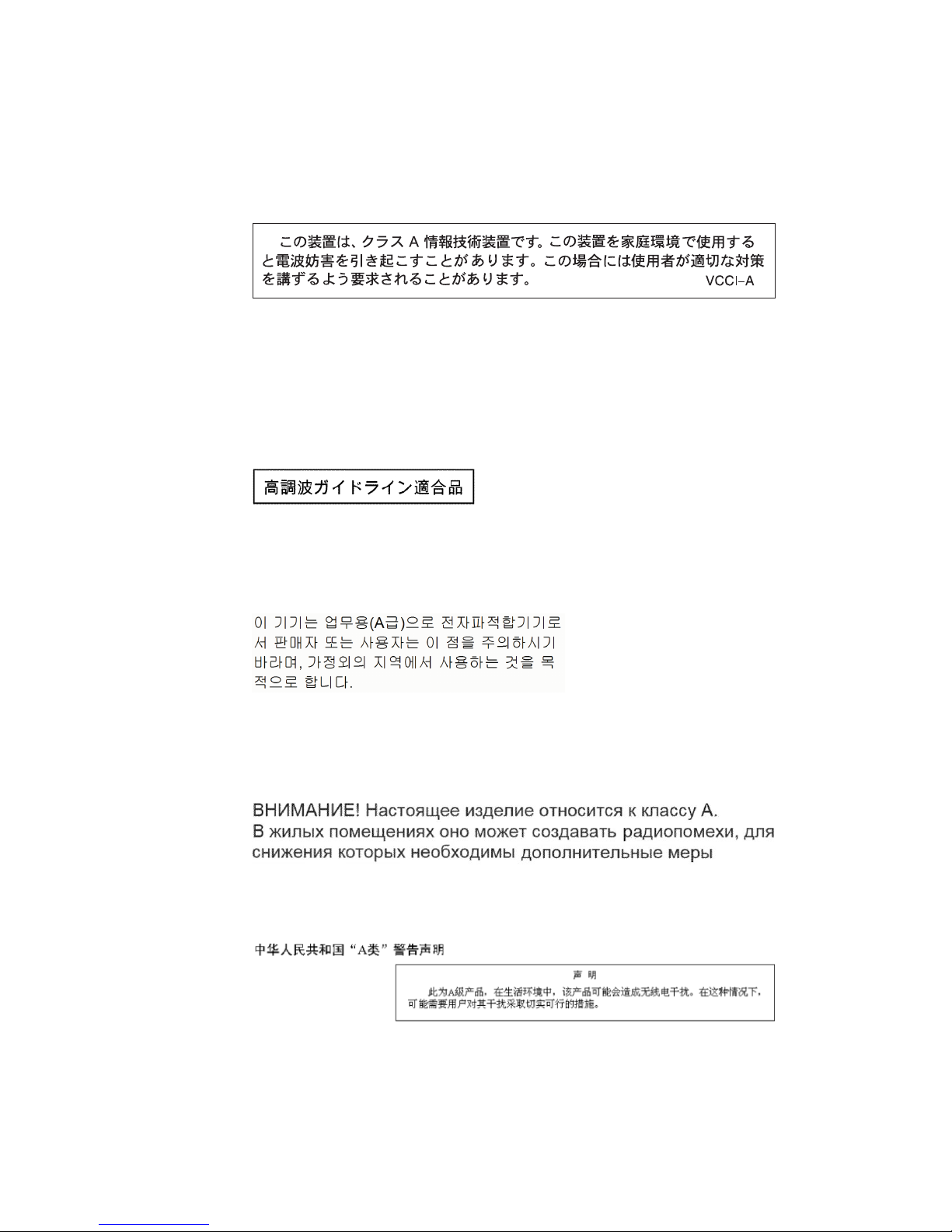
Generelle Informationen:
Das Gerät erfüllt die Schutzanforderungen nach EN 55024 und EN 55022 Klasse
A.
Japan VCCI Class A statement
This is a Class A product based on the standard of the Voluntary Control Council
for Interference (VCCI). If this equipment is used in a domestic environment, radio
interference may occur, in which case the user may be required to take corrective
actions.
Japan Electronics and Information Technology Industries
Association (JEITA) statement
Japan Electronics and Information Technology Industries Association (JEITA)
Confirmed Harmonics Guidelines (products less than or equal to 20 A per phase)
Korea Communications Commission (KCC) statement
This is electromagnetic wave compatibility equipment for business (Type A). Sellers
and users need to pay attention to it. This is for any areas other than home.
Russia Electromagnetic Interference (EMI) Class A statement
People's Republic of China Class A electronic emission
statement
46 Installation and User's Guide
Page 65

Taiwan Class A compliance statement
Appendix C. Notices 47
Page 66

48 Installation and User's Guide
Page 67

Appendix D. Glossary
Advanced Battery Management (ABM)
A three-stage charging system designed to prolong the service life of IBM
UPS batteries. By charging the batteries only when necessary, battery life is
significantly improved. Charging stage one: quickly recharges battery to
approximately 90% of capacity. Charging stage two: fully charges the
battery to 100%. Charging stage three: rest mode prevents overcharging.
Charging stage one is initiated after a power outage or periodic UPS
self-test.
Backup time
Time during which the load can be supplied by the UPS operating on
battery power.
Battery test
Internal UPS test to check battery status.
Cold start
The devices connected to the UPS can be started even if AC input power is
not available. The UPS operates on battery power alone.
Deep discharge
Battery discharge beyond the permissible limit, resulting in irreversible
damage to the battery.
Load Devices or equipment connected to the UPS output.
Low-battery warning
A battery level indicating that battery power is low and that action should
be taken to prevent the imminent disruption of power to the load.
Normal AC input
The AC-power line supplying the UPS under normal conditions.
Percent load
Ratio of the power effectively drawn by the load to the maximum output
of the UPS.
Personalisation
It is possible to modify certain UPS parameters set in the factory. Certain
UPS functions can also be modified by the software to better suit user
needs.
Programmable outlets
Controllable outlets for automatic load shedding, remote shutdown and
sequential restart (personalized using software).
UPS Uninterruptible Power System.
UPS ON/OFF controlled by software
This function enables or disables initiation of UPS ON/OFF control
sequences by computer power-management software.
© Copyright IBM Corp. 2014 49
Page 68

50 Installation and User's Guide
Page 69

Page 70

Part Number: 47C9195
Printed in USA
(1P) P/N: 47C9195
 Loading...