

Page 1

-
-
- -
-
-
- - -
-
- _.-
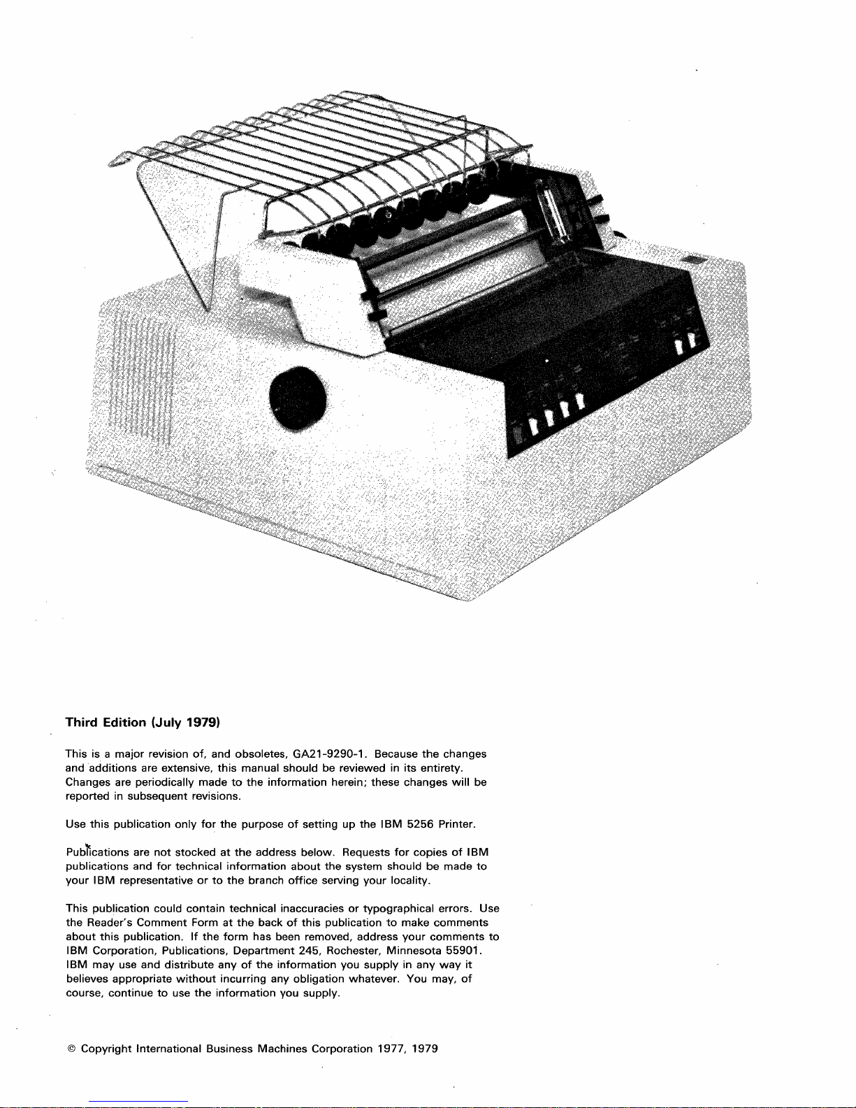
IBM 5256 Printer
Setup Procedure
--
--
---
--
---
---
---
GA21-9290-2
File No. S5250/S34/S38-00
Page 2
Third Edition (July 1979)
This
is a
major
and
additions
Changes are
reported in
this
Use
publication
revision
are extensive,
periodically
subsequent
of,
made
revisions.
only
for
and obsoletes,
this
the
manual
to
the
purpose
GA21-9290-1.
should
information
of
setting
Because
be reviewed in
herein;
these
up
the
IBM
the
its
entirety.
changes
5256
Printer.
changes
will
be
Pub~cations
publications
your
This
the
Reader's
about
IBM
IBM
believes
course,
©
Copyright
are
and
IBM
representative
publication
Comment
this
publication.
Corporation,
may
use and
appropriate
continue
International
not
stocked
for
technical
or
could
contain
Form
If
the
Publications,
distribute
without
to
use
the
at
the
information
to
the
technical
at
the
form
Department
any
of
incurring
information
Business
address
branch
office
inaccuracies
back
of
has been removed,
the
information
any
you supply.
Machines
below.
about
245, Rochester,
obligation
Requests
the
serving
this
publication
you
Corporation
system
or
whatever.
for
should
your
locality.
typographical
to
make
address
Minnesota
supply
1977,
your
in
You may,
1979
copies
be
errors. Use
comments
comments
any
way
of
IBM
made
55901.
it
of
to
to
Page 3

Section
1.
Setting
Up
the
Printer
Safety
pounds).
This
unpacked and
been
in its
Before
Precaution:
Never
setup
and
disconnected
proper
you continue,
If
you
do
back
of
your
must
be
the
line
or
the
lift
it
checkout
placed
and relocated.
location.
not
have
printer,
only
last
machine
The
5256
by
yourself.
procedure
where
look
at
switches
your
machine
on a line.
Printer weighs
should
you
intend
It
is
the
back
of
on
the
printer
on a
approx
be used
to
use
it
important
the
printer.
imately
or
whenever a printer
to
after
ensure
36
kilograms (78
your
printer
that
If
you
are
white,
which
your
printer
_!.
~
has been
has
your
printer
have
and a
is blue, on
is
Address
can be placed
switches,
Terminator
the
back
of
anywhere
4'
f.~,
UI;'/)~_
_
Address Switches
which
switch,
your
printer,
on a line.
If
in
doubt,
manager.
Now
do
check
the
with
following
someone
procedure
such as
to
set
your
up
supervisor,
your
printer
and
system
make
~~
~~~
1
operator,
it
operative.
Terminator
or
Switch
Setting
Up
the
Printer
1-1
Page 4
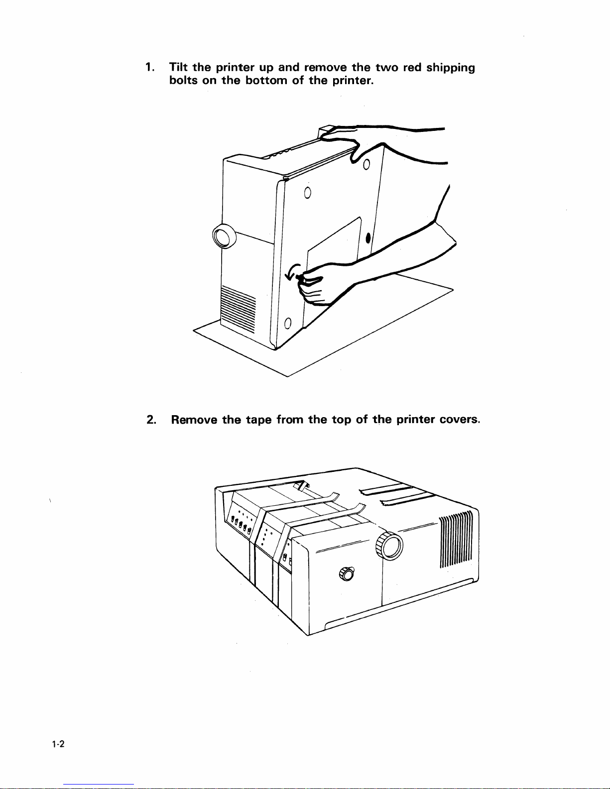
1.
Tilt
bolts
the
on
printer
the
bottom
up
and
of
remove
the
printer.
the
two
red
shipping
2.
Remove
the
tape
from
the
top
of
the
printer
covers.
0)))))111
1-2
Page 5
3.
Top
Slide
Cover
the
top
cover
open.
4.
Carefully
Then
the
gently
printer.
remove
push
the
the
tape
print
from
head
the
to
Print
print
the
Head
head.
left
side
of
5.
Close
the
top
cover.
Setting Up the Printer 1-3
Page 6

6.
Remove
the
machine.
from
cord
the
yet.
the
power
power
Cut
cord.
cord
and
from
remove
DO
NOT
the
the
plug
slot
at
plastic
in
the
the
rear
string
power
of
7.
Open
the
remove
carton.
carton
the
maintenance
that
Remove power cord
came
with
documentation
the
from
under here.
printer
from
and
the
1-4
Page 7
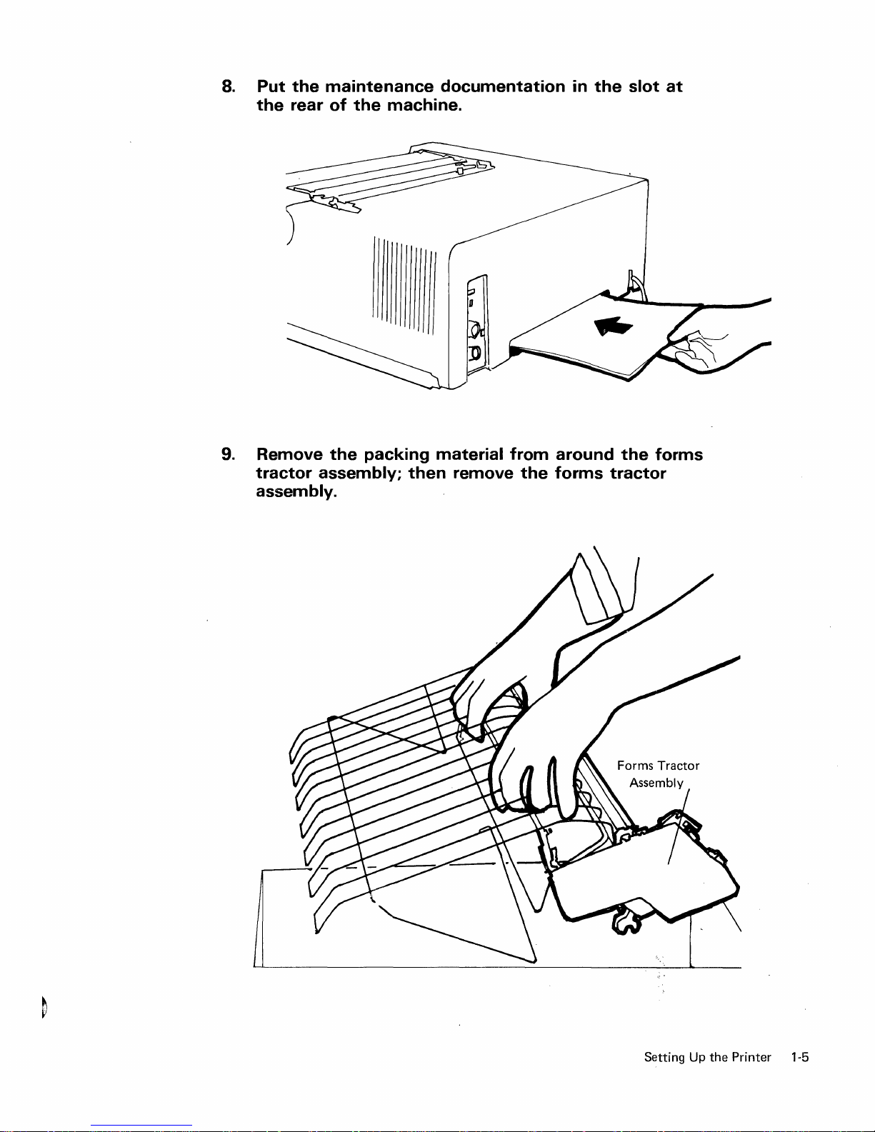
8.
Put
the
9.
Remove
tractor
assembly.
the
maintenance
rear
of
the
assembly;
the
machine.
packing
documentation
material
then
remove
from
the
in
the
around
forms
slot
the
forms
tractor
at
Setting Up
the
Printer 1-5
Page 8
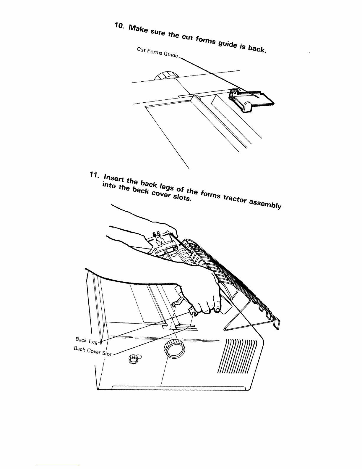
11.
10.
.Insert
'Oto
the
Make
the
back
SUre
CUt Forms GUide
back
cOver Slots.
the
legS
of
CUt
the
forms
forms
gUide
tractor
is
baCk.
aSSfJlnbl)l
Page 9

12.
Press
down firmly until the back
the forms tractor toward the front
snap
into place.
legs
snap
into place. Then pivot
of
the printer until the front
legs
III)))))
13. Check the final placement by making
freely
and
turn
the tractor
pins
move.
sure
the Paper Advance knobs
_
Paper
Knob
Advance
Setti
ng Up
the
Pri
nter
1-7
Page 10
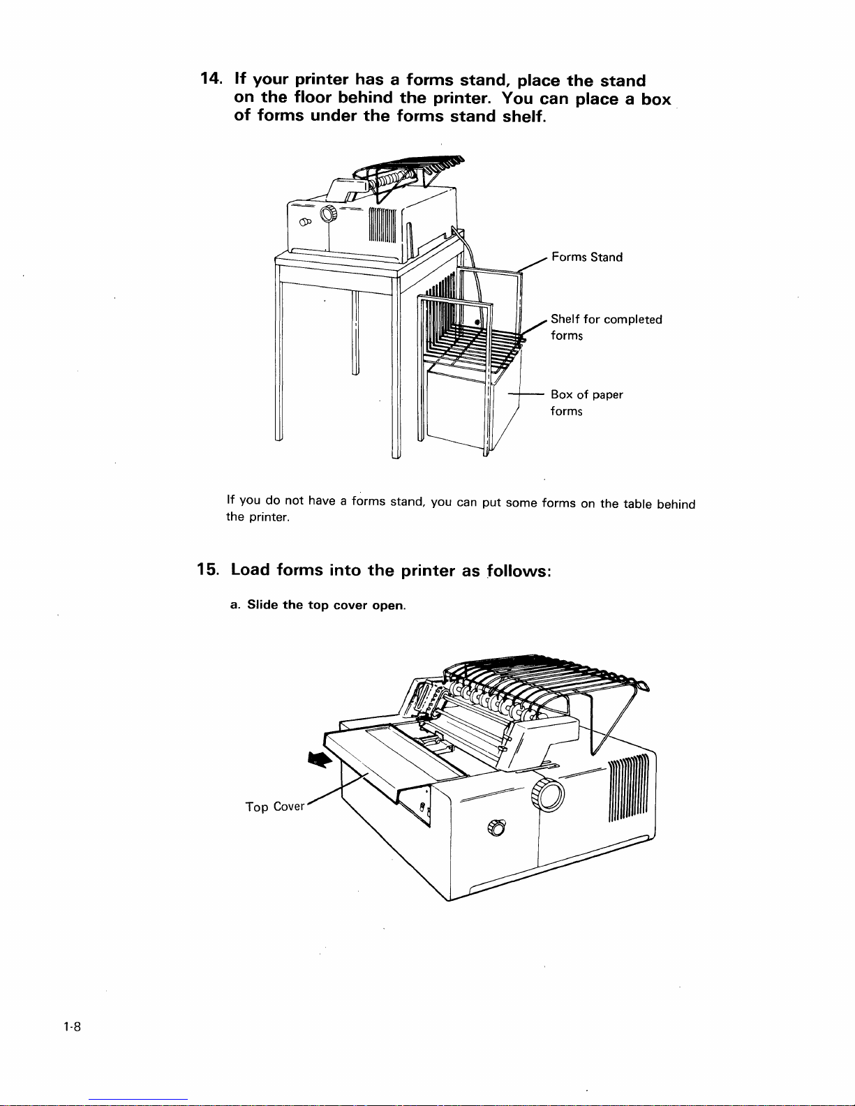
14.
If
your printer has a forms stand, place
on
the
floor behind
of
forms under
the
printer. You can place a
the
forms stand shelf.
the
stand
Forms Stand
for
of
paper
completed
Shelf
forms
Box
forms
box
15.
If
you
the
printer.
load
a. Slide
Top
do
not
have a
forms into
the
top
Cover
forms
cover
stand,
you
can
the
printer as follows:
open.
put
some
forms
on
the
table
behind
1-8
Page 11
b.
Push
the
paper
release
lever
toward
the
back
of
the
printer.
c.
Squeeze
it
to
the
the
right
adjusting
as
far
as
levers
it
will
on
go.
the
right
forms
tractor
and
slide
Setting
Up
the
Printer
1-9
Page 12

d. 'Tilt
the
forms
e.
Slide
guide
the
racl<
paper
up·
over
the
rollers.
1-10
Page 13
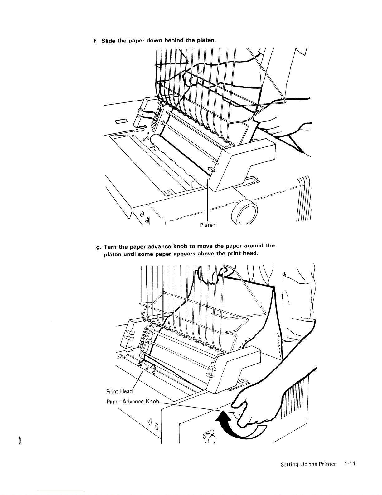
f.
Slide
the
paper
down
behind
the
platen.
g.
Turn
platen
the
paper
until
advance
some
paper
knob
to
appears
move
above
the
the
paper
print
around
head.
the
Setting
Up
the
Printer
1-11
Page 14

h.
Tilt
the
i.
forms
Open
guide
rack
both
tractor covers.
down.
1-12
Tractor covers
Page 15
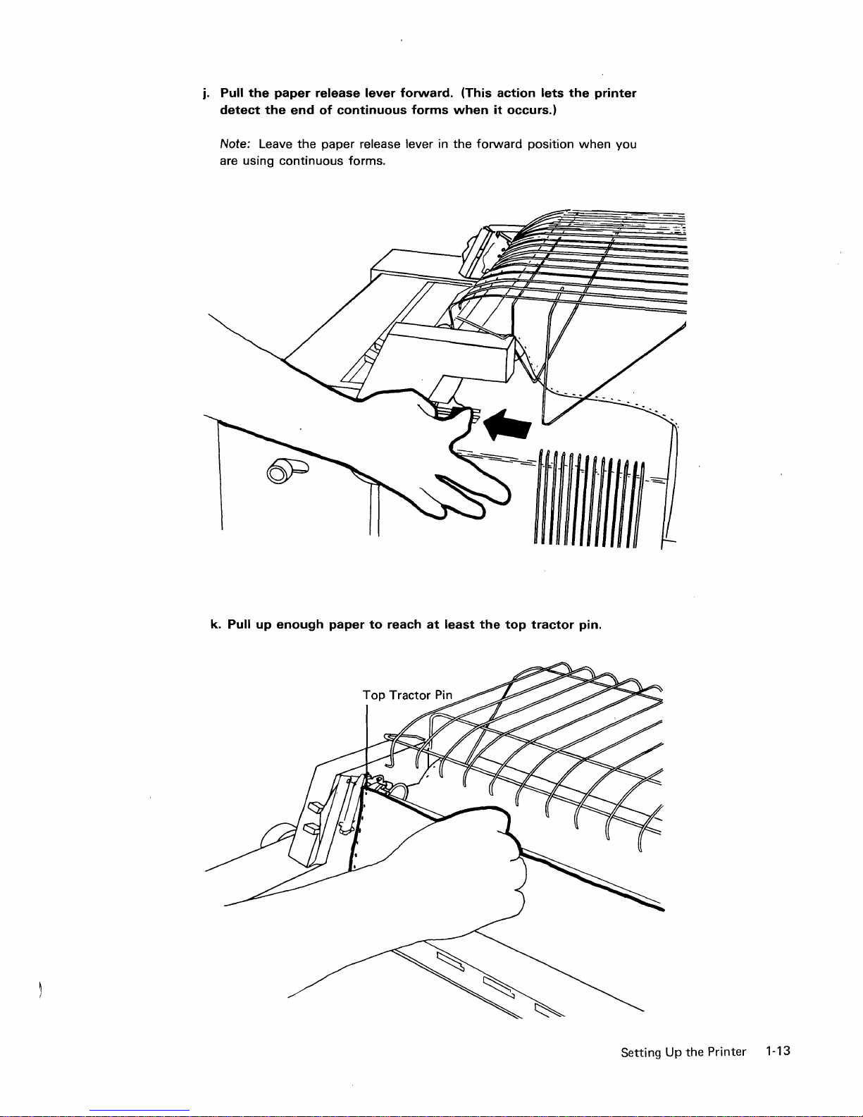
j.
Pull
the
detect
paper
the
end
release
of
continuous
lever
forward.
forms
(This
when
action
it
occurs.)
lets
the
printer
Note: Leave
are using
continuous
the
paper release lever in
forms.
the
forward
position
when
you
k.
Pull
up
enough
paper
to
reach
at
least
the
top
tractor
pin.
Setting
Up
the Printer 1-13
Page 16

I.
Place
the
m.
Squeeze
it
right
the
left
to
paper
the
tractor
the
the
left
tractor
left
margin
adjusting
until
pins.
are
positioned
cover.
the
(Make
holes
levers
right
sure
so
over
the
on
the
margin
the
that
left
right
holes
margin
the
tractor
can
paper
forms
be
holes
is
level.)
pins;
tractor
placed
in
each
then
and
over
side
close'
slide
the
of
n.
Close
the
right
paper
by
sliding
o.
Close
the
top
1-14
tractor
the
cover.
cover.
right
Remove
forms
tractor
any
left
slack
or
or
right.
bulges
in
the
Page 17

16.
Make
sure
the
O
Power
Power 0
On
switch
Ready
is
set
O
Line
Sync
to
Off.
2
O
System
Available
17.
Power
Don
•
Make
4 5
Storage
Check
O
o
Attention
o
Forms
Unit
.
Check
O
Off
sure
Stop
Start
Line
Feed
D D D
the
Status
0 Internal
Check
switch
6
GraPhiC
Check
O
is
set
Line
Spacing
0:
Form
Feed
D
to
Nonnal.
8
O
Status
8
Transparent
Mode
Cancel
Normal
Test
18. Plug in
the
power
cord.
Setti
ng
Up
the
Pri
nter
1-15
Page 18
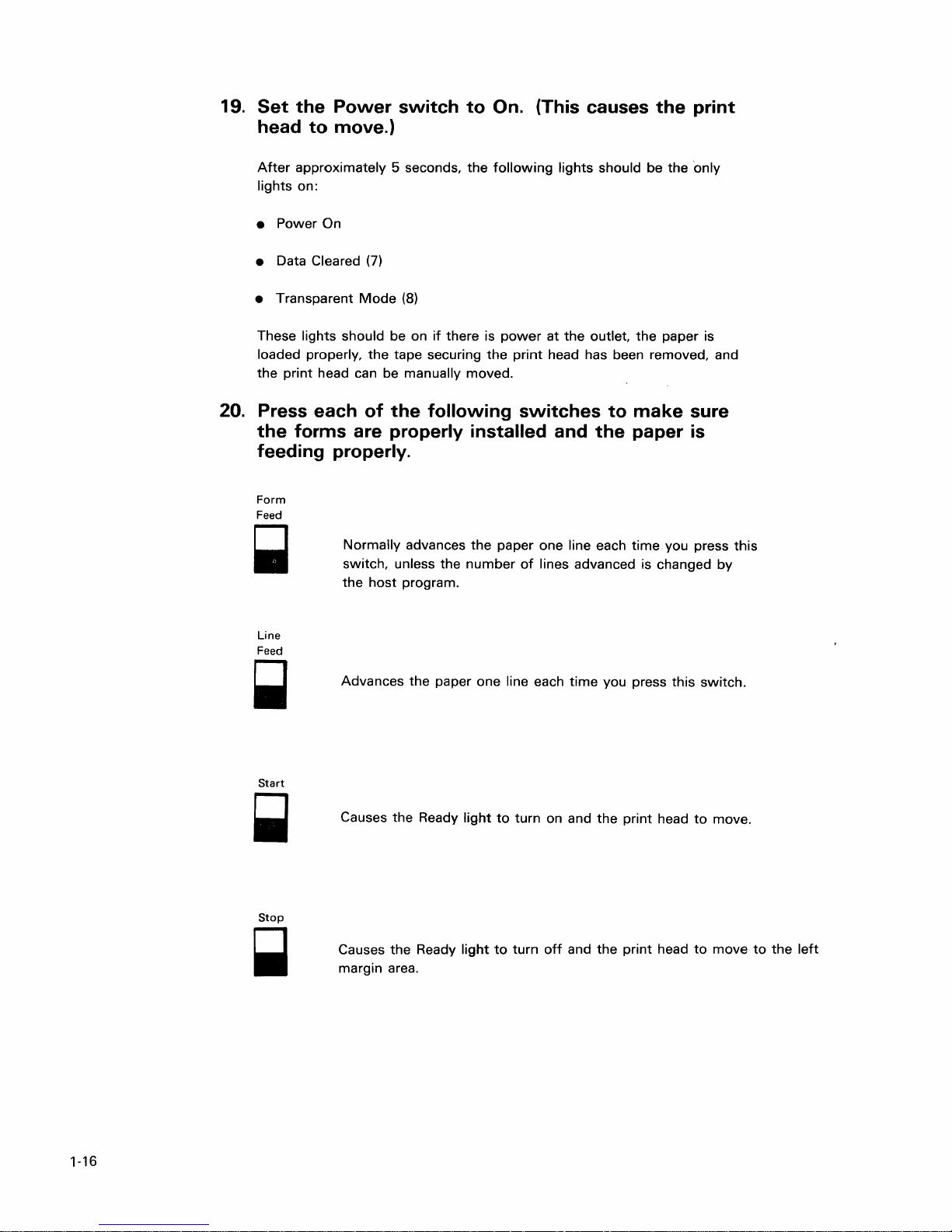
19.
Set
head
After
lights on:
• Power On
the
Power
to
move.)
approximately 5 seconds,
switch
to
On. (This causes
the
following
lights should be
the
the
print
only
Data Cleared
•
• Transparent
These lights should be on
loaded properly,
the
print
head can be manually moved.
20. Press each
the
forms are properly installed and
feeding properly.
Form
Feed
Normally
switch, unless the
the
Line
Feed
Advances
~
(7)
Mode
(8)
the
tape securing
of
the
host
program.
if
there is
the
following
advances
the
the
paper one line each time. you press
number
paper one line each
power
at
the
outlet,
print
head has been removed, and
switches
to
the
of
lines advanced is changed
time
you press this
the
paper is
make
paper
sure
is
this
by
switch.
Start
Stop
~
1-16
Causes
Causes
margin area.
the
the
Ready
Ready
light
light
to
turn on and
to
turn
off
and
the
the
print
print
head
head
to
to
move.
move
to
the
left
Page 19

TO PERFORM THE
PRINT
TEST
Do the
you have
Chapter 5. Problem Determination in
GA21-9260.
1.
2.
following
trouble
Set
and
4 5
a
a
a
a
Press
procedure
while
the
Status
Transparent
Storage a Internal
Check Check
Attention
Forms
Unit
Check
line
to
determine
doing this procedure, ask
switch
Mode
a
Feed.
if
you printer will
the
IBM
5256
to
Test.
[8]
lights
6 7
Graphic
Check
a Data
Line
Spacing
0:
print
correctly.
for
assistance
Printer Operator's Guide,
(The
go
off.)
Cleared
or
Data
8
Transparent
Mode
a
Status
Cancel
Test
ii
refer
Cleared
Normal
If
to
[7]
Power
.on
DOff
3. Press
off.)
Start.
Power
On
•
Stop
B
(The
a
~
light
Line
Feed
comes
Start
.~
Ready
line
Sync
2
a
Form
Feed
B
on,
then
System
Available
goes
Setting Up the Printer 1-17
Page 20

4.
Press
lines
8
(The Ready
Start
to
print.
again
to
The
start
press
light stays on.)
the
Stop
printing.
to
stop
Allow
the
printing.
about
The printout should look like
us
and Canada Printout
---------¢.«+I&---------!$*I;'-/--------:,I_>?---------'
(ABCDEFGHI--·~---IJKLMNOPQR-----\-STUVWXYZ------0123456789-----
---------¢.«+I&---------!$*I;'-/--------:,I_>?-------~-'
{ABCDEFGHI
---------¢.
{ABCDEFGHI------IJKLMNOPQR------\-STUVWXYZ------0123456789------
-----.----¢.
{ABCDEFGH
---------¢.
{ABCDEFGHI------IJKLMNOPQR------\-STUVWXYZ------0123456789------
---------¢.«+I&---------'$*>;'-/--------:,I_>?---------'
{ABCDEFGHI
---------¢. « + 1
(ABCDEFGH I -.-----
---------¢.
{ABCDEFGHI
------
I
JKLMNOPQR------\-STUVWXYZ-------0123456
« + 1
&---------
(
(+
1
&---.------!
I
------I JKLMNOPQR-'-----\ -STUVWXYZ
« + 1
&---------
------
I
JKLMNOPQR------\-STUVWXYZ--·-·---0123456
&-------
I
JKLMNOPQR---·--·· \ -STUVWXYZ·--·----O i 23456789·····
(
(+
1
&------.---!
------
I
JKLMNOPQR---·--·-\-STUVWXYZ-
-.-!
1
1
$*
$*
$*
$*
$*
I;
'-/-------.-:
I;
'-/--------:
I;
'-/--------.:
I
;'
-/.-
I, ' ./-
..
--.----:
......
- -...... :
,1_
,1_
---·---0
,1_
,1_
,1_
-.-
One
....
-.---
..
-----.--,
123456
......
-.--
...........
789·--··········
..
-.-'
789---·-·-·-
...
-.' :
789-··
.......
-,
-....... ,
>?->?>?-------
>?>?
.. -··0123456789-····
of
the following:
:~@'="-abcdefghi-------jklMnoP~r
:~@'="-abcdefghi
:
~@'
:
~@'
~@'
:O@'="-abcdefghi-
--.--
:
~@'
.... -..
~@'
Note: The printout character for this position could
- (hyphen).
Multinational Character Set Printout
datlaa:lj:iil
(ABCDEFGHI···(;
aaaaa
{AE<CDEFOHI ····00;,,, }
aaaaa:lj:fil
{ADCDEFGHI-8H66
;;aaaa~j:fi[
{ABCDEFGHI-8o&6
~i
a
{A£<CDtFGflI
aaaaii
{A£<CDEFGIII
;,aaaa~j:\l[
{A£<CDEf-OHI·
aciaaa
{ADCDEFGH 1
:lj:11 [ • (
aa
a
~Ij:"ii[
~.:.i\l
~~:li[
• (
("'"'
&eeee
I
.j
..
,.
i
0""
ii)
(+,
&eeee
• <
(I·
&eeee
}JKl..MNOF'QR~nh~QY\
•
«-I
&e&ee
}JKl.MNOrQR;::nh~Qj\
• (
(t
&ee€!e
···0066 }
• ( ( ..
t,e,!ee
(; H (,
6 ) ,Jl<LMNOF'QFL
• ( (
..
&fo€!ee I
,,"
I'
(,
) JKLMNOPQF(·::U U
• (
(·f
t,eeee
(;
Ii
<."
)
(11
JKI..MNOF'QfC:u U
I
.j
..
,.
i (1]
,JKl.MNOF'(~F(;::iiii
I
.j
..
,.
i
(!
Jt,~
I
.j
..
,
if!
1$*)
I
.j.
,.
i (l1$·X· )
,JKL.MNOPQR;~n
I
.j.
, i
(ll
j.
,.
i
(1
]
I
.j
..
,.
i
(1:1
JI\LMNOF'(~R:~nli
If the printout
$
~)
, A
••
/AAAAlliM:I~:
Ul'!)'\
STUVWXYZ
$~.
I, A ...
/
AAAAlliA~:N:
UIIY\
STUVWXYZ
) , A .
/;ViA
STUVWXYZI8066501234567893(juuu-
i A
..
/;ii.AAAlliM:i;;:
STUVWXYZ26066501234567893(jUuu-
,A
/
AAAAi!i"~:N
liuuy\
STUVWXYZ
$~.)
; A ···/;,AAI,IIiM:i;j:
Li
Ii
'II'IY\
STUVWXYZ
$~) , A····/AAAAlliA~:I'i:
'IUY\
STUVWXYZ
$~
) , A
••
/;ii.AA"IIi.\r·i;j: ,1.
U
UY\
STUVWXYZ
,I
...
>?!i!EE'EEt J:I
2600650123456789
,Yo
...
}?!i!EE'Eth
2600650123456789
A iii
M·
i;;
:
,1_
>?!i!EE'EEt
,1_
>?I/lEe:EEt i
: ,
Yo_
>':'!i!~:':E$:
2806650123456
,Yo
...
> ')!i!EE'EItt
2800600123456789
,;(_
}':>I/lEi£ELe:fi' i'
280b(~5012;3456789
..
}~'!i!~:E:EtE:t
2800660123456789
is
not legible:
Ii
tr
l:
li:
t'
It'
t'
It'
i' t ' :
789
it'
j:'
l:'
:
O@
'=
3(j(h)u-
:
O@
'=
3(jUUU··
:
~@'
:
~@'
O@
, =
:I(jUUU··
:
O(~
'=
:I(juuu·
:
O@
'=
1 (jihJU···
:
O@
'",
:I(juuu··
=
"····abcdefgh
=
"···abcdefgh
=
"···abcdefgh
="
···abcdefgh
--
="
abc.def9h
"li:Iabcdefgh
"li:Iabcdefgh
=
"li:Iabcdefgh
=
"li:Iabcdefgh
"li:Iabc
"li:Iabcdefgh
"li:Iabcdefgh
"0abcdefgh
de
f9h
..........
i··
...
I··
.......•.. - ..•.•. j k
I
.. -....•..•...•...
.....
i··· ........ j k
i
...
i
«»dil'±o
i ({»d::;l'±o j k
i
«»di.l'±o
i
«»dil':!:o
i
«»J
:::1'±
0 j k
i
«»dil'±o
i
«»dil'±
0 j k
i «»d:U':!.: ° j k
j k
lrlmop'ti"
j k
lMnop'F····
lllln()P'F
...
j k
llllnOp'tt
.................
j k
lMnOp'tl···
l'Il}"lOP'F··
j k l',\\"\(JP'tl··
be
a I (blob) instead
j k
lllInOP'Fi!Qa:.
lllInOP'Fi!Qa:.
j k
lrlmoP'F
i!Qa:. 1I1:11'-st
j k
lrlmoP'Fi!Qa:.,
lml10PV
i!Qa:_ I!
j k
lmnoP'F
i!Qa:_
I.mnopv
i!Qa:.
lrlmop'{\"
!!Qa:_
.r--
········-stuvwxyz
......
·······-·.st
llVWXYZ
...
stuvwxyZ
.
..............
-1
lIVWX·/Z······
········5 t llVWXYZ
.
··-·5t
uvwxyz···
.
···
..
tuvwxyz
- s'tuv,"",xyZ
111:11'-
st
uvwxyz
111:11'-
st
uvwXYZ
uvwxYZ
1It.l1'-
st
UVWXYZ i
1:1
I'
- s t IIVWX Y Z i LDt]1
111:1
I'···st
uvwxyz
111:11'··'> t uvwx
1I!:l1'-·st
uvwxyz
See
Note
....
..
.
..
of
a
i
':'Dtj·-¢£¥f\f§"'l---'
i
':'Dtj···¢£¥f\f§"'l·--··'
i
.:,Dtj·-¢t¥f\}§"'l·········,
.:,Iltj
··¢t¥f\f§"'l·-·-···'
.. ¢ £¥f,}§"'1···-·-'
i
LDt
]1···¢£¥f\f§"'l·-·····' 1 ,t
Y1 i
':'Dt
j···¢£¥f\f§"'l··-······,
i.:,llt
j···¢£¥f\f§"'l···
l,t··'
1 ,t
..
,
1 ,t
..
'
1 ,t
..
'
1 ,t
..
,
..
'
l,t
.,
...
-.,
l,t·
,
a. Press
b.
the
Adjust
num.ber
lower
number
c.
Repeat step 4.
Stop switch.
the
copy control dial. Turn
if
the
printing
if
the
is
printing is light.
Copy Control Dial
the
dial
smudging. Turn
to
the
the
<fIial
next
to
higher
the
next
1-18
Page 21

5.
Set
the
and Transparent
6.
Set
the Power switch
If
all the steps
proceed
to
Status switch
Mode
in
this procedure have been completed successfully,
Section
2.
to
Nonnal. (The Data Cleared
lights turn on.)
to
Off.
Setti
ng
Up the Pri nter 1-19
Page 22

1-20
Page 23

1.
Set
the
Power
Section
switch
2.
Connecting
to
Off.
the
Cable(s)
to
the
Printer
Before connecting
connected
System
If
the cable you are connecting
Display Station, a 5251 Display Station Model 1
make
The following illustration shows where the Terminator switch is located.
to
sure that the Terminator switch
the
cable
to
your printer, make sure the other end is
a system, a display station,
Dual
Display Station
to
your printer comes
on
or
another printer.
Printer
Cables
or
that machine
from
11,
or
a 5256 Printer,
is
set to 2.
Term i nator
a 5252 Dual
Sw
itch
Display Station
5252 Dual
Display
Station
5251
Display
Station Model
1
or
11
5256P~_
---------
---
Connecting the Cable(s)
to
the Printer
2-1
Page 24

The
cable
that
you
the
rear access panel on
either
illustration A
must
connect
the
or
illustration
back
B.
to
your
printer
of
the
printer. This panel
plugs
into a socket
resembles
on
Illustration
Socket--~--....;~
Cable
2.
If
plug
After
Checkout
Station
System/3S.
Display
System/3S,
manual
the
the
into
plugging
printer.
A
Rear
if
the
your
Access
cable
Model 2 or
If
Station
go
and
do
Panel
socket
in
the
cable,
printer
attaches
12, a
your
printer
Model 2 or
to
the
system
the
checkout
Illustration
Cable Sockets
resembles
as
shown
proceed
to
a 5251
System/34,
does
not
12, a
System/34,
setup
procedure
B
illustration
in
Figure
to
Printer
Display
or
a
attach
to
procedure
listed
A,
1.
a 5251
or
a
for
If
the
Rear
plug
into
directions
the
cable
following
a.
Line
up
slot in
connector
key
In
b. Push
the
cable socket;
retaining ring until
Access
the
lower
on
plugging
in,
proceed
page.
the
widest
the
cable
with
the
the
cable socket.
connector into
then
Panel
socket.
resembles
the
to
Setting
~'
See
cable
q=
the
turn
the
it
is
tight.
illustration
Figure 1
in.
After
the
Switches
Widest Slot
B,
for
plugging
on
the
Kevfl
,/
Retaining
Ring
Figure
1.
2-2
Connecting
Cable
to
Socket
Page 25

SETTING
THE
SWITCHES
There are
To
Set
1.
Contact
work
or
address,
two
types
the
Address
station
system
of
switches
4'
,
~~-~~--
to
set:
Q
.......
~~-
Switches:
the
person
address
operator).
which
responsible
Ask
will
be a number
Address
Address Switches
Terminator Switch
(for
example,
for
and
Terminator.
for
assigning
your
your
work
from 0 through
the
supervisor
station
6.
2.
Set
received.
Use
this table
of
the
three Address switches.
3.
If
Model 2 or
the
Checkout.
the
Address
to
determine
your
printer
Terminator
the
attaches
12, a
switch
switches
settings
to
System/34,
to 1 and
to
the
address
~
~
~
~
Invalid
a 5251
Display
or a System/3S,
proceed
you
0
1
2
3
4
5
6
7
to
have
Work
Station
Addresses
Station
set
Printer
If
your
Station
System/3S,
printer
Model 2 or
does
proceed
not
12, a
to
attach
System/34,
Cable
to
Thru
a 5251
Feature.
Display
or
a
Connecting the Cable(s)
to
the Printer 2-3
Page 26
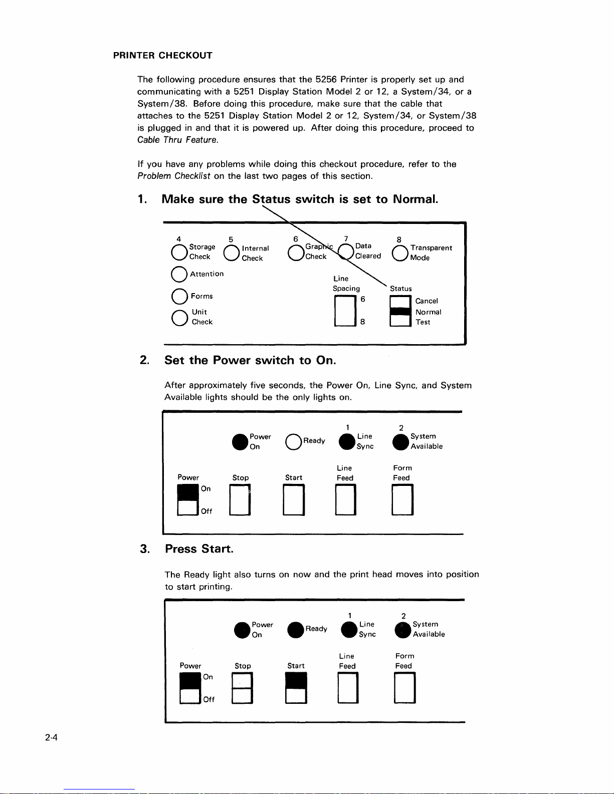
PRINTER
CHECKOUT
The
following
communicating
System/38.
attaches
is
plugged
Cable Thru Feature.
If
you have any
Problem Checklist on
1.
Make
procedure ensures
with
to
in and
Before
the
doing
5251 Display
that
problems
sure
that
a 5251 Display
this
procedure,
Station
it
is
powered
while
doing
the
last
two
pages
the
Status
the
5256
Station
up.
Model 2 or
make
Model 2 or
After
this
checkout
of
this
switch
Printer is
sure
that
12,
System
doing
this
procedure, refer
section.
is
set
properly
12, a
the
procedure, proceed
to
set
System/34,
cable
that
/34,
or
System
to
Normal.
up and
the
or
a
/38
to
4 5
Storage 0 Internal
Check Check
O
o
Attention
o Forms
Unit
Check
O
2.
Set
the
Power
After
approximately
Available lights should be
Power
.on
DOff
switch
five
Power
On
•
Stop
D
Line
Spacing
D:
to
On.
seconds,
the
the
only
lights
o Ready
Start
Power
on.
•
Line
Feed
D D
8
Transparent
Mode
O
Status
Cancel
Normal
Test
8
On, Line Sync, and
2
•
Form
Feed
System
Available
Line
Sync
D
System
3. Press Start.
The Ready
to
start
printing.
Power
~on
Off
2-4
light
also
turns
• Power
On
Stop
B
on
now
and
•
Ready
Start
~
the
print
head
moves
2
•
• Line
Sync
Line
Feed
System
Available
Form
Feed
D D
into
position
Page 27
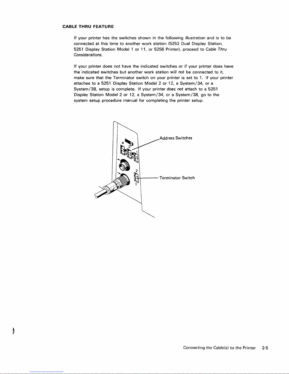
CABLE
THRU
If
your printer has the
connected at this
5251
Considerations.
If
your printer does
the indicated
make sure
attaches
System/38,
Display Station
system setup procedure
FEATURE
Display Station
that
to
switches
time
to
Model 1 or
not
have
switches
the
a 5251 Display Station
setup is complete.
Model 2 or
but
Terminator
manual
shown
another
the
another
switch
If
12, a
for
in
the
following
work
station (5252 Dual Display Station,
11,
or
5256 Printer), proceed
indicated switches
work
station will not be connected
on your printer is set
Model 2 or
your printer does not attach
System/34,
completing
12, a
or a
the
Address Switches
illustration and is
or
if
your printer does have
to
System/34,
System/38,
printer setup.
to
Cable Thru
1.
If
or
to
a 5251
go
to
to
be
to
it,
your printer
a
the
2
~
Terminator Switch
.Connecting the Cable(s)
to
the Printer 2-5
Page 28

Cable
Thru
Considerations
If
another
do
the
following:
1.
Connect
station
2.
Set
attaches
System/34,
your
Model 2 or
your
the
work
station is
into
the
printer
system
printer
to
be connected
the
cable
the
upper
Terminator
to
a 5251
or a System/3S,
does not
12, a
System/34,
setup
setup.
to
that
leads
cable
switch
to
Display
attach
to
procedure
the
printer you have
to
the
next
socket.
2.
If
your
Station
setup
a 5251
printer
Model 2 or
is
complete.
Display
or a System/3S,
manual
for
just
set up,
work
12, a
If
Station
go
to
completing
(l---+---
~Terminator
Upper Cable Socket
~,
Switch
2-6
Page 29
PROBLEM
If
the
1.
2.
CHECKLIST
conditions
Ensure
in Printer
that
System/34,
connected
•
Operating.
•
Trying
to
system
requires
•
Configured
Address
Cable
Thru
zero.)
Set
the
Power
recheck
properly
all
positioned
Checkout
the
5251
or
System/3S
is:
communicate
operator
might
printing.)
to
recognize
switches.
feature
switch
cable
connections
do
not
appear:
Display
to
with
have
the
(A
work
has a work
to
the
and
tightened.
Station
which
the
to
Model 2 or
your
printer.
run a program
setting
station
without
station
Off
position
to
make
printer
of
the
address
and
sure
(The
the
they
12,
is
that
of
are
3.
Make
sure
the
Status
switch
is
set
to
Normal.
Connecting
the
(continued
Cable(sl
to
the
on
next
Printer
page)
2-7
Page 30
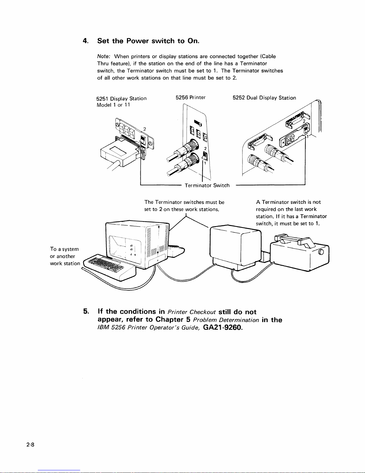
4.
Set
the
Note:
When
Thru feature),
switch,
of
all
other
5251 Display Station
Model 1
Power
the
Terminator
work
or
11
printers
if
the
stations
L--
switch
or
display
station on
switch
on
_____
to
stations
the
must
that
5256
On.
are
end
of
the
be
set
line
must
Printer
Terminator
connected
line has a
to
1. The
be
set
Switch
together
Terminator
Terminator
to
2.
5252
(Cable
switches
Dual Display Station
To
a system
or
another
work
station
5.
If
the
appear, refer
IBM
5256
The
Terminator
set
to
2 on these
conditions in
to
Chapter
Printer
Operator's
Printer
Guide,
switches must
work
stations.
Checkout
5
Problem
GA21-9260.
be
still do not
Determination
Terminator
A
required
station.
switch,
in
the
switch
on
the last
If
it
has a Terminator
it
must
be
work
set
is
to
not
1.
2-8
Page 31

~
n~_Ll~n
.;r
"'V'.II.'~''''
•
v.".,
Please use this
form
only
to
identify publication errors
or
request changes
to
publications. Technical questions
about I BM
systems, changes in I
BM
programming
support,
requests for additional publications,
etc,
should
be
directed
to
your I BM
representative or
to
the I BM
branch office nearest
your
location.
Error in publication (typographical, illustration,
and
so on). No reply.
Page
Number
Error
IBM
may
use
and
distribute
any
of
the
information
you
supply
in
any
way
it believes
appropriate
without
incurring
any
obligation whatever. You may,
of course,
continue
to
use
the
information
you
supply.
• No postage necessary if mailed in
the
U.S.A.
Inaccurate
or
misleading
information
in this publication. Please tell us
about
it by using this postage-paid form.
We
will
correct
or
clarify
the
publication,
or
tell
you
why a change
is
not
being
made,
provided
you
include
your
name
and
address.
Page
Number
Comment
Name
________________________________________
_
Address
CJ)CD
to
C
~
"0
01
""tIl\.)
....
01
o 0>
g
"tl
a.
:::!.
~
~
CD
~
G>
»
N
cO
N
to
o
I
N
Page 32

GA21-9290-2
Fold
and
tape
Please
do
not
staple
111111
Fold
and
NO POSTAGE
NECESSARY
IFMAILED
IN THE
UNITED
STATES
tape
to
»
0-
::J
C
::J
CD
BUSINESS
FIRST
CLASS PERMIT NO. 40
POSTAGE
IBM CORPORATION
General Systems Division
Development Laboratory
Publications, Dept. 245
Rochester, Minnesota 55901
Fold
and
tape
International Business Machines Corporation
General
4111 Northside Parkway
P.O. Box
Atlanta, Georgia 30301
(U.S.A. only)
Systems Division
2150
N.
W.
WILL
Please
REPLY
BE
PAID
do
not
BY
staple
MAIL
ARMONK,
ADDRESSEE:
N.
Y.
Fold
and
tape
General Business Group/International
44
South
Broadway
White Plains, New York
10601
U.S.A.
(I
nternational)
Page 33

Page 34

--...-
-_
------
-
----
-
~
--- ----
==-'='='=
International Business Machines Corporation
General Systems Division
4111 Northside Parkway
P.O. Box
Atlanta, Georgia 30301
(U.S.A.
General Business Group/International
44
South Broadway
White Plains, New York
U.S.A.
U nternational)
.....
---
2150
only)
-
-
<!>
N.W.
10601
:::!'!
CD
z
o
(f)
en
N
en
o
(f)
---
w
.j::>
(f)
---
w
ex>
6
9
GA21-9290-2
 Loading...