

Page 1

Front cover
IBM System p5 520 and 520Q
Technical Overview and Introduction
Finer system granulation using Micro-Partitioning
technology to help lower TCO
Support for versions of AIX 5L and
Linux operating systems
From Web servers to
integrated cluster solutions
Giuliano Anselmi
Charlie Cler
Carlo Costantini
Bernard Filhol
SahngShin Kim
Gregor Linzmeier
Ondrej Plachy
ibm.com/redbooks
Redpaper
Page 2

Page 3

International Technical Support Organization
IBM System p5 520 and 520Q
Technical Overview and Introduction
September 2006
Page 4

Note: Before using this information and the product it supports, read the information in “Notices” on
page vii.
Second Edition (September 2006)
This edition applies to IBM System p5 520 (product number 9131-52A), Linux, and IBM AIX
5L Version 5.3,
product number 5765-G03.
© Copyright International Business Machines Corporation 2006. All rights reserved.
Note to U.S. Government Users Restricted Rights -- Use, duplication or disclosure restricted by GSA ADP Schedule
Contract with IBM Corp.
Page 5

Contents
Notices . . . . . . . . . . . . . . . . . . . . . . . . . . . . . . . . . . . . . . . . . . . . . . . . . . . . . . . . . . . . . . . . .vii
Trademarks . . . . . . . . . . . . . . . . . . . . . . . . . . . . . . . . . . . . . . . . . . . . . . . . . . . . . . . . . . . . . viii
Preface . . . . . . . . . . . . . . . . . . . . . . . . . . . . . . . . . . . . . . . . . . . . . . . . . . . . . . . . . . . . . . . . . ix
The team that wrote this Redpaper . . . . . . . . . . . . . . . . . . . . . . . . . . . . . . . . . . . . . . . . . . . . ix
Become a published author . . . . . . . . . . . . . . . . . . . . . . . . . . . . . . . . . . . . . . . . . . . . . . . . . . .x
Comments welcome. . . . . . . . . . . . . . . . . . . . . . . . . . . . . . . . . . . . . . . . . . . . . . . . . . . . . . . . .x
Chapter 1. General description . . . . . . . . . . . . . . . . . . . . . . . . . . . . . . . . . . . . . . . . . . . . . 1
1.1 System specifications . . . . . . . . . . . . . . . . . . . . . . . . . . . . . . . . . . . . . . . . . . . . . . . . . . . 3
1.2 Physical package . . . . . . . . . . . . . . . . . . . . . . . . . . . . . . . . . . . . . . . . . . . . . . . . . . . . . . 3
1.2.1 Deskside model . . . . . . . . . . . . . . . . . . . . . . . . . . . . . . . . . . . . . . . . . . . . . . . . . . . 3
1.2.2 Rack-mount model . . . . . . . . . . . . . . . . . . . . . . . . . . . . . . . . . . . . . . . . . . . . . . . . . 5
1.3 Minimum and optional features. . . . . . . . . . . . . . . . . . . . . . . . . . . . . . . . . . . . . . . . . . . . 6
1.3.1 Processor features . . . . . . . . . . . . . . . . . . . . . . . . . . . . . . . . . . . . . . . . . . . . . . . . . 6
1.3.2 Memory features . . . . . . . . . . . . . . . . . . . . . . . . . . . . . . . . . . . . . . . . . . . . . . . . . . . 7
1.3.3 Disk and media features . . . . . . . . . . . . . . . . . . . . . . . . . . . . . . . . . . . . . . . . . . . . . 7
1.3.4 USB diskette drive . . . . . . . . . . . . . . . . . . . . . . . . . . . . . . . . . . . . . . . . . . . . . . . . . 8
1.3.5 I/O drawers . . . . . . . . . . . . . . . . . . . . . . . . . . . . . . . . . . . . . . . . . . . . . . . . . . . . . . . 8
1.3.6 Hardware Management Console models . . . . . . . . . . . . . . . . . . . . . . . . . . . . . . . 10
1.4 Express Product Offerings . . . . . . . . . . . . . . . . . . . . . . . . . . . . . . . . . . . . . . . . . . . . . . 11
1.4.1 Express Product Offerings requirements . . . . . . . . . . . . . . . . . . . . . . . . . . . . . . . 11
1.4.2 Configurator starting points for Express Product Offerings. . . . . . . . . . . . . . . . . . 11
1.5 System racks. . . . . . . . . . . . . . . . . . . . . . . . . . . . . . . . . . . . . . . . . . . . . . . . . . . . . . . . . 12
1.5.1 IBM 7014 Model T00 rack. . . . . . . . . . . . . . . . . . . . . . . . . . . . . . . . . . . . . . . . . . . 13
1.5.2 IBM 7014 Model T42 rack. . . . . . . . . . . . . . . . . . . . . . . . . . . . . . . . . . . . . . . . . . . 13
1.5.3 IBM 7014 Model S11 rack. . . . . . . . . . . . . . . . . . . . . . . . . . . . . . . . . . . . . . . . . . . 14
1.5.4 IBM 7014 Model S25 rack. . . . . . . . . . . . . . . . . . . . . . . . . . . . . . . . . . . . . . . . . . . 14
1.5.5 S11 rack and S25 rack considerations . . . . . . . . . . . . . . . . . . . . . . . . . . . . . . . . . 15
1.5.6 The ac power distribution unit and rack content . . . . . . . . . . . . . . . . . . . . . . . . . . 16
1.5.7 Rack-mounting rules . . . . . . . . . . . . . . . . . . . . . . . . . . . . . . . . . . . . . . . . . . . . . . . 18
1.5.8 Additional options for the rack. . . . . . . . . . . . . . . . . . . . . . . . . . . . . . . . . . . . . . . . 18
1.5.9 OEM rack . . . . . . . . . . . . . . . . . . . . . . . . . . . . . . . . . . . . . . . . . . . . . . . . . . . . . . . 21
Chapter 2. Architecture and technical overview . . . . . . . . . . . . . . . . . . . . . . . . . . . . . . 25
2.1 The POWER5+ processor. . . . . . . . . . . . . . . . . . . . . . . . . . . . . . . . . . . . . . . . . . . . . . . 26
2.2 Processor and cache . . . . . . . . . . . . . . . . . . . . . . . . . . . . . . . . . . . . . . . . . . . . . . . . . . 27
2.2.1 POWER5+ single-core module. . . . . . . . . . . . . . . . . . . . . . . . . . . . . . . . . . . . . . . 27
2.2.2 The p5-520 POWER5+ dual-core module . . . . . . . . . . . . . . . . . . . . . . . . . . . . . . 28
2.2.3 The p5-520Q quad-core module. . . . . . . . . . . . . . . . . . . . . . . . . . . . . . . . . . . . . . 29
2.2.4 Available processor speeds . . . . . . . . . . . . . . . . . . . . . . . . . . . . . . . . . . . . . . . . . 30
2.3 Memory subsystem . . . . . . . . . . . . . . . . . . . . . . . . . . . . . . . . . . . . . . . . . . . . . . . . . . . . 30
2.3.1 Memory placement rules. . . . . . . . . . . . . . . . . . . . . . . . . . . . . . . . . . . . . . . . . . . . 31
2.3.2 OEM memory . . . . . . . . . . . . . . . . . . . . . . . . . . . . . . . . . . . . . . . . . . . . . . . . . . . . 32
2.3.3 Memory throughput. . . . . . . . . . . . . . . . . . . . . . . . . . . . . . . . . . . . . . . . . . . . . . . . 32
2.4 I/O buses. . . . . . . . . . . . . . . . . . . . . . . . . . . . . . . . . . . . . . . . . . . . . . . . . . . . . . . . . . . . 33
2.5 Internal I/O subsystem . . . . . . . . . . . . . . . . . . . . . . . . . . . . . . . . . . . . . . . . . . . . . . . . . 34
2.6 64-bit and 32-bit adapters . . . . . . . . . . . . . . . . . . . . . . . . . . . . . . . . . . . . . . . . . . . . . . . 35
2.6.1 LAN adapters . . . . . . . . . . . . . . . . . . . . . . . . . . . . . . . . . . . . . . . . . . . . . . . . . . . . 35
© Copyright IBM Corp. 2006. All rights reserved. iii
Page 6

2.6.2 SCSI adapters. . . . . . . . . . . . . . . . . . . . . . . . . . . . . . . . . . . . . . . . . . . . . . . . . . . . 35
2.6.3 Integrated RAID options . . . . . . . . . . . . . . . . . . . . . . . . . . . . . . . . . . . . . . . . . . . . 36
2.6.4 iSCSI. . . . . . . . . . . . . . . . . . . . . . . . . . . . . . . . . . . . . . . . . . . . . . . . . . . . . . . . . . . 36
2.6.5 Fibre Channel adapter . . . . . . . . . . . . . . . . . . . . . . . . . . . . . . . . . . . . . . . . . . . . . 38
2.6.6 Graphic accelerators. . . . . . . . . . . . . . . . . . . . . . . . . . . . . . . . . . . . . . . . . . . . . . . 39
2.6.7 InfiniBand Host Channel adapter . . . . . . . . . . . . . . . . . . . . . . . . . . . . . . . . . . . . . 39
2.6.8 Asynchronous PCI-X adapters . . . . . . . . . . . . . . . . . . . . . . . . . . . . . . . . . . . . . . . 39
2.6.9 PCI-X Cryptographic Coprocessor . . . . . . . . . . . . . . . . . . . . . . . . . . . . . . . . . . . . 40
2.6.10 Additional support for PCI-X adapters you own . . . . . . . . . . . . . . . . . . . . . . . . . 40
2.6.11 Internal system ports. . . . . . . . . . . . . . . . . . . . . . . . . . . . . . . . . . . . . . . . . . . . . . 40
2.6.12 Ethernet ports . . . . . . . . . . . . . . . . . . . . . . . . . . . . . . . . . . . . . . . . . . . . . . . . . . . 41
2.7 Internal storage . . . . . . . . . . . . . . . . . . . . . . . . . . . . . . . . . . . . . . . . . . . . . . . . . . . . . . . 41
2.7.1 Internal media devices . . . . . . . . . . . . . . . . . . . . . . . . . . . . . . . . . . . . . . . . . . . . . 41
2.7.2 Internal hot-swappable SCSI disks. . . . . . . . . . . . . . . . . . . . . . . . . . . . . . . . . . . . 41
2.8 External I/O subsystem . . . . . . . . . . . . . . . . . . . . . . . . . . . . . . . . . . . . . . . . . . . . . . . . . 43
2.8.1 I/O drawers . . . . . . . . . . . . . . . . . . . . . . . . . . . . . . . . . . . . . . . . . . . . . . . . . . . . . . 43
2.8.2 7311 I/O drawer RIO-2 cabling . . . . . . . . . . . . . . . . . . . . . . . . . . . . . . . . . . . . . . . 44
2.8.3 7311 Model D20 I/O drawer SPCN cabling. . . . . . . . . . . . . . . . . . . . . . . . . . . . . . 45
2.9 External disk subsystems . . . . . . . . . . . . . . . . . . . . . . . . . . . . . . . . . . . . . . . . . . . . . . . 46
2.9.1 IBM TotalStorage EXP24 Expandable Storage . . . . . . . . . . . . . . . . . . . . . . . . . . 46
2.9.2 IBM System Storage N3000 and N5000. . . . . . . . . . . . . . . . . . . . . . . . . . . . . . . . 47
2.9.3 IBM TotalStorage DS4000 Series. . . . . . . . . . . . . . . . . . . . . . . . . . . . . . . . . . . . . 47
2.9.4 IBM TotalStorage DS6000 and DS8000 Series . . . . . . . . . . . . . . . . . . . . . . . . . . 47
2.10 Logical partitioning . . . . . . . . . . . . . . . . . . . . . . . . . . . . . . . . . . . . . . . . . . . . . . . . . . . 48
2.10.1 Dynamic logical partitioning . . . . . . . . . . . . . . . . . . . . . . . . . . . . . . . . . . . . . . . . 48
2.11 Virtualization . . . . . . . . . . . . . . . . . . . . . . . . . . . . . . . . . . . . . . . . . . . . . . . . . . . . . . . . 48
2.11.1 POWER Hypervisor . . . . . . . . . . . . . . . . . . . . . . . . . . . . . . . . . . . . . . . . . . . . . . 49
2.12 Advanced POWER Virtualization feature . . . . . . . . . . . . . . . . . . . . . . . . . . . . . . . . . . 51
2.12.1 Micro-Partitioning technology . . . . . . . . . . . . . . . . . . . . . . . . . . . . . . . . . . . . . . . 51
2.12.2 Logical, virtual, and physical processor mapping . . . . . . . . . . . . . . . . . . . . . . . . 52
2.12.3 Virtual I/O Server . . . . . . . . . . . . . . . . . . . . . . . . . . . . . . . . . . . . . . . . . . . . . . . . 54
2.12.4 Partition Load Manager. . . . . . . . . . . . . . . . . . . . . . . . . . . . . . . . . . . . . . . . . . . . 57
2.12.5 Integrated Virtualization Manager. . . . . . . . . . . . . . . . . . . . . . . . . . . . . . . . . . . . 57
2.13 Hardware Management Console . . . . . . . . . . . . . . . . . . . . . . . . . . . . . . . . . . . . . . . . 60
2.13.1 High availability using the HMC . . . . . . . . . . . . . . . . . . . . . . . . . . . . . . . . . . . . . 62
2.13.2 IBM System Planning Tool . . . . . . . . . . . . . . . . . . . . . . . . . . . . . . . . . . . . . . . . . 62
2.14 Operating system support. . . . . . . . . . . . . . . . . . . . . . . . . . . . . . . . . . . . . . . . . . . . . . 64
2.14.1 AIX 5L . . . . . . . . . . . . . . . . . . . . . . . . . . . . . . . . . . . . . . . . . . . . . . . . . . . . . . . . . 64
2.14.2 Linux . . . . . . . . . . . . . . . . . . . . . . . . . . . . . . . . . . . . . . . . . . . . . . . . . . . . . . . . . . 65
2.15 Service information . . . . . . . . . . . . . . . . . . . . . . . . . . . . . . . . . . . . . . . . . . . . . . . . . . . 66
2.15.1 Touch point colors. . . . . . . . . . . . . . . . . . . . . . . . . . . . . . . . . . . . . . . . . . . . . . . . 67
2.15.2 Securing a rack-mounted system into a rack . . . . . . . . . . . . . . . . . . . . . . . . . . . 67
2.15.3 Placing a rack-mounted system into a rack . . . . . . . . . . . . . . . . . . . . . . . . . . . . 67
2.15.4 Cable-management arm . . . . . . . . . . . . . . . . . . . . . . . . . . . . . . . . . . . . . . . . . . . 68
2.15.5 Operator control panel . . . . . . . . . . . . . . . . . . . . . . . . . . . . . . . . . . . . . . . . . . . . 69
2.15.6 System firmware . . . . . . . . . . . . . . . . . . . . . . . . . . . . . . . . . . . . . . . . . . . . . . . . . 70
2.15.7 Service processor . . . . . . . . . . . . . . . . . . . . . . . . . . . . . . . . . . . . . . . . . . . . . . . . 73
2.15.8 Hardware management user interfaces . . . . . . . . . . . . . . . . . . . . . . . . . . . . . . . 73
Chapter 3. RAS and manageability . . . . . . . . . . . . . . . . . . . . . . . . . . . . . . . . . . . . . . . . . 77
3.1 Reliability, availability, and serviceability. . . . . . . . . . . . . . . . . . . . . . . . . . . . . . . . . . . . 78
3.1.1 Fault avoidance. . . . . . . . . . . . . . . . . . . . . . . . . . . . . . . . . . . . . . . . . . . . . . . . . . . 78
3.1.2 First-failure data capture. . . . . . . . . . . . . . . . . . . . . . . . . . . . . . . . . . . . . . . . . . . . 78
iv IBM System p5 520 and 520Q Technical Overview and Introduction
Page 7

3.1.3 Permanent monitoring. . . . . . . . . . . . . . . . . . . . . . . . . . . . . . . . . . . . . . . . . . . . . . 79
3.1.4 Self-healing. . . . . . . . . . . . . . . . . . . . . . . . . . . . . . . . . . . . . . . . . . . . . . . . . . . . . . 80
3.1.5 N+1 redundancy . . . . . . . . . . . . . . . . . . . . . . . . . . . . . . . . . . . . . . . . . . . . . . . . . . 81
3.1.6 Fault masking . . . . . . . . . . . . . . . . . . . . . . . . . . . . . . . . . . . . . . . . . . . . . . . . . . . . 81
3.1.7 Resource deallocation . . . . . . . . . . . . . . . . . . . . . . . . . . . . . . . . . . . . . . . . . . . . . 81
3.1.8 Serviceability. . . . . . . . . . . . . . . . . . . . . . . . . . . . . . . . . . . . . . . . . . . . . . . . . . . . . 82
3.2 Manageability . . . . . . . . . . . . . . . . . . . . . . . . . . . . . . . . . . . . . . . . . . . . . . . . . . . . . . . . 8 3
3.2.1 Service processor . . . . . . . . . . . . . . . . . . . . . . . . . . . . . . . . . . . . . . . . . . . . . . . . . 83
3.2.2 Partition diagnostics . . . . . . . . . . . . . . . . . . . . . . . . . . . . . . . . . . . . . . . . . . . . . . . 84
3.2.3 Service Agent . . . . . . . . . . . . . . . . . . . . . . . . . . . . . . . . . . . . . . . . . . . . . . . . . . . . 85
3.2.4 IBM System p5 firmware maintenance . . . . . . . . . . . . . . . . . . . . . . . . . . . . . . . . . 87
3.3 Cluster solution . . . . . . . . . . . . . . . . . . . . . . . . . . . . . . . . . . . . . . . . . . . . . . . . . . . . . . . 88
Related publications . . . . . . . . . . . . . . . . . . . . . . . . . . . . . . . . . . . . . . . . . . . . . . . . . . . . . 91
IBM Redbooks . . . . . . . . . . . . . . . . . . . . . . . . . . . . . . . . . . . . . . . . . . . . . . . . . . . . . . . . . . . 91
Other publications . . . . . . . . . . . . . . . . . . . . . . . . . . . . . . . . . . . . . . . . . . . . . . . . . . . . . . . . 91
Online resources . . . . . . . . . . . . . . . . . . . . . . . . . . . . . . . . . . . . . . . . . . . . . . . . . . . . . . . . . 92
How to get IBM Redbooks . . . . . . . . . . . . . . . . . . . . . . . . . . . . . . . . . . . . . . . . . . . . . . . . . . 93
Help from IBM . . . . . . . . . . . . . . . . . . . . . . . . . . . . . . . . . . . . . . . . . . . . . . . . . . . . . . . . . . . 93
Contents v
Page 8

vi IBM System p5 520 and 520Q Technical Overview and Introduction
Page 9

Notices
This information was developed for products and services offered in t he U.S.A.
IBM may not offer the products, services, or features discussed in this document in other countries. Consult
your local IBM representativ e f or information on the products and services currently availab le in your area. Any
reference to an IBM product, program, or service is not intended to state or imply that only that IBM product,
program, or service may be used. Any functionally equivalent product, program, or service that does not
infringe any IBM intellectual property right may be used instead. However, it is the user's responsibility to
eval uate and verify the operation of an y non-IBM product, program, or service.
IBM may hav e p atents or pending patent applications cov ering subject matter described in this document. The
furnishing of this document does not give you any license to these patents. You can send license inquiries, in
writing, to:
IBM Director of Licensing, IBM Corporation, North Castle Drive Armonk, NY 10504-1785 U.S.A.
The following par agra ph does not apply to the United Kingdom or any other country where such provisions are
inconsistent with local law: INTERNATIONAL BUSINESS MACHINES CORPORATION PROVIDES THIS
PUBLICATION "AS IS" WITHOUT WARRANTY OF ANY KIND, EITHER EXPRESS OR IMPLIED,
INCLUDING, BUT NOT LIMITED TO, THE IMPLIED WARRANTIES OF NON-INFRINGEMENT,
MERCHANTABILITY OR FITNESS FOR A PARTICULAR PURPOSE. Some states do not allow disclaimer of
express or implied warranties in certain transactions, therefore, this stat ement may not apply to you.
This information could include technical inaccuracies or typo graphical erro rs. Change s ar e pe riodically made
to the information herein; these changes will be incorporated in new editions of the publication. IBM may mak e
improvements and /or changes in the product (s) and/or the prog ram(s) described in this pub lication at an y time
without notice.
Any references in this information to non-IBM Web sites are provided for convenience only and do not in any
manner serve as an endorsement of those Web sites. The materials at those Web sites are not part of the
materials for this IBM product and use of those Web sites is at your own risk.
IBM may use or distrib ute any of the inf ormation you supply in any wa y it b eliev es appro priate without incurring
any obligation to you.
Any performance data contained herein was determined in a controlled environment. Therefore, the results
obtained in other operating environments may vary significantly. Some measurements may have been made
on development-level systems and there is no guarantee that these measurements will be the same on
generally available systems. Furthermore, some measurement may have been estimated through
extrapolation. Actual results may vary. Users of this document should verify the applicable data for their
specific environment.
Information concerning non-IBM products was obtained from the suppliers of those products, their published
announcements or other publicly a vailab le sources . IBM has not tested t hose products and cannot confirm the
accuracy of performance, compatibility or any other claims related to non-IBM products. Questions on the
capabilities of non-IBM products should be addressed to the suppliers of those products.
This information contains examples of data and reports used in daily business operations. To illustrate them
as completely as possible, the examples include the names of individuals, companies, brands, and products.
All of these names are fictitious and any similarity to the names and addresses used by an actual business
enterprise is entirely coincidental.
COPYRIGHT LICENSE:
This information contains sample application programs in source language, which illustrates programming
techniques on various operating platforms. You may copy, modify, and distribute these sample programs in
any form without payment to IBM, for the purposes of developing, using, marketing or distributing application
programs conforming to the application prog ra mming interface for the oper ating pla tf orm f or which th e sample
programs are written. These examples have not been thoroughly tested under all conditions. IBM, therefore,
cannot guarantee or imply reliability, serviceability, or function of these programs. You may copy, modify, and
distribute these sample programs in any form without payment to IBM for the purposes of developing, using,
marketing, or distributing application programs conforming to IBM's application programming interfaces.
© Copyright IBM Corp. 2006. All rights reserved. vii
Page 10

Trademarks
The following terms are tradema rks of the In ternational Business Machines Corporation in the United States,
other countries, or both:
Eserver®
Redbooks (logo) ™
pSeries®
AIX 5L™
AIX®
Chipkill™
DS4000™
DS6000™
DS8000™
FICON®
The following terms are trademarks of other companies:
Internet Explorer, Microsoft, Windows, and the Windows logo are trademarks of Microsoft Corporation in the United
States, other countries, or both.
UNIX is a registered trademark of The Open Group in the United States and other countries.
Linux is a trademark of Liux Torvalds in the United States, other countries, or both.
Other company, product, or service names may be trademarks or servi ce marks of others.
HACMP™
IBM®
Micro-Partitioning™
OpenPower™
PowerPC®
POWER™
POWER Hypervisor™
POWER4™
POWER5™
POWER5+™
PTX®
Redbooks™
RS/6000®
Service Director™
System p™
System p5™
System Storage™
TotalStorage®
Virtualization Engine™
1350™
viii IBM System p5 520 and 520Q Technical Overview and Introduction
Page 11

Preface
This IBM Redpaper is a comprehensive gu ide that covers the IBM® System p5™ 520 and
520Q UNIX® servers. It introduces major hardware offerings and discusses their prominent
functions.
Professionals who wa nt to acquire a better understanding of IBM System p™ pro ducts should
read this document. The intended audience includes:
Clients
Marketing representatives
Technical support professionals
IBM Business Partners
Independent software vendors
This document expands the current set of IBM System p documentation and provides a
desktop reference that offers a detailed technical description of the p5-520 and the p5-520Q
system.
This publication does not replace the latest IBM System p mark e ting ma te rials and tools . It is
intended as an additional source of information that you can use, together with existing
sources, to enhance your knowledge of IBM server solutions.
The team that wrote this Redpaper
This Redpaper was produced by a te am of specialists from around the world working at the
International Technical Support Organization (ITSO), Austin Center.
Giuliano Anselmi is a certified pSeries® Presales T echnical Support Specialist who works in
the Field Technical Sales Support group based in Rome, Italy. For seven years, he was an
IBM Sserver pSeries Systems Product Engineer, supporting the Web Server Sales
Organization in EMEA, IBM Sales, IBM Busine ss Partners, Technical Support Organizations,
and IBM Dublin eServer Manufacturing. Giuliano has worked for IBM for 14 years, devoting
himself to RS/6000® and pSeries systems with his in-depth knowledge of the related
hardware and solutions.
Charlie Cler is a Certified IT Specialist for IBM and has o ver 21 years of e xperience with IBM.
He currently works in the United States as a presales Systems Architect representing IBM
Systems and Technology Group product offerings. He has been working with IBM System p
servers for over 16 years.
Carlo Costantini is a Certified IT Specialist for IBM and has over 28 years of e xperience with
IBM and IBM Business Partners. He currently works in Italy Presales Field Technical Sales
Support for IBM Sales Representative s and IBM Business Partners for all pSeries and IBM
System p5 systems offerings. He h as broad ma rket ing experience. He is a certified specialist
for pSeries and IBM System p servers.
Bernard Filhol is a UNIX Server Customer Satisfaction Resolution Team Leader for NEE
and SWE IOTs in Montpellier, France. He has more than 25 years of experience in
mainframes and five years of experience in pSeries Customer Satisfaction. He holds a
degree in Electronics from Montpellier University Institute of Technology. His areas of
© Copyright IBM Corp. 2006. All rights reserved. ix
Page 12

expertise include Mainframe Channel Subsystem, FICON®, and pSeries RAS. He has written
extensively on FICON.
SahngShin Kim is a sales specialist of STG infra-solution sales team in Seoul, Korea. For
three years, he was a sales specialist of IBM eServer pSeries, for two years of grid
computing, and for one year for infra-solutions. SahngShin has worked for IBM for six years,
devoting himself to RS/6000 and pSeries systems and STG server products and as an
architect for these products.
Gregor Linzmeier is an IBM Advisory IT Specialist for RS/6000 and pSeries workstation and
entry servers as part of the Systems and Technology Group in Mainz, Germany, supporting
IBM sales, IBM Business Partners, and clients with pre-sales consultation and
implementation of client/server environments. He has worked for more than 15 years as an
infrastructure specialist for RT, RS/6000, and AIX® in large CATIA client/server projects.
Ondrej Plachy is an IT specialist in IBM Czech Republic responsible for project design,
implementation, and support of large scale computer systems . He has 11 ye ars of e xperience
in the UNIX field. He holds the Ing. academic degree in Computer Science from Czech
Technical University (CVUT), Prague. He has worked at Supercomputing Centre of Czech
Technical University for four years and currently works for IBM (seven years) in the AIX 5L™
support team.
The project that produced this document was managed by:
Scott Vetter
IBM U.S.
Thanks to the following people for their contributions to this project:
Larry Amy , Baba Arimilli, Ron Arroy o, Joergen Berg, Terry Brennan, Erin Burke, Mark Dewalt,
Bob Foster, Ron Gonzalez, Dan Henderson, David A. Hepkin, Tenley Jackson, Hal Jenning s,
Carolyn Jones, Brian J King, Bill Mihaltse, Thoi Nguyen, Ken Rozendal, Craig Shempert,
Doug Szerdi, and Dave Willoughby
IBM
Become a published author
Join us for a two- to six-week residency program! Help write an IBM Redbook dealing with
specific products or solutions, while getting hands-on experience with leading-edge
technologies. You'll team with IBM technical professionals, Business Partners, or clients.
Your efforts will help increase product acceptance and client satisfaction. As a bonus, you'll
develop a network of contacts in IBM development labs, and increase your productivity and
marketability.
Find out more about the residency program, browse the residency index, and apply online at:
ibm.com/redbooks/residencies.html
Comments welcome
Your comments are important to us!
We want our papers to be as helpful as possible. Send us your comments about this
Redpaper or other Redbooks™ in one of the following ways:
x IBM System p5 520 and 520Q Technical Overview and Introduction
Page 13

Use the online Contact us review redbook form found at:
ibm.com/redbooks
Send your comments in an e-mail to:
redbook@us.ibm.com
Mail your comments to:
IBM Corporation, International Technical Support Organization
Dept. HYTD Mail Station P099
2455 South Road
Poughkeepsie, NY 12601-5400
Preface xi
Page 14

xii IBM System p5 520 and 520Q Technical Overview and Introduction
Page 15

Chapter 1. General description
The IBM System p5 520 and IBM System p5 520Q rack-mount and deskside servers
(9131-52A) give you new tools for managing on demand business, greater application
flexibility, and innovative technology in 1-core, 2-core, and 4-core configurations — all
designed to help you capitalize on the on demand business revolut ion. To simplify naming,
both products are referred to as
The p5-520 and p5-520Q have POWER5+™ processors which provide performance and
reliability advances (or enhancements) over the POWER5™ architecture that it replaces.
Chief among the enhancements is 90 nm processor fabrication technology.
p5-520 or p5-520Q.
1
The p5-520 processor is packaged as a 1-core single-core module running at 1.65 GHz with
no L3 cache or as a 1-core single-core module running at 2.1 GHz with 36 MB of L3 cache or
a 2-core dual-core module running at 1.65 or 1.9 or 2.1 GHz with 36 MB of L3. The p5-520Q
offers the same features but comes with a 4-core POWER5+ quad-core module running at
1.5 or 1.65 GHz with two 36 MB of L3 caches.
When you purchase a p5-520 or p5-520Q Express Product Offering that is only available on
an initial order request, you might qualify for processor activation at no extra charge. The
number of processors, total memory, quantity and size of disk, and the presence of a media
device are the only f eatures that determine if you are en titled to a processor entitlement at no
additional charge. Contact your marketing representative regarding the feature for Express
Product Offering or volume offering.
The p5-520 and p5-520Q server have a base of 1 GB of DDR2 memory that can be
expanded to 32 GB, designed for performance and exploitation of 64-bit addressing as used
in large database applications.
The p5-520 and p5-520Q include four front-accessible, hot-swap capable disk bays in a
minimum configuration with an additional four hot-swap capable disk bays as an optional
feature. The e ight disk bays can accommodate up to 2.4 TB of disk stor age u sing the 300 GB
Ultra320 SCSI disk drives. Other features included in the p5-520 and p5-520Q are six
hot-plug PCI-X slots with Enhanced Error Handling (EEH), integrated service processor,
integrated 10/100/1000 Mbps two-port Ethernet, two system, two USB, and two Hardware
Management Console (HMC) ports, integrated dual-channel Ultra320 SCSI controller,
hot-swappable power and cooling, and optional redundant power.
© Copyright IBM Corp. 2006. All rights reserved. 1
Page 16

Three non-hot-swappable media bays ar e used to accommodate additional devices . Two
media bays only accept slim-line media de vices, such as DVD-ROM or DVD-RAM drives, and
one half-height bay is used for a tape drive. The rack-mount model also has I/O extension
capability using the RIO-2 bus that allows attachment of the 7311 Model D20 I/O drawers.
For partitioning, we recommend an HMC. Dynamic LPAR is supported on the p5-520 and
p5-520Q servers, allowing up to two logical partitions. In addition, the optional Advanced
POWER™ Virtualization feature supports up to 40 micro-partitions using Micro-Partitioning™
technology. The Integrated Virtualization Manager provides partition management in settings
where an HMC is unavailable or not desired.
Additional reliability and availability features include redundant hot-swappable cooling fans
and redundant power supp lies. Along with these components, the p5-520 and p5-520Q are
designed to provide an extensive set of reliability, availability, and serviceability (RAS)
features that include a dual service processor, fault isolation, recovery from errors without
stopping the system, avoidance of recurring failures, and predictive failure analysis.
The p5-520 and p5-520Q are backed by a three-year limited warranty. Check with your IBM
representative for particular warranty availability in your region.
2 IBM System p5 520 and 520Q Technical Overview and Introduction
Page 17
1.1 System specifications
Table 1 -1 lists the general system specifications of the p5-520 and p5-520Q systems.
Table 1-1 IBM System p5 520 and IBM System p5 520Q specifications
Description Range
Operating temperature 5 to 35 degrees Celsius (41 to 95 F)
Relative humidity 8% to 80%
Operating voltage 100 to 127 or 200 to 240 V ac (auto-ranging)
Operating frequency 47/63 Hz
Maximum power consumption 750 watts maximum
Maximum thermal output 2560 BTU/hour (maximum)
1.2 Physical package
This section discusses the major physical attrib utes of the p5-520 and p5-520Q systems in
rack-mounted and deskside versions that are selectable through a feature code.
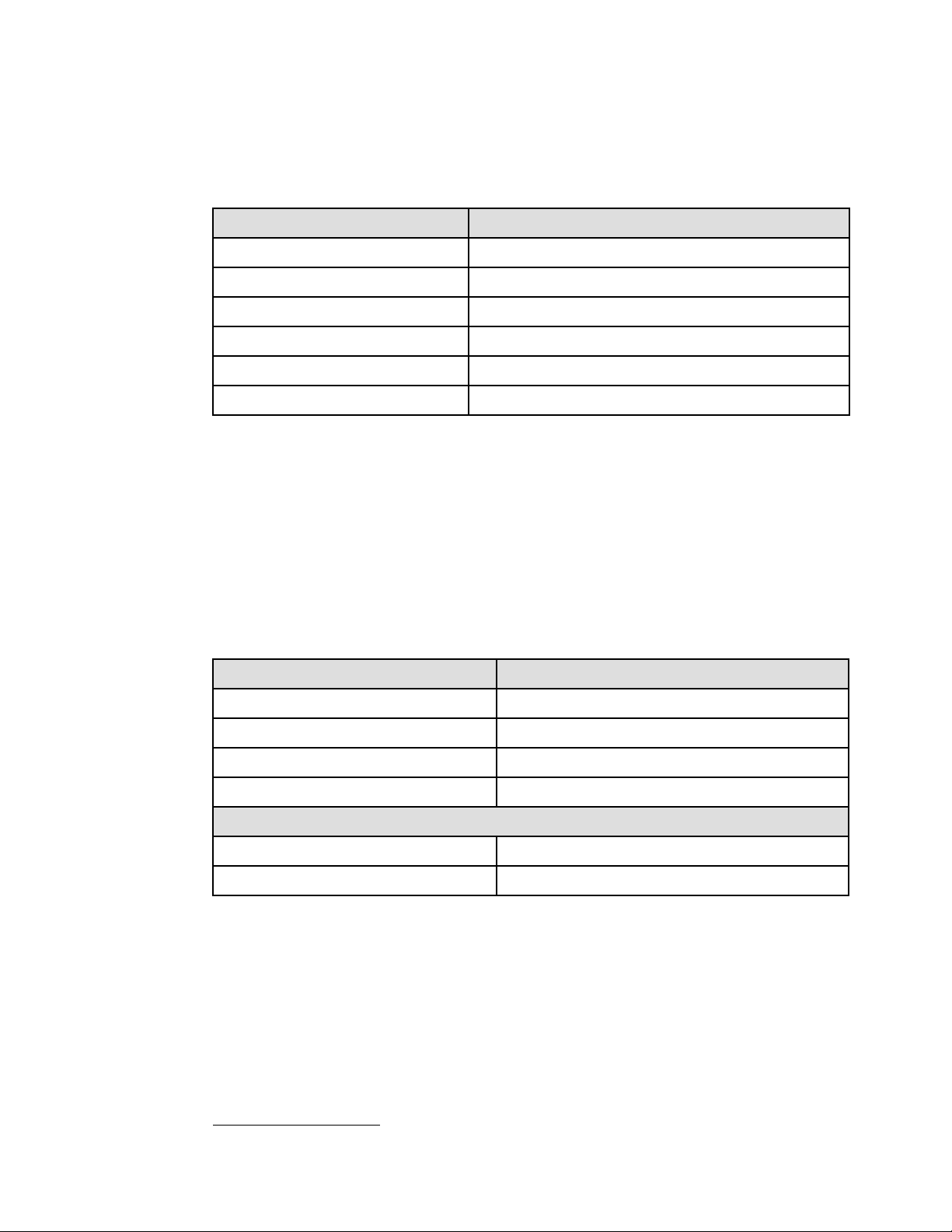
1.2.1 Deskside model
The p5-520 and p5-520Q can be configured as deskside models. Table 1-2 lists the physical
attributes
Table 1-2 Physical attributes of the deskside model
Dimension
Height 533 mm (21.0 in.)
Width 201 mm (7.9 in.)
Depth (without rear cover; FC 6587) 630.0 mm (23.0 in.)
Depth (with rear cover; FC 6587) 706.0 mm (27.8 in.)
Weight
Weight 43 kg (95 lb.)
Shipping weight 50 kg (110 lb.)
1
and Figure 1-1 on page 4 shows the system.
a
a. For a specific region, such as China, check specifications for specific dimensions.
Deskside (FC 7919)
1
One Electronic Industries Association Unit (1U) is 44.45 mm (1.75 in.).
Chapter 1. General description 3
Page 18
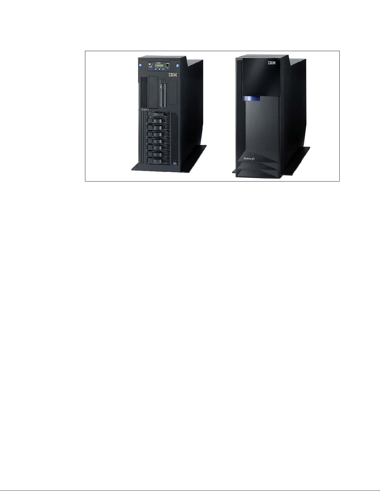
Figure 1-1 The deskside model (FC 7184) and acoustic cover (right FC 7185)
The p5-520 or p5-520Q, when configur ed as a deskside se rver, is ideal for e n vironm ents tha t
require local access to the machine, such as applications that require a native graphics
display. T o order a system as a de skside vers ion, FC 7184 or FC 7185 is required. FC 7185 is
designed for quiet operation in office environments. The system is designed to be set up by
the client and, in most cases, does not require the use of any tools. The system includes full
setup instructions.
The GXT135P 2D graphics accelerator with analog and digital interfaces (FC 1980) is
availab le and is supported fo r SMS , firmware menus , and othe r low-level functions, as w ell as
when AIX 5L or Linux® starts the X11-based graphical user interface. You can use graphical
AIX 5L system tools for configuration management if the adapter is connected to the primary
console, such as the IBM 15-inch, 17-inch, 19-inch, or 20-inch TFT Color Monitor (FC 3641,
FC 3645, FC 3644, and FC 3643).
4 IBM System p5 520 and 520Q Technical Overview and Introduction
Page 19
1.2.2 Rack-mount model
The IBM System p5 520 or IBM System p5 520Q can be configured as a 4U rack-mount
model with the selected feature code. Table 1-3 lists the physical attributes and Figure 1-2
shows the system.
Table 1-3 Physical attributes of the rack-mount model
Dimension
Height 178 mm (7.0 in.)
Width 437 mm (17.2 in.)
Depth 584 mm (23.0 in.)
Weight
Weight 43.0 kg (95 lb.)
Shipping weight 53.0 kg (117 lb.)
a. For a specific region, such as China, check specifications for specific dimensions.
a
Rack (FC 7918)
Figure 1-2 IBM System p5 520 and IBM System p5 520Q rack-type model (FC 7160)
The p5-520 or p5-520Q, when configured as a 4U rack-mounted server, is intended to be
installed in a 19-inch rack, thereby enabling efficient use of computer room floor space. If the
IBM 7014 T42 rack is used to mount the server, it is possible to place up to 10 systems in an
area of 644 mm (25.5 in.) x 1147 mm (45.2 in.).
To order a p5-520 or p5-520Q system as a rack-mounted version, FC 7190 must be selected.
In addition to the rack-mount ed version, the server can be installed in either IBM or OEM
racks. Therefore, y ou are required to select one of the following features:
IBM Rack-mount Drawer Rail Kit (FC 7160)
OEM Rack-mount Drawer Rail Kit (FC 7161)
Included with the rack-mounted server packaging are all of the components and instructions
necessary to enable installation in a 19-in ch rack using suitable tools.
The GXT135P 2D graphics accelerator with analog and digital interfaces (FC 1980) is
availab le and is supported fo r SMS , firmware menus , and othe r low-level functions, as w ell as
when AIX 5L or Linux starts the X11-based graphical user interface. You can use graphical
Chapter 1. General description 5
Page 20

AIX 5L system tools for configura tion management if the adapter is connected to a common
maintenance console, such as the 7316-TF3 rack-mounted flat-panel display.
1.3 Minimum and optional features
The systems are based on a flexible, modular design based on POWER5+ processors. The
server is available in 1-core, 2-core, and 4-core configurations that feature the following:
1.65 (SCM and DCM), 1.9 or 2.1 GHz (DCM), and 1.5 or 1.65 GHz (QCM) POWER5+
processors.
From 1 GB to 32 GB of total system memory capacity using 533 MHz DDR2 DIMM
technology.
Four SCSI disk drives in a minimum configuration, eight SCSI disk drives with an optional
second 4-pack enclosure for a total internal storage capacity of 2.4 TB using 300 GB disk
drives.
Six PCI-X slots (one 266 MHz 64-bit PCIX-2, three 133 MHz 64-bit PCI-X, two 66 MHz
32-bit PCI-X). All slots support Enhanced Error Handling (EEH).
Two slim-line media bays for optional storage devices.
One half-high bay for an optional tape device.
The p5-520 and p5-520Q, including the service processor that is described in 3.2.1, “Service
processor” on page 83, support the following native ports:
Two 10/100/1000 Ethernet ports on a single controller
Two system ports
Two USB 2.0 ports on a single controller
Optionally, an external USB diskette drive 1.44 (FC 2591) is available.
Two HMC ports
Optional GX+ Bus to RIO-2 adapter card (FC 2888)
Two SPCN ports
In addition, the p5-520 and p5-520Q feature one internal Ultra320 SCSI dual channel
controller, redundant hot-swap power supply (optional), and cooling fans.
The system supports 32-bit and 64-bit applications and requires specific lev els of AIX 5L and
Linux operating systems. For more information, see 2.14, “Operating system support” on
page 64.
1.3.1 Processor features
The p5-520 featu res one or two PO WER5 + processors , each with one or two cores running at
1.65 GHz, 1.9 GHz, or 2.1 GHz, or the p5-520Q with four cores running at 1.5 GHz or
1.65 GHz. The processors are installed on either single-core modules (SCM), dual-core
modules (DCM), or quad-core modules (QCM). The POWER5+ processor modules are
mounted directly to the system planar. Table 1-4 on page 7 lists the available processor
features.
6 IBM System p5 520 and 520Q Technical Overview and Introduction
Page 21
Table 1-4 Processor feature codes
Feature code Description
8321 1-core 1.65 GHz POWER5+ Processor Card, no L3 Cache
8323 2-core 1.65 GHz POWER5+ Processor Card, 36 MB L3 Cache
8330 2-core 1.9 GHz POWER5+ Processor Card, 36 MB L3 Cache
8315 1-core 2.1 GHz POWER5+ Processor Card, 36 MB L3 Cache
8316 2-core 2.1 GHz POWER5+ Processor Card, 36 MB L3 Cache
8333 4-core 1.5 GHz POWER5+ Processor Card, 2 x 36 MB L3 Cache
8314 4-core 1.65 GHz POWER5+ Processor Card, 2 x 36 MB L3 Cache
Note: When configuring p5-520 and p5 - 520Q s yste m s, remember that th e pr ocessor
modules are mounted directly on the system planar and cannot be upgraded.
1.3.2 Memory features
The minimum memory requirement for t he p5-520 and p5-520Q servers is 1 GB, and the
maximum capacity is 32 GB using 533 MHz DDR2 technology. The planar of each system
has eight sockets for memory DIMMs. Table 1-5 lists the available memory features.
Table 1-5 Memory feature codes
Feature code Description
1930 1 GB (2 x 512 MB) DIMMs, 276-pin DDR2, 533 MHz SDRAM
1931 2 GB (2 x 1 GB) DIMMs, 276-pin DDR2, 533 MHz SDRAM
1932 4 GB (2 x 2 GB) DIMMs, 276-pin DDR2, 533 MHz SDRAM
1934 8 GB (2 x 4 GB) DIMMs, 276-pin DDR2, 533 MHz SDRAM
Note that an amount of memory is always in use by the Hypervisor , e v en when the machine is
not partitioned. You can use the System Planning Tool to calculate the amount of available
memory for an operating system based on machine configuration as follows:
http://www.ibm.com/servers/eserver/iseries/lpar/systemdesign.html
1.3.3 Disk and media features
The minimum configuration includes a 4-pack disk drive enclosure. A second 4-pack disk
drive enclosure can be installed by ordering FC 6574 or FC 65 94, s o that th e ma ximum
internal storage capacity can reach 2.4 TB (using the disk drive features availabl e at t he time
of writing). The p5-520 and p5-520Q feature up to eight disk drive bays, two slim-line media
device ba ys , an d one half-h eight media bay. The minimum configuration req uires at least o ne
disk drive. Table 1-6 shows the disk drive feature codes that each bay can contain.
Chapter 1. General description 7
Page 22

Table 1-6 Hot-swappable disk drive options
Feature code Description
1968 73.4 GB ULTRA320 10 K rpm SCSI hot-swappable disk drive
1969 146.8 GB ULTRA320 10 K rpm SCSI hot-swappable disk drive
1970 36.4 GB ULTRA320 15 K rpm SCSI hot-swappable disk drive
1971 73.4 GB ULTRA320 15 K rpm SCSI hot-swappable disk drive
1972 146.8 GB ULTRA320 15 K rpm SCSI hot-swappable disk drive
1973 300 GB ULTRA320 10 K rpm SCSI hot-swappable disk drive
You can install any combination of the following DVD-ROM and DVD-RAM drives in the two
slim-line bays:
DVD-RAM drive, FC 1993
DVD-ROM drive, FC 1994
A logical partition running a suppor t ed rele a se of Linux requir es a DVD-ROM drive or
DVD-RAM drive to provide a way to run the diagnostics CD for hardware diagnostics.
Concurrent diagnostics, as provided by the AIX 5L diag command, are not available on the
Linux operating system at the time of writing.
You can install supplementary devices in the half-height media bay, such as:
Internal 4 mm 36/72 GB LVD tape drive, FC 1991
IBM 80/160 GB internal tape drive VXA, FC 1992
IBM 160/320 GB internal tape drive with VXA-3 technology, FC 1892
IBM 200/400 GB LTO2 tape drive, FC 1997
DVD devices installed in the slim-line bays must be assigned as a group to a single LPAR on
a partitioned system.
A dual-channel RAID enablement daughter card is also available (FC 1907) .
1.3.4 USB diskette drive
The externally attached USB diskette drive provides storage capacity up to 1.44 MB
(FC 2591) on high-density (2HD) floppy disks and 720 KB on a double density floppy disk. It
includes a 350 mm (13.7 in.) cable with standard USB connector. This super slim-line and
lightweight USB V2-attached diskette drive takes its power requirements from the USB port.
The drive can be attached to the integrated USB ports or to a USB adapter (FC 2738). A
maximum of one USB disket te driv e is supported per integr ated cont roller/adapt er. The same
controller can share a USB mouse and keyboard.
1.3.5 I/O drawers
The p5-520 and p5-520Q have six internal PCI-X slots — three long slots and three short
slots. If you need more PCI-X slots to extend the number of LPARs and partitions, you can
connect up to four 7311 Model D20 drawers to the optional RIO-2 ports (FC 2888) that are
provided on the rear of the system in a minimum configuration.
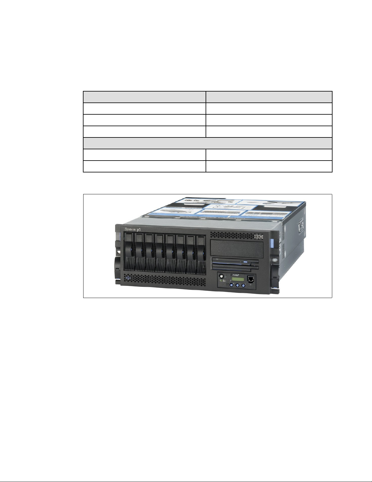
The 7311 Model D20 I/O drawe r is a 4U full-size drawer, which must be mounted in a rack. It
features seven hot-pluggable PCI-X slots and, optionally, up to 12 hot-swappable disks
arranged in two 6-packs. Redundant, concurrently maintainable power and cooling is an
optional feature (FC 6268). The 7311 Model D20 I/O drawer offers a modular growth path for
a system with increasing I/O requirements . When a p5-520 or p5-520Q is fully conf igured with
8 IBM System p5 520 and 520Q Technical Overview and Introduction
Page 23
four attached 7311 Model D20 drawers, the combined system supports up to 34 PCI-X
adapters (in a maximum configuration, remot e I/O expansion cards are required) and
56 hot-swappable SCSI disks, for a total internal capacity of 16.8 TB using 300 GB disks.
PCI-X and PCI cards are inserted from the top of the I/O drawer down into the slot from the
drawer’s front service position. The installed adapters are protected by plastic separators,
which are designed to prevent grounding and damage when adding or removing adapters.
The drawer has the following attributes:
4U rack-mount enclosure assembly
Seven PCI-X slots 3.3 volt, keyed, 133 MHz hot-pluggable
Two 6-pack hot-swappable SCSI bays (optional)
Redundant hot-swap power (optional)
Two RIO-2 ports and two SPCN ports
Note: A 7311 Model D20 I/O drawer initia l order or a n e xisting 73 11 Model D20 I /O drawer
that is migrated from another pSeries system must have the RIO-2 ports available
(FC 6417).
The I/O drawer has the following physical characteristics:
Width: 482 mm (19.0 in.)
Depth: 610 mm (24.0 in.)
Height: 178 mm (7.0 in.)
Weight: 45.9 kg (101 lb.)
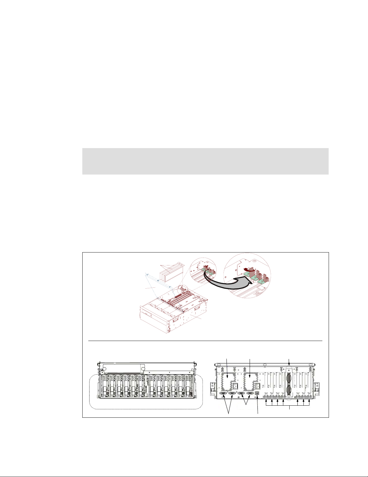
Figure 1-3 shows the different views of the 7311-D20 I/O drawer.
Adapters
Service
Access
I/O
Drawer
Front Rear
Operator panel
8 9 A B C D 8 9 A B C D
SCSI disk locations and IDs
Figure 1-3 7311-D20 I/O drawer views
Power supply 2
Reserved ports
Power supply 1
SPCN ports
Rack indicator
RIO ports
1 2 3 4 5 6 7
PCI-X slots
Chapter 1. General description 9
Page 24
Note: The 7311 Model D20 I/O drawer is designed to be installed by an IBM service
representative . O nly the 731 1 Mode l D20 I /O dr awer is supported on a p5-520 or p5-520Q
system.
1.3.6 Hardware Management Console models
A p5-520 or p5-520Q can be either HMC-mana ged or non-HMC-ma naged. In HMC-ma naged
mode, an HMC is required as a dedicated workstation that allows you to configure and
manage partitions. The HMC provides a set of functions to manage the system LPARs,
dynamic LPAR operations, virtual features, Capacity on Demand, inventory and microcode
management, and remote pow er cont rol functio ns. These functions also include the handling
of the partition profiles that define the processor, memory, and I/O resources allocated to an
individual partition. For detailed information about the HMC, see 2.13, “Hardware
Management Console” on page 60.
Note: Non-HMC-managed modes are full system partition modes, where only o ne partition
contains all system resources that exist on the system. For more information about using
the Integrated Virtualization Manager (IVM), see 2.12.5, “Integrated Virtualization
Manager” on page 57.
Table 1-7 lists the HMC options for POWER5 processor-based systems that are available at
the time of writing. You can also use existing HMC models.
Table 1-7 Supported HMC models
Type-model Description
7310-C05 IBM 7310 Model C05 Deskside Hardware Management Console
7310-CR3 IBM 7310 Model CR3 Rack-Mount Hardware Management Console
Systems require Ethernet connectivity between HMC and one of the Ethernet ports of the
service processor. Ensure that sufficient HMC Ethernet ports are available to enable public
and private networks if you need both. The 7310 Model C05 is a deskside model with one
native 10/100/1000 Ethernet port. It can be extended with two additional two-port
10/100/1000 Gb adapters. The 7310 Mod el CR3 is a 1U, 19-inch rack mou nt able drawer that
has two native Eth ernet ports and can be e x te nd ed wit h one ad dit ion al t w o- po rt 10/100/1000
Gb adapter.
In HMC-managed installations with very high demand for high availability, you should
consider deployment of tw o HMCs. The service processor allows for conne ction of two HMCs ,
and there is no need for special handli ng of a dual HMC environment. HM Cs provide a loc king
mechanism so that only one HMC has write access to the service processor at a time.
When an HMC is connected to the system, the integrated system ports are disabled.
To support a non-Ethernet HACMP™ heartbeat, you need to provide an asynchronous
adapter (FC 5723 or FC 2943).
Note: It is not possible to connect POWER4™ with POWER5 or POWER5+
processor-based systems simultaneously to the same HMC. However, it is possible to
connect POWER5 and POWER5+ processor-based systems together to the same HMC.
10 IBM System p5 520 and 520Q Technical Overview and Introduction
Page 25

1.4 Express Product Offerings
The Express Product Offerings provide a convenient way to order any of several
configurations that are designed to meet typical client requirements. Special reduced pricing
is available when a system order satisfies specific configuration requirements for memory,
disk drives, and processors.
1.4.1 Express Product Offerings requirements
When you order an Express Product Offering, the configurator offers a choice of starting
points onto which you can add. You can configure systems with one or two processor cards
and two or four proce ssor activations.
With the purchase of an Express Product Offering, f or each paid processor activ ation, you are
entitled to one processor activation at no additional charge, if the following requirements are
met:
The system must have at least two disk drives of at least 73.4 GB each.
There must be at least 2 GB of memory installed for each active processor.
If you order a p5-520 server Express Product O ff ering as defined here , y ou might qu alify f or a
processor activation at no extra charge. The number of processors, total memory, quantity
and size of disk, and presence of a media device are the only features that determine if a
client is entitled to a processor entitlement at no additional charge.
When you purchase an Express Product Offering, you are entitled to a lo wer priced AIX 5L or
Linux operating system license, or you can choose to purchase the system with no operating
system. The lower priced AIX 5L or Linux oper ating system is proces sed via a f eature number
on AIX 5L and either Red Hat or SUSE Linux. You can choose either the lower priced AIX 5L
or Linux subscription, but not both.
If you choose AIX 5L for your lo wer priced operating system, y ou can also order Linux b ut will
purchase your Linux subscription at full price versus the reduced price. The same is true if
you choose a Linux subscription as your lower priced operating system. Systems with a
reduced price AIX 5L offering are the IBM System p5 Express Product Offering, AIX 5L
edition. Systems with a lower priced Linux operating system are referred to as the
IBM System p5 Express Product Offering, OpenPower™ edition. In the case of Linux, only
the first subscription purchased is lower priced. So, for exa mple, additional licenses
purchased for Red Hat to run in multiple partitions will be at full price.
You can make changes to the standard features as needed and still qualify for processor
entitlements at no additional charge and a reduced price AIX 5L or Linux operating system
license.
If the system was initially ordered as an Express Product Offering, the system can be
expanded at a later time using Express Product Offering pricing, when additional processors
and activations along wit h the required memory are ordered on the same hardware upgrade
order. The upgraded p5-520Q configuration must satisfy the Express Product Offering
requirements for disk drives, memory, and processors. However, if the selection of total
memory or disk drives is smaller than the total defined as the minimums, it disqualifies the
order as an Express Product Offering.
1.4.2 Configurator starting points for Express Product Offerings
All Express Product Offerings have a set of standard features for the rack-mounted or
deskside versions as listed in Table 1-8 on page 12.
Chapter 1. General description 11
Page 26
Table 1-8 Express Product Offering standard set of feature codes
Feature code description Rack-mounted feature
codes
System bezel and hardware 7190 7916 x 1
Rack-mount rail kit 7160 x 1 n/a
850 Watt power supply 5159 x 1 5159x 1
IDE DVD-ROM 1994 x 1 1994 x 1
Media backplane 7877 x 1 7877 x 1
4-pack disk drive enclosure 6574 x 1 6574 x 1
73.4 GB 10 k disk drives 1968 x 2 1968 x 2
Deskside feature code
A specific Express Product Offering ID or specific offering feature code is used to select the
processor type and quantity, and the associated memory feature code and quantity, on top of
the standard set. Table 1-9 and Table 1-10 provide these configuration differences.
Table 1-9 Express Product Offering features - SCM and DCM configurations
Description 1.65 GHz 1.9 GHz 2.1 GHz
Configuration 1-core 2-core 2-core 1-core 2-core
Processor cards 8321 x 1 8323 x 1 8330 x 1 8315 x 1 8316 x 1
Processor activations n/a 7309 x 1 7320 x 1 n/a 7271 x 1
Zero-priced express
activations
Total active processors12112
Minimum memory 1 GB 2 GB 2 GB 1 GB 2 GB
Table 1-10 Express Product Offering features - QCM configurations
Description 1.5 GHz 1.65 GHz
Configuration 4-core 4-core
Processor cards 8333 x 1 8314
Processor activations 7337 x 2 7269
Zero-priced express activations 8421 x 2 8479
Total active processors 4 4
Minimum memory 4 GB 4 GB
1.5 System racks
8418 x 1 8419 x 1 8410 x 1 8480 x 1 8481 x 1
The IBM 7014 Model S11, S25, T00, and T42 Racks are 19-inch racks for general use with
IBM System p and OpenPower Edition rack-mount servers. The racks provide increased
capacity, greater flexibility, and improved floor space utilization.
12 IBM System p5 520 and 520Q Technical Overview and Introduction
Page 27

If a server is to be installed in a non-IBM rack or cabinet, you must ensure that the rack
conforms to the EIA
2
standard EIA-310-D (see 1.5.9, “OEM rack” on page 21).
Note: It is the client’s responsibility to ensure that the installation of the drawer in the
preferred rack or cabinet results in a configuration that is stable, serviceable, safe, and
compatible with the drawer requirements for power, cooling, cable management, weight,
and rail security.
1.5.1 IBM 7014 Model T00 rack
The 1.8-meter (71-inch) Model T00 is compatible with past and present IBM System p
systems. It is a 19-inch rac k and is d esigned f or us e in all situations tha t hav e pr e viously used
the earlier rack models R00 and S00. The T00 rack has the following features:
36 EIA units (36U) of usable space.
Optional removable side panels.
Optional highly perforated front door .
Optional side-to-side mounting hardware for joining multiple racks.
Standard business black or optional white color in OEM format.
Increased power distribution and weight capacity.
Optional reinforced (ruggedized) rack feature (FC 6080) provides added earthquake
protection with modular rear brace, concrete floor bolt-down hardware, and bolt-in steel
front filler panels.
Support for both ac and dc configurations.
The dc rack height is increased to 1926 mm (75.8 in.) if a power distribution panel is fixed
to the top of the rack.
Up to four power distribution units (PDUs) can be mounted in the PDU bays (see
Figure 1-4 on page 17); additional PDUs can fit inside the rack. See 1.5.6, “The ac power
distribution unit and rack content” on page 16 .
Weights:
– T00 base empty rack: 244 kg (535 pounds)
– T00 full rack: 816 kg (1795 pounds)
1.5.2 IBM 7014 Model T42 rack
The 2.0-meter (79.3-inch) Model T42 addresses the client requirement for a tall enclosure to
house the maximum amount of equipment in the smallest possible floor space. The features
that differ in the Model T42 rack from the Model T00 include:
42 EIA units (42U) of usable space (6U of additional space).
The Model T42 supports ac only.
Weights:
– T42 base empty rack: 261 kg (575 lb.)
– T42 full rack: 930 kg (2045 lb.)
2
Electronic Industries Alliance (EIA). Accredited by American National Standards Institute (ANSI), EIA provides a
forum for industry to develop standards and publications throughout the electronics and high-tech industries.
Chapter 1. General description 13
Page 28

Optional Rear Door Heat eXchanger (FC 6858)
Improved cooling from the heat exchanger enables the client to mor e densely populate
individual racks freeing valuable floor space without the need to purchase additional air
conditioning units. The Rear Door Heat eXchanger features:
Water-cooled he at exchanger door designed to dissipate hea t ge ne r at ed fr om the ba ck of
computer systems before it enters the room
An easy-to-mount rear door design that attaches to client-supplied water, using industry
standard fittings and couplings
Up to 15 KW (approximately 50,000 BTUs/ hr.) of heat removed f rom air e xiting th e bac k of
a fully populated rack
One year, limited warranty
Physical specifications
The physical specifications are:
Approximate height: 1945.5 mm (76.6 in.)
Approximate width: 635.8 mm (25.03 in.)
Approximate depth: 141.0 mm (5.55 in.)
Approximate weight: 31.9 kg (70.0 lb.)
Client responsibilities
The client responsibilities are:
Secondary water loop (to the building chilled water)
Pump solution (for secondary loop)
Delivery solution (hoses and piping)
Connections: standard 3/4-inch internal threads
1.5.3 IBM 7014 Model S11 rack
The Model S11 rack satisfies man y light-dut y requirem ents f o r organizing smalle r rack-mount
servers and expansion drawers. The 0.6-meter-high rack has a perforated, lockable front
door; a heavy-duty caster set for easy mobility; a complete set of blank filler panels for a
finished look; EIA unit markings on each corner to aid assembly; and a retractable stabilizer
foot. The Model S11 rack has the following specifications:
Width: 520 mm (20.5 in.) with side panels
Depth: 874 mm (34.4 in.) with front door
Height: 612 mm (24.0 in.)
Weight: 37 kg (75.0 lb.)
The S11 rack has a maximum load limit of 16.5 kg (36.3 lb.) per EIA unit for a maximum
loaded rack weight of 216 kg (475 lb.).
1.5.4 IBM 7014 Model S25 rack
The 1.3-meter-high Model S25 rack satisfies many light-duty requirements for organizing
smaller rack-mount servers. Front and re ar rack doors include locks and keys, helping keep
your servers secure. Side panels are a standard feature, simplifying ordering and shipping.
This 25U rack can be shipped configured and can accept server and expansion units up to
28-inches deep.
The front door is rev ersible so t hat it can be configured f or either left or right opening. The rear
door is split vertically in the middle and hinges on both the left and right sides. The S25 rack
has the following specifications:
14 IBM System p5 520 and 520Q Technical Overview and Introduction
Page 29

Width: 605 mm (23.8 in.) with side panels
Depth: 1001 mm (39.4 in.) with front door
Height: 1344 mm (49.0 in.)
Weight: 100.2 kg (221.0 lb.)
The S25 rack has a maxim um load limit of 22.7 kg ( 50 lb.) per EIA unit f or a ma xim um loaded
rack weight of 667 kg (1470 lb.).
1.5.5 S11 rack and S25 rack considerations
The S11 and S25 racks d o not h ave vertical mounting space that will accommodat e F C 71 88
PDUs. All PDUs required for application in these racks must be installed horizontally in the
rear of the rack. Each horizontally mounted PDU occupies 1U of space in the rack, and
therefore reduces the space available for mounting servers and other components.
FC 0469 Customer Specified Rack Placement provides the ability to specify the physical
location of the system modules and attached expansion modules (drawe rs) in the racks. The
client’s request is reviewed by eConfig for safe handling by checking the weight distribution
within the rack. The Manuf a cturing Plant provides the fin al approv al f or the co nfiguration. Th is
information is then used by IBM Manufacturing to assemble the system components
(drawers) in the rack according to the client’s request.
The CFReport from eConfig must be submitte d to the following site:
http://www.ibm.com/servers/eserver/power/csp
Table 1-11 on page 16 lists the machine types that are supported in the S11 and S25 racks.
Chapter 1. General description 15
Page 30

Table 1-11 Models supported in S11 and S25 racks
Machine type-model Name Supported in:
7014-S11 rack 7014-S25 rack
7037-A50 IBM System p5 185 Y Y
7031-D24/T24 EXP24 Disk Enclosure Y Y
7311-D20 I/O Expansion Drawer Y Y
9110-510 IBM System p5 510 Y Y
9111-520 IBM System p5 520 Y Y
9113-550 IBM System p5 550 Y Y
9115-505 IBM System p5 505 Y Y
9123-710 OpenPower 710 Y Y
9124-720 OpenPower 720 Y Y
9110-51A IBM System p5 510 and 510Q Y Y
9131-52A IBM System p5 520 and 520Q Y Y
9133-55A IBM System p5 550 and 550Q Y Y
9116-561 IBM System p5 560Q Y Y
9910-P33 3000VA UPS (2700 watt) Y Y
9910-P65 500VA UPS (208-240V) N Y
7315-CR3 Rack-mount HMC N Y
7315-CR3 Rack-mount HMC N Y
7026-P16 LAN-attached remote asynchronous
node (RAN)
7316-TF3 Rack-mounted flat-panel console kit N Y
1.5.6 The ac power distribution unit and rack content
Note: Each server, or syst em dr a wer to be mounted in the rack, r equire s tw o power cords,
which are not included in the base order. For maximum availability, we highly recommend
that you connect po wer cords from the same server or system drawer to two separate
PDUs in the rack. These PDUs could be connected to two independent client power
sources.
For rac k models T00 and T42, 1 2-outlet PDUs (FC 9188 and FC 7188) are ava ilable . F or r ack
models S11 and S25, FC 7188 is available.
Four PDUs can be mounted vertically in the T00 and T42 racks. See Figure 1-4 on page 17
for the placement of the four vertically mounted PDUs. In the rear of the rack, two additional
PDUs can be installed horizontally in the T00 rack and three in the T42 rack. The four vertical
mounting locations will be filled first in the T00 and T42 racks. Mounting PDUs horizontally
consumes 1U per PDU and reduces the space av ailable for other racked components. When
mounting PDUs horizontally, we recommend that you use fillers in the EIA units occupied by
these PDUs to facilitate proper air flow and ventilation in the rack.
NY
16 IBM System p5 520 and 520Q Technical Overview and Introduction
Page 31

The S11 and S25 racks support as many PDUs as there is available rack space.
For detailed power cord requirements and power cord feature codes, see IBM System p5,
IBM Eserver p5 and i5, and OpenPower Edition Planning, SA38-0508. For an online copy,
select Map of pSeries books to the informati on center → Planning → Printable PDFs →
Planning at the following Web site:
http://publib.boulder.ibm.com/infocenter/eserver/v1r3s/index.jsp
Note: Ensure that the appropriate power cord feature is configured to support the power
that is supplied.
The Base/Side Mount Universal PDU (FC 9188) and the optional, additional Universal PDU
(FC 7188) support a wide range of country requirements and electrical power specifications.
The PDU receives power through a UTG0247 power line connector. Each PDU requires one
PDU-to-wall power cord. Nine power cord features are a vailable for different countries and
applications by varying the PDU-to-wall po wer cord, which must be ordered separately. Each
power cord provides the unique design characteristics for the specific power re quirements. To
match new pow er require ments and sa v e pre v ious in v estment s, y ou can request th ese po wer
cords with an initial order of the rack or with a later upgrade of the rack features.
The PDU has 12 client-usable IEC 320-C13 outlets. There are six g roups of tw o outlets f ed b y
six circuit breakers. Each out let is rated up to 10 amps. Each group of two out lets is fed from
one 15 amp circuit breaker.
Note: Based on the power cord that is used, the PDU can supply from 4.8 kVA to 19.2 kVA.
The total kilovolt ampere (kVA) of all the drawers plugged into the PDU must not exceed
the power cord limitation.
The Universal PDUs are compatible with previous models.
Figure 1-4 PDU placement and PDU view
Chapter 1. General description 17
Page 32

1.5.7 Rack-mounting rules
The primary rules that you should follow when you mount the server into a rack are:
The p5-520 or p5-520Q is designed to be placed at any location in the rack. For rack
stability, we advise that you start filling a rack from the bottom.
Any remaining space in the rack can be used to install other systems or peripherals,
provided that the maximum permissible weight of the rack is not exceeded and the
installation rules for these devices are followed.
Before placing or sliding a p5-520 or p5-520Q into the service position, it is essential that
you have followed the rack man ufacturer’s safety instructions regarding rack stability.
The availability of 14-foot, 9-foot, and 6-foot jumper cords (between the drawer and the PDU)
provides several options to ensure that all cables are accounted for inside the rack space.
Depending on the current imple mentation and future enhancemen ts of addi tional 73 11 Model
D20 drawers that are connected to the system, Table 1-12 shows examples of the minimum
and maximum configurations for different comb inations of servers and attached 7311 Model
D20 I/O drawers.
Table 1-12 Minimum and maximum configurations for servers and 7311-D20s
Only servers One server,
7014-T00 rack 941
7014-T42 rack 10 5 2
7014-S11 rack 210
7014-S25 rack 631
1.5.8 Additional options for the rack
This section highlights some solutions available to provide a single point of management for
environments composed of multiple p5-520 or p5-520Q servers or other IBM System p5
servers.
IBM 7212 Model 103 IBM TotalStorage storage device enclosure
The IBM 7212 Model 103 is designed to provide efficient and convenient storage expansion
capabilities for selected System p servers. The IBM 7212 Model 103 is a 1U rack-mountable
option to be installed in a standard 19-inch rack using an optional rack-moun t hardware
feature kit. The 7212 Model 103 has two bays that can accommodate any of the following
storage drive features:
Digital Data Storage (DDS) Gen 5 DAT72 T ape Driv e provides a physical storage capacit y
of 36 GB (72 GB with 2:1 compression) per data cartridge.
one 7311-D20
One server ,
four 7311-D20s
VXA-2 Tape Drive comes with a media capacity of up to 80 GB (160 GB with 2:1
compression) physical data storage capacity per cartridge.
VXA-320 Tape Drive comes with a media physical capacity of up to 160 GB (320 GB with
2:1 compression) physical data storage capacity per cartridge.
Half-High LTO -2 Tape Drive comes with media physical capacity of up to 200 GB (400 GB
with 2:1 compression) data storage per Ultrium 2 cartridge and a sustained data transfer
rate of 24.0 MB per second (48 MB per second with 2:1 compression). In addition to
18 IBM System p5 520 and 520Q Technical Overview and Introduction
Page 33

reading and writing on Ultrium 2 tape cartridges, it is also read and write compatible with
Ultrium 1 cartridges.
SLR60 Tape Drive (QIC format) comes with 37.5 GB native data physical capacity per
tape cartridge and a native physical data transfer rate of up to 4 MB per second and uses
2:1 compression to achieve a single tape cartridge physical capacity up to 75 GB of data.
SLR100 Tape Drive (QIC format) comes with 50 GB native dat a ph ysical capacity per tape
cartridge and a native physical data transfer rate of up to 5 MB per second and uses 2:1
compression to achieve single tape cartridge storage of up to 100 GB of data.
DVD-RAM 2 drive can read and write on 4.7 GB and 9.4 GB DVD-RAM media. The
DVD-RAM 2 uses only bare media, which reduces media costs, and is also read
compatible with multisession CD, CD-RW, and 2.6 GB and 5.2 GB DVD-RAM media. The
9.4 GB physical capacity of DVD-RAM allows storage of more data than on conventional
CD-R media. Fast performance also allows quick access to information, while downward
compatibility helps provide investment protection.
Note: Disc capacity options are 2.6 GB and 4.7 GB per side. The 5.2 GB an d 9. 4 GB
capacities can be achieved by using double-sided DVD-RAM discs.
Flat panel display options
The IBM 7316-TF3 Flat Panel Console Kit can be installed in the system rack. This 1U
console uses a 17-inch thin film transistor (TFT) LCD with a viewable area of 337.9
mm x 270.03 mm and a 1280 x 1024 Picture elements (pels) resolution. The 7316-TF3 Flat
Panel Console Kit has the following attributes:
A 17-inch, flat screen TFT color monitor that occupies only 1U (1.75 inches) in a 19- inch
standard rack.
Ability to mount the IBM Travel Keyboard in the 7316-TF3 rack keyboard tray.
Support for the new 1x8 LCM switch (FC 4280), the Netbay LCM2 (FC 4279) with access
to and control of as many as 64 servers, and support of both USB and PS/2 server-side
keyboard and mouse connections.
IBM Travel Keyboard mounts in the rack keyboard tray (Integrated Track point and
UltraNav).
IBM PS/2 Travel Keyboards are supported on the 7316-TF3 for use in configurations where
only PS/2 keyboard ports are available.
The IBM 7316-TF3 Flat Panel Console Kit provides an option for the USB Travel Keyboards
with UltraNav. The keyboard enables the 7316-TF3 to be connected to systems that do not
have PS/2 k eyboard ports. The USB Travel Keyboa rd can be d irectly at t ached t o an available
integrated USB port or a supported USB adapter (2738) on System p5 servers or 7310-CR3
and 7315-CR3 HMCs.
The IBM 7316-TF3 flat-panel, rac k-mou nted console is no w a v a ilab le with tw o console switch
options, which let you inexpensively cable, monitor , and manage your rack servers: the new
1x8 LCM Console Switch (FC 4280) and the LCM2 console switch (FC 4279).
The 1x8 Console Switch is a cost-effectiv e, densely-pack ed solution that helps y ou set up and
control selected System p rack-mounted IBM servers:
Supports one local user with PS/2 keyboard, PS/2 mouse, and video connections
Features an 8-port, CAT5 console switch for single-user local management
Supports both USB and PS/2 server-side keyboard and mouse connections
Chapter 1. General description 19
Page 34

Occupies only 1U (1.75 in) in a 19-inch standard rack
The 1x8 Console Switch can be mounted in one of the following racks: 7014-T00, 7014-T42,
7014-S11, or 7014-S25.
The 1x8 Console Switch supports GXT135P (FC 1980 and FC 2849) graphics accelerators.
The following cables are used to attach the IBM servers to the 1x8 Console Switch:
IBM 3M Console Switch Cable (PS/2) (FC 4282)
IBM 3M Console Switch Cable (USB) (FC 4281)
The 1x8 Console Switch supports the following monitors:
7316-TF3 rack console monitor
pSeries TFT monitors (FC 3641, FC 3643, FC 3644, and FC 3645)
Separately availab le switch cab les conv ert KVM signals for CAT5 cabling for servers with USB
and PS/2 ports. A minimum of one cable feature (FC 4281) or USB feature (FC 4282) is
required to connect the IBM 1x8 Console Switch (FC 4280) to a supported server. The
3-meter cable FC 4281 has one HD15 connector for video and one USB connector for
keyboard and mouse. The 3-meter cable FC 4282 has one HD15 connector for video, one
PS/2 connector for keyboard, and one PS/2 connector for the mouse and is used to connect
the IBM 1x8 Console Switch to a supported server.
The 1x8 Console Switch is a 1U (1.75-inch) rack-mountable LCM switch containing eight
analog rack interface ports for connecting switches using CAT5 cable. The switch supports a
maximum video resolution of 1280x1024.
The Console Switch allows for two levels of tiering and supports up to 64 servers at a single
user location through switch tiering. The previous VGA switch (FC 4200), the LCM (FC 4202),
and LCM2 (FC 4279) switches can be tiered with the 1x8 Console Switch.
Note: When the 1x8 Console Switch is tiered with the previous VGA switch (FC 4200) or
LCM (FC 4202) switch, it must be at the top level of the tier. When the 1x8 Console Switch
is tiered with the LCM2 (FC 4279) switch, it must be at the secondary level of the tier.
The IBM Local 2x8 Console Manager (LCM2) switch (FC 4279) provides users single-point
access and control of up to 1024 servers. The IBM Local 2x8 Console Manager (LCM2)
switch (FC 4279) supports connection to servers with either PS/2 or USB connections with
installation of appropriate options. The maximum resolution is 1280 x 1024 at 75 Hz. The
LCM2 switch can be tiered, and three levels of tiering are supported.
A minimum of one LCM feature (FC 4268) or USB feature (FC 4269) is required with an IBM
Local 2x8 Console Manager (LCM2) switch (FC 427 9). Each feature can support up to four
systems. When connecting to a p5-520 or p5-520Q, FC 4269 provides connection to the
POWER5+ USB ports. Only the PS/2 ke yb oard is supported when attaching the 7316-TF3 to
the LCM Switch.
When selecting the LCM Switch, consider the following information:
The KVM Conversion Optio n (KCO) cab le (FC 4268) is used with systems with PS/2 style
keyboard, display, and mouse ports.
The USB cable (FC 4269) is used with systems with USB keyboard or mouse ports.
20 IBM System p5 520 and 520Q Technical Overview and Introduction
Page 35

The switch offers four ports for server connections. Each port in the switch can connect a
maximum of 16 systems:
– One KCO cable (FC 4268) or USB cable (FC 4269) is required for every four systems
supported on the switch.
– A maximum of 16 KCO cables or USB cables per p ort can be used with the Netbay
LCM Switch to connect up to 64 servers.
Note: A server microcode update might be required on installed systems for boot-time
System Management Services (SMS) menu support of the USB ke yboards . F or microcode
updates, see:
http://www14.software.ibm.com/webapp/set2/firmware/gjsn
We recommend that you have the 7316-TF3 installed between EIA 20 and EIA 25 of the
rack for ease of use. The 7316-TF3 or any other graphics monitor requires a
POWER GXT135P graphics accelerator (FC 1980 and FC 2849) installed in the server, or
some other graphics accelerator, if supported.
Hardware Management Console 7310 Model CR3
The 7310 Model CR3 Hardware Management Console (HMC) is a 1U, 19-inch
rack-mountab le draw er that is supported in the 7014 rac ks. F or addition al HMC specifications,
see 2.13, “Hardware Management Console” on pag e60.
1.5.9 OEM rack
The p5-520 or p5-520Q can be installed in a suitable OEM rack, provided that the rack
conforms to the EIA-310-D standard for 19-inch racks. This standard is published by the
Electrical Industries Alliance, and a summary of this standard is available in the publication
IBM System p5, IBM Eserver p 5 and i5, and OpenPower Planning, SA38-0508.
The key points mentioned in this documentation are as follows:
The front rack opening must be 451 mm wide + 0.75 mm (17.73 in. + 0.03 in.), and the
rail-mounting holes must be 465 mm + 0.8 mm (18.3 in. + 0.03 in.) apart on center
(horizontal width between the vertical columns of holes on the two front-mounting flanges
and on the two rear-mounting flanges). Figure 1-5 on page 22 shows a top view of the
specification dimensions.
Chapter 1. General description 21
Page 36

Figure 1-5 Top view of non-IBM rack specification dimensions
The vertical distance between the mounting holes must consist of set s of three holes
spaced (from bottom to top) 15.9 mm (0.625 in.), 15.9 mm (0.625 in.), and 12.67 mm
(0.5 in.) on center, making each three-ho le set of vertical hole spacing 44.45 mm (1.75 in.)
apart on center. Rail-mounting holes must be 7.1 mm + 0.1 mm (0.28 in. + 0.004 in.) in
diameter. See Figure 1-6 and Figure 1-7 on page 23 for the to p and bottom front
specification dimensions.
Figure 1-6 Rack specification dimensions, top front view
22 IBM System p5 520 and 520Q Technical Overview and Introduction
Page 37

Figure 1-7 Rack specification dimensions, bottom front view
It might be necessary to supply additional hardware, such as fasteners, for use in some
manufacturer’s racks.
The system rack or cabinet must be capable of supporting an average load of 15.9 kg
(35 lb.) of product weight per EIA unit.
The system rack or cabinet must be compatible with drawer mounting rails, including a
secure and snug fit of the rail-mounting pins and screws into the rack or cabinet rail
support hole.
Note: The OEM rack must on ly support ac-powered dra wers . W e str ongly recommend that
you use a power distrib ution unit (PDU) tha t meets the same specificatio ns as the PDUs to
supply rack pow er . Ra ck or cabinet po wer distribut ion de vices must meet the dra wer po wer
requirements, as well as the requirements of any additional products that will be connected
to the same power distribution device.
Chapter 1. General description 23
Page 38

24 IBM System p5 520 and 520Q Technical Overview and Introduction
Page 39

Chapter 2. Architecture and technical
overview
This chapter discusses the ov erall system architectur e of the p5-520 and p5-520Q. Figure 2-1
details the base system hardware and the DCM or QCM options. (You cannot mix an
installation of DCM and QCM options.) The bandwidths in this chapter are theoretical
maximums that are provided for reference. We always recommend that you obtain real-world
performance measurements using production workloads.
2
core
core
2.1 GHz
2.1 GHz
POWER5+
POWER5+
core
core
2.1 GHz
2.1 GHz
POWER5+
POWER5+
2x16 B
@1.05 GHz
DCM
36 MB
1056 MHz
2x8 B for read
2x8 B for write
SMI-II SMI-II
2x8 B
@528 MHz
DIMM CX JXX “Ax”
DIMM CX JXX “Ax”
DIMM CX JXX “Ax”
DIMM CX JXX “Ax”
DIMM CX JXX “Ax”
RIO-2 bus 2B (Diff’l)
Each direction @ 1GB/s
GX+
700
MHz
(DCM)
Enhanced
I/O Controller
P2-T11-L8-L0
P2-D1
4-pack disk drive backplane
P2-T15-L15-L0
USB ports
P1-T7 T8
Remote I/O card
2x4 B @
633 MHz
133 MHz 64-bit
RAID enablement
P2-T11-L5-L0
P2-D2
USB
32-bit
33
MHz
PCI-X to PCI-X
bridge 0
Dual SCSI
Ultra320 64-bit
card
P2-T11-L4-L0
P2-D3
Ethernet ports
P1-T5 T6
P1-C1C2C3C4C5
Dual 1GB
Ethernet
64-bit
133
MHz
Short Long LongShort Short
PCI-X to PCI-X
bridge 3
P2-T11-L3-L0
P3-D1
P2-D4
4-pack disk drive backplane
P3-T14-L15-L0
PCI-X slot 2, 32-bit, 66 MHz, 3.3 volts
PCI-X slot 1, 64-bit, 133 MHz, 3.3 volts
Operator panel
Optional media backplane
P3-D2
P3-T11-L8-L0
P3-T11-L5-L0
PCI-X slot 3, 32-bit, 66 MHz, 3.3 volts
PCI-X slot 4, 64-bit, 266 MHz, 3.3 volts
PCI-X slot 5, 64-bit, 133 MHz, 3.3 volts
IDE
controller
Slim-line media device
Slim-line media device
Tape drive
P4-D1
P3-D3
P3-D4
P3-T11-L4-L0
C6
Long
66 MHz
32-bit
P3-T11-L3-L0
PCI-X slot 6, 64-bit, 133 MHz, 3.3 volts
Two SPCN ports
P1-C7-T3 T4
HMC ports
P1-C7-T1 T2
Rack Indicator Light
cable port P1-T9
System Ports
P1-T1 T2
Service Processor
CoD key card
buzz interface
To Enhanced I/O ControllerTo Enhanced I/O Controller
Core
switch
Enhanced distribute d
L2 cache
1.9 MB Shared
Ctrl
Mem
L3
Ctrl
L3 cache
1.65 GHz
Core
1.65 GHz
QCM
1056 MHz
2x8 B for read
2x8 B for write
36 MB
SMI-II SMI-II
DIMM CX JXX “Ax”
DIMM CX JXX “Ax”
DIMM CX JXX “Ax”
DIMM CX JXX “Ax”
DIMM CX JXX “Ax”
DIMM CX JXX “Ax”
Core
1.65 GHz
Core
1.65 GHz
Enhanced
1.9 MB
L2 cache
distributed switch
L3
Mem
ctrl
ctrl
2x16B
@825 MHz
36 MB
L3 cache
DIMM CX JXX “Ax”
DIMM CX JXX “Ax”
DIMM CX JXX “Ax”
Enhanced
1.9 MB
L2 cache
distributed switch
L3
Mem
ctrl
ctrl
2x16B
@825 MHz
L3 cache
2x8 B
@528 MHz
DIMM CX JXX “Ax”
DIMM CX JXX “Ax”
Figure 2-1 IBM System p5 520 and IBM System p5 520Q architecture with QCM or DCM
© Copyright IBM Corp. 2006. All rights reserved. 25
Page 40

2.1 The POWER5+ processor
The IBM POWER5+ processor capit aliz es on all the enhancem ents broug ht b y the POWER5
processor. For a detailed description of the POWER5 processor, refer to IBM System p5 520
Technical Overview and Introduction, REDP-9111. Figure 2-2 shows a high level view of the
POWER5+ processor.
POWER 5+ Processor
L3
Bus
Mem
Bus
L3
Intf
Mem
Cntrl
Core
Core
2.1 GHz
2.1 GHz
1.9 MB L2
Enhanced Distributed Switch
(Fabric Bus Controller)
Core
Core
2.1 GHz
2.1 GHz
Vertical
Fabric
Bus
GX+
Intf
GX+
Bus
SMP
Fabric
Bus
Figure 2-2 Power5+ processor
The CMOS10S technology in the POWER5+ processor uses a 90 nanometer or nm
fabrication process, which enables:
Performance gains through faster clock rates
Processor size reduction (243 mm compared with 389 mm)
The POWER5+ processor is 37% smaller than the POWER5 processor. It consumes less
power and requires less cooling. Thus, you can use the POWER5+ processor in servers
where previously you could only use lower frequency processors due to cooling restrictions.
The POWER5+ design provides the following additional enhancements:
New page sizes in ERAT and TLB. Two new pages sizes (64 KB and 16 GB), which were
recently added in PowerPC® architecture.
New segment size in SLB . O ne new segment size (1 TB) was recently added in PowerPC
architecture.
The TLB size has been doubled in the POWER5+ over the POWER5 processors. The
TLB in POWER5+ has 2048 entries.
Floating-point round to integer instruct ions. New instructions (f rfin , frf i z, frf ip, frfim) have
been added to round floating-point n umbers with the following rounding modes: nearest,
zero, integer plus, and integer minus.
Improved floating-point performance.
Lock performance enhancement.
Enhanced SLB read.
True Little-Endian mode. Support for the True Little-Endian mode as defined in the
PowerPC architecture.
26 IBM System p5 520 and 520Q Technical Overview and Introduction
Page 41

Double the SMP support. Changes have been made in the fabric, L2 and L3 controller,
memory controller, GX controller, and processo r RAS to p rovide support for the QCM that
allows the SMP system sizes to be doub le that which is a vailab le in PO WER5 DCM-based
servers. However, current POWER5+ implementations only support single address loop.
Several enhancements have been made in the memory controller for improved
performance. The memory controller is ready to support DDR2 667 MHz DIMMs in the
future.
Enhanced redundancy in L1 cache, L2 cache , and L3 dire ctory. Independent control of the
L2 cache and the L3 directory for redundan cy to allow split-repair action has been added.
More word line redundancy has been added in the L1 Dcache. In addition, Array Built-In
Self Test (ABIST) column repair for the L2 cache and the L3 directory has been added.
2.2 Processor and cache
In the p5-520 and p5-520Q, the PO WER5+ proc essors, a ssociated L3 cache ( if present), an d
memory DIMMs are packaged on the system planar. The p5-520 1-core, 2-core, and
p5-520Q 4-core systems use different POWER5+ processor modules.
Note: Because the POWER5+ processor modules are soldered directly to the system
planar, you must take special care in sizing and selecting the ideal CPU configuration.
2.2.1 POWER5+ single-core module
The 1-core p5-520 POWER5+ system planar contains a single-core module (SCM) and the
local memory storage subsyste m for that SCM. The POWER5+ single-core processor is
packaged in the SCM. The 1-core 1.65 GHz system planar contains a single-core module
(SCM) and the local memory storage subsystem for that SCM. L3 Cache is not available in
this configuration. Figure 2-3 on page 27 shows the layout of a 1.65 GHz p5-520 SCM and
associated memory.
DIMM
DIMM
DIMM
DIMM
DIMM
DIMM
DIMM
DIMM
DIMM
DIMM
DIMM
DIMM
DIMM
DIMM
DIMM
DIMM
@528 MHz
@528 MHz
2 x 8 B
2 x 8 B
SMI-II SMI-II
SMI-II SMI-II
1056 MHz
1056 MHz
2 x 8 B for read
2 x 8 B for read
2 x 2 B for write
2 x 2 B for write
Single-Core Module
Single-Core Module
SCM
SCM
POWER5+
POWER5+
POWER5+
core
core
core
L3
L3
Ctrl
Ctrl
Mem
Mem
Ctrl
Ctrl
1.9 MB Shared
1.9 MB Shared
L2 cache
L2 cache
Enhanced distributed switch
Enhanced distributed switch
GX+
GX+
Ctrl
Ctrl
GX+
GX+
Bus
Bus
Figure 2-3 p5-520 POWER5+ 1.65 SCM with DDR2 memory socket layout view
The 1-core 2.1 GHz p5-520 system planar contains a single-core module (SCM), the local
memory storage subsystem for that SCM, and the L3 Cache . Figure 2-4 shows the layout of a
2.1 GHz p5-520 SCM and associated memo ry.
Chapter 2. Architecture and technical overview 27
Page 42
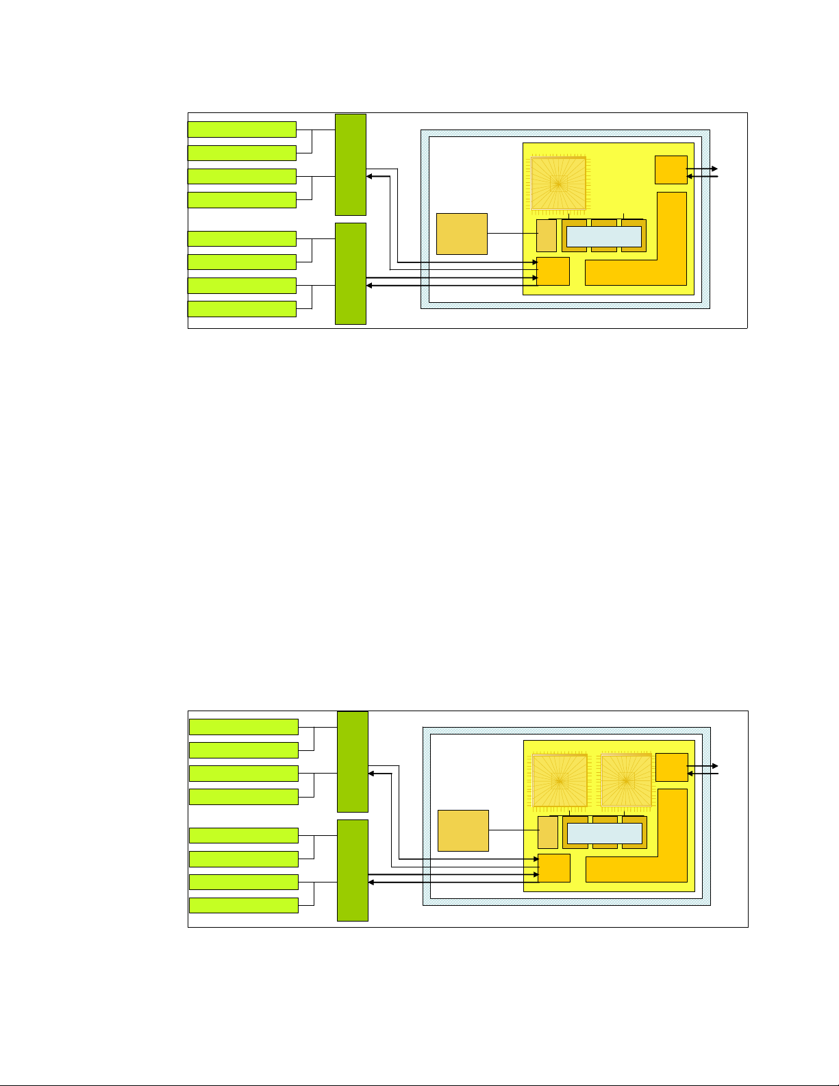
DIMM
DIMM
DIMM
DIMM
DIMM
DIMM
DIMM
DIMM
DIMM
DIMM
DIMM
DIMM
DIMM
DIMM
DIMM
DIMM
@528 MHz
@528 MHz
2 x 8 B
2 x 8 B
SMI-II SMI-II
SMI-II SMI-II
1056 MHz
1056 MHz
2 x 8 B for read
2 x 8 B for read
2 x 2 B for write
2 x 2 B for write
Single-Core Module
Single-Core Module
SCM
SCM
2x16B
2x16B
2:1
36 MB
36 MB
L3 cache
L3 cache
2:1
POWER5+
POWER5+
POWER5+
core
core
core
L3
L3
Ctrl
Ctrl
Mem
Mem
Ctrl
Ctrl
1.9 MB Shared
1.9 MB Shared
L2 cache
L2 cache
Enhanced distributed s witch
Enhanced distributed s witch
GX+
GX+
Ctrl
Ctrl
GX+
GX+
Bus
Bus
Figure 2-4 p5-520 POWER5+ 2.1 GHz SCM with DDR2 memory socket layout view
The storage structure for the POWER5+ processor is a distributed memory architecture that
provides high-memory bandwidth. The processor is interfaced to eight memory slots that are
controlled by two Synchronous Memory Interface II (SMI-II) chips, which are located in close
physical proximity to the processor module.
I/O connects to the p5-520 processor module using the GX+ bus. The processor module
provides a single GX+ bus. The GX+ bus provides an interface to I/ O devices through the
RIO-2 connections.
The theoretical maximum throughput of the L3 cache is 16 byte read, 16 byt e write at a bus
frequency of 1.05 GHz (based on a 2.1 GHz processor cloc k), which equ ates to 33 600 MBps
or 33.60 GBps. Additional throughput details are provided in Table 2-3 on page 33.
2.2.2 The p5-520 POWER5+ dual-core module
The 2-core p5-520 system planar contains a dual-core module (DCM) and the local memory
storage subsystem for that DCM. The POWER5+ dual-core processor and its associated L3
cache are packaged in the DCM.
Figure 2-5 on page 28 shows a layout view of p5-520 DCM and associated memory.
DIMM
DIMM
DIMM
DIMM
DIMM
DIMM
DIMM
DIMM
@528 MHz
@528 MHz
DIMM
DIMM
DIMM
DIMM
DIMM
DIMM
DIMM
DIMM
Figure 2-5 The p5-520 POWER5+ 2.1 GHz DCM with DDR2 memory socket layout view
The storage structure for the POWER5+ processor is a distributed memory architecture that
provides high-memory bandwidth, although each processor can address all memory and
2 x 8 B
2 x 8 B
SMI-II SMI-II
SMI-II SMI-II
1056 MHz
1056 MHz
2 x 8 B for read
2 x 8 B for read
2 x 2 B for write
2 x 2 B for write
DCM
DCM
36 MB
36 MB
L3 cache
L3 cache
2x16B
2x16B
@1.05 GHz
@1.05 GHz
POWER5+
POWER5+
POWER5+
core
core
core
2.1 GHz
2.1 GHz
2.1 GHz
L3
L3
Ctrl
Ctrl
Mem
Mem
Ctrl
Ctrl
POWER5+
POWER5+
POWER5+
core
core
core
2.1 GHz
2.1 GHz
2.1 GHz
1.9 MB Shared
1.9 MB Shared
L2 cache
L2 cache
Enhanced distributed switch
Enhanced distributed switch
GX+
GX+
Ctrl
Ctrl
GX+
GX+
Bus
Bus
28 IBM System p5 520 and 520Q Technical Overview and Introduction
Page 43

sees a single shared memory resource. They are interfaced to eight memory slots, controlled
by two SMI-II chips, which are located in close physical proximity to th e processor modules.
I/O connects to the p5-520 processor module using the GX+ bus. The processor module
provides a single GX+ bus. The GX+ bus provides an interface to I/ O devices through the
RIO-2 connections.
The theoretical maximum throughput of the L3 cache is 16 byte read, 16 byt e write at a bus
frequency of 1.05 GHz (based on a 2.1 GHz processor cloc k), which equ ates to 33 600 MBps
or 33.60 GBps. Additional throughput details are provided in Table 2-3 on page 33.
2.2.3 The p5-520Q quad-core module
The 4-core p5-520Q system planar contains a ne w quad-core module (QCM) and the local
memory storage subsystem for that QCM. Two POWER5+ dual-core processors and their
associated L3 cache are packaged in the QCM.
Figure 2-6 shows a layout view of a p5-520Q QCM with associated memory.
2x 8B
2x 8B
@528 MHz
@528 MHz
DIMM
DIMM
DIMM
DIMM
DIMM
DIMM
DIMM
DIMM
DIMM
DIMM
DIMM
DIMM
DIMM
DIMM
DIMM
DIMM
SMI-II SMI-II
SMI-II SMI-II
1056 MHz
1056 MHz
2 x 8B for read
2 x 8B for read
2 x 2B for write
2 x 2B for write
QCM
QCM
L3 cache
L3 cache
L3 cache
L3 cache
36 MB
36 MB
36 MB
36 MB
2 x 16B
2 x 16B
@825 MHz
@825 MHz
2 x 16B
2 x 16B
@825 MHz
@825 MHz
Mem
Mem
ctrl
ctrl
Mem
Mem
ctrl
ctrl
ctrl
ctrl
L3
L3
ctrl
ctrl
Core
Core
1.65 GHz
1.65 GHz
L3
L3
Core
Core
Core
1.65 GHz
1.65 GHz
1.65 GHz
Core
Core
1.65 GHz
1.65 GHz
1.9 MB
1.9 MB
L2 cache
L2 cache
Enhanced
Enhanced
distributed switch
distributed switch
Enhanced
Enhanced
distributed switch
distributed switch
1.9 MB
1.9 MB
L2 cache
L2 cache
Core
Core
Core
1.65 GHz
1.65 GHz
1.65 GHz
GX+
GX+
GX+
Ctrl
Ctrl
Ctrl
GX+
GX+
GX+
Ctrl
Ctrl
Ctrl
GX+
GX+
Bus
Bus
Figure 2-6 The p5-520Q POWER5+ 1.65 GHz QCM with DDR2 memory socket layout view
The storage structure for the POWER5+ processor is a distributed memory architecture that
provides high-memory bandwidth. Each processor in the QCM can address all memory and
see a single shared memory resource. In the QCM, one POWER5+ processor has direct
access to eight memory slots, controlled by two SMI-II chips, which are located in close
physical proximity to the processor modules. The other POWER5+ processor has access to
the same memory slots through the Vertical Fabric Bus.
I/O connects to the p5-520Q QCM using the GX+ b us. The QCM provides a single GX+ bus.
One POWER5+ processor has direct acce ss to the GX+ Bus using its GX+ Bus controller and
the other uses the Vertical Fabric Bus controlled by the Fabric Bus controller. The GX+ bus
provides an interf ace to I/O devices through the RIO-2 connections.
The POWER5+ processor, without direct access to memory, does have a direct access to the
GX+ Bus.
The theoretical maximum throughput of the L3 cache is 16 byte read, 16 byt e write at a bus
frequency of 825 MHz (based on a 1.65 GHz processor clock), which equates to 26400 MBps
or 26.4 GBps per L3 cache. There are two L3 caches on the QCM, which provide a total L3
cache bandwidth of 52800 MBps or 52.8 GBps per QCM. Additional throughput details are
provided in Table 2-3 on page 33.
Chapter 2. Architecture and technical overview 29
Page 44

2.2.4 Available processor speeds
Table 2-1 lists the avail able processor capacities and speeds for the p5-520 and p5-520Q
systems.
Table 2-1 p5-520 and p5-520Q available processor capacities and speeds
p5-520 @
1.65 GHz
1-core Yes No Yes No No
2-core Yes Yes Yes No No
4-core No No No Yes Yes
p5-520 @
1.9 GHz
p5-520 @
2.1 GHz
p5-520Q @
1.5 GHz
p5-520Q @
1.65 GHz
To determine the processor character is tics, use one of th e following commands:
lsattr -El procX
In this command, X is the number of the processor. For example, proc0 is the first
processor in the system. The output from the command is similar to the following output
(False, as used in this output, signifies that the value cannot be changed through an AIX
5L command interface):
frequency 1498500000 Processor Speed False
smt_enabled true Processor SMT enabled False
smt_threads 2 Processor SMT threads False
state enable Processor state False
type powerPC_POWER5 Processor type False
pmcycles -m
The pmcycles command (AIX 5L) uses the performance monitor cycle counter and the
processor real-time clock to measure the actual processor clock speed in MHz. The
following output is from a 4- core p5-520Q system running at 1.5 GHz with simultaneous
multithreading enabled:
Cpu 0 runs at 1498 MHz
Cpu 1 runs at 1498 MHz
Cpu 2 runs at 1498 MHz
Cpu 3 runs at 1498 MHz
Note: The pmcycles command is part of the bos.pmapi fileset. This component must be
installed before using the lslpp -l bos.pmapi command.
2.3 Memory subsystem
The p5-520 and p5-520Q servers offer pluggable DDR2 DIMMs for memory. DDR2 DIMM s
have a double rate compared with DDR DIMMs (DDR DIMMs have double rate bits
compared with SDRM), so that enables up to four times the performance of traditional
SDRAM. The system planar provides eight slots for up to eight pluggable DDR2 DIMMs.
The minimum memory for a p5-520 or p5-520Q server is 1.0 GB (2 x 512 MB) and 32 GB is
the maximum installable memory option. Figure 2-7 shows the memory slot and location
codes. All memory is accessed by two Synchron ous Mem ory Interface (SMI)-II chips that are
located between the memory and the processor. The SMI-II supports multiple data flow
modes.
30 IBM System p5 520 and 520Q Technical Overview and Introduction
Page 45

DIMM CX JXX “Ax”
DIMM CX JXX “Ax”
DIMM CX JXX “Ax”
DIMM CX JXX “Ax”
DIMM CX JXX “Ax”
DIMM CX JXX “Ax”
DIMM CX JXX “Ax”
DIMM CX JXX “Ax”
DIMM CX JXX “Ax”
DIMM CX JXX “Ax”
DIMM CX JXX “Ax”
DIMM CX JXX “Ax”
DIMM CX JXX “Ax”
DIMM CX JXX “Ax”
DIMM CX JXX “Ax”
DIMM CX JXX “Ax”
First quad Second quad
First quad Second quad
J2A
J2A
J2B
J2B
J2C
J2C
J2D
J2D
J0D
J0D
J0C
J0C
J0B
J0B
J0A
J0A
@528 MHz
@528 MHz
2x8 B
2x8 B
DIMM CX JXX “Ax”
DIMM CX JXX “Ax”
DIMM CX JXX “Ax”
DIMM CX JXX “Ax”
DIMM CX JXX “Ax”
DIMM CX JXX “Ax”
DIMM CX JXX “Ax”
DIMM CX JXX “Ax”
DIMM CX JXX “Ax”
DIMM CX JXX “Ax”
DIMM CX JXX “Ax”
DIMM CX JXX “Ax”
DIMM CX JXX “Ax”
DIMM CX JXX “Ax”
DIMM CX JXX “Ax”
DIMM CX JXX “Ax”
1056 MHz
2x8 B for read
2x8 B for write
1056 MHz
2x8 B for read
2x8 B for write
SMI-II SMI-II
SMI-II SMI-II
POWER5+
POWER5+
DCM (Dual-Core Module)
DCM (Dual-Core Module)
or
or
QCM (Quad-Core Module)
QCM (Quad-Core Module)
SMI-II
SMI-II
@528 MHz
@528 MHz
2x8 B
2x8 B
SMI-II
SMI-II
Figure 2-7 Memory placement for the p5-520 and p5-520Q ser vers
2.3.1 Memory placement rules
Table 2-2 lists the memory features that are a vailable at the time of writing f or the p 5-520 and
p5-520Q servers.
Table 2-2 Av ailable memory features
Feature code Description
1930 1 GB (2 x 512 MB) DIMMs, 276-pin DDR2, 533 MHz SDRAM
1931 2 GB (2 x 1 GB) DIMMs, 276-pin DDR2, 533 MHz SDRAM
1932 4 GB (2 x 2 GB) DIMMs, 276-pin DDR2, 533 MHz SDRAM
1934 8 GB (2 x 4 GB) DIMMs, 276-pin DDR2, 533 MHz SDRAM
Memory can be pluggable in pairs or quads, as required by the total memory requirement.
Memory feature numbers might be mixed within a system. The DIMMs slots are accessed by
first removing the PCI riser book.
When additional memory is added to a system using FC 1930, an additional feature, FC
1930, must be added to the original pair to make a quad, allowing one additional quad to be
added to the system. Memory is installed in the first quad in the f ollowing order: J2A, J0A,
J2C, and J0C; and for the second quad, in the order J2B, J0B, J2D, and J0D. Memory must
be balanced across the DIMM quad slots. The Service Information label, located on the top
cover of the system, provides memory DIMMs slot location information.
Chapter 2. Architecture and technical overview 31
Page 46

To determine how much memory is installed in a system, use the following command:
# lsattr -El sys0 | grep realmem
realmem 524288 Amount of usable physical memory in Kbytes False
Note: A quad must consist of a single feature (that is, be made of identical DIMMs). Mixed
DIMM capacities in a quad will result in reduced RAS.
2.3.2 OEM memory
OEM memory is not supported or certified by IBM for use in an IBM System p5 server. If the
server is populated with OEM memory, you could experience unexpected and unpredictable
behavior, especially when the system is using Micro-Partitioning technology.
All IBM memory is identified by an IBM logo and a white label that is printed with a barcode
and an alphanumeric string, as illustrated in Figure 2-8.
Figure 2-8 IBM memory certification label
2.3.3 Memory throughput
The memory subsystem throughput is based on the speed of the memory. An elastic
interface, contained in the POWER5+ processor, buffers reads and writes to and from
memory and the processor. There are two Synchronous Memory Interface (SMI-II) chips,
each with a single 8-byte read and 2-byte write high speed Elastic Interface-II bus to the
memory controller of the processor. The bus allows double reads or writes per clock cycle.
Because the bus operates at 1066 MHz, the peak processor-to-memory throughput for read
is (8 x 2 x 1056) = 16896 MBps or 16.89 GBps. The peak processor-to-memory throughput
for write is (2 x 2 x 1056) = 4224 MBps or 4.22 GBps, making a total of 21.12 GBps.
The 533 MHz DDR2 memory DIMMS operate at 528 MHz through four 8-byte paths. Read
and write operations share these paths. There must be at least four DIMMs installed to
effectively use each path. In this case, the throughput between the SMI-II and the DIMMs is
(8 x 4 x 528) or 16.89 GBps.
These values are maximum theoretical throughputs for comparison purposes only. Table 2-3
provides the theoretical throughput values for different configurations.
32 IBM System p5 520 and 520Q Technical Overview and Introduction
Page 47

Table 2-3 Theoretical throughput rates
Processor speed
(GHz)
1.65 POWER5+ 1-core 21.1 26.4 4.4
1.65 POWER5+ 2-core 21.1 26.4 4.4
1.9 POWER5+ 2-core 21.1 30.4 5.1
2.1 POWER5+ 1-core 21.1 33.6 5.6
2.1 POWER5+ 2-core 21.1 33.6 5.6
1.5 POWER5+ 4-core 21.1 48 4
1.65 POWER5+ 4-core 21.1 52.8 4.4
2.4 I/O buses
This section provide additional inf ormation that is related to the internal RIO-2 bu ses and GX+
buses.
The QCM or DCM provides a GX+ bus. In the past, the 6XX bus was the front end from the
processor to memory, PCI Host bridge, cache, and other devices. The follow-on to the 6XX
bus is the GX bus, connecting the processor to the I/O subsystems. Compared with the 6XX
bus, the GX+ bus is both wider and faster and connects to the Enhanced I/O Controller.
Processor Type Cores Memory
(GBps)
L2 to L3
(GBps)
GX+
(GBps)
The Enhanced I/O Controller is a GX+ to PCI and PCI-X 2.0 Host bridge chip. It contains a
GX+ passthru port and four PCI-X 2.0 buses. The GX+ passthru port allows other GX+ bus
hubs to be connected into the system. Each Enhanced I/O Controller can provide four
separate PCI-X 2.0 buses. Each PCI-X 2.0 bus is 64 bits in width and individually capable of
running either PCI, PCI-X, or PCI-X 2.0 (DDR only).
The p5-520 and p5-520Q systems do not ha ve RIO-2 ports integrated on the system planar
to connect supported external I/O subsystems. As shown in Figure 2-9 on page 34, one
Remote I/O expansion card (FC 2888) is required to connect the supported external I/O
subsystems. When this card is present, the Enhanced I/O Controller routes the GX+ bus to
the external RIO-2 por ts.
Chapter 2. Architecture and technical overview 33
Page 48
External
External
I/O
I/O
Subsystem
Subsystem
(up to 4
(up to 4
7311-D20)
7311-D20)
RIO-2
RIO-2
Card
Card
GX+
GX+
Bus
Bus
DCM
DCM
or
or
QCM
QCM
Memory
Memory
Processor Card
Processor Card
Enhanced
Enhanced
I/O
I/O
Controller
Controller
System Planar
System Planar
Internal
Internal
I/O
I/O
Subsystem
Subsystem
Figure 2-9 p5-520 or p5-520Q GX+ Bus connection overview
According to the processor speed, the I/O subsystem is capable of supporting 5.6 GBps
when using the 2.1 GHz processor, or capable of supporting 4.4 GBps when using a 1.65
GHz processor. The bus is a dual four-byte wide bus running at a 3:1 processor to bus ratio.
2.5 Internal I/O subsystem
PCI-X, where the X stands for extended, is an enhanced PCI bus, delivering a bandwidth of
up to 2 GBps, running a 64-bit bus at 133 MHz or 266 MHz. PCI-X is backward compatible,
so the systems can support existing 3.3 volt PCI adapters.
The system planar provides six PCI-X slots and several integrated I/O devices. The PCI-X
slot 1, slot 5, and slot 6 are 64-bit capable running at 133 MHz. The PCI-X slot 2 and slot 3
are 32-bit capable running at 66 MHz, but PCI-X 64-bit short adapters can be used in these
slots.
All the PCI-X slots and the integrated I/O devices, except the PCI-X slot 4, are connected
through two EADS-X chips that function as PCI-X to PCI-X bridges to the Enhanced I/ O
Controller. The connections of the PCI-X slots and integrated I/O devices to the PCI-X to
PCI-X bridges are properly distributed to maximize the system performances.
The first three PCI-X slots can accept a short PCI-X or PCI card. The remaining PCI-X slots
are full length cards. PCI-X slot 4 is a PCI-X DDR 266 MHz and 64 bit capable slot and is
driven by the Enhanced I/O Controller directly. The dual 10/100/1000 Mbps Ethernet adapter
and the Dual Channel SCSI Ultra320 adapter are some of the integrated devices on the
system planar.
The PCI-X slots in the p5-520 and p5-520Q system support hot-plug and Extended Error
Handling (EEH). In the unlikely event of a problem, EEH-enabled adapters respond to a
special data packet generated from the affected PCI-X slot hardware by calling system
firmware, which will examine the affected b us , allow the device driver to reset it, and continue
without a system reboot.
34 IBM System p5 520 and 520Q Technical Overview and Introduction
Page 49

2.6 64-bit and 32-bit adapters
IBM offers 64-bit adapter options for the p5-520 and p5-52 0Q, as well as 32-bit adapters.
Higher-speed adapters use 64-bit slots because they can transfer 64 bits of data for each
data transfer phase. Generally, 32-bit adapters can function in 64-bit PCI-X slots; however,
some 64-bit adapters cannot be used in 32-bit slots. For a full list of the adapters that are
supported on the systems and for important information regarding adapter placement, see
the IBM Systems Hardware Information Center at:
http://publib.boulder.ibm.com/infocenter/eserver/v1r3s/index.jsp
The internal PCI-X slots support a wide range of PCI-X I/O adapters to handle your I/O
requirements.
2.6.1 LAN adapters
To connect a p5-520 or p5-520Q to a local area network (LAN), you can use the dual port
internal 10/100/1000 M bps RJ-45 Ethernet controller that is integrated on the system planar.
Table 2-4 lists the additional LAN adapters that are available for an initial system order at the
time of writing. IBM supports an installation with NIM using Ethernet and token-ring adapters
(CHRP
Table 2-4 Av ailable LAN adapters
1
is the platform type). Token-ring is not allowed as the initial order.
Feature code Adapter description Type Slot Size Max
1954 4-port 10/100/1000 Ethernet Copper 32 or 64 Short 4
1978 Gigabit Ethernet Fibre 32 or 64 Short 6
1979 Gigabit Ethernet Copper 32 or 64 Short 6
5721 10 Gigabit Ethernet - short reach Fibre 32 or 64 Short 3
5722 10 Gigabit Ethernet - long reach Fibre 32 or 64 Short 3
1983 2-port Gigabit Ethernet Copper 32 or 64 Short 6
1984 2-port Gigabit Ethernet Fibre 32 or 64 Short 6
2.6.2 SCSI adapters
To connect to external SCSI devices, the adapters that are pr ovided in Table 2-5 are available ,
at the time of writing, to be configured with an initial order.
Table 2-5 Available SCSI adapters
Feature code Adapter description Slot Size Max
1912 Dual Channel Ultra320 SCSI 64 Short 6
1913 Dual Channel Ultra320 SCSI RAID 64 Long 3
Note: Previous SCSI adapters are also supported for use in the p5-520 and p5-520Q but
cannot be part of an initial order configuration. If you want to connect existing external
SCSI devices, contact your IBM service representative.
1
CHRP stands for Common Hardware Reference Platform, a specification for PowerPC-based systems that can
run multiple operating systems.
Chapter 2. Architecture and technical overview 35
Page 50

You also have the option to mak e the inte rnal Ultra320 SCSI channel e xternally accessible on
the rear side of the system by installing FC 4275. No additional SCSI adapter is required in
this case. If FC 4275 is installed, a second 4-pack disk enclosure (FC 6574 or FC 6594)
cannot be installed, which limits the maximum number of internal disks to four. Slot 5 cannot
be used when FC 4275 is installed. For more inf ormation about the internal SCSI system, see
2.7, “Internal storage” on page 41.
2.6.3 Integrated RAID options
The p5-520 and p5-520Q can be configured with the optional SCSI RAID daughter card
(FC 1907) that plugs directly on the system board or with a Dual Channel Ultra320 SCSI
RAID adapter (FC 1913) to drive one 4-pack disk enclosure.
RAID implementation requires a minimum of three disk drives to form a RAID set.
Important: RAID Capacity limitation. There are limits to the amount of disk drive capacity
allowed in a single RAID array. Using the 32-bit AIX 5L kernel, there is a capacity limitation
of 1 TB per RAID array. Using the 64 bit kernel, there is a capacity limitation of 2 TB per
RAID array. For RAID adapter and RAID enablement cards, this limitation is enforced by
AIX 5L when RAID arrays are created using the PCI-X SCSI Disk Array Manager.
These are different internal RAID options that you can consider:
Install FC 1907 and up to 4 disk drives in the default 4-pack disk enclosure. This allows
RAID capabilities within a single 4-pack.
Install FC 1907 and a second 4-pack disk enclosure (FC 6574). This allows RAID
capabilities across two 4-packs.
2.6.4 iSCSI
Install FC 1907 (or later) and the Ultra320 SCSI 4-Pack Enclosure for Disk Mirroring
(FC 6594). Install the PCI-X Dual Channel Ultra320 SCSI RAID adapter (FC 1913) and
the SCSI cable (FC 4267), which connects the PCI-X adapter to the optional 4-pack disk
enclosure. This RAID configuration provides increased reliability over first and second
options
Note: Because the p5-520 and p5-520Q have up to eight disk drive slots, if you are
upgrading, you mu st plan appr opriately to ensure th e correct handling of your RAID arrays.
iSCSI is an open, standards-based approach by which SCSI information is encapsulated
using the TCP/IP protocol to allow its transport over IP networks. It allows transfer of data
between storage and servers in b lock I/O formats (that is defined by iSCSI protocol) and thus
enables the creation of IP SANs. iSCSI allows an existing network to transfer SCSI
commands and data with full location independence and defines the rules and processes to
accomplish the communication. The iSCSI protocol is defined in iSCSI IETF draft-20. For
more information about this standard, see:
http://tools.ietf.org/html/rfc3720
Although iSCSI can be, by design, supported over any physical media that supports TCP/IP
as a transport, today's implementations ar e on ly on Gigabit Ethe rnet. At the physical and link
level la y ers , iSCSI supports Gigabit Ethernet and its frames so t hat systems supporting iSCSI
can be directly connected to standard Gigabit Ethernet switche s and IP routers. iSCSI also
enables the access to block-level storage that resides on Fibre Channel SANs over an IP
network using iSCSI-to-Fibre Channel gateways such as storage routers and switches.
36 IBM System p5 520 and 520Q Technical Overview and Introduction
Page 51

The iSCSI protocol is implemented on top of the ph ysical and data -link la y ers and present s to
the operating system a standard SCSI Access Method command set. It supports SCSI-3
commands and reliable delivery over IP networks. The iSCSI protocol runs on the host
initiator and the receiving target device. It can either be optimized in hardware for better
performance on an iSCSI host b u s ada pter (such as FC 19 86 and FC 19 87 su pported in IBM
System p5 servers) or run in software over a standard Gigabit Ethernet network interface
card. IBM System p5 systems support iSCSI in the following two modes:
Hardware Using iSCSI adapt ers (see “IBM iSCSI adapters” on page 37).
Software Supported on standard Gigabit adapters, additional software (see
“IBM iSCSI software Host Support Kit” on page 38) must be installed.
The main processor is utilized for processing related to the iSCSI
protocol.
Initial iSCSI implementations are targeted at small to medium-sized businesses and
departments or branch offices of larger enterprises that have not deployed Fibre Channel
SANs. iSCSI is an affordab le wa y to create I P SANs from a number of local or remote stor age
devices. If Fibre Channel is present, which is typical in a data center, it can be accessed by
the iSCSI SANs (and vice versa) via iSCSI-to-Fibre Channel storage routers and switches.
iSCSI solutions always involve the following software and hardware components:
Initiators These are the device drivers and adapters that reside on the client.
They encapsulate SCSI commands and route them over the IP
network to the target device.
Targets The target software receives the encapsulated SCSI commands over
the IP network. The software can also provide configuration support
and storage-management support. The underlying target hardware
can be a storage appliance that contains embedded storage, and it
can also be a gateway or bridge product that contains no internal
storage of its own.
IBM iSCSI adapters
New iSCSI adapters in IBM System p5 systems provide the advantage of increased
bandwidth through the hardware support of the iSCSI protocol. The 1 Gigabit iSCSI TOE
(TCP/IP Offload Engine) PCI-X adapters support hardware encapsulatio n of SCSI commands
and data into TCP and transports them over the Ethernet using IP packets. The adapter
operates as an iSCSI TOE. This offload function eliminates host protocol processing and
reduces CPU interrupts. The adapter uses a Small form factor LC type fiber optic connector
or a copper RJ45 connector.
Table 2-6 provides the orderable iSCSI adapters.
Table 2-6 provides the orderable iSCSI adapters.
Table 2-6 Av ailable iSCSI adapters
Feature
code
1986 Gigabit iSCSI TOE PCI-X on copper media adapter 64 Short 3
Description Slot Size Max
1987 Gigabit iSCSI TOE PCI-X on optical media adapter 64 Short 3
Chapter 2. Architecture and technical overview 37
Page 52

IBM iSCSI software Host Support Kit
The iSCSI protocol can also be used over standard Gigabit Ethernet adapters. To utilize this
approach, download the appropriate iSCSI Host Support Kit for your operating system from
the IBM NAS support Web site at:
http://www.ibm.com/storage/support/nas/
The iSCSI Host Support Kit on AIX 5L and Linux acts as a software iSCSI initiator and allows
you to access iSCSI target storage devices using standard Gigabit Ethernet network
adapters. To ensure the best performance, enable the TCP Large Send, TCP send and
receive flow control, and Jumbo Frame features of the Gigabit Ethernet Adapter and the
iSCSI Target. Tune network options and interface parameters for maximum iSCSI I/O
throughput on the operating system.
IBM System Storage N series
The combination of IBM System p5 and IBM System Storage™ N series as the first of a
whole new generation of iSCSI-enabled storage products provides an End-to-End set of
solutions. Currently, the System Storage N series feature three models: N3700, N5200, and
N5500.
All models provide:
Support for entry-level and m idra nge clients req uiring Network Attached Sto rage (NAS) or
Internet Small Computer System Interface (iSCSI) functi onality
Support for Network File System (NFS), Common Internet File System (CIFS), and iSCSI
protocols
Data ONTAP software (at no charge), with plenty of additional functions such as data
movement, consistent snapshots, and NDMP server protocol, some available through
optional licensed functions
Enhanced reliability with optional clustered (2-node) failover support
2.6.5 Fibre Channel adapter
The p5-520 and p5-520Q servers support direct or SAN connection to devices using Fibre
Channel adapters. Single-port Fibre Channel adapters are available in 2 Gbps and 4 Gbps
speeds. A dual-port 4 Gbps Fibre Channel adapter is also ava ilable. Table 2-7 provides a
summary of the available Fibre Channel adapters.
All of these adapters have LC connectors. If you are attaching a device or switch with an SC
type fibre connector , then an LC-SC 50 Micro n Fiber Conv erter Cable (FC 2456) or an LC-SC
62.5 Micron Fiber Converter Cable (FC 2459) is required.
Supported data rates between the server and the attached device or switch are as follows:
Distances of up to 500 meters running at 1 Gb ps, distanc es up to 30 0 me te rs running at
2 Gbps data rate, and distances up to 150 meters running at 4 Gbps. When these adapters
are used with IBM supported Fibre Channel storage switches supporting long-wave optics,
distances of up to 10 kilometers are capable running at 1 Gbps, 2 Gbps, and 4 Gbps data
rates.
38 IBM System p5 520 and 520Q Technical Overview and Introduction
Page 53

Table 2-7 Available Fibre Channel adapters
Feature
code
1905 4 Gigabit single-port Fibre Channel PCI-X 2.0 Adapter (LC) 64 Short 6
1910 4 Gigabit dual-port Fibre Channel PCI-X 2.0 Adapter (LC) 64 Short 6
1977 2 Gigabit Fibre Channel PCI-X Adapter (LC) 64 Short 6
Description Slot Size Max
2.6.6 Graphic accelerators
The p5-520 and p5-520Q support up to four enhan ced POWER GXT135P (FC 1980) 2D
graphic accelerators. The POWER GXT135P is a low-priced 2D graphics accelerator for
IBM System p5 servers. This adapter supports both analog and digital monitors and is
supported for System Management Services (SMS), firmware, and other functions , as well as
when AIX 5L or Linux starts an X11-based graphic user interface (GUI).
2.6.7 InfiniBand Host Channel adapter
The p5-520 and p5-520Q support the RIO-2 expansion cards (FC 2888) to connect the
supported additional I/O subsystems. The server also supports one GX Dual-port 4x
InfiniBand Host Channel Adapter (FC 1812 ) that enables the attachment of the Topspin
Server Switch models 120 and 270. Only a single GX Dual-port 4x InfiniBand HCA or RIO-2
expansion card can plug into the system planar, using the GX slot, at a time. Connection to
the Topspin Server Switches is accomplished by using the 4x IB Cables.
Topspin Server Switch models 120 and 270
Switches are the fundamental components of an InfiniBand fabric. An IBM System p5 server
proposal might also include the Topspin Server Switch model 120 and 270 in an initial system
order.
The Topspin Server Switch models 120 and 270 are programmable switching platforms that
consist of a switched multiple-terabit interconnect and an intelligent control architecture. The
high-bandwidth, low-latency interconnection is extremely adaptable. The switches enable an
outstanding level of application scaling, rapid deployment, and resource conso lidation.
For more information about Topspin Server Switch, see:
http://www.topspin.com/solutions/
2.6.8 Asynchronous PCI-X adapters
Asynchronous PCI-X adapters provide connection of asynchronous EIA-232 or RS-422
devices. If you have a cluster configuration or high-availability configuration and plan to
connect the IBM System p5 servers using a serial connection, the use of the tw o def ault po rts
is not supported. You should use one of the features listed in Table 2-8.
Table 2-8 Asynchronous PCI-X adapters
Feature code Description
2943 8-Port Asynchronous Adapter EIA-232/RS-422
5723 2-Port Asynchronous IEA-232 PCI Adapter
Chapter 2. Architecture and technical overview 39
Page 54

In many cases, the 5723 asynchronous adapter is configured to supply a backup HACMP
heartbeat. In these cases, a serial cable (FC 3927 or FC 3928) m ust be also configured. Bo th
of these serial cables and the 5723 adapter have 9-pin connectors.
2.6.9 PCI-X Cryptographic Coprocessor
The PCI-X Cryptographic Coprocessor (FIPS 4) (FC 4764) for selected System p servers
provides both cryptographic coprocessor and secure-key cryptographic accelerator functions
in a single PCI-X card. The coprocessor functions are targeted to banking and finance
applications. Financial PIN processing and credit card functions are provided. EMV is a
standard for integrated chip-based credit cards. The securek ey accelerator functions are
targeted to improving the performance of Secure Sockets Layer (SSL) transactions. The
FC 4764 provides the security and performance required to support On Demand Business
and emerging digital signature application.
The PCI-X Cryptographic Coprocessor (FIPS 4) (FC 4764) for selected System p servers
provides both cryptographic coprocessor and secure-key cryptographic accelerator functions
in a single PCI-X card. The FC 4764 provides secure storage of cryptographic keys in a
tamper resistant hardware secu rity module (HSM), which is designed to meet FIPS 140
security requirements. FIPS 140 is a U.S. Government National Institute of Standards &
Technology (NIST)-administered standard and certification program for cryptographic
modules. The firmware for the FC 4764 is available on a separately ordered and distributed
CD. This firmware is an LPO product: 5733-CY1 Cryptographic Device Manager. The FC
4764 also requires LPP 5722-AC3 Cryptographic Access Provider to enable data encryption.
Note: This feature has country-specific usage. Refer to the IBM representatives in your
country for availability or restrictions.
2.6.10 Additional support for PCI-X adapters you own
The lists of the major PCI-X adapters that you can configure in a p5-520 or p5-520Q when
you build an initial conf iguration order are described in 2.6.1, “LAN adapters” on page 35
through 2.6.8, “Asynchronous PCI-X adapters” o n page 39. The list of all the supported PCI-X
adapters, with the related support for additional external devices, is more extended.
If you would like to use PCI-X adapters you already own, contact your IBM service
representative to verify whether those adapters are supported.
2.6.11 Internal system ports
The system ports S1 and S2, at the rear of the system, are only available if the system is not
managed using a Hardware Management Console (HMC). In this case, the S1 and S2 ports
support the attachment of a serial console and a modem and are of limited function.
If an HMC is connected, a
under AIX 5L), and you can also conne ct a modem t o the HMC. The S1 and S2 ports are not
usable in this case.
If you need serial port function, optional PCI adapters are available. For more information,
see 2.6.8, “Asynchronous PCI-X adapters ” on pag e 39.
virtual serial console is provided by the HMC (logical device vsa0
40 IBM System p5 520 and 520Q Technical Overview and Introduction
Page 55

2.6.12 Ethernet ports
The two built-in Ethernet ports provide 10/100/1000 Mbps connectivity over CAT-5 cable for
up to 100 meters. Table 2-9 lists the attributes of the LEDs that are visib le on the side of the
jack.
Table 2-9 Ethernet LED descriptions
LED Light Description
Link Off
Green
Activity On
Off
2.7 Internal storage
There is one dual channel Ultra320 SCSI controller that is managed by the EADS-X chips,
integrated into the system planar, and that is used to drive the internal disk drives. The eight
internal drives plug into the disk drive backplane, which has two separate SCSI buses with
four disk drives per bus.
The internal disk drive can be used in two different modes based on whether the SCSI RAID
Enablement Card (FC 1976) is installed (see 2.6.3, “Integrated RAID options” on page 36).
The p5-520 and p5-520Q supports two 4-pack disk drives using a bac k plane that is d esigned
for hot-pluggable disk drives. The disk drive backplane docks directly to the system planar.
The virtual SCSI Enclosure Services (VSES) hot-plug control functions are provided by the
Ultra320 SCSI controllers.
2.7.1 Internal media devices
No link; could indicate a bad cable, not selected, or configuration
error.
Connection established.
Data activity.
Idle.
The p5-520 and p5-520Q provide two slim-line media bays for optional DVD-ROM (FC 1994)
and optional DVD-RAM (FC 1993) and one media bay for a tape drive. Table 2-10 shows all
additional media devices for the systems.
Table 2-10 Available optical and tape drives
Feature code Description
1993 4.7 GB IDE Slimline DVD-RAM drive
1994 IDE Slimline DVD-ROM drive
1892 VXA-320 160/320 GB Internal Tape Drive
1991 36/7 2 GB 4 mm Internal Tape Drive
1992 IBM 80/1 60 GB Internal Tape Drive with VXA Technology
1997 200/400 GB Half High Ultrium 2 Tape Drive
2.7.2 Internal hot-swappable SCSI disks
The p5-520 and p5-520Q can have up to eight hot-swappable disk drives plugged in the two
4-pack disk drive backplanes. The hot-swappable process is controlled by the SCSI
enclosure service (SES), which is located in the 4-pack disk drives backplane (AIX 5L
Chapter 2. Architecture and technical overview 41
Page 56

assigns the name ses0 to the first 4-pack, and ses1 to the second, if present). The two
hot-swappable 4-pack disk drive backplanes can accommodate the devices listed in
Table 2-11.
Table 2-11 Available hot-swappable disk drives
Feature code Description
1968 73.4 GB ULTRA320 10 K rpm SCSI hot-swappable disk drive
1969 146.8 GB ULTRA320 10 K rpm SCSI hot-swappable disk drive
1970 36.4 GB ULTRA320 15 K rpm SCSI hot-swappable disk drive
1971 73.4 GB ULTRA320 15 K rpm SCSI hot-swappable disk drive
1972 146.8 GB ULTRA320 15 K rpm SCSI hot-swappable disk drive
1973 300 GB ULTRA320 10 K rpm SCSI hot-swappable disk drive
At the time of writing, if a new order is placed with two 4-pa ck DASD backplanes (FC 6574)
and more than one disk, the system configuratio n shipped from manufacturing balances the
total number of SCSI disks between the two 4-pack SCSI backplanes. This is for
manufacturing test purposes and not because of any limit ation. Having the disks balanced
between the two 4-pack DASD backplanes allows the manufacturing process to
systematically test the SCSI paths and devices related to them.
Prior to the hot-swap of a disk in the hot-swap capable bay, all necessary operating system
actions must be undertaken to ensu re that the disk is capab le of bein g deconfigured. Af ter the
disk drive has been deconfigured, the SCSI enclosure device will power off the slot, enabling
safe removal of the disk. You should ensure that the appropriate planning has been giv en to
any operating system-related disk layout, such as the AIX 5L Logical Volume Manager, when
using disk hot-swap capabilities. For more information, see Problem Solving and
Troubleshooting in AIX 5L, SG24-5496.
Note: After you have deconfigured the disk, we recommend that you follow this procedure
when removing a hot-swappable disk:
1. Release the tray handle on the disk.
2. Pull out the disk assembly a little bit from the original position.
3. Wait up to 20 seconds until the internal disk stops spinning.
4. Now, you can safely remove the disk from the 4-pack DASD backplane.
After the SCSI disk hot-swap procedure, you can expect to find SCSI_ERR10 logged in the
AIX 5L error log, with the second word of the sense data equal to 0017. This error is
generated from a SCSI bus reset that is issued by the SES to reset all processes when a
drive is inserted, and this error is not an issue.
Hot-swappable disks and Linux
Hot-swappable disk drives on IBM System p5 systems are supported with SUSE Linux
Enterprise Server 9 for POWER, or later, and Red Hat Enterprise Linux AS for POWER
Version 3, or later.
42 IBM System p5 520 and 520Q Technical Overview and Introduction
Page 57

2.8 External I/O subsystem
This section describes the external I/O subsystem, the 7311 D20 I/O drawer that is the only
drawer supported on the p5-520 and p5-520Q systems.
2.8.1 I/O drawers
As described in Chapter 1, “General description” on page 1, the p5-520 or p5-520Q systems
have six internal PCI-X slots, which is eno ugh in man y cases . If more PCI -X slots are neede d
to dedicate more adapters to a partition or to increase th e bandwid th of netw ork adapters, up
to four 7311 Model D20 I/O drawers can be added to the p5-520 or p5-520Q systems.
The p5-520 or p5-520Q systems have a standard RIO-2 bus to connect the internal PCI-X
slots through the PCI-X to PCI-X bridges and support up to four external I/O drawers.
An optional RIO-2 adapter (FC 2888) is required for external RIO-2 devices, such as I/O
drawers.
The 7311 Model D20 I/O drawer must have the RIO-2 loop adapter (FC 6417) to be
connected to the p5-520 or p5-520Q systems. The PCI-X host bridge inside the I/O drawer
provides two primary 64-bit PCI-X buses running at 133 MHz. Therefore, a maximum
bandwidth of 1 GBps is provided by each bus. To avoid overloading an I/O drawer, you
should follow the recommendation in the IBM System p5 Hardware Information Center at:
http://publib.boulder.ibm.com/infocenter/eserver/v1r3s/index.jsp
Figure shows a conceptual diagram of the 7311 Model D20 I/O drawer subsystem.
PCI-X Host
Bridge
133 MHz,
64-bit PCI-X
PCI-X Bridge
1
2
6
6
4
4
/
/
1
1
3
3
3
3
133 MHz, 64-bit PCI-X
PCI-X Bridge
4
3
6
6
4
4
/
/
1
1
3
3
3
3
5
6
4
/
1
3
3
6
6
4
/
1
3
3
Figure 2-10 Conceptual diagram of the 7311-D20 I/O drawer
RIO
7
6
4
/
1
3
3
7311 Model D20 internal SCSI cabling
A 7311 Model D20 supports hot-swappable disks using two 6-pack disk bays for a total of 12
disks. Additionally, the SCSI cables (FC 4257) are used to connect a SCSI adapter (that can
have various features) in slot 7 to each of the 6-packs, or two SCSI adapters, one in slot 4
and one in slot 7 (Figure ).
Chapter 2. Architecture and technical overview 43
Page 58

Connect the SCSI cable feature to the SCSI adapter
in rightmost slot (7) as shown below:
If a SCSI card is also placed in slot 4, wire as shown below:
to 6-pack
backplanes
Figure 2-11 7311 Model D20 internal SCSI cabling
Note: Any 6-packs and the related SCSI adapter can be assign ed to a partition. If one
SCSI adapter is connected to both 6-packs, both 6-packs can be assigned only to the
same partition. When the server is configured with the Advanced POWER Virtualization
hardware feature and the Virtual I/O Server is used for virtual SCSI, the disks can be
shared between partitions.
2.8.2 7311 I/O drawer RIO-2 cabling
to 6-pack
backplanes
SCSI cables FC 4257 SCSI cables FC 4257
As described in 2.8, “External I/O subsystem” on page 43, you can connect up to four I/O
drawers in the same loop to the p5-520 or p5-520Q system. Each RIO-2 port can operate at
1 GHz in bidirectional mode and is capable of passing data in each dir ection on each cycle of
the port. Therefore, the maximum data rate is 4 GBps per I/O drawer in double barrel mode.
There is one default primary RIO-2 loop in any p5-520 or p5-520Q system. This feature
provides two Remote I/O ports for attaching up to four 7311 Model D20 I/O drawers to the
system in a single loop.
Figure shows how you could connect four I/O drawers to one system.
44 IBM System p5 520 and 520Q Technical Overview and Introduction
Page 59

PCI-X slots
PCI-X slots
FC 2888
FC 2888
I/O drawer #1
I/O drawer #1
I/O drawer #2
I/O drawer #2
I/O drawer #3
I/O drawer #3
Figure 2-12 RIO-2 connections
The RIO-2 cables used have different lengths to satisfy the different connection
requirements:
Remote I/O cable, 1.2 m (FC 3146)
Remote I/O cable, 1.75 m (FC 3156)
Remote I/O cable, 2.5 m (FC 3168)
Remote I/O cable, 3.5 m (FC 3147)
Remote I/O cable, 10 m (FC 3148)
2.8.3 7311 Model D20 I/O drawer SPCN cabling
The SPCN is used to control and monitor the status of power and cooling within the I/O
drawer. The SPCN is a loop, the cabling starts from SPCN port 0 on the p5-520 or p5-520Q
system to SPCN port 0 on the first I/O drawer . The loop is closed connecting the SPCN port 1
of the I/O drawer back to the port 1 of the p5-520 or p5-520Q system. If you have more than
one I/O drawer, you continue the loop connecting the following drawer (or drawers) with the
same rule.
Figure shows SPCN cabling examples.
I/O drawer #4
I/O drawer #4
Chapter 2. Architecture and technical overview 45
Page 60

Primary drawer
Primary drawer
Primary drawer
Primary drawer
Primary drawer
Primary drawer
Primary drawer
Primary drawer
SPCN port 0
SPCN port 0
SPCN port 0
SPCN port 0
SPCN port 1
SPCN port 1
SPCN port 1
SPCN port 1
I/O drawer or secondary drawer
I/O drawer or secondary drawer
I/O drawer or secondary drawer
I/O drawer or secondary drawer
SPCN port 0
SPCN port 0
SPCN port 0
SPCN port 0
SPCN port 1
SPCN port 1
SPCN port 1
SPCN port 1
Figure 2-13 SPCN cabling examples
There are different SPCN cables to satisfy different length requirements:
SPCN cable drawer to drawer, 2 m (FC 6001)
SPCN cable drawer to drawer, 3 m (FC 6006)
SPCN cable rack to rack, 6 m (FC 6008)
SPCN cable rack to rack, 15 m (FC 6007)
SPCN cable rack to rack 30 m (FC 6029)
I/O drawer or secondary drawer
I/O drawer or secondary drawer
I/O drawer or secondary drawer
I/O drawer or secondary drawer
I/O drawer or secondary drawer
I/O drawer or secondary drawer
I/O drawer or secondary drawer
I/O drawer or secondary drawer
SPCN port 0
SPCN port 0
SPCN port 0
SPCN port 0
SPCN port 1
SPCN port 1
SPCN port 1
SPCN port 1
SPCN port 0
SPCN port 0
SPCN port 0
SPCN port 0
SPCN port 1
SPCN port 1
SPCN port 1
SPCN port 1
SPCN port 0
SPCN port 0
SPCN port 0
SPCN port 0
SPCN port 1
SPCN port 1
SPCN port 1
SPCN port 1
2.9 External disk subsystems
The p5-520 and p5-520Q have internal hot-swappable drives. When the AIX 5L operating
system is installed in a IBM System p5 ser vers, the intern al dis ks ar e usu a lly use d for the
AIX 5L rootvg volume group and paging space. Specific client requirements can be satisfied
with the several external disk possibilities that the system supports.
2.9.1 IBM TotalStorage EXP24 Expandable Storage
The IBM TotalStorage® EXP24 Expandable Storage disk enclosure, Model D24 or T24, can
be purchased together with the p5-520 or p5- 520Q and will provide low-cost Ultra320 (LVD)
SCSI disk storage. This disk storage enclosure device provides more than 7 TB of disk
storage in a 4U rack-mount (Mo del D24) or compact deskside (Model T24) unit. Whether high
availability storage solutions or simply high capacity storage for a single server installation,
the unit provides a cost-effective solution. It provides 24 hot-swappable disk bays, 12
accessible from the front and 12 from the rear. Disk options that can be accommodate in any
of the four six-packs disk drive enclosure are 73.4 GB, 146.8 GB or 300 GB 10K rpm or
46 IBM System p5 520 and 520Q Technical Overview and Introduction
Page 61

36.4 GB, 73.4 GB or 146.8 GB 15K rpm drives. Each of the four six-packs disk drive
enclosure can be attached independently to an Ultra320 SCSI or Ultra320 SCSI RAID
adapter. For high available configurations, a dual bus repeater card (FC 5742) allows each
six-pack to be attached to two SCSI adapters, installed in one or multiple servers or logical
partitions. Optionally, the two front or two rear six-packs can be connected together to form a
single Ultra320 SCSI bus of 12 drives.
2.9.2 IBM System Storage N3000 and N5000
The IBM System Storage N3000 and N5000 line of iSCSI -enabled storage offerings pro v ides
the flexibility for implementing a Storage Area Network over an Ethernet network. The N3000
supports up to 16.8 TB of physical storage and the N5000 supports up to 84 TB of physical
disk. Additional information about IBM iSCSI-based storage systems is available at:
http://www.ibm.com/servers/storage/nas/index.html
2.9.3 IBM TotalStorage DS4000 Series
The IBM System Storage DS4000™ line of Fibre Channel-enabled Storage offerings
provides a wide range of storage solutions for your Storage Area Network (SAN). The
DS4000 Storage server family consists of the following models: DS4100, DS4300, DS4500,
and DS4800. The Model DS4100 Express model is the smallest model and scales up to
44.8 TB; the Model DS4800 is the largest and scales up to 89.6 TB of disk storage at the time
of this writing. Model DS4300 provides up to 16 bootable partitions, or 64 boot able partitions
if the turbo option is selected, that ar e attach ed with a Fibre Ch annel Ad apter. Model DS4500
provides up to 64 bootable partitions. Model DS4800 provides 4 GB switched interfaces. In
most cases, both the IBM TotalStorage DS4000 family and the IBM System p5 servers are
connected to a storage area network. If you only need space for the rootvg, the Model
DS4100 is a good solution.
For support of additional features and for further information about the IBM TotalStorage
DS4000 Storage Server family, refer to the following Web site:
http://www.ibm.com/servers/storage/disk/ds4000/index.html
2.9.4 IBM TotalStorage DS6000 and DS8000 Series
The IBM TotalStorage Models DS6000™ and DS8000™ are the high-end premier storage
solution for use in storage area networks and use POWER technology-based design to
provide fast and efficient serving of data. The IBM TotalStorage DS6000 prov ides enterprise
class capabilities in a space-efficient modular package. It scales to 67.2 TB of physical
storage capacity by adding storage expansion enclosures. The Model DS8000 series is the
flagship of the IBM TotalStorage DS family. The DS8000 scales to 192 TB; however, the
system architecture is designed to scale to over one petabyte. The Model DS6000 and
DS8000 systems can also be used to provide disk space for booting logical partitions
(LPARs) or partitions using Micro-Partitioning technology. DS6000 and DS8000 and the IBM
System p5 servers are usually connected together to a storage area network.
For further information about ESS, refer to the following Web site:
http://www.ibm.com/servers/storage/disk/enterprise/ds_family.html
Chapter 2. Architecture and technical overview 47
Page 62

2.10 Logical partitioning
Dynamic logical partitions (LP ARs) and virtualization increase utilization of system resources
and add a new level of configuration possibilities. This section provides details and
configuration specifications about this topic. The virtualization discussion includes
virtualization enabling technologies that are standard on the system, such as the POWER
Hypervisor™, and optional ones, such as the Advanced POWER Virtualization feature.
2.10.1 Dynamic logical partitioning
Logical partitioning (LPAR) was introduced with the POWER4 processor-based product line
and the AIX 5L Version 5.1 operating system. This technology offered the capability to divide
a pSeries system into separate logical systems, allowing each LPAR to run an operating
environment on dedicated attached devices, such as processors, memory, and I/O
components.
Later, dynamic LPAR increased the flexibility, allowing selected system resources, such as
processors, memory, and I/O components , to be add ed and delet ed from ded icated partitions
while they are executing. AIX 5L Version 5.2, with all the necessary enhancements to enable
dynamic LPAR, was introduced in 2002. The ability to reconfigure dynamic LPARs
encourages system administrators to dynamically redefine all available system resources to
reach the optimum capacity for each defined dynamic LPAR.
Operating system support for dynamic LPAR
Table 2-12 lists AIX 5L and Linux support for dynamic LPAR capabilities.
Table 2-12 Operating system supported function
Function AIX 5L
Dynamic LPAR capabilities (add, remove, and move operations)
Processor Y Y Y N Y
Memory Y Y N N N
I/O slot Y Y Y N Y
2.11 Virtualization
With the introduction of the POWER5 processor, partitioning technology mov ed from a
dedicated resource allocation model to a virtualized shared resource model. This section
briefly discusses the key components of virtualization on IBM System p servers.
For more information about virtualization, see the following Web site:
http://www.ibm.com/servers/eserver/about/virtualization/systems/pseries.html
You can also consult the following IBM Redbooks:
Advanced POWER Virtualization on IBM System p5, SG24-7940
http://www.redbooks.ibm.com/abstracts/sg247940.html?Open
Advanced POWER Virtualization on IBM Sserver p5 Servers: Architecture and
Performance Considerations, SG24-5768
http://www.redbooks.ibm.com/abstracts/sg245768.html?Open
Version 5.2
AIX 5L
Version 5.3
Linux
SLES 9
Linux
RHEL AS 3
Linux
RHEL AS 4
48 IBM System p5 520 and 520Q Technical Overview and Introduction
Page 63

2.11.1 POWER Hypervisor
Combined with features de signed into the POWER5 and POWER5+ processors , the PO WER
Hypervisor delivers functions that enable other system technologies, including
Micro-Partitioning technology, virtualized processors, IEEE VLAN, compatible virtual switch,
virtual SCSI adapters, and virtual consoles. The POWER Hypervisor is a basic component of
system firmware that is always active, regardless of the system configuration.
The POWER Hypervisor provides the following functions:
Provides an abstraction between the physical hardware resources and the logical
partitions using them.
Enforces partition integrity by providing a security layer between logical partitions.
Controls the dispatch of virtual processors to physical processors. (For more information,
see 2.12.2, “Logical, virtual, and physical processor mapping” on page 52.)
Saves and restores all processo r state inf o rmation during logical processor conte xt switch.
Controls hardware I/O interrupt management facilities for logical partitions.
Provides virtual LAN channels between physical partitions that help to reduce the nee d f or
physical Ethernet adapters f or inter-partition communication.
The POWER Hypervisor is always active when the server is running, whether the server is
partitioned or not, and also even when the server is not connected to the HMC. It requires
memory to support the logical partitions on the server. The amount of memory required by the
POWER Hypervisor firmware varies according to several factors. Factors influencing the
POWER Hypervisor memory requirements include the following:
Number of logical partitions
Partition environments of the log ical partitions
Number of physical and virtual I/O devices used by the logical partitions
Maximum memory values given to the logical partitions
Note: Use the System Planning Tool to estimate the memory requirements of the POWER
Hypervisor.
In AIX 5L V5.3, the lparstat command using the -h and -H flags displays the POWER
Hypervisor statistical data. Using the -h flag adds summary POWER Hypervisor statistics
to the default lparstat output.
The minimum amount of physical memory f or each partition is 128 MB, but in most cases the
actual requirements and recommendations are between 256 MB and 512 MB for AIX 5L,
Red Hat Linux, and Novell SUSE Linux. Physical memory is assigned to partitions in
increments of Logical Memory Block (LMB). For POWER5+ processor-based systems, LMB
can be adjusted from 16 MB to 256 MB.
The POWER Hypervisor provides the following types of virtual I/O adapters:
Virtual SCSI
Virtual Ethernet
Virtual (TTY) console
Virtual SCSI
The POWER Hypervisor provides a virtual SCSI mechanism for virtualization of storage
devices (a special logical partition to install the Virtual I/O Server is required to use this
feature, see 2.12.3, “Virtual I/O Server” on page 54). The storage virtualization is
accomplished using two paired adapters: a virtual SCSI server adapter and a virtual SCSI
Chapter 2. Architecture and technical overview 49
Page 64

client adapter. Only the Virtual I/O Server partition can define virtual SCSI server adapters,
other partition s ar e
Advanced POWER Virtualization feature (FC 7940).
client partitions. The Virtual I/O Server is available with the optional
Virtual Ethernet
The POWER Hypervisor provides a virtual Ethernet switch function that allows partitions on
the same server to use a fast and secure form of communication without any need for
physical interconnection. The virtual Ethernet allows a transmission speed in the r ange of 1 to
3 GBps. depending on the maximum transmission unit (MTU) size and CPU entitlement.
Virtual Ethernet requires a system with either AIX 5L Version 5.3 or an appropriate level of
Linux supporting virtual Ethernet devices (see 2.14, “Operating system support” on page 64).
The virtual Ethernet is part of the base system configuration.
Virtual Ethernet has the following major features:
The virtual Ethernet adapters can be used for both IPv4 an d IPv6 commu nication an d can
transmit packets with a size up to 65408 bytes. Therefore, the maximum MTU for the
corresponding interface can be up to 65394 (65390 if VLAN tagging is used).
The POWER Hypervisor presents itself to partitions as a virtual 802.1Q compliant switch.
Maximum number of VLANs is 409 6. You can configure virtual Ethernet adapters as either
untagged or tagged (following IEEE 802.1Q VLAN standard).
A partition supports 256 virtual Ethernet adapters. Besides a default port VLAN ID, the
number of additional VLAN ID values that can be assigned per virtual Ethernet adapter is
20, which implies that each virtual Ethernet adapter can be used to access 21 virtual
networks.
Each partition operating system detects the virtual local area network (VLAN) s witch as an
Ethernet adapter without the physical link properties and asynchronous data tran smit
operations.
Any virtual Ethernet can also have connection outside of the box if a layer-2 bridging to a
physical Ethernet adapter is set in one Virtual I/O Server partition (see 2.12.3, “Virtual I/O
Server” on page 54 for more details about shared Ethernet).
Note: Virtual Ethernet is based on the IEEE 802.1Q VLAN standard. No physical I/O
adapter is required when creating a VLAN connection bet ween partitions, and no access to
an outside network is required.
Virtual (TTY) console
Each partition needs to have access to a system console. Tasks such as operating system
installation, network setup , and some problem analysis activities require a dedicated system
console. The POWER Hypervisor provides the virtual console using a virtual TTY or serial
adapter and a set of Hypervisor calls to operate on them. Virtual TTY does not require the
purchase of any additional features or software such as the Adva nced POWER Virtualization
feature.
Depending on the system configuration, the operat ing system console can be pr ovided b y the
Hardware Management Console virtual TTY, IVM virtual TTY, or from a terminal emulator
connected to a system port.
50 IBM System p5 520 and 520Q Technical Overview and Introduction
Page 65

2.12 Advanced POWER Virtualization feature
The Advanced PO WER Virtualization feature (FC 7940) is an optional, additional cost f eature .
This feature enables the implementation of more fine-grained virtual partitions on IBM
System p5 servers.
The Advanced POWER Virtualization feature includes:
Firmware enablement for Micro-Partitioning technology.
Support for up to 10 partitions per processor using 1/100 of the processor granularity.
Minimum CPU requirement per partition is 1/10. All processors are enabled for
micro-partitions (the number of processors on the system equals the number of Adv anced
POWER Virtualization features ordered).
Installation image for the Virtual I/O Server software that is shipped as a system image on
DVD. Client partitions can be either AIX 5L Version 5.3 or Linux. It supports:
– Ethernet adapter sharing (Ethernet bridge from virtual Ethernet to external network).
– Virtual SCSI Server.
– Partition management using Integrated Virtualization Manager (Virtual I/O Server
Version 1.2 or later only).
Partition Load Manager (AIX 5L Version 5.3 only)
– Automated CPU and memory reconfiguration.
– Real-time partition configuration and load statistics.
– Graphical user interface.
For more details about Advanced POWER Virtualization and virtualization in general, see:
http://www.ibm.com/servers/eserver/pseries/ondemand/ve/resources.html
2.12.1 Micro-Partitioning technology
The concept of Micro-Partitioning technolog y allo ws y o u to allocate fra ctions o f processors t o
the partition. The Micro-Partitioning technology is only available with POWER5 and
POWER5+ processor-based systems. From an operating system perspective, a virtual
processor cannot be distinguished from a physical processor, unless the operating system
has been enhanced to be made aware of the difference. Physical processors are abstracted
into virtual processors that are available to partitions. See 2.12.2, “Logical, virtual, and
physical processor mapping” on page 52 for more details.
When defining a shared partition, you have to define several option s:
Minimum, desired, and maximum processing units. Processing units are defined as the
processing power, or the fraction of time, that the partition is dispatched on physical
processors.
The processing sharing mode, either capped or uncapped.
Weight (preference) in the case of an uncapped partition.
Minimum, desired, and maximum number of virtual processors.
POWER Hypervisor calculates a partition’s processing
processing units and logical processor settings, sharing mode , and also based on other
active partitions’ requirements. The actual entitlement is never smaller than the desired
processing unit’s value and can exceed the desired processing unit’s value if the LPAR is an
uncapped partition.
entitlement based on its desired
Chapter 2. Architecture and technical overview 51
Page 66

A partition can be defined with a processor capacity as small as 0.10 processing units. This
represents one-tenth of a physical processor. Each physical processor can be shared by up
to 10 shared processor partitions, and a partition’s entitlement can be incremented
fractionally by as little as one-hundred th of the processor . The shared processo r partitions are
dispatched and time-sliced on the physical processors under control of the POWER
Hypervisor. The shared processor partitions are created and managed by the HMC or
Integrated Virtualization Management (included with Virtual I/O Server software version 1.2 or
later). There is only one pool of shared processors at the t ime of writing this publication and
all shared partitions are dispatched by Hypervisor within this pool. Dedicated partitions and
micro-partitions can coexist on the same POWER5+ pr ocessor-based server as long as
enough processors are available.
The systems support up to a 4-core processor configuration, therefore, up to four dedicated
partitions, or up to 40 micro-partitions can be created. It is important to point out that the
maximums stated are supported by the hardware, but the practical limits depend on the
application workload demands.
2.12.2 Logical, virtual, and physical processor mapping
The meaning of the term physical processor in this section is a processor core. For example,
in a 2-core server with a DCM (dual-core module), there are tw o ph ysical processors, and in a
4-core configuration with a QCM (quad-core module), there are four physical processors.
In dedicated mode, physical processors are assigned as a whole to partitions. The
simultaneous multithreading feature in the POWER5+ processor core allows the core to
execute instructions from two independent software threads simultaneously. To support this
feature, the concept of
Linux) sees one physical processor as two logical processors if the simultaneous
multithreading feature is on. It can be turned off while operating system is executing (for AIX
5L, use the smtctl command). If simultaneous multithreading is off, then each physical
processor is presented as one logical processor, and, thus, only one thread is executed on
the physical processor at the time.
logical processors was introduced. The operating system (AIX 5L or
In a micro-partitioned environment with shared mode partitions, an additional co ncept of
virtual processors was introduced. Shared partitions can define any number of virtual
processors (maximum number is 10 times the number of processin g units assigned to the
partition). From the POWER Hypervisor point of view, the virtual processors represent
dispatching objects (for example, the POWER Hypervisor dispatches virtual processors to
physical processors according to partition’s processing unit entitlement). At the end of the
POWER Hypervisor’s dispatch cycle, all partitions should receive total CPU time equal to
their processing unit entitlement. Virtual processors are either running (dispatched) on a
physical processor or standb y ( w aiting ). The ope r ating syste m is ab le to dispatch its sof tw ar e
threads to these virtual processors and is completely screened from the actual number of
physical processors. The logical processors are defined on top of virtual processors in the
same way that physical processors are defined. So, even with a virtual processor, the
concept of logical processor exists and the n umber of logical pr ocessors depends on whether
the simultaneous multithreading is turned on or off.
Some additional information related to the virtual processors:
There is a one-to-one mapping of running virtual processors to ph ysical processors at an y
given time. No more virtual processors can be active at any given time than the total
number of physical processors in the shared processor pool.
A virtual processor can be either running (dispatched) on a physical processor or sta ndby
waiting for a physical processor to become available.
52 IBM System p5 520 and 520Q Technical Overview and Introduction
Page 67

Virtual processors do not introduce any additional abstraction level, they are really only a
dispatch entity. When running on a physical processor, they run at the full speed of the
physical processor.
Each partition’s profile defines a CPU entitlement that determines how much processing
power any giv en partition should receiv e. The total su m of CPU entitleme nt of all partitions
cannot exceed the number of available physical processors in the shared processor pool.
A partition has the same amount of processing power regardless of the number of virtual
processors that it defines.
A partition can use more processing power, regard less of its en titl ement , if it is defined as
uncapped partition in the partition profile. If there is spare processing power av ailab le in
an
the shared processor pool or other partitions are not using thei r en tit le men t, an uncap pe d
partition can use additional processing units if its entitlement is not enough to satisfy its
application processing demand in the given processing entitlement.
When the partition is uncapped, the number of defined virtual processors determines the
limitation of the maximum processing power it can receive. For example, if the number of
virtual processors is two, then the maximum usable processor units is two.
You are allowed to define more virtual processors than physical processors. In that case,
the virtual processor is waiting for dispatch more often, and you should consider some
performance impact caused by redispatching virtual processors on physical processors.
Also, some applications might benefit from using more virtual processors than physical
processors.
You can change the number of virtual processors dynamically through a dynamic LPAR
operation.
Virtual processor recommendations
For each partition, you can def ine a number of virtual processors set to the maximum
processing power the partition could ever request. If there are, for example, four physical
processors installed in the system, one production partition and three test partitions, then:
Define the production LPAR with four virtual processors, so that it can receive full
processing power of all four physical processors during the time that the other partitions
are idle.
If you know that the test system never consumes more than on e processor computing
unit, then you should define the t est system with one virtual processor . Some t est systems
might require additional virtual processors, such as four, in order to use idle processing
power left over by a production system during off-business hours.
Figure 2-14 on page 54 shows logical, virtual, and physical processor mapping, and an
example of how the virtual processor and logical processor can b e dispatche d to the physical
processor.
Chapter 2. Architecture and technical overview 53
Page 68

OS level - operating
sytem (AIX, Linux) only
sees logical processors
LPAR1 -
logical CPU 0
virtual
processor
(VP0)
shared mode
5 virual CPU's
SMT ON
logical CPU 1
logical CPU 2
virtual
processor
(VP1)
logical CPU 3
logical CPU 4
logical CPU 5
virtual
processor
(VP2)
dispatched dispatched dispatched
logical CPU 6
virtual
processor
(VP3)
logical CPU 7
logical CPU 8
virtual
processor
(VP4)
logical CPU 9
LPAR2 shared mode
1 virual CPU
SMT OFF
logical CPU 0
virtual
processor
(VP0)
LPAR3 -
logical CPU 0
virtual
processor
(VP0)
shared mode
2 virual CPU's
SMT ON
logical CPU 1
virtual
processor
logical CPU 2
(VP1)
logical CPU 3
LPAR4 dedicated
1 physical CPU
SMT ON
logical CPU 0
allways
dispatched
.
logical CPU 1
physical level virtual level
physical
CPU
(proc0)
shared pool
physical
CPU
(proc1)
physical
CPU
(proc2)
physical
CPU
(proc3)
dedicated
HW - physical resources driven by Hypervisor
LPAR1
VP0
LP0+1
LPAR1
VP2
LP2+3
sample
time
LPAR1
VP2
LP4+5
LPAR1
VP3
LP6+7
LPAR1
VP4
LP8+9
LPAR2
VP0
LP0
LPAR3
VP0
LP0+1
Processing units
Spare
10
msec
Spare
LPAR3
VP1
LP2+3
LPAR3
VP0
LP0+1
Processing units
Spare
LPAR3
VP1
LP2+3
Spare
Processing units
Dispatching example with:
LPAR1 entitlement = 0.5
LPAR2 entitlement = 0.5
LPAR3 entitlement = 1.0
Physical CPU proc0
Physical CPU proc1
Physical CPU proc2
msec
0
Figure 2-14 Logical, virtual, and physical processor mapping
In Figure 2-14, a system with four physical processors and four partitions is presented; one
partition (LPAR4) is in dedicated mode and three partitions (LPAR1, LPAR2, and LPAR3) are
running in shared mode. Dedicated mode LPAR4 is using one physical processor and, thus,
three processors are available for shared processor pool. The LPAR1 defines five virtual
processors and the simultaneous multithreading feature is on (thus, it sees 10 logical
processors). LPAR2 defines one virtual processor and simultaneous multithreading is off (one
logical processor). LPAR3 defines two virtual processors and simultaneous multithreading is
on. Currently (sample time), virtual processors 2 and 3 of LPAR1 and virtual processor 0 of
LPAR2 are dispatched on physical processors in the shared pool. Other virtual processors
are idle waiting for dispatch by the Hypervisor. When more virtual processors are defined
within a partition, any virtual processors share equal parts of the partition processing
entitlement.
2.12.3 Virtual I/O Server
The Virtual I/O Server (VIOS) is a special purpose partition that provides virtual I/O resources
to other partitions. The Virtual I/O Server owns the physical resources (actually SCSI, Fibre
Channel and network adapters, and optical devices) and allows client partitions to share
access to them, thus, minimizing the number of physical adapters in the system. The Virtual
I/O Server eliminates the requirement that every partition own a dedicated network adapter,
disk adapter, and disk drive.
Figure 2-15 on page 55 shows an organization view of a micro-partitioned system including
the Virtual I/O Server. The figure also includes virtual SCSI and Ethernet connections and
mixed operating system partitions.
54 IBM System p5 520 and 520Q Technical Overview and Introduction
Page 69

Network
POWER5 Partitioning
2 CPUs 2 CPUs 3 CPUs 3 CPUs 6 CPUs
Virtual I/O
Server
Linux AIX
I/O
Virtual
adapter
v5.2
Virtual Ethernet
POWER Hypervisor
I/O
Sto Net
Sto Net
External
storage
Virtual
SCSI
Storage Network
Figure 2-15 Micro-Partitioning technology and VIOS
I/O
AIX
v5.3
I/O
Sto Net
Micro-Partitioning
LinuxLinux
AIX v5.3AIX v5.3
AIX v5.3AIX v5.3
HMC
LinuxLinux
AIX v5.3AIX v5.3
I/O
S N
Because the Virtual I/O Server is an operating system-based appliance server, redundancy
for physical devices attached to the Virtual I/O Server can be provided by using capabilities
such as Multipath I/O and IEEE 802.3ad Link Aggregat ion.
Installation of the Virtual I/O Server partition is performed from a special system backup DVD
that is provided to clients that order the Advanced POWER Virtualization feature. This
dedicated software is only for the Virtual I/O Server (and IVM in case it is used) and is only
supported in special Vir t ua l I/O Server partitions.
The Virtual I/O Server can be installed by:
Media (assigning the DVD-ROM drive to the partition and booting from the media)
The HMC (inserting the media in the DVD-ROM drive on the HMC and using the
installios command)
Using the Network Install Manager (NIM)
Note: To increase the performance of I/O-intensive applications, use dedicated physical
adapters using dedicated partitions.
We recommend that y ou install the Virtual I/O Server in a partition with dedicated
resources or at least a 0.5 processor entitlement to help ensure consistent performance.
The Virtual I/O Server supports RAID configurations and SAN-attached devices (possibly
with multipath driver). Logical volumes created on RAID or JBOD configurations are
bootable, and the number of logical volumes is limited to the amount of storage availab le
and architectural limits of the Logical Volume Manager.
Two major functions are provided with the Virtual I/O Server: a shared Ethernet adapter and
Virtual SCSI.
Chapter 2. Architecture and technical overview 55
Page 70

Shared Ethernet adapter
A shared Ethernet adapter (SEA) is a Virtual I/O Server service that acts as a layer 2 network
bridge between a physical Ethernet adapter or aggregation of physical adapters
(EtherChannel) and one or more Virtual Ethernet adapters defined by the Hypervisor on the
Virtual I/O Server. A SEA enables LPARs on the virtual Ethernet to share access to the
physical Ethernet and communicate with stand-alone servers and LPARs on other systems.
The shared Ethernet network provides this access by connecting the internal Hypervisor
VLANs with the VLANs on the external switches. Because the shared Ethernet network
processes packets at layer 2, the original MAC address and VLAN tags of the packet are
visible to other systems on the physical network. IEEE 802.1 VLAN tagging is supported.
The virtual Ethernet adapters that are used to configure a shared Ethernet adapter are
required to have the trunk setting enabled. The trunk setting causes these virtual Ethernet
adapters to operate in a special mode, so that they can deliver and accept external packets
from the POWER5+ internal switch to the e xternal ph ysical s witches. The trunk setting should
only be used for the virtual Ethernet adapters that are pa rt of a shared Ethernet network setup
in the Virtual I/O server.
A single SEA setup can have up to 16 virtual Ethernet trunk adapters and each virtual
Ethernet trunk adapter can support up to 20 VLAN networks. Therefore, it is possible for a
single physical Ethernet to be shared between 320 internal VLANs. The number of shared
Ethernet adapters that can be set up in a Virtual I/O Server partition is limited only by the
resource availability because there are no configuration limits.
For a more detailed discussion about virtual networking, see:
http://www.ibm.com/servers/aix/whitepapers/aix_vn.pdf
Virtual SCSI
Access to real storage de vices is imp lemented throu gh the virtual SCSI services, a part of the
Virtual I/O Server partition. You accomplish this by using a pair of virtual adapters: a virtual
SCSI server adapter and a virtual SCSI client adapter. The virtual SCSI server and client
adapters are configured using an HMC or through Integrated Virtualization Manager on
smaller systems. The virtual SCSI server (target) adapter is responsible for executing any
SCSI commands it receives. It is owned by the Virtual I/O Server partition. The virtual SCSI
client adapter allows a client partition to access physical SCSI and SAN-attach ed devices an d
LUNs that are assigned to the client partition.
Physical disks owned by the Virtual I/O Server partition can either be exported and assigned
to a client partition as a whole device, or they can be configured into a volume group and
partitioned into several logical volumes. These logical volumes can then be assigned to
individual partitions. From the client partition point of view, these two options are equivalent.
The Virtual I/O Server provides mapping between
volumes assigned to client partitions in VIOS nomenclature) and client partitions by a
command line interface. The appropriate command is the mkvdev command. For syntax and
semantics, see Virtual I/O Server documentation.
All current storage device types, such as SAN, SCSI, and RAID are supported. SSA and
iSCSI are not supported at the time of writing.
For more information about the specific storage devices supported, see:
http://techsupport.services.ibm.com/server/vios/home.html
backing devices (ph ysical de vices or log ical
56 IBM System p5 520 and 520Q Technical Overview and Introduction
Page 71

Important: We do not recommend using Mirrored Logical Volumes (L Vs) on the Virtual I/O
Server level for as backing de vices. If mirroring is required, two independent devices
(possibly from two separate VIO servers) should be assigned to the client partition, and
then the client partition should define mirroring on top of them.
Virtual I/O Server version 1.3
Virtual I/O Server version 1.3 brings a host of new enhancements, including improved
monitoring such as additional topas and viostat performance metrics and the bundling of the
Performance ToolKit (PTX®) agent. Virtual SCSI and Virtual Ethernet performance
increases, and command line enhancements and the enablement of additional storage
solutions are also included.
Virtual I/O Server version 1.3 introduced several enhancements for Virtual SCSI and shared
Fibre Channel adapter support:
Independent Software Vendor/Independent Hardware Vendor Virtual I/O enablement
iSCSI TOE adapter
iSCSI directly attached n3700 storage subsystem
HP storage
Virtual SCSI functional enhancements:
– Support for SCSI Reserve/Release for limited configurations
– Changeable queue depth
– Updating virtual device capacity non-disruptively so that the virtual disk can "grow"
without requiring a reconfig
– Configurable fast fail time (number of retries on failure)
– Error log enhancements
Virtual I/O Server version 1.3 also introduced several enhancements for virtual Ethernet and
shared ethernet adapter support, including TCP/IP Acceleration: Large Block Send.
2.12.4 Partition Load Manager
Partition Load Manager (PLM) provides automated processor and memory distribution
between a dynamic LPAR and a Micro-Partitioning technology capable logical partition
running AIX 5L. The PLM application is based on a client/server model to share system
information, such as processor or memory events, across the concurrent present logica l
partitions.
The following events are registered on all managed partition nodes:
Memory-pages-steal high thresholds and low thresholds
Memory-usage high thresholds and low thresholds
Processor-load-average high threshold and low threshold
Note: PLM is supported on AIX 5L Version 5.2 and AIX 5L Version 5.3. It is not supported
on Linux.
2.12.5 Integrated Virtualization Manager
In order to ease virtualization technology adoption in any I BM System p5 environment, IBM
has developed Integrated Virtualization Manager (IVM) — a simplified hardware
Chapter 2. Architecture and technical overview 57
Page 72

management solution that inherits some HMC features, thus avoiding the necessity of a
dedicated control workstation. This solution enables th e administrator to redu ce system setup
time. IVM is targeted at small and medium systems.
IVM supports up to the maximum 16-core configuration. Th e IVM provides a management
model for a single system. Although it does not provide the full flexibility of an HMC, it enab les
the exploitation of the IBM Virtualization Engine™ technology. IVM is an enhancement of the
Virtual I/O Server, offered as part of Virtual I/O Server Version 1.2 and follow-on versions,
which is the product that enables I/O virtualization in POWER5 and POWER5+ systems. It
provides the same Virtual I/O Server features plus a Web-based graphical user interface that
enables the administra tor to r emotely ma nage the System p5 server with an Internet bro wser.
You can use IVM to:
Create and manage logical partitions.
Configure the virtual Ethernet networks.
Manage storage in the Virtual I/O Server.
Create and manage user accounts.
Create and manage serviceable events through Service Focal Point.
Download and install updates to device microcode and to Virtual I/O Server software.
Back up and restore logical partition configuration information.
View application logs and the device inventory.
The requirements for an IVM-managed server are as follows:
A server managed by IVM cannot be simultaneously managed by an HMC.
IVM (with Virtual I/O Server) must be installed as the first operating system.
An IVM partition requires a minimum of one virtual processor and 512 MB of RAM.
Virtual I/O Server version 1.3 introduced en han ce men ts to IVM. The I n tegrated Virtualization
Manager (IVM) adds an industry leading function in t his release: supp ort for Dyn amic Logica l
Partitioning (DLPAR) for memory and processors in manag ed pa rtitions. Additionally, a
number of usability enhancements include support through the browser-based interface for IP
configuration of the Virtual I/O Server:
DLPAR Support for memory and processors in managed partitions
GUI Support for System Plan management, including the Logical Partition (LPAR)
Deployment Wizard
Web UI Support for:
– IP configuration support
– Task Manager for long-running tasks
– V arious usability enhancements, including the ability to create a new partition based on
an existing one
The major considerations of IVM in comparison to an HMC-managed system are as follows:
All physical adapters are owned by IVM, and LPARs use virtual devices.
There is only one profile per partition.
A maximum of four virtual Ethernet networks are available inside the system.
Each LPAR can have a maximum of one Virtual SCSI adapter assigned.
IVM supports a single Virtual I/O Server to support all of your mission critical production
needs.
Service Agent (see 3.2.3, “Service Agent” on page 85) for reporting Hardware errors to
IBM is not available on IVM.
58 IBM System p5 520 and 520Q Technical Overview and Introduction
Page 73

IVM cannot be used by HACMP software to activate Capacity on Demand (CoD)
resources on machines that support CoD.
IVM provides advanced virtualization func tio na lity with ou t th e ne ed for an extra-cost
workstation. For more information about IVM functionality and best practices, see Virtual I/O
Server Integrated Virtualization Manager, REDP-4061 at this Web site:
http://www.ibm.com/systems/p/hardware/meetp5/ivm.pdf
Figure 2-16 shows how a system with IVM is organiz ed. There is a Virtual I/O Server and IVM
installed in one partition that owns all of the physical server resources and four client
partitions. IVM communicates to the POWER Hypervisor to
virtual I/O
by the POWER Hypervisor as in HMC-managed servers. The rules for mapping the physical
processors, virtual processors, and logical processors apply for sh ared partitions managed by
the HMC as discussed in 2.12.2, “Logical, virtual, and physical processor mapping” on
page 52.
for client partitions. But the dispatch of partitions on physical processors is done
create, manage, and provide
Figure 2-16 IVM principles
Note: IVM and HMC are two separate management systems and cannot be used at the
same time. IVM targets ease of use, while HMC targets flexibility and scalability. The
internal design is so different that you should never connect an HMC to a working IVM
system. If you want to migrate an environment from IVM to HMC, you hav e to rebuild the
configuration setup manually.
Operating system support for advanced virtualization
Table 2-13 on page 60 lists AIX 5L and Linux support for advanced virtualization.
Chapter 2. Architecture and technical overview 59
Page 74

Table 2-13 Operating system supported functions
Advanced POWER
Virtualization feature
AIX 5L
Version 5.2
Version 5.3
AIX 5L
Linux
SLES 9
Linux
RHEL AS 3
Linux
RHEL AS 4
Micro-partitions
(1/10th of processor)
Virtual Storage N Y Y Y Y
Virtual Ether net N Y Y Y Y
Partition Load Manager Y Y N N N
NYYYY
2.13 Hardware Management Console
The Hardware Management Console (HMC) is a dedicated workstation that provides a
graphical user interface for configuring, operating, and performing basic system tasks for the
IBM System p5 servers that function in either non-partitioned, LPAR, or clustered
environments. In addition, the HMC is used to configure and manage partitions. One HMC is
capable of controlling multiple POWER5 and POWER5+ processor-based systems.
At the time of writing, one HMC supports up to 48 POWER5 and POWER5+ processor-based
systems and up to 254 LPARs using the HMC machine code Version 5.2. For updates of the
machine code and HMC functions a nd ha rdw ar e pr erequi sites , refer to the following W e b site:
https://www14.software.ibm.com/webapp/set2/sas/f/hmc/home.html
POWER5+ and POWER5 processor-based system HMCs require Ethernet connectivity
between the HMC and the server’s service processor. Moreo ver, if dynamic LPAR operations
are required, all AIX 5L and Linux partitions must be enab led to comm unicat e o ver a network
to the HMC. Ensure that sufficient Ethernet adapters are available to enable public and
private networks, if you need both:
The HMC 7310 Model C05 is a deskside model with one integrated 10/100/1000 Mbps
Ethernet port and two additional PCI slots.
The 7310 Model CR3 is a 1U, 19-inch rack-mountable drawer that has two native
10/100/1000 Mbps Ethernet ports and two additional PCI slots.
For any partition in a server , it is possib le to use the sh ared Ethernet adapter in the Virtual I/O
Server for a unique conn ectio n fro m the HM C t o the partitions. The refore, your partition does
not require your own physical adapter to communicate to an HMC.
It is a good practice to connect the HMC to the first HMC port on the server, which is labeled
as HMC Port 1, although other network configurations are possible. You can attach a second
HMC to HMC Port 2 of the server for redundancy (or vice versa). Figure 2-17 on page 61
shows a simple network configuration to enable the connection from the HMC to the server
and to enable Dynamic LPAR operations. For more details about HMC and the possible
network connections, refer to Hardware Management Console (HMC) Case Configuration
Study for LPAR Management, REDP-3999, at:
http://www.redbooks.ibm.com/abstracts/redp3999.html
60 IBM System p5 520 and 520Q Technical Overview and Introduction
Page 75

Management LAN
eth0 eth0 eth0 eth0
eth1
eth0
`
HMC
HMC 1
HMC 2
Service
Processor
LPAR 1
LPAR 2
p5 S ys tem
LPAR...
LPAR n
Figure 2-17 HMC to service processor and LPARs network connection
The default mechanism for allocation of the IP addresses for the service processor HMC
ports is dynamic. The HMC can be configured as a DHCP server, providing the IP addre ss at
the time the managed server is powered on. If the service processor of the managed server
does not receive the DHCP reply before time-out, predefined IP addresses set up on both
ports. Static IP address allocation is also an option. You can configure the IP address of the
service processor ports with a static IP address by using the Advanced System Management
Interface (ASMI) menus. See 2.15.7, “Service processor” on page 73 for predefined IP
addresses and additional information.
Note: If you need to access ASMI (for example, to set up the IP address of a new
POWER5+ processor-based server when HMC is not available or not providing DHCP
services), you can connect any client to one of the service processor HMC ports with any
kind of Ethernet cable, and use a Web browser to access the predefined IP address, such
as the following example:
https://192.168.2.147
Functions performed by the HMC include:
Creating and maintaining a multiple partition environment
Displaying a virtual operating system session terminal for each partition
Displaying a virtual operator panel of contents for each partition
Detecting, repor ting , an d storing changes in hardware conditions
Po wering managed systems on and off
Acting as a service focal point
The HMC provides both graphical and command line interface for all management tasks.
Remote connection to the HMC using Web-based System Manager or SSH is possible. For
accessing the graphical interface, you can use the Web-based System Manager Remote
Client running on the AIX 5L, Linux, or Windows® operating systems. The Web-based
System Manager client installation image can be downloaded from the HMC itself from the
following URL:
http://<hmc_address_or_name>/remote_client.html
Both unencrypted and encrypted Web-based System Manager connections are supported.
The command line interface is also a v ailab l e b y using the SSH secur e shell connection to the
HMC. The command line interface can be used by an external management system or a
partition to perform HMC operations remotely.
Chapter 2. Architecture and technical overview 61
Page 76

2.13.1 High availability using the HMC
The HMC is an important hardware component. HACMP Version 5.3 High Availability cluster
software can be used to activate resources automatically (where available), thus becoming
an integral part of the cluster. For some environments, we recommend that you work with
redundant HMCs.
POWER5 and POWER5+ processor-based systems have two service processor interfaces
(HMC port 1 and HMC port 2) available fo r connections to the HMC. We recommend that y ou
use both of them for redundant network configuration. Depending on your environment, you
have multip le options to configure the network. Figure 2-18 shows one possible highly
available configuration.
HMC1 HMC2
eth0 eth1
eth0 eth1
LAN3 - outside connection
LAN1 – hardware management network for
first FSP p orts (priv a te)
LAN 1 LAN 2
1 2
FSP
p5 System A p5 System B
LPAR A1
LPAR A2
LPAR A3
1 2
Figure 2-18 Highly available HMC and network architecture
Note that only hardware manag ement n etw orks (LAN1 and LAN2) ar e highly available on the
above picture in order to keep simplicity. However, management network (LAN3) can be
made highly available by using a similar concept and adding more Ethernet adapters to
LPARs and HMCs.
2.13.2 IBM System Planning Tool
The IBM System Planning Tool (SPT) is the next generation of the IBM LPAR Validation Tool
(LVT). It contains all of the function from the LVT and is integrated with the IBM Systems
Workload Estimator (WLE). System plans generated by the SPT can be deployed on the
system by the Hardware Management Console (HMC). The SPT is available to assist the
user in system planning, design, validation, and to provide a system validation report that
reflects the user’s system requirements while not exceeding system recommendations. The
SPT is a PC-based browser application designed to run in a stand-alone environment.
FSP
LPAR B1
LPAR B2
LPAR B3
LAN2 – hardware management network for
second FSP ports (private), separate
network hardware than LAN1
LAN3 - managem ent network for WebSM
access to HMC from outside (public)
and for HMC to LPAR communication
The IBM System Planning Tool can be downloaded at no additional charge from:
http://www.ibm.com/servers/eserver/support/tools/systemplanningtool/
The System Planning Tool (SPT) helps you design a system to fit your needs. You can use
the SPT to design a logically partitioned system or you can use the SPT to design an
62 IBM System p5 520 and 520Q Technical Overview and Introduction
Page 77

unpartitioned system. You can create an entirely new system configuration, or y ou can cr eate
a system configuration based upon any of the following:
Performance data from an existing system that the new system is to replace
Performance estimates that anticipate future workloads that you must support
Sample systems that you can customize to fit your needs
Integration between the SPT and both the Workload Estimator (WLE) and IBM Performance
Management (PM) allows you to create a system that is based upon performance and
capacity data from an existing system or that is based on new workloads that you specify.
You can use the SPT before yo u order a system to determine what y ou must order to support
your workload. You can also use the SPT to determine how you can partition a system that
you already have.
Important: We recommend using the IBM System Planning Tool to estimate Hypervisor
requirements and to determine the memory resources that are required for all partitioned
and non-partitioned servers.
Figure 2-19 shows the estimated Hypervisor memory requirements based on sample
partition requirements.
Figure 2-19 IBM System Planning Tool window showing Hypervisor requirements
Chapter 2. Architecture and technical overview 63
Page 78

2.14 Operating system support
The p5-520 and p5-520Q are capable of running the AIX 5L and Linux operating systems.
The AIX 5L operating system has been de v eloped and enhanced specifically t o e xploit and t o
support the extensive RAS features on IBM System p systems.
2.14.1 AIX 5L
If you are installing AIX 5L on the server, the following minimum requirements must be met:
AIX 5L for POWER V5.2 with the 5200-09 Technology Level (APAR IY82425), or later
AIX 5L for POWER V5.3 with the 5300-05 Technology Level (APAR IY82426), or later
Note: The Advanced POWER Virtualization feature (FC 7940) is not supported on AIX 5L
V5.2. It requires AIX 5L V5.3.
IBM periodically releases maintenance packages for the AIX 5L operating system. These
packages are available on CD-ROM or you can download them from the Internet at:
http://www.ibm.com/servers/eserver/support/unixservers/index.html
The Web page provides information about how to obtain the CD-ROM.
You can also get individual operating system fixes and information about obtaining AIX 5L
service at this Web site. In AIX 5L V5.3, the suma command is also available, which helps the
administrator to automate the task of checking and downloading operating system
downloads. For more information about the suma command, refer to:
http://www14.software.ibm.com/webapp/set2/sas/f/suma/home.html
Electronic Software Delivery (ESD) for AIX 5L V5.2 and V5.3 for POWER5 systems was
made available. This is a way for clients to receive software and associated publications
online, as opposed to wait ing f or a ph ysical shipmen t to arriv e. Client s requesting ESD should
order FC 3450.
ESD has the following requ irements:
POWER5 system
Internet connectivity from a POWER5 system or PC and reasonable connection speed f or
downloading large products such as AIX 5L
Registration on the ESD Web site
For additional information, contact your IBM marketing representative.
Software support for new features in the POWER5+ processor
For a complete list of the new features introduced in the POWER5+ processor, see 2.1, “The
POWER5+ processor” on page 26. Support for two new virtual memory page sizes was
introduced: 64 KB and 16 GB as well as support for 1 TB segment size. While 16 GB pages
are intended for use only in very high performance environments, 64 KB pages are
general-purpose. AIX 5L Version 5.3 with the 5300-04 Technology Level 64-bit kernel is
required for 64 KB and 16 GB page size support.
As with all previous ver sions of AIX, 4 KB is the def ault pa ge size . A process contin ues to use
4 KB pages, unless a user specifically requests that another page size is used. AIX 5L has
rich support of 64 KB pages. They are easy to use, and we e xpect that many applications will
see performance benefits when using 64 KB pages rather than 4 KB pages. No system
64 IBM System p5 520 and 520Q Technical Overview and Introduction
Page 79

configuration changes are necessary to enable a system to use 64 KB pages; they are fully
pageable, and the size of the pool of 64 KB page frames on a system is dynamic and fully
managed by AIX 5L.
The main benefit of a larger page size is improved performance for applications that allocate
and repeatedly access large amounts of memory. The performance improvement from larger
page sizes is due to the ov erhea d of translating a page address as it is used in an application,
to a page address that is understood by the computer's memory subsystem. To improve
performance, the information needed to translate a given page is usually cached in the
processor. In POWER5+, this cache takes the form of a translation loo ka s id e buffer (TLB).
Because there are a limited number of TLB entries, using a large page size increases the
amount of address space that can be accessed wi thout incur ring tran slation delays. Also , the
size of TLB in POWER5+ has been doubled compared to POWER5.
Huge pages (16 GB) are intended for use only in very high performance environments, and
AIX 5L does not automatically configure a system to use these page sizes. A system
administrator must configure AIX 5L to use these page sizes and specify their number using
an HMC before th e partition starts.
A user can specify page sizes to use for three regions process' address space with an
environment variable or with settings in an application's XCOFF binary using the ldedit or ld
commands. These three regions are: data, stack, and program text. An ap plication
programmer can also select the page size to use for System V shared memory using a new
SHM_PAGESIZE command to the shmctl() system call.
2.14.2 Linux
The following is an example of using system variables to start a program with 64 KB page
size support:
LDR_CNTRL=DATAPSIZE=64K@TEXTPSIZE=64K@STACKPSIZE=64K <program>
Systems commands (ps, vmstat, svmon, and pagesize) have been en hanced to repo rt various
page size usage.
For the p5-520 and p5-520Q, Linux distributions are available through Novell SUSE and
Red Hat at the time of writing. The server requires the following version of Linux distributions:
SUSE Linux Enterprise Server 9 for POWER Systems or SUSE Linux Enterprise Server
10 for POWER Systems, or later
Red Hat Enterprise Linux AS 4 for POWER, or later
Note: Not all features a vailable on AIX 5L are available on Linux. IDE VD-R O M/DVD-RAM
DLPAR operation is not supported by Red Hat Enterprise Linux AS 4 for POWER.
For information about the features and external devices that are supported by Linux, refer to:
http://www.ibm.com/systems/p/linux/
For information about SUSE Linux Enterprise Server 9, refer to:
http://www.novell.com/products/linuxenterpriseserver/
For information about Red Hat Enterprise Linux AS, refer to:
http://www.redhat.com/software/rhel/details/
Chapter 2. Architecture and technical overview 65
Page 80

Many of the feat ures that are described in this document are operating system dependent
and might not be available on Linux. For more information, see:
http://www.ibm.com/systems/p/software/whitepapers/linux_overview.pdf
Note: IBM only supports the Linux systems of clients with a SupportLine contract that
covers Linux. Otherwise, contact the Linux distributor for support.
Specially priced Linux subscriptions
Linux subscriptions are now available when ordered through IBM and combined with an IBM
System p5 Express Product Offering. Clients can purchase a one-year, specially priced
subscription or a greater discount for a three-year subscription.
These new Linux options, available on IBM System p5 Express Product Of fering servers,
bring improved pricing and price performance to our clients interested in Linux as their
primary operating system. Clients interested in AIX 5L can also obtain an Express Product
Offering that fits their needs.
Clients are still encouraged to purchase support for their Linux subscription either through
IBM Global Services or through the distributor to rece iv e updates and technical assistan ce as
needed. Support is not included in the price of the subscription.
The new lower-priced Linux subscriptions, when combined with the lower package prices of
the IBM System p5 Express Product Offering, make these products an exceptional value for
our smaller to mid-market clients, as we ll as larger enterprises.
Refer to the following Web site for Red Hat information:
http://www.redhat.com/software/
For additional information about Linux on POWER, visit:
http://www.ibm.com/servers/eserver/linux/power/
2.15 Service information
The p5-520 and p5-520Q are customer setup (CSU) servers and are shipped with mat erials
to assist in the general installation of the server. The server cover has a quick reference
service information label that provides graphics that can aid you in identifying features and
locating information. This section provides some additional service-related information.
66 IBM System p5 520 and 520Q Technical Overview and Introduction
Page 81

2.15.1 Touch point colors
Blue (IBM blue) or terr a -cott a ( orange) on a component indicates a touch point (for electronic
parts) where you can grip the hardware to remove it from or install it into the system, open or
close a latch, and so on. IBM defines the touch point colors as follows:
This requires a shutdown of the system, before the task can be
Blue
performed, for example, installing additional processors contained
in the second processor book.
Terra-cotta The system can remain powered on while this task is performed.
Keep in mind that some tasks might require that you have to
perform other steps first. One example is deconfiguring a physical
volume in the operating system before removing a disk from a
4-pack disk enclosure of the p5-520 and p5-520Q.
Blue and terra-cotta
Important: It is important to adhere to the touch point colors on the system. Not doing so
can compromise your safety and damage the system.
Terra-cotta takes precedence over this color combination, and the
rules for a terra-cotta only touch point apply.
2.15.2 Securing a rack-mounted system into a rack
The optional rack -mount dr aw er r ail kit is a unique kit d esigned f or u se with the r ac k-mounted
model. No tools are required to install the server or drawer rails into the system rack.
The kit has a modular design that you can adapt to accommodate various rack depth
specifications. The dra wer rails are equipped with thumb-releases on the sides, toward the
front of the server, that allow for easy slide out from its rack position for servic ing .
Note: Always exercise standard safety precautions when installing or removing devices
from racks. By placin g the rack-mounted system or expansion unit in the service position,
you can access the inside of the unit.
2.15.3 Placing a rack-mounted system into a rack
To place the rack-mounted system or expansion unit into the service position:
1. If necessary, open the front rack door.
2. Remove the two thumbscrews (A) that secure the system or expansion unit (B) to the
rack, as sho wn in the Figure 2-20 on page 68.
Chapter 2. Architecture and technical overview 67
Page 82

Figure 2-20 Pull the server to the service position
3. Release the rack latches (C) on both the left and right sides, as shown in the Figure 2-20.
4. Review the follo wing note s , an d then slo wly pull th e system or expansion unit out from the
rack until the rails are fully extended and locked:
– If the procedure you a re pe rforming requires you to unplug cables from the back of the
system or expansion unit, do so before you pull the unit out from the rack.
– Ensure that the cables at the rear of the system or expansion unit do not catch or bind
as you pull the unit out from the rack.
– When the rails are fully extende d, the rail safety latches lock into plac e. This action
prevents the system or expansion unit from being pulled out too far.
Caution: This unit weighs approximately 43 kg (95 lb.). Ensure that you can safely
support this weight when removing the server unit from the system rack.
The IBM Systems Hardware Information Center is available for more information or to view
available video-clips that describe several of the maintenance repair-action procedures.
2.15.4 Cable-management arm
The rack-mounted model is shipped with a cable-management arm to route all the cables
through the hooks along the cabl e arm and secure them with the straps provided. The
cable-management arm simplifies the cables ma nagement in the case of a service action that
requires you to pull out the rack-mounted system from the rack.
68 IBM System p5 520 and 520Q Technical Overview and Introduction
Page 83

2.15.5 Operator control panel
The service processor provides an interface to the control pan el that is used to di spla y se rver
status and diagnostic information. See Figure 2-21 for operator control panel physical details
and buttons.
Figure 2-21 Operator control panel physical details and buttons
Note: For servers managed by the HMC, use the HMC to perform control panel functions.
Primary control panel functions
The primary control panel functions are defined as functions 01 to 20, including options to
view and manipulate IPL modes, server operating modes, IPL speed, and IPL type.
The following list describes the primary functions:
Function 01: Display selected IPL type, system operating mode, and IPL speed
Function 02: Select IPL type, IPL speed override, and system operating mode
Function 03: Start IPL
Function 04: Lamp test
Function 05: Reserved
Function 06: Reserved
Function 07: SPCN functions
Function 08: Fast power off
Functions 09 to 10: Reserved
Functions 11 to 19: System reference code
Function 20: System type, model, feature code, and IPL type
All the functions mentioned are accessible using the Advanced System Management
Interface (ASMI), HMC, or the control panel.
Extended control panel functions
The extended control panel functions consist of two major groups:
Functions 21 through 49, which are av ailable when you select Manu al mode from Function
02.
Support service representative Functions 50 through 99, which are available when you
select Manual mode from Function 02, then select and enter the customer service switch 1
(Function 25), followed by service switch 2 (Function 26).
Chapter 2. Architecture and technical overview 69
Page 84

Function 30 – CEC SP IP address and location
Function 30 is one of the Extended control panel functions and is only av ailab le whe n Manual
mode is selected. You can use this function to display the central electronic complex (CEC)
Service Processor IP address and location segment. Table 2-14 shows an example of how to
use Function 30.
Table 2-14 CEC SP IP address and location
Information on operator panel Action or description
3 0 Use the increment or decrement buttons to scroll
to Function 30.
3 0 * * Press Enter to enter sub-function mode.
3 0 0 0 Use the increment or decrement b uttons to select
an IP address:
0 0 = Service Processor ETH0 or HMC1 port
0 1 = Service Processor ETH1 or HMC2 port
S P A: E T H 0: _ _ _ T 5
1 9 2 . 1 6 8 . 2 . 1 4 7
3 0 * * Use the increment or decrement b uttons to select
3 0 Press Enter to exit sub-function mode.
2.15.6 System firmware
Server firmware is the part of the Licensed Internal Code that enables hardware, such as the
service processor. Depending on your service environment, you can download, install, and
manage your server firmware fixes using different interfaces and methods, including the
HMC, or by using functions specific to your operating system. See 3.2.4, “IBM System p5
firmware maintenance” on page 87 for a detailed description of IBM System p5 firmware.
Note: Normally, installing the server firmware fixes through the operating system is a
nonconcurrent process.
Temporary and permanent firmware sides
The service processor maintains two copies of the server firmware:
One copy is considered the permanent or backup copy and is stored on the permanent
side, sometimes referred to as the
The other copy is considered the installed or temporary copy and is stored on the
temporary side, sometimes referred to as the
the server from the temporary side.
Press Enter to display the selected IP address.
sub-function exit.
p side.
t side. We r ecommend that y ou start and run
The copy actually booted from is called the
activated level, sometimes referred to as b.
Note: The default value, from which the system boots, is temporary.
70 IBM System p5 520 and 520Q Technical Overview and Introduction
Page 85

The following examples are the output of the lsmcode command for AIX 5L and Linux,
showing the firmware levels as they are displayed in the outputs:
AIX 5L
The current permanent system firmware image is SF220_005.
The current temporary system firmware image is SF220_006.
The system is currently booted from the temporary image.
Linux
system:SF220_006 (t) SF220_005 (p) SF220_006 (b)
When you install a server firmware fix, it is installed on the temporary side.
Note: The following points are of special interest:
The server firmware fix is installed on the temporary side only after the existing
contents of the temporary side are permanently installed on the permanent side (the
service processor performs this process automatically when you install a server
firmware fix).
If you want to preserv e the contents of the permanent side, you need to remove the
current level of firmware (copy the contents of the permanent side to the temporary
side) before you install the fix.
However, if yo u get your fixes using the Advanced features on the HMC interface and
you indicate that you do not want the service processor to automatically accept the
firmware level, the con tents of the tempo r ary side are not automatically installe d on the
permanent side. In this situation, you do not need to remove the current level of
firmware to preserve the contents of the permanent side before you install the fix.
You might want to use the new level of firmware for a period of time to verify that it works
correctly. When you are sure that the new leve l of firmware works correctly, you can
permanently install the server firmware fix. When you permanently install a server firmware
fix, you copy the temporary firmware level from the temporary side to the permanent side.
Conversely, if you decide that you do not want to keep the new level of server firmware, you
can remove the curren t level of firmware. Whe n y o u remove the current le vel of firmware, you
copy the firmware level that is currently installed on the permanent side from the permanent
side to the temporary side.
System firmware download Web site
For the system firmware downlo ad Web site, go to:
http://www14.software.ibm.com/webapp/set2/firmware
Chapter 2. Architecture and technical overview 71
Page 86

Receive server firmware fixes using an HMC
If you use an HMC to manage your server and yo u need to configure several partitions on the
server periodically, you need to download and inst all fixes for your server and power
subsystem firmware.
How you get the fix de pends on whether the HMC or server is connected to the Internet:
The HMC or server is connected to the Internet.
There are several repository locations from which you can download the fixes using the
HMC. For example, you can download the fixes from your service provider's Web site or
support system, from optical media that you order from your service provider, or from an
FTP server on which you previously placed the fixes.
Neither the HMC nor your server is connected to the Internet (server firmware only).
You need to download your new server firmware level to a CD-ROM media or FTP server.
For both of these two options , y ou can use the inte rf ace o n the HMC to install th e firmware fix
(from one of the repository locations or from the optica l media). The Change Internal Code
wizard on the HMC provides a step-by-s tep process for you to perform the procedure to
install the fix. Perform these steps:
1. Ensure that you have a connection to the service provider (if you have an Internet
connection from the HMC or server).
2. Determine the available levels of server and power subsystem firmware.
3. Create optical media (if you do not hav e an Internet connection from the HMC or server).
4. Use the Change Internal Code wizard to update your server and power subsystem
firmware.
5. Verify that the fix installed successfully.
Receive server firmware fixes without an HMC
Periodically, you need to install fixes for your server firmware. If you do not use an HMC to
manage your server, you must get your fixes through your operating system. In this situation,
you can get server firmware fixes through the operating system regardless of whether your
operating system is AIX 5L or Linux.
To do this, complete the following tasks:
1. Determine the existing level of server firmware using the lsmcode command.
2. Determine the available levels of server firmware.
3. Get the server firmware.
4. Install the server firmware fix to the temporary side.
5. Verify that the server firmware fix installed successfully.
6. Install the server firmware fix permanently (optional).
72 IBM System p5 520 and 520Q Technical Overview and Introduction
Page 87

Note: To view existing levels of server firmware using the lsmcode command, you need to
have the following service tools installed on your server:
AIX 5L
You must have AIX 5L diagnostics installed on your server to perform this task. AIX 5L
diagnostics are installed when you install AIX 5L on your server. However, it is possible
to deselect the diagnostics. Therefore, you need to ensure that the online AIX 5L
diagnostics are installed before proceeding with this task.
Linux
– Platform Enablement Library: librtas-nnnnn.rpm
–Service Aids: ppc64-utils-nnnnn.rpm
– Hardware Inventory: lsvpd-nnnnn.rpm
Where nnnnn represents a specific version of the RPM file.
If you do not have the service tools on your server, you can download them at the
following Web site:
http://www14.software.ibm.com/webapp/set2/sas/f/lopdiags
2.15.7 Service processor
The service processor is an embedded controller running the service processor internal
operating system. The service processor operating system con tains specific programs and
device drivers for the service processor hardware. The host interface is a 32-bit PCI-X
interface connected to the Enhanced I/O Controller.
The service processor is used to monitor and manage the system hardware resources and
devices. The service processor offers two Ethernet 10/100 Mbps ports:
Both Ethernet ports are only visible to the service processor and can be used to attach the
server to an HMC or to access the Advanced System Management Interface (ASMI)
options from a client Web browser, using the http-server integrated into the service
processor internal operating system.
Both Ethernet ports have a default IP address
– Service processor Eth0 or HM C1 po rt is configured as 192.16 8 .2 .1 47 with ne tm as k
255.255.255.0
– Service processor Eth1 or HM C2 po rt is configured as 192.16 8 .3 .1 47 with ne tm as k
255.255.255.0
For the major functio ns of the Service Processor, see 3.2.1, “Service processor” on page 83.
2.15.8 Hardware management user interfaces
This section provides a brief overview of the different hardware managem ent user interfaces
available.
Advanced System Management Interface
The Advanced System Management Interface (ASMI) is the interface to the service
processor that enables you to set flags that affect the operation of the server, such as auto
power restart, and to view information about th e server , such as the error log and vital product
data.
Chapter 2. Architecture and technical overview 73
Page 88

This interface is accessib le using a W eb bro wser on a client system that is connected directly
to the service processor (in this case, you can use either a standard Ethernet cable or a
crossed cable) or through an Ethernet network. Using the
ASMI enables the possibility to change the service processor IP addresses or to apply some
security policies and avoid access from undesired IP addresses or ranges. You can also
access the ASMI using a terminal attached to the system service processor ports on the
server, if t he server is not HM C-ma nag ed. Th e service processor and the ASMI are st and ar d
on all IBM System p servers.
You might be able to use the service processor's default settings. In that case, accessing the
ASMI is not necessary.
network configuration menu, the
Accessing the ASMI using a Web browser
The Web interface to the Advanced System Management Interface is accessible through, at
the time of writing, Microsoft® Internet Explorer® 6.0, Netscape 7.1, Mozilla Firefox, or
Opera 7.23 running on a PC or mobile computer connected to the service processor . The
Web interface is available during all phases of system operation including the initial program
load and run time. However , some of the menu options in the Web interface are unavailable
during IPL or run time to prevent usage or ownership conflicts if the system resources are in
use during that phase.
Accessing the ASMI using an ASCII console
The Advanced System Management Interface on an ASCII console supports a subset of the
functions provided by the Web interface and is available only when the system is in the
platform standby state. The ASMI on an ASCII console is not available during some phases
of system operation, such as the initial program load and run time.
Accessing the ASMI using an HMC
To access the Advanced System Management Interface using the Hardware Management
Console, complete the following steps:
1. Ensure that the HMC is set up and configured.
2. In the navigation area, expand the managed system with which you want to work.
3. Expand Service Applications and click Service Focal Point.
4. In the content area, click Service Utilities.
5. From the Service Utilities window, select the managed system with which you want to
work.
6. From the Selected menu on the Service Utilities window, select Launch ASM.
System Management Services
Use the System Management Services (SMS) menus to view information about your system
or partition and to perform tasks such as changing the boot list or setting the network
parameters.
To start System Management Services, perform the following steps:
1. For a server that is connected to an HMC, use the HMC to restart the server or partition.
If the server is not connected to an HMC, stop the syste m, and then restart the server by
pressing the power button on the control panel.
2. For a partitioned server, watch the virtual terminal window on the HMC.
For a full server partition, watch the firmware console.
74 IBM System p5 520 and 520Q Technical Overview and Introduction
Page 89

3. Look for the power-on self- test (POST) indicato rs: memory, keyboard, network, SCSI, and
speaker that appear across the bottom of the screen. Press the numeric 1 key after the
word keyboard appears and before the word speaker appears.
The SMS menus are useful to define the operating system installation method, choosing the
installation boot device, or setting the boot device priority list for a fully managed server or a
logical partition. In the case of a network boot, SMS menus are provided to set up the netw ork
parameters and network adapter IP address.
HMC
The Hardware Management Console is a system that controls managed systems, including
IBM System p5 hardware, logical partitions, and Capacity on Demand. To provide flexibility
and availability, there are different ways to implement HMCs, including a local HMC, remote
HMC, redundant HMC, and the Web-based System Manager Remote Client.
Local HMC
A local HMC is any physical HMC that is directly connected to the server that it manages
through a private service network. An HMC in a private service network can be a Dynamic
Host Control Protocol (DHCP) server from which the managed server obtains t he address for
its firmware. Additional local HMCs in your private service network cannot be other DHCP
servers, but they can be DHCP clients.
Remote HMC
A remote HMC is a stand-alone HMC or an HMC installed in a rack that is used to access
another HMC remotely. A remote HMC can be present in an open network.
Redundant HMC
A redundant HMC manages a server that is already managed by another HMC. When two
HMCs manage one server, those HMCs are peers and can be used simultaneously to
manage the server. The redundant HMC in your private service network is usually a DHCP
client.
Web-based System Manager Remote Client
The Web-based System Manager Remote Client is an application that you typically installed
on a PC and you can download directly from an installed HMC. After you have installed an
HMC, and you have assigned HMC Ethernet IP addresses, you can download the
Web-based System Manager Remote Client from a Web browser, using the following URL:
http://HMC_IP_address/remote_client.html
You can then use the PC to access other HMCs remotely. Web-based System Manager
Remote Clients can be present in private and open networks. You can perform most
management tasks using the Web-based System Manager Remote Client.
The remote HMC and the Web-based System Manager Remote Client allow you the fle xibility
to access your managed systems (including HMCs) from multiple locations using multiple
HMCs.
For more detailed information about the use of the HMC, refer to the IBM Systems Hardware
Information Center.
Open Firmware
An IBM System p5 server has one instance of Open Firmware both when used in the
partitioned environment and when running as a full system partition. Open Firmware has
access to all devices and data in the server. Open Firmware is started when the server goes
Chapter 2. Architecture and technical overview 75
Page 90

through a power-on reset. Open Firmware, which runs in addition to the Hypervisor in a
partitioned environment, runs in two modes: global and partition. Each mode of Open
Firmware shares the same firmware binary that is stored in the flash memory.
In a partitioned environment, Open Firmware runs on top of the global Open Firmware
instance. The partition Open Firmware is started when a partition is activated. Each partition
has its own instance of Open Firmware and has access to all the devices assigned to that
partition. However, each instance of Open Firmware has no access to devices outside of the
partition in which it runs. Partition firmware resides within the partition memory and is
replaced when AIX 5L or Linux takes control. Partition firmware is needed only for the time
that is necessary to load AIX 5L or Linux into the partition server memory.
The global Open Firmware environment includes the partition manager component. That
component is an application in the global Open Firmware t hat esta b lishes partitions and their
corresponding resources (such as CPU , memory, and I/O slots), which are defined in partition
profiles. The partition manager manages the operation al partitioning transactions. It re sponds
to commands from the service processor external command interface that originates in the
application running on the HMC.
The ASMI can be accessed during boot time or by using the ASMI and selecting the boot to
Open Firmware prompt.
For more information about Open Firmware, refer to Partitioning Implementations for IBM
Sserver p5 Servers, SG24-7039, at:
http://www.redbooks.ibm.com/abstracts/sg247039.html
76 IBM System p5 520 and 520Q Technical Overview and Introduction
Page 91

Chapter 3. RAS and manageability
This chapter provides information about IBM System p5 design features that help lower the
total cost of ownership (TCO). IBM reliability, availability, and service (RAS) technology allow
you to improve your TCO architecture by reducing unplanned down time. This chapter
includes several features based on the benefits that are available when you use AIX 5L.
Support of these features using Linux can vary.
3
© Copyright IBM Corp. 2006. All rights reserved. 77
Page 92

3.1 Reliability, availability, and serviceability
Excellent quality and reliability are inherent in all aspects of the IBM System p5 processor
design and manufacturing. The fund amental objective of the design approach is to minimiz e
outages. The RAS feat ures help to ensur e that th e system oper a tes when requ ired, per forms
reliably, and efficiently handles any failures that might occur. This is achieved using
capabilities that both the hardware and the operating system AIX 5L provide.
The p5-520 or p5-520Q as a POWER5+ server enhances the RAS capabilities that are
implemented in POWER4-based systems. RAS enhancements available on POWER5 and
POWER5+ servers are:
Most firmware updates allow the system to remain op erationa l .
The ECC has been extended to inter-chip connections for the fabric and processor bus.
Partial L2 cache deallocation is possible.
The number of L3 cache line deletes improved from two to ten for better self-healing
capability.
The following sections describe the concepts that form the basis of leadership RAS features
of IBM System p5 systems in more detail.
3.1.1 Fault avoidance
IBM System p5 servers are built on a quality-based design that is intended t o keep errors
from happening. This design includes the following features:
Reduced power consumption and cooler operating temperatures for increased reliability,
which is enabled by the use of copper circuitry, silicon-on-insulator, and dynamic cloc k
gating
Mainframe-inspired components and technologies
3.1.2 First-failure data capture
If a problem should occur, the ability to diagnose that problem correctly is a fundamental
requirement upon which improved availability is based. The p5-520 and p5-520Q incorporate
advanced capability in start-up diagnostics and in run-time First-failure data capture (FDDC)
based on strategic error checkers built into the processors.
Any errors detected by the pervasive error checkers are captured into Fault Isolation
Registers (FIRs), which can be interrogated b y the service processor. The service processor
has the capability to access system components using special purpose ports or by access to
the error registers. Figure 3-1 on page 79 shows a schematic of a Fault Register
Implementation.
78 IBM System p5 520 and 520Q Technical Overview and Introduction
Page 93

Error Checkers
CPU
L1 Cache
L2/L3 Cache
Memory
F
ault Isolation Register
(unique fingerprint of each
error ca ptu re d )
Service
Processor
Log Error
Non-volatile
(FIR)
RAM
Disk
Figure 3-1 Schematic of Fault Isolation Register implementation
The FIRs are important because they enable an error to be uniquely identified, thus enabling
the appropriate action to be taken. Appropriate actions might include such things as a bus
retry, ECC correction, or system firmware recovery routines. Recovery routines can include
dynamic deallocation of potentially failing components.
Errors are logged into the system non-volatile random access memory (NVRAM) and the
service processor event history log, along with a noti fication of the event to AIX 5L f or capture
in the operating system error log. Diagnostic Error Lo g Analy sis (
diagela) routines analyze
the error log entries and invoke a suitable action such as issuing a warning message. If the
error can be recovered, or after suitable maintenance, the service processor resets the FIRs
so that they can record any future errors accurately.
The ability to correctly diagnose any pending or firm errors is a key requirement before any
dynamic or persistent component deallocation or any other reconfiguration can take place.
For further details, see 3.1.7, “Resource deallocation” on page 81.
3.1.3 Permanent monitoring
The service processor (SP) included in the p5-520 or p5-520Q provides a way to monitor the
system even when the main processor is inoperable.
Mutual surveillance
The SP can monitor the operation of the firmware du ring the boot proce ss , and it can mon itor
the operating system for loss of control. This allows the service processor to take appropriate
action, including calling for service, when it detects that the firmware or the operating system
has lost control. Mutual surveillance also allows the operating system to monitor for service
processor activity and can request a service processor repair action if necessary.
Environmental monitoring
Environmental monitoring related to power, fans, and temperature is done by the System
Power Control Network (SPCN). Environmental critical and non-critical conditions generate
Early Pow er-Off W arning (EPO W) e v ents . Critical ev en ts (f or e xample , Class 5 ac p ower lo ss)
trigger appropriate signals from the hardware to the impacted comp onents in order to p re v ent
any data loss without the operating syst em or firmware involvement. Non-critical
environmental events are logged and reported using Event Scan.
Chapter 3. RAS and manageability 79
Page 94

The operating system cannot program or access the temperature threshold using the SP.
EPOW events can, for example, trigger the following actions:
Temperature monitoring, which increases the fan’s rotation speed when ambient
temperature is above a preset operating range.
Temperature monitoring warns the system administrator of potential environment-related
problems. It also performs an orderly system shutdown when the operating temperature
exceeds a critical level.
V olta ge monitoring pro vides w arning and an orderly system shutdown when the v oltage is
out of the operational specification.
3.1.4 Self-healing
For a system to be self-healing, it must be able to recover from a failing component by first
detecting and isolating the failed component, taking it offline, fixing or isolating it, and
reintroducing the fixed or replacement component into service without any application
disruption. Examples include:
Bit steering to redundant memory in the event of a failed memory module to keep the
server operational
Bit-scattering, thus allowing for error correction and continued operation in the presence
of a complete chip failure (Chipkill™ recovery)
Single bit error correction using ECC without reaching error thresholds for main, L2, and
L3 cache memory
L3 cache line deletes extended from 2 to 10 for additional self-h ealing
ECC extended to inter-chip connections on fabric and processor bus
Memory scrubbing to help prevent soft-error memory faults
Memory reliability, fault tolerance, and integrity
The p5-520 and p5-520Q use Error Chec king and Correcting (ECC) circuitry for system
memory to correct single-bit and to detect double-bit memory failures. Detection of double-bit
memory failures helps maintain data integrity. Furthermore, the memory chips are organized
such that the failure of any specific memory module only affects a single bit within a four-b it
ECC word (
presence of a complete chip failure (
memory scrubbing and thresholding to determine when spare memory modules within each
bank of memory should be used to replace memory modules that have exceeded their
threshold of error count (
the contents of the memory during idle time and checkin g and correcti ng an y single-bit error s
that have accumulated by passing the data through the ECC logic. This function is a
hardware function on the memory controller and does not influence normal system memory
performance.
bit-scattering), thus allowing for error correction and continued operation in the
Chipkill recovery). The memory DIMMs also use
dynamic bit-steering). Memory scrubbing is the process of reading
80 IBM System p5 520 and 520Q Technical Overview and Introduction
Page 95

3.1.5 N+1 redundancy
The use of redundant parts allows the p5-520 and p5-520Q to remain operational with full
resources:
Redundant spare memory bits in L1, L2, L3, and main memory
Redundant fans
Redundant power supplies (optional)
Note: With this optional feature, every deskside or rack-mounted p5-520 or p5-520Q
requires two power cords, which are not included in the base order. For maximum availability, we highly recommend that you connect power cords from the same p5-520 or
p5-520Q to two separat e PDUs in th e r ack, which are connected to two independent client
power sources. For a deskside p5-520 or p5-520Q, you need to plug power cords to two
independent power sources in order to achieve maxim um availability.
3.1.6 Fault masking
If corrections and retries succeed and do not exceed threshold limits, the system remains
operational with full resources , and no intervention is required:
CEC bus retry and recovery
PCI-X bus recovery
ECC Chipkill soft error
3.1.7 Resource deallocation
If recoverable errors exceed threshold limits, resources can be deallocated with the system
remaining operational, allowing deferred maintenance at a convenient time.
Dynamic or persistent deallocation
Dynamic deallocation of potentially failing components is nondisruptive, allowing the system
to continue to run. Persiste nt deallocation occurs when a f a iled component is dete cted, which
is then deactivated at a subsequent reboot.
Dynamic deallocation functions include:
Processor
L3 cache line delete
Partial L2 cache deallocation
PCI-X bus and slots
For dynamic processor deallocation, the service processor performs a predictive failure
analysis based on any recoverable processor errors that have been recorded. If these
transient errors exceed a defined threshold, the event is logged and the processor is
deallocated from the system while the operating system continues to run. This feature
(named
deallocation can only occur if there are sufficient functional processors (at least two).
To verify whether CPU Guard has been enabled, run the following command:
CPU Guard) enables maintenance to be deferred until a suitable time. Processor
lsattr -El sys0 | grep cpuguard
If enabled, the output is similar to the following:
cpuguard enable CPU Guard True
Chapter 3. RAS and manageability 81
Page 96

If the output shows CPU Guard as disabled, enter the following command to enable it:
chdev -l sys0 -a cpuguard='enable'
Cache or cache-line deallocation is aimed at performing dynamic reconfiguration to bypass
potentially failing components. This capability is provided f or both L2 and L3 caches. Dynamic
run-time deconfiguration is provided if a threshold of L1 or L2 recovered errors is exceeded.
In the case of an L3 cache run-time array single-bit solid error, the spare resources are used
to perform a line delete on the failing line.
PCI hot-plug slot fault tracking helps prevent slot errors from causing a system machine
check interrupt and subsequent reboot. This provides superior fault isolation, and the error
affects only the single adapter. Run-time errors on the PCI bus caused by failing adapters
result in recovery action. If this is unsuccessfu l, the PCI device is shut down gracef ully. Parity
errors on the PCI bus itself result in bus retry, and if uncorrected, the bus and any I/O
adapters or devices on that bus are deconfigured.
The p5-520 or p5-520Q supports PCI Extended Error Handling (EEH), if it is supported by the
PCI-X adapter . In the past, PCI bus parity errors caused a global machine check interrupt,
which eventually required a system reboot in order to continue. In the p5-520 or p5-520Q
system, hardware, system firmware, and AIX 5L interaction have been designed to allow
transparent recovery of intermittent PCI bus parity errors and graceful transition to the I/O
device available state in the case of a permanent parity error in the PCI bus.
EEH-enabled adapters respond to a sp ecial dat a packet generated from th e affected PCI slot
hardware by calling system firmware, which examines the affected bus, allows the device
driver to reset it, and continues without a system reboot.
Persistent deallocation functions include:
Processor
Memory
Deconfigure or bypass failing I/O adapters
L3 cache
Following a hardware error that has been flagged by the service processor, the subsequent
reboot of the system invokes extended diagnostics. If a processor or L3 cache is marked for
deconfiguration by persisten t processor deallocation, the bo ot process attempts to proceed to
completion with the faulty device deconfigured automatically. Failing I/O adapters are
deconfigured or bypassed during the boot process.
Note: The auto-restart (reboot) option, when enabled, can reboot the system automatically
following an unrecoverable software error, software hang, hardware failure, or
environmentally induced failure (such as a loss of the power supply).
3.1.8 Serviceability
Increasing service productivity means the system is up and running for a longer time. The
p5-520 and p5-520Q improve service productivity by providing the functions described in the
following sections.
Error indication and LED indicators
The p5-520 and p5-520Q are designed f or client setup of the machine and f or th e subsequent
addition of most hardware features. The p5-520 and p5-520Q also allow clients to rep lace
service parts (Client Replaceable Unit). To accomplish this, the p5-520 or p5-520Q provides
82 IBM System p5 520 and 520Q Technical Overview and Introduction
Page 97

internal LED diagnostics that identify the parts that require service. Attenuation of the error is
provided through a series of light attention signals, starting on the exterior of the system
(System Attention LED) which is located on the front of the system and ending with an LED
near the failing Field Replaceable Unit.
For more information about Client Replaceable Units, including videos, see:
http://publib.boulder.ibm.com/eserver
System attention LED
The attention indicator is represented externally by an amber LED on the operator panel and
on the back of the system unit. The amber LED indicates that the system is in one of the
following states:
Normal state, LED is off.
Fault state, LED is on solid.
Identify state, LED is blinking.
Additional LEDs on I/O components such as PCI-X slots and disk drives provide status
information such as power, hot-sw ap, and need for service.
Concurrent maintenance
Concurrent Maintenance provides replacement of the following parts while the system
remains running:
Disk drives
Cooling fans
Power subsystems
PCI-X adapter cards
Operator Panel (requires HMC-guided support)
GX RIO-2/HSL-2 Adapter (FC 2888)
– All PCI-X adapters connected to the involved RIO loop must be first varied offline from
the operating system.
– This concurrent maintenance task requires HMC-guided support.
3.2 Manageability
We describe the functions and tools provided for IBM System p5 servers to ease
management in the next sections.
3.2.1 Service processor
The service processor (SP) is always working. CEC can be in the following states:
Po wer standby mode (power off)
Operating, ready to start partitions
Operating with some partitions running and an AIX 5L or Linux system in control of the
machine.
The SP is still working and checking the system for errors, ensuring the connection to the
HMC (if present) for manageability purposes and accepting Advanced System Management
Interface (ASMI) SSL network connections. The SP provides the capability to view and
Chapter 3. RAS and manageability 83
Page 98

manage the machine-wide settings using the ASMI and allows complete system and partition
management from the HMC. Also, the surveillance function of the SP is monitoring the
operating system to check that it is still running and has not stalled.
Note: The IBM System p5 service processor enables the analysis of a system that does
not boot. It can be perf ormed either from ASMI, an HMC, or an ASCI console (depending
on the presence of an HMC). ASMI is provided in any case.
Figure 3-2 shows an example of the ASMI accessed from a Web browser.
Figure 3-2 Advanced System Management main menu
3.2.2 Partition diagnostics
The diagnostics consist of stand-alone diagnostics, which are loaded from the DVD-ROM
drive, and online diagnostics (available in AIX 5L):
Online diagnostics, when installed, are resident with AIX 5L on the disk or server. They
can be booted in single-user mode (service mode), run in maintenance mode, or run
concurrently (concurrent mode) with other applications. They have a ccess to the AIX 5L
error log and the AIX 5L configuration data:
– Service mode (requires service mode boot) enables you to check system devices and
features. Service mode provides the most complete checkout of the system resources.
All system resources, except the SCSI adapter and the disk drives used for paging,
can be tested.
84 IBM System p5 520 and 520Q Technical Overview and Introduction
Page 99

– Concurrent mode enables the normal system functions to continue while you are
checking selected resources. Because the system is running in normal operation,
some devices might require additional actions by the user or diagnostic applicat ion
before testing can be done.
– Maintenance mode enables checking of most system resources. Maintenance mode
provides the exact same test coverage as Service Mode. The difference between the
two modes is the way you invoke them. Maintenance mode requires that all ac tivity on
the operating system is stopped. You use the shutdown -m command to stop all activity
on the operating system and put the operating system into maintenance mode.
The System Management Services (SMS) error log is accessible from the SMS menu for
tests performed through SMS progr ams. F or re sults of service processor tests, access the
error log from the service processor menu.
Note: Because the p5-520 and p5-520Q system have an optional DVD-ROM (FC 1994)
and DVD-RAM (FC 1993), alternate methods for maintaining and servicing the system
need to be available if you do not order the DVD-ROM or DVD-RAM. You can also use the
Network Install Manager (NIM) server for this purpose.
3.2.3 Service Agent
Service Agent is an application program that operates on an IBM System p server and
monitors the server for hardware errors. It reports detected errors, assuming they meet
certain criteria for severity, to IBM for service with no intervention. It is an enhanced v ersion of
Service Director™ with a graphical user interface.
Key things you can accomplish using Service Agent for the IBM System p5, pSeries, and
RS/6000 include:
Automatic VPD collection
Automatic problem analysis
Problem-definable threshold levels for error reporting
Automatic problem reporting where service calls are placed to IBM without intervention
Automatic client notification
In addition, there are:
Commonly viewed hardware errors. You can view hardware event logs for any monitored
machine in the network from any Service Agent host user interface.
High-availability cluster multiprocessing (HACMP) support for full fallback.
Network environment support with minimum telephone lines for modems.
A communication base is provid ed for performance data collection and reporting tool
Performance Management (PM/AIX). For more information about PM/AIX, see:
http://www.ibm.com/servers/aix/pmaix.html
You use the Service Agent user interface to define machines. After you define the machines,
they are registered with the IBM Service Agent Server (SAS). During the registration process,
an electronic key is created that becomes part of your resident Service Agent program. This
key is used each time the Service Agent places a call for service. The IBM Service Agent
Server checks the current client service status from the IBM entitlement database. If this
reveals that you are not on Warranty or MA, the service call is refused and a message is
posted back using an e-mail notification.
You can connect Service Agent to connect to IBM either using a modem or a network
connection. In any case, the communication is encrypted and strong authentication is used.
Chapter 3. RAS and manageability 85
Page 100

Service Agent sends outbound transmissions only and does not allow any inbound
connection attempts. Only hardware machine configuration, machine status, or error
information is transmitted. Service Agent does not access or transmit any other data on the
monitored systems.
Three principal ways of communication are possible:
Dial-up using an attached modem device (uses the AT&T Global Network dialer for
modem access; it does not accept incoming calls to the modem)
VPN (IPsec is used in this case)
HTTPS (can be configured to work with firewalls and authenticating proxies)
Figure 3-3 shows possible communication paths for an IBM System p5 server that is
configured to use all the features of Service Agent. In this figure, communication to IBM
support can be through either a modem or the network. If an HMC is present, Service Agent
is an integral part of the HMC and, if activated, collects har dware-related information and
error messages about the entire system and partitions. If software level information (such as
performance data) is also required, y ou can also install Service Agent on any of the pa rtitions
and configure Service Agent to act as either a gatew ay and a connection manager or as a
client. When you co nfigure Service Agent as a gate w ay and a connection manager, it gathers
data from clients and communicates to IBM on behalf of them.
Figure 3-3 Service Agent and possible connections to IBM
Service Agent provides these additional services:
My Systems: Client and IBM employees authorized by the client can view hardware and
software information and error messa ges that are gathered by Service Agent on
Electronic Services WWW pages at:
http://www.ibm.com/support/electronic
Premium Search: A search service using information gathered b y Service Agents (this is a
paid service that requires a special contract).
Performance Management: Service Agent provides the means for collecting long-term
performance data. The data is collected in reports accessed by the client on WWW pages
of Electronic Services (this is a paid service that requires a special contract).
86 IBM System p5 520 and 520Q Technical Overview and Introduction
 Loading...