

Page 1

PC Server 520
User's Handbook
for PCI/EISA
IBM
Page 2

Note
Before using this information and the product it supports, be sure to read the general
information under Appendix B, “Notices” on page 379. Also read the general information
under “Product Warranties and Notices” in the User's Reference.
Second Edition (May 1996)
The following paragraph does not apply to the United Kingdom or any country where such provisions are
inconsistent with local law: INTERNATIONAL BUSINESS MACHINES CORPORATION PROVIDES THIS
PUBLICATION “AS IS” WITHOUT WARRANTY OF ANY KIND, EITHER EXPRESS OR IMPLIED,
INCLUDING, BUT NOT LIMITED TO, THE IMPLIED WARRANTIES OF MERCHANTABILITY OR FITNESS
FOR A PARTICULAR PURPOSE. Some states do not allow disclaimer of express or implied warranties in
certain transactions, therefore, this statement may not apply to you.
This publication could include technical inaccuracies or typographical errors. Changes are periodically made
to the information herein; these changes will be incorporated in new editions of the publication. IBM may
make improvements and/or changes in the product(s) and/or the program(s) described in this publication at
any time.
It is possible that this publication may contain reference to, or information about, IBM products (machines and
programs), programming, or services that are not announced in your country. Such references or information
must not be construed to mean that IBM intends to announce such IBM products, programming, or services in
your country.
Requests for technical information about IBM products should be made to your IBM reseller or IBM marketing
representative.
Copyright International Business Machines Corporation 1995, 1996. All rights reserved.
Note to U.S. Government Users — Documentation related to restricted rights — Use, duplication or disclosure
is subject to restrictions set forth in GSA ADP Schedule Contract with IBM Corp.
Page 3

Contents
Safety Information . . . . . . . . . . . . . . . . . . . . . . . . . . . v
Laser Compliance Statement ...................... vii
About This Book ............................ ix
How This Book is Organized ..................... ix
Notices Used in This Book ....................... xi
Related Publications . . . . . . . . . . . . . . . . . . . . . . . . . . . xii
Welcome and Thank You ...................... xiii
Chapter 1. Introducing the PC Server 520 ............. 1
Features at a Glance ........................... 3
Controls and Status Indicators .................... 4
Input/Output Connectors . . . . . . . . . . . . . . . . . . . . . . . 6
Expansion Bays . . . . . . . . . . . . . . . . . . . . . . . . . . . . . 8
Before You Begin ............................ 9
Moving the Server ............................ 10
Starting the Server ............................ 11
Using the CD-ROM Drive ....................... 16
Getting Help on the World Wide Web ............... 18
IBM PC Server Startup Support .................... 19
Chapter 2. Installing Software . . . . . . . . . . . . . . . . . . . . 21
Software Considerations . . . . . . . . . . . . . . . . . . . . . . . . 22
Installing an Operating System .................... 22
Before You Begin ........................... 23
OS/2 and Novell NetWare Installation .............. 24
OS/2 LAN Server 4.0 Fixpaks ................... 25
SCO OpenServer Installation .................... 25
Windows NT Installation ...................... 25
DOS Installation . . . . . . . . . . . . . . . . . . . . . . . . . . . 26
All Other Installations ........................ 26
About ServerGuide . . . . . . . . . . . . . . . . . . . . . . . . . . . 26
Starting the ServerGuide Main CD ................ 27
Device Drivers . . . . . . . . . . . . . . . . . . . . . . . . . . . . . . 30
Network Adapter Device Drivers ................. 31
Hardware Device Drivers ...................... 32
Installing the PeerMaster LAN Software .............. 33
Installing PeerMaster Software for OS/2 ............. 34
Installing PeerMaster Software for Windows NT ........ 35
Copyright IBM Corp. 1995, 1996 iii
Page 4

Installing PeerMaster Software for Novell NetWare ...... 36
Installing Device Drivers for SCO Open Server ......... 36
Using NetFinity with Your PeerMaster Adapter ........ 61
Arranging Your Workspace ...................... 69
Comfort . . . . . . . . . . . . . . . . . . . . . . . . . . . . . . . . 69
Glare and Lighting .......................... 70
Air Circulation . . . . . . . . . . . . . . . . . . . . . . . . . . . . 70
Electrical Outlets and Cable Lengths ............... 71
Installation Checklist . . . . . . . . . . . . . . . . . . . . . . . . . . 72
Chapter 3. Configuring the Disk Array .............. 75
Before You Begin ............................ 76
Device Drivers . . . . . . . . . . . . . . . . . . . . . . . . . . . . . . 76
Administration and Monitoring Utilities .............. 77
Monitoring the Adapter Status in a Local System ....... 78
Monitoring Adapter Status from a Remote System ...... 78
RAID Technology . . . . . . . . . . . . . . . . . . . . . . . . . . . . 79
Hard Disk Drive Capacities .................... 79
Additional Storage Capacity .................... 80
The ServeRAID Configuration Program Screens ........ 80
Starting the ServeRAID Configuration Program .......... 83
The ServeRAID Adapter Main Menu ............... 84
Viewing the ServeRAID Configuration ............... 87
Performing Common Tasks ...................... 88
Creating a Disk Array ........................ 88
Defining Logical Drives ....................... 90
Defining a Hot-Spare Drive .................... 95
Deleting a Disk Array ........................ 96
Deleting a Logical Drive ...................... 98
Redefining Space in an Array ................... 99
Drive Maintenance . . . . . . . . . . . . . . . . . . . . . . . . . . 101
Obtaining Drive Status ...................... 101
Defining the State of a Drive ................... 105
Results of a Hard Disk Drive Failure .............. 107
Logical and Hard Disk Drive Status Indications ....... 108
Replacing a Faulty Drive ..................... 109
Rebuilding a Logical Drive .................... 112
Resetting the Adapter Configuration ................ 114
Viewing Configuration Changes ................. 116
Synchronizing the Adapter Configuration ........... 117
iv PC Server 520 User's Handbook for PCI/EISA
Page 5

Running RAID Subsystem Diagnostic Tests ........... 118
Additional Disk-Array Tasks .................... 119
Backing Up Your Disk-Array Configuration .......... 119
Restoring the Disk-Array Configuration ............ 120
Changing the Write Policy .................... 120
Formatting Drives . . . . . . . . . . . . . . . . . . . . . . . . . 123
Changing the RAID Parameters ................. 124
Changing the ServeRAID Adapter Parameters ........ 127
Using the Mini-Configuration Program .............. 130
Viewing the Adapter Status ................... 131
Viewing Configuration Information ............... 132
Using Advanced Configuration Functions ........... 132
Chapter 4. Configuring the PeerMaster Adapter ....... 133
Choosing a Mode of Operation ................... 134
Traditional Adapter Mode .................... 134
VNET Switch Mode ........................ 135
Configuration Examples . . . . . . . . . . . . . . . . . . . . . . 136
Using the PeerMaster Setup Utility Program ........... 143
Displaying the PeerMaster Adapter ............... 144
Guidelines for Assigning Slot Numbers ............ 145
Running PeerMaster Diagnostic Programs ........... 147
Displaying PeerMaster PCI Configuration Registers ..... 149
Attaching Network Cables to Your Adapter ........... 151
Chapter 5. Installing Options . . . . . . . . . . . . . . . . . . . 153
Before You Begin ........................... 154
Moving the Server ........................... 155
Electrical Safety . . . . . . . . . . . . . . . . . . . . . . . . . . . . 156
Handling Static-Sensitive Devices ................. 157
Preparing to Install Options ..................... 158
Installing Memory-Module Kits ................... 164
Removing Memory-Module Kits .................. 170
Installing Adapters . . . . . . . . . . . . . . . . . . . . . . . . . . 175
Considerations . . . . . . . . . . . . . . . . . . . . . . . . . . . 176
Installation Sequence . . . . . . . . . . . . . . . . . . . . . . . 179
Installation Procedure . . . . . . . . . . . . . . . . . . . . . . . 180
Removing Adapters . . . . . . . . . . . . . . . . . . . . . . . . . . 187
Installing Internal Drives ....................... 192
Considerations . . . . . . . . . . . . . . . . . . . . . . . . . . . 195
Contents v
Page 6

SCSI Drives . . . . . . . . . . . . . . . . . . . . . . . . . . . . . 196
Preinstallation Steps (All Bays) ................. 199
Installing a Drive in Bay B .................... 202
Installing a Drive in Bank C ................... 211
Installing a Drive in Bank D ................... 216
Installing a Drive in Bank E ................... 228
Removing Internal Drives ...................... 236
Removing a Drive from Bay B .................. 237
Removing a Drive from Bank C, D, or E ............ 240
Changing Jumper Settings ...................... 244
Installing a Microprocessor ..................... 250
Security Procedures . . . . . . . . . . . . . . . . . . . . . . . . . . 257
Security-Cover Option . . . . . . . . . . . . . . . . . . . . . . . 258
Installing a U-Bolt ......................... 259
Completing the Installation ..................... 261
Connecting External Options .................... 265
Adding a Hot-Swap Storage Expansion Enclosure ...... 265
Connecting External SCSI Devices ............... 265
Chapter 6. Configuring Your Server ............... 273
Configuration Overview . . . . . . . . . . . . . . . . . . . . . . . 274
Using the Setup Program ...................... 275
Changing Settings . . . . . . . . . . . . . . . . . . . . . . . . . 275
Starting the Setup Program .................... 276
Recording and Restoring Default Settings ........... 277
Setting Passwords . . . . . . . . . . . . . . . . . . . . . . . . . 277
Setting the Selectable Drive-Startup Sequence ......... 281
Configuring EISA, ISA, and PCI Adapters ............ 282
Configuring ISA or EISA Features and Options ....... 283
Configuring PCI Features and Options ............. 287
Configuring Memory . . . . . . . . . . . . . . . . . . . . . . . 287
Using the EISA Configuration Diskette .............. 289
Backing Up the EISA Configuration Diskette ......... 289
Making Menu Selections ..................... 289
Recording EISA Configuration Settings ............ 291
Starting the EISA Configuration Diskette ........... 291
Using the Advanced Functions ................. 292
Configuration Conflicts . . . . . . . . . . . . . . . . . . . . . . . . 293
Resolving Hardware Configuration Conflicts ......... 294
Resolving Software Configuration Conflicts .......... 295
vi PC Server 520 User's Handbook for PCI/EISA
Page 7

Using the SCSISelect Utility Program ............... 297
Starting the SCSISelect Utility Program ............ 297
SCSISelect Utility Program Options ............... 297
Chapter 7. Solving Problems . . . . . . . . . . . . . . . . . . . 299
Getting Started . . . . . . . . . . . . . . . . . . . . . . . . . . . . . 300
Overview of the Diagnostic Tools ................. 300
Power-On Self-Test (POST) .................... 301
POST Beep Codes ......................... 301
Test Programs . . . . . . . . . . . . . . . . . . . . . . . . . . . . 301
Error Messages . . . . . . . . . . . . . . . . . . . . . . . . . . . 303
Troubleshooting Charts . . . . . . . . . . . . . . . . . . . . . . 304
Option Diskettes . . . . . . . . . . . . . . . . . . . . . . . . . . 304
About the Test Programs ....................... 305
The Main Menu of the Diagnostic Diskette .......... 306
Program Navigation . . . . . . . . . . . . . . . . . . . . . . . . 307
IntruderAlert . . . . . . . . . . . . . . . . . . . . . . . . . . . . 310
Starting the Test Programs ...................... 311
Using the Module Tests ...................... 313
Changing Selected Tests in Test Groups ............ 314
Creating Test Scripts ........................ 314
Test Options . . . . . . . . . . . . . . . . . . . . . . . . . . . . . 315
POST Error Message Table ...................... 318
SCSI Messages . . . . . . . . . . . . . . . . . . . . . . . . . . . . . 323
ServeRAID Adapter Messages .................... 324
ServeRAID Adapter POST and Setup Messages ....... 324
ServeRAID Adapter Status and Error Messages ....... 328
PeerMaster Adapter Screen Messages ............... 330
Diagnostic and Setup Error Messages ............. 330
Novell NetWare Load-Time Error Messages ......... 334
Novell NetWare Run-Time Messages .............. 339
Beep Codes . . . . . . . . . . . . . . . . . . . . . . . . . . . . . . . 342
Troubleshooting Charts . . . . . . . . . . . . . . . . . . . . . . . . 343
Checking the System for Damage ................. 351
After Dropping It .......................... 351
After Spilling Liquid on It .................... 352
Installing Additional Test Programs ................ 353
Using the Utility Programs ..................... 356
Formatting Diskettes . . . . . . . . . . . . . . . . . . . . . . . . 356
Using the File Editor ........................ 356
Contents vii
Page 8

Chapter 8. Getting Help, Service, and Information ...... 359
Before You Call for Service ..................... 359
Using the HelpWare Support Family ............... 360
Using Electronic Support Services ................ 360
Getting Information by Fax .................... 361
Getting Help by Telephone .................... 361
Getting Help Around the World ................ 362
Purchasing Additional HelpWare Services ............ 363
Using the World Wide Web ................... 363
Enhanced PC Support Line .................... 363
900-Number Operating System and Hardware Support Line 364
Network and Server Support Line ............... 364
Ordering Support Line Services ................. 365
Warranty and Repair Services .................. 365
Obtaining IBM Operating System Updates ............ 366
Ordering Publications . . . . . . . . . . . . . . . . . . . . . . . . . 367
Appendix A. Server Records . . . . . . . . . . . . . . . . . . . . 369
Recording the Server Serial Number ................ 369
Installed Device Records ....................... 370
Appendix B. Notices . . . . . . . . . . . . . . . . . . . . . . . . . 379
Trademarks . . . . . . . . . . . . . . . . . . . . . . . . . . . . . . . 379
Index . . . . . . . . . . . . . . . . . . . . . . . . . . . . . . . . . . 381
viii PC Server 520 User's Handbook for PCI/EISA
Page 9
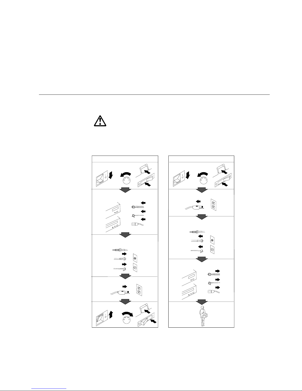
Safety Information
Turn everything OFF.
Attach signal cables to
receptacles.
First, remove power cord from
outlet.
To Disconnect
Turn device ON.
DANGER:
Turn everything OFF.
To Connect
Remove signal cables from
receptacles.
Remove all cables from devices.
Attach power cord to outlet.
First, attach all cables to devices.
In the U.K., by law, the power
cord must be disconnected after the
telephone line cable.
2
In the U.K., by law, the telephone
cable must be connected after the
power cord.
12
1
Electrical current from power, telephone, and communication
cables is hazardous. To avoid shock hazard, connect and
disconnect cables as shown below when installing, moving or
opening the covers of this product or attached devices. The
power cord must be used with a properly grounded outlet.
Copyright IBM Corp. 1995 vii
Page 10

About This Book
Pour deconnecter
Pour connecter
Branchez le cordon d’alimentation
sur la prise murale.
Mettez l’unité sous tension.
DANGER:
Débranchez d’abord le cordon
d’alimentation de la prise murale.
Déconnectez les câbles de signaux
des prises murales.
Déconnectez tous les câbles
de unités.
Mettez tout hors tension.
Mettez tout hors tension.
Le courant électrique provenant des câbles d’alimentation,
télephoniques et de transmission peut présenter un danger.
Pour éviter tout risque de choc électrique, connectez et
déconnectez ces câbles comme indiqué ci- dessous lorsque
vous installez ou déplacez ce matériel ou les unités connectées,
ou que vous soulevez un carter.*
Connectez les câbles de signaux
sur les prises murales.
Connectez d’abord tous les câbles
sur les unités.
*Le cordon d’alimentation doit être
branché sur un socle de prise de
courant correctement mis à la terre.
x PC Server 520 User's Handbook for PCI/EISA
Page 11

About This Book
Laser Compliance Statement
The PC Server 520 is a laser product. The drive has a label that
identifies its classification. The label, located on the drive, is shown
below.
CLASS 1 LASER PRODUCT
LASER KLASSE 1
LUOKAN 1 LASERLAITE
KLASS 1 LASER APPARAT
APPAREIL À LASER DE CLASSE 1
EN 60825
The PC Server 520 is certified in the U.S. to conform to the
requirements of the Department of Health and Human Services 21
Code of Federal Regulations (DHHS 21 CFR) Subchapter J for Class
1 laser products. Elsewhere, the drive is certified to conform to the
requirements of EN 60825.
CAUTION:
Do not open the drive; no user adjustments or serviceable parts
are inside.
Class 1 laser products are not considered to be hazardous. The PC
Server 520 has an internal Class 1 gallium-arsenide laser that is
nominally 0.14 milliwatts at 765 to 815 nanometers wavelength.
Safety Information xi
Page 12

About This Book
xii PC Server 520 User's Handbook for PCI/EISA
Page 13

About This Book
This book provides the instructions for completing your installation;
installing and removing server options; and configuring, modifying,
and troubleshooting your server. This book also provides
information to help you solve some of the simpler problems that
might occur. If you have not yet set up your server, refer to the
Setup sheet for instructions on unpacking and cabling the server.
See Chapter 2, “Installing Software” on page 21 for details about
installing an operating system and other software. Refer to the
User's Reference for more detailed information about the server's
features.
How This Book is Organized
Chapter 1, “Introducing the PC Server 520,” introduces and
describes the PC Server 520. This chapter also includes an overview
of the server's features and components. In addition, this chapter
contains instructions for starting the server and using the CD-ROM
drive.
Chapter 2, “Installing Software,” describes factors that you might
want to consider before installing hardware and software in your
server. This chapter also provides instructions for completing your
installation. This includes installing device drivers, installing an
operating system using some of the programs that are provided on
compact discs (CDs) in the IBM ServerGuide package, and installing
the PeerMaster LAN software that is required for models that come
with the PeerMaster adapter.
Chapter 3, “Configuring the Disk Array,” applies only to disk-array
models. This chapter provides instructions for configuring models
that come with a ServeRAID disk-array controller. These
instructions include step-by-step procedures for the tasks necessary
to configure, add, change, and delete one or more disk arrays. This
chapter also contains information about the disk-array adapter
configuration program, drive maintenance, and the RAID diagnostic
program.
Chapter 4, “Configuring the PeerMaster Adapter,” contains
instructions for configuring, cabling, and testing the PeerMaster
adapter.
Copyright IBM Corp. 1995, 1996 xiii
Page 14

Welcome and Thank You
Chapter 5, “Installing Options,” contains step-by-step instructions
for installing and removing hardware options, such as
memory-module kits, adapters, and internal drives. Instructions for
connecting external options are also included in this chapter.
Chapter 6, “Configuring Your Server,” contains instructions for
configuring your server. This chapter also provides instructions for
using various utility programs.
Chapter 7, “Solving Problems,” contains information to help you
solve simple problems that you might encounter with your server.
This chapter includes an overview of diagnostic tools, instructions
for testing the server, lists of error messages, and troubleshooting
charts. This chapter also contains information about checking the
server for damage, and resolving configuration conflicts.
Chapter 8, “Getting Help, Service, and Information,” contains
information to help you solve more complex problems that you
might encounter with your server. This chapter provides
instructions on how to obtain service and technical assistance for
your PC Server 520 and other IBM products that you might plan to
use. This chapter also contains information about other
publications, products, warranties, and services that IBM offers.
Also included are fax numbers, toll-free telephone numbers, and
access information for electronic bulletin boards, online services, and
the World Wide Web.
Appendix A, “Server Records,” provides a section to record and
update important information about your server, including the serial
numbers, key number, and device records (which contain
configuration information). Whenever you add options to your
server, be sure to update the information in this appendix.
Appendix B, “Notices,” contains product notices and trademarks.
If you find a term that you are not familiar with, refer to the
glossary located in the back of the User's Reference.
xiv PC Server 520 User's Handbook for PCI/EISA
Page 15

Welcome and Thank You
Notices Used in This Book
This book contains information notices that relate to a specific topic.
The notice definitions are as follows:
Notes
These notices provide important tips, guidance, or advice.
Attention
These notices indicate possible damage to programs, devices, or
data. An attention notice appears just before the instruction or
situation in which damage could occur.
Caution
These notices indicate situations that potentially can be
hazardous to you. A caution notice appears just before the
instruction or situation that could be hazardous.
About This Book xv
Page 16

Welcome and Thank You
Related Publications
In addition to this handbook, the following publications are
included with your server:
The Setup sheet contains the instructions for unpacking, setting
up, and cabling your server.
The User's Reference contains detailed information about the
advanced features of your server.
The PC Server Service and Support pamphlet contains important
information and phone numbers to call for different types of
support for your PC Server.
Included with the ServerGuide package is a publication that
describes the advantages of the IBM ServerGuide.
The IBM PC Servers Hardware Maintenance Manual Supplement is
available for purchase. It contains error codes, advanced diagnostic
procedures, and a parts catalog for most models. This manual is
intended for trained service technicians. (Diagnostic Diskettes are
not included.)
For a complete listing of publications available in the U.S. and
Puerto Rico, call 1-800-426-7282. In Canada, call Customer
Assistance at 1-800-465-1234. In all other countries, contact the IBM
support organization that services your area, your IBM marketing
representative, or your IBM reseller.
xvi PC Server 520 User's Handbook for PCI/EISA
Page 17

Welcome and Thank You
We appreciate your decision to purchase an IBM PC Server 520.
Your server offers speed, power, expandability, and compatibility
with various existing Network Operating Systems and application
programs.
The publications that come with your server are: the Setup sheet,
this User's Handbook, the User's Reference, and a PC Server Service and
Support pamphlet. The Setup sheet contains instructions to help you
set up your server. See “How This Book is Organized” on page ix
for a complete description of the User's Handbook. The User's
Reference contains detailed information about the advanced features
of your server. The PC Server Service and Support pamphlet contains
important information and phone numbers to call for different types
of support for your server. Review these publications thoroughly
before you install an operating system, additional software, or
optional hardware in your server.
Also included is the ServerGuide package, which contains several
CDs. These CDs contain operating systems, application programs,
utility programs, online documentation, and more. Refer to the
ServerGuide documentation that comes with ServerGuide for more
information.
The PC Server 520 also comes with IBM PC Server Startup Support,
which provides coverage during the first 90 days after installation.
IBM PC Server Startup Support is available to PC Server customers
at no additional charge. This comprehensive program enhances
IBM's support for setup, installation, configuration, and problem
determination. It provides assistance for popular network operating
systems and network adapters from IBM and other vendors. If you
need assistance, call IBM at 1-800-772-2227 in the U.S., or call IBM at
1-800-565-3344 in Canada. In all other countries, contact the IBM
support organization that services your area, your IBM marketing
representative, or your IBM reseller.
Copyright IBM Corp. 1995, 1996 xvii
Page 18

Welcome and Thank You
xviii PC Server 520 User's Handbook for PCI/EISA
Page 19

Chapter 1. Introducing the PC Server 520
Your IBM PC Server 520 has an Intel Pentium microprocessor and
symmetric multiprocessing (SMP) upgradability, along with a
peripheral component interconnect (PCI) advanced bus, large
data-storage capacity, and improved system expandability. The
server supports SCSI devices with an IBM PC Server SCSI-2
Fast/Wide PCI Adapter or IBM PC ServeRAID Adapter, depending
on the model. This server is specifically designed by IBM to handle
heavy file-server applications or moderate database applications in
today's network environment. The super video graphics array
(SVGA) controller provides compatibility with a wide range of
various existing Network Operating Systems and application
programs.
As an open-architecture, industry-standard system, the PC Server
520 has been tested for compatibility with numerous IBM and
non-IBM adapters and devices. Rugged dependability is achieved
by incorporating various quality standards and design points, such
as stringent IBM systems assurance testing, and a cooling design
called FloThru. FloThru cooling helps keep internal electronic
components of the PC Server 520 running cool to improve reliability
and accommodate the full configurations necessary in today's LAN
environments.
Refer to the Setup sheet for instructions for setting up your server.
Be sure to read the publications that come with the IBM
ServerGuide package before you set up your server.
This chapter contains an overview of the server features and
components. In addition, this chapter describes how to start the
server and use the CD-ROM drive.
See Chapter 2, “Installing Software” on page 21 for details about
installing an operating system and other software. In addition, this
book describes how to configure and use the server, and how to
install and remove options. The troubleshooting information will
help you solve some of the simpler problems that might occur.
Appendix A, “Server Records” on page 369 provides a section for
you to record all the important information about your server.
Copyright IBM Corp. 1995, 1996 1
Page 20

Refer to the User's Reference for more detailed information about the
server features. That book also includes a glossary, warranty
information, and other important notices.
This chapter contains:
Features at a Glance
........................... 3
Controls and Status Indicators .................... 4
Input/Output Connectors . . . . . . . . . . . . . . . . . . . . . . . 6
Expansion Bays . . . . . . . . . . . . . . . . . . . . . . . . . . . . . 8
Before You Begin ............................ 9
Moving the Server ............................ 10
Starting the Server ............................ 11
Using the CD-ROM Drive ....................... 16
Getting Help on the World Wide Web ............... 18
IBM PC Server Startup Support .................... 19
2 PC Server 520 User's Handbook for PCI/EISA
Page 21

Features at a Glance
The features in your server vary according to the model that you purchased. The following is a
summary of the features that are available with the PC Server 520.
Microprocessor
Intel Pentium microprocessor with
16 KB of internal cache; clock rate
varies by model
A processor upgrade, which adds
another Pentium microprocessor,
is available for symmetric
multiprocessing
Cache Memory
512 KB of level-2 cache
Memory
Error Correcting Code on SIMM
(EOS), 70 ns
32 MB minimum, expandable to
256 MB
Amount of memory is model
dependent
Eight 72-pin, single-inline
memory-module (SIMM) sockets
Diskette Drives
Standard: One 3.5-inch, 1.44 MB
Optional (internal):
– 3.5-inch, 1.44 MB
– 3.5-inch, 2.88 MB
– 5.25-inch, 1.2 MB
Hard Disk Drives
Number of drives and drive
capacities are model dependent
Can support up to 20 hard disk
drives, 18 of them hot-swappable
CD-ROM Drive
Standard: SCSI-2 CD-ROM
Keyboard and Auxiliary Device
101-key keyboard
Mouse
Expansion Bays and Slots
Two PCI slots
Five combination EISA/ISA slots
One shared PCI/EISA slot
22 drive bays, 18 of them
hot-swap
Video
Super video graphics array
(SVGA) connector
Compatibility:
– Video graphics array (VGA)
– Color graphics adapter (CGA)
– Multicolor graphics array
(MCGA)
Security Features
Bolt-down capability
Door lock
Selectable drive-startup
Security cover (optional)
Supervisor and User passwords
Integrated Functions
LED usability support
Video connector
Two serial connectors
Parallel connector
Auxiliary device connector
Keyboard connector
Battery-backed clock and calendar
SCSI-2 Controller
IBM PC Server SCSI-2 Fast/Wide
PCI Adapter on non-disk-array
models
IBM PC ServeRAID Adapter on
disk-array models
Power Supply
434 watt with automatic range
voltage selection (115–230 V ac)
Built-in overload and surge
protection
Power supply upgrade expansion
option
– 220 watt automatic range
voltage selection add-on
– Built-in overload and surge
protection
IBM PC Server 780W Redundant
Power Option
– 780 watt with automatic
range voltage selection
(115–230 V ac)
– Built-in overload and surge
protection
Upgradable Power-On Self-Test
(POST) and Basic Input/Output
System (BIOS)
Upgradable electrically erasable
programmable read-only memory
(EEPROM) on the system board
POST/BIOS upgrades (when
available)
Chapter 1. Introducing the PC Server 520 3
Page 22

Controls and Status Indicators
Your server front panel contains one switch: Power On/Off. This
switch is illustrated below and is described in the following list.
Your server has two light-emitting diode (LED) indicators that show
the system status. The amber indicators highlight the alert
conditions; the green indicators confirm that the server is operating
properly. The two indicators on your server are Power OK and Hard
Disk Drive Activity. These indicators are illustrated below and are
described in the following list.
Power OK Indicator
Power On/Off Switch
Hard Disk Drive
Activity Indicator
4 PC Server 520 User's Handbook for PCI/EISA
Page 23

Power On/Off: Use this switch to turn your server on and off.
To turn on the server, press the Power On/Off switch momentarily,
and the Power OK indicator will illuminate in approximately one
second. The Power On/Off switch is located under a transparent
cover on the right side of the front of the server. Before you can
turn the server on or off, you must lift this cover to reach the switch.
To avoid accidentally pressing the Power On/Off switch after you
have turned the server on or off, return the transparent cover to its
original position.
Power OK: This green indicator shows that the server power
supply is working properly.
Hard Disk Drive Activity: This amber indicator shows the server
hard disk drive activity.
Chapter 1. Introducing the PC Server 520 5
Page 24
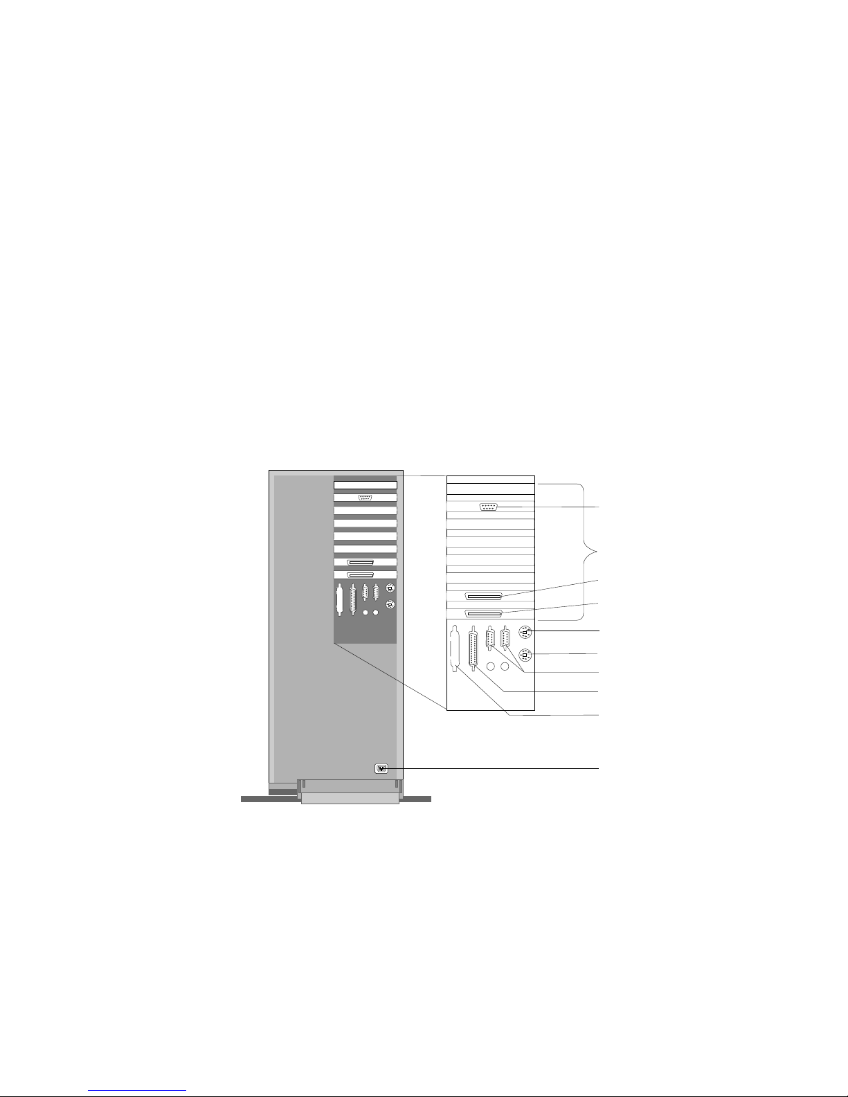
Input/Output Connectors
Input/Output Connectors
Power Connector
Monitor Connector
Serial Connectors
Parallel Connector
Expansion Slots
SCSI Connector
(Non-Disk-Array Models)
SCSI Connector
(Disk-Array Models)
SCSI Connector
Knockout
Keyboard Connector
Mouse Connector
Notes:
1. Some models come with a preinstalled ServeRAID
adapter in a PCI expansion slot.
2. Some models come with a preinstalled PeerMaster
adapter in a PCI expansion slot.
3. For pin assignments and other details about these
connectors, see the User's Reference.
6 PC Server 520 User's Handbook for PCI/EISA
Page 25

Input/Output Connectors
Power Connector: The power cable connects here.
Mouse Connector: The mouse cable connects here. This port also is
called an auxiliary-device or pointing-device port.
Keyboard Connector: The keyboard cable connects here.
Parallel Connector: One 25-pin parallel connector is provided. This
is where the signal cable for a parallel printer or other parallel
device connects to your server.
SCSI Connector Knockout: This knockout allows access to the
internal connector on a second SCSI-2 adapter.
Serial Connectors: Two 9-pin serial connectors (A and B) are
provided. The serial signal cable for a modem or other serial device
usually connects here. If you are using a 25-pin signal cable, you
need a 9-pin-to-25-pin adapter cable.
SCSI-2 Connector: For non-disk-array models, external small
computer system interface (SCSI) devices attach here. For disk-array
models, the SCSI-2 connector is located in the bottom PCI adapter
slot.
Monitor Connector: The monitor signal cable attaches to the
connector on this adapter.
Chapter 1. Introducing the PC Server 520 7
Page 26

Expansion Bays
Your server comes with one 3.5-inch, 1.44 MB diskette drive, a SCSI
CD-ROM drive, and a removable CD-ROM storage compartment.
(1 MB equals approximately 1000000 bytes.) The number of
preinstalled hard disk drives in your server varies according to the
model that you purchased.
CD-ROM Drive
Diskette Drive
Hard
Disk Drives
Open Bays
Open Bays
CD-ROM Drive: All models come with a SCSI-2 CD-ROM
drive.
Diskette Drive: The 3.5-inch, 1.44 MB diskette drive uses 1 MB
and 2 MB diskettes.
Open Bays: Your server has a special design that gives you the
flexibility to use up to 18 hot-swap, 3.5-inch hard disk drives.
There is additional open space in the top left bay for two more
diskette drives or an additional SCSI drive. For installation
instructions and information on the types of drives that you can
install in each bay, see Chapter 5, “Installing Options” on
page 153.
8 PC Server 520 User's Handbook for PCI/EISA
Page 27

Before You Begin
Hard Disk Drive: All models come with a SCSI-2 adapter to
support SCSI drives. The number, capacity, and location of the
hard disk drives vary, depending on your model.
Note: For the latest information on available options, contact your
IBM reseller or IBM marketing representative.
Before You Begin
Make sure you have an adequate number of properly grounded
electrical outlets for your server, monitor, and any other options
that you intend to install.
Place your server in a location that is dry. Rain or spilled
liquids might damage your server.
Leave about 51 mm (2 in.) of space around the front and rear of
your server to allow the server's cooling system to work
properly.
Have a supply of 1 MB and 2 MB, 3.5-inch diskettes available.
You will need these diskettes later, when you install your
operating system and backup your configuration and all
important data.
Have small, flat-blade and Phillips screwdrivers available.
If you have not already done so, perform the following tasks.
Instructions are located on a separate sheet that comes with your
server.
Unpack your server.
Remove the packing material.
If you are not installing any optional hardware at this time,
connect the cables and power cord.
After you complete these tasks, return here for further instructions.
Chapter 1. Introducing the PC Server 520 9
Page 28

Moving the Server
Moving the Server
CAUTION:
Due to the weight of the server, do not attempt to lift the server
by yourself. To avoid possible injury while moving or lifting the
server, ask another person to help you.
When the server is in the normal upright position, move it by lifting
up on the handle and rolling it forward or backward as shown.
(A roller is built into the rear of the server base.)
10 PC Server 520 User's Handbook for PCI/EISA
Page 29

Starting the Server
Starting the Server
1. Turn on your monitor and adjust the Brightness and Contrast
controls to the approximate midpoint.
You can readjust these controls and the monitor location for
personal viewing comfort after you turn on your server.
Note: The locations of the Power Switch and the Brightness and
Contrast controls on your monitor might be different
from those shown above.
2. Adjust the keyboard feet and position the keyboard for personal
typing comfort.
Chapter 1. Introducing the PC Server 520 11
Page 30

Starting the Server
3. Locate the keys; then, unlock and open the door (turn the key
90 degrees to the left).
Front Cover
Locked
Upper Door
Unlocked
Front Cover
Unlocked
12 PC Server 520 User's Handbook for PCI/EISA
Page 31

Starting the Server
4. If the diskette drive contains packing material or a diskette,
remove it from the drive.
Diskette
Eject
Button
CD-ROM TrayRelease Button
Manual TrayRelease
Opening
CD-ROM
Drive
Diskette
Drive
5. If the server is turned on, turn it off.
Note: The Power On/Off switch is located under a transparent
cover on the right side of the server. You must lift this
transparent cover to reach the Power On/Off switch.
6. If you installed any external devices, such as printers, plotters,
or modems, turn them on now.
Chapter 1. Introducing the PC Server 520 13
Page 32
Starting the Server
7. Turn on the server.
To turn on the server, press the Power On/Off switch
momentarily, and the Power OK indicator will illuminate. The
power-on self-test (POST) begins.
Power
On/Off
Button
Power OK Indicator
14 PC Server 520 User's Handbook for PCI/EISA
Page 33

Starting the Server
8. Check your monitor. The screen displays the IBM logo and a
number that represents the amount of available server memory.
The server beeps once to indicate that it is working properly.
Notes:
If you hear more than one beep, or no beep, check to
see if an error message appears. If an error message
appears, or if your screen is blank, see Chapter 7,
“Solving Problems” on page 299.
If your server stops running during testing or normal
operation, call for service. Describe the problem to
the service technician.
If no operating system is installed, a code of 1300
appears on the screen. Before you install an
operating system, be sure to start the ServerGuide
Main compact disc (CD) and review the README file
in the Start Here section. See “About ServerGuide”
on page 26 for additional information and
instructions.
Chapter 1. Introducing the PC Server 520 15
Page 34
Using the CD-ROM Drive
A SCSI-2 CD-ROM drive is a standard feature on all PC Server 520
models. To use the CD-ROM drive:
1. Have the main CD ready.
2. Press the CD-ROM tray-release button. The CD-ROM tray will
extend out approximately 25 mm (1 in.) from the server. Pull
the tray straight out until it stops.
Diskette
Eject
Button
CD-ROM TrayRelease Button
Manual TrayRelease
Opening
CD-ROM
Drive
Diskette
Drive
Note: If the CD-ROM tray does not extend out, insert the end
of a paper clip into the manual tray-release opening and
gently pull the tray open.
16 PC Server 520 User's Handbook for PCI/EISA
Page 35
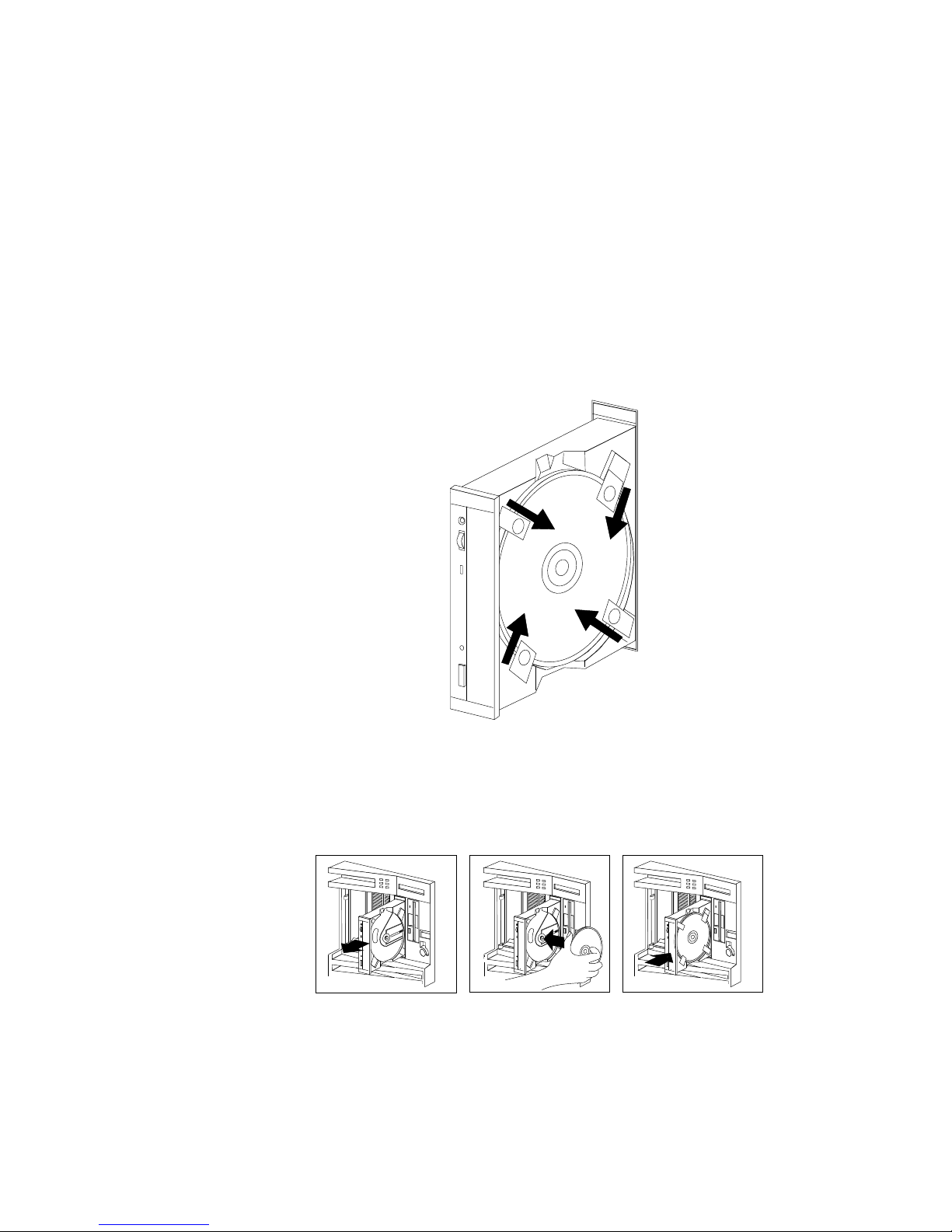
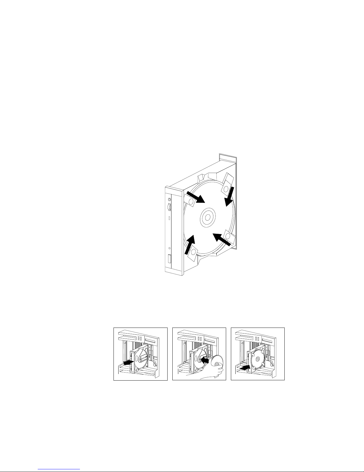
3. Locate the tabs in the corners of the tray.
4. With the label information facing right, center and hold the
ServerGuide Main CD on the tray as shown.
5. Insert a fingertip or a small, blunt object such as the tip of a pen
into the depression on each tab; then, slide the tabs over the CD.
6. Push the CD-ROM tray back into the server.
7. Insert the ServerGuide License Diskette into the diskette drive.
8. Press the Ctrl+Alt+Del key sequence to restart the server.
Chapter 1. Introducing the PC Server 520 17
Page 36

Getting Help on the World Wide Web
The ServerGuide logo screen appears, followed by a
language-selection screen.
9. Select a language; the Main Menu appears.
10. Select Start Here and review the information.
The README file in the Start Here section of the ServerGuide
Main CD contains important information about ServerGuide, the
operating systems, and device drivers. Be sure to review the
README file before you install your operating system.
Getting Help on the World Wide Web
You can access the latest information about configuration and
product compatibility on the World Wide Web. This information is
updated as new PC Server products are announced. The following
is a sample of the information available at
http://www.pc.ibm.com/servers/ on the World Wide Web.
Current updates to device drivers, flash BIOS, and other code.
Certification and compatibility information about Network
Operating Systems (NOS) and Operating Systems (OS).
A listing of products that have been tested for compatibility
with IBM PC Server.
For additional information, service, or assistance, see Chapter 8,
“Getting Help, Service, and Information” on page 359.
18 PC Server 520 User's Handbook for PCI/EISA
Page 37

IBM PC Server Startup Support
The IBM PC Server Startup Support program provides
comprehensive telephone assistance 24 hours a day, 7 days a week,
during the first 90 days after installation of your server, at no
additional charge.
IBM gives you direct access to trained specialists who can help you
set up, install, and configure your server.
*
Help is available for IBM and non-IBM network operating systems,
network interface adapters, and other optional peripherals. To
receive a list of the network products supported by the IBM PC
Server Startup Support program, call the IBM PC Company
Automated Fax System at 1-800-426-3395 in the U.S., or call
1-800-465-3299 in Canada, and ask for document number 16125. For
more information about this program, or for help with the
installation of your server:
In the U.S., call IBM at 1-800-772-2227
In Canada, call IBM at 1-800-565-3344
In all other countries, contact the IBM support organization that
services your area, your IBM marketing representative, or your
IBM reseller.
Note: For additional information, service, or assistance, see
Chapter 8, “Getting Help, Service, and Information” on
page 359.
*
Response time might vary depending on the number and nature of calls received.
Chapter 1. Introducing the PC Server 520
19
Page 38

20 PC Server 520 User's Handbook for PCI/EISA
Page 39

Chapter 2. Installing Software
Before you install software in your server, you must determine the
software, hardware, and operating system requirements for your
operating environment. Because some models come with special
adapters, you might need to use the configuration programs on an
adapter's configuration diskette, such as the ServeRAID
Configuration diskette, before you install an operating system and
other software.
This chapter describes the factors that you might want to consider
before selecting and installing an operating system and other
software in your server. This chapter also describes operating
system installation. You can install an operating system through
ServerGuide or a separately purchased, off-the-shelf operating
system.
This chapter also includes instructions for configuring the IBM
Ethernet Quad PeerMaster PCI Server Adapter that comes in some
models. Finally, this chapter contains a comprehensive checklist for
completing the installation.
At this time, you should have unpacked your server and attached
cables to it. (Refer to the Setup sheet for instructions.) Be sure to
read the publications that come with the IBM ServerGuide package
before you set up your server. That chapter also includes
instructions for using the CD-ROM drive.
Note: If you need service or assistance, see Chapter 8, “Getting
Help, Service, and Information” on page 359.
This chapter contains:
Software Considerations
. . . . . . . . . . . . . . . . . . . . . . . . 22
Installing an Operating System .................... 22
Before You Begin ........................... 23
OS/2 and Novell NetWare Installation .............. 24
OS/2 LAN Server 4.0 Fixpaks ................... 25
SCO OpenServer Installation .................... 25
Windows NT Installation ...................... 25
DOS Installation . . . . . . . . . . . . . . . . . . . . . . . . . . . 26
All Other Installations ........................ 26
About ServerGuide . . . . . . . . . . . . . . . . . . . . . . . . . . . 26
Starting the ServerGuide Main CD ................ 27
Copyright IBM Corp. 1995, 1996 21
Page 40

Installing an Operating System
Device Drivers . . . . . . . . . . . . . . . . . . . . . . . . . . . . . . 30
Network Adapter Device Drivers ................. 31
Hardware Device Drivers ...................... 32
Installing the PeerMaster LAN Software .............. 33
Installing PeerMaster Software for OS/2 ............. 34
Installing PeerMaster Software for Windows NT ........ 35
Installing PeerMaster Software for Novell NetWare ...... 36
Installing Device Drivers for SCO Open Server ......... 36
Using NetFinity with Your PeerMaster Adapter ........ 61
Arranging Your Workspace ...................... 69
Comfort . . . . . . . . . . . . . . . . . . . . . . . . . . . . . . . . 69
Glare and Lighting .......................... 70
Air Circulation . . . . . . . . . . . . . . . . . . . . . . . . . . . . 70
Electrical Outlets and Cable Lengths ............... 71
Installation Checklist . . . . . . . . . . . . . . . . . . . . . . . . . . 72
22 PC Server 520 User's Handbook for PCI/EISA
Page 41

Installing an Operating System
Software Considerations
IBM and other manufacturers of operating systems, network
programs, and application programs periodically make software
updates available. These updates provide enhancements and
corrections. To ensure that the software that you install functions
properly, contact the manufacturers to obtain the most current
updates.
If you intend to install an IBM operating system or network
programs, such as OS/2 for SMP or OS/2 LAN Server, you can
obtain the most current software updates from the IBM OS/2
Technical Support Center. These software updates are called
ServicePaks or corrective-service diskettes (CSDs). In the U.S., you
can call the IBM OS/2 Technical Support Center at 1-800-992-4777.
For the latest information about hardware device drivers and SMP
operating systems supported by your PC Server 520:
In the U.S., call IBM at 1-800-772-2227.
In Canada, call 1-800-565-3344.
In all other countries, contact the IBM support organization
that services your area, your IBM marketing representative,
or your IBM reseller.
To install your system management device drivers, follow the
instructions in the README file on the IBM PC Server Windows
NT Support Diskette that comes with the server.
Installing an Operating System
The IBM PC Server 520 combines powerful microprocessor
performance, large data-storage capacity, and system expandability,
ensuring that your server adapts to handle ever-changing operating
requirements. The operating system that you select allows you to
optimize some of the features in your server. Your server offers
dual-processor capability through a second processor socket, using
SMP technology. You can maximize the benefits of this technology,
Chapter 2. Installing Software 23
Page 42

Installing an Operating System
provided that you have an SMP-capable operating system, such as
one of the following, installed in your server:
OS/2 for SMP
Novell NetWare 4.1 for SMP
Microsoft Windows NT
Some security features are operating system-dependent, which
means that if you want to use them, you must install an operating
system that supports them. To find out whether an operating
system supports specific security features, see the documentation
that comes with the operating system.
Before You Begin
You can install an operating system from ServerGuide or from
separately purchased diskettes or CDs.
For all disk-array models, a ServeRAID Configuration diskette is
included. Before you install an operating system on a disk-array
model, use the configuration programs on the ServeRAID
Configuration diskette to view or change the existing disk-array
configuration. See Chapter 3, “Configuring the Disk Array” on
page 75 for detailed instructions; then, return here.
Before you install an operating system on a system with a
PeerMaster adapter, use the configuration programs on the
PeerMaster Adapter Option Diskette to view or change the
existing configuration. Refer to Chapter 4, “Configuring the
PeerMaster Adapter” on page 133 for detailed instructions; then,
return here.
If you have not already installed your options, do so now,
before you install your operating system. Installing your
options now enables ServerGuide to install the necessary device
drivers during the operating-system installation process. See
Chapter 5, “Installing Options” on page 153 for step-by-step
instructions; then, return here. Some options might require
device drivers that are not available on ServerGuide. In this
case, follow the installation instructions that come with the
option; then, return here.
24 PC Server 520 User's Handbook for PCI/EISA
Page 43

Installing an Operating System
If you are installing an operating system from the ServerGuide
CD, select Start Here and follow the instructions on the screen;
then, go to “Installation Checklist” on page 72.
If you are installing your own operating system:
1. Review “Software Considerations” on page 22 and
“Installing an Operating System” on page 22; then, return
here.
2. Follow the installation instructions that come with your
operating system; then, go to “Installation Checklist” on
page 72.
The following operating systems require special considerations.
OS/2
Novell NetWare
SCO OpenServer 5.0 (UNIX operating system)
Windows NT
These considerations are discussed in the following sections.
OS/2 and Novell NetWare Installation
For installation instructions for OS/2 or Novell NetWare, refer to
the README files in the Start Here section of the ServerGuide Main
CD.
If you have a disk-array model, refer to the README file on the
ServeRAID diskettes for installation instructions.
If you have an OS/2 2.11 SMP license and you want to install OS/2
2.11 SMP on your PC Server 520 without using ServerGuide, call
IBM HelpWare at one of the following numbers and request
authorized program analysis report (APAR) II08627.
In the U.S. and Puerto Rico, call 1-800-772-2227.
In Canada, call 1-800-565-3344.
In all other countries, contact your IBM reseller or IBM
marketing representative.
Chapter 2. Installing Software 25
Page 44

About ServerGuide
You must provide your OS/2 license information. The HelpWare
group will ship you a CD and installation diskettes.
OS/2 LAN Server 4.0 Fixpaks
There are several Fixpaks available for OS/2 LAN Server 4.0. These
Fixpaks are updated periodically to provide optimum support of
OS/2 LAN Server 4.0 functions across a wide range of hardware
configurations. To receive these updates in the U.S., call the IBM
OS/2 Technical Support Center at 1-800-992-4777. In all other
countries, contact the IBM support organization that services your
area, your IBM marketing representative, or your IBM reseller.
SCO OpenServer Installation
If you are installing Santa Cruz Operation (SCO) OpenServer 5.0 in
a disk-array model, you must have 3 GB for an HPFS partition. You
must obtain an additional device driver, ips. The Boot-Time
Loadable Driver is required for the ServeRAID Administration and
Monitoring program in your PC Server 520.
If you are installing an SCO operating system, you might need
updated device drivers for full compatibility with the latest
hardware used in IBM servers. Refer to the Start Here section on
the ServerGuide Main CD for information on how to obtain the
latest device drivers that are available from SCO. To install an SCO
operating system, follow the installation instructions that come with
the SCO operating system.
Windows NT Installation
For installation instructions for Windows NT, refer to the README
files on the diskette that comes with your operating system and on
the ServeRAID diskette that comes with your server.
If you have a disk-array model, and more than one logical drive is
present in a single drive configuration, and you intend to install
Windows NT, install DOS on the first logical drive. Then, install
Windows NT.
26 PC Server 520 User's Handbook for PCI/EISA
Page 45

Starting ServerGuide
For installation instructions for Windows NT Version 3.5 or later,
refer to the README file on the ServeRAID Configuration diskette
that comes with your server.
DOS Installation
If you are installing DOS, refer to the README files on the
ServeRAID Configuration diskette.
All Other Installations
If you are installing other operating systems, such as UnixWare, use
the installation instructions that come with the operating system.
About ServerGuide
It is important that you read and understand the following
information, whether you choose to install an operating system that
is available in the ServerGuide package or you choose to install your
own operating system.
Note: The IBM ServerGuide package contains various
operating-system update programs, some of which are
designed specifically for the IBM PC Server 520. Some of
these updates might not be provided in existing, off-the-shelf
versions of the operating systems. For this reason, if you
intend to use one or more of the operating systems that are
provided in the ServerGuide package, you should use
ServerGuide for the installation.
You can install an operating system from ServerGuide, or you can
install your own operating system and still use many of the features
that are available on ServerGuide. (For example, you can install
NetFinity, which is a LAN systems-management program; run
demonstration programs; use the performance-tuning feature; and
do much more.) Take the time now to read the information that
comes with the ServerGuide package; then, return here.
The ServerGuide CDs contain SCSI and VGA device drivers that
will be installed automatically if you install one of the operating
systems from the ServerGuide CD package. However, if you choose
to install SVGA applications or your own operating system, you will
Chapter 2. Installing Software 27
Page 46

Starting ServerGuide
need to install the SCSI device drivers and the SVGA device drivers.
These device drivers are on the diskettes that come with the server.
Refer to the README files on the diskettes for installation
instructions.
For additional considerations regarding device drivers and operating
systems, be sure to read “Software Considerations” on page 22,
“Installing an Operating System” on page 22, and “Device Drivers”
on page 30.
Starting the ServerGuide Main CD
One of the easiest and most efficient ways to install an operating
system and take advantage of a wide variety of the latest software
for the network environment is to use ServerGuide.
To start the ServerGuide Main CD:
1. If you have not already done so, turn on the server (see
“Starting the Server” on page 11).
2. Locate the ServerGuide CD package and diskettes.
3. Have the main CD ready.
28 PC Server 520 User's Handbook for PCI/EISA
Page 47

Starting ServerGuide
4. Press the CD-ROM tray-release button. The CD-ROM tray will
extend out approximately 25 mm (1 in.) from the server. Pull
the tray straight out until it stops.
Diskette
Eject
Button
CD-ROM TrayRelease Button
Manual TrayRelease
Opening
CD-ROM
Drive
Diskette
Drive
Note: If the CD-ROM tray does not extend out, insert the end
of a paper clip into the manual tray-release opening and
gently pull the tray open.
Chapter 2. Installing Software 29
Page 48
Device Drivers
5. Locate the tabs in the corners of the tray.
6. With the label information facing right, center and hold the
ServerGuide Main CD on the tray as shown.
7. Insert a fingertip or a small, blunt object such as the tip of a pen
into the depression on each tab; then, slide the tabs over the CD.
8. Push the CD-ROM tray back into the server.
9. Insert the ServerGuide License Diskette into the diskette drive.
30 PC Server 520 User's Handbook for PCI/EISA
Page 49

Device Drivers
10. Press the Ctrl+Alt+Del key sequence to restart the server.
The ServerGuide logo screen appears, followed by a
language-selection screen.
11. Select a language; the Main Menu appears.
12. Select Start Here and review the information.
The README files in the Start Here section of the ServerGuide
Main CD contain important information about ServerGuide,
operating systems, and device drivers. Be sure to review the
README files before you install your operating system.
Note: After using ServerGuide, verify that the date and time are
correct. Update these values if necessary.
Device Drivers
Device drivers are programs designed to support a specific type of
hardware device. They provide instructions that enable the
computer to interact with the device, or to take advantage of a
device's special feature. Not all devices require device drivers.
However, the RAID adapter and the PeerMaster adapter require the
installation of device drivers.
If you have a non-disk-array model, your IBM PC Server SCSI-2
Fast/Wide PCI Adapter Support Package contains device-driver files
that must be installed when you use OS/2, Novell NetWare,
Windows NT, and SCO UNIX. If you have a disk-array model,
your ServeRAID Device Driver/Administration and Monitoring
diskette contains device-driver files that must be installed when you
use OS/2, Novell NetWare, Windows NT, and SCO UNIX.
Note: See the README file in the IBM PC Server SCSI-2 Fast/Wide
PCI Adapter Support Package or on the Device
Driver/Administration and Monitoring diskette that comes
with your server for detailed instructions.
Chapter 2. Installing Software 31
Page 50

Device Drivers
Network Adapter Device Drivers
If you are using OS/2 LAN Server and you want to install a
network adapter in your PC Server 520 that does not appear as a
selectable choice in the ServerGuide window box, use the following
instructions:
1. Use the information and instructions provided with the
ServerGuide package to install OS/2 and OS/2 LAN Server.
Note: If there are other products provided on ServerGuide that
you want to install, install them now.
2. When the list of network adapters appears in the window box,
select None.
Note: The IBM Ethernet extended industry-standard
architecture (EISA) Adapter and the IBM 16/4 Busmaster
EISA Adapter, which appear on the ServerGuide device
driver installation menus, are not supported in the IBM
PC Server 520. However, the IBM PC Server 520 does
support the IBM Auto LANStreamer PCI Adapter, which
is a replacement product.
3. When the installation has completed, restart the server.
4. Press Enter to bypass the BIND error messages.
Note: If you installed NetFinity, a driver could not be found
message might appear. Select OK to continue.
5. After the operating system loads, access MPTS (for OS/2 LAN
Server 4.0) or LAPS (for OS/2 LAN Server 3.0) and configure
your server with the appropriate network adapter device driver.
Note:
MPTS = Multiple Protocol Transport Services
LAPS = LAN Adapter Protocol Support
6. Go to the operating system prompt, then type:
COPY E:\GO4.CMD C:\
7. Press Enter.
32 PC Server 520 User's Handbook for PCI/EISA
Page 51

Installing PeerMaster LAN Software
8. At the operating system prompt, type:
COPY E:\RESTART2.CMD C:\
9. Press Enter.
10. Perform a Shutdown of your server.
11. Restart your server. This will enable OS/2 LAN Server to
install with the device driver configuration that you selected in
step 5 on page 31.
Note: All of the products that you selected during the initial
installation will be reinstalled.
Hardware Device Drivers
For the latest information about hardware device drivers for the
IBM PC Server 520, OS/2 for SMP 2.11, and OS/2 LAN Server 4.0:
In the U.S. and Puerto Rico, call IBM at 1-800-772-2227
In Canada, call IBM at 1-800-565-3344
In all other countries, contact the IBM support organization that
services your area, your IBM marketing representative, or your
IBM reseller.
Note: In the United States and Canada, service is available toll-free,
24 hours a day, 7 days a week.
Chapter 2. Installing Software 33
Page 52

Installing PeerMaster LAN Software
Installing the PeerMaster LAN Software
Some PC Server 520 models come with an IBM Ethernet Quad
PeerMaster PCI Server Adapter (hereafter referred to as the
PeerMaster adapter) installed as a standard feature. This section
contains instructions for installing the PeerMaster LAN software
provided on the IBM PeerMaster Server Adapter Option Diskette
(hereafter referred to as the PeerMaster Option Diskette) that comes
with your server.
Before installing the LAN software, be sure your PeerMaster adapter
is configured, functional, and properly cabled to your network. (For
more information, see Chapter 4, “Configuring the PeerMaster
Adapter” on page 133.)
Note: You must install your network operating system before you
can install the PeerMaster LAN software.
To install and configure the PeerMaster LAN software:
For the latest version of the PeerMaster adapter diskette image file,
check the IBM bulletin board service (BBS), the IBM Personal
Computer Web site, or the IBM Personal Computer FTP site. Search
on the keyword PeerMaster to locate the file. Compare the file date
to your diskette date, to determine the latest version level.
The IBM BBS telephone number is: (919) 517-0001
The IBM Personal Computer Web site URL address is:
http:/www.pc.ibm.com/
The IBM Personal Computer FTP site address is: ftp.pc.ibm.com
If you have: Go to:
IBM OS/2 LAN Server Version 3x
or Version 4x
“Installing PeerMaster Software for
OS/2.”
Microsoft Windows NT Version 3.51 “Installing PeerMaster Software for
Windows NT” on page 35.
Novell NetWare Version 3.1x
or Version 4.x
“Installing PeerMaster Software for
Novell NetWare” on page 36.
SCO Open Server Enterprise
Version 3.x
“Installing Device Drivers for SCO
Open Server” on page 36.
34 PC Server 520 User's Handbook for PCI/EISA
Page 53

Installing PeerMaster LAN Software
Use “anonymous” as the user name and your e-mail address as
the password.
Installing PeerMaster Software for OS/2
Before continuing, be sure you have properly completed the
hardware installation of your PeerMaster adapter.
The installation instructions and device drivers for IBM OS/2 LAN
Server Version 3x or 4x are provided on the The PeerMaster Server
Adapter Option Diskette that comes with your PeerMaster adapter
The files are located in the OS2 directory.
The OS2 directory includes:
A:\OS2\NDIS.TXT
(where A: is the primary drive where OS2 is installed)
The NDIS.TXT file contains installation instructions for the OS/2
LAN Server device driver. This file also contains all the files in the
OS/2 and NETFINITY/OS2 directories.
Be sure to print and read the NDIS.TXT file before you begin this
portion of the installation.
If you have the IBM NetFinity Services for OS/2 installed on your
server, or if you install these services later:
1. Follow the instructions in the NDIS.TXT file on the PeerMaster
Server Adapter Option Diskette for installing the PeerMaster
LAN software for OS/2 server.
2. Then, continue with “Using NetFinity with Your PeerMaster
Adapter” on page 61.
Chapter 2. Installing Software 35
Page 54

Installing PeerMaster LAN Software
Installing PeerMaster Software for Windows NT
Before continuing, be sure you have properly completed the
hardware installation of your PeerMaster adapters.
The installation instructions and device drivers for Microsoft
Windows NT Version 3.5x are provided on the PeerMaster Server
Adapter Option Diskette that comes with your PeerMaster adapter.
These files are located in the NT directory.
The NT directory includes:
A:\NT\README.TXT
(where A: is the primary drive)
The README.TXT file contains installation instructions for the
PeerMaster Program files for Microsoft Windows. This file also
contains a description of all the files in the NT directory.
Be sure to print the README.TXT file before you begin this portion
of the installation.
36 PC Server 520 User's Handbook for PCI/EISA
Page 55

Installing PeerMaster LAN Software
Installing PeerMaster Software for Novell NetWare
Before continuing, be sure you have completed the hardware
installation and configuration of your PeerMaster adapter.
This section contains instructions for installing and configuring the
Novell NetWare LAN software. For more information about Novell
NetWare, refer to the documentation that comes with the software.
Installing Device Drivers for SCO Open Server
Before continuing, be sure you have properly completed the
hardware installation of your PeerMaster adapter.
An adapter diskette image file containing a link layer interface (LLI)
driver is available for the SCO Open Server Enterprise Release 3.x
operating system. Search the IBM BBS or the IBM Personal
Computer Web site for the keyword PeerMaster to locate the file.
The file is compressed in the Z format. It can be downloaded to a
DOS or OS/2 system and written to a DOS diskette, or downloaded
to a UNIX system. Copy the file to the server hard disk and expand
it using the UNIX UNCOMPRESS command. Use the UNIX DD
command to create a UNIX diskette containing the drivers. For
detailed instructions, configuration information, and usage
information, review the SCO driver README file.
Installation Overview
The following list provides the basic flow of the LAN software
installation process. The details required to install the software
begin with “Precautions, Limitations, and Guidelines” on page 38.
Note: The software supplied with the PeerMaster adapter enables
multiple physical LAN segments to be registered with Novell
NetWare as a single VNET.
1. Review “Precautions, Limitations, and Guidelines” on page 38
for specific Novell NetWare information.
2. Copy the LAN software onto your server hard disk. Install the
files for the PeerMaster adapter onto the DOS partition of your
server by copying them from the PeerMaster Server Adapter
Option Diskette. “Installing Network Device Drivers” on
page 39 guides you through this process.
Chapter 2. Installing Software 37
Page 56

Installing PeerMaster LAN Software
3. Start the server and activate the Novell NetWare operating
system at this time. “Starting Novell NetWare” on page 39
guides you through this process.
4. Load the PeerMaster adapter device drivers. Two device drivers
are provided for the PeerMaster adapter. MXPCI4BT.LAN is the
LAN device driver for the PeerMaster adapter. This device
driver enables the PeerMaster adapter to perform traditional
network functions. The other device driver, VNET.LAN, is the
virtual network device driver. This device driver enables the
PeerMaster adapter to operate in VNET Switch mode. “Loading
the Network Device Drivers” on page 40 and “Sample
AUTOEXEC.NCF Files” on page 53 guide you through this
process.
5. Update the Novell NetWare system files. The PeerMaster
adapter is shipped with the latest versions of several Novell
NetWare loadable module (NLM) files. These NLM files are
required for the proper operation of the PeerMaster adapter
under various versions of Novell NetWare. Copy these files
directly onto the Novell NetWare partition of your server.
“Updating Novell NetWare System Files” on page 46 guides
you through this process.
6. Modify the AUTOEXEC.NCF file, if desired. Update your
server startup configuration files to enable automatic loading of
your newly installed PeerMaster adapter. “Loading the
Network Device Drivers” on page 40 and “Sample
AUTOEXEC.NCF Files” on page 53 guide you through this
process.
38 PC Server 520 User's Handbook for PCI/EISA
Page 57

Installing PeerMaster LAN Software
Precautions, Limitations, and Guidelines
Review this section before you begin the installation and
configuration of the Novell NetWare device drivers.
All ports within a VNET must be configured to the same frame
type.
To support multiple frame types, you can load VNET.LAN
multiple times. When this is done, each instance of VNET.LAN
must be bound to a different network number and include the
identical grouping of the PeerMaster adapters.
You must configure a single PeerMaster adapter to operate
exclusively either as a VNET switch or as a traditional adapter.
Both modes cannot be supported simultaneously by a single
PeerMaster adapter.
Frame types loaded for VNET.LAN must be loaded for
MXPCI4BT.LAN. Examples of frame types include the IEEE
802.2 and 802.3 format as well as the Ethernet II and Ethernet
SNAP.
A newly loaded instance of VNET.LAN assumes control of all
currently active ports on each PeerMaster adapter included in
the VNET. A port is considered active after MXPCI4BT.LAN is
successfully loaded with the slot parameter value equal to the
number for that port.
To include previously inactive ports in an existing VNET, it is
necessary to unload VNET.LAN, activate additional ports, and
then reload VNET.LAN. Thus, it is best to activate all ports of a
PeerMaster adapter before loading VNET.LAN.
Chapter 2. Installing Software 39
Page 58

Installing PeerMaster LAN Software
Installing Network Device Drivers
To install the network device drivers, create a subdirectory using the
DOS command. In the following examples we are using the
subdirectory name NETWARE.
1. Insert the PeerMaster Server Adapter Option Diskette into an
available diskette drive and change to the Novell NetWare
device driver directory, for example:
CD A:\NETWARE
2. Create a subdirectory on a DOS partition of your server hard
disk, for example:
C:\NETWARE
3. Copy the contents of the device driver directory on the
PeerMaster Server Adapter Option Diskette to the target
directory, for example:
COPY A:\NETWARE\. C:\NETWARE\.
The directory on the PeerMaster Server Adapter Option Diskette
contains the open data-link interface (ODI) device drivers for
your PeerMaster adapter, the latest versions of various Novell
NetWare NLM files, and several sample AUTOEXEC.NCF files.
Starting Novell NetWare
To start Novell NetWare:
1. Start your server and enter the command to start the Novell
NetWare server software. If your server is running Novell
NetWare Version 3.11, manually load the system file,
LSLENH.NLM.
2. Load the file from the DOS drive and directory into where the
device drivers from the PeerMaster Server Adapter Option
Diskette were copied, for example:
:LOAD C:\PATH\LSLENH
(where C: is the primary drive and PATH is
the directory)
The power-on self-test (POST) results are displayed at device driver
load time. POST failures typically indicate an installation or
40 PC Server 520 User's Handbook for PCI/EISA
Page 59

Installing PeerMaster LAN Software
hardware problem with the PeerMaster adapter. For more
information on POST errors, see “PeerMaster Adapter Screen
Messages” on page 330.
Loading the Network Device Drivers
Your PeerMaster adapter comes with two network device drivers:
MXPCI4BT.LAN: This is the base device driver for using your
PeerMaster adapter. Once loaded and bound to a protocol, this
device driver enables your PeerMaster adapter to deliver the
functions associated with traditional network adapters.
VNET.LAN: This device driver enables several ports to be
bound to a protocol, such as internetwork packet exchange
(IPX), as a single VNET. VNETs enable PeerMaster adapters to
provide high-performance Ethernet switching functions
transparently under Novell NetWare.
It is necessary to understand pseudo slot numbers to load PeerMaster
device drivers. Traditional Novell NetWare device drivers use
expansion-slot numbers to associate specific LAN segments with
device-driver instances. PeerMaster adapters, however, provide
multiple LAN segments per expansion slot. For this reason, pseudo
slot numbers are used to uniquely identify each of the four ports on
a PeerMaster adapter. Pseudo slot numbers are two-digit, decimal
numbers, xy, where x is the unique BIOS or Flash slot number
assigned to the target PeerMaster adapter and y is the PeerMaster
adapter port number being configured. For example, a pseudo slot
number of 23 represents port 3 of the PeerMaster adapter
configured as slot number 2.
Most Significant Digit = Slot Number
(Slot 1, 2, 3, ..., 8)
The configured slot number is the number that you assigned to the
PeerMaster adapter. See “Using the PeerMaster Setup Utility
Program” on page 143 for more information.
Least Significant Digit = Port Number
(Port 1, 2, 3, 4)
Chapter 2. Installing Software 41
Page 60

Installing PeerMaster LAN Software
The Port Number refers to one of the four Ethernet ports on the
PeerMaster adapter.
You can specify unique configuration information for each instance
of the device driver by entering keywords on the command line.
The following sections provide descriptions of the keywords that
each device driver supports.
Keywords Supported Only by MXPCI4BT.LAN
SLOT This keyword is used to specify the port associated
with the device driver instance being loaded. Slot
values are expressed as pseudo slot numbers. The
following example illustrates the use of the SLOT
keyword.
SLOT=SLOT21
RXCOUNT This keyword is used to specify the amount of
resources allocated for reception from the PeerMaster
adapter. For more information on this keyword, see
“Adjusting Transmit and Receive Resources” on
page 59.
Keywords Supported Only by VNET.LAN
in, where n can be any number 1 through 8.
This keyword is used to indicate that the PeerMaster
adapter configured as slot n is to be included in the
VNET.
Keywords Supported by Both MXPCI4BT.LAN and VNET.LAN
NAME This keyword is used to associate a unique name with
a device-driver name for each instance as it is loaded.
The device-driver name can be used later to uniquely
bind the device driver instance to a protocol. For more
information on this parameter, refer to the
documentation that comes with your version of Novell
NetWare. The following example illustrates the use of
the NAME keyword.
NAME=SLOT21
42 PC Server 520 User's Handbook for PCI/EISA
Page 61

Installing PeerMaster LAN Software
FRAME This keyword is used to load a frame type for the
device driver instance being loaded. For more
information on this parameter, refer to the
documentation that comes with your version of Novell
NetWare. The following example illustrates the use of
the FRAME keyword.
FRAME=ETHERNET_82.2
NODE This keyword is used to override the factory-provided
MAC address present on your PeerMaster adapter.
When specified for MXPCI4BT.LAN, this keyword
overrides the factory-provided address. When
specified for VNET.LAN, this keyword overrides both
factory-provided and MXPCI4BT.LAN-specified node
addresses. The specified address must not be a group
address. The following example illustrates the use of
the NODE keyword.
NODE=123456
AGE This keyword is used to adjust the length of the aging
timeout used by the device driver and microcode to
purge unused entries from the address learning table
used by the packet switching function. For more
information on this keyword, see “Adjusting the Aging
Timer” on page 58.
TXCOUNT This keyword is used to specify the amount of
resources allocated for transmission to the PeerMaster
adapter. For more information on this keyword, see
“Adjusting Transmit and Receive Resources” on
page 59.
Chapter 2. Installing Software 43
Page 62

Installing PeerMaster LAN Software
Loading Procedure for PeerMaster Adapter Device Drivers
The manner in which the PeerMaster adapter device drivers are
loaded and configured defines the operational characteristics of the
PeerMaster adapter. You must take special care to properly load
and configure the device drivers.
This section provides three examples of the load process. The first
example illustrates the device driver loading procedure to configure
a PeerMaster adapter to operate in the traditional adapter mode. The
second example illustrates the procedure to configure a PeerMaster
adapter to operate in the VNET switch mode. The third example
illustrates the procedure to configure multiple PeerMaster adapters
to operate in a combined traditional adapter and VNET switch mode.
Loading Procedure for Traditional Adapter Mode
Each PeerMaster port must be registered as a separate network
segment to operate as a traditional network adapter. In this mode,
the protocol treats each PeerMaster port as a separate PeerMaster
adapter.
When loading the device drivers, use pseudo slot numbers in place
of physical slot numbers. In all other respects, load device drivers
for PeerMaster adapters in the same manner as device drivers for
traditional, single-port adapters. If the SLOT keyword is not used
on a load command, the device driver presents a list of available
pseudo slot numbers. Pseudo slot numbers that have already been
used will not be included. The following example is a typical load
command, assuming the device drivers are in the C:\NETWARE
directory.
:LOAD C:\NETWARE\MXPCI4BT.LAN SLOT=21
This command will cause Novell NetWare to load the device driver
for port 1 of the PeerMaster adapter that is configured as slot
number 2.
For each PeerMaster adapter, the base driver MXPCI4BT.LAN can
issue a maximum of four load commands per frame type. Novell
NetWare loads the default frame type for each device driver
instance unless the FRAME keyword is used to request a specific
44 PC Server 520 User's Handbook for PCI/EISA
Page 63

Installing PeerMaster LAN Software
frame type. The PeerMaster adapter comes configured with four
unique Ethernet MAC addresses. Thus, you do not need to use the
NODE keyword to create unique addresses for each port. You can,
however, override the factory-provided MAC address using the
NODE keyword.
Each time the load command is issued, Novell NetWare creates a
unique instance of the LAN device driver. You can use the NAME
keyword to bind a unique name to each instance of the device
driver. You can use this unique name with each device driver when
binding a specific instance of the device driver network protocol.
The following example illustrates use of the NAME keyword:
:LOAD C:\PATH\MXPCI4BT.LAN SLOT=21 NAME=SLOT21
:LOAD C:\PATH\MXPCI4BT.LAN SLOT=22 NAME=SLOT22
:LOAD C:\PATH\MXPCI4BT.LAN SLOT=23 NAME=SLOT23
:LOAD C:\PATH\MXPCI4BT.LAN SLOT=24 NAME=SLOT24
(where C: is the primary drive and PATH is the directory)
These commands cause Novell NetWare to load one instance of the
LAN device driver for each port of the PeerMaster adapter that is
configured as slot number 2. The NAME keyword associates each
device driver instance with a unique name (such as slot21, slot22,
and so forth).
In the traditional adapter mode, you must bind each device driver
instance to a network protocol using a unique network number.
The unique device driver names established using the NAME
keyword bind each device driver instance to a protocol. The
following example illustrates the bind process:
:BIND IPX SLOT21 NET=21
:BIND IPX SLOT22 NET=22
:BIND IPX SLOT23 NET=23
:BIND IPX SLOT24 NET=24
When you issue the load command, the NAME keyword is optional.
Alternatively, you can specify the actual device driver name
(MXPCI4BT.LAN) in the bind command. The bind command
presents you with the list of device driver instances to choose from
if a specific instance is not specified. Unique device driver names
Chapter 2. Installing Software 45
Page 64

Installing PeerMaster LAN Software
enable the bind process to occur without manual intervention. You
can automate the binding process by adding these statements to the
AUTOEXEC.NCF file.
The process for loading multiple PeerMaster adapters is identical to
the process for loading a single PeerMaster adapter. Load
successive PeerMaster adapters in the same manner as the first, with
the exception that the Most Significant Digit of the pseudo slot
number is the expansion slot number of the adapter being loaded.
Loading Procedure for VNET Switch Mode
This section describes the loading procedure for VNET switch mode.
1. Load the PeerMaster adapter device driver once for each port,
using the following commands.
:LOAD C:\PATH\MXPCI4BT.LAN SLOT=21
:LOAD C:\PATH\MXPCI4BT.LAN SLOT=22
:LOAD C:\PATH\MXPCI4BT.LAN SLOT=23
:LOAD C:\PATH\MXPCI4BT.LAN SLOT=24
(where C: is the primary drive and PATH is the directory)
2. Load the VNET.LAN device driver using the following
command.
:LOAD C:\PATH\VNET.LAN
(where C: is the primary drive and PATH is the directory)
3. Bind all active ports to the protocol using a common network
number, such as:
:BIND IPX VNET NET=2
You can load multiple instances of VNET.LAN to create multiple
VNETs. The command line syntax for loading multiple VNETs is
described in “Sample AUTOEXEC.NCF Files” on page 53.
Frame types, other than the default frame type, specified when
loading MXPCI4BT.LAN must also be specified when loading
VNET.LAN. The VNET.LAN load command will fail if the proper
frame types are not specified. The following example shows how to
create a VNET that supports multiple frame types.
46 PC Server 520 User's Handbook for PCI/EISA
Page 65

Installing PeerMaster LAN Software
:LOAD C:\PATH\MXPCI4BT.LAN SLOT=21 FRAME=ETHERNET_II
:LOAD C:\PATH\MXPCI4BT.LAN SLOT=22 FRAME=ETHERNET_II
:LOAD C:\PATH\MXPCI4BT.LAN SLOT=23 FRAME=ETHERNET_II
:LOAD C:\PATH\MXPCI4BT.LAN SLOT=24 FRAME=ETHERNET_II
:LOAD C:\PATH\MXPCI4BT.LAN SLOT=21 FRAME=ETHERNET_82.2
:LOAD C:\PATH\MXPCI4BT.LAN SLOT=22 FRAME=ETHERNET_82.2
:LOAD C:\PATH\MXPCI4BT.LAN SLOT=23 FRAME=ETHERNET_82.2
:LOAD C:\PATH\MXPCI4BT.LAN SLOT=24 FRAME=ETHERNET_82.2
:LOAD C:\PATH\VNET.LAN FRAME=ETHERNET_II NAME=VNET2
:LOAD C:\PATH\VNET.LAN FRAME=ETHERNET_82.2 NAME=VNET3
(where C: is the primary drive and PATH is the directory)
:BIND IPX VNET2 NET=2
:BIND IPX VNET2 NET=3
Loading Combined VNETs and Traditional Networks
Various transmit and receive control blocks and buffers exist to
support the bus-master interface between the PeerMaster adapter
and the host-based device driver. The resources determine the
number of transmit and receive packets that can be enqueued by the
bus-master interface. Increase the number of these resources only if
you have determined that packets are being lost due to lack of
resources.
To determine if packets have been lost due to lack of resources,
view the custom statistics using MONITOR.NLM. See “Custom
Statistics for VNET.LAN” on page 48 for details. If you need to
modify the count of these resources, see “Adjusting Transmit and
Receive Resources” on page 59 for details.
Specific instructions on how to create combined networks are
provided in “Sample AUTOEXEC.NCF Files” on page 53.
Updating Novell NetWare System Files
Your PeerMaster adapter comes with the latest versions of several
Novell NetWare NLM files. These files include fixes required for
the proper operation of your PeerMaster adapter under various
versions of Novell NetWare. Copy these files directly into the
Novell NetWare partition of your server. The following table
indicates the system files to replace.
Chapter 2. Installing Software 47
Page 66

Installing PeerMaster LAN Software
To update the system files, do the following steps:
1. Insert the PeerMaster Server Adapter Option Diskette into the
diskette drive of a workstation attached to your server.
2. Compare the file dates of the NLM files on your PeerMaster
Server Adapter Option Diskette with the dates of the same files
located in the SYS:\SYSTEM directory of your server. If the
specified file does not already exist, or if it is an old version,
replace the file with the newer version provided on the
PeerMaster Server Adapter Option Diskette.
Note: To copy a file, you might require supervisor access to
your server. Some files might be restricted to read-only
access. You must alter the attributes of such files to
successfully overwrite them.
After you copy the system files to your server, you will no longer
have to manually load system files from your DOS partition.
Filename
Novell
NetWare 3.11
Novell
NetWare 3.12
Novell
NetWare
4.x
MONITOR.NLM replace
LSLENH.NLM replace
MSM.NLM replace
MSM31X.NLM replace replace
ETHERTSM.NLM replace replace
PATCHMAN.NLM replace
Unloading the Network Device Drivers
Using Novell NetWare, you can unload LAN device drivers after
they are loaded and operational. When both MXPCI4BT.LAN and
VNET.LAN are loaded, it is important to unload VNET.LAN first,
then unload MXPCI4BT.LAN. When you unload a device driver, all
ports controlled by that device driver will become unbound from
the protocol stack. Specific named instances of the device driver
may not be selectively unloaded.
48 PC Server 520 User's Handbook for PCI/EISA
Page 67

Installing PeerMaster LAN Software
Using Novell NetWare Monitor
The Novell NetWare MONITOR.NLM provides custom statistics for
VNET.LAN and MXPCI4BT.LAN.
Custom Statistics for VNET.LAN You can display custom
statistics for VNET.LAN using MONITOR.NLM. You can select a
specific instance of VNET.LAN when multiple instances are loaded.
A specific instance of VNET.LAN can be uniquely identified when
multiple instances are loaded by two parameters: slot number and
frame type. The following example shows how MONITOR.NLM
prompts you to select among three instances of VNET.LAN.
VNET SLOT=41 FRAME=ETHERNET_82.2
VNET SLOT=C FRAME=ETHERNET_82.3
VNET SLOT=C FRAME=ETHERNET_82.2
Note: Slot numbers do not correspond to either physical or pseudo
slot numbers. This is because a single instance of VNET.LAN
might include multiple physical PeerMaster adapters. For
this reason, VNET.LAN slot numbers are represented as bit
masks. To ensure that VNET.LAN slot numbers do not
conflict with physical slot numbers, the least significant eight
bits of the mask are always set to 0. The upper eight bits of
the mask–bits 8 through 15–represent the physical slots 1
through 8. The following table shows the relationship
between VNET.LAN slot numbers and physical slot numbers.
The VNET slot number of 4100 specifies an instance of VNET.LAN
that includes the PeerMaster adapters configured to slots 7 and 1.
The sample slot value of 0C00 specifies a VNET.LAN including the
PeerMaster adapters configured to slots 3 and 4. Note that multiple
instances of VNET.LAN include the PeerMaster adapters configured
VNET.LAN Slot Slot Number
100 1
200 2
400 3
800 4
1000 5
2000 6
4000 7
8000 8
Chapter 2. Installing Software
49
Page 68

Installing PeerMaster LAN Software
to slots 3 and 4. Instances of VNET.LAN with identical slot
numbers can be uniquely selected by their frame type.
The following list provides the custom statistics presented by
VNET.LAN for each PeerMaster adapter.
Learned Entry Discards
The number of Forwarding Database entries, which have been
or would have been learned, but have been discarded due to a
lack of space to store them in the Forwarding Database.
If this counter is increasing, it indicates that the Forwarding
Database is regularly becoming full. If this counter has a
significant value but is not presently increasing, it indicates that
the problem has been occurring but is not persistent.
Peer Packets Received
The number of packets sourced from other PeerMaster adapters
that have been received from the system bus interface by this
PeerMaster adapter.
A packet received from the system bus interface is counted only
if it is for a protocol being processed by the local switching
function.
Peer Packets Transmitted
The number of packets that were sent to other PeerMaster
adapters that have been transmitted to the system bus interface
by this PeerMaster adapter.
A packet transmitted on the system bus interface is counted
only if it is for a protocol being processed by the local switching
function.
50 PC Server 520 User's Handbook for PCI/EISA
Page 69

Installing PeerMaster LAN Software
Peer Packets Discarded
The number of valid packets begun by other PeerMaster
adapters and received from the system bus interface by this
adapter that were discarded by the following process.
Port n Packets Received
The number of packets that have been received from its segment
by port n (where n = 1, 2, 3, or 4).
A packet received by the port is counted only if it is for a
protocol being processed by the local switching function.
Port n Packets Transmitted
The number of packets that have been transmitted to its
segment by port n (where n = 1, 2, 3, or 4).
A packet transmitted to the port is counted only if it is for a
protocol being processed by the local switching function.
Port n Packets Discarded
The number of valid packets received from its segment by port
n (where n = 1, 2, 3, or 4) that were discarded by the
switch-forwarding process.
Chapter 2. Installing Software 51
Page 70

Installing PeerMaster LAN Software
Custom Statistics for MXPCI4BT.LAN
You can display custom statistics for MXPCI4BT.LAN using
MONITOR.NLM. You can select a specific instance of
MXPCI4BT.LAN when multiple instances are loaded by two
parameters: slot number and packet type. The following example
shows how MONITOR.NLM prompts you to select among multiple
instances of MXPCI4BT.
MXPCI4BT SLOT=15 FRAME=ETHERNET_82.2
MXPCI4BT SLOT=16 FRAME=ETHERNET_82.2
MXPCI4BT SLOT=17 FRAME=ETHERNET_82.2
MXPCI4BT SLOT=18 FRAME=ETHERNET_82.2
Slot numbers appear in hex format. Slot numbers specified when
loading the device driver, however, must be specified in decimal
format. Therefore, you must translate slot numbers from hex to
decimal when loading the device drivers. The preceding example
represents the device drivers loaded with decimal slot numbers 21,
22, 23, and 24. This corresponds to ports 1, 2, 3, and 4 on the
PeerMaster adapter installed in physical slot 2.
The following custom statistics are presented on a peer-port basis:
Bytes Received: The total number of bytes that the port
received from its segment.
Unicast Packets Received: The total number of unicast packets
that the port received from its segment.
Multicast Packets Received: The total number of multicast
packets that the port received from its segment.
Broadcast Packets Received: The total number of broadcast
packets that the port received from its segment.
Discarded Received Packets: The total number of incoming
packets that the port was unable to receive from its segment due
to lack of resources.
Receive Errors: The total number of damaged packets that the
port received from its segment.
Bytes Transmitted: The total number of bytes that the port
transmitted to its segment.
52 PC Server 520 User's Handbook for PCI/EISA
Page 71

Installing PeerMaster LAN Software
Unicast Packets Transmitted: The total number of unicast
packets that the port transmitted to its segment.
Multicast Packets Transmitted: The total number of multicast
packets that the port transmitted to its segment.
Broadcast Packets Transmitted: The total number of broadcast
packets that the port transmitted to its segment.
Discarded Transmitted Packets: The total number of packets
that the port was unable to transmit to its segment due to lack
of resources.
Transmit Packets: The total number of packets transmitted by
the port to its segment.
Bus Transfer Errors: The total number of transmission errors
that occurred when data was transferred between other
PeerMaster adapters, or between the host system and a
PeerMaster adapter.
Host Transfer Errors: The total number of transmission errors
that occurred when data was transferred between the host
system and a PeerMaster adapter.
Peer Receive Out of Resources: The total number of packets
that a PeerMaster adapter received from other PeerMaster
adapters that were discarded due to insufficient resources to
transmit the packet.
Peer Transmit Out of Resources: The total number of packets
sent to other PeerMaster adapters that were discarded due to
insufficient resources on the adapters.
Adapter Receive Out of Resources: The total number of packets
sent to the host system that were discarded due to insufficient
resources on the host system.
Adapter Transmit Out of Resources: The total number of
packets sourced by the host system that were discarded by a
PeerMaster adapter due to insufficient resources to transmit the
packets.
Microcode Version: The revision level of the operational
microcode on the PeerMaster adapter.
Chapter 2. Installing Software 53
Page 72

Installing PeerMaster LAN Software
Generic Statistics
When operating in VNET switch mode, PeerMaster adapters switch
receive packets, as needed, to other LAN segments. This creates
transmit and receive statistics that alter the traditional meaning of
various generic statistic counters. The following generic counters
have a unique interpretation in VNET switch mode operation.
Total Packets Sent: The total number of packet transmissions
requested by the host open data-link interface (ODI) device
driver.
Total Packets Received: The total number of packets received
by the host ODI device driver.
Total Send OK Byte Count (Low or High): The total number of
bytes sent by the host ODI device driver.
Total Receive OK Byte Count (Low or High): The total number
of bytes received by the host ODI device driver.
All Ethernet-Specific Statistical Counters: This includes all
Ethernet-specific statistics, such as collisions, transmit status,
and receive status. These counters contain the sum of all
transmit and receive statistics resulting from both the host ODI
device driver and VNET switch activities. Thus, it is possible to
observe a value of zero for “Total Packets Sent” at the same
time as a nonzero value for a transmit statistic, such as “Send
OK Single Collision Count.” This combination of statistics
indicates that no packets were transmitted through the host
device driver, and that a nonzero number of VNET switch
packets for the specified port experienced single collisions.
Sample AUTOEXEC.NCF Files
You must add the following command line to your
AUTOEXEC.NCF file for Novell NetWare Version 3.11:
:LOAD C:\PATH\LSLENH
(where C: is the primary drive and PATH is the directory)
The following AUTOEXEC.NCF files provide information for servers
that have one, two, or three PeerMaster adapters installed.
54 PC Server 520 User's Handbook for PCI/EISA
Page 73

Installing PeerMaster LAN Software
One PeerMaster Adapter: Adding the following commands to
your AUTOEXEC.NCF file will cause your PeerMaster adapter to
operate in the traditional adapter mode. In this mode, each port is
bound to the protocol stack with a different network number. The
PeerMaster adapter will not be able to switch packets between
segments. Cross-segment traffic, if any, must be routed by a server
microprocessor.
:LOAD C:\PATH\MXPCI4BT.LAN SLOT=21 NAME=SLOT21
:LOAD C:\PATH\MXPCI4BT.LAN SLOT=22 NAME=SLOT22
:LOAD C:\PATH\MXPCI4BT.LAN SLOT=23 NAME=SLOT23
:LOAD C:\PATH\MXPCI4BT.LAN SLOT=24 NAME=SLOT24
(where C: is the primary drive and PATH is the directory)
:BIND IPX SLOT21 NET=21
:BIND IPX SLOT22 NET=22
:BIND IPX SLOT23 NET=23
:BIND IPX SLOT24 NET=24
Two PeerMaster Adapters: Adding the following commands to
your AUTOEXEC.NCF file will cause your PeerMaster adapters to
operate in the VNET switch mode. In this mode, all ports are
bound to the protocol stack with the same network number. The
PeerMaster adapter can switch packets between segments in this
mode.
:LOAD C:\PATH\MXPCI4BT.LAN SLOT=11
:LOAD C:\PATH\MXPCI4BT.LAN SLOT=12
:LOAD C:\PATH\MXPCI4BT.LAN SLOT=13
:LOAD C:\PATH\MXPCI4BT.LAN SLOT=14
:LOAD C:\PATH\MXPCI4BT.LAN SLOT=21
:LOAD C:\PATH\MXPCI4BT.LAN SLOT=22
:LOAD C:\PATH\MXPCI4BT.LAN SLOT=23
:LOAD C:\PATH\MXPCI4BT.LAN SLOT=24
(where C: is the primary drive and PATH is the directory)
Chapter 2. Installing Software 55
Page 74

Installing PeerMaster LAN Software
Create a VNET that globally includes all ports (no slots are
specifically included)
:LOAD C:\PATH\VNET.LAN
:BIND IPX VNET NET=2
(where C: is the primary drive and PATH is the directory)
Three PeerMaster Adapters - Example 1: Adding the following
commands to your AUTOEXEC.NCF file will cause your PeerMaster
adapter to form a combined network that is composed of an
8-segment VNET and four traditional networks. Cross-segment
traffic within the 8 segments of the VNET is switched by the
PeerMaster adapters. Cross-segment traffic from the VNET to a
traditional network, or between traditional network segments, is
routed internally by the server.
You can load the VNET.LAN device driver multiple times to create
multiple VNETs. The keywords to include a specific PeerMaster
adapter into a VNET are i1, i2, ... i8. The keyword i1 indicates a
request to include the PeerMaster adapter in expansion slot 1 into
the VNET being formed, i2 indicates the PeerMaster adapter in slot
2, and so forth.
The following example shows a server with three PeerMaster
adapters installed in expansion slots 1, 2, and 3.
:LOAD C:\PATH\MXPCI4BT.LAN SLOT=11
:LOAD C:\PATH\MXPCI4BT.LAN SLOT=12
:LOAD C:\PATH\MXPCI4BT.LAN SLOT=13
:LOAD C:\PATH\MXPCI4BT.LAN SLOT=14
:LOAD C:\PATH\MXPCI4BT.LAN SLOT=21 NAME=SLOT21
:LOAD C:\PATH\MXPCI4BT.LAN SLOT=22 NAME=SLOT22
:LOAD C:\PATH\MXPCI4BT.LAN SLOT=23 NAME=SLOT23
:LOAD C:\PATH\MXPCI4BT.LAN SLOT=24 NAME=SLOT24
:LOAD C:\PATH\MXPCI4BT.LAN SLOT=31
:LOAD C:\PATH\MXPCI4BT.LAN SLOT=32
:LOAD C:\PATH\MXPCI4BT.LAN SLOT=33
:LOAD C:\PATH\MXPCI4BT.LAN SLOT=34
(where C: is the primary drive and PATH is the directory)
56 PC Server 520 User's Handbook for PCI/EISA
Page 75

Installing PeerMaster LAN Software
Create four traditional networks
:BIND IPX SLOT21 NET=21
:BIND IPX SLOT22 NET=22
:BIND IPX SLOT23 NET=23
:BIND IPX SLOT24 NET=24
Create an eight-segment VNET consisting of adapters 1 and 3. Use
the i1 and i3 keywords to include adapters 1 and 3 into the VNET.
:LOAD C:VNET.LAN i1 i3
:BIND IPX VNET NET=2
(where C: is the primary drive)
In the preceding example, the PeerMaster adapters in slots 1 and 3
create an 8-segment VNET and are configured as network number 2.
The PeerMaster adapter in slot 2 is loaded in the traditional manner,
and the four ports are each bound to the protocol with a different
network number. The protocol is configured to operate as if a total
of five physical Ethernet segments exist. All ports controlled by
VNET.LAN share the network number configured on the
VNET.LAN bind command.
Three PeerMaster Adapters - Example 2: Adding the
following commands to your AUTOEXEC.NCF will cause your
PeerMaster adapter to form a combined network that is composed
of two 4-segment VNETs and four traditional single segment
networks. Cross-segment traffic within the two 4-segment VNETs is
switched by the two PeerMaster adapters. Cross-segment traffic
entering or leaving the VNET, or between one of the four traditional
network segments, is routed internally by the server.
The load command for VNET.LAN device drivers provides
keywords that configure the device driver to include specific
PeerMaster adapters into the VNET. You can load the VNET.LAN
device driver multiple times to create multiple VNETs. The
keywords to include a specific PeerMaster adapter into a VNET are
i1, i2, ... i8. The keyword i1 indicates a request to include the
Chapter 2. Installing Software 57
Page 76

Installing PeerMaster LAN Software
PeerMaster adapter in expansion slot 1 into the VNET being formed,
i2 indicates the PeerMaster adapter in slot 2, and so forth. You can
name each VNET separately, using the NAME keyword on the load
command. Each VNET, when bound to a protocol, must be
assigned a different network number. The following example shows
the loading of multiple VNETs.
:LOAD C:\PATH\MXPCI4BT.LAN SLOT=11 NAME=SLOT11
:LOAD C:\PATH\MXPCI4BT.LAN SLOT=12 NAME=SLOT12
:LOAD C:\PATH\MXPCI4BT.LAN SLOT=13 NAME=SLOT13
:LOAD C:\PATH\MXPCI4BT.LAN SLOT=14 NAME=SLOT14
:BIND IPX SLOT11 NET=11
:BIND IPX SLOT12 NET=12
:BIND IPX SLOT13 NET=13
:BIND IPX SLOT14 NET=14
:LOAD C:\PATH\MXPCI4BT.LAN SLOT=21
:LOAD C:\PATH\MXPCI4BT.LAN SLOT=22
:LOAD C:\PATH\MXPCI4BT.LAN SLOT=23
:LOAD C:\PATH\MXPCI4BT.LAN SLOT=24
:LOAD C:\PATH\MXPCI4BT.LAN SLOT=31
:LOAD C:\PATH\MXPCI4BT.LAN SLOT=32
:LOAD C:\PATH\MXPCI4BT.LAN SLOT=33
:LOAD C:\PATH\MXPCI4BT.LAN SLOT=34
(where C: is the primary drive and PATH is the directory)
Create two named VNETs (VNET2 and VNET3) using the 'i_'
keywords to include specific adapters into each VNET.
:LOAD C:\PATH\VNET.LAN i2 NAME=VNET2
:LOAD C:\PATH\VNET.LAN i3 NAME=VNET3
:BIND IPX VNET2 NET=2
:BIND IPX VNET3 NET=3
(where C: is the primary drive and PATH is the directory)
58 PC Server 520 User's Handbook for PCI/EISA
Page 77

Installing PeerMaster LAN Software
Adjusting the Aging Timer
To support packet-switching functions, your PeerMaster adapter
maintains an internal database containing packet-forwarding
information. This information table can contain up to 4096 entries.
To prevent the overflow of information in the table, unused entries
are purged on a periodic basis. Aging timers define the length of
this period, with a default value of 60 seconds. Entries not accessed
during this time are purged from the database.
Once purged, a destination address is treated as an unlearned
address. Packets to unlearned destinations are sent out to all ports
to ensure delivery of the packets. When the PeerMaster adapter
receives a response from the destination, the forwarding information
is updated in the table and subsequent packets to that address are
no longer forwarded to all ports.
Thus, a long duration for the aging timer reduces traffic caused by
unlearned destinations. A duration that is too long, however,
results in unused entries remaining in the table for long periods of
time. This can result in an overflow of the table. New destinations,
which cannot be stored in the data base, are treated as unlearned
traffic.
Use the AGE keyword to customize the aging timer to meet the
specific needs of your network. This keyword specifies aging-timer
values as follows:
:LOAD C:\PATH\MXPCI4BT.LAN SLOT=11 AGE=N
:LOAD C:\PATH\VNET.LAN AGE=N
(where C: is the primary drive and PATH is the directory)
Where N specifies a duration in seconds. Thus, a value of
30 specifies a duration of 30 seconds.
Minimum value of N = 1
Maximum value of N = 65535
Default value of N = 6
Note that the keyword must be specified on the load command lines
for MXPCI4BT.LAN and VNET.LAN. Use the same value on both
command lines.
Chapter 2. Installing Software 59
Page 78

Installing PeerMaster LAN Software
Novell NetWare servers poll idle workstations every 15 minutes.
Thus, an aging duration of 30 minutes (N=1800) would safely
prevent unlearned traffic due to idle workstations. In very large
networks, however, a duration of this length might result in the
overflow of the forwarding database.
Adjusting Transmit and Receive Resources
Various transmit and receive control blocks and buffers exist to
support the bus-master interface between the PeerMaster adapter
and the host-based device driver. The number of transmit and
receive packets that the interface can handle is controlled by the
number of these resources. Increase the number of these resources
only if you have determined that packets are being lost due to lack
of resources.
The TXCOUNT keyword is used to allocate the amount of resources
allocated to transmit packets to the adapter, as follows:
:LOAD C:\PATH\MXPCI4BT.LAN SLOT=11 TXCOUNT=nnn
:LOAD C:\PATH\MXPCI4BT.LAN SLOT=12
:LOAD C:\PATH\MXPCI4BT.LAN SLOT=13
:LOAD C:\PATH\MXPCI4BT.LAN SLOT=14
:LOAD C:\PATH\MXPCI4BT.LAN SLOT=21 TXCOUNT=nnn
:LOAD C:\PATH\MXPCI4BT.LAN SLOT=22
:LOAD C:\PATH\MXPCI4BT.LAN SLOT=23
:LOAD C:\PATH\MXPCI4BT.LAN SLOT=24
:LOAD C:\PATH\VNET.LAN TXCOUNT=nnn
(where C: is the primary drive and PATH is the directory)
The parameter nnn is a 3-digit decimal number that specifies the
number of control blocks. The first port that is loaded on a
PeerMaster adapter sets the TXCOUNT of resources for that
adapter. The TXCOUNT keyword for subsequent loads of the same
PeerMaster adapter is ignored by the device driver. The keyword
must be specified on the load command line for MXPCI4BT.LAN
and VNET.LAN. The value of TXCOUNT for VNET.LAN must
equal the sum of all PeerMaster adapters included in the VNET.
For instance, the value of TXCOUNT for VNET.LAN in the previous
example is 40 if the values for slots 11 and 21 were each specified as
20.
60 PC Server 520 User's Handbook for PCI/EISA
Page 79

Installing PeerMaster LAN Software
TXCOUNT values for MXPCI4BT.LAN
Minimum value of nnn = 2
Maximum value of nnn = 8
Default value of nnn = 1
TXCOUNT values for VNET.LAN
Minimum value of nnn = 1
Maximum value of nnn = 5
Default value of nnn = 2
The maximum TXCOUNT value of 80 is recommended. The actual
maximum can vary as a function of the configured size of the
PeerMaster adapter memory window and the amount of available
memory on that PeerMaster adapter. If the requested number is
greater than the device driver can provide, the default value will be
used. Do not set TXCOUNT below the default value of 10.
The RXCOUNT keyword allows you to customize the number of
receive control blocks and host buffers used to receive packets from
the PeerMaster adapter, as follows:
:LOAD C:\PATH\MXPCI4BT.LAN SLOT=11 RXCOUNT=nn
:LOAD C:\PATH\MXPCI4BT.LAN SLOT=12
:LOAD C:\PATH\MXPCI4BT.LAN SLOT=13
:LOAD C:\PATH\MXPCI4BT.LAN SLOT=14
(where C: is the primary drive and PATH is the directory)
The parameter nn is a 2-digit decimal number that specifies the
number of control blocks and buffers. The keyword must be
specified on the load command line for MXPCI4BT.LAN. The first
port loaded on a PeerMaster adapter sets the RXCOUNT of
resources for that adapter. The RXCOUNT keyword for subsequent
loads of the same PeerMaster adapter is ignored by the device
driver.
Minimum value of nn = 2
Maximum value of nn = 8
Default value of nn = 1
The maximum value of 80 is recommended. The actual maximum
might vary as a function of the configured size of the PeerMaster
Chapter 2. Installing Software 61
Page 80

Installing PeerMaster LAN Software
adapter memory window and the amount of available memory on
that adapter. If the requested number is greater than the device
driver can provide, the default value will be used. Do not set
RXCOUNT below the default value of 10.
Note: The RXCOUNT keyword is not recognized by VNET.LAN.
Using NetFinity with Your PeerMaster Adapter
IBM NetFinity Services is a complete network system-management
environment that combines monitoring and management features
with intuitive graphical user interfaces. The monitoring services
built into NetFinity enable LAN administrators to gather critical
server, LAN, and PeerMaster adapter information from the
NetFinity Manager system.
NetFinity provides the following services:
System Monitor
Charts and monitors the activity for a variety of server
resources, including microprocessor, disks, and memory. Alerts
can be sent to the Alert Manager when user-defined thresholds
are exceeded. The following operational parameters of
PeerMaster adapters and attached LAN segments are
continually monitored and can be viewed over time as line
graphs, as instantaneous real-time monitors, or as text monitors.
– LAN utilization
Displays the utilization of attached LAN segments in
kilobytes-per-second (KBps) or packets-per-second (pps).
– LAN switch statistics
Displays the number of packets that the switching function
forwarded to a specified port for transmission onto its
segment. They also show the number of packets that were
received by a port from its segment.
– Peer switch statistics
Displays the number of packets that the switching function
sent to, or received from, other PeerMaster adapters across
the system bus.
62 PC Server 520 User's Handbook for PCI/EISA
Page 81

Installing PeerMaster LAN Software
Alert Manager
Receives and processes application-generated alerts. Alerts are
generated when user-defined thresholds are exceeded. The
types of alerts that NetFinity can provide are:
– Logging
– Notifying user
– Forwarding alert to another system
– Executing a program
– Taking an application-defined action
NetFinity sends simple network management protocol (SNMP)
messages to management consoles in response to an alert.
Remote System Manager
Enables you to access and control all NetFinity Services installed
on remote systems in your network.
Remote Session
Enables you to establish a fully active session with a remote
system.
Screen View
Enables you to take a snapshot of any remote system current
screen.
System Information Tool
Detects and reports detailed information on the hardware and
software configuration of your system.
Chapter 2. Installing Software 63
Page 82

Installing PeerMaster LAN Software
Installing PeerMaster Software for NetFinity
Your PeerMaster Server Adapter Option Diskette comes with
program files that enable you to monitor and manage your
PeerMaster adapter using NetFinity Manager for OS/2, Services for
OS/2, or NetFinity Services for NetWare.
Installing NetFinity Software for OS/2
Before installing these programs, make sure that the installation of
NetFinity Services and the PeerMaster adapters is complete.
Note: A README file is present in the directory of
\NETFINTY\OS2 for installation instructions.
The NetFinity program files on your PeerMaster Server Adapter
Option Diskette support the following versions of IBM LAN Server:
IBM LAN Server 3.x and 4.x
The following file contain the NetFinity program files which
monitor the operation of your PeerMaster adapter and make
information available to the NetFinity Manager.
MONMX4BT.DLL
This file is the NetFinity base monitor for MXPCI4BT.OS2 which
is required for Quad-BT adapters.
64 PC Server 520 User's Handbook for PCI/EISA
Page 83

Installing PeerMaster LAN Software
Assumptions:
1. Your PeerMaster adapters are installed and fully operational.
2. NetFinity Service or Manager for OS/2 that comes with
NetFinity are installed and fully operational. You should be
able to monitor the basic operations and configuration of your
server at this time.
To install the PeerMaster Adapter NetFinity support program files,
follow this procedure:
1. Insert the PeerMaster Server Adapter Option Diskette that
comes with your PeerMaster adapter into the diskette drive of
your OS/2 server.
2. Make the directory current where the NetFinity program files
for your PeerMaster adapter is located current, for example,
CD A:\NETFINTY\OS2
3. Change the directory so that the NetFinity default directory and
drive for installation is C:\NETFIN. Your installation may be
different.
4. Copy the program files for your PeerMaster adapter into the
NETFIN directory on the server, for example,
COPY A:. C:.
5. Restart the server to load the new program files.
Continue with “Monitoring Your PeerMaster Adapter” on page 66
to complete the installation.
Chapter 2. Installing Software 65
Page 84

Installing PeerMaster LAN Software
Installing PeerMaster Software for Novell NetWare
Before installing these programs, make sure that the installation of
NetFinity Services and the PeerMaster adapters is completely
installed.
Note: A README file is present in the directory of the diskette
\NETFINTY\NETWARE for installation instructions.
The NetFinity program files on your PeerMaster Server Adapter
Option Diskette support the following versions of Novell NetWare:
Novell NetWare Version 3.1x and 4.x
The following two files are in the NETFINTY/NETWARE directory
of the PeerMaster Server Adapter Option Diskette that comes with
your adapter.
MONPC4BT.NLM
This file is the NetFinity base monitor for MXPCI4BT.NLM that
monitors the traditional operation of the PeerMaster adapter and
provides Ethernet information.
MONVNET.NLM
This file is the NetFinity base monitor for VNET.LAN that
monitors the switching operations of the PeerMaster adapters.
Assumptions:
1. Your PeerMaster adapters are installed and fully
operational.
2. The NetFinity Services and NetWare Server programs
that come with NetFinity are installed and fully
operational. You should be able to monitor the basic
operations and configuration of your server at this time.
66 PC Server 520 User's Handbook for PCI/EISA
Page 85

Installing PeerMaster LAN Software
To install the programs, follow this procedure:
1. Insert the PeerMaster Server Adapter Option Diskette that
comes with your PeerMaster adapter into the diskette drive of
the server.
2. Make the directory current where the NetFinity program files
for your PeerMaster adapter is located, for example,
CD A:\NETFINTY\NETWARE
3. Change the directory so that the NetFinity default directory and
drive for installation is C:\NETFINTY. Your installation may
be different.
4. Copy the program files for your PeerMaster adapter into the
NETFINTY directory on the server, for example,
COPY A:. C:.
5. Restart the server to load the new program files.
You can now monitor the functions of your PeerMaster adapters
from NetFinity Manager.
Continue with “Monitoring Your PeerMaster Adapter” on page 66
to complete the installation.
Monitoring Your PeerMaster Adapter
The PeerMaster monitor programs expand the capability of the
NetFinity Services installed on your server. This section describes
these services. For information about the basic operation of
NetFinity, refer to the documentation that comes with it.
If you are installing a PeerMaster adapter in a server that is running
Novell NetWare, you can only gather data from the server from an
OS/2 or Windows system running NetFinity Manager. NetFinity
Services is not available locally on systems running Novell NetWare.
Remote System Manager
The Remote System Manager on your NetFinity Manager system
allows you to monitor the configuration and operation of remote
systems that have been recognized by NetFinity. If your server has
not been discovered by NetFinity, perform the following steps:
Chapter 2. Installing Software 67
Page 86

Installing PeerMaster LAN Software
1. From the Remote System Manager screen, select Add Group.
2. Select Discover System.
After communication with your server is established, an icon
(graphic symbol) will appear for your new server.
3. Double-click on the new icon.
After adding your server to the Remote System Manager, you may
use all the services on your PeerMaster adapter.
To display hardware configuration information about the
PeerMaster adapter installed in your server:
1. Select System Information.
2. Select Adapter Information.
The first time you use this feature, you will be prompted to insert
the PeerMaster Server Adapter Option Diskette into the diskette
drive of the system that has NetFinity manager installed. NetFinity
will copy the appropriate files onto the local hard disk for future
reference.
Additional System Monitors
The System Monitor Service allows you to monitor the statistical
data gathered by the programs provided with your PeerMaster
adapters. Expansion slot numbers are used to select a specific
PeerMaster adapter to monitor. Pseudo slot numbers are used to
select a specific port to monitor. Pseudo slot numbers are expressed
as two-digit, decimal numbers, xy, where x is the expansion-slot
location of the target PeerMaster adapter and y is the target port on
the adapter. For example, a pseudo slot number of 23 represents
port 3 of the PeerMaster adapter in slot 2.
The following monitor windows are currently provided:
Slot xy LAN Utilization (pps)
Slot xy LAN Utilization (KBps)
Slot xy LAN Switch In (pps)
Slot xy LAN Switch Out (pps)
Slot x Peer Switch In (pps)
68 PC Server 520 User's Handbook for PCI/EISA
Page 87

Arranging Your Workspace
Slot x Peer Switch Out (pps)
LAN Utilization
In either VNET switch mode or traditional adapter mode, each
active port on your PeerMaster adapter. is attached to a separate
LAN segment. The port receives data from the segment in a
promiscuous mode (accepts all frames transmitted on the LAN
segment). Each port can provide information on the actual use of
the LAN segment onto which it is attached. This information is
provided in kilobytes-per-second (KBps) and packets-per-second
(pps).
LAN Switch In
When the switching function on this port is enabled, the monitor
displays the number of packets that the switching function accepted
from the port and then forwarded to another LAN segment.
LAN Switch Out
When the switching function on this port is enabled, the monitor
displays the number of packets that the switching function
forwarded to the specified port for transmission into its segment.
Peer Switch In
When the switching function on this port is enabled, the monitor
displays the number of packets that the switching function received
from other PeerMaster adapters and forwards them to local ports for
transmission into their segments.
When the switching function on this port is enabled, the monitor
displays the number of packets that the switching function received
and forwards them to local ports for transmission onto segments
controlled by other ports.
Chapter 2. Installing Software 69
Page 88
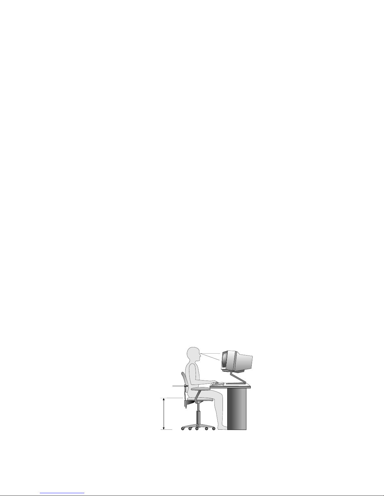
Arranging Your Workspace
Arranging Your Workspace
To get the most from your server, arrange both the equipment you
use and your work area to suit your needs and the kind of work
you do. Your comfort is of foremost importance, but light sources,
air circulation, and the location of electrical outlets also can affect
the way you arrange your workspace.
Comfort
Although no single working position is ideal for everyone, here are
a few guidelines to help you find a position that suits you best.
Sitting in the same position for a long time can cause fatigue. A
good chair can make a big difference. The backrest and seat should
adjust independently and provide good support. The seat should
have a curved front to relieve pressure on the thighs. Adjust the
seat so that your thighs are parallel to the floor and your feet are
either flat on the floor or on a footrest.
When using the keyboard, keep your forearms parallel to the floor
and your wrists in a neutral, comfortable position. Try to keep a
light touch on the keyboard and your hands and fingers relaxed.
You can change the angle of the keyboard for maximum comfort by
adjusting the position of the keyboard feet.
Viewing Distance
Lower
Back
Support
Seat
Height
Adjust the monitor so the top of the screen is at, or slightly below,
eye level. Place the monitor at a comfortable viewing distance,
70 PC Server 520 User's Handbook for PCI/EISA
Page 89

Arranging Your Workspace
usually 51 to 61 cm (20 to 24 in.), and position it so you can view it
without having to twist your body. Also position other equipment
you use regularly, such as the telephone or a mouse, within easy
reach.
Glare and Lighting
Position the monitor to minimize glare and reflections from
overhead lights, windows, and other light sources. Even reflected
light from shiny surfaces can cause annoying reflections on your
monitor screen. Place the monitor at right angles to windows and
other light sources, when possible. Reduce overhead lighting, if
necessary, by turning off lights or using lower wattage bulbs. If you
install the monitor near a window, use curtains or blinds to block
the sunlight. You might have to adjust the Brightness and Contrast
controls on the monitor as the room lighting changes throughout the
day.
Where it is impossible to avoid reflections or to adjust the lighting,
an antiglare filter placed over the screen might be helpful.
However, these filters might affect the clarity of the image on the
screen; try them only after you have exhausted other methods of
reducing glare.
Dust buildup compounds problems associated with glare.
Remember to clean your monitor screen periodically using a soft
cloth moistened with a nonabrasive liquid glass cleaner.
Air Circulation
Your server and monitor produce heat. Your server has one or
more fans that pull in fresh air and force out hot air. The monitor
lets hot air escape through vents. Blocking the air vents can cause
overheating, which might result in a malfunction or damage. Place
the server and monitor so that nothing blocks the air vents; usually,
51 mm (2 in.) of air space is sufficient. Also, make sure the vented
air is not blowing on someone else.
Chapter 2. Installing Software 71
Page 90

Installation Checklist
Electrical Outlets and Cable Lengths
The location of electrical outlets and the length of power cords and
cables that connect to the monitor, printer, and other devices might
determine the final placement of your server.
When arranging your workspace:
Avoid the use of extension cords. When possible, plug the
server power cord directly into an electrical outlet.
Keep power cords and cables neatly routed away from
walkways and other areas where they might get kicked
accidentally.
For more information about power cords, refer to the User's
Reference.
72 PC Server 520 User's Handbook for PCI/EISA
Page 91

Installation Checklist
Installation Checklist
Important
Be sure to maintain at least 51 mm (2 in.) of space at the rear of
the server to allow the server's cooling system to work properly.
Blocking the air vents can cause overheating, which might result
in a malfunction or permanent damage.
Your server hardware is set up, and you are ready to learn about
your server. The order in which you do these tasks is up to you.
Use the following checklist as a guide.
Ø Learn about your server and the system utility programs
Your server comes with utility programs to help you
configure your server and troubleshoot problems. See
Chapter 6, “Configuring Your Server” on page 273 for
information about configuring your server and using these
utility programs. See Chapter 7, “Solving Problems” on
page 299 for details about troubleshooting. If your server is a
disk-array model, read and become familiar with Chapter 3,
“Configuring the Disk Array” on page 75. Follow the
instructions to back up your disk-array configuration
information. If your server comes with a PeerMaster adapter,
read and become familiar with Chapter 4, “Configuring the
PeerMaster Adapter” on page 133.
Ø Record your identification numbers
Your server has important identification information that you
will need if you have it serviced. Appendix A, “Server
Records” on page 369 shows where to find these numbers,
and provides space to record and retain information. Be sure
to record your ServerGuide License Diskette serial number in
Appendix A.
Chapter 2. Installing Software 73
Page 92

Installation Checklist
Ø Install options
If you decided earlier to delay installing your options, you
might want to complete these installations now. See
Chapter 5, “Installing Options” on page 153 for step-by-step
installation instructions.
Ø Complete setting up your PC Server 520
If you need to set passwords or drive-startup sequences, or do
other system setup tasks, use the procedures in “Using the
Setup Program” on page 275.
Ø Install SVGA and SCSI device drivers
If you installed SVGA applications, or if you did not install
one of the operating systems from the ServerGuide CD
package, get the SVGA and SCSI device driver diskettes that
come with your server, and install these device drivers now.
If your server came with a preinstalled PeerMaster or
ServeRAID adapter, install the device drivers from the
appropriate diskette.
These diskettes contain README files to help you install
device drivers and complete your installation. Be sure to
review the README files before you install the device drivers.
Ø Install option files and monitoring programs (ServeRAID)
Some options that you install might come with a diskette that
contains device drivers, configuration files, or test programs.
To install these files (after your operating system is installed),
follow the instructions that come with the diskettes.
Ø Install application programs
To install application programs, follow the instructions
supplied with each application program.
74 PC Server 520 User's Handbook for PCI/EISA
Page 93

Ø Review your User's Reference
The User's Reference contains information about the hardware
and software features and expansion capabilities of your
server. This book also contains information about the
microprocessors, memory, data-storage devices, video
subsystems, input and output (I/O) ports, SCSI subsystem,
and security. For your convenience, the User's Reference also
includes a glossary and product warranty information.
Chapter 2. Installing Software 75
Page 94

Device Drivers
76 PC Server 520 User's Handbook for PCI/EISA
Page 95

Chapter 3. Configuring the Disk Array
The information in this chapter applies only to models that have an
IBM PC ServeRAID Adapter installed. This chapter provides
step-by-step procedures to perform the tasks necessary to configure,
add, change, or delete one or more disk arrays. In addition, this
chapter outlines procedures for some of the more common
disk-array configuration and maintenance tasks.
After you complete the instructions in this chapter, you must install
an operating system. Review the software and operating
system-considerations in Chapter 2, “Installing Software” on
page 21; then, follow the instructions in your operating
system-documentation.
This chapter contains:
Before You Begin
............................ 79
Device Drivers . . . . . . . . . . . . . . . . . . . . . . . . . . . . . . 79
Administration and Monitoring Utilities .............. 80
Monitoring the Adapter Status in a Local System ....... 81
Monitoring Adapter Status from a Remote System ...... 81
RAID Technology . . . . . . . . . . . . . . . . . . . . . . . . . . . . 82
Hard Disk Drive Capacities .................... 82
Additional Storage Capacity .................... 83
The ServeRAID Configuration Program Screens ........ 83
Starting the ServeRAID Configuration Program .......... 86
The ServeRAID Adapter Main Menu ............... 87
Viewing the ServeRAID Configuration ............... 90
Performing Common Tasks ...................... 91
Creating a Disk Array ........................ 91
Defining Logical Drives ....................... 93
Defining a Hot-Spare Drive .................... 98
Deleting a Disk Array ........................ 99
Deleting a Logical Drive ..................... 101
Redefining Space in an Array .................. 102
Drive Maintenance . . . . . . . . . . . . . . . . . . . . . . . . . . 104
Obtaining Drive Status ...................... 104
Defining the State of a Drive ................... 108
Results of a Hard Disk Drive Failure .............. 110
Logical and Hard Disk Drive Status Indications ....... 111
Replacing a Faulty Drive ..................... 112
Rebuilding a Logical Drive .................... 115
Copyright IBM Corp. 1995, 1996 77
Page 96

Resetting the Adapter Configuration ................ 117
Viewing Configuration Changes ................. 119
Synchronizing the Adapter Configuration ........... 120
Running RAID Subsystem Diagnostic Tests ........... 121
Additional Disk-Array Tasks .................... 122
Backing Up Your Disk-Array Configuration .......... 122
Restoring the Disk-Array Configuration ............ 123
Changing the Write Policy .................... 123
Formatting Drives . . . . . . . . . . . . . . . . . . . . . . . . . 126
Changing the RAID Parameters ................. 127
Changing the ServeRAID Adapter Parameters ........ 130
Using the Mini-Configuration Program .............. 133
Viewing the Adapter Status ................... 134
Viewing Configuration Information ............... 135
Using Advanced Configuration Functions ........... 135
78 PC Server 520 User's Handbook for PCI/EISA
Page 97

Device Drivers
Before You Begin
Familiarize yourself with the information contained in this
chapter and the RAID (redundant array of independent disks)
information in the User's Reference.
Verify the disk-array configuration. The hard disk drives in
your disk-array model come configured as one logical drive.
– To view the disk-array configuration, go to “Viewing the
ServeRAID Configuration” on page 90.
– To create a disk array, go to “Creating a Disk Array” on
page 91.
Backup the disk-array configuration. See “Backing Up Your
Disk-Array Configuration” on page 122.
After you configure the disk array, you can complete setup by
installing your operating system (from the ServerGuide compact
disc that comes with your server or from the diskettes that come
with your operating system). Before you install an operating
system, review the README file in Start Here on the ServerGuide
Main CD. To install your operating system from the ServerGuide
CD, see “About ServerGuide” on page 27 for instructions.
Device Drivers
The ServeRAID adapter requires the installation of device drivers.
See the README file on the Device Driver/Administration and
Monitoring diskette for detailed instructions.
If you install an operating system from the ServerGuide CD, the
device drivers will be installed automatically. However, if you
install your operating system from diskettes, you will need to install
the device drivers. See the README file on the Device
Driver/Administration and Monitoring diskette for installation
instructions.
Chapter 3. Configuring the Disk Array 79
Page 98
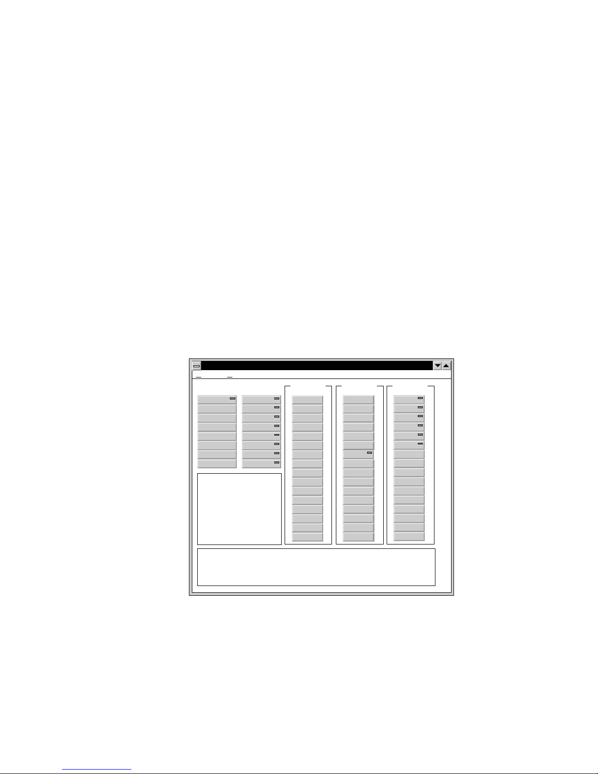
Administration and Monitoring Utilities
Administration and Monitoring Utilities
The Administration and Monitoring program contains RAID
monitoring utility programs for several operating systems that your
ServeRAID adapter supports. You can monitor your ServeRAID
configuration program in the local and remote systems by using
these programs.
The following is an example of an Administration and Monitoring
program screen. Your screen might look different.
CHANNEL3
ONL
A
ONL
A
ONL
B
ONL
B
HSP
ONL
SBY
Adapter1 LogDrv0
LogDrv1
LogDrv2
LogDrv3
LogDrv4
LogDrv5
LogDrv6
LogDrv7
Adapter2
Adapter3
Adapter4
Adapter5
Adapter6
Adapter7
Adapter8
B
CHANNEL2CHANNEL1
OptionsHelp
IBMPCServerRaidAdministratorandMonitor
Initiator
Initiator
Initiator
TueFeb2715:49:471996
Adapter1:rebuildcompleted
TueFeb2715:46:111996
Adapter1:rebuildstarted
TueFeb2715:45:081996
Adapter1:deaddrivedetected
Channel=3,Bay=6
Thisisthehelpwindowforthisapplication.Helpisgivenhereasthemousepointerpassesover
objectsinthisapplication.
80 PC Server 520 User's Handbook for PCI/EISA
Page 99

Administration and Monitoring Utilities
Monitoring the Adapter Status in a Local System
The Device Driver/Administration Monitoring Program diskette
provides monitoring programs that you can use to perform
disk-array maintenance tasks. Because the monitoring programs
reside on top of your operating system, you do not need to restart
the server. Instead, you can perform tasks such as the following
from your active operating system desktop:
Select the adapter that you want to monitor.
View information about drives connected to the adapter, and
change the drive state.
Reassign a drive to replace a defunct drive.
Some operating systems provide additional features, such as adding
and deleting a logical drive. Refer to the README file on the
Device Driver/Administration and Monitoring diskette for specific
information and installation instructions.
Monitoring Adapter Status from a Remote System
The ServeRAID Administration and Monitoring programs support
the Client/Server environment using TCP/IP on a variety of
platforms. The server programs run on the system containing a
ServeRAID adapter and is supported on a number of operating
systems. See the README file on the Device
Driver/Administration and Monitoring diskette for more
information. The Client program runs in various Windows
environments:
Windows NT Server Version 3.51
Windows NT Workstation Version 3.51
Windows 95
The Client program includes many of the functions contained in the
ServeRAID configuration program. Because it resides on top of
your operating system, you do not need to restart the server to add
and remove capacity dynamically when creating or deleting an
array. You can start the Administration and Monitoring program
from your active operating system desktop.
Chapter 3. Configuring the Disk Array 81
Page 100

RAID Technology
This monitoring program allows you to view the ServeRAID
configuration and associated devices, reassign a drive to replace a
defunct drive, create a logical drive, create an array, and delete an
array.
In addition, in an array that contains only one logical drive, and the
total number of logical drives in all arrays is less than 7, you can
change the logical drive RAID level from level 0 to level 5 (or level
5 to level 0).
See the README file on the Device Driver/Administration and
Monitoring diskette for instructions on installing and using this
monitoring utility.
RAID Technology
RAID is the technology of grouping several hard disk drives in a
server into an array that can be defined as a single logical drive.
This logical drive then appears to the operating system as a single
physical drive. This grouping technique greatly enhances
logical-drive capacity and performance. In addition, if one of the
hard-disk drives fails (becomes defunct) the system continues to
run, with no operator intervention required, at reduced
performance. You can replace the defunct drive without turning off
the server (hot-swap). For more information about hot-swappable
hard disk drives, see “Installing Internal Drives” on page 197.
Hard Disk Drive Capacities
With a server, it is important to understand the implications of hard
disk drive capacities and how they influence the way you create
disk arrays.
82 PC Server 520 User's Handbook for PCI/EISA
 Loading...