

Page 1

ERserver
iSeries
Setting Up Your
0578, 5074, 5078 or 5079
Expansion Unit
Version 5
SA41-5149-02
Page 2

Page 3

ER s e r v e r
iSeries
Setting Up Your
0578, 5074, 5078 or 5079
Expansion Unit
Version 5
SA41-5149-02
Page 4

Note
Before using this information and the product it supports, be sure to read the information in
“Safety and Environmental Notices” on page v and “Notices” on page 51.
Third Edition (August 2002)
This edition applies only to reduced instruction set computer (RISC)) systems.
© Copyright International Business Machines Corporation 2000, 2002. All rights reserved.
US Government Users Restricted Rights – Use, duplication or disclosure restricted by GSA ADP Schedule Contract
with IBM Corp.
Page 5

Contents
Safety and Environmental Notices . . . v
Danger Notices .............v
Caution Notices .............v
Laser Safety Information .........vi
Product Recycling and Disposal.......vi
Battery Return Program .........vi
Environmental Design ..........vi
About Setting up your 0578, 5074, 5078
or 5079 Expansion Unit (SA41–5149) . . vii
Who should read this book .........vii
Prerequisite and related information ......vii
iSeries Navigator ............vii
How to send your comments ........viii
Chapter 1. Preparing to set up your 5074
or 5079 Expansion Unit ........1
Hardwarerequirements...........1
Site planning considerations for the 5079 .....1
Identifying HSL and SPCN Cables ......2
Planning your cable layout ........2
Configurationrules...........5
Powering down your iSeries system unit .....6
Chapter 2. Setting up your 5074
expansion unit ............9
Connecting your 5074 directly to your system unit . 9
Connecting your 5074 to another expansion unit . . 10
Connecting your 5074 at the beginning of a loop 11
Connecting your 5074 to the middle of a loop . . 13
Connecting your 5074 to the end of a loop . . . 14
Connecting your 5079 at the beginning of a loop 22
Connecting your 5079 in the middle of a loop . . 24
Connecting your 5079 to the end of a loop . . . 25
Chapter 5. Completing your installation 27
Chapter 6. Verifying Your New
Configuration ............29
Appendix A. Removing the back covers 31
5075 and 820 back cover ..........31
5074, 830 and 890 back cover ........31
5079 and 840 back cover ..........32
Accessing units in a rack ..........34
Appendix B. Connector Locations . . . 35
820 HSL connector locations .........35
830 HSL connector locations .........36
840 HSL connector locations .........37
890 HSL connector locations .........38
5079 connector locations ..........39
5074 connector locations ..........40
5075 connector locations ..........41
5078 connector locations ..........41
Appendix C. System unit control panel 43
Appendix D. Cabling rules for systems
with a migration unit or the 9079 and
9094 expansion unit .........45
Chapter 3. Setting up your 0578
expansion unit ...........15
Connecting your 0578 directly to your system unit 15
Chapter 4. Setting up your 5079
Expansion Unit ...........19
Connecting your 5079 directly to your system unit 19
Connecting your 5079 to another expansion unit . . 22
© Copyright IBM Corp. 2000, 2002 iii
Notices ..............51
Trademarks..............52
Electronic Emission Notices .........53
Federal Communications Commission (FCC)
Statement..............53
Electronic Emission Notices .........54
Federal Communications Commission (FCC)
Statement..............54
Page 6

iv Setting up your 0578, 5074, 5078 or 5079 Expansion Unit V5R2
Page 7

Safety and Environmental Notices
Danger Notices
A danger notice calls attention to a situation that is potentially lethal or extremely
hazardous to people.
DANGER
An electrical outlet that is not correctly wired could place hazardous voltage
on metal parts of the system or the products that attach to the system. It is the
customer’s responsibility to ensure that the outlet is correctly wired and
grounded to prevent an electrical shock. (RSFTD201)
DANGER
To prevent a possible electrical shock when installing the system, ensure that
the power cords for all devices are unplugged before installing signal cables.
(RSFTD202)
DANGER
To prevent a possible electrical shock when adding or removing any devices
to or from the system, ensure that the power cords for those devices are
unplugged before the signal cables are connected or disconnected. If possible,
disconnect all power cords from the existing system before you add or
remove a device. (RSFTD203)
Caution Notices
DANGER
To prevent a possible electrical shock during an electrical storm, do not
connect or disconnect cables or station protectors for communications lines,
display stations, printers, or telephones. (RSFTD003)
DANGER
To prevent a possible electrical shock from touching two surfaces with
different electrical grounds, use one hand, when possible, to connect or
disconnect signal cables. (RSFTD004)
A caution notice calls attention to a situation that is potentially hazardous to
people because of some existing condition.
CAUTION:
Telecommunications Statement: This unit contains over-voltage circuits between
the ac power outlet and the unit. These circuits meet the standard limits
described in International Electrical Commission (IEC) 664, installation category
II. It is the customer’s responsibility to ensure that the power outlet meets the
standards of IEC 664, installation category II. (RSFTC214)
© Copyright IBM Corp. 2000, 2002 v
Page 8

Laser Compliance
All Lasers are certified in the U.S. to conform to the requirements of DHHS 21 CFR
Subchapter J for class 1 laser products. Outside the U.S., they are certified to be in
compliance with the IEC 825 (first edition 1984) and as a class 1 laser product.
Consult the label on each part for laser certification numbers and approval
information.
Laser Safety Information
CAUTION:
This product may contain a CD-ROM which is a class 1 laser product.
(RSFTC240)
CAUTION:
All IBM laser modules are designed so that there is never any human access to
laser radiation above a class 1 level during normal operation, user maintenance,
or prescribed service conditions. Data processing environments can contain
equipment transmitting on system links with laser modules that operate at
greater than class 1 power levels. For this reason, never look into the end of an
optical fiber cable or open receptacle. Only trained service personnel should
perform the inspection or repair of optical fiber cable assemblies and
receptacles. (RSFTC243)
Product Recycling and Disposal
Components of the system, such as structural parts and circuit cards, can be
recycled where recycling facilities exist. IBM does not currently collect and recycle
used IBM products from customers in the United States other than those products
that are involved in trade-in programs. Companies are available to disassemble,
reutilize, recycle, or dispose of electronic products. Contact an IBM account
representative for more information.
The system unit contains batteries and circuit boards with lead solder. Before you
dispose of this unit, these batteries and circuit boards must be removed and
discarded according to local regulations or recycled where facilities exist. This book
contains specific information on each battery type where applicable.
Battery Return Program
In the United States, IBM has established a collection process for reuse, recycling,
or proper disposal of used IBM batteries and battery packs. For information on
proper disposal of the batteries in this unit, please contact IBM at 1-800-426-4333.
Please have the IBM part number that is listed on the battery available when you
make your call. For information on battery disposal outside the United States,
contact your local waste disposal facility.
Environmental Design
The environmental efforts that have gone into the design of the system signify
IBM’s commitment to improve the quality of its products and processes. Some of
these accomplishments include the elimination of the use of Class I
ozone-depleting chemicals in the manufacturing process, reductions in
manufacturing wastes, and increased product energy efficiency. For more
information, contact an IBM account representative.
vi Setting up your 0578, 5074, 5078 or 5079 Expansion Unit V5R2
Page 9

About Setting up your 0578, 5074, 5078 or 5079 Expansion Unit (SA41–5149)
This book contains installation about setting up your expansion unit. You may elect
to set up your new expansion unit yourself. It will take approximately one to three
hours to install the hardware
You also may elect not to install the expansion unit yourself. You may contact IBM
or an authorized dealer to make arrangements for them to install it for a fee.
Who should read this book
You should be familiar with the iSeries system, display, and keyboards. You should
also know how to power down the system and perform a system initial program
load. You should also know how to power down system peripherals such as
printers, monitors, and PCs.
Prerequisite and related information
Use the iSeries Information Center as your starting point for looking up iSeries
technical information.
You can access the Information Center two ways:
v From the following Web site:
http://www.ibm.com/eserver/iseries/infocenter
v From CD-ROMs that ship with your Operating System/400 order:
iSeries Information Center, SK3T-4091-02. This package also includes the PDF
versions of iSeries manuals, iSeries Information Center: Supplemental Manuals,
SK3T-4092-01, which replaces the Softcopy Library CD-ROM.
The iSeries Information Center contains advisors and important topics such as
Java, TCP/IP, Web serving, secured networks, logical partitions, clustering, CL
commands, and system application programming interfaces (APIs). It also includes
links to related IBM Redbooks and Internet links to other IBM Web sites such as
the Technical Studio and the IBM home page.
With every new hardware order, you receive the iSeries Setup and Operations
CD-ROM, SK3T-4098-01. This CD-ROM contains IBM Eserver iSeries Access for
Windows and the EZ-Setup wizard. iSeries Access offers a powerful set of client
and server capabilities for connecting PCs to iSeries servers. The EZ-Setup wizard
automates many of the iSeries setup tasks.
iSeries Navigator
IBM iSeries Navigator is a powerful graphical interface for managing your iSeries
servers. iSeries Navigator functionality includes system navigation, configuration,
planning capabilities, and online help to guide you through your tasks. iSeries
Navigator makes operation and administration of the server easier and more
productive and is the only user interface to the new, advanced features of the
OS/400 operating system. It also includes Management Central for managing
multiple servers from a central system.
© Copyright IBM Corp. 2000, 2002 vii
Page 10

You can find more information on iSeries Navigator in the iSeries Information
Center and at the following Web site:
http://www.ibm.com/eserver/iseries/navigator/
How to send your comments
Your feedback is important in helping to provide the most accurate and
high-quality information. If you have any comments about this book or any other
iSeries documentation, fill out the readers’ comment form at the back of this book.
v If you prefer to send comments by mail, use the readers’ comment form with the
address that is printed on the back. If you are mailing a readers’ comment form
from a country other than the United States, you can give the form to the local
IBM branch office or IBM representative for postage-paid mailing.
v If you prefer to send comments by FAX, use either of the following numbers:
– United States, Canada, and Puerto Rico: 1-800-937-3430
– Other countries: 1-507-253-5192
v If you prefer to send comments electronically, use one of these e-mail addresses:
– Comments on books:
RCHCLERK@us.ibm.com
– Comments on the iSeries Information Center:
RCHINFOC@us.ibm.com
Be sure to include the following:
v The name of the book or iSeries Information Center topic.
v The publication number of the book.
v The page number or topic of a book to which your comment applies.
viii Setting up your 0578, 5074, 5078 or 5079 Expansion Unit V5R2
Page 11

Chapter 1. Preparing to set up your 5074 or 5079 Expansion Unit
This chapter explains what you need to do before you set up your 5074 or 5079
Expansion Unit. This includes the following tasks:
1. Unpack your expansion unit (refer to the instructions for unpacking that came
with your expansion unit).
2. Plan layouts for your cables.
3. Power down your system unit.
Before you begin the installation process, carefully plan where you will install your
new expansion unit. You should consider several factors that include size, security,
and environmental factors. Before you set up your new expansion unit, refer to the
iSeries Information Center Web site
http://www.ibm.com/eserver/iseries/infocenter
and select Plan for hardware and software
Hardware requirements
If you are installing your new expansion unit directly to your system unit, you
should remember these rules:
v You need to have an available or unused high speed link (HSL) connector.
v You need to have an unused or available system power control network (SPCN)
connector.
Site planning considerations for the 5079
Weight and Size of the 5079
Table 1 shows the weight and dimensions of the 5079 Expansion Unit.
Table 1. 5079 Weight and Size descriptions
Weight (fully configured) 1600 lb (725 kg)
Width 25.5 in (650 mm)
Depth 40 in (1020 mm)
Height 71 in (1800 mm)
The 5079 has a floor loading of 86 lb/ft2(420 kg/m2). Because of the size and
weight of the 5079, you should do the following:
CAUTION:
Overlapping the clearance defined below with adjacent equipment results in a
significant increase in the amount of floor loading.
v Contact your facility or structural engineer to determine a safe site for your
5079.
v Leave 30 in. (762 mm) of clearance to the front and back of the 5079.
v Leave 5 in. (127 mm) of clearance to the left and right of the 5079.
© Copyright IBM Corp. 2000, 2002 1
Page 12

Identifying HSL and SPCN Cables
Use the following tables to identify your High Speed link (HSL) and System Power
Control Network cables. Your system uses HSL cables to communicate with your
expansion unit. Your system uses SPCN cables to control power to your expansion
unit.
Depending on your requirements, you might not have every HSL or SPCN cable
listed below.
Table 2. HSL Cables
Feature Number CCIN Number Length Part Number
1460 (copper) 0343 3 Meters 44L0005
1461 (copper) 0361 6 Meters 97H7490
1462 (copper) 0368 15 Meters 97H7491
1470 (optical) 1470 6 Meters 21P5014
1471 (optical) 1471 30 Meters 21P5015
1472 (optical) 1472 100 Meters 21P5016
1473 (optical) 1473 250 Meters 21P6326
1474 (copper) 1474 6 Meters 21P5477
1475 (copper) 1475 15 Meters 21P5458
1481 (copper) 1481 1 Meter 21P5454
1482 (copper) 1482 3.5 Meters 53P2676
1483 (copper) 1483 10 Meters 21P5456
1485 (copper) 1485 15 Meters 21P5457
Table 3. SPCN Cables
Feature Number CCIN number Length Part Number
1463 9206 2 Meters 87G6235
1464 9219 6 Meters 21F9469
1465 9213 15 Meters 21F9358
1466 9214 30 Meters 21F9359
0369 (optical) 0369 100 Meters 21F9415
1468 (optical) 1468 250 Meters 21P6325
Planning your cable layout
When you decide where to place your cables, follow your site plan and keep the
following things in mind:
v Refer to
http://www.ibm.com/eserver/iseries/infocenter
and select Plan for hardware and software—Cabling instructions
v Avoid creating a safety hazard.
v Avoid damaging the cables.
v Avoid placing cables parallel to high-voltage lines.
2 Setting up your 0578, 5074, 5078 or 5079 Expansion Unit V5R2
Page 13
Placing power cords for the 5079
You need to provide the appropriate receptacles for the power cords shipped with
your 5079. The usable length of the upper unit power cord is 4 ft. (1.2 m) shorter
than the length of the lower unit power cord.
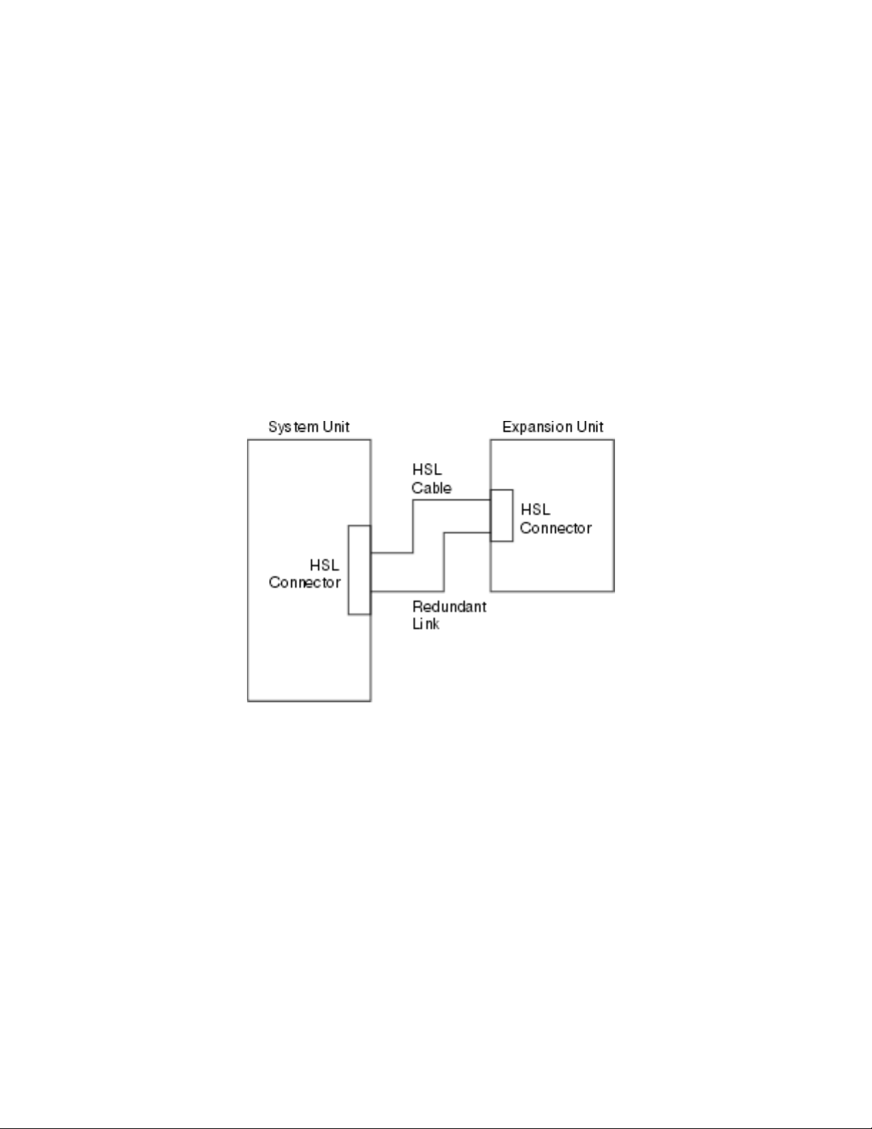
Redundant links
A redundant link is a secondary HSL connection that your system can use if the
primary link experiences a failure. You can create a redundant link configuration
by connecting an extra HSL cable link between the expansion units and the system
unit.
Your new expansion unit has disk units. To ensure continued access to your disk
units in the event of a link failure, use a redundant link configuration when you
plan your cable layout.
Refer to Figure 1 to see how to plan your cables with a redundant link
configuration with one expansion unit. If you are linking two, expansion units
refer to Figure 2 on page 4. If you are setting up a 5079, refer to Figure 3 on page 4.
Figure 1. Planning for redundant link one expansion unit
Chapter 1. Preparing to set up your 5074 or 5079 Expansion Unit 3
Page 14
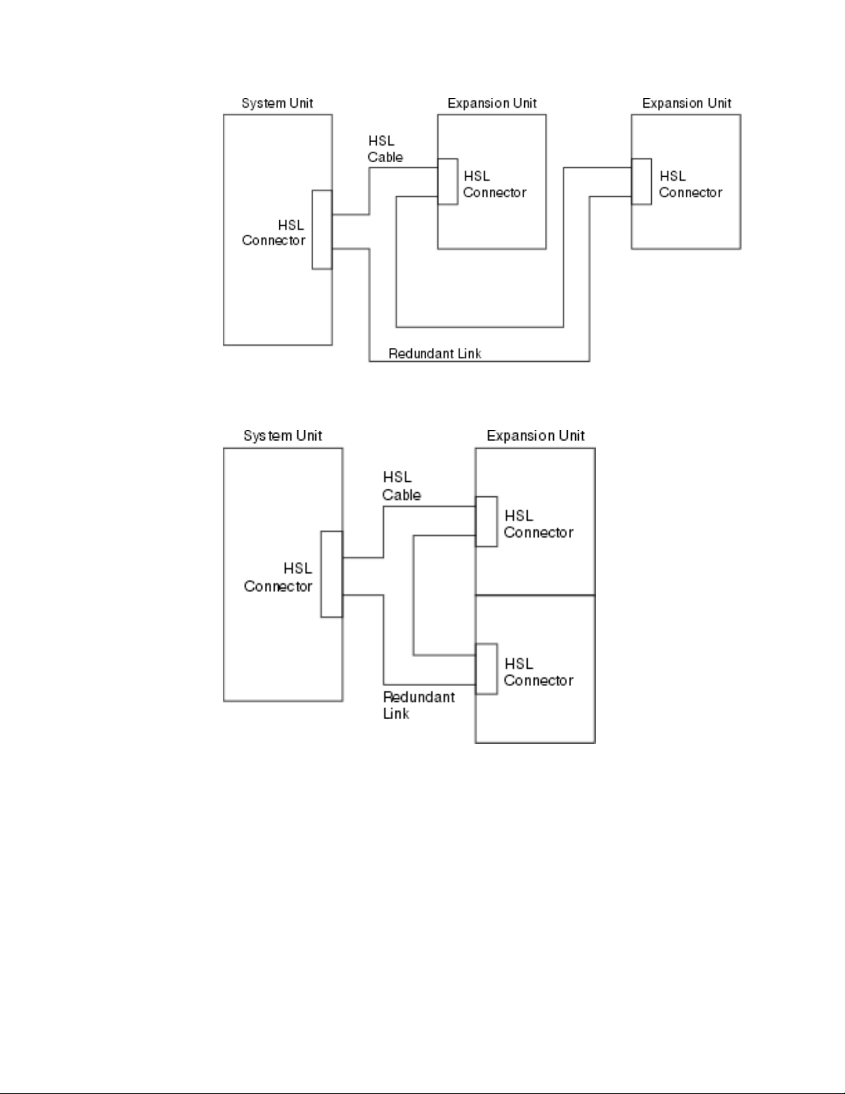
Figure 2. Planning for redundant link with two expansion units
Figure 3. Planning for redundant link with stacked expansion units (5079)
4 Setting up your 0578, 5074, 5078 or 5079 Expansion Unit V5R2
Page 15
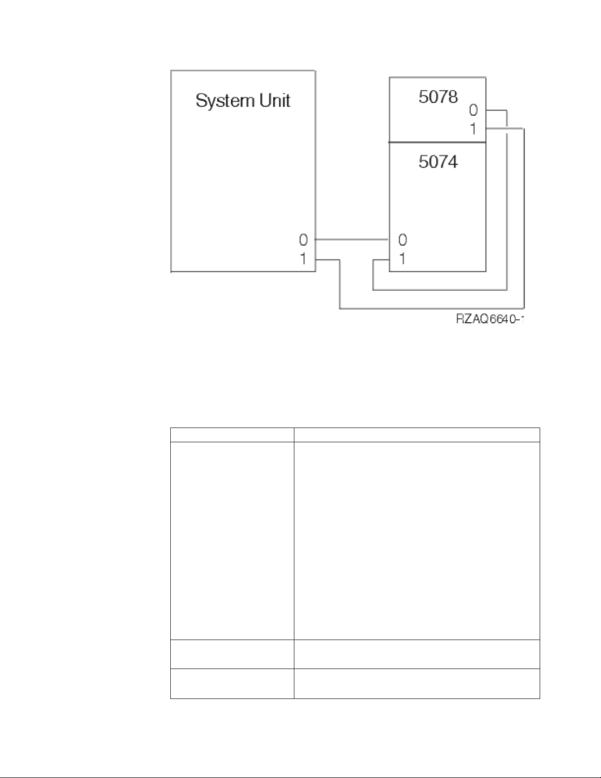
Figure 4. Planning for redundant link with a expansion unit and 5078
Configuration rules
When you set up your expansion unit, observe the rules in Table 4.
Table 4. Configuration rules
System or expansion unit Configuration rules
General
5079 expansion unit
iSeries 820
v When connecting HSL cables from the system unit to an
expansion unit:
– Connect the first HSL cable between connector A0 on
the system unit (or the first available set of connectors)
and connector 0 on your expansion unit.
– Connect the last HSL cable between connector A1 on
the system unit (or the first available set of connectors)
and connector 1 on your expansion unit.
v When connecting HSL cables between expansion units:
– Connect the HSL cable to connector 1 on the first
expansion unit and to connector 0 on the next
expansion unit.
v Connect an SPCN cable from J15 on the system unit to
J15 on the expansion unit.
v Connect an SPCN cable from J16 on the expansion unit to
J15 on the next expansion unit.
v The 5079 expansion unit counts as two 5074 expansion
units.
v The 820 can have up to five expansion units in one HSL
loop.
Chapter 1. Preparing to set up your 5074 or 5079 Expansion Unit 5
Page 16

Table 4. Configuration rules (continued)
System or expansion unit Configuration rules
iSeries 830
iSeries 840
iSeries 890
v The 830 can have a maximum of 13 expansion units on
four HSL loops.
v Connect HSL loops to the 830 in this order (see
Appendix B, “Connector Locations” on page 35):
1. B0 and B1
2. C0 and C1
3. D0 and D1
4. A0 and A1
v Connectors A0 and A1, can have one 5074.
v Connectors B0 and B1; C0 and C1; D0 and D1, can have
up to four expansion units.
v These rules apply for all expansion units except
migration units which always go on A0 and A1.
v The 840 can have a maximum of 23 expansion units.
v The 840 can have a maximum of eight HSL loops.
v Each HSL loop can have a maximum of four expansion
units.
v The 890 can have a maximum of 47 expansion units.
v The 890 can have a maximum of 32 external xSeries
servers.
v The 890 can have a maximum of 12 HSL loops on a
24–way and 14 HSL loops on a 32–way.
v The 890 can have a maximum of five external xSeries
servers per loop.
Powering down your iSeries system unit
You need to power down your system unit before you can connect your new
expansion unit to it. Follow the steps below to power down your system unit.
__ 1. Ensure that you have a current backup of your operating system and
licensed programs. If you have backed up the operating system and licensed
programs since the last time you applied program temporary fixes (PTFs),
that backup is acceptable.
__ 2. If you have installed logical partitions on your system unit, refer to Logical
partitions in the iSeries Information Center.IntheiSeries Information Center you
can find instructions on powering down a system with logical partitions.
__ 3. Ensure that all jobs are complete.
__ 4. When all jobs are complete, type pwrdwnsys *immed on an command line and
press the Enter key.
Note: If you encounter difficulties during the installation, contact your authorized
dealer or service provider.
__ 5. After your system unit has completely powered down, power off all PCs
and devices, such as printers and display stations, that are connected to the
system unit.
__ 6. Unplug any power cords, such as for printers, expansion units, and display
stations, that are connected to the system unit.
__ 7. Unplug the power cord for the system unit from the electrical outlet.
6 Setting up your 0578, 5074, 5078 or 5079 Expansion Unit V5R2
Page 17

If you are setting up a 5074 Expansion Unit, go to Chapter 2, “Setting up your 5074
expansion unit” on page 9.
If you are setting up a 5079 Expansion Unit, go to Chapter 4, “Setting up your 5079
Expansion Unit” on page 19.
Chapter 1. Preparing to set up your 5074 or 5079 Expansion Unit 7
Page 18

8 Setting up your 0578, 5074, 5078 or 5079 Expansion Unit V5R2
Page 19

Chapter 2. Setting up your 5074 expansion unit
This chapter describes how to set up your 5074 Expansion Unit. If you are setting
up a 5079 Expansion Unit, go to Chapter 4, “Setting up your 5079 Expansion Unit”
on page 19.
If you have not powered down your system unit, go to “Powering down your
iSeries system unit” on page 6. Once you have powered down your system unit,
return here.
Removing the covers
See Appendix A, “Removing the back covers” on page 31 if you need help
removing the covers on your expansion units or system unit.
Connector locations
See Appendix B, “Connector Locations” on page 35 if you need help finding the
connectors on your expansion units or system unit.
Systems with a migration unit or 9079 Expansion Unit
If your system unit has a migration unit or 9079 Expansion Unit, read Appendix D,
“Cabling rules for systems with a migration unit or the 9079 and 9094 expansion
unit” on page 45 before you proceed.
Connecting your 5074 directly to your system unit
This section describes how to connect your 5074 directly to your iSeries system
unit. If you are connecting a 5074 to a loop with other expansion units, skip this
chapter and go to “Connecting your 5074 to another expansion unit” on page 10.
Note: This note only applies if your system unit is an iSeries server 830. Connect
HSL loops to the 830 in this order:
1. B0 and B1
2. C0 and C1
3. D0 and D1
4. A0 and A1
Connect HSL loops A0 and A1 only after the other three sets of HSL
connectors are used.
If you encounter difficulties during the procedure, contact your authorized dealer
or service provider.
__ 1. Locate available HSL connectors on your system unit.
__ a. Remove or open the back cover for your system unit. See
Appendix A, “Removing the back covers” on page 31 if you need
instructions.
__ b. Find the first set of unused HSL connectors on the back of your
system unit (Appendix B, “Connector Locations” on page 35).
© Copyright IBM Corp. 2000, 2002 9
Page 20

If you have just one set of HSL connectors on your system unit, they
are labeled A0 and A1.
If you have more than one set of HSL connectors on your system
unit, the first set is labeled A0 and A1. The remaining HSL connectors
are labeled alphabetically. For example, if you have an 830, there are
four sets of HSL connectors on your system. They are labeled A0 and
A1; B0 and B1; C0 and C1; D0 and D1.
Unused HSL connectors are covered with metal clips. Remove the
clips before you install the HSL cables.
__ c. Write down which set of HSL connectors are available here: _____ ,
_____.
__ 2. Connect the cables to your 5074.
__ a. Find the HSL cables, SPCN cable, and power cable that is shipped
with your expansion unit.
__ b. Attach a label to each end of the HSL cables.
__ c. Label one HSL cable 0 at both ends.
__ d. Label the other HSL cable 1 at both ends.
__ e. Remove the back cover for your expansion unit. See Appendix A,
“Removing the back covers” on page 31 if you need information
about removing the cover.
__ f. Connect the HSL cable that is labeled 0 to the HSL connector that is
labeled 0 on your 5074.
__ g. Connect the HSL cable that is labeled 1 to the HSL connector that is
labeled 1 on your 5074.
__ h. Connect the SPCN cable to connector J15 on your 5074.
__ i. Connect the power cable. Do not plug into the wall outlet.
__ j. Close or replace the back cover to your 5074.
__ 3. Connect the cables from your 5074 to your system unit.
__ a. Connect the HSL cable that is labeled 0 to the corresponding HSL
connector that you found in step 1c.
__ b. Connect the HSL cable that you labeled 1 to the corresponding HSL
connector that you found in step 1c.
__ c. Connect the SPCN cable that comes from your expansion unit to the
connector that is labeled J15.
__ 4. If you are installing a new iSeries server with this expansion unit, return to
the Cabling instructions.
__ 5. Go to Chapter 5, “Completing your installation” on page 27.
Connecting your 5074 to another expansion unit
This section contains instructions for connecting your 5074 expansion unit to a loop
with other expansion units. You can only connect your 5074 with other expansion
units that have HSL hardware.
This section contains three separate procedures. Follow the procedure that best
matches your system’s configuration:
v “Connecting your 5074 at the beginning of a loop” on page 11.
v “Connecting your 5074 to the middle of a loop” on page 13.
v “Connecting your 5074 to the end of a loop” on page 14.
10 Setting up your 0578, 5074, 5078 or 5079 Expansion Unit V5R2
Page 21
Notes:
1. The graphics that follow designate the HSL connectors for the system unit as 0
and 1. These designations represent which set of connectors on your system
unit the HSL loop is connected to (for example B0 and B1).
2. These procedures are intended as a guide. Some steps in the following
procedures may vary depending on the number of HSL connectors you
received in your order. Make sure that you follow the configurations rules in
Table 4 on page 5.
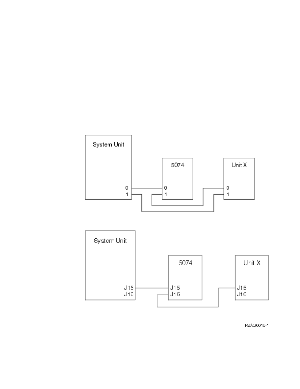
Connecting your 5074 at the beginning of a loop
Use this procedure to connect your 5074 in the first position in a loop of expansion
units. In this procedure you will connect your 5074 between your system unit and
the expansion unit which is currently in the first position. These instructions refer
to the expansion unit which is currently in the first position as unit X as is shown
in Figure 5 and Figure 6.
Figure 5. HSL connections
Figure 6. SPCN connections
Chapter 2. Setting up your 5074 expansion unit 11
Page 22

Figure 7. 5078 connections
__ 1. Remove or open the back cover from your 5074. See Appendix A,
“Removing the back covers” on page 31 if you need instructions.
__ 2. Connect the cables to the 5074. See Appendix B, “Connector Locations” on
page 35 if you need information about finding connectors.
__ a. Connect a new HSL cable to HSL connector 1.
__ b. Connect a new SPCN cable to connector J16.
__ c. Connect the power cable. Do not plug into the wall outlet.
__ 3. Remove the back cover from your system unit.
__ 4. Remove the back cover from unit X.
__ 5. At unit X, remove the HSL cable from HSL connector 0. This cable is the
HSL cable that runs between unit X and your system unit.
__ 6. At unit X, remove the SPCN cable from connector J15. This cable is the
SPCN cable that runs between unit X and your system unit.
__ 7. Connect the HSL cable from your system unit to the HSL connector 0 on
your 5074. This cable should now run between your system unit and your
5074.
__ 8. Connect the SPCN cable from your system unit to the SPCN connector J15
on your 5074. This cable should now run between your system unit and
your 5074.
__ 9. Connect the HSL cable from your 5074 HSL connector 1 to HSL connector 0
on unit X. This cable should now run between your 5074 and Unit X.
__ 10. Connect the SPCN cable from your 5074 connector J16 to connector J15 on
unit X. This cable should now run between your 5074 and Unit X.
__ 11. Install or close the covers on unit X, your 5074, and your system unit.
__ 12. Go to Chapter 5, “Completing your installation” on page 27.
12 Setting up your 0578, 5074, 5078 or 5079 Expansion Unit V5R2
Page 23

Connecting your 5074 to the middle of a loop
Use this procedure if you are connecting your 5074 to the middle of a loop. In
other words, you are connecting your 5074 between two other expansion units.
Refer to these expansion units as unit X and unit Y as is shown in Figure 8 and
Figure 9.
Figure 8. HSL connections
Figure 9. SPCN connections
__ 1. Remove the back cover from unit X, unit Y, and your 5074. See
Appendix A, “Removing the back covers” on page 31 if you need
instructions.
__ 2. At unit Y remove the SPCN cable from connector J15.
__ 3. At unit Y remove the HSL cable from connector 0.
__ 4. Connect the cables to your 5074. See Appendix B, “Connector Locations” on
page 35 if you need information about finding connectors.
__ a. Connect a new HSL cable to HSL connector 1.
__ b. Connect a new SPCN cable to connector J16.
__ c. Connect the power cable. Do not plug into the wall outlet.
__ 5. Connect the HSL cable from unit X to the HSL connector 0 on your 5074.
This cable now runs between unit X and your 5074.
__ 6. Connect the SPCN cable from unit X to the SPCN connector J15 on your
5074. This cable now runs between unit X and your 5074.
__ 7. Connect the HSL cable that you installed to connector 1 on your 5074 from
your 5074 to connector 0 on unit Y.
__ 8. Connect SPCN cable that you installed to connector J16 on your 5074 to
connector J15 on your unit Y.
__ 9. Install or close the back cover of your 5074, unit X, and unit Y.
__ 10. Go to Chapter 5, “Completing your installation” on page 27.
Chapter 2. Setting up your 5074 expansion unit 13
Page 24

Connecting your 5074 to the end of a loop
Use this procedure to connect your 5074 in the last position in a loop of expansion
units. In this procedure you will connect your 5074 between your system unit and
the expansion unit which is currently in the last position. Refer the expansion unit
which is currently in the last position as unit Y as is shown in Figure 10 and
Figure 11.
Figure 10. HSL Connections
Figure 11. SPCN Connections
__ 1. Remove or open the back cover from your 5074. See Appendix A,
“Removing the back covers” on page 31 if you need directions.
__ 2. Connect the cables to the 5074. See Appendix B, “Connector Locations” on
page 35 if you need information about finding connectors.
__ a. Connect a new HSL cable to the HSL connector 0.
__ b. Connect a new SPCN cable to connector J15.
__ c. Connect the power cable. Do not plug into the wall outlet.
__ 3. Remove the back cover from your system unit.
__ 4. Remove the back cover from unit Y.
__ 5. At unit Y, remove the HSL cable at connector 1. This cable currently runs
between unit Y and your system unit.
__ 6. Connect the HSL cable from your system unit to the HSL connector 1 on
your 5074.
__ 7. Connect the HSL cable from your 5074 HSL connector 0 to HSL connector 1
on unit Y.
__ 8. Connect the SPCN cable from your 5074 connector J15 to connector J16 on
unit Y.
__ 9. Install or close the covers on unit Y, your 5074, and your system unit.
__ 10. Go to Chapter 5, “Completing your installation” on page 27.
14 Setting up your 0578, 5074, 5078 or 5079 Expansion Unit V5R2
Page 25

Chapter 3. Setting up your 0578 expansion unit
This chapter describes how to set up your 0578 Expansion Unit.
If you have not powered down your system unit, go to “Powering down your
iSeries system unit” on page 6. Once you have powered down your system unit,
return here.
Removing the covers
See Appendix A, “Removing the back covers” on page 31 if you need help
removing the covers on your expansion units or system unit.
Connector locations
See Appendix B, “Connector Locations” on page 35 if you need help finding the
connectors on your expansion units or system unit.
Systems with a migration unit or 9079 Expansion Unit
If your system unit has a migration unit or 9079 Expansion Unit, read Appendix D,
“Cabling rules for systems with a migration unit or the 9079 and 9094 expansion
unit” on page 45 before you proceed.
Connecting your 0578 directly to your system unit
This section describes how to connect your 0578 directly to your iSeries system
unit.
If you encounter difficulties during the procedure, contact your authorized dealer
or service provider.
© Copyright IBM Corp. 2000, 2002 15
Page 26

__ 1. Locate available HSL connectors on your system unit.
__ a. Remove or open the back cover for your system unit. See
Appendix A, “Removing the back covers” on page 31 if you need
instructions.
__ b. Find the first set of unused HSL connectors on the back of your
system unit (Appendix B, “Connector Locations” on page 35).
If you have just one set of HSL connectors on your system unit, they
are labeled A0 and A1.
If you have more than one set of HSL connectors on your system
unit, the first set is labeled A0 and A1. The remaining HSL connectors
are labeled alphabetically. For example, if you have an 830, there are
four sets of HSL connectors on your system. They are labeled A0 and
A1; B0 and B1; C0 and C1; D0 and D1.
Unused HSL connectors are covered with metal clips. Remove the
clips before you install the HSL cables.
__ c. Write down which set of HSL connectors are available here: _____ ,
_____.
__ 2. Connect the cables to your 0578.
__ a. Find the HSL cables, SPCN cable, and power cable that is shipped
with your expansion unit.
__ b. Attach a label to each end of the HSL cables.
__ c. Label one HSL cable 0 at both ends.
__ d. Label the other HSL cable 1 at both ends.
__ e. Remove the back cover for your expansion unit. See Appendix A,
“Removing the back covers” on page 31 if you need information
about removing the cover.
__ f. Connect the HSL cable that is labeled 0 to the HSL connector that is
labeled 0 on your 0578.
__ g. Connect the HSL cable that is labeled 1 to the HSL connector that is
labeled 1 on your 0578.
16 Setting up your 0578, 5074, 5078 or 5079 Expansion Unit V5R2
Page 27

__ h. Connect the SPCN cable to connector J15.
__ i. Connect the power cable. Do not plug into the wall outlet.
__ j. Close or replace the back cover to your 0578.
__ 3. Connect the cables from your 0578 to your system unit.
__ a. Connect the HSL cable that is labeled 0 to the corresponding HSL
connector that you found in step 1c on page 16.
__ b. Connect the HSL cable that you labeled 1 to the corresponding HSL
connector that you found in step 1c on page 16.
__ c. Connect the SPCN cable that comes from your expansion unit to the
connector that is labeled J15.
__ 4. If you are installing a new iSeries server with this expansion unit, return to
the Cabling instructions.
__ 5. Go to Chapter 5, “Completing your installation” on page 27.
Chapter 3. Setting up your 0578 expansion unit 17
Page 28

18 Setting up your 0578, 5074, 5078 or 5079 Expansion Unit V5R2
Page 29

Chapter 4. Setting up your 5079 Expansion Unit
This chapter describes how to set up your 5079 Expansion Unit. If you are setting
up a 5074 Expansion Unit go, to Chapter 2, “Setting up your 5074 expansion unit”
on page 9.
If you have not powered down your system unit, go to “Powering down your
iSeries system unit” on page 6. Once you have powered down your system unit,
return here.
Removing the covers
See Appendix A, “Removing the back covers” on page 31 if you need help
removing the covers from your expansion units or system unit.
Connector locations
See Appendix B, “Connector Locations” on page 35 if you need help finding the
connectors on your expansion units or system unit.
Systems with migration units or 9079 Expansion Units
If your system unit has a migration unit or 9079 Expansion Unit, read Appendix D,
“Cabling rules for systems with a migration unit or the 9079 and 9094 expansion
unit” on page 45 before you proceed.
Connecting your 5079 directly to your system unit
Use the procedure below to connect your 5079 to your system unit.
Your 5079 consists of two independent 5074 Expansion Units in a single frame.
This procedure refers to the upper 5079 as 5079–002 and the lower 5074 as
5079–001.
You can set up 5079–002 and 5079–001 to your system unit on two separate HSL
loops if you have enough HSL cables and HSL connectors. Follow the steps in
“Connecting your 5074 directly to your system unit” on page 9 for each expansion
unit.
Refer to Figure 12 on page 20 and Figure 13 on page 20 before you start.
Note: This note only applies if your system unit is an iSeries server 830. Connect
HSL loops to the 830 in this order:
1. B0 and B1
2. C0 and C1
3. D0 and D1
4. A0 and A1
Connect HSL loops A0 and A1 only after the other three sets of HSL
connectors are used.
© Copyright IBM Corp. 2000, 2002 19
Page 30

Figure 12. HSL Connections
Figure 13. SPCN Connections
__ 1. Find the HSL cables and the SPCN cables in the information that is
shipped with your expansion unit. You will use three HSL cables and two
SPCN cables to perform this procedure.
__ 2. Attach a label to each end of the cables. Label each of the cables as follows:
__ a. Label the two ends of the first cable 0.
__ b. Label one end of the second cable 0 and the other end 1. If you have
different length cables, this cable should be the shortest one.
__ c. Label the two ends of the third cable 1.
__ 3. Locate an available HSL connector on your system unit.
20 Setting up your 0578, 5074, 5078 or 5079 Expansion Unit V5R2
Page 31

__ a. Remove or open the back cover on your system unit. See
Appendix A, “Removing the back covers” on page 31 if you need
instructions.
__ b. Find the first set of available HSL connectors on the back of your
system unit.
If you have just one set of HSL connectors on your system unit, they
are labeled A0 and A1.
If you have more than one set of HSL connectors on your system
unit, the first set is labeled A0 and A1. The remaining HSL
connectors are labeled alphabetically. For example, if you have an
830, there are four sets of HSL connectors on your system. They are
labeled A0 and A1; B0 and B1; C0 and C1; D0 and D1.
__ c. Write down which set of HSL connectors are available here: _____ ,
_____.
__ 4. Connect one end of an HSL cable that is labeled 0 on both ends to the HSL
connector that you found in step 3c.
For example, if the next available HSL connectors are B0 and B1, connect
the HSL cable to connector B0.
__ 5. Open the back cover on your 5079. See Appendix A, “Removing the back
covers” on page 31 if you need instructions.
__ 6. On unit 5079–002 locate the HSL connectors that are labeled 0 and 1
(Figure 27 on page 39)
__ 7. On unit 5079–002, install the other end of the HSL cable to the connector
that is labeled 0.
__ 8. On the unit 5079–002, install the end that is labeled 1 on the HSL cable that
is labeled 1 and 0 to the connector that is labeled 1.
__ 9. On unit 5079-001, install the other end of the HSL cable to the HSL
connector that is labeled 0.
__ 10. On unit 5079-001, install one end of a the HSL cable that is labeled 1 at
both ends to the HSL connector that is labeled 1.
__ 11. Install the other end of the HSL cable to the other HSL connector that you
found in step 3c.
For example, if the next available HSL connectors are B0 and B1, connect
the HSL cable to connector B1.
__ 12. On your system unit, install one end of an SPCN cable to an available
SPCN connector. The SPCN connector is labeled J15 or J16.
__ 13. Tighten the thumbscrews.
__ 14. On unit 5079–002, connect the other end of the SPCN cable to the SPCN
connector that is labeled J15.
__ 15. Tighten the thumbscrews.
__ 16. On unit 5079-002, connect another SPCN cable to the SPCN connector that
is labeled J16.
__ 17. Tighten the thumbscrews.
__ 18. On unit 5079-001, connect the other end of the second SPCN cable to the
SPCN connector that is labeled J15.
__ 19. Tighten the thumbscrews.
__ 20. On your 5079 connect a power cable to each power connector.
__ 21. Do not plug into an electrical outlet.
__ 22. Go to Chapter 5, “Completing your installation” on page 27.
Chapter 4. Setting up your 5079 Expansion Unit 21
Page 32

Connecting your 5079 to another expansion unit
This section contains instructions for connecting your 5079 expansion unit to a loop
with other expansion units. You can only connect your 5079 with other expansion
units that have HSL hardware.
Your 5079 consists of two independent 5074 Expansion Units in a single frame.
These procedures refer to the upper 5074 as 5079–002 and the lower 5074 as
5079–001.
Notes:
1. The graphics that follow designate the HSL connectors for the system unit as 0
and 1. These designations represent which set of connectors on your system
unit the HSL loop is connected to (for example B0 and B1).
2. These procedures are intended as a guide. Some steps in the following
procedures may vary depending on the number of HSL connectors you
received in your order. Make sure that you follow the configurations rules in
Table 4 on page 5.
This section contains three separate procedures. Follow the procedure that best
matches your system’s configuration:
v “Connecting your 5079 at the beginning of a loop”.
v “Connecting your 5079 in the middle of a loop” on page 24.
v “Connecting your 5079 to the end of a loop” on page 25.
Connecting your 5079 at the beginning of a loop
Use this procedure to connect your 5079 in the first position in a loop of expansion
units. In this procedure you will connect your 5079 between your system unit and
the expansion unit which is currently in the first position.
These instructions refer to the expansion unit which is currently in the first
position as unit X as is shown in Figure 14 and Figure 15 on page 23.
Figure 14. HSL connections
22 Setting up your 0578, 5074, 5078 or 5079 Expansion Unit V5R2
Page 33

Figure 15. SPCN connections
__ 1. Open the back cover on your 5079. See Appendix A, “Removing the back
covers” on page 31 if you need instructions.
__ 2. Connect the cables to the 5079–002 (the upper unit). See Appendix B,
“Connector Locations” on page 35 if you need information about finding
connectors.
__ a. Connect a new HSL cable to HSL connector 1. If you have different
length cables, this cable should be the shortest one.
__ b. Connect a new SPCN cable to connector J16.
__ c. Connect the power cable. Do not plug into the wall outlet. If your
power cables for the 5079 are two different lengths, connect the
longer cable to 5079–002.
__ 3. Connect the cables to the 5079–001 (the lower unit).
__ a. Connect the HSL cable that you installed in step 2a to HSL
connector 0.
__ b. Connect another HSL cable to HSL connector 1.
__ c. Connect the SPCN cable that you installed in step 2b to SPCN
connector J15.
__ d. Connect another SPCN cable to connector J15.
__ e. Connect the power cable. Do not plug into the wall outlet. If your
power cables for the 5079 are two different lengths, connect the
shorter cable to 5079–001.
__ 4. Remove or open the back cover on your system unit.
__ 5. Remove or open the back cover on unit X.
__ 6. At unit X, remove the HSL cable from HSL connector 0. This cable is the
HSL cable that runs between unit X and your system unit.
__ 7. At unit X, remove the SPCN cable from connector J15. This cable is the
SPCN cable that runs between and your system unit.
__ 8. Connect the HSL cable from your system unit to the HSL connector 0 on
5079–002. This cable should now run between your system unit and your
5079–002.
__ 9. Connect the SPCN cable from your system unit to the SPCN connector J15
on 5079–002. This cable should now run between your system unit and
your 5079–002.
Chapter 4. Setting up your 5079 Expansion Unit 23
Page 34

__ 10. Connect the HSL cable from 5079–001 HSL connector 1 to HSL connector 0
on unit X. This cable should now run between 5079–001 and Unit X.
__ 11. Connect the SPCN cable from 5079–001 connector J16 to connector J15 on
unit X. This cable should now run between your 5079–001 and Unit X.
__ 12. Install the covers on unit X, your 5079, and your system unit.
__ 13. Go to Chapter 5, “Completing your installation” on page 27.
Connecting your 5079 in the middle of a loop
Use this procedure if you are connecting your 5079 to the middle of a loop. In
other words, you are connecting your 5079 between two other expansion units.
These instructions refer to these expansion units as unit X and unit Y as is shown
in Figure 8 on page 13 and Figure 17.
Figure 16. HSL connections
Figure 17. SPCN connections
__ 1. Remove or open the back cover on unit X and unit Y. See Appendix A,
“Removing the back covers” on page 31 if you need instructions.
__ 2. At unit Y remove the SPCN cable from connector J15. See Appendix B,
“Connector Locations” on page 35 if you need information about finding
connectors.
__ 3. At unit Y remove the HSL cable from connector 0.
__ 4. Open the back cover on your 5079.
__ 5. Connect the cables to 5079–002 (the upper unit).
24 Setting up your 0578, 5074, 5078 or 5079 Expansion Unit V5R2
Page 35

__ a. Connect a new HSL cable to HSL connector 1. If you have different
length cables, this cable should be the shortest one.
__ b. Connect a new SPCN cable to connector J16.
__ c. Connect the power cable. Do not plug into the wall outlet. If your
power cables for the 5079 are two different lengths, connect the
longer cable to 5079–002.
__ 6. Connect the cables to the 5079–001 (the lower unit).
__ a. Connect the HSL cable that you installed in step 5a to HSL
connector 0.
__ b. Connect a new HSL cable to HSL connector 1.
__ c. Connect the SPCN cable that you installed in step 5b to connector
J15.
__ d. Connect a new SPCN cable to connector J16.
__ e. Connect the power cable. Do not plug into the wall outlet. If your
power cables for the 5079 are two different lengths, connect the
shorter cable to 5079–001.
__ 7. Connect the HSL cable from unit X to the HSL connector 0 on 5079–002.
This cable now runs between unit X and your 5079–002.
__ 8. Connect the SPCN cable from unit X to the SPCN connector J15 on
5079–002. This cable now runs between unit X and your 5079–002.
__ 9. Connect the HSL cable from HSL connector 1 on 5079–001 to HSL
connector 0 on unit Y.
__ 10. Connect SPCN cable from connector J16 on your 5079–001 to connector J15
on unit Y.
__ 11. Install or close the back cover of your 5079, unit X, and unit Y.
__ 12. Go to Chapter 5, “Completing your installation” on page 27.
Connecting your 5079 to the end of a loop
Use this procedure to connect your 5079 in the last position in a loop of expansion
units. In this procedure you will connect your 5079 between your system unit and
the expansion unit which is currently in the last position. These instructions refer
to the expansion unit which is currently in the last position as unit Y as is shown
in Figure 18 and Figure 19 on page 26.
Figure 18. HSL connections
Chapter 4. Setting up your 5079 Expansion Unit 25
Page 36
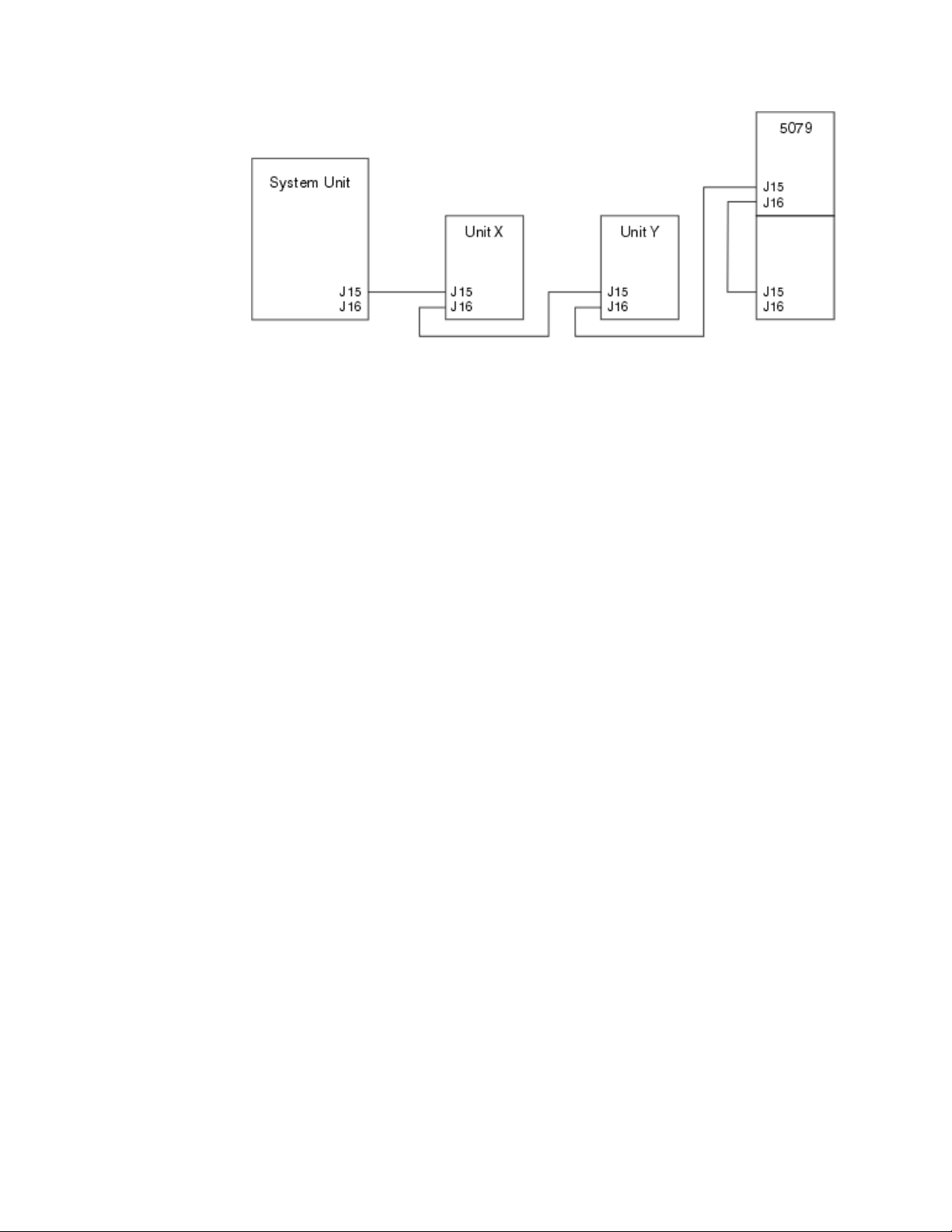
Figure 19. SPCN connections
__ 1. Open the back cover on your 5079. See Appendix A, “Removing the back
covers” on page 31 if you need instructions.
__ 2. Connect the cables to 5079–002 (the upper unit). See Appendix B,
“Connector Locations” on page 35 if you need information about finding
connectors.
__ a. Connect a new HSL cable to HSL connector 0.
__ b. Connect a new HSL cable to HSL connector 1. If you have different
length cables, this cable should be the shortest one.
__ c. Connect a new SPCN cable to connector J15.
__ d. Connect a new SPCN cable to connector J16.
__ e. Connect the power cable. Do not plug into the wall outlet. If your
power cables for the 5079 are two different lengths, connect the
longer cable to 5079–002.
__ 3. Connect the cables to the 5079–001 (the lower unit).
__ a. Connect the HSL cable that you installed in step 2b to HSL
connector 0.
__ b. Connect the SPCN cable that you installed in step 2d to connector
J15.
__ c. Connect the power cable. Do not plug into the wall outlet. If your
power cables for the 5079 are two different lengths, connect the
shorter cable to 5079–001.
__ 4. Remove or open the back cover on your system unit.
__ 5. Remove or open the back cover on unit Y.
__ 6. At unit Y, remove the HSL cable at connector 1. This cable currently runs
between unit Y and your system unit.
__ 7. Connect the HSL cable from your system unit to the HSL connector 1 on
5079–001.
__ 8. Connect the HSL cable from 5079–002 HSL connector 0 to HSL connector 1
on unit Y.
__ 9. Connect the SPCN cable from 5079–002 connector J15 to connector J16 on
unit Y.
__ 10. Install or close the covers on unit Y, your 5079, and your system unit.
__ 11. Go to Chapter 5, “Completing your installation” on page 27.
26 Setting up your 0578, 5074, 5078 or 5079 Expansion Unit V5R2
Page 37

Chapter 5. Completing your installation
Perform the following steps to return complete your installation:
__ 1. Make sure that you have reinstalled all of the covers on the following
system components:
__ a. iSeries system unit.
__ b. All system expansion units.
DANGER
An electrical outlet that is not correctly wired could place hazardous voltage
on metal parts of the system or the products that attach to the system. It is the
customer’s responsibility to ensure that the outlet is correctly wired and
grounded to prevent an electrical shock. (RSFTD201)
Note: The fans may start, and system reference codes will appear when you plug
the power cord for your system unit. These actions are normal. They do not
indicate that your system unit is performing an initial program load (IPL).
__ 2. Plug the power cords for the following system components into electrical
outlets:
__ a. Your system unit.
__ b. All expansion units attached to the system.
__ c. The system unit console.
__ d. The system printer.
__ 3. Turn power on to each of the following system components by using the
associated power-on button:
__ a. The system printer (if present).
__ b. The system control console.
__ 4. Look at the Function/Data display on the control panel. See Appendix C,
“System unit control panel” on page 43 if you need information about your
control panel.
__ 5. Does 01 B V=S appear in the Function/Data display and OK is illuminated?
Note: If you are using Operations Console remote control panel, it may be
necessary to click Enter to verify IPL speed.
Yes N o
↓ Do the following:
__ a. Press the Mode Select button until the Manual indicator (a
small hand) lights up.
__ b. Press the Increment/Decrement push button until 02 appears
in the Function/Data display.
__ c. Press the Enter push button on the control panel.
__ d. Press the Increment/Decrement push button until B appears
in the Function/Data display.
__ e. Press the Enter push button on the control panel.
__ f. Press the Increment/Decrement push button until S appears in
the Function/Data display
© Copyright IBM Corp. 2000, 2002 27
Page 38

__ g. Press the Enter push button on the control panel.
__ h. Press the Mode Select button until the Normal indicator (OK)
lights up.
__ i. Press the Increment/Decrement push button until 01 appears
in the Function/Data display.
__ j. Press the Enter push button on the control panel.
01BSshould appear in the Function/Data display and OK is
illuminated. If it does not, repeat steps 5a on page 27 through
5i.
__ k. Go to step 6.
__ 6. Power on your system unit by pushing the white power-on button.
Note: The time needed to do a complete IPL varies depending on iSeries
model and configuration.
__ 7. Sign on your system unit. Ensure that you have service tools authority.
__ 8. Go to Chapter 6, “Verifying Your New Configuration” on page 29.
28 Setting up your 0578, 5074, 5078 or 5079 Expansion Unit V5R2
Page 39

Chapter 6. Verifying Your New Configuration
Verify your new configuration by performing the following:
__ 1. Type strsst on the command line. Press Enter.
__ 2. Type your service tools userid and service tools password on the
System Service Tools (SST) Sign On display.
Press Enter.
__ 3. Select Start a service tool from the Start a Service Tools display and press
Enter.
__ 4. Select Hardware service manager on the Start a Service Tool display.
Press Enter.
__ 5. Select Packaging hardware resources (system, frames, cards...) on the
Hardware Service Manager display.
Press Enter.
Your new 0578, 5074, 5078 or 5079 expansion unit appears on the list.
Record the Frame ID and Resource name here:___________ , ___________. If
your expansion unit does not appear, you need to verify your installation
by performing these steps:
__ a. Make sure that you powered on your expansion unit.
__ b. Make sure that you installed the cables correctly. Refer to Chapter 2,
“Setting up your 5074 expansion unit” on page 9, Chapter 3, “Setting
up your 0578 expansion unit” on page 15 or Chapter 4, “Setting up
your 5079 Expansion Unit” on page 19.
__ 6. You can verify vital product data (VPD) for your new expansion unit:
__ a. Press F3 to return to the Hardware Service Manager display.
__ b. At the Hardware Service Manager display, select System power
control network (SPCN).
__ c. Press the Enter key twice.
__ d. To update VPD data, do the following:
1) If you installed a 5079, you need to find the Frame ID for both
5079–002 and 5079–001 and the system Serial Number.
2) You can also find the Frame ID by looking at the display on the
expansion unit. For example, if the Frame ID for your 5079–002
(the upper unit) is 4, a *04 will appear on the display.
__ e. Enter a 3 (Write VPD) for your expansion unit. Press Enter.
Example: If the Frame ID for your expansion unit is 2, enter option 3,asis
shown in the example below. Use the Frame ID with a 0 in the
Unit field.
© Copyright IBM Corp. 2000, 2002 29
Page 40

System Power Control Network
Battery capacity test.......:Enabled
Type options, press Enter.
3=Write VPD 5=Display detail 6=Display trace log
7=Test battery interface
Opt Frame Unit Type Number Fault
01 0 00-00000 No
01 1 00-00000 No
03 0 .... 00-00000 No
03 1 .... 00-00000 No
3 02 0 .... 00-00000 No
02 1 .... 00-00000 No
Serial
__ f. At the Write Vital Product Data (VPD) display enter the following
information:
__ 1) At the Type field enter 0578, 5074. 5078 or 5079.
__ 2) At the Model field, enter 001. If you have a 5079, enter 001 for
5079–001 (the lower unit) or 002 for the 5079–002 (the upper
unit).
__ 3) Enter the serial number at the Serial Number field (located on
the central panel label).
__ g. Press the Enter Key.
The message: Vital product data has been successfully written
appears.
__ 7. Press F3 to return to the Hardware Service Manager display.
__ 8. From the Hardware Service Manager display press F6 (print the
configuration) to print the configuration list.
__ 9. For future reference place the configuration list in this book.
__ 10. To return to the Main menu, press F3 (Exit) two times and press the Enter
key.
30 Setting up your 0578, 5074, 5078 or 5079 Expansion Unit V5R2
Page 41

Appendix A. Removing the back covers
5075 and 820 back cover
Remove the back cover for the system unit by gripping the upper corners of the
cover and pulling it up and toward you.
Figure 20. Removing the 5075 and 820 back cover
5074, 830 and 890 back cover
1. Use the latch shown at A to open the back cover on your expansion unit.
2. If needed, use the latch shown at B to remove the back cover.
Note: The 5074 and 830 back covers do not look the same. However, the procedure
to open them is the same.
© Copyright IBM Corp. 2000, 2002 31
Page 42

Figure 21. Removing the 5074 and 830 back cover
5079 and 840 back cover
Open the back cover on your 5079 by pressing the latch at A.
32 Setting up your 0578, 5074, 5078 or 5079 Expansion Unit V5R2
Page 43

Figure 22. Opening the 5079 and 840 back cover
Appendix A. Removing the back covers 33
Page 44

Accessing units in a rack
1. Move to the back of the rack, press latch A, and open the back door of the
rack.
34 Setting up your 0578, 5074, 5078 or 5079 Expansion Unit V5R2
Page 45

Appendix B. Connector Locations
820 HSL connector locations
Figure 23. 820 HSL connector locations
© Copyright IBM Corp. 2000, 2002 35
Page 46

830 HSL connector locations
Figure 24. 830 HSL connector locations
36 Setting up your 0578, 5074, 5078 or 5079 Expansion Unit V5R2
Page 47

840 HSL connector locations
Figure 25. 840 HSL connector locations
Appendix B. Connector Locations 37
Page 48

890 HSL connector locations
Figure 26. 890 HSL connector locations
38 Setting up your 0578, 5074, 5078 or 5079 Expansion Unit V5R2
Page 49

5079 connector locations
Figure 27. 5079 connector locations
Appendix B. Connector Locations 39
Page 50

5074 connector locations
Figure 28. 5074 connector locations
40 Setting up your 0578, 5074, 5078 or 5079 Expansion Unit V5R2
Page 51

5075 connector locations
Figure 29. 5075 connector locations
5078 connector locations
Figure 30. 5078 connector locations
Appendix B. Connector Locations 41
Page 52

42 Setting up your 0578, 5074, 5078 or 5079 Expansion Unit V5R2
Page 53

Appendix C. System unit control panel
1. Go to the front of your iSeries system unit. Open the control panel door.
2. Before you can use F Increment/Decrement Buttons and G Enter Push
button, you need to pressH Mode Select to select manual mode K.
You will use the push buttons on the control panel. Familiarize yourself with
the control panel on your unit.
A Power On Light
v A blinking light indicates power to the unit.
v A constant light indicates that the unit is up and working.
B Power Push button
C Processor Activity
D System Attention
E Function/Data Display
F Increment/Decrement Buttons
G Enter Push button
H Mode Select
J Electronic Keystick Slot
K Secure
L Auto
M Normal
N Manual
© Copyright IBM Corp. 2000, 2002 43
Page 54

44 Setting up your 0578, 5074, 5078 or 5079 Expansion Unit V5R2
Page 55

Appendix D. Cabling rules for systems with a migration unit or the 9079 and 9094 expansion unit
If you already have a migration unit or a 9079 Expansion Unit set up on your
system, there are special cabling rules that you must follow. On the table below,
find your system unit and follow the rule that apply to your system unit.
System unit Rule
iSeries 820
iSeries 830
iSeries 840
v A 503x migration unit must be in the first position of the HSL
loop if there are a total of three external units or fewer. The
first position is the position that is closest to connector A0 on
the system unit. See Figure 31 on page 46 and Figure 32 on
page 46.
v If there are four or five external units, the 503x must be in the
second position of the HSL loop. There must be one
expansion unit between A0 and the 503x. See Figure 33 on
page 47 and Figure 34 on page 47.
v The 5079 counts as two independent 5074s. If you have two
5079s and one 503x, follow the cabling diagram that is shown
in Figure 35 on page 47.
v The 503x must be in the last position of the SPCN loop. See
Figure 36 on page 48.
v You cannot install a 5074 or 5079 on the same HSL loop as the
503x or 5077 migration unit. Use the next available HSL
connector.
v The 503x must be in the last position of the SPCN loop. See
Figure 36 on page 48.
v Set up the SPCN cable for your 5074 in the same SPCN loop
as the 5077.
This is true even though you are connecting the 5074 to a
different HSL loop than the 5077.
You can do this by connecting the SPCN cable from J15 of
your new expansion unit to J16 of the 5077.
See Figure 37 on page 48.
v You cannot install a 5074 or 5079 to the same HSL loop as the
5077.
v You can install up to two 5074s or one 5079 with a 9079 on
the first loop (A0 and A1).
v Set up the SPCN cable for your 5074 or 5079 in the same
SPCN loop as the 5077 or 9079.
This is true even though you are connecting the 5074 or 5079
to a different HSL loop than the 5077 or 9079.
You can do this by connecting the SPCN cable from J15 of
your new expansion unit to J16 of the 5077 or 9079.
See Figure 37 on page 48.
© Copyright IBM Corp. 2000, 2002 45
Page 56

System unit Rule
iSeries 890
v You can install up to two 5074s or one 5079 with a 9094 on
the first loop (A0 and A1).
v Set up the SPCN cable for your 5074 or 5079 in the same
SPCN loop as the 9094.
This is true even though you are connecting the 5074 or 5079
to a different HSL loop than the 9094.
You can do this by connecting the SPCN cable from J15 of
your new expansion unit to J16 of the 9094.
See Figure 38 on page 49.
Figure 31. HSL loop with 503x
Figure 32. HSL loop with three external units
46 Setting up your 0578, 5074, 5078 or 5079 Expansion Unit V5R2
Page 57

Figure 33. HSL loop with four external units
Figure 34. HSL loop with five external units
Figure 35. HSL loop with two 5079s and a 503x
Appendix D. Cabling rules for systems with a migration unit or the 9079 and 9094 expansion unit 47
Page 58

Figure 36. SPCN loop with 503x
Figure 37. SPCN and HSL loop with 5077
48 Setting up your 0578, 5074, 5078 or 5079 Expansion Unit V5R2
Page 59

Figure 38. HSL loop with 0578
Appendix D. Cabling rules for systems with a migration unit or the 9079 and 9094 expansion unit 49
Page 60

50 Setting up your 0578, 5074, 5078 or 5079 Expansion Unit V5R2
Page 61

Notices
This information was developed for products and services offered in the U.S.A.
IBM may not offer the products, services, or features discussed in this document in
other countries. Consult your local IBM representative for information on the
products and services currently available in your area. Any reference to an IBM
product, program, or service is not intended to state or imply that only that IBM
product, program, or service may be used. Any functionally equivalent product,
program, or service that does not infringe any IBM intellectual property right may
be used instead. However, it is the user’s responsibility to evaluate and verify the
operation of any non-IBM product, program, or service.
IBM may have patents or pending patent applications covering subject matter
described in this document. The furnishing of this document does not give you
any license to these patents. You can send license inquiries, in writing, to:
IBM Director of Licensing
IBM Corporation
500 Columbus Avenue
Thornwood, NY 10594
U.S.A.
For license inquiries regarding double-byte (DBCS) information, contact the IBM
Intellectual Property Department in your country or send inquiries, in writing, to:
IBM World Trade Asia Corporation
Licensing
2-31 Roppongi 3-chome, Minato-ku
Tokyo 106, Japan
The following paragraph does not apply to the United Kingdom or any other
country where such provisions are inconsistent with local law:
INTERNATIONAL BUSINESS MACHINES CORPORATION PROVIDES THIS
PUBLICATION “AS IS” WITHOUT WARRANTY OF ANY KIND, EITHER
EXPRESS OR IMPLIED, INCLUDING, BUT NOT LIMITED TO, THE IMPLIED
WARRANTIES OF NON-INFRINGEMENT, MERCHANTABILITY OR FITNESS
FOR A PARTICULAR PURPOSE. Some states do not allow disclaimer of express or
implied warranties in certain transactions, therefore, this statement may not apply
to you.
This information could include technical inaccuracies or typographical errors.
Changes are periodically made to the information herein; these changes will be
incorporated in new editions of the publication. IBM may make improvements
and/or changes in the product(s) and/or the program(s) described in this
publication at any time without notice.
Any references in this information to non-IBM Web sites are provided for
convenience only and do not in any manner serve as an endorsement of those Web
sites. The materials at those Web sites are not part of the materials for this IBM
product and use of those Web sites is at your own risk.
Any performance data contained herein was determined in a controlled
environment. Therefore, the results obtained in other operating environments may
vary significantly. Some measurements may have been made on development-level
© Copyright IBM Corp. 2000, 2002 51
Page 62

systems and there is no guarantee that these measurements will be the same on
generally available systems. Furthermore, some measurement may have been
estimated through extrapolation. Actual results may vary. Users of this document
should verify the applicable data for their specific environment.
Information concerning non-IBM products was obtained from the suppliers of
those products, their published announcements or other publicly available sources.
IBM has not tested those products and cannot confirm the accuracy of
performance, compatibility or any other claims related to non-IBM products.
Questions on the capabilities of non-IBM products should be addressed to the
suppliers of those products.
All statements regarding IBM’s future direction or intent are subject to change or
withdrawal without notice, and represent goals and objectives only.
All IBM prices shown are IBM’s suggested retail prices, are current and are subject
to change without notice. Dealer prices may vary.
This information is for planning purposes only. The information herein is subject to
change before the products described become available.
This information contains examples of data and reports used in daily business
operations. To illustrate them as completely as possible, the examples include the
names of individuals, companies, brands, and products. All of these names are
fictitious and any similarity to the names and addresses used by an actual business
enterprise is entirely coincidental.
Trademarks
If you are viewing this information softcopy, the photographs and color
illustrations may not appear.
The drawings and specifications contained herein shall not be reproduced in whole
or in part without the written permission of IBM.
IBM has prepared this publication for use by hardware service representatives in
the maintenance or repair of the specific machines indicated. IBM makes no
representations that it is suitable for any other purpose.
The drawings and specifications contained herein shall not be reproduced in whole
or in part without the written permission of IBM.
IBM has prepared this publication for use by customer personnel for operating and
planning for the specific machines indicated. IBM makes no representations that it
is suitable for any other purpose.
The following terms are trademarks of International Business Machines
Corporation in the United States, or other countries, or both:
Application System/400
AS/400
IBM
Operating System/400
OS/400
400
52 Setting up your 0578, 5074, 5078 or 5079 Expansion Unit V5R2
Page 63

C-bus is a trademark of Corollary, Inc. in the United States, other countries, or
both.
Java and all Java-based trademarks are trademarks of Sun Microsystems, Inc. in the
United States, other countries, or both.
Microsoft, Windows, Windows NT, and the Windows logo are trademarks of
Microsoft Corporation in the United States, other countries, or both.
PC Direct is a trademark of Ziff Communications Company in the United States,
other countries, or both and is used by IBM Corporation under license.
ActionMedia, LANDesk, MMX, Pentium, and ProShare are trademarks of Intel
Corporation in the United States, other countries, or both.
UNIX is a registered trademark in the United States and other countries licensed
exclusively through The Open Group.
SET and the SET Logo are trademarks owned by SET Secure Electronic Transaction
LLC.
Other company, product, and service names may be trademarks or service marks
of others.
Electronic Emission Notices
Federal Communications Commission (FCC) Statement
Note: This equipment has been tested and found to comply with the limits for a
Class A digital device, pursuant to Part 15 of the FCC Rules. These limits are
designed to provide reasonable protection against harmful interference when the
equipment is operated in a commercial environment. This equipment generates,
uses, and can radiate radio frequency energy and, if not installed and used in
accordance with the instruction manual, may cause harmful interference to radio
communications. Operation of this equipment in a residential area is likely to cause
harmful interference, in which case the user will be required to correct the
interference at his own expense.
Properly shielded and grounded cables and connectors must be used in order to
meet FCC emission limits. IBM is not responsible for any radio or television
interference caused by using other than recommended cables and connectors or by
unauthorized changes or modifications to this equipment. Unauthorized changes
or modifications could void the user’s authority to operate the equipment.
This device complies with Part 15 of the FCC rules. Operation is subject to the
following two conditions: (1) this device may not cause harmful interference, and
(2) this device must accept any interference received, including interference that
may cause undesired operation.
Responsible Party:
International Business Machines Corporation
New Orchard Road
Armonk, NY 10504
Telephone: 1-919-543-2193
Notices 53
Page 64

Industry Canada Compliance Statement
This Class A digital apparatus meets the requirements of the Canadian
Interference-Causing Equipment Regulations.
Avis de conformitéàla réglementation d’Industrie Canada
Cet appareil numérique de la classe A respecte toutes les exigences du Règlement
sur le matériel brouilleur du Canada.
European Community Compliance Statement
This product is in conformity with the protection requirements of EU Council
Directive 89/336/EEC on the approximation of the laws of the Member States
relating to electromagnetic compatibility. IBM cannot accept responsibility for any
failure to satisfy the protection requirements resulting from a non-recommended
modification of the product, including the fitting of non-IBM option cards.
Australia and New Zealand Class A Statement
Attention: This is a Class A product. In a domestic environment this product may
cause radio interference in which case the user may be required to take adequate
measures.
Electronic Emission Notices
The following Statement applies to this IBM product. The statement for other IBM
products intended for use with this product will appear in their accompanying
manuals.
Federal Communications Commission (FCC) Statement
Note: This equipment has been tested and found to comply with the limits for a
class B digital devices, pursuant to Part 15 of the FCC Rules. These limits are
designed to provide reasonable protection against harmful interference in a
residential installation. This equipment generates, uses, and can radiate radio
frequency energy and, if not installed and used in accordance with the instructions,
may cause harmful interference to radio communications. However, there is no
guarantee that interference will not occur in a particular installation. If this
equipment does cause harmful interference to radio or television reception, which
can be determined by turning the equipment off and on, the user is encouraged to
try to correct the interference by one or more of the following measures:
v Reorient or relocate the receiving antenna.
v Increase the separation between the equipment and receiver.
v Connect the equipment into an outlet on a circuit different from that to which
the receiver is connected.
v Consult an IBM authorized dealer or service representative for help.
Properly shielded and grounded cables and connectors must be used in order to
meet FCC emission limits. Proper cables and connectors are available from IBM
authorized dealers. IBM is not responsible for any radio or television interference
caused by using other than recommended cables or connectors or by unauthorized
changes or modifications to this equipment. Unauthorized changes or
modifications could void the user’s authority to operate the equipment.
54 Setting up your 0578, 5074, 5078 or 5079 Expansion Unit V5R2
Page 65

This device complies with Part 15 of the FCC Rules. Operation is subject to the
following two conditions: (1) this device may not cause harmful interferences, and
(2) this device must accept any interferences received, including interference that
may cause undesired operation.
Responsible Party:
International Business Machines Corporation
New Orchard Road
Armonk, NY 10504
Telephone: 1-919-543-2193
Industry Canada Compliance Statement
This Class B digital apparatus meets the requirements of the Canadian
Interference-Causing Equipment Regulations.
Avis de conformitéàla réglementation d’Industrie Canada
Cet appareil numérique de la classe B respecte toutes les exigences du Réglement
sur le matériel brouilleur du Canada.
European Community Compliance Statement
This product is in conformity with the protection requirements of EC Council
Directive 89/336/EEC on the approximation of the laws of the Member States
relating to electromagnetic compatibility. IBM cannot accept responsibility for any
failure to satisfy the protection requirements resulting from a non-recommended
modification of the product, including the fitting of non-IBM option cards.
This product has been tested and found to comply with the limits for Class B
Information Technology Equipment according to CISPR 22 / European Standard
EN 55022. The limits for Class B equipment were derived for typical residential
environments to provide reasonable protection against interference with licensed
communication devices.
Properly shielded and grounded cables and connectors (IBM part number 75G5958
or its equivalent) must be used in order to reduce the potential for causing
interference to radio and TV communications and to other electrical or electronic
equipment. Such cables and connectors are available from IBM authorized dealers.
IBM cannot accept responsibility for an interference caused by using other than
recommended cables and connectors.
Notices 55
Page 66

56 Setting up your 0578, 5074, 5078 or 5079 Expansion Unit V5R2
Page 67

Readers’ Comments — We’d Like to Hear from You
iSeries
Setting Up Your
0578, 5074, 5078 or 5079
Expansion Unit
Version 5
Publication No. SA41-5149-02
Overall, how satisfied are you with the information in this book?
Very Satisfied Satisfied Neutral Dissatisfied Very
Dissatisfied
Overall satisfaction hhhhh
How satisfied are you that the information in this book is:
Very Satisfied Satisfied Neutral Dissatisfied Very
Dissatisfied
Accurate hhhhh
Complete hhhhh
Easy to find hhhhh
Easy to understand hhhhh
Well organized hhhhh
Applicable to your tasks hhhhh
Please tell us how we can improve this book:
Thank you for your responses. May we contact you? h Yes h No
When you send comments to IBM, you grant IBM a nonexclusive right to use or distribute your comments in any
way it believes appropriate without incurring any obligation to you.
Name Address
Company or Organization
Phone No.
Page 68

___________________________________________________________________________________________________
Readers’ Comments — We’d Like to Hear from You
SA41-5149-02
_________________________________________________________________________________________
Fold and Tape Please do not staple Fold and Tape
NO POSTAGE
NECESSARY
IF MAILED IN THE
UNITED STATES
Cut or Fold
Along Line
BUSINESS REPLY MAIL
FIRST-CLASS MAIL PERMIT NO. 40 ARMONK, NEW YORK
POSTAGE WILL BE PAID BY ADDRESSEE
IBM CORPORATION
ATTN DEPT 542 IDCLERK
3605 HWY 52 N
ROCHESTER MN 55901-7829
_________________________________________________________________________________________
Fold and Tape Please do not staple Fold and Tape
SA41-5149-02
Cut or Fold
Along Line
Page 69

Page 70

Printed in U.S.A.
SA41-5149-02
 Loading...