

Page 1

AS/400e
Setting Up Your 5065 or 5066 Expansion
Unit
Ve r s i o n 4
SA41-5146-01
Page 2

Page 3

AS/400e
Setting Up Your 5065 or 5066 Expansion
Unit
Ve r s i o n 4
SA41-5146-01
Page 4

Note
Before using this information and the product it supports, be sure to read the information in “Safety and Environmental
Notices” on page v and “Notices” on page 65.
Second Edition (March 2000)
This edition applies to version 1, release 1 of the 5065 Expansion Unit and version 1, release 1 of the 5066
Expansion Unit (SA41–5146–01) and to all subsequent releases and modifications until otherwise indicated in new
editions. This edition applies only to reduced instruction set computer (RISC) systems.
This edition replaces SA41–5146–00. This edition applies only to reduced instruction set computer (RISC) systems.
© Copyright International Business Machines Corporation 1999, 2000. All rights reserved.
US Government Users Restricted Rights – Use, duplication or disclosure restricted by GSA ADP Schedule Contract
with IBM Corp.
Page 5

Contents
Safety and Environmental Notices . . . v
Danger Notices .............v
Caution Notices .............v
Laser Safety Information .........vi
Product Recycling and Disposal.......vi
Battery Return Program .........vi
Environmental Design ..........vi
About setting up the 5065 or 5066
Expansion Unit (SA41–5146–01) ....ix
Prerequisite and related information ......ix
How to send us your comments ........x
Chapter 1. Preparing to set up your 5065
or 5066 ...............1
Hardwarerequirements...........1
Site planning considerations for the 5066 .....1
Planning your cable layout .........2
Handling optical cables ...........4
Powering down your AS/400 system unit ....5
Chapter 2. Setting up your 5065
Expansion Unit............7
Connecting your 5065 directly to your AS/400e
system unit ...............7
Connecting the cables to your 5065 Expansion
Unit................7
Connecting the cables to your AS/400 system
unit................10
Connecting your 5065 Expansion Unit in a loop . . 12
Updating Vital Product Data ........25
Appendix A. Connecting cables to your
AS400e System 620 or S20 ......27
Removing the access cover for the AS/400e system
620 or server S20 ............27
Connecting the SPCN and optical cables to the
AS/400e system 620 or server S20 .......31
Replacing the covers on your AS/400e system 620
or server S20 ..............32
Appendix B. Possible configurations
with other expansion units ......35
Appendix C. Installing disk units in the
5065 or 5066 Expansion Unit .....37
Optimizing your new disk unit ........37
Installing a disk unit ...........38
Concurrent procedure (system-unit powered on) 41
Nonconcurrent procedure (system-unit powered
off)................47
Appendix D. Installing removable
media devices in the 5065 Expansion
Unit ................55
Installing removable media devices ......56
Concurrent procedure (system-unit powered on) 58
NonConcurrent procedure (system-unit powered
off)................61
Chapter 3. Setting up your 5066
Expansion Unit ...........17
Openingthecovers............17
Locating 5066 connectors ..........19
Connecting your 5066 to your system unit ....19
Chapter 4. Completing your installation 23
Notices ..............65
Electronic Emission Notices .........66
Federal Communications Commission (FCC)
Statement..............66
Trademarks..............67
Readers’ Comments — We’d Like to
Hear from You ...........69
Chapter 5. Verifying Your New
Configuration ............25
© Copyright IBM Corp. 1999, 2000 iii
Page 6

iv Setting Up Your 5065 or 5066 Expansion Unit V4R5
Page 7

Safety and Environmental Notices
Danger Notices
A danger notice calls attention to a situation that is potentially lethal or extremely
hazardous to people.
DANGER
An electrical outlet that is not correctly wired could place hazardous voltage
on metal parts of the system or the products that attach to the system. It is the
customer’s responsibility to ensure that the outlet is correctly wired and
grounded to prevent an electrical shock. (RSFTD201)
DANGER
To prevent a possible electrical shock when installing the system, ensure that
the power cords for all devices are unplugged before installing signal cables.
(RSFTD202)
DANGER
To prevent a possible electrical shock when adding or removing any devices
to or from the system, ensure that the power cords for those devices are
unplugged before the signal cables are connected or disconnected. If possible,
disconnect all power cords from the existing system before you add or
remove a device. (RSFTD203)
Caution Notices
DANGER
To prevent a possible electrical shock during an electrical storm, do not
connect or disconnect cables or station protectors for communications lines,
display stations, printers, or telephones. (RSFTD003)
DANGER
To prevent a possible electrical shock from touching two surfaces with
different electrical grounds, use one hand, when possible, to connect or
disconnect signal cables. (RSFTD004)
A caution notice calls attention to a situation that is potentially hazardous to
people because of some existing condition.
CAUTION:
Telecommunications Statement: This unit contains over-voltage circuits between
the ac power outlet and the unit. These circuits meet the standard limits
described in International Electrical Commission (IEC) 664, installation category
II. It is the customer’s responsibility to ensure that the power outlet meets the
standards of IEC 664, installation category II. (RSFTC214)
© Copyright IBM Corp. 1999, 2000 v
Page 8

CAUTION:
Your IBM equipment is heavy. Never attempt to lift or move any system
equipment without help. (RSFTC202)
Laser Compliance
All Lasers are certified in the U.S. to conform to the requirements of DHHS 21 CFR
Subchapter J for class 1 laser products. Outside the U.S., they are certified to be in
compliance with the IEC 825 (first edition 1984) and as a class 1 laser product.
Consult the label on each part for laser certification numbers and approval
information.
Laser Safety Information
CAUTION:
This product may contain a CD-ROM which is a class 1 laser product.
(RSFTC240)
CAUTION:
All IBM laser modules are designed so that there is never any human access to
laser radiation above a class 1 level during normal operation, user maintenance,
or prescribed service conditions. Data processing environments can contain
equipment transmitting on system links with laser modules that operate at
greater than class 1 power levels. For this reason, never look into the end of an
optical fiber cable or open receptacle. Only trained service personnel should
perform the inspection or repair of optical fiber cable assemblies and
receptacles. (RSFTC243)
Product Recycling and Disposal
Components of the system, such as structural parts and circuit cards, can be
recycled where recycling facilities exist. IBM does not currently collect and recycle
used IBM products from customers in the United States other than those products
that are involved in trade-in programs. Companies are available to disassemble,
reutilize, recycle, or dispose of electronic products. Contact an IBM account
representative for more information.
The system unit contains batteries and circuit boards with lead solder. Before you
dispose of this unit, these batteries and circuit boards must be removed and
discarded according to local regulations or recycled where facilities exist. This book
contains specific information on each battery type where applicable.
Battery Return Program
In the United States, IBM has established a collection process for reuse, recycling,
or proper disposal of used IBM batteries and battery packs. For information on
proper disposal of the batteries in this unit, please contact IBM at 1-800-426-4333.
Please have the IBM part number that is listed on the battery available when you
make your call. For information on battery disposal outside the United States,
contact your local waste disposal facility.
Environmental Design
The environmental efforts that have gone into the design of the system signify
IBM’s commitment to improve the quality of its products and processes. Some of
these accomplishments include the elimination of the use of Class I
ozone-depleting chemicals in the manufacturing process, reductions in
vi Setting Up Your 5065 or 5066 Expansion Unit V4R5
Page 9

manufacturing wastes, and increased product energy efficiency. For more
information, contact an IBM account representative.
CAUTION:
The optical link card contains a laser. To avoid the release of toxic substances
into the environment, do not burn. Discard the optical link as instructed by local
regulations. (RSFTC236)
Safety and Environmental Notices vii
Page 10

viii Setting Up Your 5065 or 5066 Expansion Unit V4R5
Page 11

About setting up the 5065 or 5066 Expansion Unit
(SA41–5146–01)
This book contains information about setting up the 5065 Expansion Unit or 5066
Expansion Unit. You may install new expansion unit yourself. It will take
approximately one to three hours to install the hardware.
You also may elect not to install the expansion unit yourself. Contact IBM
Authorized Dealer to make arrangements for them to install the expansion unit for
a fee.
If you would like IBM to plan your installation, you may do one of the following:
v Call 1-800-IBM-4YOU.
®
v Call the AS/400
v Request a FAX by dialing 1-800-426-4329. Select document 1866.
v Contact IBM for the Optimizing Your Business Investment, Installation Planning,
G325-6313, brochure.
The following list is an overview for installing your new expansion unit.
v Preparing for your installation.
v Power down your AS/400 system unit.
v Connecting cables to your expansion unit.
v Connecting cables from your expansion unit to your AS/400 system unit (or
AS/400 expansion unit).
v Powering up your AS/400 system unit and your expansion unit.
v Verifying your new configuration.
Direct support line at 1-800-274-0015.
®
or an
Prerequisite and related information
You can find AS/400 System information at the following web site:
http://www.as400.ibm.com
From the Technical Studio link, you can find the relevant information such as the
AS/400 Site Preparation Guide.
Use the AS/400 Information Center as your starting point for looking up AS/400
technical information. You can access the Information Center from the AS/400e
Information Center CD-ROM (English version: SK3T-2027) or from one of these
Web sites:
http://www.as400.ibm.com/infocenter
http://publib.boulder.ibm.com/pubs/html/as400/infocenter.htm
The AS/400 Information Center contains important topics such as logical
partitioning, clustering, Java
™
, TCP/IP, Web serving, and secured networks. It also
contains Internet links to Web sites such as the AS/400 Online Library and the
AS/400 Technical Studio. Included in the Information Center is a link that
describes at a high level the differences in information between the Information
Center and the Online Library.
© Copyright IBM Corp. 1999, 2000 ix
™
Page 12

How to send us your comments
Your feedback is important in helping to provide the most accurate and
high-quality information. If you have any comments about this book or any other
AS/400 documentation, fill out the readers’ comment form at the back of this
book.
v If you prefer to send comments by mail, use the readers’ comment form with the
address that is printed on the back. If you are mailing a reader’s comment form
from a country other than the United States, you can give the form to the local
IBM branch office or IBM representative for postage-paid mailing.
v If you prefer to send comments by FAX, use either of the following numbers:
– United States and Canada: 1-800-937-3430
– Other countries: 1-507-253-5192
v If you prefer to send comments electronically, use one of these e-mail addresses:
– Comments on books:
RCHCLERK@us.ibm.com
IBMMAIL, to IBMMAIL(USIB56RZ)
– Comments on the AS/400 Information Center:
RCHINFOC@us.ibm.com
Be sure to include the following:
v The name of the book.
v The publication number of the book.
v The page number or topic to which your comment applies.
x Setting Up Your 5065 or 5066 Expansion Unit V4R5
Page 13

Chapter 1. Preparing to set up your 5065 or 5066
This chapter explains what you need to do before you install your 5065 or 5066
Expansion Unit. This includes the following tasks:
1. Unpack your expansion unit (refer to the instructions for unpacking that came
with your expansion unit).
2. Plan layouts for your cables.
3. Power down your system unit.
Before you begin the installation process, you should carefully plan where you will
install your new expansion unit. You should consider several factors that include
size, weight, security, and environmental factors. IBM provides detailed
information for AS/400 planning at the following web site:
http://www.as400.ibm.com
You can find the AS/400 Site Preparation Guide and other relevant information by
selecting the Technical Studio under Hot Topics at this web site.
Hardware requirements
When you ordered your new expansion unit, the configurator took an inventory of
your system. The configurator then determined if you needed to add an optical
card or an SPCN card.
If you received these features in your new expansion unit package, contact IBM or
an Authorized Dealer to make arrangements to have them installed.
5065 Hardware Requirements
If you are installing your 5065 Expansion Unit directly to your system unit, you
need to have these prerequisites:
v An available system power control network (SPCN) connector.
v An available 2688 optical link processor (OLP) card (one OLP card can support
two expansion units).
If you are connecting your 5065 Expansion Unit to another expansion unit, your
expansion unit needs to have:
v An available SPCN connector.
v An available 2682 OLP card.
5066 Hardware Requirements
You need to have the following prerequisites to install your 5066 Expansion Unit:
v An available system power control network (SPCN) connector.
v An available 2688 optical link processor (OLP) card (one OLP card can support
both expansion units in your 5066).
Site planning considerations for the 5066
Weight and Size of the 5066
© Copyright IBM Corp. 1999, 2000 1
Page 14

Table 1 shows the weight and dimensions of the 5066 Expansion Unit.
Table 1. 5066 Weight and Size descriptions
Weight (fully configured) 1600 lb (725 kg)
Width 25.5 in (650 mm)
Depth 40 in (1020 mm)
Height 71 in (1800 mm)
The 5066 has a floor loading of 86 lb/ft2(420 kg/m2). Because of the size and
weight of the 5066, you should do the following:
CAUTION:
Overlapping the clearance defined below with adjacent equipment results in a
significant increase in the amount of floor loading.
v Contact your facility or structural engineer to determine a safe site for your
5066.
v Leave 30 in. (762 mm) of clearance to the front and back of the 5066.
v Leave 5 in. (127 mm) of clearance to the left and right of the 5066.
Planning your cable layout
When you decide where to place your cables, follow your site plan and keep the
following things in mind:
v Avoid creating a safety hazard.
v Avoid damaging the cable.
Placing power cords for the 5066
You need to provide the appropriate receptacles for the power cords shipped with
your 5066. The usable length of the upper power cord is 4 ft. (1.2 m) shorter than
the length of the lower power cord.
Redundant links
Your new expansion unit has disk units. Therefore, when you plan your cable
layout, you should use a redundant link configuration to protect your disk units. A
redundant link is a secondary optical cable link that your system can use if the
primary link experiences a failure. You can create a redundant link configuration
by connecting an extra optical cable link between the expansion units and the
system unit.
Refer to Figure 1 on page 3 to see how to plan your cables with a redundant link
configuration with one expansion unit. If you are linking two expansion units refer
to Figure 2 on page 3 If you are setting up a 5066, refer to Figure 3 on page 4.
2 Setting Up Your 5065 or 5066 Expansion Unit V4R5
Page 15
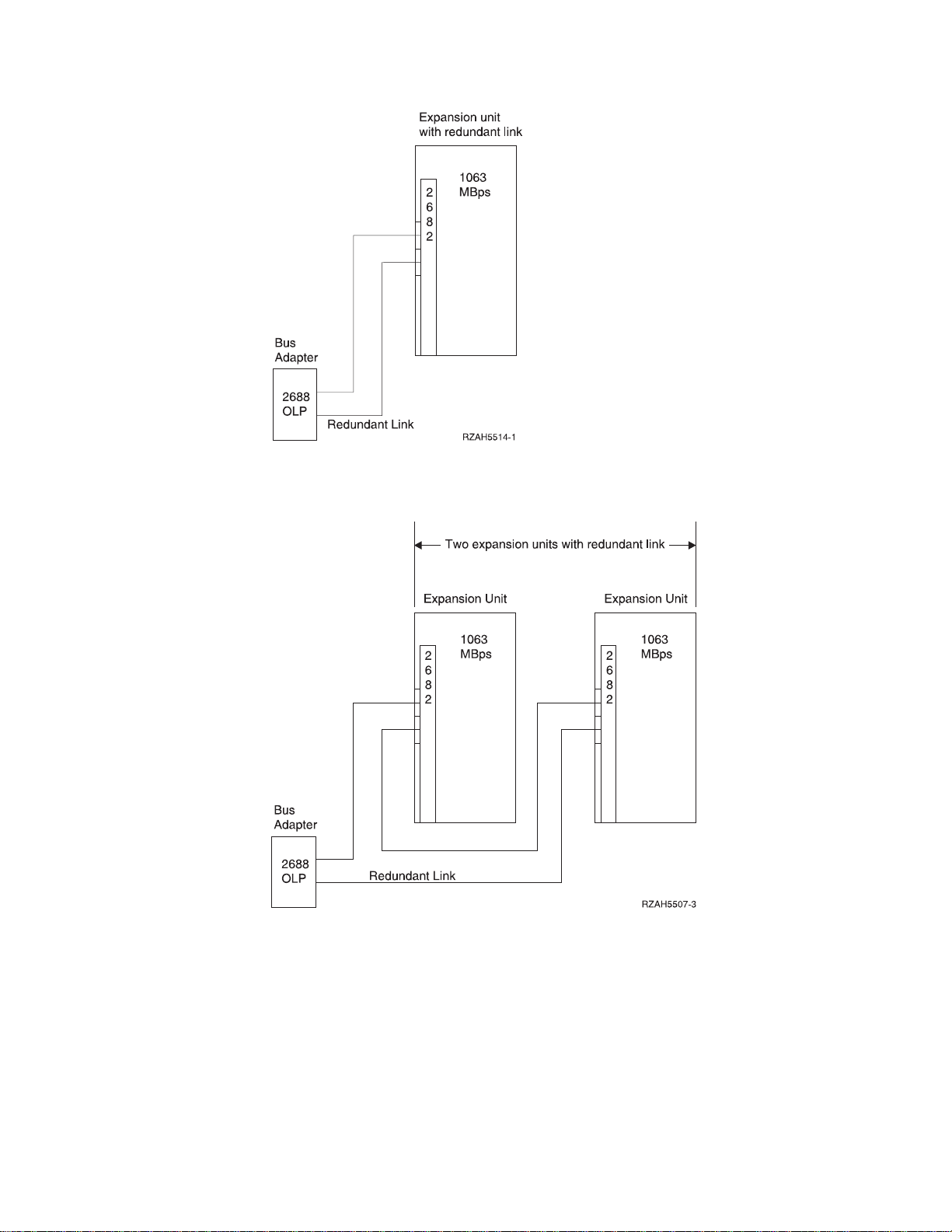
Figure 1. Planning for redundant link one expansion unit
Figure 2. Planning for redundant link with two expansion units
Chapter 1. Preparing to set up your 5065 or 5066 3
Page 16
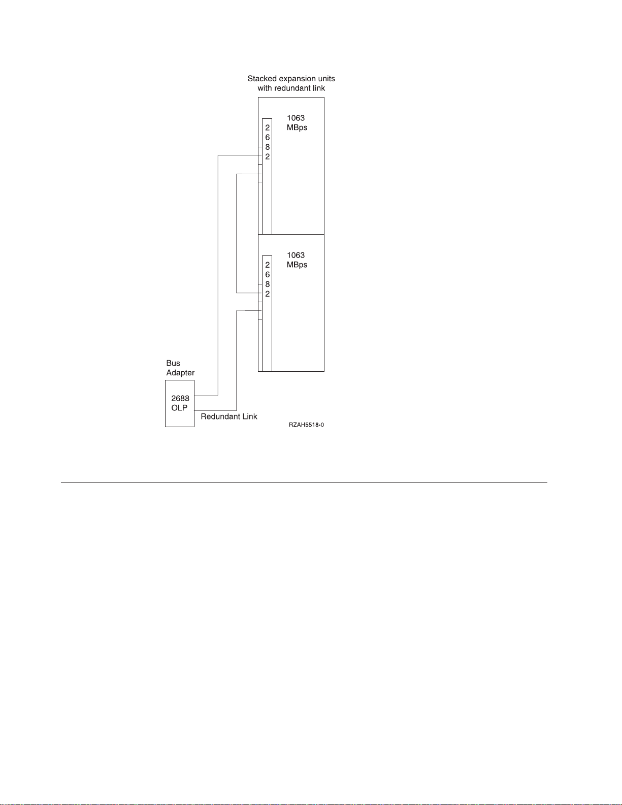
Figure 3. Planning for redundant link with stacked expansion units (5066)
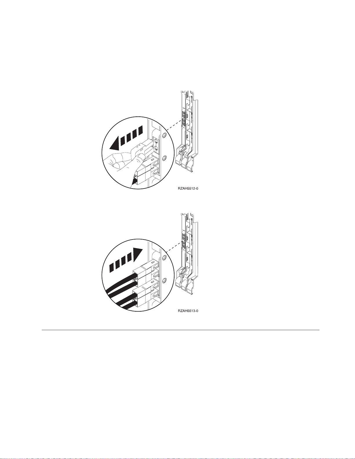
Handling optical cables
When you handle optical cables, remember to observe these guidelines.
Attention:
v Handle the optical cables with care to prevent damage.
v Do not use pliers or similar tools to hold an optical bus cable.
v Do not use the cable to disconnect the cable connector.
v Refer to Figure 4 on page 5 before disconnecting cables.
v Do not place the cables near any sharp edges or points that could cut the outer
covering.
v Do not place the cables near any objects that are very hot or very cold.
v Do not coil the cables to a diameter less than 16.0 cm (6.3 inches).
v Do not bend the cables to a radius less than 3.0 cm (1.2 inches).
v Do not grip the optical cables with mechanical tools.
v Do not remove the dust covers from the connectors until you are ready to clean
the connectors and attach the cables.
v If the dust caps have been in place, IBM recommends that you clean the
connectors before attaching them.
4 Setting Up Your 5065 or 5066 Expansion Unit V4R5
Page 17
If you need to clean the connectors, follow the instructions in the Fiber Optic
Cleaning Kit (IBM part 5453521).
v Use care when you connect the cables to prevent damage to the housing or to
the end of the fiber-optical cable.
v Refer to Figure 5 when installing a cable.
Figure 4. Removing an optical cable
Figure 5. Installing an optical cable
Powering down your AS/400 system unit
You need to power down your AS/400 system unit before you can connect your
new expansion unit to it. Follow the steps below to power down your system unit.
__ 1. Ensure that you have a current backup of your operating system and
licensed programs. If you have backed up the operating system and licensed
programs since the last time you applied PTFs, that backup is acceptable.
__ 2. If you have installed logical partitions on your system unit, refer to the
AS/400 Information Center. At the AS/400 Information Center you can find
instructions on powering down a system with logical partitions.
__ 3. Ensure that all jobs are complete.
__ 4. When all jobs are complete, type pwrdwnsys *immed on an AS/400 command
line and press the Enter key.
Chapter 1. Preparing to set up your 5065 or 5066 5
Page 18

Note: If you encounter difficulties during the installation, contact your authorized
dealer or service provider.
__ 5. After your system unit has completely powered down, power off all PCs
and devices, such as printers and display stations, that are connected to the
system unit.
__ 6. Unplug any power cords, such as for printers and display stations, that are
connected to the system unit.
__ 7. Unplug the power cord for the system unit from the electrical outlet.
If you are setting up a 5065 Expansion Unit, go to “Chapter 2. Setting up your 5065
Expansion Unit” on page 7. If you are setting up a 5066 Expansion Unit, go to
“Chapter 3. Setting up your 5066 Expansion Unit” on page 17
6 Setting Up Your 5065 or 5066 Expansion Unit V4R5
Page 19

Chapter 2. Setting up your 5065 Expansion Unit
RV2D094-0
This chapter explains how to set up your 5065 Expansion Unit. This chapter has
two sets of directions:
v “Connecting your 5065 directly to your AS/400e system unit”.
v “Connecting your 5065 Expansion Unit in a loop” on page 12.
Follow the direction that best fits your configuration.
Connecting your 5065 directly to your AS/400e system unit
Connecting your 5065 directly to your system unit consists of two major steps:
1. Connecting cables to your 5065 Expansion unit.
2. Connecting cables to your system unit.
Connecting the cables to your 5065 Expansion Unit
Use the following steps to install the SPCN cables and optical cables to the 5065
Expansion Unit.
__ 1. Find the sheet of labels for the optical cables in the information shipped
with your expansion unit. (Make your own, if labels are not in the
information that is shipped with your expansion unit.)
__ 2. Find the optical cables and the SPCN cable in the information that is
shipped with your expansion unit.
__ 3. Attach a label to each end of the optical cables.
__ 4. Label one optical cable 0. Label the other optical cable 1.
Figure 6. Labeling the optical cables
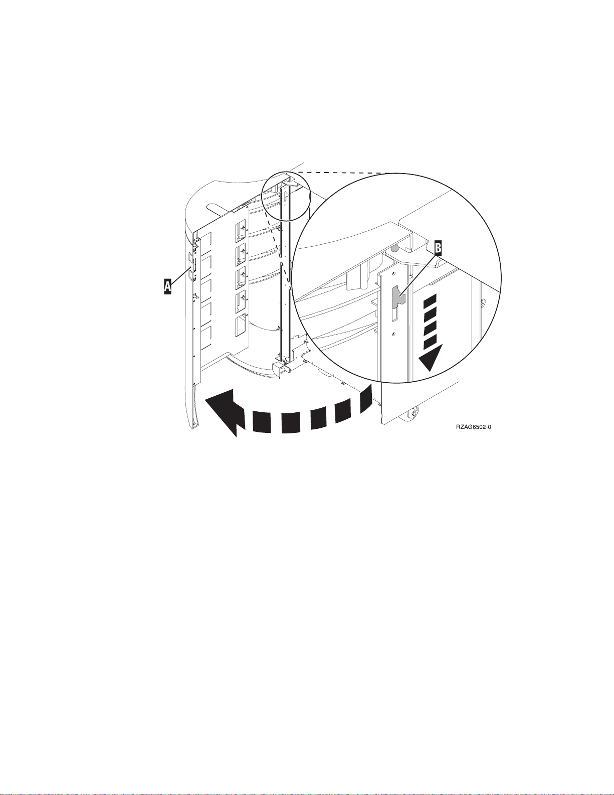
__ 5. Use the latch that is shown at A to open the back cover on your
expansion unit.
__ 6. If needed, use latch shown at B to remove the back cover.
© Copyright IBM Corp. 1999, 2000 7
Page 20
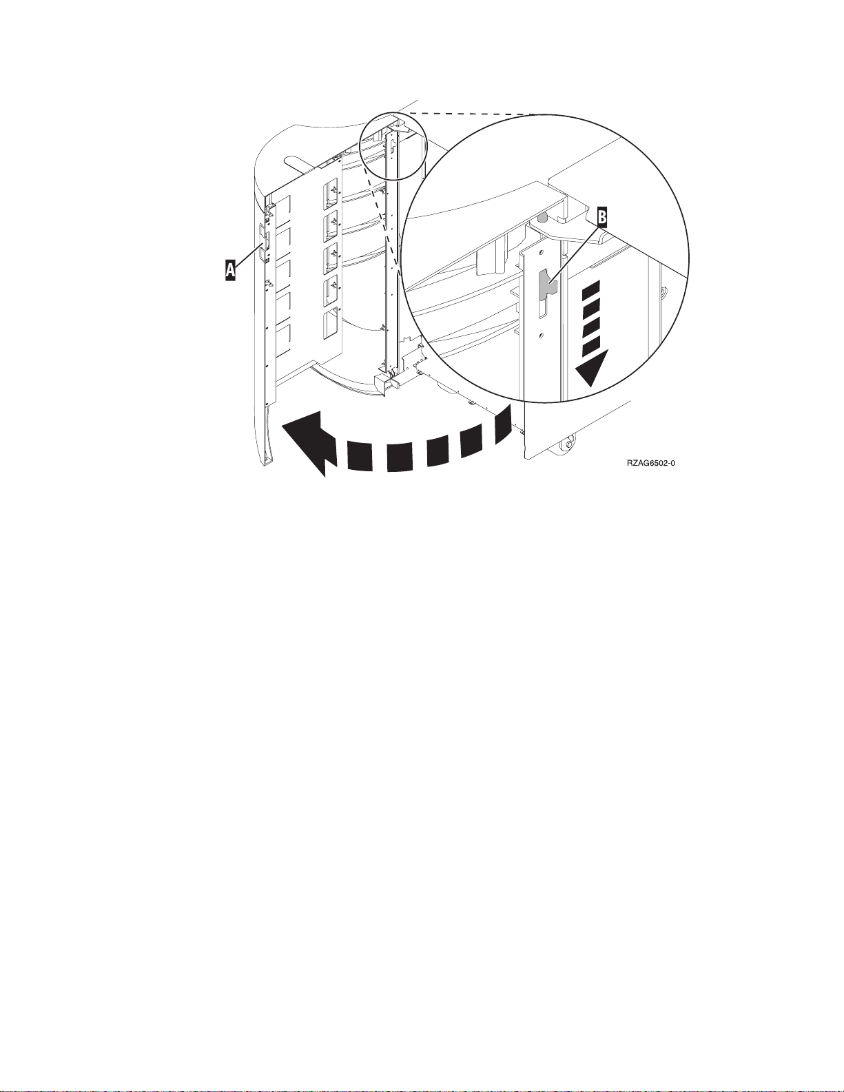
Figure 7. Opening or removing 5065 Expansion Unit back cover
__ 7. Refer to Figure 8 on page 9 and install the SPCN cable (PN 21F9469) by
performing the following steps:
__ a. Plug one end of the SPCN cable into the SPCN connector J15 on the
expansion unit.
__ b. Tighten the thumbscrews.
8 Setting Up Your 5065 or 5066 Expansion Unit V4R5
Page 21
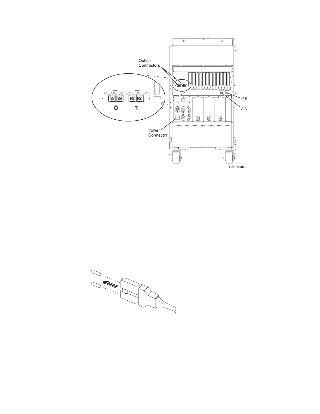
Figure 8. 5065 connector locations
__ 8. Install the optical cables by performing the following steps:
__ a. Locate the optical connector that is labeled 0 on the back of the
expansion unit.
__ b. Remove the terminating plugs from the optical connector.
Attention: When installing the cable connectors, use extreme care to
prevent damaging the housing or scratching the ends of the fiber optic
cables.
__ c. Remove the optical plug dust covers from the optical cable you are
installing.
__ d. Install the optical cable that is labeled 0 into the connector.
Figure 9. Removing optical plug dust covers
__ e. Repeat steps 8a through 8d to install the optical cable that is labeled 1
into the optical cable connector that is labeled 1.
__ 9. Find the power cord that you unpacked with the expansion unit.
__ 10. Locate the power connector on the back of the expansion unit.
__ 11. Remove the label that covers the power plug connector.
Chapter 2. Setting up your 5065 Expansion Unit 9
Page 22

CAUTION:
Do not plug the expansion unit into the electrical outlet at this time.
__ 12. Plug the power cord into the expansion unit.
__ 13. Close or install the back cover on the expansion unit.
Connecting the cables to your AS/400 system unit
You need to remove the back cover from your AS/400 system unit before you
connect the optical cable and the SPCN cable to it.
If your system unit is an AS/400e system 620 or S20, you may also need to remove
the side access cover. Go to “Appendix A. Connecting cables to your AS400e
System 620 or S20” on page 27 to determine if you need to remove the side cover.
If your system unit is not an AS/400e system 620, perform the following steps.
To connect the SPCN cable and the optical cable to the system unit, do the
following:
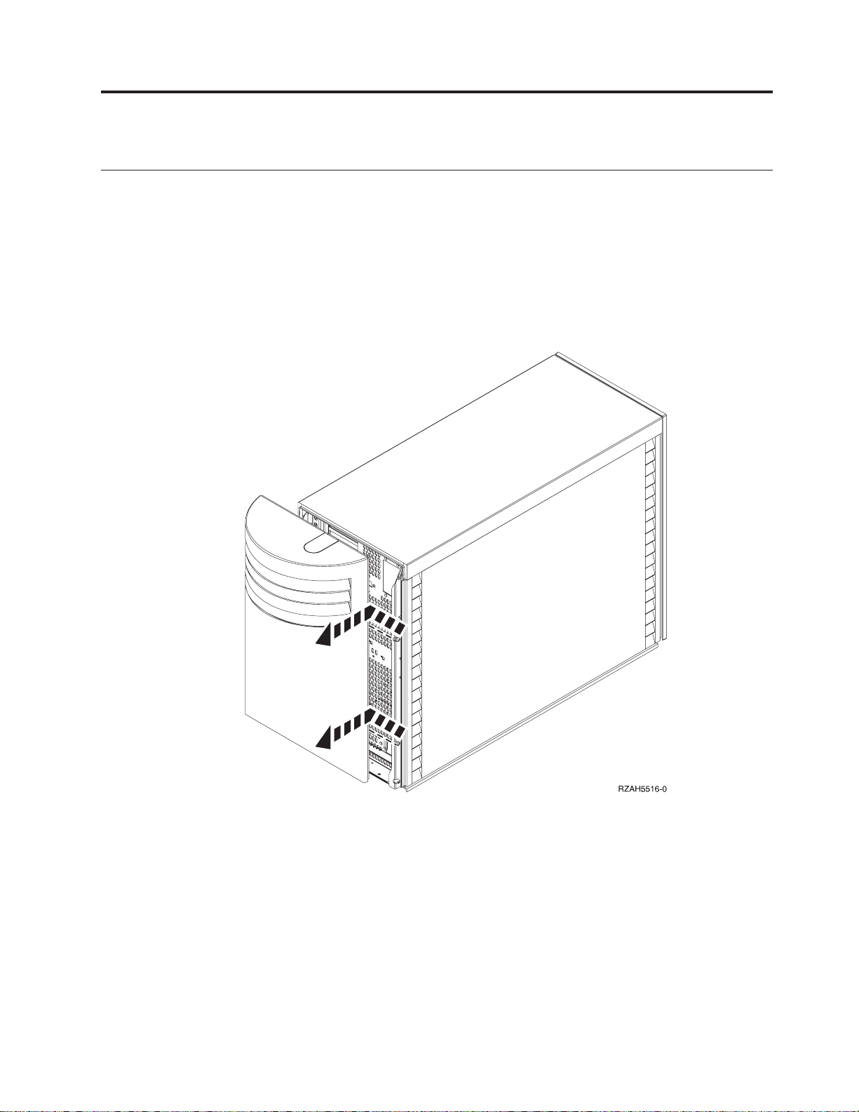
__ 1. Refer to Figure 10 and remove the system unit back cover by gripping the
upper corners of the cover and pulling it up and toward you.
Figure 10. Remove the system unit back cover
__ 2. Plug the SPCN cable that comes from your expansion unit into the
connector at the rear that is labeled SPCN.
__ 3. Tighten the thumbscrews.
To connect the optical cables to the system unit, follow these steps:
10 Setting Up Your 5065 or 5066 Expansion Unit V4R5
Page 23

__ 1. If you are installing your optical cables into an AS/400e system 620 or
AS/400e server 720 go to step 7. If you are installing your optical cables into
any other server, go to step 2.
__ 2. Locate the 2688 OLP card (Figure 11) on the back of your system unit.
Figure 11. 2688 OLP card
__ 3. Remove the terminating plugs from the optical card connectors.
__ 4. Push the optical cable that is labeled 0 into the top optical cable connector in
the system unit.
__ 5. Install the optical cable that is labeled 1(for the redundant link) from the
expansion unit into the bottom optical cable card connector.
__ 6. Go to 7f.
__ 7. If you are installing optical cables into an AS/400e system 620 or AS/400e
server 720 proceed as follows:
a. On the back of your system unit, locate the optical cable connectors that
have the following labels:
BUS 06 BUS 05
BUS 04 BUS 03
b. Choose the next available set of optical cable connectors.
c. Remove the terminating plugs from the optical cable connectors.
d. Install the optical cable that is labeled 1 into the even numbered optical
cable connector (BUS 06 or BUS 04).
e. Install the optical cable that is labeled 0 into the odd numbered optical
cable connector (BUS 05 or BUS 03)
Example: If the optical cable connectors that are available are BUS 06 and
BUS 05:
1) Install the optical cable that is labeled 1 into BUS 06.
2) Install the optical cable that is labeled 0 into BUS 05.
f. Install the system unit back cover (Figure 12 on page 12) by doing the
following:
__ 1) Grip the upper corners of the cover.
__ 2) Align the pins with the slots.
__ 3) Push the cover in and down.
__ 4) Go to “Chapter 5. Verifying Your New Configuration” on page 25.
Chapter 2. Setting up your 5065 Expansion Unit 11
Page 24

Figure 12. Install Back Cover
Connecting your 5065 Expansion Unit in a loop
Use this procedure to connect your 5065 to an expansion unit which is already
connected to your system unit. Your system unit should be powered down before
you proceed. If your system unit is not powered down, read “Powering down
your AS/400 system unit” on page 5 and power down your system unit.
To make this procedure simpler, refer to the other expansion unit as unit X, as is
shown in Figure 13.
Figure 13. Connecting your 5065 to another expansion unit
12 Setting Up Your 5065 or 5066 Expansion Unit V4R5
Page 25

__ 1. Find the sheet of labels for the optical cables in the information shipped
with your expansion unit. Make your own, if labels are not in the
information that is shipped with your expansion unit.
__ 2. Find the optical and the SPCN cables in the information that is shipped
with your expansion unit.
__ 3. Attach a label to each end of the optical cable.
__ 4. Label the optical cable 1.
Figure 14. Labeling the optical cables
__ 5. Remove the back cover from unit X by gripping the upper corners of the
cover and pulling it up and toward you.
__ 6. Refer to Figure 15 and locate the 2682 connector on the back of unit X.
Figure 15. 2682 OLP card
__ 7. Remove the top optical cable (the optical cable between your system unit
and unit X) from the 2682 connector. Do not disconnect the cable from the
system unit.
Chapter 2. Setting up your 5065 Expansion Unit 13
Page 26
__ 8. Remove the SPCN cable (the SPCN cable between system unit and unit X)
from connector J15 on unit X. Do not disconnect the cable from your
system unit.
__ 9. Use the latch that is shown at A to open the back cover on your
expansion unit.
__ 10. If needed, use latch that is shown at B to remove the back cover.
Figure 16. Opening or removing 5065 Expansion Unit back cover
__ 11. Refer to Figure 17 on page 15 and install the optical cable that you removed
from unit X into the optical connector on your 5065 that is labeled 0. The
optical cable should now run between your system unit and your 5065.
__ 12. Plug the SPCN cable that you removed from unit X into the SPCN
connector J15 on your 5065. The cable should now run between your
system unit and your 5065.
__ 13. Tighten the thumbscrews.
14 Setting Up Your 5065 or 5066 Expansion Unit V4R5
Page 27
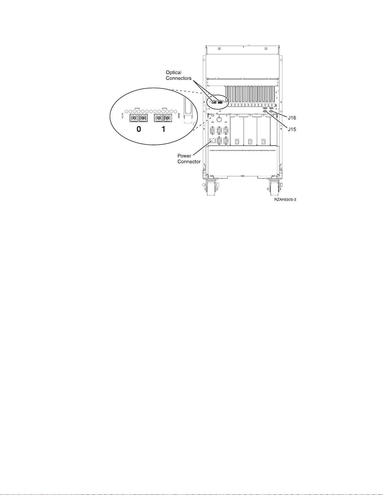
Figure 17. 5065 connector locations
__ 14. Remove the terminating plugs from the connector on the optical cable that
you labeled 1.
__ 15. Install one end of the optical cable that you labeled 1 into the optical
connector that is labeled 1 on your 5065.
__ 16. Install the other end of the cable that you labeled 1 into the lower optical
connection of the 2682 connector on unit X (Figure 15 on page 13).
__ 17. Connect one end of the SPCN cable that came with your 5065 into
connector J16 on your 5065.
__ 18. Connect the other end of the SPCN cable into connector J15 on unit X.
__ 19. Connect the power cable to your 5065.
__ 20. Install the back covers to unit X and your 5065.
__ 21. Go to “Chapter 4. Completing your installation” on page 23.
Chapter 2. Setting up your 5065 Expansion Unit 15
Page 28

16 Setting Up Your 5065 or 5066 Expansion Unit V4R5
Page 29
Chapter 3. Setting up your 5066 Expansion Unit
Opening the covers
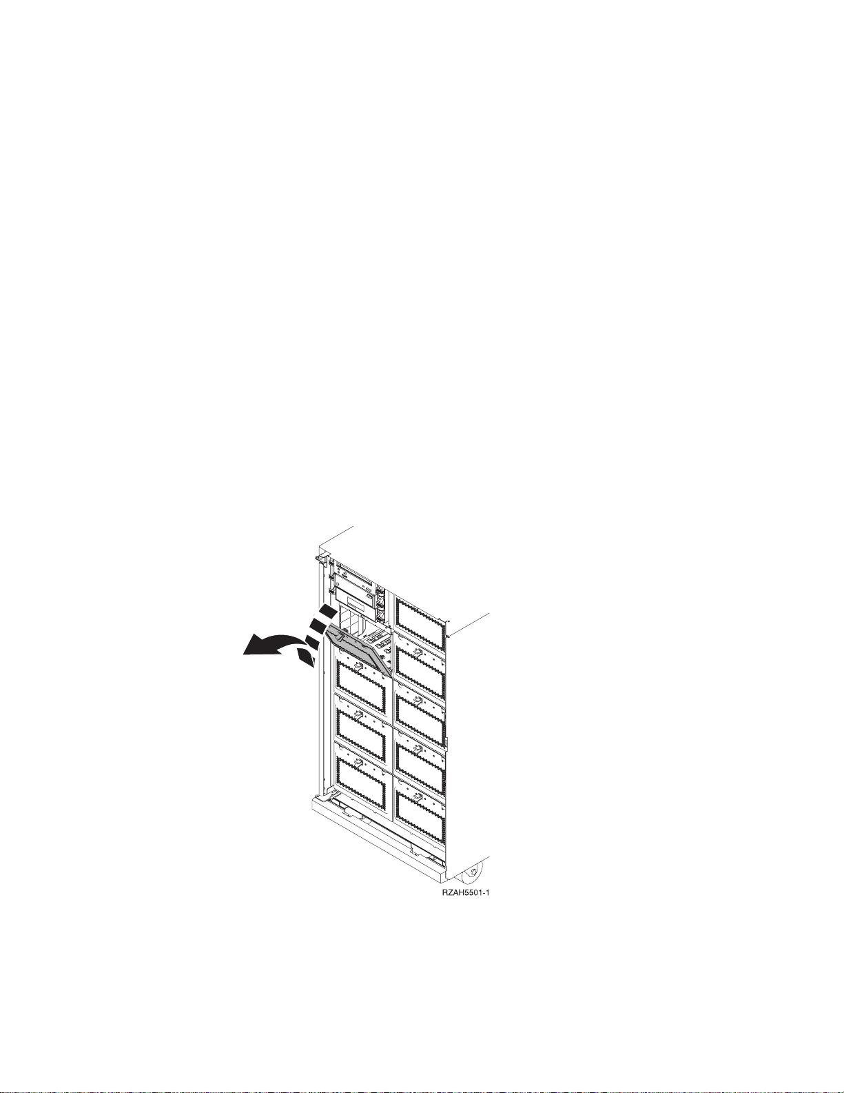
Before you can set up your 5066, you must remove the rear cover from your
AS/400 system unit and open the back cover on your 5066. Do these steps to open
and remove the covers:
1. Remove the rear cover from your system unit by lifting it up and toward you.
2. Open the rear cover on your 5066 by pressing the latch at A (Figure 19 on
page 18).
Figure 18. Removing the system unit cover
© Copyright IBM Corp. 1999, 2000 17
Page 30
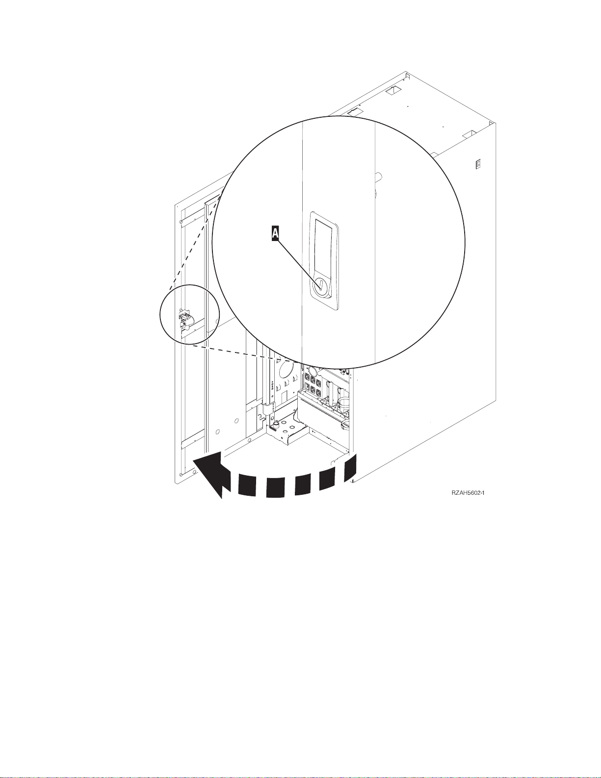
Figure 19. Opening the 5066 rear cover
18 Setting Up Your 5065 or 5066 Expansion Unit V4R5
Page 31
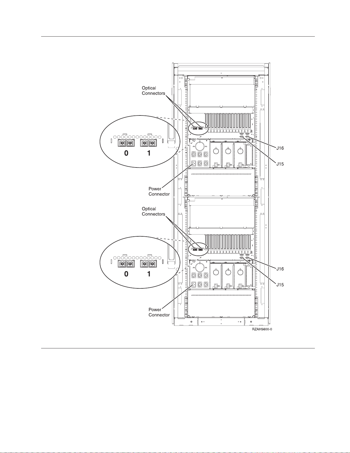
Locating 5066 connectors
Figure 20. 5066 connector locations
Connecting your 5066 to your system unit
Use the procedure below to connect your 5066 to your system unit.
Your 5066 consists of two independent 5065 Expansion Units in a single frame.
This procedure refers to the upper 5065 as 5066–002 and the lower 5065 as
5066–001. Refer to Figure 21 on page 20 and Figure 22 on page 20 before you start.
Chapter 3. Setting up your 5066 Expansion Unit 19
Page 32
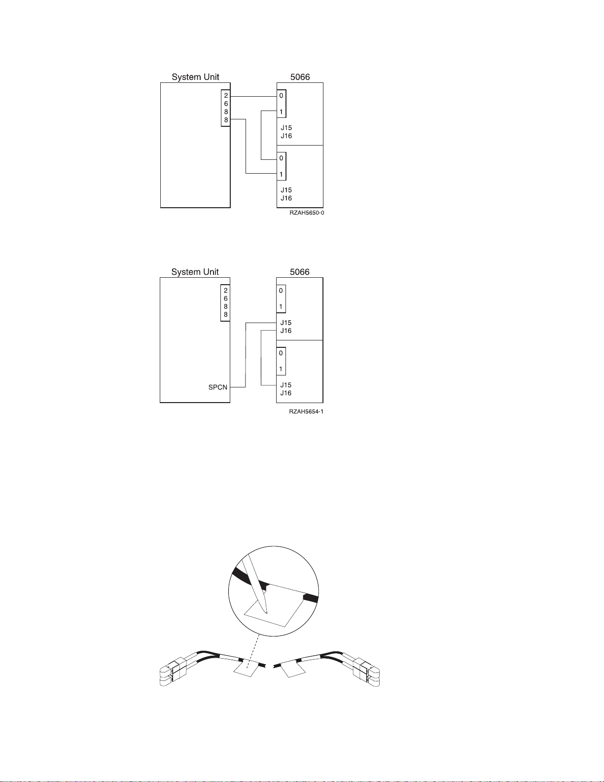
Figure 21. Connecting the optical cables.
Figure 22. Connecting SPCN cables
1. Find the optical cables and the SPCN cable in the information that is shipped
with your expansion unit. You will use three optical cables and two SPCN
cables to perform this procedure.
2. Locate an available 2688 OLP card (Figure 25 on page 21) on your system unit.
3. Remove the terminating plugs from the optical connectors on the OLP card.
4. Label each end of the optical cables (Figure 23).
Figure 23. Labeling the optical cables
20 Setting Up Your 5065 or 5066 Expansion Unit V4R5
Page 33
Attention: When installing the cable connectors, use extreme care to prevent
RV2D880-0
damaging the housing or scratching the ends of the fiber optic cables.
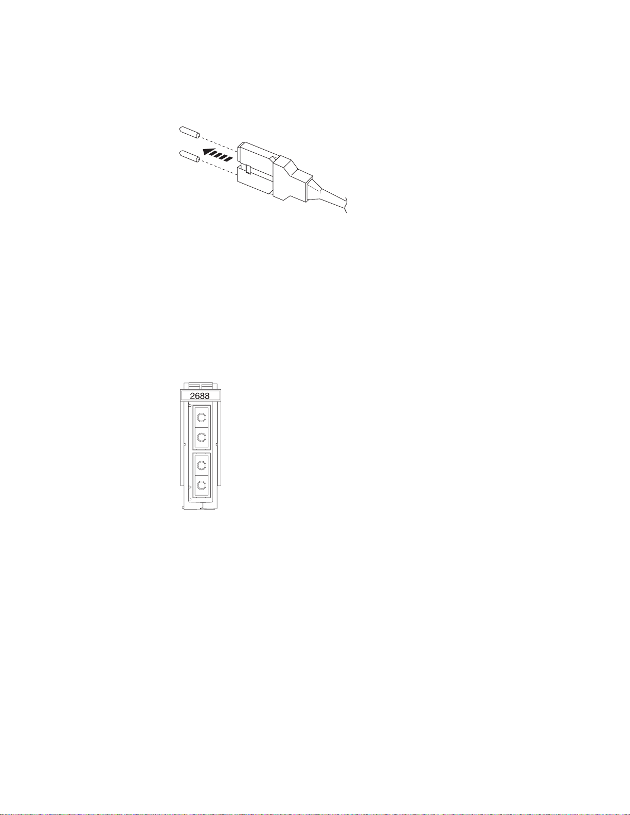
5. Remove the dust covers from the first optical cable.
Figure 24. Removing optical plug dust covers
Note: If your system unit is an AS/400e system 620 or server 720 the optical cables
connect to an optical cable connector with this label:
BUS 06 BUS 05
BUS 04 BUS 03
Use the next available set of connectors.
6. Install one end of the optical cable into the upper optical connector of the 2688
OLP card on your system unit (BUS 06 or BUS O4 for 620s and 720s).
Figure 25. 2688 OLP card
7. On unit 5066–002 locate the optical connectors that are labeled 0 and 1.
8. Remove the terminating plug from the optical connectors that are labeled 0
and 1.
9. On unit 5066–002, install the other end of the optical cable into the optical
connector that is labeled 0.
10. Remove the dust covers from the second optical cable.
11. On the unit 5066–002, install one end the second optical cable into the optical
connector that is labeled 1.
12. On unit 5066-001, install the other end of the optical cable into the optical
connector that is labeled 0.
13. Remove the dust covers from the third optical cable.
14. On unit 5066-001, install one end of the optical cable into the optical connector
that is labeled 1
15. Install the other end of the optical cable into the lower optical connector of the
2688 OLP card on your system unit (BUS 05 or BUS O3 for 620s and 720s).
Chapter 3. Setting up your 5066 Expansion Unit 21
Page 34

16. On your system unit, install one end of an SPCN cable into an available SPCN
connector. The SPCN connector is labeled J15 or J16.
17. Tighten the thumbscrews.
18. On unit 5066–002, connect the other end of the SPCN cable to the SPCN
connector that is labeled J15.
19. Tighten the thumbscrews.
20. On unit 5066-002, connect another SPCN cable to the SPCN connector that is
labeled J16.
21. Tighten the thumbscrews.
22. On unit 5066-001, connect the other end of the second SPCN cable to the
SPCN connector that is labeled J15.
23. Tighten the thumbscrews.
24. On your 5066 connect a power cable to each power connector.
25. Go to “Chapter 4. Completing your installation” on page 23.
22 Setting Up Your 5065 or 5066 Expansion Unit V4R5
Page 35
Chapter 4. Completing your installation
Perform the following steps to return complete your installation:
1. Make sure that you have reinstalled all of the covers on the following system
components:
a. AS/400 system unit.
b. All system expansion units.
DANGER
An electrical outlet that is not correctly wired could place hazardous voltage
on metal parts of the system or the products that attach to the system. It is the
customer’s responsibility to ensure that the outlet is correctly wired and
grounded to prevent an electrical shock. (RSFTD201)
2. Plug the power cords for the following system components into electrical
outlets:
__ a. The AS/400 system unit.
Note: If you are setting up a 5066 and the power cords are two different
lengths, install the longer power cord into the upper unit.
__ b. All expansion units attached to the system.
__ c. The system unit console.
__ d. The system printer.
3. Turn power on to each of the following system components by using the
associated power-on button:
a. The system printer (if present).
b. The system control console.
c. Ensure that the system is in normal mode, Figure 26.
Figure 26. Normal Mode
d. Turn on the AS/400 system unit by pushing the white power-on button.
Note: The time needed to do a complete IPL varies depending on AS/400
model and configuration.
e. Sign on the system unit. Ensure that you have service tools authority.
© Copyright IBM Corp. 1999, 2000 23
Page 36

24 Setting Up Your 5065 or 5066 Expansion Unit V4R5
Page 37

Chapter 5. Verifying Your New Configuration
Verify your new configuration by performing the following:
__ 1. On an AS/400 command line, type:
STRSST
Press the Enter key.
__ 2. When the Start a Service Tools menu appears, select the Start a service tool
option.
Press the Enter key.
__ 3. When the Start a Service Tool menu appears, select option 7 (Hardware
service manager).
Press the Enter key.
__ 4. When the Hardware Service Manager menu appears, select the Packaging
hardware resources (system, frames, cards...) option.
Press the Enter key.
Your new expansion unit appears on the list. If it does not, you need to
verify your installation by performing these steps:
a. Make sure that you powered on the expansion unit.
b. Make sure that you connected the optical cables correctly.
c. Make sure that you connected the SPCN cables correctly.
__ 5. For future reference, print the configuration list and place it in this book. To
print the configuration list proceed as follows:
a. You need to sign on with service authority.
b. On the AS/400 Main menu command line type:
STRSST
Press the Enter key.
c. On the STRSST display, select option 1 (Start a service tool).
Press the Enter key.
d. On the Start a Service Tool display, select option 7 (Hardware service
manager).
Press the Enter key.
e. From the Hardware Service Manager display, press F6 (print the
configuration).
Updating Vital Product Data
You need to update the Vital Product Data (VPD) for your system now that your
installation is complete. You should still be at the Hardware Service Manager
display. If you are not, follow steps 5b through 5d above. Do the steps below:
__ 1. At the Hardware Service Manager display, select option 5 (System power
control network (SPCN)).
__ 2. Press the Enter key.
__ 3. Locate your expansion unit on the System Configuration List that you
printed in step 5e.
© Copyright IBM Corp. 1999, 2000 25
Page 38

Notes:
a. If you installed a 5066, you need to find the Frame ID and Serial Number for
both 5066–002 and 5066–001.
b. You can also find the Frame ID by looking at the display on the expansion unit.
For example, if the Frame ID for your 5066–002 (the upper unit) is 4, a *04 will
appear on the display.
__ 4. On the System Configuration List, find the Frame ID and Serial Number for
your expansion unit.
__ 5. At the System Power Control Network display, select option 3 (Write VPD)
for your expansion unit. Press Enter.
Example: If the Frame ID for your expansion unit is 2, enter option 3, as is shown
in the example below. Use the Frame ID witha0intheUnit field.
System Power Control Network
Battery capacity test.......:Enabled
Type options, press Enter.
3=Write VPD 5=Display detail 6=Display trace log
7=Test battery interface
Opt Frame Unit Type Number Fault
01 0 00-00000 No
01 1 00-00000 No
03 0 .... 00-00000 No
03 1 .... 00-00000 No
3 02 0 .... 00-00000 No
02 1 .... 00-00000 No
Serial
__ 6. At the Write Vital Product Data (VPD) display enter the following
information:
a. At the Type field enter 5065 or 5066.
b. At the Model field, enter 001. If you have a 5066 enter 001 for 5066–001
(the lower unit) or 002 for the 5066–002 (the upper unit).
c. Enter the Serial Number at the Serial Number field.
__ 7. Press the Enter Key
__ 8. To return to the AS/400 Main menu, press F3 (Exit) three times and press
the Enter key.
Keep this book for future use. If you need to install disk units or removable media
devices, see “Appendix C. Installing disk units in the 5065 or 5066 Expansion Unit”
on page 37 or “Appendix D. Installing removable media devices in the 5065
Expansion Unit” on page 55.
Congratulations, you have completed your expansion unit installation.
26 Setting Up Your 5065 or 5066 Expansion Unit V4R5
Page 39

Appendix A. Connecting cables to your AS400e System 620
or S20
To connect cables to your 620, you may need to remove the side cover. To
determine if you need to remove the side cover do the steps in “Removing the
access cover for the AS/400e system 620 or server S20”.
Removing the access cover for the AS/400e system 620 or server S20
__ 1. Refer to Figure 10 on page 10 and remove the back cover for the system unit.
Grip the upper corners of the cover and pull it up and toward you.
__ 2. Look at the back of your system unit. Can you see the optical cable
connections on the back of your system unit?
No Yes
↓ You do not need to remove the side cover. Go to “Connecting the
cables to your AS/400 system unit” on page 10 and start the
procedure at step 2 on page 10.
__ 3. Remove the system unit front cover (Figure 27 on page 28) by doing the
following:
a. Unlock the front cover that is shown at A, if locked.
b. Slide up both latches (louvers) on the side covers as is shown at B to
unlatch the front cover.
c. Grip the upper corner of the front cover.
d. Lift the cover up and out.
© Copyright IBM Corp. 1999, 2000 27
Page 40

Figure 27. Removing the system unit front cover
__ 4. Remove the system unit top cover (Figure 28 on page 29) by doing the
following:
a. Find the top cover lock, shown at A, on the back of the system unit.
b. Loosen the screw and pivot the top cover lock at A out of the way.
c. Slide the cover (Figure 29 on page 29) forward toward the front of the
system unit.
d. Lift the cover up and remove.
28 Setting Up Your 5065 or 5066 Expansion Unit V4R5
Page 41
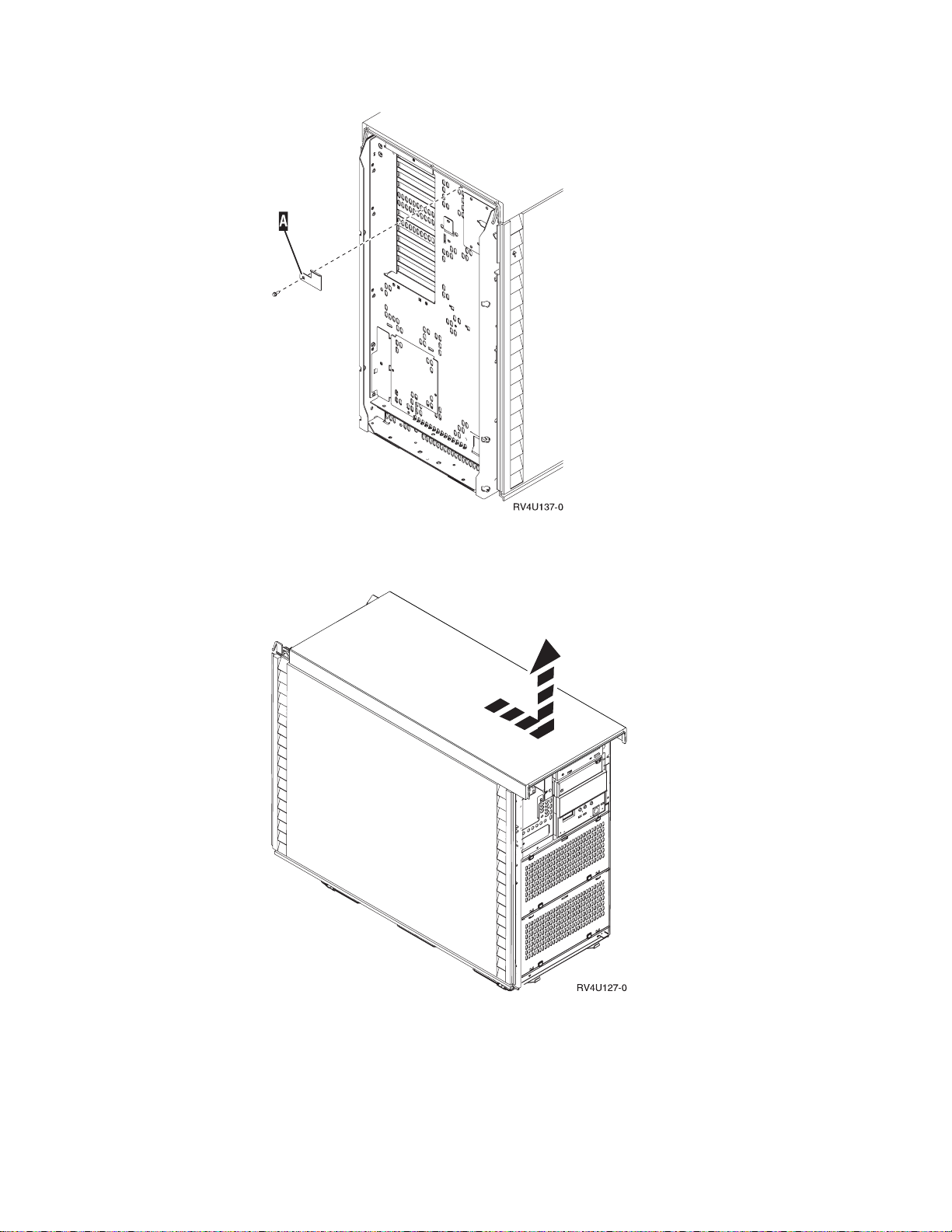
Figure 28. Removing the top cover lock
Figure 29. Removing the top cover
__ 5. Remove the system unit side cover (Figure 30 on page 30) as follows:
a. Slide up the cover latches that are shown at A to open the louvers and
expose the screws on either side of the cover.
b. When you remove the screws, do not lay them top of the system unit.
Appendix A. Connecting cables to your AS400e System 620 or S20 29
Page 42

c. Remove the two screws (B). The cover may fall if you do not hold on
to it.
d. Lift the cover out and up.
Figure 30. Removing the system unit side cover
__ 6. CAUTION:
The battery is a lithium battery. Only trained service personnel may
replace this battery using the instructions in the Problem Analysis, Repair,
and Parts service manual. To avoid possible explosion, do not burn or
charge the battery. Exchange only with the IBM-approved part. Discard
the battery as instructed by local regulations. (RSFTC241)
Your system unit contains a battery.
Remove the access cover (Figure 31 on page 31) by doing the following:
a. Remove all slotted-head screws that are labeled A and B on the access
cover. As you remove the screws:
v Keep them in a group (for example, in a small container).
v Make sure that you note from where you removed the screws.
This will make reinstalling the screws easier.
b. Grip the cover, pull toward you, and lift it out.
30 Setting Up Your 5065 or 5066 Expansion Unit V4R5
Page 43
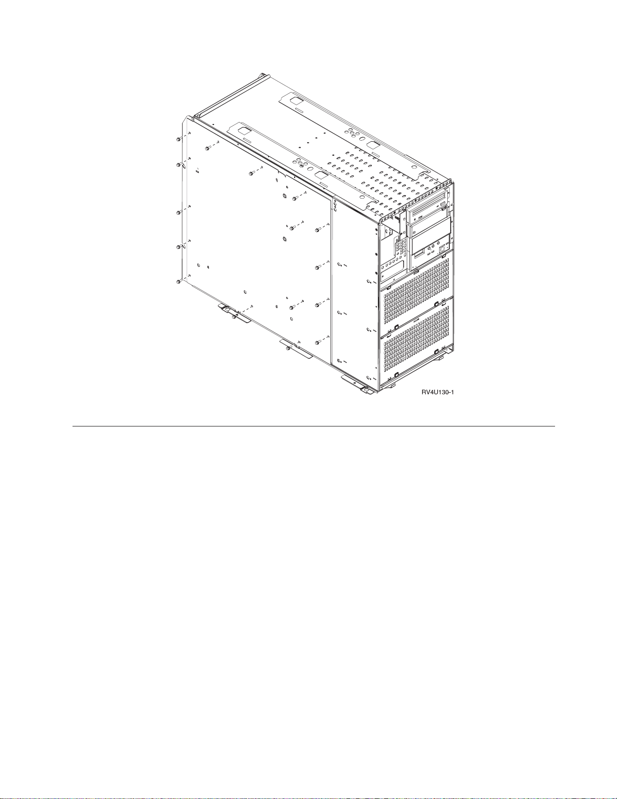
Figure 31. Removing system unit access cover
Connecting the SPCN and optical cables to the AS/400e system 620 or
server S20
To connect the SPCN cable and the optical cable to your system unit, follow these
steps:
__ 1. Plug the SPCN cable into the SPCN connector on your system unit.
__ 2. Tighten the thumbscrews.
Refer to Figure 32 on page 32 and install your optical cables:
__ 1. Locate the optical card connector inside of your system unit.
__ 2. On the back of the system unit, loosen two screws and open the cover plate.
__ 3. Route the optical cable to the optical connector through the back of your
system unit.
__ 4. Remove the two protective plugs from the 2688 OLP card.
__ 5. Push the optical cable that is labeled 0 into the OLP cable connector on the
left.
__ 6. Push the optical cable that is labeled 1 into the OLP cable connector on the
right.
__ 7. Go to “Replacing the covers on your AS/400e system 620 or server S20” on
page 32
Appendix A. Connecting cables to your AS400e System 620 or S20 31
Page 44

Figure 32. Installing optical cables in a system 620 or server S20
Replacing the covers on your AS/400e system 620 or server S20
__ 1. Install the access cover and secure with slotted-head screws.
__ 2. Install the side cover for the system unit as follows:
a. Install the side cover. The cover may fall if you do not hold on to it.
b. Secure with the two screws.
c. Slide the cover latches down to close the louvers.
__ 3. Install the top cover by sliding it towards the back of the system.
__ 4. Secure the screw and pivot the top cover lock.
__ 5. While gripping its upper corners, install the back cover.
__ 6. Install the AS/400 front cover by doing the following:
a. Install the cover
32 Setting Up Your 5065 or 5066 Expansion Unit V4R5
Page 45

b. Slide the latches (louvers) on the side covers down to latch the front
cover.
c. Lock the front cover.
__ 7. Install the system unit back cover by doing the following:
__ a. Grip the upper corners of the cover.
__ b. Align the pins with the slots.
__ c. Push the cover in and down.
Appendix A. Connecting cables to your AS400e System 620 or S20 33
Page 46

34 Setting Up Your 5065 or 5066 Expansion Unit V4R5
Page 47

Appendix B. Possible configurations with other expansion
units
Your 5065 or 5066 expansion unit is compatible with these expansion units:
v 5044 Expansion Unit
v 5072 Expansion Unit
v 5073 Expansion Unit
v 5082 Storage Expansion Unit
v 5083 Storage Expansion Unit
The number and combination of expansion units you can have depend on the type
of other expansion units and server you have. It also depends on whether or not
you have a 5044 Expansion Rack. If your expansion unit is a 5066, count it as two
5065s.
AS/400e server S20
The AS/400e server S20 will support any combination of the expansion units that
are listed below. You can have a total of four expansion units:
v 5065
v 5072
v 5073
v 5082
AS/400e system 620 and server 720
Table 2. Possible configuration for servers 620 and 720
Number of 5044s allowed Number of 5065, 5072, 5073, 5082, or 5083s allowed
20
12
04
AS/400e servers S30 and S40
AS/400e servers S30 and S40 support any combination of the expansion units that
are listed below. You can have a total of 18 expansion units:
v 5065
v 5072
v 5073
v 5082
AS400e servers 640, 650, 730, and 740
Table 3. Possible configuration for servers 640, 650, 730, and 740
Number of 5044s allowed Number of 5065, 5072, 5073, 5082, or 5083s allowed
90
© Copyright IBM Corp. 1999, 2000 35
Page 48

Table 3. Possible configuration for servers 640, 650, 730, and 740 (continued)
Number of 5044s allowed Number of 5065, 5072, 5073, 5082, or 5083s allowed
82
74
66
58
410
312
214
116
018
36 Setting Up Your 5065 or 5066 Expansion Unit V4R5
Page 49

Appendix C. Installing disk units in the 5065 or 5066
Expansion Unit
You may install new disk units into the 5065 or 5066 Expansion Unit or yourself. It
takes approximately 1 hour to install the hardware.
You may also elect not to install the feature. Contact IBM or an authorized dealer
to make arrangements for them to install the disk unit feature for a fee.
Allow additional time to complete your jobs, back up your system, IPL your
system, and verify your hardware configuration.
When you use these instructions, you will do the following:
v Remove the front cover for the expansion-unit.
v Install one or more new disk units.
v Install the cover.
v IPL your operating system.
v Verify your new hardware configuration.
Note: Your 5066 Expansion Unit consists of two independent 5065 Expansion
Units. The installation instructions for each expansion unit in your 5066 are
identical.
Before you begin:
v Ensure that you have a current backup of your operating system and licensed
programs. If you have backed up the operating system and licensed programs
since the last time you applied PTFs, that backup is acceptable.
v Ensure that you take a few minutes to become familiar with these instructions.
v If there are incorrect, missing, or visibly damaged parts, contact one of the
following:
– Your authorized dealer
– IBM Rochester Manufacturing Automated Information Line (R-MAIL)
- 1-800-300-8751 (United States)
- 1-507-253-5242 (worldwide)
Optimizing your new disk unit
When you install a disk unit, you should optimize it for maximum performance by
evenly distributing the disk units on the disk controllers.
Note: If you are installing feature 4331 1.65 GB Read Cache, solid-state disk units,
you can only install them in position one of your disk unit enclosures. You
can install three of these features (if you have three disk unit controllers) in
the expansion unit.
Refer to the label on the inside of the front cover and install the disk units in this
sequence:
1. First fill all the disk unit positions that are controlled by the first high speed
disk unit controller.
© Copyright IBM Corp. 1999, 2000 37
Page 50

a. Fill the slot 1’s: D31, D36, D46
b. Fill the slot 2’s D32, D37, D47
c. Fill the slot 3’s: D33, D38, D48
d. Fill the slot 4’s: D34, D39, D49
e. Fill the slot 5’s: D35, D40, D50
2. Your expansion unit requires a second high speed disk unit controller before
you can install disk units into the following positions. Contact IBM or an
Authorized Dealer if your expansion unit does not have a second high speed
disk unit controller (IOA Card 2).
Next fill the slots in (IOA Card 2) this sequence:
a. Fill the slot 1’s: D01, D11, D21
b. Fill the slot 2’s: D02, D12, D22
c. Fill the slot 3’s: D03, D13, D23
d. Fill the slot 4’s: D04, D14, D24
e. Fill the slot 5’s: D05, D15, D25
3. Your expansion unit requires a third high speed disk unit controller before you
can install disk units into the following positions. Contact IBM or an
Authorized Dealer if your expansion unit does not have a third high speed disk
unit controller (IOA Card 3).
Last fill the slots in (IOA Card 3) this sequence:
a. Fill the slot 1’s: D06, D16, D26
b. Fill the slot 2’s: D07, D17, D26
c. Fill the slot 3’s: D08, D18, D28
d. Fill the slot 4’s: D09, D19, D29
e. Fill the slot 5’s: D10, D20, D30
Installing a disk unit
Follow these steps to install a disk unit. If you encounter difficulties during the
installation, contact your authorized dealer or service provider.
__ 1. Is your main system-unit powered off?
__ 2. Refer to Figure 33 on page 39 (5065) or Figure 34 on page 40 (5066) and use
__ 3. If needed, use the latch that is shown at B to remove the front cover.
No Yes
↓ Go to step 4 on page 48.
the latch that is shown at A to open the front cover.
38 Setting Up Your 5065 or 5066 Expansion Unit V4R5
Page 51

Figure 33. Opening the front cover door (5065)
Appendix C. Installing disk units in the 5065 or 5066 Expansion Unit 39
Page 52

Figure 34. Opening the front cover door (5066)
__ 4. Attach the disposable wrist strap to prevent electrostatic discharge from
damaging a device.
Notes:
a. The 2209 Disposable Wrist Strap is for static control. It will not increase
nor decrease your risk of receiving electric shock when using or working
on electrical equipment. Follow the same precautions you would use
without the wrist strap.
b. If the disposable wrist strap appears damaged or cut, discard the wrist
strap immediately and contact your dealer for a replacement. Do not
continue until a new wrist strap is available.
40 Setting Up Your 5065 or 5066 Expansion Unit V4R5
Page 53

c. When you unroll the wrist strap, remove the liner from the copper foil at
the end.
d. Attach the copper foil to an exposed, unpainted metal surface on the
frame of the expansion unit (electrical ground).
__ 5. Read “Concurrent procedure (system-unit powered on)” to be sure you
understand the concurrent procedure before you begin. If you do not feel
comfortable using the concurrent procedure, go to “Nonconcurrent
procedure (system-unit powered off)” on page 47.
Concurrent procedure (system-unit powered on)
Before you perform a concurrent install, you must first determine the Direct Select
Address for the disk unit you are installing. Read “Finding the Direct Select
Address”. Once you know the Direct Select Address, go to “Performing the
concurrent install” on page 43 to complete the install.
Finding the Direct Select Address
Follow these steps to find the Direct Select Address for the position you will be
installing your new disk unit:
__ 1. Refer to the label on the inside of the front cover for the location of your
new disk unit (as directed in “Optimizing your new disk unit” on page 37).
__ 2. Look at Table 4 to find the Direct Select Address for the location of your
new disk unit.
Table 4. Disk unit Direct Select Address
Location Direct Select Address
D01 0X20 0003 00FF
D02 0X20 0004 00FF
D03 0X20 0005 00FF
D04 0X20 0006 00FF
D05 0X20 0007 00FF
D06 0X30 0003 00FF
D07 0X30 0004 00FF
D08 0X30 0005 00FF
D09 0X30 0006 00FF
D10 0X30 0007 00FF
D11 0X20 0103 00FF
D12 0X20 0104 00FF
D13 0X20 0105 00FF
D14 0X20 0106 00FF
D15 0X20 0107 00FF
D16 0X30 0103 00FF
D17 0X30 0104 00FF
D18 0X30 0105 00FF
D19 0X30 0106 00FF
D20 0X30 0107 00FF
D21 0X20 0203 00FF
D22 0X20 0204 00FF
Appendix C. Installing disk units in the 5065 or 5066 Expansion Unit 41
Page 54

Table 4. Disk unit Direct Select Address (continued)
Location Direct Select Address
D23 0X20 0205 00FF
D24 0X20 0206 00FF
D25 0X20 0207 00FF
D26 0X30 0203 00FF
D27 0X30 0204 00FF
D28 0X30 0205 00FF
D29 0X30 0206 00FF
D30 0X30 0207 00FF
D31 0X10 0001 00FF
D32 0X10 0002 00FF
D33 0X10 0003 00FF
D34 0X10 0004 00FF
D35 0X10 0005 00FF
D36 0X10 0103 00FF
D37 0X10 0104 00FF
D38 0X10 0105 00FF
D39 0X10 0106 00FF
D40 0X10 0107 00FF
D46 0X10 0203 00FF
D47 0X10 0204 00FF
D48 0X10 0205 00FF
D49 0X10 0206 00FF
D50 0X10 0207 00FF
__ 3. To determine the value for X (BUS) perform the following steps:
a. If you have not already done so, print the System Configuration List:
1) On an AS/400 command line, type:
STRSST
Press the Enter key.
2) When the Start a Service Tools menu appears, select the Start a
service tool option.
Press the Enter key.
3) When the Start a Service Tool menu appears, select the Hardware
service manager option.
Press the Enter key.
4) When the Hardware Service Manager menu appears, select the
Packaging hardware resources (system, frames, cards...) option.
Press the Enter key.
5) When Confirm Remove of Packaging Hardware Resources(s) appears,
press F6 to print the configuration list.
6) To return to the Main menu, press F3 three times and then press the
Enter key.
42 Setting Up Your 5065 or 5066 Expansion Unit V4R5
Page 55
b. On the System Configuration List, locate your expansion unit.
c. Once you locate your expansion unit, look at the Logical Address field.
The value for X is the second digit in the field.
__ 4. Place the configuration list in this book.
Example: The following is an example of how to find the Direct Select Address for
location D02. The Direct Select Address from for location D02 is 0X20
0004 00FF. The value for X is under the LOGICAL ADDRESS field in the
System Configuration List as is shown in the example below:
LOGICAL ADDRESS
1/4/ /-/////
Under the LOGICAL ADDRESS field, the second digit is 4. Therefore the
Direct Select Address for location D02 in this example is 0420 0004 00FF.
__ 5. Locate the next available slot for the disk unit by reviewing the steps in
“Optimizing your new disk unit” on page 37.
__ 6. Record the Direct Select Address for your disk unit to use in the concurrent
install procedure.
Performing the concurrent install
After you find the Direct Select Address, perform these steps to concurrently install
your disk unit:
__ 1. Refer to Figure 35 and remove the enclosure shield for the disk unit.
Figure 35. Removing the disk unit enclosure shield
__ 2. Remove the long plastic connector cover from the position you will be
installing the new disk unit.
__ 3. Attention: Failure to follow these instructions could result in damage to
the new disk unit or the system-unit and could result in loss of data.
Appendix C. Installing disk units in the 5065 or 5066 Expansion Unit 43
Page 56

Sign on as QSECOFR.
__ 4. On the AS/400 Main Menu command line, type:
STRSST
Press the Enter key.
__ 5. When the System Service Tool display appears, select the Start a service
tool option. Press the Enter key.
__ 6. When the Start a Service Tool display appears, select the Hardware service
manager option. Press the Enter key.
__ 7. When the Hardware Service Manager display appears, select the Device
Concurrent Maintenance option.
__ 8. Type the Direct Select Address of the position where you are installing the
new disk unit.
__ 9. Select option 2 (Install device for the action to be performed).
__ 10. Set the time delay for one minute.
01
__ 11. Attention: Disk units are fragile. Handle with care.
Be sure to use the wrist strap provided. Place one end of the wrist strap
around your wrist and connect the opposite end to your system-unit.
__ 12. Find the package that contains the new disk unit assembly and remove it
from the static-protective package. Write the serial number (SN xx-xxxxxxx)
of the disk unit here ______________ before you install it.
__ 13. Hold the disk unit with the blue handle up.
__ 14. Unlock the blue handle by pulling it out toward you as far as possible
before you install the disk unit into the expansion unit.
__ 15. Refer to Figure 36 on page 45 and support the bottom of the disk unit
assembly as you slide it half way into the next available position. Do not
push it any further.
Note: Watch the light above the disk unit. When the light comes on and begins to
blink rapidly, you have nine seconds to install the disk unit.
__ 16. On the console, press the Enter key.
__ 17. Refer to Figure 36 on page 45 and when the light starts blinking, slide the
disk unit in and lock it in place by closing the latch.
44 Setting Up Your 5065 or 5066 Expansion Unit V4R5
Page 57

Figure 36. Installing a disk unit
__ 18. The green light stops blinking and remains on solid when you installed
disk unit properly.
__ 19. Return to the console and wait until the Concurrent Maintenance Results
display appears.
Press the Enter key.
__ 20. Do you have more disk units to install?
No Yes
↓ Repeat steps 5 on page 44 through 19.
__ 21. When the Hardware Service Manager display appears, press F12.
__ 22. On the System Service Tool display, select Work with Disk Units.
Press the Enter key.
__ 23. On the Work with Disk Units display, select Display disk configuration.
Press the Enter key.
__ 24. On the Display disk configuration display, select Display non-configured
units.
Press the Enter key.
__ 25. The display should list the disk unit that you installed. The serial number
should match the serial number you wrote in step 12 on page 44.
Note: If the display does not list the disk unit, ensure that you properly
installed the disk unit. Repeat steps 1 on page 43 through 19.
__ 26. Press F12, twice.
__ 27. On the Work with disk units display, select Work with disk configuration.
Press the Enter key.
__ 28. Are you adding a disk unit to an existing device parity set? If you need
more information about device parity, go to the Backup and Recovery,
SC41-5304-04 .
Appendix C. Installing disk units in the 5065 or 5066 Expansion Unit 45
Page 58

Yes No
↓ Go to step 45.
__ 29. On the Work with disk configuration display, select Include unit in device
parity protection.
__ 30. Did the Include Device Parity Protection Failed display appear?
Yes No
↓ Go to step 33.
__ 31. You must meet the following conditions before you can start device parity
protection. Including the disk unit in device parity protection may fail for
one or more reasons.
v If there are enough disk units available to create a new parity set, the
units will be eligible for Start Device Parity Protection operation. The
units will not be eligible for the Include Device Parity Protection
operation. For more information, go to the Backup and Recovery,
SC41-5304-04 .
v All disk units in a parity set must be the same capacity. The resulting
parity set must have a minimum number of 4 disk units and
maximum of 10 units.
v Not all disk units attached to an advanced function input/output
processor have reported to the system. Retry the operation.
v The type/model of the disk units is not supported for the requested
operation.
__ 32. When the above conditions have been met, select F12 to return to the Work
with disk configuration display.
__ 33. On the Include Disk Units in Device Parity Protection display, select the
disk units to be included in Device Parity Protection by typing a 1 in the
Option column.
Press the Enter key.
__ 34. Press Enter to confirm your choice.
__ 35. When the device parity protection is complete, the message “Selected units
have been included successfully” appears on the Work with disk
configuration display.
__ 36. On the Work with disk configuration display, select Display disk
configuration.
__ 37. On the Display disk configuration display, select Display disk configuration
status.
__ 38. Determine the auxiliary storage pool (ASP) to add the disk unit to.
__ 39. Press F12, twice.
__ 40. On the Work with disk configuration display, select Add units to the ASPs
and balance data.
Press the Enter key.
__ 41. On the Specify to Add Units to display, specify the ASP.
Press the Enter key.
__ 42. Press Enter to confirm.
__ 43. When the message “Selected units have been added successfully”, return to
the AS/400 Main menu.
__ 44. Go to step 48 on page 47.
__ 45. On the Work with disk configuration display, select Add units to ASPs.
46 Setting Up Your 5065 or 5066 Expansion Unit V4R5
Page 59

Press the Enter key.
__ 46. Add the number of the ASP you want to add the disk unit to. The system
ASP is ASP 1.
Press the Enter key.
__ 47. The Confirm Add Units display appears showing the configuration your
system will have when the add completes.
Note: If you have selected the wrong ASP, press F12 to change your
options.
Press the Enter key to continue. The add process will take several minutes
to complete.
__ 48. Install the disk unit shield cover .
__ 49. Install the system unit front cover.
__ 50. If you have a printer, print the configuration list. A service representative
may refer to the configuration list in the future.
a. On the AS/400 Main menu command line type:
Note: You need to be signed on with service authority.
STRSST
Press the Enter key.
b. On the STRSST display, select Start a service tool option.
Press the Enter key.
c. On the Start a Service Tool display, select Hardware service manager
option.
Press the Enter key.
d. From the Hardware Service Manager display, press F6 (print the
configuration).
e. To return to the AS/400 Main menu, press F3 (Exit) twice and then
press the Enter key.
f. Place the configuration list in the Basic System Operation, Administration,
and Problem Handling, SC41-5206-04 book.
__ 51. For information on how to make your disk unit operational, go to the
AS/400 Information Center. You can access the Information Center from the
AS/400 Information Center, SK3T-2027-03 or from the following web site:
http//www.as400.ibm.com/infocenter
__ 52. Keep all miscellaneous parts, such as wrap connectors, with the Service
Materials box or in a safe place.
The installation of the disk unit is complete.
Nonconcurrent procedure (system-unit powered off)
__ 1. If you have installed logical partitions on your system-unit, refer to the
AS/400 Information Center. At the AS/400 Information Center, you can
find instructions on powering down a system with logical partitions.
__ 2. Ensure that all jobs are complete.
__ 3. When all jobs are complete, type the following on an AS/400 command
line:
pwrdwnsys *immed
Press the Enter key.
Appendix C. Installing disk units in the 5065 or 5066 Expansion Unit 47
Page 60

__ 4. When you have completely powered down the system-unit, power off all
PCs and devices, such as printers and displays, that are connected to the
system-unit.
__ 5. Unplug any power cords, such as printers and displays, from electrical
outlets.
__ 6. Unplug the system-unit power cord from the electrical outlet.
__ 7. Refer to Figure 33 on page 39 use the latch that is shown at A to open the
front cover.
__ 8. If needed, use the latch that is shown at B to remove the front cover.
__ 9. Attach the disposable wrist strap to prevent electrostatic discharge from
damaging a device.
Notes:
a. Follow the same precautions you would use without the wrist strap.
The 2209 Disposable Wrist Strap is for static control. It will not increase
nor decrease your risk of receiving electric shock when using or
working on electrical equipment.
b. If the disposable wrist strap appears damaged, discard the wrist strap
immediately and contact your dealer for a replacement. Do not
continue until a new wrist strap is available.
c. When you unroll the strap, remove the liner from the copper foil at the
end.
d. Attach the copper foil to an exposed, unpainted metal surface on the
frame of the expansion unit (electrical ground).
__ 10. Attention: Disk units are fragile. Handle with care.
Be sure to use the wrist strap provided. Place one end of the wrist strap
around your wrist and ensure that you connected the opposite end to the
expansion unit.
__ 11. Locate the next available position for the disk unit by reviewing the steps
in “Optimizing your new disk unit” on page 37.
__ 12. Find the package that contains the new disk unit assembly and remove it
from the static-protective package.
__ 13. Write the serial number (SN xx-xxxxxxx) of the disk unit here
______________ before you install it.
__ 14. Refer to Figure 37 on page 49 and remove the enclosure shield for the disk
unit.
48 Setting Up Your 5065 or 5066 Expansion Unit V4R5
Page 61

Figure 37. Removing the disk unit enclosure shield
__ 15. Remove the long plastic connector cover from the position you will be
installing the new disk unit.
__ 16. Attention: Failure to follow these instructions could result in damage to
the new disk unit or the expansion unit and could result in loss of data.
Sign on as QSECOFR.
__ 17. Unlock the blue handle by pulling it out toward you before you install the
disk unit into the expansion unit.
Note: Support the disk unit as you install it into the expansion unit. Do not hold
the disk unit by the blue handle.
__ 18. Refer to Figure 38 on page 50 and slide the disk unit into the expansion
unit until it stops.
__ 19. Lift the disk unit handle until it locks into place.
Appendix C. Installing disk units in the 5065 or 5066 Expansion Unit 49
Page 62
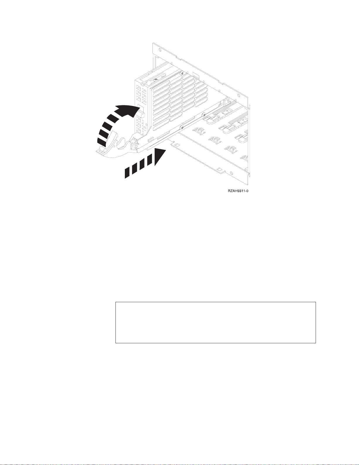
Figure 38. Installing a disk unit
__ 20. Do you have any additional disk units to install?
No Yes
↓ Repeat steps 12 on page 48 through 19 on page 49.
__ 21. Do you have any other devices to install?
No Yes
↓ If you have another device such as a tape unit or CD-ROM drive,
go to the instructions that came with that device.
__ 22. Install the enclosure shield cover for the disk unit.
__ 23. Install the front cover of the expansion unit.
__ 24. DANGER
An electrical outlet that is not correctly wired could place hazardous
voltage on metal parts of the system or the products that attach to the
system. It is the customer’s responsibility to ensure that the outlet is
correctly wired and grounded to prevent an electrical shock.
(RSFTD201)
Plug the following power cords into an electrical outlet.
v System-unit
v Console for the system
__ 25. Plug in and power on all attached devices, such as printers and displays.
50 Setting Up Your 5065 or 5066 Expansion Unit V4R5
Page 63
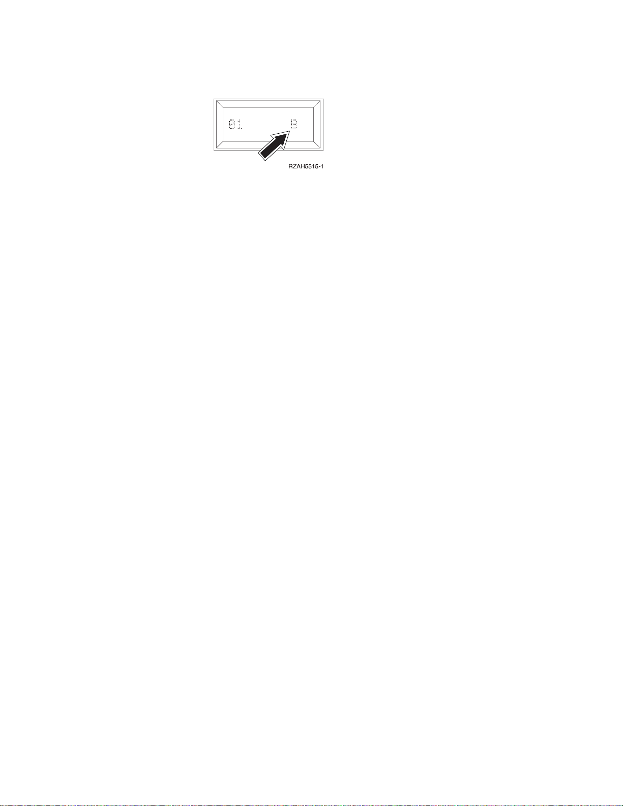
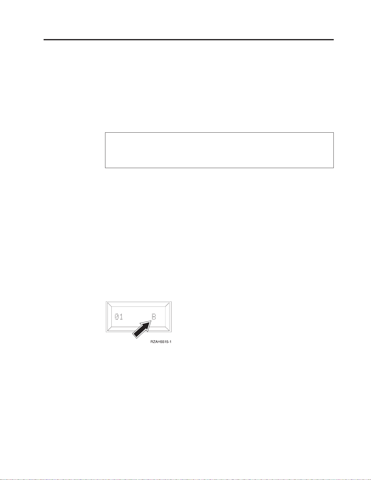
__ 26. Look at the Function/Data display on the control panel. Does a B appear
in the Function/Data display?
Yes No
↓ Do the following:
a. Press the Up or Down select push button until 02 appears in
the Function/Data display.
b. Press the Enter push button on the control panel.
c. Press the Up or Down select push button until B appears in the
Function/Data display.
d. Press the Enter push button on the control panel.
e. Press the Up or Down select push button until 01 appears in
the Function/Data display.
f. Press the Enter push button on the control panel.
__ 27. Make sure that the IPL mode is in Manual mode. If it is not press, the
Mode button until a light indicates that Manual is the active mode.
__ 28. Power on the workstation or PC that is your system-unit console
__ 29. Press the power button to power on the AS/400 server.
__ 30. Do the following to verify your disk unit configuration:
__ 31. Do the following to verify your disk unit configuration:
a. When the IPL or install the System menu appears, select the Use
dedicated service tools option.
Press the Enter key.
b. On the Dedicated Service Tools (DST) Sign-On display, enter your DST
Userid and password.
Note: The default DST password is 22222222222, unless it has been
changed.
Press the Enter key.
c. When the Use Dedicated Service Tools menu appears, select the Work
with disk units option.
Press the Enter key.
d. When the Work with Disk Units display appears, select the Work with
disk configuration option.
Press the Enter key.
e. When the Work with Disk Configuration menu appears, select the
Display disk configuration option.
Press the Enter key.
f. When the Display Disk Configuration menu appears, select the Display
non-configured units option.
Press the Enter key.
Appendix C. Installing disk units in the 5065 or 5066 Expansion Unit 51
Page 64

g. The disk unit that you installed should appear in the list. The serial
number should match the serial number you wrote in step 13 on page
48.
Note: If the disk unit does not appear in the list, ensure that you
properly installed the disk unit.
h. Return to the Work with Disk Units menu (Press F12 three times).
__ 32. On the Work with disk units display, select Work with disk configuration.
Press the Enter key.
__ 33. Are you adding a disk unit to an existing device parity set? If you need
more information about device parity, go to the book, Backup and Recovery,
SC41-5304-04 .
Yes No
↓ Go to step 52 on page 53.
__ 34. On the Work with Disk Configuration display, select Work with device parity
protection.
__ 35. On the Work with Device Parity Protection display, select Include unit in device
parity protection.
__ 36. Did the Include Device Parity Protection Failed display appear?
Yes No
↓ Go to step 39.
__ 37. You must meet the following conditions before you can start device parity
protection. Including the disk unit in device parity protection may fail for
one or more reasons.
v If there are enough disk units available to create a new parity set, the
units will be eligible for Start Device Parity Protection operation. The disk
units will not be eligible for the Include Device Parity Protection operation.
For more information, go to the Backup and Recovery, SC41-5304-04 .
v All disk units in a parity set must be the same capacity. The resulting
parity set must have a minimum number of 4 disk units and
maximum of 10 units.
v Not all disk units attached to an advanced function input/output
processor have reported to the system. Retry the operation.
v The type/model of the disk units is not supported for the requested
operation.
__ 38. When you have met the above conditions, select F12 to return to the Work
with disk configuration display.
__ 39. On the Include Disk Units in Device Parity Protection display, select the disk
units to be included in Device Parity Protection by typing a 1 in the Option
column.
Press the Enter key.
__ 40. Press Enter to confirm your choice.
__ 41. When the device parity protection is complete, the message “Selected
unit(s) have been included successfully” appears on the Work with device
parity protection display.
Press F12.
__ 42. On the Work with disk configuration display, select Display disk configuration.
Press the Enter key.
52 Setting Up Your 5065 or 5066 Expansion Unit V4R5
Page 65

__ 43. On the Display disk configuration display, select Display disk configuration
status.
__ 44. Determine the auxiliary storage pool (ASP) to add the disk unit to.
__ 45. Press F12, twice.
__ 46. On the Work with disk configuration display, select Work with ASP
configuration.
Press the Enter key.
__ 47. On the Work with disk configuration display, select Add units to ASPS and
balance data.
Press the Enter key.
__ 48. On the Specify to Add Units to display, specify the ASP.
Press the Enter key.
__ 49. Press Enter to confirm.
__ 50. When the message “Selected units have been added successfully”, return to
the AS/400 Main menu.
__ 51. Go to step 55.
__ 52. On the Work with disk configuration display, select Add units to ASPs.
Press the Enter key.
__ 53. Add the number of the ASP you want to add the disk unit to. The system
ASP is ASP 1.
Press the Enter key.
__ 54. The Confirm Add Units display appears showing the configuration your
system will have when the add completes.
Note: If you have selected the wrong ASP, press F12 to change your
options.
Press the Enter key to continue. The add process will take several minutes
to complete.
__ 55. Install the disk unit shield cover.
__ 56. Install the system unit front cover.
__ 57. Press F12 three times to return to the Use Dedicated Service Tools (DST)
display.
__ 58. Select Perform an IPL option.
Press the Enter key.
__ 59. If you have a printer, print the configuration list. A service representative
may refer to the configuration list in the future.
a. On the AS/400 Main menu command line type:
Note: You need to be signed on with service authority.
STRSST
Press the Enter key.
b. On the STRSST display, select Start a service tool option.
Press the Enter key.
c. On the Start a Service Tool display, select Hardware service manager
option.
Press the Enter key.
d. From the Hardware Service Manager display, press F6 (print the
configuration).
Appendix C. Installing disk units in the 5065 or 5066 Expansion Unit 53
Page 66

e. To return to the AS/400 Main menu, press F3 (Exit) twice and then
press the Enter key.
f. Place the configuration list in the book, Basic System Operation,
Administration, and Problem Handling, SC41-5206-04.
__ 60. For information on how to make your disk unit operational, go to the
AS/400 Information Center. You can access the Information Center from the
book,AS/400 Information Center, SK3T-2027-03 or from the following Web
site:
http//www.as400.ibm.com/infocenter
__ 61. Keep all miscellaneous parts, such as wrap connectors, with the Service
Materials box or in a safe place.
The installation of the disk unit is complete.
54 Setting Up Your 5065 or 5066 Expansion Unit V4R5
Page 67

Appendix D. Installing removable media devices in the 5065
Expansion Unit
You may install removable media device features into the 5065 or 5066 Expansion
Unit yourself. It takes approximately 1 hour to install the hardware. However, if
you elect not to install the feature, contact IBM or an authorized dealer to install
the removable media device feature for a fee.
Allow additional time to complete your jobs, to back up your system, and to IPL
your system, and verify your hardware configuration.
When you use these instructions, you will do the following:
v Remove the front cover for the expansion unit.
v Install your new hardware.
v Install the cover.
v IPL your operating system.
v Verify your new hardware configuration.
Note: Your 5066 Expansion Unit consists of two independent 5065 Expansion
Units. The installation instructions for each expansion unit in your 5066 are
identical.
Before you begin:
v Ensure that you have a current backup of your operating system and licensed
programs. If you have backed up the operating system and licensed programs
since the last time you applied PTFs, that backup is acceptable.
v Ensure that you take a few minutes to become familiar with these instructions.
v If there are incorrect, missing, or visibly damaged parts, contact one of the
following:
– Your authorized dealer
– IBM Rochester Manufacturing Automated Information Line (R-MAIL)
- 1-800-300-8751 (United States)
- 1-507-253-5242 (worldwide)
Table 5. Possible removable media device configurations
Removable Media Device Possible Installation Configurations
(double for 5066)
CD-ROM Drive (4425) One per 5065
4 GB Tape Drive (4482) Install up to 2
12 GB Tape Drive (4483) Install up to 2
25 GB Tape Drive (4486) Install up to 2
© Copyright IBM Corp. 1999, 2000 55
Page 68

Installing removable media devices
This procedure gives you the introductory steps you need to install removable
media devices in your expansion unit. It will help you to decide between a
concurrent removable media device installation and a power down removable
media device installation. During a concurrent installation, you do not power
down your expansion unit.
If you encounter difficulties during the installation, contact your authorized dealer
or service provider.
__ 1. Is your main system-unit powered off?
No Yes
↓ Go to step 4 on page 61.
__ 2. Refer to Figure 39 (5065) or Figure 40 on page 57 (5066) and use the latch
that is shown at A to open the front cover.
__ 3. If needed, use the latch that is shown at B to remove the front cover.
Figure 39. Opening the front cover door
56 Setting Up Your 5065 or 5066 Expansion Unit V4R5
Page 69

Figure 40. Opening the front cover door (5066)
__ 4. Attach the disposable wrist strap to prevent electrostatic discharge from
damaging a device.
Notes:
a. The 2209 Disposable Wrist Strap is for static control. It will not increase
nor decrease your risk of receiving electric shock when using or working
on electrical equipment. Follow the same precautions you would use
without the wrist strap.
b. If the disposable wrist strap appears damaged, discard the wrist strap
immediately and contact your dealer for a replacement. Do not continue
until a new wrist strap is available.
Appendix D. Installing removable media devices in the 5065 Expansion Unit 57
Page 70

c. When you unroll the wrist strap, remove the liner from the copper foil at
the end.
d. Attach the copper foil to an exposed, unpainted metal surface on the
frame of the 5065 expansion unit (electrical ground).
__ 5. Be sure you understand the complexity of the steps in “Concurrent
procedure (system-unit powered on)” before you begin. If you do not feel
comfortable using the concurrent procedure, go to “NonConcurrent
procedure (system-unit powered off)” on page 61.
Concurrent procedure (system-unit powered on)
Before you perform a concurrent install, you first need to find out the Direct Select
Address for the removable media you are installing. Read “Finding the Direct
Select Address” to find out how to find the disk unit Direct Select Address. Once
you know the Direct Select Address, go to “Performing the concurrent install” on
page 59 to complete the install.
Finding the Direct Select Address
Follow these steps to find the Direct Select Address for your new removable media
device.
__ 1. Refer to the label on the inside of the front cover for the location of your
new removable media device.
__ 2. Look at Table 6 to find the Direct Select Address for the location of your
new removable media device.
Table 6. Removable media Direct Select Address
Location Direct Select Address/Unit Address
D41 0X10 0007 00FF
D42 0X10 0006 00FF
__ 3. The value for X in the Direct Select Address is different for each system. To
determine the value for X perform the following steps:
a. If you have not already done so, print the System Configuration List:
1) On an AS/400 command line, type:
STRSST
Press the Enter key.
2) When the Start a Service Tools menu appears, select the Start a
service tool option.
Press the Enter key.
3) When the Start a Service Tool menu appears, select the Hardware
service manager option.
Press the Enter key.
4) When the Hardware Service Manager menu appears, select the
Packaging hardware resources (system, frames, cards...) option.
Press the Enter key.
5) When Confirm Remove of Packaging Hardware Resources(s) appears,
press F6 to the configuration list. Place the configuration list in this
book.
6) To return to the Main menu, press F3 three times and then press the
Enter key.
b. On the System Configuration List, locate your expansion unit.
58 Setting Up Your 5065 or 5066 Expansion Unit V4R5
Page 71

c. Once you locate your expansion unit, look at the Logical Address field.
The value for X is the second digit in the field.
Example: The following is an example of how to find the Direct Select Address for
location D41. The Direct Select Address from Table 4 on page 41 for
location D41 is 0X10 0007 00FF. The value for X is under the
LOGICAL ADDRESS field in the System Configuration List as shown in the
example below:
LOGICAL ADDRESS
1/4/ /-/////
Under the LOGICAL ADDRESS field, the second digit is 4. Therefore the
Direct Select Address for location D02 in this example is 0410 0007 00FF.
__ 4. Record the Direct Select Address for your disk unit to use in the concurrent
install procedure.
Performing the concurrent install
Follow these steps to perform the concurrent install:
Attention: Failure to follow these instructions could result in damage to the
removable media device or the system-unit and could result in loss of data.
__ 1. If you have not already, sign on as QSECOFR
__ 2. On the AS/400 command line, type:
STRSST
Press the Enter key.
__ 3. When the System Service Tools display appears, select the Start a service
tool option. Press the Enter key.
__ 4. When the Start a Service Tool display appears, select the Hardware service
manager option. Press the Enter key.
__ 5. When the Hardware Service Manager display appears, select the Device
Concurrent Maintenance option.
__ 6. You can install the removable media device in one of three possible
positions. Refer to label on the inside of the front cover to locate the direct
select address of the position you will be installing the removable media.
__ 7. Type the Direct Select Address of the position where you will be installing
the removable media device.
__ 8. Pull out the removable media filler bezel.
__ 9. Remove the long plastic connector cover.
__ 10. Attention: Removable media devices are fragile. Handle with care.
Be sure to use the wrist strap provided. Place one end of the wrist strap
around your wrist and connect the opposite end to your expansion unit.
__ 11. Find the package that contains the new removable media assembly and
remove it from the static-protective package.
__ 12. Hold the device with the blue button in the upper right for tape units or
lower right for CDs.
Note: Support the bottom of the removable media device as you install it into the
expansion unit. Do not hold the removable media device by the blue handle.
__ 13. Pull the blue handle out toward you before you install the disk unit into
the expansion unit.
Appendix D. Installing removable media devices in the 5065 Expansion Unit 59
Page 72
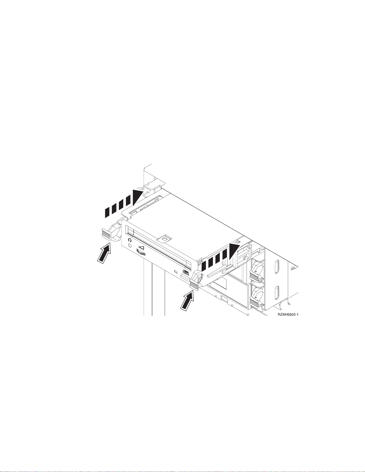
__ 14. Refer to Figure 41 and support the bottom of the removable media device
assembly as you slide it half way into the next available position. Do not
push it any further.
__ 15. Select option 2 (Install device for the action to be performed).
__ 16. Set the time delay for one minute.
01
Press the Enter key.
Note: Watch the light on the right side of the removable media devices. If
the light comes on and begins to blink rapidly, you have nine
seconds to slide the removable media device into place.
__ 17. When the light starts blinking, slide the removable media device in until it
seats properly. Push both blue handles in at the same time to lock the
removable media device into place.
Figure 41. Installing removable media
__ 18. The green light will stop blinking and remain on solid when you properly
installed the removable media device.
__ 19. Return to the console and wait until the Concurrent Maintenance Results
display appears.
Press the Enter key.
__ 20. When the Hardware Service Manager display appears, press F6 to print the
configuration list if you have a printer. You or a service representative may
refer to the configuration list in the future.
__ 21. Install the front cover for the expansion unit.
__ 22. Press F12 twice and press the Enter key to return to the AS/400 Main
menu.
The installation of the removable media device is complete.
60 Setting Up Your 5065 or 5066 Expansion Unit V4R5
Page 73

NonConcurrent procedure (system-unit powered off)
__ 1. If you have installed logical partitions on your system-unit, refer to the
AS/400 Information Center. At the AS/400 Information Center you can
find instructions on powering down a system with logical partitions.
__ 2. Ensure that all jobs are complete.
__ 3. When all jobs are complete, type on an AS/400 command line and press
the Enter key:
pwrdwnsys *immed
__ 4. When you have completely powered down the system–unit, power off all
PCs and devices, such as printers and displays, that are connected to the
system-unit.
__ 5. Unplug any power cords, such as printers and displays, from electrical
outlets.
__ 6. Unplug the power cord for the expansion unit from the electrical outlet.
__ 7. Refer to Figure 42 and use latch that is shown at A to open the front
cover.
__ 8. If needed, use the latch that is shown at B to remove the front cover.
Figure 42. Opening the front cover door
__ 9. Attach the disposable wrist strap to prevent electrostatic discharge from
damaging a device.
Notes:
a. The 2209 Disposable Wrist Strap is for static control. It will not increase
nor decrease your risk of receiving electric shock when using or
working on electrical equipment. Follow the same precautions you
would use without the wrist strap.
Appendix D. Installing removable media devices in the 5065 Expansion Unit 61
Page 74
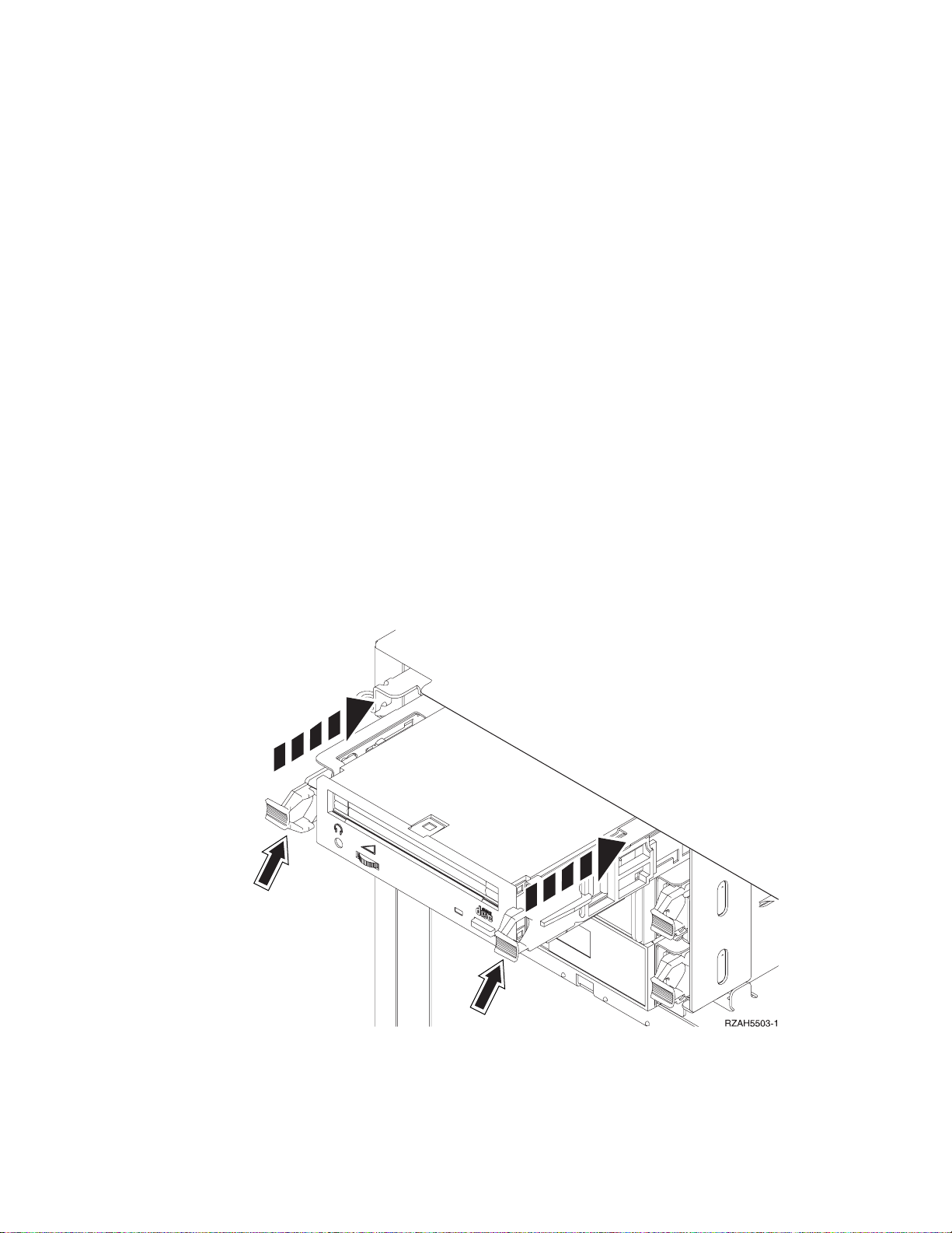
b. If the disposable wrist strap appears damaged, discard the wrist strap
immediately and contact your dealer for a replacement. Do not
continue until a new wrist strap is available.
c. When you unroll the wrist strap, remove the liner from the copper foil
at the end.
d. Attach the copper foil to an exposed, unpainted metal surface on the
frame of the 5065 Expansion Unit (electrical ground).
__ 10. Attention: Removable media devices are fragile. Handle with care.
Be sure to use the wrist strap provided. Place one end of the wrist strap
around your wrist and connect the opposite end to your system-unit.
__ 11. Pull out the removable media filler bezel.
__ 12. Remove the long plastic connector cover.
__ 13. Find the package that contains the new removable media device assembly
and remove it from the static-protective package.
__ 14. Hold the removable media device upright and pull both blue handles on
both sides of the removable media device toward you.
__ 15. Refer to Figure 43 and align the removable media device assembly with the
next available slot.
Note: Support the bottom of the removable media device assembly as you slide it
into place. Do not hold the removable media device by the blue handles.
__ 16. Slide it into the expansion unit until it stops.
__ 17. Push both blue handles in at the same time to lock the removable media
device into place.
Figure 43. Installing removable media
__ 18. Do you have any other devices to install?
No Yes
62 Setting Up Your 5065 or 5066 Expansion Unit V4R5
Page 75
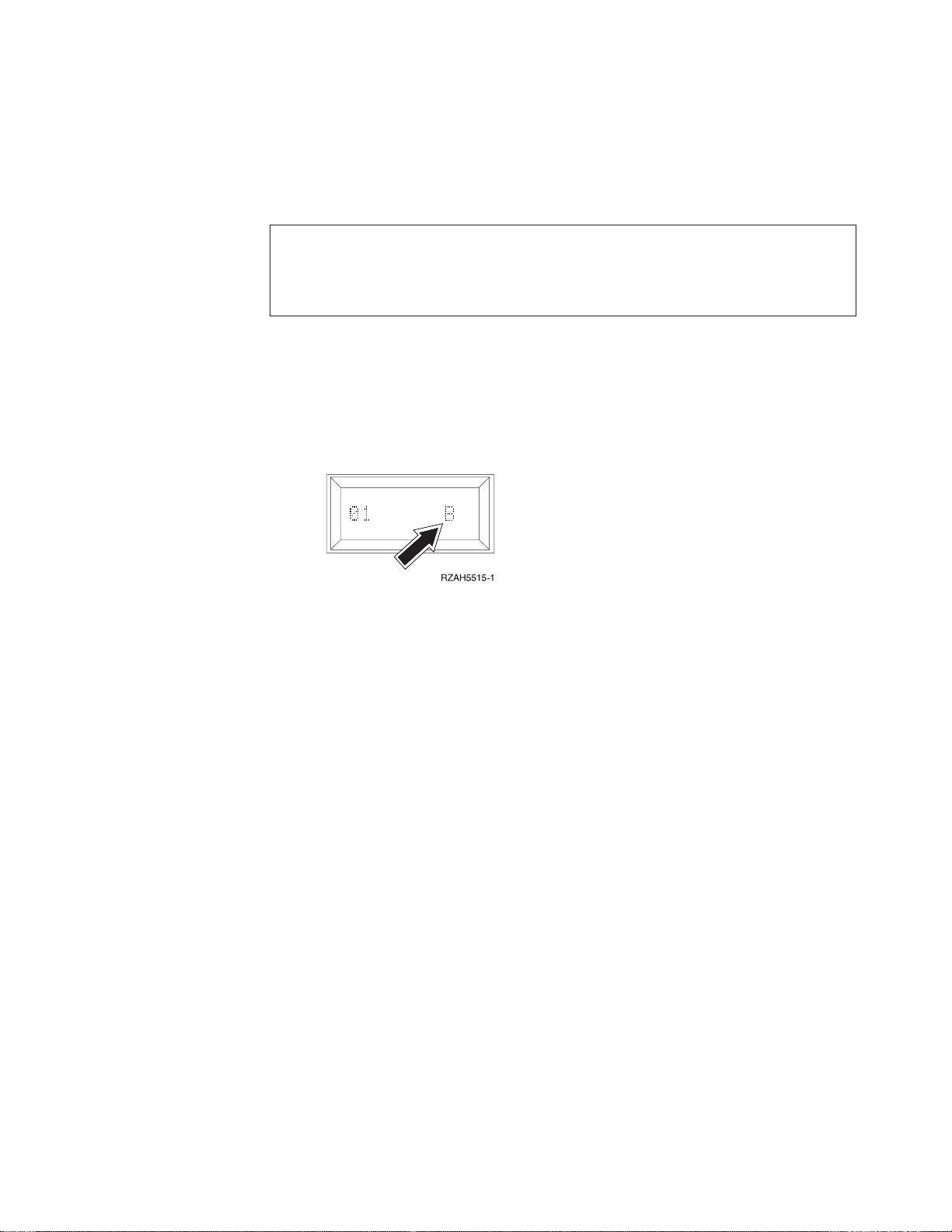
↓
If you have another device such as a tape unit or a CD-ROM drive,
refer to the instructions that came with that device.
__ 19. Install the front cover on the expansion unit.
DANGER
An electrical outlet that is not correctly wired could place hazardous voltage
on metal parts of the system or the products that attach to the system. It is the
customer’s responsibility to ensure that the outlet is correctly wired and
grounded to prevent an electrical shock. (RSFTD201)
__ 20. Plug the following power cords into an electrical outlet.
v Expansion unit
v System-unit console
__ 21. Plug in and power on all attached devices, such as printers and displays.
__ 22. Look at the Function/Data display on the system-unit control panel. Does
a B appear in the Function/Data display?
Yes No
↓ Do the following:
a. Press the Up or Down select push button until 02 appears in
the Function/Data display.
b. Press the Enter push button on the control panel.
c. Press the Up or Down select push button until B appears in the
Function/Data display.
d. Press the Enter push button on the control panel.
e. Press the Up or Down select push button until 01 appears in
the Function/Data display.
f. Press the Enter push button on the control panel.
g. Is the IPL mode Normal?
Yes No
↓ Press the mode button until a lit mode light indicates
that the action mode is Normal. Go to step 24.
h. Go to step 24.
__ 23. Make sure that the IPL mode is in Normal mode. If it is not, press the
mode button until a lit mode light indicates that the action mode is
Normal.
__ 24. Power on the workstation or PC that is console for your system.
__ 25. Press the power button to power on your AS/400 system unit.
__ 26. Sign on the AS/400 system-unit. Ensure that you have service tools
authority.
__ 27. Do the following to verify your removable media device configuration:
Appendix D. Installing removable media devices in the 5065 Expansion Unit 63
Page 76

a. On an AS/400 command line, type:
DSPHDWRSC *AHW
Press the Enter key.
b. When the Display All Hardware Resources display appears, type 7 in
the Opt column next to the feature number for the device you just
installed.
Press the Enter Key.
If the system does not list the tape unit, ensure that you have properly
installed the tape unit.
c. If you have a printer, print the configuration list. Place the
configuration list in Basic System Operation, Administration, and Problem
Handling, SC41-5206-04.
Note: To print the hardware resources list, press F6 twice.
d. Return to the AS/400 Main menu by pressing F3.
__ 28. For information on how to make your removable media device operational,
go to the AS/400 Information Center.
The installation of the removable media device is complete.
64 Setting Up Your 5065 or 5066 Expansion Unit V4R5
Page 77

Notices
This information was developed for products and services offered in the U.S.A.
IBM may not offer the products, services, or features discussed in this document in
other countries. Consult your local IBM representative for information on the
products and services currently available in your area. Any reference to an IBM
product, program, or service is not intended to state or imply that only that IBM
product, program, or service may be used. Any functionally equivalent product,
program, or service that does not infringe any IBM intellectual property right may
be used instead. However, it is the user’s responsibility to evaluate and verify the
operation of any non-IBM product, program, or service.
IBM may have patents or pending patent applications covering subject matter
described in this document. The furnishing of this document does not give you
any license to these patents. You can send license inquiries, in writing, to the
following address:
IBM Director of Licensing
IBM Corporation
500 Columbus Avenue
Thornwood, NY 10594
U.S.A.
For license inquiries regarding double-byte (DBCS) information, contact the IBM
Intellectual Property Department in your country or send inquiries, in writing, to:
IBM World Trade Asia Corporation
Licensing
2-31 Roppongi 3-chome, Minato-ku
Tokyo 106, Japan
The following paragraph does not apply to the United Kingdom or any other
country where such provisions are inconsistent with local law:
INTERNATIONAL BUSINESS MACHINES CORPORATION PROVIDES THIS
PUBLICATION “AS IS” WITHOUT WARRANTY OF ANY KIND, EITHER
EXPRESS OR IMPLIED, INCLUDING, BUT NOT LIMITED TO, THE IMPLIED
WARRANTIES OF NON-INFRINGEMENT, MERCHANTABILITY OR FITNESS
FOR A PARTICULAR PURPOSE. Some states do not allow disclaimer of express or
implied warranties in certain transactions, therefore, this statement may not apply
to you.
This information could include technical inaccuracies or typographical errors.
Changes are periodically made to the information herein; these changes will be
incorporated in new editions of the publication. IBM may make improvements
and/or changes in the product(s) and/or the program(s) described in this
publication at any time without notice.
Information concerning non-IBM products was obtained from the suppliers of
those products, their published announcements or other publicly available sources.
IBM has not tested those products and cannot confirm the accuracy of
performance, compatibility or any other claims related to non-IBM products.
Questions on the capabilities of non-IBM products should be addressed to the
suppliers of those products.
© Copyright IBM Corp. 1999, 2000 65
Page 78

If you are viewing this information softcopy, the photographs and color
illustrations may not appear.
The drawings and specifications contained herein shall not be reproduced in whole
or in part without the written permission of IBM.
IBM has prepared this publication for use by customer personnel for operating and
planning for the specific machines indicated. IBM makes no representations that it
is suitable for any other purpose.
Electronic Emission Notices
Federal Communications Commission (FCC) Statement
Note: This equipment has been tested and found to comply with the limits for a
Class A digital device, pursuant to Part 15 of the FCC Rules. These limits are
designed to provide reasonable protection against harmful interference when the
equipment is operated in a commercial environment. This equipment generates,
uses, and can radiate radio frequency energy and, if not installed and used in
accordance with the instruction manual, may cause harmful interference to radio
communications. Operation of this equipment in a residential area is likely to cause
harmful interference, in which case the user will be required to correct the
interference at his own expense.
Properly shielded and grounded cables and connectors must be used in order to
meet FCC emission limits. IBM is not responsible for any radio or television
interference caused by using other than recommended cables and connectors or by
unauthorized changes or modifications to this equipment. Unauthorized changes
or modifications could void the user’s authority to operate the equipment.
This device complies with Part 15 of the FCC rules. Operation is subject to the
following two conditions: (1) this device may not cause harmful interference, and
(2) this device must accept any interference received, including interference that
may cause undesired operation.
Responsible Party:
International Business Machines Corporation
New Orchard Road
Armonk, NY 10504
Telephone: 1-919-543-2193
Industry Canada Compliance Statement
This Class A digital apparatus meets the requirements of the Canadian
Interference-Causing Equipment Regulations.
Avis de conformitéàla réglementation d’Industrie Canada
Cet appareil numérique de la classe A respecte toutes les exigences du Règlement
sur le matériel brouilleur du Canada.
European Community Compliance Statement
66 Setting Up Your 5065 or 5066 Expansion Unit V4R5
Page 79

Trademarks
This product is in conformity with the protection requirements of EU Council
Directive 89/336/EEC on the approximation of the laws of the Member States
relating to electromagnetic compatibility. IBM cannot accept responsibility for any
failure to satisfy the protection requirements resulting from a non-recommended
modification of the product, including the fitting of non-IBM option cards.
Australia and New Zealand Class A Statement
Attention: This is a Class A product. In a domestic environment this product may
cause radio interference in which case the user may be required to take adequate
measures.
The following terms are trademarks of the International Business Machine
Corporation in the United States, or other countries, or both:
AS/400
AS/400e series
IBM
OS/400
PowerPC
Java is a registered trademark of Sun Microsystems, Inc.
Other company, product, and service names, may be trademarks or service marks
of others.
Notices 67
Page 80

68 Setting Up Your 5065 or 5066 Expansion Unit V4R5
Page 81

Readers’ Comments — We’d Like to Hear from You
AS/400e
Setting Up Your 5065 or 5066 Expansion Unit
Publication No. SA41-5146-01
Overall, how satisfied are you with the information in this book?
Very Satisfied Satisfied Neutral Dissatisfied Very
Dissatisfied
Overall satisfaction hhhhh
How satisfied are you that the information in this book is:
Very Satisfied Satisfied Neutral Dissatisfied Very
Dissatisfied
Accurate hhhhh
Complete hhhhh
Easy to find hhhhh
Easy to understand hhhhh
Well organized hhhhh
Applicable to your tasks hhhhh
Please tell us how we can improve this book:
Thank you for your responses. May we contact you? h Ye s h No
When you send comments to IBM, you grant IBM a nonexclusive right to use or distribute your comments in any
way it believes appropriate without incurring any obligation to you.
Name Address
Company or Organization
Phone No.
Page 82

___________________________________________________________________________________________________
Readers’ Comments — We’d Like to Hear from You
SA41-5146-01
_________________________________________________________________________________________
Fold and Tape Please do not staple Fold and Tape
NO POSTAGE
NECESSARY
IF MAILED IN THE
UNITED STATES
Cut or Fold
Along Line
BUSINESS REPLY MAIL
FIRST-CLASS MAIL PERMIT NO. 40 ARMONK, NEW YORK
POSTAGE WILL BE PAID BY ADDRESSEE
IBM CORPORATION
ATTN DEPT 542 IDCLERK
3605 HWY 52 N
ROCHESTER MN 55901-7829
_________________________________________________________________________________________
Fold and Tape Please do not staple Fold and Tape
SA41-5146-01
Cut or Fold
Along Line
Page 83

Page 84

Printed in the United States of America
on recycled paper containing 10%
recovered post-consumer fiber.
SA41-5146-01
Page 85

Spine information:
AS/400e Setting Up Your 5065 or 5066 Expansion Unit V4R5 Version 4
 Loading...