

Page 1

40/80 GB DLT
Internal Tape D rive
U se r 's G u id e
Be sure to read the important
maintenance information on page 2-1.
OPTIONS
by IBM
Page 2

Note: Before using this information and the product it supports, be sure to read
the information under Appendix F, “Product warranty and notices” on page 2-8.
Second Edition (April 2000)
The following paragraph does not apply to the United Kingdom or any country where such
provisions are inconsistent with local law: INTERNATIONAL BUSINESS MACHINES
CORPORATION PROVIDES THIS PUBLICATION “AS IS” WITHOUT WARRANTY OF
ANY KIND, EITHER EXPRESS OR IMPLIED, INCLUDING, BUT NOT LIMITED TO, THE
IMPLIED WARRANTIES OF MERCHANTABILITY OR FITNESS FOR A PARTICULAR
PURPOSE. Some states do not allow disclaimer of express or implied warranties in certain
transactions, therefore, this statement may not apply to you.
This publication could include technical inaccuracies or typographical errors. Changes are
periodically made to the information herein; these changes will be incorporated in new editions of
the publication. IBM may make improvements and/or changes in the product(s) and/or the
program(s) described in this publication at any time.
This publication was developed for products and services offered in the United States of America.
IBM may not offer the products, services, or features discussed in this document in other
countries, and the information is subject to change without notice. Consult your local IBM
representative for information on the products, services, and features available in your area.
Requests for technical information about IBM products should be made to your IBM reseller or
IBM marketing representative.
Copyright International Business Machines Corporation 1999, 2000. All rights reserved.
Note to U.S. Government Users — Documentation related to restricted rights — Use, duplication
or disclosure is subject to restrictions set forth in GSA ADP Schedule Contract with IBM Corp.
Page 3

Contents
Safety: Read first ................................ iv
Registering your option ............................ v
About this book ................................ v
Part 1: Installation, use, and maintenance guide ........ 1-1
Part 2: Appendixes ........................... 2-1
Appendix A. Maintaining your tape drive ................. 2-1
Appendix B. Power-on self-test (POST) sequence .............. 2-2
Appendix C. Product specifications . . . . . . . . . . . . . . . . . . . . . 2-3
Appendix D. Problem solving . . . . . . . . . . . . . . . . . . . . . . . . 2-4
Appendix E. Help and service information ................. 2-6
Online technical support ............................ 2-6
Telephone technical support .......................... 2-6
Appendix F. Product warranty and notices ................. 2-8
Warranty Statements . . . . . . . . . . . . . . . . . . . . . . . . . . . . . . 2-8
Notices . . . . . . . . . . . . . . . . . . . . . . . . . . . . . . . . . . . . 2-17
Trademarks . . . . . . . . . . . . . . . . . . . . . . . . . . . . . . . . . . 2-17
Electronic emission notices .......................... 2-18
Copyright IBM Corp. 1999, 2000 iii
Page 4
Safety: Read first
Before installing this product, read the Safety Information.
Antes de instalar este produto, leia as Informações de
Segurança.
Læs sikkerhedsforskrifterne, før du installerer dette produkt.
Ennen kuin asennat tämän tuotteen, lue turvaohjeet kohdasta
Avant d'installer ce produit, lisez les consignes de sécurité.
Vor der Installation dieses Produkts die Sicherheitshinweise
Prima di installare questo prodotto, leggere le Informazioni
Lees voordat u dit product installeert eerst de
Les sikkerhetsinformasjonen (Safety Information) før du
Před instalací tohoto produktu si přečtěte příručku bezpečnostních instrukcí.
Safety Information.
lesen.
sulla Sicurezza
veiligheidsvoorschriften.
installerer dette produktet.
Antes de instalar este produto, leia as Informações sobre
Segurança.
iv 40/80 GB DLT Internal Tape Drive
Page 5
Antes de instalar este producto lea la información de
Läs säkerhetsinformationen innan du installerar den här
Pred inštaláciou tohto zariadenia si pečítaje Bezpečnostné predpisy.
seguridad.
produkten.
Registering your option
Thank you for purchasing OPTIONS by IBM. Please take a few moments to register
your product and provide us with information that will help IBM to better serve you in
the future. Your feedback is valuable to us in developing products and services that
are important to you, as well as in developing better ways to communicate with you.
Register your option on the IBM Web site at:
http://www.ibm.com/pc/register
IBM will send you information and updates on your registered product unless you
indicate on the Web site questionnaire that you do not want to receive further
information.
About this book
This manual contains information on the IBM 40/80 GB DLT Internal Tape Drive. It
is divided into the following parts:
Part 1: Installation, use, and maintenance guide
This section contains the product description, installation and operating
instructions, and maintenance information in the following languages:
English, German, French, Spanish, Italian, Brazilian Portuguese, and
Japanese.
Part 2: Appendixes
Be sure to retain your proof of purchase. It might be required for warranty service.
Note: The illustrations in this manual might be slightly different from your
hardware.
This section contains power-on self-test sequence, problem-solving,
service, warranty, and notice information.
v
Page 6

vi 40/80 GB DLT Internal Tape Drive
Page 7

Part 1: Installation, use, and maintenance
guide
This guide contains product description, hardware and software installation
instructions, and product use and maintenance information. For information on solving
problems, see Appendix D, “Problem solving” on page 2-4.
Product description
The 40/80 GB1 DLT Internal Tape Drive is a fast/wide Ultra-2 (low voltage
differential) tape drive for backing up and restoring data and archiving files. These
files can include multimedia, imaging, transaction processing, large databases, and
other storage-intensive applications. Each tape cartridge can store up to 40 GB of data
(uncompressed), or up to 80 GB of data (compressed), assuming a 2:1 compression
ratio.
In addition to this book, the option package contains:
IBM 40/80 GB DLT Internal Tape Drive
Mounting screws
Jumpers
Data cartridge
Backup application CDs (trial versions)
Safety Information manual
Contact your place of purchase if an item is missing or damaged. Be sure to retain
your proof of purchase and packing material. They might be required to receive
warranty service.
Software description
The 40/80 GB DLT Internal Tape Drive includes trial-version backup application CDs.
These CDs contain popular backup and restore applications for Microsoft Windows
NT, Novell NetWare, and other operating systems. You can install the application
you choose for your computer system by following the installation instructions that
come with the CD you select. However, these trial versions of the software expire
after 30 or 90 days, depending on the application you use.
You can use the trial period to determine the best application for your specific
computer configuration. For information on purchasing a permanent installation copy
of the desired tape drive backup application, go to the IBM tape drive Web site at
1
GB equals approximately 1 000 000000 bytes.
Copyright IBM Corp. 1999, 2000
1-1
Page 8

http://www.ibm.com/pc/us/solutions/accessories/tapedrives.html and follow the software
links.
The CDs also contain backup applications that are used with other products but are not
applicable to the 40/80 GB DLT Internal Tape Drive. Supported tape drive
configurations can be found on the IBM Netfinity Server Compatibility Web page at
http://www.ibm.com/pc/compat
Installation requirements
To install this drive, you must have the following:
Low voltage differential (Ultra2) SCSI host adapter, or a single-ended (SE) 3
SCSI host adapter
Documentation for your computer, SCSI bus adapter, or external enclosure
An Ultra2 LVD active terminator if you are installing the tape drive at the end of
an Ultra2 LVD SCSI device chain
2
An SE active terminator if you are installing the tape drive at the end of an SE
SCSI device chain
3
Phillips head and flat blade screwdrivers for the mounting screws, and for
opening your computer
Flat-nose pliers (optional) to install and remove jumpers
An available 5.25-inch drive bay
Installing the drive
This section contains information on installing the tape drive in IBM servers and in
other computers.
2
This tape drive can be installed on a single-ended (SE) SCSI device chain, but doing so might
limit the performance of the drive.
3
SCSI termination might be provided with your computer or SCSI adapter. Refer to the
documentation that comes with your computer or SCSI adapter for more information.
4
If you are using a Netfinity 8500, 8500R, or 7000 server, you must install the tape drive in a
SCSI external storage enclosure such as the IBM 3551-001 or IBM 3503-BOX.
1-2 40/80 GB DLT Internal Tape Drive
Page 9

Installing the drive in IBM servers
The tape drive is compatible with the Netfinity 8500 or 8500R4, Netfinity 70008,
Netfinity 5500, and Netfinity 5000 servers. For instructions on installing the tape
drive in a server, go to the “Installing Internal Drives” section in the server’s User’s
Handbook and follow the directions for “Installing a 5.25-inch Removable-Media
Drive.”
Note: The server User’s Handbook instructions refer specifically to installing a
half-high drive in a single bay in the server. Your tape drive is a full-high drive
and must be installed in both drive bays in the server.
Part 1: Installation, use, and maintenance guide 1-3
Page 10

Installing the drive in other computers
Follow these steps to install the tape drive in other computers.
Step 1. Selecting a SCSI ID
Each device on a SCSI bus must have a unique SCSI ID. You can select a SCSI ID
from 0 to 6 for the tape drive. The SCSI ID must be supported by your SCSI adapter.
Refer to your SCSI adapter documentation for the range and the relative priority of the
IDs supported. The tape drive is shipped with the SCSI ID preset to 5.
Follow these guidelines to select a SCSI ID:
Assign the tape drive to one of the higher priority IDs available (0–6).
Assign the lower priority ID numbers (8–15) to those devices that are most often
used or are faster than other devices in the chain.
Do not assign an ID of 7, because this is usually used as the SCSI adapter ID.
Depending on your computer, there are several ways to view your current SCSI ID
settings:
For many IBM computers, press F1 during the startup after the memory check
completes. Other adapters show SCSI settings when you press Ctrl+A. Check
the documentation that comes with your computer or SCSI adapter for
information on how to view configuration information.
Use SCSI adapter utility programs, if available.
Inspect the installed SCSI devices to see how the jumpers that determine the IDs
are set.
Step 2. Preparing for installation
To prepare for installation:
1. Turn off all attached devices. Turn off the computer. Unplug the power cords
for the computer and all attached devices; then open the computer. For specific
information on opening your computer, refer to the documentation that comes
with your computer.
Attention: Tape drives are sensitive to static electricity discharge. The drives
are wrapped in a static-protective bag to prevent damage.
2. Before opening the static-protective bag containing the tape drive, touch the bag
to an unpainted metal surface on the computer for at least two seconds. Remove
the drive from the static-protective bag. If you must put the drive down, place
the drive on the static-protective bag. Do not touch any exposed components of
the tape drive. Instead, handle it carefully by the edges.
1-4 40/80 GB DLT Internal Tape Drive
Page 11
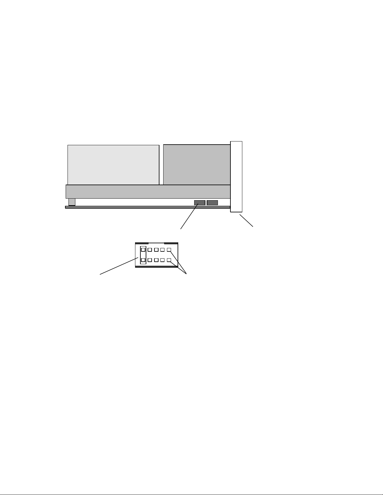
Step 3. Setting the SCSI ID, termination, and parity
Use the following illustration to locate the SCSI configuration jumper blocks.
SCSI ID Connector Block
A jumper must always be placed across Pin Pair 9 / 10 if any
SCSI ID other than the default (5) is selected.
If the tape drive is the last device on the SCSI bus, the bus must be terminated at the
drive.Some SCSI cables provide self termination and do not require terminators.To
terminate the bus at the drive, attach a SCSI terminator (not provided) to the drive
connector before attaching the SCSI cable.
Most SCSI adapters provide termination power. However, if your SCSI adapter does
not provide termination power, you must place a jumper in the enable termination
power position on the jumper block.Attach a SCSI terminator (not provided)
to the SCSI connector on the drive. For more information, refer to the documentation
that comes with your computer or SCSI adapter.
If you install the tape drive in an SCSI external storage enclosure such as the IBM
3503-BOX storage enclosure, and the enclosure is at the end of the SCSI bus, refer to
your enclosure documentation for information on termination.
Review the information that comes with your computer regarding parity generation. If
your system does not generate parity, you can disable parity checking by placing a
jumper in the disable parity position on the jumper block.
Pin Pair 1 / 2
Front Bezel
Part 1:Installation, use, and maintenance guide1-5
Page 12

If you choose the default SCSI address of 5, proceed to Step 4. If you need to change
the SCSI address, use the SCSI ID jumper block to set your SCSI ID.Remove
and reposition jumpers to set the ID. If necessary, use a pair of flat-nose pliers to
remove the jumpers. The following illustration shows how to set the jumper block for
each ID. Use the jumpers that come with your tape drive.
102
3
7
11
12
13
54
98
6
10
14 15
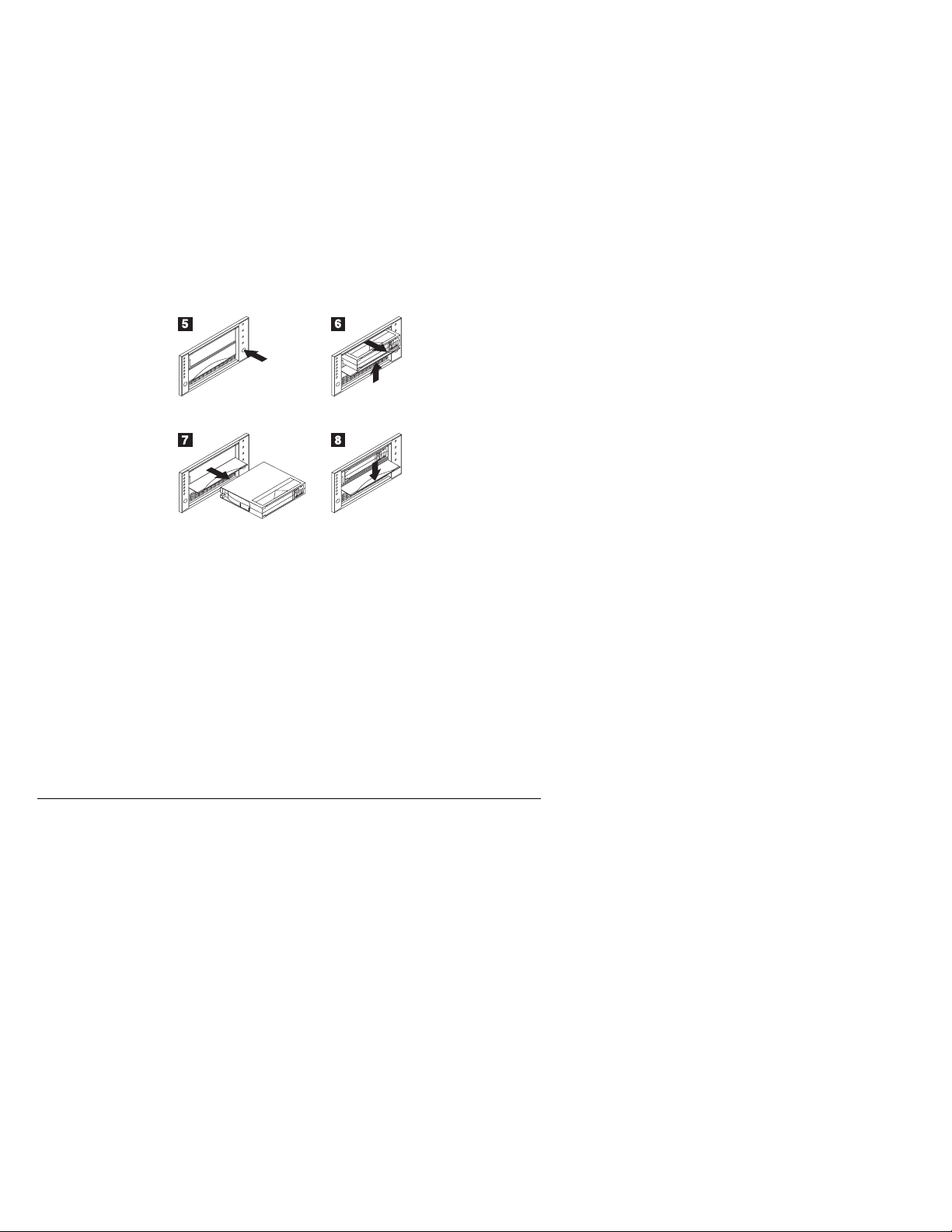
Step 4. Mounting the drive
Mount the tape drive; then attach the SCSI and power cables to it. If there is
insufficient working space to attach the connectors after mounting the drive, attach the
cables first (see “Step 5. Attaching cables” on page 1-19). To mount the drive:
1. Locate an available 5.25-inch bay or space in your computer to mount the tape
drive. Remove the cover plate from the bay selected. Place the drive
horizontally or vertically.
2. Align the drive-bay screw holes with the threaded holes in the drive housing.
When you mount the tape drive, follow these guidelines:
Ensure that no objects such as screw heads, cables, or adjacent devices are
pressing against the frame.
Ensure that nothing blocks the ventilation slots on the bottom and rear of the
tape drive.
3. Insert a screw through each of the drive-bay holes into the threaded holes in the
drive and tighten the screws with a screwdriver. Use only the screws that come
with the tape drive. Other screws might be too long and cause electrical shorts.
Step 5. Attaching cables
The rear tape drive connections are:
.1/ SCSI cable connector
.2/ Power connector
1-6 40/80 GB DLT Internal Tape Drive
Page 13

To attach the SCSI and power cables to the tape drive:
1. Locate the SCSI cable on your computer (a 68-pin (wide) ribbon cable with one
end connected to the SCSI adapter) and find the next available connector that is
farthest from the adapter. Use all empty bus connectors beginning with the one
farthest from the adapter to ensure better signal quality.
Note: The SCSI adapter might be part of the computer system board or might be
an adapter installed in an expansion slot.
2. Attach the SCSI cable from your computer to the tape drive 68-pin SCSI
connector .1/. The SCSI cable connector at the end of the SCSI cable will
attach to the drive only one way. Do not force the cable onto the drive.
Attention: Do not force the power cable into the tape drive power connector. If
the power cable is upside down and you force the connection, you might damage
the drive.
3. Connect the power cable connector to the four-pin connector .2/ on the tape
drive as shown in the illustration. If all the power cables are in use, purchase a
dc Y-splitter cable, which is available at most electronics stores, and split a
connection to make a connection available for the tape drive.
Step 6. Completing the installation
Check your work before closing the computer.
1. Be sure that the power and SCSI connectors are securely attached. Be sure that
the cables are neatly routed.
2. Replace the computer cover and secure it in place. Reconnect the power cords
and cables.
Step 7. Turning on the device
Turn on all attached devices; then turn on your computer. The tape drive performs a
power-on self-test (POST) within 15 seconds and then performs a drive reset.
Step 8. Updating the configuration
For most computers, the configuration-setup utility program automatically recognizes
the new tape drive. However, you might have to provide information about your
system changes after you restart your computer.
Ensure that the appropriate advanced SCSI programming interface (ASPI) device
drivers are installed to support the tape drive. Device drivers are usually provided
with the SCSI adapter.
If your computer does not recognize the tape drive after startup or you receive startup
errors, run the configuration-setup utility program as described in the documentation
that comes with your computer.
Part 1: Installation, use, and maintenance guide 1-7
Page 14
If all the indicators on either side of the tape drive blink in unison, there is a problem
with the tape drive. Press the Unload button on the right side of the drive front panel
to eject any tape that might be inserted and to reset the drive. If the problem persists,
turn off the computer; then turn it back on. If the problem continues, see
Appendix D, “Problem solving” on page 2-4 for further steps.
Step 9. Installing backup and restore software
To use the drive, you must install an appropriate backup and restore application for
your computer operating system. If you are using software not included in the option
package, follow the directions that come with your software. If you are using the trial
software that comes with the option, insert a trial application CD into the CD-ROM
drive and follow the on-screen installation and operating instructions.
Using the drive
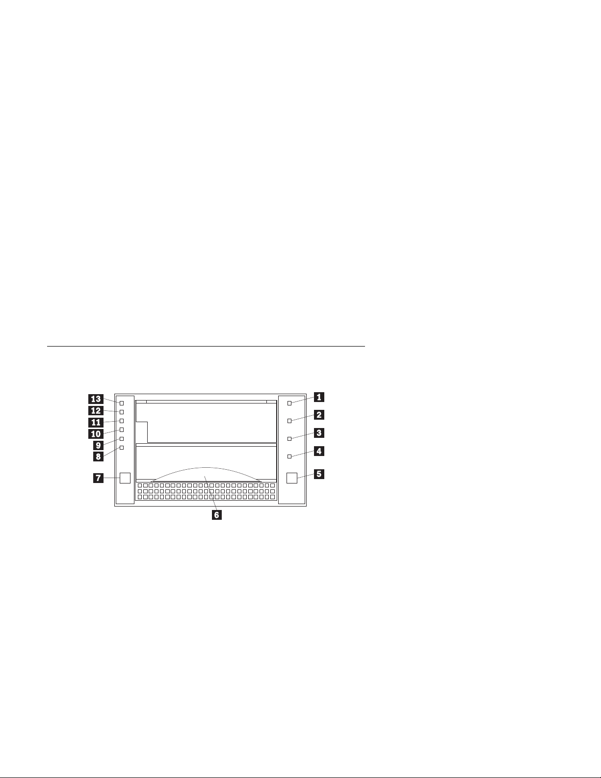
The illustration shows the drive front panel.
.1/-.4/ Status indicators
.5/ Unload button
.6/ Cartridge Insert/Release handle
.7/ Select button
.8/ Density Override indicator
.9/ Compress indicator
.1ð/-.13/ Tape Capacity indicators
1-8 40/80 GB DLT Internal Tape Drive
Page 15

Understanding the status indicators
The indicators on the right side of the drive front panel are:
.1/ Write Protect (orange): When this indicator is on, the tape is write
protected.
.2/ Tape in Use (yellow): When this indicator is blinking, the tape is in motion.
When this indicator lights steadily, the tape is loaded and ready for use.
.3/ Use Cleaning Tape (yellow): When this indicator is on, the drive head
needs cleaning or the tape is damaged. For instructions on cleaning the drive, go
to “Cleaning the drive” on page 1-13.
.4/ Operate Handle (green): When this indicator lights steadily, you can lift the
Cartridge Insert/Release handle. If the indicator is blinking, push the handle
down and wait for the indicator to stop blinking.
Using the controls
Use the controls listed below for unloading a tape, resetting the tape drive, inserting or
releasing a cartridge, or cycling through tape capacity options.
.5/ Unload: Press this button to unload a tape or to reset the tape drive.
.6/ Cartridge Insert/Release: Lift this handle to insert or remove a cartridge
when the Operate Handle indicator lights.
.7/ Select: When the Density Override indicator .8/ is flashing, you can press
this button to cycle through tape capacity options.
Reading the capacity indicators
The indicators on the left side of the front panel indicate current tape cartridge
capacity in gigabytes, as well as any change in capacity you have requested. The type
of data cartridge you use determines the capacities available for your selection. See
“Selecting recording capacity” on page 1-11 for instructions on selecting recording
capacity. See the “Maximum data capacity” table on page 2-3 for more details.
Note: Tape capacity cannot be changed mid-tape. To change tape capacity, the tape
must be rewritten from the beginning.
.8/ Density Override (yellow): When this indicator is lit, it indicates that you
used the Select button to change tape capacity.
.9/ Compress (yellow): When this indicator is lit, data compression is enabled.
.1ð/ 40.0 (yellow): When this indicator lights steadily, the tape is recorded at
40.0 GB capacity. When this indicator is blinking, it indicates that you requested
this capacity.
.11/ 35.0 (yellow): When this indicator lights steadily, the tape is recorded at
35.0 GB capacity. When this indicator is blinking, it indicates that you requested
this capacity.
Part 1: Installation, use, and maintenance guide 1-9
Page 16

.12/ 20.0 (yellow): When this indicator lights steadily, the tape is recorded at
20.0 GB capacity. When this light is blinking, it indicates that you requested this
capacity.
.13/ 10.0/15.0 (yellow): When this indicator lights steadily, the tape is recorded
at 10.0 GB or 15.0 GB capacity. When this indicator is blinking, it indicates you
requested this capacity.
If the indicators flash in unison, it indicates a tape drive hardware failure. Try to reset
the drive by following instructions given in “Resetting the drive” on page 1-14.
Selecting data cartridges
For writing data, use only DLT data cartridges. Any of the following data cartridges
are compatible with the tape drive and require no formatting or other media
conditioning before use. For maximum data rate and storage capacities, use the IBM
Data Cartridge (part number 59H3040) or Quantum DLTtape IV Cartridge.
IBM Data Cartridge (part number 59H3040) - 40 GB capacity (80 GB
compressed)
DLTtape III - 10 GB original capacity (20 GB compressed)
DLTtape IIIxt - 15 GB original capacity (30 GB compressed)
DLTtape IV - 40 GB original capacity (80 GB compressed)
Caring for tape cartridges
Use the following maintenance guidelines to properly handle your tape cartridges.
Do not carry loose cartridges in a box or other container that exposes them to
unnecessary physical shock.
Store each cartridge vertically in its protective case when you are not using it.
Do not drop or bump cartridge; this might dislodge or damage internal
components.
Avoid opening the cartridge door unnecessarily. Opening the cartridge door
might expose the tape to contamination or physical damage.
Do not allow anything to contact the tape medium or the tape leader. Dust or
skin oils can contaminate the tape and hinder performance.
Do not expose cartridges to moisture, direct sunlight, or condensation.
Maintain clean operating, working, and storage environments.
Do not place cartridges on or near devices that might produce magnetic fields,
such as computer monitors, motors, or video equipment. Such exposure can alter
or erase data on the tape. Magnetic fields are usually not a problem unless you
place a tape cartridge a few inches from a magnet or an electric motor.
Do not attempt to remove a tape cartridge from the tape system unless the
Operate Handle indicator is lit steadily. Overriding the system handle causes
damage to both the media and the tape drive.
1-10 40/80 GB DLT Internal Tape Drive
Page 17

The ambient operating temperature for the tape cartridge is 10°C to 40°C (50°F to
104°F) and the ambient operating relative humidity (noncondensing) is 20% to
80%. If storage or transportation of a tape cartridge has exposed it to conditions
outside these ambient values, allow the tape cartridge to acclimate to proper
operating conditions for a 24-hour period before using.
Place labels only in the front slide slot of the cartridge. Placing a label on the
top, bottom, sides, or rear of the cartridge might interfere with normal cartridge
operation and might damage other parts of the drive.
Do not use graphite pencils, water-soluble felt pens, or other debris-producing
writing instruments on your labels. Never use an eraser on a label; replace the
label.
Be sure to place unused cartridge labels in the protective box so that you do not
inadvertently pick them up along with the cartridge during subsequent usage. A
static electricity charge on a cartridge might cause a label to cling to the cartridge.
If you accidentally insert a label into the system along with a cartridge, the hub
reel and system gear might not mesh.
Follow all instructions for tape cartridge handling that come with your cartridges
or tape system.
Selecting recording capacity
You might want to decrease tape capacity for compatibility with older tape drives, or
increase capacity for enhanced performance. Insert a tape cartridge, and wait for tape
motion to stop and the Tape in Use indicator to light steadily. The capacity indicators
show the current tape capacity. If they are not lit, it means the tape is blank.
Press the Select button to change density. When the Density Override indicator is
blinking, you can press the Select button to change the recording capacity of the tape.
Press the Select button until the desired capacity indicator is flashing. The indicator
will continue flashing until the tape drive begins recording in the new capacity. Then,
the new capacity indicator lights steadily, and the original capacity indicator turns off.
Note: Your choice of capacities is limited by the data cartridge you use. See the
“Maximum data capacity” table on page 2-3.
Setting write protection on the cartridge
Part 1: Installation, use, and maintenance guide 1-11
Page 18

The front of the cartridge has an orange write-protect indicator .1/, and a
write-protect switch .2/ to prevent accidental erasure. Slide the switch to the right
to write-enable .3/ or to the left to write-protect.4/. You can change the
write-protect switch before or after inserting the tape. If you change the write-protect
switch while the tape is inserted, there is a delay of a few seconds before the Write
Protect indicator on the tape drive changes.
Note: Your backup/restore software might also provide write-protection for the
cartridge.
Loading and unloading data cartridges
Attention: Turning on the drive with a tape inserted and the handle unlatched
might damage the tape cartridge or tape drive.
When the yellow Tape in Use indicator is off and the green Operate Handle indicator
is on, the tape drive is ready to accept a cartridge. If a cartridge is present during
power-on self-test (POST) and the Cartridge Insert/Release handle is down, the tape
drive will automatically load the tape once POST has completed.
To load a cartridge:
.1/ Be sure the Operate Handle indicator is on. Lift the Cartridge Insert/Release
handle.
.2/ Position the cartridge with the write-protect switch facing you and to the right.
.3/ Insert the cartridge fully into the door.
.4/ Push the Cartridge Insert/Release handle down.
The tape drive loads the tape in approximately 20 seconds. The green Operate
Handle indicator turns off and the yellow Tape in Use indicator flashes to show the
tape is rewinding to the beginning. When the yellow Tape in Use indicator lights
steadily, the tape drive is ready for read and write operations.
To unload a cartridge:
1-12 40/80 GB DLT Internal Tape Drive
Page 19

.5/ Press the Unload button and wait for the green Operate Handle indicator to
light.
.6/ Lift the Cartridge Insert/Release handle up to pop the tape cartridge out.
.7/ Remove the tape cartridge from the drive.
.8/ Push the Cartridge Insert/Release handle down.
When you press the Unload button, the tape drive performs the following:
Completes any command in process
Writes any buffered information to tape
Rewinds the tape to the beginning
Turns the green Operate Handle indicator on
If an error occurs before or during the unloading process, the tape drive stops. To
clear the error, press the Unload button again.
Cleaning the drive
When the yellow Use Cleaning Tape indicator lights, the tape drive requires cleaning.
Clean the drive as soon as possible.
To clean the tape drive, insert an IBM Cleaning Cartridge (part number 59H3092) or
DLT Cleaning Tape. When cleaning is finished, the Use Cleaning Tape indicator
turns off and the tape drive beeps. Press the Unload button and lift the Cartridge
Insert/Release handle to remove the cleaning tape.
If the Use Cleaning Tape indicator does not turn off, it is possible that the cleaning
cartridge has been used more than 20 times. Replace the used cartridge with a new
one and repeat the cleaning process.
If the Use Cleaning Tape indicator lights while a data cartridge is in use and you
have recently cleaned your drive, back up your data onto a new cartridge. Discard the
original cartridge. It might be damaged.
Part 1: Installation, use, and maintenance guide 1-13
Page 20

Resetting the drive
The reset procedure rewinds the tape and clears the buffer of previous tape drive
commands and data. To reset the tape drive, press the Unload button, or turn the
computer off and back on again.
If you reset the tape drive while a cartridge is loaded, the tape rewinds to the
beginning. The reset might take as long as two minutes if the tape is positioned near
the end. After the drive has been reset, tape operation starts from the beginning of the
data cartridge. After resetting the drive, restart your backup tape software.
Packing the drive for shipping
If you are shipping the tape drive to another location or returning it for repair, pack
the tape drive in its original shipping container and packing materials.
Attention: To avoid damaging the tape drive, use the original shipping materials
when you ship it. Your proof of purchase might be required to receive warranty
service. If you are returning the tape drive for service, remove and keep all
cartridges, cables, and terminators.
1-14 40/80 GB DLT Internal Tape Drive
Page 21

Installation, use and maintenance guide
(Translate)
This guide contains product description, hardware and software installation
instructions, and product use and maintenance information.
Product description
The 40/80 GB5 DLT Internal Tape Drive is a fast/wide Ultra-2 (low voltage
differential) tape drive for backing up and restoring data and archiving files. These
files can include multimedia, imaging, transaction processing, large databases, and
other storage-intensive applications. Each tape cartridge can store up to 40 GB of data
(uncompressed), or up to 80 GB of data (compressed), assuming a 2:1 compression
ratio.
In addition to this book, the option package contains:
IBM 40/80 GB DLT Internal Tape Drive
Mounting screws
Jumpers
Data cartridge
Backup application CDs (trial versions)
Safety Information manual
Contact your place of purchase if an item is missing or damaged. Be sure to retain
your proof of purchase and packing material. They might be required to receive
warranty service.
Software description
The 40/80 GB DLT Internal Tape Drive includes trial-version backup application CDs.
These CDs contain popular backup and restore applications for Microsoft Windows
NT, Novell NetWare, and other operating systems. You can install the application
you choose for your computer system by following the installation instructions that
come with the CD you select. However, these trial versions of the software expire
after 30 or 90 days, depending on the application you use.
You can use the trial period to determine the best application for your specific
computer configuration. For information on purchasing a permanent installation copy
of the desired tape drive backup application, go to the IBM tape drive Web site at
http://www.ibm.com/pc/us/solutions/accessories/tapedrives.html and follow the software
links.
5
GB equals approximately 1 000 000000 bytes.
Part 1: Installation, use, and maintenance guide 1-15
Page 22

The CDs also contain backup applications that are used with other products but are not
applicable to the 40/80 GB DLT Internal Tape Drive. Supported tape drive
configurations can be found on the IBM Netfinity Server Compatibility Web page at
http://www.ibm.com/pc/compat
To install this drive, you must have the following:
Low voltage differential (Ultra2) SCSI host adapter, or a single-ended (SE) 3
SCSI host adapter
Documentation for your computer, SCSI bus adapter, or external enclosure
An Ultra2 LVD active terminator if you are installing the tape drive at the end of
an Ultra2 LVD SCSI device chain
6
An SE active terminator if you are installing the tape drive at the end of an SE
SCSI device chain
7
Phillips head and flat blade screwdrivers for the mounting screws, and for
opening your computer
Flat-nose pliers (optional) to install and remove jumpers
An available 5.25-inch drive bay
Installing the drive
This section contains information on installing the tape drive in IBM servers and in
other computers.
Installing the drive in IBM servers
The tape drive is compatible with the Netfinity 8500 or 8500R8, Netfinity 70008,
Netfinity 5500, and Netfinity 5000 servers. For instructions on installing the tape
drive in a server, go to the “Installing Internal Drives” section in the server’s User’s
Handbook and follow the directions for “Installing a 5.25-inch Removable-Media
Drive.”
Note: The server User’s Handbook instructions refer specifically to installing a
half-high drive in a single bay in the server. Your tape drive is a full-high drive
and must be installed in both drive bays in the server.
6
This tape drive can be installed on a single-ended (SE) SCSI device chain, but doing so might
limit the performance of the drive.
7
SCSI termination might be provided with your computer or SCSI adapter. Refer to the
documentation that comes with your computer or SCSI adapter for more information.
8
If you are using a Netfinity 8500, 8500R, or 7000 server, you must install the tape drive in a
SCSI external storage enclosure such as the IBM 3551-001 or IBM 3503-BOX.
1-16 40/80 GB DLT Internal Tape Drive
Page 23

Installing the drive in other computers
Follow these steps to install the tape drive in other computers.
Step 1. Selecting a SCSI ID
Each device on a SCSI bus must have a unique SCSI ID. You can select a SCSI ID
from 0 to 6 for the tape drive. The SCSI ID must be supported by your SCSI adapter.
Refer to your SCSI adapter documentation for the range and the relative priority of the
IDs supported. The tape drive is shipped with the SCSI ID preset to 5.
Follow these guidelines to select a SCSI ID:
Assign the tape drive to one of the higher priority IDs available (0–6).
Assign the lower priority ID numbers (8–15) to those devices that are most often
used or are faster than other devices in the chain.
Do not assign an ID of 7, because this is usually used as the SCSI adapter ID.
Depending on your computer, there are several ways to view your current SCSI ID
settings:
For many IBM computers, press F1 during the startup after the memory check
completes. Other adapters show SCSI settings when you press Ctrl+A. Check
the documentation that comes with your computer or SCSI adapter for
information on how to view configuration information.
Use SCSI adapter utility programs, if available.
Inspect the installed SCSI devices to see how the jumpers that determine the IDs
are set.
Step 2. Preparing for installation
To prepare for installation:
1. Turn off all attached devices. Turn off the computer. Unplug the power cords
for the computer and all attached devices; then open the computer. For specific
information on opening your computer, refer to the documentation that comes
with your computer.
Attention: Tape drives are sensitive to static electricity discharge. The drives
are wrapped in a static-protective bag to prevent damage.
2. Before opening the static-protective bag containing the tape drive, touch the bag
to an unpainted metal surface on the computer for at least two seconds. Remove
the drive from the static-protective bag. If you must put the drive down, place
the drive on the static-protective bag. Do not touch any exposed components of
the tape drive. Instead, handle it carefully by the edges.
Part 1: Installation, use, and maintenance guide 1-17
Page 24

Step 3. Setting the SCSI ID, termination, and parity
Use the following illustration to locate the SCSI configuration jumper blocks.
Front Bezel
Jumper on Pin Pair 3 / 4 enables
termination power (TERM PWR).
If the tape drive is the last device on the SCSI bus, the bus must be terminated at the
drive. Some SCSI cables provide self termination and do not require terminators. To
terminate the bus at the drive, attach a SCSI terminator (not provided) to the drive
connector before attaching the SCSI cable.
Most SCSI adapters provide termination power. However, if your SCSI adapter does
not provide termination power, you must place a jumper in the enable termination
power position on the jumper block.Attach a SCSI terminator (not provided)
to the SCSI connector on the drive. For more information, refer to the documentation
that comes with your computer or SCSI adapter.
If you install the tape drive in an SCSI external storage enclosure such as the IBM
3503-BOX storage enclosure, and the enclosure is at the end of the SCSI bus, refer to
your enclosure documentation for information on termination.
Review the information that comes with your computer regarding parity generation. If
your system does not generate parity, you can disable parity checking by placing a
jumper in the disable parity position on the jumper block.
1-18 40/80 GB DLT Internal Tape Drive
Page 25

If you choose the default SCSI address of 5, proceed to Step 4. If you need to change
the SCSI address, use the SCSI ID jumper block to set your SCSI ID.Remove
and reposition jumpers to set the ID. If necessary, use a pair of flat-nose pliers to
remove the jumpers. The following illustration shows how to set the jumper block for
each ID. Use the jumpers that come with your tape drive.
102
3
7
11
12
13
54
98
6
10
14 15
Step 4. Mounting the drive
Mount the tape drive; then attach the SCSI and power cables to it. If there is
insufficient working space to attach the connectors after mounting the drive, attach the
cables first (see “Step 5. Attaching cables”). To mount the drive:
1. Locate an available 5.25-inch bay or space in your computer to mount the tape
drive. Remove the cover plate from the bay selected. Place the drive
horizontally or vertically.
2. Align the drive-bay screw holes with the threaded holes in the drive housing.
When you mount the tape drive, follow these guidelines:
Ensure that no objects such as screw heads, cables, or adjacent devices are
pressing against the frame.
Ensure that nothing blocks the ventilation slots on the bottom and rear of the
tape drive.
3. Insert a screw through each of the drive-bay holes into the threaded holes in the
drive and tighten the screws with a screwdriver. Use only the screws that come
with the tape drive. Other screws might be too long and cause electrical shorts.
Step 5. Attaching cables
The rear tape drive connections are:
.1/ SCSI cable connector
.2/ Power connector
Part 1: Installation, use, and maintenance guide 1-19
Page 26

To attach the SCSI and power cables to the tape drive:
1. Locate the SCSI cable on your computer (a 68-pin (wide) ribbon cable with one
end connected to the SCSI adapter) and find the next available connector that is
farthest from the adapter. Use all empty bus connectors beginning with the one
farthest from the adapter to ensure better signal quality.
Note: The SCSI adapter might be part of the computer system board or might be
an adapter installed in an expansion slot.
2. Attach the SCSI cable from your computer to the tape drive 68-pin SCSI
connector .1/. The SCSI cable connector at the end of the SCSI cable will
attach to the drive only one way. Do not force the cable onto the drive.
Attention: Do not force the power cable into the tape drive power connector. If
the power cable is upside down and you force the connection, you might damage
the drive.
3. Connect the power cable connector to the four-pin connector .2/ on the tape
drive as shown in the illustration. If all the power cables are in use, purchase a
dc Y-splitter cable, which is available at most electronics stores, and split a
connection to make a connection available for the tape drive.
Step 6. Completing the installation
Check your work before closing the computer.
1. Be sure that the power and SCSI connectors are securely attached. Be sure that
the cables are neatly routed.
2. Replace the computer cover and secure it in place. Reconnect the power cords
and cables.
Step 7. Turning on the device
Turn on all attached devices; then turn on your computer. The tape drive performs a
power-on self-test (POST) within 15 seconds and then performs a drive reset.
Step 8. Updating the configuration
For most computers, the configuration-setup utility program automatically recognizes
the new tape drive. However, you might have to provide information about your
system changes after you restart your computer.
Ensure that the appropriate advanced SCSI programming interface (ASPI) device
drivers are installed to support the tape drive. Device drivers are usually provided
with the SCSI adapter.
If your computer does not recognize the tape drive after startup or you receive startup
errors, run the configuration-setup utility program as described in the documentation
that comes with your computer.
1-20 40/80 GB DLT Internal Tape Drive
Page 27
If all the indicators on either side of the tape drive blink in unison, there is a problem
with the tape drive. Press the Unload button on the right side of the drive front panel
to eject any tape that might be inserted and to reset the drive. If the problem persists,
turn off the computer; then turn it back on. If the problem continues, see
Appendix D, “Problem solving” on page 2-4 for further steps.
Step 9. Installing backup and restore software
To use the drive, you must install an appropriate backup and restore application for
your computer operating system. If you are using software not included in the option
package, follow the directions that come with your software. If you are using the trial
software that comes with the option, insert a trial application CD into the CD-ROM
drive and follow the on-screen installation and operating instructions.
Using the drive
The illustration shows the drive front panel.
.1/-.4/ Status indicators
.5/ Unload button
.6/ Cartridge Insert/Release handle
.7/ Select button
.8/ Density Override indicator
.9/ Compress indicator
.1ð/-.13/ Tape Capacity indicators
Part 1: Installation, use, and maintenance guide 1-21
Page 28

Understanding the status indicators
The indicators on the right side of the drive front panel are:
.1/ Write Protect (orange): When this indicator is on, the tape is write
protected.
.2/ Tape in Use (yellow): When this indicator is blinking, the tape is in motion.
When this indicator lights steadily, the tape is loaded and ready for use.
.3/ Use Cleaning Tape (yellow): When this indicator is on, the drive head
needs cleaning or the tape is damaged. For instructions on cleaning the drive, go
to “Cleaning the drive” on page 1-26.
.4/ Operate Handle (green): When this indicator lights steadily, you can lift the
Cartridge Insert/Release handle. If the indicator is blinking, push the handle
down and wait for the indicator to stop blinking.
Using the controls
Use the controls listed below for unloading a tape, resetting the tape drive, inserting or
releasing a cartridge, or cycling through tape capacity options.
.5/ Unload: Press this button to unload a tape or to reset the tape drive.
.6/ Cartridge Insert/Release: Lift this handle to insert or remove a cartridge
when the Operate Handle indicator lights.
.7/ Select: When the Density Override indicator .8/ is flashing, you can press
this button to cycle through tape capacity options.
Reading the capacity indicators
The indicators on the left side of the front panel indicate current tape cartridge
capacity in gigabytes, as well as any change in capacity you have requested. The type
of data cartridge you use determines the capacities available for your selection. See
“Selecting recording capacity” on page 1-24 for instructions on selecting recording
capacity. See the “Maximum data capacity” table on page 2-3 for more details.
Note: Tape capacity cannot be changed mid-tape. To change tape capacity, the tape
must be rewritten from the beginning.
.8/ Density Override (yellow): When this indicator is lit, it indicates that you
used the Select button to change tape capacity.
.9/ Compress (yellow): When this indicator is lit, data compression is enabled.
.1ð/ 40.0 (yellow): When this indicator lights steadily, the tape is recorded at
40.0 GB capacity. When this indicator is blinking, it indicates that you requested
this capacity.
.11/ 35.0 (yellow): When this indicator lights steadily, the tape is recorded at
35.0 GB capacity. When this indicator is blinking, it indicates that you requested
this capacity.
1-22 40/80 GB DLT Internal Tape Drive
Page 29

.12/ 20.0 (yellow): When this indicator lights steadily, the tape is recorded at
20.0 GB capacity. When this light is blinking, it indicates that you requested this
capacity.
.13/ 10.0/15.0 (yellow): When this indicator lights steadily, the tape is recorded
at 10.0 GB or 15.0 GB capacity. When this indicator is blinking, it indicates you
requested this capacity.
If the indicators flash in unison, it indicates a tape drive hardware failure. Try to reset
the drive by following instructions given in “Resetting the drive” on page 1-27.
Selecting data cartridges
For writing data, use only DLT data cartridges. Any of the following data cartridges
are compatible with the tape drive and require no formatting or other media
conditioning before use. For maximum data rate and storage capacities, use the IBM
Data Cartridge (part number 59H3040) or Quantum DLTtape IV Cartridge.
IBM Data Cartridge (part number 59H3040) - 40 GB capacity (80 GB
compressed)
DLTtape III - 10 GB original capacity (20 GB compressed)
DLTtape IIIxt - 15 GB original capacity (30 GB compressed)
DLTtape IV - 40 GB original capacity (80 GB compressed)
Caring for tape cartridges
Use the following maintenance guidelines to properly handle your tape cartridges.
Do not carry loose cartridges in a box or other container that exposes them to
unnecessary physical shock.
Store each cartridge vertically in its protective case when you are not using it.
Do not drop or bump cartridge; this might dislodge or damage internal
components.
Avoid opening the cartridge door unnecessarily. Opening the cartridge door
might expose the tape to contamination or physical damage.
Do not allow anything to contact the tape medium or the tape leader. Dust or
skin oils can contaminate the tape and hinder performance.
Do not expose cartridges to moisture, direct sunlight, or condensation.
Maintain clean operating, working, and storage environments.
Do not place cartridges on or near devices that might produce magnetic fields,
such as computer monitors, motors, or video equipment. Such exposure can alter
or erase data on the tape. Magnetic fields are usually not a problem unless you
place a tape cartridge a few inches from a magnet or an electric motor.
Do not attempt to remove a tape cartridge from the tape system unless the
Operate Handle indicator is lit steadily. Overriding the system handle causes
damage to both the media and the tape drive.
Part 1: Installation, use, and maintenance guide 1-23
Page 30

The ambient operating temperature for the tape cartridge is 10°C to 40°C (50°F to
104°F) and the ambient operating relative humidity (noncondensing) is 20% to
80%. If storage or transportation of a tape cartridge has exposed it to conditions
outside these ambient values, allow the tape cartridge to acclimate to proper
operating conditions for a 24-hour period before using.
Place labels only in the front slide slot of the cartridge. Placing a label on the
top, bottom, sides, or rear of the cartridge might interfere with normal cartridge
operation and might damage other parts of the drive.
Do not use graphite pencils, water-soluble felt pens, or other debris-producing
writing instruments on your labels. Never use an eraser on a label; replace the
label.
Be sure to place unused cartridge labels in the protective box so that you do not
inadvertently pick them up along with the cartridge during subsequent usage. A
static electricity charge on a cartridge might cause a label to cling to the cartridge.
If you accidentally insert a label into the system along with a cartridge, the hub
reel and system gear might not mesh.
Follow all instructions for tape cartridge handling that come with your cartridges
or tape system.
Selecting recording capacity
You might want to decrease tape capacity for compatibility with older tape drives, or
increase capacity for enhanced performance. Insert a tape cartridge, and wait for tape
motion to stop and the Tape in Use indicator to light steadily. The capacity indicators
show the current tape capacity. If they are not lit, it means the tape is blank.
Press the Select button to change density. When the Density Override indicator is
blinking, you can press the Select button to change the recording capacity of the tape.
Press the Select button until the desired capacity indicator is flashing. The indicator
will continue flashing until the tape drive begins recording in the new capacity. Then,
the new capacity indicator lights steadily, and the original capacity indicator turns off.
Note: Your choice of capacities is limited by the data cartridge you use. See the
“Maximum data capacity” table on page 2-3.
Setting write protection on the cartridge
1-24 40/80 GB DLT Internal Tape Drive
Page 31

The front of the cartridge has an orange write-protect indicator .1/, and a
write-protect switch .2/ to prevent accidental erasure. Slide the switch to the right
to write-enable .3/ or to the left to write-protect.4/. You can change the
write-protect switch before or after inserting the tape. If you change the write-protect
switch while the tape is inserted, there is a delay of a few seconds before the Write
Protect indicator on the tape drive changes.
Note: Your backup/restore software might also provide write-protection for the
cartridge.
Loading and unloading data cartridges
Attention: Turning on the drive with a tape inserted and the handle unlatched
might damage the tape cartridge or tape drive.
When the yellow Tape in Use indicator is off and the green Operate Handle indicator
is on, the tape drive is ready to accept a cartridge. If a cartridge is present during
power-on self-test (POST) and the Cartridge Insert/Release handle is down, the tape
drive will automatically load the tape once POST has completed.
To load a cartridge:
.1/ Be sure the Operate Handle indicator is on. Lift the Cartridge Insert/Release
handle.
.2/ Position the cartridge with the write-protect switch facing you and to the right.
.3/ Insert the cartridge fully into the door.
.4/ Push the Cartridge Insert/Release handle down.
The tape drive loads the tape in approximately 20 seconds. The green Operate
Handle indicator turns off and the yellow Tape in Use indicator flashes to show the
tape is rewinding to the beginning. When the yellow Tape in Use indicator lights
steadily, the tape drive is ready for read and write operations.
To unload a cartridge:
Part 1: Installation, use, and maintenance guide 1-25
Page 32
.5/ Press the Unload button and wait for the green Operate Handle indicator to
light.
.6/ Lift the Cartridge Insert/Release handle up to pop the tape cartridge out.
.7/ Remove the tape cartridge from the drive.
.8/ Push the Cartridge Insert/Release handle down.
When you press the Unload button, the tape drive performs the following:
Completes any command in process
Writes any buffered information to tape
Rewinds the tape to the beginning
Turns the green Operate Handle indicator on
If an error occurs before or during the unloading process, the tape drive stops. To
clear the error, press the Unload button again.
Cleaning the drive
When the yellow Use Cleaning Tape indicator lights, the tape drive requires cleaning.
Clean the drive as soon as possible.
To clean the tape drive, insert an IBM Cleaning Cartridge (part number 59H3092) or
DLT Cleaning Tape. When cleaning is finished, the Use Cleaning Tape indicator
turns off and the tape drive beeps. Press the Unload button and lift the Cartridge
Insert/Release handle to remove the cleaning tape.
If the Use Cleaning Tape indicator does not turn off, it is possible that the cleaning
cartridge has been used more than 20 times. Replace the used cartridge with a new
one and repeat the cleaning process.
If the Use Cleaning Tape indicator lights while a data cartridge is in use and you
have recently cleaned your drive, back up your data onto a new cartridge. Discard the
original cartridge. It might be damaged.
1-26 40/80 GB DLT Internal Tape Drive
Page 33

Resetting the drive
The reset procedure rewinds the tape and clears the buffer of previous tape drive
commands and data. To reset the tape drive, press the Unload button, or turn the
computer off and back on again.
If you reset the tape drive while a cartridge is loaded, the tape rewinds to the
beginning. The reset might take as long as two minutes if the tape is positioned near
the end. After the drive has been reset, tape operation starts from the beginning of the
data cartridge. After resetting the drive, restart your backup tape software.
Packing the drive for shipping
If you are shipping the tape drive to another location or returning it for repair, pack
the tape drive in its original shipping container and packing materials.
Attention: To avoid damaging the tape drive, use the original shipping materials
when you ship it. Your proof of purchase might be required to receive warranty
service. If you are returning the tape drive for service, remove and keep all
cartridges, cables, and terminators.
Thank you for purchasing OPTIONS by IBM. Please take a few moments to register
your product and provide us with information that will help IBM to better serve you in
the future. Your feedback is valuable to us in developing products and services that
are important to you, as well as in developing better ways to communicate with you.
Register your option on the IBM Web site at:
http://www.ibm.com/pc/register
IBM will send you information and updates on your registered product unless you
indicate on the Web site questionnaire that you do not want to receive further
information.
Part 1: Installation, use, and maintenance guide 1-27
Page 34

28 40/80 GB DLT Internal Tape Drive
Page 35

Part 2: Appendixes
The following appendixes contain the POST sequence, product specifications,
problem-solving information, help and service information, the product warranty, and
notices.
Appendix A. Maintaining your tape drive
This section contains important information about maintaining your tape drive and
caring for your storage media.
Tape handling and storage
Most tape is supplied in a sealed cartridge. Tape is provided this way so that the tape
will remain in a clean environment. Opening the cartridge allows dirt and airborne
particles to enter and then become a source of contamination. The cartridge must only
be opened by the tape drive and not by an operator. The tape is also held under
proper tension inside the cartridge. If the cartridge is dropped, this tension is relaxed.
Inserting a dropped cartridge into a tape drive can often cause a mis-load that results
in a jam. The jam ruins the tape and can cause physical damage if the cartridge is not
removed properly. When the tapes are stored, they must be reinstalled into their
protective containers and stored on their ends. You must store the tapes in a clean,
dry area with normal room temperature, and away from magnetic fields.
Environmental issues
The operating environment might adversely affect tape drive operation. The tape drive
is designed to operate in a clean environment. When tape is installed in a tape drive,
the clearance between the heads and the tape is measured in microns. Even particles
of smoke are larger than the space available between the tape and the heads. Other
environmental factors that adversely affect tape drive operation are dirt, dust, fibers,
and airborne particles.
Tape drive cleaning
Even if the operating environment is clean, dirt might build up on the heads of any
tape drive. Every time tape motion occurs, some of the media surface comes off on
the heads. Over time, this material builds up and causing the tape head clearance to
increase. The increased tape head clearance produces reading and writing errors.
Most tape drives today have a built-in cleaning indicator to notify you when the tape
needs cleaning.
Do not use any non-IBM cleaning cartridges with these tape drives. You can only use
cleaning cartridges for a limited number of times. A cleaning cartridge is expired after
it has been used for the maximum number of times. When a cleaning cartridge is
expired, you must replace it. Never reuse an expired cleaning cartridge. If you
continue to use an expired cleaning cartridge, you will reintroduce previously removed
dirt to the tape drive and you will not clean the drive. To make sure that you know
Copyright IBM Corp. 1999, 2000 2-1
Page 36

when your cleaning cartridge expires, make a notation on the cleaning cartridge each
time you clean the tape drive.
Appendix B. Power-on self-test (POST)
sequence
When the 40/80 GB DLT Internal Tape Drive is first turned on and there is no
cartridge loaded, the indicators on the front panel light in the following sequence:
1. Each of the device status indicators on the right side lights briefly, starting from
top to bottom.
2. All of the indicators on the left side turn on at the same time and remain lit for
three seconds before turning off.
3. The Operate Handle, Write Protect, and Use Cleaning Tape indicators turn off.
4. The Tape in Use indicator blinks while the drive initializes.
5. Then one of the following sequences occur:
If a tape is not loaded:
a. The Tape in Use indicator turns off.
b. The Operate Handle indicator turns on.
c. The Cartridge Insert/Release handle unlatches.
d. The beeper sounds.
If a tape is loaded:
a. The drive loads the tape.
b. The Tape in Use indicator stops blinking and stays on.
c. The indicator showing the tape’s current capacity lights. (No lights
indicate the tape is blank. If you do not select a capacity, the default
capacity is used.)
d. The Density Override indicator blinks.
Attention: If you turn on the drive with a tape inserted and the handle unlatched,
you might damage the tape or drive.
If a cartridge is loaded, but the Cartridge Release/Insert handle is up:
a. The Tape in Use indicator turns off.
b. The Operate Handle indicator flashes.
c. You must lower the handle to load the cartridge.
If the Cartridge Release/Insert handle is up with no cartridge inserted:
a. The Operate Handle indicator flashes.
b. Push the Cartridge Release/Insert handle down.
c. Wait for the Operate Handle indicator to light steadily.
If the drive detects an error condition:
a. The indicators on the right or left flash repeatedly in unison.
b. Press the Unload button and wait for the drive to reinitialize.
c. If the drive does not reset, turn it off, then on.
2-2 40/80 GB DLT Internal Tape Drive
Page 37

Appendix C. Product specifications
This appendix includes the product specifications and requirements.
Physical specifications
Height (with bezel) 86.3 mm (3.4 in)
Width (with bezel) 148.3 mm (5.84 in)
Length (with bezel) 243.8 mm (9.6 in)
Weight 2.9 Kg. (6 lb, 7 oz)
Maximum data capacity
Tape Uncompressed Data Compressed Data
DLTtape III 10 GB
DLTtape IIIxt 15 GB 30 GB
DLTtape IV 40 GB 80 GB
IBM Data Cartridge (part
number 59H3040)
Input voltages
Standard +5 V dc and +12 V dc ±5%
10
40 GB 80 GB
20 GB
9
Maximum sustained data-transfer rates
Compressed data 10 MB11 per second
Uncompressed data 6 MB per second
Power
+5 V (±5%) 3.8 A (max)
+12 V (±5%) 2.6 A (max)
Total 70 W (max)
9
This assumes a 2:1 compression ratio.
10
GB equals approximately 1 000 000000 bytes.
11
MB equals approximately 1 000 000 bytes.
Part 2: Appendixes 2-3
Page 38

Operating environment
Tape path temperature range +10°C to +40°C
(+50°F to +104°F)
Relative humidity 20% to 80%, noncondensing
Wet bulb 25°C (77°F) maximum
Altitude −152 to +12 192 m
(−500 to +40 000 ft)
Temperature gradient 11°C per hour
Humidity gradient 10% per hour
SCSI cable specifications
Connector 68-pin male, shielded, AMP 786090-7
Maximum length 3 m (10 ft)
Appendix D. Problem solving
Computer problems can be caused by hardware, software, or user error. You might be
able to use the information in this section to solve problems yourself, or gather helpful
information you can pass on to a service technician.
Review the following list for any problem descriptions that might fit your situation.
The software does not recognize the tape drive.
Take the following actions:
1. Check for proper termination of the SCSI device chain. The SCSI device
chain must be terminated at both ends.
2. Check for conflicting SCSI ID settings. Each SCSI ID must be unique on
the SCSI device chain.
3. Ensure that the appropriate Advanced SCSI Programming Interface (ASPI)
device drivers are installed to support the tape drive. ASPI device drivers
usually come with the SCSI host adapter. For more information on the
device drivers, see the documentation that came with your SCSI host adapter
or your computer system.
The tape drive does not operate and the amber indicator is flashing
Take the following action:
Three sets of numbers display on the LCD showing the most recent three errors.
The first two digits in error 1 are the fault symptom code. Keep this fault
symptom code for reference, and call the HelpCenter. to help resolve the
problem.
The tape operation is unreliable or inconsistent.
2-4 40/80 GB DLT Internal Tape Drive
Page 39

Tape drive failures are often caused by contamination in the tape path or by using
poor quality media.
IBM has very high quality standards for its storage tape and prices it accordingly.
To be able to support tape products, IBM needs to constantly test and evaluate.
However, IBM does not test and evaluate non-IBM products on an ongoing basis.
IBM cannot support any product it does not test. IBM can only support tapes
sold by IBM. If IBM service personnel analysis indicates a problem with
non-IBM media, including cleaning cartridges, it might be necessary for the
customer to replace the suspect media or cleaning cartridge with the supported
media or cleaning cartridge. When you need to restore data from tape, you need
to know that you can count on it being readable. Any savings incurred by using
low cost tape is of no value when you cannot access the data reliably.
Part 2: Appendixes 2-5
Page 40

Appendix E. Help and service information
See Appendix D, “Problem solving” on page 2-4 before requesting help or service.
This section contains information on how to obtain online and telephone technical
support.
Online technical support
Online technical support is available during the life of your product. Online assistance
can be obtained through the Personal Computing Support Web site and the IBM
Automated Fax System.
Online technical support
IBM Personal Computing Support Web Site http://www.ibm.com/pc/support
IBM Automated Fax System 1-800-426-3395 (U.S. and Canada)
During the warranty period, assistance for replacement or exchange of defective
components is available. In addition, if your IBM option is installed in an IBM
computer, you might be entitled to service at your location. Your technical support
representative can help you determine the best alternative.
Telephone technical support
Marketing, installation, and configuration support through the HelpCenter will be
withdrawn or made available for a fee, at IBM’s discretion, 90 days after the option
has been withdrawn from marketing. Additional support offerings, including
step-by-step installation assistance, are available for a nominal fee.
To assist the technical support representative, have available as much of the following
information as possible:
1. Option name
2. Option number
3. Proof of purchase
4. Computer manufacturer, model, serial number (if IBM), and manual
5. Exact wording of the error message (if any)
6. Description of the problem
7. Hardware and software configuration information for your system
If possible, be at your computer. Your technical support representative might want to
walk you through the problem during the call.
2-6 40/80 GB DLT Internal Tape Drive
Page 41

For the support telephone number and support hours by country, refer to the following
table or to the enclosed technical support insert. If the number is not provided, contact
your IBM reseller or IBM marketing representative. Response time may vary
depending on the number and nature of the calls received.
Support 24 hours a day, 7 days a week
Canada 1-800-565-3344
U.S.A./Puerto Rico 1-800-772-2227
˚
Part 2: Appendixes 2-7
Page 42

Appendix F. Product warranty and notices
Warranty Statements
The warranty statements consist of two parts: Part 1 and Part 2. Part 1 varies by country. Part 2
is the same for both statements. Be sure to read both the Part 1 that applies to your country and
Part 2.
United States, Puerto Rico, and Canada (Z125-4753-05 11/97)
(Part 1 - General Terms on page 2-8)
Worldwide except Canada, Puerto Rico, Turkey, and United States (Z125-5697-01
11/97)
(Part 1 - General Terms on page 2-11)
Worldwide Country-Unique Terms
(Part 2 - Country-Unique Terms on page 2-13)
IBM Statement of Limited Warranty for United States, Puerto
Rico, and Canada (Part 1 - General Terms)
This Statement of Limited Warranty includes Part 1 - General Terms and Part 2 - Country-unique
Terms. The terms of Part 2 may replace or modify those of Part 1. The warranties provided
by IBM in this Statement of Limited Warranty apply only to Machines you purchase for your use,
and not for resale, from IBM or your reseller. The term “Machine” means an IBM machine, its
features, conversions, upgrades, elements, or accessories, or any combination of them. The term
“Machine” does not include any software programs, whether pre-loaded with the Machine,
installed subsequently or otherwise. Unless IBM specifies otherwise, the following warranties
apply only in the country where you acquire the Machine. Nothing in this Statement of Warranty
affects any statutory rights of consumers that cannot be waived or limited by contract. If you have
any questions, contact IBM or your reseller.
Machine - 40/80 GB DLT Internal Tape Drive
Warranty Period* - Three Years
*Contact your place of purchase for warranty service information. Some IBM Machines are eligible
for On-site warranty service depending on the country where service is performed.
The IBM Warranty for Machines
IBM warrants that each Machine 1) is free from defects in materials and workmanship and 2)
conforms to IBM's Official Published Specifications. The warranty period for a Machine is a
specified, fixed period commencing on its Date of Installation. The date on your sales receipt is
the Date of Installation, unless IBM or your reseller informs you otherwise.
During the warranty period IBM or your reseller, if approved by IBM to provide warranty
service, will provide repair and exchange service for the Machine, without charge, under the type
of service designated for the Machine and will manage and install engineering changes that apply
to the Machine.
If a Machine does not function as warranted during the warranty period, and IBM or your reseller
are unable to either 1) make it do so or 2) replace it with one that is at least functionally
2-8 40/80 GB DLT Internal Tape Drive
Page 43

equivalent, you may return it to your place of purchase and your money will be refunded. The
replacement may not be new, but will be in good working order.
Extent of Warranty
The warranty does not cover the repair or exchange of a Machine resulting from misuse, accident,
modification, unsuitable physical or operating environment, improper maintenance by you, or
failure caused by a product for which IBM is not responsible. The warranty is voided by
removal or alteration of Machine or parts identification labels.
THESE WARRANTIES ARE YOUR EXCLUSIVE WARRANTIES AND
REPLACE ALL OTHER WARRANTIES OR CONDITIONS, EXPRESS OR
IMPLIED, INCLUDING, BUT NOT LIMITED TO, THE IMPLIED
WARRANTIES OR CONDITIONS OF MERCHANTABILITY AND FITNESS
FOR A PARTICULAR PURPOSE. THESE WARRANTIES GIVE YOU
SPECIFIC LEGAL RIGHTS AND YOU MAY ALSO HAVE OTHER RIGHTS
WHICH VARY FROM JURISDICTION TO JURISDICTION. SOME
JURISDICTIONS DO NOT ALLOW THE EXCLUSION OR LIMITATION OF
EXPRESS OR IMPLIED WARRANTIES, SO THE ABOVE EXCLUSION OR
LIMITATION MAY NOT APPLY TO YOU. IN THAT EVENT, SUCH
WARRANTIES ARE LIMITED IN DURATION TO THE WARRANTY
PERIOD. NO WARRANTIES APPLY AFTER THAT PERIOD.
Items Not Covered by Warranty
IBM does not warrant uninterrupted or error-free operation of a Machine.
Unless specified otherwise, IBM provides non-IBM machines
WITHOUT WARRANTIES
OF ANY KIND.
Any technical or other support provided for a Machine under warranty, such as assistance via
telephone with “how-to” questions and those regarding Machine set-up and installation, will be
WITHOUT WARRANTIES OF ANY KIND.
provided
Warranty Service
To obtain warranty service for the Machine, contact your reseller or IBM. In the United States,
call IBM at 1-800-772-2227. In Canada, call IBM at 1-800-565-3344. You may be required to
present proof of purchase.
IBM or your reseller provides certain types of repair and exchange service, either at your location
or at a service center, to keep Machines in, or restore them to, conformance with their
Specifications. IBM or your reseller will inform you of the available types of service for a
Machine based on its country of installation. IBM may repair the failing Machine or exchange it
at its discretion.
When warranty service involves the exchange of a Machine or part, the item IBM or your reseller
replaces becomes its property and the replacement becomes yours. You represent that all
removed items are genuine and unaltered. The replacement may not be new, but will be in good
working order and at least functionally equivalent to the item replaced. The replacement assumes
the warranty service status of the replaced item.
Any feature, conversion, or upgrade IBM or your reseller services must be installed on a Machine
which is 1) for certain Machines, the designated, serial-numbered Machine and 2) at an
engineering-change level compatible with the feature, conversion, or upgrade. Many features,
conversions, or upgrades involve the removal of parts and their return to IBM. A part that
replaces a removed part will assume the warranty service status of the removed part.
Part 2: Appendixes 2-9
Page 44

Before IBM or your reseller exchanges a Machine or part, you agree to remove all features, parts,
options, alterations, and attachments not under warranty service.
You also agree to
1. ensure that the Machine is free of any legal obligations or restrictions that prevent its
exchange;
2. obtain authorization from the owner to have IBM or your reseller service a Machine that you
do not own; and
3. where applicable, before service is provided
a. follow the problem determination, problem analysis, and service request procedures that
IBM or your reseller provides,
b. secure all programs, data, and funds contained in a Machine,
c. provide IBM or your reseller with sufficient, free, and safe access to your facilities to
permit them to fulfill their obligations, and
d. inform IBM or your reseller of changes in a Machine's location.
IBM is responsible for loss of, or damage to, your Machine while it is 1) in IBM's possession or
2) in transit in those cases where IBM is responsible for the transportation charges.
Neither IBM nor your reseller is responsible for any of your confidential, proprietary or personal
information contained in a Machine which you return to IBM or your reseller for any reason.
You should remove all such information from the Machine prior to its return.
Production Status
Each IBM Machine is manufactured from new parts, or new and used parts. In some cases, the
Machine may not be new and may have been previously installed. Regardless of the Machine's
production status, IBM's appropriate warranty terms apply.
Limitation of Liability
Circumstances may arise where, because of a default on IBM's part or other liability, you are
entitled to recover damages from IBM. In each such instance, regardless of the basis on which
you are entitled to claim damages from IBM (including fundamental breach, negligence,
misrepresentation, or other contract or tort claim), IBM is liable for no more than
1. damages for bodily injury (including death) and damage to real property and tangible
personal property; and
2. the amount of any other actual direct damages, up to the greater of U.S. $100,000 (or
equivalent in local currency) or the charges (if recurring, 12 months' charges apply) for the
Machine that is the subject of the claim.
This limit also applies to IBM's suppliers and your reseller. It is the maximum for which
IBM, its suppliers, and your reseller are collectively responsible.
UNDER NO CIRCUMSTANCES IS IBM LIABLE FOR ANY OF THE
FOLLOWING: 1) THIRD-PARTY CLAIMS AGAINST YOU FOR DAMAGES
(OTHER THAN THOSE UNDER THE FIRST ITEM LISTED ABOVE); 2)
LOSS OF, OR DAMAGE TO, YOUR RECORDS OR DATA; OR 3) SPECIAL,
INCIDENTAL, OR INDIRECT DAMAGES OR FOR ANY ECONOMIC
CONSEQUENTIAL DAMAGES (INCLUDING LOST PROFITS OR SAVINGS),
EVEN IF IBM, ITS SUPPLIERS OR YOUR RESELLER IS INFORMED OF
THEIR POSSIBILITY. SOME JURISDICTIONS DO NOT ALLOW THE
EXCLUSION OR LIMITATION OF INCIDENTAL OR CONSEQUENTIAL
DAMAGES, SO THE ABOVE LIMITATION OR EXCLUSION MAY NOT
APPLY TO YOU.
2-10 40/80 GB DLT Internal Tape Drive
Page 45

IBM Statement of Warranty Worldwide except Canada, Puerto
Rico, Turkey, United States (Part 1 - General Terms)
This Statement of Warranty includes Part 1 - General Terms and Part 2 - Country-unique Terms.
The terms of Part 2 may replace or modify those of Part 1. The warranties provided by IBM
in this Statement of Warranty apply only to Machines you purchase for your use, and not for
resale, from IBM or your reseller. The term “Machine” means an IBM machine, its features,
conversions, upgrades, elements, or accessories, or any combination of them. The term
“Machine” does not include any software programs, whether pre-loaded with the Machine,
installed subsequently or otherwise. Unless IBM specifies otherwise, the following warranties
apply only in the country where you acquire the Machine. Nothing in this Statement of Warranty
affects any statutory rights of consumers that cannot be waived or limited by contract. If you have
any questions, contact IBM or your reseller.
Machine - 40/80 GB DLT Internal Tape Drive
Warranty Period* - Three Years
*Contact your place of purchase for warranty service information. Some IBM Machines are eligible
for On-site warranty service depending on the country where service is performed.
The IBM Warranty for Machines
IBM warrants that each Machine 1) is free from defects in materials and workmanship and 2)
conforms to IBM's Official Published Specifications. The warranty period for a Machine is a
specified, fixed period commencing on its Date of Installation. The date on your sales receipt is
the Date of Installation, unless IBM or your reseller informs you otherwise.
During the warranty period IBM or your reseller, if approved by IBM to provide warranty
service, will provide repair and exchange service for the Machine, without charge, under the type
of service designated for the Machine and will manage and install engineering changes that apply
to the Machine.
If a Machine does not function as warranted during the warranty period, and IBM or your reseller
are unable to either 1) make it do so or 2) replace it with one that is at least functionally
equivalent, you may return it to your place of purchase and your money will be refunded. The
replacement may not be new, but will be in good working order.
Extent of Warranty
The warranty does not cover the repair or exchange of a Machine resulting from misuse, accident,
modification, unsuitable physical or operating environment, improper maintenance by you, or
failure caused by a product for which IBM is not responsible. The warranty is voided by
removal or alteration of Machine or parts identification labels.
THESE WARRANTIES ARE YOUR EXCLUSIVE WARRANTIES AND
REPLACE ALL OTHER WARRANTIES OR CONDITIONS, EXPRESS OR
IMPLIED, INCLUDING, BUT NOT LIMITED TO, THE IMPLIED
WARRANTIES OR CONDITIONS OF MERCHANTABILITY AND FITNESS
FOR A PARTICULAR PURPOSE. THESE WARRANTIES GIVE YOU
SPECIFIC LEGAL RIGHTS AND YOU MAY ALSO HAVE OTHER RIGHTS
WHICH VARY FROM JURISDICTION TO JURISDICTION. SOME
JURISDICTIONS DO NOT ALLOW THE EXCLUSION OR LIMITATION OF
EXPRESS OR IMPLIED WARRANTIES, SO THE ABOVE EXCLUSION OR
Part 2: Appendixes 2-11
Page 46

LIMITATION MAY NOT APPLY TO YOU. IN THAT EVENT, SUCH
WARRANTIES ARE LIMITED IN DURATION TO THE WARRANTY
PERIOD. NO WARRANTIES APPLY AFTER THAT PERIOD.
Items Not Covered by Warranty
IBM does not warrant uninterrupted or error-free operation of a Machine.
Unless specified otherwise, IBM provides non-IBM machines
WITHOUT WARRANTIES
OF ANY KIND.
Any technical or other support provided for a Machine under warranty, such as assistance via
telephone with “how-to” questions and those regarding Machine set-up and installation, will be
provided
WITHOUT WARRANTIES OF ANY KIND.
Warranty Service
To obtain warranty service for the Machine, contact your reseller or IBM. You may be required
to present proof of purchase.
IBM or your reseller provides certain types of repair and exchange service, either at your location
or at a service center, to keep Machines in, or restore them to, conformance with their
Specifications. IBM or your reseller will inform you of the available types of service for a
Machine based on its country of installation. IBM may repair the failing Machine or exchange it
at its discretion.
When warranty service involves the exchange of a Machine or part, the item IBM or your reseller
replaces becomes its property and the replacement becomes yours. You represent that all
removed items are genuine and unaltered. The replacement may not be new, but will be in good
working order and at least functionally equivalent to the item replaced. The replacement assumes
the warranty service status of the replaced item.
Any feature, conversion, or upgrade IBM or your reseller services must be installed on a Machine
which is 1) for certain Machines, the designated, serial-numbered Machine and 2) at an
engineering-change level compatible with the feature, conversion, or upgrade. Many features,
conversions, or upgrades involve the removal of parts and their return to IBM. A part that
replaces a removed part will assume the warranty service status of the removed part.
Before IBM or your reseller exchanges a Machine or part, you agree to remove all features, parts,
options, alterations, and attachments not under warranty service.
You also agree to
1. ensure that the Machine is free of any legal obligations or restrictions that prevent its
exchange;
2. obtain authorization from the owner to have IBM or your reseller service a Machine that you
do not own; and
3. where applicable, before service is provided
a. follow the problem determination, problem analysis, and service request procedures that
IBM or your reseller provides,
b. secure all programs, data, and funds contained in a Machine,
c. provide IBM or your reseller with sufficient, free, and safe access to your facilities to
permit them to fulfil their obligations, and
d. inform IBM or your reseller of changes in a Machine's location.
IBM is responsible for loss of, or damage to, your Machine while it is 1) in IBM's possession or
2) in transit in those cases where IBM is responsible for the transportation charges.
2-12 40/80 GB DLT Internal Tape Drive
Page 47

Neither IBM nor your reseller is responsible for any of your confidential, proprietary or personal
information contained in a Machine which you return to IBM or your reseller for any reason.
You should remove all such information from the Machine prior to its return.
Production Status
Each IBM Machine is manufactured from new parts, or new and used parts. In some cases, the
Machine may not be new and may have been previously installed. Regardless of the Machine's
production status, IBM's appropriate warranty terms apply.
Limitation of Liability
Circumstances may arise where, because of a default on IBM's part or other liability, you are
entitled to recover damages from IBM. In each such instance, regardless of the basis on which
you are entitled to claim damages from IBM (including fundamental breach, negligence,
misrepresentation, or other contract or tort claim), IBM is liable for no more than
1. damages for bodily injury (including death) and damage to real property and tangible
personal property; and
2. the amount of any other actual direct damages, up to the greater of U.S. $100,000 (or
equivalent in local currency) or the charges (if recurring, 12 months' charges apply) for the
Machine that is the subject of the claim.
This limit also applies to IBM's suppliers and your reseller. It is the maximum for which
IBM, its suppliers, and your reseller are collectively responsible.
UNDER NO CIRCUMSTANCES IS IBM LIABLE FOR ANY OF THE
FOLLOWING: 1) THIRD-PARTY CLAIMS AGAINST YOU FOR DAMAGES
(OTHER THAN THOSE UNDER THE FIRST ITEM LISTED ABOVE); 2)
LOSS OF, OR DAMAGE TO, YOUR RECORDS OR DATA; OR 3) SPECIAL,
INCIDENTAL, OR INDIRECT DAMAGES OR FOR ANY ECONOMIC
CONSEQUENTIAL DAMAGES (INCLUDING LOST PROFITS OR SAVINGS),
EVEN IF IBM, ITS SUPPLIERS OR YOUR RESELLER IS INFORMED OF
THEIR POSSIBILITY. SOME JURISDICTIONS DO NOT ALLOW THE
EXCLUSION OR LIMITATION OF INCIDENTAL OR CONSEQUENTIAL
DAMAGES, SO THE ABOVE LIMITATION OR EXCLUSION MAY NOT
APPLY TO YOU.
Part 2 - Worldwide Country-Unique Terms
ASIA PACIFIC
AUSTRALIA: The IBM Warranty for Machines: The following paragraph is added to this
Section:
The warranties specified in this Section are in addition to any rights you may have under the
Trade Practices Act 1974 or other legislation and are only limited to the extent permitted by the
applicable legislation.
Extent of Warranty: The following replaces the first and second sentences of this Section:
The warranty does not cover the repair or exchange of a Machine resulting from misuse, accident,
modification, unsuitable physical or operating environment, operation in other than the Specified
Operating Environment, improper maintenance by you, or failure caused by a product for which
IBM is not responsible.
Limitation of Liability: The following is added to this Section:
Part 2: Appendixes 2-13
Page 48

Where IBM is in breach of a condition or warranty implied by the Trade Practices Act 1974,
IBM's liability is limited to the repair or replacement of the goods or the supply of equivalent
goods. Where that condition or warranty relates to right to sell, quiet possession or clear title, or
the goods are of a kind ordinarily acquired for personal, domestic or household use or
consumption, then none of the limitations in this paragraph apply.
PEOPLE'S REPUBLIC OF CHINA: Governing Law: The following is added to this
Statement:
The laws of the State of New York govern this Statement.
INDIA: Limitation of Liability: The following replaces items 1 and 2 of this Section:
1. liability for bodily injury (including death) or damage to real property and tangible personal
property will be limited to that caused by IBM's negligence;
2. as to any other actual damage arising in any situation involving nonperformance by IBM
pursuant to, or in any way related to the subject of this Statement of Warranty, IBM's liability
will be limited to the charge paid by you for the individual Machine that is the subject of the
claim.
NEW ZEALAND: The IBM Warranty for Machines: The following paragraph is added to
this Section:
The warranties specified in this Section are in addition to any rights you may have under the
Consumer Guarantees Act 1993 or other legislation which cannot be excluded or limited. The
Consumer Guarantees Act 1993 will not apply in respect of any goods which IBM provides, if
you require the goods for the purposes of a business as defined in that Act.
Limitation of Liability: The following is added to this Section:
Where Machines are not acquired for the purposes of a business as defined in the Consumer
Guarantees Act 1993, the limitations in this Section are subject to the limitations in that Act.
EUROPE, MIDDLE EAST, AFRICA (EMEA)
The following terms apply to all EMEA countries.
The terms of this Statement of Warranty apply to Machines purchased from an IBM reseller. If
you purchased this Machine from IBM, the terms and conditions of the applicable IBM
agreement prevail over this warranty statement.
Warranty Service
If you purchased an IBM Machine in Austria, Belgium, Denmark, Estonia, Finland, France,
Germany, Greece, Iceland, Ireland, Italy, Latvia, Lithuania, Luxembourg, Netherlands, Norway,
Portugal, Spain, Sweden, Switzerland or United Kingdom, you may obtain warranty service for
that Machine in any of those countries from either (1) an IBM reseller approved to perform
warranty service or (2) from IBM.
If you purchased an IBM Personal Computer Machine in Albania, Armenia, Belarus, Bosnia and
Herzegovina, Bulgaria, Croatia, Czech Republic, Georgia, Hungary, Kazakhstan, Kirghizia,
Federal Republic of Yugoslavia, Former Yugoslav Republic of Macedonia (FYROM), Moldova,
Poland, Romania, Russia, Slovak Republic, Slovenia, or Ukraine, you may obtain warranty
service for that Machine in any of those countries from either (1) an IBM reseller approved to
perform warranty service or (2) from IBM.
The applicable laws, Country-unique terms and competent court for this Statement are those of
the country in which the warranty service is being provided. However, the laws of Austria
govern this Statement if the warranty service is provided in Albania, Armenia, Belarus, Bosnia
and Herzegovina, Bulgaria, Croatia, Czech Republic, Federal Republic of Yugoslavia, Georgia,
Hungary, Kazakhstan, Kirghizia, Former Yugoslav Republic of Macedonia (FYROM), Moldova,
Poland, Romania, Russia, Slovak Republic, Slovenia, and Ukraine.
2-14 40/80 GB DLT Internal Tape Drive
Page 49

The following terms apply to the country specified:
EGYPT: Limitation of Liability: The following replaces item 2 in this Section:
2. as to any other actual direct damages, IBM's liability will be limited to the total amount you
paid for the Machine that is the subject of the claim.
Applicability of suppliers and resellers (unchanged).
FRANCE: Limitation of Liability: The following replaces the second sentence of the first
paragraph of this Section:
In such instances, regardless of the basis on which you are entitled to claim damages from IBM,
IBM is liable for no more than: (items 1 and 2 unchanged).
GERMANY: The IBM Warranty for Machines: The following replaces the first sentence of
the first paragraph of this Section:
The warranty for an IBM Machine covers the functionality of the Machine for its normal use and
the Machine's conformity to its Specifications.
The following paragraphs are added to this Section:
The minimum warranty period for Machines is six months.
In case IBM or your reseller are unable to repair an IBM Machine, you can alternatively ask for a
partial refund as far as justified by the reduced value of the unrepaired Machine or ask for a
cancellation of the respective agreement for such Machine and get your money refunded.
Extent of Warranty: The second paragraph does not apply.
Warranty Service: The following is added to this Section:
During the warranty period, transportation for delivery of the failing Machine to IBM will be at
IBM's expense.
Production Status: The following paragraph replaces this Section:
Each Machine is newly manufactured. It may incorporate in addition to new parts, re-used parts
as well.
Limitation of Liability: The following is added to this Section:
The limitations and exclusions specified in the Statement of Warranty will not apply to damages
caused by IBM with fraud or gross negligence and for express warranty.
In item 2, replace “U.S. $100,000” with “1.000.000 DEM.”
The following sentence is added to the end of the first paragraph of item 2:
IBM's liability under this item is limited to the violation of essential contractual terms in cases of
ordinary negligence.
IRELAND: Extent of Warranty: The following is added to this Section:
Except as expressly provided in these terms and conditions, all statutory conditions, including all
warranties implied, but without prejudice to the generality of the foregoing all warranties implied
by the Sale of Goods Act 1893 or the Sale of Goods and Supply of Services Act 1980 are hereby
excluded.
Limitation of Liability: The following replaces items one and two of the first paragraph of this
Section:
1. death or personal injury or physical damage to your real property solely caused by IBM's
negligence; and 2. the amount of any other actual direct damages, up to the greater of Irish
Pounds 75,000 or 125 percent of the charges (if recurring, the 12 months' charges apply) for the
Machine that is the subject of the claim or which otherwise gives rise to the claim.
Part 2: Appendixes 2-15
Page 50

Applicability of suppliers and resellers (unchanged).
The following paragraph is added at the end of this Section:
IBM's entire liability and your sole remedy, whether in contract or in tort, in respect of any
default shall be limited to damages.
ITALY: Limitation of Liability: The following replaces the second sentence in the first
paragraph:
In each such instance unless otherwise provided by mandatory law, IBM is liable for no more
than: (item 1 unchanged) 2)as to any other actual damage arising in all situations involving
non-performance by IBM pursuant to, or in any way related to the subject matter of this
Statement of Warranty, IBM's liability, will be limited to the total amount you paid for the
Machine that is the subject of the claim.
Applicability of suppliers and resellers (unchanged).
The following replaces the second paragraph of this Section:
Unless otherwise provided by mandatory law, IBM and your reseller are not liable for any of the
following: (items 1 and 2 unchanged) 3) indirect damages, even if IBM or your reseller is
informed of their possibility.
SOUTH AFRICA, NAMIBIA, BOTSWANA, LESOTHO AND SWAZILAND: Limitation of
Liability: The following is added to this Section:
IBM's entire liability to you for actual damages arising in all situations involving nonperformance
by IBM in respect of the subject matter of this Statement of Warranty will be limited to the
charge paid by you for the individual Machine that is the subject of your claim from IBM.
TURKIYE: Production Status: The following replaces this Section:
IBM fulfils customer orders for IBM Machines as newly manufactured in accordance with IBM's
production standards.
UNITED KINGDOM: Limitation of Liability: The following replaces items 1 and 2 of the
first paragraph of this Section:
1. death or personal injury or physical damage to your real property solely caused by IBM's
negligence;
2. the amount of any other actual direct damages or loss, up to the greater of Pounds Sterling
150,000 or 125 percent of the charges (if recurring, the 12 months' charges apply) for the
Machine that is the subject of the claim or which otherwise gives rise to the claim.
The following item is added to this paragraph:
3. breach of IBM's obligations implied by Section 12 of the Sale of Goods Act 1979 or Section
2 of the Supply of Goods and Services Act 1982.
Applicability of suppliers and resellers (unchanged).
The following is added to the end of this Section:
IBM's entire liability and your sole remedy, whether in contract or in tort, in respect of any
default will be limited to damages.
NORTH AMERICA
CANADA: Warranty Service: The following is added to this Section:
To obtain warranty service from IBM, call 1-800-565-3344.
UNITED STATES OF AMERICA: Warranty Service: The following is added to this
Section:
To obtain warranty service from IBM, call 1-800-772-2227.
2-16 40/80 GB DLT Internal Tape Drive
Page 51

Notices
References in this publication to IBM products, programs, or services do not imply
that IBM intends to make these available in all countries in which IBM operates. Any
reference to an IBM product, program, or service is not intended to state or imply that
only that IBM product, program, or service may be used. Subject to IBM’s valid
intellectual property or other legally protectable rights, any functionally equivalent
product, program, or service may be used instead of the IBM product, program, or
service. The evaluation and verification of operation in conjunction with other
products, except those expressly designated by IBM, are the responsibility of the user.
IBM may have patents or pending patent applications covering subject matter in this
document. The furnishing of this document does not give you any license to these
patents. You can send license inquiries, in writing, to:
IBM Director of Licensing
IBM Corporation
North Castle Drive
Armonk, NY 10504-1785
U.S.A.
Trademarks
The following terms are trademarks of the IBM Corporation in the United States or
other countries or both:
HelpCenter IBM Netfinity
Microsoft, Windows, and Windows NT are trademarks or registered trademarks of
Microsoft Corporation in the United States, other countries, or both.
Other company, product, and service names may be trademarks or service marks of
others.
Part 2: Appendixes 2-17
Page 52

Electronic emission notices
40/80 GB DLT Internal Tape Drive
Federal Communications Commission (FCC) Statement
Note: This equipment has been tested and found to comply with the limits for a Class
B digital device, pursuant to Part 15 of the FCC Rules. These limits are designed to
provide reasonable protection against harmful interference in a residential installation.
This equipment generates, uses, and can radiate radio frequency energy and, if not
installed and used in accordance with the instructions, may cause harmful interference
to radio communications. However, there is no guarantee that interference will not
occur in a particular installation. If this equipment does cause harmful interference to
radio or television reception, which can be determined by turning the equipment off
and on, the user is encouraged to try to correct the interference by one or more of the
following measures:
Reorient or relocate the receiving antenna.
Increase the separation between the equipment and receiver.
Connect the equipment into an outlet on a circuit different from that to which the
receiver is connected.
Consult an IBM authorized dealer or service representative for help.
Properly shielded and grounded cables and connectors must be used in order to meet
FCC emission limits. Proper cables and connectors are available from IBM authorized
dealers. IBM is not responsible for any radio or television interference caused by
using other than recommended cables and connectors or by unauthorized changes or
modifications to this equipment. Unauthorized changes or modifications could void
the user's authority to operate the equipment.
This device complies with Part 15 of the FCC Rules. Operation is subject to the
following two conditions: (1) this device may not cause harmful interference, and (2)
this device must accept any interference received, including interference that may
cause undesired operation.
Responsible Party:
International Business Machines Corporation
New Orchard Road
Armonk, NY 10504
Telephone: 1-919-543-2193
Tested To Comply
With FCC Standards
FOR HOME OR OFFICE USE
Industry Canada Class B emission compliance statement
This Class B digital apparatus complies with Canadian ICES-003.
2-18 40/80 GB DLT Internal Tape Drive
Page 53

Avis de conformité à la réglementation d'Industrie Canada
Cet appareil numérique de classe B est conforme à la norme NMB-003 du Canada.
European Union - emission directive
This product is in conformity with the protection requirements of EU Council
Directive 89/366/ECC on the approximation of the laws of the Member States relating
to electromagnetic compatibility.
IBM can not accept responsibility for any failure to satisfy the protection requirements
resulting from a non-recommended modification of the product, including the fitting of
non-IBM option cards.
This product has been tested and found to comply with the limits for Class B
Information Technology Equipment according to CISPR 22 / European Standard EN
55022. The limits for Class B equipment were derived for typical residential
environments to provide reasonable protection against interference with licensed
communication devices.
Part 2: Appendixes 2-19
Page 54

Union Europea - Normativa EMC
2-20 40/80 GB DLT Internal Tape Drive
Page 55

Page 56

IBM
Part Number: P00N7816
Printed in U.S.A.
PððN7816
 Loading...