


Page 1

IBM y-series of Ethernet Switches
Installation and User Guide
Service information: 4002-Y2A, 4002-Y4A, 4002-Y2B, 4002-Y4B, 4002-Y2C, 4002-Y4C
GC27-2269-00
Page 2

Page 3

IBM y-series of Ethernet Switches
Installation and User Guide
Service information: 4002-Y2A, 4002-Y4A, 4002-Y2B, 4002-Y4B, 4002-Y2C, 4002-Y4C
GC27-2269-00
Page 4

Note:
Before using this information and the product it supports, be sure to read the general information in “Notices” on page 59.
© Copyright Brocade Communications Systems, Inc. 2010. All Rights Reserved.
The following paragraph does not apply to any country (or region) where such provisions are inconsistent with
local law.
INTERNATIONAL BUSINESS MACHINES CORPORATION PROVIDES THIS PUBLICATION "AS IS" WITHOUT
WARRANTY OF ANY KIND, EITHER EXPRESS OR IMPLIED, INCLUDING, BUT NOT LIMITED TO, THE
IMPLIED WARRANTIES OF MERCHANTABILITY OR FITNESS FOR A PARTICULAR PURPOSE. Some states (or
regions) do not allow disclaimer of express or implied warranties in certain transactions; therefore, this statement
may not apply to you.
© Copyright IBM Corporation 2010.
US Government Users Restricted Rights – Use, duplication or disclosure restricted by GSA ADP Schedule Contract
with IBM Corp.
Page 5

Contents
Figures ...............v
Tables ...............vii
Preface ...............ix
Safety notices ..............ix
Safety notices and labels .........ix
Notes...............x
Attention notices ...........x
Caution notices ...........x
Danger notices ...........xi
Safety labels ............xiv
Rack safety .............xvi
Rack installation ..........xvi
Rack relocation (19" rack) .......xvii
Product recycling and disposal .......xvii
Product documents ...........xviii
Software documents...........xviii
Accessibility features for the IBM y-series of
Ethernet switches ............xxi
Accessibility features ..........xxi
Keyboard navigation ..........xxi
Vendor software ...........xxi
Related accessibility information ......xxii
IBM and accessibility..........xxii
Getting help..............xxii
Taiwan Contact Information .......xxii
How to send your comments........xxiii
Audience ..............xxiii
Text formatting ............xxiii
Chapter 1. Product overview ......1
IBM y-series of Ethernet switches .......1
Control features ............3
Serial management interface (DB9 Console
port) ...............4
Out-of-band 10/100/1000 MbE RJ45
management interface .........4
Network interfaces for 4002-Y2B and 4002-Y4B 4
Network interfaces for 4002-Y2A, Y4A, Y2C,
andY4C..............4
SFP interfaces ............5
Optional two-port 10 Gbps XFP uplink module 6
Optional four-port 100/1000 Mbps SFP and 10
Gbps SFP+ modules ..........6
16/10 Gbps Ethernet CX4 stacking ports . . . 7
Port, system, and power status LEDs for the
4002-Y2B and 4002-Y4B .........8
Port, system, and power status LEDs for the
4002-Y2A, Y4A, Y2C, and Y4C ......10
Power supplies ............13
Power supply unit operation ......14
Power over Ethernet power supplies ....14
Chapter 2. Installing a y-series switch 15
Installation precautions ..........15
Unpacking the device ...........15
Package contents ............15
General requirements ...........15
Installation tasks.............15
Preparing the installation site ........16
Cabling infrastructure ..........16
Installation location...........16
Installing the device ..........17
Desktop installation ..........17
Rack mount installation .........17
Connecting devices in a stack .......19
4002-Y2B and 4002-Y4B devices......19
4002-Y2A, Y4A, Y2C, and Y4C devices . . . 20
Powering on the system ..........22
Attaching a PC or terminal .........22
Installing or replacing a power supply unit ....23
Installing and replacing a fan tray on the 4002-Y2B
and 4002-Y4B..............24
Installing and replacing a fan tray on the 4002-Y2A,
Y4A,Y2C,andY4C............24
Installing an optional module on the 4002-Y2B and
4002-Y4B ...............26
Installing an optional module on the 4002-Y2A,
Y4A,Y2C,andY4C............27
Chapter 3. Checking network devices
and testing connectivity .......29
Assigning permanent passwords .......29
Setting passwords ...........29
Recovering from a lost password ......30
Configuring IP addresses ..........30
Devices running Layer 2 software ......31
Devices running Layer 3 software ......31
Configuring IP parameters for devices running
Layer 3 software...........32
Deleting an IP address.........33
Connecting network devices........34
Connectors .............34
Cable specifications...........34
Connecting to Ethernet or fast Ethernet hubs . . 34
Connecting to workstations, servers, or routers 35
Automatic MDI or MDIX detection ....35
Connecting a network device to a fiber port . . 35
Fiber Optic transceivers ........35
Installing a transceiver.........36
Cabling a fiber optic transceiver .....37
Cleaning the fiber optic connectors ....37
Testing connectivity ...........38
Pinging an IP address ..........38
Observing LEDs ............38
Tracing a route ............40
Troubleshooting network connections......40
Using Virtual Cable Testing to diagnose a cable 41
© Copyright IBM Corp. 2010 iii
Page 6

Configuration notes .........41
Command syntax ..........41
Viewing the results of the cable analysis. . . 41
Digital optical monitoring ........42
Chapter 4. Managing y-series Ethernet
switches ..............43
Managing temperature settings ........43
Using the temperature sensor .......43
Displaying the temperature .......43
Displaying Syslog messages for temperature 44
Changing temperature warning and shutdown
levels ..............44
Changing the shutdown temperature ....45
Changing the temperature polling interval . . 46
Removing MAC address entries ......46
Displaying y-series CPU usage ........47
Hardware maintenance schedule .......47
Replacing a copper or fiber optic module ....47
Removing a copper or fiber optic module . . . 47
Cabling a fiber optic module .......48
Cleaning the fiber optic connectors .....48
Chapter 5. Hardware specifications . . 49
Physical dimensions and weight .......49
Environmental considerations ........49
Operating Environment .........49
Storage environment ..........49
Cooling system and fans ..........49
Pinouts and signaling ...........52
Serial (Console) port pinouts .......52
Cable specifications............53
Powercords..............54
AC power supply specifications .......54
Chapter 6. Troubleshooting ......57
Diagnosing switch indicators ........57
Power and cooling problems ........57
Installation ..............57
In-band access .............57
Notices ..............59
Trademarks ..............61
Electronic emission notices .........62
Federal Communications Commission (FCC)
Class A Statement ...........62
Industry Canada Class A Emission Compliance
Statement ..............62
Avis de conformité à la réglementation
d'Industrie Canada ...........62
European Union EMC Directive Conformance
Statement ..............62
Germany Electromagnetic Compatibility Directive 63
People's Republic of China Class A Electronic
Emission Statement...........64
Japan VCCI Council Class A Statement ....64
Japan Electronics and Information Technology
Industries Association (JEITA) Statement . . . 64
Korea Communications Commission (KCC)
Statement ..............64
Russia Electromagnetic Interference (EMI) Class
A Statement .............65
Australia and New Zealand Class A Statement 65
Index ...............67
iv
Ethernet y-series Installation and User Guide: Installation and User Guide
Page 7

Figures
1. 4002-Y2A and Y2C front panel ......2
2. 4002-Y4A and Y4C front panel ......2
3. 4002-Y2B front panel ..........2
4. 4002-Y4B front panel ..........2
5. 4002-Y2B and 4002-Y4B rear panel .....3
6. 4002-Y2A, Y4A, and Y2C and Y4C rear panels 3
7. Two-port 10 Gbps XFP module ......6
8. Four-port 1 Gbps SFP module .......7
9. Four-port 10 Gbps SFP+ module ......7
10. Port status LEDs ...........8
11. System status LEDs ..........9
12. Power status LEDs ..........9
13. Port status LEDs ...........11
14. System status LEDs ..........11
15. Power status LEDs ..........12
16. 4002-Y2B and 4002-Y4B AC power supply
receptacle .............13
17. 4002-Y2A, Y4A, Y2C, and Y4C AC power
supply receptacle ..........13
18. Attaching the adhesive feet .......17
19. Attaching the brackets for 4002-Y2B and
4002-Y4B .............18
20. Attaching the brackets for 4002-Y2A, Y4A,
Y2C,andY4C............18
21. Installing the device in a rack ......19
22. Connecting switches in linear (top) and ring
(bottom) topology stacks ........20
23. Connecting 4002-Y2A, Y4A, Y2C, and Y4C
devices in a linear stack topology .....21
24. Connecting 4002-Y2A, Y4A, Y2C, and Y4C
devices in a ring stack topology ......21
25. Serial port (DB-9 DTE) pin-out ......22
26. Installing a power supply unit ......23
27. Installing a fan tray on the 4002-Y2B and
4002-Y4B .............24
28. Installing a fan tray on the 4002-Y2A, Y4A,
Y2C,andY4C............25
29. Installing an optional module ......26
30. Installing an optional module on the
4002-Y2A, Y4A, Y2C, and Y4C ......27
31. UTP crossover cable..........34
32. Straight-through cable .........35
33. Installing a transceiver in 4002-Y2B and
4002-Y4B devices...........37
34. Installing a transceiver in 4002-Y2A, Y4A, Y2C,
and Y4C devices ...........37
35. Unlocking the bail latch ........48
36. Removing the fiber optic module .....48
37. 4002-Y2B and 4002-Y4B device airflow . . . 51
38. 4002-Y2A and 4002-Y4A device airflow 51
39. 4002-Y2C and 4002-Y4C device airflow 52
40. Serial port pinouts ..........52
41. Console port pin assignments showing cable
connection options to a terminal or PC . . . 53
42. Pin assignment and signalling for
10/100BaseTX and 1000BaseT ports ....53
© Copyright IBM Corp. 2010 v
Page 8

vi Ethernet y-series Installation and User Guide: Installation and User Guide
Page 9

Tables
1. Comparable IBM and Brocade products. xviii
2. Power supply and fan tray labels for
4002-Y2A,Y4A, Y2C, and Y4C devices ....3
3. Stack unit slots for y-series devices .....5
4. SFP network interfaces .........5
5. 10 Gbps XFP module port status LEDs ....6
6. Four-port 1 Gbps SFP module status LEDs 7
7. Four-port 10 Gbps SFP+ module status LEDs 7
8. Port status LEDs ...........8
9. System status LEDs ..........9
10. Power status LEDs ..........10
11. Switch status for two installed power supply
units ...............10
12. Port status LEDs ...........11
13. System status LEDs ..........11
14. Power status LEDs ..........12
15. Switch status for two installed power supply
units ...............12
16. Installation tasks ...........15
17. Wiring map for serial cable .......23
18. Supported XFP transceivers for 4002-Y2B and
4002-Y4B .............35
19. Supported SFP transceivers for 4002-Y2A, Y4A,
Y2C,andY4C............36
20. Network connection-related LED states. 38
21. Cable statistics ...........41
22. Physical dimensions..........49
23. Operating environment ........49
24. Storage environment .........49
25. Cooling system specifications for 4002-Y2B and
4002-Y4B switches ..........49
26. Cooling system specifications for 4002-Y2A,
Y4A, Y2C, and Y4C model switches ....50
27. Power supply and fan tray labels for 4002-Y2A
,Y4A, Y2C, and Y4C devices .......50
28. Cable length summary .........53
29. AC power supply specifications......55
30. Troubleshooting chart .........57
© Copyright IBM Corp. 2010 vii
Page 10

viii Ethernet y-series Installation and User Guide: Installation and User Guide
Page 11

Preface
Safety notices
This publication is provided for use with your particular IBM®Ethernet switch or
router product or product family. It provides information on installing, configuring,
maintaining, and using your product. Please retain this publication and the
accompanying documentation CD in a convenient location for easy reference and
future use.
The following sections provide information on safety and environmental
considerations, related publications and resources, as well as how to get assistance,
and how to send IBM feedback on this publication.
v “Safety notices”
v “Product recycling and disposal” on page xvii
v “Product documents” on page xviii
v “Getting help” on page xxii
v “How to send your comments” on page xxiii
This section contains important safety information that should be read before
starting any installation or service procedure.
v “Safety notices and labels,” including:
– “Notes” on page x
– “Attention notices” on page x
– “Caution notices” on page x
– “Danger notices” on page xi
– “Safety labels” on page xiv
v “Rack safety” on page xvi
Safety notices and labels
When using this product, observe the danger, caution, and attention notices
contained in this guide. The notices are accompanied by symbols that represent the
severity of the safety condition. The danger and caution notices are listed in
numerical order based on their IDs, which are displayed in parentheses, for
example (D004), at the end of each notice. Use this ID to locate the translation of
these danger and caution notices in the IBM Systems Safety Notices (G229–9054)
publication, which is on the product documentation CD that accompanies this
product.
The following notices and statements are used in IBM documents. They are listed
below in order of increasing severity of potential hazards. Follow the links for
more detailed descriptions and examples of the notes, attention notices, caution,
and danger notices in the sections that follow.
v “Notes” on page x: These notices provide important tips, guidance, or advice.
v “Attention notices” on page x: These notices indicate potential damage to
programs, devices, or data.
v “Caution notices” on page x: These statements indicate situations that can be
potentially hazardous to you.
© Copyright IBM Corp. 2010 ix
Page 12

v “Danger notices” on page xi: These statements indicate situations that can be
potentially lethal or extremely hazardous to you. Safety labels are also attached
directly to products to warn of these situations.
v In addition to these notices, “Safety labels” on page xiv may be attached to the
product to warn of potential hazards.
Notes
Notes can provide tips, guidance, suggestions, or advice for simplifying
procedures, clarifying information, or avoiding potential problems. A sample note
follows.
Note: Syslog messages and traps are generated.
Attention notices
An attention notice indicates the possibility of damage to a program, device, or
system, or to data. An exclamation point symbol may accompany an attention
notice, but is not required. A sample attention notice follows:
Attention: Do not bend a fibre cable to a radius less than 5 cm (2 in.); you can
damage the cable. Tie wraps are not recommended for optical cables because they
can be easily overtightened, causing damage to the cable.
ESD precautions:
Attention: Many of the field replaceable units (FRUs) are sensitive to electrostatic
discharge (ESD), and can potentially be damaged by improper handling. Wear a
wrist grounding strap connected to chassis ground (if the device is plugged in) or
a bench ground. Store all ESD-sensitive components in antistatic packaging.
Caution notices
A caution notice calls attention to a situation that is potentially hazardous to
people because of some existing condition. A caution notice can be accompanied
by different symbols, as in the examples below:
If the symbol
is... It means....
A hazardous electrical condition with less severity than electrical danger.
A generally hazardous condition not represented by other safety
symbols.
A specification of product weight that requires safe lifting practices. The
weight range of the product is listed below the graphic, and the wording
of the caution varies, depending on the weight of the device.
55 kg ( 121.2 lbs)
>55kg (121.2 lb)
P/N 18P5850-B
svc00169
A potential hazard of pinching the hand or other body parts between
parts.
SJ000752
A hazardous condition due to moving parts nearby.
x Ethernet y-series Installation and User Guide: Installation and User Guide
Page 13

If the symbol
is... It means....
A hazardous condition due to the use of a laser in the product. Laser
symbols are always accompanied by the classification of the laser as
defined by the U.S. Department of Health and Human Services (for
example, Class I, Class II, and so forth).
Read and comply with the following caution notices before installing or servicing
this device.
CAUTION:
Energy hazard present. Shorting may result in system outage and
possible physical injury. Remove all metallic jewelry before servicing.
(C001)
CAUTION:
This product is equipped with a 3-wire (two conductors and ground)
power cable and plug. Use this power cable with a properly grounded
electrical outlet to avoid electrical shock. (C018)
CAUTION:
Servicing of this product or unit is to be performed by trained service
personnel only. (C032)
Danger notices
A danger notice calls attention to a situation that is potentially lethal or extremely
hazardous to people. A lightning bolt symbol accompanies a danger notice to
represent a dangerous electrical condition. Read and comply with the following
danger notices before installing or servicing this device.
DANGER
To prevent a possible shock from touching two surfaces with
different protective ground (earth), use one hand, when possible, to
connect or disconnect signal cables. (D001)
DANGER
Overloading a branch circuit is potentially a fire hazard and a
shock hazard under certain conditions. To avoid these hazards,
ensure that your system electrical requirements do not exceed
branch circuit protection requirements. Refer to the information
that is provided with your device or the power rating label for
electrical specifications. (D002)
Preface xi
Page 14
DANGER
If the receptacle has a metal shell, do not touch the shell until you
have completed the voltage and grounding checks. Improper wiring
or grounding could place dangerous voltage on the metal shell. If
any of the conditions are not as described, STOP. Ensure the
improper voltage or impedance conditions are corrected before
proceeding. (D003)
DANGER
An electrical outlet that is not correctly wired could place
hazardous voltage on metal parts of the system or the devices that
attach to the system. It is the responsibility of the customer to
ensure that the outlet is correctly wired and grounded to prevent
an electrical shock. (D004)
The following general electrical danger notice provides instructions on how to
avoid shock hazards when servicing equipment. Unless instructed otherwise,
follow the procedures in this danger notice.
xii Ethernet y-series Installation and User Guide: Installation and User Guide
Page 15

DANGER
When working on or around the system, observe the following
precautions:
Electrical voltage and current from power, telephone, and
communication cables are hazardous. To avoid a shock hazard:
v Connect power to this unit only with the IBM provided power
cord. Do not use the IBM provided power cord for any other
product.
v Do not open or service any power supply assembly.
v Do not connect or disconnect any cables or perform installation,
maintenance, or reconfiguration of this product during an
electrical storm.
v The product might be equipped with multiple power cords. To
remove all hazardous voltages, disconnect all power cords.
v Connect all power cords to a properly wired and grounded
electrical outlet. Ensure that the outlet supplies proper voltage
and phase rotation according to the system rating plate.
v Connect any equipment that will be attached to this product to
properly wired outlets.
v When possible, use one hand only to connect or disconnect
signal cables.
v Never turn on any equipment when there is evidence of fire,
water, or structural damage.
v Disconnect the attached power cords, telecommunications
systems, networks, and modems before you open the device
covers, unless instructed otherwise in the installation and
configuration procedures.
v Connect and disconnect cables as described below when
installing, moving, or opening covers on this product or attached
devices.
To Disconnect:
1. Turn off everything (unless instructed otherwise).
2. Remove the power cords from the outlets.
3. Remove the signal cables from the connectors.
4. Remove all cables from the devices.
To Connect:
1. Turn off everything (unless instructed otherwise).
2. Attach all cables to the devices.
3. Attach the signal cables to the connectors.
4. Attach the power cords to the outlets.
5. Turn on the devices.
(D005)
If the combined weight of the installed products and cabinet is greater than 227 kg
(500 lb), the following statement and notice apply. This could apply if multiple
products are installed in a single cabinet, and that cabinet and the installed devices
need to be moved.
Preface xiii
Page 16

Delivery and subsequent transportation of the equipment: The customer should
prepare his environment to accept the new product based on the installation
planning information provided, with assistance from an IBM Installation Planning
Representative (IPR) or IBM authorized service provider. In anticipation of the
equipment delivery, the final installation site should be prepared in advance such
that professional movers/riggers can transport the equipment to the final
installation site within the computer room. If for some reason, this is not possible
at the time of delivery, the customer will need to make arrangements to have
professional movers/riggers return to finish the transportation at a later date. Only
professional movers/riggers should transport the equipment. The IBM authorized
service provider will only perform minimal frame repositioning within the
computer room, as needed, to perform required service actions. The customer is
also responsible for using professional movers/riggers in the case of equipment
relocation or disposal.
DANGER
Heavy equipment—personal injury or equipment damage might
>(>)500 lbs. 227 kg.
result if mishandled. (D006)
a69i0333
Safety labels
As an added precaution, safety labels are often installed directly on products or
product components to warn of potential hazards. These can be either danger or
caution notices, depending upon the level of the hazard.
The actual product safety labels may differ from these sample safety labels:
DANGER
Hazardous voltage, current, or energy levels are present inside
any component that has this label attached. Do not open any
cover or barrier that contains this label. (L001)
DANGER
Rack-mounted devices are not to be used as a shelf or work space.
(L002)
DANGER
Multiple power cords. The product might be equipped with
multiple power cords. To remove all hazardous voltages,
disconnect all power cords. (L003)
xiv Ethernet y-series Installation and User Guide: Installation and User Guide
Page 17
DANGER
Hazardous voltage present. Voltages present constitute a shock
hazard, which can cause severe injury or death. (L004)
CAUTION:
Hazardous energy present. Voltages with hazardous energy might
cause heating when shorted with metal, which might result in
splattered metal, burns, or both. (L005)
CAUTION:
Hazardous moving parts nearby (L008)
P/N 18P5850-B
CAUTION:
Pinch hazard. (L012)
SJ000752
Preface xv
Page 18

Rack safety
Rack installation
DANGER
Observe the following precautions when working on or around your IT rack system:
v Heavy equipment—personal injury or equipment damage might result if
mishandled.
v Always lower the leveling pads on the rack cabinet.
v Always install stabilizer brackets on the rack cabinet.
v To avoid hazardous conditions due to uneven mechanical loading, always install the
heaviest devices in the bottom of the rack cabinet. Always install servers and
optional devices starting from the bottom of the rack cabinet.
v Rack-mounted devices are not to be used as shelves or work spaces. Do not place
objects on top of rack-mounted devices.
v Each rack cabinet might have more than one power cord. Be sure to disconnect all
power cords in the rack cabinet when directed to disconnect power during servicing.
v Connect all devices installed in a rack cabinet to power devices installed in the
same rack cabinet. Do not plug a power cord from a device installed in one rack
cabinet into a power device installed in a different rack cabinet.
v An electrical outlet that is not correctly wired could place hazardous voltage on the
metal parts of the system or the devices that attach to the system. It is the
responsibility of the customer to ensure that the outlet is correctly wired and
grounded to prevent an electrical shock.
(R001 part 1 of 2)
CAUTION:
v Do not install a unit in a rack where the internal rack ambient temperatures will
exceed the manufacturer’s recommended ambient temperature for all your
rack-mounted devices.
v Do not install a unit in a rack where the air flow is compromised. Ensure that air flow
is not blocked or reduced on any side, front, or back of a unit used for air flow
through the unit.
v Consideration should be given to the connection of the equipment to the supply circuit
so that overloading of the circuits does not compromise the supply wiring or
overcurrent protection. To provide the correct power connection to a rack, refer to the
rating labels located on the equipment in the rack to determine the total power
requirement of the supply circuit.
v (For sliding drawers) Do not pull out or install any drawer or feature if the rack stabilizer
brackets are not attached to the rack. Do not pull out more than one drawer at a time.
The rack might become unstable if you pull out more than one drawer at a time.
v (For fixed drawers) This drawer is a fixed drawer and must not be moved for servicing
unless specified by the manufacturer. Attempting to move the drawer partially or
completely out of the rack might cause the rack to become unstable or cause the
drawer to fall out of the rack.
(R001 part 2 of 2)
xvi Ethernet y-series Installation and User Guide: Installation and User Guide
Page 19

Rack relocation (19" rack)
CAUTION:
Removing components from the upper positions in the rack cabinet improves
rack stability during relocation. Follow these general guidelines whenever you
relocate a populated rack cabinet within a room or building:
v Reduce the weight of the rack cabinet by removing equipment starting at the
top of the rack cabinet. When possible, restore the rack cabinet to the
configuration of the rack cabinet as you received it. If this configuration is not
known, you must do the following:
– Remove all devices in the 32U position and above.
– Ensure that the heaviest devices are installed in the bottom of the rack
cabinet.
– Ensure that there are no empty U-levels between devices installed in the
rack cabinet below the 32U level.
– If the rack cabinet you are relocating is part of a suite of rack cabinets,
detach the rack cabinet from the suite.
– Inspect the route that you plan to take when moving the rack to eliminate
potential hazards.
– Verify that the route that you choose can support the weight of the loaded
rack cabinet. Refer to the documentation that came with your rack cabinet
for the weight of a loaded rack cabinet.
– Verify that all door openings are at least 760 x 2030 mm (30 x 80 in.).
– Ensure that all devices, shelves, drawers, doors, and cables are secure.
– Ensure that the four leveling pads are raised to their highest position.
– Ensure that there is no stabilizer bracket installed on the rack cabinet
during movement.
– Do not use a ramp inclined at more than 10 degrees.
– Once the rack cabinet is in the new location, do the following:
- Lower the four leveling pads.
- Install stabilizer brackets on the rack cabinet.
- If you removed any devices from the rack cabinet, repopulate the rack
cabinet from the lowest position to the highest position.
– If a long distance relocation is required, restore the rack cabinet to the
configuration of the rack cabinet as you received it. Pack the rack cabinet in
the original packaging material, or equivalent. Also, lower the leveling
pads to raise the casters off of the pallet and bolt the rack cabinet to the
pallet.
(R002)
Product recycling and disposal
Refer to the IBM Systems Environmental Notices and User Guide (Z125-5823) for
translated environmental statements and information regarding product recycling
and disposal. This document may be provided either in printed version or on a
documentation CD.
Preface xvii
Page 20

Product documents
The following documents contain information related to this product. The
documentation may be printed material or may be on the documentation CD that
is shipped with the product. Newer versions of product documentation may be
available through the IBM Publications Center Web site www.ibm.com/shop/
publications/order or through the IBM Systems Networking Support Web site
www.ibm.com/systems/support/networking. Search by product, publication title,
or publication number.
v IBM y-series of Ethernet Switches Installation and User Guide, GC27-2235 (this
document)
v IBM Systems Safety Notices, G229–9054
v IBM Systems Environmental Notices and User Guide, Z125-5823
v IBM Warranty
Software documents
IBM Ethernet switch and router products use software licensed from Brocade
Communications Systems, Inc. You can find software publications that support
your product on the CD-ROM supplied with this product.
The software publications associated with this product are:
v FastIron Configuration Guide
v FastIron CX Web Management Interface User Guide
v IronWare MIB Reference
These software publications reflect only the original Brocade products names. Use
the cross-reference of products in Table 1 to assist you when determining which
information in those publications applies to your product. Brocade products with
no IBM equivalents are not listed in the table. Note that the IBM products can be
ordered with additional features, while Brocade products with those additional
features may be offered as separate models.
Table 1. Comparable IBM and Brocade products.
IBM model
IBM
product
name
Ethernet
Router
B04M
Ethernet
Router
B08M
Ethernet
Router
B16M
Ethernet
Router
B32M
Ethernet
Switch
B04R
IBM
machine
type
4003 M04 4U modular Ethernet router
4003 M08 7U modular Ethernet router
4003 M16 14U modular Ethernet router
4003 M32 33U modular Ethernet and IP
4003 R04 4U modular Ethernet switch
(HVEC/XCC
model in
parentheses) Brief product description
with 4 interface slots
with 8 interface slots
with 16 interface slots
router with 32 interface slots
with 4 interface slots
Brocade product
name
NetIron MLX-4 NI-MLX-4-AC
NetIron MLX-8 NI-MLX-8-AC
NetIron MLX-16 NI-MLX-16-AC
NetIron MLX-32 NI-MLX-32-AC-A
BigIron RX-4 BI-RX-4-AC
Brocade product
part number
xviii Ethernet y-series Installation and User Guide: Installation and User Guide
Page 21

Table 1. Comparable IBM and Brocade products. (continued)
IBM model
IBM
product
name
Ethernet
Switch
IBM
machine
type
(HVEC/XCC
model in
parentheses) Brief product description
4003 R08 7U modular Ethernet switch
with 8 interface slots
B08R
Ethernet
Switch
4003 R16 14U modular Ethernet switch
with 16 interface slots
B16R
Ethernet
Switch
4003 S08 6U modular Ethernet switch
with 8 interface slots
B08S
Ethernet
Switch
4003 S16 14U modular Ethernet switch
with 16 interface slots
B16S
Ethernet
Switch
B24X
4002 X2A (4002AX2) 1U Ethernet switch with
twenty-four 10/1 GbE
SFP+/SFP ports plus four
10/100/1000 MbE RJ45 ports
Ethernet
Switch
B24C (C)
4002 C2A (4002AC2) 1U Ethernet switch with
twenty-four 10/100/1000
MbE RJ45 ports including
four combination 100/1000
MbE SFP ports and one
module slot for optional
2-port 10 GbE XFP module
Ethernet
Switch
B24C (F)
4002 C2B (4002BC2) 1U Ethernet switch with
twenty-four 100/1000 MbE
SFP ports including four
combination 10/100/1000
MbE RJ45 ports and one
module slot for optional
2-port 10 GbE XFP module
Ethernet
Switch
B48C (C)
4002 C4A (4002AC4) 1U Ethernet switch with
forty-eight 10/100/1000 MbE
RJ45 ports including four
combination 100/1000 SFP
ports
Ethernet
Switch
B48C (F)
Ethernet
Switch
B50C (C)
4002 C4B, (4002BC4) 1U Ethernet switch with
forty-eight 100/1000 MbE
SFP ports
4002 C5A, (4002AC5) 1U Ethernet switch with
forty-eight 10/100/1000 MbE
RJ45 ports plus two 10 GbE
XFP ports
Ethernet
Switch
B50C (F)
4002 C5B, (4002BC5) 1U Ethernet switch with
forty-eight 100/1000 MbE
SFP ports plus two 10 GbE
XFP ports
Brocade product
name
Brocade product
part number
BigIron RX-8 BI-RX-8-AC
BigIron RX-16 BI-RX-16-AC-A
FastIron SX 800 FI-SX800-AC
FastIron SX 1600 FI-SX1600-AC
TurboIron 24X TI-24X-AC
NetIron CES 2024C NI-CES-2024C-AC
NetIron CES 2024F NI-CES-2024F-AC
NetIron CES 2048C NI-CES-2048C-AC
NetIron CES 2048F NI-CES-2048F-AC
NetIron CES 2048CX NI-CES-2048CX-
AC
NetIron CES 2048FX NI-CES-2048FX-
AC
Preface xix
Page 22

Table 1. Comparable IBM and Brocade products. (continued)
IBM model
IBM
product
name
Ethernet
Switch
B48G
Ethernet
Switch
B50G
Ethernet
Switch
B24Y (C)
Ethernet
Switch
B48Y (C)
Ethernet
Switch
B24Y (PoE)
Ethernet
Switch
B48Y (PoE)
IBM
machine
type
4002 G4A, (4002AG4) 1.5U Ethernet switch with
4002 G5A, (4002AG5) 1.5U Ethernet switch with
4002 Y2A (4002AY2) 1U Ethernet switch with
4002 Y4A (4002AY4) 1U Ethernet switch with
4002 Y2B (4002BY2) 1U Ethernet switch with
4002 Y4B (4002BY4) 1U Ethernet switch with
(HVEC/XCC
model in
parentheses) Brief product description
forty-eight 10/100/1000 MbE
RJ45 (PoE capable) ports
including four combination
100/1000 MbE SFP ports and
one module slot for optional
2-port 10 GbE (XFP or CX4)
module
forty-eight 10/100/1000 MbE
RJ45 (PoE capable) ports
including four combination
100/1000 MbE SFP ports plus
2-port 10 GbE CX4 module
supporting stacking
twenty-four 10/100/1000
MbE RJ45 ports and one
module slot for either an
optional 4-port 100/1000
MbE (SFP, works as
combination ports) module
or 4-port 10 GbE (SFP+)
module. Port-to-non-port
side airflow.
forty-eight 10/100/1000 MbE
RJ45 ports and one module
slot for either an optional
4-port 100/1000 MbE (SFP,
works as combination ports)
module or 4-port 10 GbE
(SFP+) module.
Port-to-non-port side airflow.
twenty-four 10/100/1000
MbE RJ45 ports including
four combination 100/1000
MbE SFP ports, plus two
dedicated 16 Gbps (CX4)
ports for stacking and one
module slot for optional
2-port 10 GbE (XFP) module.
forty-eight 10/100/1000 MbE
RJ45 ports including four
combination 100/1000 MbE
SFP ports, plus two
dedicated 16 Gbps (CX4)
ports for stacking and one
module slot for optional
2-port 10 GbE (XFP) module.
Brocade product
name
FastIron GS FGS648P
FastIron GS-STK FGS648P-STK
FastIron CX 624-E FCX624-E
FastIron CX 648-E FCX648-E
FastIron CX
24S-HPOE
FastIron CX
48S-HPOE
Brocade product
part number
FCX624S-HPOE
FCX648S-HPOE
xx Ethernet y-series Installation and User Guide: Installation and User Guide
Page 23

Table 1. Comparable IBM and Brocade products. (continued)
IBM model
IBM
product
name
Ethernet
Switch
B24Y (C)
Ethernet
Switch
B48Y (C)
IBM
machine
type
4002 Y2C (4002CY2) 1U Ethernet switch with
4002 Y4C (4002CY4) 1U Ethernet switch with
(HVEC/XCC
model in
parentheses) Brief product description
twenty-four 10/100/1000
MbE RJ45 ports and one
module slot for either an
optional 4-port 100/1000
MbE (SFP, works as
combination ports) module
or 4-port 10 GbE (SFP+)
module. Non-port to port
side airflow.
forty-eight 10/100/1000 MbE
RJ45 ports and one module
slot for either an optional
4-port 100/1000 MbE (SFP,
works as combination ports)
module or 4-port 10 GbE
(SFP+) module. Non-port to
port side airflow.
Brocade product
name
FastIron CX 624-I FCX624-I
FastIron CX 648-I FCX648-I
Brocade product
part number
Accessibility features for the IBM y-series of Ethernet switches
Accessibility features help users who have a disability, such as restricted mobility
or limited vision, to use information technology products successfully.
Accessibility features
Use and operation of this device is accomplished primarily through external
devices which may provide different accessibility features.
The following list includes the major accessibility features in the product either
directly or through external devices or interfaces:
v Keyboard-only operation
v Interfaces that are commonly used by screen readers
v Keys that are discernible by touch but do not activate just by touching them
v Industry-standard devices for ports and connectors
v The attachment of alternative input and output devices
Keyboard navigation
This product uses standard Microsoft®Windows®navigation keys.
Vendor software
These products include certain vendor software that is not covered under the IBM
license agreement. IBM makes no representation about the accessibility features of
these products. Contact the vendor for the accessibility information about its
products.
Preface xxi
Page 24

Related accessibility information
IBM and accessibility
Getting help
You can view the publications for these products in Adobe Portable Document
Format (PDF) using the Adobe Acrobat Reader. The PDFs are provided on a CD
that is packaged with the product. An accessible HTML version of this document is
also included on the documentation CD for this product.
See the IBM Human Ability and Accessibility Center for more information about
the commitment that IBM has to accessibility: www.ibm.com/able.
For the latest version of your product documentation, visit the web at
www.ibm.com/shop/publications/order. Search by form number or title.
For more information about this and other IBM products, visit the IBM web site:
www.ibm.com/
For support information for this product and other IBM products, see the following
Web site: www.ibm.com/systems/support/. Select the product family, and follow
the web navigation to your specific product. To go directly to support pages for
the IBM Systems networking products, see www.ibm.com/systems/support/
networking.
For operating system release notes and access to software downloads, go to
www.ibm.com/systems/support/networking. From the displayed page, select your
product, then select Download. On the displayed page, in the Recommended fix
section, click the release notes or firmware links. Follow the online instructions
provided on the linked pages.
You can also contact IBM within the United States at 1-800-IBMSERV
(1-800-426-7378). For support outside the United States, you can find the service
number at: www.ibm.com/planetwide/.
Visit www.ibm.com/contact for the contact information for your country or region.
Taiwan Contact Information
IBM Taiwan Product Service Contact Info:
IBM Taiwan Corporation
3F, No 7, Song Ren Rd., Taipei Taiwan
Tel: 0800-016-888
xxii Ethernet y-series Installation and User Guide: Installation and User Guide
Page 25

How to send your comments
Your feedback is important in helping us provide the most accurate and
high-quality information. If you have comments or suggestions for improving this
document, send us your comments by e-mail to starpubs@us.ibm.com.
Be sure to include the following:
v Exact publication title
v Publication form number (for example, GC26-1234-02)
v Page, table, or illustration numbers
v A detailed description of any information that should be changed
Audience
This document is designed for system administrators with a working knowledge of
Layer 2 and Layer 3 switching and routing. If you are using a Layer 3 Switch, you
should be familiar with the following protocols if applicable to your network – IP,
RIP, OSPF, BGP, ISIS, IGMP, PIM, DVMRP, and VRRP.
Text formatting
This guide uses the following text formatting conventions to convey information:
v Bold text
– Identifies command names
– Identifies the names of user-manipulated GUI elements
– Identifies keywords, such as menu items or window names
– Identifies text to enter at the GUI or CLI
v Italic text
– Provides emphasis
– Identifies variables
– Identifies document titles
v code text identifies CLI output
For readability, command names in the narrative portions of this guide are
presented in bold: for example, show version. In actual examples, commands are
often all lowercase. Otherwise, this manual specifically notes those cases in which
a command is case sensitive.
Preface xxiii
Page 26

xxiv Ethernet y-series Installation and User Guide: Installation and User Guide
Page 27

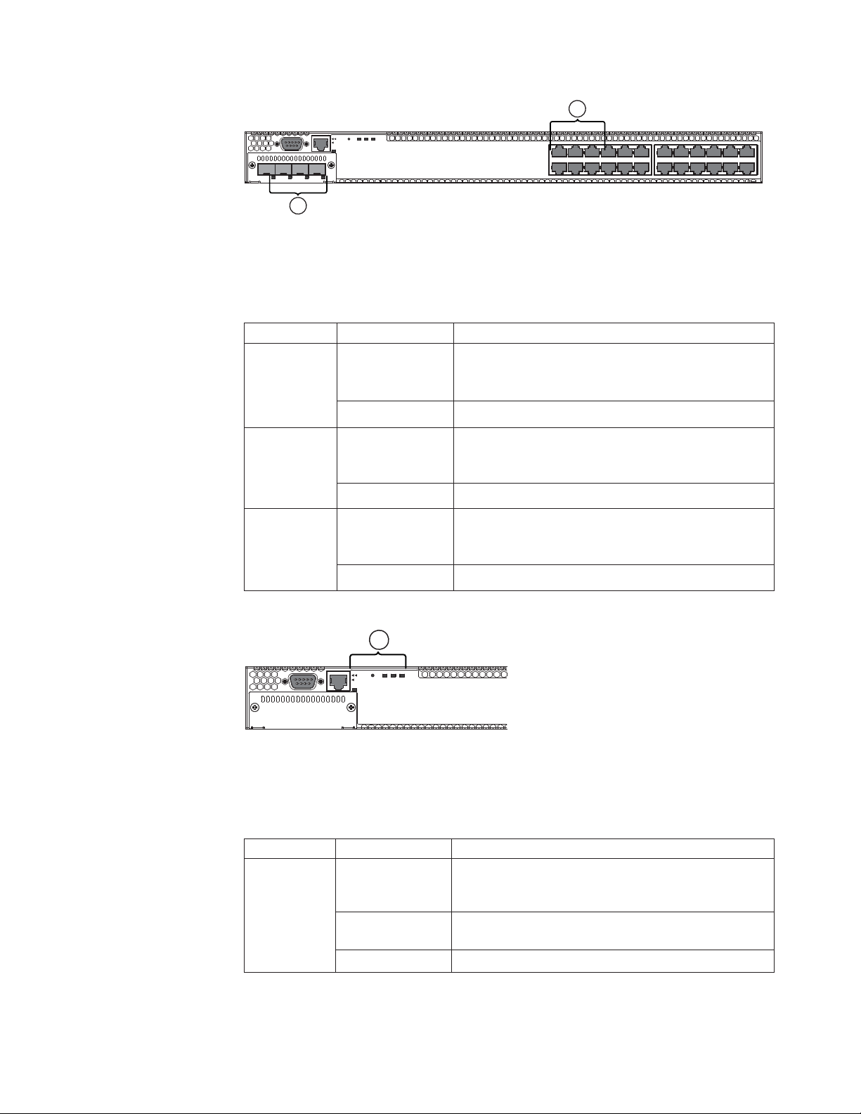
Chapter 1. Product overview
This guide describes the IBM y-series of Ethernet switches and includes procedures
for installing the hardware, and configuring essential basic parameters such as
permanent passwords and IP addresses. This guide also includes instructions for
managing and maintaining the hardware. The term y-series is used to distinguish
these Ethernet/IP switch models from other IBM Ethernet and IP router and switch
products. Through the remainder of this publication, these products will be
referred to generally as switches, by individual model names when necessary, and
as y-series switches when needed to distinguish from other switch product series.
IBM y-series of Ethernet switches
IBM y-series of Ethernet switches provide high 10/100/1000 Mbps port density
and available 10 Gbps Ethernet uplinks in a compact form factor. All y-series
models support Layer 2 and Enterprise Layer 3 protocols. Enterprise Layer 3
includes support for IPv4 unicast RIP and OSPF and IPv4 multicast PIM.
This section describes the physical characteristics of the IBM y-series of Ethernet
switches. For more details about physical dimensions, power supply specifications,
and pinouts, refer to Chapter 5, “Hardware specifications,” on page 49.
Note: Not all y-series models are available in all markets.
The IBM y-series of Ethernet switches includes the following models:
v The 4002-Y2A has twenty-four 10/100/1000 MbE RJ45 ports. The front panel has
one module slot for an optional 4-port 10/100/1000 MbE SFP module that
operates as combination (Combo) ports or a 4-port 10 GbE SFP+ module. Two
rear power supply receptacles allow for up to two 210 W power supply units
("-E" versions). These switches support port to non-port side (front to back)
airflow.
v The 4002-Y4A) has forty-eight 10/100/1000 MbE RJ45 ports. The front panel has
one module slot for an optional 4-port 10/100/1000 MbE SFP module that
operates as combination (Combo) ports or a 4-port 10 GbE SFP+ module. Two
rear power supply receptacles allow for up to two 210 W power supply units
("-E" versions). These switches support port to non-port side (front to back)
airflow.
v The 4002-Y2B) has twenty 10/100/1000 MbE RJ45 ports plus four combination
(Combo) ports which include four 10/100/1000 MbE RJ45 ports and four
100/1000 MbE SFP ports. The RJ45 ports support Power over Ethernet Plus
(PoE+). Two dedicated 16 Gbps CX4 ports on the rear panel allow stacking for
up to eight units. The front panel also has one module slot for an optional 2-port
10 GbE XFP module. Two rear power supply receptacles allow for up to two 620
W power supply units. Airflow is from the left side to right side (when facing
the port side of the switch).
v The 4002-Y4B has forty-four 10/100/1000 MbE RJ45 ports plus four combination
(Combo) ports which include four 10/100/1000 MbE RJ45 ports and four
100/1000 MbE SFP ports. The RJ45 ports support Power over Ethernet Plus
(PoE+). Two dedicated 16 Gbps CX4 ports on the rear panel allow stacking for
up to eight units. The front panel also has one module slot for an optional 2-port
© Copyright IBM Corp. 2010 1
Page 28
10 GbE XFP module. Two rear power supply receptacles allow for up to two 620
W power supply units. Airflow is from the left side to right side (when facing
the port side of the switch).
v The 4002-Y2C has twenty-four 10/100/1000 MbE RJ45 ports. The front panel has
one module slot for an optional 4-port 10/100/1000 MbE SFP module that
operates as combination (Combo) ports or a 4-port 10 GbE SFP+ module. Two
rear power supply receptacles allow for up to two 210 W power supply units
("-I" versions). These switches support non-port to port side (back to front)
airflow.
v The 4002-Y4C) has forty-eight 10/100/1000 MbE RJ45 ports. The front panel has
one module slot for an optional 4-port 10/100/1000 MbE SFP module that
operates as combination (Combo) ports or a 4-port 10 GbE SFP+ module. Two
rear power supply receptacles allow for up to two 210 W power supply units
("-I" versions). These switches support non-port to port side (back to front)
airflow.
All devices contain two management interfaces: a DB9 serial port (Console) and a
10/100/1000 MbE RJ45 (Out-of-band) management port.
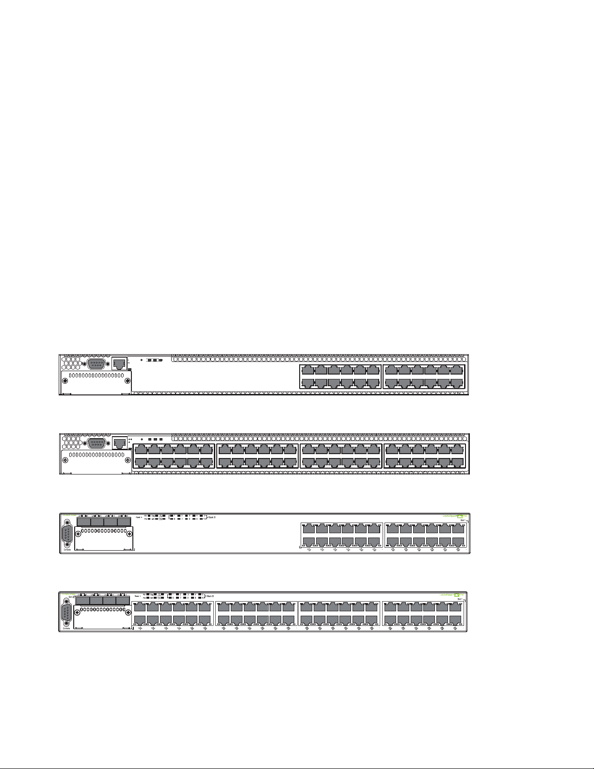
The following figures show the front and rear panels of the y-series models. For
more information about Combo ports, see “Combination ports” on page 4. For
more information about control features in general, see “Control features” on page
3.
Mgmt
Reset
Diag
PS 1 2
Console
Figure 1. 4002-Y2A and Y2C front panel
Reset
1PS2Diag
e
Consol
Mgmt
1357911 131517192123
2 4 6 8 10 12 14 16 18 20 22 24
Figure 2. 4002-Y4A and Y4C front panel
Slot3
Figure 3. 4002-Y2B front panel
1357911 131517192123
2 4 6 8 10 12 14 16 18 20 22 24
25 27 29 31 33 35 37 39 41 43 45 47
26 28 30 32 34 36 38 40 42
46 48
44
nety004
nety005
nety001
nety002
Figure 4. 4002-Y4B front panel
2 Ethernet y-series Installation and User Guide: Installation and User Guide
Page 29

Figure 5. 4002-Y2B and 4002-Y4B rear panel
Figure 6. 4002-Y2A, Y4A, and Y2C and Y4C rear panels
CAUTION:
For the 4002-Y2A, Y4A, Y2C, and Y4C devices, be sure that the airflow direction
of the power supply unit matches that of the installed resilient quad-fan tray.
The power supplies and fan trays for the Y2A and Y4A models are labeled with
an arrow with an “E”, power supplies and fan trays for the Y2C and Y4C models
are labeled with an arrow with an "I" as shown in Table 2.
Table 2. Power supply and fan tray labels for 4002-Y2A,Y4A, Y2C, and Y4C devices
Devices
4002-Y2A and 4002-Y4A 4002-Y2A and Y4A power
Label on required power
supply
supply airflow label
nety003
nety006
Label on required fan
tray
4002-Y2A and Y4A fan
tray airflow label
4002-Y2C and 4002-Y4C 4002-Y2C and Y4C power
Control features
Each device front panel includes the following control features:
v Serial management interface (the DB9 port labeled Console)
v Out-of-band 10/100/1000 MbE RJ45 management interface
ATTENTION
Power supply and
fan FRU airflow
E
AIRFLOW
supply airflow label
must be the
same to prevent
overheating.
ATTENTION
Power supply and
fan FRU airflow
must be the
same to prevent
AIRFLOW
overheating.
E
nety007
AIRFLOW
4002-Y2C and Y4C fan
tray airflow label
Nety040
AIRFLOW
nety008
nety039
Chapter 1. Product overview 3
Page 30

Serial management interface (DB9 Console port)
The serial management interface allows you to configure and manage the device
using a third-party terminal emulation application on a directly-connected PC. A
straight-through EIA or TIA DB9 serial cable ships with the device. The serial
management interface (DB9 Console port) is located on the left side of the front
panel.
Out-of-band 10/100/1000 MbE RJ45 management interface
The out-of-band 10/100/1000 MbE RJ45 management interface enables you to
configure and manage the device on an Ethernet management network. The device
can be managed using a variety of methods including the CLI via Telnet or SSH,
using the web-based GUI via HTTP/HTTPS, and 3rd party SNMP applications
such as IBM Systems Director.
Note: This port interfaces with the CPU only and not the data plane.
Network interfaces for 4002-Y2B and 4002-Y4B
The 4002-Y2B and 4002-Y4B models contain the following interfaces:
v 10/100/1000 MbE ports with RJ45 copper connectors
v 100/1000 MbE ports with mini-GBIC slots for MSA-compliant SFP transceivers
v Optional 2-port 10 GbE XFP module
v 16/10 Gbps CX4 ports
Network interfaces for 4002-Y2A, Y4A, Y2C, and Y4C
The 4002-Y2A ,Y4A, Y2C, and Y4C models contain the following interfaces:
v 10/100/1000 ports with RJ45 copper connectors
v 100/1000 ports with mini-GBIC slots for MSA-compliant SFP transceivers
v Optional 4-port 100/1000 MbE SFP module
v Optional 4-port 10 GbE SFP+ module
IBM y-series 10/100/1000 BASE-T ports: The RJ45 ports operate at 10 Mbps or
100 Mbps, half or full duplex, or at 1000 Mbps, full duplex. Because all ports
support automatic MDI or MDI-X operation, you can use straight-through cables
for all network connections to PCs or servers, or to other switches or hubs. In
addition, it is ideal and preferred to use straight-through cable for switch-to-switch
connections.
Each of these ports supports auto-negotiation, so the optimum transmission mode
(half or full duplex), and the data rate (10, 100, or 1000 Mbps) can be selected
automatically. If a device connected to one of these ports does not support
auto-negotiation, the communication mode of the port can be configured manually.
Combination ports: The y-series devices can contain four combination ports,
which are four Small Form Factor Pluggable (SFP) network interfaces (1F~4F) that
are shared with four of the RJ45 ports (ports 1~4). In the default configuration, if
an SFP transceiver is installed in a slot and has a valid link on its port, the
associated RJ45 port is disabled and cannot be used. The switch can also be
configured to force the use of a combination RJ45 port or SFP slot, as required.
Note: The 4002-Y2A, Y4A, Y2C, and Y4C devices do not ship with SFP ports. You
can install an optional 4-port 10/100/1000 MbE SFP module which operate
as combination ports, or an optional 4-port 10 GbE SFP+ module which
4 Ethernet y-series Installation and User Guide: Installation and User Guide
Page 31

operates as uplinks to support optical connectivity.
The 4002-Y2B and 4002-Y4B models contain four combination ports on the
base device.
Slot designations: Table 3 lists the slot designations for y-series models.
Table 3. Stack unit slots for y-series devices
Device Slot 1 Slot 2 Slot 3
4002-Y2A and
4002-Y2C
4002-Y4A and
4002-Y4C
4002-Y2B Twenty-four 10/100/1000
4002-Y4B devices
with optional
four-port 10 Gbps
SFP+ module
Twenty-four 10/100/1000
MbE RJ45 ports. Also the
ports on the optional 4-port
100/1000 MbE SFP module
which act as Combo ports
with the first four 10/100/100
MbE RJ45 ports.
Forty-eight 10/100/1000 MbE
RJ45 ports. Also the ports on
the optional 4-port 100/1000
MbE SFP module which act
as Combo ports with the first
four 10/100/100 MbE RJ45
ports.
MbE RJ45 ports plus the four
100/1000 MbE SFP ports
which act as Combo ports
with the first four 10/100/100
MbE RJ45 ports.
Forty-eight 10/100/1000 MbE
RJ45 ports plus the four
100/1000 MbE SFP ports
which act as Combo ports
with the first four 10/100/100
MbE RJ45 ports.
(Optional) Ports on the 4-port
10 GbE SFP+ module
(Optional) Ports on the 4-port
10 GbE SFP+ module
Two 16/10 Gbps CX4 ports on
rear panel
Two 16/10 Gbps CX4 ports on
rear panel
N/A
N/A
(Optional) Ports on the 2-port
10 GbE XFP module
(Optional) Ports on the 2-port
10 GbE XFP module
SFP interfaces
Table 4 describes the network interfaces on y-series devices.
Table 4. SFP network interfaces
Interface Show Media Description
1000Base-BX-D M-GBXD
1000Base-BX-U M-GBXU
1000Base-LHA M-LHA
1000Base-LHB M-LHB
1000Base-LX M-LX
1000Base-LH M-LH
1000Base-SX M-SX
1000Base-SX2 M-SX2
1000Base-T C
100Base-T C**
10Base-T C**
100Base-BX M-FBX
Chapter 1. Product overview 5
Page 32
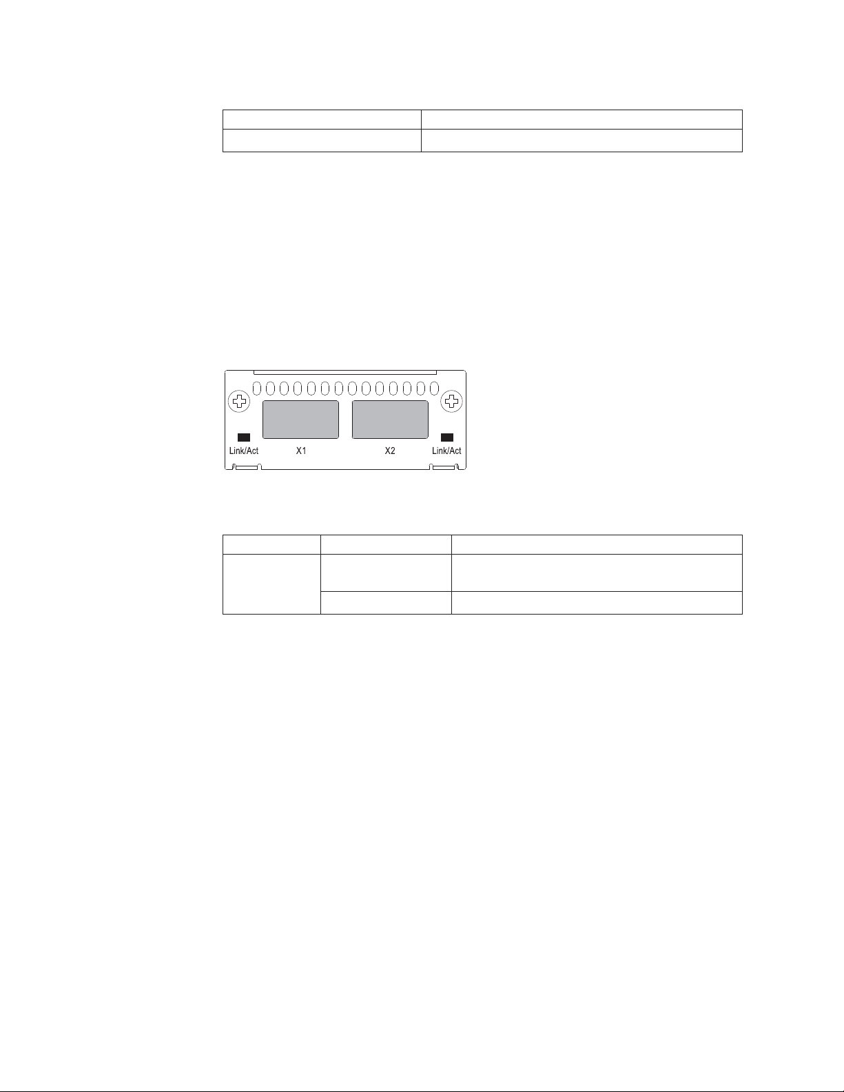
Table 4. SFP network interfaces (continued)
Interface Show Media Description
100Base-FX M-FX
Optional two-port 10 Gbps XFP uplink module
The 4002-Y2B and 4002-Y4B devices include a slot on the front panel for a two-port
10 Gbps XFP uplink module. This module operates at 10 Gbps full duplex.
The two 10 Gbps ports on this module can also be configured to support stacking
using the interface level CLI command, default-port. See the FastIron Configuration
Guide for additional information.
Note: The two-port 10 Gbps XFP uplink module is hot-swappable but requires a
reload for the ports to be discovered.
nety011
Figure 7. Two-port 10 Gbps XFP module
Table 5. 10 Gbps XFP module port status LEDs
LED Condition Status
Link or Act
LED (Link or
Activity)
On or flashing Green Port has a valid link at 10 Gbps. Flashing
indicates activity.
Off The link is down.
Optional four-port 100/1000 Mbps SFP and 10 Gbps SFP+ modules
The 4002-Y2A Y4A, Y2C, and Y4C devices include a slot on the front panel for a
four-port 100/1000 Mbps SFP module, or a four-port 10 Gbps SFP+ module. The
100/1000 Mbps SFP module operates at 100 Mbps full duplex and 1000 Mbps full
duplex, and the 10 Gbps SFP+ module operates at 10 Gbps full duplex.
These devices can be used in a y-series stack by installing the optional 10 Gbps
SFP+ module, and connecting devices using standard fiber cables. These devices
cannot be combined in a stack with non-y-series devices. For detailed information
about how to configure y-series devices in an IronStack topology, see the FastIron
Configuration Guide.
Note: The four-port 1 Gbps SFP and 10 Gbps SFP+ modules are not
hot-swappable.
6 Ethernet y-series Installation and User Guide: Installation and User Guide
Page 33
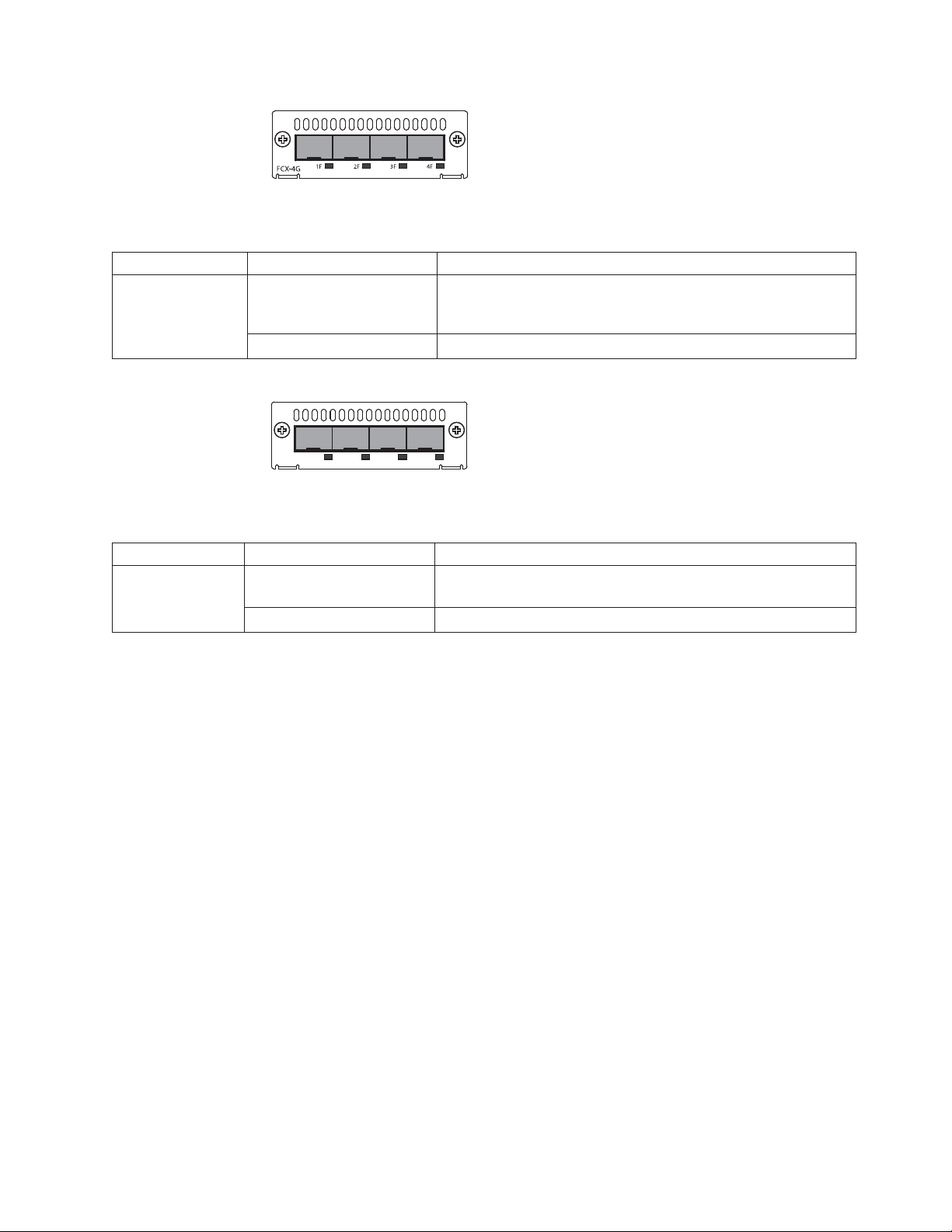
Figure 8. Four-port 1 Gbps SFP module
Table 6. Four-port 1 Gbps SFP module status LEDs
LED Condition Status
Link or Act LED
(Link or Activity)
Table 7. Four-port 10 Gbps SFP+ module status LEDs
LED Condition Status
Link or Act LED
(Link or Activity)
On or flashing Green The SFP port has established a valid 100/1000 Mbps link.
Flashing indicates the port is transmitting and receiving user
packets.
Off A link is not established with a remote port.
X1 X2 X3 X4
FCX-4XG
Figure 9. Four-port 10 Gbps SFP+ module
On or flashing Green The SFP+ port has established a valid 10 Gbps link. Flashing
indicates the port is transmitting and receiving user packets.
Off A link is not established with a remote port.
nety012
nety013
Note: The two left ports (ports <stack id>/2/1 and <stack id>/2/2) on the
four-port 10 Gbps SFP+ module do not pass regular Ethernet traffic by
default. If you want all four ports on the four-port 10 Gbps SFP+ module to
pass regular traffic, the global CLI command, stack disable, must be
configured on the device to disable stacking. For more information, see the
FastIron Configuration Guide.
16/10 Gbps Ethernet CX4 stacking ports
The 4002-Y2B and 4002-Y4B devices include two 16/10 Gbps Ethernet CX4 ports
on the rear panel. The device can perform data transmission directly through
copper links of up to 3 meters.
These CX4 ports are configured by default as 16 Gbps stacking ports which can
connect to other 4002-Y2B and 4002-Y4B devices in a stack of up to eight members.
Stacking simplifies deployment, management, and allows for data traffic to
traverse over these high-speed stack links. The CX4 ports can also be configured to
operate as 10 Gbps Ethernet ports by either disabling stacking on the device (stack
disable) or configuring other ports to be the default stack ports (default-ports),
and then setting the speed-duplex settings to 10 Gbps (speed-duplex). See the
FastIron Configuration Guide for additional details on stacking and configuration.
The Up Link and Down Link LEDs on the front panel indicate operational status.
If the Up Link or Down Link LED is on, the port is connected. If the Up Link or
Down Link LED is off, no connection exists, or the link is down.
Chapter 1. Product overview 7
Page 34
Cable specifications for CX4 stacking ports: The following cable specifications
apply to the CX4 stacking ports:
v Support for 802.3ak or 10 Gbps Ethernet CX4 standard and 16 Gbps inter-unit
stacking (up to 8 units in a stack)
v Support for cables up to 3 meters in length
v Requires latch-style receptacle or SFF-8470 plug
Note: 4002-Y2A and 4002-Y4A devices can inter-operate in a stack with the
4002-Y2B and 4002-Y4B devices by installing and configuring the optional 10
GbE modules on each device. See “Connecting devices in a stack” on page
19 and the FastIron Configuration Guide for additional information.
Port, system, and power status LEDs for the 4002-Y2B and 4002-Y4B
The 4002-Y2B and 4002-Y4B switches include a display panel for key system and
port indicators that simplifies installation and network troubleshooting. The LEDs,
which are located on the front panel for easy viewing, are shown below and
described in the following tables.
1 21
Slot3
Figure 10. Port status LEDs
1 RJ45 port status LEDs 2 SFP port status LEDs
Table 8. Port status LEDs
LED Condition Status
Ethernet (1~24/48)
Link or Activity or
Speed
HPoE (1~24/48) On Green The port is providing HPoE power to a connected device.
SFP (1F~4F) Link or
Activity
SFP (1F~4F) Speed On Green The SFP port is operating at 1000 Mbps.
On/Flashing Green The port has established a valid link at 1000 Mbps. Flashing
indicates the port is transmitting and receiving user packets.
On/Flashing Amber The port has established a valid link at 10 or 100 Mbps. Flashing
indicates the port is transmitting and receiving user packets.
Off A link is not established with a remote port.
Off The port is not providing HPoE power.
On/Flashing Green The SFP port has established a valid link. Flashing indicates the
port is transmitting and receiving user packets.
Off A link is not established with a remote port.
On Amber The SFP port is operating at 100 Mbps.
Off A link is not established with a remote port.
nety014
8 Ethernet y-series Installation and User Guide: Installation and User Guide
Page 35
1
Slot3
Figure 11. System status LEDs
1 System status LEDs
Table 9. System status LEDs
LED Condition Status
Green Power supply is operating normally.
PS1
PS2
Amber Power supply fault.
nety015
(Power Supply
Off Power off or failure.
Status)
Diag
(Diagnostic)
Flashing Green System self-diagnostic test in progress.
Green System self-diagnostic test successfully completed.
Amber System self-diagnostic test has detected a fault.
(Blower, thermal or any interface fault.)
AorS
Green “A” green device is the active controller for the stack.
“S” green device is the standby controller for the
(Active or
Standby)
Flashing Green Flashing device is the active controller for the stack,
stack.
system is initializing.
Amber Device is operating as a stack member in the stack.
Flashing Amber System is in active controller arbitration or election
state.
Off System in standalone mode.
Up Link or
Green Uplink operating normally.
Down Link
(Stacking
uplink or
Off Uplink has failed or no link.
downlink port
status)
Stack ID (1-8) Green Indicates the device stack ID.
1
Figure 12. Power status LEDs
nety016
Chapter 1. Product overview 9
Page 36

1 Power status LEDs
Table 10. Power status LEDs
LED Condition Status
DC OK Green DC output ok
Red DC output fail
AC OK Green AC input ok
Off AC input fail
Note: Both “AC OK” and “DC OK” LEDs must be green for the device to function
normally.
Table 11. Switch status for two installed power supply units
HPoE Budget
State LED PSU1 PSU2
Four Green
PSU LEDs
Single Red `DC
OK' LED
Both `DC OK'
LEDs Red
One PSU with
both `AC OK'
`DC OK' LEDs
Off
`DC OK' LEDs
Red and Off
All `AC OK'
LEDs Off
AC OK Green Green Running Yes 820W
DC OK Green Green
AC OK Green Green Running No 410W
DC OK Green Red
AC OK Green Green Failure No None
DC OK Red Red
AC OK Green Off Running No 410W
DC OK Green Off
AC OK Green Off Failure No None
DC OK Red Off
AC OK Off Off Power Off
DC OK Off Off
Switch
Status Load Sharing
No None
or Failure
(HPoE models
only)
Note: When two 620W power supplies are installed in an PoE system that has no
load or light load on the PoE function, one of two power supplies may have
its "DC OK" LED light red. There is no fault in the power supply or the
system and the switch is functioning normally. The LED will turn to green
automatically once the load is increased over the minimum load
requirement. In configurations with a single power supply installed the "DC
OK" LED will light green in a no-load or light-load condition.
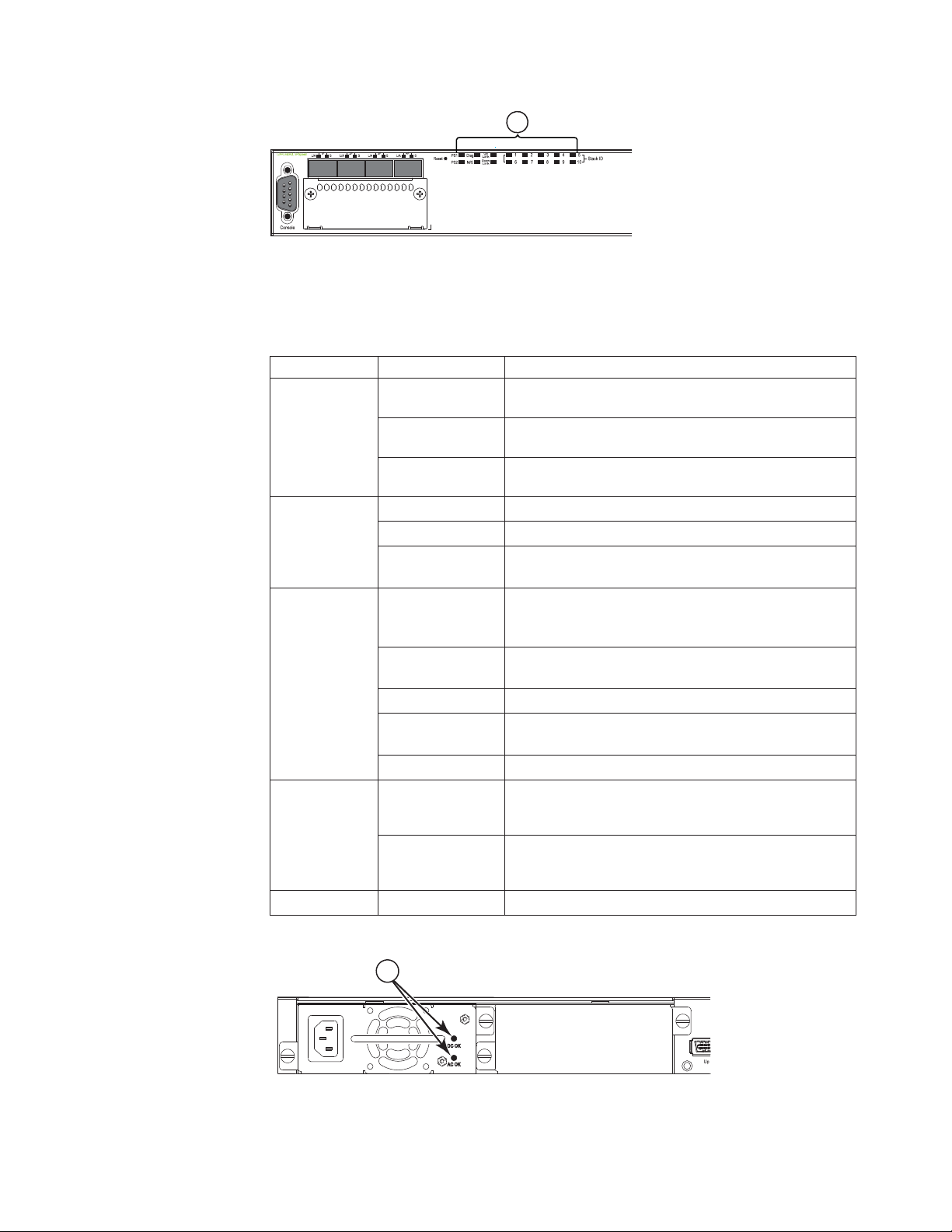
Port, system, and power status LEDs for the 4002-Y2A, Y4A, Y2C, and Y4C
The 4002-Y2A, Y4A, Y2C, and Y4C switches include a display panel for key system
and port indicators that simplifies installation and network troubleshooting. The
LEDs, which are located on the front panel for easy viewing, are shown below and
described in the following tables.
10 Ethernet y-series Installation and User Guide: Installation and User Guide
Page 37
1
Reset
1PS2 Diag
e
Consol
Mgmt
1357911 131517192123
2 4 6 8 10 12 14 16 18 20 22 24
2
Figure 13. Port status LEDs
1 RJ45 port status LEDs 2 SFP or SFP+ port status LEDs
Table 12. Port status LEDs
LED Condition Status
Ethernet
(1~24/48) Link
or
Activity or
Speed
SFP
(1F~4F)
On/Flashing
Green
The port has established a valid link at 10/100/1000
Mbps. Flashing indicates the port is transmitting and
receiving user packets.
Off A link is not established with a remote port.
On/Flashing
Green
The SFP port has established a valid 100/1000 Mbps
link. Flashing indicates the port is transmitting and
receiving user packets.
Link or
Activity
SFP+
(1F~4F)
Off A link is not established with a remote port.
On/Flashing
Green
The SFP+ port has established a valid 10 Gbps link.
Flashing indicates the port is transmitting and
receiving user packets.
Link or
Activity
Off A link is not established with a remote port.
nety017
1
1PS2Diag
Reset
Console
Mgmt
Figure 14. System status LEDs
1 System status LEDs
Table 13. System status LEDs
LED Condition Status
PS1
Green Power supply is operating normally. It is installed
properly and the power cord is attached to a power
PS2
(Power
Supply Status)
Amber Power supply fault. The power supply may not be
source.
installed properly.
Off Power off or failure.
nety018
Chapter 1. Product overview 11
Page 38
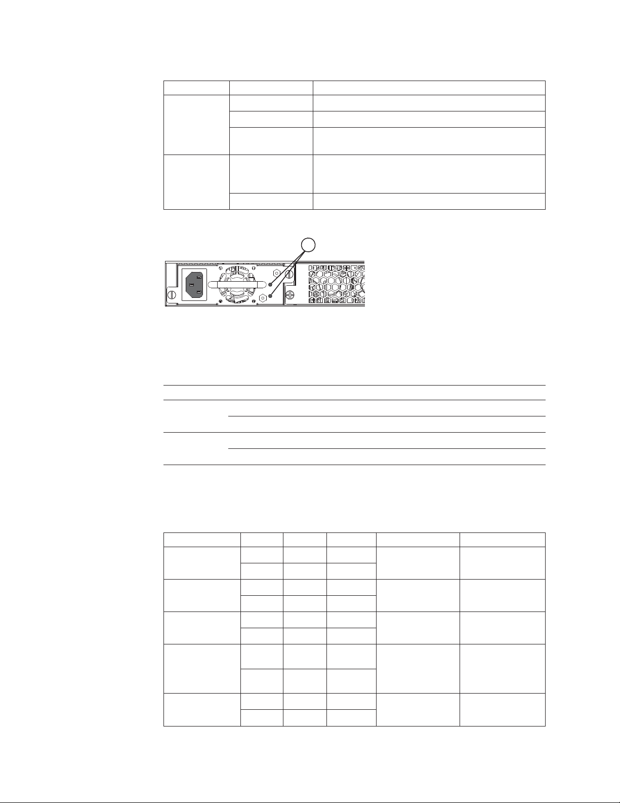
Table 13. System status LEDs (continued)
LED Condition Status
Diag
(Diagnostic)
Out-of-band
Management
Link or
Activity
Flashing Green System self-diagnostic test in progress.
Green System self-diagnostic test successfully completed.
Amber System self-diagnostic test has detected a fault.
(Blower, thermal or any interface fault.)
On/Flashing
Green
Off A link is not established with a remote port.
The port has established a valid link at 10/100/1000
Mbps. Flashing indicates the port is transmitting and
receiving user packets.
1
Figure 15. Power status LEDs
1 Power status LEDs
nety019
Table 14. Power status LEDs
LED Condition Status
DC OK Green DC output ok
Red DC output fail
AC OK Green AC input ok
Off AC input fail
Note: Both “AC OK” and “DC OK” LEDs must be green for the device to function
normally.
Table 15. Switch status for two installed power supply units
State LED PSU1 PSU2 Switch Status Redundancy
Four green PSU
LEDs
Single red `DC
OK' LED
Both `DC OK'
LEDs red
One PSU with
both `AC OK'
`DC OK' LEDs
off
`DC OK' LEDs
red and off
AC OK Green Green Running Yes
DC OK Green Green
AC OK Green Green Running No
DC OK Green Red
AC OK Green Green Failure No
DC OK Red Red
AC OK Green Off Running No
DC OK Green Off
AC OK Green Off Failure No
DC OK Red Off
12 Ethernet y-series Installation and User Guide: Installation and User Guide
Page 39
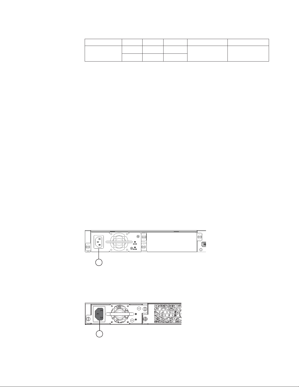
Table 15. Switch status for two installed power supply units (continued)
State LED PSU1 PSU2 Switch Status Redundancy
All `AC OK'
LEDs off
Power supplies
The y-series switches have two power receptacles on the rear panel. Each device
ships with one power supply unit (PSU) installed. The 4002-Y2A, Y4A, Y2C, and
Y4C devices use a 210W PSU. The 4002-Y2B and 4002-Y4B devices use a 620W
PSU.
Note: The 4002-Y2A and 4002-Y4A power supplies have an arrow with an "E" to
indicate airflow from port side to non-port side (front to back). The
4002-Y2C and 4002-Y4C power supplies have an arrow with an "I" to
indicate airflow from non-port side to port side (back to front). These power
supplies must be matched with fan trays that also have the same
corresponding "E" and "I" arrows on them (see Table 2 on page 3).
Each power supply has one standard (IEC-C14 inlet) power receptacle for the AC
power cable, and AC and DC status LEDs for easy monitoring and
troubleshooting.
AC OK Off Off Power off or
DC OK Off Off
failure
No
A secondary power supply can be installed to provide backup power in case of a
failure and for load-balancing when both power suppies are operational.
Load-balancing gives the power supplies a longer life span. Both 210W and 620W
PSUs are hot-swappable.
For instructions on installing and replacing a power supply refer to “Installing or
replacing a power supply unit” on page 23. For information on LED status refer to
Table 10 on page 10.
nety020
1
Figure 16. 4002-Y2B and 4002-Y4B AC power supply receptacle
1 AC power receptacle
nety021
1
Figure 17. 4002-Y2A, Y4A, Y2C, and Y4C AC power supply receptacle
Chapter 1. Product overview 13
Page 40

1 AC power receptacle
Power supply unit operation
When only one PSU is installed, both “AC OK” and “DC OK” LEDs on the
installed PSU must be green for the y-series device to function normally.
When two PSUs are installed, both “AC OK” and “DC OK” LEDs for one of the
installed PSUs must be green for the y-series device to function normally.
Power over Ethernet power supplies
The 4002-Y2B and 4002-Y4B devices use a 620W PSU. When one PSU is powering
the switch, the PoE budget is 410W. If both PSUs are installed and powering the
switch, each PSU provides 410W to the switch, increasing the PoE budget to 820W.
14 Ethernet y-series Installation and User Guide: Installation and User Guide
Page 41

Chapter 2. Installing a y-series switch
Installation precautions
Attention: The procedures in this manual are intended for qualified service
personnel.
Attention: Before beginning the installation, refer to the safety information in
“Safety notices” on page ix.
Unpacking the device
The y-series devices ship with all of the items listed below. Verify the contents of
your shipping container. If any items are missing, please contact your IBM
representative.
Package contents
The following items are included in your shipping carton:
v y-series device
v rack mount brackets
v warranty
v printed documentation and CD-ROM
v a straight-through EIA or TIA DB-9 serial cable (F/F). If you prefer to build your
own cable, see the pinout information in “Attaching a PC or terminal” on page
22
v four rubber feet
v 0.5 m CX4 cable (4002-Y2B and 4002-Y4B) devices only
General requirements
To manage the system, you need a management station, such as a PC running a
terminal emulation application. Connect the management station to the Console
serial port on the switch.
Use the serial connection to perform basic configuration tasks, including assigning
an IP address and network mask to the system. This information is required to
manage the system using the Web management interface, IronView Network
Manager, or using the CLI through Telnet.
Installation tasks
Follow the steps listed in Table 16 to install your device. Details for each of these
steps are provided on the pages indicated.
Table 16. Installation tasks
Task
Number Task Where to Find More Information
1 Ensure that the physical environment that will host the
device has the proper cabling and ventilation.
© Copyright IBM Corp. 2010 15
“Preparing the installation site” on page 16
Page 42

Table 16. Installation tasks (continued)
Task
Number Task Where to Find More Information
2 Install any required optional modules into the switch.
3 Install the device on a desktop or in an equipment rack. “Installing the device” on page 17
4 Once the device is physically installed, plug the device
into a nearby power source that adheres to the
regulatory requirements outlined in this manual.
5 Attach a terminal or PC to the y-series device. This will
enable you to configure the device through the
Command Line Interface (CLI).
6 No default password is assigned to the CLI. For
additional access security, assign a password.
7 Before attaching equipment to the device, you need to
configure an interface IP address to the subnet on
which it will be located. Initial IP address configuration
is performed using the CLI with a direct serial
connection. Subsequent IP address configuration can be
performed using the Web management interface.
8 Once you power on the device and assign IP addresses,
the system is ready to accept network equipment.
9 Test IP connectivity to other devices by pinging them
and tracing routes.
10 Continue configuring the device using the CLI or the
Web management interface. You also can use IronView
Network Manager to manage the device.
11 Secure access to the device. FastIron Configuration Guide
v “Installing an optional module on the
4002-Y2B and 4002-Y4B” on page 26
v “Installing an optional module on the
4002-Y2A, Y4A, Y2C, and Y4C” on page 27
“Powering on the system” on page 22
“Attaching a PC or terminal” on page 22
“Assigning permanent passwords” on page
29
“Configuring IP addresses” on page 30
“Connecting network devices” on page 34
“Testing connectivity” on page 38
FastIron Configuration Guide
Preparing the installation site
Cabling infrastructure
Ensure that the proper cabling is installed at the site. Refer to “Cable
specifications” on page 53 for a summary of supported cabling types and their
specifications.
Installation location
Before installing the device, plan its location and orientation relative to other
devices and equipment. Switches can be mounted in a standard 19-inch equipment
rack that meets EIA-310D standards, or on a flat surface. Be sure to follow the
guidelines below when choosing a location.
The site should meet the following requirements:
v Maintain temperatures within 0 to 40⁰ C (32 to 104⁰ F) and humidity levels
within 5% to 95%, non-condensing.
v Allow a minimum of 7.6 cm (3 in.) of space between the sides and the back of
the device and walls or other obstructions for proper air flow.
16 Ethernet y-series Installation and User Guide: Installation and User Guide
Page 43

v Allow at least 7.6 cm (3 in.) of space at the front and back of the device for the
twisted-pair, fiber-optic, and power cabling.
v Be accessible for installing, cabling, and maintaining the devices.
v Allow the status LEDs to be clearly visible.
v Allow for twisted-pair cable to be always routed away from power lines,
fluorescent lighting fixtures and other sources of electrical interference, such as
radios and transmitters.
v Allow for the unit to be connected to a separate grounded power outlet that
provides 100 to 240 VAC, 50 to 60 Hz, is within 2 m (6.6 feet) of each device and
is powered from an independent circuit breaker. As with any equipment, a filter
or surge suppressor is recommended.
Installing the device
You can install y-series devices on a desktop or in an equipment rack.
Desktop installation
Figure 18. Attaching the adhesive feet
1. Attach the four rubber adhesive feet to the bottom of the first switch.
2. Set the device on a flat desktop, table, or shelf near an AC power source. Make
sure that adequate ventilation is provided for the system. A 3 inch clearance is
recommended on each side.
3. If installing a single switch only, refer to “Powering on the system” on page 22.
4. If installing multiple switches, attach the adhesive feet to each one. Place each
device squarely on top of the one below, in any order.
Rack mount installation
Note: You need a #2 Phillips screwdriver for installation.
Before installing the switch in a rack, refer to “Rack installation” on page xvi for
important safety information.
Before mounting the switch in a rack, pay particular attention to the following
factors:
nety022
Chapter 2. Installing a y-series switch 17
Page 44

v Temperature: Since the temperature within a rack assembly may be higher than
the ambient room temperature, check that the rack-environment temperature is
within the specified operating temperature range. (Refer to “Displaying the
temperature” on page 43.)
v Mechanical loading: Do not place any equipment on top of a rack-mounted unit.
v Circuit overloading: Be sure that the supply circuit to the rack assembly is not
overloaded.
v Grounding: Rack-mounted equipment should be properly grounded. Particular
attention should be given to supply connections other than direct connections to
the mains.
Use the following steps to mount devices in rack.
1. Remove the rack mount kit from the shipping carton. The kit contains two
L-shaped mounting brackets and mounting screws.
2. Attach the mounting brackets to the sides of the device as illustrated in
Figure 19 and Figure 20.
Note: 4002-Y2A, Y4A, Y2C, and Y4C device brackets are mounted using three
screws, as shown in Figure 20.
Figure 19. Attaching the brackets for 4002-Y2B and 4002-Y4B
nety023
nety024
Figure 20. Attaching the brackets for 4002-Y2A, Y4A, Y2C, and Y4C
18 Ethernet y-series Installation and User Guide: Installation and User Guide
Page 45

3. Attach the device in the rack as illustrated in Figure 21.
nety025
Figure 21. Installing the device in a rack
4. If installing only a single switch, proceed to “Powering on the system” on page
22.
5. If installing multiple switches, mount them in the rack, one below the other, in
any order.
Connecting devices in a stack
4002-Y2B and 4002-Y4B devices
Figure 22 on page 20 shows how the stack cables are connected between switches
in a stack. The connection is based on 16/10 Gbps Ethernet, using CX4 cables.
y-series devices support linear and ring stack topologies and can also operate as
standalone devices.
In a linear stack topology there is a single stack cable connection between each
switch that carries two-way communications across the stack. In ring stack
topology, an extra cable is connected between the top and bottom switches forming
a "ring" or "closed-loop." The closed-loop cable provides a redundant path for the
stack link, so if one link fails, stack communications can be maintained. Figure 22
on page 20 illustrates a ring-topology stacking configuration.
You can form a stack containing up to eight y-series units. To connect switches in a
stack, do the following steps:
1. Plug one end of a stack cable into one of the CX4 stacking ports of the top unit.
2. Plug the other end of the stack cable into one of the stacking ports of the next
unit.
3. Repeat steps 1 and 2 for each unit in the stack. Form a simple chain starting
with a stacking port on the top unit and ending at a stacking port on the
bottom unit (stacking up to eight units).
4. To form a ring stack topology, plug one end of a stack cable into the remaining
stacking port on the bottom unit and the other end into the remaining stacking
port on the top unit.
Chapter 2. Installing a y-series switch 19
Page 46

Figure 22. Connecting switches in linear (top) and ring (bottom) topology stacks
5. One device in the stack will operate as the Active Controller, one will operate
as Standby Controller, with the rest of the units operating as stack members.
For information about how to configure your stack, see the FastIron
Configuration Guide.
4002-Y2A, Y4A, Y2C, and Y4C devices
Figure 23 on page 21 and Figure 24 on page 21 show how stacking cables are
connected between 4002-Y2A, Y4A, Y2C, and Y4C devices in a stack. The
connection is based on 10 Gbps SFP+ using LC-LC MM fiber cables. These devices
support linear and ring stack topologies with the optional SFP+ modules installed,
and can also operate in standalone mode.
Note: 4002-Y2A, Y4A, Y2C, and Y4C devices must have a 4-port 10 Gbps SFP+
module (optional) installed to operate in a stack.
You can form a stack containing up to 4002-Y2A, Y4A, Y2C, and Y4C units. The
first two ports on the 4-port 10 GbE SFP+ module are pre-configured to support
stacking.
Note: If you want to use all four ports on the four-port 10 Gbps SFP+ module to
pass regular traffic the global CLI command, stack disable, must be
configured on the device to disable stacking.
nety026
To connect switches in a stack, complete the following steps:
20 Ethernet y-series Installation and User Guide: Installation and User Guide
Page 47

1. Plug one end of an LC-LC MM fiber cable into one of the SFP+ stacking ports
of the top unit.
2. Plug the other end of the cable into one of the stacking ports of the next unit.
3. Repeat steps 1 and 2 for each unit in the stack. Form a simple chain starting
with a stacking port on the top unit and ending at a stacking port on the
bottom unit (stacking up to eight units). See Figure 23.
4. (Optional) To form a ring stack topology, plug one end of an LC-LC MM Fiber
cable into the remaining stacking port on the bottom unit and the other end
into the remaining stacking port on the top unit. See Figure 24.
Reset
1PS2 Diag
Console
Mgmt
1357911 131517192123
25 27 29 31 33 35 37 39 41 43 45 47
2 4 6 8 10 12 14 16 18 20 22 24
Reset
1PS2Diag
Console
Mgmt
Reset
1PS2Diag
Console
Mgmt
26 28 30 32 34 36 38 40 42
1357911 131517192123
2 4 6 8 10 12 14 16 18 20 22 24
1357911 131517192123
24681012 141618202224
46 48
44
Figure 23. Connecting 4002-Y2A, Y4A, Y2C, and Y4C devices in a linear stack topology
Reset
1PS2Diag
Console
Mgmt
1357911 131517192123
2 4 6 8 10 12 14 16 18 20 22 24
Reset
1PS2Diag
Console
Mgmt
Reset
1PS2Diag
Console
Mgmt
25 27 29 31 33 35 37 39 41 43 45 47
26 28 30 32 34 36 38 40 42
1357911 131517192123
2 4 6 8 10 12 14 16 18 20 22 24
1357911 131517192123
2 4 6 8 10 12 14 16 18 20 22 24
46 48
44
nety027
nety028
Figure 24. Connecting 4002-Y2A, Y4A, Y2C, and Y4C devices in a ring stack topology
The 4002-Y2A, Y4A, Y2C, and Y4C devices can also be stacked with the 4002-Y2B
and 4002-Y4B devices. This requires installing the optional 2-port 10 GbE XFP
module on the 4002-Y2B and 4002-Y4B. You will need to configure the ports on the
2-port 10 GbE XFP module to be stacking ports using the default-ports command.
See the FastIron Configuration Guide for additional information.
Chapter 2. Installing a y-series switch 21
Page 48
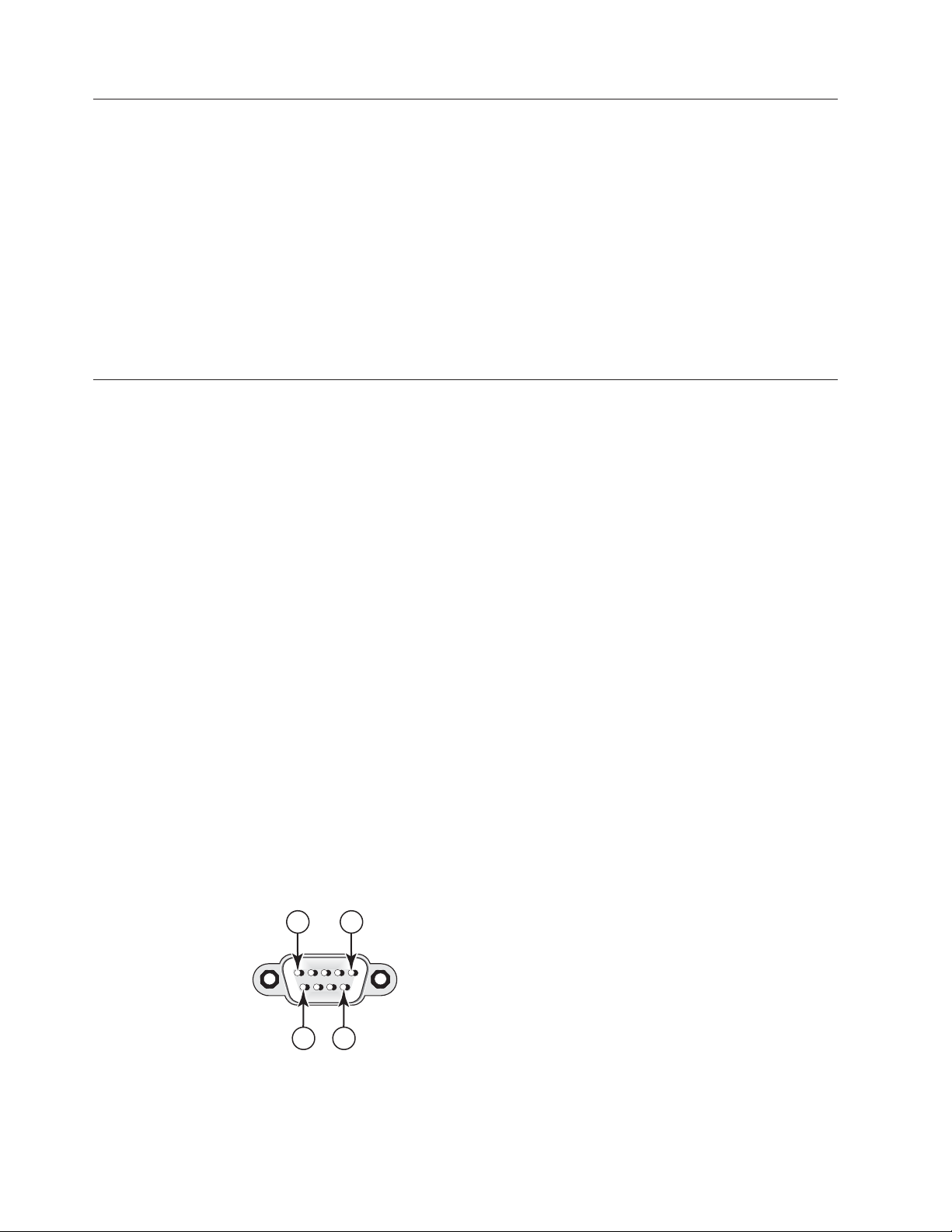
Powering on the system
After you have completed the physical installation, you can power on the system.
1. Remove the power cable from the shipping package.
2. Attach the AC power cable to the AC connector on the rear panel.
3. Insert the power cable plug into a 10A 120V or 240V outlet.
Notes:
1. To turn the system off, simply unplug the power cable or cables.
2. The socket should be installed near the equipment and should be easily
accessible.
3. If the outlet is not rated 10A 120V or 240V, stop and get the appropriate cable
for the outlet.
Attaching a PC or terminal
To assign an IP address, you must have access to the Command Line Interface
(CLI). The CLI is a text-based interface that can be accessed through a direct serial
connection to the device and through Telnet connections. The CLI is described in
detail in the FastIron Configuration Guide.
Access the CLI by attaching a serial cable to the Console port. After you assign an
IP address, you can access the system through Telnet, the Web management
interface, or IronView Network Manager.
Use the following steps to attach a management station to the serial port.
1. Connect a PC or terminal to the serial port of the system using a
straight-through cable. The serial port has a male DB-9 connector. See Figure 25.
2. On the PC, launch a terminal emulation program and set the following session
parameters:
v Baud: 9600 bps
v Data bits: 8
v Parity: None
v Stop bits: 1
v Flow control: None
The EIA or TIA 232 serial communication port serves as a connection point for
management by a PC or SNMP workstation. The y-series devices come with a
standard male DB-9 connector, shown in Figure 25.
15
6 9
net_com009
Figure 25. Serial port (DB-9 DTE) pin-out
22 Ethernet y-series Installation and User Guide: Installation and User Guide
Page 49
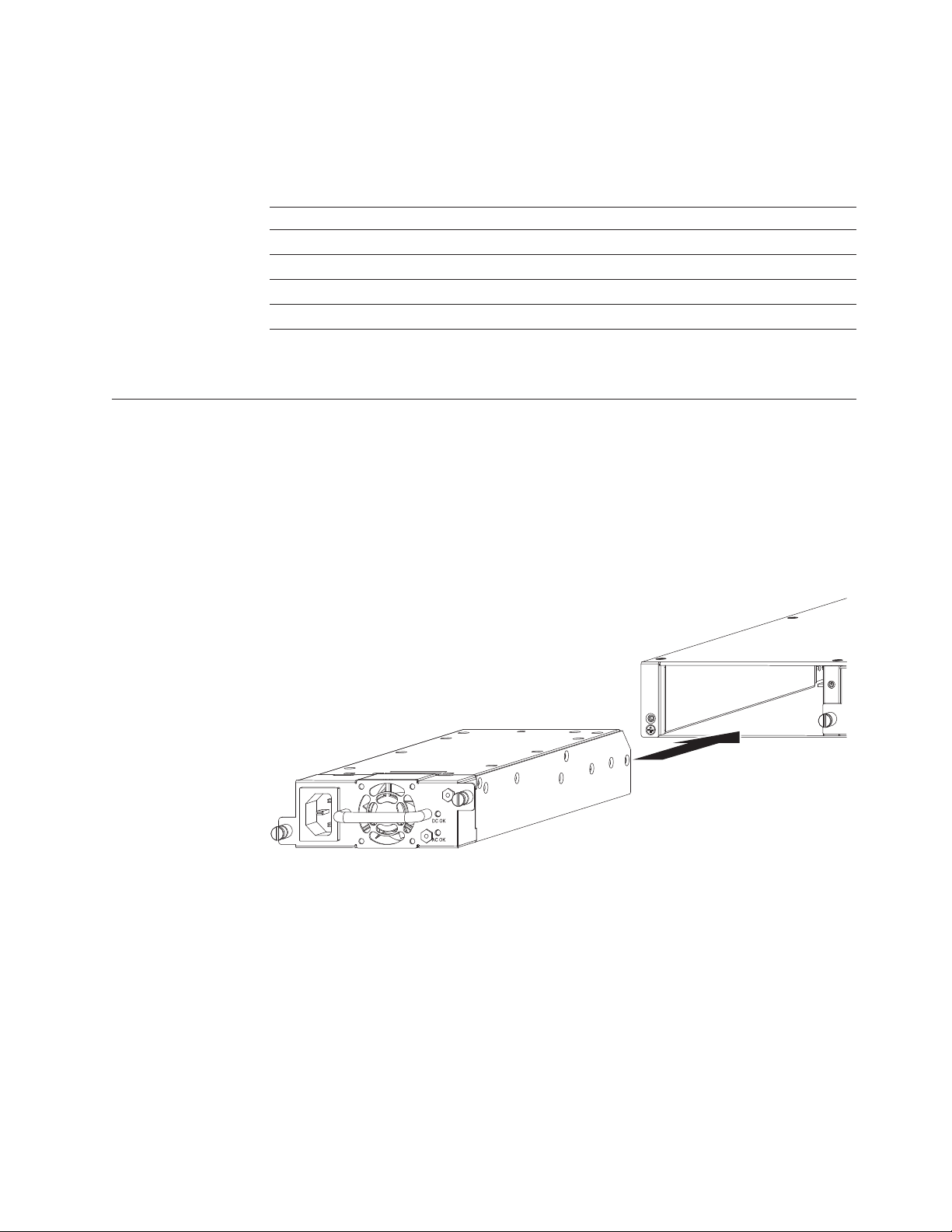
Most PC serial ports also require a cable with a female DB-9 connector. Terminal
connections will vary, requiring either a DB-9 or DB-25 connector, male or female.
Serial cable options between a y-series device and a PC or terminal are shown in
Table 17.
Table 17. Wiring map for serial cable
Switch 9-Pin Serial Port Null Modem PC 9-Pin DTE Port
2 TXD (transmit data) ——————————————> 2 RXD (receive data)
3 RXD (receive data) <—————————————— 3 TXD (transmit data)
5 SGND (signal ground) <—————————————> 5 SGND (signal ground)
No other pins are used.
Note: As indicated in Table 17 some of the wires should not be connected.
Installing or replacing a power supply unit
The power supplies are hot-swappable and can be replaced while the device is
powered on.
Attention: For the 4002-Y2A, Y4A, Y2C, and Y4C devices, be sure that the airflow
direction of the power supply unit matches that of the installed fan tray. The
power supplies and fan trays are clearly labeled with an arrow with an “E” or an
"I" as shown in Table 2 on page 3.
Figure 26. Installing a power supply unit
To install a power supply unit in the switch, do the following steps.
1. Remove the blank metal plate (or a previously installed PSU) from the
appropriate slot by removing the two screws with a flat-head screwdriver.
2. Before opening the package that contains the PSU, touch the bag to the switch
casing to discharge any potential static electricity. Using an ESD wrist strap
during installation is recommended.
3. Remove the PSU from the antistatic shielded bag.
4. Holding the PSU level, guide it into the carrier rails on each side and gently
push it all the way into the slot, ensuring that it firmly engages with the
connector.
5. When you are sure the PSU has properly engaged the connector, tighten the
retainer screws to secure the in PSU the slot.
Chapter 2. Installing a y-series switch 23
nety030
Page 50
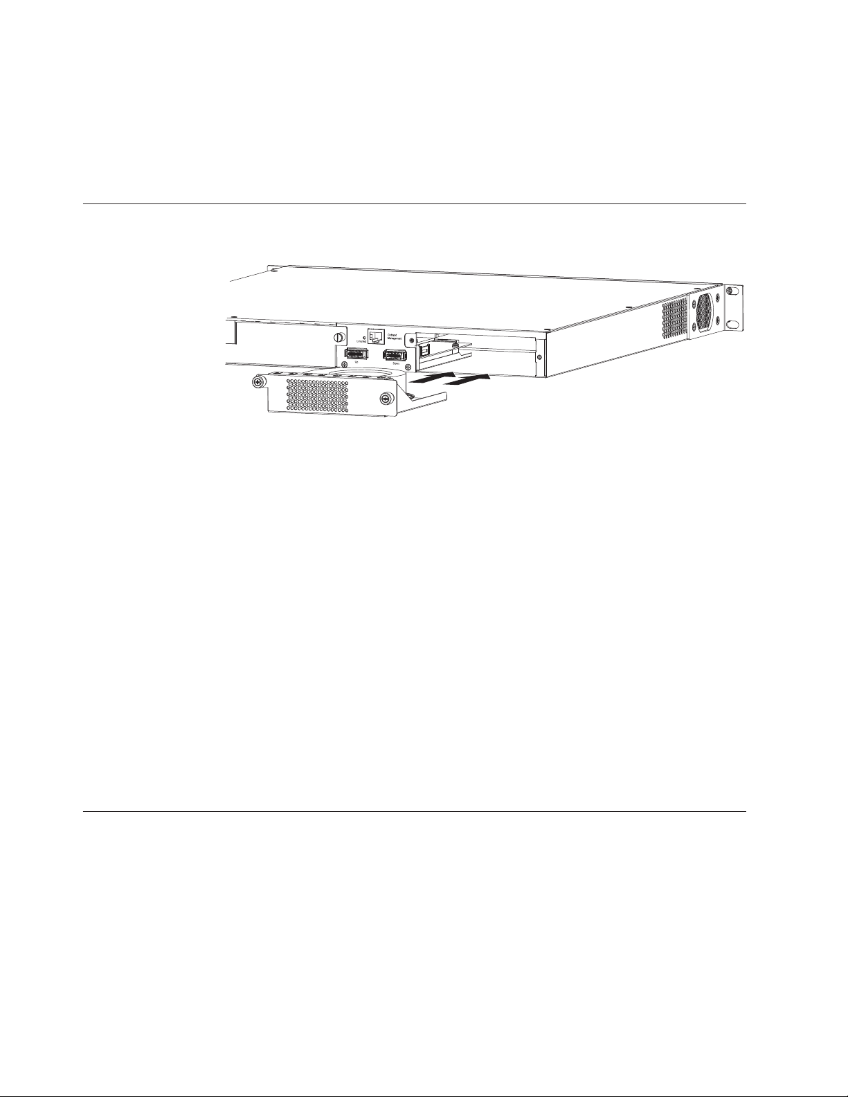
When the device is powered on, the PSU AC and DC LEDs on the PSU back panel
should turn green to confirm that the PSU is correctly installed and supplying
power.
Attention: If you do not install a PSU in a slot, you must keep the slot panel in
place. If you run the device with an uncovered slot, the system will overheat.
Installing and replacing a fan tray on the 4002-Y2B and 4002-Y4B
Figure 27. Installing a fan tray on the 4002-Y2B and 4002-Y4B
The fan tray is hot-swappable and can be replaced while the device is powered on.
If the device remains operational during fan tray replacement the procedure must
be completed within 30 seconds.
nety031
To install a fan tray in the switch, do the following steps.
1. Remove the previously installed fan tray from the slot by removing the two
screws with a crosshead or Philips #2 screwdriver.
2. Before opening the package that contains the new fan tray, touch the bag to the
switch casing to discharge any potential static electricity. Using an ESD wrist
strap during installation is recommended.
3. Remove the fan tray from the antistatic shielded bag.
4. Holding the fan tray level, guide it into the carrier rails on each side and gently
push it all the way into the slot, ensuring that it firmly engages with the
connector.
5. When you are sure the fan tray has properly engaged the connector, tighten the
retainer screws to secure the fan tray in the slot.
Note: The fans are controlled by software, and their speed is set according to the
environmental temperature surrounding the switch.
Installing and replacing a fan tray on the 4002-Y2A, Y4A, Y2C, and Y4C
Attention: For the 4002-Y2A, Y4A, Y2C, and Y4C devices, be sure that the airflow
direction of the power supply unit matches that of the installed fan tray. The
power supplies and fan trays are clearly labeled with an arrow with an “E” or an
"I", as shown in Table 2 on page 3.
24 Ethernet y-series Installation and User Guide: Installation and User Guide
Page 51
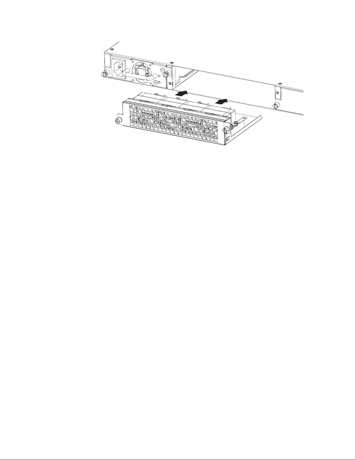
nety032
Figure 28. Installing a fan tray on the 4002-Y2A, Y4A, Y2C, and Y4C
The fan tray is hot-swappable and can be replaced while the device is powered on.
If the device remains operational during fan tray replacement the procedure must
be completed within 30 seconds.
Use the following procedure to install a fan tray in the switch.
1. Remove the previously installed fan tray from the slot by removing the two
screws with a crosshead or Philips #2 screwdriver.
2. Before opening the package that contains the new fan tray, touch the bag to the
switch casing to discharge any potential static electricity. Using an ESD wrist
strap during installation is recommended.
3. Remove the fan tray from the antistatic shielded bag.
4. Holding the fan tray level, guide it into the carrier rails on each side and gently
push it all the way into the slot, ensuring that it firmly engages with the
connector.
5. When you are sure the fan tray has properly engaged the connector, tighten the
retainer screws to secure the fan tray in the slot.
Note: The fans are controlled by software, and their speed is set according to the
environmental temperature surrounding the switch.
Chapter 2. Installing a y-series switch 25
Page 52
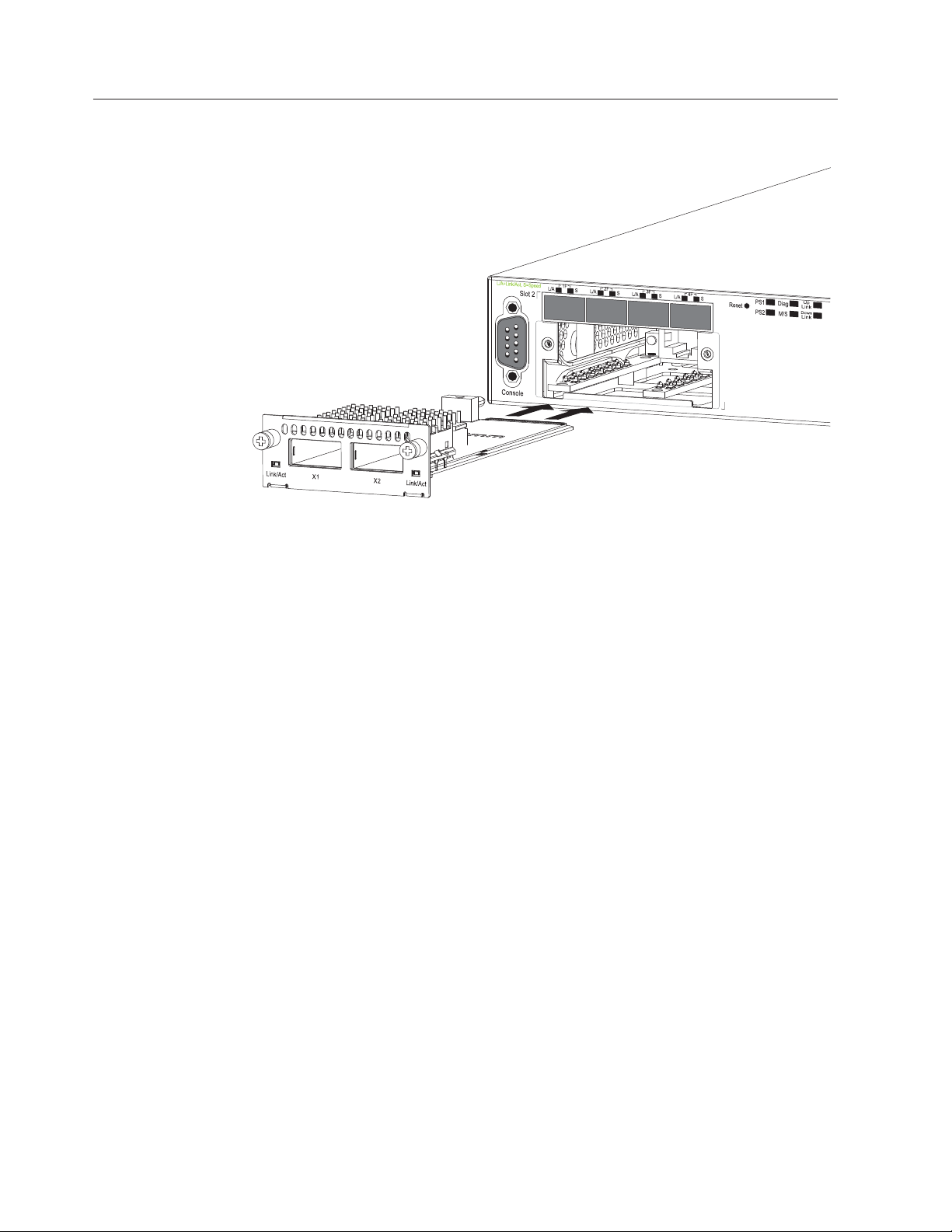
Installing an optional module on the 4002-Y2B and 4002-Y4B
Figure 29. Installing an optional module
The 4002-Y2B and 4002-Y4B switches support an optional two-port 10 Gbps
Ethernet XFP module. This module is hot-swappable / hot-installable, however a
reload command is required to recognize the new ports. It is recommended that
the device be powered off prior to installing this module.
nety034
Use the following procedure to install an optional module into the switch.
1. Power off the device by removing all power cords connected to the power
supplies.
2. Remove the blank metal plate (or a previously installed module) from the slot
by removing the two screws with a Phillips #2 screwdriver.
3. Before opening the package that contains the module, touch the bag to the
switch casing to discharge any potential static electricity. Using an ESD wrist
strap during installation is recommended.
4. Remove the module from the antistatic shielded bag.
5. Holding the module level, guide it into the carrier rails on each side and gently
push it all the way into the slot, ensuring that it firmly engages with the
connector.
6. When you are sure the module has properly engaged the connector, tighten the
retainer screws to secure the module in the slot.
7. Power on the switch by plugging in the power cords into the power supplies.
When the switch is powered on, the LEDs will follow the LED status as
described in “Port, system, and power status LEDs for the 4002-Y2B and
4002-Y4B” on page 8.
Attention: If you do not install a module in a slot, you must keep the slot panel
in place. If you run the device with an uncovered slot, the system will overheat.
26 Ethernet y-series Installation and User Guide: Installation and User Guide
Page 53
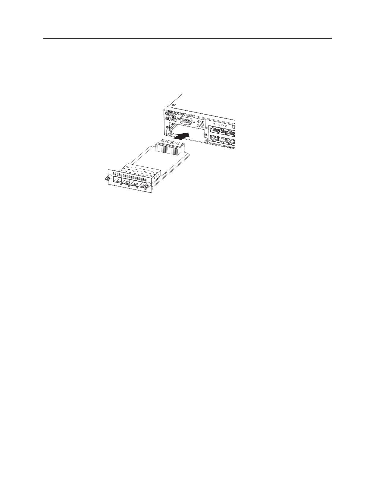
Installing an optional module on the 4002-Y2A, Y4A, Y2C, and Y4C
The 4002-Y2A, Y4A, Y2C, and Y4C switches support an optional four-port
100/1000 Mbps SFP module or four-port 10 Gbps SFP+ module. The 10 Gbps SFP+
module allows you to use your device in a stack. Figure 30 shows how to install an
optional SFP or SFP+ module.
nety034
Figure 30. Installing an optional module on the 4002-Y2A, Y4A, Y2C, and Y4C
Attention: The optional SFP and SFP+ modules are not hot-swappable. Be sure to
power-down your device before you install or replace a module.
Use the following procedure to install an optional module into the switch.
1. Remove the blank metal plate (or a previously installed module) from the slot
by removing the two screws with a Phillips #2 screwdriver.
2. Before opening the module package, touch the bag to the switch casing to
discharge any static electricity. Using an ESD wrist strap during installation is
recommended.
3. Remove the module from the antistatic shielded bag.
4. Hold the module level, guide it into the carrier rails and gently push it into the
slot until it firmly engages with the connector.
5. When the module is engaged, tighten the retainer screws to secure the module
in the slot.
6. Power on the switch by plugging in the power cords into the power supplies.
When the switch is powered on, the LEDs will follow the LED status as
described in “Port, system, and power status LEDs for the 4002-Y2A, Y4A, Y2C,
and Y4C” on page 10.
Note: The two left ports (ports <stack id>/2/1 and <stack id>/2/2) on the
four-port 10 Gbps SFP+ module do not pass regular Ethernet traffic by
default. If you want all four ports on the four-port 10 Gbps SFP+ module to
pass regular traffic the global CLI command, stack disable, must be
configured on the device to disable stacking. For more information, see the
FastIron Configuration Guide.
Attention: If you do not install a module in a slot, you must keep the slot panel
in place. If you run the device with an uncovered slot, the system will overheat.
Chapter 2. Installing a y-series switch 27
Page 54

28 Ethernet y-series Installation and User Guide: Installation and User Guide
Page 55

Chapter 3. Checking network devices and testing connectivity
The procedures in this chapter are for qualified system administrators and users.
Assigning permanent passwords
By default, the CLI is not protected by passwords. To secure CLI access, it is
strongly recommended that you assign passwords. See the FastIron Configuration
Guide.
Note: You cannot assign a password using the Web management interface. You can
assign passwords using IronView Network Manager if an enable password
for a Super User has been configured on the device.
The CLI contains the following access levels:
User EXEC
The level you enter when you first start a CLI session. At this level, you
can view some system information but you cannot configure system or
port parameters.
Privileged EXEC
This level is also called the Enable level and can be secured by a password.
You can perform tasks such as manage files on the flash module, save the
system configuration to flash, and clear caches at this level.
CONFIG
The configuration level. This level lets you configure the system IP address
and configure switching and routing features. To access the CONFIG
mode, you must already be logged into the Privileged level of the EXEC
mode.
You can set the following levels of Enable passwords:
Super User
Allows complete read-and-write access to the system. This is generally for
system administrators and is the only password level that allows you to
configure passwords.
Note: You must set a super user password before you can set other types
of passwords.
Port Configuration
Allows read-and-write access for specific ports but not for global
(system-wide) parameters.
Read Only
Allows access to the Privileged EXEC mode and CONFIG mode but only
with read access.
Setting passwords
1. At the opening CLI prompt, enter the following command to change to the
Privileged level of the EXEC mode:
FCX648SHPOE Switch> enable
2. Access the CONFIG level of the CLI by entering the following command:
© Copyright IBM Corp. 2010 29
Page 56

FCX648SHPOE Switch# configure terminal
FCX624 Router(config)#
3. Enter the following command to set the super user password:
FCX648SHPOE Switch(config)# enable super-user-password <text>
Note: You must set the super user password before you can set other types of
passwords.
4. Enter the following commands to set the port configuration and read-only
passwords:
FCX648SHPOE Switch(config)# enable port-config-password <text>
FCX648SHPOE Switch(config)# enable read-only-password <text>
Note: If you forget your super user password, refer to “Recovering from a lost
password.”
Syntax: enable super-user-password | read-only-password |
port-config-password <text>
Passwords can be up to 32 characters long.
Recovering from a lost password
By default, the CLI does not require passwords. However, if someone has
configured a password for the device but the password has been lost, you can
regain super user access to the device using the following procedure.
Note: Recovery from a lost password requires direct access to the serial port and a
system reset.
Use the following procedure to recover from a lost password.
1. Start a CLI session over the serial interface to the y-series device.
2. Reboot the device.
3. While the system is booting, before the initial system prompt appears, enter b
to enter the boot monitor mode.
4. Enter no password at the prompt. (You cannot abbreviate this command.)
5. Enter boot system flash primary at the prompt. This command causes the
device to bypass the system password check.
After the console prompt reappears, assign a new password.
Configuring IP addresses
You must configure at least one IP address using the serial connection to the CLI
before you can manage the system using the other management interfaces.
y-series devices support both classical IP network masks (Class A, B, and C subnet
masks, and so on) and Classless Interdomain Routing (CIDR) network prefix
masks.
v To enter a classical network mask, enter the mask in IP address format. For
example, enter
“209.157.22.99 255.255.255.0” for an IP address with a Class-C subnet mask.
v To enter a prefix number for a network mask, enter a forward slash(/)andthe
number of bits in the mask immediately after the IP address. For example, enter
“209.157.22.99/24” for an IP address that has a network mask with 24 significant
(“mask”) bits.
30 Ethernet y-series Installation and User Guide: Installation and User Guide
Page 57

By default, the CLI displays network masks in classical IP address format
(example: 255.255.255.0). You can change the display to the prefix format. See the
FastIron Configuration Guide.
Devices running Layer 2 software
Use the following procedure to configure an IP Address on a device running Layer
2 software.
1. At the opening CLI prompt, enter enable.
FCX648SHPOE Switch> enable
2. Access the configuration level of the CLI by entering the following command:
FCX648SHPOE Switch# configure terminal (Privileged EXEC Level)
FCX648SHPOE Switch(config)# (Global CONFIG Level)
3. Configure the IP address and mask for the switch.
FCX648SHPOE Switch(config)# ip address 192.22.3.44 255.255.255.0
4. Set a default gateway address for the switch.
FCX648SHPOE Switch(config)# ip default-gateway 192.22.3.1
Note: You do not need to assign a default gateway address for single subnet
networks.
Syntax: enable [<password>]
Syntax: configure terminal
Syntax: [no] ip address <ip-addr> <ip-mask>
or
Syntax: [no] ip address <ip-addr>/<mask-bits>
Syntax: ip default-gateway <ip-addr>
Devices running Layer 3 software
Before attaching equipment to a y-series Layer 3 Switch, you must assign an
interface IP address to the subnet on which the router will be located. You must
use the serial connection to assign the first IP address. For subsequent addresses,
you also can use the CLI through Telnet or the Web management interface.
By default, you can configure up to 24 IP interfaces on each port, virtual interface,
and loopback interface. You can increase this amount to up to 64 IP subnet
addresses per port by increasing the size of the subnet-per-interface table.
The following procedure shows how to add an IP address and mask to a router
port.
1. At the opening CLI prompt, enter enable.
FCX624 Router> enable
2. Access the configuration level of the CLI by entering the following command:
FCX624 Router# configure terminal Privileged EXEC Level
FCX624 Router(config)# Global CONFIG Level
3. Configure the IP addresses and mask addresses for the interfaces on the router.
FCX624 Router(config)# int e 2
FCX624 Router(config-if-e1000-2)# ip address 192.22.3.44 255.255.255.0
Note: You can use the syntax ip address <ip-addr>/<mask-bits> if you know the
subnet mask length. In the above example, you could enter ip address
192.22.3.44/24.
Chapter 3. Checking network devices and testing connectivity 31
Page 58

Syntax: enable [<password>]
Syntax: configure terminal
Syntax: [no] ip address <ip-addr> <ip-mask> [secondary]
or
Syntax: [no] ip address <ip-addr>/<mask-bits> [secondary]
Use the secondary parameter if you have already configured an IP address within
the same subnet on the interface.
Configuring IP parameters for devices running Layer 3 software
This section describes how to configure IP parameters for devices running Layer 3
software.
Configuring IP addresses: You can configure an IP address on the following
types of Layer 3 switch interfaces:
v Ethernet port
v Virtual routing interface (also called a Virtual Ethernet or “VE”)
v Loopback interface
By default, you can have up to 24 IP addresses on each interface except the
out-of-band management port, but you can increase this number to 128 IP
addresses.
Note: Once you configure a virtual routing interface on a VLAN, you cannot
configure Layer 3 interface parameters on individual ports in the VLAN.
Instead, you must configure the parameters on the virtual routing interface
itself.
y-series devices support both classical IP network masks (Class A, B, and C subnet
masks, and so on) and Classless Interdomain Routing (CIDR) network prefix
masks.
v To enter a classical network mask, enter the mask in IP address format. For
example, enter
“209.157.22.99 255.255.255.0” for an IP address with a Class-C subnet mask.
v To enter a prefix network mask, enter a forward slash(/)andthenumber of
bits in the mask immediately after the IP address. For example, enter
“209.157.22.99/24” for an IP address that has a network mask with 24 significant
bits (ones).
By default, the CLI displays network masks in classical IP address format (for
example: 255.255.255.0). You can change the display to prefix format.
Assigning an IP address to an Ethernet port: Enter the following commands to
assign an IP address to port 1/1/1.
FCX624 Router(config)# interface ethernet 1/1/1
FCX624 Router(config-if-1/1/1)# ip address 192.45.6.1 255.255.255.0
Note: You also can enter the IP address and mask in CIDR format, as follows:
FCX624 Router(config-if-1/1/1)# ip address 192.45.6.1/24
Syntax: [no] ip address <ip-addr> <ip-mask>
or
Syntax: [no] ip address <ip-addr>/<mask-bits>
32 Ethernet y-series Installation and User Guide: Installation and User Guide
Page 59

Assigning an IP address to a loopback interface: Loopback interfaces are always
up, regardless of the states of physical interfaces. They can add stability to the
network because they are not subject to route flap problems that can occur due to
unstable links between a Layer 3 Switch and other devices. You can configure up
to four loopback interfaces on a Layer 3 switch.
You can add up to 24 IP addresses to each loopback interface.
Note: If you configure the y-series switch to use a loopback interface to
communicate with a BGP4 neighbor, you must also configure a loopback
interface on the neighbor and configure the neighbor to use that loopback
interface to communicate with the y-series switch.
To add a loopback interface, enter commands such as those shown in the following
example:
FCX624 Router(config)# exit
FCX624 Router(config)# int loopback 1
FCX624 Router(config-lbif-1)# ip address 10.0.0.1/24
Syntax: interface loopback <num>
The <num> parameter specifies the virtual interface number. You can specify from
1 to the maximum number of virtual interfaces supported on the device. To display
the maximum number of virtual interfaces supported on the device, enter the
show default values command. The maximum is listed in the System Parameters
section, in the Current column of the virtual-interface row.
Assigning an IP address to a virtual routing interface: A virtual interface is a
logical port associated with a Layer 3 Virtual LAN (VLAN) configured on a Layer
3 switch. You can configure routing parameters on the virtual interface to enable
the Layer 3 switch to route protocol traffic from one Layer 3 VLAN to the other,
without using an external router.
This section describes how to configure an IP address on a virtual interface.
Note: The switch uses the lowest MAC address on the device (the MAC address of
port 1 or 1/1/1) as the MAC address for all ports within all virtual
interfaces you configure on the device.
Enter commands similar to the following to add a virtual interface to a VLAN and
configure an IP address on the interface.
FCX624 Router(config)# vlan 2 name IP-Subnet_1.1.2.1/24
FCX624 Router(config-vlan-2)# untag 1/1/1 to 1/1/4
FCX624 Router(config-vlan-2)# router-interface ve1
FCX624 Router(config-vlan-2)# interface ve1
FCX624 Router(config-vif-1)# ip address 1.1.2.1/24
The first two commands in this example create a Layer 3 protocol-based VLAN
name “IP-Subnet_1.1.2.1/24” and add a range of untagged ports to the VLAN. The
router-interface command creates virtual interface 1 as the routing interface for the
VLAN. The last two commands change to the interface configuration level for the
virtual interface and assign an IP address to the interface.
Syntax: router-interface ve <num>
Syntax: interface ve <num>
Deleting an IP address
Enter a command similar to the following to delete an IP address.
FCX624 Router(config-if-1/1/1)# no ip address 1.1.2.1
Chapter 3. Checking network devices and testing connectivity 33
Page 60

This command deletes IP address 1.1.2.1. You do not need to enter the subnet
mask.
To delete all IP addresses from an interface, enter the following command:
FCX624 Router(config-if-1/1/1)# no ip address *
Syntax: no ip address <ip-addr> | *
Connecting network devices
y-series devices support connections to other vendors' routers, switches, and hubs,
as well other IBM devices.
Connectors
For port pinouts, refer to “Pinouts and signaling” on page 52.
Cable specifications
Refer to “Cable specifications” on page 53 for cable lengths and types.
Connecting to Ethernet or fast Ethernet hubs
For copper connections to Ethernet hubs, a 10/100BaseTX or 1000BaseT switch, or
another device, a crossover cable is required. SeeFigure 31. If the hub is equipped
with an uplink port, it will require a straight-through cable instead of a crossover
cable. See Figure 32 on page 35.
Note: The 802.3ab standard (automatic MDI or MDIX detection) calls for automatic
negotiation of the connection between two 1000Base-T ports. In this case a
straight-through cable may work just as well as a crossover cable. For more
information about this feature, see the FastIron Configuration Guide.
10/100BASE-TX Crossover Cable
White/Orange Stripe
Orange
1
2
3
4
5
6
7
8
Figure 31. UTP crossover cable
White/Green Stripe
Blue
White/Blue Stripe
Green
White/Brown Stripe
Brown
1
2
3
4
5
6
7
8
End BEnd A
net_com010
34 Ethernet y-series Installation and User Guide: Installation and User Guide
Page 61

10/100BASE-TX Straight-through Cable
White/Orange Stripe
Orange
1
2
3
4
5
6
7
8
White/Green Stripe
Blue
White/Blue Stripe
Green
White/Brown Stripe
Brown
1
2
3
4
5
6
7
8
End BEnd A
Figure 32. Straight-through cable
Connecting to workstations, servers, or routers
Straight-through UTP cabling is required for direct UTP attachment to
workstations, servers, or routers using network interface cards (NICs).
Fiber cabling is required for direct attachment to Gigabit NICs or switches and
routers through fiber ports. Refer to “Connecting a network device to a fiber port.”
Automatic MDI or MDIX detection
All 10/100/1000 Mbps Ethernet Copper ports on the devices support automatic
Media Dependent Interface (MDI) and Media Dependent Interface Crossover
(MDIX) detection. This feature is enabled on all 10/100 and Gigabit copper ports
by default. For each port, you can disable auto MDI or MDIX, designate the port
as an MDI port, or designate the port as an MDIX port.
net_com011
For more information about this feature and how configure it, refer to FastIron
Configuration Guide.
Connecting a network device to a fiber port
For direct attachment from the device to a Gbps NIC, switch, or router, using a
fiber optic transceiver, you will need fiber cabling with an LC connector.
To connect the device to another network device using a fiber port, you must do
the following tasks:
v Install a fiber optic transceiver (XFP, SFP, or SFP+)
v Cable the fiber optic transceiver
The following sections describe these tasks.
Fiber Optic transceivers
Table 18 lists supported XFP transceivers (for stacking and non-stacking y-series
models). Table 19 on page 36 shows supported SFP and SFP+ transceivers. For
information about cabling for transceivers, see Table 28 on page 53.
Table 18. Supported XFP transceivers for 4002-Y2B and 4002-Y4B
10 Gigabit Optic Distance Supported for stacking
10GBase-SR 300M Yes
10GBase-LR 10km No
Chapter 3. Checking network devices and testing connectivity 35
Page 62

Table 18. Supported XFP transceivers for 4002-Y2B and 4002-Y4B (continued)
10 Gigabit Optic Distance Supported for stacking
10GBase-ER 40km No
Table 19. Supported SFP transceivers for 4002-Y2A, Y4A, Y2C, and Y4C
10 Gigabit Optic Distance Supported for stacking
10GSFPP-SR 300km Yes
10GSFPP-LR 10km No
Note: Distances supported on -SR optics depends on type of multi-mode fiber
cabling used. OM3, 50 micometer (2000 MHz*km) fiber is required to
support maximum distances.
Installing a transceiver
You can install a new transceiver in an XFP, SFP, or SFP+ slot while the device is
powered on and running.
While installing a transceiver, wear an ESD wrist strap with a plug for connection
to a metal surface.
Note: For safety reasons, the ESD wrist strap should contain a series 1 meg ohm
resistor.
CAUTION:
Data processing environments can contain equipment transmitting on
system links with laser modules that operate at greater than Class 1
power levels. For this reason, never look into the end of an optical fiber
cable or open receptacle. (C027)
Use the following steps to install a transceiver.
1. Put on the ESD wrist strap and ground yourself by attaching the clip end to a
metal surface (such as an equipment rack) to act as ground.
2. Remove the new transceiver from the protective packaging.
3. Gently insert the transceiver into the slot until it clicks into place. Transceivers
are keyed to prevent incorrect insertion.
36 Ethernet y-series Installation and User Guide: Installation and User Guide
Page 63

S
lo
t
3
nety035
Figure 33. Installing a transceiver in 4002-Y2B and 4002-Y4B devices
nety036
Figure 34. Installing a transceiver in 4002-Y2A, Y4A, Y2C, and Y4C devices
Cabling a fiber optic transceiver
Use the following steps to cable a fiber optic transceiver.
1. Remove the protective covering from the fiber-optic port connectors and store
the covering for future use.
2. Before cabling a fiber optic transceiver, it is strongly recommended that you
clean the cable connectors and the port connectors. For more information, refer
to “Cleaning the fiber optic connectors.”
3. Gently insert the cable connector (a tab on each connector should face upward)
into the transceiver connector until the tabs lock into place.
4. Observe the link and active LEDs to determine if the network connections are
functioning properly. For more information about the LED indicators, refer to
Table 20 on page 38.
Cleaning the fiber optic connectors
To avoid problems with the connection between the fiber optic transceiver (SFP,
SFP+, or mini-GBIC) and the fiber cable connectors, it is strongly recommended
that you clean both connectors each time you disconnect and reconnect them. Dust
can accumulate in the connectors and cause problems such as reducing the optic
launch power.
Chapter 3. Checking network devices and testing connectivity 37
Page 64

To clean the fiber cable connectors, it is recommended that you use a fiber optic
reel-type cleaner. You can purchase this type of cleaner from the following Web
site:
http://www.fisfiber.com/Home_Page.asp
When not using an SFP connector, make sure to keep the protective covering in
place.
Testing connectivity
Test for connectivity by observing the LEDs related to network connection.
Pinging an IP address
To verify that a y-series device can reach another device through the network,
enter a command similar to the following at any level of the CLI.
FCX648SHPOE Switch> ping 192.33.4.7
Syntax: ping <ip addr> [source <ip addr>] [count <num>] [timeout <msec>] [ttl <num>]
[verify] [no-fragment] [quiet] [data <1-to-4 byte hex#, e.g. abcdef00>] [numeric]
[size <byte>] [brief [max-print-per-sec <num 0-2047>]]
Note: If you address the ping to the IP broadcast address, the device lists the first
four responses.
Observing LEDs
After you install the network cables, you can observe certain LEDs to determine if
the network connections are functioning properly. Table 20 outlines the LEDs
related to the network connections, the desired state of each LED, possible
abnormal states of each LED, and what to do if an LED indicates an abnormal
state. For the locations of the LEDs, see “Control features” on page 3.
Table 20. Network connection-related LED states.
Desired
LED
Ethernet
(1-24/48)
Link or
Activity
or Speed
State Meaning
On or
Blinking
(Green or
Amber)
A link is established
with the remote port
and user packets are
being transmitted or
received.
Abnormal
State Meaning or Action
Off A link is not established with the remote port. You
can do the following:
v Verify that the connection to the other network
device has been properly made. Also, make certain
that the other network device is powered on and
operating correctly.
v Verify that the port has not been disabled through a
configuration change. You can use the CLI. If you
have configured an IP address on the device, you
also can use the Web management interface or
IronView Network Manager.
v For the combination ports (ports 1~4), check that
the shared SFP port (1F~4F) is not being used.
v If the other actions don't resolve the problem, try
using a different port or a different cable.
38 Ethernet y-series Installation and User Guide: Installation and User Guide
Page 65

Table 20. Network connection-related LED states. (continued)
LED
HPOE
Desired
State Meaning
On Green The port is providing
Abnormal
State Meaning or Action
Off A link is not established with the HPOE device. You
HPOE power.
(1-24/48)
SFP
(1F~4F)
On Green A link is established
with the remote port.
Off A link is not established with the remote port. You
Link or
Activity
SFP
(1F~4F)
On (Green
or Amber)
A link is established
with the remote port.
Off A link is not established with the remote port. You
Speed
can do the following:
v Verify that the connection to the other network
device has been properly made.
v If the other actions don't resolve the problem, try
using a different port or a different cable.
can do the following:
v Verify that the connection to the other network
device has been properly made. Also, make certain
that the other network device is powered on and
operating correctly.
v Verify that the transmit port on the y-series device
is connected to the receive port on the other
network device, and that the receive port on the
y-series device is connected to the transmit port on
the other network device. If you are not certain,
remove the two cable connectors from the port
connector and reinsert them in the port connector,
reversing their order.
v Dust may have accumulated in the cable connector
or port connector. For information about cleaning
the connectors, refer to “Cleaning the fiber optic
connectors” on page 37.
v Verify that the port has not been disabled through a
configuration change.
v Check that the configuration has not forced the use
of the RJ45 port shared with the SFP port.
v If the other actions don't resolve the problem, try
using a different port or a different cable.
can do the following:
v Check the Link LED to make sure the link is still
established with the remote port. If not, take the
actions described in the Meaning or Action column
for the Link LED.
Chapter 3. Checking network devices and testing connectivity 39
Page 66

Table 20. Network connection-related LED states. (continued)
LED
SFP+
(1F~4F)
Link or
Activity
SFP+
(1F~4F)
Speed
Desired
State Meaning
On Green A link is established
with the remote port.
On (Green
or Amber)
A link is established
with the remote port.
Abnormal
State Meaning or Action
Off A link is not established with the remote port. You
Off A link is not established with the remote port. You
can do the following:
v Verify that the connection to the other network
device has been properly made. Also, make certain
that the other network device is powered on and
operating correctly.
v Verify that the transmit port on the y-series device
is connected to the receive port on the other
network device, and that the receive port on the
y-series device is connected to the transmit port on
the other network device. If you are not certain,
remove the two cable connectors from the port
connector and reinsert them in the port connector,
reversing their order.
v Dust may have accumulated in the cable connector
or port connector. For information about cleaning
the connectors, refer to “Cleaning the fiber optic
connectors” on page 37.
v Verify that the port has not been disabled through a
configuration change.
v Check that the configuration has not forced the use
of the RJ45 port shared with the SFP port.
v If the other actions don't resolve the problem, try
using a different port or a different cable.
can do the following:
v Check the Link LED to make sure the link is still
established with the remote port. If not, take the
actions described in the Meaning or Action column
for the Link LED.
If a problem persists after taking these actions, contact IBM customer support.
Tracing a route
To determine the path through which a y-series device can reach another device,
enter a command similar to the following at any level of the CLI on the device.
FCX648SHPOE Switch> traceroute 192.33.4.7
Syntax: traceroute <host-ip-addr> [maxttl <value>] [minttl <value>] [numeric]
[timeout <value>] [source-ip <ip addr>]
The CLI displays trace route information for each hop as soon as the information is
received. Traceroute requests display all responses to a given TTL. In addition, if
there are multiple equal-cost routes to the destination, the y-series device displays
up to two responses by default.
Troubleshooting network connections
v For the indicated port, verify that both ends of the cabling (at the device and the
connected device) are snug.
40 Ethernet y-series Installation and User Guide: Installation and User Guide
Page 67

v Verify that the device and the connected device are both powered on and
operating correctly.
v Verify that you have used the correct cable type for the connection:
– For twisted-pair connections to an end node, use straight-through cabling.
– For fiber optic connections, verify that the transmit port on the device is
connected to the receive port on the connected device, and that the receive
port on the device is connected to the transmit port on the connected device.
v Use the CLI to verify that the port has not been disabled through a
configuration change. If you have configured an IP address on the device, you
also can use the Web management interface or IronView Network Manager.
v If the other procedures don't resolve the problem, try using a different port or a
different cable.
Using Virtual Cable Testing to diagnose a cable
These devices support Virtual Cable Test (VCT) technology. VCT technology
enables you to diagnose a conductor (wire or cable) by sending a pulsed signal
into the conductor, then examining the reflection of that pulse. This method of
cable analysis is referred to as Time Domain Reflectometry (TDR). By examining
the reflection, the device can detect and report cable statistics such as local and
remote link pair, cable length, and link status.
Configuration notes
v This feature is supported on copper ports only. It is not supported on fiber ports.
v The port to which the cable is connected must be enabled when you issue the
command to diagnose the cable. If the port is disabled, the command is rejected.
v If the port is operating at 100 Mbps half-duplex, the TDR test on one pair will
fail.
v If the remote pair is set to forced 100 Mbps, any change in MDI or MDIX may
cause the device to interpret the Multilevel Threshold-3 (MLT-3) as a reflected
pulse, in which case, the device will report a faulty condition. In this case, it is
recommended that you run the TDR test a few times for accurate results.
Command syntax
To diagnose a cable using TDR, enter a command such as the following at the
Privileged EXEC level of the CLI.
FCX648SHPOE Switch# phy cable-diag tdr 1/1/1
This command diagnoses the cable attached to port 1/1/1.
Syntax: phy cable-diag tdr <port-num>
Viewing the results of the cable analysis
To display the results of the cable analysis, enter a command similar to the
following at the Privileged EXEC level of the CLI.
FCX648SHPOE Switch# show cable-diag tdr 1/1/1
Syntax: show cable-diag tdr <port-num>
Table 21 defines the fields shown in cable statistics.
Table 21. Cable statistics
This Line... Displays...
Port The port that was tested.
Speed The current line speed of the port.
Chapter 3. Checking network devices and testing connectivity 41
Page 68

Table 21. Cable statistics (continued)
This Line... Displays...
Local pair The local link name.
Pair Length The cable length when terminated, or the distance to the point of fault
when the line is not up.
Remote pair The remote link name.
Pair status The status of the link. This field displays one of the following:
v Terminated: The link is up.
v Shorted: A short is detected in the cable.
v Open: An opening is detected in the cable.
v ImpedMis: The impedance is mismatched.
v Failed: The TDR test failed.
Digital optical monitoring
You can configure your device to monitor optical transceivers in the system, either
globally or by specified port. When this feature is enabled, the system monitors the
temperature and signal power levels for the optical transceivers in the specified
ports. Console messages and syslog messages are sent when optical operating
conditions fall below or rise above the XFP, SFP, and SFP+ manufacturer's
recommended thresholds. For more information about digital optical monitoring,
refer to FastIron Configuration Guide.
42 Ethernet y-series Installation and User Guide: Installation and User Guide
Page 69

Chapter 4. Managing y-series Ethernet switches
Attention: The procedures in this chapter are for qualified users and
administrators.
Managing temperature settings
This section describes how to display temperature settings on the device and how
to change the temperature warning and shutdown levels.
Using the temperature sensor
The device ships with three built-in temperature sensors that cause the device to
generate a Syslog message and SNMP trap if the temperature exceeds a specified
warning level or shutdown level. If the device temperature exceeds the safe
threshold (shutdown level), the device will reboot.
The software reads the temperature sensors based on the device poll time, which is
by default 60 seconds. If the temperature equals or exceeds the shutdown
temperature for five consecutive polls by the software, the software will reboot the
device to prevent damage.
You can use the CLI or Web management interface to perform the following tasks:
v Display the temperature of the device
v Change the warning and shutdown temperature levels
v Change the device poll time
Displaying the temperature
By default, the software polls the temperature sensor every 60 seconds to get the
current temperature. This poll rate is controlled by the device poll time, which also
controls how often the software polls other system components.
To display the temperature of a device, enter the show chassis command at any
level of the CLI.
FCX624S Switch# show chassis
The stack unit 1 chassis info:
Power supply 1 (NA - AC - Regular) present, status ok
Power supply 2 not present
Fan ok, speed (auto):