


Page 1

IBM x-series of Ethernet Switches
Installation and User Guide
Service information: 4002-X2A, 4002AX2
GC27-2267-00
Page 2

Page 3

IBM x-series of Ethernet Switches
Installation and User Guide
Service information: 4002-X2A, 4002AX2
GC27-2267-00
Page 4

Note:
Before using this information and the product it supports, be sure to read the general information in Appendix B, “Notices,” on
page 51.
The following paragraph does not apply to any country (or region) where such provisions are inconsistent with local
law.
INTERNATIONAL BUSINESS MACHINES CORPORATION PROVIDES THIS PUBLICATION ″AS IS″ WITHOUT
WARRANTY OF ANY KIND, EITHER EXPRESS OR IMPLIED, INCLUDING, BUT NOT LIMITED TO, THE IMPLIED
WARRANTIES OF MERCHANTABILITY OR FITNESS FOR A PARTICULAR PURPOSE. Some states (or regions) do
not allow disclaimer of express or implied warranties in certain transactions; therefore, this statement may not apply
to you.
Order publications through your IBM representative or the IBM branch office serving your locality.
© Copyright International Business Machines Corporation 2009.
US Government Users Restricted Rights – Use, duplication or disclosure restricted by GSA ADP Schedule Contract
with IBM Corp.
Page 5

Contents
Figures ...........................vii
Tables ............................ix
Preface ............................xi
Safety notices .........................xi
Safety notices and labels ....................xi
Notes ..........................xii
Attention notices ......................xii
Caution notices .......................xii
Danger notices .......................xiii
Safety labels .......................xvi
Rack safety.........................xviii
Rack installation ......................xviii
Rack relocation (19″ rack)...................xix
Product recycling and disposal ...................xix
Product documents .......................xx
Software documents .......................xx
Accessibility features for the IBM x-series of Ethernet Switches .......xxii
Accessibility features .....................xxii
Keyboard navigation .....................xxii
Vendor software .......................xxii
Related accessibility information .................xxii
IBM and accessibility .....................xxiii
Getting help .........................xxiii
Taiwan Contact Information ...................xxiii
How to send your comments ...................xxiii
About This Document ......................xxiii
Audience .........................xxiv
Supported hardware and software ................xxiv
Document conventions ....................xxiv
Text formatting ......................xxiv
Command syntax conventions .................xxiv
Chapter 1. Product Overview ...................1
Software features........................1
Hardware features ........................1
Control features .........................2
Serial management interface (Console port)..............2
Management port.......................2
Network interfaces ........................2
Viewing the media types installed in the ports .............3
10 Gbps ports.........................3
Four 10/100/1000 Mbps ports
10GbE SFP+ transceiver.....................4
LEDs for network interfaces and power supplies .............4
Power supplies .........................6
Chapter 2. Installing the B24X ...................9
Unpacking a system .......................9
Package contents .......................9
General requirements ......................9
Summary of installation tasks ....................9
© Copyright IBM Corp. 2009 iii
...................4
Page 6

Installation precautions ......................10
General precautions ......................11
Power precautions ......................11
Preparing the installation site....................12
Cabling infrastructure .....................12
Installation location ......................12
Installing the device .......................12
Desktop installation ......................12
Rack mount installation .....................12
Powering on the system .....................14
Powering off the system ....................14
Verifying proper operation .....................14
Observing the power status LEDs .................15
Attaching a PC or terminal ....................15
Chapter 3. Connecting Network Devices and Checking Connectivity ...19
Assigning permanent passwords ..................19
Recovering from a lost password .................20
Configuring IP addresses .....................20
Devices running Layer 2 software .................21
Connecting network devices ....................21
Connectors and cable specifications ................21
Connecting to Ethernet or fast Ethernet hubs .............21
Connecting to workstations, servers, or routers ............23
Automatic MDI or MDIX detection ................23
Connecting a network device to a fiber port ............23
Testing connectivity .......................24
Pinging an IP address .....................24
Observing LEDs .......................24
Tracing a route ........................25
Troubleshooting network connections.................26
Support for digital optical monitoring ................26
Chapter 4. Managing the B24X ..................27
Managing temperature settings ...................27
Using the temperature sensor ..................27
Displaying the temperature ...................27
Displaying temperature messages .................27
Changing the temperature warning level ..............28
Changing the device temperature polling interval ...........28
Removing MAC address entries ..................28
Chapter 5. Maintaining the B24X Hardware .............31
Hardware maintenance schedule ..................31
Replacing a fiber optic module ...................31
Removing a fiber optic module ..................31
Installing a new fiber optic module .................32
Cabling a fiber optic module ...................32
Cleaning the fiber-optic connectors ................33
Replacing a power supply .....................33
Installation precautions and warnings................33
Determining which power supply failed ...............33
Replacing AC power supplies ..................34
Removing an AC power supply
Installing an AC power supply .................35
Removing the battery ......................38
iv IBM x-series of Ethernet Switches Installation and User Guide
.................34
Page 7

Replacing the fan tray ......................39
Installation precautions and warnings................39
Removing the fan tray .....................40
Appendix A. Hardware Specifications................43
Device specifications.......................43
Physical dimensions and weight .................43
Environmental considerations ..................43
Operating environment ....................43
Storage environment .....................44
Cooling...........................44
Power source interruptions ...................44
Pinouts and signalling .....................45
Serial (Console) port pinouts ..................45
10/100/1000 Gigabit port pinouts ................46
Cable specifications ......................46
Power cords .........................48
Power supply specifications ....................48
Overview ..........................48
Key features .........................48
Physical dimensions and weight .................48
Environmental considerations ..................48
Operating environment ....................49
Storage environment .....................49
Power supply consumption ...................49
Input connector and plug ....................49
Electrical specifications .....................50
Appendix B. Notices ......................51
Trademarks ..........................52
Electronic emission notices ....................52
Federal Communications Commission (FCC) Class A Statement .....52
Industry Canada Class A Emission Compliance Statement ........53
Avis de conformité à la réglementation d’Industrie Canada ........53
European Union (EU) Electromagnetic Compatibility Directive.......53
Germany Electromagnetic Compatibility Directive ...........53
People’s Republic of China Class A Electronic Emission Statement ....54
Japan VCCI Class A ITE Electronic Emission Statement.........54
Korea Class A Electronic Emission Statement ............54
Contents v
Page 8

vi IBM x-series of Ethernet Switches Installation and User Guide
Page 9

Figures
1. IBM Ethernet Switch B24X............................1
2. Console and Management ports..........................2
3. 24 10-GbE ports ...............................4
4. AC power supply front panel ...........................6
5. Attaching the short mounting brackets .......................13
6. Installing the device in a rack ..........................13
7. Attaching the AC power cord ..........................14
8. Serial port pin and signalling details ........................17
9. Serial port pin assignments showing cable connection options to a terminal or PC .......17
10. 10 UTP crossover cable ............................22
11. Cat-5 crossover cable for 1000Base-T .......................22
12. Disconnecting a fiber optic module latch ......................32
13. Removing a fiber optic module ..........................32
14. AC power supply ...............................34
15. Releasing the power supply ...........................35
16. Removing the power supply ...........................35
17. Releasing the cover plate............................36
18. Removing the cover plate ...........................36
19. Installing the power supply ...........................37
20. Securing the power supply in the device ......................37
21. Connecting the power cord ...........................38
22. Removing the battery .............................39
23. B24X Fan Tray ...............................40
24. B24X fan tray location .............................40
25. Removing the fan tray .............................40
26. Inserting a replacement fan tray .........................41
27. Device air flow................................44
28. Serial port pin and signalling details ........................45
29. Serial port pin assignments showing cable connection options to a terminal or PC .......46
30. Pin assignment and signalling for 10/100/1000 ports ..................46
31. AC power cord plug and input connector ......................50
© Copyright IBM Corp. 2009 vii
Page 10

viii IBM x-series of Ethernet Switches Installation and User Guide
Page 11

Tables
1. Comparable IBM and Brocade products. ......................xx
2. Formatting conventions ............................xxiv
3. Command syntax conventions .........................xxiv
4. Network interfaces...............................2
5. LEDs ...................................4
6. Summary of installation tasks...........................9
7. Power LEDs ................................15
8. Network connection-related LED states ......................25
9. Physical dimensions and weight of the B24X and modules ...............43
10. Operating environmental conditions for the device ..................43
11. Storage environmental conditions for the device ...................44
12. Device power surge and drop protection ......................44
13. Cable length summary .............................47
14. Physical dimensions and weight of power supplies ..................48
15. Operating environmental conditions for power supplies .................49
16. Storage environmental conditions for power supplies .................49
17. Input connector for power supplies ........................49
18. Power supply electrical specifications .......................50
© Copyright IBM Corp. 2009 ix
Page 12

x IBM x-series of Ethernet Switches Installation and User Guide
Page 13

Preface
Safety notices
This publication is provided for use with your particular IBM®Ethernet switch or
router product or product family. It provides information on installing, configuring,
maintaining, and using your product. Please retain this publication and the
accompanying documentation CD in a convenient location for easy reference and
future use.
The following sections provide information on safety and environmental
considerations, related publications and resources, as well as how to get
assistance, and how to send IBM feedback on this publication.
v “Safety notices”
v “Product recycling and disposal” on page xix
v “Product documents” on page xx
v “Getting help” on page xxiii
v “How to send your comments” on page xxiii
This section contains important safety information that should be read before
starting any installation or service procedure.
v “Safety notices and labels,” including:
– “Notes” on page xii
– “Attention notices” on page xii
– “Caution notices” on page xii
– “Danger notices” on page xiii
– “Safety labels” on page xvi
v “Rack safety” on page xviii
Safety notices and labels
When using this product, observe the danger, caution, and attention notices
contained in this guide. The notices are accompanied by symbols that represent the
severity of the safety condition. The danger and caution notices are listed in
numerical order based on their IDs, which are displayed in parentheses, for
example (D004), at the end of each notice. Use this ID to locate the translation of
these danger and caution notices in the IBM Systems Safety Notices (G229–9054)
publication, which is on the product documentation CD that accompanies this
product.
The following notices and statements are used in IBM documents. They are listed
below in order of increasing severity of potential hazards. Follow the links for more
detailed descriptions and examples of the notes, attention notices, caution, and
danger notices in the sections that follow.
v “Notes” on page xii: These notices provide important tips, guidance, or advice.
v “Attention notices” on page xii: These notices indicate potential damage to
programs, devices, or data.
v “Caution notices” on page xii: These statements indicate situations that can be
potentially hazardous to you.
© Copyright IBM Corp. 2009 xi
Page 14

v “Danger notices” on page xiii: These statements indicate situations that can be
potentially lethal or extremely hazardous to you. Safety labels are also attached
directly to products to warn of these situations.
v In addition to these notices, “Safety labels” on page xvi may be attached to the
product to warn of potential hazards.
Notes
Notes can provide tips, guidance, suggestions, or advice for simplifying procedures,
clarifying information, or avoiding potential problems. A sample note follows.
Note: The POE LEDs work only when POE is enabled on your device.
Attention notices
An attention notice indicates the possibility of damage to a program, device, or
system, or to data. An exclamation point symbol may accompany an attention
notice, but is not required. A sample attention notice follows:
Attention: Do not bend a fibre cable to a radius less than 5 cm (2 in.); you can
damage the cable. Tie wraps are not recommended for optical cables because they
can be easily overtightened, causing damage to the cable.
ESD precautions: Attention: Many of the field replaceable units (FRUs) are
sensitive to electrostatic discharge (ESD), and can potentially be damaged by
improper handling. Wear a wrist grounding strap connected to chassis ground (if the
device is plugged in) or a bench ground. Store all ESD-sensitive components in
antistatic packaging.
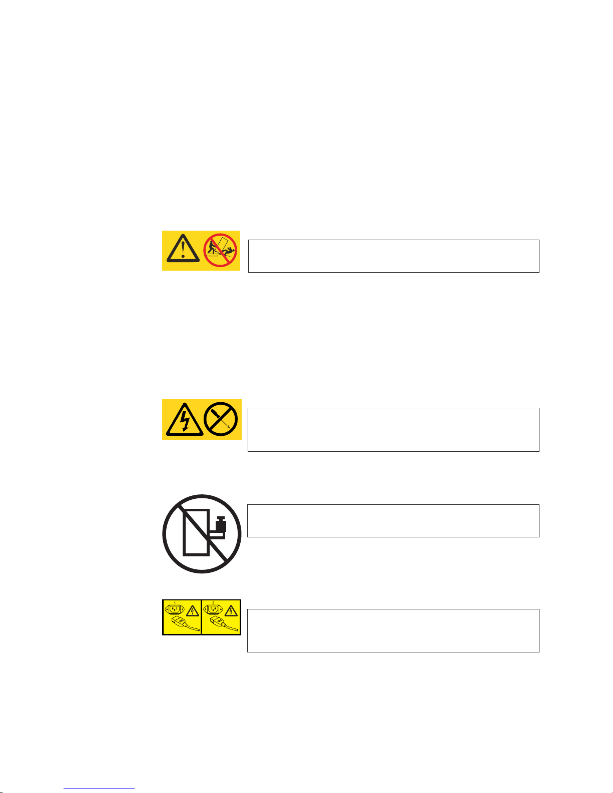
Caution notices
A caution notice calls attention to a situation that is potentially hazardous to people
because of some existing condition. A caution notice can be accompanied by
different symbols, as in the examples below:
If the symbol
is... It means....
A hazardous electrical condition with less severity than electrical danger.
A generally hazardous condition not represented by other safety symbols.
A specification of product weight that requires safe lifting practices. The
weight range of the product is listed below the graphic, and the wording
of the caution varies, depending on the weight of the device.
55 kg ( 121.2 lbs)
>55kg (121.2 lb)
P/N 18P5850-B
svc00169
A potential hazard of pinching the hand or other body parts between
parts.
SJ000752
A hazardous condition due to moving parts nearby.
xii IBM x-series of Ethernet Switches Installation and User Guide
Page 15

If the symbol
is... It means....
A hazardous condition due to the use of a laser in the product. Laser
symbols are always accompanied by the classification of the laser as
defined by the U.S. Department of Health and Human Services (for
example, Class I, Class II, and so forth).
Read and comply with the following caution notices before installing or servicing this
device.
CAUTION:
Energy hazard present. Shorting may result in system outage and
possible physical injury. Remove all metallic jewelry before
servicing. (C001)
CAUTION:
This product is equipped with a 3-wire (two conductors and ground)
power cable and plug. Use this power cable with a properly
grounded electrical outlet to avoid electrical shock. (C018)
CAUTION:
Servicing of this product or unit is to be performed by trained
service personnel only. (C032)
Danger notices
A danger notice calls attention to a situation that is potentially lethal or extremely
hazardous to people. A lightning bolt symbol accompanies a danger notice to
represent a dangerous electrical condition. Read and comply with the following
danger notices before installing or servicing this device.
DANGER
To prevent a possible shock from touching two surfaces with
different protective ground (earth), use one hand, when possible,
to connect or disconnect signal cables. (D001)
DANGER
Overloading a branch circuit is potentially a fire hazard and a
shock hazard under certain conditions. To avoid these hazards,
ensure that your system electrical requirements do not exceed
branch circuit protection requirements. Refer to the information
that is provided with your device or the power rating label for
electrical specifications. (D002)
Preface xiii
Page 16

DANGER
If the receptacle has a metal shell, do not touch the shell until
you have completed the voltage and grounding checks. Improper
wiring or grounding could place dangerous voltage on the metal
shell. If any of the conditions are not as described, STOP. Ensure
the improper voltage or impedance conditions are corrected
before proceeding. (D003)
DANGER
An electrical outlet that is not correctly wired could place
hazardous voltage on metal parts of the system or the devices
that attach to the system. It is the responsibility of the customer
to ensure that the outlet is correctly wired and grounded to
prevent an electrical shock. (D004)
The following general electrical danger notice provides instructions on how to avoid
shock hazards when servicing equipment. Unless instructed otherwise, follow the
procedures in this danger notice.
xiv IBM x-series of Ethernet Switches Installation and User Guide
Page 17

DANGER
When working on or around the system, observe the following
precautions:
Electrical voltage and current from power, telephone, and
communication cables are hazardous. To avoid a shock hazard:
v Connect power to this unit only with the IBM provided power
cord. Do not use the IBM provided power cord for any other
product.
v Do not open or service any power supply assembly.
v Do not connect or disconnect any cables or perform
installation, maintenance, or reconfiguration of this product
during an electrical storm.
v The product might be equipped with multiple power cords. To
remove all hazardous voltages, disconnect all power cords.
v Connect all power cords to a properly wired and grounded
electrical outlet. Ensure that the outlet supplies proper voltage
and phase rotation according to the system rating plate.
v Connect any equipment that will be attached to this product to
properly wired outlets.
v When possible, use one hand only to connect or disconnect
signal cables.
v Never turn on any equipment when there is evidence of fire,
water, or structural damage.
v Disconnect the attached power cords, telecommunications
systems, networks, and modems before you open the device
covers, unless instructed otherwise in the installation and
configuration procedures.
v Connect and disconnect cables as described below when
installing, moving, or opening covers on this product or
attached devices.
To Disconnect:
1. Turn off everything (unless instructed otherwise).
2. Remove the power cords from the outlets.
3. Remove the signal cables from the connectors.
4. Remove all cables from the devices.
To Connect:
1. Turn off everything (unless instructed otherwise).
2. Attach all cables to the devices.
3. Attach the signal cables to the connectors.
4. Attach the power cords to the outlets.
5. Turn on the devices.
(D005)
If the weight of the product is greater than 227 kg (500 lb), the following statement
and notice apply. This could apply if multiple products are installed in a single
cabinet, and that cabinet and products needs to be moved.
Preface xv
Page 18
Delivery and subsequent transportation of the equipment: The customer
should prepare his environment to accept the new product based on the installation
planning information provided, with assistance from an IBM Installation Planning
Representative (IPR) or IBM authorized service provider. In anticipation of the
equipment delivery, the final installation site should be prepared in advance such
that professional movers/riggers can transport the equipment to the final installation
site within the computer room. If for some reason, this is not possible at the time of
delivery, the customer will need to make arrangements to have professional
movers/riggers return to finish the transportation at a later date. Only professional
movers/riggers should transport the equipment. The IBM authorized service provider
will only perform minimal frame repositioning within the computer room, as needed,
to perform required service actions. The customer is also responsible for using
professional movers/riggers in the case of equipment relocation or disposal.
DANGER
Heavy equipment—personal injury or equipment damage might
>(>)500 lbs. 227 kg.
result if mishandled. (D006)
a69i0333
Safety labels
As an added precaution, safety labels are often installed directly on products or
product components to warn of potential hazards. These can be either danger or
caution notices, depending upon the level of the hazard.
The actual product safety labels may differ from these sample safety labels:
DANGER
Hazardous voltage, current, or energy levels are present inside
any component that has this label attached. Do not open any
cover or barrier that contains this label. (L001)
DANGER
Rack-mounted devices are not to be used as a shelf or work
space. (L002)
DANGER
Multiple power cords. The product might be equipped with
multiple power cords. To remove all hazardous voltages,
disconnect all power cords. (L003)
xvi IBM x-series of Ethernet Switches Installation and User Guide
Page 19
DANGER
Hazardous voltage present. Voltages present constitute a shock
hazard, which can cause severe injury or death. (L004)
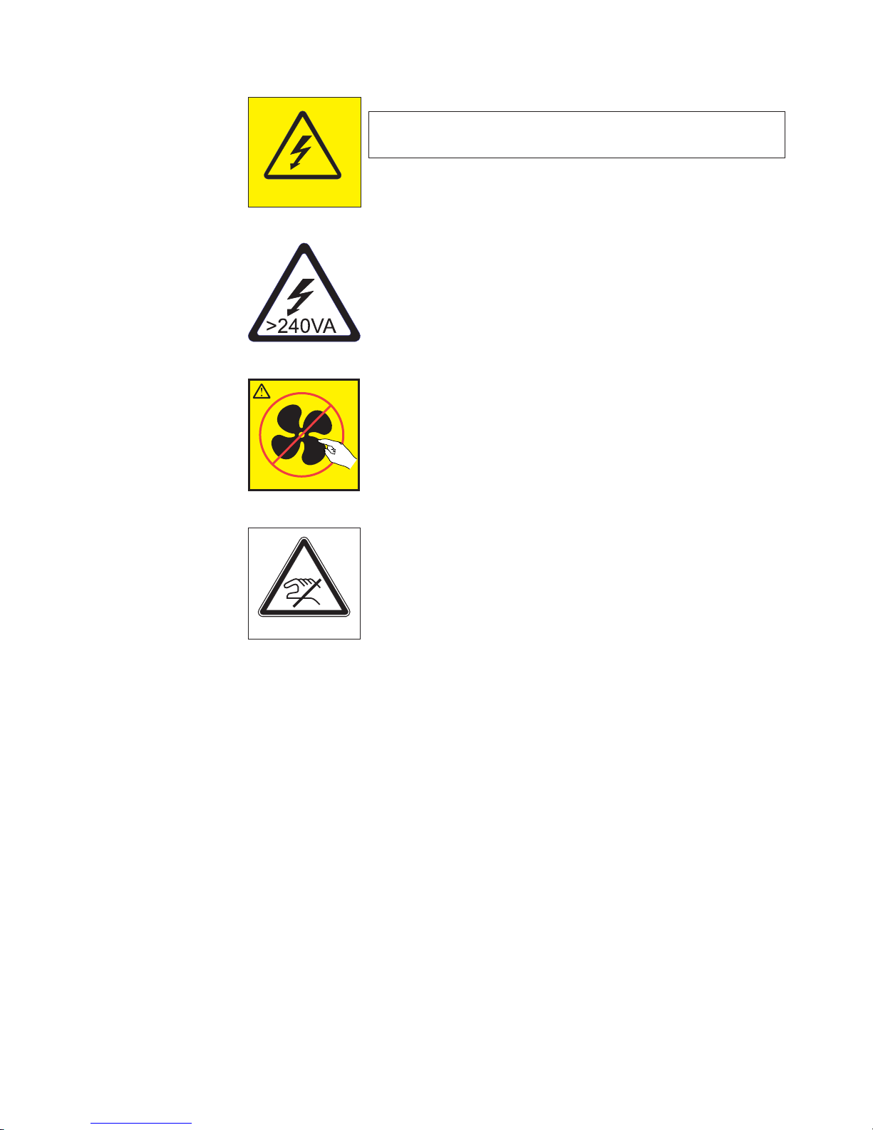
CAUTION:
Hazardous energy present. Voltages with hazardous energy might
cause heating when shorted with metal, which might result in
splattered metal, burns, or both. (L005)
CAUTION:
Hazardous moving parts nearby (L008)
P/N 18P5850-B
CAUTION:
Pinch hazard. (L012)
SJ000752
Preface xvii
Page 20

Rack safety
Rack installation
DANGER
Observe the following precautions when working on or around your IT rack system:
v Heavy equipment—personal injury or equipment damage might result if
mishandled.
v Always lower the leveling pads on the rack cabinet.
v Always install stabilizer brackets on the rack cabinet.
v To avoid hazardous conditions due to uneven mechanical loading, always install
the heaviest devices in the bottom of the rack cabinet. Always install servers and
optional devices starting from the bottom of the rack cabinet.
v Rack-mounted devices are not to be used as shelves or work spaces. Do not
place objects on top of rack-mounted devices.
v Each rack cabinet might have more than one power cord. Be sure to disconnect
all power cords in the rack cabinet when directed to disconnect power during
servicing.
v Connect all devices installed in a rack cabinet to power devices installed in the
same rack cabinet. Do not plug a power cord from a device installed in one rack
cabinet into a power device installed in a different rack cabinet.
v An electrical outlet that is not correctly wired could place hazardous voltage on
the metal parts of the system or the devices that attach to the system. It is the
responsibility of the customer to ensure that the outlet is correctly wired and
grounded to prevent an electrical shock.
(R001 part 1 of 2)
CAUTION:
v Do not install a unit in a rack where the internal rack ambient temperatures will
exceed the manufacturer’s recommended ambient temperature for all your
rack-mounted devices.
v Do not install a unit in a rack where the air flow is compromised. Ensure that air
flow is not blocked or reduced on any side, front, or back of a unit used for air flow
through the unit.
v Consideration should be given to the connection of the equipment to the supply
circuit so that overloading of the circuits does not compromise the supply wiring or
overcurrent protection. To provide the correct power connection to a rack, refer to
the rating labels located on the equipment in the rack to determine the total power
requirement of the supply circuit.
v (For sliding drawers) Do not pull out or install any drawer or feature if the rack
stabilizer brackets are not attached to the rack. Do not pull out more than one
drawer at a time. The rack might become unstable if you pull out more than one
drawer at a time.
v (For fixed drawers) This drawer is a fixed drawer and must not be moved for
servicing unless specified by the manufacturer. Attempting to move the drawer
partially or completely out of the rack might cause the rack to become unstable or
cause the drawer to fall out of the rack.
(R001 part 2 of 2)
xviii IBM x-series of Ethernet Switches Installation and User Guide
Page 21

Rack relocation (19″ rack)
CAUTION:
Removing components from the upper positions in the rack cabinet improves
rack stability during relocation. Follow these general guidelines whenever you
relocate a populated rack cabinet within a room or building:
v Reduce the weight of the rack cabinet by removing equipment starting at
the top of the rack cabinet. When possible, restore the rack cabinet to the
configuration of the rack cabinet as you received it. If this configuration is
not known, you must do the following:
– Remove all devices in the 32U position and above.
– Ensure that the heaviest devices are installed in the bottom of the rack
cabinet.
– Ensure that there are no empty U-levels between devices installed in the
rack cabinet below the 32U level.
– If the rack cabinet you are relocating is part of a suite of rack cabinets,
detach the rack cabinet from the suite.
– Inspect the route that you plan to take when moving the rack to
eliminate potential hazards.
– Verify that the route that you choose can support the weight of the
loaded rack cabinet. Refer to the documentation that came with your
rack cabinet for the weight of a loaded rack cabinet.
– Verify that all door openings are at least 760 x 2030 mm (30 x 80 in.).
– Ensure that all devices, shelves, drawers, doors, and cables are secure.
– Ensure that the four leveling pads are raised to their highest position.
– Ensure that there is no stabilizer bracket installed on the rack cabinet
during movement.
– Do not use a ramp inclined at more than 10 degrees.
– Once the rack cabinet is in the new location, do the following:
- Lower the four leveling pads.
- Install stabilizer brackets on the rack cabinet.
- If you removed any devices from the rack cabinet, repopulate the rack
cabinet from the lowest position to the highest position.
– If a long distance relocation is required, restore the rack cabinet to the
configuration of the rack cabinet as you received it. Pack the rack
cabinet in the original packaging material, or equivalent. Also, lower the
leveling pads to raise the casters off of the pallet and bolt the rack
cabinet to the pallet.
(R002)
Product recycling and disposal
Refer to the IBM Systems Environmental Notices and User Guide (Z125-5823) for
translated environmental statements and information regarding product recycling
and disposal. This document may be provided either in printed version or on the
product documentation CD.
See “Removing the battery” on page 38 for battery removal instructions, if needed
to meet environmental regulations.
Preface xix
Page 22

Product documents
The following documents contain information related to this product. The
documentation may be printed material or may be on the documentation CD that is
shipped with the product. Newer versions of product documentation may be
available through the IBM Publications Center web site www.ibm.com/shop/
publications/order or through the IBM Systems Networking Support web site
www.ibm.com/systems/support/networking. Search by product, publication title, or
publication number.
v IBM x-series of Ethernet Switches Installation and User Guide, GC27-2267 (this
document)
v IBM Systems Safety Notices, G229–9054
v IBM Systems Environmental Notices and User Guide, Z125-5823
v IBM Warranty
Software documents
IBM Ethernet switch and router products use software licensed from Brocade
Communications Systems, Inc. You can find software publications that support your
product on the CD-ROM supplied with this product.
The software publications associated with this product are:
v FastIron and TurboIron 24X Configuration Guide
v IronWare MIB Reference
These software publications reflect only the original Brocade products names. Use
the cross-reference of products in Table 1 to assist you when determining which
information in those publications applies to your product. Brocade products with no
IBM equivalents are not listed in the table. Note that the IBM products can be
ordered with additional features, while Brocade products with those additional
features may be offered as separate models.
Table 1. Comparable IBM and Brocade products.
IBM model
IBM
product
name
Ethernet
Router
B04M
Ethernet
Router
B08M
Ethernet
Router
B16M
Ethernet
Router
B32M
Ethernet
Switch
B04R
IBM
machine
type
4003 M04 4U modular Ethernet router with 4
4003 M08 7U modular Ethernet router with 8
4003 M16 14U modular Ethernet router with
4003 M32 33U modular Ethernet and IP
4003 R04 4U modular Ethernet switch with 4
(HVEC/XCC
model in
parentheses) Brief product description
interface slots
interface slots
16 interface slots
router with 32 interface slots
interface slots
Brocade
Brocade product
name
NetIron MLX-4 NI-MLX-4-AC
NetIron MLX-8 NI-MLX-8-AC
NetIron MLX-16 NI-MLX-16-AC
NetIron MLX-32 NI-MLX-32-AC-A
BigIron RX-4 BI-RX-4-AC
product part
number
xx IBM x-series of Ethernet Switches Installation and User Guide
Page 23

Table 1. Comparable IBM and Brocade products. (continued)
IBM model
IBM
product
name
Ethernet
Switch
IBM
machine
type
(HVEC/XCC
model in
parentheses) Brief product description
4003 R08 7U modular Ethernet switch with 8
interface slots
B08R
Ethernet
Switch
4003 R16 14U modular Ethernet switch with
16 interface slots
B16R
Ethernet
Switch
4003 R32 33U modular Ethernet switch with
32 interface slots
B32R
Ethernet
Switch
4003 S08 6U modular Ethernet switch with 8
interface slots
B08S
Ethernet
Switch
4003 S16 14U modular Ethernet switch with
16 interface slots
B16S
Ethernet
Switch
B24X
4002 X2A (4002AX2) 1U Ethernet switch with
twenty-four 10/1 GbE SFP+/SFP
ports plus four 10/100/1000 MbE
RJ45 ports
Ethernet
Switch
B24C (C)
4002 C2A (4002AC2) 1U Ethernet switch with
twenty-four 10/100/1000 MbE
RJ45 ports including four
combination 100/1000 MbE SFP
ports and one module slot for
optional 2-port 10 GbE XFP
module
Ethernet
Switch
B24C (F)
4002 C2B (4002BC2) 1U Ethernet switch with
twenty-four 100/1000 MbE SFP
ports including four combination
10/100/1000 MbE RJ45 ports and
one module slot for optional 2-port
10 GbE XFP module
Ethernet
Switch
B48C (C)
4002 C4A (4002AC4) 1U Ethernet switch with forty-eight
10/100/1000 MbE RJ45 ports
including four combination
100/1000 SFP ports
Ethernet
Switch
4002 C4B,
(4002BC4)
1U Ethernet switch with forty-eight
100/1000 MbE SFP ports
B48C (F)
Ethernet
Switch
B50C (C)
Ethernet
Switch
B50C (F)
4002 C5A,
(4002AC5)
4002 C5B,
(4002BC5)
1U Ethernet switch with forty-eight
10/100/1000 MbE RJ45 ports plus
two 10 GbE XFP ports
1U Ethernet switch with forty-eight
100/1000 MbE SFP ports plus two
10 GbE XFP ports
Brocade
Brocade product
name
product part
number
BigIron RX-8 BI-RX-8-AC
BigIron RX-16 BI-RX-16-AC-A
BigIron RX-32 I-RX-32-AC-A
FastIron SX 800 FI-SX800-AC
FastIron SX 1600 FI-SX1600-AC
Ethernet Switch
TI-24X-AC
B24X
NetIron CES 2024C NI-CES-
2024C-AC
NetIron CES 2024F NI-CES-
2024F-AC
NetIron CES 2048C NI-CES-
2048C-AC
NetIron CES 2048F NI-CES-
2048F-AC
NetIron CES
2048CX
NetIron CES
2048FX
NI-CES-
2048CX-AC
NI-CES-
2048FX-AC
Preface xxi
Page 24

Table 1. Comparable IBM and Brocade products. (continued)
IBM model
IBM
product
name
Ethernet
Switch
B48G
Ethernet
Switch
B50G
IBM
machine
type
4002 G4A,
4002 G5A,
(HVEC/XCC
model in
parentheses) Brief product description
(4002AG4)
(4002AG5)
1.5U Ethernet switch with
forty-eight 10/100/1000 MbE RJ45
(PoE capable) ports including four
combination 100/1000 MbE SFP
ports and one module slot for
optional 2-port 10 GbE (XFP or
CX4) module
1.5U Ethernet switch with
forty-eight 10/100/1000 MbE RJ45
(PoE capable) ports including four
combination 100/1000 MbE SFP
ports plus 2-port 10 GbE CX4
module supporting stacking
Brocade
Brocade product
name
FastIron GS FGS648P
FastIron GS-STK FGS648P-STK
product part
number
Accessibility features for the IBM x-series of Ethernet Switches
Accessibility features help users who have a disability, such as restricted mobility or
limited vision, to use information technology products successfully.
Accessibility features
Use and operation of this device is accomplished primarily through external devices
which may provide different accessibility features.
The following list includes the major accessibility features in the product either
directly or through external devices or interfaces:
v Keyboard-only operation
v Interfaces that are commonly used by screen readers
v Keys that are discernible by touch but do not activate just by touching them
v Industry-standard devices for ports and connectors
v The attachment of alternative input and output devices
Keyboard navigation
This product uses standard Microsoft®Windows®navigation keys.
Vendor software
These products include certain vendor software that is not covered under the IBM
license agreement. IBM makes no representation about the accessibility features of
these products. Contact the vendor for the accessibility information about its
products.
Related accessibility information
You can view the publications for these products in Adobe Portable Document
Format (PDF) using the Adobe Acrobat Reader. The PDFs are provided on a CD
that is packaged with the product. An accessible HTML version of this document is
also included on the documentation CD for this product.
xxii IBM x-series of Ethernet Switches Installation and User Guide
Page 25

IBM and accessibility
See the IBM Human Ability and Accessibility Center for more information about the
commitment that IBM has to accessibility: www.ibm.com/able.
Getting help
For the latest version of your product documentation, visit the web at
www.ibm.com/shop/publications/order. Search by form number or title.
For more information about this and other IBM products, visit the IBM web site:
www.ibm.com/
For support information for this product and other IBM products, see the following
web site: www.ibm.com/systems/support/. Select your product family, and follow the
web navigation to your specific product.
You can also contact IBM within the United States at 1-800-IBMSERV
(1-800-426-7378). For support outside the United States, you can find the service
number at: www.ibm.com/planetwide/.
Visit www.ibm.com/contact for the contact information for your country or region.
Taiwan Contact Information
IBM Taiwan Product Service Contact Info:
IBM Taiwan Corporation
3F, No 7, Song Ren Rd., Taipei Taiwan
Tel: 0800-016-888
How to send your comments
Your feedback is important in helping us provide the most accurate and high-quality
information. If you have comments or suggestions for improving this document,
send us your comments by e-mail to starpubs@us.ibm.com.
Be sure to include the following:
v Exact publication title
v Publication form number (for example, GC26-1234-02)
v Page, table, or illustration numbers
v A detailed description of any information that should be changed
About This Document
This guide describes the IBM x-series of Ethernet Switch products from IBM. It
provides procedures for installing the IBM Ethernet Switch B24X switch, cabling,
and performing a basic configuration of the switch. This guide also provides
information on managing and maintaining the switch. When reference to a specific
model is not required, the general terms switch, product,ordevice will be used to
Preface xxiii
Page 26

refer to all models. The term x-series may also be used when needed to
differentiate between different IBM Ethernet switch product lines.
Audience
This manual is designed for system administrators with a working knowledge of
Layer 2 and Layer 3 switching and routing.
You should be familiar with the following protocols if applicable to your network: IP,
RIP, OSPF, IS-IS, BGP4, MBGP, IGMP, PIM, DVMRP, IPX, AppleTalk, FSRP, VRRP,
and VRRPE.
Supported hardware and software
The following hardware platform is supported by this release of this guide:
v x-series of Ethernet switches Series
Document conventions
This section describes text formatting conventions and important notice formats
used in this document.
Text formatting
The narrative-text formatting conventions that are used are as follows:
Table 2. Formatting conventions
bold text Identifies command names
Identifies the names of user-manipulated GUI
elements
Identifies keywords
Identifies text to enter at the GUI or CLI
italic text Provides emphasis
Identifies variables
Identifies document titles
code text Identifies CLI output
For readability, command names in the narrative portions of this guide are
presented in bold: for example, show version.
Command syntax conventions
Command syntax in this manual follows these conventions:
Table 3. Command syntax conventions
command and
parameters
[ ] Optional parameter.
variable Variables are printed in italics enclosed in angled brackets < >.
... Repeat the previous element, for example “member[;member...]”
| Choose from one of the parameters.
Commands and parameters are printed in bold.
xxiv IBM x-series of Ethernet Switches Installation and User Guide
Page 27

Chapter 1. Product Overview
The IBM Ethernet Switch B24X provides high port density and 512 MB of DDR
RAM when shipped from the factory. The B24X delivers a full complement of
standards-based, feature-rich Layer 2 switching capability. The extensive feature set
supports network requirements ranging from basic connectivity to multicast- enabled
full streaming audio and video applications for converged services.
The B24X supports the following:
v Twenty-four SFP+ ports at either 1 GbE or 10 GbE using the standard E1MG
optics, as well as the new SFP+ 10GbE optics
v Four 10/100/1000 RJ-45 ports
Software features
Software features differ depending on the software version that is loaded on the
device. When first shipped, the devices support full Layer 2 Switching.
For a complete list of software features supported, refer to the release notes or the
FastIron and TurboIron 24X Configuration Guide.
Hardware features
This section describes the physical characteristics of the models. For details about
physical dimensions, power supply specifications, and pin-outs, refer to Appendix A,
“Hardware Specifications,” on page 43.
Figure 1 shows the B24X.
Figure 1. IBM Ethernet Switch B24X
The B24X contains the following ports:
v Twenty-four (24) SFP+ 10 Gigabit and Gigabit Ethernet fiber ports
v Four (4) 10/100/1000 Mbps copper ports, supporting 100Base-TX and
1000Base-T RJ-45 connectors
Mgmt
Console
netx001
© Copyright IBM Corp. 2009 1
Page 28

Control features
The B24X front panel has the following control features:
v Serial management interface-DB-9 connector interface (Console Port)
v 10/100/1000 RJ-45 Management Port
1 shows the Management port and 2 shows the Console port.
Mgmt
Console
A
netx002
1
Figure 2. Console and Management ports
Serial management interface (Console port)
The serial management interface (port labeled Console) enables you to configure
and manage the device using a third-party terminal emulation application on a
directly connected PC, straight-through EIA or TIA DB-9 serial cable (M/F) is
included. The console port is located in the upper right of the front panel.
Management port
The Management port provides connectivity to your existing management network
through 10/100/1000 copper ports that uses auto-sensing and auto-negotiating to
determine the speed (10 Mbps, 100 Mbps, or 1000 Mbps) and mode (full-duplex or
half-duplex) of the port at the other end of the link, and adjusts port speed
accordingly. The Management port on the B24X supports RJ-45 copper connectors,
auto MDI or MDIX detection, and has an RJ-45 unshielded twisted pair (UTP)
connector.
Note: This port interfaces with the CPU only and not the data plane.
Network interfaces
Table 4 describes the network interfaces supported on B24X devices. For network
interface specifications, refer to Table 13 on page 47.
2
Table 4. Network interfaces
Interface Show Media Description
1000Base-BX-D M-GBXD
1000Base-BX-U M-GBXU
1000Base-LHA M-LHA
1000Base-LHB M-LHB
1000Base-LX M-LX
1000Base-SX M-SX
1000Base-SX2 M-SX2
1000Base-T C
100Base-TX
10GBase-LR XG-LR
2 IBM x-series of Ethernet Switches Installation and User Guide
Page 29

Table 4. Network interfaces (continued)
Interface Show Media Description
10GBase-SR XG-SR
Viewing the media types installed in the ports
The show media command displays the types of media (copper or fiber) installed in
the ports. The following example is show media output.
FastIron# show media
Port 1: Type : 10G XG-SR(SFP+)
Vendor: Brocade Version: 1
Part# : PLRXPLSCS4371 Serial#: C833UQ06H
Port 2: Type : EMPTY
Port 3: Type : EMPTY
Port 4: Type : EMPTY
Port 5: Type : EMPTY
Port 6: Type : 10G XG-SR(SFP+)
Vendor: Brocade Version: 1
Part# : PLRXPLSCS4371 Serial#: C847UQ04C
Port 7: Type : 10G XG-SR(SFP+)
Vendor: Brocade Version: 1
Part# : PLRXPLSCS4371 Serial#: C847UQ04H
Port 8: Type : EMPTY
Port 9: Type : EMPTY
Port 10: Type : EMPTY
Port 11: Type : EMPTY
Port 12: Type : EMPTY
Port 13: Type : 10G XG-SR(SFP+)
Vendor: Brocade Version: 1
Part# : PLRXPLSCS4371 Serial#: C847UQ04T
Port 14: Type : 10G XG-SR(SFP+)
Vendor: Brocade Version: 1
Part# : PLRXPLSCS4371 Serial#: C847UQ04R
Port 15: Type : 10G XG-SR(SFP+)
Vendor: Brocade Version: 1
Part# : PLRXPLSCS4371 Serial#: C847UQ050
Port 16: Type : 10G XG-SR(SFP+)
Vendor: Brocade Version: 1
Part# : PLRXPLSCS4371 Serial#: C847UQ059
Port 17: Type : EMPTY
Port 18: Type : EMPTY
Port 19: Type : 10G XG-SR(SFP+)
Vendor: Brocade Version: 1
Part# : PLRXPLSCS4371 Serial#: C847UQ04K
Port 20: Type : 10G XG-SR(SFP+)
Vendor: Brocade Version: 1
Part# : PLRXPLSCS4371 Serial#: C833UQ068
Port 21: Type : EMPTY
Port 22: Type : EMPTY
Port 23: Type : EMPTY
Port 24: Type : EMPTY
Port 25: Type : 1G M-C (Gig-Copper)
Port 26: Type : 1G M-C (Gig-Copper)
Port 27: Type : 1G M-C (Gig-Copper)
Port 28: Type : 1G M-C (Gig-Copper)
10 Gbps ports
Ports1-24support 1-GbE SFP transceivers and 10-GbE SFP and SFP+
transceivers listed in Table 4 on page 2. 1 in Figure 3 on page 4 shows GbE ports
1-24, numbered from left to right.
Chapter 1. Product Overview 3
Page 30

Figure 3. 24 10-GbE ports
Four 10/100/1000 Mbps ports
The ports 25~28 are 10/100/1000 copper ports that use auto-sensing and
auto-negotiating to determine the speed (10 Mbps, 100 Mbps, or 1000 Mbps) and
mode (full-duplex or half-duplex) of the port at the other end of the link, and adjust
port speed accordingly.
10/100/1000 ports on the B24X support RJ-45 copper connectors. The output of the
show media command displays C next to the ports that have copper connectors
installed.
Gigabit copper ports on the B24X support auto MDI or MDIX detection. For more
information about this feature, refer to “Configuring MDI/MDIX” in the FastIron and
TurboIron 24X Configuration Guide.
Mgmt
Console
A
netx003
1
10GbE SFP+ transceiver
The B24X supports a 10GbE SFP+ transceiver specifically for ports 1-24. LEDs on
the module faceplates indicate operational status:
v If the LED is on, the port is connected. If the LED is off, no connection exists, or
the link is down.
v If the LED is on or blinking, traffic is being transmitted and received on the port.
LEDs for network interfaces and power supplies
The fiber and copper ports on the B24X provide status information through the
LEDs listed in Table 5. The following are the LEDs for network interfaces and power
supplies:
v 24 10-Gbps fiber ports (1~24 port) have LEDs located under each of them.
v Four 10/100/1000 copper ports (25~28) have Link and Activity LEDs to indicate
port status.
v The Management port has a Link LED and Activity LED to indicate port status.
The Link LED is on the left of the copper connector and the Activity LED is on
the right.
v The System power on LED is on the left side of the front panel.
v The dual power supply 1 and 2 LEDs are on the front panel of the power supply
(when you are facing the rear of the device).
Table 5. LEDs
LEDs Position State Meaning
10Gbps Port LEDs
4 IBM x-series of Ethernet Switches Installation and User Guide
Page 31

Table 5. LEDs (continued)
LEDs Position State Meaning
LNK or ACT Located under the
10-GbE ports
On The port is
connected.
Off No fiber port
connection exists or
the link is down.
Blinking Traffic is begin
transmitted or
received on the fiber
port.
10/100/1000 Copper Port LEDs
Lnk This is the left LED
on RJ45
On The port is
connected.
Off No copper port
connection exists or
the link is down.
Act This is the right LED
on RJ45
On or Blinking Traffic is being
transmitted or
received on the
copper port.
Off No traffic is being
transmitted or
received on the fiber
port.
Management Port LEDs
Lnk This is the left LED
on RJ45
On The port is
connected.
Off No copper port
connection exists or
the link is down.
Act This is the right LED
on RJ45
On or Blinking Traffic is being
transmitted or
received on the
copper port.
Off No traffic is being
transmitted or
received on the fiber
port.
System Power and Power Supply LEDs
Power On the upper left side
of the front panel
(when facing the front
of the device)
On The device is
powered on and has
enough power to
operate.
Off The device is not
powered on, or has
been powered on but
does not have
sufficient power to
operate.
Chapter 1. Product Overview 5
Page 32

Power supplies
Table 5. LEDs (continued)
LEDs Position State Meaning
AC OK Upper center of
power supply’s front
panel (when facing
the rear of the
device)
On Indicated power
supply is installed
and is functioning
normally.
Note: Power supply
1 is located in the
right-hand bay and
power supply 2 in the
left-hand bay (when
facing the rear of the
device).
Off Power supply is not
installed or is not
providing power.
Each B24X comes with one AC power supply installed, and a optional second
power supply for redundancy. See “Replacing AC power supplies” on page 34 for
instructions on installing a power supply.
Figure 4 shows the front panel of the AC power supplies used in the B24X. 1 is
the AC LED.
1
netx004
Figure 4. AC power supply front panel
The power supplies are auto-sensing and auto-switching, and provide up to 300
watts of total output power, having a universal input (90 VAC to 264 VAC) and 12
VDC regulated output.
Power supplies can be swapped in or out of the device while the device is running,
and without opening the device. You can remove one of the supplies without
interrupting operation because the remaining power supply provides enough power
for all of the ports.
For power supply hardware specifications, refer to “Power supply specifications” on
page 48.
6 IBM x-series of Ethernet Switches Installation and User Guide
Page 33

CAUTION:
Disconnect the power supply cable from the power source (outlet) before you
install it in or remove it from the device. Failure to do this can result in
damage to the power supply or the device, or both (the device can be running
while a power supply is being installed or removed, but the power supply
itself should not be connected to a power source).
Attention: The B24X power supply is designed exclusively for use with the B24X.
Installing the power supply in a device other than a B24X will cause extensive
damage to your equipment.
Chapter 1. Product Overview 7
Page 34

8 IBM x-series of Ethernet Switches Installation and User Guide
Page 35

Chapter 2. Installing the B24X
This chapter contains information on how to install the B24X switch.
Attention: Before starting any installation procedure, refer to “Safety notices” on
page xi.
Unpacking a system
Attention: The procedures in this manual are intended for qualified service
personnel.
Information about configuring IP addresses and connecting network devices is in
Chapter 3, “Connecting Network Devices and Checking Connectivity,” on page 19.
Systems ship with all of the items listed below. Please review the list and verify the
contents. If any items are missing, please contact the place of purchase.
Package contents
Verify the package contents listed below:
v IBM Ethernet Switch B24X device with dual AC power supplies installed
v AC power cord
v Rack mount brackets and mounting screws (already secured on the device)
v CD-ROM containing software images and user documentation (including this
guide)
v Warranty card
General requirements
To manage the system, you will need the following items for serial connection to a
Layer 2 or Layer 3 switch:
v A management station, such as a PC running a terminal emulation application.
v A serial cable (provided).
v Use the serial connection to perform basic configuration tasks, such as assigning
an IP address and network mask. This information is required to manage the
system using IronView Network Manager or using the CLI through Telnet.
Summary of installation tasks
Follow the steps listed in Table 6 to install your B24X device. Details for each of
these steps are provided in this chapter and in the following chapter.
Table 6. Summary of installation tasks
Task No. Task
1 Ensure that the physical
environment where the
device will be installed has
the proper cabling and
ventilation.
Where to Find More
Information
“Preparing the installation
site” on page 12
© Copyright IBM Corp. 2009 9
Page 36

Table 6. Summary of installation tasks (continued)
Where to Find More
Task No. Task
2 Install the device on a
desktop or in an equipment
rack. Devices may also be
wall-mounted.
3 When the device is installed,
plug the power cord into a
nearby power source that
adheres to the regulatory
requirements outlined in this
manual.
4 Verify that power LED is on
after the system is
powered-on.
5 Attach a terminal or PC to
the device. This enables you
to configure the device
through the Command Line
Interface (CLI).
6 No default password is
assigned to the CLI. For
additional access security,
assign a password.
7 Before attaching equipment
to the device, you must
configure an interface IP
address to the subnet on
which it will be located. Initial
IP address configuration is
performed using the CLI with
a direct serial connection.
8 Once you power-on the
device and assign IP
addresses, the system is
ready to accept network
equipment.
9 Test IP connectivity by
pinging other devices and
tracing routes.
10 Continue configuration using
the CLI. You also can use
IronView Network Manager to
manage the device.
11 Secure access to the device. FastIron and TurboIron 24X
Information
“Installing the device” on
page 12
“Powering on the system” on
page 14
“Verifying proper operation”
on page 14
“Attaching a PC or terminal”
on page 15
“Assigning permanent
passwords” on page 19
“Configuring IP addresses”
on page 20
“Connecting network devices”
on page 21
“Testing connectivity” on
page 24
FastIron and TurboIron 24X
Configuration Guide
Configuration Guide
Installation precautions
Attention: Before starting any installation procedure, refer to “Safety notices” on
page xi.
10 IBM x-series of Ethernet Switches Installation and User Guide
Page 37

General precautions
Attention: Do not install the device in an environment where the operating
ambient temperature might exceed 40°C (104°F).
Make sure that air flow around the front, sides, and back of the device is not
restricted.
Never leave tools inside the device.
Attention: Use the erase startup-config command only for new systems. If you
enter this command on a system you have already configured, the command
erases the configuration. If you accidentally do erase the configuration on a
configured system, enter the write memory command to save the running
configuration to the startupconfig file.
Power precautions
The following precautions apply to B24X devices:
Attention: Make sure you insert the power supply right-side up. It is possible to
insert the supply upside down, although the supply will not engage with the power
backplane cotter pin when plugged upside down. The label of the power supply is
on the top when you plug in the power supply right-side up when the power
connector is on the left and the fan vent is on the right.
Attention: Remove the power cord from a power supply before you install it in or
remove it from the device. Otherwise, the power supply or the device could be
damaged. (The device can be running while a power supply is being installed or
removed, but the power supply itself should not be connected to a power source.)
Attention: The B24X power supply is designed exclusively for use with B24X
devices. Installing the power supply in a device other than the B24X will cause
extensive damage to your equipment.
CAUTION:
The battery contains lithium. To avoid possible explosion, do not burn or
charge the battery.
Do not:
v Throw or immerse into water
v Heat to more than 100°C (212°F)
v Repair or disassemble
Exchange only with the IBM-approved part. Recycle or discard the battery
as instructed by local regulations. In the United States, IBM has a process
for the collection of this battery. For information, call 1-800-426-4333. Have
the IBM part number for the battery unit available when you call. (C003)
CAUTION:
Power supplies are hot swappable. However, IBM recommends that you
disconnect the power supply from AC power before installing or removing the
supply. The device can be running while a power supply is being installed or
removed, but the power supply itself should not be connected to a power
source. Otherwise, you could be injured or the power supply or other parts of
the device could be damaged.
Chapter 2. Installing the B24X 11
Page 38

CAUTION:
For safety reasons, the ESD wrist strap should contain a series 1 MB ohm
resistor.
Preparing the installation site
Ensure that any required facility electrical work has been completed before starting
the installation, and that there is adequate clear work space to accomplish the
installation.
Cabling infrastructure
Ensure that the proper cabling is installed in the site. Refer to “Device
specifications” on page 43 or visit www.ibm.com/systems/support/networking.
Installation location
Before installing the device, plan its location and orientation relative to other devices
and equipment. Allow at least 3 in. of space at the front of the device for the
twisted-pair, fiber-optic, and power cabling. Also, allow a minimum of 3 in. of space
between the sides and the back of the device and walls or other obstructions.
Installing the device
You can install switch devices on a desktop or in an equipment rack. See “Rack
safety” on page xviii before installing this device in a rack or cabinet.
Desktop installation
Complete the following steps for desktop installation:
1. Set the device on a flat desktop, table, or shelf. Make sure that adequate
ventilation is provided for the system. A 3 in. clearance is recommended on
each side.
2. Proceed to “Powering on the system” on page 14.
Rack mount installation
For rack mount installation, it is recommended that you use a Telco equipment rack.
The B24X device is compatible with two rack mount kits; a kit with short mounting
brackets that ships with the device, and long mounting brackets (not supplied) to
prevent the device from sagging when installed in a non-compliant (non-Telco)
equipment rack.
In addition to the rack mount kit, you will need the following tools for installation:
v #2 Phillips-head screwdriver
v Four 12-24 screws to mount the device in the rack.
Attention: Reduced Air Flow - Installation of the equipment in a rack should be
such that the amount of air flow required for safe operation of the equipment is not
compromised.
Complete the following steps to install the rack mount brackets and mount the
device in a rack:
1. Remove the rack mount kit from the shipping carton. The kit contains two
mounting brackets.
12 IBM x-series of Ethernet Switches Installation and User Guide
Page 39

2. Place the Network switch on a hard flat surface with the front panel facing you.
3. Attach a rack-mount bracket to one side of the Network switch with the supplied
screws. Then attach the other bracket to the other side.
Attention: Make sure you use the screws supplied with the mounting
brackets. Using the wrong screws could damage the B24X and would invalidate
your warranty.
Figure 5 shows how to attach the short mounting brackets.
Figure 5. Attaching the short mounting brackets
netx005
4. Mount the device in the rack as illustrated in Figure 6.
Note: Although Figure 6 shows a device with short mounting brackets, the
procedure for securing a device with long mounting brackets is the same.
Figure 6. Installing the device in a rack
5. Proceed to “Powering on the system” on page 14.
netx006
Chapter 2. Installing the B24X 13
Page 40

Powering on the system
Note that the outlet should be installed near the equipment and should be easily
accessible. Install the outlet using the following steps:
1. Ensure that all power supplies are fully and properly inserted.
2. Remove the power cord from the shipping package.
3. Attach the AC power cord to the AC connector on the rear panel as shown in
Figure 7.
Note: Align the locating notch on the underside of the AC power cord before
inserting.
4. Insert the power cord plug into a properly grounded 115V or 120V electrical
outlet.
Figure 7. Attaching the AC power cord
5. Repeat this procedure for the second power supply.
6. Verify the device is working properly (refer to “Verifying proper operation”).
Powering off the system
To turn an AC system off, unplug all power cords from the power source. There is
no power switch for the device.
Verifying proper operation
After you have installed any additional power supplies and powered on the system,
verify that the device is working properly.
1. Verify that the LEDs on the power supply and system power LED are solid
green.
2. Verify proper operation by observing the LEDs on the front panel.
14 IBM x-series of Ethernet Switches Installation and User Guide
netx007
Page 41

10 Gbps port LEDs should be lit while the device performs diagnostics. After the
diagnostics are complete, the LEDs will be dark except for those that are attached
by cables to other devices.
If the links on these cables are good and the connected device is powered on, the
link LEDs will light. Table 7 provides more details on specific LED conditions after
system start-up.
Observing the power status LEDs
Table 7 lists the device LEDs that show power status.
Table 7. Power LEDs
LEDs Position State Meaning
Pwr (Power) Left-most LED on the
front panel
AC OK On power supply 1
front panel
AC OK On power supply 2
front panel
On The device is
powered on and has
enough power to
operate.
Off The device is not
powered on, or has
been powered on but
does not have
sufficient power to
operate.
On Power supply 1 is
installed and is
functioning normally.
Power supply 1 is
located in the
right-hand bay (when
you are facing the
rear of the device).
Off Power supply 1 is not
installed or is not
providing power.
On Power supply 2 is
installed and is
functioning normally.
Power supply 2 is
located in the lefthand bay (when you
are facing the rear of
the device).
Off Power supply 2 is not
providing power.
The software regularly polls the hardware for power status information. You can
display the status information from any management session using the show
chassis CLI command. In addition, the software automatically generates a Syslog
message and SNMP trap if a status change occurs.
Attaching a PC or terminal
To assign an IP address, you must have access to the Command Line Interface
(CLI). The CLI is a text-based interface that can be accessed through a direct serial
connection to the device or through Telnet connections.
Chapter 2. Installing the B24X 15
Page 42

You will need to assign an IP address using the CLI. You can access the CLI by
attaching management station through a serial cable to the Console port. After you
assign an IP address, you can access the system through Telnet or IronView
Network Manager.
Complete the following steps to attach a management station using the serial port:
1. Use a straight-through cable to connect a PC or terminal to the male DB-9
serial port connector.
Note: You need to run a terminal emulation program on the PC.
2. Open the terminal emulation program and set the session parameters as
follows:
v Baud: 9600 bps
v Data bits: 8
v Parity: None
v Stop bits: 1
v Flow control: None
When you establish the serial connection to the system, press Enter to display the
CLI prompt in the terminal emulation window. For example:
TurboIron>
When you see one of these prompts, you are connected to the system and can
proceed to “Assigning permanent passwords” on page 19.
You can customize the prompt by changing the system name. Refer to the FastIron
and TurboIron 24X Configuration Guide.
If you do not see a prompt:
v Make sure the cable is securely connected to your PC and to the device.
v Check the settings in your terminal emulation program. In addition to the session
settings listed above, make sure the terminal emulation session is running on the
same serial port you attached to the device.
The EIA or TIA 232 serial communication port serves as a connection point for
management by a PC or SNMP workstation. The switches come with a standard
male DB-9 connector, shown in Figure 8 on page 17.
16 IBM x-series of Ethernet Switches Installation and User Guide
Page 43

Pin assignment
Pin number Switch signal
1
DB-9 male
5
96
Figure 8. Serial port pin and signalling details
Most PC serial ports also require a cable with a female DB-9 connector.
Terminal connections will vary, requiring either a DB-9 or DB-25 connector, male or
female.
Serial cable options between a switch or router and a PC or terminal are shown in
Figure 9.
DB-9 to DB-9
Female switch
Terminal or PC
1
2
3
4
5
6
7
8
9
DB-9 to DB-25
Female switch
Reserved
TXD (output)
RXD (input)
Reserved
GND
Reserved
CTS (input)
RTS (output)
Reserved
net_com004
Terminal or PC
1
Reserved
2
3
4
Reserved
5
6
Reserved
7
8
9
Figure 9. Serial port pin assignments showing cable connection options to a terminal or PC
Reserved
1
2
3
4
5
6
7
8
9
1
Reserved
2
3
4
Reserved
5
6
Reserved
7
8
9
Reserved
8
3
2
20
7
6
4
5
22
net_com005
Note: As indicated in Figure 8 and Figure 9, some of the wires should not be
connected. If you do connect the wires that are labeled "Reserve”, you might
get unexpected results with some terminals.
Chapter 2. Installing the B24X 17
Page 44

18 IBM x-series of Ethernet Switches Installation and User Guide
Page 45

Chapter 3. Connecting Network Devices and Checking
Connectivity
This chapter provides the details for connecting network devices and checking
network connectivity.
Attention: The procedures in this manual are intended for qualified service
personnel.
Assigning permanent passwords
By default, the CLI is not protected by passwords. To secure CLI access, IBM
strongly recommends assigning passwords.
Note: You can assign passwords using IronView Network Manager if an enable
password for a Super User has been configured on the device.
The CLI contains the following access levels:
v User EXEC-The level you enter when you first start a CLI session. At this level,
you can view some system information but you cannot configure system or port
parameters.
v Privileged EXEC-Also called the Enable level, and can be secured by a
password. At this level, you can perform tasks such as manage files on the flash
module, save the system configuration to flash, and clear caches.
v CONFIG-This level lets you configure the system IP address, and switching and
routing features. To access the CONFIG mode, you must already be logged into
the Privileged level of the EXEC mode (the Enable level).
You can set the following levels of Enable passwords:
v Super User - Allows complete read-and-write access to the system. This is
generally for system administrators and is the only password level that allows
you to configure passwords.
Note: You must set a super user password before you can set other types of
passwords.
v Port Configuration - Allows read-and-write access for specific ports but not for
global (system-wide) parameters.
v Read Only - Allows access to the Privileged EXEC mode and CONFIG mode but
only with read access.
Complete the following steps to set passwords:
1. At the opening CLI prompt, enter the following command to change to the
Privileged level of the EXEC mode.
TurboIron> enable
2. Access the CONFIG level of the CLI by entering the following command.
TurboIron# configure terminal
TurboIron(config)#
3. Enter the following command to set the super-user password.
TurboIron(config)# enable super-user-password <text>
Note: You must set the super user password before you can set other types of
passwords.
© Copyright IBM Corp. 2009 19
Page 46

4. Enter the following commands to set the port configuration and read-only
passwords.
TurboIron(config)# enable port-config-password <text>
TurboIron(config)# enable read-only-password <text>
Note: If you forget your super user password, refer to “Recovering from a lost
password.”
Syntax: enable super-user-password | read-only-password |
port-config-password <text>
Passwords can be up to 32 characters long.
Recovering from a lost password
By default, the CLI does not require passwords. However, if someone has
configured a password for the device but the password has been lost, you can
regain super-user access to the device using the following procedure.
Note: Recovery from a lost password requires direct access to the serial port and a
system reset.
Complete the following steps to recover from a lost password:
1. Start a CLI session over the serial interface to the device.
2. Reboot the device.
3. While the system is booting, before the initial system prompt appears, enter b to
enter the boot monitor mode.
4. Enter no password at the prompt. (You cannot abbreviate this command.)
5. Enter boot system flash primary at the prompt. This command causes the
device to bypass the system password check.
6. After the console prompt reappears, assign a new password.
Configuring IP addresses
You must configure at least one IP address using the serial connection to the CLI
before you can manage the system using the other management interfaces. In
addition, routers require an IP subnet address for the subnet in which you plan to
place them in your network.
The x-series devices support both classical IP network masks (Class A, B, and C
subnet masks, and so on) and Classless Interdomain Routing (CIDR) and network
prefix masks as follows:
v To enter a classical network mask, enter the mask in IP address format. For
example, for an IP address with a Class-C subnet mask enter the following:
209.157.22.99 255.255.255.0
v To enter a prefix number for a network mask, enter a forward slash(/)andthe
number of bits in the mask immediately after the IP address. For example, enter
the following for an IP address that has a network mask with 24 significant
(“mask”) bits:
209.157.22.99/24
By default, the CLI displays network masks in classical IP address format (example:
255.255.255.0). You can change the display to the prefix format. Refer to the
FastIron and TurboIron 24X Configuration Guide.
20 IBM x-series of Ethernet Switches Installation and User Guide
Page 47

Devices running Layer 2 software
Complete the following steps to configure an IP address on a device running Layer
2 software:
1. At the opening CLI prompt, enter enable.
TurboIron> enable
2. Enter the following command at the Privileged EXEC level prompt (for example,
TurboIron Switch#), then press Enter. This command erases the factory test
configuration if still present.
TurboIron# erase startup-config
Attention: Use the erase startup-config command only for new systems. If
you enter this command on a system you have already configured, the
command erases the configuration. If you accidentally do erase the
configuration on a configured system, enter the write memory command to save
the running configuration to the startup-config file.
3. Access the configuration level of the CLI by entering the following command.
TurboIron# configure terminal Privileged EXEC Level
TurboIron(config)# Global CONFIG Level
4. Configure the IP address and mask for the switch.
TurboIron(config)# ip address 192.22.3.44 255.255.255.0
5. Set a default gateway address for the switch.
TurboIron(config)# ip default-gateway 192.22.3.1
Note: You do not need to assign a default gateway address for single subnet
networks.
Syntax: enable [<password>]
Syntax:configure terminal
Syntax:[no] ip address <ip-addr> <ip-mask>
or
Syntax:[no] ip address <ip-addr>/<mask-bits>
Syntax: ip default-gateway <ip-addr>
Connecting network devices
IBM devices support connections to routers, switches, and hubs from other vendors,
as well as other IBM devices.
Connectors and cable specifications
Refer to “Cable specifications” on page 46 for cable lengths and types supported on
the B24X devices. For port pinouts, refer to “10/100/1000 Gigabit port pinouts” on
page 46.
Connecting to Ethernet or fast Ethernet hubs
For copper connections to Ethernet hubs, a 10/100Base-TX or 1000Base-T switch,
or another device, a crossover cable is required (Figure 10 on page 22 and
Chapter 3. Connecting Network Devices and Checking Connectivity 21
Page 48

UTP crossover cable
10/100BaseTX
1
Figure 11). If the hub is equipped with an uplink port, it will require a
straight-through cable instead of a crossover cable.
Note: The 802.3ab standard (automatic MDI or MDIX detection) calls for automatic
negotiation of the connection between two 1000Base-T ports. Therefore, a
crossover cable may not be required; a straight-through cable may work as
well. For more information about this feature, refer to the FastIron and
TurboIron 24X Configuration Guide.
11
2
33
8
unused 4
unused 5
66
unused 7
unused 8
2
4 unused
5 unused
7 unused
8 unused
Figure 10. 10 UTP crossover cable
Cat-5 crossover cable
1000BaseT
2
1
Figure 11. Cat-5 crossover cable for 1000Base-T
8
33
4
5
6
7
8
Note: The 802.3ab standard calls for automatic negotiation of the connection
between two 1000Base-T ports. Consequently, a crossover cable may not be
required; a straight-through cable may work as well.
net_com007
11
2
4
5
6
7
8
net48bg028
22 IBM x-series of Ethernet Switches Installation and User Guide
Page 49

Connecting to workstations, servers, or routers
Straight-through UTP cabling is required for direct UTP attachment to workstations,
servers, or routers using network interface cards (NICs).
Fiber cabling is required for direct attachment to Gigabit NICs or switches and
routers through fiber ports. Refer to “Connecting a network device to a fiber port.”
Automatic MDI or MDIX detection
All 10/100/1000 Copper ports on the B24X devices support automatic Media
Dependent Interface (MDI) and Media Dependent Interface Crossover (MDIX)
detection. This feature is enabled on all Gigabit copper ports by default. For each
port, you can disable auto MDI or MDIX, designate the port as an MDI port, or
designate the port as an MDIX port.
For more information about this feature and how configure it, refer to the FastIron
and TurboIron 24X Configuration Guide.
Connecting a network device to a fiber port
For direct attachment from the device to a Gigabit NIC, switch, or router, fiber
cabling with an LC connector is required.
To connect the device to another network device using a fiber port, you must do the
following:
v Install a fiber optic module (SFP transceiver or mini-GBIC for Gigabit Ethernet
ports, or SFP+ transceiver for 10-Gigabit Ethernet ports)
v Cable the fiber optic module
The following sections provide information about performing these tasks.
Installing a fiber optic module: You must install a fiber optic module (SFP or
SFP+ transceiver) in each Gigabit Ethernet and 10-Gigabit Ethernet fiber port you
want to use.
You can install a new fiber optic module in a port while the device is powered on
and running.
To install a fiber optic module, you will need an ESD wrist strap with a plug for
connection to a metal surface.
CAUTION:
For safety reasons, the ESD wrist strap should contain a series 1 meg ohm
resistor.
Complete the following steps to install a fiber optic module:
1. Put on the ESD wrist strap and ground yourself by attaching the clip end to a
metal surface (such as an equipment rack) to act as ground.
2. Remove the new module from its protective packaging.
3. Gently insert the fiber optic module into the port until the module clicks into
place. The module is keyed to prevent incorrect insertion.
Cabling a fiber optic module: Complete the following steps to cable a fiber optic
module:
Chapter 3. Connecting Network Devices and Checking Connectivity 23
Page 50

1. Remove the protective covering from the fiber-optic port connectors and store
the covering for future use.
2. Before cabling a fiber optic module, clean the cable connectors and the port
connectors thoroughly. For more information, refer to “Cleaning the fiber-optic
connector.”
3. Gently insert the cable connector or connectors (a tab on each connector
should face upward) into the port connector or connectors until the tabs lock
into place.
4. Observe the link and active LEDs to determine if the network connections are
functioning properly. Refer to Table 8 on page 25.
Cleaning the fiber-optic connector: To avoid problems with the connection
between the fiber optic module (SFP (mini-GBIC) or SFP+) and the fiber cable
connectors, clean both connectors thoroughly each time you disconnect and
reconnect them. In particular, dust can accumulate in the connectors and cause
problems such as reducing the optic launch power.
When not using an SFP or SFP+ connector, make sure to keep the protective
covering on.
Testing connectivity
After you install the network cables, you can test network connectivity to other
devices by pinging those devices. You also can observe the LEDs related to
network connection and perform trace routes.
Pinging an IP address
To verify that a device can reach another device through the network, enter a
command such as the following at any level of the CLI on the device.
TurboIron> ping 192.33.4.7
Syntax: ping <ip addr> | <hostname> [source <ip addr>] [count <num>]
[timeout <msec>] [ttl <num>] [size <byte>] [quiet] [numeric] [no-fragment]
[verify] [data <1-to-4 byte hex>] [brief]
Note: If you address the ping to the IP broadcast address, the device lists the first
four responses to the ping.
Observing LEDs
After you install the network cables, you can observe certain LEDs to determine if
the network connections are functioning properly. Table 8 on page 25 describes the
LEDs related to network connections, the desired state of each LED, possible
abnormal states of each LED, and what to do if an LED indicates an abnormal
state.
24 IBM x-series of Ethernet Switches Installation and User Guide
Page 51

Table 8. Network connection-related LED states
LED Desired State Meaning
Link (Lnk) On (Green) A link is
established with
the remote port.
Active (Act) On or blinking
(Yellow)
The port is
transmitting and
receiving user
packets.
Abnormal
State Meaning or Action
Off A link is not established with the remote
port. You can do the following:
v Verify that the connection to the other
network device has been properly made.
Also, make certain that the other network
device is powered on and operating
correctly.
v Verify that the transmit port on the
device is connected to the receive port
on the other network device, and that the
receive port on the device is connected
to the transmit port on the other network
device. If you are uncertain, remove the
two cable connectors from the port
connector and reinsert them in the port
connector, reversing their order.
v Dust may have accumulated in the cable
connector or port connector. For
information about cleaning the
connectors, refer to “Cleaning the
fiber-optic connector” on page 24.
v If the other actions don’t resolve the
problem, try using a different port or a
different cable.
Off for an
extended
period.
The port is not transmitting or receiving
user packets. You can do the following:
v Check the Link LED to make sure the
link is still established with the remote
port. If not, take the actions described in
the Meaning or Action column for the
Link LED.
v Verify that the port has not been
disabled through a configuration change.
You can use the CLI. If you have
configured an IP address on the device,
you also can use IronView Network
Manager.
If a problem persists after taking these actions, contact IBM technical support.
Tracing a route
To determine the path through which a device can reach another device, enter a
command such as the following at any level of the CLI on the device.
TurboIron> traceroute 192.33.4.7
Syntax:traceroute <host-ip-addr> [maxttl <value>] [minttl <value>]
[numeric] [timeout <value>] [source-ip <ip addr>]
The CLI displays trace route information for each hop as soon as the information is
received. Traceroute requests display all responses to a given TTL. In addition, if
there are multiple equal-cost routes to the destination, the device displays up to
three responses by default.
Chapter 3. Connecting Network Devices and Checking Connectivity 25
Page 52

Troubleshooting network connections
v For the indicated port, verify that both ends of the cabling (at the device and the
connected device) are snug.
v Verify that the device and the connected device are both powered on and
operating correctly.
v Verify that you have used the correct cable type for the connection:
– For twisted-pair connections to an end node, use straight-through cabling.
– For fiber-optic connections, verify that the transmit port on the device is
connected to the receive port on the connected device, and that the receive
port on the device is connected to the transmit port on the connected device.
v Verify that the port has not been disabled through a configuration change. You
can use the CLI. If you have configured an IP address on the device, you also
can use IronView Network Manager.
v For copper ports, you can test the cable using Virtual Cable Testing (VCT). Refer
to “Monitoring Hardware Components” in the FastIron and TurboIron 24X
Configuration Guide.
v If the other procedures don’t resolve the problem, try using a different port or a
different cable.
Support for digital optical monitoring
You can configure your device to monitor optical transceivers in the system, either
globally or by specified port. When this feature is enabled, the system monitors the
temperature and signal power levels for the optical transceivers in the specified
ports. Console messages and syslog messages are sent when optical operating
conditions fall below or rise above the SFP+ or SFP manufacturer recommended
thresholds. For more information about digital optical monitoring, refer to the
FastIron and TurboIron 24X Configuration Guide.
26 IBM x-series of Ethernet Switches Installation and User Guide
Page 53

Chapter 4. Managing the B24X
This chapter contains information about how to manage temperature settings and
how to remove MAC address entries.
Managing temperature settings
This section describes how to display temperature settings on the B24X and how to
change the temperature warning levels.
Using the temperature sensor
The B24X comes with two built-in temperature sensors; one at the air intake, and
the other at the exhaust (refer to Figure 27 on page 44). The temperature sensor at
the air intake monitors the incoming air temperature. The temperature sensor at the
air exhaust monitors the air temperature as it exits the device. The temperature
sensors cause the device to generate a Syslog message and SNMP trap if the
temperature exceeds a specified warning level The software reads the temperature
sensors according to the device poll time, which is 60 seconds by default. If the
temperature equals or exceeds the warning temperature the software generates a
Syslog message and SNMP trap.
You can use the CLI to perform the following:
v “Displaying the temperature”
v “Changing the temperature warning level” on page 28
v “Changing the device temperature polling interval” on page 28
Displaying the temperature
By default, the software polls the temperature sensor every 60 seconds to get the
current temperature. This poll rate is controlled by the device poll time, which also
controls how often the software polls other system components.
To display the temperature of a device, enter the show chassis command at any
level of the CLI. The following shows an example output.
TurboIron#show chassis
Power supply 1 (NA - NA - Regular) present, status ok
Power supply 2 not present
Fan 1 ok, speed (auto):