

Page 1

3745 Communication Controller All Models
3746 Nways Multiprotocol Controller Model
900
-~-.-
----
- -
---
-
-.
- --
-----
----,-
---
---
---
Connection
and
Integration Guide
I
SA33-0129-10
Page 2

3745 Communication Controller All Models
3746 Nways Multiprotocol Controller Model
900
----
----
- -
---
- -
- --
-----
--_.-
---
---
---
"
o
o
Connection
and
Integration Guide
o
o
SA33-0129-10
Page 3
Note!
Before using this information and the product it supports, be sure to read the general information under
"Notices"
--------------------------------------------------------------------~
on
page xi.
o
,
•
Eleventh Edition (May 1997)
The information contained in this guide is subject to change from time to time. Any such changes will be reported
Order publications through your IBM representative or the IBM branch office serving your locality. Publications are not stocked at the
address given below.
A form for readers' comments appears at the back of this publication.
IBM France
. Centre d'Etudes
Service
0798 - BP 79
06610 La Gaude,
France
• FAX: 33 4 93 24 77 97
• E-mail: FRIBMQF5 at IBMMAIL
• IBM Internal
• Internet:
When you send information to
appropriate without incurring any obligation to you.
© Copyright International Business Machines Corporation 1988, 1997. All rights reserved.
Note to U.S. Government Users - Documentation related to restricted rights - Use, duplication
restrictions set forth in
et
Recherches
Use: LGERCF at LGEPROFS
rcUagaude@vnetibm.com
IBM, you grant IBM a non-exclusive right to use or distribute the information
GSA ADP Schedule Contract with IBM Corp.
If the form has been removed, address your comments
or
disclosure
in
later revisions.
in
any way it believes
is
subject to
to:
o
Page 4
o Contents
•
c
o
I
10
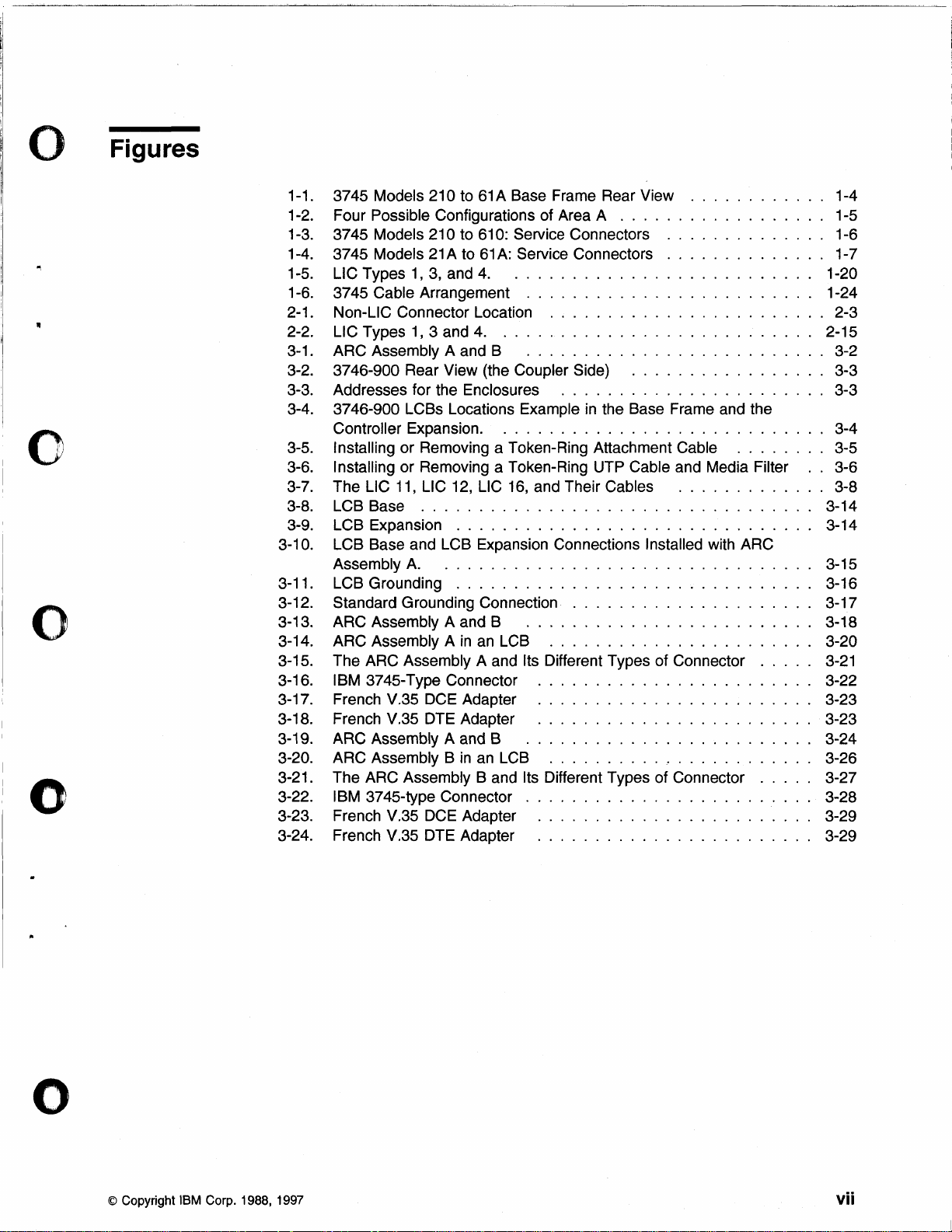
Figures
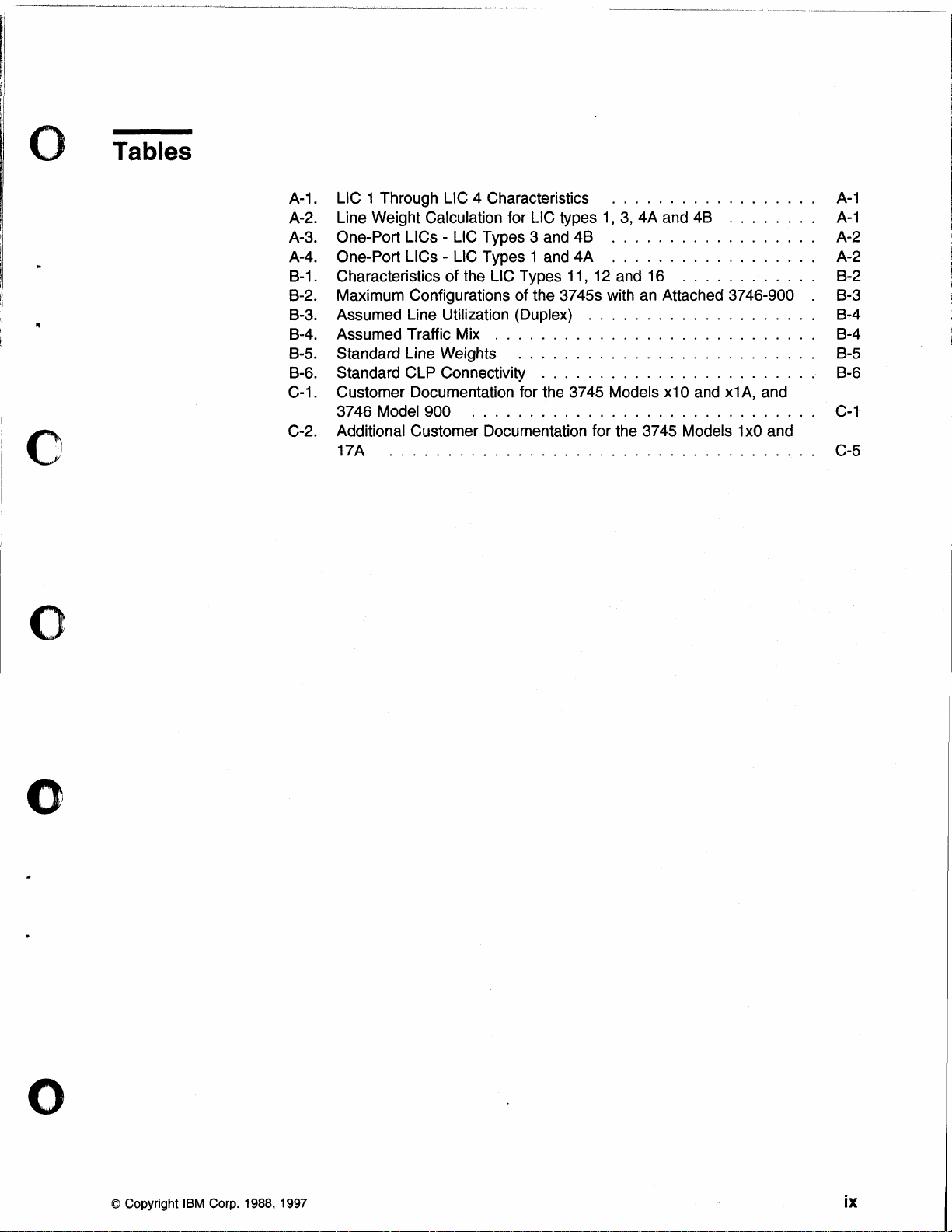
Tables
Notices
European Union (EU) Statement
Electronic Emission Notices
Trademarks and Service Marks
Safety
About
Conventions Used
Who Should Use this Guide . . . . . . . . . . . . . . . . . . . . . . . . . . . .
How this Guide
What is New
Where to Find More
Part 1. Connecting
Chapter 1. 3745 Models 210
Getting Started
Unplugging or Plugging
Unplugging or Plugging
Unplugging or Plugging
Unplugging or Plugging
Unplugging or Plugging
Removing or Installing the Customer Power Control (CPC) Cable
Removing or
Chapter
Getting Started
Unplugging or Plugging
Unplugging or Plugging
Unplugging or Plugging
Unplugging or Plugging
Unplugging or Plugging
Removing or
Removing or
..........................................
............................
...............................
...........................
..........................................
Safety Notices for United Kingdom
this
Guide
in
World Wide Web
Installing a Line Interface Coupler (LlC) or Its Cable
2.
3745 Models 130
Installing the Customer Power Control (CPC) Cable
Installing a Line Interface Coupler (LlC) or Its Cable
...................................
in
this Guide
is
Organized
this Guide
Information
.....................................
.....................................
.............................
..................................
In
an
In
a Token-Ring Adapter (TRA) Cable
In
a High-Speed Scanner (HSS) Cable
In
an
In
the Remote Support Facility (RSF) Cable
In
an
In
a Token-Ring Adapter (TRA) Cable
In a High-Speed Scanner (HSS) Cable
In
an
In
the Remote Support Facility (RSF) Cable
...........................
.............................
...........................
to
61A: Connecting LICs and Cables
Ethernet
Operator Console Cable
to
17A: Connecting LlCs and Cables
Ethernet
Operator Console Cable
........................
LAN
AUI Cable
LAN
AUI Cable
..............
........
........
.............
..............
.........
.........
..............
.......
........
.....
......
......
.....
......
......
vii
ix
xi
xi
xi
xii
xiii
xiii
xv
xv
..
xv
xvi
" xvi
xvii
xvii
1-1
1-2
1-7
1-11
1-13
1-15
1-16
1-18
1-18
2-1
2-2
2-4
2-7
2-8
2-9
2-11
2-12
2-13
o
Chapter
Connection Tasks
Starting Connection Tasks
Unplugging or Plugging
Unplugging or Plugging
Unplugging or Plugging
Unplugging
© Copyright IBM Corp. 1988, 1997 iii
3.
3746-900: Installing LCBs and ARCs, Connecting Cables
...................................
in
in
In
Unplugging or Plugging
or
Plugging
..............................
a TIC3 Cable
LlC Cables
an
Ethernet
In
an
AUI Cable
In
a 10BASE-T Cable
......................
........................
LAN
Cable
.....................
................
................
...
3-1
3-2
3-2
3-5
3-7
3-9
3-9
3-11
Page 5
Part
2.
Integrating
Unplugging or Plugging
Installing an LC8
Removing
Removing
or
or
...................................
Installing ARC Assembly A . . . . . . . . . . . . . . . . . .
Installing ARC Assembly 8 . . . . . . . . . . . . . . . . . .
in
a Multiaccess Enclosure Adapter Cable
......
..
..
3-12
3-13
3-18
3-24
'(.),"
"'__
'
Chapter
Starting Procedure
Chapter
MOSS-E Integration Functions (3746-900 Only) .
Updating the Active CDF-E (3746-900 Only)
Saving the Controller Configuration
MOSS Integration Procedures . . . . . . . . . . . . . . . . 5-5
Upgrading
Changing Passwords
Setting Power
Updating Link
IPL and Loading the Network Control Program
Saving
Putting the MOSS On-Line
4.
Starting the 3745 Integration
..........
5.
Integration Procedures
I nitial Installation
Integrating
I ntegrating a Later Modification
Conventions Used
When to Use Upgrade or Update
Upgrade
Update
IPL Ports on 3745 (All Models)
Link
an
or
Updating CDF
Procedure
Procedure
On
IPL Ports
IPL Ports on 3746-900. .
MOSS from Fixed Disk onto Diskettes
........................
Initial Installation
in
this Chapter for the MOSS
..................
............
.......................
on
the 3745 MOSS
Schedule
.....................
.......................
....................
.
...............
...........
..............
.............
...............
................
...........
.....
.......
........
....
.
.
.
.
.
.
.
.
. . . . .
.
.
. 5-16
.
.
. 5-18
.
.
.
4-1
4-1
5-1
5-1
5-1
5-1
5-5
5-6
5-6
5-6
5-7
5-7
5-8
5-10
5-14
5-17
5-17
5-18
5-19
5-21
\"----
If
/
Part
3.
iv 3745
Appendices
Appendix A. LSS Characteristics and Line Weights
Characteristics of the LSSs
Line Weight Calculation
Scanner Capacity
Appendix B. Communication Line Processor Characteristics and Line
Weights
Characteristics of the CLPs
Configuring Communication Lines
Appendix
All
Models & 3746-900: CIG
............
.............................
...............................
.............
Mixing Line
Spare Lines
Selective Scanning . . . . . . . . . . . . . . . . . . . . . . . . . . .
Interface Couplers
.......
...........................
.............................
Communication Line Processor Connectivity
Characteristics of
Maximum Configuration of a 3745 with a
CF3745 Hardware Configurator (Standard Line Weights)
C.
L1C
Types
Bibliographies
11,
on
;.
. . . . . . . . . . . . . . . . . .
.........................
. . . . . . . . . . . . . . . . A-3
.................
12, and 16
the 3746-900 (Line Weights)
..
. . . . . . . . . . . . . .
3746-900
.............
......
..
......
..
..
..
A-1
A-1
A-1
A-2
A-3
A-3
8-1
8-1
8-1
8-2
8-3
8-4
8-4
C-1
Page 6
o
Customer Documentation for the IBM 3745 (Models
31A, 41A, and 61A), and 3746
Additional Customer Documentation for the IBM 3745 Models 130, 150, 160,
170,
and 17A
Abbreviations, Glossary, and Index
....................................
(Model 900)
210,310,410,610,
....
. . . . . . . . . . . . .
21A,
..
C-1
C-5
•
o
o
List of Abbreviations
Glossary
Index
..........................................
X-1
X-3
X-9
o
o
Contents V
Page 7

•
vi
3745
All
Models & 3746-900: CIG
Page 8
o Figures
",
o
o
o
1-1.
1-2.
1-3.
1-4.
1-5.
1-6.
2-1.
2-2.
3-1.
3-2.
3-3.
3-4.
3-5.
3-6.
3-7.
3-8.
3-9.
3-10.
3-11.
3-12.
3-13.
3-14.
3-15.
3-16.
3-17.
3-18.
3-19.
3-20.
3-21.
3-22.
3-23.
3-24.
..
..
1-4
1-6
1-7
1-20
1-24
2-3
2-15
3-2
3-3
3-3
3-4
3-5
3-6
3-8
3-14
3-14
3-15
3-16
3-17
3-18
3-20
3-21
3-22
3-23
3-23
3-24
3-26
3-27
3-28
3-29
3-29
3745 Models 210 to 61A Base Frame Rear View
Four Possible Configurations of Area A . . . . . . . . . . . . . . . . . . 1-5
3745
Models 210 to 610: Service Connectors
Models
3745
LlC Types 1, 3, and 4.
3745 Cable Arrangement
Non-LiC Connector Location
LlC Types
ARC Assembly A and B
3746-900 Rear View (the Coupler Side)
Addresses for the Enclosures
3746-900 LCBs Locations Example
Controller Expansion. .
Installing
Installing
The LlC 11, LlC 12, LlC 16, and Their
LCB Base
LeB
Expansion
LCB Base and LCB Expansion Connections
Assembly A.
LCB Grounding
Standard Grounding Connection
ARC Assembly A and B
ARC Assembly A
The ARC Assembly A and Its Different Types of Connector
IBM 3745-Type Connector
French V.35 DCE Adapter
French V.35 DTE Adapter
ARC Assembly A and B
ARC Assembly B
The ARC Assembly B and
IBM 3745-type Connector . . . . . . . . . . . . . . . . . . . . . . .
French V.35 DCE Adapter
French V.35 DTE Adapter
21A
to 61A: Service Connectors
..........................
.........................
........................
1,3
and 4.
or
Removing a Token-Ring Attachment Cable
or
Removing a Token-Ring UTP Cable and Media Filter
..................................
...............................
................................
...............................
...........................
..........................
...........................
.........................
in
an LCB
........................
........................
........................
.........................
in
an LCB
Its Different Types of Connector
........................
........................
.................
.......................
in
the Base Frame and the
Cables
.....................
.......................
.......................
.....
..............
..............
.............
Installed with ARC
.
........
.....
.....
o
© Copyright IBM Corp. 1988, 1997
vii
Page 9

"~~~-----".-
....
- .•..•
-".--
.•... -
•...•
-.-
.................
_---_
..
_-----_._-_.
viii 3745 All Models & 3746-900: CIG
Page 10
Tables
"
o
o
A-1. LlC 1 Through LlC 4 Characteristics
A-2. Line Weight Calculation for LlC types
A-3. One-Port LlCs - LlC Types 3 and
A-4. One-Port LlCs - LlC Types 1 and 4A
8-1
. Characteristics of the LlC Types
8-2. Maximum Configurations of the 3745s with
8-3. Assumed Line Utilization (Duplex)
8-4. Assumed Traffic Mix
8-5. Standard Line Weights
8-6. Standard CLP Connectivity
C-1
. Customer Documentation for the 3745 Models x10
3746 Model 900
C-2. Additional Customer Documentation for the 3745 Models 1
17A
.....................................
............................
..........................
........................
..............................
..................
1,
3,
4A and
48
..................
..................
11,
12 and 16
an
....................
48
........
............
Attached 3746-900 . 8-3
and
x1
A,
xO
A-1
A-1
A-2
A-2
8-2
8-4
8-4
8-5
8-6
and
C-1
and
C-5
o
o
© Copyright IBM Corp. 1988, 1997
ix
Page 11

o
X
3745
All
Models & 3746-900:
CIG
Page 12
o
Notices
•
o
o
References
that IBM intends to make these available
Any reference to an
imply that only IBM's product, program, or service may be used. Any functionally
equivalent
intellectual
service.
except those
IBM may have patents
this document. The furnishing of this document does not give you any license to
these patents. You can send
Licensing,
U.S.A.
in
this publication to IBM products, programs, or services
IBM product, program, or service is not intended to state or
product, program, or service that does not infringe any of IBM's
property rights may be used instead of the IBM product, program, or
Evaluation and verification of operation
expressly designated by IBM, is the user's responsibi lity.
or
IBM Corporation, 500 Columbus Avenue, Thornwood, New York 10594,
European Union (EU) Statement
This product is
Directive 89/336/EEC on the approximation of the
relating
failure to satisfy the protection requirements
modification of the product, including the fitting of
to electromagnetic compatibility. IBM can not accept responsibility for any
in
conformity with the protection requirements of
do
not imply
in
all countries
in
pending patent applications covering subject matter
license inquiries,
in
writing, to the IBM Director of
resulting from a non-recommended
non-IBM option cards.
in
which IBM operates.
conjunction with other products,
EU
Council
laws of the Member States
in
o
o
Electronic Emission Notices
Federal Communications Commission (FCC) Statement
Note: This equipment has been tested and found to comply with the limits for a
Class A digital device, pursuant to Part 15 of the FCC Rules. These limits are
designed to provide
equipment is operated
uses, and can radiate radio frequency energy and, if not
accordance with the instruction manual, may cause harmful interference to radio
communications. Operation of this equipment
harmful interference,
interference
Properly shielded and grounded cables and connectors must be used
meet FCC emission
interference caused by using other than recommended cables and connectors or by
unauthorized changes or modifications to this equipment. Unauthorized changes
modifications could void the user's authority to operate the equipment.
This device
following two conditions: (1) this device may not cause harmful interference, and
(2) this device must accept any interference received,
may
cause undesired operation.
at
his own expense.
complies with Part 15 of the FCC Rules. Operation is subject to the
reasonable protection against harmful interference when the
in
a commercial environment. This equipment generates,
installed and used
in
a residential area is likely to cause
in
which case the user will be required to correct the
limits. IBM
is
not responsible for any radio or television
including interference that
in
order to
in
or
© Copyright IBM Corp. 1988, 1997
xi
Page 13
Industry Canada Compliance Statement
This
Class A digital apparatus meets all requirements of the Canadian
Interference-Causing Equipment
Avis de conformite aux normes d'lndustrie Canada
Cet appareil numerique de la classe A respecte toutes les exigences du Reglement
sur
Ie
materiel brouilleur du Canada.
Japanese
This equipment is
commercial and/or industrial areas) and conforms to the standards set by the
Voluntary Control Council for Interference by Information Technology Equipment
aimed at preventing radio interference
Consequently, when used
interference may be caused to radios and TV receivers, and so on. " /
Read the instructions for correct handling.
Korean Communications Statement
Please note that this device has been approved for business purpose with regard to
electromagnetic interference.
exchange it for a non-business one.
Voluntary Control Council For Interference (VCCI) Statement
in
the 1 st Class category (information equipment to be used
Regulations.
in
commercial and industrial areas.
in
a residential area or
If
you find this is not suitable for your use, you may
in
an
adjacent area thereto, radio
in
o
•
New
Zealand Radiocommunications (Radio) Regulations
Attention: This is a
cause radio interference
measures.
Class A product.
Trademarks and Service Marks
The following terms, denoted by an asterisk (*), used
trademarks or service marks of
countries:
Advanced Peer-ta-Peer
ESCON
NetView
RETAIN
VTAM
In
a domestic environment this product may
in
which case the user may be required to take adequate
in
this publication, are
IBM Corporation
in
the United States or other
APPN
IBM
Nways
System/370
xii
3745 All
Models
& 3746-900: CIG
Page 14
o Safety
This product meets I BM* safety standards.
•
o
o
For more information, see the
Safety Notices for United Kingdom
1.
The IBM 3746 Nways Multiprotocol Controller Model 900
according to the
approved
for indirect connection to the public telecommunication network.
2. The network adapter interfaces housed within the
Multiprotocol Controller Model
its own independent approval number. These interface adapters, supplied by
IBM, do not use or contain excessive voltages.
that exceeds 42.4 V peak ac or
Nways Multiprotocol Controller Model
(SELV) only.
IBM adapters, it is essential that other optional cards, not supplied by IBM, do
not use mai
competent engineer before installing other adapters not supplied by
in
I nternational Safety Standard
the UK under the General Approval Number NS/G/1234/J/1 00003
In
order to maintain the separate (independent) approval of the
ns
voltages or any other excessive voltages. Seek advice from a
Safety Information, GA33-0400.
is
manufactured
EN
60950 and as such is
IBM 3746 Nways
900 are approved separately, each one having
An
excessive voltage is one
60 V dc. They interface with the IBM 3746
900 using Safety Extra Low Voltages
IBM.
o
o
Notices xiii
Page 15

o
xiv
3745 All Models & 3746-900: CIG
o
Page 16
o About this Guide
This guide applies to the:
• IBM 3745 Communication Controller Models 130 to 17A and Models 210 to
61A (3745)
• IBM 3746 Nways* Multiprotocol Controller Model 900 operating as:
-
- APPN*/HPR Network Node (3746-900NN)
- IP Router (3746-900IP).
It
contains information for the following types of tasks:
• Connecting line cables
• I ntegrating the network.
SNA subareas (3746-900)
o
o
o
These tasks are performed at initial
your
Model 900.
Conventions Used
Throughout this guide the term:
3745 Refers to the
3745 Model A Refers to the IBM 3745 (Models 17A, 21A, 31A, 41A and 61A) with
3746-900
3746-900NN
3746-9001P
SNA
installation and during later modifications of
IBM 3745 Communication Controller or 3746 Nways Multiprotocol Controller
in
this Guide
IBM 3745 (Models 130 to 170 and 210 to 610) with
any Expansion Unit (Models A
installed.
be
any Expansion Unit (Models A11, A12, L13, L14, L15,
Refers to the IBM 3746 Nways Multiprotocol Controller Model 900.
Refers to the part of the 3746-900 operating as
Peer-to-Peer Networking*/High Performance Routing (APPN/HPR)
Network Node.
Refers to the part of the
Refers to the first generation of the
(SNA) with subareas and Communication Controllers running
ACF/NCP. That
is
host-dependent networking.
11, A 12,
3746-900 operating as
L 13, L
14,
and L 15) that may
or
900).
an
Advanced
an
IP Router.
Systems Network Architecture
o
APPN
HPR
Refers to the Advanced Peer-to-Peer (APPN) architectural
extension of
network nodes. That is distributed networking.
Extension of the APPN architecture that takes advantage
links with low error rate.
Who Should Use this Guide
This guide is intended for personnel who are responsible for the initial installation
and later configuration changes of the
• Network generalists
• System programmers
• System service personnel
© Copyright IBM Corp. 1988, 1997
SNA.
An
APPN network is
3745/3746-900, such as:
an
SNA network that uses
of
fast
xv
Page 17

• IBM 3745/3746-900 trained service representatives.
The user should have an understanding of teleprocessing, modem operations, and
Advanced
Teleprocessing specialists should use also:
• The on-line information (help, guides and other materials) for:
Peer-to-Peer Networking/High Performance Routing (APPN/HPR).
o
The Maintenance and Operator
The Controller Configuration and Management (CCM)
The Multiaccess Enclosure Management (IBM 2216 base)
APPN/HPR and IP control points functions
The
TCP/I P environment.
The
• The publications listed
How this Guide is Organized
This guide describes the user tasks for connecting and integrating lines to the
3745/3746-900.
Important
Before starting a procedure, ensure you are familiar with the general information
at
the beginning of its chapter and know the requirements for the procedure.
This guide contains the
Part
1.
TICs, LCBs, ARCs, and the cables for the various types of communication and
service
Part 2. Integrating, explains the procedures used to integrate hardware and
software configuration changes into the network.
----------------------------------------------~
Connecting, describes the connection tasks for the hardware: the
lines.
in
Appendix
following parts:
Sub-System - Extended (MOSS-E)
C,
"Bibliographies."
L1Cs,
Part 3. Appendices, has two appendices which
low-speed scanner
At the back of this guide is a list of abbreviations, a glossary, and the index.
What is New in this Guide
This revised edition gives information concerning:
• "Unplugging or Plugging
page 3-12.
• Connectivity improvement in Appendix
Characteristics and Line Weights."
xvi
3745 All Models & 3746-900: CIG
(LSS), and
in
a Multiaccess Enclosure Adapter Cable"
expJain
L1C
types 11, 12, and 16 line weights.
B,
"Communication Line Processor
how to calculate the
on
o
Page 18
o Where to Find More Information
o
"Customer Documentation for the IBM 3745 (Models
41A, and 61A), and 3746 (Model
"Additional Customer Documentation for the IBM 3745 Models 130, 150, 160, 170,
and 17A" on page C-5
Networking Softcopy Collection
World Wide Web
You can access the latest news and information about IBM network products,
customer service and support, and microcode upgrade via
http://www.ibm.com
gOO)"
Kit,
SK2T -6012.
on page
210,310,410,610,
C-l
Internet at the URL:
21A, 31A,
o
o
o
About this Guide xvii
Page 19

o
"'-
..
/'
xviii
o
3745 All Models & 3746-900: CIG
Page 20

I:
~
o
o
o
Part
This part consists of three chapters which describe the procedures for changing
user-accessible hardware (located
personnel:
• Chapter
• Chapter
the procedures for changing:
- Line interface couplers
- Line interface coupler cables
- High-speed scanner cables
- Token-ring adapter cables
- Ethernet LAN
- Operator console cables
- Remote support facility cable
- Customer power control cable.
• Chapter 3,3746-900: Installing LCBs and ARCs, Connecting Cables, describes
the procedures for changing:
- Ethernet Bridge cables
- Multiaccess Enclosure cables
- Token-ring interface coupler type 3 cables
- Line interface coupler types
- Line connection boxes (LCBs)
- Active remote connection (ARC) assemblies and cables.
1,3745
2,3745
Models 210 to 61A: Connecting LlCs and Cables, and
Models 130 to 17A: Connecting LlCs and Cables, describe
AUI cables
in
a reserved area) by qualified customer
11,
12, and 16 cables
1.
Connecting
o
o
These procedures are performed at
of your
Initial
3746-900 or its re-installation after moving the machine. This
of the
Later modifications refer
modifications do not require a service representative.
Notes:
3745,3745
installation refers to the first installation of your 3745, 3745 Models A and
IBM service representative.
1. While using the procedures
ON.
2. For the 3746-900, only the TIC3 cables can be changed by the user. Adding,
removing, or changing the
representative.
Models A and 3746-900.
to
changes made at any other time. These later
initial installation and durtng later modifications
is
done with the help
in
this part, the 3745/3746-900 can be powered
TIC3s themselves is done by the IBM service
© Copyright IBM Corp. 1988, 1997
Page 21

()
3745
All
Models & 3746-900: CIG
o
Page 22
o Chapter 1. 3745 Models 210
Cables
This chapter gives all the procedures for the 3745 (Models 210 to 61A) hardware
connection tasks.
the following cabling order is recommended:
1.
Plug
in
any Ethernet LAN access unit interface cables.
If this is the initial installation of your communication controller,
to
61A: Connecting LlCs and
o
. 0
2. Plug
3. Plug
4.
5. Install any line interface couplers or their cables.
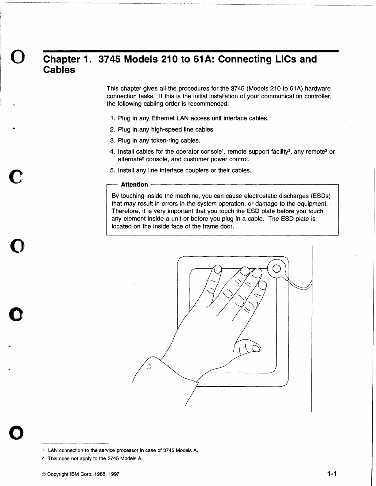
By touching inside the machine, you can cause electrostatic discharges (ESDs)
that may result
Therefore, it is very important that you touch the ESD plate before you touch
any element inside a unit
located on the inside face of the frame door .
in
any high-speed line cables
in
any token-ring cables.
Install cables for the operator console1, remote support facility2, any remote2 or
alternate2 console, and customer power control.
Attention
-------------------------,
in
errors in the system operation, or damage to the equipment. .
or
before you plug in a cable. The ESD plate is
o
o
1
LAN
connection to the service processor
2 This does not apply to the 3745 Models
© Copyright IBM Corp. 1988, 1997
in
case of 3745 Models
A.
A.
1-1
Page 23
-_."
........ _ ....•...• _
......
_---._--_._-_._.....
.
.•.................•.• _ .....••. -.•..•.... --.....•..
---
.. _ .........•......•.
---
..
-.
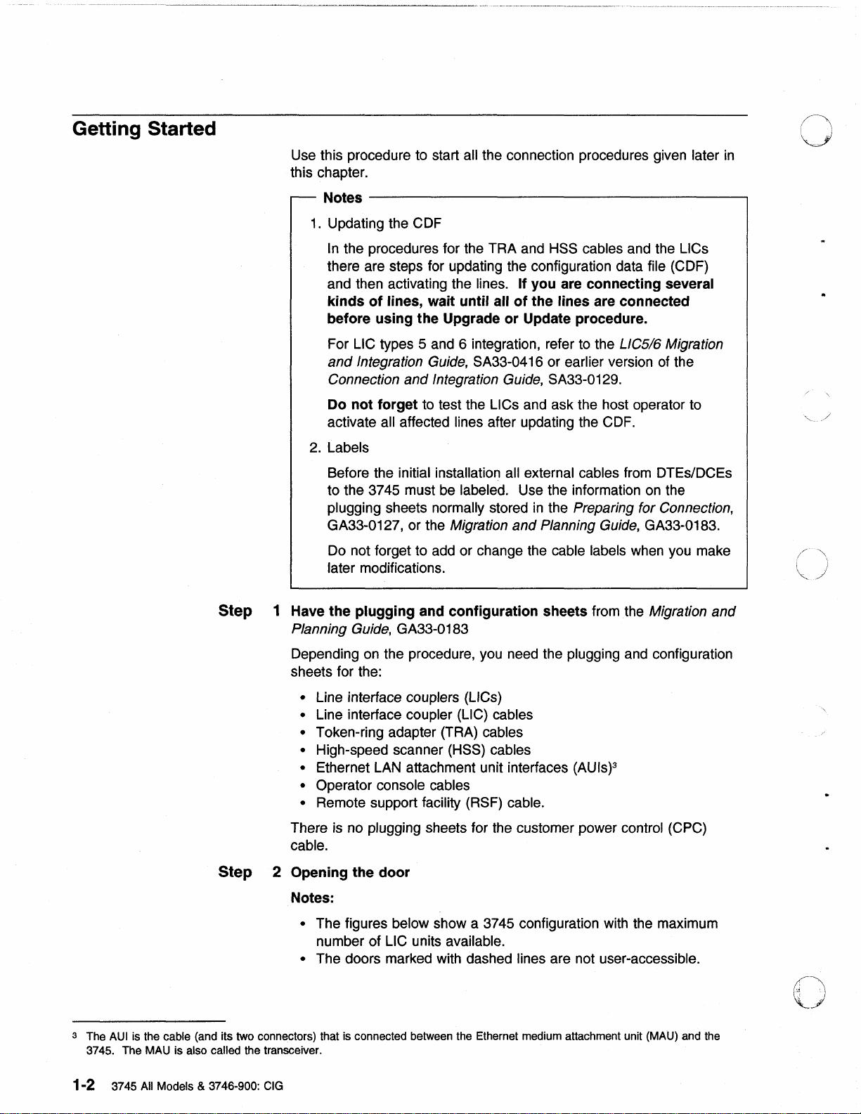
Getting
Started
Use this procedure to start all the connection procedures given later
this chapter.
Notes
1.
----------------------------------------~
Updating the CDF
In
the procedures for the TRA and HSS cables and the LlCs
there are steps for updating the configuration data
and then activating the
kinds
of
lines, wait until all
before using the Upgrade
lines. If you are connecting several
of
the lines are connected
or
Update procedure.
file (CDF)
For LlC types 5 and 6 integration, refer to the LlCSI6 Migration
and
Integration Guide, SA33-0416 or earlier version of the
Connection
Do
not
activate
2.
Labels
and
Integration Guide, SA33-0129.
forget to test the LlCs and ask the host operator to
all affected lines after updating the CDF.
Before the initial installation all external cables from DTEs/DCEs
to the 3745 must be labeled. Use the information on the
plugging sheets normally stored
GA33-0127, or the Migration
in
the Preparing for Connection,
and
Planning Guide, GA33-0183.
()
in
Do not forget to add or change the cable labels when you make
later modifications. i
Step 1 Have the plugging and configuration sheets from the Migration
Planning Guide, GA33-0183
Depending on the procedure, you need the
plugging and configuration
sheets for the:
• Line interface couplers (LlCs)
• Line interface coupler (LlC) cables
Token-ring adapter (TRA) cables
•
High-speed scanner (HSS) cables
•
•
Ethernet LAN attachment unit interfaces (AUls)3
Operator console cables
•
•
Remote support facility (RSF) cable.
There is no plugging sheets for the customer power control (CPC)
cable.
Step 2 Opening the door
Notes:
• The figures below show a 3745 configuration with the maximum
number of
The doors marked with dashed lines are not user-accessible.
•
LlC units available.
/.
~
and
3 The AUI is the cable (and its two connectors) that is connected between the Ethernet medium attachment unit (MAU) and the
3745. The MAU is also called the transceiver.
1-2 3745 All Models & 3746-900: CIG
Page 24
0
•
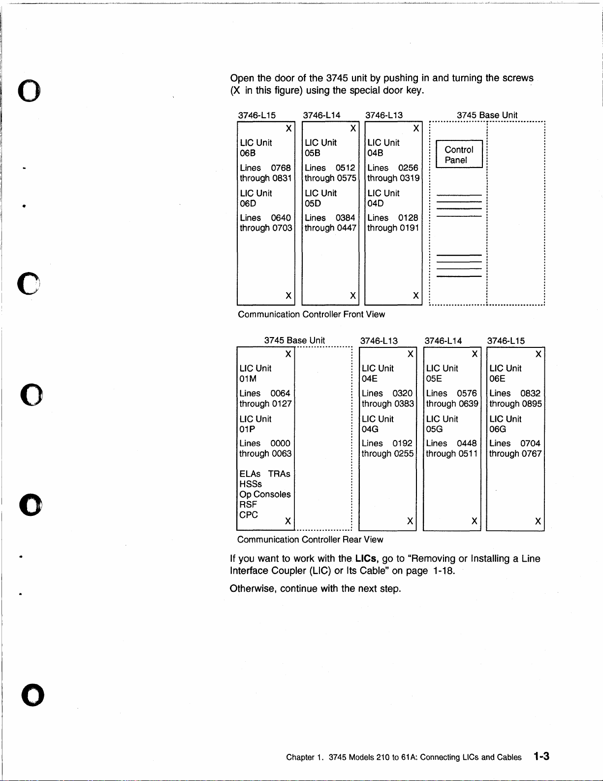
Open the door of the 3745 unit by pushing
(X
in
this figure) using the special door key.
3746-L
15
LlC Unit LlC Unit LlC Unit
068
Lines
through
LlC Unit LlC Unit LlC Unit
060
Lines 0640 Lines
through 0703 through 0447 through
0768 Lines
0831
3746-L
14
X
05B 048
0512
through 0575 through 0319
050
0384 Lines 0128
3746-L 13
X X
Lines
040
0256
0191
in
and turning the screws
3745 Base Unit
......................................
.
o
o
o
X X X
Communication Controller Front View
3745 Base Unit 3746-L13 3746-L 14 3746-L
..
_-_
............
.
X X X X
LlC Unit
01M
Lines 0064
through 0127
LlC Unit
01P
Lines 0000
through 0063
ELAs TRAs
HSSs
Op Consoles
RSF
CPC
L..--
___
Communication Controller Rear View
If you want to work with
I nterface Coupler (Lie) or Its Cable"
X
.........................
LlC Unit
04E
Lines 0320
through 0383
LlC Unit
04G
Lines 0192
through 0255
.
the.
Lies, go to "Removing or I nstalling a Line
X
on
page 1-18.
.
0511
X
,
15
LlC Unit
06E
LlC Unit
06G
Lines 0704
through 0767
.......................................
LlC Unit
05E
Lines 0576 Lines 0832
through 0639 through 0895
LlC Unit
05G
Lines 0448
through
X
o
Otherwise, continue with the next step.
Chapter 1. 3745 Models 210 to
61
A:
Connecting
L1Cs
and Cables 1-3
Page 25
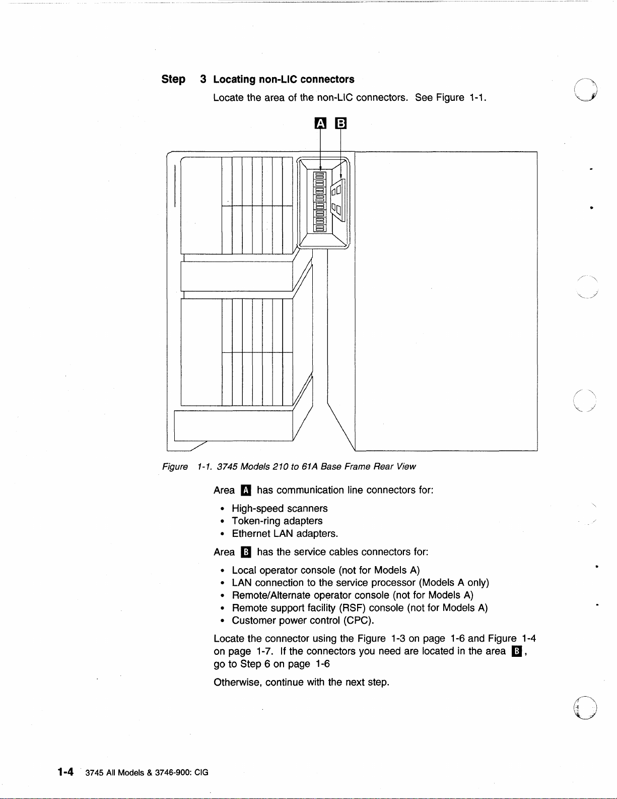
Step 3
Locating
Locate the area of the non-LiC connectors. See Figure 1-1.
non-Lie
connectors
-
-
•
Figure
1-1.
3745 Models
Area m has communication line connectors for:
• High-speed scanners
• Token-ring adapters
• Ethernet LAN adapters.
iii has the service cables connectors for:
Area
• Local operator console (not for Models
• LAN connection to the service processor (Models A only)
•
Remote/Alternate operator console (not for Models
• Remote support facility (RSF) console (not for Models
• Customer power control (CPC).
Locate the connector using the Figure 1-3
on page 1-7.
go to Step 6
Otherwise, continue with the next step.
210
to 61A Base Frame Rear View
A)
on
page 1-6 and Figure 1-4
If the connectors you need are located
on
page 1-6
A)
A)
in
the area iii,
o
1-4 3745 All Models & 3746-900: CIG
Page 26
o
--~~~-
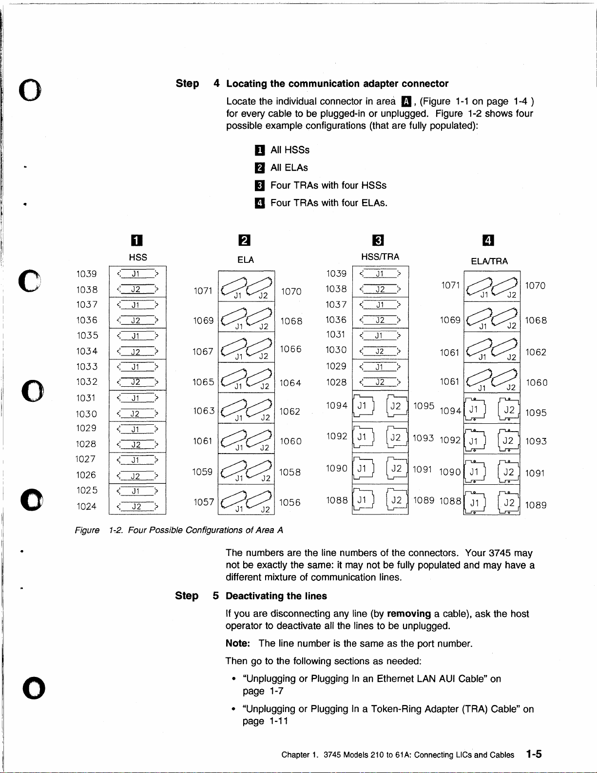
Step 4 Locating the communication adapter connector
-----.--
....
-,
..
-.---.--~---,~~~--
Locate the individual connector
for every
possible
cable to be plugged-in or unplugged. Figure 1-2 shows four
example configurations (that are fully populated):
in
area
m,
D All HSSs
fJ
All ELAs
II
Four TRAs with four HSSs
II
Four TRAs with four ELAs.
(Figure
1-1
on page 1-4 )
C
0
0
1039
1038
1037
1036
1035
1034
1033
1032
1031
1030
1029
1028
1027
1026
1025
1024
c
c
<
c
<
<
c
<
c
<
c:
<,
<:
<
<:
c
,
,
o
HSS
J1
J2
J1
J2
J1
J2
J1
J2
J1
J2
J1
J2
J1
J2
J1
J2
::>
,
?
>
>
?
>
>
>
>
::>
>
>
,
?
::>
I:>
,
:>
ELA
1071
c?C3?
1069
c?,cs?
1067
c?,c;?
1065
aa
1063
c?,~
1061
C?a
1059
C?a
1057
c?c:?z
1070
1068
1066
1064
1062
1060
1058
1056
1039
1038
1037
1036
1031
1030
1029
1028
1094
1092
1090
1088
m
HSSffRA
<
J1
<
J2
<
J1
J2
<:
J1
<:
<
J2
<,
J1
J2
<:
::>
,
;,
?
:>
:>
:>
:>
:>
1095
1093
1091
1089
EI
ELAfTRA
1071
aa
1069
C?a
1061
C?C?Z
1061
C?C:?Z
1094
1092
1090
1088
1070
1068
1062
1060
1095
1093
1091
1089
o
Figure
1-:2.
Four Possible Configurations
Step 5 Deactivating the lines
of
Area A
The numbers are the line numbers of the connectors. Your 3745 may
not be
different mixture of communication
If
operator to deactivate
Note: The line number
Then go to the
exactly the same: it may not be fully populated and may have a
lines.
you are disconnecting any line (by removing a cable), ask the host
all the lines to be unplugged.
is
the same as the port number.
following sections as needed:
• "Unplugging or Plugging
page 1-7
• "Unplugging or Plugging
1-11
page
Chapter
1.
In
an
Ethernet LAN AUI Cable" on
In
a Token-Ring Adapter (TRA) Cable" on
3745 Models 210 to 61A: Connecting LlCs and Cables 1-5
Page 27
•
~~~~lu1~~i~.9
or
Plugging
In
a High-Speed Scanner
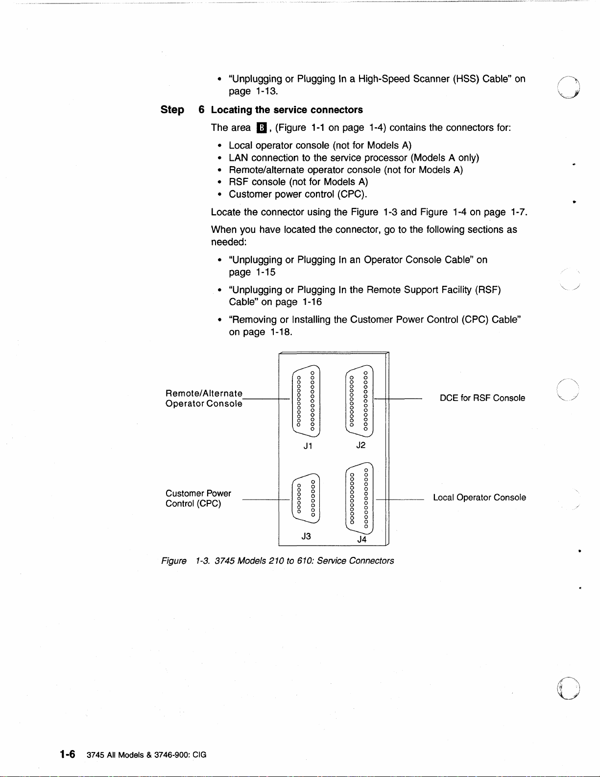
Step 6 Locating the service connectors
(HSS)
Cable"
on
0
The area
• Local operator console (not for Models
• LAN connection to the service processor (Models A only)
•
Remote/alternate operator console (not for Models
• RSF console (not for Models
• Customer power control (CPC).
Locate the connector using the Figure 1-3 and Figure 1-4
When you have located the connector, go to the
needed:
• "Unplugging or Plugging
page 1-15
• "Unplugging or Plugging
Cable"
• "Removing or Installing the Customer Power Control (CPC) Cable"
on
Remote/Alternate
Operator
Console
II,
(Figure
on
page 1-16
page 1-18.
1-1
on
page 1-4) contains the connectors for:
A)
In
an
In
the Remote Support Facility (RSF)
0
0 0 0 0
0
0
0
0
0
0
0
0
0
0
0
0
0 0
0
0
0
0
0
0
0
0
0 0
0
0
0
0
0
0
0
0
0
0
A)
A)
following sections as
Operator Console Cable"
0
0
0
0
0
0
0
0
0
0
0
DCE for RSF Console
on
page 1-7.
on
~
(
..
~
...
~
Customer Power
Control (CPC)
1-3.
Figure
3745 Models 210 to 610: Service Connectors
J1
J3
J2
0 0
0
0
0
0
0
0
0
0
0
0
0
J4
0
0
0
0
0
0
0
0
0
0
0
0
Local Operator Console
1-6 3745 All Models & 3746-900: CIG
Page 28
o
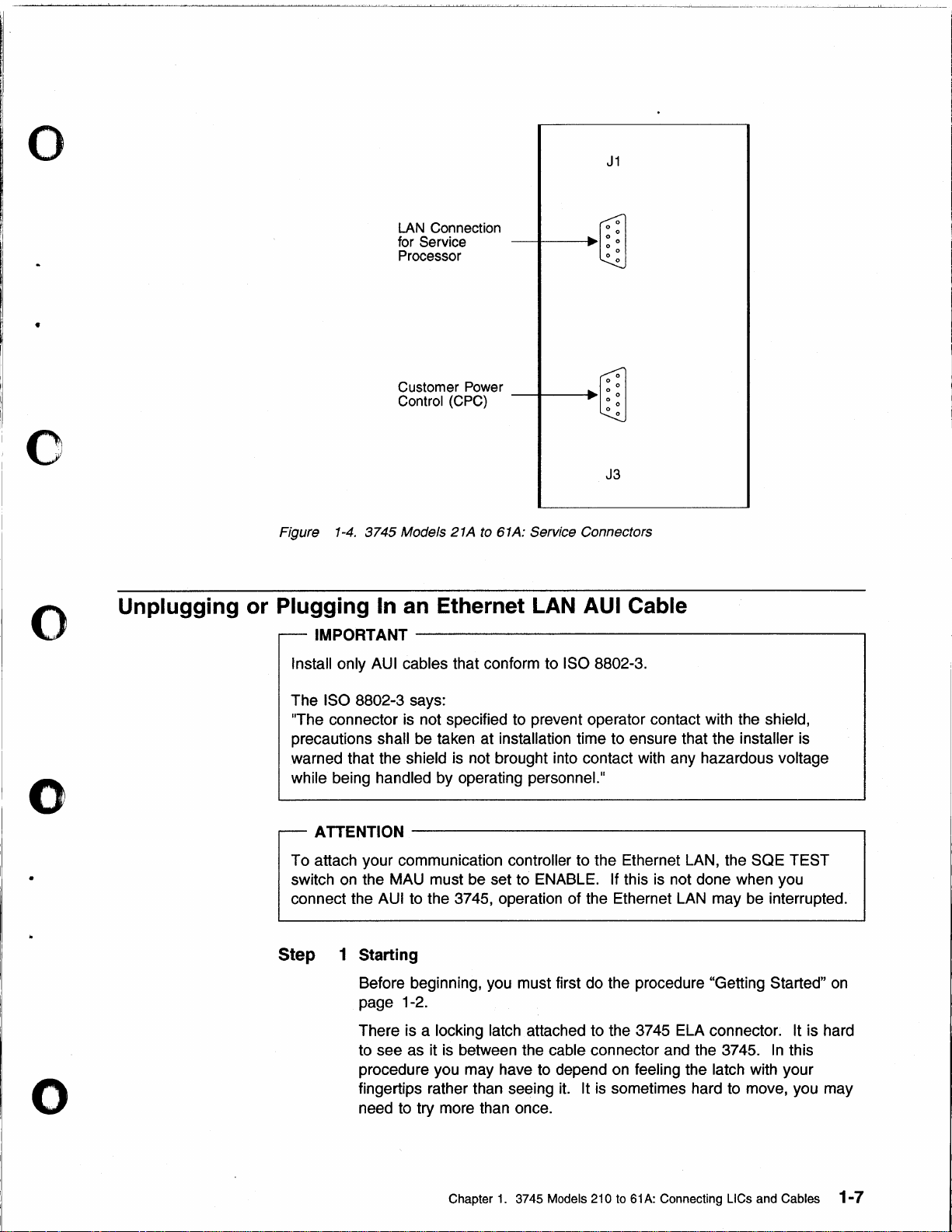
J1
•
o
o
LAN Connection
Figure
1-4.
for Service
Processor
Customer Power •
Control (CPC)
3745
Models 21A to 61A: Service Connectors
--f----I~~I~
--f----I~~I~
Unplugging or Plugging In an Ethernet
IMPORTANT----------------------------------------~
Install only AUI cables that conform to ISO 8802-3.
LAN
.r:T
r:T
J3
AUI Cable
o
o
The ISO 8802-3 says:
IThe connector is not specified to prevent operator contact with the
precautions shall be taken at installation time to ensure that the installer is
warned that the
being handled by operating personneL
while
ATTENTION
To attach your communication controller to the Ethernet LAN, the SQE TEST
switch
connect the
Step 1 Starting
on
Before beginning, you must first do the procedure "Getting Started"
page 1-2.
There is a
to see as it is between the
procedure you may have to depend
fingertips rather than seeing
need to try more than once.
shield is not brought into contact with any hazardous voltage
II
-----------------------------------------------,
the MAU must be set to ENABLE. If this is not done when you
AUI to the 3745, operation of the Ethernet
locking latch attached to the 3745 ELA connector. It is hard
cable connector and the 3745.
on
it.
It is sometimes hard to move, you may
LAN
may
feeling the latch with your
shield,
be
interrupted.
In
this
on
Chapter
1.
3745 Models 210
to
61A: Connecting
L1Cs
and Cables 1-7
Page 29
3745
o
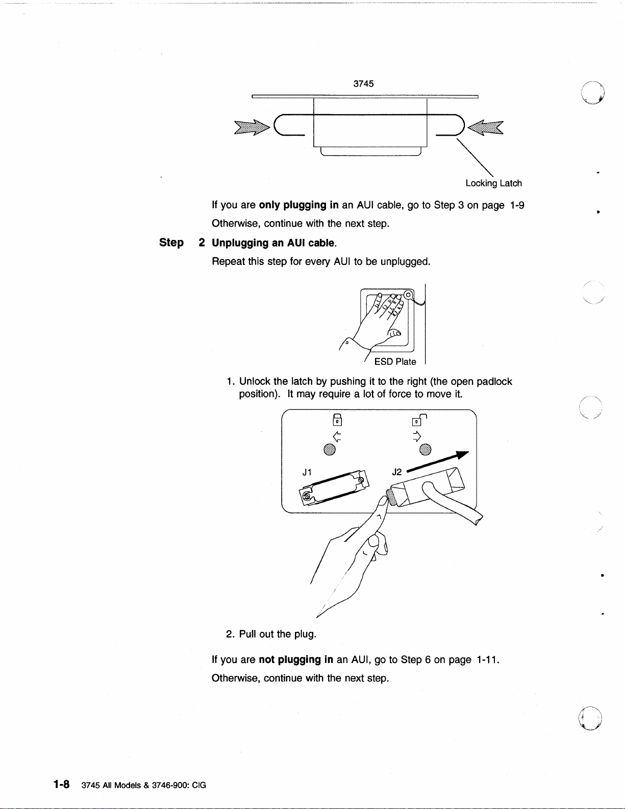
Locking Latch
If you are only plugging in
Otherwise, continue with the next step.
Step 2 Unplugging
Repeat this step for every
1.
Unlock the latch by pushing it
position). It may require a lot of force to move
an
AUI
cable.
an
AUI cable, go to Step 3
AUI
to be unplugged.
to
the right (the open padlock
it.
on
page 1-9
•
1-8 3745 All Models & 3746-900: CIG
2. Pull out the plug.
If
you are not plugging in
Otherwise, continue with the next step.
an
AUI, go to Step 6
on
page 1-11.
o
Page 30

o
Step 3 Plugging
Repeat this step for every
Note: Make sure that all the cables are correctly labeled at both ends
before doing this step.
in
an AUI cable
AUI
to be plugged in.
o
o
1. Locate a
2. Slide the latch to the right (the open padlock position).
cable with a label. Find the port that matches the cable.
o
o
3.
Hold the cable connector so that its longest side
Chapter
1.
3745 Models 210 to 61A: Connecting LlCs and Cables 1-9
is
downward.
Page 31

4. Push the plug strongly into the port connector.
t?J
¢
@)
5.
Push the locking latch to the left
position). It may require a lot of force to move
crl'
=>
@D
to
lock it (the closed padlock
o
it.
1-1
0 3745
Step 4 Routing cable
All
Models & 3746-900: CIG
6.
To check that the cable is locked
connector from side-to-side while trying to pull it out of the 3745
Do
ELA connector.
You may use the magnetic clamp that came with your Ethernet adapter
to secure and separate the
machine becomes too crowded with
not jerk
AUI cables from the other cables if your
in
on
the cable.
cables.
place, move the cable
1t
o
Page 32

o
Magnetic Cable Clamp
Step 5 Activating the lines
Extra Clamps are Available on Request.
Please Contact your
The Part Number
IBM Service Representative.
is
26F1775.
Ask the host operator to activate any lines plugged
o Notes:
a.
The line number
b.
If you have installed a link-attached 3745, make sure that the link
IPL
Step 6 You have finished this procedure
Close and lock the door using the special door key.
o
o
•
Unplugging or Plugging
If you have a 3745 Model A without a 3746-900 attached
Do not use this procedure to make changes to the cable that connects the 3745
to the token-ring LAN used by the service processor. These are
representative tasks.
Step 1 Starting
If you have not done the procedure "Getting Started"
so now.
If you are only plugging
Otherwise, continue with the next step.
In
in.
is
the same as the port number.
port cables are connected before attempting
an I PL.
a Token-Ring Adapter (TRA) Cable
---------.
IBM service
on
page 1-2, do
in
TRA cable, go to Step 3 on page 1-12
o
Chapter
1.
3745 Models
21 0 to
61
A:
Connecting LlCs and Cables
1-11
Page 33

Step 2
Unplugging a TRA
Repeat this step for every TRA cable to
1.
Remove the cable by squeezing the levers and pulling out the
plug.
2.
Replace the protective cap
cable.
be
unplugged.
on
the cable plug.
o
..
/ -
",
Protective Cap /
If you are
Otherwise, continue with the next step.
Step 3
Step 4 Upgrade CDF
Plugging
Repeat this step for every TRA cable
Note: Make sure that all the cables are correctly labeled at both ends
before doing this step.
a.
b.
c.
d.
You must perform the Upgrade procedure
CDF" on page 5-7. You can either do it now and continue with the next
step or
not
in a TRA
Refer to the figure of the Step
Locate the cable with a label that matches its port number.
Remove the protective cap from the cable plug.
Hold this plug with the levers
and push the plug strongly into the port.
later when you have finished all your connection procedures.
plugging
cable.
in
a TRA cable, go to Step 6
to
be
plugged
2.
on
the sides, squeeze both levers,
in
"Upgrading or Updating
on
in.
page 1-13.
•
1-12 3745
All
Models & 3746-900: CIG
o
Page 34

0
Step
Activating the lines
5
Ask the host operator to activate any lines that were plugged in.
o
o
Note:
Step
Unplugging or Plugging
Step 1 Starting
Step
You have finished this procedure
6
If you have no other connection procedures to do, close and lock the
door using the special door key.
If you have not done the procedure "Getting Started"
so now.
If you are only plugging
Otherwise, continue with the next step.
2 Unplugging
Remove the cable by squeezing the levers and
The line number
In
a High-Speed Scanner (HSS) Cable
an
HSS cable
is
the same as the port number.
in
HSS cables, go to Step 3
pulling out the plug.
on
page 1-2, do
on
page 1-14
o
o
) ]
: ;
Repeat this step for every HSS cable to be unplugged.
If you are not plugging
Otherwise, continue with the next step.
in
an
HSS cable, go to Step 4 on page 1-14
) )
Chapter
1.
3745 Models 210 to 61A: Connecting
L1Cs
and Cables 1-13
Page 35

Step
3 Plugging
Repeat this step for every HSS cable
Note:
a.
b.
c.
in
an HSS cable.
• Make sure that all the cables are correctly labeled at both
ends before doing this step.
• If you connect the HSS to a DTE equipment (such as IBM
2210
side of the
DCE side to the router.
Refer to the figure of the Step 2
Locate the cable with a label that matches its port number.
Take the plug of one cable, squeeze the side levers, and push the
plug strongly into the corresponding port
Step 4 Upgrade CDF
You must perform the Upgrade procedure
CDF"
on
page 5-7. You can either do it now and continue with the next
step or
later when you have finished all your connection procedures.
to
be plugged
router), for allowing RLSD signal propagation, the DCE
cable must be connected to the HSS and the
on
page 1-13.
in
in
"Upgrading or Updating
in.
your unit.
0
/~
.",
\c...
Step
Step
Activating the lines
5
Ask the host operator
Notes:
a.
The line number is the same as the port number.
b.
If you have installed a link-attached 3745, make sure that the link
port cables are connected before attempting
IPL
You have finished this procedure
6
If you have no other connection procedures to do, close and lock the
door using the
special door key.
to
activate any lines plugged
in.
an
IPL.
(/
\",
'\
;J
/'
1-14 3745 All Models & 3746-900: CIG
Page 36

o
Unplugging or Plugging In an Operator Console Cable
Note: This procedure applies to both local and alternate/remote cables connected
J1
and J4 (see Figure 1-3
to
on
page 1-6).
o
o
Attention
This procedure does not apply for Models
Step
Step
1 Starting
2 Unplugging
-------------------------,
If you have not done the procedure "Getting Started"
so now.
Ask the host operator to
you are only plugging
If
page 1-16.
Otherwise, continue with the next step.
an
operator console cable
a.
Unfasten the ground cable clamp. This cable clamp is fixed
bottom of the frame
log off
in
in
one of the three holes.
A.
on
page 1-2, do
at
the application console.
an
operator console cable, go to Step 3 on
on
the
o
o
b.
Remove the cable by squeezing the levers and pulling out the plug.
Chapter
1.
3745 Models 210 to 61A: Connecting LlCs and Cables
1-15
Page 37

Repeat this step for every operator console cable to be unplugged.
you are only unplugging
If
an
operator console cable, go to Step
5.
o
Step 3 Plugging
a.
b.
c.
d.
Repeat this step for every operator
Step 4 Host log
The operator may now log
in
an
operator console cable
Refer to the figures of the Step 2
Find the cable with a label that matches the connector.
Fasten the ground cable to the frame with the cable clamp. This
cable clamp
holes.
Note: The ground cable clamp serves
radio frequency interference that might be caused by the operating
machine. Proper
meet FCC requirements, and to conduct
(ESDs) to ground.
Hold the plug of the cable with the green side lever upward,
squeeze both side
connector.
on
is
fixed
on
the bottom of the frame
installation of the cable clamp
levers, and push the plug strongly into the
on
to the application console.
Step 5 You have finished this procedure
If you have no other connection procedures to do, close the door using
the
special door key.
on
page 1-15.
in
one of the three
to
reduce the possibility of
is
necessary to
electrostatic discharges
console cable to be plugged in.
Unplugging or Plugging In the Remote Support Facility (RSF) Cable
See Figure 1-3
Attention
This procedure does not apply for Models
Step 1 Starting
on
page 1-6 to locate this cable.
-----------------------.....,
A.
If you have not done the procedure "Getting Started"
so now.
If you are only plugging
Otherwise, continue with the next step.
in
the RSF cable, go to Step 3
on
page 1-2, do
on
page 1-17.
1-16 3745 All Models & 3746-900: CIG
Page 38

o
•
o
Step 2 Unplugging the DCE cable for RSF
a.
Unfasten the ground cable clamp. This cable clamp is fixed
bottom of the frame
b.
Remove the cable by squeezing the levers and pulling out the plug.
in
one of the three holes .
on
the
o
o
you are only unplugging the RSF cable, go to Step 4
If
Step 3 Plugging in the DCE cable for RSF
a.
Refer to the figures of the Step
b.
Find the cable with a label that matches the connector.
c.
Fasten the ground cable to the frame with the cable clamp. This
clamp is fixed
cable
holes.
Note: The cable clamp serves to reduce the possibility of radio
frequency interference that might be caused by the operating
machine.
meet
(ESDs) to ground.
Proper installation of the cable clamp is necessary to
FCC requirements, and to conduct electrostatic discharges
on
the bottom of the frame
2.
on
page 1-18.
in
one of the three
o
Hold the plug of the cable with the green side lever upward,
d.
squeeze both side
connector.
Chapter
levers, and push the plug strongly into the port
1.
3745 Models 210 to
61
A:
Connecting LlCs and Cables 1-17
Page 39

Step 4 You have finished this procedure
If you have no other connection procedures to do, close and lock the
door using the special door key.
Removing or Installing the Customer Power Control (CPC) Cable
Note: The CPC cable and connector are not provided by IBM, and, therefore, are
not shown here; neither are given the details of securing the CPC cable
Step 1 Starting
If you have not done the procedure "Getting Started" on page 1-2, do
so now.
in
place.
·.:
I.
,
0
If you are only plugging in the CPC cable, go to Step
Otherwise, continue with the next step.
Step 2 Unplugging the
Remove CPC cable from CPC connector. See Figure 1-3
or
Figure 1-4 on page 1-7.
If you are not plugging
Step 3 Plugging
in
the
CPC
CPC
cable
in
the CPC cable, go to Step 4.
cable
3.
on
page 1-6
,/
1.
Find the cable with a label that matches the connector.
Install the cable into the CPC connector.
2.
Step 4 You have finished this procedure
If you have no other connection procedures to do, close and lock the
door using the special door key.
Removing or Installing a Line Interface Coupler (LIC) or Its Cable
For
L1C
types 5 and 6, refer to the LICSI6 Migration
SA33-0416
LIC Slots: Regardless
line numbers are
1,3,
and 4.
1-18 3745 All Models & 3746-900: CIG
or
earlier version
allocated for each
of
of
the number
the Connection
of
ports (lines) that are actually used, four
L1C
slot
in
and
Integration Guide,
and
Integration Guide, SA33-0129.
an
LI U 1.
These slots hold
L1C
o
types
Page 40

o
Line Weights: When reconfiguring LlCs, ensure that the total weight of lines
connected to a low-speed scanner is within the scanner maximum capacity. To
A,
calculate them see Appendix
"LSS Characteristics and Line Weights."
Step 1 Starting
If you have not done Steps 1 and 2 of the procedure "Getting Started"
on
page 1-2, do so now.
0
0
Lie
D E F
104 108
100
096
0
p
101
097
0
R
098
2
T
S
099
3
For example,
LIe
in
of the 3745 base frame unit).
105 109 113
102 106 110
103 107
1m
slot H (in the upper half of the upper
Step 2 Locating the
Use the LlU tables
Following are schematic representations of the possible locations of
LlCs and their line numbers within the unit you have opened.
The following tables are for
1 and
Lie
4 Slots
H J K
G
116 120
1m
121
117
118
114
111
115
is the number of port 0 for the
122
119
123
L1U
For LUI2 (LiC types 5 and
Integration Guide,
Integration Guide,
L
124
125
126
127
Lie
slot
on
the inner surface of the open unit door.
an
LlU1
(LiC types
D E F
p
o
R
T
S
1
SA33-0416 or earlier version of the Connection and
SA33-0129.
096 100
DeE
096 100 104
DTE
Lie
3s have only one port but two types of
connectors:
attachment).
6),
refer to the LICSI6 Migration and
104
DeE
1,
3,
and 4).
Lie
3 Slots
H J K L
G
112
108
108
(modem) or DTE (direct
116
112 116
120 124
124
120
o
o
Repeat this step for every
If you are only installing a
If you are only plugging
Otherwise, continue with the next step.
Step 3 Deactivating line
Ask the host operator to deactivate all the lines connected to the LlC
you want
Deactivation of all the lines of the
problems at line adapter restart.
The line number is the same as the
For
There are up to four lines per LlC.
to
Attention
L1C
types
Chapter
work with.
---------------------,
1,
LlC to be inserted or removed.
L1C,
in
a LIC cable, go to Step 8
3,
and
4:
1.
3745 Models 210 to
go to Step 4
L1C
is necessary to prevent
LlC port number.
61
A:
Connecting
on
page 1-20.
L1Cs
on
page 1-22.
and Cables 1-19
Page 41

For LlC types 5 and
6:
LlC1 (4 Ports)
0
Port
Port 1
Port 3
Refer to the LICS/6 Migration
earlier version of the
Step 4 Identifying LlC
Lies
are not labeled. To identify a
LlC3
(2
Ports)
• Use upper port for
attachment.
• Use lower port for direct
attachment.
and
Connection
DeE
Integration Guide, SA33-0416 or
and
Integration Guide, SA33-0129.
Lie,
make a visual inspection.
LlC4 (4 Ports)
•
Lies
4A and
identical, the choice being
made at configuration time.
•
L1C
48
48
are physically
uses port 0 only.
Figure 1-5.
LlC
Types
1,
3,
and
4.
Step 5 Unplugging LlC cable
Repeat this step for every
Unplugging LlC types 1, 3, and 4 Cable
Lie
cable to be removed.
Remove the cable by squeezing
the side levers and pulling out the
plug.
c
1-20 3745 All Models & 3746-900: CIG
Page 42

Unplugging LlC types 5 and 6 Cable
o
o
Step
Refer to the LICSI6 Migration
earlier version of the
you are only unplugging a Lie cable, go to Step 10
If
If you are only plugging in Lie cable without removing Lie, go to Step
8 on page 1-22.
Otherwise,
6 Removing LIC
Repeat this step for every
a.
Turn the knob counterclockwise to unlock the
b.
Remove the Lie by delicately pulling it out.
to remove LlC, continue with the next step.
Connection
and
Integration Guide, SA33-0416 or
and
Lie
to be removed.
Integration Guide, SA33-0129.
on
page 1-25.
Lie.
o
If you have no LlCs to install, go to Step 10
o Otherwise, continue with the next step.
Step 7 Inserting LlC
a.
Ensure that the slot
bundle of
bracket (Do not forget
bracket when finished).
b.
Hold the
knob
c.
Push the Lie into the slot until it clicks.
d.
Turn the knob clockwise to lock the
Lie types 5 and
For
Guide,
Guide,
SA33-0416 or earlier version of the Connection
SA33-0129.
cables for this
LIe
so that the black plastic side
is
pointing toward you.
is
clear. If necessary, carefully remove the
Lie
row from behind the cable retaining
to
replace the cables behind the retaining
6,
refer to the LlCSI6 Migration
Lie
on
page 1-25.
is
on
in
place.
the left and the
and
Integration
and
Integration
o
Chapter
1.
3745 Models 210 to 61A: Connecting
lICs
and Cables 1-21
Page 43

Step 8
Plugging
in
Lie
cable
At initial installation, the following order is recommended:
o 3745 Base or 3746 Expansion Unit.
Start with the Top Row of LlCs and
Work Towards the Bottom:
I
/
~
I
/
"<~
~
~
I
-
./'"
./'"
/"
'
......
:
............
.........
:~::::
....
,.,...
)
)
·~"I..IC
....
Uni~:"
SUH:~
with the
Work"T~~ards
~-"-7
Right:,.~and
the
Left~
••••••••• •
''''''''''A
LlC and
.........
o
.
••••
'"
"''''
Bl
LlC.
Start with the Lower Connector of a LlC and
Work Towards the
Top:
Make sure that all the cables are correctly labeled at both ends before
doing this step.
Repeat this step for every
Lie
cable installed.
./
1-22 3745 All
Models
& 3746-900:
CIG
Page 44

Plugging
In
LlC Type 1, 3, and 4 Cable
o
o
o
Plugging
Refer to the
earlier version of the
In
LlC Types 5 and 6 Cables
LIC516 Migration
and
Connection
1.
Locate the cable with a label
that matches the information
on
the plugging sheet for the
lower port of the
2.
Hold the plug
with the green lever upward,
squeeze both side levers, and
push the plug strongly into
the port.
3.
Plug
in
all lower cables, then
continue with the upper
cables.
Attention
For LlC types 3 and 48,
only one cable must be
connected
Integration Guide, SA33-0416 or
and
Integration Guide, SA33-0129.
LlC.
of
the cable
--------,
o
o
Chapter
1.
3745 Models 210 to 61A: Connecting LlCs and Cables 1-23
Page 45

Step 9 Routing cable
3745 Base Frame /'",
(/
/~(
I:
1[:
~~
Ensure that all the cables are neatly arranged and well secured.
can use magnetic clamps to separate
types of cables.
..... ' .............................
Tiewr\s
For
a drawing of the clamp, see Figure 1-6.
,.
3746-L 1x
and
neatly arrange the different
You
l:)RetainJ
__
~_~~ables
o
Figure
I~
I"
Magnetic Cable Clamp
1-6.
3745 Cable Arrangement
~
rl
/
If
many cables are to be installed,
use the magnetic cable clamps. These
clamps are available
contact your IBM service representative.
The part number
• If you are
the next step.
• If you are
on
request. Please
is
26F1775.
only
only
installing
replacing a LlC cable, go to Step 13
Ii ;
or
replacing a LlC
type
1, 3,
on
or
4,
go to
page 1-25.
c
"\
1-24 3745 All
Models
o
& 3746-900: CIG
Page 46

0
Step
10
Updating the CDF
Go to "Upgrading or Updating CDF"
as instructed. Then:
on
page 5-7 and perform the steps
0
0
Step
Step
Step
• If you are
the next step.
• If you are
Step 13
• If you are
next step.
11
Testing a LlC
Refer to the wrap test (WTT) function
Guide,
NCP must be loaded to
If you have installed more than one LlC or
for each one installed.
Otherwise, continue with the next step.
12
Configuring
Refer to the LICSI6 Migration
earlier version of the Connection
13
Activating
Ask the host operator to activate the line of all newly installed LlC or
L1C
SA33-0097 and perform the automatic wrap test at the
cable.
only
installing
only
installing a new LlC
only
replacing a LlC type 1, 3,
type
1, 3,
or
run
the
LlC 5 and 6 Modems
the
lines
or
replacing a LlC
type
4
in
the Advanced Operations
WTT.
L1C
and
Integration Guide, SA33-0416 or
and
Integration Guide, SA33-0129.
type
1, 3,
or
or
4 cable,
cable, repeat this step
1, 3,
4 cable, go to
go
or
to the
Lie.
4,
go to
level.
0
o
Attention
If one
of
the affected lines was not deactivated at Step 3
page 1-19, you may be forced to re-Ioad the
Step 14 You have finished
Do no more steps. If you have no other connection procedures to do,
close and lock the door using the special door key.
this
procedure
NC
on
P.
Chapter
1.
3745 Models 210 to 61A: Connecting LlCs and Cables 1-25
Page 47

()
1-2,6
3745
All
Models & 3746-900: CIG
Page 48

o
•
Chapter
Cables
2.
3745 Models 130 to 17A: Connecting LICs and
This chapter gives all the procedures for the 3745 (Models 130, 150, 160,170, and
If this
is
17 A) hardware connection task.
communication controller, the following cabling order is recommended:
1.
Plug
in
any Ethernet LAN access unit interface cables
2. Plug
in
any high-speed line cables
the initial installation of your
o
o
o
3. Plug
4.
5.
By touching inside the machine, you can cause electrostatic discharges (ESDs)
that may result
Therefore, it is very important that you touch the
any element inside a unit or plug
inside face of the frame door.
in
any token-ring cables
Install the operator console(s)1, remote support facility2, any remote2 or
alternate2 console, and customer power control cables.
Install any line interface couplers or their cables.
Attention
------------------------,
in
errors
in
the system operation, or damage
ESD plate before you touch
in
a cable. The ESD plate
to
the equipment.
is
located on the
o
1 LAN connection to the service processor
2 This does not apply to the 3745 Model 17
© Copyright IBM Corp. 1988, 1997
in
case of 3745 Model 17
A.
A.
2-1
Page 49

Getting
Started
Use this procedure to start all connection procedures given later
chapter.
in
o
this
Notes
1.
2.
------------------------------------------.
Updating the CDF
I n the procedures for the TRA
there are steps for updating the configuration data
and then activating the
kinds
of
lines, wait until all
lines. If you are connecting several
before using the Upgrade
For LlC type 5 and 6 integration, refer to the LICS/6 Migration
and
Integration Guide, SA33-0416 or earlier version of the
Connection
Do
not
activate
Labels
Before the initial installation all external cables from DTEs/DCEs
to the 3745 must be
plugging sheets normally stored
GA33-0140, or the Migration
Do not forget to add or change the
modifications.
and
Integration Guide, SA33-0129.
forget to test the LICs and ask to host operator to
all affected lines after updating the CDF.
labeled. Use the information on the
'and
HSS cables and the LlCs
of
the lines are connected
or
Update procedure.
in
the Preparing for Connection,
and
Planning Guide, GA33-0183.
cable labels when you make
file (CDF)
(
I
~
Step 1 Have the plugging' and configuration sheets from the Migration
Planning Guide, GA33-0183.
Depending on the procedure(s), you need the
configuration sheets for the:
• Line interface couplers (LlCs)
• Line interface coupler (LlC) cables
•
Token-ring adapter (TRA) cables
High-speed scanner (HSS) cables
•
Ethernet LAN attachment unit interfaces (AUls)3
•
Operator console cables
•
•
Remote support facility (RSF) cable.
There is no
cable.
Step 2 Opening the
Open the rear door of the 3745 unit by pushing
screws using the
If you want to work with the Lies, go to "Removing or Installing a Line
Interface Coupler (LlC) or Its Cable" on page 2-13.
plugging sheets for the customer power control (CPC)
door
special door key.
plugging and
in
and turning the
and
3 The
AUI
is the cable (and its two connectors) that is connected between the Ethernet medium attachment unit (MAU) and the
3745. The MAU is also called the transceiver.
2-2 3745
All
Models & 3746-900: CIG
Page 50

Otherwise, continue with the next step.
o
o
Operator console and
/
RSF cable connector
area
Step 3 Locating communication line and service connectors
Locate the area of non-LiC connectors, that is communication line and
service connectors.
See Figure 2-1.
goo
88
88
t..
o
o
o
Token-ring
adapter connector
area
/'
/
CPC cable
connector
Figure 2-1. Non-LIC Connector Location
You have only the customer power control (CPC) connector
available for user access.
You do not have connectors for the operator
remote support facility
Installing
service representative task.
When you have
needed:
• "Unplugging or Plugging
• "Unplugging or Plugging
• "Removing or Installing the Customer Power Control (CPC) Cable"
For communication
"
High-speed scanner or
Ethernet
connector area
If you have a 3745
or changing the service processor or cable is an IBM
located the connector(s), go to the following sections as
page 2-9
Cable"
on page 2-12.
on page 2-11
lines, continue with the next step.
LAN
attachment
Model17A
(RSF) console.
In
In
-------------,
console and for the
an Operator Console Cable" on
the Remote Support Facility (RSF)
Chapter
2.
3745 Models 130
to
17A: Connecting LlCs and Cables 2-3
Page 51

Step 4 Deactivating lines
If you are disconnecting any line (by removing a cable), ask the host
operator to deactivate
Note: The line number is the same as the port number.
Then go to the
Unplugging or Plugging
IMPORTANT----------------------------------------~
Install only AUI cables that conform to ISO 8802-3.
The ISO 8802-3 says:
"The connector is not specified to prevent operator contact with the shield,
precautions shall be taken at installation time to ensure that the installer is
warned that the
while being handled by operating personnel."
all the lines to be unplugged.
following sections as needed:
• "Unplugging or Plugging
• "Unplugging
page 2-7
• "Unplugging or Plugging
page 2-8.
In
an
shield is not brought into contact with any hazardous voltage
or Plugging
Ethernet
In
an
Ethernet
In
a Token-Ring Adapter (TRA) Cable"
In
a High-Speed Scanner (HSS) Cable"
LAN
AUI
LAN
Cable
AUI
Cable"
o
on
on
ATTENTION
To attach your controller to the Ethernet LAN, the SQE TEST switch
MAU must be set to ENABLE.
the 3745, operation of the Ethernet LAN may be interrupted.
----------------------------------------,
If this
is
not done when you connect the AUI to
Step 1 Starting
Before beginning, you must first do the procedure "Getting Started" on /
page 2-2. j
There is a locking latch attached
to see as it is between the
procedure you may have to depend
fingertips rather than seeing
need to try more than once.
3745
If you are only plugging
Otherwise continue with the next step.
in
to
the 3745 ELA connector. It
cable connector and the 3745.
on
feeling the latch with your
it.
It
is
sometimes hard to move, you may
Locking Latch
AUI cable(s), go to Step 3
on
on
In
page
the
this
2-:-6.
is
hard
'\
, "
0
··•·.·
2-4 3745
All
Models & 3746-900: CIG
Page 52

o
Step 2 Unplugging an AUI cable
Repeat this step for every
1.
Locate the port.
{
AUI
cable to be unplugged.
o
o
o
r\
1
®
1061~
~
2
®
\\
1060 1062
~
2.
Unlock the cable by sliding the latch upwards and to the left (the
padlock position). It may require a lot of force
open
~1
tID
r\-
106~
~2
tID
~
to
move it.
o
3.
Pull out the plug.
you are going to plug
If
Otherwise, go to
Step 5
Chapter 2. 3745 Models 130
in
a new cable, continue with the next step.
on
page 2-7.
to
17A: Connecting LlCs and Cables 2-5
Page 53

Step 3 Plugging
in
an AUI cable
Repeat this step for every cable to be plugged
1.
Locate the cable by the port number written
2.
Touch the electrostatic discharge plate.
3.
Locate the port.
~
1
®
1061~
~
2
®~.
1060 1062
~
~1
@)~-
1063~
~2
@)
~
in.
on
the label.
o
/
'\
4.
Plug
in
the new Ethernet cable and lock it
down and to the right (the closed padlock position).
r:
"\
in
place by sliding the latch
/---"'.
2-6
·3745
All
Models & 3746-900:
o
CIG
Page 54

o
Step 4 Activating the line(s)
Ask the host operator to activate the line(s).
Note: If you have installed a link-attached 3745, make sure that the
link IPL port cables are connected before attempting an IPL.
Step 5 You have finished this task
Close and lock the door using the special door key.
•
o
o
Unplugging or Plugging In a Token-Ring Adapter (TRA) Cable
If you have a 3745 Model A without a 3746-900 attached
Do not use this procedure to make changes to the cable that connects the 3745
to the token-ring LAN used by the service processor. These are
representative tasks.
Step 1 Starting
Before beginning you must first do the procedure "Getting Started" on
page 2-2.
If you are only plugging in TRA cable(s), go to Step 3
Otherwise continue with the next step.
Step 2 Unplugging TRA cable(s)
Repeat this step for every TRA cable to be unplugged.
--------,
IBM service
on
page 2-8.
o
o
a.
Remove the cable by squeezing the levers and pulling out the plug.
b.
Replace the protective cap on the cable plug.
If
you are going to plug
Otherwise, go
to
Step 4
Chapter 2. 3745 Models 130 to 17A: Connecting LlCs and Cables 2-7
in
a new cable, continue with the next step.
on
page 2-8.
Page 55

Step 3
Plugging in TRA c8ble(s)
Repeat this step for every TRA cable
Note: Make sure that all the cables are correctly labeled at both ends
dOing
before
a.
Refer to the figures of the Step 2
b.
Locate the cable by the port number written
c.
Touch the electrostatic discharge plate.
this step.
to
be plugged
on
page
2:-7.
on
in.
the label.
0
Step
Step
4
Upgrade CDF
You must perform the Upgrade procedure
CDF"
step or
5 Activating lines
Ask the host operator to activate any lines that were plugged
Note: The line number is the same as the port number.
Step 6 You have finished this procedure
If you have no other connection procedures to do, close and lock the
door using the
Unplugging or Plugging
Step 1 Starting
Before beginning you must first do the procedure "Getting Started"
page 2-2.
d. Remove the protective cap from the cable plug.
e.
Plug
in
the new TRA cable by squeezing the levers and pushing the
cable into place until it clicks.
in
"Upgrading or Updating
on
page 5-7. You can either do it now and continue with the next
later when you have finished all your the connection procedures.
special door key.
In
a High-Speed Scanner (HSS) Cable
in.
on
•
- -
/
'\
"-
~
Step 2 Unplugging an HSS cable
2-8 3745 All Models & 3746-900: CIG
If you are only plugging
Otherwise continue with the next step.
Remove the cable by squeezing the levers and pulling out the plug.
Repeat this step for every HSS cable to be unplugged.
If you are not plugging
Otherwise, continue with the next step.
in
HSS cables, go to Step 3
J1
J2
DO
1029 1028
in
an
HSS cable, go to Step 4
on
page 2-9.
J1
J2
DO
1031
1030
on
page 2-9.
Page 56

Step 3
Plugging in an
HSScable
0
•
0
0
Repeat this step for every HSS cable to be plugged
Note:
• Make sure that
ends before doing this step.
• If you connect the HSS to a DTE equipment (such as IBM
2210 router), for allowing RLSD signal propagation, the DCE
a.
Refer to the figure of the Step 2
b.
Locate the cable by the port number written
c.
Plug in the new HSS cable by squeezing the levers and pushing the
cable into place until it clicks.
Step 4 Update CDF
You must perform the Update procedure
CDF" on page 5-7. You can either do it now and continue with the next
Step
Step 6
5
step or
Activating the line
Ask the host operator to activate any lines that were plugged in.
Note:
link I
You have finished
later when you have finished all your connection procedures.
If you have installed a link-attached 3745, make sure that the
PL
port cables are connected before attempting
all
the cables are correctly labeled at both
side of the
DCE side to the router .
cable must be connected to the HSS and the
this
task
on
page 2-8.
in
in.
on
the label.
"Upgrading or Updating
an I PL.
o
o
Unplugging
Close and lock the door using the special door key.
or
Plugging In an Operator Console Cable
Attention
This procedure does not apply for Model 17
Step 1 Starting
-------------------------,
A.
Before beginning you must first do the procedure "Getting Started" on
2-2.
page
If you are
Otherwise continue with the next step.
only
inserting a console cable, go to Step 3
on
page 2-10.
Chapter 2. 3745 Models 130 to 17A: Connecting
L1Cs
and Cables 2-9
Page 57

Step 2 Unplugging cable{s)
a.
Ask the operator of the appropriate console to log off.
b.
Touch the electrostatic discharge plate.
c.
Unfasten the cable ground clamp. The cable clamp is fixed at the
bottom left of the frame by one of the three wing nuts.
d.
Unplug the cable by squeezing the levers
the plug and
pulling it out.
on
the top and bottom of
RSF
REMOTE LOCAL
o
,
Step 3 Plugging in cable{s)
2·1 0 3745 All Models & 3746-900: CIG
If you are going to plug
to
Otherwise, go
a.
Refer to the figures of the Step
b.
Locate the cable by the label
c.
Touch the electrostatic discharge plate.
d. Plug
e.
in
the console cable.
Fasten the cable ground
cable clamp is fixed at the bottom left of the frame by one of the
three wing nuts.
Note: The cable clamp serves to reduce the possibility of radio
frequency interference that might be caused by the operating
machine. Proper installation of the cable clamp is necessary to
meet FCC requirements and to conduct electrostatic discharges to
ground.
Step 4
in
a new cable, continue with the next step.
on
page 2-11.
2.
on
the cable.
to
the frame with the
cabJe
clamp. The
0'1",
•
,i:
Page 58

o
Step 4 You have finished this task
Close and lock the door using the special door key.
o
o
Unplugging or Plugging In
Attention
This procedure does not apply for Model 17
Step 1 Starting
Before beginning you must first do the procedure "Getting Started" on
page 2-2.
If you are only inserting a console cable, go to Step 3 on page 2-12.
Otherwise continue with the next step.
Step 2 Unplugging the
a.
Ask the operator of the appropriate console
b.
Touch the electrostatic discharge plate.
c.
Unfasten the cable ground clamp. The cable clamp is fixed at the
bottom left of the frame by one of the three wing nuts.
the
Remote Support Facility (RSF) Cable
--------------------------,
DeE
cable
A.
to
log off.
o
o
d.
Unplug the cable by squeezing the levers
the plug and pulling it out.
If
you are going to plug
Otherwise, go to
Step 4
in
a new cable, continue with the next step.
on
page 2-12.
on
the top and bottom of
RSF REMOTE LOCAL
o
o 0
o 0
8 0
8 g
g g
o 0
o 0
o 0
o 0
o
Chapter 2. 3745 Models 130
to
17A: Connecting
L1Cs
and Cables
2-11
Page 59

Step 3
Step
Plugging
a.
b.
c.
d. Plug
e.
4 You have finished this task
Close and lock the door using the special door key.
in
the DCE cable
Refer to the figures of the Step 2 on page 2-11.
Locate the cable by the label on the cable.
Touch the electrostatic discharge plate.
in
the RSF cable.
Fasten the cable ground to the frame with the cable clamp. The
cable clamp is fixed at the bottom left of the frame by one of the
three wing nuts.
Note:
frequency interference that might be caused by the operating
machine. Proper installation of the cable clamp is necessary to
meet
ground.
The cable clamp serves to reduce the possibility of radio
FCC requirements and to conduct electrostatic discharges to
Removing or Installing the Customer Power Control (CPC) Cable
Note: The CPC cable and connector are not provided by IBM, and, therefore, are
not shown here; neither are the details of securing the
CPC cable
in
place given.
0
•
/
'\
"<.
-_/
Step 1 Starting
Before beginning, you must first perform the
procedure
If you are only plugging
Otherwise, continue with the next step.
"Getting Started" on page 2-2.
in
Step 2 Unplugging the CPC cable
1.
Touch the electrostatic discharge plate.
2.
Unplug the cable.
If you are going to plug a new cable, continue with the next step.
Otherwise, go to
Step 3 Plugging
in
Step 4 on page 2-13.
the CPC cable
Step 2
a cable, go to Step
3.
on
page 2-2 of the
2-12 3745 All Models & 3746-900: CIG
o
Page 60

1.
Locate the cable by the label
on
the cable.
o
o Removing
2.
3.
Step 4 You have
Close and lock the door using the special key.
or
Installing a Line
For
LIe
types 5 and
SA33-0416 or earlier version of the Connection
Lie
Slots:
line numbers are allocated for each LIe slot
type
1,
Regardless of the number
3,
and 4.
Touch the electrostatic discharge plate.
Plug
in
the new cable.
finished
Interface
6,
refer to the LICSI6 Migration
this
task
Coupler
(LIC)
and
of
ports (lines) that are actually used, four
in
a LIB
or
Its Cable
and
Integration Guide,
Integration Guide, SA33-0129.
1.
These slots hold TSS
LIe
o
o
Line
Weights: When reconfiguring LIes, ensure that the total weight of lines
connected to a low-speed scanner
calculate them see Appendix
Step 1
Step 2 Locating
Starting
Before beginning you must first do the procedure "Getting Started"
page 2-2.
the
LIB and the
Use the port number(s).
is
within the scanner maximum capacity. To
A,
"LSS Characteristics and Line Weights."
Lie
slot.
goo
BB
(]
M-A1
RIill
M-A2 L-A2
81Iillill
I
DODD
L-A1
RIm
BillI
,
DODD
on
o
• Boards 1 and 2 are always
LIe
type
1,
3,
and 4.
• Board 4, when installed, is always a LIB type
equipped with
Board 3 may be either a
•
Chapter 2. 3745 Models 130 to 17A: Connecting
LIe
type 5 and 6 (features
UB
type
LI
B type 1 or a
1,
which can
no
LI
B type
be
equipped with
2,
which
longer available).
L1Cs
can
2.
and Cables
be
2;.13
Page 61

~~----~--------------'
",,"---'------"""""
LIB Position 2 (M-A 1)
032 036
033 037
2
034 038
035
LIB Position 1 (M-A2)
000
001
040
041
042
043
039
004
008
005 009
1
007
010
011
002 006
003
048
044
045 049
046
050
047
051
012 016
017
013
014 018
019
015
For the Model
LIB position 1 (lower left)
Lie
four
052 056 060
053 057
054
055 059 063
020 024 028
021
022 026
023 027
positions. The port numbers are unchanged.
061
062
058
029
025
030
031
150
only
------------------.
is
equipped with a
LIB Position 4 (L-A
082
080
4
081
LIB Position 3 (L-A2)
128
(64)
129
084 086
083
085
132
136 140 144
(66)
(68)
133
137
3
130
134
138
(65) (67) (69)
131
135
139
1)
LIB
type 3 having only
088
090 092 094
087 089
(70) (72)
141
142
(71
)
143
145
146
(73)
147
091
148
(74)
149
150
(75)
151
093 095
152
156
(76)
(78)
153 157
154
158
(77)
(79)
155
159
()
Note: For board
in
parentheses for the port numbers; for a LIB type 2 (no longer
not
available from
If you are
If
you are
Otherwise, continue with the next step.
only
only
3,
if a
IBM), use the figures
installing a
plugging in a LIC cable, go to Step 8
Step 3 Deactivating the lines
Ask the host operator to deactivate all the lines connected
you want to work with.
Attention
Deactivation of all the lines of the
problems at line adapter restart.
The line number is the same as the
For LIC types
There are up to four lines per
For
L1C
types 5 and
Refer to the LlCSI6 Migration
earlier version of the
-------------------....,
1,
3,
and
6:
Connection
LIB
4:
type 1
L1C,
is
installed, use the figures that are
in
parentheses.
go
to
Step 4
Lie
Lie
on
page 2-15.
is
necessary
port number.
LIe.
and
Integration Guide, SA33-0416 or
and
Integration Guide, SA33-0129.
on
page 2-16.
to
prevent
to
the
Lie
2-14 3745 All Models & 3746-900: CIG
o
Page 62

o
Step 4 Identifying L1C(s)
L1Cs
The
are not labeled. To identify a
L1C3
(2
Ports)
L1C,
make a visual inspection.
L1C4
(4 Ports)
Porta
Port 1
Port 2
o
Port 3
o Figure 2-2.
LlC
Types
0 {
Port
• Use upper port for DCE
attachment.
• Use lower port for direct
attachment.
1,
3
and
4.
Step 5 Unplugging
Repeat this step for every
Unplugging
L1C
cable(s)
L1C
to be removed.
L1C
types 1, 3, and 4 Cable(s)
porta
Port 1
Port 2
Port 3
•
L1Cs
4A and 4B are physically
identical, the choice being
at
configuration time.
4B
uses port a only.
•
made
L1C
o
o
Remove the cable by squeezing the
Chapter 2. 3745 Models 130 to 17A: Connecting
side
levers and pulling out the plug.
L1Cs
and Cables 2-15
Page 63

Unplugging LlC types 5 and 6 Cable(s)
Refer to the LICSI6 Migration
earlier version of the
If you are
If you
Step
Otherwi~e,
Step 6 Removing LlC(s)
1.
Turn the knob counterclockwise to unlock the LIe:
2.
Remove the LIe by delicately pulling it out.
Repeat this step for every
If you have
Otherwise, continue with the next step.
Step 7 Inserting LlC(s)
Repeat this step for every LIe to be inserted.
a.
only
unplugging a Lie cable, go to Step 12 on page 2-17
only
want to plug in a
8.
to
remove LlC(s), continue with the next step.
no
LlCs
Touch the electrostatic discharge plate.
and
Integration Guide, SA33-0416 or
Connection
to
install, go to Step 9
and
LIe
cable without removing a LIe, go to
LIe to be removed.
Integration Guide, SA33-0129.
on
page 2-17
()
b.
Ensure that the slot is clear. If necessary, carefully remove the
bundle of cables for this
bracket.
Note:
bracket when finished.
c.
Hold the
knob
d. Push the
e.
Turn the knob clockwise to lock the
Step 8 Plugging in LIC cable(s)
Note: The cable-retaining bar and ground plate assembly at the base
of the machine may be removed to
Remove the two wing screws and
--...
Do
not forget to replace the cables behind the retaining
LIe
so that the black plastiC side is on the left and the
is
pointing toward you.
Lie
into the slot until it clicks.
h
o
If there is no raised floor, remove the retaining bar only.
Lie
row from behind the cable retaining
Lie
in
place.
allow easier access to the cables.
lift it out:
•
o
2-16 3745 All Models & 3746-900: CIG
Page 64

Note: For your convenience, plug the lower cables first.
o
c
1. Locate the
2. Orient the plug and push it strongly into the corresponding port
LIe, until it
If
necessary, examine the port and the socket to orient the plug
correctly before insertion.
If the
of the two sockets should be used.
Repeat this step for every
Step 9 Updating the
Go to "Upgrading or Updating CDF" on page 5-7 and perform the steps
as instructed, then continue with the next step.
Step 1 0 Testing the LlC 1, 3, or 4
If you only removed
For new
function
automatic wrap test at the
Step
11
Activating lines
cable using the port number written on the rabel.
clicks.
LIe
is a type
CDF
L1C
or
in
the Advanced Operations Guide, SA33-0097 and perform the
3,
check the plugging diagram to determine which
L1C
or
L1C
cables installed, refer to the wrap test (WTT)
Lie
or
Lie
cable to be installed.
L1C
cables, go to Step 12.
Lie
level. NCP must be loaded to
run
in
the
WTT.
o
o
Ask the host operator to activate the line(s) of all newly installed LlC(s)
or
LIe
cable(s).
Attention
If one of the affected lines was not deactivated at Step 3 on
page 2-14, you may be forced to
Step 12 You have finished
If you have no other connection tasks to do, replace the cable-retaining
bar and ground
page 2-16), close, and
Note: The ground plate serves to reduce the possibility of radio
frequency interference that might be caused by the operating machine.
A proper installation of the ground
requirements, and to conduct electrostatic discharges to ground.
---------------------,
plate assembly (if you removed it at Step 8 on
re-Ioad the NCP.
this
procedure
lock the door using the special key.
plate is necessary to meet
FCe
o
Chapter 2. 3745 Models 130 to 17
A:
Connecting LlCs and Cables 2-17
Page 65

2-18 3745 All Models & 3746-900: CIG
o
Page 66

o Chapter 3. 3746-900: Installing LCBs and ARCs, Connecting
Cables
The
3746-900 can
be
powered ON while doing these procedures.
I
C
o
Attention
By touching inside the machine
that
may
Therefore,
any element inside a unit
The
(ESO) plate is located on the inside face of the frame door.
----------.....,.....------------,
you
can cause electrostatic discharges (ESO)
result in errors in the system operation,
it
is very important that you touch this ESO plate before you touch
or
before you plug in a cable.
or
damage to the equipment.
o
o
© Copyright IBM Corp. 1988, 1997
3-1
Page 67

Connection Tasks
The connection tasks
• Ethernet Bridge
• Multiaccess Enclosure
•
•
• Line Connection Boxes (LCBBs and LCBEs)
• Active Remote Connectors (ARCs)
in
this chapter are for:
Token-ring Interface Couplers (TIC3s)
Line Interface Couplers (LIC 11s and LlC 12s)
- ARC
~
assembly A : the cable is permanently attached to the ARC
ARC assembly B : the cable is separate from the ARC.
o
Note: The ARC color is
ARC Assembly A
Figure
The LCBs and ARCs can be located either
controller expansion, or
Multiaccess Enclosure are located either
stand-alone 19 inch rack. Refer to Figure 3-2
page 3-4 for base-frame and controller expansion mounted elements.
3-1.
ARC
Starting Connection Tasks
Labels
-------------------------,
Assembly A
in
light
grey.
ARC
Assembly B
and
B
in
the 3746-900 base-frame,
a stand-alone 19 inch rack. The Ethernet Bridge and the
in
the controller expansion or a
on
page 3-3 and Figure 3-4
in
the
on
;/,,\
"--.~
Before the initial installation, all external cables from DTEs/DCEs to the
3746-900 must be labeled.
when you make
Step 1
3-2 3745 All Models & 3746-900: CIG
Do
not forget to add or change the cable labels
later modifications.
Obtain
Planning Guide, GA33-0183.
If
to the following sections as needed:
the
necessary
you are not working with 3746-900 base frame-mounted elements, go
• "Unplugging
• "Unplugging
on page 3-12
• "Installing an LCB" on page 3-13 U
• "Removing or Installing ARC Assembly A"
• "Removing or Installing ARC Assembly Bn on page 3-24
or
or
line
Plugging
Plugging
plugging
In
an Ethernet LAN Cable"
in
a Multiaccess Enclosure
sheets
from the Migration
on
on
A(Japter
page 3-18
and
page 3-9
Cable"
((~
Page 68

Otherwise, continue with the next step.
..
-----.-----------------~-~---
o
o
o
Step 2 Open the rear
screws (located
controller door key.
Step
3 Locate a coupler
0
III
'---
door
of the 3746-900 by pushing
in
upper and lower corner
slot
~
1
. .
;
IT
II
Il,=
II
..
~~~~~~~~~~~~D
Ie
o'on'uu'~u'~U'~U'~'"
..
. .
~
~~~~~~~~~~I~
r
OUUUUUUOOUIO
..
_
.....
"'.
.......
L'.
[]
'.
000
ran
=1
tnbi
..
.
~~.
0
b
[J
0
lD
""-1
I •
=-
~
-
"""'
.
..
:--..
~I
~.
·L
••
II
in
and turning the
of
the door), using the
Expansion 1
Board
---
Basic
Board
--
o
o
Figure
Figure 3-2. 3746-900 Rear View (the Coupler Side)
The slot addresses are above the enclosure slots. The coupler slots
are labeled according to their address range:
I
~~::;;:;:~=:A=
..
~=.~=.;~=
..
N=
..
~l'
::::_
.------
ENCLOSURE
I I
'"
BASic·
...
ENCLOSt:JBE
.... -.. --........
~~~~~~~~~~~~~~~~~~~~~~~~~~~~~~
..•••••...•••....••..•.•.•.•........••...........•..•........................•.
---
.....
---
.......
---
..
---
...........
Rear View
3-3. Addresses
for
the
Enclosures
..
---
.. -.... -.... -..................
------
............
.......................
...
.........................
---
..................
-
...
..
..........................
.........................
.
Chapter
3.
3746-900: Installing LCSs and ARCs, Connecting Cables 3-3
Page 69

When you have finished locating all the coupler slots needed, go to the 0
following as necessary:
1
~~~
~
\:-
....
,..
• "Unplugging or Plugging
• "Unplugging or Plugging
in a TIC3
in
L1C
Cables"
Cable"
• The next step to locate an LCB.
Step 4 Locate the line connector boxes (LeBs)
~
b
rW
...=,
....
II
Ii
II
...
:
LCBB or LCBE
LCBB
~==~=========+nn
~~~~~~~~~~~.~D
Ie
o'on'oo'~o'~O'~O~
..
, .
h-
~~~~~~~~~~I~
u
000000000010
...
"
000
5=1
LI.
~
t:
[J
3746-900
Rear View
Inside
,:-
:--,..
~I
Ll.
.,
..
U
on
on
page 3-7
page 3-5
Display
Optical
Drive
Network Node
Processor-B
LCBB/LeBE
Disk
Service
Processor
Modem
Keyboard
Network Node
Processor-A
/~
~~.'\
,-,
..
~/"
('\
I,
~-_/
Figure 3-4. 3746-900 LCBs Locations Example in the Base Frame
When you have located the LCBs, go to the following sections as
needed:
• "Removing or Installing ARC Assembly
• "Removing or Installing ARC Assembly
Controller Expansion
Installed with Processor Type 3172
and
the Controller Expansion.
A"
8"
Inside Front
on
page 3-18
on
page 3-24
View
'····~
..
O
3-4 3745 All
Models
& 3746-900:·
CIG
Page 70

o Unplugging
or
Plugging
in
a TIC3 Cable
BEFORE BEGINNING
-------------------,
o
o
Do the "Starting Connection Tasks"
of
Two types
•
Token-ring attachment cable.
This shielded twisted pair (STP) cable is only available from IBM.
Untwisted pair (UTP) cable.
•
This type of cable connects to the TIC3 using the IBM Token-Ring MAU Media
Filter.
Attention
This section does not apply for TIC3 cables:
used for the Service Processor Access Unit
•
• connected to an Ethernet Bridge (refer to "Unplugging or Plugging
Ethernet LAN
If you are:
• Unplugging an attachment cable, start at Step 1
• Plugging in an attachment cable, start at Step 2 on page 3-6
• Unplugging a UTP cable, start at Step 3 on page 3-6
• Plugging in a UTP cable, start at Step 5 on page 3-7.
cable can be attached to the TIC3:
It is not available from IBM.
------------------------,
Cable" on page 3-9).
on
page 3-2 before beginning this task.
In
an
o
o
Step 1 Unplugging
Ask the network operator to deactivate the line to be disconnected.
Loosen the retaining screws and
Figure
3-5. Installing
Repeat this step for every attachment cable to be unplugged.
or
an
attachment cable
pull out the connector.
TIC 3
Removing a Token-Ring Attachment Cable
you are only unplugging
If
page 3-7. Otherwise, continue with the next step.
Chapter
3.
3746-900: Installing LCSs and ARCs, Connecting Cables 3-5
an
attachment cable, go to Step 8 on
Page 71

Step 2
Plugging
For this step, see Figure 3-5
in
an attachment cable
on
page 3-5.
o
Step 3
Check that the
Push
in
the connector and tighten retaining screws.
Repeat this step for every
When
on
Unplugging
Ask the network operator to deactivate the UTP-connected
removed.
all token-ring attachment cables have been inserted, go to Step 7
page 3-7.
Pinch the UTP
cable
is
correctly labeled at both ends.
cable to be plugged in.
a UTP cable
cable connecter and pull it out. See
Shielded 8-Pin
Modular Connector
IAI
in
line to be
Figure 3-6.
Figure
TIC3
3-6. Installing
or
Removing a Token-Ring UTP Cable
Step 4
Unplugging
Ask the network operator to deactivate the UTP-connected line to be
removed.
Loosen the retaining screws and
Figure 3-6.
If you are only
Otherwise, continue with the next step.
a Token-Ring UTP Media Filter
unplugging
and
Media Filter
pull out the media filter. See
a UTP cable, go to Step 8
Unshielded Twisted-Pair
Cable Connector
IB'
on
page 3-7.
in
I j
·~
......
O
3-6 3745 All Models & 3746-900: CIG
Page 72

0
Step
Plugging in a Token-Ring
5
Check that the cable is correctly labeled at both ends.
Insert the media filter into the TIC3 connector and tighten the retaining
See
IBI
in
screws.
Figure 3-6 on page 3-6.
UTP
Media Filter
0
o
Unplugging
Step
Step 7 Activating the line
Step
or
Plugging
Do the "Starting Connection Tasks"
Plugging in a
6
Push the connector into the media filter socket until it clicks into place.
See
IAI
in
Figure 3-6 on page 3-6.
When
step.
Ask the network operator to activate the lines of any newly installed or
replaced cables. If the activation is not possible, inform the IBM
representative.
Update the plugging sheets
8
You have finished this procedure. To integrate the changes that you
have made, go to
page 5-1.
BEFORE BEGINNING
all the UTP cables have been connected, continue with the next
in
LIC Cables
UTP
cable
"Updating the Active CDF-E (3746-900 Only)" on
---------------------,
on
page 3-2 before beginning this task.
o
o
Step 1 If you are only plugging in a coupler cable, go to Step 3 on
page 3-8.
Otherwise, continue with the nextstep.
Chapter
3.
3746-900: Installing LCBs and ARCs, Connecting Cables 3-7
Page 73

.~~----------""
Step 2 Unplugging a coupler cable
..
-."
...
--.-
•...
-
•......
,
..
-
..
--.---
.•
-.---.-.---.--
•.......
Ask the network operator to deactivate the affected lines.
LlC11
Figure
3-7. The
LlC
Loosen the retaining screws and pull out the connector.
If you are not plugging
Otherwise, continue with the next step to plug
Step 3 Plugging
11,
LlC
12,
LlC
in
a coupler cable
LlC12
16,
and Their Cables
in
a coupler cable, go to Step
in
o
LlC16
4.
a coupler cable.
For this step, see figure 3-7.
Note:
• Make sure that all the cables are correctly labeled at both
ends before doing this step.
• If you connect a
2210
router), for allowing RLSD signal propagation, the DCE
side of the cable must be connected to the
DeE
side to the router.
Push
in
the connector and tighten the retaining screws.
Step 4 Update the plugging sheets
You have finished this procedure. To integrate the changes that you
have made, go to
page 5-1.
"Updating the Active CDF-E (3746-900 Only)"
L1C
12
to a DTE equipment (such
as
IBM
HSS and the
on
3-8 3745 All Models & 3746-900: CIG
o
Page 74

o
Unplugging
or
Plugging In an Ethernet LAN Cable
Important
to
know
before
starting
this
procedure
-----------,
o
o
l:Jnplugging
• Install only
The ISO 8802-3 says:
liThe connector
precautions
warned that the shield is not brought into contact with any hazardous
voltage while being handled by operating personneL
• To attach your communication controller to the Ethernet
TEST
done, when you connect the cable to the
Ethernet LAN may be interrupted.
• Replacing an AUI cable by a 1
IBM representative.
the
or
Plugging In an AUI Cable
Step 1
AUI
cables that conform to ISO 8802-3.
is
not specified to prevent operator contact with the shield,
shall be taken at installation time to ensure that the installer
switch
Starting
Before beginning, you must first do the procedure "Starting Connection
Tasks"
Note: There
on
the Access Unit must
on
page 3-2
is
sometimes difficult to move.
II
LAN
the SQE
be
set to ENABLE. If this is not
3746-900, operation of the
OBASE-
a locking latch attached to the AUI connector. It
T cable
is
not a customer's task. Ask
is
is
o
o
Step
If you are
Otherwise, continue with the next step.
2
Unplugging
Ask the network operator
Unlock the latch by pushing it to the left.
to move it.
only
plugging
an AUI cable cable.
Chapter 3. 3746-900: Installing LCBs and ARCs, Connecting Cables 3-9
in an
AUI
to
deactivate the affected lines.
cable, go to Step 3
It may require a lot of force
Locking Latch
on
page 1-9
Page 75

Step 3 Pull out the plug.
If you are not plugging
Otherwise, continue with the next step.
in
an
AUI, go to Step 6
on
page 3-11.
o
Step 4 Plugging
Repeat this step for every
Note: Make sure that all the cables are correctly labeled at both ends
before doing this step.
1.
Locate a cable with a label. Find the port that matches the cable.
2. Slide the latch to the left.
3.
Hold the cable connector so that its longest side
000000000000
•
in
an
AUI
000000000
cable
AUI
to be plugged
•
in.
is
upward.
4. Push the plug strongly into the port connector.
D
5.
Push the locking latch to
force to move
it.
the
right to lock it. It may reguire a lot of
0:'
...
~"
3-10 3745 All Models & 3746-900: CIG
Page 76

o
o
o Unplugging
o
6. To check that the cable is locked
connector from side-to-side while trying to pull it out of the
3746-900 AUI connector.
Step 5 Activating the lines
Ask the network operator to activate any lines plugged in.
Note: The line number is the address of the TIC3 that connects the
Ethernet attachment feature.
Step 6 You have finished this procedure
Close and lock the door using the special door key.
or
Plugging In a 10BASE-T Cable
Step 1 Starting
Before beginning, you must first do the procedure "Starting Connecticm
Tasks"
The 1
Bridge.
on page 3-2
OBASE-T connector is next to the AUI connector on the Ethernet
Do
not jerk on the cable.
AUI
Connection
in
place, move the cable
o
Step
1
OBASE-
If you are only plugging in a 1 OBASE-T cable, go to Step 3 on
page 3-12.
Otherwise, continue with the next step.
2 Unplugging a 1
Ask the network operator to deactivate the affected line.
1.
Unlock
Pull out the plug.
2.
Chapter 3. 3746-900: Installing LCBs and ARCs, Connecting Cables
OBASE-
the
latch by pressing it.
T Connection
T cable.
3-11
Page 77

If you are
page 3-12.
Otherwise, continue with the next step.
not
plugging
in
a 10BASE-T cable, go to Step 5
on
o
Unplugging
Step 3
Step 4
Step 5 You
or
Plugging in a Multiaccess Enclosure Adapter Cable
Do the "Starting Connection Tasks"
Plugging
Repeat this step for every
Note: Make sure that all the cables are correctly labeled at both ends
before doing this step.
1.
2. Press the latch.
3. Push the plug into the port connector until it clicks onto place.
Activating
Ask the network operator to activate any lines plugged
Close and lock the door using the special door key.
BEFORE BEGINNING
in
a 10BASE-T cable
AUI to be plugged
Locate a cable with a label. Find the port that matches the cable.
the
lines
have
finished
this
procedure
--------------------,
on
page 3-2 before beginning this task.
in.
in.
Step 1
Step 2
Step
Starting
Before beginning, you must first do the procedure "Starting Connection
Tasks" on page 3-2
Locating
They are connected to the
Controller Expansion
3
Unplugging
Disable the interface as follows:
a.
b.
c. Double-click on MOS push-button
d. Type T 6 then press Enter twice to reach the Config> prompt
e. Type
f.
g.
h. Unplug the cable
the
cable
Multiaccess Enclosure installed
a cable
In
the 3746-9xO Menu, double-click
(MAE) Management
Double-click on Manage
list
device
you want to unplug (shown as jfc x)
Type
disable
(Optionnal) Type
for displaying the interface number of the cable
interface
write
Multiaccess
ifc
x
for saving your changes
on
Multiaccess
Enclosure
in
a
Enclosure
Step 4 If you are not plugging in an MAE cable, the procedure is finished.
Otherwise continue with the next step.
/
....
0
"'.
3-12 3745 All Models & 3746-900: CIG
Page 78

Step 5 Plugging in an
MAE
cable
o
o
Installing
an
Note: Make sure that all cables are correctly labeled at both ends
before doing this
a.
Plug-in the cable into the appropriate connector
b.
If not already done at Step 3
line interface as follows. Otherwise continue with the Step 5c.
1)
In
the 3746-9xO Menu, double-click
(MAE) Management
2) Double-click on Manage Multiacces Encloure
3) Double-click on
c.
Type T 6 then press Enter twice to reach the Config> prompt
d.
Type enable interface ifc x according to the cable you installed.
e.
Type write for saving your changes
f.
Press Ctrl and P keys
g.
Type reload
Note:
h.
Type yes or wait for a maintenance time.
All MAE traffic will be interrupted while reloading.
LeB
BEFORE BEGINNING
Do the "Starting Connection Tasks"
step.
on
MOS
pushbutton
---------------------,
on
page 3-2 before beginning this task.
page 3-12, access the command
on
Multiaccess Enclosure
o
o
Line connection boxes
thus allowing 15 communication lines
LCBs can be used with the same LlC
There are two types of line connection boxes (LeBs):
Line Connection Box Base (LCB base
The LCB base connects to the LlC
labelled 0
Line Connection Box Expansion (LCB expansion
The LCBexpansion connects to the LCB base and contains slots for 15
lines labelled 16 through 30.
Location
• LCBs must
connected
• IBM recommends LCBs installation
19 inch rack, or
and Figure 3-4
-
- You can
of
Only IBM representatives can install LCBs
(LCBs)
through 14.
LCB Installation
not
be used
to
ground.
in
on
only install LCBs
houseup
if
a controller expansion (refer to Figure 3-2
page 3-4).
to 15 active remote connectors (ARCs),
to
be multiplexed into the same LlC 11. Two
11
for a total of 30 lines.
or
LCBB)
11
and contains slots for 15 lines
-------------------,
not
fastened
in
the 19 inch racks and controller expansion.
to
a table or the floor
in
either the 3746-900 base frame, a
or
LCBE)
or
not
on
page 3-3
in
the 3746-900 base frame.
o
Chapter 3. 3746-900: Installing LCBs and ARCs, Connecting Cables 3-13
Page 79

Use the following procedure to install LCSs
in
a rack:
Step 1 Identify the LeB Types
You can identify the two types of LCSs (bases and expansions) by the
different numbering of the
side of the front of the chassis.
The LCB base (LCBB) has:
• ARC slots labeled +0 through + 14
• Two connectors for the cables
+0
+1
0 0 0 0
+2 +3 +4 +5 +6 +7 +8 +9 + 1 0 +
- LlC
- LCB expansion.
11
o 0 0 0
L
rn rn rn
0
I
Figure 3-8. LCB Base
I
rn
rn rn rn
0
0 0
0
0 0
rn
0 0 0 0 0 0 0 0
ARC slots, and by the connectors on the right
to
the:
11
o 0
+ 12 + 13 +
0
0
000
14
0
J
rn
rn rn rn rn rn rn
Lees
~
I
o
The
LeS
expansion (LeSE) has:
• ARC slots labeled +16 through + 30
• One
+16+17+18+19
o 0 0 0
connector for the cable going to the LCS base.
+20+21
000
L
rn
rn
rn
0 0 0 0
I
Figure 3-9. LCB Expansion
I
rn
rn
0
+22+23
+24+25+26
0 0 0 0 0
rn rn rn rn rn
0 0 0
0 0
LeSE
+27
+28+29+30
000
rn rn rn rn rn
0 0
0 0 0
0
J
rn
I
3-14 3745 All Models & 3746-900: CIG
o
Page 80

o
Step 2 Label the LeBs
a.
Verify that the following information about this LCB from the
plugging sheet is
• IBM 3746-900 name
• LCB:
- Number
- Location
• Range of the
b.
Stick the LCB label
Detail A of Figure 3-10).
on
the LCB label (part number 63F2503):
L1C
11
addresses.
on
the inner left side of the LCB (see
II
in
o
o
If a label already exists, then stick the new one
label.
......................
\<.
......... , ................
.
"""""""-
on
top of the old
o
Figure 3-10. LCB Base
Chapter
and
LCB Expansion Connections Installed with ARC Assembly
3.
3746-900: Installing LCSs and ARCs, Connecting Gables 3-15
A.
Page 81

~~~---""""""'''''''''''-'--'-''-''''
Step 3 Install
• On a table or the floor, continue with the next step.
•
In
a.
b.
c.
d.
Step 4
Grounding
When the
19 inch rack with connection
a
ground wire must be
Figure 3-11.
the
LCB
a controller expansion or a 19 inch rack proceed as follows:
Future expansion?
Consider leaving a space above any LCB base that does not yet
have an
an
each
LCB expansion. This makes any future installation of
LCB expansion easier. To do this, leave a
LCB base.
Install each LCB expansion directly above the
which it attaches.
Insert each LCB strongly
Secure the LCB using the four screw sets supplied with the
LCB.
If you are installing
otherwise go
the
LCB
to
LCB
is
not
installed
installed to ensure this connection. Refer to
------------------,
an
LCBE, go to Step 5
Step 6
on
in
to
4U
space1 above
LCB
base to
in
the rack.
on
page 3-17,
page 3-17.
a 3746-900, a controller expansion or
the premises grounding system, a
o
Bottom View
Figure 3-11.
Lea
Grounding
IBM
does
not
provide
it is recommended to use AWG
millimeter).
Screw: 5
Figure 3-12
mm
of diameter, length from 6
on
page 3-17).
this
wire.
to Premises
Grounding
System
In
order
to
insure a good grounding,
12
wire (minimum 2.5 square
mm
to.10
mm
(refer to
1 One international unit for height
3
..
16 3745
All
Models & 3746-900: CIG
(1
U)
equals 44.45 mm or 1.75 inches.
Page 82

o
Screw
Lock Washer
Figure 3-12. Standard Grounding Connection
M5
~
LeB
o
0
0
Step
Step
Step
5
If
you
are installing
a.
Connect the cable supplied with the LCB expansion between the
LCB expansion and its LCB base.
It does not matter which end of the cable is attached to the LCB
base.
There is no label for this cable.
b.
Tighten the retaining screws on the cable connectors.
Label the LIC
6
63F2504).
a.
Record the following information from the plugging sheets onto the
labels:
• IBM 3746-900 name
• LeB:
~
Number
- Location
• Range of the
b.
Stick two identical labels at both ends of the cable (see the
III
s
two
7
Connect the
retaining screws. Refer to
page 3-7 for details, and also
iD
LIC
an
11
cables using two LlC
LlC
Figure 3-10
11
cable to the LCB base and tighten the cable plug
LCe
expansion then:
11
labels (part number
11
addresses.
on
page 3-15).
"Unplugging or Plugging in LlC Cables" on
fJ
in
Figure 3-10
on
page 3-15.
o
Go to the
• "Removing
• "Removing or Installing ARC Assembly B"
following sections
or
Installing ARC Assembly A"
Chapter 3. 3746-900: Installing LCSs and ARCs, Connecting Cables
as
needed:
on
page 3-18
on
page 3-24.
3·17
Page 83

Removing or Installing ARC Assembly A
BEFORE BEGINNING
Do the "Starting Connection Tasks" on page 3-2 before beginning this task.
Use the following procedure to install or remove the active remote connector (ARC)
assembly A:
Step 1 Identify the ARC assembly A
The ARC assembly A has a permanently attached cable which has a
connector that corresponds to the physical interface of the ARC:
Note: The ARC color is light grey.
----"'-----,-------------,
,I
'."','
0
..
ARC Assembly A
Figure 3-13.
ARC
The cables are available
available
GA33-0183).
ARC
Assembly B
Assembly A
cable lengths, refer to the Migration
and
B
in
a range of cable lengths (for more details of
and
Planning Guide,
3-18 3745 All Models & 3746-900: CIG
o
Page 84

Step 2 Locate the ARC slot
the base (LCBB) and expansion (LCBE), contains a total of
+ 16 + 17 + 18 + 19 +20
0 0 0
f
I,
0
+21
o 0 0 0
L
ill ill
ill ill
illillill~
in
the line connection box (LCB).
LeSE
+22 +23 +24 +25 +26 +27 +28 +29 +30
000
ill
~
ill
0 0
~
0
ill ill
0
~
An
LCB pair,
30 slots:
0
J
rn
o
o
o
0 0 0 0 0 0 0
0
I I
+0
0 0
I
+1
+2
0
+3
0 0
+4
+5 +6
0
0
L
ill
ill
ill ill
0 0 0 0
F I
I
Step 3 If you are only installing
Otherwise, ask the network operator to deactivate the ARC
communication lines that you wish to unplug.
Step 4 Unplug the ARC cable from the DTE/DCE or the 3745-type connector.
When disconnecting a 3745-type connector:
a.
b.
illillill~
0
Hold the connectors with both hands.
With one hand squeeze the side levers and at the same time use
both hands to
motion.
0
0
pull the two connectors apart with side-to-side rocking
0 0 0 0 0 0 0
Lees
+7 +8 +9 +10
0 0 0
0
~
ill
0
0
an
0
ARC,
+11
0
~ ~
0
0
then go
+12+13+1t1
0
0
ill ill
0 0 0
to
Step 7
~
0
0
~
on
page 3-21.
J
o
c.
Store the connecting seal with the ARC for future use.
Chapter
3.
3746-900: Installing LCSs and ARCs, Connecting Cables 3-19
Page 85

o
Repeat this step for every ARC cable
Step 5 Remove
Loosen the retaining screws and pull out the ARC.
an
ARC from the LCB
to
be removed.
Figure 3-14.
3-20 3745 All Models & 3746-900: CIG
ARC
Assembly A in an
ARC Label
Lca
o
Page 86

o
Step 6 Repeat. Steps 2,
If you have no ARC
4,
and 5 for every ARC you want to remove.
to
install, go to Step 17
on
page 3-23.
11
o
o
Otherwise, continue with next step to install
Step 7 Identify the ARC physical interface type
An ARC cable terminates with one of the following connectors:
• IBM 3745 type
• ITU-T interface type:
- V.24
- V.35
- X.21.
The interface
interface type (see Figure 3-15).
Figure 3-15 shows the different types of ARC
label
ARC
on
the front of the ARC identifies the ITU-T
Assembly A
an
ARC.
cable connector.
o
o
V.24
Figure 3-15. The
Step 8 Label the ARC cable
ARC
Assembly A
a.
Verify that the following information about each ARC from the
plugging sheets is
• LCB:
- Number
- Location
• IBM 3746-900 name
• Range
• Connector slot position (+0 to +14 or +16 to +30)
• Symbolic line
of
the LlC
Chapter 3. 3746-900: Installing LCSs and ARCs, Connecting Cables 3-21
,V.35
and
Its Different Types
on
a pair of ARC labels (part number 63F2505):
11
addresses.
name.
X.21
of
Connector
IBM 3745
Page 87

b.
Stick the ARC labels at either end of the ARC cable (see
Figure 3-10 on page 3-15). Be sure to remove any old labels first.
II
in
0
......
~.
Step 9 For each ARC
Step 10 Insert the ARC
Step
Guide rails
(with the ARC type label below the cable).
Push the ARC into the LCB until the front of the ARC touches the LCB.
Tighten the two retaining screws. Refer to Figure 3-14
11
Connect the ARC cable
If you are using a V.24, V.35, or
connector into the DTE or DCE connector and tighten the retaining
screws.
If you are using
cable connector into the connector of the 3745-type cable:
a.
Place the connecting seal
b.
Hold a connector
c.
Ensure that the pins are correctly aligned with the holes
female connector, push the two connectors
d.
When the side levers click into place, you have correctly installed
the connectors.
in
the LCB ensure
to
install, repeat steps 7 and
that
the ARC is inserted the correct way
to a DTE
an
ARC with a 3745 cable connector, plug the ARC
in
each hand.
or
DCE
X.21
ARC, plug its cable interface
on
one of the connectors.
8.
strongly
on
together.
page 3-20.
in
the
•
Figure 3-16. IBM 3745-Type Connector
Step·
3-22 3745 All Models &3746-900: CIG
12
For each ARC
to
be installed, repeat Steps 10 and
o
11.
Page 88

o
Step 13 If you are using a V.3S connection to a French
If you are using a
15.
V.3S
connection to a French
modem,
terminal,
go to Step 14.
go to Step,
o
o
Otherwise, go to Step
Step 14 If you need to connect a
connect the V.35 DCE adapter between the ARC cable and the modem:
To
the ARC Cable
Figure 3-17. French V.35
Step 15 If you need to connect a
connect the V.35 DTE adapter between the ARC cable and the
terminal:
DeE
Adapter
16.
V.3S
V.3S
DCE
DTE
ARC cable
ARC cable
to
a French modem,
To
the Modem
to
a French terminal,
o
o
To
the ARC Cable
Figure 3-18. French V.35 DTE Adapter
Step 16
Step 17 Update the plugging sheets, if necessary.
Step 18 You have finished
Ask
the network operator
ARC~
To integrate the changes that you have made, go to "Updating the
Active CDF-E (3746-900
If the activation is not possible, inform the IBM representative.
this
to
activate the line of the new or changed
procedure.
Only)" on page 5-1.
To
the Terminal
Chapter 3. 3746-900: Installing LCSs and ARCs, Connecting Cables 3-23
Page 89

Removing or Installing ARC Assembly B
BEFORE BEGINNING
Do the "Starting Connection Tasks" on page 3-2 before beginning this task.
Use the following procedure to install or remove the active remote connector
assembly B or its cable:
Step 1 Identify the ARC assembly B
The ARC assembly B has a separate cable and is light grey.
--------------------,
o
ARC Assembly A
Figure 3-19.
Step 2 Locate the ARC slot
+16 + 17 +18 +19 +20
ARC
Assembly A and B
the base
o 0 0 0 0 0 0 0
(LeSB) and expansion (LCSE), contains a total of 30 slots:
+21
+22 +23 +24 +25 +26 +27 +28 +29 +30
in
LCSE
ARC Assembly
the line connection box (LeS).
000
l
OOOOOO~
0 0 0
F
I
+0
+1
o 0 o 0
+2 +3 +4 +5 +6 +7 +8
~
~ ~
0
0 0
0
o 0 0 0 0
~ ~ ~
~
0 0 0 0 0 0 0
0
LCCS
+9 +
00000
l
0
000
~
~
10 +
11
+ 12 + 13 + 1
S
An
~
~
~
0
LeS
pair,
0
J
rn
I
0
J
( "
/
·00
rn
0 0 0
F
I
3-24 3745 All Models & 3746-900: CIG
00 00
0
rn rn
0
0
00
0
00
oo~rnrn
0 0 0 0 0 0
0
0
rn
rn rn
I
[QTI
o
Page 90

o
Step 3
If
you
are
only
installing
Otherwise, ask the network operator to deactivate the ARC
communication
•
If
you
replug its cable and go to
• Otherwise, continue with the next step.
lines that you wish to unplug and:
are
only
an ARC, go to Step 7
replacing an ARC
Step 6 on page 3-26.
without
on
page 3-26.
changing
its
cable ,
o
o
Step 4
Unplug
When disconnecting a 3745-type connector:
a.
b.
c.
the
ARC cable from the DTE/DCE or the 3745-type connector.
Hold the connectors with both hands.
With one hand squeeze the side . levers and at the same time pull
the two connectors apart with side-to-side rocking motion.
Store the connecting seal with the ARC cable for future use.
o
o
Step 5
Unplug
Unplug
ARC and cable that you are removing.
If
associated
you
the
ARC cable from the ARC.
one
or
both
ends
of
the
ARC cable, as necessary, for every
are
only
changing
ARC, go to Step 9 on page 3-26.
Chapter 3. 3746-900: Installing LCSs and ARCs, Connecting Cables 3-25
an
ARC
cable
without
changing
its
Page 91

Step 6 Remove
Loosen the retaining screws and pull out the ARC.
an
ARC from the LCe
o
Figure
Step 7 Identify the ARC physical interface type
Step 8 Insert the ARC into the LCB.
Step 9 Identify the ARC cable
3-20.
ARC Assembly a
Repeat
If you have no ARCs
Otherwise,
The label on the front of the ARC identifies its ITU-T interface type.
Guide rails
the ARC type
Push the ARC into the LCB
Tighten the two retaining screws. Refer to Figure
For each ARC
,f you are only changing an ARC without changing its associated
cable, go to Step 15·on. page
Otherwise, continue with the next step.
The ARC has a separate cable which has a connector that corresponds
to the physical interface type of the ARC:
this
in
• An ARC cable terminates with one of the following connectors:
in
an
Lca
step for every ARC you want to remove.
to
install, go
continue with next step to install
the LCB ensure that the ARC is inserted correctly (with
label below the cable connector).
until the front of the ARC touches the LCB.
to
install, repeat Steps 7 and
3-29.
to
Step 17
an
on
ARC.
8.
page 3-29.
3-20.
o
3-26 3745 All Models & 3746-900: CIG
-
IBM 3745 type
Page 92

o
-ITU-
• The ARC is connected to either a OTE or OCE.
•
The cables are available
details
Planning Guide, GA33-0183).
T ·interface type:
- V.24
- V.35··
- X.21.
in
a range of cable lengths (for further
of
available cable lengths, refer to the Migration
and
o
o
Figure 3-21 shows the different types of
V.24
Figure 3-21. The
ARC
Assembly 8
ARC Assembly B
V.35
and
Its Different Types
ARC cable connectors.
X.21
of
Connector
IBM 3745
o Select the ARC cable that has a label that corresponds to the line
needs:
• ITU-T interface type
• Destination (OTE or DCE)
•
Length.
Step 10 Label an ARC cable
a.
Verify that the following information about each ARC from the
of
ARC cable labels (part number
addresses.
o
plugging sheets is on a pair
63F2505):
• LCB:
- Number
- Location
• IBM 3746-900 name
• Range of the
• Connector slot position (+0 to +14 or + 16 to +30)
• Symbolic line
Chapter 3. 3746-900: Installing LCBs and ARCs, Connecting Cables 3-27
L1C
11
name.
Page 93

Step
b.
Stick these labels at both end of the ARC cable (see
Figure 3-10 on page 3-15). Be sure to remove any old labels first.
11
Connect the ARC cable
to
the
DTE
or
DCE
II
in
·
....
"
0
"·
• If you are using
connector into the
screws.
• If you are using an ARC cable that has 3745 connector, plug it into
the connector of the 3745-type cable:
a. Place the connecting seal
b.
Hold a connector
c.
Ensure that the pins are correctly aligned with the holes in the
female connector. Push the two connectors
d. When the side levers click into place, you have correctly
installed the connectors.
an
ARC V.24, V.35, or X.21, plug its cable interface
OTE
or
DCE
connector and tighten the retaining
on
one of the connectors.
in
each hand.
strongly together.
Figure 3-22. IBM 3745-type Connector
Step 12 If you are using a V.35 connection to a French
3-28 3745 All Models &3746-900: CIG
on
page 3-29.
If you are using a V.35 connection to a French
on page 3-29.
Otherwise, go to Step
15
on
page 3-29.
modem,
terminal,
go to Step 13
go to Step 14
','.'
0
"
Page 94

o
•
Step 13 If you need to connect a
connect the V.35 DCE adapter between the ARC cable and the modem:
~--~--------------------~~--~O
To
the ARC Cable
Figure 3-23. French
V.3S
DeE
Adapter
V.3S
DCE
ARC cable
to
a French modem,
e
To
the Modem
o
o
o
Step 14 If you need to connect a
connect the V.35 DTE adapter between the ARC cable and the
terminal:
To
the ARC Cable
Figure 3-24. French V.35 DTE Adapter
Step 15 Connect the ARC cable
Step 16
Because
incorrectly.
For each ARC cable that you wish
15.
Ask
ARC cable. If the activation
representative.
of
the shape of the connector, it can not be installed
the network operator
V.3S
DTE
ARC cable
to
its associated
to
install, repeat Steps 9 through
to
activate the line of the new or changed
is
not possible, inform the IBM
to
a French terminal,
To
the Terminal
ARC.
o
Step 17 Update the plugging sheets, if necessary.
Step 18 You have finished this procedure.
To integrate the changes that you have made, go to "Updating the
CDF-E (3746-900 Only)" on page 5-1.
Active
Chapter
3.
3746-900: Installing LCSs and ARCs, Connecting Cables 3-29
Page 95

o
3-30
3745
All
Models &
3746-900:
()
CIG
Page 96

o
Part
This part explains the procedures used to integrate hardware and software
configuration changes into your network.
• Chapter 4, "Starting the 3745 Integration," guides you through the following
chapters according to your present task.
It contains two chapters:
2.
Integrating
o
o
• Chapter
- Has an introduction to MOSS-E use for integrating changes
- Gives the procedures for using the
Note: Before using the procedures
you have one) must be powered
5,
"Integration Procedures":
MOSS
-
- MOSS-E
- service processor
- and
Some
- Changing the
- Verifying that the hardware (LiC types
- Modifying and saving the configuration data file - extended (CDF-E).
in
- Changing passwords, if you do not have a
- Modifying the configuration data file (CDF)
- Backing up the
3746-900.
of these are:
MOSS-E and DCAF passwords
11,
ARCs) changes have been recognized by the
MOSS functions for integrating changes
the 3745 base frame. Some of these are:
MOSS hard disk.
in
Chapter
ON.
5,
12, and 16, LCSs, and
MOSS-E
Model A
the 3745 (and 3746-900, if
in
the:
o
o
© Copyright IBM Corp. 1988, 1997
Page 97

o
3745
All
Models
& 3746-900:
CIG
,.-'\,
'
',"
;'
C
Page 98

o Chapter
4.
Starting
the
3745 Integration
The 3745 runs under the control of the Network Control Program (NCP). Any
configuration changes that you make must be known to NCP. You use the
(or the MOSS-E, if you have it) to inform the NCP of hardware changes through the
MOSS configuration data file (CDF) and the MOSS-E configuration data
file - extended (CDF-E).
MOSS
o
o
These procedures are performed at initial
of
your 3745.
Initial installation refers to the first installation of your 3745 or its re-installation after
moving the communication
representative.
Later modifications refer to changes made at any other time. These later
modifications do not always require a service representative
Starting Procedure
The following procedure guides you through the remaining chapters according to
the tasks that you want to accomplish.
Note: Always save the new configuration (the CDF and CDF-E)
when you make changes
Step 1
Are you integrating a Model A (which may have a 3746-900 attached)?
Yes Go
No
controller. This
in
the MOSS or MOSS-E.
to
Step
2.
Go to Step 4 on page 4-2.
installation and during later modifications
is
done with the help of the IBM service
to
be present.
•
on
a diskette
o
o
Step 2
Is this the initial installation?
Yes Go to
No
Step 3
Are you making changes
Yes
No
© Copyright IBM Corp. 1988, 1997
"MOSS-E Integration Functions (3746-900 Only)"
Have you made changes
Yes Go to "Updating the Active CDF-E (3746-900
No
SeJect
to the
Go to Step 5
Go to Step
in
the configuration of the service processor or MOSS-E?
the function(s) that you need from the Service Processor menu. Refer
Basic Operations Guide, SA33-0177.
on
page 4-2.
in
the 3746-900 (cables, LCSs, or ARCs)?
3.
on
page
Only)"
on
5-1
page 5-1.
4-1
Page 99

Step 4
Is this the initial installation?
Yes
No Go to Step
Go to "MOSS Integration Procedures"
5.
Step 5
on
page 5-5.
o
Do you want testing or operating information about a
Yes
No
Refer to the LlC516 Migration
Select the function(s) or procedure(s) that you need
Procedures"
on
page 5-5 to make changes
and
Integration Guide, SA33-0416.
Lie
type 5 or
in
the 3745 frame, and the MOSS.
6?
in
"MOSS Integration
/
..
~\
4-2 3745 All Models & 3746-900: CIG
()
Page 100
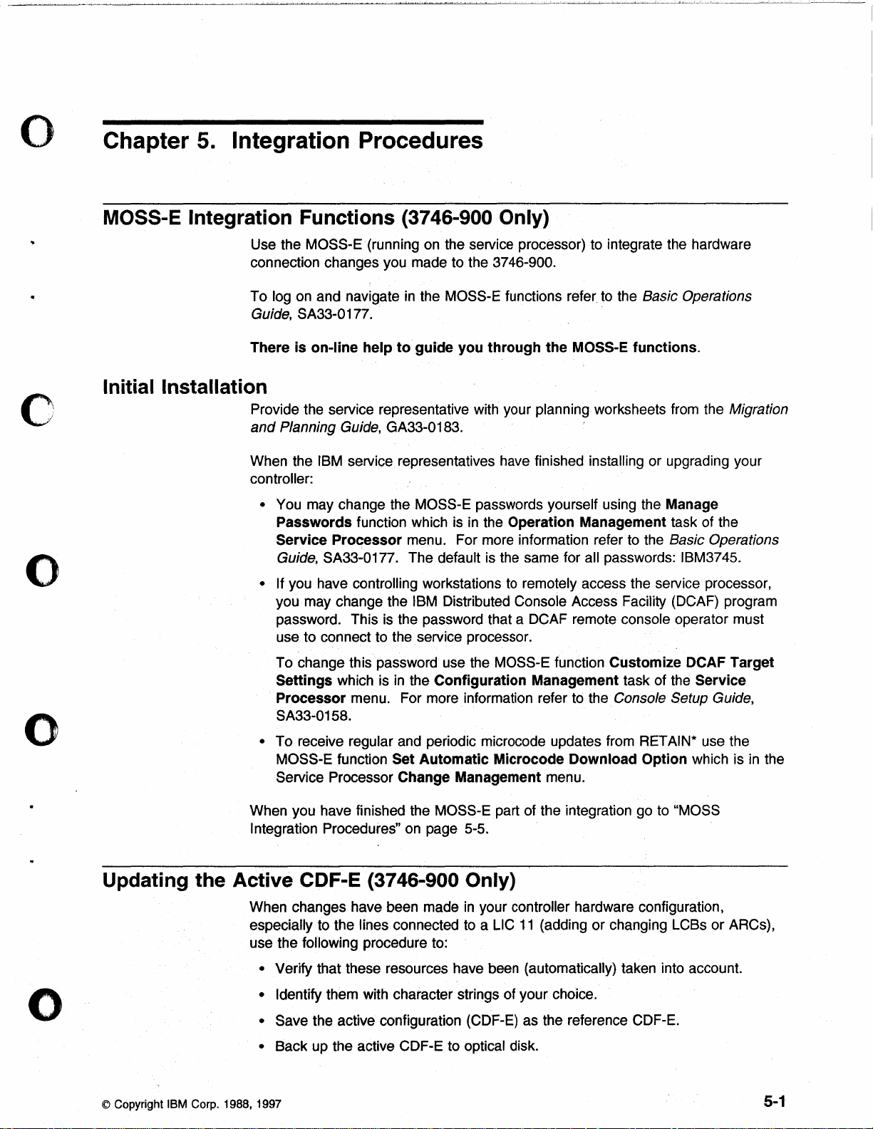
o
Chapter
5.
Integration Procedures
o
MOSS-E Integration
Use the MOSS
connection changes you made to the
To log on and navigate
Guide,
There
Initial Installation
Provide the service representative with your planning worksheets from the Migration
and
Planning Guide, GA33-0183.
When the
controller:
•
You may change the MOSS-E passwords yourself using the Manage
Passwords
Service
Guide,
• If
you may change the
password. This
use to connect to the service processor.
Functions
..
E·
SA33-0177.
is
on-line
IBM service representatives have finished installing or upgrading your
function which
Processor
SA33-0177. The default is the same for all passwords: IBM3745.
you have controlling workstations
(3746-900 Only)
(running on the service processor) to integrate the hardware
3746-900.
in
the MOSS-E functions refer to the Basic Operations
help
to
guide
menu. For more information refer to the Basic Operations
IBM Distributed Console Access Facility (DCAF) program
is
the password that a DCAF remote console operator must
you
through
is
in
the Operation Management task of the
the
MOSS-E
to
remotely access the service processor,
functions.
o
o
Updating
the
To change this password use the
Settings
Processor
SA33-0158.
To receive regular and periodic microcode updates from RETAIN* use the
•
MOSS-E function Set
Service Processor Change Management menu.
When you have finished the
Integration
Active
When changes have been made
especially to the lines connected to a LlC
use the
• Verify that these resources have been (automatically) taken into account.
• Identify them with character strings of your choice.
• Save the active configuration (CDF-E) as the reference CDF-E.
•
Back up the active CDF-E to optical disk.
which is
Procedures"
in
the
Configuration
menu. For more information refer to the Console Setup Guide,
Automatic
MOSS-Epart of the integration go to "MOSS
on
page 5-5.
CDF-E (3746-900 Only)
following procedure to:
MOSS-E function Customize DCAF Target
Management task of the Service
Microcode
in
your controller hardware configuration,
11
Download
(adding or changing LCSs or ARCs),
Option which is
in
the
© Copyright IBM Corp. 1988, 1997
5-1
 Loading...