

Page 1

3745 Communication Controller Models A
3746 Expansion Unit Model 900
3746 Nways Multiprotocol Controller Model 950
Service Processor
Installation and Maintenance
(Based on 6578)
GY27-0406-01
Page 2

Page 3

3745 Communication Controller Models A
3746 Expansion Unit Model 900
3746 Nways Multiprotocol Controller Model 950
Service Processor
Installation and Maintenance
(Based on 6578)
GY27-0406-01
Page 4

Note
Before using this information and the product it supports, be sure to read the general information under “Notices”
on page xi.
First Edition (October 2001)
This edition applies to the Service Processor based on 6578 Model RAU.
Order publications through your IBM representative or the IBM branch office serving your locality. Publications are not stocked at the
address given below.
A form for readers’ comments appears at the back of this publication. If the form has been removed, address your comments to:
Department CGFA
Design & Information Development
IBM Corporation
PO Box 12195
Research Triangle Park NC 27709
U.S.A.
When you send information to IBM, you grant IBM a nonexclusive right to use or distribute the information in any way it believes
appropriate without incurring any obligation to you.
Copyright International Business Machines Corporation 2001. All rights reserved.
US Government Users Restricted Rights – Use, duplication or disclosure restricted by GSA ADP Schedule Contract with IBM Corp.
Page 5

Contents
Figures . . . . . . . . . . . . . . . . . . . . . . . . . . . . . . . . . . . . . . . . . . ix
Notices . . . . . . . . . . . . . . . . . . . . . . . . . . . . . . . . . . . . . . . . . . xi
European Union (EU) Statement ........................... xii
Year 2000 Statement
Electronic Emission Notices .............................. xii
Korean Communications Statement ....................... xiii
New Zealand Radiocommunications (Radio) Regulations
Trademarks . . . . . . . . . . . . . . . . . . . . . . . . . . . . . . . . . . . . . . . xiv
Service Inspection Procedures ............................ xiv
About This Guide ................................... xv
Who Should Use This Guide
How to Use This Guide ................................ xv
How This Guide Is Organized
Where to Find More Information ........................... xvi
Additional Information on the Web ........................ xvii
Online Documentation from CD-ROM ...................... xvii
Service Personnel Definitions ............................. xvii
................................. xii
........... xiii
............................. xv
............................ xv
Chapter 1. Installing and Setting Up Your Service Processor ....... 1-1
Prerequisite Documentation . . . . . . . . . . . . . . . . . . . . . . . . . . . . . . 1-1
Installation Scenarios . . . . . . . . . . . . . . . . . . . . . . . . . . . . . . . . . 1-3
| Installing Your Service Processor (Based on 6578 Model RAU) ......... 1-7
Service Processor Overview ............................ 1-7
Service Processor Installation Tasks ....................... 1-8
Step 1: Preparing Your Installation ........................ 1-8
Step 2: Installing the System Unit, Display, and Keyboard .......... 1-9
Step 3: Installing the Service Processor Access Unit (8228) ........ 1-18
Step 4: Installing and Connecting the RSF Modem to the Service Processor 1-21
Step 5: Installing and Connecting the 7858 to the Service Processor ... 1-22
7858 Modem Installation ............................. 1-22
Installing the Modem .............................. 1-23
Setting the 7858 Connected to the COM1 Connector (ASYN) ...... 1-25
Saving the Configuration of the 7858 .................... 1-25
Connecting the 7858 .............................. 1-26
Step 6: Installing and Connecting the 7857 to the Service Processor ... 1-27
Telecommunication Cables Part Numbers ................... 1-27
Setting the 7857 Connected to the COM1 Connector (ASYN) ...... 1-31
Saving the Configuration of the 7857 .................... 1-31
Connecting the 7857 to COM1 ........................ 1-31
Step 7: Customizing Your Service Processor ................. 1-33
Completing Your Installation ............................ 1-49
Chapter 2. Service Processor Problem Determination ............ 2-1
MAP: Entry Point for Problem Isolation ..................... 2-1
MAP: Service Processor / Display / Keyboard Problem Isolation ...... 2-7
Chapter 3. Service Processor Troubleshooting ................ 3-1
MAP: Service Processor Troubleshooting .................... 3-1
Copyright IBM Corp. 2001 iii
Page 6

Note about POST error code .......................... 3-1
How to proceed
Beep Symptoms
No Beep Symptoms .............................. 3-17
Display
Keyboard
. . . . . . . . . . . . . . . . . . . . . . . . . . . . . . . . . . . . . . . . . 3-18
. . . . . . . . . . . . . . . . . . . . . . . . . . . . . . . . . . . . . . . 3-19
Printer . . . . . . . . . . . . . . . . . . . . . . . . . . . . . . . . . . . . . . . . . 3-19
Power Supply
. . . . . . . . . . . . . . . . . . . . . . . . . . . . . . . . . . . . . 3-20
20-Pin Main Power Supply Connection ..................... 3-20
Undetermined Problems
Before Replacing a System Board
Devices List
. . . . . . . . . . . . . . . . . . . . . . . . . . . . . . . . . . . . . . 3-23
Hard Disk Drive Boot Error ............................. 3-24
When to Use the Low-Level Format Program ................. 3-24
Preparing the Hard Disk Drive for Use ..................... 3-24
Token-Ring Adapter Card LED Status
Token-Ring Table Terms and Definitions ................... 3-26
Additional Service Information
Security Features . . . . . . . . . . . . . . . . . . . . . . . . . . . . . . . . . 3-27
Passwords . . . . . . . . . . . . . . . . . . . . . . . . . . . . . . . . . . . 3-27
Vital Product Data ............................... 3-28
Management Information Format (MIF) ................... 3-28
Alert on LAN .................................. 3-29
Hard-Disk Drive Jumper Settings ........................ 3-30
CD-ROM, PD/CD-ROM Drive Jumper Settings ................ 3-31
BIOS Levels . . . . . . . . . . . . . . . . . . . . . . . . . . . . . . . . . . . . 3-32
Flash (BIOS/VPD) Update Procedure ..................... 3-33
Flash Recovery Boot Block ........................... 3-33
Power Management . . . . . . . . . . . . . . . . . . . . . . . . . . . . . . . . 3-34
Automatic Configuration and Power Interface (ACPI) BIOS ....... 3-34
Advanced Power Management ........................ 3-34
Automatic Hardware Power Management features ............ 3-34
Setting Automatic Hardware Power Management Features ....... 3-35
Automatic Power-On Features ........................ 3-35
Network Settings . . . . . . . . . . . . . . . . . . . . . . . . . . . . . . . . . 3-35
Flash Over LAN (Update POST/BIOS Over Network) ............ 3-36
Wake on LAN ................................... 3-36
System Board Memory .............................. 3-37
................................. 3-1
. . . . . . . . . . . . . . . . . . . . . . . . . . . . . . . . 3-15
. . . . . . . . . . . . . . . . . . . . . . . . . . . . . . . 3-22
....................... 3-22
....................... 3-25
........................... 3-27
Chapter 4. Service Processor Diagnostics and Test Information ..... 4-1
Power-On Self-Test . . . . . . . . . . . . . . . . . . . . . . . . . . . . . . . . . . 4-1
POST Beep Codes ................................... 4-1
Error Code Format ................................... 4-2
Diagnostics Test Programs .............................. 4-3
IBM PC Enhanced Diagnostics .......................... 4-3
Starting the IBM PC Enhanced Diagnostics Program ............ 4-4
Navigating through the Diagnostic Programs ................. 4-4
Running Diagnostic Tests ............................ 4-4
Test Selection . . . . . . . . . . . . . . . . . . . . . . . . . . . . . . . . . . 4-4
IBM PC Enhanced Memory Diagnostics ....................... 4-5
Alert on LAN Test ................................... 4-5
Asset ID Test ...................................... 4-5
Test Results . . . . . . . . . . . . . . . . . . . . . . . . . . . . . . . . . . . . . . . 4-6
Hard File Smart Test .................................. 4-6
iv 3745-XXA iv 3746-9X0: 6578 SPIM
Page 7

IBM Fixed Disk Optimized Test ............................ 4-6
Quick and Full Erase - Hard Drive
Asset EEPROM Backup
................................ 4-7
Viewing the Test Log ................................. 4-8
SIMM/DIMM Memory Errors
IBM PC Enhanced Diagnostic Error Codes
.......................... 4-7
............................ 4-8
..................... 4-9
Chapter 5. Service Processor FRUs / Display Exchange
.......... 5-1
Display Removal/Display Install ........................... 5-1
Removing and Installing Service Processor FRU
Battery Exchange
Board Exchange
. . . . . . . . . . . . . . . . . . . . . . . . . . . . . . . . . . 5-4
. . . . . . . . . . . . . . . . . . . . . . . . . . . . . . . . . . . 5-4
................. 5-2
Processor Exchange . . . . . . . . . . . . . . . . . . . . . . . . . . . . . . . . 5-5
Hard Disk Drive Exchange ............................. 5-6
CD-ROM Drive Exchange ............................. 5-7
Diskette Drive Exchange
.............................. 5-7
Token-Ring Adapter Card Exchange ....................... 5-8
Other FRUs Exchange
............................... 5-9
After FRU Exchange .................................. 5-9
After Battery or Board Exchange ........................ 5-10
After Token-Ring Adapter Card Exchange ................... 5-10
After Hard Disk Drive Exchange ........................ 5-12
After Other FRU Exchanges ........................... 5-15
Chapter 6. CE Leaving Procedure ........................ 6-1
Appendix A. Safety Information . . . . . . . . . . . . . . . . . . . . . . . . . A-1
General Safety . . . . . . . . . . . . . . . . . . . . . . . . . . . . . . . . . . . . A-1
Electrical Safety . . . . . . . . . . . . . . . . . . . . . . . . . . . . . . . . . . A-2
Safety Inspection Guide ............................. A-3
Handling Electrostatic Discharge-Sensitive Devices ............. A-4
Grounding Requirements . . . . . . . . . . . . . . . . . . . . . . . . . . . . . A-4
Safety Notices (Multilingual Translations) ..................... A-5
| Appendix B. Specifications 6578 . . . . . . . . . . . . . . . . . . . . . . . . B-1
Appendix C. Parameter Worksheets . . . . . . . . . . . . . . . . . . . . . . C-1
Controller Integration . . . . . . . . . . . . . . . . . . . . . . . . . . . . . . . . . C-1
Controller Names . . . . . . . . . . . . . . . . . . . . . . . . . . . . . . . . . C-1
Set Power ON Schedule ............................. C-1
MOSS-E Database Optimization ........................ C-1
NCP Dump Transfer ................................. C-1
Service Processor Integration ............................ C-2
Definition of Service Processor LAN Address ................. C-2
Service Processor LAN Management Definition ................ C-2
Definition of the Service Processor in an SNA/Subarea Network ...... C-2
Definition of Service Processor in an APPN/HPR Network ......... C-2
3746-900 Integration . . . . . . . . . . . . . . . . . . . . . . . . . . . . . . . . . C-2
Definition of 3746-900 LAN Address ...................... C-2
Definition of Service LAN IP Addresses .................... C-2
Network Routing Protocol for Each Processor Type ............... C-3
Password . . . . . . . . . . . . . . . . . . . . . . . . . . . . . . . . . . . . . . . C-3
DCAF Remote Logon Password ........................ C-3
Disable Incoming Calls (to Service Processor) ................ C-3
Contents v
Page 8

Parameter Definitions for Reporting Alerts to NetView ............. C-3
Network Node Processor Alerts
MOSS-E Alerts: Mainstream Path Definition
APPN/HPR Network . . . . . . . . . . . . . . . . . . . . . . . . . . . . . . C-3
SNA/Subarea Network
MOSS-E Alerts: Alternate Path Definition
Generate MOSS-E Alerts ............................ C-4
Performance Management CM/2 Parameters (NPM)
Service Processor Parameters for DCAF using CM/2 .............. C-4
For LAN-Attached Consoles
For SNA-Attached Consoles
For APPN/HPR-Attached Consoles
For IP-Attached Consoles ............................ C-4
For Modem-Attached Consoles ......................... C-4
Parameter Definitions for Point-to-Point Link Definition ............. C-5
Parameter Definitions for RSF
Customer Information . . . . . . . . . . . . . . . . . . . . . . . . . . . . . . . C-5
Remote Support Facility Authorization
Set Automatic Microcode Download Option .................. C-5
......................... C-3
.................. C-3
. . . . . . . . . . . . . . . . . . . . . . . . . . . . C-4
................... C-4
.............. C-4
........................... C-4
........................... C-4
....................... C-4
........................... C-5
..................... C-5
Appendix D. Supported Connections between the Service Processor and
a Remote Workstation .............................. D-1
Appendix E. Use of the 7855 Buttons: ←, ↑, →, and ↓ ........... E-1
Appendix F. Controller Expansion Component Locations .......... F-1
Appendix G. Service Processor External Cable References ....... G-1
Service Processor and Network Node Processor Cables for the 3746-900 . G-1
Service Processor and Network Node Processor Cables for the 3746-950 . G-2
Service Processor Cables for the 3745 Models 21A, 31A, 41A, 61A, and 17A G-3
Cable from the Service Processor Processor to the 8228 ........... G-4
Interchange Circuit for Standard LAN Cable ................... G-4
Cable from the Service Processor to the External Modem for RSF ...... G-5
Modem Cable (PN 0782985) ........................ G-5
Interchange Circuits for the Cables between the Service Processor and
the Modem . . . . . . . . . . . . . . . . . . . . . . . . . . . . . . . . . . G-5
Modem Cable (PN 0782984) ........................ G-6
Interchange Circuits for the Modem Adapter Cable ............ G-6
Cable between the Service Processor and the Display ............. G-7
Interchange Circuits for the Extender Cable between the Service
Processor and the Display ......................... G-7
Cables between the Keyboard, the Mouse and the Service Processor .... G-8
Keyboard Extender Cable .............................. G-8
Mouse Extender Cable ............................... G-8
Appendix H. Service Processor Aids ..................... H-1
Computer Exploded View .............................. H-1
Input/Output Connectors . . . . . . . . . . . . . . . . . . . . . . . . . . . . . H-2
Cover Removal . . . . . . . . . . . . . . . . . . . . . . . . . . . . . . . . . . H-2
| Cover Replacement . . . . . . . . . . . . . . . . . . . . . . . . . . . . . . . . H-2
Front Bezel . . . . . . . . . . . . . . . . . . . . . . . . . . . . . . . . . . . . . H-3
EMC Shield . . . . . . . . . . . . . . . . . . . . . . . . . . . . . . . . . . . . H-3
| Diskette / Hard Drive Removal ......................... H-3
vi 3745-XXA vi 3746-9X0: 6578 SPIM
Page 9

CD-ROM Drive Removal ............................. H-4
Power Supply Removal
System Board Layout
System Board Locations ............................. H-5
System Board Switch Settings
Diskette Write Access Switch (SW1-1)
Clear CMOS Switch (SW1-2) ......................... H-7
Service Processor Configuration / Setup Utility
| Service Processor Configuration Reference Based on 6578-RAU ..... H-8
Appendix I. Service Processor Part Numbers ................. I-1
| Parts Listing
. . . . . . . . . . . . . . . . . . . . . . . . . . . . . . . . . . . . . I-2
Appendix J. Bibliography . . . . . . . . . . . . . . . . . . . . . . . . . . . . . . J-1
Customer Documentation for the 3746 Model 950 ................. J-1
Service Documentation for the IBM 3746 Model 950
Customer Documentation for the 3745 (All Models) and 3746 (Model 900) . J-10
| Additional Customer Documentation for the 3745 Models 130, 150, 160, and
| 170
. . . . . . . . . . . . . . . . . . . . . . . . . . . . . . . . . . . . . . . . . . J-16
Service Documentation for the IBM 3745 (Models 210, 21A, 310, 31A, 410,
41A, 610, and 61A) and 3746 (Model 900) ................... J-17
Additional Service Documentation for the IBM 3745 Models 130, 150, 160,
170, and 17A .................................... J-22
.............................. H-4
............................... H-5
.......................... H-7
................... H-7
.................. H-8
............... J-6
Glossary . . . . . . . . . . . . . . . . . . . . . . . . . . . . . . . . . . . . . . . X-1
Index . . . . . . . . . . . . . . . . . . . . . . . . . . . . . . . . . . . . . . . . . . X-3
Contents vii
Page 10

viii 3745-XXA viii 3746-9X0: 6578 SPIM
Page 11

Figures
1-1. Service Processor Environment ...................... 1-7
1-2. Installing Label on the Front Side of the Service Processor ..... 1-10
1-3. Installing Brackets PN 58G5752 ..................... 1-10
1-4. Installing Plate PN 58G5755 ....................... 1-11
1-5. Installing Captive Nuts for the Service Drawer
1-6. Installing the Service Drawer ....................... 1-12
1-7. Installing the Service Processor Unit in the Controller Expansion
(Front Side)
1-8. Installing the Display in the Controller Expansion (Front Side) ... 1-13
1-9. Installing the Keyboard .......................... 1-14
1-10. Cable Locations . . . . . . . . . . . . . . . . . . . . . . . . . . . . . . 1-15
1-11. Installing the Display and Keyboard on a Table ............ 1-15
1-12. Power Cords Connection
1-13. Power Cord for Power Strip ....................... 1-17
1-14. Use of the 8228 Setup Aid
1-15. Installing the 8228 (Controller Expansion Rear Side) ......... 1-19
1-16. Connecting the 8228 to the Service Processor ............ 1-20
1-17. Connecting the 8228 to the Service Processor Installed in the
Controller Expansion . . . . . . . . . . . . . . . . . . . . . . . . . . . 1-20
1-18. 7858 Front Side .............................. 1-22
1-19. 7858 Rear Panel .............................. 1-22
1-20. 7858 Operator Panel Display ....................... 1-23
1-21. 7858 Operator Panel Display ....................... 1-24
| 1-22. Connecting the Service Processor (6578) from COM1 to the 7858 . 1-26
1-23. Installing the 7858 in the Controller Expansion ............ 1-26
1-24. 7857 Front Panel ............................. 1-27
1-25. 7857 Rear Panel .............................. 1-28
1-26. 7857 Operator Panel Display ....................... 1-30
| 1-27. Connecting the Service Processor (6578) from COM1 to the 7857 . 1-31
1-28. Installing the 7857 in the Controller Expansion ............ 1-32
1-29. MOSS-E View Primary Panel ...................... 1-34
1-30. Service Processor Customization .................... 1-35
1-31. Customer Information Customization .................. 1-36
1-32. SP Time and Date Customization .................... 1-36
1-33. Service LAN Addresses .......................... 1-37
1-34. NetView Links . . . . . . . . . . . . . . . . . . . . . . . . . . . . . . . 1-38
1-35. NetView Link/Reporting Customization ................. 1-39
1-36. Example of Switched Major Node Definition .............. 1-40
1-37. Example of NCP Generation for an SDLC Link to NetView ..... 1-41
1-38. Example of NCP Generation for a LAN Link to NetView ....... 1-41
1-39. Token-Ring 3270 Session Customization ................ 1-42
1-40. CCM Remote Configuration Panel .................... 1-42
1-41. Example of a Switched Major Node Definition ............. 1-43
1-42. Retain Customization . . . . . . . . . . . . . . . . . . . . . . . . . . . 1-44
1-43. DCAF Links . . . . . . . . . . . . . . . . . . . . . . . . . . . . . . . . . 1-45
1-44. DCAF Customization . . . . . . . . . . . . . . . . . . . . . . . . . . . 1-46
1-45. Point-to-Point Protocol Configuration .................. 1-47
1-46. Java Console Configuration ....................... 1-48
1-47. SP Customization Message ....................... 1-48
1-48. SP Customization In Progress ...................... 1-49
. . . . . . . . . . . . . . . . . . . . . . . . . . . . . . . . . 1-13
......................... 1-16
........................ 1-18
............. 1-11
Copyright IBM Corp. 2001 ix
Page 12

1-49. SP Customization Completed ...................... 1-49
1-50. SP Reboot
2-1. AC Outlet Distribution Box Connections in Controller Rack
2-2. LAN attached to the Service Processor .................. 2-7
3-1. Keyboard Connector Voltages
3-2. Drive Connector Labels
5-1. Screw Locations . . . . . . . . . . . . . . . . . . . . . . . . . . . . . . . 5-5
5-2. Customization Panel
E-1. 7855 Front Panel ............................. E-1
F-1. Controller Expansion Inventory Chart (Front View)
F-2. Controller Expansion Inventory Chart (Rear View)
F-3. Installing Captive Nuts and Brackets for the Display, Drawer, SP and
NNP Based on PC Type 6578
F-4. Installing Captive Nuts for LCBs ...................... F-5
F-5. Installing Captive Nuts for 8229s ..................... F-6
F-6. Installing Captive Nuts and Brackets for MAE
F-7. Installing Brackets (PN 58G5752) for Processor Type 6578 ...... F-8
F-8. Units Installation in the Controller Expansion (SP and NNP Type
6578)
F-9. Units Installation in the Controller Expansion (SP and NNP Type 6578
+ MAE) . . . . . . . . . . . . . . . . . . . . . . . . . . . . . . . . . . . . F-9
F-10. Connecting the Units to the ac Outlet Distribution Box ........ F-10
G-1. Service Processor and Network Node Processor Cables for 3746-900 G-1
G-2. Service Processor and Network Node Processor Cables for 3746-950 G-2
G-3. Service Processor Cables for 3745 Models xxA ............ G-3
G-4. LAN Cable . . . . . . . . . . . . . . . . . . . . . . . . . . . . . . . . . G-4
G-5. Cable between the Service Processor and the Modem (PN 0782985) G-5
G-6. Modem Cables Pin Assignments (PN 0782985) ............ G-5
G-7. Modem Cable Adapter (PN 0782984) .................. G-6
G-8. Modem Cables Pin Assignments (PN 0782984) ............ G-6
G-9. Cables between the Service Processor and the Display ....... G-7
G-10. Extender Cable for Service Processor and Display connection ... G-7
G-11. Cables between the Service Processor and the Display ....... G-8
G-12. Keyboard Extender Cable ........................ G-8
G-13. Mouse Extender Cable .......................... G-8
. . . . . . . . . . . . . . . . . . . . . . . . . . . . . . . . . 1-49
...... 2-2
...................... 3-19
.......................... 3-31
. . . . . . . . . . . . . . . . . . . . . . . . . . . . 5-15
........... F-2
........... F-3
....................... F-4
.............. F-7
. . . . . . . . . . . . . . . . . . . . . . . . . . . . . . . . . . . . . F-9
x 3745-XXA x 3746-9X0: 6578 SPIM
Page 13

Notices
This information was developed for products and services offered in the U.S.A.
IBM may not offer the products, services, or features discussed in this document in
other countries. Consult your local IBM representative for information on the
products and services currently available in your area.
References in this publication to IBM products, programs, or services do not imply
that IBM intends to make these available in all countries in which IBM operates.
Any reference to an IBM product, program, or service is not intended to state or
imply that only IBM’s product, program, or service may be used. Any functionally
equivalent product, program, or service that does not infringe any of IBM’s
intellectual property rights may be used instead of the IBM product, program, or
service. Evaluation and verification of operation in conjunction with other products,
except those expressly designated by IBM, are the user’s responsibility.
IBM may have patents or pending patent applications covering subject matter in
this document. The furnishing of this document does not give you any license to
these patents. You can send license inquiries, in writing, to:
IBM Director of Licensing
IBM Corporation
North Castle Drive
Armonk, NY 10504-1785
U.S.A.
For license inquiries regarding double-byte (DBCS) information, contact the IBM
Intellectual Property Department in your country or send inquiries, in writing, to:
IBM World Trade Asia Corporation
Licensing
2-31 Roppongi 3-chome, Minato-ku
Tokyo 106, Japan
The following paragraph does not apply to the United Kingdom or any other country
where such provisions are inconsistent with local law:
INTERNATIONAL BUSINESS MACHINES CORPORATION PROVIDES THIS
PUBLICATION "AS IS" WITHOUT WARRANTY OF ANY KIND, EITHER EXPRESS
OR IMPLIED, INCLUDING, BUT NOT LIMITED TO, THE IMPLIED WARRANTIES
OF NON-INFRINGEMENT, MERCHANTABILITY OR FITNESS FOR A
PARTICULAR PURPOSE. Some states do not allow disclaimer of express or
implied warranties in certain transactions, therefore, this statement may not apply to
you.
This information could include technical inaccuracies or typographical errors.
Changes are periodically made to the information herein; these changes will be
incorporated in new editions of the publication. IBM may make improvements
and/or changes in the product(s) and/or the program(s) described in this publication
at any time without notice.
This information is for planning purposes only. The information herein is subject to
change before the products described become available.
Copyright IBM Corp. 2001 xi
Page 14

European Union (EU) Statement
This product is in conformity with the protection requirements of EU Council
Directive 89/336/EEC on the approximation of the laws of the Member States
relating to electromagnetic compatibility. IBM can not accept responsibility for any
failure to satisfy the protection requirements resulting from a non-recommended
modification of the product, including the fitting of non-IBM option cards.
Year 2000 Statement
This product is Year 2000 ready. When used in accordance with its associated
documentation, it is capable of correctly processing, providing, and/or receiving
date data within and between the 20th and 21st centuries, provided all other
products (for example, software, hardware, and firmware) used with the product
properly exchange accurate date data with it.
Electronic Emission Notices
Federal Communications Commission (FCC) Statement
Note: This equipment has been tested and found to comply with the limits for a
Class A digital device, pursuant to Part 15 of the FCC Rules. These limits are
designed to provide reasonable protection against harmful interference when the
equipment is operated in a commercial environment. This equipment generates,
uses, and can radiate radio frequency energy and, if not installed and used in
accordance with the instruction manual, may cause harmful interference to radio
communications. Operation of this equipment in a residential area is likely to cause
harmful interference, in which case the user will be required to correct the
interference at his own expense.
Properly shielded and grounded cables and connectors must be used in order to
meet FCC emission limits. IBM is not responsible for any radio or television
interference caused by using other than recommended cables and connectors or by
unauthorized changes or modifications to this equipment. Unauthorized changes or
modifications could void the user's authority to operate the equipment.
This device complies with Part 15 of the FCC Rules. Operation is subject to the
following two conditions: (1) this device may not cause harmful interference, and
(2) this device must accept any interference received, including interference that
may cause undesired operation.
Industry Canada Compliance Statement
This Class A digital apparatus complies with Canadian ICES-003.
Avis de conformité aux normes d'Industrie Canada
Cet appareil numérique de la classe A est conform à la norme NMB-003 du
Canada.
Japanese Voluntary Control Council For Interference (VCCI) Statement
This equipment is in the 1st Class category (information equipment to be used in
commercial and/or industrial areas) and conforms to the standards set by the
xii 3745-XXA xii 3746-9X0: 6578 SPIM
Page 15
Voluntary Control Council for Interference by Information Technology Equipment
aimed at preventing radio interference in commercial and industrial areas.
Consequently, when used in a residential area or in an adjacent area thereto, radio
interference may be caused to radios and TV receivers, and so on.
Read the instructions for correct handling.
Power Line Harmonics (JEIDA) Statement
The guidelines of power line harmonics required by JEIDA are satisfied.
Korean Communications Statement
Please note that this device has been certified for business purpose with regard to
electromagnetic interference. If you find this is not suitable for your use, you may
exchange it for one of residential use.
New Zealand Radiocommunications (Radio) Regulations
Attention: This is a Class A product. In a domestic environment this product may
cause radio interference in which case the user may be required to take adequate
measures.
Taiwanese Class A Warning Statement
This is a Class A product. In a domestic environment this product may cause radio
interference in which case the user will be required to take adequate measures.
Notices xiii
Page 16

Trademarks
The following terms are trademarks of International Business Machines Corporation
in the United States, or other countries, or both:
ACF/VTAM
AIX
Alert on LAN
APPN
AS/400
AssetID
AT
DATABASE 2
DB2
Enterprise Systems Connection Architecture
ES/3090
ES/9000
ESCON
Fax Concentrator
HelpCenter
IBM
LPDA
Micro Channel
MVS/ESA
Nways
OS/2
Parallel Sysplex
PowerPC (logo)
RETAIN
S/370
S/390
System/36
VM/ESA
VTAM
Wake on LAN
NetView and Tivoli are trademarks of Tivoli Systems, Inc. in the United States, or
other countries, or both.
Java and all Java-based trademarks and logos are trademarks or registered
trademarks of Sun Microsystems, Inc. in the United States and/or other countries.
Microsoft, Windows, Windows NT, and the Windows logo are trademarks or
registered trademarks of Microsoft Corporation.
Pentium is a registered trademark of Intel Corporation in the U.S. and other
countries.
UNIX is a registered trademark of the Open Group in the United States and other
countries.
Other company, product, and service names may be trademarks or service marks
of others.
Service Inspection Procedures
The Service Inspection Procedures help service personnel check whether the
3745/3746 conforms to IBM safety criteria. They have to be used each time the
3745/3746 safety is suspected. The Service Inspection Procedures section is
located at the beginning of the:
3745 Communication Controller Models 210 to 61A Maintenance Information
Procedures, SY33-2054
3745 Communication Controller Models 130 to 17A Maintenance Information
Procedures, SY33-2070
3746-950 Service Guide, SY33-2108.
3746-900 Service Guide, SY33-2116.
For the Service Processor, see the Service Inspection Procedures in “Safety
Inspection Guide” on page A-3.
xiv 3745-XXA xiv 3746-9X0: 6578 SPIM
Page 17

About This Guide
This guide provides installation and maintenance information for the Service
Processor.
Who Should Use This Guide
The IBM personnel using this guide should be:
Trained to service the Service Processor, IBM 3745 Communication Controller,
3746-900, and 3746-950.
Familiar with the configuration of the 3745 Communication Controller,
3746-900, and 3746-950.
Familiar with the Service Processor service documentation.
How to Use This Guide
This guide provides procedures for installing and maintaining a Service Processor.
To ensure the most efficient installation:
Read the instructions carefully before attempting to do them.
Complete each step before going to the next one.
Go through the chapters sequentially.
How This Guide Is Organized
Chapter 1 Presents the procedures for installing and connecting the Service
Processor, the 8228, and the RSF modem. It also gives
procedures to customize the MOSS-E parameters.
Chapter 2 Introduces to the Service Processor problem determination.
Chapter 3 Provides maintenance analysis procedures (MAPs) and
troubleshooting information for the Service Processor.
Chapter 4 Describes the diagnostics and tests available on the Service
Processor and how to invoke them.
Chapter 5 Describes the procedures for Service Processor FRU exchange.
Chapter 6 Describes the service representative leaving procedure.
| Appendix A Provides safety notices for the Service Processor.
| Appendix B Provides 6578 machine model specifications.
| Appendix C Provides parameter worksheets for the Service Processor.
| Appendix D Provides the supported connections between the Service Processor
| and a remote workstation.
| Appendix E Explains how to use the 7855 modem buttons.
| Appendix F Gives the component locations in the controller expansion
| Appendix G Gives the external cable references.
Copyright IBM Corp. 2001 xv
Page 18

| Appendix H Provides Service Processor aids for FRU location and removal, and
| for configuration and setup.
| Appendix I Provides Service Processor part numbers.
| Appendix J Gives the customer and service documentation bibliography.
Glossary X Gives a list of abbreviations.
Where to Find More Information
For a complete list of the Service Processor, 3745, 3746-900, and 3746-950
customer and service information manuals, see at the end of this manual. In this
SPIM, references are made to the following publications:
3746-950 Installation Guide, SY33-2107
3746-900 Installation Guide, SY33-2114
| 3746-950 IG: 3746-950 Installation Guide, SY33-2107
| 3745/130-17A Installation Guide, SY33-2067
3745 Communication Controller Models 210 to 61A Maintenance Information
Procedures, SY33-2054
3745 Communication Controller Models 130 to 17A Maintenance Information
Procedures, SY33-2070
3746-950 Service Guide, SY33-2108
3746-900 Service Guide, SY33-2116
| Service Processor and Network Node Processor Service User, SY33-2127
3745 Communication Controller Models A and 3746 Models 900 and 950:
Overview, Installation, and Integration, GA27-4234
3745 Communication Controller Models A and 3746 Models 900 and 950:
Serial Line Adapters, GA27-4235
3745 Communication Controller Models A and 3746 Models 900 and 950:
Token Ring and Ethernet, GA27-4236
3745 Communication Controller Models A and 3746 Models 900 and 950:
ESCON Channels, GA27-4237
3745 Communication Controller Models A and 3746 Models 900 and 950:
Physical Planning, GA27-4238
3745 Communication Controller Models A and 3746 Models 900 and 950:
Management Planning, GA27-4239
3745 Communication Controller Models A and 3746 Models 900 and 950:
Multiaccess Enclosure Planning, GA27-4240
3745 Communication Controller Models A and 3746 Models 900 and 950:
Protocol Introductions, GA27-4241
xvi 3745-XXA xvi 3746-9X0: 6578 SPIM
Page 19

Additional Information on the Web
You can access the latest news and information about IBM network products,
customer service and support, and microcode upgrades at:
www.ibm.com/networking
Online Documentation from CD-ROM
| Starting at EC H10000A and EC H10010A (and above), the Service Processor is
| shipped with a CD-ROM that contains the licensed internal code and a copy of the
| 3746 Web site. You will find marketing, product engineering, and other information
about CCP products on this Web page.
To access this page:
1. Insert the CD-ROM into the CD-ROM disk drive of the Service Processor.
2. From the MOSS-E primary menu, click Information
3. Double-click CD-ROM documentation
4. If you want to display the CCP documentation, click Go to Documentation
Note: To see the latest version of the Web site, go to:
w3.lagaude.ibm.com/ccp/3746.htm
Service Personnel Definitions
See one of the following manuals:
3745 Communication Controller Models 210 to 61A Maintenance Information
Procedures, SY33-2054
3745 Communication Controller Models 130 to 17A Maintenance Information
Procedures, SY33-2070
3746-950 Service Guide, SY33-2108
3746-900 Service Guide, SY33-2116
About This Guide xvii
Page 20

xviii 3745-XXA xviii 3746-9X0: 6578 SPIM
Page 21

Chapter 1. Installing and Setting Up Your Service Processor
This chapter describes a number of installation scenarios and the tasks involved in
each scenario, and provides detailed installation steps.
Prerequisite Documentation
Note: The following list gives the references to all the documents that can be used
during the installation, but depending on your installation scenario not all of the
documents will be needed.
Documents used during the installation:
1. 3746-900 IG: 3746-900 Installation Guide, SY33-2114 (see note 1)
2. 3745 IG: 3745/210-61A Installation Guide, SY33-2057 (see note 2)
3. 3746-950 IG: 3746-950 Installation Guide, SY33-2107 (see note 4)
4. 3745/130-17A Installation Guide, SY33-2067 (see note 3)
5. Output from the standalone Controller Configuration and Management.
6. SPIM:
Service Processor Installation and Maintenance (Based on 7585, 3172, and
9585), SY33-2120
Service Processor Installation and Maintenance (Based on 6275),
SY33-2125
Service Processor Installation and Maintenance (Based on 6563),
SY27-0393
| Service Processor Installation and Maintenance (Based on 6578),
| GY27-0406
7. NNPIM:
Network Node Processor Installation and Maintenance (Based on 7585 or
3172), SY33-2112
Network Node Processor Installation and Maintenance (Based on 6275),
SY33-2126
Network Node Processor Installation and Maintenance (Based on 6563),
SY27-0394
| Network Node Processor Installation and Maintenance (Based on 6578),
| GY27-0407
8. Service Processor and Network Node Processor Service User, SY33-2127
9. MES: 3745 MES and Field BMs for model conversion
10. 3745 Bypass Card Plugging Guide, SY33-2097 (on line document see note 1)
11. 7855 Modem Model 10 Guide to Operation, GA33-0160 or 7857 Guide to
Operation, GA13-1839
12. Parameter sheets from the 3745 Communication Controller Models A and 3746
Models 900 and 950: Overview, Installation, and Integration, GA27-4234.
Copyright IBM Corp. 2001 1-1
Page 22

Notes:
This document is used when:
1. Installing a 3746-900.
2. Installing a 3745 Model X1A.
3. Installing a 3745 Model 17A.
4. Installing a 3746-950.
5. Installing the MES 3745 models conversion to models A
6. Installing the MES 3746-900 model conversion to 3746-950
1-2 3745-XXA 1-2 3746-9X0: 6578 SPIM
Page 23

Installation Scenarios
Depending on the machine and the MES received, determine which installation
scenario you are going to perform (from Scenario 1 to Scenario 16). See
Table 1-1 on page 1-4 and Table 1-1 on page 1-4 to see how the installation
tasks can be distributed between two service representatives and define which
document must be used to start the installation and have an overview of the
installation sequence.
Note: See Table 1-2 on page 1-4 for more details about each scenario. If you
are installing a 3745 Model 17A, the statements concerning the installation of an
expansion frame and the procedures "CDF verify" and "locate bypass cards
positions" are not applicable.
Note: You can install the 3746-900 first and then connect the Service Processor
and run all diagnostics. Afterward the 3745 can be modified to model A (if
necessary) and connected to the 3746-900
Chapter 1. Installing and Setting Up Your Service Processor 1-3
Page 24

Table 1-1. Installation Scenarios
Machine and/or MES Received Scenario
3745 Model 170 or Model 210 to 610 1
Service Processor 2
3745 MES model conversion and 3746-900 3
3745 MES model conversion and 3746-900 and Service Processor 4
3745 Model 17A or Model 21A to 61A 5
3745 Model 17A or Model 21A to 61A and Service Processor 6
3746-900 7
3746-900 and 3745 MES model conversion 8
3746-900 and 3745 MES and Service Processor 9
3746-900 and 3745 Model 17A or 21A to 61A 10
3746-900 and 3745 Model 17A or 21A to 61A and Service Processor 11
3746-950 and network node processor 12
3746-950, Service Processor, and Network Node Processor 13
3746-900 MES conversion to Model 3746-950 and network node processor 14
3746-900 MES conversion to Model 3746-950, Service Processor and Network Node
15
Processor
3746-900 MES installation of APPN and network node processor 16
Note: The installation sequence given in Table 1-2 can be modified as you are
able to install the 3746-900 first and then connect to the 3745 model A. It is no
more mandatory to start with the 3745 MES (to migrate to model A) or with the
3745 Installation Guide.
Table 1-2 (Page 1 of 3). Installation Scenario Tasks and Documentation
Scenario CE Tasks Documentation Installation Sequence
Scenario 1 1st Install the 3745-XX0 base
frame.
2nd Install expansion frame (if any). 3745 Installation Guide
Scenario 2 1st Install the Service Processor. Service Processor Installation
Scenario 3 1st Install the MES model
conversion.
Scenario 4 1st Install the MES model
conversion.
2nd Install the Service Processor. Service Processor Installation
Scenario 5 1st Install the 3745-XXA base
frame.
2nd Install expansion frame (if any). 3745 Installation Guide
3745 Installation Guide Start with the 3745 IG and
install the 3745-XX0.
Start with the SPIM and
and Maintenance
MES model conversion XX0 to
XXA
MES model conversion XX0 to
XXA
and Maintenance
3745 Installation Guide Start with the 3745 IG and
install the SP..
Start with the MES and
connect the 3745 XXA to
the existing SP.
Start with the MES and
using the SPIM install the
SP.
connect the 3745-XXA to
the existing SP.
1-4 3745-XXA 1-4 3746-9X0: 6578 SPIM
Page 25

Table 1-2 (Page 2 of 3). Installation Scenario Tasks and Documentation
Scenario CE Tasks Documentation Installation Sequence
Scenario 6 1st Install the 3745-XXA base
frame.
2nd Install the Service Processor. Service Processor Installation
Scenario 7 1st Install the 3746-900 (off line). 3746-900 Installation Guide Start with the 3746 IG and
2nd Prepare the 3745-XXA: CDF
verify, Bypass Cards
2
CEs
Connect the 3746-900 to the
3745.
3745 Installation Guide Start with the 3745 IG and
using the SPIM install and
connect the SP..
and Maintenance
install and connect the
3746-900 to the 3745-XXA.
3746-900 Installation Guide
3746-900 Installation Guide
Scenario 8 1st Install the MES model
conversion and prepare the
3745-XXA.
CDF verify - Bypass Cards
2nd Install the 3746-900 (offline. 3746-900 Installation Guide
2
CEs
Scenario 9 1st Install the MES model
2nd Install the Service Processor. Service Processor Installation
Install the 3746-900 (offline). 3746-900 Installation Guide
2
CEs
Scenario 10 1st Install the 3745-XXA base
2nd Install expansion frame (if any)
2
CEs
Connect the 3746-900 to the
3745.
conversion and prepare the
3745-XXA.
CDF verify - Bypass Cards
Connect the 3746-900 to the
3745.
frame.
and the 3746-900.
Connect the 3746-900 to the
3745.
MES model conversion XX0 to
XXA 3746-900 Installation
Guide
3746-900 Installation Guide
MES model conversion XX0 to
XXA 3746-900 Installation
Guide
and Maintenance
3746-900 Installation Guide
3745 Installation Guide Start with the 3745 IG and
3745 Installation Guide
3746-900 Installation Guide
3746-900 Installation Guide
Start with the MES to
convert the 3745 to model
XXA, then using the 3746
IG install and connect the
3746-900.
Start with the 3745 MES
convert the 3745 to XXA
using the SPIM install the
SP, then using the 3746 IG
install and connect the
3746-900.
install the 3745 XXA.
Then, using the 3746 IG,
install the 3746-900. The
machines are connected to
an existing SP.
Scenario 11 1st Install the 3745-XXA base
frame and the Service
Processor.
2nd Install expansion frame (if any)
and the 3746-900.
2
CEs
Scenario 12 1st Install the 3746-950.. 3746-950 Installation Guide Start with the 3746 IG and
2nd Install the Network Node
Chapter 1. Installing and Setting Up Your Service Processor 1-5
Connect the 3746-900 to the
3745.
Processor.
3745 Installation Guide
Service Processor Installation
3745 Installation Guide
3746-900 Installation Guide
3746-900 Installation Guide
Network Node Processor
Installation and Maintenance
Start with the 3745 IG and
install the 3745 XXA. Then,
using the SPIM, install the
SP. Using the 3746 IG,
install the 3746-900.
connect the 3746 950 to
the existing SP. Then
using the network node
processor installation and
maintenance, install the
NNP.
Page 26

Table 1-2 (Page 3 of 3). Installation Scenario Tasks and Documentation
Scenario CE Tasks Documentation Installation Sequence
Scenario 13 1st Install the 3746-950. 3746-950 Installation Guide Start with the 3746 IG to
install the 3746-950, the
SPIM to install the SP, and
the network node
processor installation and
maintenance to install the
NNP.
2nd Install Service Processor. Service processor Installation
and Maintenance
2nd Install the Network Node
Processor.
Scenario 14 1st Install the MES model
conversion from 3746-900 to
3746-950.
Scenario 15 1st Install the MES model
conversion from 3746-900 to
3746-950
2nd Install the Service Processor. Service Processor Installation
2nd Install the Network Node
Processor.
Network Node Processor
Installation and Maintenance
3746-900 to 3746-950 MES
model conversion and the
3746-950 Installation Guide
3746-900 to 3746-950 MES
model conversion, 3746-950 IG
and the
and Maintenance
Network Node Processor
Installation and Maintenance
Start with the MES, then
use the 3746 IG to connect
the 3746-950 to an existing
SP, and the network node
processor installation and
maintenance to install the
NNP.
Start with the MES and the
3746-950 IG then use the
SPIM to install the SP and
the network node
processor installation and
maintenance to install the
NNP.
Scenario 16 1st Install APPN on the 374-900
MES.
2nd Install the Network Node
Processor.
MES APPN on 3746-900 Start with the MES to
install APPN on the
3746-900, then use the
NNPIM to install the
network node processor.
Network Node Processor
Installation and Maintenance
1-6 3745-XXA 1-6 3746-9X0: 6578 SPIM
Page 27
Installing Your Service Processor (Based on 6578 Model RAU)
|
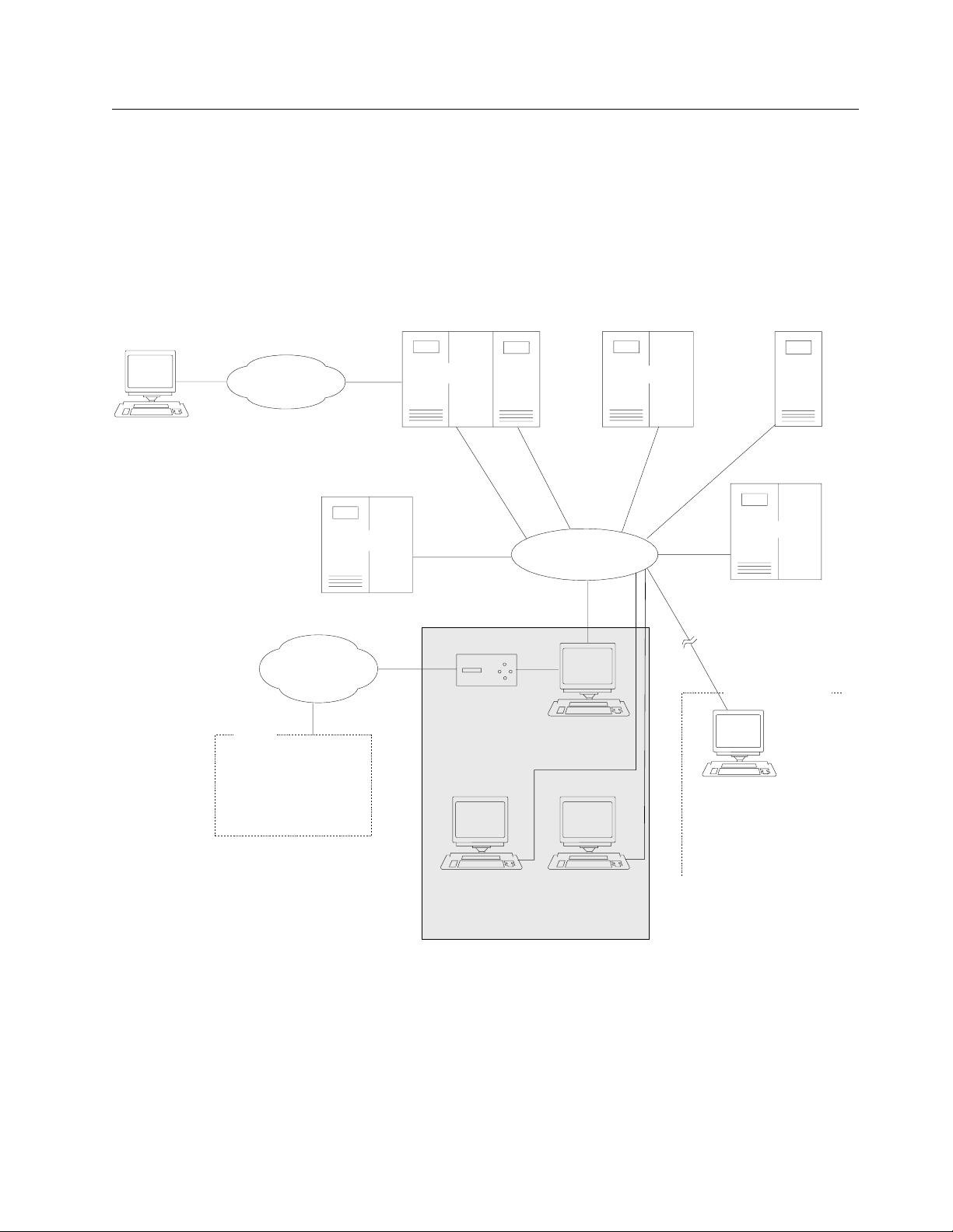
Service Processor Overview
| The Service Processor is based on an IBM 6578 Model RAU, see “Service
| Processor Configuration / Setup Utility” on page H-8 for details of the features
| installed.
DCAF
Remote
Console
SNA
Network
Public
Switched
Network
IBM
RETAIN HOST
REMOTE SUPPORT
3745
3745 3745
900
Token-Ring
LAN
Modem
3746
MOSS-E
Service
Processor
CPCP
3746
950
3745
Control Room
DCAF
LAN-Attached
Console
Network Node
Processor-B
Network Node
Processor-A
Controller Rack
Figure 1-1. Service Processor Environment
Chapter 1. Installing and Setting Up Your Service Processor 1-7
Page 28

Service Processor Installation Tasks
Note: If you are not familiar with the Service Processor operations, refer to Service Processor and
Network Node Processor Service User, SY33-2127, and then return here.
TASK DESCRIPTION GO TO
1 Installation preparation “Step 1: Preparing Your Installation”.
2 Install the System Unit, Display, and Keyboard “Step 2: Installing the System Unit, Display,
and Keyboard” on page 1-9.
3 Install the 8228 and connect to the Service
Processor
4 Install and connect the RSF modem to the Service
Processor
5 Customize your &SO. according to the customer’s
options
“Step 3: Installing the Service Processor
Access Unit (8228)” on page 1-18.
“Step 4: Installing and Connecting the RSF
Modem to the Service Processor” on
page 1-21 .
“Step 7: Customizing Your Service Processor”
on page 1-33.
Step 1: Preparing Your Installation
Obtain from the customer the following parameter worksheets:
1. "Parameter definitions for RSF"
2. "NetView path parameters"
3. "Service Processor integration"
4. "Service Processor parameters for DCAF"
5. "NCP dump transfer" (not applicable for 3746-950)
These parameter worksheets are part of the 3745 Communication Controller
Models A and 3746 Models 900 and 950: Planning Guide, GA33-0457 Appendix A
and must be filled in by the customer. A copy of these parameter worksheets is
given at the end of this manual see Appendix C, “Parameter Worksheets.”
1-8 3745-XXA 1-8 3746-9X0: 6578 SPIM
Page 29
Step 2: Installing the System Unit, Display, and Keyboard
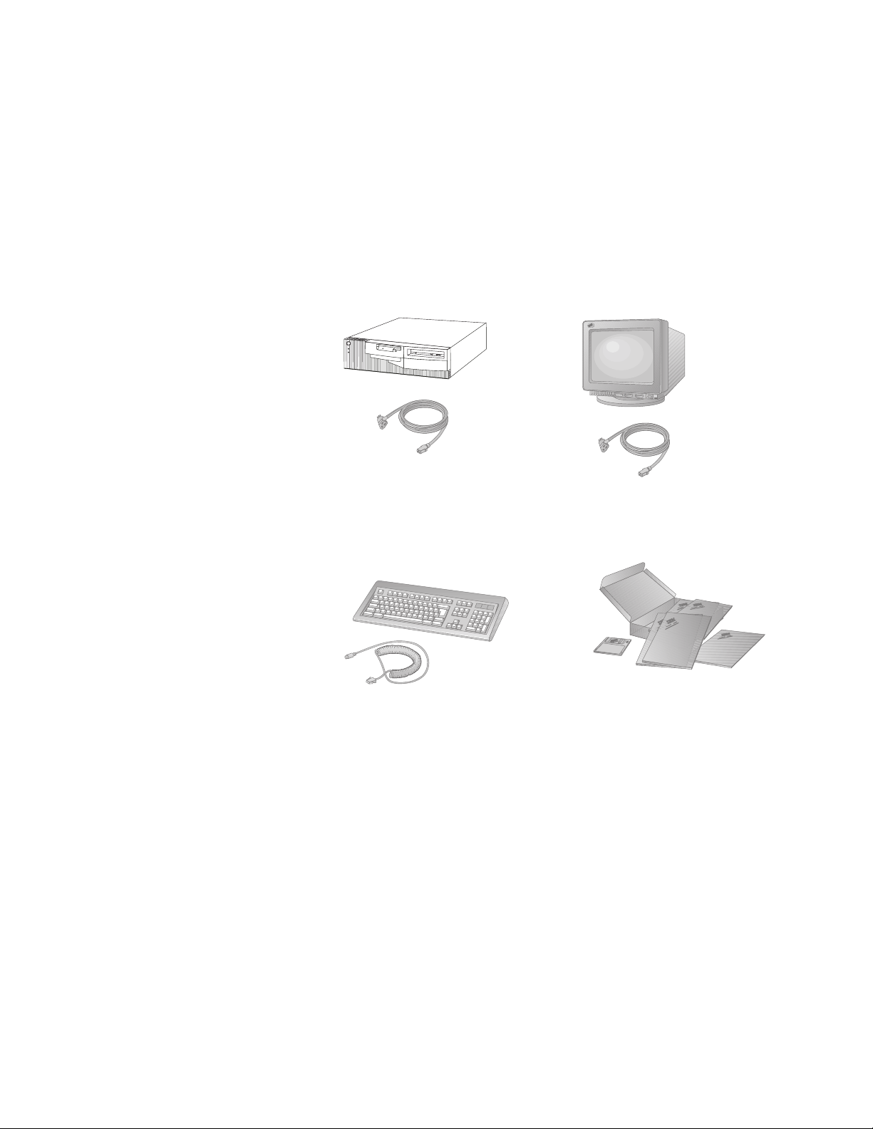
1. Unpack Your Service Processor
You need the following items to complete this installation:
Service Processor and
Power Cord
Keyboard, Mouse,
and Keyboard Cable
Display and
Display Power Cord
Publications and diskettes
2. Check that you have received the following parts:
a. Four brackets (PN 58G5752)
b. Two plates (PN 58G5755)
c. One service drawer assembly (PN 58G5763)
d. One label (PN 0782966)
e. Ten nuts (PN 58G5766)
f. Twelve screws (PN 1621230), eight screws (PN 2665527) and two screws
(PN 1621232)
3. Using label (PN 0782966), identify your Service Processor-A or Service
Processor-B by sticking the appropriate label A on the front side of the unit
(see Figure 1-2 on page 1-10).
Chapter 1. Installing and Setting Up Your Service Processor 1-9
Page 30
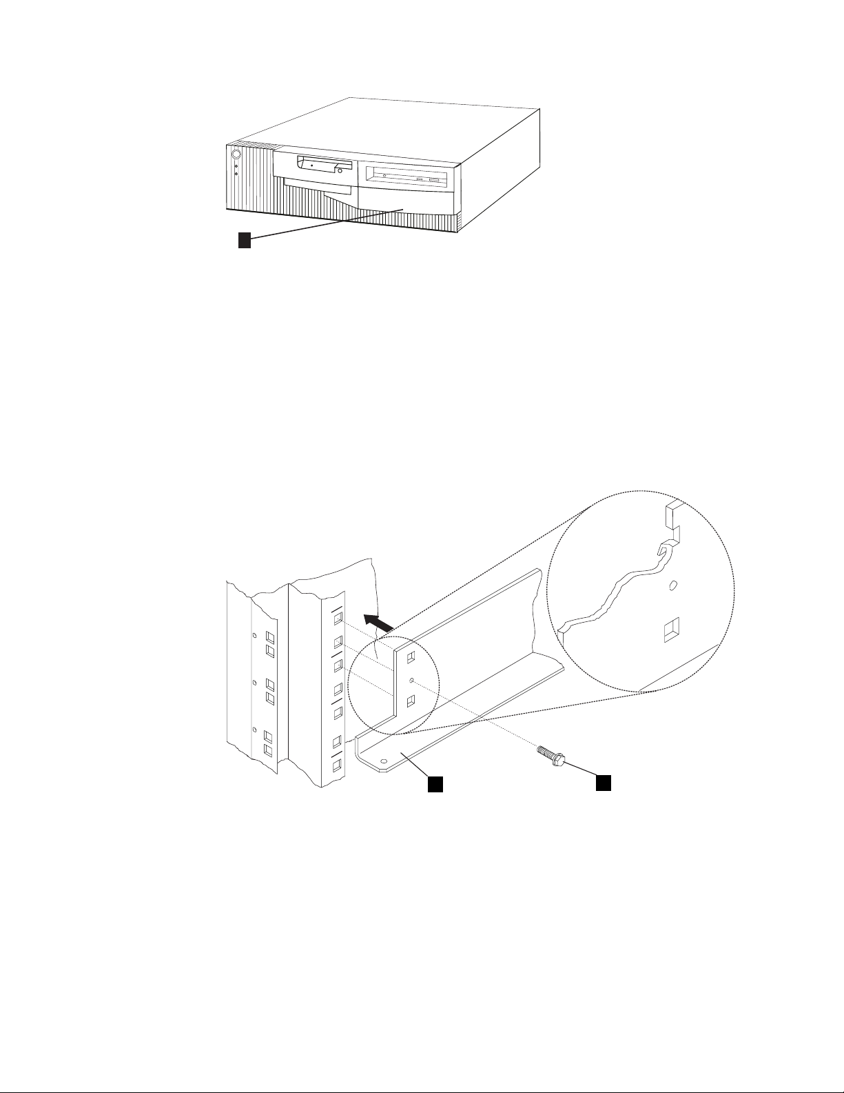
A
Figure 1-2. Installing Label on the Front Side of the Service Processor
4. If you have a controller expansion, install the Service Processor kit PN
58G5698 (service drawer, brackets, and plates), and go to step 5. Otherwise,
go to step 16 on page 1-14.
5. Open the front and rear doors of the controller expansion. See Figure F-3 on
page F-4 and locate the positions to install the brackets for the display and the
Service Processor. Also, locate the position to install the service drawer.
6. For the display and the Service Processor, install four brackets 1 (PN
58G5752) and secure using eight screws 2 (PN 2665527).
X
X
X
X
X
X
1
Figure 1-3. Installing Brackets PN 58G5752
2
7. On the brackets installed for the display and the service processor, install plate
4 (PN 58G5755) using four screws 3 (PN 1621230).
1-10 3745-XXA 1-10 3746-9X0: 6578 SPIM
Page 31

3
4
Figure 1-4. Installing Plate PN 58G5755
8. See Figure 1-5, and if needed, install four captive nuts A (PN 58G5766) on
the front and on the rear side of the controller expansion, to install the service
drawer.
.
Front View
Rear View
23 23
A
22 22
21 21
Drawer
Drawer
20 20
19 19
18 18
Left Side Left SideRight Side Right Side
Figure 1-5. Installing Captive Nuts for the Service Drawer
Chapter 1. Installing and Setting Up Your Service Processor 1-11
Page 32

9. See Figure 1-6, on the rear side of the controller expansion, install bracket A
using two screws C (PN 1621230).
10. On the front side of the controller expansion, slide the drawer B on the
bracket A and secure using two screws C (PN 1621230).
A
B
CC
Rear View Front View
Figure 1-6. Installing the Service Drawer
11. If the Service Processor is installed in the controller expansion, go to step 12.
Otherwise, go to step 16 on page 1-14.
12. Slide the &SO. unit on the brackets as shown in Figure 1-7 on page 1-13.
1-12 3745-XXA 1-12 3746-9X0: 6578 SPIM
Page 33

Figure 1-7. Installing the Service Processor Unit in the Controller Expansion (Front Side)
13. Now you have the choice to install the display and keyboard either in the rack
or on a table. If the display is installed in the rack, go to step 14. Otherwise,
go to step 16 on page 1-14.
14. Slide the display panel on the top of the controller expansion (see Figure 1-8).
Figure 1-8. Installing the Display in the Controller Expansion (Front Side)
| 15. Open the drawer and install the keyboard as shown in Figure 1-9 on
| page 1-14. Then go to step 17 on page 1-14.
Chapter 1. Installing and Setting Up Your Service Processor 1-13
Page 34

Figure 1-9. Installing the Keyboard
16. Obtain a table or a desk large enough to receive the Service Processor, the
display, the keyboard, and the modem, and go to step 17.
| 17. Connect the cables to the 6578 as follows (see Figure 1-10 on page 1-15):
a. Connect the keyboard cable A to the connector at the rear of the Service
Processor.
b. Connect the mouse cable B to the connector at the rear of the Service
Processor.
Note: If you are installing the keyboard and the mouse outside of the
controller expansion, use the keyboard extender cable PN 10K8632 G
and the mouse extender cable PN 10K8633 H (see Figure 1-11 on
page 1-15).
c. Connect the Service Processor power cord C.
d. Connect the token-ring cable D (PN 6339098) to the Service Processor
connector.
e. Connect the display signal cable F to the Service Processor connector.
Note: If you are installing the display outside of the controller expansion,
use the extender cable PN 59G1270 (see Figure 1-11 on page 1-15,
reference J).
f. After you secure all these connections, plug the power cords into
properly grounded electrical outlets.
1-14 3745-XXA 1-14 3746-9X0: 6578 SPIM
Page 35

Figure 1-10. Cable Locations
Note: Cable E is the cable coming from the modem and it will be connected
later, see “Step 4: Installing and Connecting the RSF Modem to the Service
Processor” on page 1-21.
Figure 1-11. Installing the Display and Keyboard on a Table
Chapter 1. Installing and Setting Up Your Service Processor 1-15
Page 36

Go To
If you have installed:
All the units in the controller expansion, go to step 18 on page 1-16
The keyboard and display are installed on a table, go to step 19 on
page 1-16.
All the units on a table, go to step 21 on page 1-17 .
Attention
The ac outlet distribution box is connected to a 220-V power source;
therefore, all the units must be set to support this voltage.
18. Route and connect the power cords (PN 58G5783) from the display and
Service Processor unit to the ac outlet distribution box as shown in
Figure 1-12. Secure these cables using tie clamps along the frame, then go to
step 20.
Figure 1-12. Power Cords Connection
19. Connect the display power cable M to the ac outlet distribution box (see
Figure 1-11 on page 1-15). Secure all the cables using tie clamps along the
frame.
20. If it is not already plugged, connect the main power cord P coming from the
ac outlet distribution box to the customer receptacle (see Figure 1-13 on
page 1-17).
1-16 3745-XXA 1-16 3746-9X0: 6578 SPIM
Page 37

P
Figure 1-13. Power Cord for Power Strip
21. If the customer ordered a backup Service Processor, resume step 1 on
page 1-9 to step 16 on page 1-14 to install this machine near the active
Service Processor. Install the system unit, display, and keyboard, but never
connect this machine to the LAN. This Service Processor is used to replace
the active Service Processor if it fails.
Chapter 1. Installing and Setting Up Your Service Processor 1-17
Page 38

Step 3: Installing the Service Processor Access Unit (8228)
1. Unpack the 8228, and then reset the 8228 ports as explained in the following
steps:
Note: Use the IBM 8228 Setup Aid after you have installed the 8228 and
before you connect any cables to it. Save one Setup Aid to be used later if
you relocate an 8228.
2. Before you begin, make sure no cables are connected to the 8228. If a cable
bracket has been installed on the 8228, remove it.
3. Insert the aid into receptacle 1 of the 8228. The yellow stripe should be
aligned with the edge of the receptacle to ensure that the aid is firmly seated.
Yellow
Indicator
Lamp
4
1 2
3
Figure 1-14. Use of the 8228 Setup Aid
The light will glow brightly when the aid is initially inserted and will gradually
dim when the aid is firmly seated in the receptacle.
If the light does not glow brightly when you insert the Setup Aid, remove the
screw from the aid and replace the battery. If the light still does not glow
brightly after you have replaced the battery, try another Setup Aid.
4. Leave the aid in the receptacle for 4 seconds after the light has gone out.
Remove the aid from the receptacle and insert it into the next receptacle. The
yellow stripe should be aligned with the edge of the receptacle to ensure that
the aid is firmly seated.
Go to the next receptacle and repeat this step until you have set each
receptacle, 1 through 8.
5. When you have set receptacle 8, insert the aid into the RI receptacle for 4
seconds.
The light should glow brightly while the aid is in the receptacle. If the light does
not come on or goes out while the aid is connected to the receptacle, the 8228
must be replaced. Notify your network planner or supervisor.
Note: The 8228 Setup Aid is to be used only in setting up the 8228 either
initially or after relocating the 8228. It should never be used when the network
is operating.
1-18 3745-XXA 1-18 3746-9X0: 6578 SPIM
Page 39

6. Install the 8228 in a safe place near the Service Processor. If you received a
controller expansion, the 8228 is installed on the rear side of the controller
expansion using two screws (PN 1621232) and two captive nuts (PN 58G5766)
see Figure 1-15 on page 1-19. Using label A (PN 0782966), identify the
8228 as Service Processor Access Unit.
A
Figure 1-15. Installing the 8228 (Controller Expansion Rear Side)
7. Connect the 8228 to the Service Processor as follows:
Note: If you have a controller expansion, see Figure 1-17 on page 1-20, if
not, see Figure 1-16 on page 1-20.
a. Plug connector 1 of cable A to the Service Processor.
b. Using a sticker, identify the connector 2 as the "Service Processor cable."
c. Plug connector 2 to any plug of the 8228 from 1 to 8.
Chapter 1. Installing and Setting Up Your Service Processor 1-19
Page 40

Figure 1-16. Connecting the 8228 to the Service Processor
Figure 1-17. Connecting the 8228 to the Service Processor Installed in the Controller Expansion
Go to “Step 4: Installing and Connecting the RSF Modem to the Service
Processor” on page 1-21
1-20 3745-XXA 1-20 3746-9X0: 6578 SPIM
Page 41

Step 4: Installing and Connecting the RSF Modem to the Service
Processor
See Appendix D, “Supported Connections between the Service Processor and a
Remote Workstation” to see if the connection between your Service Processor
modem and remote workstation modem is supported.
Go To
If you are installing:
A 7858, go to “Step 5: Installing and Connecting the 7858 to the Service
Processor” on page 1-22.
A 7857, go to “Step 6: Installing and Connecting the 7857 to the Service
Processor” on page 1-27.
Note: For the other types of RSF Modems, use the installation instructions
shipped with the modem (set the modem speed to 9600 bps).
Chapter 1. Installing and Setting Up Your Service Processor 1-21
Page 42

Step 5: Installing and Connecting the 7858 to the Service Processor
Notes:
1. If you are not familiar with the 7858, refer to the 7858 Professional Modem
Guide to Operation, GA13-1981.
2. Power requirements:
Low-voltage range: 90 to 137 V ac.
High-voltage range: 180 to 265 V ac.
3. The document Power Supply and Telecommunication Connections for IBM
Modems GA33-0054, contains useful information about the different
telecommunication connectors and power supply plugs.
4. Read the IBM Telecommunication Products Safety Handbook, SD21-0030.
Figure 1-18. 7858 Front Side
Figure 1-19. 7858 Rear Panel
7858 Modem Installation
This chapter describes how the modem can be easily installed and how to
configure it in order to have it immediately operational.
Besides the modem and this manual, the carton should contain:
The power attachment cord.
Two telecommunication cables:
– Black cable for the switched line, with label SW, which fits into the PSTN
socket in the modem rear panel.
– Gray cable for the leased line, with label LL, which fits into the LL socket in
the modem rear panel.
The IBM Telecommunication Products Safety Handbook.
1-22 3745-XXA 1-22 3746-9X0: 6578 SPIM
Page 43

If any of these items is missing or damaged, contact the place of purchase for
instructions on how to exchange your modem or obtain the missing items.
Installing the Modem
Attention
In order to avoid damages to the unit, before starting the installation, verify the
modem input ac voltage setting against the power voltage source available at
your wall socket.
If needed, the selector switch can easily be moved to the correct position, using
a screwdriver or a pen:
Switch set to 115 V for low-voltage range: 90 - 137 V ac.
Switch set to 230 V for high-voltage range: 180 - 265 V ac.
Step 1. Be sure that the power switch located on the modem rear panel is off
(switch in position "O")
Step 2. If you are going to use a switched line telecommunication cable, plug it
into the PSTN socket located on the modem rear panel. If this modem is
not being installed in the United Kingdom, connect the other end of the
cable to the telecommunication line.
Step 3. If you plan to use a leased line telecommunication cable, plug it into the
LL socket located on the modem rear panel. If this modem is not being
installed in the United Kingdom, connect the other end of the cable to the
telecommunication line.
Step 4. Connect the power attachment cord to the ac power socket located on
the modem rear panel and the power plug to a standard 3-pin grounded
ac outlet. If this modem is being install the United Kingdom, connect the
telecommunication cables you have attached to the modem, to the
telecommunication lines.
Step 5. Observe the modem power-on sequence.
This is the normal power-on sequence:
PWR light is turned on.
SELFTEST RUNNING message is displayed for about 15 seconds.
Set the modem power switch to ON (switch in position "I").
If the PWR light is not on and the voltage selector switch is correctly set
and you are sure the power voltage is present at the wall socket, the
modem is defective and should be replaced.
If the message SELFTEST RUNNING is not appearing on the operator panel
within 10 seconds, the modem is defective and should be replaced. This
message remains on the display for about 15 seconds, then it is changed
by the power-on sequence.
If the modem is set to the factory defaults, the operator panel shows:
AT CMD ec aa
td_ rd_ dsr_ II_
Figure 1-20. 7858 Operator Panel Display
Chapter 1. Installing and Setting Up Your Service Processor 1-23
Page 44

This operational message shows that the modem is set in AT command
mode for switched-line operation with error control enabled and will
auto-answer an incoming call.
In the next steps, you are instructed to manipulate the front panel buttons
of the modem. Unless the step suggests otherwise, do not press them in
for longer than 1 second.
The next step reset the modem options to the factory default
configuration 0. Jump ahead to step 7 if the modem has never been
used.
Step 6. Set the modem power switch to OFF, then hold the ↑ key pressed and
set the power switch to ON. When the message SELFTEST RUNNING is
shown, release the ↑ key.
After about 15 seconds the message is changed to:
AT CMD ec aa
td_ rd_ dsr_ II_
Figure 1-21. 7858 Operator Panel Display
If this sequence does not occur, the modem is defective and should be
replaced.
Step 7. The next steps can only be done if you have attached the modem to the
public switched network. Go to step 11 if you do not want to test the
modem’s public switched network interface.
Step 8. On the modem operator panel:
a. Press the ↑ until the DTR (C108) message is displayed on the top
row.
b. Press the → key until the Forced On message is displayed on the
bottom row.
c. Press Enter twice to select the option and to return to the modem
operational mode message.
Step 9. Dial the modem phone number from another telephone. You should hear
the ringing tones and then the 2100-Hz answer tone from the called
modem in the handset of the dialing telephone. If you hear the answer
tone, go to step 11. Otherwise, continue with step 10.
Step 10. If you do not hear the modem answer tone, verify that the telephone line
is operating properly. In most countries, you can do this by replacing the
modem with a handset and then attempting a second time to dial the
modem phone number from another telephone to verify that the handset
rings properly.
Connect again the modem to the public switched network and try dialing
the modem phone number again. Observe the front panel OH light. This
light turns off when the modem answers. If this attempt to call the modem
fails, the modem is defective and should be replaced.
Step 11. Set the modem power switch to OFF.
Note: The following steps assume that your DTE is already installed
and operational.
1-24 3745-XXA 1-24 3746-9X0: 6578 SPIM
Page 45

Step 12. Connect the 25-pin V.24 cable from the DTE to the 25-pin connector on
the modem rear panel. Fasten the connector retaining screws.
Step 13. Set the modem power switch to ON. Wait until the modem operational
message is displayed on the operator panel (about 15 seconds).
If the modem is connected to an asynchronous DTE that can send AT
commands to the modem, you can use the DTE to configure the modem
to match your communication system requirements. Otherwise, the
modem can be configured through the operator panel, see “Setting the
7858 Connected to the COM1 Connector (ASYN)”
Note: Ten factory-redefined modem configurations are available. You
could retrieve the factory configuration that better matches your system
requirements, make any further configuration adjustment you should
require, and save your modem configuration in one of the ten user
configuration slots.
Step 14. Now the modem is ready for operation. You can try it with your system. If
you observe a basic system problem, such as the DTE not being able to
send commands to the modem successfully, verify again that your
individual modem configuration parameters are matching your system
requirements.
If you have a problem because the dialing tone is not provided by
your PBX or exchange set the modem as follow:
Power OFF the modem.
Power ON the modem while you are pushing Enter at the same time.
Release Enter key when the message DATAPUMP TEST is displayed.
After this, the modem performs the dial through the switchboard without
looking for dial tone (Blind dial ATX1). This setting is maintained even if
the modem is powered OFF and ON again.
Step 15. If you have a problem while using the modem, refer to the "Problem
Determination" chapter in the 7858 Professional Modem Guide to
Operation, GA13-1981.
Setting the 7858 Connected to the COM1 Connector (ASYN)
1. Power OFF the modem.
2. Press and hold the ↑ key while you power ON the modem.
3. The modem is set to Factory 0 in AT command mode.
Saving the Configuration of the 7858
If you want to save the configuration just defined, in order to have it loaded again at
the next modem reset, perform the following steps:
1. Press the ↓ key until the CONFIGURATIONS message
displayed the top row.
2. Press the → key until the Store User Conf.
message is displayed in the bottom row.
3. Press Enter to select the option.
Chapter 1. Installing and Setting Up Your Service Processor 1-25
Page 46

4. Pressing the ↑ key, select the User Configuration Location where the current
modem configuration must be saved (0 to 9).
5. Press Enter to save the current modem configuration.
6. The defined configuration is now active and saved.
Every time the modem is reset (powered on), the last user configuration that was
saved is loaded as the current modem configuration.
Connecting the 7858
1. Plug the cable (PN 782984) into slot 1 of the Service Processor.
2. On the modem’s rear panel, plug the other cable lead into the 25-pin connector
2.
| Figure 1-22. Connecting the Service Processor (6578) from COM1 to the 7858
If you received a controller expansion, go to step 3 , otherwise, go to “Step 7:
Customizing Your Service Processor” on page 1-33.
3. Slide the 7858 in the controller expansion as shown in Figure 1-23.
Figure 1-23. Installing the 7858 in the Controller Expansion
Go to “Step 7: Customizing Your Service Processor” on page 1-33 .
1-26 3745-XXA 1-26 3746-9X0: 6578 SPIM
Page 47

Step 6: Installing and Connecting the 7857 to the Service Processor
Notes:
1. If you are not familiar with the 7857, refer to the 7857 Guide to Operation,
GA13-1839.
2. Power and frequency requirements: 90 to 259 V ac, and 49.5 to 60.5 Hz (no
adjustment).
3. The document Power Supply and Telecommunication Connections for IBM
Modems GA33-0054, contains useful information about the different
telecommunication connectors and power supply plugs.
4. Read the IBM Telecommunication Products Safety Handbook, SD21-0030
Figure 1-24. 7857 Front Panel
Besides the modem and this manual, the carton should contain:
Telecommunication cables as needed for your country:
– Black cable:
- Switched line cable, with label SW, which fits into the PSTN socket in
the modem rear panel.
– Gray cables:
- 2-wire leased line cable, with label LL 2W, which fits into the LL socket
in the modem rear panel.
- 4-wire leased line cable, with label LL 4W, which fits into the LL socket
in the modem rear panel.
DTE interface / 4-wire leased line wrap plugs.
Telecommunication Products Safety Handbook.
If any of these items is missing or damaged, contact the place of purchase for
instructions on how to exchange your modem or obtain the missing items.
The user is recommended to use the telecommunication cables supplied with the
modem (see “Telecommunication Cables Part Numbers”).
Telecommunication Cables Part Numbers
Table 1-3. Telecom. cables Table 1-3. Telecom. cables Table 1-3. Telecom. cables
Country PN Country PN Country PN
Albania 89G2554 Argentina 89G2554 Australia 89G2564
Chapter 1. Installing and Setting Up Your Service Processor 1-27
Page 48

Table 1-3. Telecom. cables Table 1-3. Telecom. cables Table 1-3. Telecom. cables
Country PN Country PN Country PN
Austria 89G2544 Germany 89G2549 Paraguay 89G2554
Belgium 89G2545 Greece 89G2554 Peru 89G2554
Bolivia 89G2554 Guatemala 89G2554 Poland 89G2554
Brazil 89G2554 Honduras 89G2554 Portugal 89G2554
Bulgaria 89G2554 Hong Kong 89G2565 Romania 89G2554
Canada 89G2562 Hungary 89G2554 Russia 89G2554
China 89G2554 Iceland 89G3145 Saudi Arabia 89G2554
Colombia 89G2554 Ireland 89G2554 Slovakia 89G2554
Costa Rica 89G2554 Israel 89G3131 Slovenia 89G2554
Croatia 89G2554 Italy 89G2551 South Africa 89G3135
Cyprus 89G2577 Japan 89G2562 Spain 89G2554
Czech Republic 89G2554 Korea 89G2554 Sweden 89G2555
Denmark 89G2546 Kuwait 89G2554 Switzerland 89G2556
Egypt 89G2554 Luxembourg 89G3134 Taiwan 89G2554
El Salvador 89G2554 Macedonia 89G2554 Thailand 89G2554
Ecuador 89G2554 Mexico 89G2554 Turkey 89G2554
Finland 89G2547 Netherlands 89G2552 U.K. 89G2577
France 89G2548 New Zealand 89G2577 Ukraine 89G2554
Norway 89G2553 Uruguay 89G2554
Pakistan 89G2554 U.S. 89G2562
Panama 89G2554 Venezuela 89G2554
Installation procedure: Figure 1-25 shows the modem rear panel with the
connectors where the DTE and line cables must be connected:
Figure 1-25. 7857 Rear Panel
Step 1. Be sure that the power switch located on the modem rear panel is off.
Step 2. If you are going to use a switched line telecommunication cable, plug it
into the PSTN socket located on the modem rear panel, with the ferrite
cylinder at the modem side. If this modem is not being installed in the
United Kingdom, connect the other end of the cable to the
telecommunication line.
Step 3. If you plan to use a leased line telecommunication cable, plug it into the
LL jack located on the modem rear panel, with the ferrite cylinder at the
1-28 3745-XXA 1-28 3746-9X0: 6578 SPIM
Page 49

modem side. If this modem is not being installed in the United Kingdom,
connect the other end of the cable to the telecommunication line.
Step 4. Connect the modem power plug to a standard 3-pin grounded ac outlet.
If this modem is being installed in the United Kingdom, connect the
telecommunication cables you have attached to the modem, to the
telecommunication lines.
Step 5. Observe the modem power-on sequence.
This is the normal power-on sequence:
PWR light is turned on.
The HW SELFTEST RUNNING message is displayed for about 15
seconds.
The DSP SELFTEST RUNNING message is displayed for about 15
seconds.
Set the modem power switch to ON. If the PWR light is not on, or the
message HW SELFTEST RUNNING is not appearing on the operator panel
within 10 seconds, the modem is defective and should be replaced. This
message remains on the display for about 15 seconds, then it is changed
by the power-on sequence.
If the modem is set to the factory defaults, after about 30 seconds, the
operator panel shows:
┌────────────────────┐
│IBM 7857 AT CMD aa│
│td_ rd_ dsr ec_ ll_│
└────────────────────┘
This operational message shows that the modem is set in AT command
mode for switched line operation and will auto-answer an incoming call.
The next steps reset the modem options to the factory default configuration 0.
Jump ahead to step 7 if the modem has never been used.
In the next steps, you are instructed to manipulate the front panel buttons of the
modem. Unless the step suggests otherwise, do not press them in for longer than
1 second.
Step 6. Set the modem power switch to OFF, then hold the ↑ key pressed and
set the power switch to ON. When the message HW SELFTEST RUNNING is
shown, release the ↑ key.
After about 15 seconds the message is changed to DSP SELFTEST
RUNNING and then after another 15 seconds to:
┌────────────────────┐
│IBM 7857 AT CMD aa│
│td_ rd_ dsr ec_ ll_│
└────────────────────┘
If this sequence does not occur, the modem is defective. Replace it.
Step 7. The next steps can only be done if you have attached the modem to the
public switched network. Go to step 11 if you do not want to test the
modem’s public switched network interface.
Step 8. On the modem operator panel:
Chapter 1. Installing and Setting Up Your Service Processor 1-29
Page 50

Press the ↑ key until the C108 (DTR) message is displayed on the top
row.
Press the → key until the Forced On message is displayed on the
bottom row.
Press Enter twice to select the option and to return to the modem
operational mode message.
Step 9. Dial the modem phone number from another telephone. You should hear
the ringing tones and then the 2100-Hz answer tone from the called
modem in the handset of the dialing telephone. If you hear the answer
tone, go to step 11. Otherwise, continue with step 10.
Step 10. If you do not hear the modem answer tone, verify that the telephone line
is operating properly. In most countries, you can do this by replacing the
modem with a handset and then attempting a second time to dial the
modem phone number from another telephone to verify that the handset
rings properly.
Connect again the modem to the public switched network and try dialing
the modem phone number again. Observe the front panel OH light. This
light turns off when the modem answers. If this attempt to call the
modem fails, the modem is defective. Replace it.
Step 11. Set the modem power switch to OFF.
Note: The following steps assume that your DTE is already installed and
operational.
Step 12. Connect the 25-pin V.24 cable from the DTE to the 25-pin connector on
the modem rear panel. Fasten the connector retaining screws.
Step 13. Set the modem power switch to ON. Wait until the modem operational
message is displayed on the operator panel (about 30 seconds).
Step 14. Now the modem is ready for operation; you can try it with your system. If
you observe a basic system problem, such as the DTE not being able to
send commands to the modem successfully, verify again that your
individual modem configuration parameters are matching your system
requirements. If you have a problem while using the modem, refer to
7857 Guide to Operation, GA13-1839, chapter "Problem Determination."
If the 7857 operator panel does not show the following message (see Figure 1-26),
the modem needs to be configured through the operator panel, go to “Setting the
7857 Connected to the COM1 Connector (ASYN)” on page 1-31.
┌────────────────────┐
│IBM 7857 V25BIS aa│
│td_ rd_ dsr ec_ ll_│
└────────────────────┘
with: OH LED OFF
DTR(108) LED ON
CTS(106) LED OFF
CD(109) LED OFF
Figure 1-26. 7857 Operator Panel Display
1-30 3745-XXA 1-30 3746-9X0: 6578 SPIM
Page 51

Setting the 7857 Connected to the COM1 Connector (ASYN)
1. Power OFF the modem.
2. Press and hold the ↑ key while you power ON the modem.
3. The modem is set to Factory 0 in AT command mode.
Saving the Configuration of the 7857
If you want to save the configuration just defined, in order to have it loaded again at
the next modem reset, perform the following steps:
1. Press the ↓ key until the CONFIGURATIONS message
displayed the top row.
2. Press the → key until the Store User Conf.
message displayed the bottom row.
3. Press Enter to select the option.
4. Pressing the ↑ key, select the User Configuration Location where the current
modem configuration must be saved (0 to 9).
5. Press Enter to save the current modem configuration.
6. The defined configuration is now active and saved.
Every time the modem is reset (powered on), the last user configuration that was
saved is loaded as the current modem configuration.
Connecting the 7857 to COM1
1. Plug the cable (PN 782984) into the rear of the Service Processor 1.
2. On the modem’s rear panel, plug the other cable lead into the 25-pin connector
2.
| Figure 1-27. Connecting the Service Processor (6578) from COM1 to the 7857
If you received a controller expansion, go to step 3 , otherwise go to “Step 7:
Customizing Your Service Processor” on page 1-33.
3. Slide the 7857 in the controller expansion as shown in Figure 1-28 on
page 1-32.
Chapter 1. Installing and Setting Up Your Service Processor 1-31
Page 52

Figure 1-28. Installing the 7857 in the Controller Expansion
Go to “Step 7: Customizing Your Service Processor” on page 1-33.
1-32 3745-XXA 1-32 3746-9X0: 6578 SPIM
Page 53

Step 7: Customizing Your Service Processor
Notes:
1. For any unexpected message or error concerning the Service Processor, go to
“MAP: Entry Point for Problem Isolation” on page 2-1. For any other message
or error displayed on the control panel go to:
The START page of the 3745 Communication Controller Models 210 to
61A Maintenance Information Procedures, SY33-2054, if you are working
on a 3745 Model X1A.
The START page of the 3745 Communication Controller Models 130 to
17A Maintenance Information Procedures, SY33-2070, if you are working
on a 3745 Model 17A.
The START page of the 3746-900 Service Guide, SY33-2116, if you are
working on a 3746-900.
Or go to the START page of the 3746-950 Service Guide, SY33-2108, if
you are working on a 3746-950.
2. The purpose and explanation for the different parameters is given in the 3745
Communication Controller Models A and 3746 Models 900 and 950: Planning
Guide, GA33-0457.
3. Ensure that the machine type and model are registered in RETAIN (CCPF).
For U.S.A. machines, please call the Raleigh Multiplexor Support Center and
verify your machine’s registration in CCPF. Make sure that:
a. The seven-digit serial number of the 3745/3746 is correct.
b. The three-digit model designation for the 3745/3746 is correct.
1. Power ON the display.
a. Turn on your display, and adjust the Brightness and Contrast controls to
the approximate midpoint.
You can readjust these controls for personal viewing comfort after you turn
on your Service Processor.
Note: The locations of the power switch and the Brightness and Contrast
controls on your display might be different from those shown above.
b. Adjust the keyboard feet for personal typing comfort.
Chapter 1. Installing and Setting Up Your Service Processor 1-33
Page 54

2. Power ON the Service Processor.
3. Check your display. The IBM logo appears, and the power-on self-test (POST)
begins. F1 and Esc prompts appear and then disappear.
4. Wait while the message MOSS-E is being loaded, please wait is displayed.
5. When the following panel appears, enter the Service Processor maintenance
password (default is IBM3745).
6. Press Enter or click OK, then go to step 10 on page 1-35 if nothing has been
customized on your Service Processor, or go to step 7 on page 1-35 to select
the Service Processor customization function.
Figure 1-29. MOSS-E View Primary Panel
1-34 3745-XXA 1-34 3746-9X0: 6578 SPIM
Page 55

7. On the MOSS-E view primary panel, double-click the Service Processor object
icon.
8. Click Configuration Management.
9. Double-click SP customization.
10. If it is the first time that you invoke "SP Customization," all the items are
selected. If you are not ready to customize one or more items, click the
corresponding check box to deselect the items.
The following options are available:
a. A link definition for a Console for Java.
This link is exclusive with the DCAF link/operation. According to your
customer choice, select the option to define a DCAF or JavaTM link.
b. Screen resolution option (800x600 or 640x480)
This option is only enabled for the panels that support this option. It is
mandatory to select 800x600 when an MAE is installed.
Click Modem type drop down list, then select (click) the modem and connection
type of the modem used (see notes below).
a. The list of the modems depends on the bus type of the Service Processor
installed (ISA bus or MCA bus).
b. For 7858 and 7857 for which multiple choices are prompted, you must
select the option that matches the modem setting, see “Setting the 7858
Connected to the COM1 Connector (ASYN)” on page 1-25 or “Setting the
7857 Connected to the COM1 Connector (ASYN)” on page 1-31.
c. If you want to get more details about the different modems, press Help.
Figure 1-30. Service Processor Customization
11. Click Next>> and go to step 12 on page 1-36
Note: The next step depends on the items list selected in the Service
Processor Customization panel (see Figure 1-30).
Chapter 1. Installing and Setting Up Your Service Processor 1-35
Page 56

12. Fill in the following input fields according to the values written by the customer
on the parameter worksheet “Parameter Definitions for RSF” on page C-5 and
click Next>> then go to step 13 (if you selected to customize the time and
date in step 10 on page 1-35).
Note: Use F1 to get details about the input fields.
Figure 1-31. Customer Information Customization
13. Modify the time, date, and time-zone offset. Click Apply, click Next>>, then go
to step 14 on page 1-37 (if you selected in step 10 on page 1-35 to
customize the service LAN addresses).
Figure 1-32. SP Time and Date Customization
1-36 3745-XXA 1-36 3746-9X0: 6578 SPIM
Page 57

14. Modify the service LAN addresses as follows:
Note: Press F1 to get details about the input fields.
a. If needed, enter the IP address for the Service Processor, and TIC3 2080
according to the values recorded by the customer on the worksheet
“Definition of Service LAN IP Addresses” on page C-2, otherwise keep
the default values.
Note: The Subnet mask can also be modified for the Service Processor
but it will be automatically updated for the NNPs and TIC3 2080.
b. Enter the UAA/LAA address
c. If a router is connected on the service LAN, enter its IP address.
d. If the customer has defined a LAN manager, change the C&SM LAN ID
according to the LAN NAME specified in the parameter worksheet “Service
Processor LAN Management Definition” on page C-2.
Figure 1-33. Service LAN Addresses
15. Click Next>>, then go to step 16 on page 1-38 (if you selected in step 10 on
page 1-35 to customize the NetViewR parameters).
Chapter 1. Installing and Setting Up Your Service Processor 1-37
Page 58

16. The link(s) to NetView. Two paths can be defined:
a. A Main Stream, which can be a LAN or SDLC link.
b. An Alternate Stream path, which is always an SDLC link.
Define the MOSS-E as a PU 2.1 in your network. This PU will report alerts to
NetView to the active SSCP-PU session (where PU name = CP name). This
session can be established on one of the two possible links to the MOSS-E:
The LAN link through the TIC2 or TIC3 adapter.
Or, through an SDLC link through a 3745 SDLC port.
Host
37XX
37XX
Controller
Controller
Modem
Public Switched
Network
NetView
VTAM
SNA/subarea
Network
3745
NCP
3
Service
LAN
3746
3746
900
900
2
Netview
Console
1
APPN
Network
1
3746NN3746
NN
NNP
Legend:
Network Node Processor Alerts:
1. TIC3 (CBSP) then the
APPN network
MOSS-E Alerts:
Paths through Subarea or
Modem
APPN Network:
2. TIC3 (CBSP)
Service Processor
3. TIC2 (3745)
Alternate Path
Figure 1-34. NetView Links
1-38 3745-XXA 1-38 3746-9X0: 6578 SPIM
Page 59

17. See Figure 1-35, then enter the following information:
a. Generate (or not) the alerts to NetView (see the parameter worksheet
“Generate MOSS-E Alerts” on page C-4).
b. Specify the NetView link through a SNA or APPN network.
c. Select the number of links (1 or 2).
d. If it is one link, specify the type (LAN or SDLC).
e. Enter the machine type, model, and serial number.
f. Enter the Network ID, and local node name.
Note: The Network ID and the Local node name parameters must match
the values recorded in the Switched Major node definition:
Network ID: NETID
Local node name: CPNAME <===> Local PU Name
(See Figure 1-36 on page 1-40 to see one example of switched major
node definition)
g. If you are defining a 3270 session, enter the locally administrated address
(LAA).
Note: The LAN destination address is the TIC2 (3745) or TIC3 (3746-900)
address through which you will access NetView. The TIC3 address can
also be used for a DCAF link (SNA-attached console only).
h. Enter the TIC3 RSAP value.
i. If one SDLC link or two links (the alternate path is necessarily SDLC),
specify the SDLC link telephone number.
Figure 1-35. NetView Link/Reporting Customization
Chapter 1. Installing and Setting Up Your Service Processor 1-39
Page 60

18. Then click Next>>, then go to step 19 on page 1-42 (if you selected in step
10 on page 1-35 to customize a 3270 session).
When defining an SDLC link to NetView through an Advanced Peer-to-Peer
NetworkingR (APPNR) network, the CCM parameters must be set as follows:
a. DLC Parameters 1/3:
Transmit Receive Capability: Full-duplex
Interface: V.25bis
Prot Type: Switched
Clocking: External
Link Station Role: Negotiable
b. DLC Parameters 2/3:
Transmit NRZI: Yes
Echo Defeat: No
Monitor Ring: Yes
Answer Tone: Yes l
Interface Gap: No
c. DLC Parameters 3/3: keep the default values
d. APPN Station:
PU Type: 2.1
Destination Address: 1C
For DLC and APPN parameters: keep the default values
When defining a link to NetView through an SNA network, for examples of the
NCP generation, see:
Figure 1-38 on page 1-41 for a LAN link, the LAN destination address
must be equal to the LOCADD (recorded in NCP gen).
Figure 1-37 on page 1-41 for an SDLC link, the SDLC link is defined for
the alternate stream path to NetView.
*=*=*=*=*=*=*=*=*=*=*=*=*=*=*=*=*=*=*=*=*=*=*=*=*=*=*=*=*=*=*=*=*=*=*=*
* *
* MAJNODE FOR CONNECTION : MOSS-E <==> NETVIEW V2R3 *
* *
* *
*=*=*=*=*=*=*=*=*=*=*=*=*=*=*=*=*=*=*=*=*=*=*=*=*=*=*=*=*=*=*=*=*=*=*=*
NTVMOSSE VBUILD TYPE=SWNET,MAXGRP=1,MAXNO=1
*---------------------------------------------------------------------*
MOSSE PU ADDR=04,PUTYPE=2,NETID=SYSTST,CPNAME=MOSSNMVT X
MAXPATH=8,MAXDATA=265,MAXOUT=1, X
DISCNT=NO,
Figure 1-36. Example of Switched Major Node Definition
1-40 3745-XXA 1-40 3746-9X0: 6578 SPIM
Page 61

**********************************************************************
G23SIDES GROUP DIAL=YES,LNCTL=SDLC,TYPE=NCP,REPLYTO=3,XID=YES
*
K23C0004 LINE ADDRESS=(0004,FULL),DUPLEX=FULL,RING=YES,NEWSYNC=NO, X
V25BIS=(YES,DLSDLC),AUTO=YES,PAUSE=0.5,TRANSFR=71, X
NRZI=YES,CLOCKNG=EXT,RETRIES=(3,3,3),CALL=IN
P23C0004 PU PUTYPE=2,ISTATUS=ACTIVE
**********************************************************************
Figure 1-37. Example of NCP Generation for an SDLC Link to NetView
- Define a Group, Line and PU for the Physical line.
.
.
*---------------------------------------------------------------------* FFA30320
* TIC3 BNN/INN: PORT 2080 - PHYSICAL * FFA30330
*---------------------------------------------------------------------* FFA30340
G502080 GROUP ECLTYPE=(PHYSICAL,ANY), X
ADAPTER=TIC3
K50C2080 LINE ADDRESS=(2080,FULL),PORTADD=0,LOCADD=400000502080 X
MAXTSL=16732,LSPRI=PU,PUTYPE=1,ANS=CONTINUE, X
TRSPEED=16,TRANSFR=254
S50C2080 PU ADDR=01, X
INNPORT=YES
.
.
- Define a Group, Line and PU for the Logical line.
.
.
*********************************************************************** FFA33180
* * FFA33190
* TIC3 BNN : PORT 2080 - LOGICAL Connection to Service Processor * FFA33200
* * FFA33210
*********************************************************************** FFA33230
L50G2080 GROUP DIAL=YES,LNCTL=SDLC,TYPE=NCP,ECLTYPE=(LOGICAL,PER), X
CALL=INOUT,PHYSRSC=S50C2080, X
LINEAUT=YES, X
MAXPU=1, X
NPACOLL=NO, X
PUTYPE=2, X
RETRIES=(6,0,0,6)
R50A0001 LINE
Z50A0001 PU
.
.
Figure 1-38. Example of NCP Generation for a LAN Link to NetView
Chapter 1. Installing and Setting Up Your Service Processor 1-41
Page 62

19. To define a 3270 session:
a. From the host code page pulldown menu, select your code page according
to the country.
b. Select the LU local/NAU address according to the value recorded on the
parameter worksheet NCP Dump Transfer (see “NCP Dump Transfer” on
page C-1).
c. The Long session/LU name according to the value recorded on the
parameter worksheet NCP Dump Transfer (see “NCP Dump Transfer” on
page C-1).
Note: The number of sessions can me modified only in PE mode. In CE
mode, only one session can be defined.
Figure 1-39. Token-Ring 3270 Session Customization
Although the CCM remote configuration panel appears, you do not have to
change either the login or the password. Any login or password customization
is the responsibility of the customer.
Figure 1-40. CCM Remote Configuration Panel
20. Click Next>>, then go to step 21 on page 1-43 (if you selected in step 10 on
page 1-35 to customize a RETAIN link).
1-42 3745-XXA 1-42 3746-9X0: 6578 SPIM
Page 63

Notes:
a. In the 3270 Session Customization panel, you have entered the:
1) LU local/NAU address
2) Long session/LU name
These parameters must be the same as the values recorded in the
switched major definition (see Figure 1-41 on page 1-43 for an example of
a switched major node definition).
In this example:
1) LU local/NAU address <===> 03
2) Long session/LU name <===> MOSSEEMU
3) For the MOSSEEMU LU, you must use the logon mode table entry
SNX32702 to allow the file transfer.
b. Use the LU name to identify the session.
c. The LU local address must be equal to 03 or above (values 01 and 02 are
used and reserved by the Service Processor product).
In the switched major node, add one LU statement for the 3270 session:
MOSSE PU ADDR=04,PUTYPE=2,NETID=SYSTST,CPNAME=MOSSNMVT, X
MAXPATH=8,MAXDATA=265,MAXOUT=1,X
DISCNT=NO
MOSSEEMU LU LOCADDR=03,DLOGMOD=SNX32702
Figure 1-41. Example of a Switched Major Node Definition
21. For RETAIN and RSF access, modify the options and enter the telephone
numbers according to the customer choice:
a. Disable or enable (set by default) the RSF facility to generate the alerts to
NetView (see the parameter worksheet “Parameter Definitions for RSF” on
page C-5).
b. Enable or disable (set by default) the automatic microcode download option
(see the parameter worksheet “Set Automatic Microcode Download Option”
on page C-5).
c. Enter the telephone numbers according to the local IBM service support
information.
Chapter 1. Installing and Setting Up Your Service Processor 1-43
Page 64

Figure 1-42. Retain Customization
22. Click Next>>, then go to:
Step 23 on page 1-45 (if you selected in step 10 on page 1-35 to
customize a DCAF link).
Step 26 on page 1-47 (if you selected in step 10 on page 1-35 to
customize a Java link).
1-44 3745-XXA 1-44 3746-9X0: 6578 SPIM
Page 65

23. For DCAF access, four different types of console can be linked to the Service
Processor:
a. SNA-attached console
b. LAN-attached console
c. SDLC-attached console.
d. APPN-attached console.
Workstation for the
NetView Graphic
Monitor Facility
SNA-Attached
Console
(An APPN- or
SNA-Attached Console)
Modem
Public Switched
Network
Legend:
Normal path
The normal paths are:
1. TIC3 (CBSP 900)
2. TIC2 (TRA2))
3. TIC3 (CBSP 950).
SDLC path
DCAF
3745
Modem
Service Processor
SNA/Subarea
Network
3746
900
2
1
Service
LAN
MOSS-E
DCAF
APPN
Network
3
DCAF
LAN-Attached
Console
(CM/2)
APPN-Attached
Console
DCAF
3746
950
DCAF
LAN-Attached
Console
(TCP/IP)
CM/2
Commications Manager/2
Figure 1-43. DCAF Links
Chapter 1. Installing and Setting Up Your Service Processor 1-45
Page 66

24. Select the type of DCAF links that you are going to define and modify the LU
name according to the customer specifications.
Notes:
a. We recommend using four letters to identify the MOSS-E machine to DCAF
connections. These names should be unique in your network; see the
following worksheets:
“For SNA-Attached Consoles” on page C-4
“For APPN/HPR-Attached Consoles” on page C-4
“For LAN-Attached Consoles” on page C-4
“For Modem-Attached Consoles” on page C-4
b. To specify the destination address, see Figure 1-43 on page 1-45 and
according to the NetView path definition, set this address as follows:
If the alert path to NetView is not defined or through SNA:
– The DCAF SNA can be set for path: 1, 2, or 3
– The DCAF APPN can be set for path: 3
If the alert path to NetView is defined through APPN:
– The DCAF SNA can be set for path 1, 2, or 3 with a RSAP different
than the TIC3 RSAP (see Figure 1-35 on page 1-39)
– The DCAF APPN can be set for path 3 with the same RSAP define
for the NetView link (see Figure 1-35 on page 1-39).
25. Then click Next>>, and go to step 28 on page 1-48.
Figure 1-44. DCAF Customization
1-46 3745-XXA 1-46 3746-9X0: 6578 SPIM
Page 67

26. On the Java Customization panel, enter or select the following options:
a. Click No to reject any incoming call.
b. Enter the local phone number, which is the phone number of the modem
connected to the SP.
c. The IP addresses of:
1) The PPP-server. This is PPP address of the Service Processor.
2) The PPP-client. This is PPP address of the remote station.
Note: These IP addresses must be in the same subnet than the IP
addresses of the units connected to the service LAN, see the worksheet
“Parameter Definitions for Point-to-Point Link Definition” on page C-5.
d. The DTE speed, which must be set according to the type of the modem
installed (click Help for more details).
Then, click Next>>. The Console Configuration for Java panel appears.
Figure 1-45. Point-to-Point Protocol Configuration
Chapter 1. Installing and Setting Up Your Service Processor 1-47
Page 68

27. On the Console Configuration for Java panel, do not modify the configuration;
this the responsibility of your customer.
Note: If customers want to change the configuration, they must click
View/Change Login Properties and enter the requested management
password.
Click Next>> button.
Figure 1-46. Java Console Configuration
28. Click Yes to record your parameters.
Figure 1-47. SP Customization Message
29. The customization is in progress.
1-48 3745-XXA 1-48 3746-9X0: 6578 SPIM
Page 69

Figure 1-48. SP Customization In Progress
30. The customization is completed, click OK.
Figure 1-49. SP Customization Completed
31. The Service Processor is going to reboot, click OK.
Figure 1-50. SP Reboot
Completing Your Installation
At the end of Service Processor installation, return to:
The 3745/210-61A Installation Guide, SY33-2057, Chapter "Making Ready to
Install", step 2, if you are installing a 3745 Model X1A.
The 3745/130-17A Installation Guide, SY33-2067, Chapter "Preparing to Install
the 3745", step 2, if you are installing a 3745 Model 17A.
The 3746-950 Installation Guide, SY33-2107, Chapter "Connecting the
3746-950 to the LAN", if you are installing a 3746-950.
Or if you are installing a 3745 model conversion from XX0 to XXA, or a
3746-900 to 3746-950 model conversion, return to your MES installation
instructions.
Chapter 1. Installing and Setting Up Your Service Processor 1-49
Page 70

1-50 3745-XXA 1-50 3746-9X0: 6578 SPIM
Page 71

Chapter 2. Service Processor Problem Determination
MAP: Entry Point for Problem Isolation
You are here because you have a problem on the Service Processor, the
display, the keyboard, the mouse, or the modem.
001
Are you here for a unit power-on problem?
Yes No
002
According to the defective unit type, select the action to be performed.
Unit Type Action
Service Processor Go to “MAP: Service Processor / Display /
Keyboard Problem Isolation” on page 2-7.
Display
Keyboard
Mouse
Modem Refer to the modem documentation:
003
Check that the suspected unit is powered-on.
If not, switch the power-on button to the ON position.
Go to “MAP: Service Processor / Display /
Keyboard Problem Isolation” on page 2-7.
For the IBM 7855, refer to the 7855
Modem Model 10 Guide to Operation,
GA33-0160.
For the IBM 7857, refer to the 7857
Guide to Operation, GA13-1839.
For the IBM 7858, refer to the 7858
Professional Modem Guide to
Operation, GA13-1981.
For other modems, refer to the
corresponding manual.
Is the suspected unit powered ON?
Yes No
004
Go to Step 006 on page 2-2.
005
Copyright IBM Corp. 2001 2-1
Page 72

Problem solved. Go to Chapter 6, “CE Leaving Procedure” on page 6-1.
006
Is the suspected unit connected to the ac outlet distribution box of the
controller rack?
MAP (continued)
Figure 2-1. AC Outlet Distribution Box Connections in Controller Rack
Yes No
007
Go to Step 011 on page 2-3.
008
Check that the ac power cable of the suspected unit is well-attached at:
The rear of the unit
On the ac outlet distribution box.
Is the problem solved?
Yes No
009
Continue with Step 016 on page 2-3.
010
(Step 010 continues)
2-2 3745-XXA 2-2 3746-9X0: 6578 SPIM
Page 73

010 (continued)
Problem solved. Go to Chapter 6, “CE Leaving Procedure” on page 6-1.
011
Check that the ac power cable of the suspected unit is well-connected at:
The rear of the unit.
On the ac wall socket.
Is the problem solved?
Yes No
012
Connect a known working device, such as a lamp, into the ac wall socket.
Does the device work OK?
Yes No
013
The ac wall socket is defective. Inform the customer to have it
repaired.
014
Go to Step 032 on page 2-6.
015
Problem solved. Go to Chapter 6, “CE Leaving Procedure” on page 6-1.
016
Chapter 2. Service Processor Problem Determination 2-3
Page 74

Fuse location on ac outlet distribution box
On the ac outlet distribution box:
– Fuse F1 controls the range of connectors
J1 to J4
– Fuse F2 controls the range of connectors
J5 to J8.
MAP (continued)
F2
F1
Are there other units connected to the same range as the suspected unit?
Yes No
017
Go to Step 026 on page 2-5.
018
Check that the other units have their power ON/OFF switch to ON.
Check if other units are connected to the same
range of connectors as the suspected unit.
Are other units powered on?
Yes No
019
Go to Step 021.
020
Go to Step 032 on page 2-6.
021
Check the corresponding fuse.
Is the fuse OK?
Yes No
022
(Step 022 continues)
2-4 3745-XXA 2-4 3746-9X0: 6578 SPIM
Page 75

022 (continued)
Switch all the units to OFF controlled by this fuse.
Exchange the defective fuse.
Switch ON all the units controlled by this fuse.
Is the fuse blown again?
Yes No
023
Problem solved. Go to Chapter 6, “CE Leaving Procedure” on
page 6-1.
024
Suspect a power problem in a unit powered through the ac outlet distribution
box.
Switch all the units that are controlled by this fuse to OFF.
Exchange the fuse.
Switch on the units that are controlled by this fuse one by one to identify
the unit that has a problem.
Once you have identified the faulty unit continue withStep 032 on
page 2-6 .
025
Suspect the ac wall socket.
026
Check the corresponding fuse.
Is the fuse OK?
Yes No
027
Switch OFF the defective unit controlled by this fuse.
Exchange the defective fuse.
Switch ON the unit controlled by this fuse.
Is the fuse blown again?
Yes No
028
Problem solved. Go to Chapter 6, “CE Leaving Procedure” on
page 6-1.
029
.Go to Step 032 on page 2-6 .
Chapter 2. Service Processor Problem Determination 2-5
Page 76

030
Are all other units installed in the controller rack powered on?
Yes No
031
Suspect the ac wall socket.
032
Suspect a power problem in a unit.
According to the defective unit type, select the action to be performed.
Unit Type Action
Service Processor Go to “MAP: Service Processor
Troubleshooting” on page 3-1.
Then if you have to exchange an FRU:
MAP (continued)
Go to Chapter 5, “Service Processor FRUs /
Display Exchange” on page 5-1.
Display Exchange it. Go to Chapter 5, “Service Processor
FRUs / Display Exchange” on page 5-1.
Modem Refer to the modem documentation:
For the IBM 7855, refer to the 7855 Modem
Model 10 Guide to Operation, GA33-0160.
For the IBM 7857, refer to the 7857 Guide to
Operation, GA13-1839.
For the IBM 7858, refer to the 7858
Professional Modem Guide to Operation,
GA13-1981.
For other modems, refer to the corresponding
manual.
2-6 3745-XXA 2-6 3746-9X0: 6578 SPIM
Page 77

MAP: Service Processor / Display / Keyboard Problem Isolation
You are here because you suspected:
A Service Processor problem
A display or keyboard problem
A connection problem between the Service Processor and a 3745 or a
3746-9xx.
The Service Processor and the display are powered on.
Service
Processor
Service
NNP-B
LAN
Adapter
LAN
Adapter
Processor
Access
Unit
(Note 2)
MOSS-E
Network Node
Processor
NNP-A (Note 1)
APPN
Figure 2-2. LAN attached to the Service Processor
3745
(Note 3)
3746-900
(Note 3)
3746-950
Notes:
1. The network node processor is an optional feature that is present only when
APPN is installed.
2. Up to two Service Processor access units (8228) can be used depending on
the number of network node processor used.
3. Only 3745, 3746-900, 3746-950, Service Processor and Network Node
Processor can be connected to the LAN when APPN is installed.
001
Is there something displayed on the service processor-attached display?
Yes No
002
Go to Step 015 on page 2-9 .
003
(Step 003 continues)
Chapter 2. Service Processor Problem Determination 2-7
Page 78

MAP (continued)
003 (continued)
Is the screen scrambled?
Yes No
004
Go to Step 006.
005
This symptom can appear after a screen resolution change. Perform the following
actions:
1. Power OFF then power ON the Service Processor.
2. As soon a square block appears in the top left-hand corner of the display,
press Alt and F1 simultaneously.
3. Press F3 to recover the VGA mode.
If that does not solve your problem go to “MAP: Service Processor
Troubleshooting” on page 3-1.
006
Is the Service Processor IML complete with MOSS-E View panel displayed?
Yes No
007
Is there a message SYSxx-xxxxx (OS/2 message) displayed on screen?
Yes No
008
Go to “MAP: Service Processor Troubleshooting” on page 3-1.
009
Call support for assistance.
010
Is the keyboard or the mouse, or both, locked?
Yes No
011
Go to Step 019 on page 2-9.
012
Check that the mouse cable is properly plugged into the rear of the Service
Processor.
(Step 012 continues)
2-8 3745-XXA 2-8 3746-9X0: 6578 SPIM
Page 79

012 (continued)
Check that the keyboard cable is properly plugged into the keyboard and into
the rear of the Service Processor.
Do you find the problem?
Yes No
013
Use a mouse from another machine. Continue with Step 016.
014
Problem solved. Go to Chapter 6, “CE Leaving Procedure” on page 6-1.
015
If you cannot use the display, exchange it. Go to Chapter 5, “Service Processor
FRUs / Display Exchange” on page 5-1.
016
If you tried another mouse on the Service Processor, did it work properly?
Yes No
017
Replace the system board. Go to Chapter 5, “Service Processor FRUs /
Display Exchange” on page 5-1.
018
Replace the Service Processor mouse.
019
Check that the Service Processor LAN cable is attached correctly at the rear of
the Service Processor and in the service processor access unit.
Check that all the LAN cables are attached correctly in the Service Processor
access unit.
Did you find the problem?
Yes No
020
Run diagnostics on the Service Processor, go to “Starting the IBM PC
Enhanced Diagnostics Program” on page 4-4. Then if you have to
exchange a FRU, go to Chapter 5, “Service Processor FRUs / Display
Exchange” on page 5-1.
021
(Step 021 continues)
Chapter 2. Service Processor Problem Determination 2-9
Page 80

021 (continued)
Problem solved. Go to Chapter 6, “CE Leaving Procedure” on page 6-1.
MAP (continued)
2-10 3745-XXA 2-10 3746-9X0: 6578 SPIM
Page 81

Chapter 3. Service Processor Troubleshooting
MAP: Service Processor Troubleshooting
Note about POST error code
The zeros before and after the error code might be not present for some PS/2
models. Messages might appears on your panel as three-, four-, or five-character
messages. When this occurs, add two zeros after the last characters and one, two,
or three zeros before the first character, so that you can look up the error as an
eight-character message.
Example:
101 displayed means 00010100
1701 displayed means 00170100
16680 displayed means 01668000
How to proceed
1. If you have both an error message and an incorrect audio response, diagnose
the error message first.
2. If you cannot run the diagnostic tests, or you get a diagnostic error code when
running a test, but did receive a POST error message, diagnose the POST
error message first.
3. If you did not receive any error message, look for a description of your error
symptoms in the first part of this index.
4. Check all power supply voltages before you replace the system board. (See
“Power Supply” on page 3-20.)
5. Check the hard-disk drive jumper settings before you replace a hard disk drive.
(See “Hard-Disk Drive Jumper Settings” on page 3-30.)
Notes:
1. Some errors are indicated with a series of beep codes. See “Beep Symptoms”
on page 3-15 for an explanation of the beep codes.
| 2. The Service Processor based on 6578 computer is defaulted to come up
| quietly (no beep, no memory count, and checkpoint code display) when no
| errors are detected by POST. To enable the beep and memory count, and
checkpoint code display when a successful POST occurs, enable Power on
Status in Setup. See “Service Processor Configuration / Setup Utility” on
page H-8.
3. The processor is a separate FRU from the system board; the processor is not
included with the system board FRU. See “Before Replacing a System Board”
on page 3-22 before replacing the system board.
001
(Step 001 continues)
Copyright IBM Corp. 2001 3-1
Page 82

MAP (continued)
001 (continued)
1. Power-off the system.
2. Check all cables and power cords.
3. Make sure there are no diskettes in the drives.
4. Set all display controls to the middle position.
5. Power-on the system.
Note: If you get a POST error code, press Pause (while the error code is on the
panel). Write down any error codes that are displayed, then press F1 to continue.
Did you receive a POST error code?
Yes No
002
Go to Step 006 on page 3-13.
003
Check your FIRST POST ERROR with Table 3-1.
Table 3-1 (Page 1 of 12). POST Errors
Symptom / Error FRU to replace / Action to take
000
SCSI Adapter not enabled.
02X SCSI Adapter
08X
Check SCSI terminator installation.
101
System board Interrupt failure.
102
System board timer error.
106 System Board
110
System board memory parity error.
111
I/O channel parity error.
114
Adapter ROM error.
129
Internal cache test error.
151
Real-time clock failure.
Verify adapter device and bus master
fields are enabled in PCI configuration
program. Refer to the documentation
shipped with computer.
1. SCSI Cable
2. SCSI Terminator
3. SCSI Device
4. SCSI Adapter
System Board
System Board
1. Memory Module
2. System Board
1. Reseat adapters
2. Any Adapter
3. System Board
1. Adapter Module
2. System Board
1.Processor
2. L2 Cache Memory
3. System Board
System Board
3-2 3745-XXA 3-2 3746-9X0: 6578 SPIM
Page 83

Table 3-1 (Page 2 of 12). POST Errors
Symptom / Error FRU to replace / Action to take
161
Bad CMOS battery.
162
Configuration mismatch.
162
And unable to run diagnostics.
163
Clock not updating or invalid time set.
164
POST detected a base memory or
extended memory size mismatch error.
166
Boot Block Check Sum Error.
167
Microprocessor installed that is not
supported by the current POST/BIOS
168
Alert on LANTM error.
17X, 18X C2 Security
175 1. Run Configuration (see “Service
176 Covers were removed from the
177
Corrupted Administrator Password.
178 System Board
1. Run Configuration/Setup Utility..
2. CMOS Backup Battery (See
Appendix A, “Safety Information” on
page A-1.)
3. System Board
1. Run Setup and verify Configuration.
2. Had a device been added, removed,
changed location? If not, suspect that
device.
3. Power-on external devices first, then
power-on computer.
4. CMOS Backup Battery (See
Appendix A, “Safety Information” on
page A-1.)
5. System Board
1. Diskette Drive
2. System Board
3. Diskette Drive Cable
1. Time and Date Set?
2. CMOS Backup Battery (See
Appendix A, “Safety Information” on
page A-1.)
3. System Board
1. Run Setup. Check System Summary
menu for memory size change. (See
“Service Processor Configuration /
Setup Utility” on page H-8.)
2. Run the Extended Memory Diagnostic
tests.
1. Run Flash Recovery using Boot
Block. See “Flash Recovery Boot
Block” on page 3-33.
2. System Board
1. Run Setup. Check Stepping level for
the BIOS level needed, then perform
the flash update.
2. Processor
1. Run Setup. Check to see that
Ethernet and Alert on LAN are enabled.
2. System Board
Processor Configuration / Setup
Utility” on page H-8).
2. System Board
computer
System Board
Chapter 3. Service Processor Troubleshooting 3-3
Page 84

Table 3-1 (Page 3 of 12). POST Errors
Symptom / Error FRU to replace / Action to take
183 Enter the administrator password.
184
Password removed due to check-sum
error.
185
Corrupted boot sequence.
186 System Board
187 1. Clear administrator password.
189 1. More than three password attempts
190
Chassis intrusion detector was cleared.
This is information only, no action
required.
If this code does not clear:
1XX
Not listed previously.
201, 20X
Memory data error.
225 Unsupported Memory
229
External cache test error.
262
POST detected a base or extended
memory type error.
301 1. Keyboard
303
With an 8603 error.
303
With no 8603 error.
3XX
Not listed previously.
5XX 1. Video Adapter (if installed)
Enter new password.
Set configuration and reinstall the boot
sequence.
2. System Board
were made to access the computer
1. System Board
1. System Board
1. Run Enhanced Diagnostic Memory
Test.
2. Memory Module
3. System Board
1. L2 Cache Memory
2. System Board
1. Run Setup. Check System Summary
menu for memory type change. (See
“Service Processor Configuration /
Setup Utility” on page H-8.)
2. Run the extended Memory Diagnostic
tests.
2. Keyboard Cable
3. System Board
1. Mouse
2. Keyboard
3. Keyboard Cable
4. System Board
1. Keyboard
2. Keyboard Cable
3. System Board
1. Keyboard
2. Keyboard Cable
3. System Board
2. System Board
MAP (continued)
3-4 3745-XXA 3-4 3746-9X0: 6578 SPIM
Page 85

Table 3-1 (Page 4 of 12). POST Errors
Symptom / Error FRU to replace / Action to take
601 1. Diskette Drive A:
2. Diskette Drive Cable
3. System Board
602 1. Bad Diskette?
2. Verify Diskette and retry.
604
And able to run diagnostics.
605
POST cannot unlock the diskette drive.
662 1. Diskette drive configuration error or
6XX
Not listed previously
762
Math coprocessor configuration error.
7XX
Not listed previously
962
Parallel port configuration error.
9XX 1. Printer
1047 1. 16-Bit AT Fast SCSI Adapter
107X
Check SCSI terminator installation.
1101
Serial connector error, possible system
board failure.
1101, 1102, 1106, 1108, 1109 1. System Board
1107 1. Communications Cable
1102
Card selected feedback error.
1103
Port fails register check.
1. Run Setup and verify diskette
configuration settings.
2. Diskette Drive A/B:
3. Diskette Drive Cable
4. System Board
1. Diskette Drive
2. Diskette Drive Cable
3. System Board
wrong diskette drive type, run Setup
Configuration.
1. Diskette Drive
2. System Board
3. External Drive Adapter
4. Diskette Drive Cable
5. Power Supply
1. Run Setup.
2. Processor
3. System Board
1. Processor
2. System Board
1. Run Configuration.
2. Parallel Adapter (if installed)
3. System Board
2. System Board
1. Check SCSI terminator installation.
2. SCSI Cable
3. SCSI Terminator
4. SCSI Device
5. SCSI Adapter
Run Enhanced Diagnostics.
2. Any Serial Device
2. System Board
Run Enhanced Diagnostics.
1. Run Enhanced Diagnostics.
2. System Board
Chapter 3. Service Processor Troubleshooting 3-5
Page 86

Table 3-1 (Page 5 of 12). POST Errors
Symptom / Error FRU to replace / Action to take
1106
Serial option cannot be turned off.
1107 1. Serial Device Cable
1110
Register test failed.
1116
Interrupt error.
1117
Failed baud rate test.
1162
Serial port configuration error.
11XX
Not listed previously
1201 1. System Board
1202, 1206, 1208, 1209, 12XX 1. Dual Async Adapter/A
1207 1. Communications Cable
13XX Game Adapter
1402
Printer not ready.
1403
No-paper error, or interrupt failure.
1404
System board timeout failure.
1405
Parallel adapter error.
1406
Presence test error.
14XX
Not listed above.
Check printer before replacing system
board.
15XX SDLC Adapter
1692
Boot sequence error.
16XX 36/38 Workstation Adapter
1762
Hard disk drive configuration error.
1. Run Enhanced Diagnostics.
2. System Board
2. System Board
1. Run Enhanced Diagnostics.
2. System Board
Run Enhanced Diagnostics.
Run Enhanced Diagnostics.
1. Run Configuration.
2. Serial Adapter (if installed)
3. System Board
System Board
2. Any Serial Device
2. System Board
3. Any Serial Device
2. Dual Async Adapter/A
Information only
Information only
Run Enhanced Diagnostics.
Run Enhanced Diagnostics.
Run Enhanced Diagnostics.
1. See “Printer” on page 3-19.
2. System Board
Run FDISK to ensure at least one
active partition is set active.
Run Configuration/Setup Utility (see
“Service Processor Configuration /
Setup Utility” on page H-8).
MAP (continued)
3-6 3745-XXA 3-6 3746-9X0: 6578 SPIM
Page 87

Table 3-1 (Page 6 of 12). POST Errors
Symptom / Error FRU to replace / Action to take
1780 (Disk Drive 0)
1781 (Disk Drive 1)
1782 (Disk Drive 2)
1783 (Disk Drive 3)
180X, 185X
PCI configuration or resource error.
1962
Boot sequence error.
209X 1. Diskette Drive
20XX
Not listed previously.
21XX 1. SCSI Device
2401, 2402
If panel colors change.
2401, 2402
If panel colors are OK.
2409 Display
2410 1. System Board
2462
Video memory configuration error.
3015, 3040
Check for missing wrap or terminator plug
on the adapter.
30XX 1. PC Network Adapter
3115, 3140 1. Network Attached?
1. See “Power Supply” on page 3-20.
2. Hard Disk Drive
3. System Board
4. Hard Disk Cable
5. Power Supply
1. Run Setup and verify PCI/ISA
configuration settings.
2. If necessary, set ISA adapters to "Not
available" to allow PCI adapters to
properly configure.
3. Remove any suspect ISA adapters.
4. Rerun diagnostics.
5. PCI Adapter
Possible hard disk drive problem, see
“Hard Disk Drive Boot Error” on
page 3-24.
2. Diskette Cable
3. 16-bit AT Fast SCSI Adapter
BSC Adapter
2. 16-bit AT Fast SCSI Adapter
3. Alternate BSC Adapter
Display
1. System Board
2. Display
2. Display
1. Check cable and connections.
2. Run Setup and verify video
configuration settings.
3. Video Memory Modules
4. Video Adapter (if installed)
5. System Board
1. Network Attached?
2. LF Translator
3. Cable Problem
4. PC Network Adapter
2. LF Translator
3. Cable Problem?
2. LF Translator
3. Alternate PC Network-Adapter
4. Cable Problem
Chapter 3. Service Processor Troubleshooting 3-7
Page 88

Table 3-1 (Page 7 of 12). POST Errors
Symptom / Error FRU to replace / Action to take
31XX 1. Alternate PC Network Adapter
2. LF Translator
3. Cable problem?
36XX GPIB Adapter
38XX DAC Adapter
4611, 4630 1. Multiport/2 Interface Board
2. Multiport/2 Adapter
4612, 4613 4640, 4641 1. Memory Module Package
2. Multiport/2 Adapter
4650 Multiport Interface Cable
46XX
Not listed previously.
5600 1. Financial System Controller Adapter
5962
An IDE device (other than hard drive)
configuration error.
62XX 1. 1st Store Loop Adapter
63XX 1. 2nd Store Loop Adapter
64XX Network Adapter
71XX 1. Voice Adapter
74XX Video Adapter (if installed)
76XX Page Printer Adapter
78XX High Speed Adapter
79XX 3117 Adapter
80XX PCMCIA Adapter
84XX 1. Speech Adapter
8601, 8602 1. Pointing Device (Mouse)
8603, 8604 1. System Board
86XX
Not listed previously.
89XX 1. PC Music Adapter
91XX 1. Optical Drive
96XX 1. SCSI Adapter
1. Multiport/2 Adapter
2. Multiport/2 Interface Board
3. Memory Module
1. Run Configuration.
2. CD-ROM Drive
3. CD-ROM Adapter
4. ZIP or other ATAPI device
5. System Board
2. Adapter Cable
2. Adapter Cable
2. Speech Control Assembly
2. System Board
2. Pointing Device (Mouse)
1. Mouse
2. System Board
2. MIDI Adapter Unit
2. Adapter
2. Any SCSI Device
3. System Board
MAP (continued)
3-8 3745-XXA 3-8 3746-9X0: 6578 SPIM
Page 89

Table 3-1 (Page 8 of 12). POST Errors
Symptom / Error FRU to replace / Action to take
10101, 10102, 10104
10105, 10106, 10107
10108, 10109, 10111
10112, 10113, 10114
10115, 10116
10103, 10110, 101171 1. System Board
10117
Not listed previously.
10118 1. Run Diagnostics and verify the
10119 1. Diagnostics detected a non-IBM
10120 1. Check PSTN Cable.
10132, 10133, 10134
10135, 10136, 10137
10138, 10139, 10140
10141, 10142, 10143
10144, 10145, 10146
10147, 10148, 10149
10150, 10151, 10152
10153 1. Data/Fax Modem
101XX
Not listed previously.
10450, 10451, 10490
10491, 10492, 10499
Read/write error.
10452
Seek test error.
10453
Wrong drive type?
10454
Sector buffer test error.
10455, 10456
Controller error.
10459
Drive diagnostic command error.
10461
Drive format error.
1. Have customer verify correct
operating system device drivers are
installed and operational.
2. Modem
2. Data/Fax Modem
1. Check system speaker.
2. Check PSTN cable.
3. External DAA (if installed)
4. Modem
correct operation of the modem slot.
2. Modem
modem.
2. Modem
2. External DAA (if installed)
3. Modem
Modem
2. System Board
1. Modem Adapter/A
2. Data/Fax Modem
3. System Board
1. Run Enhanced Diagnostics.
2. Hard Disk Drive
3. System Board
Run Enhanced Diagnostics.
Information only
Run Enhanced Diagnostics.
Run Enhanced Diagnostics.
Information only
Run Enhanced Diagnostics.
Chapter 3. Service Processor Troubleshooting 3-9
Page 90

Table 3-1 (Page 9 of 12). POST Errors
Symptom / Error FRU to replace / Action to take
10462
Controller seek error.
10464
Hard Drive read error.
10467
Drive non-unrecoverable seek error.
10468
Drive unrecoverable seek error.
10469
Drive soft error count exceeded.
10470, 10471, 10472
Controller wrap error.
10473
Corrupt data. Low-level format might be
required.
10480 1. Hard Disk Drive (ESDI)
10481
ESDI drive D seek error.
10482
Drive select acknowledgement bad.
106X1 1. Check Configuration.
10635 1. Power-off computer, wait ten
10651, 10660 1. Check Cables.
106XX
Not listed previously.
107XX 1. 5 1/4-inch External Diskette Drive
109XX
Check the adapter cables.
112XX
This adapter does not have cache.
119XX 1. 3119 Adapter
121XX 1. Modem Adapter
136XX 1. ISDN Primary Rate Adapter
137XX System Board
Run Enhanced Diagnostics.
Run Enhanced Diagnostics.
Run Enhanced Diagnostics.
Run Enhanced Diagnostics.
Run Enhanced Diagnostics.
Run Enhanced Diagnostics.
Information only
2. Drive Cable
3. System Board
Run Enhanced Diagnostics.
Run Enhanced Diagnostics.
2. Ethernet Adapter
seconds, then power-on the computer.
2. Ethernet Adapter
2. Ethernet Adapter
Ethernet Adapter
2. 5 1/4-inch Diskette Drive Adapter/A
1. ActionMedia Adapter/A
2. System Board
1. SCSI Adapter
2. Any SCSI Device
3. System Board
2. Any Serial Device
3. System Board
2. System Board
MAP (continued)
3-10 3745-XXA 3-10 3746-9X0: 6578 SPIM
Page 91

Table 3-1 (Page 10 of 12). POST Errors
Symptom / Error FRU to replace / Action to take
141XX Real-time Interface Co-Processor
Portmaster Adapter/A
143XX 1. Japanese Display Adapter
2. System Board
14710, 14711 1. System Board Video Adapter
2. Adapter Video Memory
148XX Video Adapter
14901, 14902
1491X, 14922
14932 1. External Display
161XX FaxConcentrator Adapter
164XX 1. 120-MB Internal Tape Drive
16500 1. 6157 Tape Attachment Adapter
16520, 16540 1. 6157 Streaming Tape Drive
166XX, 167XX 1. Token-Ring Adapter
18001 to 18029 1. Wizard Adapter
18031 to 18039 Wizard Adapter Cable
185XXXX 1. DBCS Japanese Display Adapter/A
20001 to 20003 1. Image Adapter/A
20004 1. Memory Module DRAM, VRAM
20005 to 20010 1. Image Adapter/A
200XX
Not listed previously.
20101 to 20103 1. Printer/Scanner Option
20104 1. Memory Module DRAM, VRAM
1. Video Adapter (if installed)
2. System Board
3. Display (any type)
2. Video Adapter
2. Diskette Cable
3. System Board
2. 6157 Tape Attachment Adapter
2. System Board
2. Wizard Adapter Memory
2. System Board
Image-I Adapter/A
2. Memory Module DRAM, VRAM
2. Image Adapter/A
Image-I Adapter/A
Image-I Adapter/A
2. Memory Module DRAM, VRAM
1. Image Adapter/A
Image-I Adapter/A
2. Memory Module DRAM, VRAM
3. System Board
2. Image Adapter/A
3. Memory Module DRAM, VRAM
2. Printer/Scanner Option
3. Image Adapter/A
Chapter 3. Service Processor Troubleshooting 3-11
Page 92

Table 3-1 (Page 11 of 12). POST Errors
Symptom / Error FRU to replace / Action to take
20105 to 20110 1. Printer/Scanner Option
2. Image Adapter/A
3. Memory Module DRAM, VRAM
Image Adapter/A Memory Test failure
indicated by graphic of adapter.
206XX 1. SCSI-2 Adapter
208XX
Verify there are no duplicate SCSI ID
settings on the same bus.
210XXXX
Internal bus, size unknown.
210XXX1
External bus, size unknown.
212XX 1. SCSI Printer
213XX SCSI Processor
214XX WORM Drive
215XXXC
215XXXD
215XXXE
215XXXU
If an external device and power-on LED is
off, check external voltages.
216XX 1. Scanner
217XX
If an external device and power-on LED is
off, check external voltages.
218XX
Check for multi-CD tray or juke box.
219XX SCSI Communications Device
24201Y0, 24210Y0
Be sure wrap plug is attached.
273XX 1-Mbps Micro Channel Infrared LAN
27501, 27503
27506, 27507
27502, 27504, 27510
27511, 27533, 27534
27536, 27537
27509 Remove redundant adapters, run Auto
27512 1. WMSELF.DGS diagnostics file
1. Replace memory module (shown in
graphic).
2. Any SCSI Device
3. System Board
Any SCSI Device
1. SCSI Hard Disk Drive
2. SCSI Adapter or System Board
3. SCSI Cable
4. SCSI ID Switch (on some models)
2. Printer Cable
1. CD-ROM Drive I
CD-ROM Drive II
Enhanced CD-ROM Drive II
Any CD-ROM Drive
2. SCSI Cable
3. SCSI Adapter or System Board
1. Rewritable Optical Drive
2. SCSI Adapter or System Board
3. SCSI Cable
Changer
1. ISDN/2 Adapter
2. ISDN/2 Wrap Plug
3. ISDN/2 Communications Cable
Adapter
1. ServerGuard Adapter
2. System Board
ServerGuard Adapter
Configuration program, then retest.
missing
2. WMSELF.DGS diagnostics file incorrect
MAP (continued)
3-12 3745-XXA 3-12 3746-9X0: 6578 SPIM
Page 93

Table 3-1 (Page 12 of 12). POST Errors
Symptom / Error FRU to replace / Action to take
27535 1. 3-V Lithium Backup Battery
2. ServerGuard Adapter
27554 1. Internal Temperature out of range
2. ServerGuard Adapter
27555, 27556 1. ServerGuard Adapter
2. Power Supply
27557 1. 7.2-V NiCad Main Battery Pack
2. ServerGuard Adapter
27558, 27559
27560, 27561
27562 1. External Power Control not
27563, 27564 1. External Power Control
275XX Update Diagnostic Software
27801 to 27879 1. Personal Dictation System Adapter
27880 to 27889 External FRU (Speaker, Microphone)
I999030X
Hard disk reset failure.
1. PCMCIA Type II Modem
2. ServerGuard Adapter
connected
2. External Power Control
3. ServerGuard Adapter
2. ServerGuard Adapter
2. System Board
Possible hard disk drive problem (See
“Hard Disk Drive Boot Error” on
page 3-24.)
Did you find your POST error code in the list?
Yes No
004
Error Range Is Not Listed
If the error code range presented is not listed in this index, it might be
generated by a device that requires an additional service package. Refer to
that service package.
005
Action:
– Change the FRU suspected, go to Chapter 5, “Service Processor FRUs /
Display Exchange” on page 5-1.
– OR perform the specified action.
006
Check your Service Processor symptom with the following list.
Miscellaneous error messages
Chapter 3. Service Processor Troubleshooting 3-13
Page 94

Message/Symptom FRU to replace/actions to take
Changing colors. Display
CMOS backup battery inaccurate. 1. CMOS Backup Battery (see
Appendix A, “Safety Information” on
page A-1).
2. System Board
Computer will not power-off.
See “Power Supply” on page 3-20.
Computer will not RPL from server. 1. Ensure that network is in startup
Computer cannot Wake On LAN. 1. Check power supply and signal
Dead computer.
See “Power Supply” on page 3-20.
Diskette drive in-use light remains on or
does not light when drive is active.
Flashing cursor with an otherwise blank
display.
Incorrect memory size during POST. 1. Run the Memory tests.
“Insert a Diskette” icon appears with a
known-good diagnostics diskette in the
first 3 1/2 -in. diskette drive.
Intensity or color varies from left to right of
characters and color bars.
No power, or fan not running. See “Power Supply” on page 3-20.
Non-system disk or disk error-type
message with a known-good diagnostic
diskette.
Other display symptoms not listed above
(including blank or illegible display).
1. Power Switch
2. System Board
sequence as first device or first device
after diskette.
2. Ensure that network adapter is enabled
for RPL.
3. Network adapter (advise network
administrator of a new MAC address)
cable connections to network adapter.
2. Ensure that the Wake On LAN
feature is enabled in Setup/Configuration.
See “Service Processor Configuration /
Setup Utility” on page H-8.
3. Ensure that the network administrator
is using correct the MAC address.
4. Ensure that there are no interrupt or
I/O address conflicts.
5. Network adapter (Advise network
administrator of new MAC address).
1. Power Switch
2. Power Supply
3. System Board
1. Diskette Drive
2. System Board
3. Diskette Drive Cable
1. System Board
2. Primary Hard Disk Drive
3. Hard Disk Drive Cable
2. Memory Module
3. System Board
1. Diskette Drive
2. System Board
3. Diskette Drive Cable
4. Network Adapter
1. Display
2. System Board
1. Diskette Drive
2. System Board
3. Diskette Drive Cable
1. See “Display” on page 3-18.
2. System Board
3. Display
TM
MAP (continued)
3-14 3745-XXA 3-14 3746-9X0: 6578 SPIM
Page 95

Message/Symptom FRU to replace/actions to take
Power-on indicator or hard disk drive
in-use light not on, but computer works
correctly.
Printer problems. See “Printer” on page 3-19.
Program loads from the hard disk drive
with a known-good diagnostics diskette in
the first 3 1/2-in. diskette drive.
RPL computer cannot access programs
from its own hard disk.
RPL computer does not RPL from server. 1. Check startup sequence.
Serial or parallel port device failure
(system board port).
Serial or parallel port device failure
(adapter port).
Some or all keys on the keyboard do not
work.
1. Power Supply
2. System Board
3. LED Cables
1. Check the Configuration/Setup
Utility.
2. Diskette Drive
3. Diskette Drive Cable
4. System Board
5. Power Supply
1. If network administrator is using
LCCM Hybrid RPL, check startup
sequence: First device: network;
Second device: hard disk drive.
2. Hard disk drive
2. Check the “Token-Ring Adapter Card
LED Status” on page 3-25.
1. External Device Self-Test OK?
2. External Device
3. Cable
4. System Board
1. External Device Self-Test OK?
2. External Device
3. Cable
4. Alternate Adapter
5. System Board
1. Keyboard
2. Keyboard Cable
3. System Board
Beep Symptoms
Beep symptoms are short tones or a series of short tones separated by pauses
(intervals without sound). See Table 3-2.
Table 3-2. Beep Symptoms
Beep Symptom Description
1-2-X One beep
A pause (or break)
Two beeps
A pause (or break)
Any number of beeps
4 Four continuous beeps
Beep Symptom FRU/Action
1-1-3
CMOS read/write error
1-1-4
ROM BIOS check error
Chapter 3. Service Processor Troubleshooting 3-15
1. Run Setup.
2. System Board
System Board
Page 96

Beep Symptom FRU/Action
1-2-X
DMA error
1-3-X 1. Memory Module
1-4-4 1. Keyboard
1-4-X
Error detected in first 64 KB of RAM.
2-1-1, 2-1-2 1. Run Setup.
2-1-X
First 64 KB of RAM failed.
2-2-2 1. Video Card (if installed)
2-2-X
First 64 KB of RAM failed.
2-3-X 1. Memory Module
2-4-X 1. Run Setup.
3-1-X
DMA register failed.
3-2-4
Keyboard controller failed.
3-3-4
Panel initialization failed.
3-4-1
Panel retrace test detected an error.
3-4-2
POST is searching for video ROM.
4 1. Video Adapter (if installed)
All other beep code sequences. System Board
One long and one short beep during
POST.
Base 640 KB memory error or shadow
RAM error.
One long beep and two or three short
beeps during POST.
(Video error)
Three short beeps during POST. 1. See “System Board Memory” on
Continuous beep. System Board
System Board
2. System Board
2. System Board
1. Memory Module
2. System Board
2. System Board
1. Memory Module
2. System Board
2. System Board
1. Memory Module
2. System Board
2. System Board
2. Memory Module
3. System Board
System Board
1. System Board
2. Keyboard
1. Video Adapter (if installed)
2. System Board
3. Display
1. Video Adapter (if installed)
2. System Board
3. Display
1. Video Adapter (if installed)
2. System Board
2. System Board
1. Memory Module
2. System Board
1. Display Adapter (if installed)
2. System Board
page 3-37.
2. System Board
MAP (continued)
3-16 3745-XXA 3-16 3746-9X0: 6578 SPIM
Page 97

Beep Symptom FRU/Action
Repeating short beeps. 1. Keyboard key stuck?
2. Keyboard Cable
3. System Board
No Beep Symptoms
Symptom/Error FRU/Action
No beep during POST but computer
works correctly.
No beep during POST. 1. See “Undetermined Problems” on
Did you find your symptom in the list?
Yes No
System Board
page 3-22.
2. System Board
3. Memory Module
4. Any Adapter or Device
5. Power Cord
6. Power Supply
007
Run the IBM PC Enhanced Diagnostics. See “Starting the IBM PC
Enhanced Diagnostics Program” on page 4-4 to start the diagnostics.
Did the Enhanced Diagnostics error free?
Yes No
008
See “IBM PC Enhanced Diagnostic Error Codes” on page 4-9 for error
code and action. Go to Step 010.
009
Go to “Undetermined Problems” on page 3-22.
010
Action:
– Change the suspected FRU, go to Chapter 5, “Service Processor FRUs /
Display Exchange” on page 5-1.
– OR perform the specified action.
Chapter 3. Service Processor Troubleshooting 3-17
Page 98

Display
If the panel is rolling, replace the display assembly. If that not correct the problem,
replace the video adapter (if installed) or replace the system board.
If the panel is not rolling, do the following to run the display self-test.
1. Power OFF the computer and display.
2. Disconnect the display signal cable.
3. Power ON the display.
4. Turn the brightness and contrast controls to their maximum setting.
5. Check for the following conditions:
The panel should be white or light gray, with a black margin (test margin)
on the panel.
You should be able to vary the panel intensity by adjusting the contrast and
brightness controls.
Note: The location of the test margin varies with the type of display. The
test margin might be on the top, bottom, or one or both sides.
If you do not see any test margin on the panel replace the display. If there is a
test margin on the panel, replace the video adapter (if installed) or replace the
system board.
Note: During the first two or three seconds after the display is powered on,
the following might occur while the display synchronizes with the
computer.
Unusual patterns or characters
Static, crackling, or clicking sounds
A “power-on hum” on larger displays
A noticeable odor might occur on new displays or displays recently
removed from storage.
These sounds, display patterns, and odors are normal; do not replace
any parts.
If you are unable to correct the problem, go to “Undetermined Problems” on
page 3-22.
3-18 3745-XXA 3-18 3746-9X0: 6578 SPIM
Page 99

Keyboard
| Note: If the keyboard operation mode BIOS parameter is set to disabled, to
| remove the keyboard or mouse as recommended can generate POST
| errors 301 and 8603 on the 6578.
001
– Power OFF the computer.
– Disconnect the keyboard cable from the system unit.
– Power ON the computer and check the keyboard cable connector on the system
unit for the voltages shown.
All voltages are ± 5%.
Printer
Pin
1
2
3
4
5
6
Figure 3-1. Keyboard Connector Voltages
Voltage (Vdc)
+5.0
Not Used
Ground
+5.0
+5.0
Not Used
6
2
5
34
1
Are the voltages correct?
Yes No
002
Replace the system board.
003
On keyboards with a detachable cable, replace the cable. If the problem remains
or if the cable is permanently attached to the keyboard, replace the keyboard. If
the problem remains, replace the system board.
1. Make sure the printer is properly connected and powered on.
2. Run the printer self-test.
If the printer self-test does not run correctly, the problem is in the printer. Refer to
the printer service manual.
If the printer self-test runs correctly, install a wrap plug in the parallel port and run
the diagnostic tests to determine which FRU failed.
If the diagnostic test (with the wrap plug installed) does not detect a failure, replace
the printer cable. If that does not correct the problem, replace the system board or
adapter connected to the printer cable.
Chapter 3. Service Processor Troubleshooting 3-19
Page 100

Power Supply
If the power-on indicator is not on, if the power supply fan is not running, or the
computer will not power on, check for the following conditions.
Check/Verify FRU/Action
1. Verify that the voltage-selector switch is
set for the correct voltage.
2. Check the following items for proper
installation:
Power cord
On/Off switch connector
On/Off switch power supply connector
System board power supply
connectors
Microprocessrs connection
Check the power cord for proper
continuity.
Check the power-on switch for continuity. Power-on switch
Correct the voltage-selector switch
setting.
Reseat.
Power cord
If the above are correct, check the following voltages (see “20-Pin Main Power
Supply Connection”).
20-Pin Main Power Supply Connection
See “System Board Layout” on page H-5 for connector location.
Note: These voltages must be checked with the power supply cables connected to
the system board.
1
11
Pin Signal Function
10 12 V +12 V dc
11 3.3 V +3.3 V dc
12 -12 V -12 V dc
13 COM Ground
10
20
1 3.3 V +3.3 V dc
2 3.3 V +3.3 V dc
3 COM Ground
4 5 V +5 V dc
5 COM Ground
6 5 V +5 V dc
7 COM Ground
8 POK Power Good
9 5 V SB Standby Voltage
3-20 3745-XXA 3-20 3746-9X0: 6578 SPIM
 Loading...