

Page 1

IBM 3745 Communication Controller
Models 130, 150, and 170
IBM
Introduction
GA33-0138-2
Page 2

Page 3

IBM 3745 Communication Controller
Models 130, 150, and 170
Introduction
IBM
GA33-0138-2
Page 4

Third Edition (June 1991)
This major revision obsoletes and replaces GA33-0138-1. It reflects new enhancements to the IBM 3745 Communication Controller
Models 130, 150, and 170. Changes or additions to the text and illustrations are showed by a vertical line to the left of the change.
Changes are made periodically to the information in this publication; before using this publication in connection with the operation of
IBM systems, consult the latest
Publications are not stocked at the addresses given below. Requests for IBM publications should be made to your IBM
representative or to the IBM branch office serving your locality.
A form for readers' comments is provided at the back of this publication. If the form has been removed, comments may be
addressed to either of the following:
International Business Machines Corporation
Department 6R1LG
180 Kost Road
Mechanicsburg, PA 17055
U.S.A.
or
IBM France
Centre d'Etudes et Recherches
Service 0798, BP79
06610 La Gaude
France
IBM may use or distribute whatever information you supply in any way it believes appropriate without incurring any obligation to you.
IBM System/370, 30xx, 4300, and 9370 Processor Bibliography, GC20-0001.
Copyright International Business Machines Corporation 1989, 1991. All rights reserved.
Note to U.S. Government Users — Documentation related to restricted rights — Use, duplication or disclosure is subject to
restrictions set forth in GSA ADP Schedule Contract with IBM Corp.
Page 5

Special Notices
References in this publication to IBM products, programs, or services do not imply that IBM intends to
make these available in all countries in which IBM operates.
Any reference to an IBM licensed program or other IBM product in this publication is not intended to state
or imply that only IBM's program or other product may be used. Any functionally equivalent program that
does not infringe any of IBM's intellectual property rights may be used instead of the IBM product.
Evaluation and verification of operation in conjunction with other products, except those expressly
designated by IBM, is the user's responsibility.
| The following paragraph does not apply to the United Kingdom or to any country where such
| provisions are inconsistent with local law.
INTERNATIONAL BUSINESS MACHINES CORPORATION PROVIDES THIS PUBLICATION "AS IS"
|
|
WITHOUT WARRANTY OF ANY KIND, EITHER EXPRESS OR IMPLIED, INCLUDING, BUT NOT
|
LIMITED TO, THE WARRANTIES OF MERCHANTABILITY OR FITNESS FOR A PARTICULAR
|
PURPOSE.
| Some states do not allow disclaimer of express or implied warranties in certain transactions, therefore this
| statement may not apply to you."
IBM may have patents or pending patent applications covering subject matter in this document. The
furnishing of this document does not give you any license to these patents. You can send license
enquiries, in writing, to the IBM Director of Commercial Relations, IBM Corporation, Purchase, NY 10577,
U.S.A.
The following terms, DENOTED BY AN ASTERISK (*), used in this publication, are trademarks of the IBM
Corporation in the United States or other countries:
IBM
| VTAM
| ES/9000
| Personal System/2
3090
LPDA
VM/XA
RETAIN
OS/2
PS/2
Personal Computer AT
Personal Computer XT
NetView
ESA
MVS/XA
MVS/ESA
VSE
| The following terms, DENOTED BY A DOUBLE ASTERISK (**), used in this publication, are trademarks of
| other companies:
| Ethernet| XEROX Inc.
iii
Page 6

Federal Communications Commission (FCC) Statement
Note: This equipment has been tested and found to comply with the limits for a Class A digital device, pursuant to Part 15 of the
FCC Rules. These limits are designed to provide reasonable protection against harmful interference when the equipment is operated
in a commercial environment. This equipment generates, uses, and can radiate radio frequency energy and, if not installed and used
in accordance with the instruction manual, may cause harmful interference to radio communications. Operation of this equipment in
a residential area is likely to cause harmful interference, in which case the user will be required to correct the interference at his own
expense.
Properly shielded and grounded cables and connectors must be used in order to meet FCC emission limits. IBM is not responsible
for any radio or television interference caused by using other than recommended cables and connectors or by unauthorized changes
or modifications to this equipment. Unauthorized changes or modifications could void the user's authority to operate the equipment.
This device complies with Part 15 of the FCC Rules. Operation is subject to the following two conditions: (1) this device may not
cause harmful interference, and (2) this device must accept any interference received, including interference that may cause
undesired operation.
In addition to the above FCC statement, you should be aware that:
The statement applies only to IBM 3745-130/150/170 Communication Controllers used in the USA and
having a label on the back that indicates compliance.
The phrase
instruction manual
means this manual and:
IBM System/360, System/370, 4300 Processors: Input/Output Equipment Installation Manual - Physical
Planning,
IBM 3745-130/150/170 Preparing for Connection,
IBM 3745 Communication Controller: Connection and Integration,
GC22-7064
GA33-0140.
SA33-0141.
For Canada, Canadian Department of Communication Statement, GX27-3883 applies.
iv IBM 3745 Models 130, 150, 170: Introduction
Page 7

IBM 3745 Communication Controller Model 130, 150, or 170 with an IBM 3151 Display Station as
Operator Console.
Note: This picture shows the design model only.
v
Page 8

vi IBM 3745 Models 130, 150, 170: Introduction
Page 9

About This Book
How to Use This Book
This book has been written to help you understand the basic concepts of IBM
communication controllers, and especially the key advantages and capabilities of
the IBM 3745 Communication Controller Models 130, 150, and 170 for your
network. These controllers and the appropriate programming support are
described; as well as the powerful problem determination mechanisms and the
controller maintenance philosophy.
understanding the main functions of the product.
details for specialists to help them plan their network.
The charts at the back of the manual can be removed to make foils for
presentations when required.
The text in color is for fast reading and
The smaller black text describes
Who Should Use This Book
This book is for network specialists, data processing managers, and planners who
want to learn about and evaluate the capabilities of the IBM 3745 Communication
Controller Models 130, 150, and 170 in their data communication network.
The reader is assumed to be familiar with data communication networks
Terms Used in This Book
A list of abbreviations is provided at the back of the book.
The term 3745 applies to the 3745 Models 130, 150, or 170. Sometimes the model
| numbers are added to 3745 when a precise discrimination between 3745 models
| 210/310/410/610 and 130/150/170 is necessary.
| The term Network Control Program (NCP) stands for Advanced Communications
| Function for the Network Control Program (ACF/NCP) when used alone.
The terms DCE and DTE used throughout this book stand for:
DCE Data circuit-terminating equipment (such as modems, data service units, or
auto-call units)
DTE Data terminal equipment.
What is New in This Book
The additional text, showed by revisions bars to the left, describes the latest
enhancements:
| Attachment to Ethernet** Version 2 and IEEE 802.3 local area network (LAN).
| Timed initial program load (IPL).
| Rename load module function.
Copyright IBM Corp. 1989, 1991 vii
Page 10

| 3745 installation and reconfiguration improvements.
Where to Find More Information
The “Bibliography” on page X-11. lists 3745 manuals according to the user tasks
they describe.
viii IBM 3745 Models 130, 150, 170: Introduction
Page 11

Contents
About This Book ................................... vii
How to Use This Book ................................. vii
Who Should Use This Book .............................. vii
Terms Used in This Book ............................... vii
What is New in This Book ............................... vii
Where to Find More Information ........................... viii
Chapter 1. Highlights . . . . . . . . . . . . . . . . . . . . . . . . . . . . . . . . 1-1
IBM 3745 Communication Controllers in a Typical Network .......... 1-3
3745 Model 170 Environment ........................... 1-4
3745 Model 150 Environment ........................... 1-4
3745 Model 130 Environment ........................... 1-5
IBM 3745-130/150/170 Communication Controller Connectivity ......... 1-6
IBM 3745 Models 130, 150, and 170 ....................... 1-8
Chapter 2. IBM 3745 Models 130, 150, and 170 Highlights ......... 2-1
Availability . . . . . . . . . . . . . . . . . . . . . . . . . . . . . . . . . . . . . . . . 2-1
Performance . . . . . . . . . . . . . . . . . . . . . . . . . . . . . . . . . . . . . . 2-1
Usability . . . . . . . . . . . . . . . . . . . . . . . . . . . . . . . . . . . . . . . . . 2-2
Serviceability . . . . . . . . . . . . . . . . . . . . . . . . . . . . . . . . . . . . . 2-3
Connectivity . . . . . . . . . . . . . . . . . . . . . . . . . . . . . . . . . . . . . . . 2-3
Chapter 3. Program Support and Network Management ........... 3-1
Controller-Resident Programs . . . . . . . . . . . . . . . . . . . . . . . . . . . . 3-1
Network Control Program (NCP) ......................... 3-1
Partitioned Emulation Programming Extension ................. 3-2
Generating and Loading the Control Program .................. 3-2
Multiple Load Module ................................ 3-3
Automatic Control Program Load ......................... 3-4
Coexistence and Migration ............................. 3-5
Host-Resident Programs . . . . . . . . . . . . . . . . . . . . . . . . . . . . . . . 3-6
Operating Systems . . . . . . . . . . . . . . . . . . . . . . . . . . . . . . . . . 3-6
Access Methods . . . . . . . . . . . . . . . . . . . . . . . . . . . . . . . . . . . 3-6
System Support Programs ............................. 3-6
Network Management . . . . . . . . . . . . . . . . . . . . . . . . . . . . . . . 3-6
Chapter 4. Controller Description . . . . . . . . . . . . . . . . . . . . . . . . . 4-1
Control Subsystem . . . . . . . . . . . . . . . . . . . . . . . . . . . . . . . . . . . 4-2
Central Control Unit ................................. 4-2
Channel Adapters . . . . . . . . . . . . . . . . . . . . . . . . . . . . . . . . . . 4-3
Communication Subsystem . . . . . . . . . . . . . . . . . . . . . . . . . . . . . . 4-6
Transmission Subsystem (TSS) .......................... 4-7
Low-Speed Scanner . . . . . . . . . . . . . . . . . . . . . . . . . . . . . . . . 4-8
LIC Base (LIB) ................................... 4-10
High-Performance Transmission Subsystem (HPTSS) ............ 4-17
Communication Scanner Processor ....................... 4-17
Front-End Scanner High-Speed ......................... 4-17
Token-Ring Subsystem (TRSS) ......................... 4-18
Token-Ring Multiplexer (TRM) .......................... 4-18
Token-Ring Interface Coupler (TIC) ....................... 4-18
Copyright IBM Corp. 1989, 1991 ix
Page 12

| Ethernet-Type LAN Subsystem (ESS) ..................... 4-19
Maintenance and Operator Subsystem (MOSS) ................. 4-20
Operator Consoles and Remote Support Facility ............... 4-24
MOSS Functions . . . . . . . . . . . . . . . . . . . . . . . . . . . . . . . . . 4-27
MOSS User Facilities ............................... 4-30
Chapter 5. Problem Determination . . . . . . . . . . . . . . . . . . . . . . . . 5-1
Error Detection and Reporting ............................ 5-1
NetView Program . . . . . . . . . . . . . . . . . . . . . . . . . . . . . . . . . . 5-3
Box Event Records ................................. 5-3
AutoBER Program and Refcode ......................... 5-4
Retry and Recovery ................................. 5-4
Chapter 6. Controller Maintenance . . . . . . . . . . . . . . . . . . . . . . . . 6-1
Remote Support Facility ................................ 6-4
Installation and Upgrade ................................ 6-5
3745-130/150/170 General Data Flow ........................ 6-6
Appendix A. Data Clocking . . . . . . . . . . . . . . . . . . . . . . . . . . . A-1
Data Clocking for Low-Speed Scanners ...................... A-1
Data Clocking for High-Speed Scanners ..................... A-3
List of Abbreviations ................................ X-1
Glossary . . . . . . . . . . . . . . . . . . . . . . . . . . . . . . . . . . . . . . . X-5
Bibliography . . . . . . . . . . . . . . . . . . . . . . . . . . . . . . . . . . . . . X-11
Index . . . . . . . . . . . . . . . . . . . . . . . . . . . . . . . . . . . . . . . . . . X-13
Foils for Customer Presentations ........................ X-17
x IBM 3745 Models 130, 150, 170: Introduction
Page 13
Chapter 1. Highlights
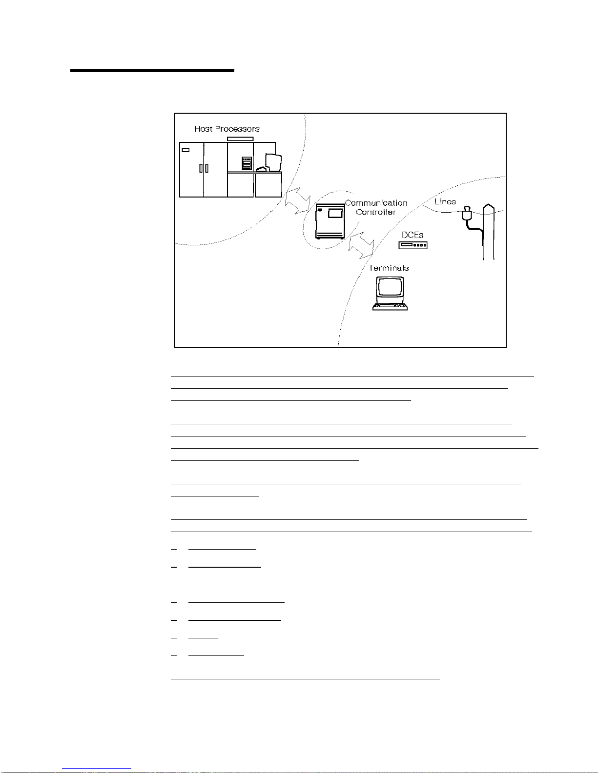
In today's communication networks, the communication controllers save much data
processing power by handling sophisticated functions to control the data flow
between host processors and the network of terminals.
The IBM communication controllers are intelligent and multifunctional systems
dedicated to communications. They are able to serve as nodes (data processing
center nodes, distributed data processing center nodes, concentrator access nodes,
intermediate routing nodes) in the network.
Intelligent
network, like routes.
Multifunctional
facilities stored in the IBM communication controllers to perform functions such as:
Route selection
Multihost access
Data switching
Network management
Message sequencing
Pacing
Flow control.
refers to their ability to dynamically alter certain characteristics of the
refers to their capability of taking advantage of the SNA software
in addition to the physical transmission and reception of data.
Copyright IBM Corp. 1989, 1991 1-1
Page 14

The IBM communication controllers run under control of the Network Control
Program (NCP) stored in their own storage and generated in the host using the
System Support Programs (SSP).
1-2 IBM 3745 Models 130, 150, 170: Introduction
Page 15
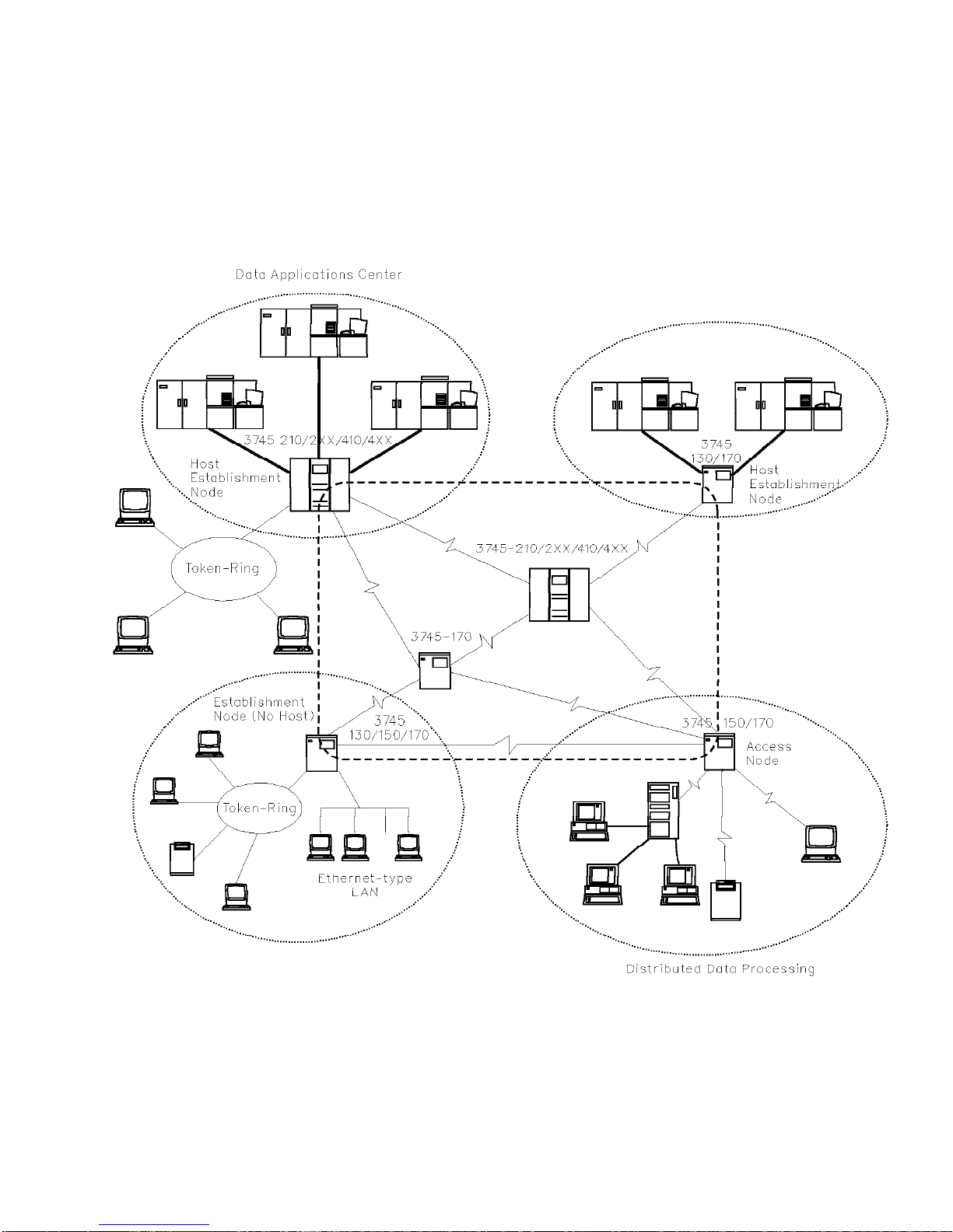
IBM 3745 Communication Controllers in a Typical Network
Chapter 1. Highlights 1-3
Page 16
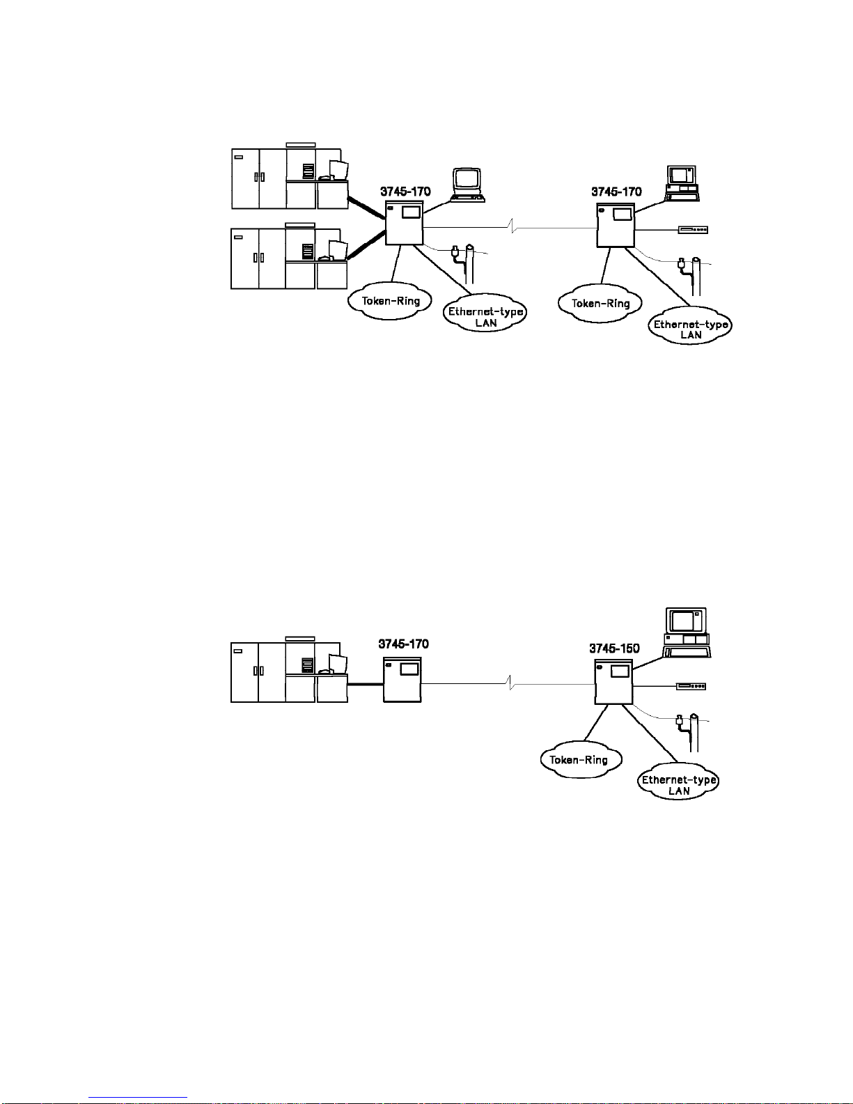
3745 Model 170 Environment
4 Channel adapters
96 Low/medium-speed lines
32 Integrated DCEs (Modems/DSUs)
4 High-speed lines (2 active at a time)
2 Token-rings
| 4 Ethernet-type LANs
|
|
| Program,
NOTE:
All the above connection capabilities might not be present at the same
time as some items are mutually exclusive (see
GA33-0093).
3745 Model 150 Environment
32 Low/medium-speed lines
16 Integrated DCEs (Modems/DSUs)
2 High-speed lines (1 active at a time)
2 Token-rings
| 2 Ethernet-type LANs
IBM 3745 Configuration
NOTE:
All the above connection capabilities might not be present at the same
time as some items are mutually exclusive (see
Program,
1-4 IBM 3745 Models 130, 150, 170: Introduction
IBM 3745 Configuration
GA33-0093).
Page 17
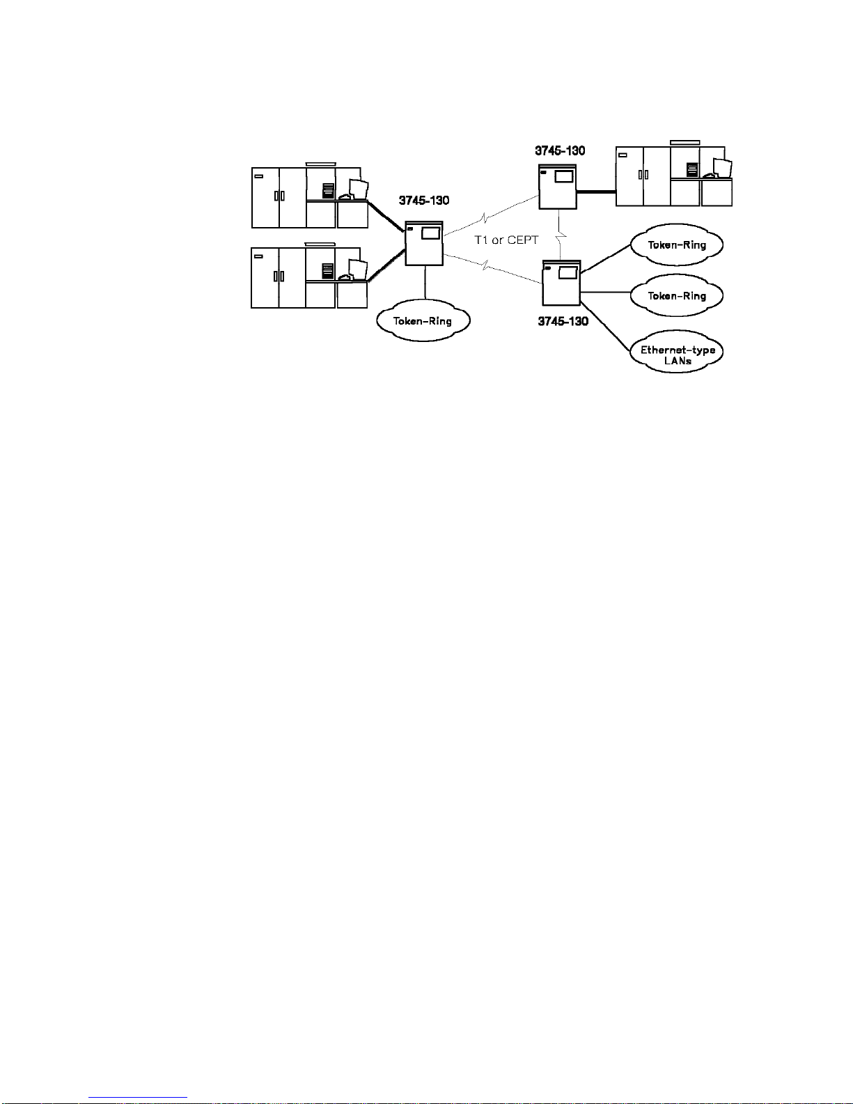
3745 Model 130 Environment
4 Channel adapters
4 High-speed lines (2 active at a time)
4 Token-rings
| 4 Ethernet-type LANs
NOTE:
All the above connection capabilities might not be present at the same
time as some items are mutually exclusive (see
Program,
GA33-0093).
IBM 3745 Configuration
Chapter 1. Highlights 1-5
Page 18

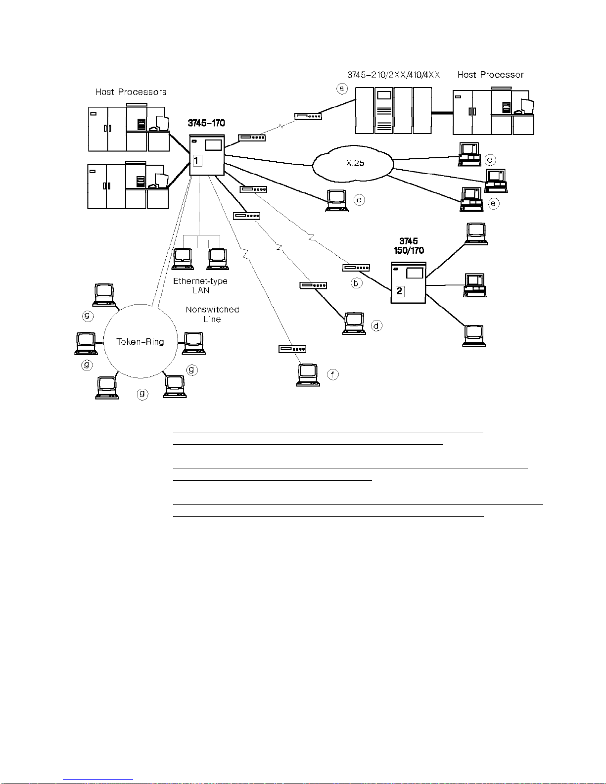
IBM 3745-130/150/170 Communication Controller Connectivity
The following figure shows that, a 3745-130/150/170 can be:
| g
|
1 Channel-attached
2 Link-attached
(via a channel adapter) to one or more hosts.
(via telecommunication facilities) to a host through another IBM
communication controller (allowing a 3745-130/150/170 to be used as a
remote concentrator).
Then, the 3745-130/150/170 allows simultaneous connection to:
a
Other IBM communication controllers, via high-speed lines (such as T1 or
CEPT) and their associated DCEs.
b
Other IBM communication controllers, via medium or high-speed lines and
their associated DCEs.
c
Local clusters and terminals, directly attached without DCE.
d
Remote clusters and terminals, via stand-alone DCEs and telecommunication
facilities (switched or nonswitched).
e
Remote communication controllers, clusters, and terminals, via X.25 public
data networks.
f
Remote communication controllers, clusters, and terminals, via integrated
DCEs and 4-wire nonswitched telecommunication facilities or DDS network in
U.S.A.
Communication controllers, clusters, and terminals on IBM token-ring local
area networks or on Ethernet-type local area networks.
1-6 IBM 3745 Models 130, 150, 170: Introduction
Page 19
These capabilities allow network growth by permitting combinations of
3745-130/150/170 with other IBM communication controllers.
|
|
Different combinations of channel, transmission line, Ethernet-type network, and
token-ring network attachments are possible.
The modularity of the 3745-130/150/170 hardware and control programs provides a
high degree of flexibility in configuring and reconfiguring the networks.
The host processors connected to a 3745-130/150/170 can be the IBM 4341, 4361,
| 4381, 937X, 308X, 3090*, or ES/9000* Processors.
Chapter 1. Highlights 1-7
Page 20

IBM 3745 Models 130, 150, and 170
The 3745 Communication Controller Models 130, 150, and 170 complement the
|
|
IBM 3745 communication controller family and are compatible with IBM
communication controllers: 3705, 3725, 3720, 3745 models 210, 310, 410, and 610.
| 3745
| 3745
| 3745
| 3745
| 3745
| 3745
| 3745
| 130
| 150
| 170
| 210
| 310
| 410
| 610
| CCU
| 1
| 1
| 1
| 1
| 1
| 2
| 2
| Main storage (MB)
| 8
| 8
| 8
| 8
| 8
| 2 x 8
| 2 x 8
| Channel adapters
| 4
| 0
| 4
| 16
| 16
| 16
| 16
| Low/medium-speed lines
| 0
| 32
| 96
| 896
| 896
| 896
| 896
| Integrated DCEs (Modems/DSUs)
| 0
| 16
| 32
| 416
| 416
| 416
| 416
| High-speed lines
| 4*
| 2*
| 4*
| 16*
| 16*
| 16*
| 16*
| Token-rings
| 4
| 2
| 2
| 8
| 8
| 8
| 8
| Ethernet-type LANs
| 4
| 2
| 4
| 16
| 16
| 16
| 16
* Half are active at one time
NOTE:
time as some items are mutually exclusive (see
Program,
All the above connection capabilities might not be present at the same
IBM 3745 Configuration
GA33-0093).
1-8 IBM 3745 Models 130, 150, 170: Introduction
Page 21

Chapter 2. IBM 3745 Models 130, 150, and 170 Highlights
|
Availability
Like the IBM 3745 models 210, 310, 410, and 610 the IBM 3745 models 130, 150,
and 170 contribute to improved
of the network. IBM 3745 models 130, 150, and 170 also provide a high degree of
reliability and an advantageous
The IBM 3745 models 130, 150, and 170 offers increased availability
characteristics. Some of them enhance the operational aspect of managing local or
remote controllers. Also, the LSI technology ensures higher reliability.
The main characteristics contributing to high availability are:
Hot pluggability, which allows the user to remove, add, or replace a LIC while
the 3745 is operational. Plugging or unplugging does not affect the other line
operation.
External cable plugging/unplugging by the user.
Concurrent diagnostics. Most components and subsystems can be diagnosed
while the 3745 continues to run.
Remote support facility.
The following capabilities also enhance the availability of the controller operation:
Scheduled power on.
availability, performance, usability,
price/performance ratio
.
and
connectivity
| Concurrent and scheduled IPL in all network communication controller nodes
| (Timed IPL function)
Up to two control program load modules stored on the communication
controller's integrated hard disk. This allows fast and nondisruptive control
program loading.
One central control unit (CCU) dump module, also on the integrated hard disk.
This allows fast dumping after CCU failure.
Remote access to the maintenance and operator subsystem (MOSS).
Improved error messages and error checking and correction (ECC).
Performance
The system performance of a 3745 model 130, 150, or 170 is higher than for a
3720 or a 3725.
The main elements contributing to higher performance are:
Increased CCU performance: about 1.5 times the 3725; about 4 times the
3720.
"Cache" high-speed buffer (HSB) with a capacity of 32KB (KB equals
1024 bytes). This lets the transfer of instructions and data from main storage
match the CCU cycle time.
Main storage of 4 or 8MB (MB equals 1 048 576 bytes).
Copyright IBM Corp. 1989, 1991 2-1
Page 22

Configuration of channel adapters (CAs) for a maximum of four host
connections, optionally with data streaming protocol.
High-performance transmission subsystem (HPTSS) with SDLC high-speed
lines (1.5 Mbps with T1 clear channel or 2 Mbps with CEPT clear channel).
Direct memory access (DMA) with DMA bus, allowing the high-performance
transmission subsystem (HPTSS) to work efficiently by transferring data directly
to or from main storage.
Selective scanning, ensuring increased flexibility for LIC configurations and
reduced scanning load. Only the LICs with active connected lines are scanned.
Usability
The 3745 design contains a user access area. Access to such areas enables the
user to install, remove, or repair devices (line interface couplers and cables) while
the controller is operating (hot pluggability). The LIC can be plugged or unplugged
without disturbing the scanner or impairing the network.
| At 3745 initial installation, IBM service will do the standard cable installation,
| connection, and testing. IBM service will also install LIC MES cables at user
| request. After 3745 initial installation, the user can install and connect external
| cables, except channel cables.
| Network IPL operations are now easier with a shorter execution time. The timed
| IPL function allows restarting a large network, or part of it, including several nodes,
| at a scheduled time, from one port of this network. See also “Automatic Control
| Program Load” on page 3-4.
Enhanced load module operation allows the operator to transfer and save the
control program load modules on the hard disk. This operation and the replacement
or purge of a load module already stored on disk are executed in a nondisruptive
manner. The controller will continue to run and the currently-running load module
will not be affected. The user can select the load module to be used for controller
| initialization from the host or from the 3745 console. The rename load module
| function allows renaming of the MOSS disk active module and the standby module.
| This renaming can be initiated from any VTAM console in the network.
More usability is offered for channel adapter control. The channel adapters can be
enabled or disabled from the 3745 operator console at any time. Also, the native
and emulated subchannel address range can be set from the 3745 operator
console. This capability avoids the need to use hardware jumpers to set these
options.
Increased usability is available for setting the speed of direct-attached lines. The
MOSS uses the speed defined in the control program load module.
Enhanced MOSS functions provide the user with improved tools for error detection
and failure isolation. Problem determination facilities and controller services under
user control contribute to better serviceability and usability. The menu design of
the MOSS functions at the 3745 console eases using the MOSS functions.
2-2 IBM 3745 Models 130, 150, 170: Introduction
Page 23

Serviceability
Error handling is improved by:
Tracking of all detected incidents
Box event records (BERs), relating to hardware or microcode, stored on
controller hard disk
Automatic BER analysis (autoBER)
Alarms
Generic alerts via the NetView* program
Controller resource reactivation, for example: automatic control program
loading, MOSS and scanner microcode loading
Line wrap test
Internal scanner interface trace (SIT) trace stacked on controller hard disk
Concurrent NCP and scanner dumps on controller hard disk
Continued operation avoiding controller shutdown in various failure situations.
Connectivity
The error-handling procedures and improved problem determination lead to better
serviceability.
The architecture of the 3745 models 130, 150, and 170 has been designed to cope
with constant changes in communication facilities:
Rapid network growth
Added complexity
New applications
Additional communication facilities.
See “IBM 3745 Models 130, 150, and 170” on page 1-8 and Connectivity on page
1-6 for detailed channel and communication interface capabilities.
The configuration initially defined at installation (generation) can be upgraded at
any time to meet growing network requirements.
Chapter 2. IBM 3745 Models 130, 150, and 170 Highlights 2-3
Page 24

2-4 IBM 3745 Models 130, 150, 170: Introduction
Page 25
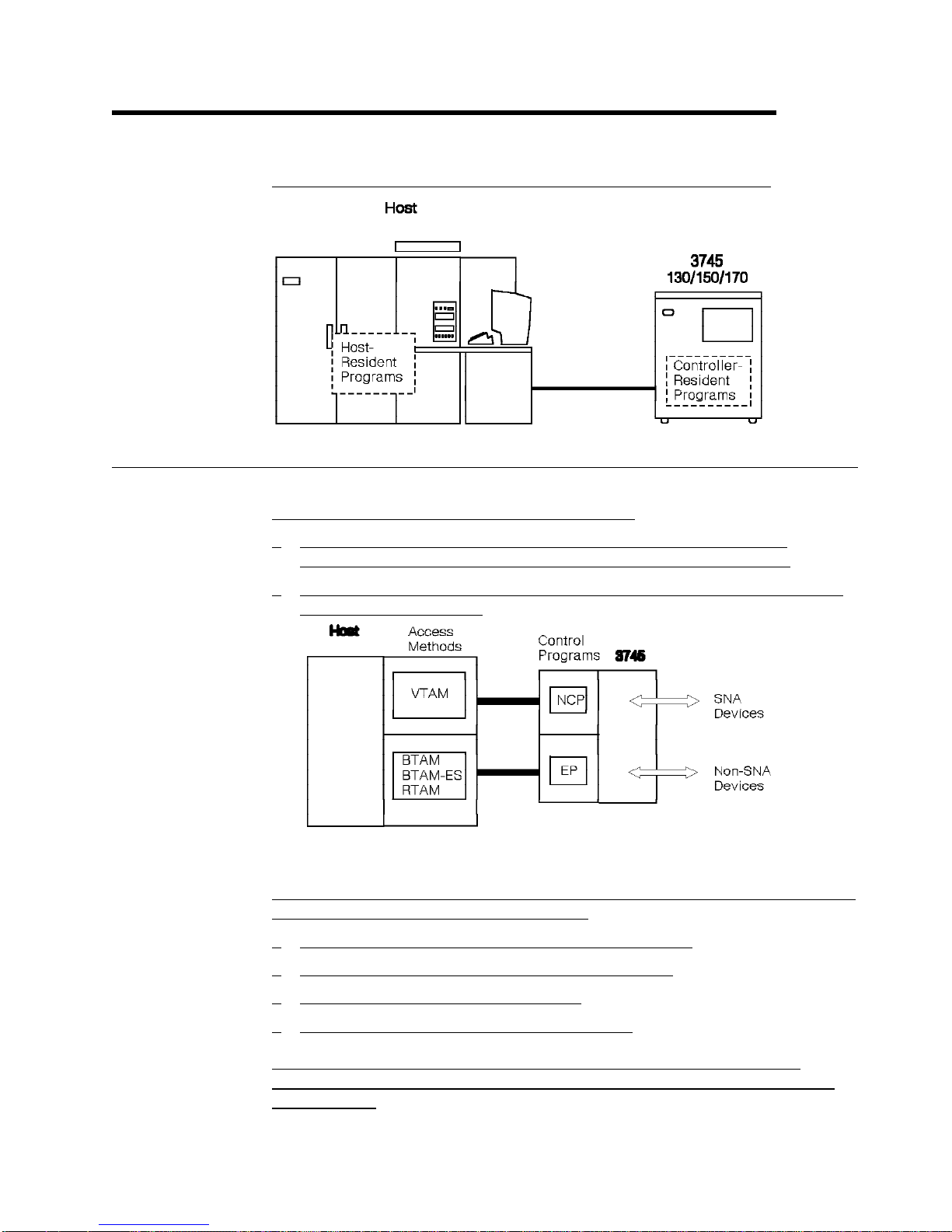
Chapter 3. Program Support and Network Management
The 3745 operates under the control of various IBM licensed programs:
Controller-Resident Programs
The 3745 runs under control of one of the following:
Advanced Communications Function for the Network Control Program
(ACF/NCP), abbreviated NCP in this book, to support SNA devices, or
Emulation Program (EP) in partitioned emulation programming (PEP) mode to
support non-SNA devices.
Network Control Program (NCP)
NCP Version 5 provides major capabilities for SNA networks with synchronous data
link control (SDLC). The 3745 operates with:
NCP Version 5 Release 2.1 under MVS, VM, and VSE*.
NCP Version 5 Release 3 under MVS, VM, and VSE.
NCP Version 5 Release 3.1 under MVS.
NCP Version 5 Release 4 under MVS, and VM.
|
|
|
Copyright IBM Corp. 1989, 1991 3-1
NCP Version 5 Release 4 or any previous NCP releases do not support the
Ethernet LAN adapter. The functions support will be provided with a then current
NCP and SSP.
Page 26

Start-stop and binary synchronous terminals can be migrated to a 3745 with the
IBM Network Terminal Option (NTO) program. For start-stop protocols, NCP
supports a variety of transmission codes including ASCII, EBCDIC, EBCD, and
BCD. Further, it supports a correspondence code for which it provides translation
from and to EBCDIC. For the BSC protocol, this support and translation operation
is performed by the scanners.
NCP provides the controller flexibility to meet the demands of an expanding
network. It works with the host access method to control networks, from the
simplest single-domain network with a single controller, to complex multiple-domain
networks using the Advanced Communications Function, in accordance with the
concepts of SNA.
NCP includes the following functions:
Token-ring interface
Airline Line Control Interface (ALCI) (optional/feature).
NCP coexists with the following IBM licensed programs:
Network Routing Facility (NRF)
Network Terminal Option (NTO)
Non-SNA Interconnection (NSI)
X.25 NCP Packet Switching Interface (NPSI)
X.25 SNA Interconnection (XI)
X.21 Short Hold Mode/Multiple Port Sharing (X.21 SH/MPS).
Partitioned Emulation Programming Extension
The partitioned emulation programming (PEP) extension of NCP allows the NCP
and the EP to coexist in the same 3745. PEP lets NCP operate certain lines in
network control mode while operating others in emulation mode.
PEP can run only in a channel-attached controller. Channel attachment must be a
byte multiplexer channel, where one emulated subchannel address is specified per
EP line. Buffer chaining process does not support EP traffic under PEP.
PEP emulates most of the functions of the IBM 2701 Data Adapter Unit, IBM 2702
Transmission Control, or IBM 2703 Transmission Control and can communicate
with various access methods running in the host. Most programs written for these
machines can operate in a 3745 without modification. However, programs that
involve timing or special hardware considerations may have to be changed.
Generating and Loading the Control Program
We use SSP elsewhere on the owning host to generate the control program load
module (up to 6MB) and to load it into the controller storage. The control program
for the controller is generated from standard program modules of the NCP library
using the NCP/EP definition facility (NDF). The control program must reflect the
required controller configuration. Several control programs can be generated to
handle different subsets of lines attached to the same controller.
3-2 IBM 3745 Models 130, 150, 170: Introduction
Page 27
Multiple Load Module
The network operator can transfer and save either one or two CCU load modules
(up to 6MB per load module) on the integrated hard disk. Either load module can
be selected for loading at controller initialization.
When initiating a control program load request at the host, the network operator
can designate the disk-resident load module that will be
control program loading and dump.
| The network operator can change the external name of a communication controller
| load module on the MOSS disk. The rename load module function is started by a
| modified VTAM command (load command).
A control program load request that is initiated automatically by MOSS uses the
load module last loaded in the CCU if it was saved to the disk or loaded from the
disk during IPL. This load module is displayed specified as the
at the 3745 console (see “Disk IPL Information” on page 4-32).
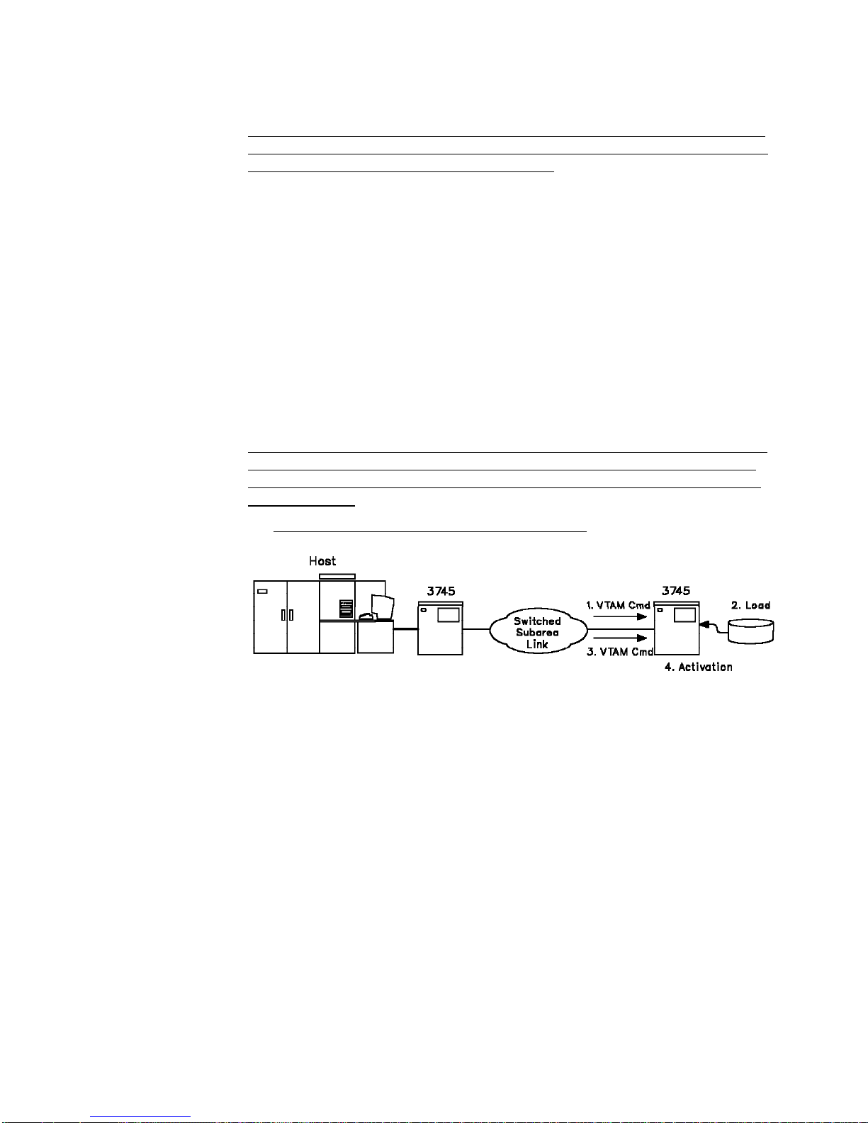
Remote Loading and Activation
For a remote 3745 connected to a channel-attached 3745 via a switched subarea
link (NTRI, X.21 switched or X.25 leased and switched), the remote loading and
activation capability allows the host (through VTAM commands) to load and start
the remote NCP:
active
for later automatic
active
load module
From the remote disk to the remote CCU storage
As the loading of the NCP load module on the remote 3745 hard disk is done via a
1MB diskette written from the local 3745 hard disk, this option is used when the
NCP load module size does not exceed 1MB. (See “MOSS Functions” on
page 4-27 for local disk to diskette and remote diskette to disk NCP transfer):
.
Chapter 3. Program Support and Network Management 3-3
Page 28
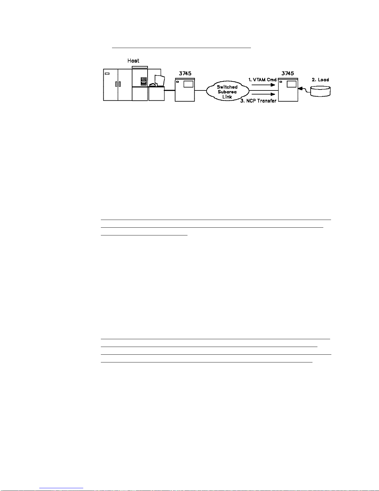
From the host storage to the remote CCU storage
This option is used when the NCP load module size exceeds 1MB and cannot be
transported from the host to the remote 3745 via a 1MB diskette.
.
In this case a
is less than 1MB thus fitting onto a diskette. It is then transferred from this diskette
to the remote 3745 hard disk. On receipt of appropriate VTAM commands, this
reduced load module is loaded from the remote disk to the remote CCU storage
and there, handles the transfer of the complete NCP from the host storage to the
remote 3745 storage via the switched subarea link. (See “MOSS Functions” on
page 4-27 for local disk to diskette and remote diskette to disk transfer).
reduced NCP load module
Automatic Control Program Load
VTAM and the 3745 MOSS allow the automatic IPL and dump capabilities. For an
automatic IPL from the controller disk, the network operator must have specified
this option during NCP loading.
This capability can also be selected for any IPL operation. In that case:
The CCU initialization automatically uses the active disk-resident load module
after power-on or in case of CCU failure.
After an NCP abend or a hard CCU failure, there is an automatic dump of the
controller storage before the control program reloading. The dump is saved on
the controller disk. MOSS capabilities include transfer of the full or partial
dump, printing at the host, and purge of the dump.
See also “Automatic IPL and Dump” on page 4-29.
is generated in the host, the size of which
|
|
|
|
|
| The new loaded NCP module can be:
| A new module sent from VTAM
| A standby module already loaded on the MOSS disk.
Timed IPL
The timed IPL function allows controllers in a large network to automatically reload
at a scheduled time. The operator can send an IPL request to any part of the
network, from a VTAM console to define the IPL time. At the prescribed time all of
the selected controllers will automatically reload without any operator action.
3-4 IBM 3745 Models 130, 150, 170: Introduction
Page 29

Coexistence and Migration
The NCP Version 5 operating the 3745 can coexist in a given network with other
IBM communication controllers with NCP levels described in the table below:
| IBM 3705| IBM 3725| IBM 3720| IBM 3745
| IBM 3745
| IBM 3745
| 210/410
| 130/150/170
| 310/610
| NCP V2
| NCP V2
| NCP V4 R1
| NCP V5 R2.1
| NCP V5 R2.1
| NCP V5 R4
| NCP V3
| NCP V3
| NCP V4 R2
| NCP V5 R3
| NCP V5 R3
| NCP V4 R1
| NCP V4 Subset
| NCP V5 R3.1
| NCP V5 R3.1
| NCP V4 R2
| NCP V5 R1
| NCP V5 R4
| NCP V5 R4
| NCP V4 R3
| NCP V5 R2
| NCP V4 R3.1
| NCP V5 R2.1
| NCP V5 R3
NCP allows 3745 to support networks based on the earlier IBM 2701 Data Adapter
Unit, IBM 2702 Transmission Control, or IBM 2703 Transmission Control, and
|
|
|
|
networks in which these units are emulated on a 3720 or on a 3725 via an
Emulation Program (EP 9). PEP permits migration from the 2701, 2702, 2703, and
from IBM 3704, 3705, 3720, and 3725 communication controllers that run EP. The
3745 Models 310 and 610 have no EP stand-alone support.
|
|
Stand-alone Emulation Program Release 8 operates in 3745 Model 210 or Model
410. The 3745 Models 310 and 610 have no EP stand-alone support.
Communication controllers configured with EP only, IBM Network Extension Facility
(NEF), or IBM Non-SNA Interconnection (NSI) can coexist with the 3745 in the
same network.
The IBM Transaction Processing Facility host program is supported by NCP
Version 5 Release 3 in the 3745.
The 3745 offers a path for conversion from existing systems and for continuing
growth. A system designed for the IBM 3725 or 3720 may be applied to the 3745
after regeneration of the control program. The control program resource definition
input to the 3725 or 3720 program generation can be used with some modifications
to statements (if the controller has the same line configuration).
Chapter 3. Program Support and Network Management 3-5
Page 30

Host-Resident Programs
Operating Systems
MVS
MVS/XA*
MVS/ESA*
VM/SP
VM/SP HPO
VM/XA*
VSE/AF
VSE/SP.
Access Methods
Normal Mode:
|
|
Virtual Telecommunications Access Method (VTAM) Version 3 Release 1.1,
Release 1.2, Release 2, Release 3, Release 4, or Release 4.1.
Emulation Mode:
Basic telecommunications access method (BTAM)
BTAM extended storage (BTAM-ES)
Remote terminal access method (RTAM).
System Support Programs
Advanced Communications Function for System Support Programs (SSP)
|
|
|
Version 3 Release 4.1 or Release 5 in MVS, VM, or VSE environments,
Version 3 Release 5.1 in MVS environment,
Version 3 Release 6 in MVS and VM environments.
SSP is used to generate the 3745 control program.
In addition, SSP provides utilities for loading, dumping, and tracing the 3745 control
program. It also supports:
Dump transfer of the 3745 storage to the host.
Dump printing at the host.
3745 disk file transfer to the host.
Network Management
The 3745 network management is supported by the NetView program Releases 2
and 3. By monitoring and managing the controller and its resources, and by
diagnosing problems, this program contributes to the optimization of the 3745.
For example:
3-6 IBM 3745 Models 130, 150, 170: Introduction
Page 31

A command facility, which lets the user control, record, and automate various
operator tasks. It can be used as an operator's interface to VTAM in a data
communication network.
A session monitor, which enables the user to examine, from a central control
point, information related to the SNA network and to identify network problems.
A hardware monitor, which helps the user to get problem determination
information that is generated at resources that are either link-attached or
channel-attached to the host system.
As a cohesive set of SNA host network management services, the NetView
program offers:
Consistency and usability in its support for network management
Easy installation procedure
Device support
Operator usability.
The 3745 supports:
Link Problem Determination Aid (LPDA*) facilities provided by IBM DCEs.
NetView Performance Monitor (NPM) under VM and MVS.
Chapter 3. Program Support and Network Management 3-7
Page 32

3-8 IBM 3745 Models 130, 150, 170: Introduction
Page 33

Chapter 4. Controller Description
The 3745-130/150/170 consists of three main functional areas:
The following is a functional description of the main components and available
features of the 3745-130/150/170.
The overall data flow of a maximum 3745-130/150/170 configuration is shown on
page 6-6.
Copyright IBM Corp. 1989, 1991 4-1
Page 34

Control Subsystem
The control subsystem contains:
The central control unit (CCU), with its associated CACHE high-speed buffer
(HSB).
The main storage.
The storage control, equipped with a direct memory access (DMA).
The input/output control bus (IOC bus).
The DMA bus.
The MOSS input/output control bus (MIOC bus).
The channel adapters, possibly associated with two-processor switches (TPS).
Central Control Unit
The CCU can be initialized by loading the control program through a host channel
or a communication link, or from the controller hard disk. Data transfer between
the CCU and the main storage is achieved by the storage control and enhanced by
the high-speed buffer. Data is also transmitted directly between the main storage
and the high-speed line adapters via the DMA. The CCU utilization including cycle
| stealing is measured by a cycle utilization counter. The instruction set is similar to
| that of the IBM 3745-210/310/410/610.
For details, see
SA33-0102
IBM 3745 Communication Controller: Principles of Operation,
.
4-2 IBM 3745 Models 130, 150, 170: Introduction
Page 35

High-Speed Buffer
The CACHE HSB is packaged with the CCU and has a capacity of 32KB. It
connects the CCU and the storage control and DMA. Data and instructions
transferred from the main storage at a slower rate are buffered in the high-speed
buffer and provided to the CCU at the CCU cycle rate. Thus, the CCU is not
slowed down by the main storage and can run at full speed.
Main Storage
The main storage is available in two sizes of 4 or 8MB.
Storage Control and DMA
The storage control allocates the main storage access and controls the data
transfer between each controller component and the main storage. The storage
control is equipped with enhanced error checking and correction (ECC). The ECC
enables the correction of a double-bit hard error, and the detection and correction
of a triple-bit error.
| The DMA receives the data transfer requests from one or two very high-speed lines
| or Ethernet LAN lines. The data transfer to the main storage is achieved by cycle
stealing. DMA takes full advantage of the storage speed during data burst
| transfers from the high-speed scanners (HSSs) or from the Ethernet LAN adapters
| (ELAs).
Input/Output Control Bus
The IOC bus allows the data, address, and control information to be exchanged
between the CCU work registers and the channel and line adapters.
DMA Bus
| The DMA bus allows data transfer only (in cycle steal) between the CCU storage
| and the high-speed scanners, or the Ethernet LAN adapters.
MIOC Bus
The MIOC bus provides a dedicated connection between the CCU work registers
and the MOSS registers.
Channel Adapters
There are two types of channel adapters, the regular channel adapter (CA) and the
buffer chaining channel adapter (BCCA). Both types will be called channel adapters
(CAs) in this book unless otherwise specified.
A maximum of four channel adapters (CAs) provide connection between four hosts
and the CCU via the IOC bus. Optionally, CAs can be equipped with a
two-processor switch (TPS) feature in that case, the maximum number of CAs is
two.
Each channel adapter is equipped with a microprocessor. The channel adapters
| attach the CCU to the host data channels. The hosts supported include the IBM
| 4341, 4361, 4381, 937X, 308X, 3090, and ES/9000 Processors. Host channels are
byte multiplexer, block multiplexer, or selector channels. Further, the IBM 3044
Fiber-Optic Channel Extender Link can also be supported when operating in
high-speed data transfer or in direct-current interlock mode.
The 3745 channel adapters support data transfer in three modes:
Chapter 4. Controller Description 4-3
Page 36

Direct-current interlock (DCI)
High-speed transfer
Data streaming.
Depending on the programming support, CAs can be operated:
In native mode under NCP control. Only one channel address is used to
transmit all data to a host.
In partitioned mode under PEP control. PEP operates certain lines in native
mode, while operating other lines in emulation mode (EP mode). One
subchannel address is required per line. Channel attachment is
byte-multiplexed.
CAs also support I/O error alert. They use self-checking routines. CA features and
parameters are defined at installation time and saved in the MOSS. They are set
up by the MOSS at each initial program load (IPL) afterwards. Channel adapters
can be enabled and disabled by the operator from the attached operator console at
any time without having to log onto the console.
The channel interface cable allows attachment of the 3745 to a host located at up
to 61 m (200 ft) in direct-current interlock or high-speed transfer mode.
Channel Adapter with Data Streaming
The data streaming feature makes it possible to reach a high-speed data rate for a
host located at up to 122 m (400 ft) from the controller. Data can be transferred in
synchronous mode. The instantaneous data rate can reach a maximum speed of
3MB per second.
| Channel adapter with data streaming is supported by the IBM 937X, 3090, and
| ES/9000 Processors. The host connection can only be a block multiplexer channel.
The channel extenders are not supported.
Buffer Chaining Channel Adapter
The buffer chaining process makes it possible to increase high speed data rate for
a host and provides higher channel efficiency than data streaming. Data can be
transferred in synchronous mode. Buffer chaining process is only supported by
channel adapter of the BCCA type.
The buffer chaining process is available under NCP or PEP control. The buffer
chaining channel adapter supports NCP only. The EP traffic under PEP is not
supported. The host connection can only be a block multiplexer channel. When
buffer chaining process is not set, the buffer chaining channel adapter works in
data streaming mode. The channel extenders are not supported.
Two-Processor Switch
In addition to the basic interface (A), a two-processor switch (TPS) provides an
additional channel interface, called interface B, to a channel adapter. The two
interfaces can connect to the same host or to different hosts.
MOSS commands issued at the console allow the user to enable, through a
two-processor switch, either one interface (A or B) or both interfaces (A and B).
4-4 IBM 3745 Models 130, 150, 170: Introduction
Page 37

1. Only one interface (A or B) enabled:
The host attached to that interface activates the channel as required by the
application.
2. Both interfaces (A and B) enabled:
Both interfaces A and B are connected to two channels of the
same
host.
Both interfaces cannot be active simultaneously, and the host is responsible for
activating them alternately and dynamically. This maximizes the availability of
the host connections.
| The operations to activate a two processor switch mode are described in the
|
IBM 3745 Communication Controller: Advanced Operations Guide,
SA33-0097.
Chapter 4. Controller Description 4-5
Page 38

Communication Subsystem
|
|
Four types of line connection are used to connect data communication lines:
The transmission subsystem (TSS)
The high-performance transmission subsystem (HPTSS)
The Ethernet-type LAN subsystem (ESS)
The token-ring subsystem (TRSS).
4-6 IBM 3745 Models 130, 150, 170: Introduction
Page 39

Transmission Subsystem (TSS)
The TSS consists of:
Up to six low-speed scanners (LSSs) or
|
Up to four low-speed scanners (LSSs) if two HSSs or ELAs are installed.
And:
Up to four LIC bases (LIBs).
Note: A LIB is functionally equivalent to a LIC unit (LIU) of the
| 3745-210/310/410/610.
Chapter 4. Controller Description 4-7
Page 40

Low-Speed Scanner
A low-speed scanner consists of a communication scanner processor (CSP)
associated to a front-end scanner low-speed (FESL).
Communication Scanner Processor
The 3745 uses a microprocessor-based communication scanner. The CSP
supports multiple line protocols, and provides character buffering and cycle steal
data transfer into main storage. The CSP also does other repetitive operations
such as ASCII/EBCDIC translation for BSC lines.
Front-End Scanner Low-Speed
The FESL provides 'bit service' (serialization/deserialization) and 'line service'
(supports link protocols and line interfaces).
Serial Link
The serial interface link between the FESL and LICs provides an easier adaptation
to configuration changes. The twisted-pair interface eliminates the fixed positional
relationship between scanner and LIC. The flexible nature of the serial link allows
the CSP and the connecting LICs to be in any of their positions within the 3745.
Depending on the model, the 3745 can have scanners and LICs independently
added to support performance or connectivity requirements.
This design provides effective use of scanner resource.
Selective Scanning
|
4-8 IBM 3745 Models 130, 150, 170: Introduction
As in the 3745-210/310/410/610, a new logical addressing technique allows
scanning of only the activated lines. When all the lines of a LIC are deactivated, it
is removed from the scanning sequence (except for X.21 lines). This increases the
number of LICs that can be attached to the CSP. It is possible to exceed 100%
line weight when configuring the 3745. The only constraint is that the weight of
activated
lines must not exceed 100%.
Page 41

Logical addressing improves the flexibility of LIC attachment. LICs can be placed
anywhere without regard to the scanning sequence or LIC weight. High-speed
LICs can come before or after low-speed LICs and there can be open LIC
positions.
Selective scanning allows an LSS to run multiple line configurations at different
times. It also simplifies configuration and installation of LICs attaching
higher-speed lines (256 kbps) with other LICs.
Notes:
1. It is the user's responsibility to ensure that the currently-active line configuration
does not overload the scanner processing capability. See the explanation of
line weights on page 4-11 and also in the
GA33-0093.
2. A scanner cannot recognize a change in line configuration, and is likely to
become overloaded. It is necessary that an active configuration is completely
deactivated before another configuration is activated, for example, changing
from night operation to day operation.
IBM 3745 Configuration Program,
Chapter 4. Controller Description 4-9
Page 42

LIC Base (LIB)
There are up to four LIC bases (LIBs).
Each LIB houses:
One multiplexer (MUX) and
Up to eight line interface couplers (LICs).
The figure below shows a maximum configuration for a 3745-170.
4-10 IBM 3745 Models 130, 150, 170: Introduction
Page 43

Line Interface Couplers (LICs)
There are six types of LIC, namely:
LIC1, LIC3, LIC4A
and
LIC4B
for attaching:
– Local direct-attached DTEs (not attached through DCEs)
– Remote DTEs attached via stand-alone DCEs and telecommunication
facilities.
An internal clock function (ICF) is available on these LICs to provide clocking
signals to nonclocked DTEs or DCEs (see Appendix A for details).
LIC5
and
LIC6
, both housing integrated DCEs, providing direct access to the
telecommunication facilities for attaching remote terminals.
The clocking of lines attached to these LICs is provided by the integrated DCEs
(see Appendix A for details).
LIC Weights
The weight of a line is a value (0.4 through 100) that represents the percentage of
scanner occupation. The weight of a line depends on its speed (bps), the protocol
(SS, BSC, SDLC), the mode of transmission (HDX, FDX), and the characters code
(ASCII,
EBCDIC, ...). The total weight of active lines connected to a scanner must be
equal to or less than 100.
LIC User Access
User access to LICs eases upgrading of the 3745 and repair in case of failure. Hot
pluggability allows plugging and unplugging when the 3745 is in operation. Thus,
LIC replacement, addition, or removal does not disturb the scanner nor impair the
network.
Then, the LICs have been designed to accept snap-on cables: this allows quick
cable attachment of telecommunication lines.
Chapter 4. Controller Description 4-11
Page 44

LIC Characteristics
Following are the main characteristics of the LICs 1 through 6.
Speed : Up to 19.2 kbps
Protocol : Start-Stop, BSC, SDLC
Interface : CCITT V.24 and V.25 (EIA 232D and 366), CCITT V.25 bis (see
Note),
CCITT X.20 bis and X.21 bis
Number of LIC1s per scanner: Up to 8.
Note:
CCITT Recommendation
V.25 BIS
for switched connections
allows call establishment and data transfer to take place over
the same port. This eliminates the need for a second physical
port (on a LIC1) and its associated Automatic Calling Unit
(ACU). The 3745 supports the following CCITT
V.25 BIS
options:
Call establishment in SDLC or start-stop mode,
Data transmission in SDLC, BSC, or start-stop mode,
Call request with number to be dialed (CRN command),
optionally accompanied by the identification number of the
caller (CRI command),
"Call Failure Indication" and its associated two-character
failure condition (if provided by the DCE),
"Delayed Call Indication" (if provided by the DCE) and its
associated parameter (up to three characters specifying the
minimum time before next call attempt),
4-12 IBM 3745 Models 130, 150, 170: Introduction
"Invalid Indication" from the DCE (a command sent to the
DCE cannot be processed),
Auto-answer controlled by the 3745 and based on the
"calling indicator" circuit.
Page 45

Speed : Up to 256 kbps
Protocol : BSC, SDLC
Interface : CCITT V.35
┌───────────┬────────────┬───────────┐
│ <32 kbps │ 32 to 64 │ >64 kbps │
Number of LIC3s per scanner: ├───────────┼────────────┼───────────┤
| │ 8 │ 4 to 8 │ 1 or 2 │
└───────────┴────────────┴───────────┘
Speed : Up to 9.6 kbps
Protocol : SDLC
Interface : CCITT X.21
Number of LIC4As per scanner: Up to 8.
Chapter 4. Controller Description 4-13
Page 46

Speed : Up to 256 kbps
Protocol : SDLC
Interface : CCITT X.21
┌───────────┬────────────┬───────────┐
│ <32 kbps │ 32 to 64 │ >64 kbps │
Number of LIC4Bs per scanner: ├───────────┼────────────┼───────────┤
| │ 8 │ 4 to 8 │ 1 or 2 │
└───────────┴────────────┴───────────┘
Speed : 4.8, 9.6, or 14.4 kbps
Protocol : BSC, SDLC
Interface : Voice-grade telecommunication network
Number of LIC5s per scanner: Up to 16
Configuration: Point-to-point, multipoint.
The LIC5 integrated DCEs are compatible with the stand-alone and rack-mounted
IBM 586x and 786x DCEs.
4-14 IBM 3745 Models 130, 150, 170: Introduction
Page 47

| Speed: 9.6, 19.2, or 56 kbps.
Protocol : BSC, SDLC
Interface : Digital Data Service Network
Number of LIC6s per scanner:
Speed = 56 kbps : Up to 4
Speed = 19.2 kbps : Up to 8
Speed = 9.6 kbps : Up to 8
Configuration: Point-to-point, Multipoint.
The LIC6 integrated DCE is compatible with the IBM 5822 Model 10 or 18 Data
Service Unit/Channel Service Unit (DSU/CSU).
Notes:
1. LIC5 and LIC6 integrated DCEs can stand poor line conditions or temporary
line problems. For this, the operator can select a slower speed, called the
backup speed. When normal line conditions resume or the line problems are
corrected, the normal transmission speed is set again.
2. LIC5s and LIC6s provide a port and a cable adapter for connection of an
external monitoring equipment.
Chapter 4. Controller Description 4-15
Page 48

Portable Keypad Display
An IBM 5869 Portable Keypad Display, pluggable at LIC5s or LIC6s, is used to:
Configure.
Set operational options.
Display line status.
Invoke manual tests of the integrated DCEs (see Chapter 5, Problem
Determination). Various parameters are stored in a nonvolatile random access
memory (RAM).
Details on LIC5 DCEs can be found in the
Planning Guide,
Details on LIC6 DCEs can be found in the
Operations,
GA33-0122.
GA33-0136.
IBM 786x Modem: Description and
IBM 5822-18 CNM DSU/CSU: Guide to
4-16 IBM 3745 Models 130, 150, 170: Introduction
Page 49

High-Performance Transmission Subsystem (HPTSS)
The HPTSS consists of up to two high-speed scanners (HSSs).
A HSS consists of one communication scanner processors (CSP), associated with
a front-end scanner high-speed (FESH).
Communication Scanner Processor
The HPTSS CSP is the same as the LSS CSP, but is loaded with different
microcode.
The high-speed scanner accepts a clear channel (without channel and subchannel
TDM framing) at speeds up to 1544 megabits per second for T1 and up to 2048
megabits per second for CEPT. The high-speed scanner is used for intermediate
routing node (IRN) support of high-speed line to another communication controller.
This connection must be SDLC, duplex, point-to-point, nonswitched line traffic. This
high-speed scanner can also be used for boundary network node (BNN) support.
The HPTSS supports CCITT V.35 and X.21 interfaces, but only one interface may
be activated at a time (the NCP load module determines which interface is to be
activated).
Front-End Scanner High-Speed
The FESH provides 'bit service' (serialization/deserialization) and 'line service'
(supports link protocols and line interface).
The FESH may interface with:
Network channel terminal equipments (NCTEs)
Data service unit/channel service units (DSU/CSUs)
Limited-distance modems (LDMs)
Chapter 4. Controller Description 4-17
Page 50

Other local direct-attached IBM communication controllers. The maximum
speed is then 1.8 Mbps and the maximum distance is 10 m
(33 ft.) via X.21 interface and 100 m (328 ft.) via a V.35 interface.
For direct-attachment, the FESH provides data clocking (see Appendix A).
Token-Ring Subsystem (TRSS)
The TRSS consists of up to two token-ring adapters (TRAs).
A TRA consists of one token-ring multiplexer (TRM) driving two token-ring interface
couplers (TICs) providing access to two IBM token-ring local area networks (LANs)
operating at speeds of either 4 or 16 Mbps.
Token-Ring Multiplexer (TRM)
The TRM handles operations between the NCP running in the CCU and the two
TICs.
Token-Ring Interface Coupler (TIC)
Each TIC contains a microprocessor operating under control of resident microcode.
The coupler transmits and receives at a speed of 4 or 16 Mbps using protocols
conforming with IEEE 802.5 and ECMA 89 standards. However, the throughput of
the 3745 depends on transaction characteristics, NCP path length, and 3745
utilization. Token-ring devices can be predefined to the system, allowing terminals
to be added or deleted nondisruptively and without having to generate a new NCP
load module.
4-18 IBM 3745 Models 130, 150, 170: Introduction
Page 51

| Ethernet-Type LAN Subsystem (ESS)
|
|
|
The ESS consists of up to two Ethernet LAN adapters (ELAs).
A ELA consists of one communication scanner processor (CSP), associated with an
Ethernet adapter.
| Communication Scanner Processor
| The ESS CSP is the same as the HPTSS CSP, but is loaded with different
| microcode.
| Ethernet Adapter
| The Ethernet adapter supports two transceiver ports connected to Ethernet V2 or
| IEEE 802.3 LAN. Both ports can be active at the same time to the NCP.
| The ELA interface to the external equipment is a IEEE 802.3 15-pin D-type female
| AUI connector. The AUI transceiver cable is not provided by IBM. The ESS uses
| the tail gate location of the corresponding HPTSS.
| The tail gate contains also a DC/DC converter which provides + 12v DC with up to
| 500 mA per port for an external transceiver.
Chapter 4. Controller Description 4-19
Page 52

Maintenance and Operator Subsystem (MOSS)
The MOSS provides:
Powerful procedures for the 3745 initialization and IPL functions
Host-independent product maintenance and rapid isolation and repair of failures
within the controller
Easy problem determination procedures for the operator.
The MOSS also provides:
Automatic IPL and dump operations
Line configuration management
Controller supervision
Controller concurrent diagnostic
Online event recording and error notification including for the integrated DCEs
Problem determination (error in the network including the controller)
Failure isolation and repair (error in the controller)
Remote support facility link management.
The MOSS continuously monitors the status of the communication controller.
Abnormal conditions are analyzed and reported via alarms to the 3745 console(s)
and alerts to the network control console.
Among the components of the communication controller, multiple adapters allow the
MOSS to monitor the status of the CCU, to control the DMA and IOC buses, and to
enable and disable channel adapters.
4-20 IBM 3745 Models 130, 150, 170: Introduction
Page 53

A power control adapter with a dedicated microprocessor monitors the 3745 power.
A file adapter provides MOSS storage control. A 72MB hard disk, in addition to a
1.2MB diskette, provides extensive capacity for file and data storage.
The MOSS interfaces to the control panel indicators and switches. These provide
an alternative method for controlling the primary power subsystem, activating
MOSS functions, and for notifying the operator.
A console adapter allows the 3745 to be controlled from a local console located
within 7 m (23 ft.), or an alternate console located within 120 m (400 ft.), or a
remote console connected via a 1200 bps DCE to the controller. Only one console
may be active at a time. If the remote support facility (RSF) is used, it allows
communication between the MOSS and the IBM RETAIN* system. The RSF
terminal can be used as an operator console and for transferring microcode
patches to the MOSS if required.
MOSS Microprocessor and Storage
The MOSS microprocessor operates independently of the CCU. The microcode is
automatically loaded from disk into the MOSS storage during IML at power-on time.
MOSS storage capacity is 2MB.
MOSS Power Control Adapter
The MOSS power control allows various automatic actions without any operator
intervention, such as:
Reporting power fault to the MOSS
Powering on/off the machine
Reset
Time function
AC line survey
Power diagnostics
Monitoring thermal sensors.
Chapter 4. Controller Description 4-21
Page 54

MOSS Disk/Diskette Drive and Adapter
The diskette drive and disk drive are connected to the MOSS bus via the disk
adapter, and consist of:
An integrated disk drive with one hard disk that provides 72MB.
A diskette drive with removable diskettes. Each diskette provides 1.2MB.
The diskettes contain the MOSS microcode, MOSS files, and diagnostic programs.
At installation time, the diskettes are copied onto the controller integrated disk.
Then, the latter becomes the only disk system used by the MOSS. If the disk fails,
MOSS IML can be performed from the diskette at the control panel.
The hard disk contains the following:
| Scanner microcode (LSS, HSS, ELA)
MOSS microcode
Diagnostic routines
One or two control program load modules
Information relating to the 3745 operation contained in the following files:
– Event log file
– Configuration data file
– Machine level table
– Microcode fix file
– Port swap file
– One control program dump file
– One scanner dump file
– One TIC dump file
– One MOSS dump file
– Trace buffer areas for the scanner.
4-22 IBM 3745 Models 130, 150, 170: Introduction
Page 55

Control Panel
MOSS functions are commonly performed at the console. However, some of them
can, if necessary, be activated at the control panel. For example, the control panel
allows vital functions such as powering on and initializing the controller or stopping
the controller operation (Unit Emergency switch). It also offers some maintenance
procedures.
The control panel is located on the 3745 communication controller. It is always
powered on. When the 3745 is powered off, the control panel display gives
information on power control and service mode.
The ten-digit alphanumeric display shows the operator progress and errors during
initialization. It also displays progress of the MOSS diagnostic programs to IBM
service personnel.
Indicators notify operation and service status. For example, the MOSS Msg and
MOSS Inop indicators prompt the operator to take an appropriate action, as
described in the
Guide, SA33-0096
IBM 3745 Communication Controller: Problem Determination
. MOSS functions and services are started with the keys.
A reference card (packaged in the 3745) lists the MOSS functions and services
available at the control panel.
Chapter 4. Controller Description 4-23
Page 56

Operator Consoles and Remote Support Facility
An operator console is required for:
Installation
Operation
Maintenance.
The 3745 provides attachment for three different types of consoles:
A local
A remote
It also provides attachment for the
console, which is mandatory, and
or an
alternate
console.
remote support facility
(RSF). The consoles
and RSF are connected to the MOSS via a common communication adapter.
Only one console can be active at a time.
There is a separate password for each of the following:
The local console
The remote or alternate console
The RSF.
For details of the console or RSF connection, refer to the
and integration Guide
4-24 IBM 3745 Models 130, 150, 170: Introduction
IBM 3745 Connection
.
Page 57

Local Console
The local console is mandatory. It is directly attached (no DCE) to the 3745 at a
maximum distance of 7 m (23 ft.).
This console, which is compatible with CCITT V.24, communicates with the 3745
in duplex start-stop mode at 2400 bps.
The local console can be:
An IBM 3151 Display Station running in native mode
An IBM 3161 Display Station running in IBM 3101 emulation mode
An IBM 3163 Display Station running in IBM 3101 emulation mode
A PS/2* (models 50 and above) with OS/2* extended edition running in IBM
3101 emulation mode
An IBM 3727 Operator Console (a keyboard overlay is provided with the
controller)
Any equipment providing equivalent functions.
Remote Console
The remote console is attached to the 3745 over the public switched network via a
DCE.
The console, which is compatible with CCITT V.24, communicates with the 3745 in
duplex start-stop mode at 1200 bps.
The remote console can be:
An IBM 3151 Display Station running in native mode
An IBM 3161 Display Station running in IBM 3101 emulation mode
An IBM 3163 Display Station running in IBM 3101 emulation mode
An IBM Personal Computer AT* or Personal Computer XT* Model 286 with
OS/2 extended edition running in IBM 3101 emulation mode
A PS/2 (models 50 and above) with OS/2 extended edition running in IBM 3101
emulation mode
Any equipment providing equivalent functions.
Alternate Console
Instead of a remote console, an alternate console can be directly attached (no
DCE) at the same 3745 port at a maximum distance of 122 m (400 ft.). These two
attachments are mutually exclusive.
The alternate console, which is compatible with CCITT V.24, communicates with
the 3745 in duplex start-stop mode at 2400 bps.
Chapter 4. Controller Description 4-25
Page 58

The alternate console can be:
An IBM 3151 Display Station running in native mode
An IBM 3161 Display Station running in IBM 3101 emulation mode
An IBM 3163 Display Station running in IBM 3101 emulation mode
A PS/2 (models 50 and above) with OS/2 extended edition running in IBM 3101
emulation mode
An IBM 3727 Operator Console (a keyboard overlay is provided with the
controller)
Any equipment providing equivalent functions.
Console Sharing
In multiple-controller installations, instead of having one operator console per
controller, it is possible to share one console between several IBM communication
controllers. In this case, the shared console is attached to an IBM 7427 Console
Switching Unit. The IBM 7427 is an RPQ.
A maximum of four IBM communication controllers can share a local console.
In this case, the shared console must be at a maximum distance of 7 m (23 ft.)
from any communication controller.
A maximum of six IBM communication controllers can share an alternate
console.
Remote Support Facility
The remote support facility (RSF) is connected to IBM RETAIN and provides IBM
maintenance assistance when requested. The RSF is attached to the 3745 over
the public switched network via a DCE.
| The MOSS-to-RETAIN connection is made with a BSC protocol at 1200/2400 bps
| (V.22/V.22 bis interface, or V.23 HD 1200 bps, depending on the country), via a
| duplex external modem with the auto-answer feature.
| In selected countries an RSF modem is supplied with the controller.
4-26 IBM 3745 Models 130, 150, 170: Introduction
Page 59

MOSS Functions
Startup and Management
Controller initialization including CCU IPL, scanner IML, and CA IPL.
Initial configuration and reconfiguration management.
Scheduled power on.
Permanent display of the machine status on the 3745 operator console.
Functions that maintain machine files defining the configuration of the lines
attached to the controller, machine details of the controller, and parameters of
the lines and channels used in the initialization process. See “MOSS User
Facilities” on page 4-30.
| Port swap operations on LSS, HSS, ELA, and TRA lines.
Console password management.
Automatic retry of failing controller hardware or microcode (including MOSS
microcode).
Event Notification
Automatic logging of box event records (BERs) in the BER file on the controller
hard disk.
Generation of:
– A reference code by the autoBER program for each new BER.
– Alert messages for display at the host console via NCP or PEP (using the
alert support provided by the NetView program).
– Alarm messages for display at the 3745 operator console.
Dumps
Automatic control program dump and re-IPL.
Manual control program dump on disk from VTAM operator and re-IPL.
Automatic or manual channel adapter dump.
Automatic or selective scanner dump and IML after unrecoverable failures.
Automatic or manual TIC dump.
Automatic or manual MOSS dump and re-IML.
Automatic dump of power control processor.
Problem Determination by the User
The user can participate to troubleshooting and repair through:
CCU functions
NCP or EP functions
Display of BERs and alarms through the event log display (ELD) and by
maintenance personnel through:
– Channel adapter services
– TSS services
Chapter 4. Controller Description 4-27
Page 60

– TRSS services
Scanner SIT trace (of LSS, HSS, ELA)
Wrap tests on LSS and HSS lines
Power services.
Utility Programs
Through the utility programs, the operating and maintenance personnel can:
Display the control program, scanner, TIC, or MOSS dump
Transfer dumps to the host for printing
Modify the control code (microcode fix function)
Save vital files from the disk to diskette when installing a microcode
engineering change (disk functions)
Restore the disk from the diskettes (disk functions)
| Copy NCP load module from disk to diskette and from diskette to disk for
| Remote Loading and Activation.
Isolate hardware faults in the controller
Isolate faults on lines and token-ring adapters
Manage the remote support facility.
Power On/Off
The 3745 can be:
1. Powered on and off by a channel-attached host
2. Powered on and off locally by the operator
3. Powered on by the operator and off by a remote SNA command
4. Powered on through the scheduled power-on MOSS function
5. Repowered on automatically by the auto-restart function after a power outage.
These operations are described in the
Operations Guide, SA33-0146
.
IBM 3745 Communication Controller: Basic
4-28 IBM 3745 Models 130, 150, 170: Introduction
Page 61

Initializing the Controller
The initialization of the controller includes MOSS initial microprogram load (IML),
scanner IML, channel adapter initialization, and control program load.
It can be invoked under the following conditions:
Automatically, at power-on, or at auto-restart
| Automatically, at a scheduled time without any operator action (Timed IPL).
At the request of the host via a host channel or a telecommunication line (in
this case, the MOSS IML is not invoked)
At the request of the MOSS operator from the control panel
From the controller hard disk. This allows automatic re-IPL, for example in
case of CCU failure. Assume that:
– The required load module has been saved onto the disk, after transferring it
from the host to the controller storage.
– The automatic IPL from disk option has been chosen (see “Disk IPL
Information” on page 4-32).
The various procedures for initializing the controller are described in the
Basic Operations Guide,
SA33-0146.
IBM 3745
Automatic IPL and Dump
The IPL with automatic control program loading capability is obtained by saving the
control program load module on the controller hard disk. When two control
program load modules are stored on the disk, the load module designated for
automatic loading is used. See “Generating and Loading the Control Program” on
page 3-2.
The MOSS can re-IPL the controller by using a disk-resident control program load
module specified as
When the operator requests IPL either at the control panel or at a 3745
console.
| At a scheduled time, controllers in a network can be automatically reloaded
| (Timed IPL).
After a hard stop of the CCU or an NCP abend. In this case, there is an
automatic dump of the controller storage, and then an automatic control
program reloading. This dump is saved on the MOSS disk. The network
| operator can request transfer of either a part or all of the saved dump to the
| host.
active
at the operator console:
Diskette Management for Remote Loading and Activation
As described on page 3-3, the remote NCP load modules are:
1. Generated in the host
2. Transferred from the host storage to the local 3745 disk
3. Copied from the local 3745 disk to one diskette (for each remote 3745).
Then, the diskettes are mailed or hand-carried to the remote locations, and there,
each NCP load module is:
4. Copied from the diskette to the remote 3745 disk
Chapter 4. Controller Description 4-29
Page 62

5. On receipt of appropriate VTAM commands, loaded from the disk to the remote
3745 CCU storage.
The disk IPL information (DII) function allows all these copy operations from disk to
diskettes and from diskettes to disk.
Supervising the Controller
Normal operations are supervised by the control program. The operator supervises
the controller from the attached operator console. At any time, the screen displays
the status of the controller components. Refer to “Machine Status Area” on
page 4-31. It also presents the operator with the MOSS menu of services. The
operator proceeds through the screen, and is prompted and given assistance by
the system. See “MOSS User Facilities.”
MOSS User Facilities
The user can display and change various machine parameters at the 3745 operator
console through the MOSS functions.
Some of these functions are described below. For other functions and more details
of the following ones, refer to the
IBM 3745 Advanced Operations Guide
.
Configuration Data File
The configuration data file (CDF) contains information about the CCU, the main
storage size, the MOSS storage, disk and diskette capacity, the channel adapters
|
|
and two-processor switches, the line adapters, the line interface couplers, the
Ethernet adapters, the cables and the clocking modes.
The configuration data file is created at manufacturing time. It is then completed
and checked against the current controller configuration at installation time. The
user can use the configuration data file to:
Change native subchannel and emulated subchannel addresses including
protocols and data speed
Display and update the line characteristics for each change in the 3745
configuration, when adding, removing, or replacing line cables or LICs.
This file is used by MOSS during the initialization process, and by the diagnostic
programs.
Line Interface Display
The line interface display (LID) provides various parameters on lines (control
program, line type, protocol, interface standard, speed, clocking speeds,
transmission mode, and cable identification).
The display includes data set leads, sampling of transmitted and received data,
transmit and receive commands, and command status. The user can also use this
function for error and fault isolation.
| Ethernet Interface Display
|
|
|
The Ethernet interface display (EID) provides information on line parameters,
protocol (V2 or 802.3), port address, and statistics counters (transmit, receive, and
errors counters).
4-30 IBM 3745 Models 130, 150, 170: Introduction
Page 63

Machine Level Table
The machine level table (MLT) contains information such as the microcode level of
the machine, the type and version of control program (NCP or PEP), and the load
module being used.
This table provides information required by the maintenance personnel. The
machine level table can be displayed from the operator console. Using SSP, this
file may be transferred and printed at the host whenever a microcode dump is
requested.
IPL Port
An IPL port is any communication link (LSS or HSS) used to transfer the control
program from the host to the controller. The user uses the link IPL port (LKP)
function to define the communication link addresses for each IPL port at installation
|
time, or to update them. This function is not supported by ESS.
The parameters of each IPL port that are used to initialize the controller are
maintained on the MOSS disk.
Machine Status Area
The machine status area (MSA) is an area of the console screen. It displays
permanent information on the 3745 status.
This area is divided into fields respectively dedicated to various status information.
It provides the operator with the MOSS, scanner, token-ring adapter, and TIC
status. It displays information on the progress of controller IPL and scanner IML
functions.
Password Management
Access to the system is controlled by passwords defined by the user.
The password management (PSW) function enables the user to update the
passwords.
The password is required when logging on from a local, remote, or alternate
console. A temporary or permanent maintenance password enables IBM service
personnel to access the system through the RSF link.
Channel Interface Display
The channel adapter
console.
The related menu is displayed immediately after the console power-on and MOSS
IML. For this function only, no password is necessary. The user can also display
additional information relating to the host(s) to which a channel interface is
attached.
enable/disable
function is always accessible from the attached
Port Swapping
The port swap function (PSF) is used to switch one LIC or TIC port to another
without control program regeneration.
If a link to a port is disconnected (line, LIC, or scanner failure), this failing link can
be logically and physically switched from its original port to a spare one. Through
Chapter 4. Controller Description 4-31
Page 64

the port swap function, the operator can display, create, or delete port swap
definitions.
Power Services
The power services (POS) are used to:
Dump the power control microcode
Change the control panel batteries.
Scheduled Power-On
The scheduled power-on function provides, on a daily basis, one 3745 power-on
time for each day of the week. The scheduled time can be updated.
The scheduled power on is part of the time services (TIM) function. The latter
allows the user to activate or deactivate the scheduled power-on capability.
Disk IPL Information
The disk IPL information (DII) function displays the current operation mode with the
names and statuses of the control program load modules, the name of the currently
stored dump, and the setting of the automatic IPL or dump option for each load
module.
The date and time of each load module are displayed on the MOSS display.
The user can also set the automatic IPL or dump option for the required load
module, and purge the control program dump file.
Event Log Display
The event log display (ELD) function contains the box event record (BER) file (see
“Box Event Records” on page 5-3). The display of the summary of all BERs and
alarms or of a detailed BER helps the user in a problem determination process.
The BER file may be printed at the host.
Wrap Test
The wrap test (WTT) function allows the user to check a communication line (LSS
or HSS) in a problem determination process.
On lines connected to low-speed scanners, the wrap test can be performed at LIC
(internal or external), cable, and DCE level. Wrap tests of the integrated DCE
include all LIC wrap test levels plus the DCE wrap test. In the latter case, the
integrated DCE is considered as a stand-alone DCE. A DCE wrap plug is provided
with the LIC5/6s.
4-32 IBM 3745 Models 130, 150, 170: Introduction
Page 65

Chapter 5. Problem Determination
Hardware, microcode, or software failures may occur in a data network. These
errors are identified and notified to the host by the 3745. They are handled
differently depending on whether the host is equipped with:
The VTAM access method along with the NetView program, or
The VTAM access method only.
Two types of error are considered:
1. Controller errors (component of the 3745 itself)
These errors are detected by the MOSS, and can be fixed either by the
customer or by the IBM service organization (see pages 6-2 and 6-3).
|
|
2. Network errors (DCEs, lines, stations, token-rings, Ethernet-type LANs, and so
on).
These errors are detected by the NCP or PEP. The appropriate service
organization should be called (DCE or DTE maintainers, PTT, common carrier,
and so on).
Error Detection and Reporting
The 3745 is equipped with several error detectors implemented in the:
- Hardware
- Microcode
- NCP or PEP.
Copyright IBM Corp. 1989, 1991 5-1
Page 66

Any abnormal condition detected either:
- By these 3745 error detectors, or
- In the network
is signalled to the MOSS. Then, the MOSS:
Builds a BER and stores it on the disk for future use
Depending on the severity of the event, builds an ALARM message for the
3745 console(s)
Depending on the severity of the event, sends relevant information to the host
through NCP or PEP which, in turn, builds:
– An ALERT message for the NetView console, or
– An INOP message for the VTAM console, if NetView is not installed, along
with a logging record (Logrec) for the VTAM log file.
Errors detected in the integrated DCE can be handled as:
1. An error of a controller component
2. A network error.
A failure of the integrated DCE is also notified by an indicator on the LIC 5 or 6.
The local operator can then investigate the source of failure using the 5869
Portable Keypad Display. The automatic fault isolation procedure, triggered by
pressing the
The local DTE or DCE
The line
The remote DTE or DCE.
5-2 IBM 3745 Models 130, 150, 170: Introduction
Diag
key, helps identify the faulty element, for example:
Page 67

NetView Program
The NetView program and VTAM work together to provide easy problem
determination facilities such as generic alerts, session flow tracing, and network
recovery (through user written CLISTs for activation/deactivation of a failing
component in the network), and monitoring facilities. The NetView program collects
information for problem determination and determines reasons for failures so that
the network continues operating while detecting possible failures.
The NetView program takes advantage of the LPDA problem determination facilities
to isolate an error affecting a DCE. Under control of these programs, the DCE
accepts commands and initiates tests that help isolate problems to the line, local
DCE, remote DCE, or other part of the network. They provide the network operator
with the most probable cause of network problems.
INOP messages, RECMS (or RECFMS) for network problems, and NMVT for
controller problems are reported to the host via VTAM. The NetView program
presents NMVTs as generic alerts. Other data is also collected from VTAM and
NCP, and stored in a data base to be displayed on request.
Online information is provided at the NetView console through a series of
menu-driven command screens which help to diagnose, isolate, and solve problems
in a network. For example, the NetView program helps determine a failure on an
attached 3745 or other communication controller.
Box Event Records
The MOSS automatically logs any new BER in the BER file stored on the MOSS
disk. The BER file contains two types of record:
Records related to a failure, and
Records related to other events, for example IML or IPL complete.
Each BER relating to a failure contains relevant data about the environment at the
instant of the detected failure.
Chapter 5. Problem Determination 5-3
Page 68

AutoBER Program and Refcode
The automatic BER analysis program (autoBER) is a facility for problem source
identification. Each BER is analyzed by the autoBER program to produce an
eight-character reference code (refcode). The latter is included in the alarm and
alert messages. This refcode helps identify a failing hardware or software
component, or some user error (NCP generation, CDF upgrade, and so on).
When the problem determination action provided for the alert is not sufficient to
isolate the problem, the user should provide the refcode to the IBM maintenance
organization for failure analysis and isolation.
Generic Alerts
Alert messages contain generic information formatted by the NetView program.
They contain a recommendation for further problem determination actions (tests or
calling the appropriate service organization).
Alert messages are divided into two parts, a coded part with the refcode that
contains information about the failure, and a text part that contains a general
description of the failure. The coded part is translated by the NetView program in
the host into a message displayable at the host console. The refcode corresponds
to a precise type of error and gives information about the suspected component.
When the NetView program is not supported or not active, the error is reported as
a record to the VTAM log file (Logrec) and an alarm message is displayed at the
3745 operator console.
Alarms
Alarm messages displayable at the 3745 console provide the user with an entry
point into the
recommended that the 3745 operator review the alarms as a chronology of events
before taking action on any specific alarm. MOSS records all alarms on the disk.
Retry and Recovery
Error handling in the 3745 includes extensive recovery and retry for intermittent
failures. On detection of a failure, the information on the error environment is
logged and a retry or recovery attempt is invoked.
Retries allow the controller to recover from intermittent hardware and transmission
failures. In most cases, the controller remains available to the rest of the network
while the retries are being executed. The controller provides recovery from
intermittent hardware failures. The host access method provides network error
recovery.
The failed operation is retried the number of times defined by the function or
component threshold value.
IBM 3745 Problem Determination Guide,
SA33-0096. It is
According to the level of error, retries are performed by:
NCP
Scanner microcode
MOSS microcode.
5-4 IBM 3745 Models 130, 150, 170: Introduction
Page 69

If the retry is successful, a recovery is used to reactivate the resource. Error
recovery attempts performed by the MOSS are:
Automatic scanner dump and re-IML
Automatic CCU dump and re-IPL
Automatic MOSS dump and re-IML
Automatic TIC dump.
For example, if the MOSS is operational and a failure occurs in the CCU or its
storage, or if there is a control program abend, the MOSS triggers an automatic
re-IPL of the 3745. There is an automatic dump and an automatic loading of the
active load module stored on the MOSS disk if the automatic IPL option has been
chosen. Otherwise, the network operator can reload the control program from the
host and, if required, take a dump.
If the MOSS is disabled and remains disabled, all communication functions of the
3745 continue, but no maintenance functions can be run. The 3745 control
program cannot be reloaded.
If a line adapter is disconnected, the controller continues to operate with the other
adapters. The MOSS provides an automatic dump of the disconnected adapter
and attempts to re-IML it. If it remains inoperative, the user can move the lines to
another adapter via the port swapping function.
If a channel adapter is disabled, that route to a host is inoperative.
When the line status given by the portable keypad display or host messages
indicates poor condition of the lines connected to a LIC 5 or 6, the LIC 5 or 6 can
run at its backup speed. This applies also in the case of temporary line problems.
The impact of line degradation is reduced at slower speed. When normal line
conditions resume, the full speed can then be reset. In the case of continuous line
problems, the lines should be disabled.
After a power off/power on, the LIC 5 or 6 will operate at its default speed, which is
usually the full speed. Thus, if the LIC 5 or 6 is running at its backup speed, the
operator should redefine it at the next power on.
The retry is not successful when the failing function cannot be corrected or when
the retry threshold is exceeded. The error is analyzed and notification is sent to the
operator (by an alarm or alert). In this case, there is a hardware or microcode error
or a faulty element. The failed resource is inhibited, or the faulty element is
repaired or replaced.
Controller Retry/Recovery Network-Level Action
Automatic CCU re-IPL Dynamic reconfiguration
Automatic or selective
scanner IML
MOSS IML None
Network resource reactivation
(NetView program)
Chapter 5. Problem Determination 5-5
Page 70

Problem Determination Facilities Summary
The following problem determination facilities are available. Most of them can be
used by both the user and the IBM service representative. The service
representative may, however, have access to a more complex level of some
facilities, for example, the configuration data file.
Host Facilities
Alert content (NetView program)
Record in logrec
Host-initiated LPDA-2 commands, tests and diagnostics (integrated DCE)
Host-initiated traces
Tests such as OLTs
Dumps and dump printouts
NetView facilities
Refcode
1
Host-initiated link tests.
1
Controller Facilities
Control panel functions
Alarm content
Event log file
Refcode
Machine status display
Diagnostics
Dumps and dump transfer to host
Dump and trace transfer to RETAIN
Tests on LSS lines such as:
Data wrap tests on HSS lines (X.21 only)
Internal and external wrap test on HSS lines
5869 portable keypad display executing
1
1
1
Internal wrap test
External wrap test with wrap connector
Stand-alone link test (between two controllers)
Self-tests and commands
1
Automatic diagnostics
for the integrated DCEs
Control program procedures
CCU functions
1
For IBM service representative only.
5-6 IBM 3745 Models 130, 150, 170: Introduction
Page 71

MOSS files (CDF, MLT)
Line and token-ring interface display
| Ethernet interface display
Port swapping
LSS and TRA services
Channel adapter services
Power services
Automatic CCU, scanner, and TIC dump
Internal and external trace on LSS lines
TIC trace
| Internal trace on HSS and ELA lines
1
1
1
.
1
For IBM service representative only.
Chapter 5. Problem Determination
5-7
Page 72

5-8 IBM 3745 Models 130, 150, 170: Introduction
Page 73

Chapter 6. Controller Maintenance
Depending on the faulty controller element, problem determination takes place at
the system level, controller level, or both.
Diagnostic programs
hardware failures in the controller. They also help verify the controller after repairs
and engineering changes, or after controller configuration changes. Controller
maintenance is independent of the host, except for dumps, some types of traces,
CA online tests (OLTs), and the Logrec file.
The following figure shows the main actions done either by:
- The customer, or
- The IBM service organization.
, stored on the MOSS disk, are used to detect and isolate
Copyright IBM Corp. 1989, 1991 6-1
Page 74

6-2 IBM 3745 Models 130, 150, 170: Introduction
Page 75

A When the failure occurs, it is notified to the operator via ALARM or ALERT
messages which explain:
– The nature,
– The area, and
– The probable cause
of the failure.
The message content can be used as an entry in the problem determination
documentation. Accordingly, the user can take the appropriate corrective
action by replacing the suspected element if within the user access area. In
the case of a failing LIC or TIC, the user can perform a wrap test to isolate
the failing element, and bypass the failure by performing either:
A LIC or TIC swap with a spare LIC or TIC, or
A line port swap.
B
When a controller or integrated DCE problem cannot be solved through this
process, the user should call the appropriate maintenance organization, for
example, the IBM Hardware Support Center (HSC) in the U.S.A. or the IBM
Hardware Central Service (HCS) in world trade. When calling the HSC, the
user provides the REFCODE that eases the problem isolation process, and
enables any required spare part to be ordered faster. The HSC coordinates
remote assistance via the RSF link.
C
If the customer can perform the repair (as described in A above), the IBM
HSC provides him with the appropriate plan of action.
D
If the customer cannot perform the repair (because the failing element is not
in the customer access area), the HSC sends an IBM specialist for on-site
intervention with the appropriate spare part if necessary.
Chapter 6. Controller Maintenance 6-3
Page 76

Remote Support Facility
The remote support facility (RSF) allows communication through public switched
network between the MOSS and the IBM Remote Assistance Information Network
(RETAIN). Such a connection is temporarily or permanently authorized through a
password defined by the user.
RSF is a helpful mechanism for solving problems without on-site intervention of an
IBM service representative. It allows:
The RETAIN terminal to be used as a remote 3745 console for remote problem
determination by an IBM service representative.
MOSS-to-RETAIN and RETAIN-to-MOSS data file transfers.
6-4 IBM 3745 Models 130, 150, 170: Introduction
Page 77

Installation and Upgrade
The installation of the 3745-130/150/170 includes a planning phase, physical
installation, and the setting of line and integrated modem characteristics.
The configuration definition and the site preparation are done by the user with the
assistance of IBM. The necessary information is provided in the
Configuration Program,
and in the
IBM is responsible for installing the 3745. Installation can be performed when the
planning requirements are met.
IBM 3745 Preparing for Connection
GA33-0093, in
IBM 3745
S/360, S/370, 4300 I/O Equipment IM-PP,
.
|
|
At initial 3745 installation IBM service will perform external cable installation. This
operation includes cable labelling, cable laying, and cable connection.
Once the 3745 has been installed by IBM, the user will perform the network
integration procedure according to the instructions contained in the
| Communication Controller: Connection and Integration Guide
|
request assistance to the user for starting the network.
These instructions include the following steps:
1. Setting the operating characteristics of the local console and, if installed, the
other consoles and DCEs.
2. Customizing the 3745 network characteristics and console logon passwords by
using the appropriate MOSS menus at the operator console.
3. Configuring the integrated DCE. The parameters for initialization can be set by
using:
An IBM 5869 Portable Keyboard Display (PKD) to set the line
characteristics and speed.
For a LIC with integrated CSU/DSU (LIC 6), a switch on the LIC allows you
to select the interface as V.35 (56 kbps) or V.24. Then, the speed is set to
19.2 or 9.6 kbps via the portable keypad display.
A host console to issue the NetView commands to define the mode as
point-to-point or multipoint.
IBM 3745
. IBM can provide on
| The external cable connections may be perform by the user, if he wants, according
| to the instructions of the
|
Integration Guide
Also, the user can remove, add, or change a LIC or a TIC at any time. Refer to the
IBM 3745 Connection and Integration Guide
Chapter 6. Controller Maintenance 6-5
IBM 3745 Communication Controller: Connection and
.
.
Page 78

3745-130/150/170 General Data Flow
6-6 IBM 3745 Models 130, 150, 170: Introduction
Page 79

Appendix A. Data Clocking
This appendix provides clocking considerations for properly operating:
Low-speed scanners with low/medium-speed lines
High-speed scanners with high-speed lines.
Data Clocking for Low-Speed Scanners
An internal clock function (ICF), associated with each LIC, provides the transmit
and receive clocks to:
The LICs and low-speed nonclocked DCEs
Only the LICs, when their direct-attached DTEs use their own clock
The LICs and their direct-attached nonclocked DTEs.
| Note: A 3725, 3720, or 3745 model 210, 310, 410, or 610 may be locally attached
to a 3745-130/150/170 low-speed scanner as for any other DTE at speeds up to
245 760 kbps, via LIC type 3 or 4B.
The ICF is not used when a LIC is attached to a clocked DCE. Depending on the
above configurations, the ICF mode can be
clockings are provided as follows:
Internal, 3745
, or
External
, and the
INTERNAL Mode
Speed Selection : By SSP at generation time
NCP Parameters : CLOCKING=INT, SPEED=xxx
Speeds:
1. Asynchronous lines (Start-Stop)
50, 75, 100, 110, 134.5, 200, 300, 600, 1200, 2400, 4800, 9600, and 19 200
bps.
Copyright IBM Corp. 1989, 1991 A-1
Page 80

2. Synchronous lines (BSC, SDLC)
50, 100, 134.5, 200, 300, 600, 1200, 2400, and 4800 bps.
3745 Mode
Speed Selection : By SSP at generation time
NCP Parameters : CLOCKING=DIRECT, SPEED=xxx
Speeds:
1. Asynchronous lines (Start-Stop)
50, 75, 100, 110, 134.5, 200, 300, 600, 1200, 2400, 4800, 9600, and 19 200
bps.
2. Synchronous lines (BSC, SDLC)
50, 75, 100, 110, 134.5, 200, 300, 600, 1200, 2400, 4800, 9600, 19 200, 38
400, and 55 855 bps. With SDLC only, 245 760 bps is also allowed.
EXTERNAL Mode
The EXTERNAL clocking mode does not activate the ICF since the DCE provides
the transmit and receive clocks to both the LIC and itself (LIC5s and LIC6s provide
the clocking to their own LIC and are seen as "External" by NCP).
Speed Selection : By SSP at generation time
NCP Parameters : CLOCKING=EXT, SPEED=xxx
Speeds:
1. Asynchronous lines (Start-Stop):
Up to 19 200 bps.
2. Synchronous lines (BSC, SDLC):
Up to 256 000 bps.
A-2 IBM 3745 Models 130, 150, 170: Introduction
Page 81

Data Clocking for High-Speed Scanners
In case of attachment between two compatible high-speed scanners
(3745-130/150/170 or 3745-210/410), the clocking is provided by:
The primary high-speed scanner in direct-attachment mode
The DCE (network adapter) in remote attachment mode.
Direct-Attachment
Speed Selection : By SSP at generation time
NCP Parameters : CLOCKING=DIRECT, SPEED=xxx
Speeds : Synchronous (SDLC or HDLC)
0.24576 Mbps
1.47456 Mbps
1.8432 Mbps.
Remote Attachment
Speed Selection : By SSP at generation time
NCP Parameters : CLOCKING=DIRECT, SPEED=xxx
Speeds: Synchronous (SDLC or HDLC)
CEPT lines: 2.048 Mbps.
Appendix A. Data Clocking A-3
T1 lines: 0.24576, 0.512, or 1.47456 Mbps
Page 82

A-4 IBM 3745 Models 130, 150, 170: Introduction
Page 83

List of Abbreviations
abend abnormal end of task
AC alternating current
ACF Advanced Communications Function
ASCII American National Standard Code for
Information Interchange
| AUI attachment unit interface
autoBER automatic BER analysis program
BCD binary-coded decimal notation
BER box event record
BNN boundary network node
bps bits per second
BSC binary synchronous communication
BTAM basic telecommunications access
method
BTAM-ES BTAM extended storage
CA channel adapter
CCITT Comité Consultatif International
Télégraphique et Télép honique
(International Telegraph and
Telephone Consultative Committee)
CCU central control unit
CDF configuration data file
CEPT Comité Européen des Postes et
Télécommunications (European
Conference of Postal and
Telecommunications Administrations).
European service for high-speed
transmissions at 2.048 Mbps.
CLIST command list
CNM communication network management
| CRI call request identification
| CRN call request number
CSP communication scanner processor
CSS control subsystem
CSU channel service unit
DC direct current
DCE data circuit-terminating equipment
DCI direct current interlock
DDS digital data service
DII disk IPL information
DMA direct memory access
DSU data service unit
DTE data terminal equipment
| EAC Ethernet adapter card
EBCD extended binary-coded decimal
EBCDIC extended binary-coded decimal
interchange code
ECC error checking and correction
ECMA European Computer Manufacturer's
Association
EIA Electronic Industries Association
| EID Ethernet interface display
| ELA Ethernet LAN adapter
ELD event log display
EP Emulation Program
ESA* Enterprise Systems Architecture
| ESS Ethernet-type LAN subsystem
| FCC Federal Communications Commission
FESL front-end scanner low-speed
FESH front-end scanner high-speed
ft foot
HCS Hardware Central Service (WT)
HDLC high-level data link control
HPO high performance option
HPTSS high-performance transmission
subsystem
HSB high-speed buffer
HSC Hardware Support Center (US)
HSS high-speed scanner
ICF internal clock function
IEEE Institute of Electrical and Electronic
Engineers
IML initial microcode load
INN intermediate network node
(deprecated term for IRN)
INOP inoperative (line, DCE, or terminal)
| I/O input/output
IOC input/output control
IPL initial program load
IRN intermediate routing node
k kilo, 1 000
Copyright IBM Corp. 1989, 1991 X-1
Page 84

KB kilobyte; 1024 bytes
kbps kilobits per second
LA line adapter
LAN local area network
LIB LIC base
LIC line interface coupler
LIC1 line interface coupler type 1
LIC3 line interface coupler type 3
LIC4A line interface coupler type 4A
LIC4B line interface coupler type 4B
LIC5 line interface coupler type 5
LIC6 line interface coupler type 6
LID line interface display
LIU LIC unit (equivalent to LIB)
LKP link IPL port
Logrec logging record
LPDA Link Problem Determination Aid
LSI large scale integration
LSS low-speed scanner
m meter
MB megabyte, 1 048 576 bytes
Mbps megabits per second
MCF microcode fix
MIOC MOSS input/output control
MLT machine level table
MOSS maintenance and operator subsystem
MSA machine status area
MUX multiplexer function
MVS Multiple Virtual Storage
MVS/ESA Multiple Virtual Storage/Enterprise
Systems Architecture
MVS/XA Multiple Virtual Storage/Extended
Architecture
| N/A not applicable
NCP (Advanced Communications Function
for the) Network Control Program
NCTE network channel terminal
equipment
NDF NCP/EP definition facility
NEF Network Extension Facility
NMVT network management vector transport
NPM NetView Performance Monitor
NPSI X.25 NCP Packet Switching Interface
NRF Network Routing Facility
ns nanosecond
NSI Non-SNA Interconnection
NTO Network Terminal Option
NTRI NCP/Token-Ring Interconnection
OLT online test
| OS operating system
PC personal computer
PCSS power control subsystem
PEP partitioned emulation programming
PKD portable keypad display
POS power services
PS 1) power supply
2) personal system
PSF port swap function
PSW password management
PSN public switched network
PTF program temporary fix
PTT Post, Telephone, and Telegraph
Administration
RAM random access memory
RECFMS record formatted maintenance
statistics
RECMS record maintenance statistics
refcode reference code
RETAIN Remote Technical Assistance
Information Network
RPQ request for price quotation
RS register to storage
RS 366 EIA standard
RTAM Remote Terminal Access Method
RSF remote support facility
s second
SDLC synchronous data link control
SH/MPS Short Hold Mode/Multiple Port Sharing
SIT scanner interface trace
SL serial link
SNA Systems Network Architecture
SSP (Advanced Communication Function
for the) System Support Programs
TDM time-division multiplexing
X-2 IBM 3745 Models 130, 150, 170: Introduction
Page 85

TIC token-ring interface coupler
TIM time services
TPS two-processor switch
TRA token-ring adapter
TRSS token-ring subsystem
TSS transmission subsystem
T1 U.S. service for high-speed
transmissions at 1.536 Mbps
VM Virtual Machine
VM/SP Virtual Machine/System Product
VM/SP HPO Virtual Machine/System Product High
Performance Option
VM/XA Virtual Machine/Extended Architecture
VSE Virtual Storage Extended
VSE/AF Virtual Storage Extended/Advanced
Functions
VSE/SP Virtual Storage Extended/System
Product
VTAM (Advanced Communications Function
for the) Virtual Telecommunications
Access Method
| V.22 CCITT V.22 recommendation
| V.22 bis CCITT V.22 bis recommendation
V.24 CCITT V.24 recommendation
V.25 CCITT V.25 recommendation
V.25 bis CCITT V.25 bis recommendation
V.35 CCITT V.35 recommendation
WTT wrap test
XI X.25 SNA Interconnection
X.20 bis CCITT X.20 bis recommendation
X.21 CCITT X.21 recommendation
| X.21 bis CCITT X.21 bis recommendation
X.25 CCITT X.25 recommendation
| 232D EIA standard
| 336 EIA standard
| 547 EIA standard
List of Abbreviations X-3
Page 86

X-4 IBM 3745 Models 130, 150, 170: Introduction
Page 87

Glossary
This glossary defines all new terms used in this manual.
It also includes terms and definitions from the
Dictionary of Computing,
the term you are looking for, refer to the index or to the
IBM Dictionary of Computing
alarm. A message sent to the MOSS operator
console. In case of an error, a reference code identifies
the nature of the error.
alert. A message sent to the host console. In case of
an error, a reference code identifies the nature of the
error.
asynchronous transmission. Transmission in which
each character is individually synchronized, usually by
the use of start and stop elements. The start-stop link
protocol, for example, uses asynchronous transmission.
Contrast with
auto-answer. A machine feature that allows a DCE to
respond automatically to a call that it receives over a
switched line.
autoBER. A program that automatically analyzes a
BER file.
auto-call. A machine feature that allows a DCE to
initiate a call automatically over a switched line.
availability. The degree to which a system or resource
is ready when needed to process data.
Bell 212A. Bell recommendations on transmission
interface
binary synchronous communication (BSC). A
uniform procedure, using a standardized set of control
characters and character sequences, for synchronous
transmission of binary-coded data between stations.
synchronous transmission
SC20-1699. If you do not find
.
IBM
.
| cache. A high-speed buffer storage that contains
| frequently accessed instructions and data and currently
| processed; it is used to reduce access and processing
| times.
| callout. A serial auto-call command that allows a DCE
| to initiate a call automatically over a switched line.
central control unit (CCU). In the 3745, the controller
hardware unit that contains the circuits and data flow
paths needed to execute instructions and to control its
storage and the attached adapters.
channel adapter (CA). A communication controller
hardware unit used to attach the controller to a host
processor.
channel interface. The interface between the
controller and the host processors.
clear channel. Mode of data transmission where the
data passes through the DCE and network, and arrives
at the receiving communication controller (for example,
the IBM 3745) unchanged from the data transmitted.
The DCE or network can modify the data during
transmission because of certain network restrictions, but
must ensure the received data stream is the same as
the transmitted data stream.
command list. In the NetView program, a sequential
list of commands and control statements that is
assigned a name. When the name is invoked (as a
command), the commands in the list are executed.
communication common carrier. In the U.S.A. and
Canada, a public data transmission service that
provides the public with transmission service facilities.
For example, a telephone or telegraph company (see
Post, Telephone and Telegraph
also
outside the U.S.A. and Canada).
for countries
box event record (BER). Information about an event
detected by the controller. It is recorded on the
disk/diskette and can be displayed on the operator
console for event analysis.
box
Note: The word
contrast with the
a component.
block multiplexer channel. A multiplexer channel that
interleaves blocks of data. See also byte multiplexer
channel. Contrast with
byte multiplexer channel. A multiplexer channel that
interleaves bytes of data. See also block multiplexer
channel. Contrast with
Copyright IBM Corp. 1989, 1991 X-5
is used instead of
network
in which the controller is only
selector channel
selector channel
controller
.
.
to
communication controller. A communication control
unit that is controlled by a program stored and executed
in the unit. Examples are the IBM 3705, IBM
| 3725/3726, IBM 3720, and IBM 3745 models
| 210/310/410/610.
communication scanner. See
communication scanner processor (CSP). The
processor of a scanner.
communication subsystem. The part of the controller
that controls the data transfers over the transmission
interface.
scanner
.
Page 88

configuration data file (CDF). A MOSS file that
contains a description of all the hardware features
(presence, type, address, and characteristics).
control panel. A panel that contains switches and
indicators for the customer's operator and service
personnel.
control program. A computer program designed to
schedule and to supervise the execution of programs of
the controller.
control subsystem. The part of the controller that
stores and executes the control program, and monitors
the data transfers over the channel and transmission
interfaces.
customer engineer. See IBM service representative
data circuit-terminating equipment (DCE). The
equipment installed at the user's premises that provides
all the functions required to establish, maintain, and
terminate a connection, and the signal conversion
between the data terminal equipment (DTE) and the
line. For example, a modem is a DCE.
Note: The DCE may be a stand-alone equipment or
integrated in the 3745.
data host. A host running application programs only.
direct attachment. The attachment of a DTE to
another DTE without a DCE.
direct-current interlock (DCI). A mode of data
transmission over an I/O interface to enable
communication between data processing systems
through a channel.
direct memory access (DMA). Mechanism permitting
an adapter to access the storage without any control
program interaction.
diskette. A thin, flexible magnetic disk, and its
protective jacket, that records diagnostics, microcode,
and 3745 files.
DTE (data terminal equipment). That part of a data
station that serves as a data source, data link, or both,
and provides for the data communication control
function according to protocols.
duplex transmission. Data transmission in both
directions at the same time. Contrast with
half-duplex
Transmission Control, or an IBM 3705 Communication
Controller.
error recovery. The process of correcting or
bypassing the effects of a fault to restore a computer
system to a prescribed condition.
| Ethernet LAN adapter (ELA). Line adapter for
| Ethernet-type network, composed of one communication
| scanner processor card (CSP), and one Ethernet
| adapter card (EAC).
| Ethernet-type subsystem (ESS). The part of the
| controller that controls the data transfers over an
| Ethernet V2 or IEEE 802.3 local area network.
half-duplex. Data transmission in either direction, one
duplex
direction at a time. Contrast with
high-performance transmission subsystem
(HPTSS). The part of the controller that controls the
data transfers over the high-speed transmission
interface (speed up to 2 Mbps).
high-speed scanner. Line adapter for lines up to two
million bps. It is composed of a communication scanner
processor (CSP) and a front-end high-speed scanner
(FESH).
high-speed transfer. A mode of high-speed data
transmission over an I/O interface to enable
communication between data processing systems
through a channel.
host processor. (1) A processor that controls all or
part of a user application network. (2) In a network, the
processing unit in which the access method for the
network resides. (3) In an SNA network, the processing
unit that contains a system services control point
(SSCP). (4) A processing unit that executes the access
method for attached communication controllers. Also
host
called
IBM service representative. An individual in IBM who
performs maintenance services for IBM products or
systems.
initial microcode load (IML). The process of loading
the microcode into a scanner or into MOSS.
initial program load (IPL). The initialization procedure
that causes the 3745 control program to begin
.
operation.
.
.
EIA 232D, 336, 547. EIA recommendations on
transmission interface
Emulation Program (EP). An IBM licensed program
that allows a channel-attached communication controller
to emulate the functions of an IBM 2701 Data Adapter
Unit, an IBM 2702 Transmission Control, an IBM 2703
X-6 IBM 3745 Models 130, 150, 170: Introduction
input/output control (IOC). The circuit that controls
the input/output from/to the channel adapters and
scanners via the IOC bus.
internal clock function (ICF). A LIC function that
provides a transmit clock for sending data, and retrieves
a receive clock from received data, when DCEs or
Page 89

direct-attached terminal do not provide those timing
signals.
line. See
line adapter (LA). The part of the TSS, HPTSS, or
TRSS that scans and controls the transmission lines.
Also called
For the TSS the line adapters are low-speed scanners
(LSSs).
For the HPTSS the line adapters are high-speed
scanners (HSSs).
For the TRSS the line adapters are token-ring adapters
(TRAs).
line interface base (LIB). A board which houses:
One multiplexer
Up to eight LICs
line interface coupler (LIC). A circuit that attaches up
to four transmission cables to the controller (from DTEs,
DCEs or telecommunication lines).
line weight. A value (0.4 through 100) that represents
the percentage of scanner occupation. The total weight
of the lines connected to a scanner must be equal to or
less than 100.
Link Problem Determination Aid (LPDA). A series of
test commands executed by an IBM DCE to determine
which of various network components may be causing
an error in the network.
link protocol. The set of rules by which a logical data
link is established, maintained, and terminated, and by
which data is transferred across the link.
Logrec. Error logging file managed via the operating
system.
low-speed scanner. Line adapter for lines up to 256
kbps. It is composed of a communication scanner
processor (CSP) and a front-end low-speed scanner
(FESL).
transmission line
scanner
.
.
I/O devices can transfer records at the same time by
interleaving items of data. See also
block multiplexer
multiplexing. The division of a transmission facility
into two or more channels by allocating the common
channel to several different channels, one at a time.
multipoint connection. A connection established
among more than two data stations for data
transmission. The connection may include switching
facilities.
NetView. An IBM licensed program used to monitor a
network, manage it, and diagnose its problems.
NetView Performance Monitor (NPM). An IBM
licensed program that uses VTAM to record
performance data collected for various devices in a
network.
Network Control Program (NCP). An IBM licensed
program that provides communication controllers
supports for single-domain, multiple domain, and
interconnected network capability.
nonswitched line. A connection between systems or
devices that does not have to be made by dialing. The
connection can be point-to-point or multipoint. The line
can be leased or private. Contrast with
online tests. Testing of a remote data station
concurrently with the execution of the user's programs
(that is, with only minimal effect on the user's normal
operation).
operator console. The IBM Operator Console that is
used to operate and service the 3745 through the
MOSS. A local console must be located within 7 m of
the 3745. Optionally an alternate console may be
installed up to 120 m from the 3745, or a remote
console may be connected to the 3745 through the
switched network.
owning host. A host which can IPL an 3745 and also
run application programs.
.
byte multiplexer,
switched line.
maintenance and operator subsystem (MOSS). The
part of the controller that provides operating and
servicing facilities to the user's operator and the IBM
service representative.
microcode. A program that is loaded in a processor
(for example, the MOSS processor) to replace a
hardware function. The microcode is not accessible to
the customer.
modem (modulator-demodulator). See DCE.
multiplexer channel. A channel designed to operate
with a number of I/O devices simultaneously. Several
Glossary X-7
pacing. A technique by which a receiving station
controls the rate of transmission of a sending station to
prevent overrun.
partitioned emulation programming (PEP)
extension. A function of a network control program
that enables a communication controller to operate
some telecommunication lines in network control mode
while simultaneously operating others in emulation
mode.
point-to-point connection. A connection established
between two data stations for data transmission. The
connection may include switching facilities.
Page 90

program temporary fix. A temporary solution or
by-pass of a problem diagnosed by IBM as resulting
from a defect in a current unaltered release of the
program.
PTT (Post Telephone and Telegraph). A generic
term for the government-operated common carriers in
countries other than the U.S.A. and Canada. Examples
of the PTT are British Telecom in the United Kingdom,
the Deutsche Bundespost in Germany, and the Nippon
Telephone and Telegraph Public Corporation in Japan.
reliability. The ability of a functional unit to perform a
required function under stated conditions, for a stated
period of time.
remote loading and activation. The remote loading
and activation capability allows the host (through VTAM
commands) to load and activate a remote NCP when a
remote 3745 is connected to a channel-attached 3745
via a switched subarea link (NTRI, X.21 switched or
X.25 leased and switched).
scanner. A device that scans and controls the
transmission lines. Also called
selector channel. An I/O channel designed to operate
with only one I/O device at a time. Once the I/O device
is selected, a complete record is transferred one byte at
a time. Contrast with
multiplexer channel
service representative. See IBM service
representative
services. A set of functions designed to facilitate the
maintenance of a device or system.
serviceability. The capability to perform effective
problem determination, diagnosis, and repair on a data
processing system.
start-stop (SS) transmission. Asynchronous
transmission in which a group of bits is (a) preceded by
a start bit that prepares the receiving mechanism for the
reception and registration of a character, and (b)
followed by at least one stop bit that enables the
receiving mechanism to come to an idle condition
pending reception of the next character.
switched line. A transmission line with which the
connections are established by dialing, only when data
transmission is needed. The connection is
point-to-point and uses a different transmission line
each time it is established. Contrast with
line
.
Synchronous Data Link Control (SDLC). A discipline
for managing synchronous, code-transparent,
serial-by-bit information transfer over a link connection.
Transmission exchanges may be duplex or half-duplex
block multiplexer channel
.
line adapter
.
and
nonswitched
over switched or nonswitched links. The configuration
of the link connection may be point-to-point, multipoint,
or loop. SDLC conforms to subsets of the Advanced
Data Communication Control Procedures of the
American National Standards Institute and High-Level
Data Link Control (HDLC) of the International Standards
Organization.
synchronous transmission. Data transmission in
which the sending and receiving instruments are
operating continuously at substantially the same
frequency and are maintained, by means of correction,
in a desired phase relationship. Contrast with
asynchronous transmission
Systems Network Architecture (SNA). The
description of the logical structure, formats, protocols,
and operational sequences for transmitting information
through a user application network. The structure of
SNA allows the users to be independent of specific
telecommunication facilities.
T1. U.S. service for high-speed transmissions at
1.536 Mbps.
token-ring adapter (TRA). Line adapter for IBM
Token-Ring Network, composed of one token-ring
multiplexor card (TRM), and two token-ring interface
couplers (TICs).
token-ring subsystem (TRSS). The part of the
controller that controls the data transfers over an IBM
Token-Ring Network.
transmission interface. The interface between the
controller and the user application network.
transmission line. The physical means for connecting
two or more DTEs (via DCEs). It can be nonswitched
or switched. Also called a
transmission subsystem (TSS). The part of the
controller that controls the data transfers over low- and
medium-speed, switched and nonswitched transmission
interfaces.
The TSS consists of:
Low-speed scanners (LSSs) associated with
LIBs, through
Serial links (SLs).
two-processor switch (TPS). A feature of the channel
adapter that connects a second channel to the same
adapter.
user access area. A specific area in the controller
where the customer can install, remove, change, or
swap LICs and TICs by himself.
V.22, 22 bis, 23, 24, 25, 25 bis, 35. CCITT
recommendations on transmission interfaces.
.
line
.
X-8 IBM 3745 Models 130, 150, 170: Introduction
Page 91

X.20 bis, 21, 21 bis, 21 native, 24, 25. CCITT
recommendations on transmission interfaces.
Glossary X-9
Page 92

X-10 IBM 3745 Models 130, 150, 170: Introduction
Page 93

Bibliography
User Task Models 130, 150, and 170 Models 210, 310, 410, and 610
Evaluating and configuring
To evaluate and learn about the 3745 capabilities
To configure a 3745
Preparing your site
To plan the physical site
To prepare cable installation and LIC5 or LIC6
configuration
Operating and testing
To carry out routine daily operations
To carry out advanced operations and testing from the
3745 operator console
Managing problems
To perform problem determination
Finding information
To find information in the customer library
Customizing your control program
To understand the 3745 instruction set in order to
write or modify a control program
Preparing for operation
To recall safety principles
To install and test LICs and customize your 3745 after
installation
To install local, alternate, or remote consoles.
Note: * Shipped with the 3745
Introduction,
Configuration Program,
S/370 I/O Installation Manual Physical Planning,
Preparing for Connection,
GA33-0140
Basic Operations Guide,
SA33-0146*
Advanced Operations Guide,
Remote Loading/Activation Guide,
Problem Determination Guide,
Master Index,
Principles of Operation,
Telecommunication Products Safety Handbook,
Connection and Integration
Guide,
Console Setup Guide,
GA33-0138
SA33-0142*
SA33-0141*
Introduction,
GA33-0093
Preparing for Connection,
GA33-0127
Basic Operations Guide,
SA33-0098*
SA33-0097*
SA33-0161
SA33-0096*
Master Index,
SA33-0102
Connection and Integration Guide,
SA33-0129*
SA33-0158*
GA33-0092
GC22-7064
SA33-0172*
GA33-0126*
Copyright IBM Corp. 1989, 1991
X-11
Page 94

X-12 IBM 3745 Models 130, 150, 170: Introduction
Page 95

Index
Numerics
2701 3-2
2702 3-2
2703 3-2
308X 1-7, 4-3
3090 1-7, 4-3, 4-4
3101 4-25
3151 4-25
3161 4-25
3163 4-25
3720/3721 1-1
3725/3726 1-1
3727 4-25
4341 1-7, 4-3
4361 1-7, 4-3
4381 1-7, 4-3
5841 4-25
5842 4-25, 4-26
5869 4-16
7427 4-26
937X 1-7, 4-3, 4-4
A
access methods 3-6
access, user 2-2, 6-5
adapter, channel
See
channel adapter
alarm 5-4, 5-6
alert 5-4, 5-6
generic 5-3, 5-4
autoBER 5-4
availability
highlights 2-1
B
BER 5-6
description 5-3
file, display 4-32
block multiplexer channel 4-3
box event record
See
BER
BTAM 3-6
BTAM-ES 3-6
buffer chaining 4-4
buffer, high-speed
description 4-3
bus, DMA
description 4-3
bus, IOC
description 4-3
byte multiplexer channel 4-3
C
cable
access 2-2
cables
installation 6-5
CCU
configuration 4-30
description 4-2
functions 5-6
modes of operation 4-30
recovery 5-4
CDF 4-30
channel adapter
attachment 4-3
block multiplexer channel 4-3
byte multiplexer channel 4-3
fiber-optic channel extender link 4-3
selector channel 4-3
control 2-2, 4-31
description 4-3
with buffer chaining 4-4
with data streaming 4-4
with TPS 4-4
clocking
low-speed scanner A-1
communication scanner processor 4-8, 4-17
configuration data file
See
CDF
connectivity
3745-130/150/170 compared to 3720 1-1
3745-130/150/170 compared to 3725 1-1
console
attachment 4-24
alternate 4-24
local 4-24
remote 4-24
RSF 4-24
password 4-31
usability 4-30
control panel 4-23
control program
See also
dump 5-6
generation 3-2
loading 2-2, 3-2, 3-3, 4-2, 4-29
loading from disk, automatic 3-4, 4-29
multiple load module 2-2, 3-3
recovery from abend 5-4
trace 5-6
NCP
Copyright IBM Corp. 1989, 1991 X-13
Page 96

cycle utilization counter 4-2
D
data streaming 4-4
DCE A-1
disk, capacity 4-22
diskette, capacity 4-22
display station
3151 4-25
3161 4-25
3727 4-25
DMA
description 4-3
DMA bus
description 4-3
DTE A-1
dump 4-27, 5-4
storage, automatic 4-29
dump, facilities 5-6
E
ECC 2-1, 4-3
EID 4-30
EP 3-2, 3-5
error code correction (ECC) 2-1, 4-3
error handling
detection 5-1
highlights 2-3
NetView 5-3
problem determination 4-27
reporting 5-1
ES/9000 1-7, 4-3, 4-4
ESS 4-6, 4-19
event report, MOSS 5-3
F
fiber-optic channel extender link 4-3
H
HCS 6-4
high-speed buffer
description 4-3
highlights, controller 1-1
host
types of 4-3
HPTSS 4-6, 4-17
I
ICF A-1
initialization
CCU 4-27
channel adapter 4-27
initialization
controller 4-31
MOSS 4-27
scanner 4-27
INOP message 5-3
installation 6-5
integration, network characteristics 6-5
IOC bus
description 4-3
IPL
automatic 3-4, 4-29, 5-4
manual 4-29
(continued)
J
jumpers, hardware 2-2
L
LIC 4-11
access 2-2
characteristics 4-12
removal, addition, change 6-5
LID 4-30
line port swapping 5-5
line weight 4-11
Link Problem Determination Aid (LPDA) 3-6
link test 5-6
Logrec 5-3
M
maintenance
concurrent 2-1
remote 6-4
via HCS 6-4
microcode
MOSS 4-21, 4-22, 4-27, 5-4
scanner 4-22, 5-4
microprocessor
channel adapter 4-3
MOSS 4-21
MLT 4-31, 5-6
modem (5841, 5842, 5843) 4-25, 4-26
MOSS 4-20
initialization 4-27
user facilities 4-30
N
NCP 3-2, 3-5
NCP/EP definition facility
See
NDF
NDF 3-2
NEF 3-5
NetView 5-4, 5-6
facilities 3-6, 5-3
X-14 IBM 3745 Models 130, 150, 170: Introduction
Page 97

NetView
network
Network Extension Facility
Network Routing Facility
Network Terminal Option
NMVT 5-3
Non-SNA Interconnection
NPSI 3-2
NRF 3-2
NSI 3-5
NTO 3-2
(continued)
Performance Monitor (NPM) 3-6
integration, network characteristics 6-5
management 3-6
See
NEF
See
NRF
See
NTO
See
NSI
O
online test (OLT) 5-6
operation, controller
highlights 2-1
performance 2-1
R
reactivation
resource 5-4
RECFMS 5-3
recovery
from CCU failure 5-4
from hardware failure 5-1
from line failure 5-4
from microcode failure 5-1
from MOSS failure 5-4
refcode 5-4
reference code
See
refcode
Remote Loading and Activation 3-3, 4-29
Rename load module 2-2, 3-3
RETAIN* 6-4
retry
See also
by MOSS 5-4
by NCP 5-4
by scanner 5-4
RPQ
IBM 7427 console switching unit 4-26
RSF 4-24, 4-26, 6-4
RTAM 3-6
recovery
P
Packet Switching Interface, NCP
See
NPSI
password 4-31
PEP 3-2
performance 2-1
personal computer
5150 4-25
5155 4-25
5160 4-25
5170 4-25
PKD 4-16, 6-5
pluggability, hot 2-2
port swapping 4-31
portable keypad display 4-16, 6-5
power services 4-32
power-on 4-32
problem determination 5-4
facilities 4-27, 5-6
usability 2-2
programming support
coexistence/migration 3-5
in controller 3-1
in network 3-6
protocol
data streaming (CA) 4-4
S
scanner processor, communication 4-17
selective scanning 2-2, 4-8
selector channel 4-3
serviceability 2-1
Short Hold mode/Multiple Port Sharing 3-2
SNA Interconnection (XI), X.25 3-2
speed, transmission
buffer chaining (CA) 4-4
data streaming (CA) 4-4
selection A-1
low-speed scanner A-1
setting 2-2
SSP 3-6
status
controller 4-30, 4-31
storage
control 4-3
high-speed buffer 4-3
main 4-3
swapping, line port 5-5
T
test, problem determination 5-6
timed IPL 2-2, 3-4
token-ring
interconnection function (NCP) 3-2
Index X-15
Page 98

TPF 3-5
TPS 4-3
description 4-4
trace, facilities 5-6
Transaction Processing Facility
See
TPF
transmission mode
asynchronous A-1
synchronous A-1
TRSS 4-6, 4-18
TSS 4-6, 4-7
two-processor switch
See
TPS
U
upgrading the 3745 6-5
usability, highlights 2-2
utility program 4-28
V
V.25 bis 4-12
VTAM 3-6
W
wrap test 4-32, 5-6
X
X.21 SH/MPS 3-2
X.25 SNA Interconnection (XI) 3-2
X-16 IBM 3745 Models 130, 150, 170: Introduction
Page 99

Foils for Customer Presentations
The figures in the following pages are detachable in order to make foils for internal
presentations by the network specialists to the various customer departments.
The customer is authorized to reproduce these pages for its own internal use only.
Copyright IBM Corp. 1989, 1991 X-17
Page 100

X-18 IBM 3745 Models 130, 150, 170: Introduction
 Loading...