

Page 1
GA21-9151-0
Systems
IBM
IBM
IBM
3740
3741
3742
Reference
Data
Data
Entry
Station
Dual Data
Manual
System
Station
Page 2
Preface
(
This publication
cations personnel
wish specific information
and
the
IBM
Information
3742
unless specified otherwise. Chapter 1 presents a general overview
3742,
listing
Chapter
Chapter
data
Chapter
ters 5
2 presents
3 deals with
flow, modes
4 defines
through
and features,
them.
Appendix
causes,
and
is
a reference manual for
and
key
entry
supervisory personnel
about
the
IBM
3742
Dual Data
in this manual pertains
of
the
3740
the
standard
information
operating
of
operation,
the
12
~eal
and
programming information required
A gives a list
system and
functions
display
with
specific details
Station.
to
both
the
and features available.
about
the
characteristics in
disk unit, and buffers.
unit
and
the
of
possible
possible recoveries.
customer
3741 Data
3741
IBM
keyboard. Chap-
about
error
the
3741
and
Diskette.
terms
codes,
appli-
who
Station
and
the
of
functions
by
their
First Edition (January 1973)
Changes are continually made
in subsequent revisions
A Reader's Comment Form
your comments
Minnesota
to
55901.
IBM
to
the
specifications herein; any such changes will
or
Technical Newsletters.
is
at
the
back
Corporation, Publications, Department
of
© Copyright International Business Machines Corporation
this publication. If
1973
the
245,
form
is
gone, address
Rochester,
be
reported
Page 3
Contents
CHAPTER
System Overview
CHAPTER
Disk
CHAPTER
INFORMATION
Buffers
Modes
Starting
Record Advance Operation
Deleted
CE
CHAPTER
Display
Keyboard
CHAPTER
Program Coding •
Loading a Program
Selecting a Program •
Displaying a Program
Modifying
Program Chaining
Operator Guidance .
CHAPTER
Counters .
Displaying Production Statistics
CHAPTER
Online Field Totals .
1.
IBM
3740
DATA
IBM
3741 Data
Station Overview
Layout
Index
Track
I ndex
Track
of
Operation
Enter Mode (E)
Update Mode (U)
Verify
Mode
Field Correct Mode (C)
Search Mode
Read Index Mode
Modify
Field Totals Mode (F)
Information
Records.
Mode Considerations
Mode.
Switches
Function
Character Keys
Function
a Program
Keystroke Counter .
Record Counter .
Verify
Correction Keystroke Counter
Displaying Field
Read Out/Reset Fields .
Online Field
Example.
Station
2. I BM
DISKETTE
.
Layout
Data Set Labels
3.
DATA
STATION
(V)
(S)
Mode (M)
4.
Select Keys
Keys
5.
6.
7.
(X)
OPERATOR
PROGRAMMING
PRODUCTION
FIELD
TOTALS
Totals.
Total
Restrictions
for
and
Deleted Records
INTERFACE
ENTRY
IBM
OPERATING
STATISTICS
SYSTEM.
3742
INFORMATION
Dual Data
Offline
Field
Totals.
Offline
Selecting
3
6
6
7
8
10
10 Copy
10
10
11
11
13
13
16
16
16
17
17 Computing the Self-Check
18
18
18
19
19
20
20
20
21
21
26
26
26
26
28
28
28
29
30
30
30
30
30 BSCA Error Conditions and Indications
30
31
31
31
31
Mask Statements
Displaying
Writing Field Totals
Example.
CHAPTER 8. SECOND
Dual Disk
Dual Disk Operation
Search Operations on the Second Disk
Copy .
CHAPTER 9.
I
nitialization
Disk Checking
CHAPTER 10.
CHAPTER 11.
Programming
Features
Operating Procedures
Communication
Communications Example .
Line
Preparation on
All
Copy
All
Copy
Up
Handling Disk Errors
All
or
Part
Modulus
Modulus
Teleprocessing Bibliography
Networks
Communications
Communications
3741 Transmission Modes .
Synchronous Clock Feature
Terminal
Operator
Keylock Feature
Transmit
Transmit-Transparent Mode
Receive Mode (R)
Transmit/Receive Mode (B)
Transmit-Transparent/Receive Mode (D)
Termination
Termination
BSCA Disk Errors
Track
and Sector Indicators
Status
Message
Field Totals
Offline
Field
Total
into
DISK
on
the 3741 and 3742 . 37
or
Part
of
or
to
DISK
Procedure
10 42
11
Support
Identification
Identification
Mode
Disk 2 .
Part
of
a Data Set
a Specified Record on Disk 2
of
SELF-CHECK
COMMUNIGATIONS
of
that
Disk 2
INITIALIZATION
Facilities.
Throughput
Modes.
(T)
and Error Conditions
Data Call
Format
Accumulators
Record
on
Disks
3742
Occur While Copying
FEATURE
Digit
Feature
Card Reader Feature
(P)
•
32
32
33
33
33
34
34
34
37
37
38
38
38
38
39
39
40
41
41
42
42
43
44
44
45
45
46
46
49
49
49
50
50
51
51
51
51
56
56
57
57
57
58
58
59
60
61
61
Page 4

CHAPTER 12.
Uses
•
Hardware.
Adjustable Margins Feature
Forms Stand Feature
Functions
Printer Modes
Printer Formatting
IBM
3713
PRINTER
62
62
62
62
62
62
62
63
APPENDIX
Disk
Initialization
INDEX
A. ERROR
Errors
AND
ALERT
CODES.
71
79
81
ii
Page 5

iii
Page 6
Page 7
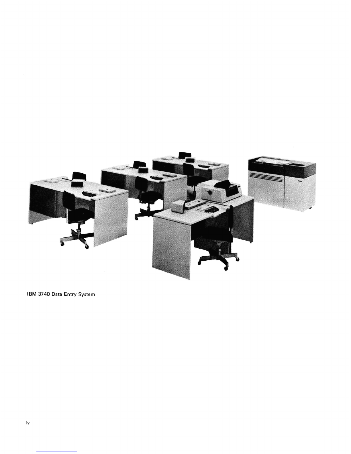
Chapter 1. IBM 3740 Data
Entry
System
SYSTEM
The
that
3740
ized, and
are
The
are keyed
OVERVI
IBM
3740
Data
satisfies a variety
system
entered
is
remote
much
equally
key
like
characters are
and
written
EW
Entry
of
adaptable
entry
they
entered
on
System
key
is
a family
entry
requirements.
to
centralized, decentral-
environments. Original records
are
on a standard
in
temporary
the
disk
after
has been keyed.
A key
element
medium,
means
of
card.
One
of
one
box
be used over
the
disk can be easily
ting
the
of
the
the I BM
storing
data
disk holds
of
80-column cards.
and
over,
rekeying
of
3740
diskette.
and replaces
1898
and
corrected
entire
system
is
This disk
the
records, roughly
Furthermore,
data
that
has been
and
updated,
records
and
cards.
The
3740
system devices are:
•
IBM
3742
Dual Data
Station:
Designed for
use in a centralized transcription location.
•
IBM
data
or
remote
tion
3741 Data
entry
area.
Station
Models 1
use as a stand-alone
location as well as
and
station
in
a centralized transcrip-
of
products
The
keypunch.
storage as
the
they
complete
record
a magnetic recording
is
an economical
standard
the
punched
the
equivalent
the
disk can
entered
thus
elimina-
scrapping
data
2: Designed
on
of
entry
for
in a decentralized
Thus, as shown in Figure 1,
integrated data
ments for data
In
a centralized
lation includes a
for recording
entry
entry
transcription
number
data
on
verter would be included
inch, 9-track
tape
for processing
the
IBM
3740
is
actually
system answering
today's
in various operating environments.
environment, a typical instal-
of
IBM
3742
Dual Data
diskettes. An
to
convert
by
IBM
the
the
3747
data
host
to
central pro-
cessing unit.
In
a decentralized transcription environment, several
3741 Data
site.
bution
part
manufacturing
entered by a
other
In
a remote
one
locations, or, if
Data Stations. Perhaps parts are
house
The
disk as transactions occurred. Periodically
be
transmitted
Station
Stations
For
instance,
department
movement
control
departments
environment,
or
more
IBM
to
several divisions
inventory
Model 2
would
one
station
and
used by
information.
departments
person. A
or
to
a location having a converter.
3741 Data
the
work
data
would
to
the
warehouse via an
with
binary
be located
throughout
might be
the
inventory
Other
stations
where requests for
diskette
a typical
load
situation
Stations
is
heavy,
at
distributed
of a company
be
entered
via
IBM
synchronous
in
the
might
would
would
various offsite
IBM
3742
from
located miles
the
data
the
3741 Data
communications.
require-
Stations
Data
one-half
a business
parts
clerk
be in
parts
be
sent
Dual
a ware-
station
data
an
Con-
IBM
distri-
to
enter
are
to
include
apart.
on
would
•
IBM
3747
Data Converter: Designed
entered
netic
vert
the
•
IBM
provide hard
on
magnetic disk by
tape
for use
data
from
3740
system.
3713
Printer: Designed
by
magnetic
copy
output.
the
other
9-track systems
tape
data
to
disk for updating
to
attach
to
convert
stations
and
to
the
data
to
mag-
to
3741
conby
to
IBM
3740
Data
Entry
System
Page 8

Central ized
Location
IBM 3742 Dual
Data Station
IBM
System/360
IBM System/370
CPU
or other
9-
Track Systems
\
\
\
\
IBM 3747
Data Converter
Receiving
Device
\
IBM 3742 Dual
Data
Station
IBM 3742 Duai
Station
Data
IBM
3742 Dual
Data
Station
IBM 3742 Dual ' I
Data Station I
-------
-
____
Decentral ized
-
--p
I',t
I
,~
/
,'I
,'I
"I
1'1
I
'I
I
'I
, I
I I
I I
, I
, I
I
I
I
I
I
..
1
Remote Location
(offsite)
IBM 3741 Data
Station Model 2
Remote Location
(offsite)
IBM 3741
Station Model 1
Figure
1.
2
An
Integrated
Data
Data
Entry
System
IBM 3741 Data
Station Model 2
Legend:
Hand Transported - - - -
Page 9
IBM
3741
Overview
The
IBM
alone
device
board
unit,
control
binary
synchronous
Data Station
3741 Data
with
one display
unit.
In
and
IBM
Station
one
operator
unit,
addition,
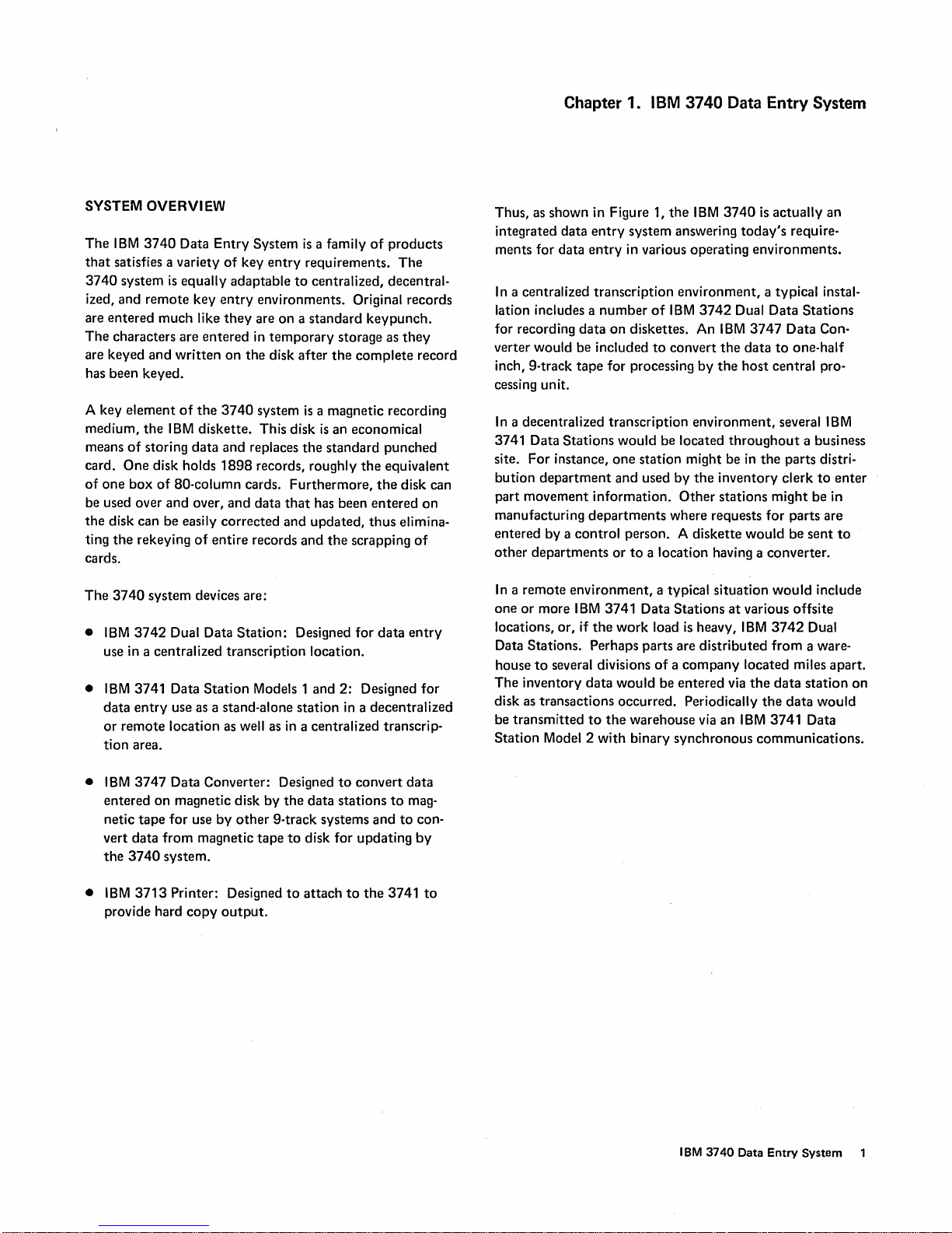
the
communications
3742
Dual Data Station
Model 1 (Figure 2)
station,
one
Model 2
or
which
two
disk
is
equipped
adapter.
is
has
units,
a standone key-
and a
with
a
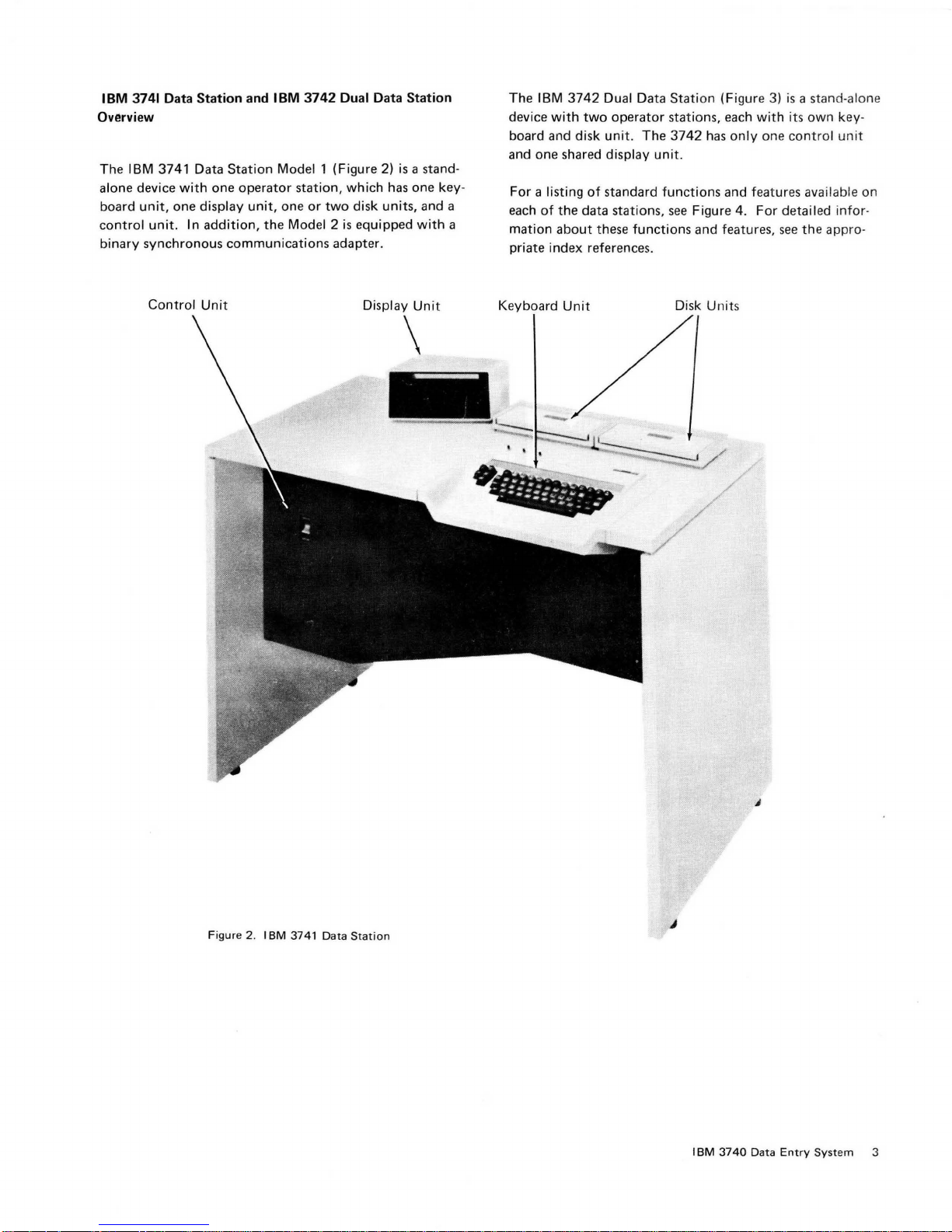
The
IBM
3742
Dual Data
device
with
two
operator
board and
and one shared display
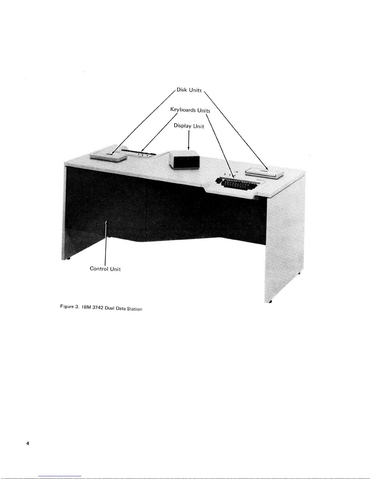
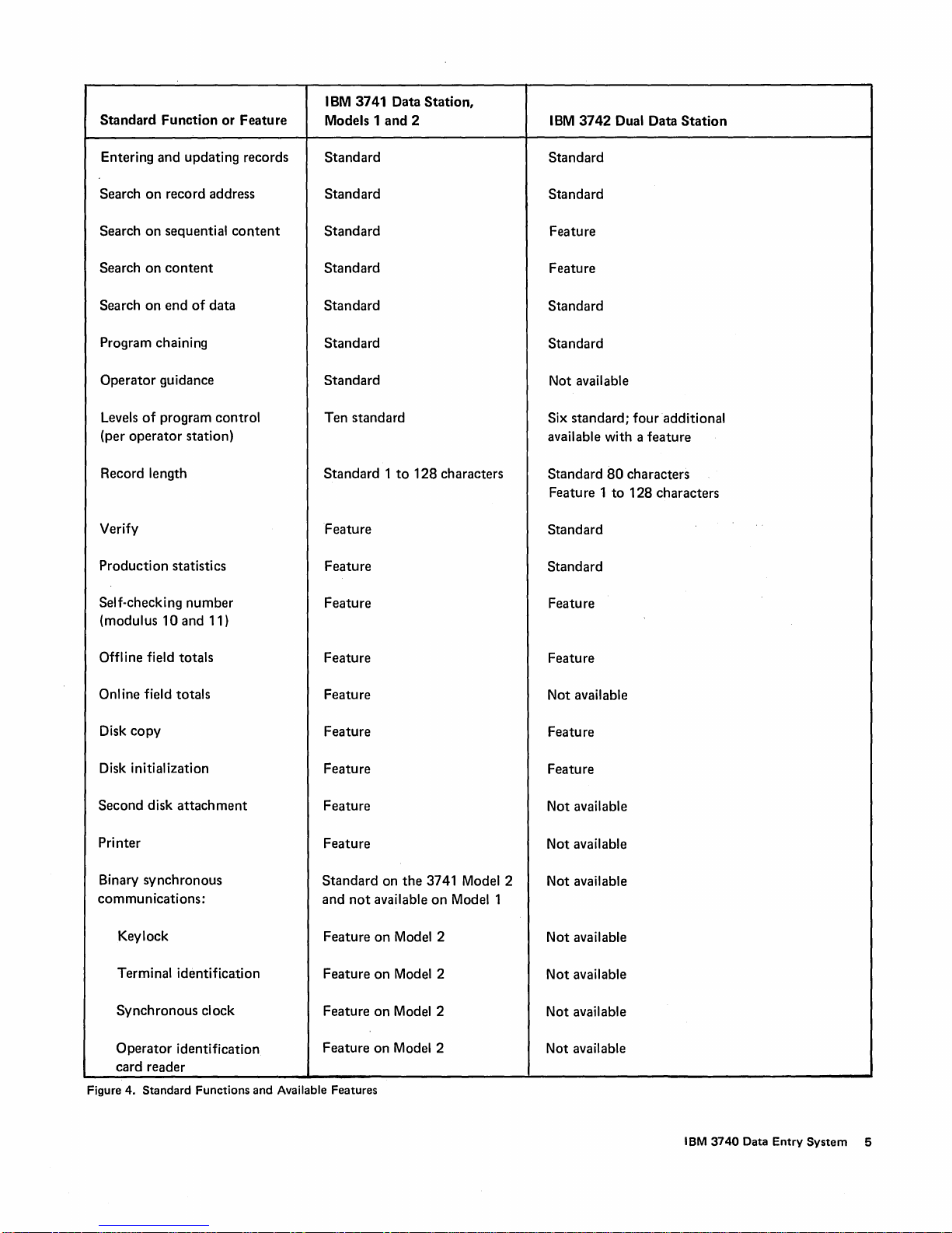
For
each
mation
priate index reference
a listing
of
the
about
disk
unit. The
of
standard
data stations,
these
functions
Station
stations, each
3742
unit
.
functions
see
s.
(Figure 3)
with its
has
only
one
and features available
Figure 4.
and features,
For
detailed
see
is
a stand-alone
own
key
control
the
unit
infor-
appro-
-
on
Control
Unit
Display
Unit
\
Keyboard
Unit
Disk
Unit
s
Figure 2.
IBM
3741 Data
Station
IBM
3740
J
Data
Entry
System 3
Page 10
Page 11
Standard
Function
or
Feature
IBM
3741 Data
Models 1
and
Station,
2
IBM
3742
Dual Data
Station
Entering
Search
Search
Search
Search
and
updating records
on
record address
on
sequential
on
content
on
end
of
Program chaining
Operator
Levels
(per
guidance
of
program
operator
station)
Record length
Verify
Production
Self-checking
(modulus
statistics
number
10
and 11)
content
data
control
Standard
Standard
Standard
Standard
Standard
Standard
Standard
Ten standard
Standard 1 to
Feature
Feature
Feature
128
characters
Standard
Standard
Feature
Feature
Standard
Standard
Not available
Six
standard;
four
available with a
Standard
Feature 1
80
characters
to
128
Standard
Standard
Feature
additional
feature
characters
Offline field
Onl ine field totals
Disk
copy
Disk initialization
Second
Printer
Binary
communications:
Keylock
Terminal identification
Synchronous
Operator
totals
disk
attachment
synchronous
clock
identification
Feature
Feature
Feature
Feature
Feature
Feature
Standard
and
not
Feature
Feature
Feature
Feature
card reader
Figure 4. Standard Functions and Available Features
on
the
3741 Model 2
available
on
on
on
on
Model 2
Model 2
Model 2
on Model 2
Modell
Feature
Not available
Feature
Feature
Not available
Not available
Not available
Not available
Not
available
Not available
Not available
IBM
3740
Data Entry
System
5
Page 12
Chapter 2.
The
IBM
tained within a protective cartridge
Data
is
way
data
IBM
Diskette
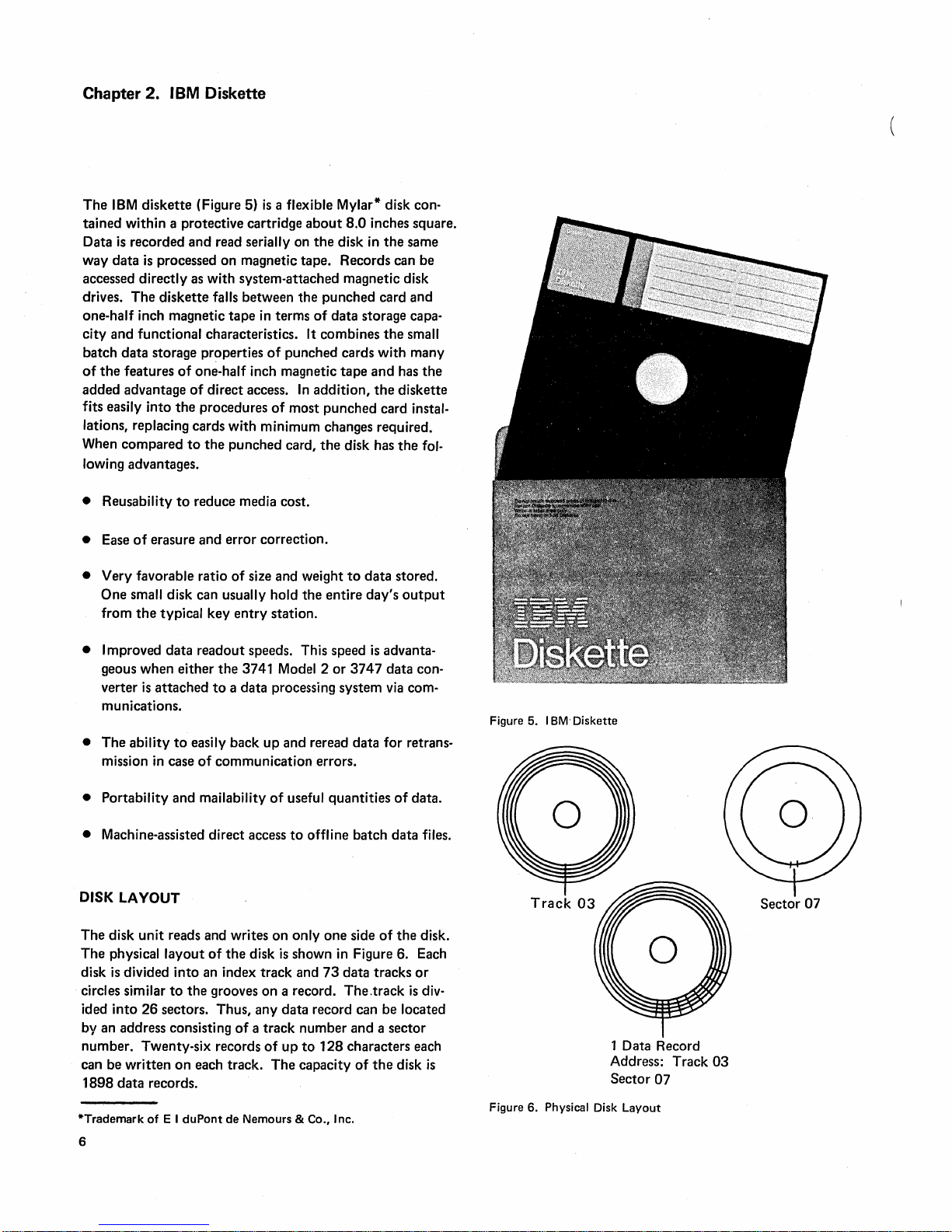
diskette (Figure 5)
recorded and read serially on
is
processed on magnetic tape. Records can be
is
a flexible Mylar* disk con-
about
8.0 inches square.
the
disk
in
the
same
accessed directly as with system-attached magnetic disk
The
drives.
one-half inch magnetic
city and functional characteristics.
batch
of
the
added advantage
fits easily into
diskette falls between the punched card and
tape
in
terms
of
data storage capa-
It combines
data
storage properties
features
of
one-half inch magnetic
of
the
direct access.
procedures
of
punched cards with many
tape
In
addition,
of
most punched card instal-
the
and
the
small
has
diskette
lations, replacing cards with minimum changes required.
When compared
to
the
punched card,
the
disk has
the
lowing advantages.
the
fol-
• Reusability
• Ease
• Very favorable ratio
One small disk can usually hold
from
to
reduce media cost.
of
erasure and error correction.
of
size and weight
the
typical key
entry
station.
the
to
entire
• Improved data readout speeds. This speed
the
geous when either
verter
is
attached
3741 Model 2 or
to
a data processing system
munications.
•
The
ability
to
easily back
in
case
of
mission
communication errors.
• Portability and mailability
• Machine-assisted direct access
DISK LAYOUT
The disk
The physical
disk
circles similar
ided
unit
reads and writes
layout
of
is
divided into an index track and
to
the
grooves on a record. The.track
into
26
sectors. Thus, any
by an address consisting
number. Twenty-six records
can be
written
1898
data
*Trademark
6
on
records.
of
E I
duPont
each track.
up
and reread data for retrans-
of
useful quantities
to
offline batch data files.
on
only
one
the
disk
is
shown
in
73
data tracks
data
record can be located
of
a track number and a sector
of
up
to
128
characters each
The
capacity
de Nemours & Co., Inc.
data stored.
day's
output
is
advanta-
3747
data convia
com-
of
data.
side
of
the
disk.
Figure 6. Each
or
is
div-
of
the
disk
is
Figure 5. 18M- Diskette
Figure 6. Physical Disk
1 Data Record
Address: Track
Sector
07
Layout
03
Sector
07
Page 13
Each
of
the
26
sectors has a sector identification field and a
data field. A field
designated for a specific use.
tains
the
track
tion fields are prerecorded for
initialization process and are
ing normal disk use.
sical record.
record length,
cal record length
128 characters. On
is
length
record
always
of 1 to
Sector Contents After Writing
is
a predefined number
The
number
The
is
128
and sector number.
the
not
The
data
field has space for
maximum record length, called physical
always
128
characters. However,
on
the
3741 can be anywhere from 1
the
standard
80
characters; a variable length logical
characters
is
of
data
positions
identification field con-
The
identifica-
entire disk during an
rewritten
3742,
available
or
changed dur-
the
logical record
as
a feature.
one
the
phy-
logi-
to
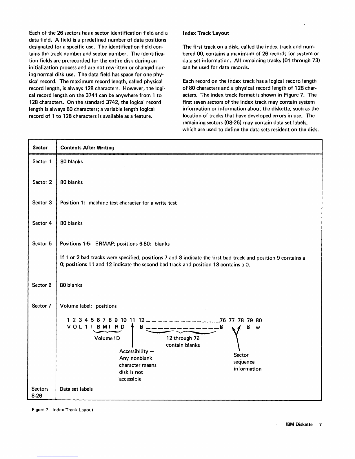
Index Track
The
first track
bered 00, contains a maximum
data set information.
can be used for
Each record
of
80
acters.
first seven sectors
information or information
location
remaining sectors (08-26) may contain data
which are used
Layout
on
a disk, called
All
data
records.
~n
the
index
characters and a physical record length
The
index
track
format
of
the
of
tracks
that
have developed errors in use.
to
define
the
index
track
of
26
records for system
remaining tracks (01
track
has a logical record length
is
shown
in
index track may
about
the
data
sets resident
contain
the
diskette, such as
and num-
through
of
128
Figure 7.
system
set
labels,
on
the
or
73)
char-
The
the
The
disk.
Sector 1
Sector 2
Sector 3 Position 1: machine
Sector 4
Sector 5 Positions 1-5: ERMAP; positions 6-80: blanks
Sector 6
Sector 7 Volume label: positions
80
blanks
80
blanks
test
character for a write
80
blanks
If 1 or 2 bad tracks were specified, positions 7 and 8 indicate the first bad track and position 9 contains a
0; positions
80
blanks
123456789101112
11
and 12 indicate
the
second bad track and position
______________
test
13
contains a
7677787980
O.
VOL11~D
Volume
Sectors
8-26
Figure 7. Index Track Layout
Data set labels
I D 12 through
Accessibil ity Any nonblank
character means
disk
accessible
1
tJ~_tJ
contain blanks
is
not
76
'\
tJ
Sector
sequence
information
w
IBM
Diskette 7
Page 14

Index
Track
Data
Set
Labels
Sectors 8
as
mation
extent
and
the
Position
through
data
set labels. A
about a data
(BOE), end
the
record length
data
set label, see Figure
by
Position Representation
26
of
the
data
set label defines
set
on
of
data
for
the
index
track
are used primarily
pertinent
the
disk such as beginning
(EOD),
data
end
set.
of
For
extent
8.
of
Data
exact
on
Field Name Position Purpose
Header 1 1-4
Label identifier for system appl ication;
5 Reserved
Data set name
6-13
User name
14-22 Reserved
Record length 23-27
Logical record length *
infor-
of
(EOE),
layout
of
the
Index Track in
for
data
set
Any
One
Sector
of Sectors 8-26.
must
be H D R 1. *
Beginning
extent
End
of
of
(BOE)
extent
(EOE)
Bypass
data
Accessibility
Write
protect
set
28
Reserved
29-33 Identifies
contain
contain
34
35-39
40
41
Reserved
Identifies
Reserved
The
IBM
If a B
is
processed. This coding allows
same disk.
42
43
This field
If this field
be a blank,
the
address
the
track
the
sector
the
address
3747
data
present,
must
contains a P,
in
which case
number,
number.*
converter
the
data
contain
of
the
first sector of
position
of
the
last sector reserved for
requires
set
is
ignored. If a blank
the
user
a blank in
the
both
order
disk can be read only. Otherwise this field
reading
the
31
must
that
to
store
for processing
and
writing are
data
set. Positions
be 0, positions
th
is
this field
contain
is
present,
programs and
to
permitted.
data
32
take
and
set. *
a B
the
data
place.
29
33
or
a blank.
data
on
and
set
the
30
is
must
* Indicates an
Figure 8 (Part 1 of 2). Data
8
entry
required' by
Set
Label Layout
the
3740
system.
Page 15
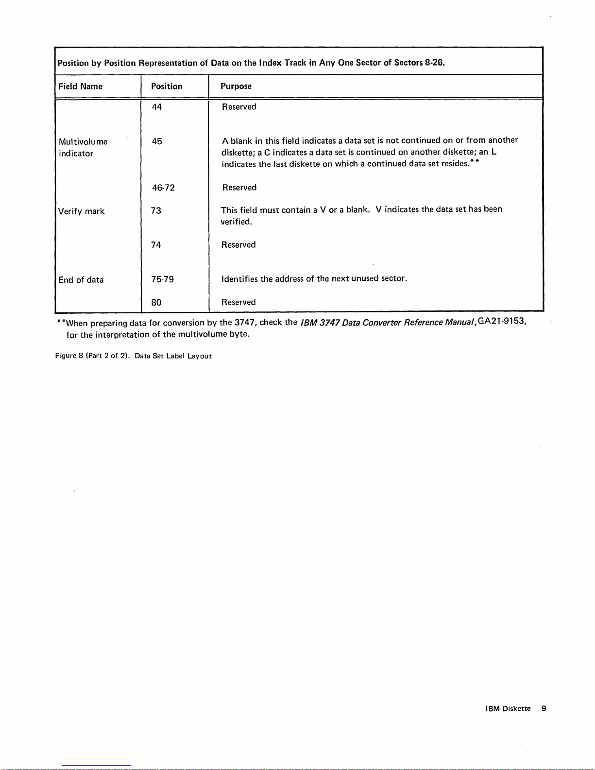
Position
by
Position
Representation
of
Data
on
the I ndex
Track in
Any
One
Sector
of
Sectors
8-26.
Field Name
Multivolume
indicator
Verify
mark
End
of
data
**When preparing
for
the
interpretation
Figure 8 (Part 2
of
data
2). Data
Position
44
45
46-72
73
74
75-79
80
for
conversion
of
the
Set
Label
Purpose
diskette;
This field
verified.
by
the
multivolume
Layout
Reserved
A blank in
indicates
Reserved
Reserved
Identifies
Reserved
3747,
byte.
this
field indicates a
a C indicates a
the
last
diskette
must
contain
the
address
check
the
of
IBM
data
set
is
not
data
a V
the
on
or
next
set
which a
a blank.
is
continued
continued
V indicates
unused sector.
continued
on
another
data
set
the
on
or
diskette;
resides. * *
data
set
from
has
another
an
L
been
3747 Data Converter Reference Manual,GA21-9153,
IBM
Diskette 9
Page 16
Chapter 3. Data Station Operating Information
The
entering, updating, verifying
is
performed
operation.
control
upon
store
and
communication
Each
mode
buffers, keys, and
each
mode.
The
mode
the
status
operation
display codes are:
by
the
data
stations
The
sequence
unit
within
the
mode
in which
transfer
of
line
for
Mode
Enter
Update
Verify V
Field
Search S
Read index X
Modify M
Field
data
between
of
operation
operation
of
the
the
3741
correct
totals
(offline)
of
the
data
the
within
the
is
the
information
is
display unit. Some
and
or
finding
using
operations
station
unique,
indicated by a
3742
is
station
is
the
station
keyboard,
and,
displayed
and
Display
directly depende.nt
functioning. Buffers
their
of
data
different
performed
to
allow
disk,
and
therefore,
is
different
code
displayed
of
the
modes
corresponding
Code
E
U
C
F
on
modes
by
display.
the
a disk
of
the
use
for
on
<?f
of
MODES
Enter
Enter
can
results if
on
on
lower and
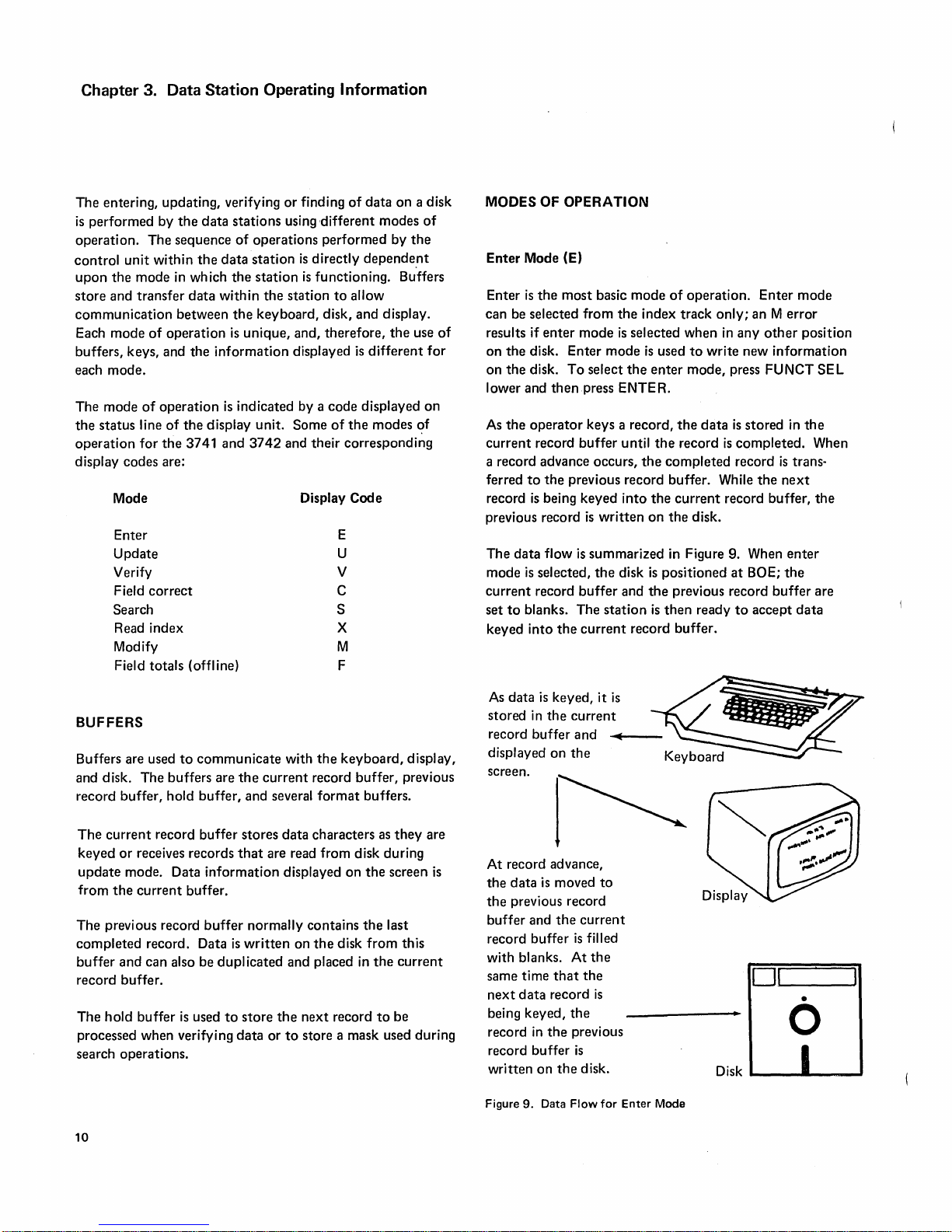
As
current
a record advance occurs,
ferred
record
previous record
The
mode
current
set
keyed
OF
Mode (E)
is
the
be selected
enter
the
disk.
the
disk.
then
the
operator
record
to
the
is
being
data
flow
is
selected,
record
to
blanks.
into
the
OPERATION
most
basic
from
the
mode
is
Enter
mode
To
select
the
press ENTER.
keys a record,
buffer
until
previous record buffer. While
keyed
into
is
written
is
summarized
the
disk
buffer
and
The
station
current
mode
of
operation.
index
track
selected when
is
used
to
write
enter
mode,
the
data
the
record
the
completed
the
current
on
the
disk.
in Figure 9. When
is
positioned
the
previous record
is
then
ready
record
buffer.
Enter
only;
an M
error
in
any
other
new
information
press FUNCT
is
stored
is
completed.
record
is
the
next
record buffer,
enter
at
BOE;
the
buffer
to
accept
mode
position
SEL
in
the
When
trans·
the
are
data
BUFFERS
to
buffers
hold
record
buffer.
also be
is
communicate
are
buffer,
buffer
information
buffer
dupl
used
Buffers are used
and disk.
record buffer,
The
keyed
update
from
The
completed
buffer
record buffer.
The
processed when verifying
search operations.
10
The
current
or
receives records
mode. Data
the
current
previous record
record. Data
and
can
hold
buffer
with
the
the
and several
stores
that
normally
is
written
icated
to
store
data
current
record buffer, previous
format
data
characters as
are read from disk during
displayed
contains
on
the
and
placed in
the
next
or
to
store a mask used
keyboard,
buffers.
on
the
the
disk
from
the
record
to
display,
they
screen
last
this
current
be
are
is
during
As
data
is
keyed,
stored
in
the
record
buffer
displayed
screen.
At
the
the
buffer
record
with blanks.
same time
next
being keyed,
record
record
written
Figure
on
record advance,
data
is
previous record
and
buffer
data
record
in
the
buffer
on
9.
Data
current
and
the
moved
the
current
is
At
that
the
previous
is
the
disk.
Flow
it
to
filled
the
the
is
for
is
~
Keyboard
Disk .....
Enter
Mode
0,--1
_____
__
•
o
-'I
OJ
Page 17
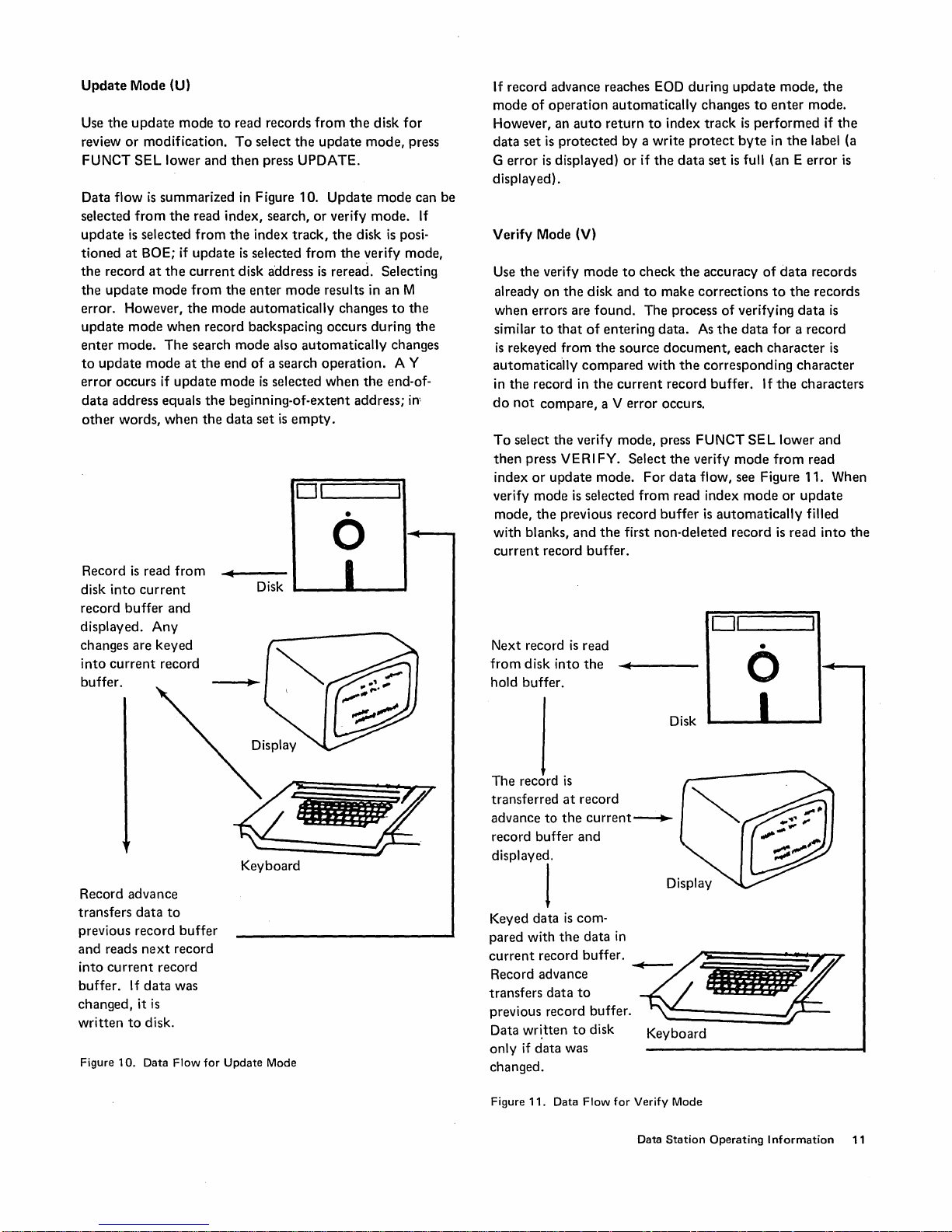
Update
Use
review
FUNCT
Data flow
selected
update
tioned
the
the
error. However,
update
enter
to
error
data
other
Record
disk
record
displayed.
changes are
into
buffer.
Mode (U)
the
update
or
modification.
SEL
lower and
is
summarized in Figure 10.
from
is
selected
at
BOE; if
record
at
the
update
update
mode
mode
mode.
The
mode
occurs
if
address equals
words,
when
is
read
into
current
buffer
Any
keyed
current
record
the
when
and
mode
to
read records
To
select
then
press UPDATE.
read index, search,
from
the
index
update
current
from
the
search
at
update
is
selected
disk address
the
enter
mode
automatically
record backspacing occurs during
mode
the
end
of
mode
is
the
beginning-of-extent address;
the
data
set
the
track,
from
mode
also
automatically
a search
selected
is
empty.
011.-
from
update
Update
or
verify
the
is
reread. Selecting
results in an M
changes
operation.
when
------'I
o
from
...........
~
---
Disk
the
disk
mode,
mode
mode.
disk
is
the
verify mode,
the
•
for
press
can be
If
posi-
to
the
the
changes
A Y
end-of-
in-
If record advance reaches EOD during
mode
of
operation
However, an
data
set
is
protected
error
is
G
displayed) .
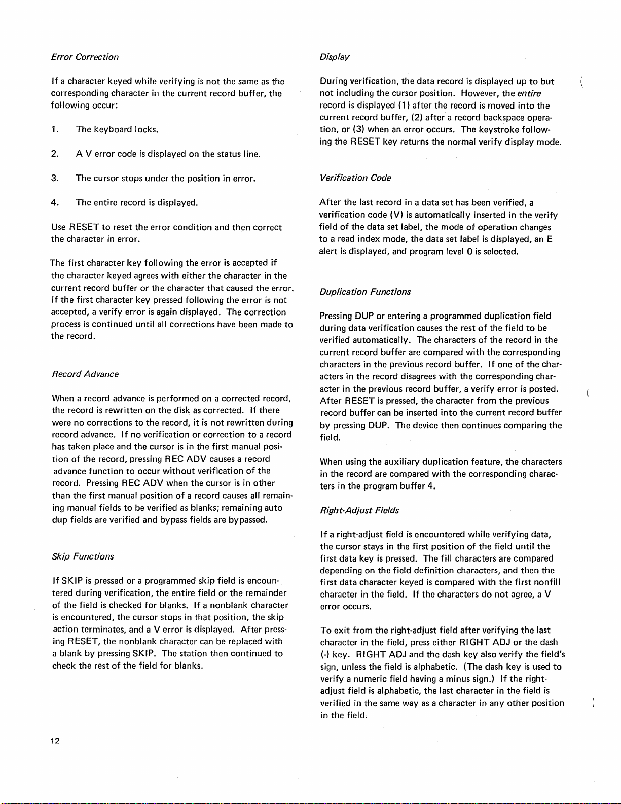
Verify Mode (V)
Use
already
when
similar
is
automatica'ily
in
do
To
then
index
verify
mode,
with
current
displayed)
the
verify
on
the
errors are
to
that
rekeyed
the
not
select
from
record in
compare,
the
press VERI FY. Select
or
update
mode
the
previous record
blanks,
record
automatically
auto
return
to
by a write
or
if
the
mode
to
check
disk and
found.
of
the
compared
the
verify mode, press FUNCT
mode.
is
selected
and
buffer.
to
The
entering
source
with
current
a V
error
For
from
the
first non-deleted record
changes
index
track
protect
data
set
the
accuracy
make
corrections
process
data.
As
document,
the
corresponding
record
buffer.
occurs.
the
verify
data
flow, see Figure 11. When
read index
buffer
is
DL-I
Next record
from
hold buffer.
disk
is
into
read
the
......
'-----
update
is
of
the
automatically
to
enter
is
performed
byte
in
full (an E
of
to
verifying
data
for
each
character
If
SEL
mode
from
mode
__
mode,
the
data
the
the
lower
or
is
read
----oJ
•
o
the
mode.
if
the
label (a
error
is
records
records
data
is
a record
is
character
characters
and
read
update
filled
into
the
Record advance
transfers
previous record
and
into
buffer.
changed,
written
Figure
data
reads
current
If
it
to
10.
next
record
data
is
disk.
Data
to
buffer
record
was
Flow
for Update Mode
nm~
~~
Keyboard
Disk
The
record
is
transferred
advance
record buffer
to
at
the
record
and
current~
diSPlayel
Keyed data
pared with
~:;:~~
transfers
previous record buffer.
Data
only
changed.
Figure
is
com-
the
data
in
:~~~~c:uffer.
data
to
written
if
data
11.
to
disk Keyboard
was
Data Flow
~~
for
Verify Mode
Data
Station
__
lIM
i
f~~'"
_ ___ 1
__
_
Operating
Information
11
Page 18
Error Correction
If a
character
corresponding
following
1.
The
2. A V
keyed
character
occur:
keyboard
error
while verifying
in
locks.
code
is
displayed
the
is
current
on
not
record
the
the
status
same as
buffer,
line.
the
the
Display
During verification,
not
including
record
current
tion,
or
ing
the
the
is
displayed (1)
record buffer, (2)
(3) when an
RESET key returns
the
data
cursor
position. However,
after
the
after
error
occurs.
the
record
is
displayed
record
is
a record backspace opera-
The
keystroke
normal verify display mode.
the
moved
up
to
entire
into
follow-
but
the
3.
The
cursor
stops
under
the
4.
The
entire
record
is
displayed.
Use
RESET
the
character
The
first
the
character
current
If
the
accepted,
process
the
record.
character
record
first
character
a verify
is
continued
to
reset
in
keyed
buffer
the
error
condition
error.
key
following
agrees with
or
the
character
key pressed following
error
is
again displayed.
until all
corrections
Record Advance
When a record advance
the
record
is
rewritten
were
no
corrections
record advance.
has
taken
place
and
tion
of
the
record, pressing R
advance
record. Pressing REC ADV when
than
ing manual fields
dup
function
the
first manual position
fields are verified
is
performed
on
the
disk as
to
the
record, it
If
no
verification
the
cursor
EC
to
occur
without
of
to
be verified as blanks; remaining
and
bypass fields are bypassed.
Skip Functions
If
SKIP
is
teredduring
of
the
field
is
encountered,
action
terminates,
ing RESET,
a blank
check
by
the
pressed
rest
or a programmed
verification,
is
checked
the
pressing SKIP.
of
for
the
cursor
and
a V
nonblank
the
field
the
entire
blanks. If a
stops in
error
character
The
for
blanks.
position in error.
and
then
correct
the
error
is
accepted
either
the
character
that
caused
the
the
error
The
correction
have been made
on a corrected
corrected.
is
not
rewritten
or
correction
is
in
the
first manual posi-
ADV causes a record
verification
the
cursor
a record causes all remain-
skip field
field
or
the
nonblank
that
position,
is
displayed.
can be replaced with
station
then
continued
If
to
of
is
in
other
is
encoun-
remainder
character
the
After
record,
there
a record
the
if
in
the
error.
is
not
during
auto
skip
press-
to
to
Verification Code
After
the
last record
verification
field
to
a read index
alert
code
of
the
data
is
displayed, and program level 0
(V)
set
label,
mode,
in a data
Duplication Functions
Pressing DUP
during
verified
current
characters
acters in
acter
in
After
RESET
record
by
pressing DUP.
field.
When using
in
the
ters
in
or
entering a
data
verification causes
automatically.
record
buffer
in
the
previous record buffer. If
the
record disagrees with
the
previous record buffer, a verify
is
pressed,
buffer
can be inserted
The
the
auxiliary
record are
the
compared
program
buffer
Right-Adjust Fields
If a right-adjust field
the
cursor
first
data
depending
first
data
character
error
occu rs.
To
exit
from
character
(-)
key.
RIGHT
sign, unless
verify a
adjust
verified in
in
the
numeric
field
field.
stays in
key
on
character
in
in
the
the
is
pressed. The fill characters are
the
field
keyed
the
field. If
the
right-adjust field
the
field, press
ADJ
the
field
is
field having a minus sign.) If
is
alphabetic,
same way as a
set
has been verified, a
is
automatically
the
mode
the
data
programmed
The
characters
are
compared
the
character
into
device
then
duplication
with
4.
is
encountered
first
position
definition
is
compared
the
characters
either
and
the
dash key also verify
alphabetic. (The dash
the
last
character
inserted in
of
operation
set
label
is
is
selected.
the
rest
of
of
with
the
corresponding
from
the
current
continues
feature,
the
corresponding
while verifying
of
the
characters, and
with
do
after
verifying
RIGHT
character
in
the
verify
changes
displayed, an E
duplication
the
the
the
corresponding
one
error
the
field until
the
not
ADJ
in
any
field
field
to
record in
of
the
is
posted.
previous
record
comparing
the
characters
charac-
data,
compared
then
first nonfill
agree, a V
the
or
the
the
key
is
used
the
right-
the
field
other
position
be
the
char-
char-
buffer
the
the
the
last
dash
field's
to
is
12
Page 19
If a verification
right-adjust field, an X error
changed by
Press RIGHT ADJ
error
two
depressions
occurs while verifying
is
displayed.
of
RIGHT ADJ
or
the
dash key, if applicable,
every programmed right-adjust field. Press
when
one
right-adjust field immediately follows
when
right-adjust fields
to
press RIGHT ADJ
adjust
field causes an error
contain
or
the
all fill characters. Failure
dash key
on
the
next
at
the
data
the
sign
The
sign can be
or
the
the
key even
another
end
of
keystroke.
of
a
dash key.
to
exit
a right-
from
and
Field
Correct
Field
correct
with a minimum
mode
can be selected
the
field
moves
Mode (C)
mode
correct
to
the
first position of
number
mode, press
field can be rekeyed
of
the
field
is
reached,
first position
of
the
may be used
of
keystrokes.
from
the
FI
the
as
if in
the
the
cursor
field and
the
to
correct
verify
mode
ELD COR.
current
enter
mode. When
then
moves back
mode
changes
an entire field
The
field
correct
only.
To
The
cursor
field, and
to
verify.
the
the
to
select
end
the
When a right-adjust field
record
on
the
3742
or
3742
with
the
128
but
RI
GHT
ADJ has
tion
ture,
indicator
or
81
for
is
129
3742,
In verify mode, RIGHT ADJ
only
when
the
cursor
adjust field
field
of
the
sor
is
(to
verify a zero
is
full (the cursor will have moved
next
field). If these keys are pressed
in
any
other
is
the
last field in an 80-character
or
a 128-character record
feature
not
for
and
is
and
yet
been pressed,
the
3741
the
cursor
or
in
the
first position
or
the
field has been verified
or
3742
is
not
the
dash key should be used
a blank field)
position, an R error occurs.
Signs
If
the
units position
a negative
number
field are verified separately.
units position verifies
ed,
only
the
digit
is
not
affected.
The dash key also verifies
If
the
units position
(dash)
but
the
pared. If
from
ter
with
corrected,
the
field using RIGHT ADJ.
in a numeric right-adjust field, press ALPHA
the
dash key.
To
field
of
a numeric right-adjust field
(0
zone),
the
sign and
The
first
keystroke
the
digit. I f
portion
exit
is
from
the
of
a right-adjust field has a 0 zone
is
alpha,
the
entire
the
changed.
the
field, use
sign.
the
entire
character
To
character
The
character
verify a dash charac-
Hexadecimal Data
Verify hexadecimal
data
in
the
same way
1. Press HEX.
2. Press
two
character
decimal digits
the
last keystroke for
keys
wanted.
correxponding
The
character
that
character.
the
with
displayed.
of
to
the
when
the
sign
the
is
changed.
it
is
is
on
the
3741
cursor
posi-
the
128 fea-
the
right-
or
when
the
first position
the
cur-
contains
value
of
the
for
the
is
correct-
(0
zone)
dash key.
is
com-
Exit
SH
1FT
entered:
to
the
hexa-
verified
after
Selecting field
while processing a programmed
results
valid
in
changes back
backspace moves
correct
in
an M error. FIELD ADV
the
field
to
mode
correct
the
verify mode
the
cursor
mode.
out
when
auto
The
of
not
in
field in verify
and
CHAR ADV are
field
when
a field
the
current
verify mode
mode
correct
mode
or
character
field.
or
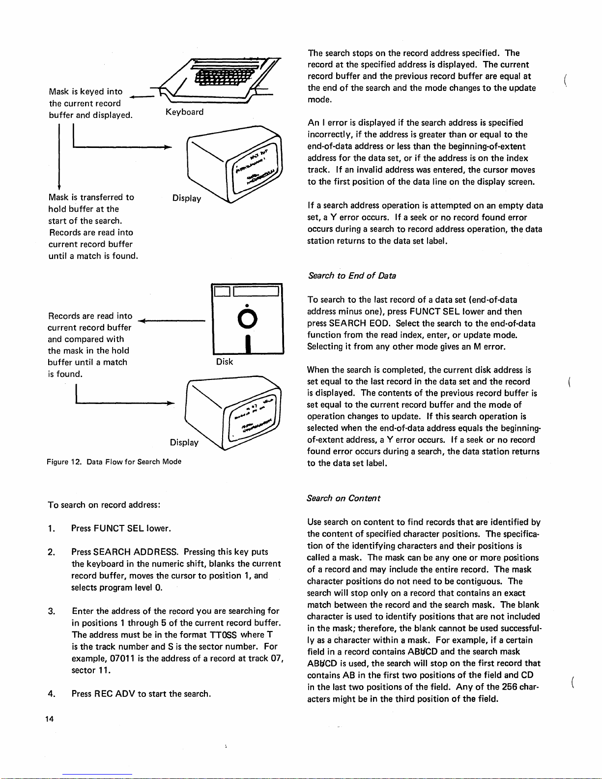
Search Mode (S)
Use
search
mode
to:
• Search
• Search
• Search
• Search
is
For
Note: After pressing any search key,
R
EC
sing FUNCT SEL lower and RETURN
pressing FUNCT
enter
enter
data
ADV,
on
record address from read index,
mode.
to
end
of
data
from
read index or
on
content
on
sequential
from
content
read index
from
mode.
flow
information, see Figure 12.
the
search
SEL
operation
lower
can be canceled by pres-
and
UPDATE.
update,
update
or
update.
read index,
but
before pressing
TO
INDEX
or
mode.
update,
or
by
or
Search on Record Address
To
search for a record in a
location.
The
track
beginning-of-extent address,
one,
or
the
address
ses. Select
operation
Selecting
other
the
search mode
from
the
the
search by record address
mode causes an M selection error.
data
and
sector
the
of
any record
to
read index,
set, key its
track
and
sector
address specified can be
end-of-data address minus
between
do
a search
update,
these
by
or
enter
function
two
addres-
record address
mode.
from
any
the
Data
Station
Operating
Information
13
Page 20
. .
Mask
IS
keyed Into _
the
current
buffer and
record
. d Keyboard
dlsplaye .
I
Mask
is
transferred
hold buffer
start
Records are read into
current
until a match
Records are read into
current
compared
and
the
mask
buffer until a match
is
found.
Figure 12. Data
at
of
the
search.
record buffer
is
record buffer
in
the
Flow
the
found.
with
hold
for
The search stops
at
record
record buffer and
4j'iflllI~
to
DL-I
__
.....I
•
"""'
......
____
_
o
Disk
Search Mode
the
end
of
mode.
An
I
error
incorrectly, if
end-of-data address
address
track.
to
If a search address
set, a Y error occurs.
occurs during a search
station
Search
To
address minus one), press FUNCT
press SEARCH EOD. Select
function
Selecting it
When
set equal
is
set
operation changes
selected when
of-extent
found
to
for
If
an invalid address was
the
first position
returns
to
search
from
the
to
displayed. The
equal
to
error
the
data
on
the
record address specified. The
the
specified address
the
previous record
the
search and
is
displayed
the
the
data
to
the
End
of
Data
to
the
last record
the
from
any
search
is
the
last record
contents
the
current
the
address, a Y
occurs during a search,
set
label.
the
if
the
address
read index, enter,
to
end-of-data address equals
is
or
less
than
set,
or
if
of
the
data line on
operation
If
a seek
to
record address
data
set
of a data
other
mode gives an M error.
completed,
in
of
record
update.
error
occurs. If a seek
greater
is
displayed.
mode changes
search address
than
the
beginning-of-extent
the
address
entered,
is
attempted
or
no record
label.
SEL lower
the
search
or
the
current
the
data
the
previous record buffer
buffer
If
this search
the
The
buffer
to
is
or
equal
is
on
the
cursor
the
display screen.
on
found
operation,
set
(end-of-data
to
the
update
disk address
set
and
and
the
operation
data
station
current
are equal
the
update
specified
to
the
the
index
moves
an
empty
error
the
and
then
end-of-data
mode.
the
record
mode
of
the
beginning-
or
no
record
returns
at
data
data
is
is
is
To
search
on
record address:
11.
EC
SEL lower.
ADDRESS. Pressing this key puts
the
numeric shift, blanks
the
cursor
to
level
O.
address
07011
number
ADV
of
the
record
of
the
in
the
format
and S
is
the
is
the
address of a record
to
start
the
search.
you
current
sector
1. Press FUNCT
2. Press SEARCH
the
keyboard in
record buffer, moves
selects program
3. Enter
4. Press R
14
the
in positions 1 through 5
The
address must be
is
the
track
example,
sector
the
current
position 1, and
are searching
record buffer.
TTOSS where T
number. For
at
track
for
07,
Search on
Use search on
the
tion
called a mask. The mask can be
of
a record
character positions
search
match between
character
in
the
ly as a character within a mask.
field in a record contains ABIiCD
ABlICD
contains
in
the
acters might be in
Content
content
content
of
of
specified character positions.
the
identifying characters and
and
may include
will
stop
the
is
used
mask; therefore,
is
used,
AB
in
the
last
two
positions
to
find records
the
do
not
need
only on a record
record and
to
identify positions
the
the
search will
first
the
third
two
of
the
blank
positions
the
position
stop
field.
that
are identified by
The
specifica-
their
positions
anyone
entire record.
to
that
cannot
For
or
more
positions
The
be contiguous. The
contains
search mask. The blank
that
example, if a certain
and
the
on
the
of
Any
of
the
an
exact
are
not
included
be used successful-
search mask
first record
the
field and
of
the
256
field.
is
mask
that
CD
char-
Page 21

Searching by
beginning with
the
current
Select
or
update
mode
content
the
next
sector and
the
search on
content
mode. Selecting this
causes an M
error
is
accomplished
record.
all
The
previous sectors are
function
function
to
occur.
To
in
a forward direction,
records
from
from
search
function:
Press FUNCT SEL lower and SEARCH CONTENT.
1.
The
record
into
the
current
display screen for review
2.
Key
the
search mask
Do
this
by modifying
ferred
into
the
current
the
mask
that
record buffer as
currently
the
record
in
the
record buffer
into
the
current
record
buffer
was
just
transferred
the
mask can be used
hold
buffer
and
displayed
or
modification.
the
current
mask
that
was
buffer
or
and entering new data. Also,
into
ing it.
Note: On
mask includes
be certain
is
correct.
FUNCT
acters
during
3.
Press R
when
data
is
displayed.
the
CONTENT, and REC ADV
reenter
Following a search
fer and
data.
record
the
3742
with
the
128
feature
all
128
that
the
To
blank
SEL
lower and DELETE REC. Blank char-
in
a mask indicate
the
search
EC
ADV
to
the
data
station
characters.
portion
the
current
the
operation.
start
the
finds
The
of
the
record
record buffer, press
position
search.
the
The
record containing
being searched for (search mask), and
To
continue
same mask, press FUNCT
the
search mask.
the
previous record
If
the
entire
found,
the
search stops
searching
operation,
data
set
for
SEL
lower, SEARCH
in
that
order. Do
the
current
buffer
contain
has been searched and no
and
an S
played.
If a
deleted
the
data
search
momentarily
deleted
deleted record
record
is
in
the
deleted record does
continues
and a deleted record warning 6 appears
on
the
record matches
is
displayed.
read during a search
not
status
line. However, if
the
mask,
the
search
on
match
contained
not
checked.
the
read index
any
other
on
content
is
transferred
on
record
buffer.
just
trans-
by blanking
the
current
without
the
search
operator
not
displayed
is
not
compared
search stops
the
records using
not
record buf-
the
same
error
is
content
the
mask,
the
data
stops
and
in
the
chang-
must
the
record
dis-
and
the
in
the
the
For example,
the
part
search on
the
following procedure:
Press FUNCT SEL lower
1.
The
into
Press FUNCT SEL lower
2.
the
Key
3.
the
4. Press REC ADV
When
the
AB
126
is
displayed.
repeat steps 1
that
data set
search stops and an S
to
search a
number
in
AB
126
content
record
the
current
the
current
data
using
currently
current
record buffer.
part
number
record buffer.
station
positions 15-19,
To
find
and
4. If
that
contains
data
in positions 15-19,
AB
126
in
record buffer.
AB
to
start
finds
the
the
next
the
AB
error
is
Search on Sequential Content
Search
on
sequential
but
is
faster. Use search
the
records
fields are
in a data
in
ascending
ceeding record
record). Having
faster searching because
on
Search
sequential
or backward direction;
from within a
than
the
location
tion
will locate
If
a search fails
played. Failure
record
is
in
the
the
requirement
search failure, a search
same search mask.
track
in
order
content
on
set
are arranged so
order
must
have a higher value
the
search fields in ascending
of
the
content
therefore,
data
set
at a track
of
the
specified record,
the
specified record.
to
find
the
record sought, an S
to
find a record can
data
set
if one
of
ascending order. Therefore,
content
To
do
this, first
to
search
through
set
for
all records containing
perform
as
the
search mask. Use
and
SEARCH CONTENT.
the
hold buffer
and
126
the
the
first record
search
DELETE REC
in
positions 15-19
search.
stops
is
transferred
containing
and
the
record containing AB126,
search
cannot
126
in positions 15-19,
find a record
displayed.
is
similar
sequential
(the search field
to
search
content
that
the
than
on
only
search
of
each suc-
the
preceding
order
skipping
operates
of
records.
in
either
a forward
if
the
search
is
and
sector address higher
the
search opera-
started
error
occur
even
though
or
more records
do
not
after
may be initiated using
return
to
the
index
the
entire
data
set.
a
to
blank
of
record
in
~he
content,
when
permits
is
dis-
the
meet
a
the
Data
Station
Operating
Information
15
Page 22
Select search on sequential
enter
or
update
mode.
To
content
select this search:
from
the
read index,
10.
The
other
fourth
than
position
1.
of
the
header
1 field
is a number
Press FUNCT
1.
TENT. The record
transferred into
played.
2.
Press FUNCT SEL lower and DELETE REC
the
screen.
3.
Key
the
4.
Press R
When
the
record
Read Index Mode (X)
The
read index mode displays records
representing
system
delete records
The
have been
data. A special procedure
3741
or
met
SEL
search mask
EC
ADV
is
found,
the
volume label,
in
this mode.
3742
checks
in
the
data
lower and SEARCH
currently
the
current
to
start
it
to
set label:
into
in
record buffer and dis-
the
current
the
search.
is
displayed.
the
data
is
For
data
see if
the
SEQ
CON-
the
hold
buffer
to
record buffer.
on
the
index
track
set labels, and
required
to
write
flow, see Figure 13.
following
conditions
is
blank
other
or
11. The record has been deleted.
When a header 1 record
the
3741 or
previous I ist. I f any
displayed.
When
from
one
of
Modify Mode
Use
the
the
index track. Key
modify
mode can be selected from
is
selected
mode
REC, RESET, and REC ADV are
modify mode.
to
read index
of
modify
3742
update,
the
can be selected from
verify,
index
track,
the
11
conditions
(M)
modify mode
by pressing FUNCT SEL lower and
from
another
All
after
mode.
checks
of
these
enter,
all
to
the
others
the
first
in
sectors
the
first eight
conditions
or
search
11
conditions
is
present, a B
write
data
record
the
read index
mode, an M
the
modify
give an F error.
keystroke
08
through
conditions
exist, a B
mode
are
error
or
to
delete
to
be
written,
error
mode. DELETE
the
only
following
26
is
read,
in
error
is
attempted
checked.
is
displayed.
records
then
M.
The
mode
only; if it
occurs. No
valid keys
The
mode
the
the
is
If
any
on
select
modify
other
in
the
reverts
selection
1. The beginning-of-extent address
sector
01.
2.
The
end-of-extent address
sector
26.
3.
The
end-of-extent address
of-extent
4.
The end-of-data address
extent
5.
The end-of-data address
tor
6.
The
7.
The
for
not
8.
The
of
address.
address plus 1.
01.
sector
record length
the
3741 or
equal
third
extent,
is
00
or
the
to
80
for
character
end
of
extent
greater
is
equal
3742
the
of
the
is
is
3742.
or
is
greater
is
less
greater
greater
than
to 0 or
with
record address
end
O.
is
than
26.
the
of
less
than
than
the
than
the
than
track
greater
128
feature
data
track 01,
track
beginning-
end-of-
75, sec-
than
of
beginning
is
other
74,
128
or
than
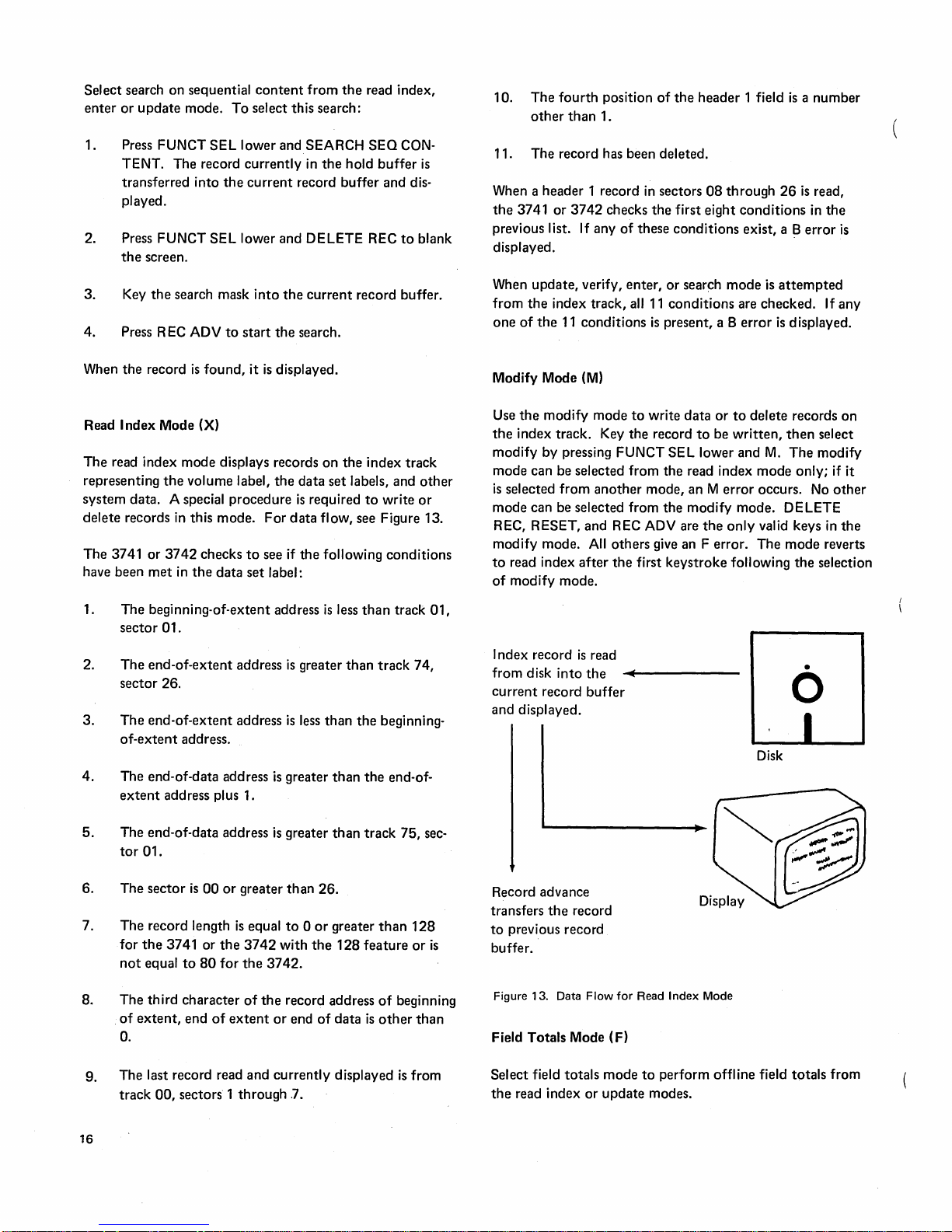
I ndex record
from disk
current
and displayed.
Record advance
transfers
to
previous record
is
buffer.
Figure 13. Data
Field Totals Mode (F)
into
record
the
is
read
the
buffer
record
Flow
..........
for
------
Read
Index
•
o
Disk
Mode
9. The last record read
track
00,
sectors 1 through
16
and
currently
.7.
displayed
is
from
Select field
the
read index
totals
or
mode
update
to
perform offline field
modes.
totals
from
Page 23
STARTING
INFORMATION
Using
this
key
when
at
end
of
extent:
When
the
3741
or
3742
record, previous
blanks,
status
the
address
blank.
Closing
changes
the
blank,
and
A
position 9 and
have been successful,
RECORD
Use REC ADV
record
buffer
the
current
Pressing REC ADV
record
Pressing
search
read index
read,
but
volume
the
write
current
and
line displays
00000.
the
the
the
3741
test
on
are
disk address
displayed in
REC ADV
operations.
record,
the
program
the
mode
All
cover
on
disk
status
it
is
not
displayed,
label
is
checked.
disk
cannot
or
3742
is
made;
10
of
ADVANCE
during
the
index
transferred
record
buffer
power
is
turned
and hold
buffers are filled
machine-not-ready disk
(X), program level 0,
other
positions
the
diskette
to
wait
be
processed,
waits
if
not
the
status
sector
OPERATION
read index
track.
to
the
contains a deleted
is
incremented
during
the
current
during
buffers
on
that
(W).
The
and
the
accessibility field in
If
the
accessibility field
an A error
for
the
disk
successful, ??
line.
If
08
is
read.
mode
The
contents
previous record
by
modify
search
index
sector_
mode
on,
the
are filled
with
and
the
status
has
been inserted
volume
to
be removed.
is
displayed in
all
previous
to
read
of
the
buffer
record.
one.
mode
starts
current
N's.
status
current
line are
label
is
displayed,
the
current
writes
one
of
with
The
(N),
is
is
tests
next
unless
The
the
the
disk
not
Gives an E
1.
Selects
2.
3.
4.
Pressing this
1.
2.
3.
4. Increases
If
data
read, R
step
3. The
reaches
Pressing
to
check
automatically
tion
error
record
record in
fer
and
the
and
program
Selects read
Displays
key
Transfers
to
the
previous
Reads
the
and
moves
the
record.
Replaces
previous
has
not
EC
ADV
mode
the
EOD address.
REC
for
blanks
occurs, verification
is
moved
the
displayed.
next
record
error.
level
O.
index
mode.
the
data
set
label.
in
update
mode
the
contents
record
next
record
the
cursor
to
the
old
record
record
buffer.
the
current
been
performs
changes
ADV
during
verify all trailing
into
hold
buffer
The
disk address
entered
all
to
verify
in
all remaining manual fields
the
previous record
is
then
current
is
read
into
(if
data
was
entered):
of
the
current
buffer.
into
the
the
first manual
on
the
since
the
of
the
enter
when
mode
auto
is
completed.
moved
disk address increases
the
record
current
disk
with
by
1.
current
preceding
record
causes
fields. If
buffer.
to
the
hold
buffer.
record
The
buffer
position
contents
record
steps
except
advancing
the
station
and
no
verifica-
present
The
current
buffer
of
of
was
buf-
by
1,
Pressing REC ADV
1. Transfers
to
the
fields
and
2.
Writes
3.
Adds
one
disk address.
4.
Sets
the
Moves
5.
during
the
record
previous record
executing
the
record
on
to
the
end-of-data address
current
the
cursor
record
to
the
enter
mode:
from
the
current
buffer
skipping all manual
all
automatic
disk.
buffer
to
first manual field
fields.
and
blank.
record
the
position.
buffer
current
If a verification
that
caused
corrections
ADV causes
corrections
ADV
is
pressed
tion
of
a record,
when a modification
alternate
An
be selected
dash will
record advance
skip
and
cursor
at
return
the
lower
and
also establish
error
the
error.
to
the
the
record
are
made,
when
the
method
by
pressing
appear
in
function
duplicate
the
time
machine
K.
Inserting a disk
the
record have been made, pressing REC
fields
of
normal
occurs,
current
to
of
position
record advance are
to
the
cursor
When verification
to
be
written
the
record
is
the
cursor
is
record
the
present
record advance in
FUNCT
the
Data
39
in
enter
that
normal
mode.
Station
SEL
in
the
mode
follow
mode,
or
turning
stops
is
on
the
not
rewritten.
in
the
first
is
not
verified,
record has
enter
lower
status
is
changed
the
position
not
press
the
Operating
at
the
complete
disk. If
If R
manual
been
mode
and
then
line.
The
so
of
executed.
FUNCT
power
Information
column
and
no
EC
posi-
except
made.
can
R.
that
the
To
SEL
on
will
A
17
Page 24
DELETED RECORDS
Every
nondeleted
immediately preceding
mark
is
not
is
mark
the
a D
and
SEL
and
modify
Mode Considerations
changed
record as being
written
preserve
lower
NUM
SH I FT.
index
record
displayed.
to a control
in
the
first
the
data
and
then
mode
deleted.
simultaneously press DELETE REC
To
must
on
a disk has a
the
data
characters; this address
For
a deleted record, this address
address mark which identifies
Deleted records normally have
data
position.
in
the
first position, press FUNCT
delete
records
be used.
for
Deleted Records
To
on
data
delete
the
address mark
a record
index track,
When a record advance occurs and a
hold
buffer
(next
sequential record
nondeleted
passing all deleted records
is
encountered
record
vious record
When
record
function
record
is
read
during record backspacing,
is
read
into
the
buffer
unchanged.
deleting a record,
buffer
remains unchanged
is
performed.
into
encountered.
current
the
contents
the
record
and
deleted
is
current
record
deleted),
record
If a
deleted
the
deleted
buffer
with
of
the
previous
a record advance
the
buffer
the
is
in
next
record
pre-
the
by-
Enter Mode: Pressing DELETE REC during
blanks
the
current
at
the
first manual position.
unchanged.
Update Mode: If,
index
track, a
the
buffer,
deleted
buffer
the
If a
ing,
When
D in
content
beep
sor
deleted
Verify Mode: When selecting verify
track,
into
If verify
the
nondeleted
either
previous record
record. If a
when
record
is
deleted
the
previous record
deleting a record,
the
current
in
the
occurs when
is
positioned
record.
the
first
the
current
mode
currently
case,
record
buffer
and positions
The
previous record
during
update
deleted
a record advance occurs during
not
record
current
displayed record
record
the
record
deleted
transferred
is
encountered
buffer
the
record
buffer,
record
the
delete
at
the
first manual position displaying
nondeleted
record buffer.
is
selected
previous record
is
from
read
is
read
buffer
record
to
the
is
first
character
and
buffer
function
record in
update
is
into
the
buffer
mode selection
into
will
contain
is
in
the
previous record buffer.
during record backspac-
not
changed.
the
remainder
remains unchanged. A
is
complete.
mode
the
data
or
a deleted one,
current
is
the
verify
blanked.
enter
mode
the
cursor
buffer
from
the
current
current
update
is
changed
from
set
record buffer.
the
the
is
mode
the
record
same
record
mode,
to
of
the
The cur-
index
read
and
next
is
a
the
Search Mode: Pressing
blanks
at
the
first manual position.
and
the
the
search
the
current
record.
CE
MODE
CE
mode
troubleshooting
cribe
how
points
mode.
Pressing FUNCT
machine in
positions
Pressing RESET several times
index
mode
the
machine leaves CE
3741
may
The
EOD and verify mark
current
should
In
the
current
record
at
operation
and
previous record buffers
is
used
the
this
mode
out
how
it
the
CE mode.
38,
39
and
with
be changed
when
the
be checked.
DE
record
buffer
current
by
is
SEL lower
the
CE
disk address are unchanged. If
terminates
the
customer
equipment.
works
entered
40.
label
mode,
and
mode
LETE REC during search
and
The
previous record
on a deleted
engi neer when testi
This manual
or
how
and
how
followed
The
status
returns
from
sector
the
program buffers
therefore
of
the
data
was
entered
positions
it
is
to
by
line displays CER in
the
08
should
set
the
record,
contain
does
used
but
get
out
the"
key
machine
displayed.
be checked.
label
that
may be in
the
merely
of
mode
cursor
buffer
both
deleted
ng
not
the
puts
to
the
After
of
the
was
error
or
des-
the
and
18
(
Page 25
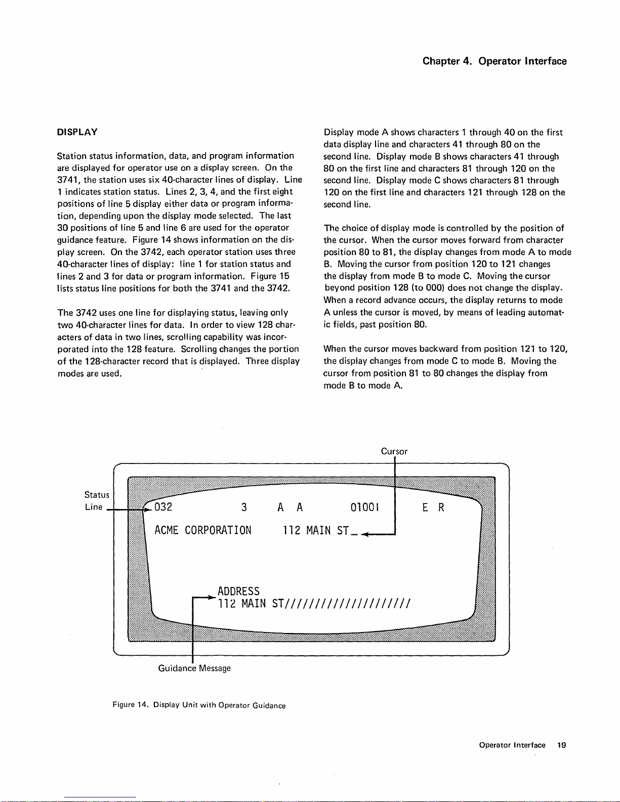
Chapter 4. Operator Interface
DISPLAY
Station
are displayed
3741,
1 indicates
positions
tion,
30
guidance feature_ Figure
play screen. On
40-character
lines 2
lists
The
two
acters
porated
of
modes
status
information,
for
operator
the
station
of
depending
positions
and
status
3742
40-character lines
of
data
into
the
128-character record
are used_
uses six
station
line 5 display
upon
of
line 5 and line 6 are used
the
lines
3 for
data
line positions
uses
one
in
two
the
128
status. Lines 2, 3,
the
3742,
of
display: line 1
or
line
for
lines, scrolling capability was incor-
feature. Scrolling changes
data,
and
program
use
on
a display screen. On
40-character
4,
either
data
or
display
14
program
for
for
data.
mode
shows
information
each
operator
for
information.
both
the
3741 and
displaying status, leaving only
In
order
that
is
displayed.
information
lines
of
display. Line
and
the
first
program informa-
selected.
for
the
on
station
station
status
Figure
the
to
view
the
Three
the
eight
The
last
operator
the
dis-
uses
three
and
15
3742.
128
char-
portion
display
Display mode A shows
data
display line
second
80
second line. Display
second line.
The
the
position
B.
the
When a record advance occurs,
A unless the
ic
When
the
cursor
mode B to
line. Display
on
the
first line
120
on
the
first line
choice
of
display
cursor. When
80
to
81,
Moving
the
cursor
display from
beyond
position
cursor
fields, past position
the
cursor moves backward
display changes
from position
mode
characters 1 through
and
characters 41
mode
B shows
and
characters
mode
C shows
and
characters 121
mode
is
the
cursor
the
display changes
from
position
mode B to
128
is
from
A.
(to
000)
moved,
80.
mode C to
81
to
mode
80
through
characters
81
through
characters
through
controlled
moves forward
does
the
by
means
changes
from
120
C.
Moving
not
display
from
mode
the
by
to
change
of
position 121
40
on
the
80
on
the
41
through
120
on
81
through
128
the
position
from
character
mode A to
121 changes
the
cursor
the
display.
returns
leading
B.
display
to
automat-
Moving
from
first
the
on
mode
mode
to
120,
the
the
of
Status
Line
Figure
ACME
Guidance Message
14.
Display
3
CORPORATION
ADDRESS
112
MAIN
Unit
with
Operator
Guidance
A A
112
MAIN
01001
ST
_~---I
ST/////////////////////
Cursor
E R
Operator
Interface
19
Page 26
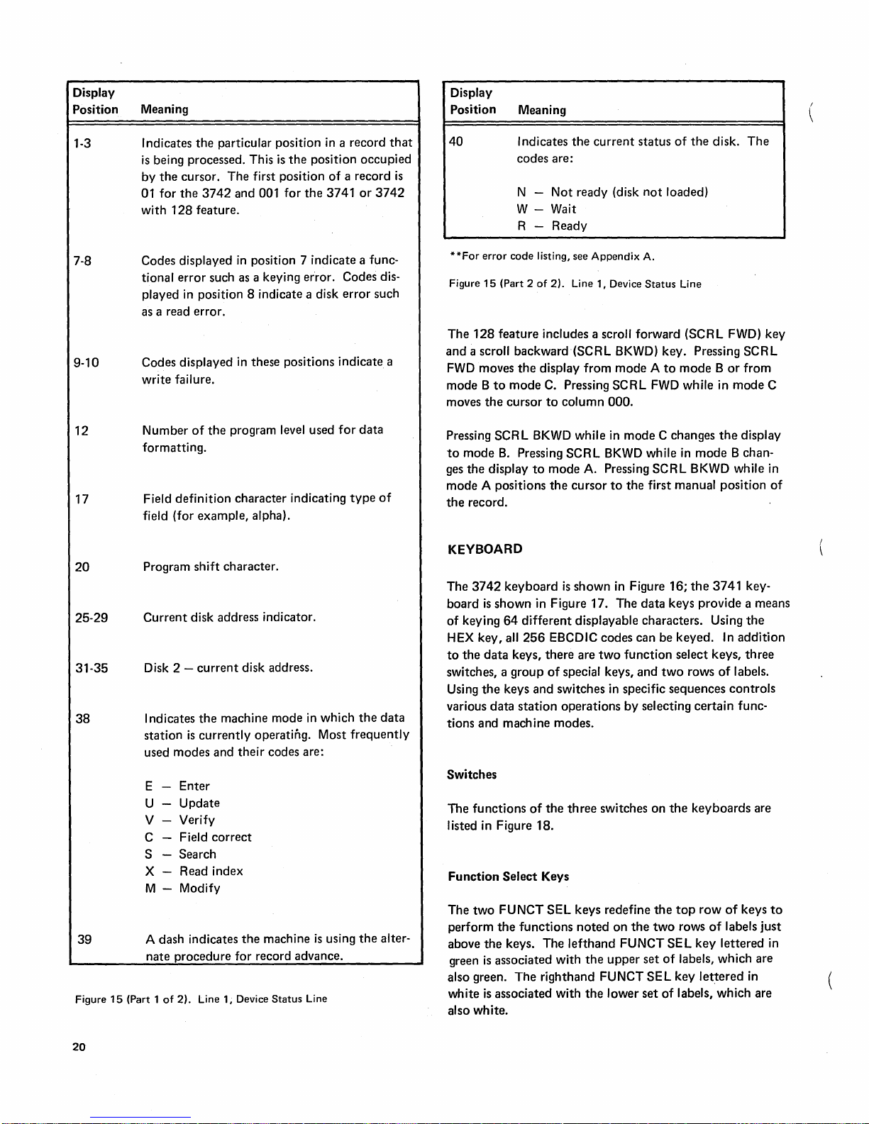
Display
Position
Meaning
Display
Position Meaning
1-3
7-8
9-10
12
17
20
25-29
31-35
38
39
Figure
Indicates
is
by
01
with
Codes
tional
played
the
being processed. This
the
cursor.
for
the
3742
128
feature.
displayed
error
such as a keying error. Codes dis-
in position 8 indicate a disk
as a read error.
Codes
displayed in these positions indicate a
write
failure.
Number
of
the
formatting.
Field
definition
field (for example, alpha).
Program
Current
Disk 2 -
I ndicates
station
used
E
U
V
C
S
shift
disk address indicator.
current
the
is
currently
modes
and
Enter
Update
Verify
Field
correct
Search
X Read index
M - Modify
A dash indicates
nate
procedure
15
(Part 1
of
2).
Line 1, Device
particular position in a record
is
the
position
The
first position
and 001
in
for
the
position 7 indicate a func-
program level used
character
indicating
of
a record
3741
error
for
occupied
or
3742
such
data
type
character.
disk address.
machine
mode
operating. Most
their
codes are:
the
machine
in
which
is
frequently
using
the
the
for record advance.
Status
Line
that
is
of
data
alter-
40
Indicates
the
current
status
of
codes are:
Not
N -
ready (disk
not
loaded)
W - Wait
R - Ready
**For
error
code
listing, see
Figure
15
(Part 2
of
The
128
feature
and
a scroll backward (SCRL BKWD) key. Pressing
FWD moves
mode B to
moves
the
includes a scroll forward (SCRL FWD) key
the
display
mode
C.
cursor
to
Pressing SCR L BKWD while in
to
mode
B.
Pressing
ges
the
mode
the
display
A positions
record.
to
2).
Line 1, Device
from
Pressing
column
SCRL
mode
A. Pressing
the
cursor
Appendix
mode A to
SCRL
000.
mode
BKWD
to
the
A.
Status
Line
mode B or
FWD while in
C changes
while
in
SCRL
first manual position
KEYBOARD
The
3742
keyboard
board
is
shown
of
keying
64
HEX key, all
to
the
data
switches, a
Using
the
keys
various
data
keys,
group
station
is
shown
in Figure 16;
in Figure 17. The
different
256
displayable characters. Using
EBCDIC codes can be
there
are
two
of
special keys,
and
switches in specific sequences
operations
data
function
and
by
selecting
keys provide a means
keyed.
select keys,
two
tions and machine modes.
Switches
The
functions
of
the
three
switches
on
the
listed in Figure 18.
Function
The
perform
above
green
also green.
white
Select
two
FUNCT
the
functions
the
keys.
is
associated with
The
is
associated with
Keys
SEL
keys redefine
noted
on
the
The
lefthand
the
FUNCT
upper
righthand FUNCT
the
lower
the
top
two
rows
SEL
set
of
labels, which are
SEL
key
set
of
labels, which are
also white.
the
disk.
The
SCRL
from
mode
the
display
mode
B chan-
BKWD while in
the
3741
key-
the
In
addition
three
rows
of
labels.
controls
certain
keyboards
row
of
of
labels
key
lettered
lettered
func-
are
keys
just
in
C
of
to
in
20
Page 27
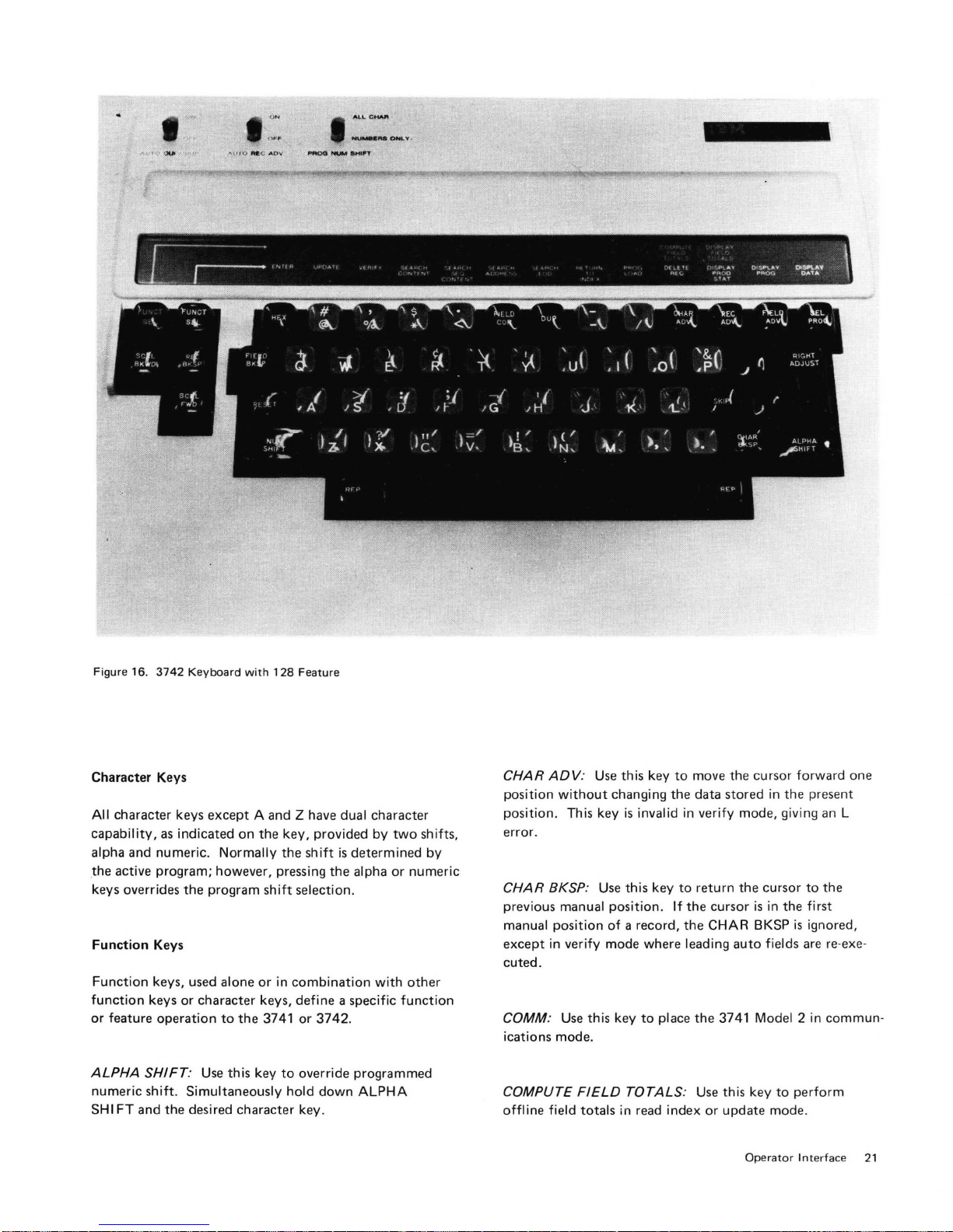
~
......
....
,
.,.....
,
.... ,
.........
.....
..,."
Ofr«.y
.
Figure 16.
Character Keys
All
capability,
alpha and
the
keys overrides
Function
Function
function
or
feature
ALPHA
numeric
SH I FT
3742
Keyboard
character keys
as
indicated
numeric. Normally
active program; however, pressing the alpha
the
Keys
keys, used alone
keys
or
operation
SHIFT
:
shift.
Simultaneously
and
the
desi red character key.
with
128
except
A and Z have dual character
on
the
key
the
program
character keys,
Use
to
this
the
shift
or
3741
key
in
to
Feature
, provided
shift
selection .
combination
define
or
3742.
override programmed
hold
down
by
is
determined
with
a specific
ALPHA
two
shifts,
or
numeric
other
function
by
CHAR
ADV
:
position
position
error.
without
. This key
CHAR BKSP:
previous
manual
except in
cuted.
COMM:
ications mode .
COMPUTE
offline
manual
position
verify
Use
FIELD
field
totals
Use
this
key
to
move the cursor
changing the data stored in the present
is
invalid in
Use
this
position. If
of
a record,
mode where leading
this
key
to
TOTALS:
in
read index
verify
mode, giving
key
to
return
the
the
cursor
the
CHAR
auto
place the 3741 Model 2 in
Use
this
key
or
update mode .
cursor
is
in the
BKSP
fields
to
forward
is
perform
an
to
the
first
ignored,
are
re-exe-
commun-
one
L
Operator
Int
erface
21
Page 28
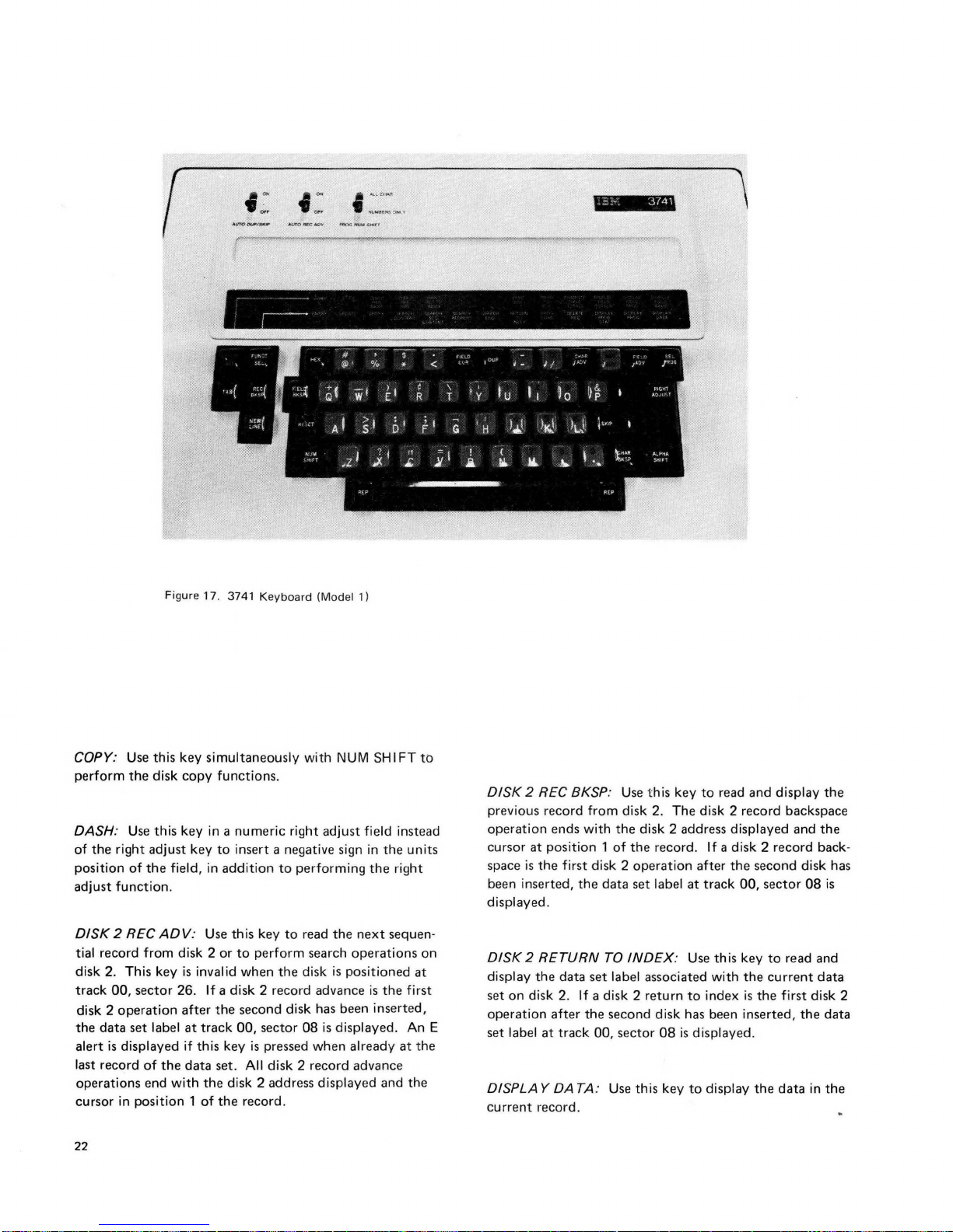
Figure 17. 3741
Keyboard
(Mod
el 1)
COPY: Use this key
simultaneously
with
NUM
SH I FT
to
perform
the
disk
copy
functions.
DASH: Use this key
in a numeric
right
adjust
field instead
of
the
right
adjust
key
to
insert a negative sign in
the
units
position
of
the
field,
in
addition
to
performing
the
right
adjust
function
.
DISK
2 REC
ADV:
Use this key
to
read
the
next
sequen-
tial record from disk 2
or
to
perform
search
operations
on
disk 2. This key
is
invalid
when
the
disk
is
positioned
at
track
~O,
sector 26.
If
a disk 2 record advance
is
the
first
disk 2
operation
after
the
second
disk has been inserted,
the
data
set label
at
track
~O,
sector
08
is
displayed. An E
alert
is
displayed if this key
is
pressed
when
already
at
the
last record
of
the
data
set. All disk 2 record advance
operations
end
with
the
disk 2 address displayed and
the
cursor in position 1
of
the
record.
22
DISK
2 REC BKSP: Use t his key
to
read
and
display
the
previous record
from
disk 2. The disk 2 record backspace
operation
ends with
the
disk 2 address displayed and
the
cursor
at
position 1
of
the
record. If a disk 2
record
back-
space
is
the
first disk 2
operation
after
the
second
disk has
been inserted,
the
data
set
label
at
track
~O,
sector
08
is
displayed.
DISK
2 RETURN
TO
INDEX:
Use this key
to
read and
display
the
data
set
label associated with
the
current
data
set
on
disk 2.
If
a disk 2
return
to
index
is
the
first disk 2
operation
after
the
second
disk has been inserted,
the
data
set label
at
track
~O,
sector
08
is dis
played .
DISPLA Y DA TA: Use
this
key
to
display
the
data
in
the
current
record.
Page 29
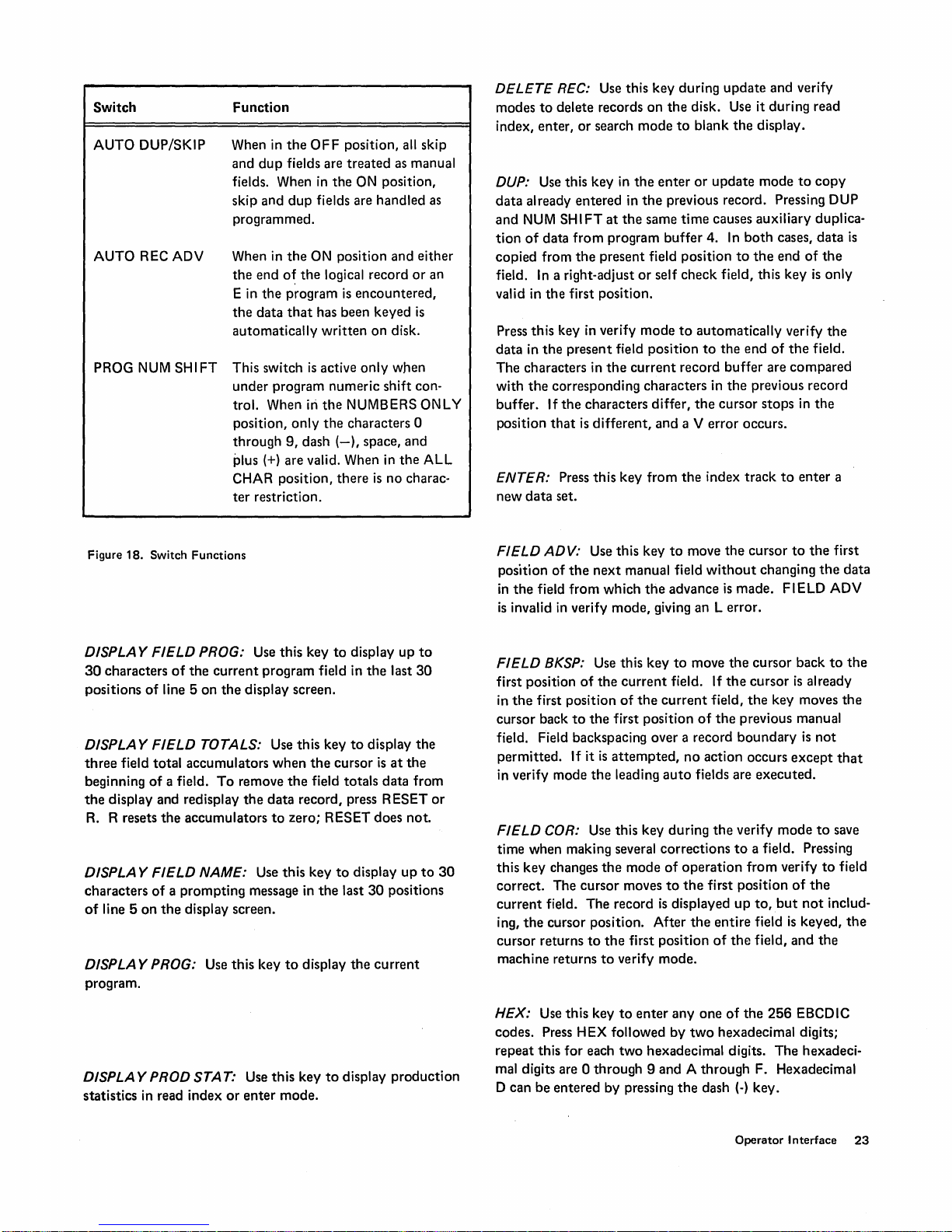
Switch
AUTO DUP/SKIP
AUTO REC ADV
PROG
NUM
SH I FT
Function
When
in
the
OFF
position, all skip
and
dup
fields are
fields. When
skip and
dup
treated
in
the
ON
fields are handled as
programmed.
When in
the
E in
the
automatically
This switch
under
trol. When in
position,
through
the
ON position and either
end
o~
the
logical record
the
data
program
that
is
encountered,
has been keyed
written
is
active
on
only
program numeric shift con-
the
NUMBERS ONLY
only
the
characters 0
9,
dash
(-),
space, and
plus (+) are valid. When in
CHAR position,
ter
restriction.
there
is
as manual
position,
or
is
disk.
when
the
ALL
no charac-
an
DELETE REC: Use this key during
modes
to
delete records
index, enter,
or
search
DUP: Use this key in
data
already
and
NUM
tion
of
copied from
field.
valid in
Press
data
in
The
characters in
with
the
buffer. If
position
ENTER: Press
new
data
entered
SH I FT
data
from
the
In
a right-adjust
the
first position.
this
key
in
the
present
corresponding characters in
the
characters differ,
that
is
different,
this
set.
on
the
disk. Use it during read
mode
to
blank
the
enter
or
in
the
previous record. Pressing DUP
at
the
same
time
program
buffer
4.
present field position
or
self
check
verify
mode
to
automatically
field position
the
current
to
record buffer are
the
and
a V error occurs.
key from
the
index
update
and verify
the
display.
update
mode
to
copy
causes auxiliary duplica-
In
both
cases,
data
is
to
the
end
of
the
field, this key
the
end
of
is
verify
the
field.
only
the
compared
the
previous record
cursor
stops
in
the
track
to
enter
a
Figure 18. Switch
DISPLA Y
30
characters
positions
DISPLA Y
three
field
beginning
the
display and redisplay
R.
R resets
DISPLA Y
characters
of
line 5
on
Functions
FIELD
of
FIELD
of
FIELD
PROG: Use this key
of
the
current
line 5
on
the
TOTALS: Use this key
total
accumulators
a field.
the
To
accumulators
NAME: Use this key
of a prompting
the
display screen.
program field in
display screen.
when
remove
the
data
to
message in
DISPLA Y PROG: Use this key
program.
to
the
the
field totals
display
to
cursor
up
the
last
display
is
at
data
the
from
record, press RESET
zero; RESET does not.
to
to
display
the
display
last
the
30
positions
current
up
to
30
the
to
or
30
FIELD
position
in
is
FIELD
first position
in
cursor
ADV:
Use this key
of
the
the
field
from
invalid
in
verify
BKSP: Use this key
of
the
first position
back
to
the
next
manual field
which
mode,
the
current
of
the
first position
to
move
without
the
advance
is
giving an L error.
to
move
field. If
current
of
field,
the
field. Field backspacing over a record
permitted.
in verify mode
FIELD
time when making several
this key changes
correct.
current
ing,
the
cursor
machine returns
If it
is
attempted,
the
leading
no
auto
COR: Use this key during
corrections
the
mode
of
operation
The
cursor
moves
to
the
field. The record
cursor position. After
returns
to
the
to
is
displayed
first position
verify mode.
the
action occurs
fields are
the
first position
entire
of
the
cursor
to
the
changing
the
made. FIELD ADV
the
cursor
back
the
cursor
is
already
the
key moves
previous manual
boundary
is
not
except
executed.
verify
mode
to
to
a field. Pressing
from
verify
to
of
the
up
to,
but
not
includ-
field
is
keyed,
the
field,
and
the
first
to
the
that
save
field
data
the
the
DISPLA Y PROD STAT: Use
statistics in read index
or
enter
this
mode.
key
to
display
production
HEX:
Use
this
codes. Press H
repeat
this for each
mal digits are 0
D can be
entered
key
to
enter
EX
followed by
two
anyone
hexadecimal digits. The hexadeci-
of
two
hexadecimal digits;
through 9 and A through
by pressing
the
dash
the
256
EBCDIC
F. Hexadecimal
(-)
key.
Operator Interface
23
Page 30

NEW
LINE:
printer.
NUM SHIFT: Use this key
shift
or
the
NUMBE
down
to
NUM
Use this key
override
RS
ON
SHIFT
the
PROG
L Y position. Simultaneously hold
and
the
to
skip
to
a new line
to
override programmed alpha
NUM
SH I FT
desired
character
on
switch when
key.
the
in
RESET: Use this key
keyboard
To
RESET. Use RESET
the
1.
lockout
correct
disk errors, hold
following:
A search
while
the
(the
content
search
to
reactivate
keyboard
down
in
any mode
or
search sequential
is
taking place.
the
keyboard
is
made inoperative) occurs.
NUM
SH I FT
of
operation
when
and
to
content
press
cancel
function
PRINT
being displayed.
returns
pressing
PRINT
or
3741
printed. This key
this
and
entered.
PROG
store
FUNCT
corresponding
REG
record.
REG:
Use this key
to
the
mode
PRINT
TO
EOD: Use this key
to
print
from
is
in
the
read index mode,
key
in
the
enter
displays
ADV:
the
LOAD:
auxiliary duplication
SEL
lower, PROG LOAD, and
to
Use this key
to
After
the
printing
of
operation
REC.
the
current
is
invalid
mode changes
data
set
label
Use this key
data
a program key.
to
print
the
record
currently
is
complete,
being used before
to
print
an entire
disk position
the
entire
in
the
verify mode. Pressing
the
mode
of
the
current
to
store new programs and
for program level 4. Press
then a number
move
to
the
to
data
next
EOD. If
the
set
to
read index
data
sequential
3741
data
set
the
is
set being
to
2. A pending program selection
3. A modify index
4.
A
hex
~eying
5. Functional error.
6.
Function
RETURN
index mode. Pressing RETURN TO INDEX causes
following actions:
1. Returns
2.
3.
4.
TO
INDEX:
to
Displays
Makes
equal
Updates
label if a record has been
the
to
the
the
the
function.
sequence.
select.
Use
current
contents
data
current
contents
end-of-data address field in
data
of
or
this key
the
of
to
set
label.
set
label.
previous record
the
current
entered.
program load
change
to
buffer
record buffer.
the
operation.
read
the
data
set
REG
BKSP: Use this key
first manual position
already in
the
vious record.
the
mode
Pressing R
results
correct
search
24
cursor
current
changes
in
mode
mode
the
first manual position of
moves back
The
previous record buffer
record buffer. Pressing REC BKSP
the
mode
EC
BKSP
no
action. Record backspacing
causes an L error. Record backspacing
is
limited
of
to
from
to
to
move
the
cursor
the
the
to
the
the
current
update
record. If
the
current
first manual field
is
made equal
mode.
beginning-of-extent address
in
the
current
record.
back
the
of
in
field
to
the
cursor
record,
the
pre-
enter
in
to
the
I nserts a blank in
5.
has been
is
mode.
6. Selects program level
The
EOD field in
end-of-data address
address when RETURN TO INDEX
tion
is
needed
If
this
happens, press RETURN TO INDEX. This
the
EOD field
been released in
processing
completion
written
in
in
is
completed,
of
the
the
data
is
equal
case
enter
the
data
the
enter
function.
the
verify
in
enter
mode
O.
set
label
to
the
mode
set
label until
mode. When
a beep occurs
mark
field if a record
or
changed in
is
not
updated
beginning-of-extent
is
pressed. This protec-
is
selected
the
the
to
indicate
if
by
accident.
protects
first record has
end-of-data
the
update
the
Page 31

RIGHT
ADJ:
Use this key
to
right-adjust field. RIGHT ADJ
programmed
shifts
cursor
characters
characters are
as right-adjust fields. Pressing RIGHT ADJ
the
characters keyed in
position
to
to
the
either
the
left
right field
of
the
first keyed character.
zeros
or
definition character.
exit
from a programmed
is
valid
only
for
the
field
up
to
the
boundary
and
blanks depending
fields
current
inserts fill
The
fill
on
the
field
SKIP: Use this key
tions
of
the
present field.
field, this key
SCRL FWD: This key
128
feature. Use this key
the
record forward.
is
invalid
to
enter
after
is
only
to
In
blanks
into
a right-adjust
the
first position.
contained
move
the
displayed
the
remaining posi-
or
sel
f-check
on a 3742
portion
with
the
of
SEARCH ADDRESS: Use this key
by
record address.
SEARCH CONTENT: Use
SEARCH
tial
SEARCH EOD: Use this key
recorded in a
SEL PROG: Use this key
desired in
3742,
the
SEQ
content.
conjunction
or
a 0
128
feature.
CONTENT: Use
data
set.
through 9 or A on
this
key
this
to
search
to
select
with keying a 0
the
to
search for a record
to
search by
key
to
the
program
to
content.
search sequen-
the
last record
.Ievel
through 6 on
3741 and
the
the
3742
with
SCRL BKWD: This key
the
128
feature. Use this key
of
the
record backward.
TAB: Use this key with
UPDA TE: Use this key
VERIFY:
Use this key
is
only
the
to
change
to
change
contained
to
move the displayed
print
feature
to
for
update
to
verify mode.
on a 3742
formatting.
mode.
with
portion
Operator
Interface
25
Page 32

Chapter 5. Programming
Information
Programs similar
can
be
written
entered
data.
than
from
into
from
The 3741
storage
through
numbered 1 through
used
manual
line.
on
Normally, programs
data.
the
current
the
current
disk.
for
9 and A.
is
displayed in
control,
to
to
control
disk using
Programs are
record
record
and
the
3742
up
to
ten
The
program
PROGRAM CODING
The
first
character
character,
field begins.
being processed
position
the
An E
or
continuation
long
3741
character.
When
ter
R
EC
characters
character
blanked,
and
in
position
defines
long,
appropriate
character
for
the
or
the
the
cursor
in
the
program, a record advance occurs if
ADV
switch
in
is
and
000
on
00
in each field, called a field
the
The
field
is
displayed.
the
first
field
normally
character.
3742
or
3742
with
reaches a
is
the
status
set
to
E,
the
position
the
3741
or
000
those
used
on
the
data
set
format.
the
same
procedures
are
stored
loaded
into
buffer.
buffer
with
different
3742
6.
The
the
status
type
definition
definition
continuation
that
the
on. If this switch
line are changed:
the
field
or
3742
causes a
Programs
from
the
128
programs,
stores
up
number
line. When
level 0
is
displayed in
of
field and indicates
character
If a field
character
characters.
follows
are
the
Programs
128
128
featu re
position
continuation
indicator
with
Terror.
characters
the
IBM
029
Programs are
used
in a different
the
program
can
either
the
feature
numbered
to
six
programs,
of
the
program
operating
of
is
more
is
followed
last
program
that
are
long
do
not
containing
is
off,
the
the
field
character
is
set
to
00
128
feature.
Card Punch
to
enter
data
buffer
be
entered
keyboard
provide
1
being
under
the
status
definition
where
the
field
than
one
definition
80
characters
for
the
use
the
an E charac-
the
AUTO
following
definition
is
on
the
3742
Keying
set
or
each
by
E
LOADING A PROGRAM
To
load a
program:
1.
Press PROG LOAD.
2.
Press
the
key indicating
the
program
ber 1 through 6 on
9
or A on
The
contents
into
the
selected
buffer
is
filled
To
cancel a
error
is
posted
the
of
the
program
with
program
in verify
is
to
be loaded. This can be
the
3741
or
current
blanks,
load
function,
or
SELECTING A PROGRAM
To
select a
the
gram
can be
3742
3742.
number
In
order
being used
first
program
an 0
at
the
displayed.
program
advance
selected.
program
numeric
buffer
containing
any
number 0 through 9 or A on
with
128
Pressing
gives a P
to
select a program,
and
position
is
not
error
is
start
of
The
is
selected
function
for
key
corresponding
feature,
any
key
error.
the
program
on
a field
at
the
displayed;
a field
or
program
at
occurs
start
end
data
the
'or
other
or
if
the
the
in
after
the
program
3742
or
the
3742
record
buffer
buffer;
the
then
and
program level 0
field
correct
entry,
to
the
program
any
number 0 through 6 on
than
a valid
both
the
being selected
end
of
of
a field
program
end
of
a record, a P
control
of
record
the
program has
does
buffer
any
number 1 through
with
128
are
the
current
press RESET.
modes.
press
SEL
number
you
want
the
program
program
must
a record. If
or
the
end
to
be selected
not
condition, a record
where
any
num-
feature.
then
loaded
record
is
selected.
An
M
PROG
and
of
the
pro-
to
use. This
3741
or
the
buffer
currently
be in
the
the
current
of a record,
is
error
is
change. If a
been
the
not
For
a list
of
field
definition
see Figure 19.
Figure
20.
26
For
other
characters
character
code
and
their
meanings, see
meanings,
Page 33

Field Definition
Characters
Keyboard
Shift
Meaning
N
A
B
J
R
0*
U*
S*
K*
v
w
x
Numeric
Alpha
Numeric
Numeric
Alpha
Numeric
Alpha
Numeric
Alpha
Numeric
Alpha
Numeric
Numeric field
Alphabetic field
Unconditionally bypass the field
Right adjust numeric field with blank fill characters
Right adjust numeric field with zero fill characters
Right adjust alphameric field with blank fill characters
Automatically duplicates
Automatically duplicates
Automatically skips
Automatically skips
Bypass numeric field during verify mode only
Bypass alphabetic field during verify mode only
Bypass right adjust numeric field with zero fill characters during verify
mode only
y
z
H
c
F*
G*
L*
M*
Any fields definition
character followed
by
1,2,
or
3
*These are
Figure 19
automatic
(Part 1
of
2).
fields
Field
Numeric
Alpha
Numeric
Numeric
Numeric
Numeric
Numeric
Numeric
only
with
Definition
the
AUTO/DUP
Characters
Bypass right-adjust numeric field
with blank fill characters during
verify mode only
Bypass right-adjust alpha field with blank fill characters during verify
mode only
Self-check, modulus
Self-check, modulus
Self-check, modulus
Self-check, modulus
Self-check, modulus
Self-check, modulus
Field totals
switch on.
entry
10 field
11
field
10 skip field
11
skip field
10 duplicating field
11
duplicating field
Programming
Information
27
Page 34

Field
Characters
Any
by
4, 5,
Any
by
7, 8,
Figure
19
Definition
8 field followed
or
6
8 fieI'd followed
or
9
(Part 2
of
2).
Field
Keyboard
Shift
Definition
Characters
Meaning
Field
totals
Field
totals
readout
readout
field
and
reset field
Character
- (dash)
. (period)
E
Figure
20.
Additional
DISPLAYING A
On
the
3741
the
lines 2,
screen
On
the
3,4,
by
pressing
3742,
and
only lines 2
display.
To
display
last
FUNCT
the
characters
30
positions
field
the
SEL
is
longer
of
upper
the
Keyboard
Shift
Numeric
Alpha
Not
applicable
Character
PROGRAM
program
the
first
FUNCT
field in
of
the
line 5
and
than
field
are
in
control
eight
SEL
and
program
on
the
the
DISPLAY
30
characters,
displayed.
Meaning
Continuation
for
numeric
Continuation
for
alphameric
Indicates
the
Codes
the
program
can be displayed
positions
lower
3 can be used
of
line 5
and
DISPLAY PROG.
for
being processed in
display screen, press
FIELD
only
the
character
fields
character
fields
end
of
on
on
the
program
the
PROG. If
first
30
PROGRAM
Program
formats
CHAINING
chaining
are
being processed
programs are
is
to
be selected
appropriate
program
with
gram
program
the
128
termination
Acceptable
o
through 6 for
for
the
128
number
for
feature.
program
3742
3742
of
characters
(corresponding
128
feature.
are
part
of
the
as
numeric
If
program
feature,
ter
between
characters.
preted
their
continuation
chaining
there
the
Otherwise
as field
chaining
is
used
to
be
selected
when
number
and
feature.
is
When
indicated
and
The
program
the
current
for
3742
and 0 through 9 and
to
program
If
the
program
programmed
is
used
must
be
field
definition
the
totals
characters
function.
where
in
automatically.
record
advancing
in
position
record
in
position
position
record.
program
level A)
chaining
field,
characters.
on
at
least
one
chaining
records having
sequence
position
128
for
and
is
indicated
80
3741
backspacing,
79
of
127
for
3741
selection
occurs
chaining are
for
3741 and
characters
the
characters
the
3741
with
field
continuation
character
and
characters
in
addition
different
corresponding
The
next
program
by
of
the
current
or
3742
the
pro-
the
current
or
3742
at
the
numbers
hex
FA
3742
specified
are
treated
the
field
charac-
the
chaining
will be inter-
to
performing
the
with
with
totals
MODIFYING A PROGRAM
To
modify
ALPHA
The
buffer
now
follow
correct
28
SHIFT
current
and
be
modified
the
mode,
an existing
or
NUM
program
program
level 0
by
standard
this
reloading
procedure
program,
SHIFT,
is
then
keying.
press
and DISPLAY PROG.
placed in
is
selected.
To
reload
procedure.
gives an M
FUNCT
the
current
The
program
this
program,
I n verify
error.
SEL
lower,
record
can
or
field
Page 35

OPERATOR GUI DANCE
On
the
3741
operator
displaying information
and 6. Line 5 displays
prompting
the
message. Line 6 displays
current
field up
positions within
ter
(f).
The
prompting
ters long
buffers. Each
program in
that
is
The
they
and
are
prompting
the
is,
the
prompting
associated with
maximum.
are stored in program levels
guidance assists
on
the
to
the
the
field are indicated by
messages may be
stored
in
next
lower
record
the
program
number
of
the
last
current
cursor
position. The remaining
the
even
record
is
numbered
stored
stored
prompting
2,4,6,8,
the
operator
30
positions
of
lines 5
program field or a
the
data
entered
the
slash charac-
up
to
30
charac-
numbered
associated with
program
the
program buffer;
in program buffer 2
in program buffer 1.
records
is
and
five,
A.
by
and
into
The
first character
delimiter character, asterisk
message consists
followed by
field
must
have a corresponding
prompting
message
record. If no message
in
t~e
of a prompting
of
the
the
same
prompting
(*).
characters
delimiter
record will
record
must
Each
prompting
to
be displayed
character. Every
prompting
is
desired,
contain
delimiter characters (delimiter characters are
be
the
pro~ram
message in
then
the
only
the
not
displayed).
the
two
Programming
Information
29
Page 36

Chapter 6. Production Statistics
Production statistics
on
the 3741. Production statistics provide statistics on data
production
errors, and
accumulate totals on:
• Number
• Number
• Number
(includes
COUNTERS
Keystroke Cou nter
This 6-position
keystroke,
1.
2. Keystrokes with a pending error condition
3.
4.
for
job
of
of
of
all
except
RESET.
or
(dash)
R key when used
ing production statistics.
Field totals.
is
standard on
use
in
measurement
accounting. Three counters are used
keystrokes
records processed
characters corrected during
characters keyed
counter
& when used
the
following,
(000,000
to
restore
the
3742
and a feature
of
workload, analysis of
the
verify mode
in
field
correct
to
999,999)
in
all modes
to
reset a self-check error.
the
display after display·
counts
of
mode).
operation.
except
to
every
from the first manual position of
counter
counter
flow condition
Verify
This
during
mode
adjust field
a self-check error. The verify correction
counts
reaches
dition
DISPLAYING PRODUCTION STATISTICS
To display
stroke counters during index mode, press FUNCT SEL low-
er and DISPLAY PROD STAT. The
in
-
The record
count
count
Press RESET
display
is
counts
to
a maximum
reaches 065,535, it
is
indicated.
Correction Keystroke Counter
counter
the
returned
counts
the
number of characters corrected
the
verify modes or entered during field
except
when a sign
or
when a dash or ampersand
to
a maximum
065,535,
is
indicated.
first
in
columns 9-14, and
in
columns 16-21.
the
it
the
keystroke, record, and verify correction key-
21
positions with a blank between each counter.
count
is
to
redisplay
data set label and zero
to
position 1
is
of
065,535. When
is
reset
displayed
the
of
the
record. The record
of
065,535. When
is
reset
to
000,000.
changed on a numeric right-
is
keystroke
the
to
000,000.
in
the
verify correction keystroke
data set label
the
record.
No
counters
columns 2-7,
the
counters. The cursor
the
No over-
correct
used
to
override
counter
counter
overflow con-
are displayed
the
keystroke
or
press R
to
re-
Any keystrokes during disk copy, print, communica-
5.
or
tions, offline field totals,
Any FUNCT
6.
When
the
keystroke
is
reset
to
000,000.
Record
The record
cessed
vances
been entered into
vances in the verify mode are
30
Counter
counter
in
the
in
the
SEL key sequence.
counter
No overflow condition
counts
enter,
updaie, and verify modes. Record ad-
update
mode are
the
current
search.
reaches 999,999,
the number
not
counted
record buffer. Record ad-
not
counted if performed
the
is
indicated.
of
records pro-
unless
counter
data
has
the
To display
tions
must
1.
Must be under program level
2. No data has been entered into
buffer and no leading
executed
3.' On
length
When production statistics are displayed
cursor
written
counters
counters
be true:
in
the
3741 or
is
21
is
positioned in column 22. The statistics can be
by
pressing REC ADV. Production statistics
cannot
in
the
current
the
or greater.
be reset
enter mode,
O.
auto
dup/skip fields have been
record.
3742
with
in
enter
mode.
the
the
the
following condi-
current
128 feature, record
in
enter
record
mode, the.
Page 37

Chapter 7. Field Totals
Field totals can be used for batch auditing, a process sometimes referred
where totals are required, such
individual items
cost.
Two
read
out
to
as
hash totals, or
on
an invoice
or
more fields within a record can be added and
into a
summary
field
for
as
summing
to
obtain
in
the
other
applications
the
the
total
same record
prices
order
or
a
of
following record (crossfooting).
Field totals can be
process
offline,
3741 or
of
entering, updating,
in
a separate scan
3742.
ONLINE FIELD
Three 19-digit accumulators are provided with
Data can be algebraically
from
specified fields in any
summation
specifies
three
that
accumulators
fields are identified by following a field
with a 1, 2,
ulators
the
to
is
to
field definition
be accumulated
order
14
digits
accumulator. If overflow
accumulator, it will
In
addition
may include any
the
low-order
accumulate with numeric values 0 through 9. All
codes accumulate with a numeric value
in
which
the
bits equal
to B or
done
(1) online
or
verifying records,
of a batch
TOTALS
summed
or
all records in a batch.
is
under
control
a field
is
the
or
3 which specifies which
be used.
character
in
of
a field
of
the
to
be
summed
sum will be placed. Field total
The
second and
may be used
two
or
three
total
field are added
beyond
not
be indicated.
to
the
numbers 0
of
four
the
bits
through
256
EBCDIC codes.
of
the
codes equal
units position codes have
D are considered negative.
on
the
3741 during
of
records,
in
these
accumulators
program;
the
and in which
definition
of
the
three
third
positions
to
cause
accumulators.
into
19
digits occurs
9,
a field
All
to 0 through
of
zero.
the
high-order
All
or
(2)
on
either
this
feature.
The
program
of
the
character
accum-
after
the
The
low-
a specified
in
an
total
field
codes with
other
All
fields
four
other
the
field
9
fields are considered positive.
In online field
only
when
plished by pressing
when entering a field in a record
read
out
totals
and reset
field totals
totals,
the
accumulators are reset
the
power
is
turned
on,
when
the
R key with field
that
is
and reset field. A good practice
the
accumulators before starting an online
operation.
to
zero
a reset
is
accom-
totals
displayed,
programmed
is
to
display field
as
During an online field
is
added
to
an
accumulator
change
comes
tracting
that
into
enter
mode, when
is
always blank
the
amount
amount
added
amount
entered. I n
is
zero unless
added
the
amount
of
occurs
the
added
initial
the
field.
The accumulators represent
the
most
advanced record
tions
on
the
current
a record
or
backspacing
partially entered,
accumulated fields are algebraically
totals
in
in
that
field from
field until
and
the
its
to
cursor
the
the
numeric
accumulator
update
the
field
is
the
algebraic difference
amount
of
written
operation,
a given field
cursor leaves
comes
value
or
verify mode,
is
modified, and, if so,
the
the
field
the
amount
is
equal
the
time
the
the
field. In
into a field,
is
zero;
therefore,
is
equal
to
the
obtained
field from
on
the
totals
operations
disk and any opera-
record being processed. When deleting
to
a previous record from a
updated,
or
verify-corrected record, all
subtracted
that
to
cursor
the
the
amount
by sub-
final
from
the
field
the
to
the
specified accumulators.
Displaying Field
Field
totals
is
at
the
beginning
TOTALS. Any
from
the
accumulators are displayed.
accepts only
the
field totals display, displays
resets all accumulators
the
field totals display
not
reset
Read
Out/Reset
In
enter
mode,
field definition
to
be read
specified by
or
a
9.
In
lators
update
is
added
Totals
accumulators
of
data
screen, and
two
keys, RESET
the
accumulators.
Fields
the
code,
out
into
7,
accumulator
and
verify modes,
to
the
can be displayed when
the
a field by pressing DISPLAY FIELD
currently
the
to
and
numbers
B,
the
field and reset.
amounts
being displayed
amounts
At
this
and
the
currently
point
R. Pressing R removes
data
residing
the
set
label, and
is
removed
system
zero. Pressing RESET removes
displays
cause
the
record,
7, 8,
and
9 following a bypass
the
specified accumulator(s)
but
does
Accumulator 1 is
2 by
8,
and
accumulator
the
amount
that
already exist in
in
the
accumu-
the
cursor
in
the
3 by
field.
Field Totals
31
Page 38

Online Field Total Restrictions
To
ensure
the
accuracy
remember
• When using
all programs used
• When deleting a record
record, select
spacing over
record.
• A field
the
accumulator.
• Backspacing over a previous record with a field programmed
allowed.
• After
a record in
grammed
affected
this field
that
correct
that
•
cursor
• Selection of
functions,
should be avoided
• Program load
level 0
the
following restrictions:
more
record
from
a partially
the
programmed
lator read
grammed manual field and
In
update
it
is
into
same record by a field
to
have an
updating
the
to
accept
by
the
total
the
accumulator
program level,
is
to
contain
mode,
not
executed
enters
second
and
to
maintain
of
the
field
total
than
one
program
must
have identical field
or
backspacing
entered,
the
same program
record
that
was used
to
have
the
it
must
be preceded
must
totals
accumulator
a record, deleting a record,
verify mode,
an
operation
operation,
the
a field
if R
that
field.
disk functions,
print
functions
to
functions
online
all
accumulator
must
record advance
is
to
be read into, select
and
field advance over
total.
that
EC
ADV
maintain online field
should
field
to
updated,
for
deleting
contents
by
not
field relating
read into
succeeding fields pro-
total
be
executed.
is
to
have a
is
pressed
communications
other
than
be
done
totals
in
the
accumulator,
process a record,
total
fields.
to
a previous
or
verified
and
back-
to
create
that
of
an accumu-
at
least
one
be followed
that
to
total
before
print
under
integrity.
to
that
it
is
not
or
correcting
were
To
the
record
the
the
read
the
record
total
integrity.
program
within
execute
field
pro-
into
Example
The
transactions
Item
31621 1621
10897-
41621
10021 121
21100
Each
transaction
cost. Each
the
transaction
determine if
the
entering process.
computed,
total
summary
pared with
equal, all
not
smaller
or
duplicated.
subtracting
the
entered
To
use
accumulator
N
To
read
the
the
N----
and
cost
from
record.
the
the
equal,
the
total
transaction
on
the
the
cost
----
R 2
--------
accumulator 2 into
accumulator
summary
B8--------E
for
one
day
of
business are:
Number
Total Cost
record
contains
item sold
any
transactions
to
4463
2, use
is
considered
records are
of
programmed as a field totals field,
the
accumulator
Then
precomputed
larger
determine
For
example, if
from
for
item
disk.
as a field
the
entered,
the
transactions were
To
do
this
the
field
were
total
can be
which
5197
number
totals
following program:
Item
1621
1100
5197
the
item
one
transaction.
the
the
cost
must
be read
totals
total can be com-
total cost. If
entered.
subtracted
transaction
the
field
gives
734
which indicates
10897,
field
to
be
E
the
summary
to
zero, use
record:
the
following program
Cost
734
number
operator
skipped
field
must
into
the
totals
If
the
totals
from
was
totals
total
cost
734,
accumulated
record
and
After
must
during
be pre-
and
the
a
are
are
the
skipped
is
4463,
that
was
not
and
reset
for
item
in
32
Page 39

OFFLINE
The
records
The
accumulators
fic fields
include
EBCDIC characters.
equal
.
All
units
or
B
In
addition
online fields
allows
into a record
FIELD
offline field
that
offline field
into
any
to 0 through
other
codes have
positions
TOTALS
totals
have already been
totals
to
add,
the
assigned
number 0 through
9 are added with a value 0
the
codes
D are negative fields.
to
the
field
total
feature,
the
user
to
read field
without
feature
feature
under
accumulator.
All
codes with low-order
value
have
the
totals
the
resetting
Selecting Offline Field Totals
The
offl ine field
read index
the
mode
the
status
field
totals
the
other
totals
or
update
changes
to
line. On
display
keyboard.
feature
mode. When this
field
totals
the
3742,
from
either
is
used
to
obtain
entered,
uses
program
updated,
the
three
control,
A field
9 and
anyone
of
O.
All
fields in which
high-order
four
capability available
offline field
totals
from
the
accumulator.
totals
an
accumulator
can be selected
feature
and
an F
is
selecting field
station
prevents
totals
or
verified.
19-digit
data
in speci-
total
of
the
256
four
bits
through
bits equal
with
feature
from
the
is
selected~
displayed
totals
mode
the
use
from
may
9 .
the
to
the
on
or
of
The
the
specified accumulators. Overflow
an
accumulator
passed. Disk errors
the
field
If
AUTO REC ADV
stops,
is
displayed. Press REC ADV
played
during a field
a
mode.
At
the
retain
,reached,
changes
Mask
A mask
to
process a particular
has
either
<FCCCWM 1 ,M2,M3
<FCCCNM1,M2,M3
low-order
total
and
the
and
advance
end
of
the
field totals. If
the
data
to
read
Statements
statement
of
14
digits
of
a field
is
not
indicated. Deleted records are by-
and
invalid mask
operations.
is
turned
off,
record following
to
the
totals
operation
a field
total
set
label
index
mode.
the
to
process
next
record. Pressing RESET
changes
operation,
the
end-of-data address
is
displayed,
causes a particular program
type
of
record.
the
following
formats:
totals
field are
beyond
statement
the
field
19
errors
totals
added
digits in
operation
last record processed
the
record dis-
the
mode
to
the
accumulators
is
and
the
mode
to
be selected
The
mask
statement
into
stop
update
To
perform
offline field totals:
1. Insert disk and close cover.
Load
the
2.
3.
4.
obtain
If in
record
Turn
programs
the
field totals.
the
update
to
be used in
AUTO R
and
mode,
the
EC
ADV switch
mask
position
field
record advancing.
Press
5.
FUNCT
SEL
upper
TOTALS.
The
accumulators
operation
the
tion
number.
field
which
begins. Records are processed
program
characters are ignored,
Field
definition
of
the
are reset
specified in
totals
fields are identified
character
three
accumulators
the
with
to
zero,
mask
except
a 1, 2,
statements
the
totals
on
and
COMPUTE
and
statements.
those
or
is
to
be used.
disk
needed
to
the
to
first
operation.
for
automatic
FIELD
the
field
totals
under
control
Field defini-
followed by a
by
following a
3 which specifies
of
The
characters
in
the
mask
meanings listed in Figure
The
mask
record
program
tains
either
The
mask
record
program
not
contain
The
& can
function.
AND
statement
is
processed by
buffer
A,
statement
is
processed by
buffer
either
be
101 OWA,B,C means
the
1 if position
B,
or
C.
1010NA,B,C means
the
1 if position
A,
B,
or
used in a mask
For
example,
1001WA,B&010WZ means
by
the
field
totals
program in program
001
of
the
data
record
contains
of
the
record
contains
Z.
statement
21.
offline field
010
of
offline field
010
of
C.
statement
the
mask
that
the
an A
format
that
totals
the
data
that
totals
the
data
to
statement
data
record
buffer
or B and
have
the
program
record
the
program
record
perform
is
1 if
position
the
data
in
con-
data
in
does
a logical
processed
position
010
Field
Totals
33
Page 40

Characters
<
F
CCC
Meaning
This
character
as a field
be
in
the
gram
buffer
The F stands
through 9 or A on
3742
with
acter 1 through
character
program
statement
CCC
stands
ber indicating
record
that
mask.
(001 (001 - 128) 3741
identifies
totals
mask
first position
used for mask
for
the
128
6 on
indicates which field
is
to
be selected if this mask
is
satisfied.
for
a 3·digit position num-
the
is
to
080)
format
any
character
the
feature
the
position
be
compared
3742
128
the
of
every pro-
statements.
3741
or
3742.
of
or
3742
feature
program
and
must
1
or
on
the
any
char-
The
totals
the
data
with
with
the
If none
record,
program.
Displaying
To
the
ing:
1.
2.
3.
The
then
To
redisplay
press
lators
lators.
displayed.
of
the
mask
statements
the
data
record
is
Offline Field Total
display
the
contents
display screen while
Turn
AUTO
Press FUNCT
Press DISPLAY FIELD TOTALS.
data
currently
replaced
remove field totals
either
to
by
the
data
RESET
zero. Pressing RESET does
All
other
of
in
REC ADV off.
SEL
upper.
being displayed
the
data
data
that
was replaced
or
R.
keys are inoperative
are satisfied
not
processed by
Accumulators
the
field
total
field
totals
on
in
the
accumulators.
from
the
Pressing R also resets
by
the
accumulators
mode,
the
display screen
display screen and
by
the
field totals,
not
change
when
field
do
the
field
the
the
the
totals
data
totals
on
follow-
is
accumu-
accumu-
are
Wor
N
W indicates
record
must
in
the
mask in
be satisfied. N indicates
position
character.
M
Figure
21.
If
more
than
buffer,
each mask
colon
(;).
either a colon
the
mask
program
comma,
period indicates
program
ditional program selection.
buffer. When a
the
number
M stands
the
This
must
Mask
Statement
one
mask
statement
The
last
(:)
or
statements
colon
is
the
followed
record position
is
called
separate mask characters.
Format
statement
character
a period (.).
are
continued
treated
end
of
that
the
position in
contain
must
for
the
must
in a program
colon
as a mask character.
the
by
the
character
order
for
the
search
that
the
not
have
the
mask
character
the
mask. A
Characters
is
be
The
in
is
specified
last mask
a period indicates an uncon-
with which
is
to
be
compared.
comma
specified in a program
separated
buffer
colon
indicates
a higher
after a W,
statement.
the
used
to
record
(,)
by
a semi-
must
be
that
numbered
N,
The
A
or
Writing
After
tents
record
into
character
specified,
cified,
accumulator
9 specifies
If
read
order
field in
digits),
mainder
Example
An offline field
data
The
the
Field Totals
accumulating
of
the
on
disk.
which
the
8 followed
the
the
accumulator
accumulator
the
field in
into
is
digits
the
the
of
set
that
field
totals
content
accumulators
1, a 5
shorter
of
record
total
the
of
into
field
To
do
this, program
total
is
to
by a 4,
accumulator
is
or
8 specifies
the
record
than
the
accumulator
is
larger
is
right adjusted in
field
is
filled with zeros.
totals
operation
contains
several
operation
the
records.
Records
totals
in
can be
written
be read with
5,
6, 7,
is
not
reset. If
reset
to
accumulator
3.
that
the
the
accumulated
are read
than
the
is
different
to
be
performed
on
Disks
the
accumulators,
into
the
field in
the
field
8,
or
9. If
7,8,
zero. A 4
accumulated
accumulated
the
to
total,
into
field
be
performed
kinds
depends
or
a field
the
definition
4,
5,
or 9 is
7 specifies
2,
and
total
only
the
field. If
total
and
the
of
records.
the
con-
in
the
record
or 6 is
spe-
a 6
or
is
to
the
(19
re-
on
a
upon
be
low-
the
34
Page 41

Figure
22
shows
for each record
first
column
second
be
performed.
Depending
types
column,
of
field
in
upon
the
type.
the
the
the
total
field
totals
If
the
figure
contains
operation
type
of
operations
operation
record
in
the
record,
are
to
type
indicated by
the
data
indicated
third
column
one
of
four
performed:
be
performed
needs
different
the
by
the
to
Program
positions
program in program
B----------------------------
buffer 2 contains
30-35
of
the
data
buffer
N2----
~
Field
in positions
the
record
2 is:
E
totals
program
into
field
30-35
to
add
the
accumulator
field in
2.
The
1.
Add a field
2.
Add
Read
3.
record
4.
Add
Four
different
example
This
Program
positions 30-35
2.
definition
tor.
those
In
programmed as bypass fields.
buffer
buffer 1 contains
To
program a field as a field
All field
used by field
this
example all fields
1 is:
B----------------------------
to
both
accumulators
the
field
to
accumulator
the
contents
buffer
the
field
programs are
used program buffers 1-4
of
followed by 1, 2,
definition
of
and reset
to
accumulator
the
the
data
characters
totals
fields are ignored.
except
N 1
2---
E
'-..t-'
1 and 2.
2 only.
accumulator 1 into
the
accumulator.
3.
required
record
or 3 to
program
into
totals
indicate
in
the
field
The
program in
to
do
these operations.
for
these programs.
to
add
accumulators 1 and
field, use any field
the
the
program
totals
the
current
the
field
accumula-
except
field are
program
in
Program buffer 3
accumulator 1 is
into positions 1
also causes
in program
B 7
--------
---.-
Program
in positions
conditions
through
buffer 4 is:
E
Field
that
buffer 4 contains
3 are
contains
to
be read into.
through
accumulator 1 to
buffer
3 is:
accumulator 1 is
30-35
of
the
to
use
the
programs in
not
satisfied.
B----------------------------N 3----
the
program
10
of
the
be
read
the
program
record in
The
E
for
The
accumulator
record.
reset
to
zero.
into
to
accumulator
program
program
the
record
The
program
The
add
the
buffers 1
in
program
is
program
field
3 if
that
read
the
Field
totals
positions
in
Type
of
Data
Record
2
3
4
Figure 22. Field Total Operations
field
30-35
Contents
A in position
Numbers
Blanks in positions
All records
of
the
10
and B or
in
position
that
do
other 3 types
50
50
through
not
of
satisfy
records
C in position
55
the
conditions
25
Desired
Add
the
record
Add
the
record
the
Read
into
the
reset
accumulator
Add
the
record
Operation
field in positions
to
accumulators 1 and
field in positions
to
accumulator
contents
record in positions 1-10
field in positions
to
accumulator
of
1.
30-35
30-35
2.
accumulator
30-35
3.
of
the
2.
of
the
1
and
of
the
Field Totals
35
Page 42

To
cause
the
program
be selected automatically, write mask
mask
statement
fied before a program
this
example
ment
end
of
statements
mask
statements
Program Buffer 5
<1010WA&025WB,C
~
Selects program level
1 if position
contains
position
a B
begin in program buffer 5. Each mask state-
is
separated
program buffers 5
are
an A and
25
or a C.
that
is
to
indicates
by a semicolon. The
continued
follow:
10
contains
the
is
selected.
and 6 to
in
conditions
the
;2050WO,1,2,3:
---------
Selects program level 2
if position
This mask
continued
buffer 6.
process each record
The
indicate
next
statements.
that
mask
colon
that
program buffer.
50
statement
in
program
Each
must
be satis-
statements
is
used
the
is
numeric.
is
type
at
mask
The
to
for
the
Program Buffer 6
<,4,5,6,7,8,9;3050Wo&051Wo&052WD&053Wo&:
~-
Continued
from program
buffer 5
Program Buffer 7
<054Wo&055WD;4.
~~
Continued
program
from
buffer
6 program level has
Selects program level 3 if positions
50-55 are blank. (The b represents
a blank space.) This mask
is
continued
Selects program level 4 if
in
program
not
---
statement
buffer
another
been selected.
7.
36
Page 43

Chapter 8. Second Disk
Dual disk capability
additional disk drive provided by
On
the
3742,
station
the
primary
The
following:
1.
2.
3.
4.
5.
DUAL DISK PREPARATION
For dual disk
1.
2.
by disabling
secondary
station
purpose
Duplicating a disk in
copy
or
a defect.
Merging records
keyboard.
Pooling
Extended program storage; programs can be loaded
into
the
disk
without
Expanded storage
feature.
Make sure
tion and
mode.
On
the
and
then
in
position
2
operations
disk.
is
obtained
dual disk capability
the
secondary
stations
of
to
the
program storage buffers from
preparation,
that
secondary
press A. An A will appear in
disk
has
the
power
second disk
salvage
from
data
from
removing
for
that
a disk
the
secondary
station,
36
and
the
on
the
on
the
3741 by means
the
second disk feature.
is
obtained
station
from
the
primary
on
switch).
operations
order
data
from
a disk with records
several disks
the
use with
ON
do
the
is
loaded in
keyboard
primary
is
to
have more
a disk
primary
the
3742
following:
station
press FUNCT SE L lower
will be inactive. Disk
station
and
to
that
onto
disk.
communications
the
is
now
of
on
the
primary
controlling
station
permit
the
secondary sta-
in
the
(the
the
than
one
has developed
from
the
one
disk.
second
the
index
status
line
control
this
an
DUAL DISK OPERATION ON
After
insertion
of
any
of
disk 2
at
label.
• DISK 2 REC ADV
• DISK 2 REC BKSP
• DISK 2 RETURN TO INDEX
The
address
the
status
posted
or
formed. Insertion
by
the
machine and
a disk 2 address or remove an existing disk 2 address; likewise, removing disk 2 does
address
SEL
address.
Disk 2
communications
following keys:
• DISK 2 REC ADV
• DISK 2 REC BKSP
• DISK 2 RETURN
•
•
to
lower and
is
COpy
The
regular search keys with
down
of
a disk
the
following
track
00,
of
disk 2
line in positions 31
changed only
be removed
the
read
but
operations
sector
is
displayed
when
and
removal
therefore
from
A key will remove
not
written
mode). Disk 2
TO
THE
3741
in
the
second
disk drive,
activates disk 2, positions
08, and displays
at
the
through
disk 2
inserting a disk
not
cause
the
on
INDEX
35.
operations
of
disk 2 are
the
display. Keying FUNCT
the
(except
is
controlled
the
numeric
AND
3742
the
the
sector
08
righthand end
The
address
are per-
not
monitored
does
not
existing disk 2
existing disk 2
on
3741
in
the
by
the
shift
key held
first
of
post
is
To
return
the
3742
to
normal
1. Press FUNCT
2. Press
the A character.
SEL
lower
two-station
on
the
primary
operation:
station.
Second Disk 37
Page 44

SEARCH OPERATIONS ON THE SECOND DISK
The following procedures are used
to
search
on
disk 2:
Position disk 1
3.
copying should begin. For a full disk
the
disk
to
sector 01.
on
the
index track
to
the
copy,
sector
position
where
Press FUNCT SEL lower.
1.
Hold
down
the
NUM
2.
CONTENT, SEARCH.
ADDRESS.
Press FUNCT SEL lower and DELETE
3.
display and key
Press FUNCT SEL
4.
the
first
using
is
always
content
the
same search mask can be accomplished
done
After
content
follows:
Press FUNCT SEL lower, hold
1.
and press SEARCH CONTENT.
Press FUNCT SEL
2.
COpy
Copying
SHIFT
SEa
the
search data
upper
search, subsequent searches by
upper and DISK 2 REC ADV.
from
disk 2
key
and
CONTENT,
or
and
then
down
to
disk 1.
press SEARCH
or
SEARCH
to
clear
the
address.
DISK 2 REC ADV.
as
NUM
SHIFT,
4. Position disk 2
extent
(EOE) where copying
disk
copy,
value
of
position
EOE.
to
the
to
label
the
5. Press FUNCT SEL upper;
SH I FT
copying operation).
6. When copying
and
Copy
All
The primary purpose
two
or
2
to
the
sequence
the
into
tors
onto
To
copy
1.
and
simultaneously press
is
completed,
then
RETURN TO INDEX.
or
Part
of
a Data
Set
of
this function
more disks
end
of
disk 2 drive and pooling
one
all
Insert a disk in
onto
one
disk by adding data from disk
of
the
data already recorded
such copies can involve loading several disks
disk. Deleted records are
or
part
of a data
the
disk 2 drive.
set,
that
contains
is
to
label with
then
hold
COpy
press FUNCT SEL lower
is
the
work
do
the
the
stop.
For
the
highest
down
(starts
to
pool
data
on
disk 1. A
of
several opera-
not
copied.
following:
end
a full
NUM
of
the
from
Copy
All
or
Part
of
Disk 2
copy
This
with
last record
extent
the
Each record
sector address;
of
disk 2 will be copied
All
deleted records, records outside
normal
and
To
function
the
sector
is
(EOE)
start
of
the
records will be copied regardless
data
the
end
copy
disk 2
1. I nsert
Insert
2.
copies disk 2
in track
copied from
of
copy
is
copied
that
records between
of
data
to
the
disk
the
disk
the
is,
disk 1,
00
the
label
at
function.
into
the
the
record from track 02, sector 14
into
(EOD).
do
to
be copied from
to
be copied
where disk 1
sector located
which disk 2
track 02, sector
the
the
onto
disk 1, beginning
is
positioned. The
is
corresponding
of
content,
of
defined
beginning
following:
onto
in
in
the
the
extents,
at
the
end
positioned
track
and
14
of
disk 1.
including
and
of
extent
disk 2 drive.
disk 1 drive.
of
at
(BOE)
Insert a disk
2.
3.
Position disk 1
begin
by
either:
a. Pressing
position disk 1
b. Pressing
REC ADV
(for pooling).
4.
Position disk 2 on
copy
Press FUNCT SEL upper;
5.
SHIFT
record
6.
When
SEL
FUNCT SEL lower,
FUNCT SEL lower, SEARCH EOD, and
is
to
begin
and press
in
the
the
copy
lower,
then
in
the
disk 1 drive.
at
the
address where
at
the
beginning
to
position disk 1
the
label
of
or
on
the
first record
then
COpy.
data
operation
RETURN TO INDEX.
Copying stops
set has been copied.
has finished, press FUNCT
then
at
the
hold
copying
ENTER
of
extent
the
end
data
set
to
down
is
to
to
(BOE).
of
data
where
be copied.
NUM
when
the
last
38
Page 45

Copy
Up
to
a Specified Record
This function can be used
with records
used
to
set.
All
but
not
copy
To
copy
following:
that
are keyed
insert missing records
records
including,
function,
except
the
specified record.
the
specified record
up
to
a specified record on disk 2,
deleted records are copied up
on
Disk 2
to
merge records from disk 2
from
the
keyboard. It can be
or
added records into a
At
the
end
is
displayed.
do
the
of
data
to,
the
Handling Disk Errors
of
Disk 2
that
Occur While Copying All
Recovery
When a disk error occurs,
display flashes and a numeric
line.
For
a 2, 4,
or
5 error:
the
copy
function stops.
error
is
displayed in
The
the
or
Part
status
1.
Insert a disk in
2.
Insert a disk in
3.
Position disk 1
begin either:
a.
Pressing FUNCT SEL lower,
tion
disk 1
b. Pressing FUNCT
REC
ADV
(for pooling).
4.
Position disk 2 on
copy
is
to
begin or
5.
Press FUNCT SEL lower;
SHI
FT and press SEARCH CONTENT
ADDRESS and key
or record
Press FUNCT SEL upper;
6.
SHI FT and press
content).
the
disk 2 drive.
the
disk 1 drive.
at
the
address where copying
at
the
beginning
SEL
to
position disk 1
the
label
on
the
the
search mask (either an address
COpy
is
to
then
ENTER
of
extent
lower, SEARCH EOD, and
at
the
of
the
data
first record
then
hold
down
then
hold
down
(starts
the
copying).
(BOE).
end
of
set
where
to
be copied.
NUM
or
SEARCH
NUM
to
data
posi-
1. Record
same address in this
2. Hold
tinue copying.
When copying
3.
mode
address recorded
For a 3 error:
1. Record
2.
copying.
3.
After
date
recorded
Hold
the
disk address (disk 1 and disk 2 have
copy
down
NUM
SHI FT and press RESET
is
finished, use
to
correct
the
down
the
mode
the
defective record located
instep
disk address.
NUM
SHIFT
copying has finished, use
to
in
correct
step
all sectors
1.
Termination Without Recovery
To
terminate with disk errors
ALPHA
index track.
SHIFT
and press RESET. Both disks
mode).
station 1 in
1.
and press RESET
station
of
the
without
recovery, hold
update
track
return
the
to
con-
at
the
to
continue
1 in up-
down
to
the
Second Disk 39
Page 46

Chapter 9. Disk Initialization
All
disks are initialized before
mer. Reinitializing should be avoided unless necessary; it
is
required only if:
they
are shipped
to
a custo-
Sector 8 contains
HDR1 in positions 1-4
the
following data
set
labels:
The disk was exposed
1.
2.
3.
The purpose of initialization is:
1.
2.
3.
4.
After
80
blank characters. If one
the
8
second bad track will be
with a zero in position 13.
positions 1 through 4,
through
78, a W
of
defect
A
initialization can be used
of
area.
A sector sequence
on
To
all active tracks on a disk.
To
maximum permissible number
To write a record
All
in
To write 80-character records
the
blanks each. Sector 5 contains ERMAP followed by
number
of
sector
the
first 80.
occurred
service and add
the
disk
is
needed.
write identification fields, one for each sector
write
the
bad track code
records are filled with
track 00.
track
is
written, sectors 1 through 4 and 6 contain
of
the
first bad track will be
5 with a zero in position 9,
10,
the
sector sequence code
in
position
80,
to
a'strong magnetic field.
in
one
or
two tracks.
to
take the bad track(s)
one
or
two
tracks from
other
than
the
sequence existing
in
defective tracks. The
of
bad tracks
in
each sector
or
two
in
positions
Sector 7 contains va L 1
the
volume I D
and blanks
of
each active track.
the
blank character
in
track 00.
bad tracks were specified,
in
the
11
and 12
in
positions 5
is
in
in
all
remaining positions
In
positions 7 and
number
positions 77 and
this case,
the
spare
is
two.
except
of
of
sector 5
in
out
the
in
75
DATA in positions 6-9
080
or
128
depending on
positions 25-27
01001 in' positions 29-33
73026
in
positions 35-39
01001
in
positions 75-79
all
other
blank in
Sectors 9 through
following
As
that
content:
DDR1
in
positions 1-4
DATA
in
positions 6-9
Sector number
080
or 128
74001
in
positions 29-33
73026
in
positions 35-39
74001
in
positions 75-79
Blank
in
all
a final step, disk initialization checks
it
is
written correctly.
positions
26
in
positions 10-11
in
positions 25-27
other
positions
the
contain deleted records with
input specification
the
disk
to
in
the
see
40
Page 47

INITIALIZATION PROCEDURE
The
disk
to
3742
be sure
be initialized
the
second
must
be
disk drive does
in
the
index
not
track.
contain
On
the
a disk.
• Bad tracks
code
are displayed in
10
show
the
bad track.
that
first
have
bad
been
marked with
the
first
track;
data
line. Positions 9
11
and
12
the
show
bad
the
track
and
second
To
initialize
1. Load disk.
2. Press FUNCT
3. Key
4.
Any or
volume I D
blank field.
quence
26). If
will scan
the
bad
fied, initialization
track
the
disk,
the
following
Volume I D in positions 1-6
Sector
sequence in positions 7-8 (normally left blank)
track
Bad
Bad
Blank in positions
Blank
L for record length
Press FUNCT
all
of
no
track
code
1 in positions 9-10
track
2 in positions 11-12
for
record length
of
the
data
is
left
blank,
If
the
sector
sectors will be in
bad
tracks
the
disk
to
code.
operations
and
will
try
do
the
following:
SEL
lower,
then
data:
13-14
of
080
of
128
in position
SEL
lower,
then
in
step
3 may be left blank. If
the
volume I D will be
sequence
numeric
are listed,
find
When
to
the
any defective tracks
one
or
do
not
initial ize all
DELETE.
in position 15
press
the
is
left
blank,
order
(1, 2, 3,
initialization
two
bad
tracks
check
other
15
2 key.
written
marked
for
the
tracks.
the
as a
the
se-
....
operations
with
are speci-
bad
25,
• Tracks
Only
encountered
If errors are displayed
was
errors
tion
successive retries,
tive. Initialization can be retried by specifying
in
the
bad tracks
errors in more
that
showed
data
line 2 beginning in
shown
is
written
space. The first
ber and
encou
the
third
ntered:
Missing I D field
I
CRC
C
S Deleted record
10
tracks with
not
successful.
and
occurs. If
keyed
error
in a
track
initialization
particular
those
data
of
that
can be specified
than
errors
with
three
two
characters
character
errors
is
displayed.
after
The
disk
tried
tracks
tracks
step
3. Since
two
tracks
when
checked
cursor
position 4
characters
indicate
indicates
can
be displayed;
initialization,
should
be removed
again until. a successful opera-
show
should
the
is
2, disks with
cannot
are
t.
followed
the
the
type
the
the
persistent
be
considered
maximum
be used.
DISK CHECKING
The
initialization
for
disk
tracks exhibiting errors.
follows:
1. Load
tracks
the
feature
marked
disk.
provides a means
with
the
bad
The
procedure
of
track
code
for checking
shown
in
Each
track
by a
track
num-
of
error
first
error
initialization
to
clear
errors
in
defec-
those
tracks
number
persistent
checking
and
for
is
a
as
of
the
When
positioned
unless errors were
following will be displayed:
initialization process
at
track
00
and
encountered.
the
is
complete,
label in
In case
sector
of
errors,
the
disk
08
is
is
displayed
the
Press FUNCT
2.
3.
Press FUNCT
4.
Press
At
the
end
the
same
izing.
If
petitively
peated
operations
the I character
of
the
scan, a
format
as used
errors are
and
only
reported,
tracks
should
SEL
lower
SEL
lower
report
for
reporting errors
the
that
show
be considered bad.
and
is
disk
posted
DELETE
on
should
persistent
Disk
REC
the
display in
after
initial-
be
checked
errors
Initialization
re-
in re-
41
Page 48

Chapter 10. Self-Check Feature
The self-check
entry
in
check
digit.
and
has been
algorithms,
Self-check fields are specified in
the
following
H Modulus
C Modulus
F Modulus
G
L
M-
feature
numeric
The
precomputed
modulus
characters:
Modulus
Modulus
Modulus
provides a
fields
that
self-check
10
or
10
11
10
skip
11
skip
10
dup
11
dup
method
contain a precomputed
digit
is
the
by
using
modulus
the
for
last digit
either
of
11.
program
checking
self-
in
the
two
by
the
use
the
field,
of
If
self-check
are:
1.
2.
Press
error
ter
or
Press
error
the
high
errors
occur,
RESET
condition.
the
condition,
to
backspacing
dash
order
3. Press NUM SH I
condition,
high
order
(b) overscore
hex
three
unlock
the
This
permits
to
correct
key
with
either
(b) overscore
hex
0,
and
FT
and
the
C,
and
(c)
methods
keyboard
entry
a preceding
shift
the
(c)
e~it
& key
the
units
exit
from
of
error
recovery
and
remove
of a new
key
units
from
to
(a)
position
self-check field.
charac-
character.
to
(a) remove
position
the
field.
remove
with
the
with
error
the
Fields
defined
when
the
AUTO/OUP/SKIP
self-check fields
defined
Fields
when
the
AUTO/OUP/SKI
self-check fields
When
dup
or
skip
the
self-check
self-check
switch
Blank fields
C
error
skipped
Numerals 0
values 0
by
totaled
to
the
low-order
error
backspace,
check
in
verify
in
enter
through 9 and
through
as
the
by
the
characters F and G act
when
the
by
the
characters
when
it
and
self-check are
is
performed
is
found,
and
correctly
mode.
mode
and
9 in
the
hex
digit value.
value zero·.
as
skip
switch
is
on
and
as manual
AUTO/OUP/SKIP
Land M act
P switch
is
off.
after
turn
correct
This allows a self-check field
entered
all
low-order hex digit
off
in
the
other
the
the
is
combined
auto
the
self-check
enter
later in verify
characters
All
switch
as
dup
on
and
as manual
in a field,
function.
AUTO/OUP/SKIP
number.
mode,
but
mode.
with
are
totaled
other
characters
fields
is
off.
fields
If a
cause a
to
be
the
are
COMPUTING
Modulus
Modulus
127 digits long.
1.
2.
3.
The
10
10
can be
Multiply
of
the
basic
by
2.
Add
the
basic
number
Subtract
ending
in
difference
THE
SELF-CHECK
computed
To
compute
the
units
number,
digits in
that
the
sum
zero.
is
the
self-check digit.
position
excluding
the
products
were
from
DIGIT
for
any
modulus
and
not
multiplied.
the
next
number
10,
do
the
every
alternate
the
self-check digit,
to
the
digits in
higher
number
from 2 to
following:
position
the
Page 49

For
Basic
example:
number
Modulus 11
To
6
4
2
8
compute
modulus
11,
do
the
following:
Units position and every
alternate
basic
position
number
of
Multiply
Digits
not
multiplied
Add
Next
higher
in
number
0
ending
Subtract
Self-check digit
6 2 8
12
4
4
1+2+1+4+4+1+6=19
20
-19
16
1.
Assign a weighting
basic
number.
etc. starting with
excluding
the
Multiply each digit by its weighting
2.
Add
3.
4.
Divide this sum by 11.
5.
Subtract
The difference
For
example:
Basic
the
high-order digit.
the
products.
the
is
the
number
Weighting factors
Multiply
Add
factor
These weighting factors are 2-7, 2-7,
the
units position
self-check digit, and progressing
remainder
self-check digit.
6
6
6+10+12+12+10=50
to
each digit position
of
factor.
from
11.
3 4
2
4
5
12
10
the
3 2
12
of
number,
toward
5
10
the
Divide 50-;-11=4 plus a remainder
Subtract
Self-check digit
11-6=5
5
of
6
Self-Check Feature
43
Page 50

Chapter 11. Communications
The
teleprocessing
allows
the
another
ferred
characters
various
The
facilities
synchronous
as
portions
IBM
using
binary
3740
enable
capability
orderly
are
transfer
communication
coded
required
of
the
Data
Entry
the
user
data
over
IBM
Teleprocessing SRL
Bibliography,
IBM
System
GA24-3090
of
the
of
data
facilities.
characters.
with
each
message
message
common
Teleprocessing
Summary,
System
to
send
GA24-3089
and
and
carrier
IBM
3740
System
from
one
location
The
data
is
trans-
In
addition,
control
telecommunications
receive
facilities
control
to
delimit
its transmission.
binary
or
Programming
Information
to
equivalent
perform
exchange
and
Teleprocessing Bibliography
Figure
processing
language
System/370 System Summary,
System/360 Programming Systems
(BPS,
OS/VS1 Planning
OS/VS1 Release Guide,
OS/VS2 Planning Guide,
OS/VS2 Release Guide,
all
identification
perform
23
lists
support
BOS,
facilities.
functions
terminations
the
publications
information
being used.
TOS,
DOS),
and
The
BSC
necessary
sequences,
and
appropriate
GC24-3420
Users
Guide,
GC24-5092
GC28-0600
GC28-060
adapters
to
disconnect
that
GA22-7001
used
by
establish line
send
and
receive
procedures.
contain
to
Summary
GC24-5090
1
the
detailed
system
the
3740
connections,
data,
tele-
and
Figure
44
IBM
3740
System Summary
Installation Planning,
GA21-9152
IBM
3740
tem Programmer's Guide,
GC21-5071
General
Binary
Communications,
GA27-3004
23.
Teleprocessing
Data
Entry
and
Data
Entry
BSC
Information
Information
Synchronous
Bibliography
System
Sys-
DOS/360
DOSNS
as
OS/VS1
GC27-6980
as
Guide,
OS/VS1
Programming Guide,
BTAM
BTAM
BTAM
and 2 BTAM
TCAM
GC30-2024
and 2 TCAM
Reference Manual,
Reference Manual,
Reference Manual,
Reference Manual
I
GC30-5001
GC27-6978
GC30-2004
Reference Manual,
and
Programming
Reference Manual
GC30-2034
and
Page 51

PROGRAMMING SUPPORT
Communications
with
System/360-370
can be via an:
Teleprocessing programming
the
3741 Model 2
by
the
following access
operating systems:
System/370
DOS/VS BTAM
OS/VS1 BTAM
OS/VS2 BTAM
OS/VS1 TCAM (level 4)
OS/VS2
In
addition
can
communicate
3747
The
support
System/360-370
is
transparent
BSC2 in
Because
TCAM (level 4)
to
this
Model 2.
3741 Model 2
which exists in
through
the
previously listed access
of
this capability,
programming
with
either a 3747
is
transparent
System/360-370
OS BTAM
the
device classes
the
provided:
System/370
DOSBTAM
OS BTAM
OS
TeAM
(level 5)
support
System/3
RPG
support,
to
the
and
TeAM.
methods.
following
System/360
DOSBTAM
OSBTAM
OS
TeAM
will be provided
methods
Disk
and
Systems
II
the
3741 Model 2
with
BSCA
or
teleprocessing
DOS BT
The
of
support
3741
BSC1
AM
Model 2
and
is
(level 5)
for
another
and
•
IBM
2710
Data
Adapter
•
IBM
2703
Transmission
•
IBM
3705
Communications
In
addition,
communication
place via an Integrated
In
BTAM and TCAM,
BSC2 depending
facility
is
designation
is
blank
and
cations
The
for
specifications.
3741 Model 2
point-to-point
switched facilities.
on
being used.
is
BSCA
in
the
remote
is
communications
whether a nonswitched
Operation
serial-by-bit, serial-by-character.
Unit
Control
Unit
Controller
with
System/370
Communications
the
on
In
the
terminal
System/3
designation
RPG II,
file description specification
device field
supported
as a
standard
on
is
half-duplex,
The
transmission using EBCDIC directly as
line
code.
Networks
The
3741 can use a switched
point-to-point
communication.
or
nonswitched"
See Figure 24.
can
Adapter
is
or
switched
the
terminal
of
the
telecommuni-
BSC terminal
switched
synchronous,
BSC allows
the
communications
network
take
(lCA).
BSC1
or
non-
data
or
for
Point-to-Point Nonswitched
3741
Model 2
Point-to-Point
Switched
Network
3741
Model 2
Figure 24.
Point-to-Point
Telecommunications
Network
Modem
Modem
Networks
~
Modem
Modem
Modem
Modem
~
3741 Model 2
3747
or
3741 Model 2
3747
or
3741 Model 2
3747
3741 Model 2
3747
or
Communications
or
CPU
CPU
CPU
CPU
45
Page 52

Nonswitched Common Carrier, Voice Grade
A nonswitched,
cated,
private,
the
3741 Model 2 with
processing unit). On a nonswitched
are physically
communication
determined
mitted over
connected,
Switched Common Carrier
A switched
cate
with many
dedicated
by access lines
their
respective locations. A
path
is
established
of
time
in which data transmission takes place. The
connection
of
the
remote
Communications
The 3741 Model 2 operates
appropriate
• Switched common-carrier network
2400
bps.
point-to-point
or
leased communication .lines
the
connected:
network consists
remote
terminal
that
is,
the
lines are continuously established
time
periods during which
the
lines. Since
no
dialing
network
allows
other
communication
to
the
the
terminals are
is
required.
the
3741 Model 2
terminals
or
CPUs
lines. The terminals are
common
carrier exchanges servicing
complete
between
is
established by dialing the
terminal
terminals only
or
CPU.
Facilities
in
half-duplex
modems over
the
following networks:
of
that
or
CPU (central
network,
the
circuits making
data
may be trans-
continuously
to
communi-
without
and
continuous
for
the
telephone
mode
via
at
1200,
2000,
dedi-
connect
terminals
up
for
pre-
requiring
connected
data
period
number
or
• Nonswitched common-carrier, voice-grade, private-line
data
channels (or equivalent privately
at
1200
or
2400
bps.
owned
facilities)
the
The
modem
by I
BM,
identical
face
must
fied by EIA
patible with
ment
nated
circuits described
required
the
common
on
both
conform
Standard
the
is
made via a
by a 25-pin
by
the
3741 Model 2 may be supplied
carrier,
ends
to
or
the
customer
of
the
network.
the
electrical characteristics as speci-
RS-232C
and
be
operationally
3741 Model 2 modem interface. Attach-
modem
modem
in
interface cable
connector
plug.
RS-232C are used by
2:
Connector
Pin
1 AA Protective
2
3
4
5
6
7
15**
17**
20
22
**Used
modems.
Additional modem-interface information
your I BM
representative.
Communications
RS232C
Designation Circuit Description
BA
BB
Transmitted
Received
CA Request
CB
CC
AB
Clear
to
Data set ready
Signal
return)
DB
Transmit
timing
DD
Receiver signal
timing
CD
Data terminal
CE Ring indicator
only
when operating with
Throughput
and
The
modem
that
is
termi-
The
following
the
3741
ground
data
data
to
send
send
ground
signal
(common
element
element
ready
synchronous
is
available from
must
inter-
com-
Model
be
Note: The grade
tioning
The
must
private-line channels may be half-duplex
point-to-point. Although
of
channel
be as specified
the
and
type
by
the
modem
3741 Model 2
half-duplex mode, duplex private-line facilities are recommended
publications, General
Communications,
Systems Sum,mary,
pertaining
46
to
minimize line-turnaround times. Refer
Information
GA27 -3004, and
GA24-3090,
to
communications
Binary Synchronous
IBM
for
additional information
facilities.
of
channel condi-
supplier.
or
duplex,
operates
to
Teleprocessing
in
the
Figure
25
illustrates
be processed per
facility, and
modem
the
typical
minute
as a
speed. Actual
by:
• Record sequence
• Modem
• Modem
type
turnaround
used
on
the
strapping
• Disk latency (rotational
advance
to
the
read head)
number
function
disk
time
required
of
of
throughput
options
records
that
record size, line
is
affected
for
the
record
can
to
Page 53

Facility - Nonswitched
Baud Rate -
2400
bps
260
r---
L.
.
'4/
Nok
:
-n\:~
IS:
-n
~
c
lft~
n
[\
r'r
loc,~'-
(i
,;,.,
.
J.x..
.
Records/
Minute
Facility - Switched
Baud Rate -
2400
bps
240
220
200
180
160
140
120
100
80
120
[\
40
\
'"
I
50
,
"
'",
"~
'\
'"
!
I'
60
...
. ,
~
I"'"
........
70
Characters/R ecord
80
''"''
"
\
-
--
90
100
ro'-
........
r--
'"'
"
--
110 120
-
..............
"'-
128
Transmit
Receive
Figure 25 (Part 1
--
Records/
Minute
-
---
of
3). 3741
110
100
BSC
Throughput
90
80
70
60
50
"
40
"-
50
"-
"
...
"
~
i",_
.....
"
............
'"'
\
\
.......
..............
t'-_
~
--
r--
~
r---
\
\
\
60
70
80
Characters/Record
90
100 110
120
Communications
128
47
Page 54

Facility - Switched
Baud Rate - 2000 bps
Records/ 70
Minute
100
90
80
60
~
~
"'"
"' ...
[~
.............
""
\
\
\
r-......
...........
....................
-r--..
r-
...
~
r--...
r--
I"'"--
,
Facility - Nonswitched
Baud Rate - 1200 bps
Records/
Minute
50
40
130
120
110
100
90
80
70
60
40
1\
\
,
'\.
'\
~
50
~
'"
60 70
\
\.
'\
1\
"-
\
\
I
,
,
'"
80
Characters/Record
~
"
""""
"
,
90
..........
~
100
r-.........
"""
110
r---.......
""
1\
120 128
-.......
r-..........
r---
50
40
Transmit
Receive
Figure
48
25
---
(Part 2
of
3), 3741 sse
Throughput
I
40
50
60
70
Cha racters/R ecord
80
90
100
"
110
120 128
Page 55

Facility - Switched
Baud Rate -
Transmit
Receive
Figure
25
____
(Part 3
1200 bps
of
3). 3741 SSC
Records/
Minute
---
80
70
60
50
40
30
Throughput
t--...
40
'"
"'''
50
.........
..........
\
,
60
r-.....
~
r............
'1"-
\
\
70
80
Characters/R ecord
t"-,,-
90
r----
1'--
100
r--
\
110
r---
r--
120
r-
128
Throughput
mode
mers desiring
ing those parameters (where appropriate)
available
3741 Transmission Modes
The 3741 can transmit
the
information on a disk, or
part
of
the
disk. The 3741
transmit.
single
Y+--------Transmit
~--------
~----:rransmit
....
--------
is
due
to
the
throughput.
a disk and
All
or
multiple
particularly affected while
disk read check after a disk write. Custo-
to
optimize teleprocessing should
all
the
information
then
cannot
transmit
data
transmit
receive information
receive information and
and receive segments can consist
sets.
Receive
----;~~I
t(~--
One Disk
the
---------~
---------~
Receive
--------~~
in
the
receive
try
adjust-
to
achieve best
on
a disk, receive
information on
on
the
rest
then
----
of
of
...
,..-1
...
~
With
the
second disk feature,
with
one
disk are available with
However, when operating
mode and transmitting from disk 2,
continuation
t=
Transmit
t
,t(
*This
data
FEATURES
of a previous
Disk 1
Transmit
Receive
,-
Transmit
must be a
3796
continuation
the
the
in
the
combined
data
set
r
*
Records Maximum
of
the
same
two
the
on
disk 1:
Receive
~
..
data
functions
disk system.
data
~
offered
transmit/receive
can only be a
Disk 2
Receive
I
-----
set
on disk 1.
~-
~
..
,.
---
----..
......
~MI
f,z;"'"-----1898
Records Maximum
-----~~~I
Synchronous
The synchronous clock feature provides business machine
clocking
The
bit
used only when
clocking. The terminal
cating with
clocking.
Clock Feature
of
the
data
onto
and
rate for this feature
the
attached
that
must
also be equipped with business machine
off
of
the
transmission line.
is
1200 bps which should be
modem
the
does
not
3741 Model 2
Communications
provide such
is
communi-
49
Page 56

Terminal Identification Feature
The
terminal identification
terminal identification sequence and
identification
sequence with a keyed-in sequence.
feature
transmits
compares
a 4-character
a received
Transmitting the Terminal Identification Sequence
The
BSC terminal
sequence
a line bid
If
the
a switched
is
the
when
on
3741
network
following sequence:
transmits
initiating a line bid
a switched
is
the
network.
calling
after a connection
PPPSS
a 4-character identification
or
when responding
station,
the
first transmission
has been established
EP
to
on
AAAYYTABCNA
If
the
3741
is
the
receiving a line bid
DDDNN
called
station,
is
the
following sequence:
QD
the
first transmission
after
PPPSS A P
AAAYYTABCCOA
If
the
terminal
following
is
not
sequence
DDDNN
prepared
is
transmitted:
PPPSS
K D
to
receive a line bid,
NP
the
AAAYYTABCAA
DDDNN
The
terminal
A 3-character sequence will be a factory-installed sequence
assigned by
of
sists
set
with
ACK, OLE, NAK, SYN, ETB, US, NUL, DEL,
type
I
BM
characters
the
exception
character T is
from a master
from
all
positions of
of
SOH, STX, ETX, EOT, ENQ,
KD
the
lowercase v
list. The master list con-
the
(hex'
EBCDIC
and
code
EO.
A5').
The
operator
sequence
mode. A sequence
with
the
buffer
last
character
first position, indicating
keyed,
identification sequence
transmission
terminal identification
cursor
characters have been keyed, an
FUNCT
After
the
terminal
pressing
The
keyed
ferred
sequence
cations
When
sequence
the
operator
the
response
or
receive
response
sequences
up
bid
When
identification sequence
to
the
the
terminal gives a positive response
mit
or
the
terminal does
for
a valid sequence.
Operator
keys
the
remote
while
the
station
of
first
character
and
the
cursor
of
the
the
BSC terminal accepts
or
reception
is
left in a position indicating
SEL
and
COMM
identification sequence
is
placed in
FUNCT SEL, COMM,
remote
to
another
is
mode.
the
terminal
of
data
is
do
to
14
the
terminal
operator
receive
terminal identification
buffer
stored
as long as
is
the
response
keyed sequence. If
is
positive,
blocks. If
negative,
not
match,
times before disconnecting.
is
keyed
data
blocks. If
not
is
in
up
to
15
in
position 1
in
the
next
sequence. If
that
of
up
of
data
feature
are pressed.
one
of
the
and
erased
the
the
calling
to
its I ine bid
the
terminal prepares
the
the
terminal disconnects. If
the
the
called
of
the
sequence. If
respond,
Identification Card Reader
terminal
the
characters
no
to
were
error
communication
and
sequences
terminal
station,
received line bid
the
but
identification
update
or
must
of
the
current
position followi
the
cursor
is
characters have been
any
remote
15
characters,
occurs as
not
that
is
is
completed,
the
from
terminal
station,
the
sequences
the
sequences
does
terminal
though
installed.
more
displayed
desired
sequence
the
is
in a
the
identification
is
compared
match
retransmits
the
remote
sequences match,
and
prepares
do
continue
Feature
read index
be positioned
record
ng
the
left
in
the
and
the
the
If
the
than
15
after
the
BSC
modes by
mode
key.
is
trans-
display. This
communi-
with
match
and
to
transmit
and
the
the
its line
terminal
is
compared
to
trans-
not
match,
to
look
Remote Terminal Identification Compare
This
function
characters
the
communications
data
begins
matches
the
keyed sequence.
as
50
compares
to
a terminal identification
after
character
an
line.
The
the
received terminal identification sequence
for
character
operator
transmission
and has
keyed
sequence
sequence
received
or
reception
the
identical length
of
on
of
This
feature
and
transmit
to
accept
passed if
terminal.
When
the
letter B is
tor
must
reader.
the
terminal
action
is
is
used
to
the
information
only
valid sequences. This
the
3741 terminal
3741 terminal
displayed
then
After
recorded
next
insert
the
the
card has been read,
is
ready
and
read an
to
the
operator
to
a CPU
is
transmitting
is
in
one
of
to
the
mode
identification card
transmit;
if an
card may
identification card
that
is
programmed
feature
the
be
can be by-
to
transmit
indicator.
into
the B is
error
is
read again.
another
modes, a
The
the
erased
detected,
opera-
card
and
no
(
Page 57

Keylock
This feature
In
used and
Feature
controls
the
locked position
in
the
the
use
communication
unlocked position it can be used.
terminal can also be locked
mitting
once
used
removed,
communication
the
3741
is
to
permit re-entry. Also, if
with a
removed
communications
of
the
communication
mode
in a communications
remote
from
mode
terminal. However,
COMM,
the
the
first or second disk
is
discontinued.
cannot
key
mode.
be
The
3741
mode per-
must
be
When
the
3741
is
in
transmit
the
telephone line
mit
data
from
The
procedure
ting
one
or
sires
to
start
is
disk, he can position
set
with normal key
start
the
transmission
through
the
disk
in
the
two
disks in
transmission
entry
previous paragraph was for transmit-
the
of
mode, it can be
modem,
to
the
remote
their
entirety.
from
disk
to
and subsequently trans-
location.
any position
any record
If
the
connected
operator
on
of
any
operations, and subsequently
data
from
that
point.
the
to
de-
first
data
OPERATING PROCEDURES
An overview
of
the
general operating paths
Figure 26. Procedures pertaining
depending on
Figure 27 illustrates
CRT display
COMMUNICATION MODES
Figure
data
sets
further
the
status
28
summarizes
in
the
explains
modem
the
type
status
indicators displayed
line during BSCA
the
effect
various BSCA modes. The following
the
individual BSCA modes.
Transmit Mode (T)
The
transmit
disk
or
a
remote
mitted, an
mit
mode
A T will
display
mode will be used
two
disks (if
the
second
location. After loading
operator
can place
by pressing FUNCT
then
to
indicate
be displayed
the
on
transmit
the
SEL
the
to
modem
installed.
operation.
of
disk label
to
transmit
disk feature
the
disks
3741 terminal
upper, COMM,
status
line
mode.
is
shown
in
keys may vary
on
status
on
data
from
is
installed)
to
be trans-
in
a trans-
and
of
the
CRT
the
one
to
T_
If transmission occurs with
the
display's
mission.
parency error occurs,
status
mode indicator
status
line
to
If
a disk error, invalid
TI
will be displayed in
line
to
indicate an incompleted transmission.
is
TT
or
TI,
answer a telephone call. If
(as
it
would if a line check,
aborted
call and will
place
If
not
since this unique
error occurred),
as
the
the
customer
write as
retransmit
original call.
intends
data
a %
character
condition
the
to
diagnostics procedure.
no
errors, a
indicate a
data
the
3741 will
the
mode indicator remains T
remote
the
3741 will answer a
data
use any
in
is
reserved for initiating a BSCA
TT
completed
set label,
abort,
beginning
transmit
position 1
is
displayed
trans-
or
a trans-
the
display's
not
automatically
or message
telephone
at
the
mode, he
of
sector
same
on
If
the
must
01001
Communications
51
Page 58

Start
Loado=l
Position
of
or First Record
Turn Keylock
to
Data Set
Start
Label
Yes
No
On
No
52
Key
FUNCT
COMM
Figure
Remote I D
SEL
Upper and
26
(Part 1
of
3).
Operator
Procedure Overview
(
Page 59

Key M
Transmit
Mode T
Transmit
Transparent
Mode P
Transmit/
Receive
Mode B
Insert Card
Transmit/
Receive
Transparent
Mode
0
REC
ADV
Receive
Mode R
Procedure
Complete
Figure
26
(Part 2
of
3). Operator Procedure Overview
Push Auto
Answer
Button
on Modem
Procedure
Complete
Communications
53
Page 60

Yes
Push
CPU/3747/3741
No
Talk
Button
Dial
Remote Gets
Including
Ready
Push
Data
Button
Auto
No
No
Yes
Push Data
Button
Procedure
Complete
Figure
26
(Part 3
of
3). Operator Procedure Overview
54
Page 61

Status Indicators
BSCA
Mode
Communications
Transmit
Transmit-Transparent
Receive R
Transmit/Receive B T
Transmit-Transparent/ Receive D T
Mode
Col 38 Col 39
~
C
T
P
~
T
T
t
C
C
C
J
J
J
Transmission Complete
Transmission Incomplete
Reception
Reception Incomplete
Note: During
that
is
used by
Figure 27. Status I ndicators on Status Line
Disk Data Set Label
HDR1
Label:
Must have a 1
-
Must have valid extents and record length
-
Must be accessible
-
Must
-
-
Bypassed
-
-
-
-
not
Must
not
Must have a 1
Must be accessible
Must
not
Must have a
in
be deleted
be bypassed
Label:
in
be deleted
"B"
position 4 of label
position 4
in
column
of
41
label
~
Complete
BSC
operations, line 6 of the CRT displays diagnostic information
the
Customer Engineer during trouble calls.
-------------
-----------------'
Transmit
Will
transmit
Will
not
transmit
of
CRT
Display During BSCA Operations
. Receive
Will
receive transmit
Will Will
receive transmit
Transmitting Receiving
Will
not
On Disk 1
.....
Transmit/Receive
Will
not
receive
because
it was disk
trans-
mitted
Will
receive
last
after
trans- .
mitted
data set
On Disk 2
Transmitting
Will
transmit
continuation
from previous transmitted
Will
not
transmit
Receiving
if
Will
after
data set
Will
receive
receive
last
HDR1
Deleted/Non
The label
-
a 1
Figure 28. BSCA Modes
in
position 4
is
Label:
deleted or does
not
have
Will
not
transmit
Will
Will
not
receive transmit
not
Will
not
receive
Will
not
trans·mit
Communications
Will
not
receive
55
Page 62

Transmit-Transparent
The
transmit-transparent
communications
data.
After
3741 in a
SEL
upper,
the
status
transparent
mode
This
with
the
exc.eption
mode.
PI
lines all
loading
the
transmit-transparent
COMM, and
line
of
the
mode.
of
operation
that
indicates an incompleted
mission; PT indicates a
Receive Mode (R)
The
receive
mode
is
used
location
the
disks,
and
store
second disk
an
operator
that
feature
can
pressing FUNCT SEL
then
be
displayed
indicate
The
3741
the
can
through a modem
remote
location
receive
ttJen be
and
on
mode.
and
Mode (P)
mode
256
EBCOIC
disks, an
P.
A P
CRT
display
is
identical
data
is
completed
to
receive
data
on
is
installed).
place
the
upper,
COMM,
the
status
connected
subsequently
store
it
on
is
used
to
bit
operator
transmit
combinations
can place
over
the
mode by pressing FUNCT
will
then
be
to
indicate
to
the
transmit
transmitted
in
transparent
transparent
data
from a remote
one
disk
or
two
After
loading
3741 in receive
and
R.
line
of
the
CRT
to
the
telephone
receive
data
the
disk(s).
displayed
the
transparent
transmission.
An R will
transmit-
mode
trans-
disks (if
the
mode
by
display
line
from
on
the
the
as
to
The
labels
for
the
data
set
to
be
received
HOR1
(or
bypassed) labels
BSCA
feature
Record Length: The record length
length
was positioned
selected
on
a record
mined
will
modify
of
the
first
record received in
on
the
communications
within
the
by
the
record length specified in
the
data
mode. If
data
and
must
following fi.elds
set
label
set,
the
label.
Beginning
not
is
made
data
29
operation.
End
equal
End
end
received. In
are made equal
changed
equal
set
for
for
summary
of
Extent:
to
of
Data:
of
extent
of
Extent:
on
the
to
the
all succeeding
of
)
The
the
record address
The
plus 1,
this
case,
to
the
The
label
end
extents
end
end
of
except
the
beginning
beginning
of
the
first
of
data
(EOO)
data
sets received. (See Figure
generated
of
extent
of
the
data
(EOO)
when a null
end
of
must
not
be
is
determined
the
data
when
the
the
disk was
record length
the
corresponding
of
extent
data
set
of
the
during
(EOE) address
last
recorded
is
made
data
data
and
end
of
extent
address.
be
valid
deleted.
of
the
from
set
if
operator
positioned
is
(BOE)
received
previous
receive
record.
equal
set
is
of
extent
The
label:
the
deter-
mode
is
made
to
the
disk
is
and
the
Oata records received with
transparent
received in
First received
mode; records received with a OLE STX are
the
transparent
data
an
STX are received in
mode.
set
on
BOE
BOE
of
the
label BOE +
the
non-
EOD
first disk records received
data
sets
Succeeding
first
or
second disk
data
first
set
or
second disk
First
a
transmitted
on
First received
on
second
Figure 29. 3741 Model 2 Generated Extents
disk
on
following
data
set
data
set 01001 BOE +
Previous EOO BOE +
records received
Previous EOE + 1
BOE +
records received
records
while
in Receive Mode
Multivolume Indicator:
first disk
overflow
multivolume
L
to
other
number
is
of
indicate
label
information
of
changed
the
first disk
indicator
the
last disk
EOE
EOO - 1 (if null
to
set, EOO)
number
of
EOO - 1 (if null
set, EOO)
number
number
r·eceived
of
of
EOO - 1 (if null
ECJO)
set,
EOO - 1 (if null
set, EOO)
The
multivolume
a C
(continued
is
written
of
the
second disk
of a continued
is
left
unchanged.
data
data
data
data
on
data
the
is
data
indicator
set)
when
second
changed
set.
of
disk.
to
All
I
the
the
The
an
(
56
Page 63

If
the
operator
any
position
the
disk
to
any record
entry
operations,
recording
If
RC
completed
If a disk
displayed
one
or
is
displayed
data
two
reception
error
on
automatically
indicates
correct
RC
or
bypass
data.
If
the
mode
remote
abort,
will answer a
ning
at
the
same place as
Note:
STX
STX (when
parent
text
will be
deleted
not
prohibit
text
even
though
text
desires
to
start
recording received
on
the
first
disk,
the
of
any
data
and
subsequently
from
that
disk
position.
disks
of
data
are received
on
the
display's
of
data.
occurs
or
if
the
disk(s)
the
display's
answer a
or
RJ. The
the
indicator
or
wrong length
telephone
or
DLE STX in
not
immediately
status
telephone
operator
error
condition
remains R (as it would if a line check,
check
call
and
the
original call.
non-transparent
preceded
will be recognized as
from
the
text.
Other
the
transmission
such
of
characters
operator
set
with
start
receiving
with
status
line
is
full,
line.
The
call if
the
must
intervene
to
continue
occurred),
will receive
by a DLE) in trans-
control
these
are
characters
BSC
products
control
not
supposed
data
can
position
normal key
and
no
errors, an
to
indicate
then
RJ will be
3741
will
mode
indicator
and
receiving
the
3741
the
data
text
or
and
may
characters
to
from
a
not
begin-
DLE
be in
in
When
the
3741
has received all
it,
it
will display
and
reception
If a disk
the
error
transmission
cate a BI
status
line. If a disk
during
the
is
indicated in
BJ
display's
rect
If
remote
the
or
mode
status
bypass
abort,
will answer a
beginning
indicator
abort,
or
answer a
at
The
telephone
the
same place as
receiving
telephone
same
telephone
tion
with
BC
to
of
data.
or a transparency
portion
in
the
mode
indicator
error
receive
portion
the
mode
line.
The
the
error
indicator
or
remains B (as
message
telephone
at
the
same
remains BT (as
wrong length
call
the
of
data
can
call.
The
receiving
caIJ
only
a CPU.
indicate a
of
or
of
operator
condition.
aborted
call
place as
it
would
check
and
original call.
occur
when
Transmit-Transparent/Receive
of
the
completed
error
this
mode,
position
a disk full
this
mode
indicator
must
it
error
and
will
retransmit
the
original call. If
if a line
occurred),
will receive
on
the
of
data
the
3741
Mode
data
transmitted
has
occurred
the
3741
of
the
condition
of
operation,
position
intervene
would
occurred),
check,
the
the
data
same
can
take
is
in
(0)
transmission
during
will indi-
display's
occurs
a
of
the
to
cor-
if a line
the
the
data
the
check,
3741
mode
remote
3741 will
beginning
or
subsequent
place
on
communica-
to
the
Transmit/Receive
The
transmit/receive
data
and
receive
loading
the
transmit/receive
COMM,
status
The
line
3741
and
to
can
through a modem.
will be
transmitted
index positions
Mode (B)
data
disk(s), an
mode
B.
A. B will
indicate
then
be
When
beginning
of
disk
ble transmission. A C
allow
two.
the
display's
For
the
the
next
the
last
73026.
Now
data
the
same
as
for
transmitting
A BT
first received
label
data
The
can be received
or
the
receive
the
is
indicated
status
line indicating a
is
set
to
set
transmitted
BOE
of
subsequent
mode.
mode
of
without
operator
by
pressing
then
be displayed on
the
transmit/receive
connected
the
connection
with
one
have
in
the
multivolume
continuation
in
the
data
set,
one
more
unless
disk
two
and
telephone
operation
operator
can
intervention.
place
FUNCT
to
the
telephone
the
first disk until all
been
interrogated
of
the
mode
indicator
completed
the
beginning
than
the
the
last EOE
is
always forced
recorded
on
call in
is
used
the
3741
SEL
the
mode.
has
been
indicator
data
position
of
end
of
the
the
same
to
transmit
After
in a
upper,
display's
line
made,
data
for
possi-
will
set
on
disk
on
transmission.
extent
of
extent
of
is
equal
to
to
01001.
disks
on
manner
The
transmit-transparent/receive
to
transmit
without
After
in a
SEL
the
display's
data
in
the
transparent
operator
loading
intervention.
the
disk(s),
an
operator
transmit-transparent/receive
upper, COMM, and
status
line
D.
to
indicate
A D will
receive mode.
mode
of
This
mode
with
the
transparent
mode.
corresponding
operation
exception
to
is
identical
that
DT, DI, DJ,
BT, BI, BJ
data
and
receive mode.
COMMUNICATIONS EXAMPLE
Figure
30
iIJustrates
drive 3741 Model 2
this
example,
to
the
remote
jobs) are
and
for
to
be received
00012 have
the
two
printer
two
CPU
been
the
status
before
key-entry
and
two
from
set
up
job
data
of
teleprocessing
data
additional
the
(via bypass
sets.
mode
of
operation
mode
and
can
place
mode
by
pressing
then
be
the
transmit-transparent/
to
the
transmit/receive
is
transmitted
and
DC
have meanings
BC
in
the
transmit/
a disk
on
a single disk
is
initiated.
sets are
to
data
sets
be
is
receive
the
3741
FUNCT
displayed
in
the
transmitted
(printer
CPU. Disk labels 00011
status)
to
be
used
used
data
on
In
Communications
57
Page 64

Disk Capacity
1898
19 Labels; Track
Sectors
08-+-26
Records
00
-----
Key
Entry Programs
Key Entry
Key Entry
Job
Job
#1
#2
~~~~~~~~~~~~~~~==============================~
w
o
IlJ
Label Address
Status
Label
Beginning
End
End
Figure 30.
Figure
receive mode teleprocessing function was completed. Note
that
the
disk
LINE
of
Extent
(BOE)
of
Data (EOD)
of
Extent
(EOE)
BSe
Transmit/Receive
31
illustrates
key
entry
without
TERMINATION AND ERROR CONDITIONS
the
status
programs (for example) may be
being affected by teleprocessing.
00008
. Bypass
01001
01020
01026
Example (Before Teleprocessing Initiated)
of
the
disk after
00009
HDRl HDRl
03001 18001
14017
16026
the
transmit!
stored
on
00010
30008
32026
00011
Bypass
01001 01001
01001 01001 74001 74001
73026 73026 73026
data and end
the following conditions:
• If a disconnect sequence
1. The mode
2. The mode
• If a disconnect
00012
Bypass
of
extent
is
is
has occurred.
timeout
00013
Deleted
74001
are
updated
is
R,
RC,
RJ, BJ,
has occurred and either:
(see Figure 29) under
received and either:
BT,
BC,
DT,
or
DJ; and a disk full
or
DC.
00026
Deleted
74001
-
73026
error
Termination
On
switched lines, a
nect
sequence
or
when RESET
out
of a communications
58
of
the
Data Call
data
call
is
terminated when a discon-
is
received, when a disconnect
is
pressed. Pressing RESET
mode
of
operation.
timeout
takes
the
The
end
occurs,
3741
of
The mode
1.
The mode
2.
has occurred.
is
R,
is
RJ, BJ,
RC,
BT,
BC,
DT,
or
or
DJ; and a disk full
DC.
error
Page 65

Disk Capacity
1898 Records
~
.,.---
Key Entry Programs
Key
Entry
Job
#1
Key
Entry
Job
#2
.----
Printer
Pri
nter
Job
Job
#1
#2
00010
HDR1
18001
30008
32026
w
o
w
o
o
W
OW
00
UJW
W
W
o
19 Labels, Track
Sectors
Figure 31. SSC Transmit/Receive Example (After Teleprocessing Completed)
08~26
Label Address
Label
Status
Beginning of
End of Data (EOD)
End
of
Extent
00
Extent
(EOE)
(BOE)
a:l
00008
Bypass
01001
01020
01026
00009
HDR1
03001
14017
16026
o
a:l
00011
Bypass
33001
46013
46012
00012
Bypass
46013
63025
63024
00013
Deleted
74001
74001
73026
---
---
---
---
---
w
o
a:l
00026
Deleted
74001
74001
73026
If
the
mode
is
T,
P,
R,
B,
BT,
or
DT,
the
at
the
original position before transmission or reception
took
place, and
answer a telephone call if it
the
mode
DC,
the
modem
call.
BSCA Error Conditions and Indications
Characters
error indicator position
the
modem
is
TT, TI, PT, PI,
is
not
conditioned
in
parentheses indicate
of
is
conditioned
is
in
an
auto
RC
RJ, BI, BJ,
,
to
what
the
display's status line.
disk
is
positioned
to
automatically
answer mode.
BC,
01, OJ,
answer a telephone
is
displayed
in
the
If
or
Transparency Check
This error condition occurs when
(T) or a transmit/receive
ing characters
ENO, ETB, ETX, ITB, STX,
ENO
in
place
follows the response with an EDT.
is
of
read
the
(T)
(B)
mode, and
from
disk: SYN, EDT, OLE, NAK,
or
SOH. The 3741 sends
data
link control character, and
the
3741
one
Communications
is
in a transmit
of
the
follow-
then
59
Page 66

Line Check (C)
A line
check
occurs
bid
timeouts
transmitting
switched
is
on
toring
or
lines, it
nonswitched
the
line for line bids.
when
on a switch
receiving
disconnects
lines,
seven receive
network
of
data.
from
it
goes
into a control
have
If
the
the
timeouts
occurred
3741
is
line. If
mode,
or
during
on
the
151ine
the
terminal
moni-
BSCA Disk
If
any
of
the
transmitting
an
EOT:
•
Read
• Write
Errors
following disk
or
receiving
errors
data,
it
occur
will
when
abort
the
by
transmitting
3741
is
Remote
A
sequence
block,
transmission
On
3741
switched
timeout
Abort
remote
abort
is
or
following a
nonswitched
to
go
lines, a
causes
(R)
occurs
received as a response
response
block
that
or
switched
into
control
disconnect
the
3741
line.
Message
A message
Aborted
aborted
(Q)
condition
negative responses have
same
data
transmission
following
Received Line
Whenever
line bid
a
terminal
received
the
fourth
Bid
the
3741
when
in a
responds
line bid
negative response.
(V)
is
RJ,
with
indication.
when
an
EOT
or a disconnect
to a data
sent
after
did
not
end
with
lines, an
mode,
sequence
to
disconnect
occurs
been
received as responses
block.
in
the
control
BJ,
OJ,
EOT
monitoring
or a disconnect
after
The
3741
mode
TI,
BI, DI,
a negative response
transmission
receiving a
ETX.
causes
for
line bids.
from
the
four
consecutive
sends
an
and
has received
or
PI
and
data
the
telephone
to
the
EOT
mode,
indicates
On
the
a
• Length
• Seek
No
record
•
found
BSCA Setup Error (H)
This
error
condition
mode
is
selected
•
The
terminal
positioned
•
The
keylock
BSCA Disk(s)
This
error
results
ID
past
is
Full
results
and
one
feature
column
locked.
(D)
from
one
• Whenever all available
recorded
• Whenever
• Whenever
mitted
into.
no
val id
data
the
last
data
and a continued
when
of
the
is
installed
16
of
record
set
set
of
data
the
following
of
the
the
following
positions
labels
the
set
is
current
exist
transmission
communications
conditions
and
the
cursor
record
buffer.
conditions:
have
been
to
receive
is
trans-
indicated.
exist:
is
into.
Wrong-Length Check (W)
Whenever
data
characters,
ent
a wrong-length
to
set
length
the
the
3741
has received
with
zero
characters
or
has received succeeding
within
the
check
data
block.
same
and
the
or
with
data
set,
transmits
first
more
the
an
Negative Bid Response (X)
Whenever
nect
terminal
60
the
sequence
indicates
3741
receives a negative
as a
response
to a transmitted
a negative bid response.
data
than
data
blocks
terminal
EOT
as a response
response
block
128
of
indicates
or
discon-
line bid,
of
a
differ-
the
Data Set
Whenever
has
been
Not
the
lost,
error.
Operator
Whenever
tion,
Initiated
an S is
the
displayed
mitting a status
Ready (I)
3741
detects
the
terminal
Termination
reset
key
message.
that
the
indicates a
(S)
is
used
to
temporarily
data
set
data
terminate
while
the
ready
status
set
not
ready
a BSCA opera-
3741
is
trans-
Page 67

BSCA Received Data Block (U)
Status
Message
Format
This error results when a
and
the
3741
is
in
transmit
Sector
and
sector
the
DTwith
abort
Indicators
number
following meanings:
Track and
The
track
status
line has
Modes
T,B,P,D
TT,PT
R,
BT, DT
R, BT,
remote
error condition;
RC,BC,DC
RJ, BJ, OJ with
disk full error
remote
station
mode.
indicator
I ndicates Address Position of:
Next record
ledged record
00026
or, if
continued,
mitted
from
00026
on
Next
record
ledged record received.
Label
of
the
Label
of
the
if
the
remote
a
3747.
sends a
on
the
after
the
transmitted.
the
last
data
the
last record trans-
disk 1. Always
disk 2.
after
the
last
data
last
data
terminal
data
display's
last acknow-
set was
last acknow-
set received.
set
received
is
a 3741 or
block
A
status
message
has responded negatively
request or
transmission or reception
(T,
P,
B,
or
error, line check, received
or message
condition has been
or
DT), this occurs when a wrong length check, disk(s) full,
line check,
a
status
message
transmission
The status message
format:
E
N
3741
Q
CPU
after
the
0),
this occurs
aborted
or
disk
or
A
C 0
K
is
sent
to
3741 has
(after
encountered.
error
is
sent
when
reception
is
sent
S
0
H
the
remote
to a remote
prematurely
of
a message. I n
when a transparency
data
transmitting
condition
RESET
of
data.
with
V
(h
%
e
x)
station
station's
terminated
block error, disk full error,
a block
In receive
is
encountered.
is
used
the
following line control
Displayed Error
Character
~
S
T
X
T
X
after
line bid
transmit
check, disk
four
mode
to
abort
E
A
C
K
(R, BT,
the
3741
a
mode
times)
Also,
the
Indicator
E
0
T
R,
BT, DT with
wrong-length
check
or
TI, RJ,
BI, BJ, PI, 01, OJ
Label
or
next
device
Record
of
the
last
valid label if
is
a CPU.
in
which
data
set received
the
remote
the
error occurred.
Communications
61
Page 68

Chapter 12. IBM 3713 Printer
USES
In
many applications data originated
cessed
at
a centralized computer location, and reports or
that
other documents
at
are used
the remote site. If time
are based upon the processed data
the source documents can be spared
may be mailed
to
the
central site, keypunched, processed,
and reports printed and mailed back
~~~~~~~~~~~~~~~~~~~~~~~~~~~QO~8~nche~ffl~a~orms~ma~b~~d~bu~~im~
However, if time
attached
3713
remote site and transmit it
is
important, the 3741 Model 2 with
printer may
be
to
cessing over night. After processing,
created and transmitted back
on diskette and for
following examples illustrate some
The
using a printer
offline printing.
in
this type
of
at
a remote site
is
not
important and
at
the remote site, they
to
the
originating site.
used
to
key the data
the
central computer for pro-
output
to
the
remote site for storage
reports are
of
the advantages
application.
at
is
the
pro-
of
HARDWARE
The
IBM
3713 Printer (Figure 32)
attachment on the 3741.
hard copy from disk
maximum rate
offline. The matrix printer has a
of
40
characters per second and a maximum
It enables the 3741
is
available
line length of 128 characters. Three different pin feed
platens, with pin-to-pin widths
inches are
feeding and stacking,
available. Forms with a maximum thickness of
IBM
of
12-1/2,13-1/8,
recommends using no more than
three parts.
Adjustable Margins Feature
An
adjustable margins feature permits the use
tional platen
pin-to-pin.
interchanging
widths ranging from 7-1/2
By
manually repositioning margin stops and
platens, the customer can use
to
11-1/2 inches
the
printer forms his applications require.
Improved Customer Service: Retail chain store orders may
be keyed on 3741's at a
periodically
to
the central office computer for a run against
consolidated inventory files, and picking slips transmitted
the appropriate shipping warehouse for offline printing on
the 3713.
regional warehouse, transmitted
to
Stand Feature
Forms
This feature permits
above
floor level, and provides for stacking them after print-
placing continuous forms on a stand
ing.
as
a feature
to
prepare
or
of
nine addi-
variety
13-7/8
of
Reduced
above, invoices can
printing and mailing when the goods are shipped,
in
Better Business
a 3741 at a construction site, transmitted
UFloat"
of
Funds in the Mail:
be
transmitted
prompt billing and reduced cash
Control:
Labor cost data may be keyed on
In
the example
to
the warehouse for
"float."
to
a central com-
resulting
puter for analysis and cost distribution, and management
reports sent back
to
the site for printing there. The timely
receipt of cost analysis by site management permits correc-
tive management action before cost overruns occur.
62
FUNCTIONS
Printer Modes
in
The 3713 can print
without printer format
Print record--the current buffer data
•
• Print data set--the current data set
four different modes (each with or
control):
is
printed.
is
printed.
• Print under search contento-the records found within the
current data set under search on content are printed.
• Print under search address--the record found under
is
search on address
printed.
(
Page 69

Figur
e 32.
IBM
3713 Print
er
Printer Formatting
The
format
of
output
on
the
printer
can
be
controlled
in
one
of
two
ways:
1.
2.
Local
format
control--the
location
having
the
printer
can
write printer
format
programs and load these pro-
grams
into
the
program level
buffers
of
the
3741.
CPU
format
control--the
transmitting
stati
on
(usually
a central
computer)
can send
printer
control
charac-
ters
intermixed
with
data.
The
printer
control
char-
acters
determine
the
format
of
the
output.
The
choice
of
format
control
method
depends
on
the
user's
requi rements.
Local
format
control
would
probably
be
selected if :
•
Control
and
flexibility
of
print
formatting
is
desired
at
local site.
• CPU
output
reprogramming can
be
avoided.
CPU
format
control
would
probably
be
selected if:
•
Maximum
teleprocessing
efficiency
is
important
(accom-
plished
by
eliminating
unprinted
blanks, zeros, etc. and
by
packing data
into
large transmissi
on
blocks) .
•
Maximum
data storage
on
disk
(s)
is
desired.
• Central
control
of
printer
formatting
is
desired.
IBM
3713
Pri
nter
63
Page 70

Local
Format
With local
format
entry
programs are loaded. Up
loaded
Control
format
programs
at
one
time
program level (A)
forms
control
and
character.
Program Level
level A defines
A:
the
program. Figure
printer
format
program selections
control,
into
the
the
program level buffers
(program levels 1
is
reserved
the
The
method
33
summarizes
for
printer
character
of
format
selecting
operator
to
nine
through
horizontal
program selector
in position 1
the
effect
loads
the
formats
9).
and
the
printer
of
printer
just
as key
can
be
One
vertical
of
program
format
position 1
other
on
The
characters in positions 2
through
positions and VFC (vertical forms
tions.
Thus,
it's possible
print
positions wide
VFC characters are
stop
characters in program level A, additional
representing
both a tab
necessary. Figure
purpose. Figure
VFC
character
character
35
superimposition.
combined
requires a K in position
to
format
and
128
print
superimposed
stop
position
34
lists
the
shows
an
with
the
position
16
of
over
characters
example
The
program level A.
128
specify
control)
printer
"skip
forms
lines long. Since
the
horizontal
characters
and
VFC
position
defined for
of
horizontal
line
16
"skip
16
tab
character
No
Tab_
.Jl'litlLTalL
Character
Character
tab
to"
up
to
stop
posi-
to
the
tab
this
tab
2"
128
are
and
Character
of
Program Level A
:
in Position 1
%
: with program
level
a selected
% with position
001
of
the
data
record
containing
a
zero
or
a non-
numeric
character
+
All
other
characters
Meaning
Printer
format
program b
manually selected.
format
Printer
is
defined by
in position 001
program level
the
character
of
each
record.
Records are printed
record per line with
format
Record
control.
is
printed
with
format.
Pri
nti
ng
control
formatted
characters in
by
stream. See following
section
on
Control.
Records are
CPU
printed
Format
record per line with
format
control.
one
no
data
one
no
data
no
No
VFC
character
Skip
to
initial position
form
set
Skip
to
2
Skip
to
3 3 L
Skip
to
4
Skip
to
5
Skip
to
6
Skip
to
7 7
Skip
ta8
Skip
to
9
End
of
form*
*Character
than
the
is,
if
form
or F is
inserted in position 61.
Figure
34.
is
inserted in
number
Program Level
Forms
is
10"
Control
of
long
on
the
available
(60
print
A:
Horizontal
Characters
position
print
lines
(blank)
1
2
4
5 N
6
8
9 R
E F
that
is
one
greater
lines per form;
per
form),
the
Tab
and Vertical
T
J
K
M
0
P
Q
that
E
Figure
33.
Printer
Format
Program Selection
64
(
Page 71

Pro
Le
gram
vel
A
2 3 4 5 6 7 8 9
%
T
10
11
2
12
13
14
15
16
K
17 18
19
20
21
22 23 24
25
26
27
28
3
4
\
~
rizontal
Ho
b
Ta
-
1
-
2
-
3
-
4
-
5
-
6
-
7
I--
8
I--
9
I---
01--
e
1 2
.....
I---
c
o
2
u
----
3
I---
E
o
14
()
(l)
2
22
23
24
25
26
27
-
5
-
6 2
-
17
89-
1
0-
2
1-
-
"3
f---
f---
r--r---
4
r---
"'~'--
LL
co
·E
>
Figure 35. Program Level A Example
:--
-
-
~
-
/
~
t
T
I
I
/
_/
--
9 2 3 5
2
./
...........
---
4 5
/
V
/
./
~
--
~
-
/
/
//
//
./''''
V
--
4
~
....
2 8 9 0
t t
+
I
rT
/
/
7
/
/
/
/
)/
/"
V
/'
./
V P A
V
./
~
V
-L.....
/
/
rr
I
~-'X
,/
./
/
T
~
1
T
A B C
2
1
H I
~
5
7'
/i~
y
5 5
6
N
M I
5 5
/
/
R
N S
I
--
Character
/
I
/
I
E L E C
/
14
3
9
z
~O
~
S N
N
E A P
1
0
E
~
W
3
/
T
E
~
3
E L P 0 S
C
A T 0
U
L
Meaning
/
,1'f
t
t
I
II
/
I
/
R I C C
Jt
L L
F/
I
L
IJ
/
R I
T
E C
T L A K E
E S
A
N K
0
R
l..---:"'-
/
/
I
/
I N G
S
T
t
t
I
I
,
1
Y
I
I
/
0,
A\
I
M
N
I
C
I
11
N
I
I
,j
V
Printer Instruction Set:
selected
9) have
printer
the
Character
A
B
format
following meanings:
The
characters
programs (program levels 1
Meaning
Print
data
field: Loads
from
the
record
with
acters specified
the A format
Print
data
ing zeros: Loads
the
record
specified
format
character,
of
leading zeros'.
characters.
field
with
by
the
by
with
the
the
number
but
appearing
the
the
the
number
suppression
print
number
preceding
loads blanks instead
print
number
preceding
buffer
of
characters
in
through
buffer
of
of
from
the
lead-
the
char-
B
z
D
data
Print
asterisks
print
buffer
number
number
but
loads asterisks
Print
signed
buffer
from
of
characters
preceding
follows
last
have a D
the
character
field
that
character
record
with a minus
field
with
substitution
for
leading zeros: Loads
from
the
record
of
characters
preceding
data
the
specified
the D format
field
from
zone.
has a D
with
specified
the Z format
(*)
instead
fields: Loads
record
with
by
with a blank
the
record
If
the
last
zone,
an F
zone
sign.
IBM
with
by
character,
of
the
the
the
number
character,
if
does
character
loads
the
and
follows
3713
Printer
of
the
the
the
zeros.
print
number
and
the
not
from
last
the
65
Page 72

Character
x
y
F
T
C
Meaning
Prints blanks:
with
the
the
number
acter.
Skips characters from
over, with
acters in
ber preceding
Reverse
Skips over, in reverse direction (towards
position 1)
of
characters
the
number
acter. (Note: It
skip
beyond
Tab
stop:
blanks
up
tab
stop
the T format
number
executed.
Carriage
tents
of
forms
the
feeds as specified
ing
the C format
ter
must
line.
loads
number
the
skip
position.
of
return/line
the
be used
of
blanks specified
preceding
no
action,
the
record specified by
the Y format
characters from
with
no
action,
in
the
record specified
preceding
is
not
record boundaries.)
loads
the
print
to
but
not
including
The
character
tab
functions
feed: Prints
print
buffer
number
of
carriage
by
the
character. This charac-
at
the
the
print
buffer
the X format
the
record: Skips
number
the
character.
the
the
number
the F format
permissible
buffer with
the
number
determines
end
that
are
and
then
return/line
number
of
preceding
every
by
char-
of
char-
num-
record:
by
charto
next
the
to
be
the
con-
per-
preced-
print
Character
Q
N
If a
control
control
symbol.
Figure
the
formatted
printer
When
program level A
printer
3741
1,
and
printer
step
CPU
symbol,
36
shows an example
3741 disk. Figure
printer
format
the
print
format
to
read
branch
format
description of
Format Control
Meaning
Terminates
format
the
end
the
next
and returns
001
No-op: This
the
first position
printer
dition from occurring when this
format
symbol
a 1
output,
programs which accomplish
data
set
is
examined
program selection. The % instructs
the
next
to
that
instructions. Figure
the
printer
control
of
every
record,
of
the
selected program.
format.
is
manually selected.
is
preceded by a blank
is
assumed
of
37
shows an example
and
mode
to
record ("sold
program level (program level 1) for
formatting
program: This printel
character
printer
terminates
the
format
character
of
It
to
10
data
Figure
is
initiated, position 1
determine
of
must
program. It read
control
must
a manually selected
prevents an error con-
precede
38
to"),
38
the
the
records residing
of
shows a set
this
the
examine position
provides a step-by-
first record.
the
or
be used
formattin\
to
positior.
be used
printer
another
control
the
desired
of
objective.
of
method
the
at
in
on
of
66
S
R
Vertical skip: Vertically spaces until
number
is
tical spacing results if
found
in
Read
ter
to
The
the
action.
the
ters were
record key was used. It does
next
used.
preceding
found
in program A.
in
program A. A
position 001
next
is
used
when
be
formatted
remaining
previous record are bypassed with
The R character
printing
stored
record when
of
record:
more
with
unformatted
of
the
in
the S format
Continuous
the
number
lS
will also
program A.
The R format
than
one
one
program level.
characters
initiates
print
buffer
it
and
the
print
the
print
record key
character
is
charac-
record
the
if charac-
not
read
the
ver-
not
stop
no
the
is
of
is
With CPU
level A
33
printer
stream. Characters
level A provide
format
Printer Instruction Set: The following
trol characters (Figure 39) can be recognized
stream:
Figure
on
data
loading program level A (Figure
output
format
control,
prior
to
initiating printing.
a (+)
in
position 1
to
accept
control characters
the
control.
40
shows an example
the
3741 disk. These records include
stream
printer
is'identical
the
operator
of
program level A instructs
in
positions 2
same
function
of
control
to
characters such
that
previously
As
imbedded
through
in
four
41)
only
was
shown
128
either
printer
data
records residing
the
the
resultant
shown
loads program
in
Figure
the
in
the
data
in program
local
or
CPU
format
con-
in
the
data
necessary
that
after
printer
in
Figure 37.
Page 73

Record
r
r.=
I /I
Sold
to
Ship
to
Miscellaneous
Detail 1
Detail 2
Detail 3
Detail 4
Detail 5
Detail 6
Totals
Character
Position
Figure 36. Sample Records on Disk
,'I"
11]1
,!:
,:
I
4 C
't
zl
<
...
i\
i.·.·.
"'.'.'.'
~
i<'
,
,.'.,
g
i
.,.
>:"
','
(J
'"
P~R
{
""
11
I
I
'0.
Type
Name
H~r
~
INR
40
10
7.
(je go
87
21
to
this program level
.,
IT
...
...
"I.
[
,>
I.
I
I}
.•.
IOn
'.
I
'.'.
<6
',.1"
....
2314
5 3
""'::'."
' '
·.,
.'.
ii
.....
1 !ie.
I
Ff
"e
'"
",'
i '
••••
31
CAddress
s~
wlJ:"
T
rr
Ie
l'iiic1
IN
llI<1E
cl,:
rm
ol(]
ninl1
IA
11.1llr
n r
lie
111'f2
for
oii:
,x
02
i,
41
P-
I>
"'.
I
02
O~7
1'\
2;;
I(
Ii
It
T
...
print
IIi
i
.,"
11,C
47,0
I
05
Ii
>.'
format
II
ii
I
I~I
1"1,
j".
lii>li
le6
1/07 V72
i I
(]
0
.i
.Y
,i
co
1.6
,">'
00
".
02
.'
••
'
03
)
07
.
,'
•
/.,
~I
~4
..•.
'
30
~o
i
W
'
..
~1
,'.',
24
51
600
60
00
50
instructions)
rCity/State
I
35 /
S~
00
OS
~35
0
35
~;2
nn
35
~2
on
35
S2
092
5
00
61
'
•.
M
"hi"
.",
i.,,·
'.
'.,
I}
I
I
i
<
...
1
~
II.
i)
,.
,'.',
Ii
, ,
·.,i
"
.
'i
i
"i·'.
}.,.
>
.
tZip
In
401
;.
I
·.··1
I,
I
.,
Ii
,.""
1<
."
/
i
,
..
..
,,"
....
.i
,.<
...
","
'.""
5
55
403
....
,.,.
...,.
,
i
..
'
...
i
'
......
...
,'.
.......
71
I
',
'
,.',/
'·'·1'·"
81
Code
.'"
i
,',
......
......
i
.....
,
) <
",
..
.'
....
/i
"',
'
....i>
..
.'.
/
..
>
..
,'"
.
....
,
~
" .
i
....
"
'.,'
'.'
"
.
',
.,'
••
1
::
IBM
3713
Printer
67
Page 74

EL
BARISA
WEST
FRONT
WORLD
STREET
WIDE
SOLD
TO:
SHIP
TO:
CUSTOMER
NO.
923:i4
PART
NUMBER
245-2890
917-0214
258-··1478
369-2587
987-6543
654-~5210
ABC
ELECTRIC
1234
SNELLING
MINNEAPOLIS
55401
XYZ
ELECTRIC
6553
l~EST
LAI~E
MINNETONKA
55403
SHIPPED
VIA
PARCEL
DESCRIPTION
INSULATOF~
POST
RELAY
BATTE~\:Y
CHOKE
HEAT
GENEF~AT()f~
SINK
CO
AVE
MINN.
INC
MINN
Worldwide
Distribution
of
Electronic
Parts
..
CUST.
ORDER
219614
QUANTITY
10
NO.
'")
..
°
1
6
3
~~
INVOICE
~
0
40280
UNIT
1.2
1..0:1.
2
12"
:3.62
and
NUMBER
PRICE
,,73
..
30
..
47
O:~
Instrum.ents
TERMS
2%
-10
DAYS
NET
30
DAYS
INVOICE
06/07/72
AMOUNT
1.46
12.30
6.06
24
..
36
..
7.24
DATE
70
1:;
PREVIOUS
Figure
37.
Sample
68
BALANCES
of
Desired
Formatted
Output
70 n 40
60
DAYS & OVER
I
+
107.87
30
TOTAL
TOTAL
DAYS
THIS
I
+
INVOICE
10.70
CURRENT
BALANCE
[/
DUE'
..
87.91
188.97
_2_76
__
8_8
..
'
Page 75

Program
Program
Program
Program
Program
Level 1
Level 2
Level 3
Level 4
Level A
1,
Vertically
Skip 1 character
Tab 2 times
~
,
r
rl,r,
1I
t+
ITF
F
1r
..
...•. ...•.
2
skip
Print
name
Carriage
Tab 2 times
Print
Carriage
Tab 2 times
Print
.
.•...•..•
L I I
!>
to
next
in
record
(24
character
return/I
address
Carriage
Tab 2 times
(24
return/line
city/state
return/line
Print
ZIP
Carriage
Terminate
ine feed
2 in
program
character
(24
CODE
return/line
.....
(record
field)
feed
character
feed
(5
program
evel A
type
character)
field)
field)
character
feed
it
5
field)
0
..
'
.........
...
..
\
.....
[i<
.
.....
·.··.···A
..'
·.·.··u.
......
.
..
.....
.....
•
••••
'.
Figure 38. Sample Printer
Control
Tab
New
line
Escape (ESC) A
Escape
Escape
Escape
Escape
Escape
Escape
E~cape
Escape
Note
Note
line
performed.
Function
(HT) 'OS'
line (NL)
feed
1:
2:
feed
(LF)
(ESC) B
(ESC) C
(ESC) 0
(ESC) E
(ESC) F
(ESC) G
(ESC) H
(ESC) I
The
last ESC
If
the
character,
or
print
function
buffer
or
ESC
Format
is
sequence,
Programs
is
filled
Control
Characters*
'15'
'25'
'27'A
'27'B
'27'C
'27'0
'27'E
'27'F
'27'G
'27'H
'27'1
executed
with
128
a carriage
by
the
characters
return/line
next
new
and
line
the
feed
Meaning
Tab
to
Execute
Skip
Skip
Skip
Skip
Skip
Skip
Skip
Skip
Skip
or
line feed
next
character
function
the
next
a carriage
to
code
1 in
to
code
2 in
to
code
3 in
to
code
4 in
to
code
5 in
to
code
6 in
to
code
7 in
to
code
8 in
to
code
9 in
control
is
not a new
and a pending
tab
stop
return/line
program
program
program
program
program
program
program
program
program
character.
escape
in
program
A **
A
A
A
A
A
A
A
A
line,
are
feed
A.
function.
*Numbers
**
An
Figure 39. Data Stream Printer
in
the
column
ESCA will also
stop
are
hexadecimal
in
position
Control
Characters
001
notations.
of
Program
A
IBM
3713
Printer
69
Page 76

-..J
0
"T1
cO'
~
CD
.::.
p
en
III
3
'C
CD
JJ
CD
(1
0
~
0
:J
0
iii'
7'\
C')
0
~
III
§:
:J
IC
~
~'
~
C')
0
~
Q.
C')
::r
~
III
!l
~
"T1
cO'
~
CD
:!
"0
a
IC
~
3
r
CD
<
~
»
Skio t
t2'
IA
lab
'L
times
Print Name
New line
Tab 2 times
Print address
-Newline
Tab 2 times
Print city/state
- Newline
,[Zab
2
times
Print zip code
,
~
J
'
r'l
~rl
'
~-
---
- - - -
--
---
---
E E
SB~~~ABC
ELECTRIC
CO~~~1234
SNELLING
AVE~~~MINNEAPOLIS
MINN
~~~5540ISB~~~XYZ
ELECTRIC
INC~~~6553
WEST
LAKE~~~INNETONKA
MINN
~~~
C C
E E
55003SC~~92354~PARCEL
POST~219614~
40280~06/07/72SD~~245-2890~INSULATOR~
C C
NNH
H H
12.30LLT258-1478TBATTERYT
6 15NNH654-3210HGENERATORH
•
LLT
T T
1
1 1
11
1 2 3 4
5 6
7 a
9 0
1 2 3 4
t
rr
102
1 1
5 6
K
6
H
T
2H
T
11
7 a
l.OIH
T
3.62
H
T
1 2 2 2
222
9 0 1 2
345
;3:
r
NNH
H H
6.06LLT369-2587TCHOKET
ENHHHHH
NNHH
7.24SELTTTTT
87.9I
LLTT
C
2 2 2 2
3 3 3 3 3 3 3 3 3 3 4 4
6 7
a 9
o 1 2 3
4 5
6 7
a 9
o 1
'4
4 4
2 3
IOH
T
4 4
4 5
4 4
6 7
IT
2H
T
73
H
T
NNH
H H
1.46LLT917-0214TRELAYT
IH
T
H
12.30
T
H
HNN
H H
2.47T 24.7
TLL
0987-6543THEAT
SINK
T
3
H
T
H
12.050T 3
H
, H H E
NHHHHH
70.40TI07.87T IO.70T 188.97SFLTTTTT
276.88
C
4 4
5 5
5 5 5 5
5 5
5 5
6 6
6 6 6 6
6 6
6 6
7 7
7 7
II
a 9 o 1
2 3 4 5
6 7
a 9 o 1
2 3
4 5
6 7
8 9
o 1
2 3
lS
0
;e
,.
I
i
I
I
Page 77

Appendix A. Error and Alert Codes
Code
Type
A Not accessible
B
Incorrect label
Causes
in
The accessibility field
set
or volume label has a non-blank
the
character.
BOE
is
less
than
track 01, sector 01.
is
EOE
greater
than
track
74,
26.
EOO
is
greater
than
EOE+l.
EOE
or
EOO
is
less
than
BOE.
Record length
the
3742,
than
128
3742
with 128 feature.
BOE, EOE,
than
greater
The
third
or
EOO
is
not
equal
or
is
equal
to 0 or
on
the
3741
or
on
or
EOO
sector
26.
position in BOE, EOE,
is
non-zero.
data
sector
to
80
on Reset and
greater
the
is
00
or
What
To
Do
Remove
Reset and
Reset and
Reset and
Reset and
23
Reset and enter
the
disk.
correct
correct
correct
correct
enter
through 27.
BOE.
EOE.
EOO
EOE
correct
correct
Reset and insert zero.
and/or
and/or
length
sector.
EOE.
EOO.
in
positions
One
of
the
following conditions
existed when a mode selection was
attempted
- The
from track
current
sector
07. label.
- Position 4 in
contain
-
The
label displayed
C Self-check The self-check digit
the
a 1.
pare properly.
The self-check field
verify (V) mode.
00:
is
01
through Reset and press REC AOV
label
doesn't
Reset and rewrite
position 4
is
deleted.
doesn't
is
com-
blank in Reset, select field
Reset, key an H in position 1, and rewrite
the
label.
Reset and
the
enter
field.
of
label.
correct
the
label with a 1
error.
correct
Error
to
locate desired
mode and
and
Alert Codes
in
71
Page 78

Code
Type
Causes
What
To
Do
D Disk 2
E End
F
of
Function
available
not
ready
extent
not
The
disk 2 drive isn't ready when
disk 2 R
Attempt
2
set.
Attempt
on
The
index
the
EOE was
copy
The selected
The second disk
EC
ADV
is
pressed.
was made
beyond
the
was made
disk 1
beyond
disk has been positioned
track
after
data
set has been verified.
encountered
operation.
to
last record
to
EOE.
the
function
setup
last record in
read from disk
in
the
data
record advance
on
the
on
disk 1 during
isn't available.
is
improper.
Reset and make disk 2 ready.
Reset and
disk.
Reset
Reset.
Reset
on
Reset and rekey FUNCT
key
Prepare second disk.
continue
and
modify EOE in label.
and
modify EOE
another
disk.
or
keys for desired
on
another
in
function.
label
SEL
data
or
continue
and
appropriate
set
or
G
H
Write
Copy
protect
setup
Enter (E)
selected with
Attempt
disk
set
At last record
(U) mode and
record advance with
protected.
After pressing COPY:
- The disk 2 address
track 00, sector 08.
- Disk 2 isn't ready
-
COpy
tion
Disk 1
isn't
or
was made
in
update
protected.
wasn't
with
the
is
on
on
track
verify (V)
the
data
to
mode
in
data
attempt
pressed
numeric
track
00,
00.
mode
set
protected.
write on
with
the
set
in
was made
the
data
is
less
in
shift
but
disk 2
is
the
data
update
to
set
than
conjunc-
key.
Reset and inspect label.
Reset,
return
to
index,
and
inspect label.
Reset and inspect label.
Reset
and
advance
Reset and press DISK 2 RETURN TO INDEX.
Reset and press
conjunction
Reset and press DISK 2 RETURN
Then
position disk 2
to
proper
the
numeric
with COPY.
to
disk 2 address.
shift
the
correct
key
TO
label.
in
INDEX.
SEARCH
pressed in
72
SEQ
CONTENT was Reset
copy
setup.
and
select
proper
function.
(
Page 79

Code
J
K
Type
Search address
Print
to
EOD EOD was
Causes
The
search address
decimal
tion
is
non-zero.
The
search address
the
extents
data
set
on
another
character
encountered
and
Keying Uppershift A
PROG
NUM
numbers only and in program
numeric field
keyed
isn't 0 through
plus.
contains
or
isn't
of
the
data
the
data
disk.
or
Z was pressed.
SH I
FT
and
the
a non- Reset
the
third
posi-
within
set.
on
current
is
continued
is
set
to
character
9, dash, space,
What
To
Do
and
enter
Reset and
Reset
and
enter
insert
Reset and press
Reset
and
press
PROG
NUM
the
the
next
the
the
SHIFT
correct
correct
address.
address.
disk in sequence.
correct
correct
key.
key
to
all characters.
or
set
l
M
Incorrect
function
Mode selection
One
of
the
two
keys pressed
following
the
hex
isn't a hex
character.
SCRl
FWD,
SCRl
BKWD,
CHAR ADV,
pressed
REC BKSP
in
field
or
FIELD ADV was
in
verify (V) mode.
or
REC ADV was pressed
correct
(C)
mode.
DISPLAY PROD STAT was pressed
when
not
on
track
00
or in
enter
(E) mode.
Search, offl ine field totals,
to
EOD,
or
copy
was
verify (V) or field
Copy was
attempted
correct
print
attempted
(C)
from
update
from
mode.
mode.
Search on
from
enter
content
(E) mode.
was
attempted
Reset and press
two
Reset and press
Reset
Reset
Reset and reselect
(U) Reset
Reset
hex
characters.
and
and
and
and
the
appropriate
press
appropriate
select
reselect
reselect
hex
key and
appropriate
correct
correct
correct
mode.
mode.
mode.
the
key.
key.
function.
Enter (E), modify index
initialize
from
(I)
other
mode
was
than
index (X) mode.
(M)
or
attempted
Reset and reselect
correct
Error
mode.
and
Alert Codes
73
Page 80

Code
Type
Causes
What
To
Do
M
Mode selection
(continued)
Verify (V)
search (S) mode.
Field
with
1.
2.
3. When
Update (U)
from
(S)
mode when search was selected
from
Communications
from verify (V),
(S) mode.
Search
from
on
the
DISPLAY PROG was pressed in con- Reset and reselect
junction
(V)
mode
correct
one
of
Not
in verify (V)
While in an
the
record
enter
(E)
enter
(E) mode.
on
content
update
last record
with
or
field
from
enter
(C)
mode
was
attempted
the
following conditions:
mode
auto
dup/skip
currently
mode
(U)
either
correct
was
mode
mode
enter
was
mode
in
at
the
attempted
or
from search
was
(E),
attempted
when
the
data
shift
key in verify
(C)
mode.
attempted
or
(E)
or
field
end
of
search
currently
set.
Reset and reselect
Reset and reselect
Reset
and
reselect
Reset
and
reselect
Reset and reselect
correct
correct
correct
correct
correct
correct
mode.
mode.
mode.
mode.
mode.
mode.
N
Keyboard
overrun
Disk initialize was
one
of
the
following
From
1.
When
2.
on
the
3.
When
has a disk inserted
Program select was
correct
Program load was
(V) mode
Keying rate exceeded machine capacity. Reset and
(C)
or
the
secondary
the
primary
index
the
secondary
mode.
field
attempted
conditions:
station
track
attempted
attempted
correct
(C)
under
station
isn't
station
in field Reset and reselect
in
verify Reset and reselect
mode.
Reset, select primary
disk
from
secondary
correct
correct
continue.
station,
station.
mode.
mode.
and remove
74
Page 81

Code
Type
Causes
What
To
Do
0 Operation
Program select was selected when
the
cursor
isn't
at
the
beginning
the
field.
RIGHT ADJ was pressed
right adjust field
of
the
record.
SKIP, DUP,
except
or
REC ADV was pressed Reset and position cursor.
in a right adjust field and
first position
SKIP, DUP
of
the
or
REC ADV was pressed
in a self-check field and
position
of
the
field.
field.
not
in a Reset and press
at
the
end
not
at
not
at
the
DISPLAY FIELD TOTALS was
pressed
not
at
the
beginning
of
the
field.
DISPLAY PROD STAT was
not
under
program level zero
enter
(E) mode and
entered
been
into
the
the
data
current
attempted
or
had
record.
of
the
in
Reset and position cursor.
Reset and position cursor.
first
Reset
and
Reset, selection program 0
function.
correct
key.
position cursor.
and
reselect
The
P
Program
key following SEL PROG
or
PROG Reset
and
rekey sequence.
LOAD isn't a program number.
A new program was selected while Reset and position cursor
or
not
at
a field begin character.
change program.
Incorrect Program was selected. Reset and modify program
on
field beginning
or
reselect
program.
Q
Field totals No . (period)
or
digit follows
the
Reset and rewrite
the
control
statement.
program character.
The
position
80
for
3742
with
No N
An invalid character follows
the
3742
128
or
W follows
number
or
128
feature.
the
is
greater
than
for
3741
or
position number.
the
mask Reset and rewrite
Reset and rewrite
and
Reset
rewrite
the
the
the
control
control
control
statement.
statement.
statement.
(must be ,;:.&).
Program 1 through 6 on
through A
128
mask
on
feature
statement.
is
the
not
3741
specified in
3742
or
3742
or
the
1
with
Reset and rewrite
the
control
statement.
Error
and
Alert
Codes
75
Page 82

Code
Type
Causes
What
To
Do
Q
Field
(continued) position
R Right
totals
adjust
No
"<"
sign was
of
Data key was pressed
adjust
field was filled.
Data key was pressed
found
any
program buffer.
in
after
after
the
characters have been verified.
on
A mismatch occurred
acter
for
a right
adjust
ADJ
or
RIGHT
at
the
start
characters
type
of
fill character.
occurs
when
character
RIGHT ADJ
- (dash) was pressed Reset and, if
of
a field
or
contains
the
first non-fill
is
encountered.
or
dash
atill
field
that
isn't
the
wrong
The
(-)
key was Reset and
pressed before all characters
field have been verified.
first
the
right Reset
Reset
skSP
rewrite
and
press RIGHT ADJ
and
reenter
the
field.
control
and
all Reset and press RIGHT ADJ.
char- Reset
all
fill
and
correct,
correct
do
field
the
the
program.
dash
and
correct.
RIGHT
error
in
correct
the
field;
statement.
or
FIELD
ADJ
are
S
Search
The mask
during a search
on
T
Truncation
Attempt
beyond
RIGHT ADJ was pressed
of
DISPLAY PROD
in
enter
length
U
Printer
Printer
didn't
sequential
was made
the
the
record.
(E)
is
less
has run
match any record Reset and inspect search mask
on
content
content
logical record length.
STAT
mode
and
than
21.
out
operation.
to
enter
at
was pressed
the
of
forms
or
search
data
the
record
or
the
end
label.
Reset and backspace
record.
Reset
and
advance
to
space
Reset,
Reset
field with in record.
return
to
index,
and
check forms.
to
or
advance
next
and
and
data
to
next
record
or
back-
inspect label.
set
hardware has failed.
76
JI
Page 83

Code
Type
Causes
What
To
Do
V Verify mismatch
W Printer
X
format
Right adjust sign
A mismatch occurred between
current
character
A nonblank character was found
during a skip operation
a record advance
of
A mismatch occurred between
characters in
the
previous record in a duplicate
operation.
Invalid printer
used.
A sign mismatch occurred
end
(V) mode.
data
keystroke and
in
the
record.
or
operation
the
following manual
the
corresponding character
format
of
a right adjust field in verify
or
current
character was
the
during
in any
skip fields.
record and
in
at
the
the
data
the
the
Reset and key
Reset and
Reset and correct character if necessary.
Correct format.
Reset and press RIGHT AOJ
depending on corresponding sign.
correct
correct
character.
character if necessary.
or
dash
(-)
key
y
Z
a
Empty
data
set
Last record In
write error
forming a record advance and
Early disk
removal
Verity (V), update (U)
mode was
equals EOO.
enter
the
EOE.
verify (V) mode,
In
occurred when performing a record
advance
data set.
Disk was removed while
operations are in process.
attempted
(E)
or
update
write error occurred when per-
on
the
last record
or
search (S)
when BOE
(U) mode,
the
write error
of
the
at
the
disk
Reset and inspect label for desired
Reset, search
displayed. Update
and record advance
Reset, search
reverify record
advance
Insert disk and press
RESET. Inspect
EOO, and inspect record
the
record if necessary
to
rewrite record.
EOO, select verify
if
necessary and record
to
rewrite record.
NUM
and
modify
SHIFT
label if incorrect.
data
mode
with
set.
and
Error and Alert Codes 77
Page 84

Code
0
Type
Early
disk
removal
Causes What To
Disk
was
removed while not on
Write down the current disk address
Do
track 00. status line, insert disk, and press
(continued) and RESET
sector 08).
removed, modify the corresponding label with
EOD
set
to
enter mode but had been since leaving track 00,
set
EOD
equal to
record entered. Record advance, write down
current disk address, return
modify the
address.
NUM
(will
position the disk on track 00,
If
in
enter mode when disk
the recorded address.
EOE
and search for the last
to
index, and
label
with
EOD
set
to
in
the
SH
1FT
was
If
not
in
the recorded
Length
No
2
3
4
record found
Seek
Read
The record read from disk did not
have
a logical record length of 80 inspect label for proper data set and extents.
for 3742 or did not
length specified
No
record corresponding
current disk address
No
track corresponding
disk address
could
equal the
in
the data set label.
to
the
could be found.
to
the current Numeric
be
found.
The record at the current disk address
Numeric shift and reset, return
Numeric shift and reset, and retry operation.
sh
ift and reset, and retry operation.
Numeric shift
and
reset, and retry operation.
to
index, and
could not be read.
5
6
Write'
Deleted record
The record
could not
be
written
disk.
The
6 code indicates that the current
is
record
appear momentarily
position of the status
operations where
passed
SEARCH
COMMUNICATIONS.
not
merely
a deleted record. A 6 may
in
the error
line during
deleted records are
automatically such
CONTENT,
DISK
This should
be
interpreted
as
an
indicates the passing of a
error. It
as
COPY,
to
Numeric shift and reset. Record backspace,
enter data, and record advance.
Numeric shift and reset.
deleted record.
??
78
,If
Write test
Data
cannot
be
written on the disk.
Numeric shift and reset, then
reload the disk.
Page 85

DISK
INITIALIZATION ERRORS
Code
*
Type
Input
specification Track
Causes What
00
is
specified as a bad track.
is
greater
other
or
an
than
than
odd
number
Sequence
A character
was entered
characters entered in positions 7-12.
Positions 78-99 were specified
incorrectly.
Bad
track
specification
Bad tracks
Bad
tracks are
not
ascending sequence.
More
than
two
bad tracks are on
entered in
disk. persists, discard disk.
Write
error Disk error occurred while initializing
the
disk.
0-9
13.
or
blank
of
the
To
Do
Reset**
Reset**
and
correct
error.
and
reenter in ascending sequence.
Reset** and retry disk initialization.
Reset** and retry initialization.
If
error
**Initialization errors are
must
be
done
over.
not
reset by
the
reset key.
The
disk
is
removed and reinserted. Then
the
initialization
setup
Error and Alert Codes
79
Page 86

80
Page 87

Index
abort
error
message
remote
accessibility
accumulator
60
60
error
display,
71
offline
field
accumulators
description
offline
ADDRESS
31
field
totals
SEARCH
key
33
25
adjustable margins feature 62
alert codes
ALPHA
AND
AUTO
AUTO
bad
track
check
code,
error
identification
specification
batch
beginning
bibl
iography, teleprocessing
bid
response error, negative
binary
BOE
BSC
(see
bibliography
71
SHIFT
key
function
DUP/SKIP
REC
ADV
33
switch
switch
21
23
23
41
writing
40
79
40
error
79
auditing
of
extent
31
field
56
44
60
synchronous communications (see BSC)
field
56
(binary
synchronous communications)
also
communications;
teleprocessing)
44
data set label fields
beginning
~nd
of
end
of
multivolume
record length
disk
errors
electrical
error
conditions
extent
data
extent
indicator
60
circuits
56
56
5~
56
46
59
of
example 57
facilities
features
46
49
indicators
sector
status
track
modes
operating procedures
programming support
status
description
format
throughput
61
51
61
51
51
45
message
61
61
46
BSCA
disk(s)
full
error
received data
setup
error
block
60
60
error
tot,als 34
56
61
buffers
current
definition
hold
previous record
bypass
field
record
10
10
definition
10
10
code
card reader feature, operator
carrier,
common
CE mode
centralized
chaining, program
(see
common
1,8
transcription
28
environment,
chaining characters 28
CHAR
ADV
key
CHAR
BKSP key
character codes
character keys
21
21
26
21
characters, mask statements
checking a
circuits, teleprocessing
clock
codes, error and
coding a program
COMM key
common
disk
41
feature, synchronous
alert
26
21
carrier
nonswitched
switched
46
46
46
71
communications
(see
also
BSC; teleprocessing)
description
44
example 57
facilities
modes
compare remote
COMPUTE
computing
modulus
modulus
content
CONTENT
continuation
field
numeric
control
46
51
terminal
FIELD
TOTALS
self-check
10
11
digit
42
43
search, search mode
SEARCH
key 25
characters
26
28
characters,
printer
identification
copy
all
or
part
of
all
or
handling
up
to
COpy
key
copy setup
a data set
part
of
disk
2 38
disk
errors 39
a specified record on
22
error
72
correction keystroke counter,
counters,
counters display
CPU
crossfooting
current
production
format
control
advantages
description
record
30
63
66
31
buffer
statistics
10
31
identification
carrier)
typical
33
49
key
21
14
66
38
disk
2 39
verify
30
30
50
installation
sequence
50
Index
81
Page 88

DASH
key
data
data call
data converter 1
DATA
Data
data
data
data set
data set
data set
description
index
data set mode,
data set
data station
data stream
data tracks 6
decentralized
definition
DELETE
deleted record
deleted records
description
enter mode 18
search mode
sector
update mode 18
verify
delimiter
digit,
disk
checking
disk
error
recovery 39
termination
disk errors
BSCA
initialization
disk(s)
disk
initialization
disk
errors
procedure
purpose
disk
layout
disk
not
disk removal error, early 77
disk 2
(see
copy
not
operation 37
preparation 37
search operations
DISK
DISK
DISK 2 RETURN
diskette
advantages 1 , 6
description 6
display,
DISPLAY
DISPLAY
22
block
error, BSCA received
termination
DISPLAY
Entry
System overview
field,
sector 7
information
empty
label fields, BSC (see BSC data set label fields)
labels
track
not
ready error 60
(see 3741 Data
printer
transcription
characters,
REC key
error
content
mode 18
character,
self-check
handling when copying
60
full
error, BSCA
checking
79
40
6
accessible
also
dual
(see
copy)
ready
error
2 REC
ADV
2 REC BKSP key
verify
mode
DATA
FIELD
key 22
lines 19
error
40
8
print
control
18
18
40
prompting
42
41
without
79
41
41
error
disk)
key 22
TO
key
NAME
58
77
62
field
23
78
recovery 39
60
71
72
38
22
INDEX
12
22
key
61
Station)
characters
environment,
26
record 29
key
22
23
69
typical
installation
DISPLAY
DISPLAY
display lines 19
DISPLAY
DISPLA
display screen
displaying
dual data station
dual
dup
DUP key
duplex
duplication
early
electrical
empty
end
end
end
ENTER
enter mode
EOD
EOD
EOE
EOE
error
error
error
error
termination
error recovery, self-check errors
errors,
example
communications 57
offline
online
features
BSC
data station 3
dual data station 3
printer
FIELD
FIELD
field
FIELD
field
field
FIELD
PROG key
FIELD
TOTALS
PROD
Y PROG key
field
totals
offline
production
a program 28
disk
(see
also
capability
copy
(see
operation 37
preparation on
search operations 38
fields
mode
disk
circuits,
data set
of
extent
error
field
of
data
of
data search, search mode
key
data
flow
description 10
field
SEARCH
error
field
codes
conditions,
correction,
handling when copying
recovery 39
disk
field
49
ADV
BKSP key
continuation
COR key
correct
definition
STAT
19
31
field
total
statistics 30
(see 3742 Dual Data
disk
2)
37
copy)
3742
42
23
46
functions,
removal
error
teleprocessing
error
72
56
field
56
23
10
56
key 25
72
56
71
BSC
verify
without
initialization
field
totals
totals 32
62
key
23
23
character
23
mode
13
characters
accumulators 34
verify
77
key
23
37
77
59
mode 12
recovery 39
79
34
26
23
key
23
23
mode 12
46
14
42
26
Station)
(
82
Page 89

FIELD
NAME
DISPLAY
FIELD
PROG
DISPLAY
field
totals
description
display
error
mode
offline
online
FIELD
TOTALS
31
31
75
16
33
31
DISPLAY
fields
42
(see
CPU
(see
local
printer
printer
error
73
keys
21
not
available
select keys
for
format
data set label
self-check
format
control
CPU
local
format
error,
formatting,
forms
stand feature 62
function
function
function
function
functions
BSC
44
data station 3
dual data station 3
printer
half-duplex
handling
62
mode
disk
errors when copying
recovery 39
termination
hardware,
without
printer
description 62
features 62
hash
totals
key
31
23
HEX
hexadecimal data,
hold
buffer
IBM
Diskette
IBM
3713
IBM
3740
IBM
3741 Data
IBM
3742
IBM
3747 Data Converter 1
ICA
(integrated
identification
identification
description
10
(see
Printer
(see
Data
Entry
Station
Dual Data
communications
card reader feature, operator
feature, terminal
50
remote terminal
transmitting
identification
terminal
field
sector 7
writing
identification
identification
incorrect
incorrect
index
40
sequence, terminal
sequence compare, remote terminal
function
label
error
track
data set labels 8
description 6
layout
7
key
key
BSC
(see
control)
format
control)
77
63
error
20
46
recovery 39
verify
mode
diskette)
3713
System
(see
Station
identification
identification
error
73
71
23
23
key
23
BSC
data set label fields)
72
13
Printer)
(see
3740
Data
3741 Data Station)
(see
3742
Dual Data Station)
adapter)
45
50
compare
sequence
50
Entry
50
System)
50
50
indicator
indicators,
indicators,
initialization,
initialization
initialization
input
instruction
field,
BSC
sector
track
61
BSC
specification
set,
CPU
format
local
format
multivolume
61
error 59
disk
(see
errors
procedure
printer
control
control
79
error
disk
initialization)
41
79
66
65
56
integrated communications adapter
keyboard
keyboard overrun
keying error
keylock
keys
feature
20
20
73
error
51
74
keystroke counter 30
label, incorrect
last record
length check error, wrong
length error
line
bid
error, received
line check
line
termination
loading a program
local
format
advantages
description
logical
AND
write
78
error
control
function
71
error
60
58
63
64
TI
60
60
26
33
margins feature, adjustable 62
mask
14
mask statements
matrix
printer
33
62
merge records 38
message,
message
mode
mode selection
modem
modify
modifying
modulus 10
modulus
multivolume
BSC
description
format
61
aborted
of
operation
BSC
51
definition
enter
10
field
correct
field
totals
modify
printer
62
read index
search
update
verify
13
11
11
46
mode
a program
11
status
61
error
10
13
16
16
16
error
16
42
43
indicator
60
73
28
field
56
(lCA)
45
Index
83
Page 90

negative
bid
response
networks
nonswitched
switched
NEW
LINE
no
record
nonswitched
not
ready
data set
disk 2
NUM
SHIFT
numeric
offline
continuation
field
description
display
example
selection
writing
online
field
description
example
restrictions
operating
46
46
key
24
found
error
network
error
60
72
key
24
totals
33
34
34
33
on
disk
totals
31
32
32
information
operating procedures,
operation
operation
operation mode
of
dual disk 37
error
75
(see
operator guidance
operator
operator
operator
operator
overrun
guidance feature
identification
initiated
interface
display
keyboard
error,
termination
19
20
keyboard
pin-feed platens 62
platens, pin-feed 62
point-to-point
pooling data
preparation
previous record
print
data set mode 62
print
to
PRI
NT
PRINT
print
record mode 62
print
under search address
print
under search
of
EOD
error
TO
EOD key
REC key
networks
38
dual
buffer
24
content
printer
(see
also
3713
Pri nter)
control
characters, data stream
description
detailed
error
76
format
error
format
formatting
general
instruction
CPU
local
modes
77
program selection
63
description
set
format
control
format
62
private line channels
error
60
78
46
characters 28
34
10
BSC
51
mode
of
operation)
29
line
19
card reader feature
60
74
45
disk
on
3742
10
73
24
mode
mode
62
64
1 J
66
control
65
46
37
62
62
66
50
PROD
STAT
productions
description
display
PROG
DISPLAY
PROG
LOAD
PROG
NUM
DISPLAY
statistics
30
key
SHIFT
30
key
key
23
24
switch
23
23
program
chaining
coding
display
error
information
loading
modification
selection
selection
termination
program level A
programming
programming
prompting
prompting
read
error
read
index
data
description
read out/reset fields
reader feature,
REC
ADV
REC
ADV
REC BKSP key
REC BKSP
receive mode
75
messages
records
78
mode
flow
key
key,
key,
28
26
28
lines
26
28
26
printer
format
characters
64
information
support
29
16
16
operator
24
DISK 2 22
24
DISK 2 22
56
19
64
26
26
for
teleprocessing
29
31
identification
receiveltransmit mode 57
receiveltransmit-transparent mode 57
received data
received line
block
bid
error,
error
BSCA
60
61
record address search, search mode
record advance,
verify
mode
12
record advance operation
description 17
of
end
extent
17
enter mode 17
enter mode, alternate
modify
index mode 17
search mode
update mode
verify
mode
record
counter
17
30
17
17
method
17
record length
description 7
error
78
field
record merger
record mode,
recovery procedures
reinitialization
remote
remote
remote terminal
56
38
print
requirements
abort
error
environment,
identification
62
71
60
typical
40
installation 1
compare
RESET key 24
out
fields
reset/read
restriction~,
online
field
31
totals
32
card
13
44
50
50
84
Page 91

RETURN
RETURN
RIGHT
right
ADJ key
adjust
TO
INDEX key
TO
INDEX key, DISK 2
25
error
76
right-adjust fields, verify
right
adjust
sign
error
SCRl
BKWD key
SCR l FWD key
25
25
scrolling
backward
description
display modes
forward
keys
search address
SEARCH
search address
search
on
SEARCH
search
content
search
to
19
19
19
20
error
ADDRESS
mode,
content,
CONTENT
mode,
end
of
data,
19
key 25
print
search
key
print
SEARCH EOD key 25
search
error
76
search mask
search
data
description
search
search
search
search
search
search
SEARCH
search
14
mode
flow
13
13
on
content
to
end
of
on
on
operations,
on
record address, search
SEQ
on
sequential
data
record
address
sequential
dual disk 38
CONTENT key
content,
sectors
contents
data
definition
40
field 7
6
identification field 7
indicators
sequence
61
code
40
second disk
advantages 37
copy
to
operation
preparation
search
seek
error
SEl
PROG Key
disk 1
operations
78
37
on
38
3742
25
selecting
offline field
a
program
totals
26
self-check digit
computing
modulus
modulus
description
self-check
self-check
computing
description
error
self-check fields
10
11
42
error
feature
self-check digit
42
recovery
42
43
71
42
42
mode
77
73
mode
search
14
content
37
38
33
24
under
25
under
mode
14
13
search
12
14
15
mode
25
42
22
62
62
14
mode
13
15
SEQ
CONTENT SEARCH key
25.
sequence, terminal identification 50
sequence
sequence
sequential
setup
sign
signs, verify
skip fields
skip functions, verify
SKIP key
starting
statement,
station
statistics,
status
status
status
switched
switches
synchronous
system
code,
compare,
content
error,
BSCA
error,
right
mode
42
25
information
mask
status
production
description
display
indicators
line
19
message, BSC
description
format
network
20
environment,
sector
remote
search, search
60
adjust
13
33
line 19
30
30
51
61
61
46
clock
feature
typical installation
40
terminal identification
mode
77
mode
12
17
49
centralized 1
decentralized
remote
system
tab
characters
TAB key
teleprocessi
(see
bibliography
description
electrical circuits
facilities
features
programming
1
overview
25
ng
also
BSC;
46
49
64
communications)
44
44
46
support
45
terminal identification
compare,
remote
50
feature
description
remote
transmitting
sequence
50
terminal identification
terminal identification
50
termination
characters,
data
line
operator
throughput,
program
call
58
58
initiated
communications
26
60
46
totals
display, field
31
field (see field totals)
offline field
track
check
track
indicators
track
specification
tracks
error
transcription
33
41
61
error
79
environment
79
(see
system
transmission modes, 3741
disk 1
disk 2
49
49
15
compare
sequence
environment)
50
50
50
Index
85
Page 92

transmit mode
transmit/receive mode 57
transmit terminal identification sequence
transmit-transparent mode
transmit-transparent/receive mode 57
transparency check error 59
transparent-transmit mode
transparent-transmit/receive mode 57
truncation
UPDATE
update mode
data
description
uses,
printer
verification code,
verify
correction keystroke counter
VERIFY
verify
mismatch error
verify
mode
data
description
display 12
duplication
error correction 12
hexadecimal data
record advance 12
right-adjust fields
signs
skip functions 12
verification code 12
vertical forms
error
key 25
flow
key 25
flow
13
51
76
11
11
62
verify
mode 12
77
11
11
functions 12
13
12
control
character (VFC)
56
56
30
64
50
VFC
(vertical forms control) characters
volume identification
write
error 78, 79
write
error, last record 77
write
protect
error 72
writing
field totals on disk 34
wrong-length check error
3713
Printer
(see also printer)
description 1
functions 62
hardware 62
uses
3740 Data
3741 Data Station
3742 Dual Data Station
3747 Data Converter
62
Entry
devices 1
overview
description 1
dual disk operation
keyboard
overview 3
transmission modes
disk 1
disk 2
description 1
dual disk operation
dual disk preparation
keyboard
overview 3
40
System
37
20
49
49
37
20
64
60
37
86
(
Page 93

READER'S COMMENT FORM
IBM
3740 Data Entry System
IBM
3741 Data Station
IBM
3742
Dual
Data Station
Reference
Manual
GA21·9151·0
YOUR
Your comments concerning this pUblication will help
your use. Each reply will be carefully reviewed
and publishing this material.
Note: Please direct any requests for copies
IBM
COMMENTS, PLEASE .
system, to your
IBM
..
A11
comments and suggestions become
representative or
by
of
publications, or for assistance in using your
to
the
IBM
us
produce better pUblications for
the
persons responsible for writing
branch office serving your locality .
the
property
of
IBM.
•
Thank
you
for
your
cooperation.
No
postage necessary if
mailed
in
the
U.S.A.
Page 94

GA21-9151-0
[tV
L 7051'9
/;
I
I
Fold
Attention:
Fold
Publications, Dept.
BUSINESS
NO
POSTAGE STAMP NECESSARY
POSTAGE
IBM
Corporation
General
Development Laboratory
Rochester, Minnesota
245
Systems Division
WILL
BE
PAID
REPLY
IF
MAILED
BY
•••
55901
MAIL
IN
THE
UNITED
STATES
FIRST
CLASS
PERMIT
NO.
ROCHESTER,
Fold
387
MINN.
Fold
co
s:
w
~
"
0
0
Q)
..-+
Q)
m
::J
I~
en
I~
3
"1J
.....
5'
..-+
CD
0-
::J
C
en
~
G')
»
~
.....
to
.....
(J1
.....
6
International
Data
Processing
1133
Westchester
Business
Division
Avenue, White
Machines
Corporation
Plains,
New York
[U.S.A, only]
IBM
World
Trade
Corporation
821 United Nations Plaza, New York, New York 10017
[International]
10S04
Page 95

Page 96

GA21-9151-0
~rnoo
International
Data
1133
(J)
Business
Processing
Westchester
Division
Avenue, White Plains, New York
[U.S.A. only]
Machines Corporation
10604
(
~
'"
o
o
Q)
at
m
:l
r-+
.,
'<
en
'<
en
r-+
CtI
3
"'0
.,
3'
r-+
CtI
a.
:l
C
en
~
Trade
IBM World
821 United Nations Plaza,
Corporation
New York, New York 10017
[International]
 Loading...