

Page 1

IBM®TotalStorage Enterprise Tape System 3590
Operator Guide
GA32-0330-13
Page 2

Page 3

IBM®TotalStorage Enterprise Tape System 3590
Operator Guide
GA32-0330-13
Page 4

Note!
Before using this information and the product it supports, be sure to read the
general information under “Notices” on page 115.
Fourteenth Edition (October 2001)
™
This edition of the IBM TotalStorage
GA32-0330-12. Changes or additions are indicated by an asterisk or pound sign in the left margin.
The following paragraph does not apply to any country where such provisions are inconsistent with local law.
INTERNATIONAL BUSINESS MACHINES CORPORATION PROVIDES THIS PUBLICATION “AS IS” WITHOUT
WARRANTY OF ANY KIND, EITHER EXPRESS OR IMPLIED, INCLUDING, BUT NOT LIMITED TO, THE IMPLIED
WARRANTIES OF MERCHANTABILITY OR FITNESS FOR A PARTICULAR PURPOSE. Some states do not allow
disclaimer of express or implied warranties in certain transactions; therefore, this statement may not apply to you.
Order publications through your IBM representative or the IBM branch office serving your locality.
If you have comments or suggestions to improve this book see “Do You Have Comments or Suggestions?” on
page xiii.
When you send information to IBM, you grant IBM a non-exclusive right to use or distribute the information in any
way it believes appropriate without incurring any obligation to you.
© Copyright International Business Machines Corporation 1995, 2001. All rights reserved.
US Government Users Restricted Rights – Use, duplication or disclosure restricted by GSA ADP Schedule Contract
with IBM Corp.
Enterprise Tape System 3590 Operator Guide , GA32-0330-13, obsoletes and replaces
Page 5

Contents
Figures..............v
Safety..............vii
Material Handling Safety .......vii
Laser Safety and Compliance ......vii
Preface .............ix
Related Publications .........ix
IBM 3590 Publications ........ix
IBM 3490 Publications ........ix
IBM TotalStorage Enterprise Automated
Tape Library (3494) Publications ....ix
RS/6000
AS/400
S/390
IBM Fibre Channel Fabric Publications . . x
IBM ESCON
IBM FICON
®
Publications ........x
®
Publications ........x
®
Publications.........x
®
Publications ......x
™
Publications ......xi
Related Software Publications .....xi
HP Publications..........xii
SUN Publications .........xii
Other Publication .........xii
Online Access ...........xii
IBM Storage Media support......xii
IBM 3590 Tape Subsystem Support . . . xii
Non-IBM Support .........xiii
Do You Have Comments or Suggestions? . . xiii
Summary of Changes ........xv
Fourteenth Edition ..........xv
Thirteenth Edition ..........xv
Twelfth Edition ...........xv
Eleventh Edition ..........xv
Tenth Edition ...........xvi
Ninth Edition ...........xvi
Eighth Edition ...........xvi
Seventh Edition ..........xvi
Sixth Edition ...........xvi
Fifth Edition ...........xvii
Chapter 1. Introduction ........1
Chapter 2. A14, C10, and C14 Control Unit
Operator Panel ...........3
Chapter 3. Drive Operator Panel and
Controls .............5
Operator Panel Display ........5
Fiducials .............13
Drive Power ............13
Indicators and Icons .........13
Processor Check Indicator ......14
File Protected Icons ........14
Tape Position Indicator .......14
Dump Icon ...........15
Clean Icon ...........15
Intervention Messages ........16
Message Priority and Display Rules . . . 19
FID and ATTN Supplemental Messages . . 23
Operator Panel Menus ........28
Operator Flow Chart ........30
Operator Menus .........31
Chapter 4. Automatic Cartridge Facility
(ACF) and Magazine .........49
ACF Description ..........49
ACF Functions ..........50
ACF Magazine ...........52
Cartridge Magazine Positions .....52
Magazine Weight .........53
Inserting and Removing Cartridges from
the Magazine ..........53
Inserting and Removing the Magazine in
the 3590 ............54
Modes of Operation .........55
ACF Notes ...........56
Manual Mode ...........57
Accumulate Mode ..........58
Automatic Mode ..........60
System Mode ...........61
Random and Random 2-LUN Modes....63
Cell Status Indicator LEDs .......64
Cell Status: Flashing Yellow–Attention
indicator LED ..........65
Cell Status: Steady Yellow–Alert
Conditions ...........66
Cell Status: Steady Green–In-Use Indicator
LED..............66
Chapter 5. Cleaning Procedures ....67
© Copyright IBM Corp. 1995, 2001 iii
Page 6

Cleaning the Tape Path ........68
Model B11/E11 ..........68
Model B1A/E1A .........68
Cleaning Notification ........69
Cleaning the Tape Cartridge ......70
Cleaning the Magazine ........71
Chapter 6. Identifying Subsystem
Problems ............73
Unable to Insert a Tape Cartridge .....73
FID or ATTN on the Message Display . . . 73
Tape Drive is Not Ready ........73
Leader Block Detaches from the Tape . . . 74
SCSI Bus Problems ..........75
Fibre Channel Problems ........75
Unloading a Tape Cartridge after a Power
Failure ..............75
Tape Winds Completely Out of the Cartridge 75
Tape Does Not Unload ........75
Message Display is Blank .......76
Tape/Drive Read or Write Problems ....76
ACF Recovery Procedure........77
Attention Indicator LED Flashes ....77
Attention Indicator LEDs On Continuously
(Not Flashing) ..........77
Chapter 7. 3590 High Performance
Cartridge Tape and Extended High
Performance Cartridge Tape ......79
Tape Handling and Storage Advantages. . . 82
Storage Environment ........95
Shipping Tape Media .........96
Cartridge ............96
Environment ...........97
Cartridge Data Security and Cartridge
Disposal .............97
Data Security ..........97
Cartridge Disposal .........97
Appendix A. Media/Hardware Problem
Isolation .............99
Appendix B. FID Messages ......101
Appendix C. Problem Determination. . . 105
SCSIBus.............105
AIX Environment Attachment Check . . 105
AS/400 Environment Attachment Check 107
HP-UX Environment Attachment Check 107
Sun Environment Attachment Check . . 108
Windows NT and Windows 2000
Environment Attachment Check ....109
Fibre Channel ...........109
Fibre Channel Problem Determination 109
Appendix D. Host Reporting .....111
Statistical Analysis and Reporting System 111
Service and Media Information Messages
(SIMs and MIMs) ..........111
SIM/MIM Presentation ........112
Chapter 8. Cartridge Care and Handling . . 85
Unpacking the Cartridges .......85
Handling the Cartridges ........85
Stacking Cartridges .........86
Cartridge Labels ..........86
Damaged Cartridges .........87
Cartridge Quality and Library Maintenance 89
Tape Supplies ..........89
Leader Block Replacement .......90
Leader Block Inspection ........93
Using Non-IBM Cartridges .......93
Chapter 9. Environmental and Shipping
Information ............95
Operating and Storage Environment ....95
Operating Environment .......95
iv 3590 Operator Guide
Notices .............115
Trademarks ............117
IBM Agreement for Licensed Internal Code 118
Actions You May Not Take......118
AIX License Information Additional Terms
and Conditions ..........119
Compliance ............120
Laser Safety and Compliance .....120
Communication Statements .....120
Statement of Limited Warranty .....123
Part 1 – General Terms .......123
Part 2 – Country/region-unique Terms 126
Glossary ............133
Index .............139
Page 7

Figures
1. A14, C10, and C14 Operator Panel . . . 3
2. Operator Panel .........7
3. Options and Status Screen ......9
4. 2x Label Icon ..........12
5. Library Locating Fiducials .....13
6. Intervention and Device Activity
Messages ...........16
7. Error Message Example ......18
8. Example of Selectable Options ....29
9. Operator Menus .........30
10. Microcode Level Menu ......34
11. Confirmation Menu .......35
12. Confirm Mode Change-Proceed Menu 48
13. 3590 ACF and Magazine ......49
14. Left View of the 3590 Magazine
Cartridge Positions ........52
15. Inserting and Removing the magazine
fromtheACF..........54
16. Bottom View of a Cleaning Cartridge 67
17. Cleaning the Tape Cartridge.....70
18. Tape cartridge with a Detached Leader
Block ............74
19. IBM 3590 High Performance Cartridge
Tape.............79
20. Cartridge Label Locations .....86
21. Cartridge Parts .........88
22. Leader Block Replacement Procedure 90
23. Leader Block Installment Procedure 93
© Copyright IBM Corp. 1995, 2001 v
Page 8

vi 3590 Operator Guide
Page 9

Safety
Material Handling Safety
>28kg
(61 lb)
Laser Safety and Compliance
These products contain components that comply with performance standards
that are set by the U.S. Food and Drug Administration. This means that these
products belong to a class of laser products that do not emit hazardous laser
radiation. This classification was accomplished by providing the necessary
protective housings and scanning safeguards to ensure that laser radiation is
inaccessible during operation or is within Class 1 limits. External safety
agencies have reviewed these products and have obtained approvals to the
latest standards as they apply to this product type.
CAUTION:
v Products weighing between 18 kg (39.7 lb) and 32 kg (70.5 lb)
require 2 or more persons for safe handling.
v Products weighing between 32 kg (70.5 lb) and 55 kg (121.2 lb)
require 3 or more persons for safe handling.
v Products weighing above 55 kg (121.2 lb) are non-portable
equipment.
© Copyright IBM Corp. 1995, 2001 vii
Page 10

viii 3590 Operator Guide
Page 11

Preface
Related Publications
The following publications provide related information about the IBM SCSI
tape drive, medium changer, and library device drivers:
IBM 3590 Publications
#
#
#
*
#
#
#
#
#
#
#
#
#
#
*
v IBM TotalStorage Silo Compatible Tape Frame 3590 Introduction, Planning, and
v IBM TotalStorage Enterprise Tape System 3590 Operator Guide, GA32-0330
v IBM Magstar
v IBM TotalStorage Silo Compatible Tape Drive Frame Maintenance Information,
v IBM TotalStorage Enterprise Tape System 3590: Multiplatform Implementation
v IBM 3591 Model A01 Tape Control Unit Introduction, Planning, and User’s
v IBM TotalStorage Enterprise Tape Drive 3590 Models B11, B1A, E11, and E1A
v IBM TotalStorage Enterprise Tape Controller 3590 Model A60 Maintenance
v IBM General Information Installation Manual—Physical Planning, GC22-7072
v IBM Magstar Silo Implementation Guide, SG24-2239
User’s Guide, GA32-0366
®
3590 Tape Subsystem Hardware Reference, GA32-0331
Model C12/C14, SA37-0405
SG24-2594
Guide, GA32-0358
Maintenance Information, SA37-0301
Information, SA37-0421
IBM 3490 Publications
v IBM 3490 Magnetic Tape Subsystem Enhanced Capability Models C10, C11, C1A,
C22, and C2A Hardware Reference, GA32-0219
v IBM 3490 Magnetic Tape Subsystem Enhanced Capability Models C10, C11, C1A,
C22, and C2A Maintenance Information, SA37-0299
v IBM 3490 Magnetic Tape Subsystem Enhanced Capability Models E01 and E11
User’s Guide, GA32-0298
IBM TotalStorage Enterprise Automated Tape Library (3494) Publications
#
#
#
#
#
#
© Copyright IBM Corp. 1995, 2001 ix
v IBM TotalStorage Automated Tape Library (3494) Introduction and Planning
Guide, GA32-0448-00
v IBM TotalStorage Automated Tape Library (3494) Maintenance Information,
SA37-0270
v IBM TotalStorage Automated Tape Library (3494) Operator’s Guide,
GA32-0449-00
Page 12

RS/6000®Publications
For additional information about RS/6000®systems, see:
v RS/6000 Getting Started: Using RS/6000, GC23-2521
v RS/6000 Getting Started: Managing RS/6000, GC23-2378
v RS/6000 Problem Solving Guide, SC23-2204
v RS/6000 V4 Problem Solving Guide, SC23-2606
v RS/6000 V4 Message Guide & Reference, SC23-2641
v RS/6000 Planning for System Installation, SA38-0508
v RS/6000 7017 Rack Installation and Service Guide, SA48-0548
AS/400®Publications
For additional information about AS/400®systems, see:
v AS/400 Physical Planning Reference, SC41-5109
v AS/400 Control Language Reference, SC41-5720
v AS/400 Basic System Operation, Administration and Handling, SC41-5206
v AS/400 Security-Basic, SC41-5301
v AS/400 Automated Tape Library Planning and Management Guide, SC41-5309
v AS/400 Backup and Recovery, SC41-5304
v AS/400 Hierarchial Storage Management, SC41-5351
v AS/400 Backup Recovery and Media Services, SC41-5345
v AS/400 System API Programming, SC41-5800
v AS/400 API Reference, SC41-5801
v AS/400 Tape and Diskette Device Programming, SC41-5716
S/390®Publications
v S/390®System Overview Parallel Enterprise Server — Generation 5, GA22-7158
v S/390®System Overview Parallel Enterprise Server — Generation 6, GA22-1030
IBM Fibre Channel Fabric Publications
v Fibre Channel Storage Hub IBM 2103 Model H07 Installation, Service, and User’s
Guide, SC26-7289
v IBM 2109 S08 Switch User’s Guide, SC26-7349
v IBM 2109 S08 Switch Service Guide, SC26-7350
v IBM 2109 S16 Switch User’s Guide, SC26-7351
v IBM 2109 S16 Switch Service Guide, SC26-7352
v IBM Fiber-Optic Channel Link Planning and Installation, GA32-0367
IBM ESCON®Publications
v IBM AIX®Parallel and ESCON Channel Tape Attachment/6000 Installation and
User’s Guide, GA32-0311
x 3590 Operator Guide
Page 13

IBM FICON™Publications
v Planning for: Fiber Optic Links (ESCON, FICON, Coupling Links, and Open
system Adapters), GA23-0367
v Maintenance Information for: Fiber Optic Links (ESCON, FICON, Coupling
Links, and Open system Adapters), SY27-2597
v Fiber Channel Connection (FICON) I/O Interface Physical Layer, SA24-7172
v Planning for the ED-5000 Enterprise Fibre Channel Director
v , SA22-7456
v FICON (FCV Mode) Planning Guide, SG24-5445 (available at
www.redbooks.ibm.com)
Related Software Publications
For information regarding software related to the IBM 3590 Tape Subsystem,
refer to:
v IBM SCSI Tape Drive, Medium Changer, and Library Device Drivers Installation
and User’s Guide, GC35-0154
v IBM Ultrium Device Drivers Installation and User’s Guide, GA32-0430
®
v AIX/ESA
v AIX/ESA Diagnosis Guide, SC23-3079
v AIX Parallel and ESCON Channel Tape Attachment/6000 Installation and User’s
Guide, GA32-0311
v Basic Tape Library Support User’s Guide and Reference, SC26-7016
v Environmental Record Editing and Printing (EREP) Program User’s Guide and
Reference, GC28-1378
v DFSMS/MVS
SC26-7316
v DFSMS/MVS Version 1 Release 1: General Information, GC26-4900
v DFSMS/MVS Version 1 Release 1: Object Access Method Planning, Installation,
and Storage Administration Guide for Tape Libraries, SC26-3051
v DFSMS/MVS Version 1 Release 1: Object Access Method Application
Programmer’s Reference, SC26-4917
v DFSMS/MVS Version 1 Release 1: Guide and Master Index, GC26-4904
v Multiple Virtual Storage/Enterprise System Architecture Library Guide for System
Product, GC28-1601
v MVS/ESA
GC26-3122
v Virtual Machine/Enterprise System Architecture Library Guide and Master Index,
GC24-5518
v Virtual Machine/Enterprise System Architecture Library Guide and Master Index
for System/370
Device Driver Developer’s Guide, SC23-3085
®
Software Support for IBM 3590 Model E1x Tape Drive,
™
Storage Management Library: Storage Management Reader’s Guide,
™
, GC24-5436
Preface xi
Page 14

HP Publications
SUN Publications
Other Publication
Online Access
IBM Storage Media support
v Virtual Machine/Enterprise System Architecture General Information, GC24-5550
v HP-UX Reference, Volumes 1, 2, and 3 Hewlett-Packard Company,
Part B2355-90033
v System Administration Tasks, HP-UX Release 9.0 Hewlett-Packard Company,
Part B2355-90040
v Solaris 2.x: Adding and Maintaining Peripherals
v SunOS 5.x: User’s Guide to System Administration
v SunOS 5.x: Reference Manual (Sections 1 through 9)
v American National Standard Institute Small Computer System Interface
X3T9.2/86-109 X3.180, X3B5/91-173C, X3B5/91-305, X3.131-199X
Revision 10H, and X3T9.9/91-11 Revision 1
This URL provides access to current regional and country-specific IBM
telephone numbers.
v http://www.storage.ibm.com/media/how_buy.html
IBM 3590 Tape Subsystem Support
The following URLs provide you access to current information related to 3590
Tape Subsystems.
Device Driver support
You can download this software.
v ftp://ftp.software.ibm.com/storage/devdrvr/
IBM Global Services’ Product Support Services
This site provides information about connects and the integration of cabling
systems.
v http://www.as.ibm.com/asus/connectivity.html
IBM Storage Products
This site furnishes IBM Hardware product documents in a PDF format for
viewing and printing.
v http://www.storage.ibm.com/hardsoft/tape/pubs/prodpubs.html
xii 3590 Operator Guide
Page 15

McDATA Switch
Lists the IBM McDATA Enterprise Fibre Channel Director.
v http://www.storage.ibm.com/ibmsan/director1.htm
FICON
Lists updated information FICON.
v http://www.storage.ibm.com/hardsoft/tape/3590/ficon.html
Open Systems support
This site describes hardware and software for Midrange and Open Systems
Connectivity for IBM TotalStorage 3590.
v http://www.storage.ibm.com/hardsoft/tape/3590/3590opn.html
Redbooks
Lists the IBM Redbooks:
v http://www.redbooks.ibm.com/
Vendor support
Lists Independent Software Vendors for IBM storage products.
v http://www.storage.ibm.com/hardsoft/tape/isvmenu.html
Non-IBM Support
This URL provides access to INRANGE SAN switches.
v http://www.inrange.com
Do You Have Comments or Suggestions?
Your feedback is important in helping to provide the most accurate and
high-quality information. If you have comments or suggestions for improving
this publication, you can send us comments electronically by using these
addresses:
v Internet: starpubs@us.ibm.com
™
v IBMLink
v IBMLink from Canada: STARPUBS at TORIBM
v IBM Mail Exchange: USIB3VVD at IBMMAIL
v Fax from U.S.A. and Canada: 520 799-2906
v Fax from other countries: 520 799-5182
You can also mail your comments by using the Reader Comment Form in the
back of this manual or direct your mail to:
IBM Corporation
Information Development, Department GZWA
9032 South Rita Road
Tucson, AZ 85747-9108, U.S.A.
from U.S.A.: STARPUBS at SJEVM5
Preface xiii
Page 16

When you send information to IBM, you grant IBM a nonexclusive right to
use or distribute the information in any way it believes appropriate without
incurring any obligation to you.
xiv 3590 Operator Guide
Page 17

Summary of Changes
This release includes information on the following product enhancements.
Fourteenth Edition
*
*
*
Thirteenth Edition
Twelfth Edition
This edition introduces capacity and performance enhancements and new
FICON cable options for the IBM TotalStorage Enterprise Tape Controller 3590
Model A60, as well as the IBM TotalStorage name brand.
This edition introduces FICON shortwave and 3590 Fibre Channel drive
attachment with a 3590 IBM TotalStorage Enterprise Tape Controller Model
A60. The Fibre Channel drive attachment provides for up to 12 Fibre attached
E1x drives or up to eight SCSI attached drives to an IBM TotalStorage
Enterprise Tape Controller Model A60. It also provides information on new
SCSI multi-frame attachment for the IBM TotalStorage Enterprise Tape
Controller Model A60 to A14, C10, and stand-alone rack environments.
This edition provides corrections to “Sun Environment Attachment Check” on
page 108 and “Windows NT and Windows 2000 Environment Attachment
Check” on page 109protocol. Edition eleven change designations are retained
with vertical sidebars.
Eleventh Edition
This edition introduces Multiframe Support on the 3590 C12 and C14
Silo-Compatible Frame. Because this feature doubles the number of drives
attachable to a IBM TotalStorage Enterprise Tape Controller Model A60, you
can now support up to eight IBM TotalStorage Enterprise Tape Drives 3590s
from a single Model C10 frame using Multiframe attachment.
Also, this edition introduces two ESCON attachments supported on each
Model A60 control unit in StorageTek
TotalStorage
™
Enterprise Automated Tape Library (3494) solutions.
The IBM TotalStorage Enterprise Tape System 3590 with Fibre Channel is now
attachable in Sun, Windows NT
© Copyright IBM Corp. 1995, 2001 xv
®
Silo, standalone, and IBM
®
, and Windows 2000 environments.
Page 18

Tenth Edition
Ninth Edition
Eighth Edition
This release includes information on Fibre Channel Attachment features. With
Fibre Channel Attachment, 3590 Model E is now capable of delivering a data
rate of 42 MB/s maximum sustained data rate (with 3:1 data compression)
and up to 100 MB/s maximum instantaneous data rate. Fibre Channel
Attachment has increased the maximum distance to 500 meters. It is possible
to extend the maximum distance to 10 kilometers using fibre components.
This release includes information on Extended High Performance Cartridge
Tape, an increase of the 3590 Model A60 to eight ESCON attachments, and a
Call Home service support. The Extended High Performance Cartridge Tape
increases both the 3590 E Model 256-track serpentine format capacity to 40GB
and the 3590 B Model 128-track serpentine format capacity to 20GB. The A60
control unit has an increased attachment capacity from four to eight devices.
The Call Home function automatically opens a service alert when a problem
occurs.
This release includes information on increased flexibility to attach the IBM
TotalStorage Enterprise Tape System 3590 in stand-alone and automated
configurations. Also, the physical specifications of the 3590 Model A60 control
unit is changed from 10 EIA units to 8 EIA units. This modification allows up
to four 3590 Model B11 or B1A tape drives to be installed with a Model A60
control unit in a standard 19 inch rack.
Seventh Edition
This release includes information on the new control unit, Model A60 and its
supporting silo-environment frame, Model C10. The A60 provides ESCON
attachment for up to four Models B11, B1A, E11, and E1A tape drives. The
A60 provides multiple data transfer path with one or two ESCON channel
adapters.
Sixth Edition
This release includes information on two new IBM TotalStorage Enterprise
Tape Drive 3590s, Models E1A and E11. With these models, the native data
transfer rate is improved by more than 50% and cartridge capacity is doubled
to a 256-track serpentine format. Models E1A and E11 tape drives can read
and write data in the 256-track serpentine format, and both Exx and Bxx
models read data in the 128-track serpentine format. Model Bxx tape drives
write in the 128-track serpentine format only.
xvi 3590 Operator Guide
Page 19

Fifth Edition
The 256-track serpentine format results in a tape capacity of 20GB of
uncompressed data on the IBM
®
3590 High Performance Cartridge Tape. Prior
model investments are protected with upgrade capability available.
Refer to the IBM TotalStorage Enterprise Tape System 3590 Introduction and
Planning Guide for a summary of Models E1A and E11 attachments. The IBM
TotalStorage Enterprise Tape System 3590 Introduction and Planning Guide
provides a description of environments in which Models E1A and E11 are
supported and also provides an overview of the characteristics and
specifications of the drive models.
Refer to the IBM TotalStorage Enterprise Tape System 3590 Introduction and
Planning Guide that describes the tape controller environment in which
Models E1A and E11 can operate. It also lists their respective support
characteristics for Models E1A and E11.
Specific to automated tape library dataserver support, refer to the IBM
TotalStorage Enterprise Tape System 3590 Introduction and Planning Guide
which lists the various frames that Models E1A and E11 are compatible with.
This release includes information on the 3590 TotalStorage Ultra SCSI
hardware feature additions.
Summary of Changes xvii
Page 20

xviii 3590 Operator Guide
Page 21

Chapter 1. Introduction
The IBM TotalStorage Enterprise Tape System 3590 provides high capacity,
performance, reliability, and a wide range of host connectivity. The IBM 3590
has the following functions:
v The 3590 creates tapes for archival files.
v The 3590 backs up and restores systems in case of system or disk storage
problems.
v The 3590 stores high-speed, high-capacity sequential application data sets.
v The 3590 stores temporary data sets.
v The 3590 satisfies off-site data storage for disaster recovery.
v The 3590 provides data interchange with other systems that use 3590
subsystems.
v The 3590 meets data acquisition needs.
The IBM TotalStorage Enterprise Tape System 3590 comes in different models
and offers several attachment options to meet your needs. Each drive can
have an automatic cartridge facility (ACF) with a 10-cartridge magazine. The
drives have a small computer system interface (SCSI) attachment or Fibre
Channel Attachment. Only the 3590 Model E is attachable to Fibre Channel.
Each drive can connect to an IBM 3590 tape controller for Enterprise Systems
CONnection (ESCON) or FIbre CONnections (FICON) attachment of a 3590.
Large scale automation offerings, which include the IBM TotalStorage
Enterprise Automated Tape Library (3494) and StorageTek
3590.
™
Silo, support the
The 3590 Bxx tape drives read and write data on 128-track format on IBM
3590 High Performance Cartridge Tape. This read, and write function results
in a 10GB uncompressed data tape capacity. Model Exx tape drives read and
write data on the 256-track format on IBM High Performance Cartridge Tape.
This read, and write function results in a 20GB tape. The Extended High
Performance Cartridge Tape increases the IBM TotalStorage 3590 E Model
256-track serpentine format capacity to 40GB. It also increases the IBM
TotalStorage 3590 B Model 128-track serpentine format capacity to 20GB.
At 3 to 1 compression on the High Performance Cartridge Tape, the capacity
increases to 60GB on E models and 30GB on B models. The Extended High
Performance Cartridge Tape doubles the compressed capacities to 120GB on E
models and 60GB on B models. E models have a 14MB per second device data
rate, and B models have a 9MB per second transfer rate.
*
*
© Copyright IBM Corp. 1995, 2001 1
With data compression, the 3590 drives can more effectively utilize the full
capability of the Fibre Channel data rate. Data compression also enhances the
Page 22

*
*
*
*
*
SCSI Ultra/wide data rate and the ESCON or FICON data rate. The Fibre
Channel Attachment data rate is an instantaneous 100MB per second. Also,
the SCSI Ultra/wide instantaneous data rate is up to 40MB per second. For
ESCON, the channel-instantaneous rate is 17 MB per second, and for FICON
it is 100MB per second.
*
*
*
*
*
*
*
*
*
*
*
For more information about the following topics, see the IBM TotalStorage
Enterprise Tape System 3590 Introduction and Planning Guide.
v Model Attachment
v Host System Attachment
v Tape System Description
v Control Units
v Call Home
v Frames
v Automated Tape Library Dataserver Support
v IBM TotalStorage Enterprise Automated Tape Library (3494) Considerations
v IBM TotalStorage 3495 Tape Library Considerations
2 3590 Operator Guide
Page 23
Chapter 2. A14, C10, and C14 Control Unit Operator Panel
The operator panel, shown in Figure 1, provides a means for the customer to
either power on or power off the 3590 A00, A50, or A60 Subsystem. In addition,
it provides power status feedback, whether or not errors are present on the
A00, A50, or A60 control unit. The following information describes the
operator panel switches and indicators:
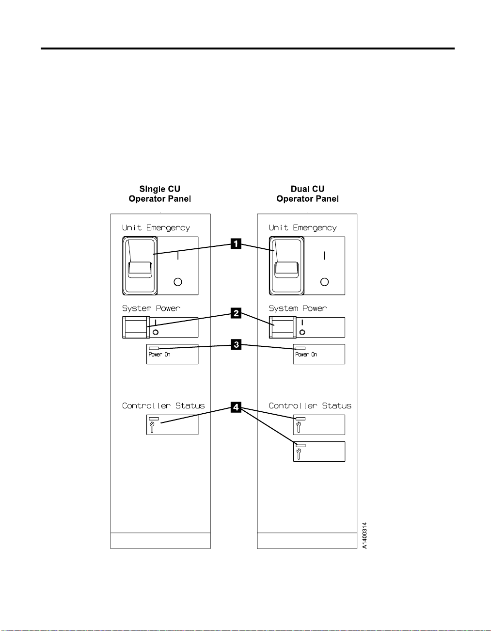
Figure 1. A14, C10, and C14 Operator Panel
© Copyright IBM Corp. 1995, 2001
3
Page 24

The following lists the components of the operator panel:
1. 1 Unit Emergency Switch
v With the unit emergency power off (EPO) switch in the up position, it is
turned “on” and the AC power is applied to the entire subsystem.
v With the EPO switch in the down position, it is turned “off” and all
power is removed from the subsystem.
2. 2 System Power Switch
v In the upward position, a power on sequence will initiate.
v In the downward position, a power off sequence will initiate.
3. 3 Power On LED
v The green LED, labeled “Power On”, has three functions:
a. Off.
When off, power is removed from the 3590 drives and controller.
b. On.
When on, power is applied to the drives and controller. If the
Controller Status LED is off, the unit is ready for use.
c. Flashing.
As power is applied or removed, and the unit is not ready for use,
the LED will flash.
4. 4 Controller Status LED
v The yellow LED, labeled “Controller Status”, has the following
functions:
a. Off.
The controller detects no fault.
b. On.
The controller detects an, as of yet, uncorrected fault.
c. Flashing.
If a potential fault is detected in the controller, the LED will flash
while waiting for the controller to correct the fault. If, after a set
period of time, the controller does not verify the error, the LED
indicator will remain on in a continuous state. On means that the
LED is not flashing.
Note: There are two Controller Status LEDs on a 3590 A50 or dual controller
4 3590 Operator Guide
configuration. The upper-status LED represents CU 1, and the lower
status LED represents CU 0.
Page 25

Chapter 3. Drive Operator Panel and Controls
Operator Panel Display
The operator panel provides a menu-driven operator and service interface
through a liquid crystal display assembly. Displays include operator menus
and service menus, device status, activities, error conditions, and data. See
Table 1 for panel displayed characters.
Table 1. Message-Display Symbols
Characters Symbols
Alphabetic A through Z
Numeric 0123456789
National “@$#”
Special “,./’ ()*&+−=”
Other “% :_<>?;øV │”
Note: A blank is considered a special character. All characters not listed in this table,
including nulls X'00', are displayed as blanks.
All lowercase alphabetic characters are converted to uppercase.
Several languages are available on the 3590. Regardless of country, the fonts
and translations for all of these languages are included in each microcode
release. Selection of the desired language is through the operator panel. To
change languages, the operator selects the desired language from the “Change
Language Menu” on page 45.
Operator tasks include making selections from the operator menus.
Unload Drive is a selection from the “Options Menu” on page 31. This menu
selection causes a loaded cartridge to be rewound and unloaded from the
device. The device will not accept any motion commands after you select
Unload Drive. If the device has data in the buffers, the device will
synchronize the data before rewinding. The host receives status appropriate to
the error if the device cannot synchronize the buffers. Selecting Unload Drive
immediately causes the device to become Not Ready; the operator panel
displays “UNLOADED.”
The device address is set by the operator through a menu selection (see “Set
Address Menu” on page 37 for SCSI and “Fibre Address Menu” on page 40 for
Fibre Channel.). Two selected SCSI or Fibre Channel IDs are associated with
one device interface. Each SCSI ID consists of one hexidecimal character that
© Copyright IBM Corp. 1995, 2001 5
Page 26

specifies the SCSI ID for that interface. (0 through 9 and A through F
correspond with bits 0 through 15 on the SCSI 2-byte wide interface.) Each
Fibre Channel ID consists of six hexidecimal characters that specify the Fibre
ID for that interface. At each power-on, this address is retrieved from
nonvolatile storage.
The online and offline selections control determines whether or not the device
is logically enabled to communicate on the interface. Use “Services Menu” on
page 33 to access this function. Figure 2 on page 7 shows the controls and the
indicator on the operator panel.
The Model E11 and B11 operator panel is mounted above the priority cell on
the Automated Cartridge Facility (ACF). The Model E11 and B11 mounts in a
rack (that is front-serviced) or in an A14 frame (that is rear-serviced).
For the Models B1A and E1A, which do not have an ACF, the operator panel
mounts in front of the drive. Models B1A and E1A mount in the 3494 tape
library as a rear-serviced device.
The operator panel has five push buttons; three are exposed and two are
hidden from view. When the display is in the normal position, the operator
can use the three exposed push buttons (up arrow, down arrow, and Enter).
When the panel is in the service position, the service representative can use
two additional push buttons (Reset and Change Mode). To put the panel in
the service position and expose the two buttons, the service representative
releases two finger latches on the back of the panel.
6 3590 Operator Guide
Page 27
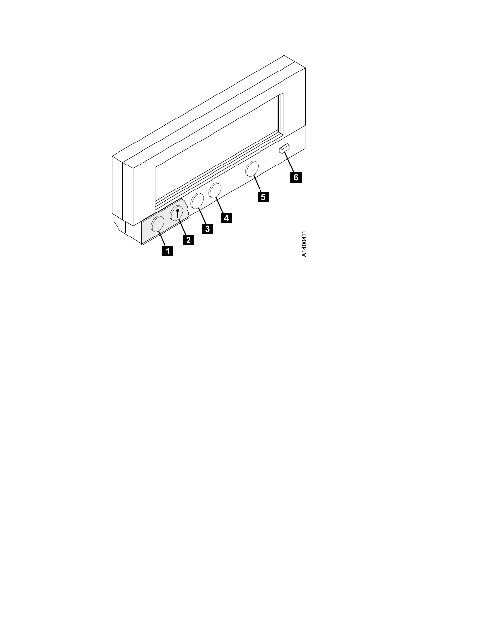
Figure 2. Operator Panel
From left to right in Figure 2, the push buttons and the indicator are as
follows:
Reset 1
A push button that allows the service representative to perform a
device power-on reset.
Note: It is recommended that all SCSI ports be taken offline before
resetting the drive. See “Services Menu” on page 33.
Change Mode 2
A push button that allows the service representative to toggle between
service representative mode and Normal mode. Service representative
mode can be selected at any time, but the mode will not become
active until the device completes all current operations. Normal mode
can be selected at any time. Selecting Normal mode returns the
operator panel menu to the Operator menu (that indicates status and
conditions). Service representative mode enables special menus on the
operator panel display not available to the operator in Normal mode.
Up Arrow 3
A push button that allows the operator or the service representative to
move the cursor arrow up through the menu options.
Down Arrow 4
A push button that allows the operator or the service representative to
move the cursor arrow down through the menu options.
Chapter 3. Drive Operator Panel and Controls
7
Page 28

Enter 5
A push button that allows the operator or the service representative to
select the menu option at the location of the cursor arrow.
Processor Check 6
An indicator LED that switches on for 10 to 20 seconds during a
normal power-on or a power-on reset. If no fault is detected, the LED
switches off. If the LED remains on, the 3590 requires service.
8 3590 Operator Guide
Page 29
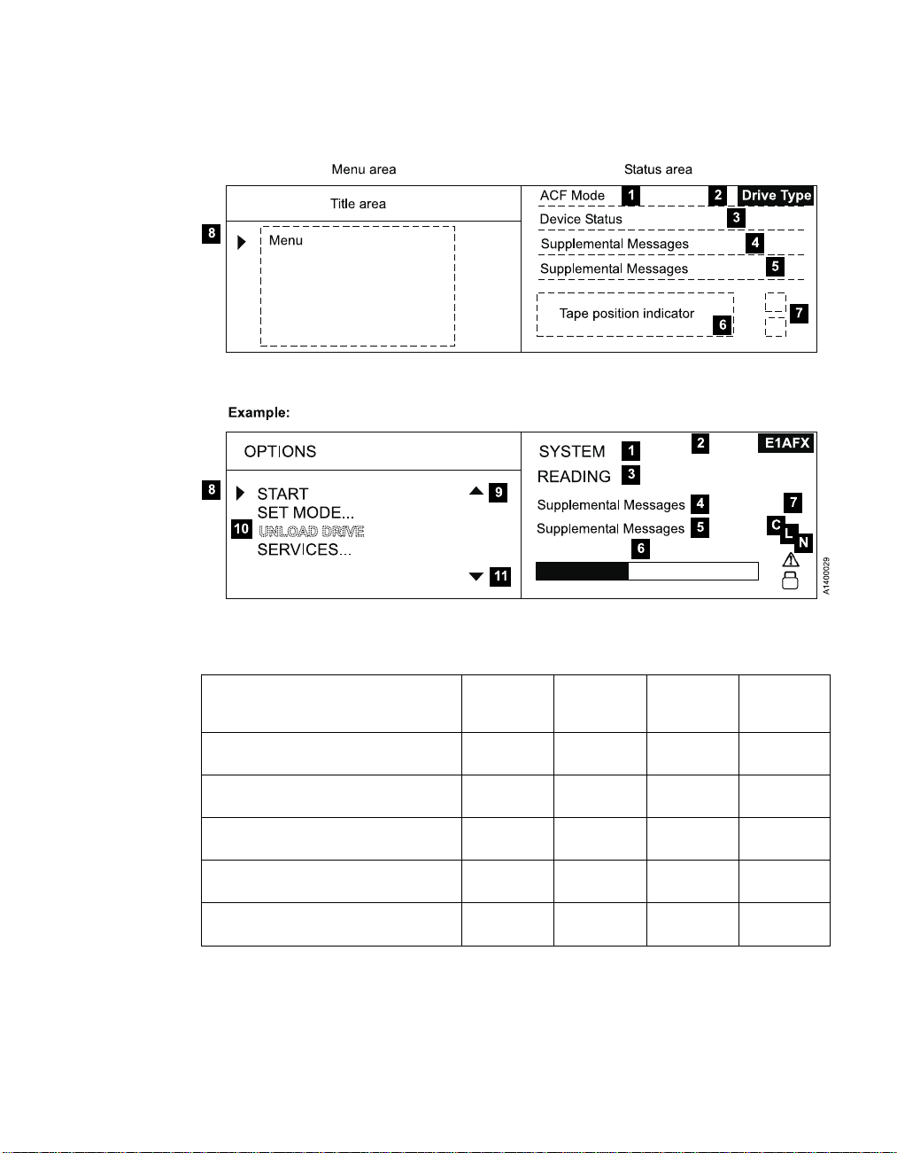
Table 2 identifies the various drive type indicators 2 of Figure 3 and Table 3
describes the panel areas it illustrates.
Figure 3. Options and Status Screen
Table 2. Drive Type Indicator
Drive Type 3590 Base ULTRA 3590E
Non-Extended High Performance
Cartridge / older microcode
Non-Extended High Performance
Cartridge / newer microcode ACF
Non-Extended High Performance
Cartridge / newer microcode non-ACF
Extended High Performance Cartridge
ACF
Extended High Performance Cartridge
non-ACF
3590E with
Fibre
Channel
ULTRA 3590E N/A
B11 B11-U E11 E11-F
B1A B1A-U E1A E1A-F
B11-X B11UX E11-X E11FX
B1A-X B1AUX E1A-X E1AFX
Chapter 3. Drive Operator Panel and Controls
9
Page 30

Table 3. Options and Status
Area Description
Displays as manual, automatic, system, accumulate, or random when the
ACF Mode 1
Drive Type 2 Table 2 provides the history of drive type indicators.
Drive and ACF
Status 3
ACF is installed.
When the operator changes modes, any current ACF operation (cartridges
in transit) are completed before the request is granted.
v Cleaning: A cleaning cartridge is in the device.
v Ready: A ready message is generated by the device when it is ready and
other higher-priority messages do not apply. The ready indicator is
displayed only when the transport is not moving tape. When ready or not
ready, the state of the device is the same to both SCSI busses.
v Ready at load point: The media is at the beginning of tape and the device
is ready.
v Accessing: The empty ACF transport is moving to a magazine position to
either check for an unused volume or to get a volume to load.
v Transferring: The device is moving a cartridge from the magazine or the
priority cell to the drive, or from the drive to the magazine or the
priority cell.
v Loading: The cartridge is being loaded into the drive.
v Locating: The device is moving the tape to a specific location.
v Reading: The device is reading data from the tape to the device buffer.
v Writing: The device is writing data to the tape from the device buffer.
v Erasing: The device is logically erasing data from the tape.
v Rewinding: The device is rewinding the tape to the beginning of the
logical volume.
v Unloading: The cartridge is being removed from the drive.
v ACF Disabled: The ACF cannot perform an operation; for example, the
magazine is not installed or the magazine was filled and the last
imported cartridge was returned to the priority cell.
v Blank Field: The ACF is inactive and the drive is not loaded.
10 3590 Operator Guide
Page 31

Table 3. Options and Status (continued)
Area Description
Messages:
v Area 4 and 5 is a dual-use area that can be used for prompts and
messages.
– SCSI messages include:
PORT0 ADDR=n ONLINE or OFFLINE.
PORT1 ADDR=n ONLINE or OFFLINE.(‘n’ can be in the range
0–F.)
For SCSI port 0 or 1 (PORT0 or PORT1), the last assigned SCSI
address (ADDR=n) is listed with each port’s online or offline status
(ONLINE or OFFLINE).
– Fibre Channel messages include:
Messages 4 and
Supplemental
Messages5
Tape position
Indicator 6
Status Icons 7
Cursor (>) 8
Up Arrow 9
= indicates use of a hard address
: indicates use of a soft address
Port ID=/:aa bb cd
Port0 ID=aa bb cd
Port1 ID=aa bb cd
aa = Fibre domain address
bb = Fibre area address
cd = AL_PA. This is the Arbitrated Loop Physical Address.
No connection
Port0 ID=-- -- --
Not communicating, or did not establish a connection.
Port0 ID=?? ?? ??
v Supplemental messages appear in the 2-line message area of the screens.
These messages include general information, user feedback for control
actions, and attention messages.
A graphic representation of the position of the tape for processing a
cartridge or rewinding a cartridge. See “Tape Position Indicator” on
page 14.
Displays different icons that represent the status of the device. See “File
Protected Icons” on page 14 and “Dump Icon” on page 15.
A symbol that moves when the operator presses the up or down arrow. The
item that is beside the cursor is chosen when the operator presses Enter.
A symbol displayed when the operator has menu choices above the
viewing area.
When the operator presses Enter, the item by the (cursor) is chosen.
Option 10
Down Arrow 11
If an item is dotted, such as UNLOAD DRIVE in a lighter font, it is not
available for use. If the operator presses Enter, the item is highlighted
temporarily and is not activated.
A symbol displayed when the operator has menu choices below the
viewing area.
Chapter 3. Drive Operator Panel and Controls
11
Page 32

Note: The 3590 tape drives that are capable to receive the Extended High
Performance Cartridge Tape are labeled 2x on the back of drive chassis.
For B Model drives, the 2x label is placed below the serial number
label. For Ultra and E Model drives, the 2x label is located below the
respective Ultra and E labels which, in turn, are located below the serial
number label. See Figure 4 for an illustration of the tape-icon label.
The 2x information is available in Table 3 on page 10.
Figure 4. 2x Label Icon
12 3590 Operator Guide
Page 33

Fiducials
Figure 5. Library Locating Fiducials
Figure 5 shows a B1A or E1A with a single fiducial 1. The fiducial is used
by cartridge-handling devices to locate and remember where the tape
subsystem device is installed. Do not cover or change the fiducial.
Drive Power
The power switch is located on the back of each device. This toggle switch
controls the distribution of ac power to the associated device. Certain
subsystem configurations have additional controls for distribution of ac power
to the device.
It is recommended that all SCSI ports be taken offline before powering off the
drive. See “Services Menu” on page 33.
Indicators and Icons
This section describes the indicators on the 3590.
Chapter 3. Drive Operator Panel and Controls
13
Page 34

Processor Check Indicator
The processor check indicator indicates that the model-unique
Licensed Internal Code is not following its normal sequence.
A symbol that looks like a wrench identifies the Processor
Check indicator on the operator panel. See Figure 2 on page 7
definitions for more details.
File Protected Icons
The status icons area of the operator panel displays the file-protected icons
(see Figure 3 on page 9).
The file-protected icon (physical) is a read only symbol that is
displayed when the thumbwheel on the cartridge is set to the
file-protected position.
#
#
#
#
#
#
#
#
#
#
#
#
#
#
The file-protected icon (logical) is a read only symbol that is displayed
when the 3590 receives the Mode Select command from a host
program that sets the volume to a logically write-protected state. Both
Write Once Read Many (WORM) and Persistent Write Protect status
leave a volume logically write-protected on subsequent loads. A
subsequent Mode Select turns off a persistent Write Protection, while
WORM cannot be turned off. Associated Write Protection persists only
while a logical volume is loaded or until a Mode Select changes the
protection status. Associated Write Protection status is lost when a
volume is unloaded or the device is powered-off. File protection is
temporarily inactive during volume loading and unloading when the
device updates the volume control region (VCR) on the tape. (During
this period of time, the icon reverts to file-unprotected). Refer to IBM
3590 High Performance Tape Subsystem Hardware Reference for details.
The file-unprotected icon is a read/write symbol that is displayed when
the thumbwheel on the cartridge is set to the not file-protected
position.
Tape Position Indicator
If the device is processing, the tape-position indicator provides the operator
with a graphical representation of the device’s position. The representation is
14 3590 Operator Guide
Page 35

relative to the beginning and end-of-volume. If the device is rewinding, the
tape-position indicator illustrates the beginning and end-of-tape. Logically
shortened tape is displayed normally, but the rate of change is faster than
normal length tapes.
Dump Icon
The status area of the operator panel displays the dump icon, (see Figure 3 on
page 9).
Attention: The dump is lost if you power off the drive.
Clean Icon
The status area of the operator panel displays a clean icon. (See Figure 3 on
page 9.)
The dump icon appears when a trace is available and remains on the
screen to indicate that the 3590 stores the trace data. The icon remains
on the screen until the 3590 power is turned off, a dump is read over
a SCSI port, or the dump is written to a tape.
When cartridge cleaning is required, the clean icon appears. It
displays in the same position as the dump icon, and the dump icon
overlays it until the CLEAN message displays. This icon alerts the
operator that a cleaning operation is requested.
Chapter 3. Drive Operator Panel and Controls 15
Page 36

Intervention Messages
The intervention screen displays intervention messages on the operator panel.
The intervention screen consists of an 8-character intervention message that is
displayed in a large font and a prompt. The prompt indicates that pressing
Enter allows access to the Options menu. The screen also has device status
information and a 2-line message area in the standard font. A drive type is
displayed (see Table 2 on page 9).
Figure 6 shows the intervention screen with an example of a Mount
command. The Mount command prompts the operator to mount a tape with
the volume serial (volser) 123567. In this example, M means mount and S
means scratch.
Figure 6. Intervention and Device Activity Messages
Table 4 describes messages that can be displayed for the 3590.
Table 4. Intervention and Device Activity Messages
Message Message Meaning
16 3590 Operator Guide
FID 1
FID 1 Messages
These messages indicate device errors that require operator and service
representative, or service representative only action. The device cannot
perform any tasks. See “Appendix B. FID Messages” on page 101.
ATTN Messages
Page 37

Table 4. Intervention and Device Activity Messages (continued)
Message Message Meaning
Attention
Mvolser The M prompts the operator to mount volser in the priority cell.
*CLEAN
Dvolser The D prompts the operator to remove volser from the priority cell.
FID 2
FID 3
FID 4
These messages indicate error conditions that operators can resolve, such as
Lock magazine. See Table 5 on page 24.
Routine Messages
This message prefixed with an asterisk (*) prompts the operator to put a
cleaning cartridge in the priority cell.
FID 2 Messages
These messages report a degraded device condition. The customer can
schedule a service call.
FID 3 Messages
These messages report a degraded device condition. The customer can
schedule a service call.
FID 4 Messages
These messages report a service circuitry failure. The customer can schedule a
service call.
Intervention messages are 1-part or 2-part messages. Two-part messages
consist of two 8-character message parts that alternate. The message types are
FID1 messages, attention messages, routine messages, FID2 messages, FID3
messages, and FID4 messages. A brief description of each message follows:
v FID1 Messages
The device generates a FID1 message when a hardware failure occurs
within the device. This error condition message has priority over all other
types of messages, and persists until corrected. Maintenance personnel uses
the FID code to identify the failing units within the device. (Menu
selections may overwrite FID messages temporarily.) Messages are in a bold
font.
The format of these messages is ‘FID1 xy’. ‘FID1’ indicates to the operator
that a failure occurred, and ‘xy’ is the replaceable portion of the device.
Figure 7 on page 18 shows an example of FID1 C6, which indicates that the
machine reel motor has a fault.
Chapter 3. Drive Operator Panel and Controls 17
Page 38

FID
12
>Operator Options
Figure 7. Error Message Example
The service representative makes note of the part identifier (FID) 1 and
the severity code 2. The service representative then uses the FID number
3 to enter the Maintenance Package. The message area of 4, 5, and
6 hex data is support information to help determine if model-unique
Licensed Internal Code causes the fault.
v Attention Messages
Attention (ATTN) messages indicate error conditions that customer
personnel may be able to resolve. For example, the operator can correct the
ATTN ACF message with a supplemental message of Magazine not locked.
v Routine Messages
Routine Messages consist of messages that are received from the host
through the SCSI Display Message command (for example, Mount), and
messages from the device (for example, *CLEAN).
To generate the Clean message, the device monitors the number of
megabytes that are processed and the number of nonpermanent errors for
each drive. When either of these factors reaches a threshold, the device
displays a Clean message. The clean message is maintained across device
power-on reset conditions.
The routine messages that are received through the Display Message
command consist of mount messages, demount messages, and general
(custom) messages.
The routine messages usually refer to the priority cell. Actions that are
automatically handled by the ACF usually occur without the display of an
operator message. The initiator can generate these messages. If, however,
the device microcode detects that the ACF will automatically perform the
action requested, any corresponding message is suppressed.
v FID2 Messages
A FID2 message indicates that the drive is in a degraded state. For example,
FID2 E4 could indicate that one SCSI port has a fault. The drive is usable,
but is in a less available state.
v FID3 Messages
A FID3 message indicates that the drive is in a degraded state. The drive is
usable, but is in a more available state than for a FID2 type of fault.
1C6
3
456
18 3590 Operator Guide
Page 39

v FID4 Messages
A FID4 message indicates that some service circuitry failed. For example,
FID4 E4 could indicate that a parity-check circuit failed.
Message Priority and Display Rules
This section describes message priorities and their creation, deletion, display,
and storage.
Message Action Term Definitions
This description defines the following message action terms:
Display
Display means to present a message on the operator panel display.
Store Store means to remove the message from the operator panel display.
The device holds the message for future redisplay. Overlaying it with
another message or erasing it from the display may store a message.
Overlay
Overlay means to substitute the message on the display with another
message or menu while holding the original message in stored form.
The undeleted original message is stored.
If not first replaced or deleted, messages (such as routine messages
that are overlaid when the Enter button is pressed) are redisplayed
after a short time interval.
Replace
Replace means to delete a message and substitute a new message.
Displayed or stored message are replaceable.
Delete Delete means to remove the message from the device and the operator
panel display. A device buffer log, of the condition that caused the
message, is holdable. It is not restoreable, but the function that
generated the original message may regenerate it.
Ignore The drive may receive certain messages and not pass them to the
display. Refer to these messages as ignored.
Message Priorities
Message priorities determine which types of intervention messages will
overlay other types of messages. Higher priority messages overlay lower
priority messages. A lower priority message, that is stored, will display when
deleting or storing a higher priority message. The 5 message types follow,
listed from highest to lowest priority.
1. FID 1
2. Attention (ATTN)
3. Routine Messages (Mount, Demount, Demount/Mount, Clean, and
General)
Chapter 3. Drive Operator Panel and Controls 19
Page 40

4. FID 2
5. FID 3
6. FID 4
Note: “Message Life Cycle Rules” describes the priority relationships between
individual Routine Messages.
Message Life Cycle Rules
“Message life cycle rules” are the rules that govern creating, replacing,
displaying, storing, and deleting messages.
FID 1:
v Creation: A FID 1 is created when the model-unique Licensed Internal Code
detects a permanent error that removes the device from the customer’s
application and which will require operator action or service representative
maintenance before the device is again available. FID 1 messages can be
replaced by other FID 1 messages.
v Displayed: FID 1 messages are displayed when created. All FID messages
will have the form “FIDnmm”, where n is 1 through 4 and mm is the
specific FID code.
v Deletion: FID 1 messages are deleted during the power cycle. If a FID 1
message displays, and the Enter button is pressed, the FID 1 message
deletes. Also, new FID 1 messages delete old FID 1 messages.
Attention Messages:
v Creation: When the model-unique Licensed Internal Code detects an error
that the operator of the device can fix, it creates an Attention message. An
example is an ACF error that requires the tape to unload. Attention
messages are ATTN DRV and ATTN ACF.
v Stored: When a FID 1 message overlays an Attention message, the code
stores the Attention message. When the code deletes the displayed FID 1
message, it displays the stored Attention message.
v Deletion: An Attention message is deleted when the Enter key is pressed or
when power is cycled. Pressing the Reset button deletes it. The Attention
message generates again if the condition has not been resolved.
Routine Messages—Mount:
v Creation: A Mount message is created when a SCSI Display Message
command is received that requests a Mount message. If a cartridge is
loaded in the drive, it ignores the Mount message.
If a Mount message is received while an earlier Mount message exists, the
second Mount message replaces the earlier one.
This command also deletes any General messages and deletes the mount
portion of previous Demount/Mount messages.
20 3590 Operator Guide
Page 41

v Stored: A Mount message is stored when a cartridge is unloading and a
Demount message is displayed.
v Displayed: A stored Mount message is displayed when the previous
Demount message is deleted. Previous Demount messages are deleted
when the accessor removes a cartridge from the loader.
v Deletion: The device removes a Mount message from the display when it
initiates a cartridge load. When the device transitions to the Ready state
(stored or displayed message), it deletes the Mount message.
Routine Messages—Demount:
v Creation: A Demount message is created when a SCSI Display Message
command is received that requests a Demount message. A Demount
message is ignored if it is received when no cartridge is loaded.
If a Demount message is received when an earlier Demount message exists
and the cartridge is loaded, the new Demount message replaces the earlier
one.
This command also deletes any general messages and deletes any previous
Demount/Mount messages.
v Deletion: A Demount message is deleted when the accessor removes a
cartridge from the loader.
Routine Messages—Combined Demount/Mount:
v Creation: A Demount/Mount message is created when a Display Message
command is received that requests a Demount/Mount message. If the
device is not loaded when the Demount/Mount message is received, the
mount portion is displayed and the Demount portion of the message is
deleted.
If the device is loaded when the Demount/Mount message is received, the
Demount portion is displayed.
If a Demount/Mount message is received when an earlier Demount/Mount
message exists, the second Demount/Mount message replaces the earlier
one.
This command also deletes any General messages and deletes any previous
Demount/Mount messages.
v Stored: If a cartridge is loaded, the mount portion of the Demount/Mount
message is stored.
v Displayed: After the demount portion of the message is deleted, the mount
portion of the message is displayed. When a cartridge is loaded, and the
drive enters the Ready state, it deletes the mount portion of a stored or
displayed message.
v Deletion: When the device transitions to the Ready state, the mount
message deletes if the device is not loaded. The message also deletes if the
Chapter 3. Drive Operator Panel and Controls 21
Page 42

mount portion of the demount/mount message is displayed. For a loaded
cartridge, the demount portion of the message is deleted when the accessor
removes a cartridge from the loader.
A message control of “100” (alternate message) will cause the demount and
mount messages to alternate as long as a cartridge is loaded. Demount is
deleted when a cartridge is unloaded.
Routine Messages—General (Custom):
v Creation: A General message is created when a Display Message is received
that requests a General message. A General message received while an
earlier General message exists replaces the first General message.
v Displayed: A General message displays when it is created.
v Deletion: When the device activity changes, or the Enter key is pressed, or
when any other Routine Message enters a display mode a General message
is deleted.
Routine Messages—Clean:
v Creation: When the device microcode detects that the device needs
cleaning, it creates a Clean message. This is checked at every unload. When
a diagnostic routine detects the need for cleaning, it may also create a Clean
message.
v Stored: When created, a Clean message is stored. When the Enter button is
pressed, a displayed Clean message is stored. It is overlaid by another
stored message, or if no other intervention message is present, by the
Options/Status screen.
v Displayed: When the device is unloaded, a Clean message is displayed.
v Deletion: When the device is loaded, a Clean message is deleted. This
occurs regardless of whether the cartridge loaded was a data cartridge or a
cleaner cartridge. When the currently-loaded cartridge is unloaded, another
Clean message will be generated if the device was not cleaned. A Clean
message is also deleted when the device goes through a power-off to
power-on cycle or when the operator panel Reset button is pressed.
Combination Rules for Routine Messages: When any message enters display
mode, it is combined with any other messages that already may be displayed
in a sequence of messages. Newly-displayed messages are appended at the
end of the message sequence.
In most cases, the message sequence will not grow beyond 2 or 3 alternating
messages. It can grow to a 4- or 5-part message if a Clean message is also
displayed. This situation happens when 2-part mount messages, 2-part
demount messages, or combined demount/mount messages are followed by a
2-part General message.
22 3590 Operator Guide
Page 43

FID 2:
v Creation: A FID 2 message is created when the device microcode detects a
permanent failure of a serious nature that puts the device in a degraded
state. The drive can still be used, but it is in a less available state. If a
subsequent FID 2 message is generated, it replaces any earlier FID 2
messages.
v Stored: A FID 2 message is stored and overlaid when a higher priority
message is displayed.
v Displayed: A FID 2 message is displayed when it is not overlaid by a
higher priority message.
v Deletion: FID 2 messages are deleted by a power cycle or the generation of
a new FID 2 message.
FID 3:
v Creation: A FID 3 message is created when the device microcode detects a
permanent failure of a moderate nature that puts the device in a degraded
state. The drive can still be used, but is in a less available state. If a
subsequent FID 3 message is generated, it will replace the earlier FID 3
messages.
v Stored: A FID 3 message is stored and overlaid when a higher priority
message is displayed.
v Displayed: A FID 3 message is displayed when it is not overlaid by a
higher priority message.
v Deletion: FID 3 messages are deleted by a power cycle or the generation of
a new FID 3 message.
FID 4:
v Creation: A FID 4 is created when the device microcode detects a
permanent failure in service circuitry (circuitry that is used only to check
functional circuitry). An example of a FID 4 is when JTAG circuitry breaks.
v Stored: Any higher priority message (FID 1, Attention, Routine Message,
FID 2, or FID 3) will cause a FID 4 message to be stored and overlaid.
When a FID 4 message is displayed and the Enter button is pressed, the
FID 4 message will be deleted.
v Displayed: A FID 4 message is displayed when it is not overlaid by a
higher priority message.
v Deletion: FID 4 messages are deleted by a power cycle or the generation of
a new FID 4 message.
FID and ATTN Supplemental Messages
Table 5 on page 24 lists messages that are sent to the operator panel and the
appropriate operator action. See Figure 6 on page 16 for the location of the
supplemental messages.
Chapter 3. Drive Operator Panel and Controls 23
Page 44

Table 5. Operator Messages
Message Operator Response
ACF IRQ FAULT Service representative intervention required.
ACF MESSAGE
MISSING
Service representative intervention required.
Operator intervention required.
ACF NOT ENABLED
WIPE FAILED
CLEAN REQUIRED
CALL FOR SERVICE
CLEAR PICKER PATH
ERP RELOAD
FAILURE
Ensure cartridge is in ACF import position. For more information, see
“Cartridge Magazine Positions” on page 52 and “Chapter 6. Identifying
Subsystem Problems” on page 73.
Operator intervention required
A reformatted tape from 128-track to 256-track, or from 256-track to
128-track, failed. To correct this error, attempt to reformat the tape back
to its original tack configuration, or remove the tape from the library.
The Clean Required message indicates that the drive is fenced, and
will not be usable until a cleaner cartridge is loaded. This happens if a
customer ignores cleaner messages for a long time.
Operator Action Required
The tape subsystem experienced a problem that requires service
intervention. Note any message numbers and call your service
representative. See Figure 7 on page 18.
Operator intervention or possible service representative corrective
action required.
Operator action required:
The tape subsystem detects the presence of a possible blockage in the
cartridge path, such as in the magazine or in the priority cell. Check
the position of all cartridges to ensure they are properly positioned in
the magazine and in the priority cell. (A cartridge that extends too far
into the magazine in the import position or perhaps a damaged
cartridge could cause this error.) If this condition is not cleared,
remove the magazine and look for any obvious obstructions. Replace
the magazine in the ACF. If the condition persists or a FID message is
displayed, report any FID codes to your service representative.
The ERP Reload Failure message should be treated the same as the
LOAD ERROR message.
Operator intervention required:
EXTRA CARTRIDGE
24 3590 Operator Guide
The tape subsystem loaded a cartridge from the magazine and
detected that another cartridge was placed in its home position. The
tape subsystem will attempt to place the now displaced cartridge in
the priority cell awaiting operator action. If the priority cell is full, it
will eject the cartridge when the priority slot is unloaded. If the
priority cell is empty and the cartridge fails to eject, a problem may
exist with the priority cell that may require possible service
representative corrective action.
Ensure that no cartridge has been inserted into an ‘in use’ cell (green
LED on).
Page 45

Table 5. Operator Messages (continued)
Message Operator Response
FEED OVERCURRENT
FSC TRAP TAKEN Service representative intervention required.
HEAD CALIB FAILED.
INVALID CARTRIDGE
LOAD ERROR
LOCK ERROR
LOCK MAGAZINE
Service representative intervention required.
Report any FID codes to your service representative.
Operator intervention or possible service representative corrective
action required.
Select Unload on the operator panel and press Enter. If the device fails
to unload the cartridge, note any FID messages and call your service
representative.
Operator action required.
An invalid media type is detected. The invalid media must be replaced
with either a 3590 High Performance Cartridge Tape or a 3590
Extended High Performance Cartridge Tape. An Extended High
Performance Cartridge Tape will cause an invalid cartridge message if
it is loaded into a drive that is not Extended High Performance
Cartridge Tape capable.
Operator intervention or possible service representative corrective
action required.
Select Unload on the operator panel and press Enter. If the device fails
to unload the cartridge, note any FID messages and call your service
representative.
1. Ensure that the cartridge is not broken and the leader block is
intact. See “Damaged Cartridges” on page 87 and “Leader Block
Replacement” on page 90.
2. Ensure that the cartridge is a 3590 compatible-type cartridge. Also,
check the location of the tape and the leader block.
Operator intervention required:
Try locking or unlocking the magazine.
Try another magazine.
Check ACF mode.
Select correct ACF mode.
For more information, see “Chapter 4. Automatic Cartridge Facility
(ACF) and Magazine” on page 49.
Operator intervention required:
Lock the magazine by pressing the lock button on the left side of the
front of the ACF.
Chapter 3. Drive Operator Panel and Controls
25
Page 46

Table 5. Operator Messages (continued)
Message Operator Response
Operator action required:
When the tape subsystem placed a cartridge in the magazine, the
cartridge was placed either beyond or in front of the Export position.
When the cartridge is not in the true Export position, it is possible that
MAGAZINE EXPORT
ER
MAGAZINE FULL
MAGAZINE LOCKED
a cartridge placed in front of the Export position may unexpectedly be
reused. When a cartridge is placed beyond the Export position, and
not in the true Export position, it is possible that the cartridge will not
be detected in the magazine.
Correct either of these conditions by removing the magazine from the
ACF, checking that all cartridges are correctly positioned, and replace
the magazine into the ACF.
Operator action required:
Empty the magazine or replace it with another magazine.
Operator action required:
Same as UNLOCK MAGAZINE.
Service representative intervention may be required.
Operator action required:
MOVE ERROR
NO CARTRIDGE
Ensure that the cartridge is not damaged or broken and that the
cartridge is a 3590 cartridge. See “Damaged Cartridges” on page 87.
An error occurred in the ACF. Check the message display and report
any FID codes to your service representative.
In certain modes, operations may continue by using the priority cell.
Operator intervention or possible service representative corrective
action required.
Operator action required:
The tape subsystem detects the presence of cartridges but cannot find a
cartridge in either the magazine or the priority cell. Check the position
of all the cartridges to ensure they are properly positioned in the
magazine and the priority cell. Press Start. If this condition is not
cleared, remove and replace the magazine in the ACF. If the condition
persists or a FID message is displayed, report any FID codes to your
service representative.
26 3590 Operator Guide
Page 47

Table 5. Operator Messages (continued)
Message Operator Response
Operator action required:
The tape subsystem does not detect a magazine in the ACF. If a
magazine is installed in the ACF, clear the condition by removing and
then replacing the magazine in the ACF. Try another or a different
NO MAGAZINE
PICKER
OVERCURRENT
PINCH 1 ERROR
PINCH 2 ERROR
PINCH
OVERCURRENT
magazine. If the condition persists or a FID message is displayed,
report any FID codes to your service representative.
The operator can use the tape subsystem by loading cartridges into the
priority cell in all modes except in Random mode. Random mode
requires a magazine to be installed and locked.
Service representative intervention required.
Report any FID codes to your service representative.
Service representative intervention may be required.
This failure may be caused by a dirty cartridge. Look for any
contamination on the sides of the cartridge that could cause the pinch
rollers to slip. Clean or replace the cartridge.
Note: Do not ship magazines with cartridges loaded. The cartridges
will vibrate in the magazine slots resulting in contamination on the
sides of the cartridges that may cause this failure.
Service representative intervention required.
Report any FID codes to your service representative.
Operator action required:
PRIORITY EXPORT ER
TEMP AC PWR DIP
When the tape subsystem placed a cartridge in the priority cell, the
cartridge was placed either beyond or in front of the Export position.
When the cartridge is not in the Export position, it is possible that a
cartridge placed in front of the Export position may unexpectedly be
reused. When a cartridge is placed beyond the Export position, it is
possible that the cartridge will not be detected in the priority cell.
Correct either of these conditions by removing the cartridge from the
priority cell.
Operator intervention or possible service representative corrective
action required.
Select Unload on the operator panel and press Enter. If the device fails
to unload the cartridge, note any FID messages and call your service
representative.
Chapter 3. Drive Operator Panel and Controls
27
Page 48

Table 5. Operator Messages (continued)
Message Operator Response
Operator intervention or possible service representative corrective
action required.
TENSION DROPPED
TRANSPORT FULL
UNLOAD ERROR
Select Unload on the operator panel and press Enter. If the device fails
to unload the cartridge, note any FID messages and call your service
representative.
1. Operator intervention required.
2. The drive attempted to unload a cartridge, but had no place to put
it. The magazine handle was moved while the drive was unloading
a cartridge, or, a tape was present in the slot where ACF transport
tried to unload, so tape cartridge is still left in transport. Action:
Do not remove the magazine while the status area on the operator
panel is displaying Transferring.
3. Unload priority slot.
4. Service representative intervention may be required.
Operator intervention or possible service representative corrective
action required.
Select Unload on the operator panel and press Enter. If the device fails
to unload the cartridge, note any FID messages and call your service
representative.
1. Ensure that the cartridge is not broken and the leader block is
intact. See “Damaged Cartridges” on page 87 and “Leader Block
Replacement” on page 90.
2. Ensure that the cartridge is a 3590 compatible-type cartridge. Also,
check the location of the tape and the leader block.
Operator action required:
UNLOCK MAGAZINE
WRONG MODE
Operator Panel Menus
The operator panel allows information to be passed from the device to the
operator and back to the device. The operator and service representative can
be presented menu-driven options for device operation. Examples include the
display of SCSI port addresses and operator panel languages.
Options that are unavailable are displayed in a lighter dotted font, and cannot
be selected. The example in Figure 8 on page 29 shows the Unload Drive
28 3590 Operator Guide
Remove and replace the magazine. Try another magazine. If the
condition persists or a FID message is displayed, report any FID codes
to your service representative.
Operator action required:
ACF mode incorrect for the command. For more information, see
“Modes of Operation” on page 55.
Page 49

option 1 when there is no cartridge in the device. The Unload Drive option
2 shows the darker font, which indicates that it can be selected.
Figure 8. Example of Selectable Options
If you move the cursor ()to1 and press Enter, the selection responds with
the normal font 2 momentarily. It then returns to the lighter font. The 3590
will not perform any action.
Chapter 3. Drive Operator Panel and Controls
29
Page 50

Operator Flow Chart
Figure 9 shows the operator menus with panel functions.
Figure 9. Operator Menus
30 3590 Operator Guide
Page 51

Operator Menus
Operator menus are available at the successful completion of the power-on
self-test (POST).
Options Menu
Table 6 shows the Options menu.
Table 6. Options
Function Next Menu
Start/Allow Load
(Model C12/C14
only)
Set ACF Mode... “Set ACF Mode Menu” on page 32
Unload Drive —
Services... “Services Menu” on page 33
Note: Supplemental Message Line 1: <none> Supplemental Message Line 2: <none>
Start Enables the ACF on Models E11 or B11. This function cannot be
selected on Models E1A or B1A.
Allow Load
Allows loading cartridges when the 3590 Model C12 or C14 is in
manual mode.
—
Set ACF Mode
Sets the ACF mode for Models E11 and B11.
Unload Drive
Causes the device to rewind and to unload the cartridge in the device.
Services
Allows the operator to perform configuration tasks, such as setting the
SCSI online and offline.
Chapter 3. Drive Operator Panel and Controls 31
Page 52

Set ACF Mode Menu
Table 7 shows the Set ACF Mode menu.
Table 7. Set ACF Mode
Function Next Menu
Cancel “Options Menu” on page 31
System “Options Menu” on page 31
Automatic “Options Menu” on page 31
Manual “Options Menu” on page 31
Accumulate “Options Menu” on page 31
Random (B11 model
only)
Random 2-LUN “Options Menu” on page 31
Note: Supplemental Message Line 1: <none> Supplemental Message Line 2: <none>
“Options Menu” on page 31
Cancel
Causes the “Options Menu” on page 31 to appear.
System
Places cartridge feeding under system control.
Automatic
Takes the cartridges that are loaded in the import position of the
magazine and automatically feeds one cartridge after another.
Automatic mode does this until the entire magazine is processed.
Manual
Accumulate
Random
Random 2-LUN
32 3590 Operator Guide
Feeds a cartridge into the drive.
Takes the cartridge from the priority cell and places it in the drive. It
unloads cartridges from the drive to the magazine.
Places all the cartridges in the import position. The magazine must be
locked. This option is only available on B11 models.
Places all the cartridges in the import position. The magazine must be
locked. This option may need to be selected depending on the host
software.
Page 53

Services Menu
Table 8 shows the Services menu.
Table 8. Services
Function Next Menu
Cancel “Options Menu” on page 31
Set Online. “Set Online Menu” on page 35
Set Offline. “Set Offline Menu” on page 36
Set Address... (SCSI
Attached Drives
Only)
Fibre Address...
(Fibre Attached
Drives Only)
Change Language... “Change Language Menu” on page 45
Statistics... “Statistics Menu” on page 46
Refresh Tape —
Microcode Level Figure 10 on page 34, then after selection, to “Services Menu”
Reset Drive Figure 11 on page 35, then after selection, to “Services Menu”
Force Error Dump Figure 11 on page 35, then after selection, to “Services Menu”
Note: Supplemental Message Lines: <none>
“Set Address Menu” on page 37
“Fibre Address Menu” on page 40
Cancel
Causes the “Options Menu” on page 31 to appear.
Set Online
Logically enables the device to communicate on the SCSI bus. Activate
Set Online at the device first, then have the host place the device
online (vary online).
Set Offline
Logically disables the device from the SCSI bus. Select Set Offline only
after the host has taken the device offline (vary offline) first.
Set Address
Provides the two SCSI addresses to be selected; one address that is
associated with each device interface. Each address consists of one
hexadecimal digit that specifies the SCSI address for that interface.
After the address is set, change the host information to include the
correct addresses.
Fibre Address
Provide the two Fibre Arbitrated Loop Physical Addresses (AL_PA) to
be selected; one address that is associated with each device interface.
Chapter 3. Drive Operator Panel and Controls 33
Page 54

Each AL_PA. consists of two hexadecimal numbers. After each adress
is set, the device will automatically run Loop Initialization (LIP).
Change Language
Allows the operator to select the operator panel language.
Statistics
Displays the number of times certain events occurred.
Refresh Tape
This option is selectable only when a tape is loaded. It will locate to
the end of the tape and rewind to its beginning.
Microcode Level
Displays the microcode EC level that is in DRAM. Figure 10 shows an
example.
MICROCODE LEVEL
CANCEL
EC aaaaaaa
LINK bbcd_ddd
Legend Description
aaaaaaa
Engineering change level
bb Product identifier
c Link identifier
d_ddd Link number
Figure 10. Microcode Level Menu
Reset Drive
Force Error Dump
Choosing Reset Drive or Force Error Dump causes the menu that is shown in
Figure 11 on page 35 to appear.
34 3590 Operator Guide
Aborts the operation and causes the drive code to restart. If dump
data is in the drive, it is not lost.
Note: Current operation (for example Locate) will be completed before
Reset Drive runs. This may cause a delay before Reset Drive is run.
Aborts the operation, causes a recovery of the functional code, and
forces a microcode dump. After getting the dump, select Reset Drive.
This selection is normally used because of specific requests from
support personnel.
Page 55

Figure 11. Confirmation Menu
Cancel
Causes the model-unique Licensed Internal Code to ignore the
selection and causes the Services menu to appear.
Proceed
Causes the model-unique Licensed Internal Code to perform the
operation that is chosen (Reset Drive or Force Error Dump) from the
Services menu.
Set Online Menu
Table 9 shows the Set Online menu.
Table 9. Set Online
Function Next Menu
Cancel “Services Menu” on page 33
Port 0 “Options Menu” on page 31
Port 1 “Options Menu” on page 31
Both “Options Menu” on page 31
Note: Supplemental Message Line 1: <none> Supplemental Message Line 2: <none>
Cancel
Causes the “Services Menu” on page 33 to appear.
Port 0 Causes SCSI port 0 to be set online.
Port 1 Causes SCSI port 1 to be set online.
Both Causes SCSI port 0 and SCSI port 1 to be set online.
Note: The host must also vary the device online.
Chapter 3. Drive Operator Panel and Controls
35
Page 56

Set Offline Menu
Table 10 shows the Set Offline menu.
Table 10. Set Offline
Function Next Menu
Cancel “Services Menu” on page 33
Port 0
Port 1
Both “Confirm Offline Menu” on page 37
Note: Supplemental Message Line 1: <none> Supplemental Message Line 2: <none>
“Confirm Offline Menu” on page 37 or “Options Menu” on
page 31
“Confirm Offline Menu” on page 37 or “Options Menu” on
page 31
Cancel
Causes the “Services Menu” on page 33 to appear.
Port 0 Causes SCSI port 0 to be set offline.
Port 1 Causes SCSI port 1 to be set offline.
Both Causes SCSI port 0 and SCSI port 1 to be set offline.
If the device interface successfully goes offline, the “Options Menu” on
page 31 appears, otherwise the operator can proceed to “Confirm Offline
Menu” on page 37 for further options.
Attention: The device should be quiesced by the host (vary the device offline)
before taking the device offline or before powering off the device.
Note: The device must complete all activity currently on the interface before
36 3590 Operator Guide
it can go offline. If the device or the initiator cannot complete activity
before going offline, “Confirm Offline Menu” on page 37 is displayed.
This allows the operator an override and forces the ports offline.
Page 57

Confirm Offline Menu
Table 11 shows the Confirm Offline menu.
Table 11. Confirm Offline
Function Next Menu
Cancel “Set Offline Menu” on page 36
Proceed “Options Menu” on page 31
Note: Supplemental Message Line 1: Caution: Data loss Supplemental Message Line
2: risk
Cancel
Cancels the offline request and causes the “Set Offline Menu” on
page 36 to appear.
Proceed
Forces the ports offline. If write activity exists, any write data in the
device is lost. The Proceed option causes the job to end.
Attention: The device should be quiesced by the host (vary the device
offline) before taking the device offline or before powering off the
device.
Note: Current operation (for example Locate) will be completed before
Proceed executes. This may cause a delay before Proceed is executed.
Set Address Menu
Table 12 shows the Set Address menu.
Table 12. Set Address
Function Next Menu
Cancel “Services Menu” on page 33
Port 0... “Set Port 0 Address Menu” on page 38
Port 1... “Set Port 1 Address Menu” on page 39
Note: Supplemental Message Line 1: Change made after Supplemental Message Line
2: unload and reset
Cancel
Causes the “Services Menu” on page 33 to appear.
Port 0 Causes the “Set Port 0 Address Menu” on page 38 to appear.
Port 1 Causes the “Set Port 1 Address Menu” on page 39 to appear.
Note: The address must be defined at the host also.
Chapter 3. Drive Operator Panel and Controls 37
Page 58

Set Port 0 Address Menu
Table 13 shows the Set Port 0 Address menu.
Table 13. Set Port 0 Address
Function Next Menu
Cancel “Set Address Menu” on page 37
0 “Options Menu” on page 31
1 “Options Menu” on page 31
... “Options Menu” on page 31
F “Options Menu” on page 31
Note: Supplemental Message Line 1: Change made after Supplemental Message Line
2: next power on
Cancel
Causes the “Set Address Menu” on page 37 to appear.
<value>
Allows the operator to set the address of SCSI port 0. The value can
be from 0–15 (16 addresses).
Note: You must select Reset Drive from the Services menu, press the
Reset push button or switch off power to the device, then
switch on power to activate the new address.
38 3590 Operator Guide
Page 59

Set Port 1 Address Menu
Table 14 shows the Set Port 1 Address menu.
Table 14. Set Port 1 Address
Function Next Menu
Cancel “Set Address Menu” on page 37
0 “Options Menu” on page 31
1 “Options Menu” on page 31
... “Options Menu” on page 31
F “Options Menu” on page 31
Note: Supplemental Message Line 1: Change made after Supplemental Message Line
2: next power on
Cancel
Causes the “Set Address Menu” on page 37 to appear.
<value>
Allows the operator to set the address of SCSI port 1. The value can
be from 0–15 (16 addresses).
Note: You must select Reset Drive from the Services menu, press the
Reset push button or switch off power to the device, then
switch on power to activate the new address.
Chapter 3. Drive Operator Panel and Controls 39
Page 60

Fibre Address Menu
Table 15 shows the Fibre Address menu.
Table 15. Set Address
Function Next Menu
Cancel “Services Menu” on page 33
Show Node Names “Show Node Name Menu”
Show Port Names “Show Port Names Menu” on page 41
Set Port 0... “Set Port 0 Fibre Address Menu” on page 42
Set Port 1... “Set Port 1 Fibre Address Menu” on page 43
Cancel Causes the “Services Menu” on page 33 to
appear.
Show Node Name Causes the “Show Node Name Menu” to
appear.
Show Port Names Causes the “Show Port Names Menu” on
page 41 to appear.
Set Port 0 Causes the “Set Port 0 Fibre Address Menu”
on page 42 to appear.
Set Port 1 Causes the “Set Port 1 Fibre Address Menu”
on page 43 to appear.
Show Node Name Menu
Table 16 shows the Show Node Name menu.
Table 16. Show Node Name
Function Next Menu
Cancel “Fibre Address Menu”
Node Name
0123456789ABCDEF
(16 character #)
Cancel Selecting this function causes the “Set Address Menu” on
Node Name 0123456789ABCDEF The number that appears is a unique
40 3590 Operator Guide
“Fibre Address Menu”
page 37 to appear.
address for the logical unit in the drive. The address uses the
World Wide ID convention which is a sixteen character
number.
Page 61

Show Port Names Menu
Table 17 shows the Show Port Names menu.
Table 17. Show Port Names
Function Next Menu
Cancel “Fibre Address Menu” on page 40
Port 0 Names
0123456789ABCDEF
(16 character #)
Port 1 Names
0123456789ABCDEF
(16 character #)
“Fibre Address Menu” on page 40
“Fibre Address Menu” on page 40
Cancel
Selecting this function causes the “Fibre Address Menu” on page 40 to
appear.
Port 0 Name
The number that appears is a unique address for the physical port.
The address uses the World Wide ID convention which is a sixteen
character number.
Port 1 Name
The number that appears is a unique address for the physical port.
The address uses the World Wide ID convention which is a sixteen
character number.
Chapter 3. Drive Operator Panel and Controls 41
Page 62

Set Port 0 Fibre Address Menu
Table 18 shows the Set Port 0 Fibre Address menu.
Table 18. Set Port 0 Fibre Address
Function Next Menu
Cancel “Fibre Address Menu” on page 40
Set Hard Address “Set Hard Address Menu” on page 44
Use Soft Address “Use Soft Address Menu” on page 45
Cancel
Causes the “Fibre Address Menu” on page 40 to appear.
Set Hard Address
Causes the “Set Hard Address Menu” on page 44 to appear. Selecting
the hard address option allows the operator to set the Arbitrated Loop
Physical Address (AL_PA). A higher number designates lower priority.
This is the standard method to set the address. Use this method
unless specifically instructed otherwise.
Use Soft Address
Causes the “Use Soft Address Menu” on page 45 to appear. The soft
address feature allows the drive to arbitrate the AL_PA number with
other fibre devices.
42 3590 Operator Guide
Page 63

Set Port 1 Fibre Address Menu
Table 19 shows the Set Port 1 Fibre Address menu.
Table 19. Set Port 0 Fibre Address
Function Next Menu
Cancel “Fibre Address Menu” on page 40
Set Hard Address “Set Hard Address Menu” on page 44
Use Soft Address “Use Soft Address Menu” on page 45
Cancel
Causes the “Fibre Address Menu” on page 40 to appear.
Set Hard Address
Causes the “Set Hard Address Menu” on page 44 to appear. Selecting
the hard address option allows the operator to set the Arbitrated Loop
Physical Address (AL_PA). A higher number designates lower priority.
Use Soft Address
Causes the “Use Soft Address Menu” on page 45 to appear. The soft
address feature allows the drive to arbitrate the AL_PA number with
other fibre devices.
Chapter 3. Drive Operator Panel and Controls 43
Page 64

Set Hard Address Menu
Not all values in the range from 00 to FF are valid for an AL_PA. This menu
will prompt you with the previous and next valid AL_PA values.
Table 20 shows the Set Hard Address menu.
Table 20. Set Hard Address
Function Next Menu
Cancel “Fibre Address Menu” on page 40
c —
d —
Save Data “Fibre Address Menu” on page 40
Notes:
1. Supplemental Message Line 1: <PORT n:26>
v n = the port number (0 or 1)
v cd = the last AL_PA value saved (see 4 and 5 in Table 3 on page 10)
2. Supplemental Message Line 2: <ll - Valid Addr/Invalid - hh >
v ll - the next lower valid AL_PA.
v Valid Addr/Invalid = indicates the cd address is valid or invalid.
v hh = the next higher valid AL_PA.
Cancel
c Each enter increments the high order number (c). Selecting this option
d Each enter increments the low order number (c). Selecting this option
Save Data
44 3590 Operator Guide
Causes the “Fibre Address Menu” on page 40 to appear.
increments the hexidecimal number. The number wraps from F to 0.
increments the hexidecimal number. The number wraps from F to 0.
Saves port AL_PA and returns to “Fibre Address Menu” on page 40.
Page 65

Use Soft Address Menu
Table 21 shows the Use Soft Address menu.
Table 21. Use Soft Address
Function Next Menu
Continue “Fibre Address Menu” on page 40
Continue
This function causes the “Fibre Address Menu” on page 40 to appear.
It indicates that a soft address algorithm is to be used. It also sets the
hard adress to FF.
Change Language Menu
Table 22 shows the Change Language menu.
Table 22. Change Language
Function Next Menu
Cancel “Services Menu” on page 33
English “Options Menu” on page 31
Spanish “Options Menu” on page 31
German “Options Menu” on page 31
Note: Supplemental Message Line 1: <none> Supplemental Message Line 2: <none>
Cancel
Causes the “Services Menu” on page 33 to appear.
<language>
Allows the operator to select the operator panel language.
The languages supported are English, German, or Spanish.
The service representative menus are always displayed in English.
Chapter 3. Drive Operator Panel and Controls 45
Page 66

Statistics Menu
Table 23 shows the Statistics menu.
Table 23. Statistics
Function Next Menu
Cancel “Services Menu” on page 33
Show Statistics... “Show Statistics Menu” on page 47
Save “Statistics Menu”
Note: Supplemental Message Line 1: <none> Supplemental Message Line 2: <none>
Cancel
Causes the “Services Menu” on page 33 to appear.
Show Statistics
Causes “Show Statistics Menu” on page 47 to appear.
Save Causes the statistics to be saved in nonvolatile storage.
46 3590 Operator Guide
Page 67

Show Statistics Menu
Table 24 is an example of the Show Statistics menu.
Table 24. Show Statistics
Function Next Menu
Cancel “Statistics Menu” on page 46
Mounts to Drv “Show Statistics Menu”
Priority Mnts “Show Statistics Menu”
Magazine Mnts “Show Statistics Menu”
Clean Mounts “Show Statistics Menu”
PwrOnHrs “Show Statistics Menu”
Note: Supplemental Message Line 1: <none> Supplemental Message Line 2: <none>
Cancel
Causes the “Statistics Menu” on page 46 to appear.
Mounts to Drv
Displays the total number of times a cartridge had been mounted in
Models B11/E11 drives.
Priority Mnts
Displays the total number of times a cartridge had been loaded in the
Models B11/E11 priority cells.
Magazine Mnts
Displays the total number of times a cartridge had been loaded into
any cells of Models B11/E11 magazines.
Clean Mounts
Displays the total number of times a cleaning cartridge had been
loaded into the device.
Pwr On Hrs
Displays the total number of hours the device was powered on.
Chapter 3. Drive Operator Panel and Controls 47
Page 68

Confirm Mode Change Menu
Table 25 shows the Confirm Mode Change menu.
Table 25. Confirm Mode Change
Function Next Menu
Cancel Previous menu
Proceed
Note: Supplemental Message Line 1: Unable to go offline Supplemental Message
Line 2: Cancel or Reset
“Options Menu” on page 31 if no job, or Figure 12 if job is in
progress.
When the Change Mode push button is pressed, this menu can be displayed
when switching from operator to service representative mode or service
representative to operator mode (dependent on job activity).
Cancel
Displays the previous menu that was active before the Change Mode
push button is pressed.
Proceed
Forces the ports offline if going to service representative mode and no
job was in progress. If a job was active at the time, it displayed a new
menu as shown in Figure 12.
RESET DRIVE...
>CANCEL..
RESET DRIVE...
FORCE ERROR DUMP...
Figure 12. Confirm Mode Change-Proceed Menu
Changing from service representative mode to operator mode restores the
online status of the SCSI ports.
48 3590 Operator Guide
The RESET DRIVE option results in job termination.
Attention: The device should be quiesced by the host (vary device
offline) before taking the SCSI port offline, powering off the device, or
entering service representative mode.
Page 69

Chapter 4. Automatic Cartridge Facility (ACF) and Magazine
This chapter describes the Automatic Cartridge Facility (ACF) and the
magazine.
ACF Description
Figure 13 shows the Automatic Cartridge Facility with a loaded magazine.
Figure 13. 3590 ACF and Magazine
The following lists the ACF components:
1 Operator Panel
2 Priority Cell
3 Magazine
4 Machine Side of Magazine
5 Magazine Cartridge Lock
6 Magazine Door
7 Lock Button
© Copyright IBM Corp. 1995, 2001
49
Page 70

8 Magazine LEDs
9 Handle
10 Operator Side of Magazine
Note: The operator panel (see item 1) is located on top of the front bezel
above the ACF. It is moveable for easier viewing by the operator. The
ACF holds a total of 10 cartridges. Cartridges are contained in both a
magazine, and in a single priority cell (see item 2) which has a
capacity of one cartridge. The ACF is attached to the tape subsystem
mechanism.
ACF Functions
The ACF mechanical functions shown in Figure 13 on page 49 are as follows:
v The magazine (see item3) has a capacity of 10 cartridges that can be
inserted and removed by hand.
There is also a priority cell (see item 2) in the ACF. A single cartridge
may be inserted into the priority cell, thus allowing the ACF to process up
to 11 cartridges.
v The magazine handle (see item 9) is used for transporting magazine and
for insertion or removal from the ACF. See “Inserting and Removing the
Magazine in the 3590” on page 54.
Note: Do not touch the handle during operations. Doing so may cause job
v A magazine cartridge lock (see item 5) that the operator can use to open
or lock the door 6. The magazine cartridge lock should be locked (door
locked) for Random mode and for transportation of the magazine. The
magazine cartridge lock should be in the locked position when cartridges
are present. It should be unlocked (door unlocked) when loading cartridges.
When the magazine is inserted into the ACF, the cartridges are
automatically unlocked and ready to be accessed depending on the
operational mode selected. A magazine LED (see item 8) indicates that a
cartridge occupies a slot. The operator may lock cartridges in the magazine,
when the magazine is in the ACF, by pushing the lock button (see item
7).
interruptions.
Cartridge Storage Positions
The magazine has two cartridge storage positions as shown in Figure 14 on
page 52. They are the import and the export positions. A cartridge is in the
import position when the cartridge is inserted into the operator side (see item
10) of the magazine. You must insert the cartridge past the first detent, thus
allowing the cartridge to stop on the second detent. This procedure places the
leader block end of the cartridge closest to the machine side (see item 4)of
the magazine.
50 3590 Operator Guide
Page 71

Notes:
1. A sensing device detects any cartridges positioned beyond the import
position and prevents operation of the cartridge transport.
2. Cartridges can be loaded or unloaded from the magazine from either side
of the magazine before it is installed in the 3590. All cartridges must be
loaded with the label side up and the leader block towards the machine
side of the magazine.
When the drive ejects a cartridge, in all modes except Random mode,a
cartridge is placed in the export position. The cartridge can be removed,
transferred to storage, or transferred to a different tape subsystem. The first
detent holds the cartridge. In Random mode, the tape subsystem always
places cartridges in the Import position in the magazine.
Chapter 4. Automatic Cartridge Facility (ACF) and Magazine 51
Page 72

ACF Magazine
Cartridge Magazine Positions
Figure 14 shows a partially loaded magazine. The magazine (see item 1)
includes two cartridge positions.
1
6
2
5
4
3
Figure 14. Left View of the 3590 Magazine Cartridge Positions
The following lists the Magazine Cartridge positions:
1 Magazine 2 Cartridges
3 Magazine Door 4 Cartridge Lock
5 Import Position 6 Export Position
7 Label Positioning
7
A14U0003
Notes:
1. The magazine lock must be in the unlocked position to remove or insert
cartridges into the magazine. Item 4 indicates this.
2. Always insert cartridges into the magazine so the labels are orientated as
shown in item 7.
3. Cartridges are inserted into the magazine from the door side (see item 3)
of Figure 14.
52 3590 Operator Guide
Page 73

Import Position
The cartridge is inserted into the magazine (see item 5) until it
comes to the second detent position towards the ACF.
Export Position
The cartridge is inserted into the magazine (see item 6) until it
comes to the first detent position. The export position protrudes from
the magazine body (away from the ACF).
Magazine Weight
The ACF magazine, 3M part 78-A068-2883-2, weighs 0.68 Kg (1.5 lbs) and each
cartridge weighs 0.23 Kg (0.5 lbs).
Inserting and Removing Cartridges from the Magazine
Note: The magazine cartridge lock 4 in Figure 14 on page 52 must be in the
unlocked position before you insert or remove cartridges from the
magazine. The door 3 of the magazine 1 will be damaged if
cartridges are moved with the magazine lock in the locked position.
The cartridges are removed with the least effort by pressing the label end of
the cartridge to the right while pulling out. (To the side of the magazine
opposite the magazine lock.)
Note: Always engage the magazine lock 4 (Figure 14 on page 52) before you
transport a loaded magazine to avoid dropping the cartridges or
shifting their position in the magazine.
Chapter 4. Automatic Cartridge Facility (ACF) and Magazine 53
Page 74

ACF Door and Lock Function
The magazine has a door (3 in Figure 14 on page 52) that extends along the
entire length of the magazine. The door is located at the front left side of the
magazine when viewed from the front. A hand-operated slider is located in
the middle of the magazine frame. The two positions for the magazine lock
are as follows:
Unlocked
The slider is towards the front of the magazine to enable insertion and
removal of the cartridge from the magazine. The magazine door opens
toward the left, permitting the insertion and removal of cartridges.
Locked
The slider is towards the back of the magazine. The Magazine is now
locked for random mode of operation for the ACF or for transporting
the magazine outside of the ACF.
Inserting and Removing the Magazine in the 3590
Figure 15 shows how to insert or remove the magazine from the ACF. Use two
hands to load the magazine in the ACF as follows:
Figure 15. Inserting and Removing the magazine from the ACF
54 3590 Operator Guide
14U0027
Page 75

Inserting the Magazine in the 3590
1. One hand holds the handle. The other hand holds the body of the
magazine at a 45° angle.
2. Insert the lower front of the magazine into the ACF as shown in Figure 15
on page 54 so that the front of the magazine is inside the ACF lip 1.
3. Pivot the magazine top towards the ACF, until the magazine is flush with
the front of the ACF.
4. Push the magazine handle into the ACF lockbar to secure the magazine in
the ACF.
Note: The ACF will automatically unlock the magazine cart. It will lock
when the magazine is correctly inserted. You must manually push
the lock button (11, Figure 13 on page 49) if the mode selected
requires a locked magazine.
Removing the Magazine from the 3590
Use two hands to remove the magazine from the ACF as follows:
1. Pull the magazine handle out of the ACF lockbar to release the magazine
from the ACF
2. Hold the handle with one hand and use your other hand to hold the body
of the magazine. Pivot the magazine top towards you until the magazine
is at a 45° angle to the ACF
3. Lift the lower front of the magazine out of the ACF until the magazine is
clear of the ACF
Notes:
1. Use care when moving or storing a magazine. It should be set on its side
to prevent it from tipping over or falling when not in storage or loaded in
the ACF.
2. Do not touch the magazine handle while the tape subsystem is processing
tape cartridges. Touching the magazine handle while the tape subsystem is
operating may result in unexpected job interruptions.
Modes of Operation
The ACF has five modes of operation: Manual, Accumulate, Automatic,
System, and Random.
Each mode and their operations are described in the following list:
Manual
Accumulate
Cartridge is fed to the drive loader individually each time.
Cartridge is put in the priority cell and output into the magazine.
Chapter 4. Automatic Cartridge Facility (ACF) and Magazine 55
Page 76

Automatic
System
Random and Random 2-LUN
ACF Notes
These note items are general in nature and cover many or all modes. Rather
than repeating these notes in each mode description, they are shown here and
referenced from the mode descriptions.
1. When the magazine is removed from the ACF, it is automatically locked.
2. In Random mode, a cartridge that is returned to the magazine is placed in
3. In Manual, Automatic, Accumulate, and System mode, a cartridge that is
4. To reuse a cartridge exported in the priority cell, either remove and
5. The feed mechanism for the ACF can access cartridges only in the import
6. If the ACF is disabled, the operator presses Start on the operator panel.
7. If, while unloading a cartridge to the magazine, the destination cell is
Cartridges that are put into the magazine are automatically fed into
the drive loader one after another until the entire magazine is
processed.
Cartridges that are put into the magazine are fed to the drive loader
one after another under the attaching system’s command. This
continues until the entire magazine is processed.
Note: Not all hosts support System mode.
Operates as a small library. All cartridge moves are made under the
attaching system’s commands. Cartridges may be accessed and
re-accessed in any order. Random mode is supported only on Model
B11. Random 2-LUN mode is supported by Models E11 and B11.
Note: Not all hosts support Random mode.
When the magazine is placed in the ACF, it is automatically unlocked. If
ACF Random mode is to be used, the operator must press the magazine
lock button.
the import position, to be available for reuse by the attaching host.
returned to the magazine is placed in the export position.
reinsert the cartridge or push the cartridge back to the import position.
Then, select Start on the Operator Panel.
position.
The ACF returns to the disabled state with no magazine in the ACF. Also
when there is no cartridge in the import position in either the magazine or
in the priority cell. This does not change the position of any cartridge. This
does not constitute an error, and no error status is returned.
occupied, the ACF tries to unload the cartridge to the priority cell. (See
Note 9 on page 57.)
56 3590 Operator Guide
Page 77

Manual Mode
8. If the ACF is instructed to unload a cartridge to an uninstalled magazine,
the ACF tries to unload the cartridge to the priority cell. (See Note 9.) The
cell-status indicator LED is set to alert (solid yellow) for the priority cell.
9. If the ACF tries to unload the cartridge to an occupied priority cell (in any
mode other than Random), and the priority cell is occupied, the ACF sets
the cell status indicator LED to attention (flashing yellow) on all cells and
disables the ACF (extra cartridge condition). Additionally the ATTN ACF
message is displayed. In Random mode a Move Medium command
specifying an already occupied priority cell as a target will be failed as a
not-allowed request.
When the priority-cell cartridge is removed, the ACF will automatically
transfer the previously blocked cartridge to the priority cell in export
position. This happens for any mode other than Random. This does not
require further operator intervention. The associated cell status
information is reset.
Manual mode allows the operator to load a cartridge by operator action. Each
time the operator presses Start, the ACF selects a cartridge from the
appropriate cell and mounts it in the device. Only one cartridge is loaded for
each operator action.
Terminology Note: Initial Conditions refers to actions the operator or attaching
host must take prior to attempting to initiate ACF activity.
Enabling Conditions refers to the actions that begin ACF
motion. Similarly Disabling Conditions refers to the actions
that stop ACF activity.
When the ACF is operating in Manual mode, the following applies (see also
“ACF Notes” on page 56):
v Initial conditions:
™
Manual mode must be selected from the SET
ACF MODE menu.
v Enabling condition: To enable Manual mode
– Insert a cartridge into the import position of the priority cell.
– Press Start if there is a loadable cartridge in the magazine.
v Disabling conditions: The ACF becomes disabled in Manual mode when
any of the following occur:
– The magazine cartridge is processed and returned to its original cell, and
there is no cartridge in the import position of the priority cell.
– The ACF is enabled from the operator by choosing Start, but the ACF
cannot detect a cartridge in the import position in the magazine.
Chapter 4. Automatic Cartridge Facility (ACF) and Magazine 57
Page 78

– An attention condition is detected in the ACF; for example, an extra
cartridge condition.
– The magazine is not installed; choosing Start causes the ACF to return to
the disabled state.
v Operation
1. If the ACF is disabled and in Manual mode, and the operator chooses
Start on the operator panel, the ACF becomes enabled. It then verifies
that at least one cartridge is in the import position of the magazine. If
so, the ACF indexes down the magazine until it finds the first cell with
a cartridge in the import position. The ACF sets the cell-status indicator
LED for that cell to in-use (steady green) and moves the cartridge from
the cell to the device.
2. If the ACF is disabled in Manual mode with a cartridge placed in the
priority cell import position, the ACF loads the cartridge in the device.
It then sets the cell-status indicator LED to in-use (steady green) for the
priority cell.
3. If the ACF is enabled in Manual mode with a cartridge placed in the
priority cell, the ACF sets the cell-status to in-use. The indicator LED is
steady green. When the ACF completes its current operation, the ACF
automatically loads the priority cell as described in step 2.
4. When a cartridge that was loaded while in Manual mode is unloaded, it
is returned to its original cell if possible. The in-use indication is then
turned off. If the original cell is occupied, the ACF turns off the in-use
indicator LED and puts the cartridge in the priority cell, if possible. It
then sets the priority cell status indicator LED to alert (steady yellow). If
the priority cell is occupied, the ACF is disabled, and it presents check
status (see step 9 on page 57). The cell-status indicator LEDs for all cells
are set to attention (flashing yellow). An intervention message is posted
on the operator panel.
Accumulate Mode
Some customers organize their operations so that certain subsystems focus on
specific cartridge mounts. Thus, the entire device is dedicated to responding
to servicing specific volumes that are requested by the attaching host. For this
type of operation, the customer needs the ability to easily insert specific
cartridges. And to allow processed specific mounts to accumulate in a hopper
until it is convenient for the operator to retrieve a group of cartridges.
In Manual, Automatic, and System mode, cartridges are exported to the same
ACF cell from which they were imported, if possible. This makes them
convenient for processing scratch volumes. Accumulate mode differs in that
cartridges are always imported from the priority cell, and exported to a
58 3590 Operator Guide
Page 79

magazine cell. This allows the operator to insert specific cartridges into the
priority cell. The magazine accumulates processed cartridges for pickup by
the operator.
When the ACF is in Accumulate mode, the following applies (see also “ACF
Notes” on page 56):
v Initial conditions
– Accumulate mode must be selected from the SET ACF MODE menu.
– We recommend that, initially, the magazine be empty, even though this is
not a required condition.
– All magazine cells have the cell-status indicator LEDs set to in-use
(steady green). This indicates to the operators that they should not place
cartridges in the magazine (only remove cartridges). This is to remind
the operator that the entire magazine is reserved as the accumulate
hopper.
v Enabling condition: Two ways to enable Accumulate mode follow:
– Insert a cartridge into the import position of the priority cell.
v Disabling conditions: The ACF becomes disabled in Accumulate mode as
follows:
– The magazine is full, and the last imported cartridge is returned to the
priority cell.
– An attention condition is detected in the ACF; for example, an extra
cartridge condition.
v Operation:
1. If the ACF is disabled and in Accumulate mode, the ACF becomes
enabled when a cartridge is inserted in the import position of the
priority cell.
2. When a cartridge is inserted into the priority cell, the cartridge sets the
cell-status indicator LED to in-use (steady green) for the priority cell. It
then waits for the device to become available.
3. When the device is available, the cartridge is loaded in the device, and
the priority cell indicator LED is turned off.
4. When a cartridge is unloaded from the drive, it is moved to the
magazine. The ACF places the cartridge in the top cell of the magazine
unless that cell is occupied. If the top cell is occupied, the ACF searches
down the magazine for the next available cell. Each cartridge is placed
in the export position.
5. When the last available cell in the magazine is filled, the ACF warns the
operator by activating all magazine cell-status indicator LEDs. They
show alert (steady yellow). If another cartridge is unloaded, it is placed
Chapter 4. Automatic Cartridge Facility (ACF) and Magazine 59
Page 80

Automatic Mode
Automatic mode provides the operator a mechanism to keep the drive
continually fed with cartridges from the magazine. After enabling the ACF, it
automatically feeds cartridges to the device until all the cartridges in the
magazines are processed. The operator can supply specific cartridges to an
application by inserting the cartridge into the priority cell. The priority cell
cartridge is automatically the next cartridge to be loaded into the device,
provided a load operation is not currently in progress. When the specific
cartridge is loaded, the ACF automatically resumes processing cartridges from
the magazine.
Processed cartridges can be removed from the magazine, and unprocessed
cartridges can be added, without disturbing the ACF. The ACF locates each
unprocessed cartridge.
When the ACF is in Automatic mode, the following applies (see also “ACF
Notes” on page 56):
v Initial conditions:
v Enabling Conditions: Two ways to enable Automatic mode follow:
v Disabling conditions: The ACF is disabled in Automatic mode as follows:
v Operation
into the priority cell again, if possible. The priority cell cell-status
indicator LED is then set to alert (steady yellow). See step 9 on page 57
if the priority cell is also full.
– Automatic mode must be selected from the SET ACF MODE menu.
– The ACF is initialized so the top of the magazine is considered the
current cell.
– Choosing Start on the operator panel, if there is a loadable cartridge in
the magazine
– Inserting a cartridge in the import position of the priority cell.
– A magazine or a priority cartridge is processed and returned to its
original cell. No cartridge is present in the import position of the
magazine or the priority cell.
– The ACF is enabled because the operator chose Start. However, the ACF
cannot detect a cartridge in the import position in either the magazine or
the priority cell.
– An attention condition is detected in the ACF; for example, there is an
extra cartridge in the magazine.
1. If the ACF is disabled and in Automatic mode, and the operator chooses
Start on the operator panel, the ACF becomes enabled. It verifies that
there is at least one cartridge in the import position of the magazine. If
60 3590 Operator Guide
Page 81

System Mode
so, the ACF indexes down the magazine until it finds the first cell with
a cartridge in the import position. The ACF sets the cell-status indicator
LED for that cell to in-use (steady green) and moves the cartridge from
the cell to the device.
2. If the ACF is disabled and in Automatic mode and a cartridge is placed
in the import position of the priority cell, the ACF is enabled. It then
loads the cartridge in the device, and sets the cell-status indicator LED
to in-use (steady green) for the priority cell.
3. If a cartridge is placed in the priority cell while the ACF is enabled and
in Automatic mode, the ACF sets the cell-status to in-use. The in-use
indicator LED of the priority cell is (steady green). When the ACF
completes its current operation, it automatically loads the priority cell as
described in step 2.
4. When a cartridge that was loaded while in Automatic mode is
unloaded, it is returned to its original cell, if possible. The in-use
indicator LED for that cell is then turned off. The ACF then searches the
magazine for the next cell in the import position and loads it in the
device. This process repeats until the ACF cannot find another cartridge
to load.
System mode provides the operator an additional mechanism to keep the
drive continually loaded with cartridges from the magazine. When the ACF is
enabled, and the first cartridge loaded, subsequent load commands are under
the control of the attaching host. The ACF loads one cartridge in response to
each of these system commands until all the cartridges in the magazine are
processed.
System mode does not preclude specific mount requests from the attaching
host. The operator can supply specific cartridges to an application by inserting
the cartridge in the priority cell. The priority cell cartridge is automatically the
next cartridge to be loaded in the device, provided a load operation is not
currently in progress. When the specific cartridge is complete, the ACF
automatically resumes processing cartridges from the magazine under system
control.
Processed cartridges can be removed from the magazine, and unprocessed
cartridges can be added, without disturbing the ACF. The ACF locates each
unprocessed cartridge.
When the ACF is in System mode, the following applies (see also “ACF
Notes” on page 56):
v Initial conditions
– System mode must be selected from the SET ACF MODE menu.
Chapter 4. Automatic Cartridge Facility (ACF) and Magazine 61
Page 82

– The ACF is initialized so the top cell of the magazine is considered the
current cell location.
v Enabling conditions: Two ways to enable System mode follow:
– Select Start ACF on the operator panel if there is a loadable cartridge in
the magazine.
– Insert a cartridge in the import position of the priority cell.
v Disabling conditions: The ACF becomes disabled in System mode as
follows:
– A magazine or priority cartridge is processed and returned to its original
cell. There is no cartridge in the import position of the magazine or
priority cell.
– The ACF is enabled because the operator chose Start. And the ACF
cannot detect a cartridge in the import position in either the magazine or
the priority cell.
– An attention condition is detected in the ACF; for example, extra
cartridge condition.
v Operation:
1. If the ACF is disabled and in System mode, and the operator chooses
Start on the operator panel, the ACF then becomes enabled. It then
verifies that there is at least one cartridge in the import position of the
magazine. If so, the ACF indexes down the magazine until it finds the
first cell with a cartridge in the import position. The ACF sets the
cell-status indicator LED for that cell to in-use (steady green) and moves
the cartridge from the cell to the device.
2. If the ACF is disabled, in System mode, with a cartridge placed in the
priority cell import position, the ACF loads the cartridge in the device.
It then sets the cell-status indicator LED to in-use (steady green) for the
priority cell.
3. The ACF sets the cell to in-use if a cartridge is placed in the priority cell
while the ACF is enabled and in System mode. The cell-status indicator
LED is (steady green). When the ACF completes its current operation, it
automatically loads the priority cell as described in step 2.
4. When the system completes processing a cartridge, it issues a Load
command. The ACF unloads the old cartridge and returns it to its
original cell, if possible, and turns off the in-use indicator LED for that
cell. The ACF waits in enabled state until it receives a Load command
or until a cartridge is inserted in the priority cell. In the case of the Load
command, the ACF searches the magazine for the next cell in the import
position and loads it to the device. This process repeats until the ACF
cannot find another cartridge to load.
62 3590 Operator Guide
Page 83

Random and Random 2-LUN Modes
Random mode is designed to act as a small, self-contained library of up to 10
cartridges, controlled by the attaching host. The attaching host uses the SCSI
Medium Mover commands to select a cartridge from a given cell and move it
to its destination cell. Control of the source and destination cells are left
entirely to the attaching host.
Random 2-LUN mode behaves the same as Random mode. The 2-LUN allows
software to control the ACF in a different manner. To determine if 2-LUN
mode is required, refer to your software documentation.
Random mode is supported only on Model B1A. Random 2-LUN mode is
supported by Models E1A and B1A.
Being in Random mode does not preclude attaching host requests for specific
mounts. Requests for specific cartridges to be mounted can be satisfied by
inserting the specific cartridge in the priority cell. In Random mode, the
priority cell is simply another addressable cell. The ACF notifies the attaching
host of the presence of a cartridge in the priority cell. However, the attaching
host must specifically address that cell to access the cartridge.
To ensure the integrity of the library, the magazine has a lock on the
magazine. The magazine lock prevents the addition or removal of cartridges
from the magazine after the magazine is installed in the ACF and locked. The
ACF senses the state of the magazine lock. It does not permit Random mode
to be enabled unless the magazine lock is set to the locked position. A sensor
on the ACF allows the unit to determine that the magazine is not installed or
that it was removed. This disables Random mode.
Because the magazine must be locked in Random mode, the priority cell is
used as an I/O port to the library. In this mode, it will add or remove
cartridges from the magazine without having to violate the integrity of the
locked magazine. The attaching host can move cartridges from the priority
cell to any empty magazine cell (or the device). It can also move cartridges
from a magazine cell (or the device) to the priority cell. Library inventory and
the control of the inventory are entirely the responsibility of the attaching
host.
If a Move Medium or Read Element Status command is issued, with no
magazine present, or with the magazine unlocked, the command fails with a
permanent error.
When the ACF is in Random mode, the following applies (see also “ACF
Notes” on page 56):
v Initial conditions
Chapter 4. Automatic Cartridge Facility (ACF) and Magazine 63
Page 84

– Random mode must be selected from the SET ACF MODE menu.
v Enabling conditions: Random mode is enabled if all the following
conditions are met:
– The magazine is installed in the ACF.
– The magazine lock is in the locked state.
– A valid Move Medium command is received.
v Disabling conditions: The ACF is disabled in Random mode if one of the
following conditions are met:
– The magazine is removed from the ACF.
– The magazine is unlocked.
– An attention condition is detected in the ACF; for example, extra
cartridge condition.
v Operation:
1. When first enabled in Random mode, the ACF waits for attaching host
commands.
2. All magazine cell-status indicator LEDs are set to in-use (steady green).
The in-use indicator LEDs remain on unless Random mode is disabled.
The priority cell cell-status indicator LED is activated as it is used.
3. All cartridge movement is under control of the attaching host by using
the Medium Mover commands.
4. The ACF honors the Prevent Allow Media Removal command. It does
not allow operator-initiated export of cartridges any time the command
has specified Prevent Media Removal.
5. The priority cell has an assigned element address and can be accessed
by the accessor under attaching host control. If an operator inserts a
cartridge in the priority cell, the ACF notifies the attaching host. The
ACF will not access the cartridge in the priority cell unless commanded
by the attaching host.
6. If a cartridge that was loaded while in Random mode is unloaded, it
may not always be returned to its cell of origin. The attaching host
controls the cartridge location. When the cartridge is placed in a
magazine cell, it is placed in the import position.
Cell Status Indicator LEDs
This section describes the operation of the cell status indicator LEDs for the
ACF and the priority cell. It also describes the conditions that are identified
by the indicator LEDs. The indicator LED operations are described under the
following headings:
v “Cell Status: Flashing Yellow–Attention indicator LED” on page 65.
v “Cell Status: Steady Yellow–Alert Conditions” on page 66.
64 3590 Operator Guide
Page 85

v “Cell Status: Steady Green–In-Use Indicator LED” on page 66.
Cell Status: Flashing Yellow–Attention indicator LED
The device requires operator assistance. Table 26 describes the Attention
condition. There will be a corresponding operator panel ATTN ACF message
in the case where the LEDs indicate attention.
Table 26. Cell Status Indicator LEDs Flashing Yellow–Attention Indicator LED
Indicator LED State Description of the Condition
All 11 LEDs -- magazine LEDs
and the priority cell LED -- are
flashing yellow (Accumulate,
Automatic, Manual, and
System modes) or all 10
magazine LEDs are flashing
yellow (Random mode).
Further activity is stopped. Requires operator
attention such as installing the magazine, locking or
unlocking the magazine, clearing a cartridge jam,
and so on. Once the condition is cleared the LEDs
return to normal after Start is selected. Typical
supplemental messages to ATTN ACF include extra
cartridge, picker error, and export error.
Chapter 4. Automatic Cartridge Facility (ACF) and Magazine 65
Page 86

Cell Status: Steady Yellow–Alert Conditions
This condition does not immediately preclude machine operation, but may,
unless the condition is cleared soon. Table 27 describes the Alert condition:
Table 27. Cell Status Indicator LEDs Steady Yellow–Alert Conditions
Indicator LED State Description of the Condition
Accumulate, Automatic, Manual, or System modes
only–Magazine Not Installed or is locked. LEDs return to
normal when condition is cleared.
All 10 magazine
LEDs are steady
yellow
Priority cell LED is
steady yellow
Automatic, or System modes only–Magazine Processed - no
cartridges are in the import position in the magazine or the
priority cell. LEDs return to normal when condition is cleared.
Accumulate mode only–Magazine Full - Warns the operator to
remove the full magazine and replace it with one that is not
full. LEDs return to normal when Start is selected.
Priority Cell Demount - Instructs the operator to remove the
cartridge in the priority cell.
Cell Status: Steady Green–In-Use Indicator LED
The indicated cells are in use by the ACF or the program. Table 28 describes
the in-use condition:
Table 28. Cell Status Indicator LEDs Steady Green–In-Use Indicator
Indicator LED State Description of the Condition
One magazine LED
or priority cell LED
is steady green
Multiple magazine
LEDs are steady
green
Automatic, System and Manual modes only–Indicates that the
designated cell is reserved for a cartridge that is presently in
the drive.
Random or Accumulate modes only–Indicates that the
designated cells are reserved. Do not put a cartridge in a cell
that shows a green LED.
66 3590 Operator Guide
Page 87

Chapter 5. Cleaning Procedures
Clean the tape path and the cartridges. This prevents errors that are caused by
dirt. A cleaning cartridge is shipped with the first B1A and B11 in each
installation. Replace the cleaning cartridge after 100 uses. You can keep track
of the usage number by marking the label provided with each cartridge.
Note: The 3590 cleaning cartridge, IBM part 05H4435, or equivalent, is for use
only in a 3590 tape subsystem. Properly label all cleaner cartridges for
their intended use.
Its physical characteristics identify the 3590 cleaning cartridge readily. The
black case has two gray plastic inserts (see item 1) which have identifier
notches (see item 2) that are unique only to the 3590 cleaner cartridge. The
leader block (see item 3) is also gray. The 3590 cleaning cartridge, like the
3590 data cartridge, has a finger notch (see item 4). Use it to grasp the
cartridge.
Figure 16. Bottom View of a Cleaning Cartridge
Figure 16 shows a 3590 cleaning cartridge. This is for illustration purposes
only.
© Copyright IBM Corp. 1995, 2001
67
Page 88

Attention: Do not use a china-marking (grease) pencil on the label.
Insert only clean and undamaged cleaning cartridges into a tape subsystem.
Cleaning cartridge components from the bottom view:
1 gray plastic inserts
2 identifier notches
3 leader block
4 finger notch
Cleaning the Tape Path
The drive will display a *CLEAN message and display a CLEAN
ICON after processing a predetermined amount of tape, or when
reaching certain conditions. If this message is displayed, clean the
drive tape path immediately to keep the drive in good operating
condition.
Model B11/E11
Separate cleaning procedures exist depending on whether you clean the tape
path in Random mode or the other modes.
v To clean the tape path in Random mode, at a time that is appropriate for
the software application, use the operator panel to change the ACF mode
from Random mode to Manual mode. Ensure that no cartridges are loaded
in the drive before changing to manual mode. Manual mode operations
from the priority cell do not require unlocking of the magazine. Insert the
cleaning cartridge into the priority cell.
Cleaning cartridges automatically export to the priority cell when the
cleaning is complete. At that time, change the ACF mode back to Random
mode. The operator may choose to vary the drive offline during the
cleaning period. The software application may inventory the ACF again at
this time. Optionally, the software application may also re-verify the
cartridge’s internal labels by reading the cartridges.
v To clean the tape path in Manual, Accumulate, Automatic, or System
modes, place a cleaning cartridge into the priority cell. The drive
automatically loads the cleaning cartridge. The cleaning cartridge completes
its cycle, then unloads into the priority cell.
Model B1A/E1A
In a library such as the IBM 3494 and 3495, the library usually can be
configured to automatically clean the drive. If the drive is not in a library that
68 3590 Operator Guide
Page 89

automatically cleans, when a *CLEAN message is displayed, load a cleaning
cartridge in the drive. The cleaning cartridge will complete its cycle and then
unload.
Cleaning Notification
Two types of cleaning notification are available:
v Operator Panel Cleaning Notification
v SCSI interface cleaning notification
The sections that follow describe each type of notification.
Operator Panel Cleaning Notification
When the 3590 determines that it needs cleaning with a cleaning cartridge, it
generates a Clean message. The operator panel displays the Clean message
when a cartridge is unloaded.
SCSI and Fibre Channel Interface Cleaning Notification
When the 3590 determines that it needs cleaning with a cleaning cartridge, it
generates SCSI Request Sense and Log Sense data. For more information, refer
to IBM 3590 High Performance Tape Subsystem Hardware Reference Manual.
Chapter 5. Cleaning Procedures 69
Page 90

Cleaning the Tape Cartridge
Before you insert a cartridge into a drive or a magazine, inspect the cartridge
for damage or dirt. Damaged or dirty cartridges can reduce subsystem
reliability and cause the loss of recorded data. If dirt appears on the
cartridge, wipe the outside surfaces. Especially wipe the sides of the cartridge,
with a lint-free cloth (IBM part 2108930). Lightly moisten the cloth with IBM
Tape Unit Cleaner, 05H3929.
For cleaning magazines, see “Cleaning the Magazine” on page 71.
Attention: Do not allow any liquid (which includes cleaning fluid) to contact
the tape.
Ensure that all cartridge surfaces are dry and that the leader block is snapped
into place before you load the cartridge.
Figure 17. Cleaning the Tape Cartridge
70 3590 Operator Guide
250026
Page 91

Cleaning the Magazine
The High Performance Cartridge Tape and Extended High Performance
Cartridge Tape subsystems are highly refined mechanical devices. To maintain
the maximum performance, the operator should take time to inspect and clean
the magazine and the cartridges. Damaged or dirty magazines or cartridges
can reduce subsystem reliability and cause the loss of recorded data.
Monitor the conditions of all magazines and cartridges for contaminants.
v Before inserting a magazine into the ACF, inspect the magazine for
contaminants. Wipe the exterior of the magazine with a lint-free cloth (PN
2108930) lightly moistened with Tape Unit Cleaner (PN 05H3929).
v Before inserting cartridges into a magazine, inspect the magazine cartridge
storage cells for contaminates. Wipe the interior surfaces of the cartridge
slots with a lint-free cloth (PN 2108930) lightly moistened with Tape Unit
Cleaner (PN 05H3929).
v Inspect all cartridges when either inserting or removing them from the
magazine. Clean any cartridge that has contaminates on the external
surfaces. See “Cleaning the Tape Cartridge” on page 70 for procedures to
clean the tape cartridges.
Note: Inspect cartridges and magazines when they are removed from a clean
environment. Clean them of any contaminates that may be present
before they may be inserted into a tape subsystem.
Chapter 5. Cleaning Procedures 71
Page 92

72 3590 Operator Guide
Page 93

Chapter 6. Identifying Subsystem Problems
This chapter identifies some of the problems that can occur with the
Subsystem.
Unable to Insert a Tape Cartridge
If you cannot insert a tape cartridge in the drive, perform the following steps:
1. Inspect the tape cartridge for damage. See “Damaged Cartridges” on
page 87.
2. Try to load another cartridge in the tape subsystem.
If the new cartridge can be inserted in the drive, the original cartridge
may be defective. Inspect the cartridge for damage.
If the cartridge is not damaged but it cannot be inserted, call your service
representative.
FID or ATTN on the Message Display
If an error code appears on the message display, record all codes that are
displayed for future reference.
FID message
See “Appendix B. FID Messages” on page 101 for operator action.
ATTN See “FID and ATTN Supplemental Messages” on page 23.
If there is a problem on the ACF, perform the recovery action for the ACF
before you attempt any recovery action on the drive. (The ATTN ACF
indicator on the operator panel is flashing or all LEDs are flashing.) Go to
“ACF Recovery Procedure” on page 77 and perform those procedures.
Tape Drive is Not Ready
If the tape subsystem is not ready at load point, perform the following steps:
1. If the cartridge is not inserted correctly, remove the cartridge and insert it
again. If the cartridge fails to load in the tape subsystem, remove the
cartridge and inspect it for correct type or damage. See “Chapter 7. 3590
High Performance Cartridge Tape and Extended High Performance
Cartridge Tape” on page 79 and “Damaged Cartridges” on page 87.
2. If a FID or ATTN message appears on the message display, record the
code, select Unload, and try the operation again.
© Copyright IBM Corp. 1995, 2001 73
Page 94

3. If the drive does not become ready, and no messages are displayed, call
your service representative. If a FID or ATTN message appears on the
message display, record the code message and see “FID or ATTN on the
Message Display” on page 73.
Leader Block Detaches from the Tape
Figure 18 shows a cartridge with a detached leader block.
Figure 18. Tape cartridge with a Detached Leader Block
1 Magnetic Tape
2 Leader Block
3 File-Protect Selector
Replace the leader block 2 on the magnetic tape 1 by using the materials
in the leader block repair kit (see “Tape Supplies” on page 89). The procedure
to reattach the leader block is in “Leader Block Replacement” on page 90. The
leader block may be stuck in the threading mechanism.
Notes:
1. The replacement leader block must be an exact replacement for either the
High Performance Cartridge Tape or the Extended High Performance
Cartridge Tape.
2. Use care in aligning the tape leader, the insert, and the leader block to
ensure proper loading of the repaired cartridge.
If the leader block does not come out of the drive when you remove the
cartridge, do not use the drive.
74 3590 Operator Guide
Page 95

Replacement of the leader block is a temporary repair. It allows the operator
to insert the cartridge, with the file-protect selector (see item3) set to the
file-protect position, once. This, in turn, allows the data to be copied to a new
cartridge. After you repair the leader block and recover the data, do not use
the cartridge again.
SCSI Bus Problems
See “SCSI Bus” on page 105.
Fibre Channel Problems
See “Fibre Channel” on page 109.
Unloading a Tape Cartridge after a Power Failure
The normal tape subsystem process will unload a tape cartridge as soon as
power is restored to the device. An exception occurs with a FID 1 condition. If
the device fails to unload a tape cartridge after a power failure, select Unload
Drive on the operator panel and press Enter:
v If the drive unloads the cartridge, remove it by grasping the finger notch
(see item 4 in Figure 16 on page 67).
v If the drive does not unload the cartridge and a FID or ATTN message
appears on the display, report the message to your service representative.
See “FID or ATTN on the Message Display” on page 73.
Tape Winds Completely Out of the Cartridge
Call your service representative. If a FID or ATTN message appears on the
message display, record the code and report it to your service representative.
See “FID or ATTN on the Message Display” on page 73.
Tape Does Not Unload
If the tape does not unload from the loader or the priority cell, perform the
following steps:
1. Select Unload from the Options Menu and press Enter.
2. If an error code or a FID message appears on the message display, record
the error code or FID message and select Unload Drive and press Enter
again.
3. If the drive does not rewind or unload, call your service representative. If
a FID or ATTN message appears on the message display, record the code
and see “FID or ATTN on the Message Display” on page 73.
Chapter 6. Identifying Subsystem Problems 75
Page 96

Message Display is Blank
If the message display is blank, perform the following steps:
1. If power is not supplied to the rack or device, correct the problem before
you proceed to the next step.
2. To turn on the main power supply, if the main service power to the
subsystem is not on, follow the operating procedures for your host system.
3. If the message display is blank after this procedure, call your service
representative.
Tape/Drive Read or Write Problems
See “Appendix A. Media/Hardware Problem Isolation” on page 99.
76 3590 Operator Guide
Page 97

ACF Recovery Procedure
ACFs with flashing attention indicator LEDs, or ACFs with continuous
attention indicator LEDs that are not flashing, use the recovery procedures
that are listed below. Perform the recovery procedure that is appropriate for
your loader’s condition.
Attention Indicator LED Flashes
If the attention indicator LED flashes, do the following:
1. Remove the cartridge from the feed position (if present).
2. Add cartridges to the magazine if the loader is in Auto or System mode.
3. Press the Enter button, select Start and press Enter to resume operation.
Further operator service is required during the recovery situation if one of the
following conditions occurs:
v A cartridge in the drive is returned to the feed position. Remove the
cartridge, select start, and press the Enter button again to resume operation.
v In Manual or System mode, an attempt is made to load the same cartridge
that was processed. If the same cartridge will be used again, remove and
reinsert it. Press the Enter switch to resume operations.
Note: A corrected problem cancels the attention indicator LED.
Attention Indicator LEDs On Continuously (Not Flashing)
1. If a FID or ATTN message appears on the display, record the code for
future reference.
2. Initiate a manual recovery attempt by pressing the Unload switch. The
recovery is successful if the attention indicator LED on the loader is turned
off. If the attention indicator LED on the loader begins flashing, perform
the procedure that is listed in “Attention Indicator LED Flashes”.
3. If the attention indicator LED on the loader remains on continuously after
you press the Unload switch three times, issue a VARY ONLINE
command. This command is issued to the operating system from the host
operator’s console. (When the subsystem presents error information, it
posts an error message.) This step must be performed from an operating
system that currently has a path access to this device.
If the attention indicator LED remains on continuously, continue with the
following steps:
v Issue a VARY OFFLINE command from the host operator’s console of
the operating system.
v Issue a VARY ONLINE command to the operating system from the host
operator’s console.
v If a FID or ATTN message appears on the operator panel, record the
code and report it to your service representative.
4. If the attention indicator LED remains on continuously after you repeat the
recovery procedure three times, call your service representative. If a FID or
Chapter 6. Identifying Subsystem Problems 77
Page 98

ATTN message appears on the message display, record the error code and
report it to your service representative.
78 3590 Operator Guide
Page 99

Chapter 7. 3590 High Performance Cartridge Tape and Extended High Performance Cartridge Tape
The 3590 tape drive has a bidirectional read/write head with a recording
format of 256 tracks for Exx models and 128 tracks for Bxx models. Both
series of models concurrently processes 16 tracks per group. The bidirectional
head writes 16 tracks from the load point to the physical end of tape. It then
writes 16 tracks from the physical end of tape back to the load point. To
eliminate the rewind operation, fully written tapes are always positioned at
the load point.
Attention: Do not degauss a cartridge tape. Degaussing the tape will erase
the servo tracks and make the cartridge unusable. Run a Data Security Erase
if the data on the tape needs to be physically erased. This physically
overwrites the data on the tape without damaging the servo tracks.
Figure 19 is for illustration purposes only. Note that items 4 and 5 are
dependent on the supply source.
Figure 19. IBM 3590 High Performance Cartridge Tape
The following lists the individual components of the High Performance
Cartridge Tape:
v 1 Leader block (blue for High Performance Cartridge Tape and green for
Extended High Performance Cartridge Tape)
v 2 Reel of magnetic tape
© Copyright IBM Corp. 1995, 2001
79
Page 100

v 3 Leader block latch
v 4 File-protect selector (dependent on supplier)
v 5 File-protect selector (dependent on supplier)
v 6 Cartridge case (black)
v 7 Labels
v 8 Identification notches (blue for High Performance Cartridge Tape and
green for Extended High Performance Cartridge Tape)
Note: The leader block (see item 1) is shown unlatched with a length of
tape (see item 2) which extends from the cartridge. This is for
illustration purposes only. Do not unlatch the leader block from the
cartridge.
The drive mechanism unlatches the tape leader block when a cartridge is
inserted into a tape drive. It then pulls the tape leader out of the cartridge,
and threads the tape onto a non-removable machine reel in the drive for
automatic load.
Each data cartridge includes a file-protect selector which, when set, prevents
data from being written on or erased from the tape by a tape device.
In tape libraries, the library vision system identifies the types of cartridges
during an inventory operation. The vision system reads a volume serial
number (VOLSER) label on the edge of the cartridge. The VOLSER is a
bar-code label that contains from one to six characters. It has blanks padded
on the right for a VOLSER with fewer than six characters. The media type is
indicated with an appended seventh character. See Table 29.
Table 29. Media Types
3590 Extended High Performance Cartridge Tape K
3590 High Performance Cartridge Tape J
3490E Enhanced Capacity Cartridge System Tape E
Standard 3480 Cartridge System Tape 1
Note: Use of a label without the seventh character J or K is recommended for Model C12 and
C14 (refer to IBM TotalStorage Silo Compatible Tape Frame 3590 Introduction, Planning, and User’s
Guide for more information). Characters can be uppercase A–Z and numerics 0–9.
Place the VOLSER label entirely within the label recess on the cartridge. It
must be flat to within 0.5 mm (0.02 in.) over the length of the label and have
no folds, missing pieces, tears, or any extraneous markings. Failure to follow
these placement requirements will result in degraded readability.
80 3590 Operator Guide
Type Seventh Character
 Loading...