

Page 1

IBM TotalStorage 358 1 Tape Autoloader
Models L28/L38/L3H and F28/F38/F3H
Setup, Operato r, and Service Guid e
GA32-0470-01
Page 2

Page 3

IBM TotalStorage 358 1 Tape Autoloader
Models L28/L38/L3H and F28/F38/F3H
Setup, Operato r, and Service Guid e
GA32-0470-01
Page 4

Note!
Before using this information and the product it supports, read the information in “Safety and Environmental Notices” on
page xv and “Notices” on page 293.
To ensure that you have the latest publications, visit the web at http://www.ibm.com/storage/support/lto, select your
product, and click ″Documentation″.
Second Edition (March 2005)
This edition applies to the IBM TotalStorage Ultrium Tape Autoloader 3581 Models L28/L38/L3H and F28/F38/F3H Setup,
|
Operator, and Service Guide and to all subsequent releases and modifications until otherwise indicated in new
|
editions.
|
The IBM« TotalStorage Ultrium Tape Autoloader 3581 Models L28/L38/L3H and F28/F38/F3H offer a 3-year
|
parts-only warranty and are supported by the Customer Replaceable Unit (CRU) process. For details about the CRU
|
process and customer responsibilities, see the warranty that is included in the back of this document.
|
© Copyright International Business Machines Corporation 2004, 2005. All rights reserved.
US Government Users Restricted Rights – Use, duplication or disclosure restricted by GSA ADP Schedule Contract
with IBM Corp.
Page 5

Read This First
Accessing Online Technical Support
For online Technical Support for your Autoloader, visit:
http://www.ibm.com/storage/support/lto
Summary of Changes
|
|
|
|
Second Edition (March 2005)
|
|
|
|
|
|
|
|
This section summarizes changes to this publication. A vertical line in the left
margin indicates each change.
v Clarified the steps for determining the proper rack holes to use when installing
the autoloader in a rack.
v Modified the Operator Guide section by updating procedures, menus, and
artwork, as necessary, to reflect changes in the microcode.
v Changed the sequence of steps in the Configuration section in an effort to
streamline the configuration procedure.
v Expanded and restructured the Troubleshooting section.
v Added new service procedures to the Appendices.
Registering for My Support
|
|
|
My Support registration provides email notification when new firmware levels
have been updated and are available for download and installation. To register for
My Support, visit the web at http://www.ibm.com/support/mySupport.
Sending IBM Your Feedback
Your feedback is important in helping IBM
information. If you have comments or suggestions for improving this publication,
send your comments by:
v E-mailing IBM:
– Internet or IBMLink
– IBMLink from Canada: STARPUBS at TORIBM
®
provide accurate and useful
™
from US: starpubs@us.ibm.com
Include
the following information in your e-mail:
– Exact publication title
– Form number (for example, GA32–1234–02) or part number (located on the
back cover of the publication)
– Page numbers to which you are referring
Using the Readers’ Comments form at the back of this publication
v
v Mailing your comments to:
International
Business Machines Corporation
Information Development
Department GZW
9000 South Rita Road
Tucson, AZ 85744-0001 USA
© Copyright IBM Corp. 2004, 2005 iii
Page 6

iv IBM 3581 Autoloader Models L28/L38/L3H and F28/F38/F3H Setup, Operator, and Service Guide
Page 7

Contents
Read This First . . . . . . . . . . . iii
Accessing Online Technical Support . . . . . . iii
Summary of Changes . . . . . . . . . . . iii
||
Second Edition (March 2005) . . . . . . . . iii
||
Registering for My Support . . . . . . . . . iii
Sending IBM Your Feedback . . . . . . . . . iii
Figures . . . . . . . . . . . . . . .ix
Tables . . . . . . . . . . . . . . . xiii
Safety and Environmental Notices . . .xv
Danger Notice . . . . . . . . . . . . .xv
Caution Notice . . . . . . . . . . . . .xv
Laser Safety and Compliance . . . . . . . . xvi
Class I Laser Product . . . . . . . . . . xvi
Intended Use . . . . . . . . . . . . . xvi
Safeguards . . . . . . . . . . . . . . xvi
Precautions . . . . . . . . . . . . . . xvii
Safety Inspection Procedure . . . . . . . . xvii
3581 Library ac Grounding Inspection . . . . . xvii
||
End of Life (EOL) Plan . . . . . . . . . . xviii
About This Guide . . . . . . . . . . xix
| |
Related Publications . . . . . . . . . . . xix
3581 Autoloader Publications . . . . . . . xix
||
Redbooks . . . . . . . . . . . . . . xix
||
Device Driver Publications . . . . . . . .xx
||
Safety Publications . . . . . . . . . . .xx
||
SCSI Publications . . . . . . . . . . .xx
||
|
Online Support . . . . . . . . . . . . .xx
||
| |
Autoloader Firmware . . . . . . . . . .xx
||
IBM Online Support . . . . . . . . . .xx
||
IBM Publications Center . . . . . . . . .xx
||
| |
IBM Redbooks . . . . . . . . . . . .xx
||
| |
Device Drivers . . . . . . . . . . . .xx
||
| |
Media and Supplies . . . . . . . . . . xxi
||
Part 1. Setup Guide . . . . . . . . .1
Product Description . . . . . . . . .3
Product Features . . . . . . . . . . . . .4
Standard Features . . . . . . . . . . .4
| |
Optional Features . . . . . . . . . . . .6
| |
Component Descriptions . . . . . . . . . .7
Front Panel Components . . . . . . . . .7
Interior Components . . . . . . . . . . .8
Rear Panel Components . . . . . . . . .10
Media . . . . . . . . . . . . . . . .11
Tape Drive Performance . . . . . . . . . .12
Interfaces . . . . . . . . . . . . . . .12
||
SCSI Differential (HVD) . . . . . . . . .12
||
SCSI Differential (LVD) . . . . . . . . .13
||
Fibre Channel Supported Topologies . . . . .13
||
Server (Host) Attachment . . . . . . . . . .14
Supported Servers (Hosts) and Operating
Systems . . . . . . . . . . . . . .14
Supported Device Drivers . . . . . . . .15
TapeAlert Support . . . . . . . . . . . .15
Specifications . . . . . . . . . . . . . .15
Installation . . . . . . . . . . . . .17
Step 1. Unpack the Autoloader . . . . . . . .18
Step 2. Verify the Shipment Inventory . . . . .19
Step 3. Inspect the Power Cord and Outlet . . . .21
Step 4. Install the Optional Remote Management
Unit (RMU) . . . . . . . . . . . . . .22
Tools Required . . . . . . . . . . . .22
Installing the RMU . . . . . . . . . . .22
Step 5. Install the Optional HVD Converter (L28
Models Only) . . . . . . . . . . . . . .23
Tools Required . . . . . . . . . . . .23
Installing the HVD Converter . . . . . . .23
Step 6. Install the Optional Bar Code Reader (BCR) 25
Tools Required . . . . . . . . . . . .25
Installing the BCR . . . . . . . . . . .25
Step 7. Install the Autoloader as a Desktop Unit . .26
Step 8. Install the Autoloader in a Rack . . . . .27
Rack Safety . . . . . . . . . . . . .27
Tools Required . . . . . . . . . . . .28
Verify the Rack Mount Kit . . . . . . . .28
Check the Installation Environment . . . . .30
Prepare the Autoloader for Installation . . . .31
Install the Support Rails in the Rack . . . . .31
Install the Rack Front-Mount Brackets on the
Autoloader . . . . . . . . . . . . .33
Secure the Autoloader to the Rack . . . . . .34
Step 9. Connect Power . . . . . . . . . . .36
Desktop Installation . . . . . . . . . .36
Rack Installation . . . . . . . . . . . .36
Running a Drive Recalibration Test . . . . .37
LIBRARY VERIFY Test . . . . . . . . . .37
Step 10. Connect the Autoloader to Your Server
(Host) . . . . . . . . . . . . . . . .38
RMU Cabling . . . . . . . . . . . . .38
SCSI Interface . . . . . . . . . . . .38
Fibre Channel Interface . . . . . . . . .39
Step 11. Power on the Autoloader . . . . . . .41
Configuring Your Autoloader . . . . . . . .41
Saving / Restoring VPD on the RMU . . . . .41
Part 2. Operator Guide . . . . . . .43
Menus . . . . . . . . . . . . . . .45
Access Protocol . . . . . . . . . . . . .45
Operator Control Panel (OCP) . . . . . . . .46
Power On Display . . . . . . . . . . .47
Home Screen . . . . . . . . . . . . .47
Online Menu . . . . . . . . . . . . . .49
© Copyright IBM Corp. 2004, 2005 v
Page 8

Information Menu . . . . . . . . . . .49
Go Offline . . . . . . . . . . . . . .53
Model L28/L38/L3H (SCSI Drive) Offline Menu . .55
Information Menu . . . . . . . . . . .55
|
| |
Commands Menu . . . . . . . . . . .55
|
Configuration Menu . . . . . . . . . .60
| |
Diagnostic Menu . . . . . . . . . . .67
Go Online . . . . . . . . . . . . . .74
|
Model F28/F38/F3H (Fibre Channel Drive) Offline
|
| |
Menu . . . . . . . . . . . . . . . .75
||
|
Information Menu . . . . . . . . . . .76
| |
Commands Menu . . . . . . . . . . .76
Configuration Menu . . . . . . . . . .76
| |
Diagnostic Menu . . . . . . . . . . .84
| |
Go Online . . . . . . . . . . . . . .84
|
| |
Configuration . . . . . . . . . . . .85
| |
Passwords . . . . . . . . . . . . . . .85
OCP Password . . . . . . . . . . . .85
| |
RMU Passwords . . . . . . . . . . . .86
|
Serial Communication Password . . . . . .86
| |
Configuring a Model L28/L38/L3H Autoloader . .91
||
| |
Step 1. Go Offline Using the OCP . . . . . .91
||
Step 2. Change SCSI ID . . . . . . . . .91
|
Step 3. Change SCSI Speed . . . . . . . .92
| |
Step 4. Change the Operating Mode . . . . .92
|
Step 5. Configure the RMU . . . . . . . .95
| |
Step 6. Configure the BCR . . . . . . . .96
Step 7. Cycle Autoloader Power . . . . . .96
||
Step 8. Set Protection Mode ON or OFF . . . .97
||
Step 9. Save Vital Product Data (Autoloader with
RMU Only) . . . . . . . . . . . . .97
| |
Step 10. Update Autoloader Configuration Form 98
||
Configuring a Model F28/F38/F3H Autoloader . .99
|
Step 1. Go Offline Using the OCP . . . . . .99
||
| |
Step 2. Change Loop ID . . . . . . . . .99
||
|
Step 3. Select Fibre Channel Port . . . . . . 100
| |
Step 4. Enter WW Node Name . . . . . . 100
Step 5. Change Fibre Channel Speed . . . . 100
Step 6. Change the Operating Mode . . . . . 101
Step 7. Configure the RMU . . . . . . . . 103
Step 8. Configure the BCR . . . . . . . . 104
Step 9. Cycle Autoloader Power . . . . . . 104
Step 10. Set Protection Mode ON or OFF . . . 105
Step 11. Save Vital Product Data (Autoloader
with RMU Only) . . . . . . . . . . . 105
Step 12. Update Autoloader Configuration Form 106
||
Completing Configuration of Autoloader . . . . 107
Step 1. Import Cartridges . . . . . . . . 107
Step 2. Configure RMU User Accounts . . . . 108
Step 3. Install Device Drivers . . . . . . .110
Step 4. Configure the Autoloader to the Server
(Host) . . . . . . . . . . . . . . .110
Step 5. Update Firmware . . . . . . . . 111
Step 6. Register for My Support . . . . . . 121
Remote Management Unit (RMU) . . . 123
Access Protocol . . . . . . . . . . . . . 123
Login . . . . . . . . . . . . . . . . 124
Help . . . . . . . . . . . . . . . . 125
Quick Status . . . . . . . . . . . . . . 125
Status Icons . . . . . . . . . . . . . 125
Information Menu . . . . . . . . . . . . 126
Autoloader (Models L28/L38/L3H and
F28/F38/F3H) . . . . . . . . . . . . 126
Drive (Models L28/L38/L3H and
F28/F38/F3H) . . . . . . . . . . . . 127
Status Menu . . . . . . . . . . . . . . 128
Autoloader (Models L28/L38/L3H and
F28/F38/F3H) . . . . . . . . . . . . 128
Media (Models L28/L38/L3H and
F28/F38/F3H) . . . . . . . . . . . . 129
Configuration Menu . . . . . . . . . . . 130
Device (Model L28/L38/L3H) . . . . . . . 130
Device (Model F28/F38/F3H) . . . . . . . 131
Network (Models L28/L38/L3H and
F28/F38/F3H) . . . . . . . . . . . . 132
User (Models L28/L38/L3H and F28/F38/F3H) 133
RTC (Models L28/L38/L3H and F28/F38/F3H) 134
Log (Models L28/L38/L3H and F28/F38/F3H) 134
Event Notification (Models L28/L38/L3H and
F28/F38/F3H) . . . . . . . . . . . . 135
Reset (Models L28/L38/L3H and F28/F38/F3H) 136
Maintenance Menu . . . . . . . . . . . 137
Operations (Models L28/L38/L3H and
F28/F38/F3H) . . . . . . . . . . . . 137
General Diagnostic (Models L28/L38/L3H and
F28/F38/F3H) . . . . . . . . . . . . 138
Advanced Diagnostic (Models L28/L38/L3H
and F28/F38/F3H) . . . . . . . . . . 138
Firmware (Models L28/L38/L3H and
F28/F38/F3H) . . . . . . . . . . . . 139
Reset (Models L28/L38/L3H and F28/F38/F3H) 139
Logs Menu . . . . . . . . . . . . . . 140
Loader (Models L28/L38/L3H and
F28/F38/F3H) . . . . . . . . . . . . 140
Drive (Models L28/L38/L3H and
F28/F38/F3H) . . . . . . . . . . . . 141
Logout . . . . . . . . . . . . . . . 142
Media . . . . . . . . . . . . . . . 143
Data Cartridge . . . . . . . . . . . . . 144
Cleaning Cartridge . . . . . . . . . . . 145
Bar Code Label . . . . . . . . . . . . . 145
Guidelines for Using Bar Code Labels . . . . 146
Setting the Write-Protect Switch . . . . . . . 147
Handling Cartridges . . . . . . . . . . . 147
Provide Training . . . . . . . . . . . 148
Ensure Proper Packaging . . . . . . . . 148
Provide Proper Acclimation and Environmental
Conditions . . . . . . . . . . . . . 149
Perform a Thorough Inspection . . . . . . 149
Handle the Cartridge Carefully . . . . . . 150
Examples of Cartridge Problems . . . . . . 150
Environmental and Shipping Specifications for
Tape Cartridges . . . . . . . . . . . . 151
Repositioning or Reattaching a Leader Pin . . . 152
Repositioning a Leader Pin . . . . . . . . 152
Reattaching a Leader Pin . . . . . . . . 154
Disposing of Tape Cartridges . . . . . . . . 158
Ordering Media Supplies . . . . . . . . . 159
vi IBM 3581 Autoloader Models L28/L38/L3H and F28/F38/F3H Setup, Operator, and Service Guide
Page 9

Ordering Bar Code Labels . . . . . . . . 160
| |
| |
Part 3. Service Guide . . . . . . . 161
Troubleshooting . . . . . . . . . . 163
Maintenance/Service Starting Point . . . . . . 163
||
Resolving Error Messages/Codes . . . . . . . 166
Resolving Autoloader and Drive Error Codes or
Messages . . . . . . . . . . . . . . 166
Autoloader Error Codes . . . . . . . . . . 168
Not Ready Errors 01h - 0Fh . . . . . . . 169
Unit Attention 10h - 1Fh . . . . . . . . . 169
Recovered Errors 20h - 2Fh . . . . . . . . 169
Hardware Errors 30h - 4Fh . . . . . . . . 170
Illegal Request Errors 50h - 6Fh . . . . . . 170
Aborted Command Errors 70h - 73h . . . . . 171
Additional Errors 7Ah - 7Fh . . . . . . . 171
Error 80h . . . . . . . . . . . . . . 172
Robotic Control Errors 81h - 8Fh . . . . . . 172
Function Errors 90h - 9Fh . . . . . . . . 173
Low Level Axis Errors A0h - AFh . . . . . 174
Electronic Hardware Errors B0h - B9h . . . . 174
Drive Errors BAh - BFh . . . . . . . . . 175
Drive Errors C0h - CFh . . . . . . . . . 175
||
Drive Errors D0h - D5h . . . . . . . . . 176
||
Network Error F0h - F3h . . . . . . . . 176
Subcode Descriptions . . . . . . . . . . 176
Drive Error Codes . . . . . . . . . . . . 179
Access Protocol . . . . . . . . . . . . . 184
Copying a Drive Dump Log to Server (Host) . . . 185
ITDT SCSI Firmware Update, Dump Retrieval,
|
and Library/Drive Test Tool . . . . . . . 185
||
LTO-TDX: LTO SCSI and Fibre Drive Firmware
Download & LTO Drive Dump Upload Tool . . 185
Via Serial Communication . . . . . . . . 187
Via RMU . . . . . . . . . . . . . . 192
Copying Autoloader Error Log and Trace Log Files
to the Server (Host) . . . . . . . . . . . 193
Via Serial Communication . . . . . . . . 193
Via RMU . . . . . . . . . . . . . . 197
Obtaining Autoloader and Drive Error Information
from Different Servers (Hosts) . . . . . . . . 197
TapeAlert Flags . . . . . . . . . . . . . 197
Sense Data . . . . . . . . . . . . . . 197
Verifying SCSI/Loop IDs . . . . . . . . . 197
Power/External Fan Analysis Procedure . . . . 197
RMU Analysis Procedure . . . . . . . . . 198
BCR Analysis Procedure . . . . . . . . . . 198
HVD Converter Analysis Procedure . . . . . . 199
Tape Unload/Export Problems Procedure . . . . 199
||
Unload Problems . . . . . . . . . . . 199
||
Export Problems . . . . . . . . . . . 199
||
Pre-call Checklist . . . . . . . . . . . . 200
Contacting IBM Technical Support . . . . . . 200
Removal and Replacement
Procedures . . . . . . . . . . . . 203
Safety Inspection . . . . . . . . . . . . 203
Removing/Replacing the Autoloader . . . . . 204
Tools Required . . . . . . . . . . . . 204
Before Powering OFF the Autoloader . . . . 204
Removing the Autoloader . . . . . . . . 204
Replacing the Autoloader . . . . . . . . 205
Removing/Replacing the External Fan . . . . . 208
Tools Required . . . . . . . . . . . . 208
Removing the External Fan . . . . . . . . 208
Replacing the External Fan . . . . . . . . 208
Removing/Replacing the Bar Code Reader (BCR) 210
Tools Required . . . . . . . . . . . . 210
Removing the BCR . . . . . . . . . . 210
Replacing the BCR . . . . . . . . . . .211
Removing/Replacing the RMU . . . . . . . 212
Tools Required . . . . . . . . . . . . 212
Removing the RMU . . . . . . . . . . 212
Replacing the RMU . . . . . . . . . . 213
Removing/Replacing the HVD Converter . . . . 214
Tools Required . . . . . . . . . . . . 214
Removing the HVD Converter . . . . . . 214
Replacing the HVD Converter . . . . . . . 215
Parts Lists . . . . . . . . . . . . 217
Parts for Autoloader . . . . . . . . . . . 217
Power Cords . . . . . . . . . . . . . 218
Power Cord Information . . . . . . . . 218
Part 4. Appendixes . . . . . . . . 223
Element Addresses . . . . . . . . . 225
TapeAlert Flags . . . . . . . . . . 227
Supported by the Autoloader . . . . . . . . 227
Supported by the Drive . . . . . . . . . . 229
Messages . . . . . . . . . . . . . 233
Obtaining Tape Drive or Library Error Information
at the Host . . . . . . . . . . . . . . 233
Obtaining Error Information from an RS/6000 or
pSeries . . . . . . . . . . . . . . . 233
Obtaining Service Information Message from an
iSeries or AS/400 . . . . . . . . . . . . 237
iSeries or AS/400 System with RISC Processor 237
Obtaining Error Information from a Sun System 238
Obtaining Error Information from an HP-UX
System . . . . . . . . . . . . . . . 238
Obtaining Error Information from a Linux System 239
Fixing Drive SCSI Bus Errors . . . . . . . . 239
Fixing a Consistent Error with a Single Drive on
a SCSI Bus . . . . . . . . . . . . . 239
Fixing an Intermittent Error with a Single Drive
on a SCSI Bus . . . . . . . . . . . . 240
Sense Data . . . . . . . . . . . . 241
Autoloader Sense Data . . . . . . . . . . 241
Drive Sense Data . . . . . . . . . . . . 245
Using Host Sense Data . . . . . . . . . . 249
Autoloader Configuration Form . . . 251
Rack Mount Template . . . . . . . . 253
Contents vii
Page 10

| |
Information for IBM Service Personnel 255
| |
Gripper Calibration . . . . . . . . . . . 255
| |
Service Menus . . . . . . . . . . . . . 255
| |
LIBRARY SERVICE via the OCP . . . . . . 256
| |
Advanced Diagnostics via the RMU . . . . . 258
| |
Using Serial Port Communications . . . . . 259
| |
Upgrading Code via FMR Tape . . . . . . . 264
Removing a Cartridge Manually . . . . . . . 266
Removing a Cartridge Slot and Cartridge . . . 266
Replacing a Cartridge Slot . . . . . . . . 268
Manually Removing a Tape Cartridge from an
Ultrium 1 or 2 Drive . . . . . . . . . . . 270
Required Tools . . . . . . . . . . . . 270
Removing a SCSI Drive from the Autoloader 270
||
Removing a Fibre Channel Drive from the
|
Autoloader . . . . . . . . . . . . . 273
||
Removing the Cover of the Internal Drive . . . 275
Fixing the Problem . . . . . . . . . . 276
Removing the Cartridge from the Drive . . . 277
Manually Removing a Tape Cartridge from an
|
Ultrium 3 Tape Drive . . . . . . . . . . . 279
||
Before You Begin . . . . . . . . . . . 279
||
Recommended Tools . . . . . . . . . . 279
Beginning Procedure . . . . . . . . . . 280
Tape Spooled off Supply Reel . . . . . . . 281
Tape Pulled from or Broken near Leader Pin 283
Tape Broken in Mid-tape . . . . . . . . 285
Tape Tangled Along Tape Path . . . . . . 286
No Apparent Failure or Damage to Tape . . . 289
Notices . . . . . . . . . . . . . . 293
Getting Help . . . . . . . . . . . . . 294
Trademarks . . . . . . . . . . . . . . 295
Electronic Emission Notices . . . . . . . . 296
IBM 3581 Ultrium Tape Autoloader . . . . . 296
Statement of Limited Warranty . . . . . . . 298
Part 1 - General Terms . . . . . . . . . 298
Part 2 - Country-unique Terms . . . . . . 301
Part 3 - Warranty Information . . . . . . .311
Glossary . . . . . . . . . . . . . 317
Index . . . . . . . . . . . . . . . 325
viii IBM 3581 Autoloader Models L28/L38/L3H and F28/F38/F3H Setup, Operator, and Service Guide
Page 11

Figures
1. AC Grounding Diagram (50 Hz and 60 Hz) xviii
||
2. IBM TotalStorage Ultrium Tape Autoloader 3581
Models L28/L38/L3H and F28/F38/F3H . . .3
3. Front panel components . . . . . . . . .7
4. Interior components with one cartridge slot 8
5. Rear panel label showing power ratings and
|
|
||
|
|
||
warning customers not to remove the
Autoloader cover . . . . . . . . . .10
6. Rear panel with standard elements and SCSI
connectors with an LVD SCSI (Model
L28lL38/L3H) drive . . . . . . . . . .10
7. Rear panel components with an LVD SCSI
drive (Model L28/L38/L3H) and HVD
Converter . . . . . . . . . . . . .11
8. Rear panel with a Fibre Channel (Model
|
||
F28/F38/F3H) drive connection . . . . . .11
9. Installing the RMU . . . . . . . . . .22
10. Aligning the HVD Converter to the
Autoloader . . . . . . . . . . . . .23
11. Installing the HVD Converter . . . . . .24
12. SCSI HVD Differential terminator . . . . .24
13. Installing the Bar Code Reader . . . . . .25
||
14. Illustration of parts contained in the Rack
|
||
||
Mount Kit . . . . . . . . . . . . .29
15. PCC cable . . . . . . . . . . . . .30
16. EIA identification . . . . . . . . . .31
17. Attaching cage clip-nuts to a rack with square
holes . . . . . . . . . . . . . . .32
18. Attaching expanding rails to the rack . . . .33
||
19. Installing rack-mount brackets . . . . . .34
||
20. Installing the Autoloader in a rack . . . . .35
21. PCC cable . . . . . . . . . . . . .36
||
22. SCSI receptacles on rear of Autoloader . . .39
23. SCSI receptacles on HVD Converter . . . .39
24. Fibre Channel receptacle . . . . . . . .40
25. Operator Control Panel (OCP) . . . . . .46
26. Operator Control Panel (OCP) Home Screen 47
27. Online menu tree . . . . . . . . . .49
||
28. Information Menu LOADER INFO item 50
29. Information Menu Error Log for the
Autoloader command . . . . . . . . .51
30. Information Menu DRIVE INFO item . . . .52
31. Information Menu SCSI Event Log for the
drive command . . . . . . . . . . .52
32. Information Menu Error Log for the drive
command . . . . . . . . . . . . .53
33. Autoloader Model L28/L38/L3H Offline Menu 55
||
34. Commands Menu BULK EXCHANGE
command . . . . . . . . . . . . .56
35. Commands Menu IMPORT command . . . .56
36. Commands Menu EXPORT command . . . .57
37. Commands Menu LOAD CARTRIDGE and
UNLOAD CARTRIDGE commands . . . .58
38. Commands Menu CLEAN DRIVE command 59
39. Commands Menu RE-INVENTORY command 60
40. Configuration Menu’s RESET command 60
41. Configuration Menu’s CHANGE SCSI ID
command . . . . . . . . . . . . .61
42. Configuration Menu’s SCSI SPEED command 61
43. Configuration Menu’s CHANGE LDR MODE
command . . . . . . . . . . . . .62
44. Configuration Menu’s LOOP MODE command 63
45. Configuration Menu’s AUTOLOAD MODE
command . . . . . . . . . . . . .63
46. Configuration Menu’s NET PARAMETER
command . . . . . . . . . . . . .64
47. Configuration Menu’s BARCODE READER
command . . . . . . . . . . . . .65
48. Configuration Menu’s PROTECTION MODE
command . . . . . . . . . . . . .66
49. Configuration Menu’s SERIAL NUMBER
command . . . . . . . . . . . . .67
50. Diagnostic Menu’s LOADER DIAG Library
Verify command . . . . . . . . . . .68
51. Diagnostic Menu’s LOADER DIAG System
Test command . . . . . . . . . . .69
52. Diagnostic Menu’s DRIVE DIAG menu 70
53. Autoloader Model F28/F38/F3H Offline Menu 75
54. Configuration Menu’s RESET command 76
55. Configuration Menu’s CHANGE LOOP ID
command . . . . . . . . . . . . .76
56. Configuration Menu’s FIBRE CHANNEL
command . . . . . . . . . . . . .77
57. Configuration Menu’s WW NODE NAME
command . . . . . . . . . . . . .77
58. Configuration Menu’s FC SPEED command 78
59. Configuration Menu’s CHANGE LDR MODE
command . . . . . . . . . . . . .79
60. Configuration Menu’s LOOP MODE command 80
61. Configuration Menu’s AUTOLOAD MODE
command . . . . . . . . . . . . .80
62. Configuration Menu’s NET PARAMETER
command . . . . . . . . . . . . .81
63. Configuration Menu’s BARCODE READER
command . . . . . . . . . . . . .82
64. Configuration Menu’s PROTECTION MODE
command . . . . . . . . . . . . .82
65. Configuration Menu’s SERIAL NUMBER
command . . . . . . . . . . . . .83
66. HyperTerminal Connection Description
window . . . . . . . . . . . . . .87
67. HyperTerminal Connect To window . . . .88
68. HyperTerminal COMx Properties window 89
69. Configuration Menu’s CHANGE SCSI ID
command . . . . . . . . . . . . .91
70. Configuration Menu’s SCSI SPEED command 92
71. Configuration Menu’s CHANGE LDR MODE
command . . . . . . . . . . . . .92
72. Configuration Menu’s LOOP MODE command 93
73. Configuration Menu’s AUTOLOAD MODE
command . . . . . . . . . . . . .94
© Copyright IBM Corp. 2004, 2005 ix
Page 12

74. Configuration Menu’s NET PARAMETER
command . . . . . . . . . . . . .95
75. Configuration Menu’s BARCODE READER
command . . . . . . . . . . . . .96
76. Configuration Menu’s PROTECTION MODE
|
||
command . . . . . . . . . . . . .97
77. Configuration Menu’s CHANGE LOOP ID
command . . . . . . . . . . . . .99
78. Configuration Menu’s FIBRE CHANNEL
command . . . . . . . . . . . . . 100
79. Configuration Menu’s WW NODE NAME
command . . . . . . . . . . . . . 100
80. Configuration Menu’s FIBRE SPEED
command . . . . . . . . . . . . . 101
81. Configuration Menu’s CHANGE LDR MODE
command . . . . . . . . . . . . . 101
82. Configuration Menu’s LOOP MODE
command . . . . . . . . . . . . . 102
83. Configuration Menu’s AUTOLOAD MODE
command . . . . . . . . . . . . . 102
84. Configuration Menu’s NET PARAMETER
command . . . . . . . . . . . . . 103
85. Configuration Menu’s BARCODE READER
command . . . . . . . . . . . . . 104
86. Configuration Menu’s PROTECTION MODE
|
||
command . . . . . . . . . . . . . 105
87. Commands Menu BULK EXCHANGE
command . . . . . . . . . . . . . 107
88. Commands Menu IMPORT command 108
89. RMU displaying the Configuration Menu’s
| |
User screen . . . . . . . . . . . . 109
90. HyperTerminal Connection Description
window . . . . . . . . . . . . .113
91. HyperTerminal Connect To window . . . .114
92. HyperTerminal COMx Properties window 115
93. Send File window . . . . . . . . . .117
94. Verification screen . . . . . . . . . .117
95. RMU login page . . . . . . . . . . 124
|
96. RMU Information Menu’s Autoloader page 126
| |
97. RMU Information Menu’s Drive page 127
98. RMU Status Menu’s Autoloader page 128
99. RMU Status Menu’s Media page . . . . . 129
100. RMU Configuration Menu’s Device page for
Model L28/L38/L3H . . . . . . . . . 130
101. RMU Configuration Menu’s Device page for
Model F28/F38/F3H . . . . . . . . . 131
102. RMU Configuration Menu’s Network page 132
103. RMU displaying the Configuration Menu’s
User screen . . . . . . . . . . . . 133
104. RMU Configuration Menu’s RTC page 134
105. RMU Configuration Menu’s Log page 134
106. RMU Configuration Menu’s Event
Notification page . . . . . . . . . . 135
107. RMU Configuration Menu’s Reset page 136
108. RMU Maintenance Menu’s Operations page 137
109. RMU Maintenance Menu’s General
Diagnostic page . . . . . . . . . . . 138
110. RMU Maintenance Menu’s Firmware page 139
111. RMU Maintenance Menu’s Reset page 139
|
112. RMU Logs Menu’s Loader page . . . . . 140
| |
113. RMU Logs Menu’s Drive page . . . . . . 141
114. The IBM TotalStorage LTO Ultrium 200 GB
Data Cartridge . . . . . . . . . . . 144
115. Sample bar code label on the LTO Ultrium
Tape Cartridge . . . . . . . . . . . 146
116. Setting the write-protect switch . . . . . 147
117. Tape cartridges in a Turtlecase . . . . . . 148
118. Double-boxing tape cartridges for shipping 149
119. Checking for gaps in the seams of a cartridge 150
120. Leader pin in the incorrect and correct
positions . . . . . . . . . . . . . 152
121. Placing the dislodged leader pin into the
correct position . . . . . . . . . . . 153
122. Rewinding the tape into the cartridge 153
123. Leader Pin Reattachment Kit . . . . . . 154
124. Attaching the leader pin attach tool to the
cartridge . . . . . . . . . . . . . 155
125. Winding the tape out of the cartridge 156
126. Removing the C-clip from the leader pin 156
127. Attaching the leader pin to the tape . . . . 157
128. HyperTerminal Connection Description
window . . . . . . . . . . . . . 188
129. HyperTerminal Connect To window . . . . 189
130. HyperTerminal COMx Properties window 190
131. Receive File window . . . . . . . . . 192
132. HyperTerminal Connection Description
window . . . . . . . . . . . . . 193
133. HyperTerminal Connect To window . . . . 194
134. HyperTerminal COMx Properties window 195
135. HyperTerminal Capture Text window 196
136. Removing Autoloader from a rack . . . . 205
137. Repair Identification Tag . . . . . . . . 206
138. Autoloader rear panel with the External Fan
removed . . . . . . . . . . . . . 208
139. Removing/replacing the BCR . . . . . . 210
140. Removing/replacing the RMU . . . . . . 212
141. Removing/replacing the HVD Converter 214
142. Types of receptacles . . . . . . . . . 221
143. Default Element Addresses and Element
Indexes . . . . . . . . . . . . . 226
144. AIX ERRPT Library Error Log Example 234
145. AIX ERRPT Drive Error Log Example 235
146. AIX ERRPT Commands Error Log Example 236
147. Rack mount template . . . . . . . . . 253
148. Service menu . . . . . . . . . . . 255
149. RMU Maintenance Menu’s Advanced
Diagnostic page . . . . . . . . . . . 258
150. Serial port pin-out . . . . . . . . . . 259
151. HyperTerminal Connection Description
window . . . . . . . . . . . . . 260
152. HyperTerminal Connect To window . . . . 261
153. HyperTerminal COMx Properties window 262
154. Configuration Menu’s DRIVE FW UPGRADE
FROM FMR TAPE command . . . . . . 264
155. Bottom view of cartridge slot . . . . . . 267
156. Top view of Autoloader with top cover
removed showing cartridge slot being
removed . . . . . . . . . . . . . 268
157. Belt loop for cartridge slot pin . . . . . . 269
158. Location of screws on rear panel for drive
removal . . . . . . . . . . . . . 271
x IBM 3581 Autoloader Models L28/L38/L3H and F28/F38/F3H Setup, Operator, and Service Guide
Page 13

159. Location of screws on bottom cover for drive
|
| |
|
||
| |
||
|
||
| |
|
| |
| |
|
||
| |
|
|
||
| |
|
| |
||
removal . . . . . . . . . . . . . 272
160. Internal view of drive in Autoloader 273
161. Internal view of drive in Autoloader 275
162. Removing the cover of the tape drive 276
163. Rewinding the leader pin into the tape
cartridge . . . . . . . . . . . . . 277
164. Guiding the leader pin into the tape cartridge 278
165. Removing the cover from the internal drive 280
166. Using hex wrench to rewind tape into
cartridge . . . . . . . . . . . . . 282
167. Drive with cover removed to reveal gear
train. . . . . . . . . . . . . . . 283
168. Leader Block Assembly (LBA) . . . . . . 284
169. Using hex wrench to rewind tape into
cartridge . . . . . . . . . . . . . 285
170. Using hex wrench to rewind tape into
cartridge . . . . . . . . . . . . . 286
171. Drive with cover removed to reveal gear
train. . . . . . . . . . . . . . . 287
172. Leader Block Assembly (LBA) . . . . . . 288
173. Using hex wrench to rewind tape into
cartridge . . . . . . . . . . . . . 289
174. Drive with cover removed to reveal gear
train. . . . . . . . . . . . . . . 290
175. Leader Block Assembly (LBA) . . . . . . 291
Figures xi
Page 14

xii IBM 3581 Autoloader Models L28/L38/L3H and F28/F38/F3H Setup, Operator, and Service Guide
Page 15

Tables
1. Data access, rewind, and load times . . . . .4
||
2. Performance characteristics of the Ultrium 2
|
||
||
| |
| |
||
||
and Ultrium 3 Tape Drive . . . . . . . .12
3. SCSI terms and characteristics . . . . . .13
4. Physical Specifications for the Autoloader 15
5. Power Specifications for the Autoloader 15
6. Acoustic Specifications for the Autoloader 15
7. Environmental Specifications for the
Autoloader . . . . . . . . . . . . .16
8. Shipment inventory checklist . . . . . . .19
9. Default SCSI IDs for the Autoloader’s drive 91
10. Default Loop IDs for the Autoloader’s drive 99
11. Firmware upload times via different methods 111
12. Ultrium data and cleaning cartridge
|
||
compatibility with Ultrium tape drives . . . 143
13. Environment for operating, storing, and
shipping the IBM LTO Ultrium Tape
Cartridge . . . . . . . . . . . . . 151
14. Ordering media supplies for the Autoloader 159
15. Authorized suppliers of custom bar code
labels . . . . . . . . . . . . . . 160
16. Ordering media supplies for the Autoloader 160
17. Start Here . . . . . . . . . . . . . 163
||
18. Not Ready Errors 01h - 0Fh . . . . . . . 169
19. Unit Attention 10h - 1Fh . . . . . . . . 169
20. Recovered Errors 20h - 2Fh . . . . . . . 169
21. Hardware Errors 30h - 4Fh . . . . . . . 170
22. Illegal Request Errors 50h - 6Fh . . . . . 170
23. Aborted Command Errors 70h - 73h . . . . 171
24. Additional Errors 7Ah - 7Fh . . . . . . 171
25. Error 80h . . . . . . . . . . . . . 172
26. Robotic Control Errors 81h - 8Fh . . . . . 172
27. Function Errors 90h - 9Fh . . . . . . . 173
28. Low Level Axis Errors A0h - AFh . . . . . 174
29. Electronic Hardware Errors B0h - B9h 174
30. Drive Errors BAh - BFh . . . . . . . . 175
31. Drive Errors C0h - CFh . . . . . . . . 175
32. Drive Errors D0h - D5h . . . . . . . . 176
33. Network Error F0h - F3h . . . . . . . . 176
34. Subcode Descriptions . . . . . . . . . 176
35. Drive error codes . . . . . . . . . . 179
36. Parts list for the 3581 Tape Autoloader 217
37. Power cord information . . . . . . . . 218
38. TapeAlert Flags supported by the Autoloader 227
39. TapeAlert flags supported by the drive 229
40. AIX ERRPT Library Sense Data . . . . . 234
41. AIX ERRPT Drive Sense Data . . . . . . 235
42. Autoloader Sense Data . . . . . . . . 241
43. Autoloader possible Additional Sense Codes
(ASC) and Additional Sense Code Qualifiers
(ASCQ) . . . . . . . . . . . . . 241
44. LTO Tape Drive Sense Data . . . . . . . 245
45. Host Method of Recording Tape Drive Errors 249
46. Telephone numbers and e-mail addresses for
IBM Customer Assistance Centers . . . . . 294
© Copyright IBM Corp. 2004, 2005 xiii
Page 16

xiv IBM 3581 Autoloader Models L28/L38/L3H and F28/F38/F3H Setup, Operator, and Service Guide
Page 17
Safety and Environmental Notices
|
|
|
|
|
Danger Notice
Caution Notice
Read all safety and operating instructions before operating this product. Keep this
guide for future reference. This unit is engineered and manufactured for your
personal safety. Improper use can result in potential electrical shock or fire hazards.
Note: In addition to the safety instructions in this guide, local and professional
safety rules apply.
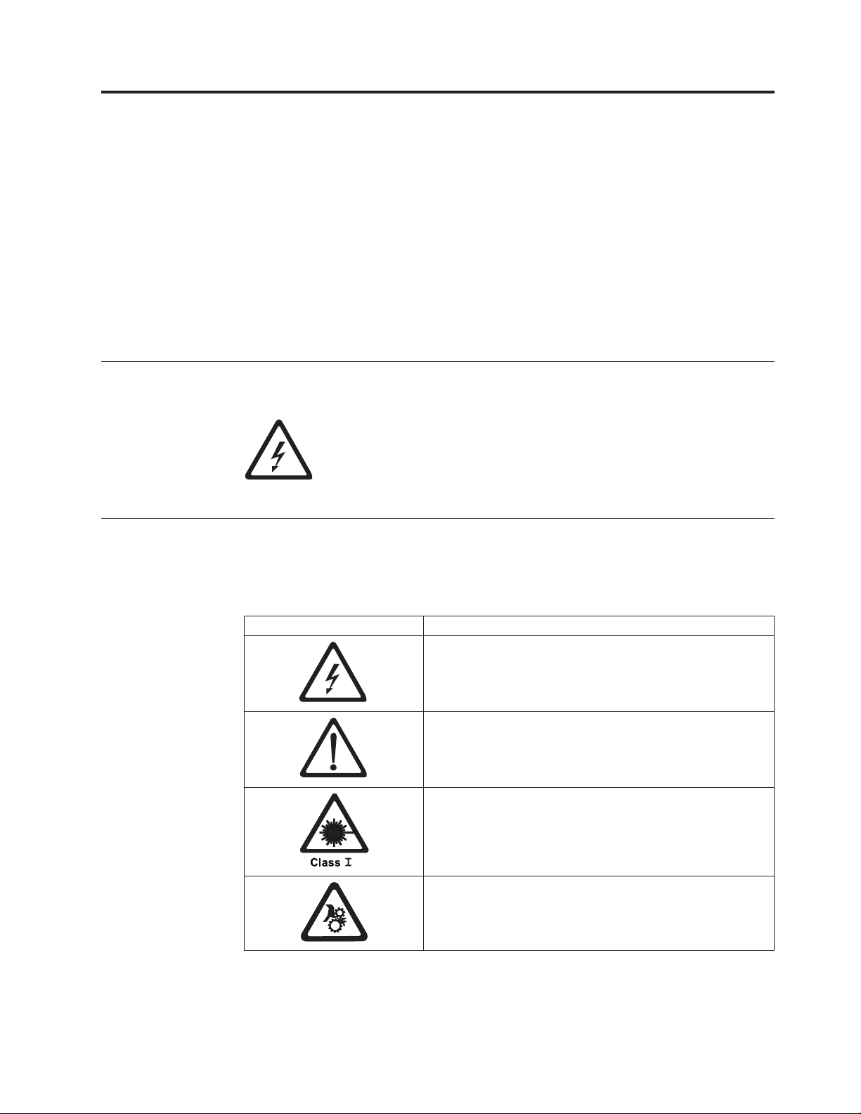
When using this product, observe the danger, caution, and attention notices
contained in this guide. Danger and caution notices are accompanied by symbols
that represent the severity of the safety condition.
á
A danger notice calls attention to a situation that is potentially lethal or
extremely hazardous to people. A lightning bolt symbol always
accompanies a danger notice to represent a dangerous electrical
condition.
A caution notice calls attention to a situation that is potentially hazardous to
people because of some existing condition. A caution notice can be accompanied
by one of several symbols:
If the symbol is... It means....
A hazardous electrical condition with less severity than
electrical danger.
A generally hazardous condition not represented by other
safety symbols.
A hazardous condition due to the use of a laser in the
product. Laser symbols are always accompanied by the
classification of the laser as defined by the U. S.
Department of Health and Human Services (for example,
Class I, Class II, and so forth).
A hazardous condition due to mechanical movement in or
around the product.
© Copyright IBM Corp. 2004, 2005 xv
Page 18
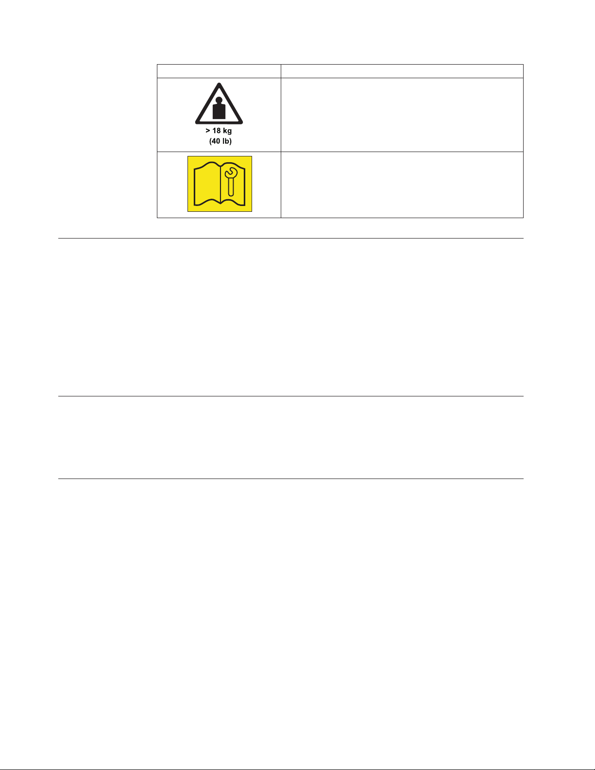
If the symbol is... It means....
Laser Safety and Compliance
Before using the Autoloader, review the following laser safety information.
Class I Laser Product
The Autoloader may contain a laser assembly that complies with the performance
standards set by the U.S. Food and Drug Administration for a Class I laser
product. Class I laser products do not emit hazardous laser radiation. The
Autoloader has the necessary protective housing and scanning safeguards to
ensure that laser radiation is inaccessible during operation or is within Class I
limits. External safety agencies have reviewed the Autoloader and have obtained
approvals to the latest standards as they apply.
A hazardous condition due to the weight of the unit.
Weight symbols are accompanied by an approximation of
the product’s weight.
Indicates access by IBM Authorized Service Personnel only.
Intended Use
Safeguards
This equipment is designed for processing magnetic tape cartridges. Any other
application is not considered the intended use. IBM shall not be held liable for
damage arising from unauthorized use of the Autoloader. The user assumes all risk
in this aspect.
To maintain safeguards, observe the following basic rules for installation, use, and
servicing of the Autoloader.
v Follow Warnings - Adhere to all warnings on the product and in the operating
instructions.
v Read Instructions - Read and follow all installation and operating instructions.
v Ventilation - Situate the Autoloader so that its location or position provides
adequate front and rear ventilation (at least two inches).
v Heat - Situate the product away from heat sources such as radiators, heat
registers, furnaces, or other heat-producing appliances.
v Power Sources - Connect the Autoloader to a power source only of the type
directed in these operating instructions or as marked on the product label.
v Power Cord Protection - Route the AC line cord so that it is not likely to be
walked on or pinched by items placed upon or against it, paying particular
attention to the cord at the wall receptacle, and the point where the cords exits
from the product.
xvi IBM 3581 Autoloader Models L28/L38/L3H and F28/F38/F3H Setup, Operator, and Service Guide
Page 19

Precautions
v Object and Liquid Entry - Take care to ensure that objects do not fall and
liquids are not spilled into the product’s enclosure through openings.
v Servicing - Do not attempt to service the product beyond that described in the
operating and installation instructions. All other servicing should be referred to
qualified service personnel.
Use these precautions when using or choosing an environment for the unit:
v Do not use oil, solvents, gasoline, paint thinners, or insecticides on the unit or
near the unit. Vapors from these types of chemicals can damage the tape media
components.
v Do not expose the unit to moisture or store the unit in temperatures higher than
60°C (140°F), or to extreme low temperatures. See “Specifications” on page 15 for
operating temperatures.
v Keep the unit away from direct strong magnetic fields, excessive dust, and
electronic or electrical equipment that generates electrical noise.
v Hold the AC power plug by the head when removing it from the AC source
outlet; pulling the cord can damage the internal wires.
v Use the unit on a firm, level surface free from vibration. Do not place any
objects on top of the unit..
Safety Inspection Procedure
Before you service the Autoloader, perform the following safety inspection
procedure:
1. Stop all activity on the SCSI bus.
2. Power off the Autoloader.
3. Unplug the Autoloader’s power cord from the electrical outlet and then from
the rear of the unit.
|
3581 Library ac Grounding Inspection
|
|
|
|
|
|
|
4. Disconnect all cables and terminators and inspect for damage.
5. Check the Autoloader’s power cord for damage, such as a pinched, cut, or
frayed cord.
6. Check the cover of the Autoloader for sharp edges, damage, or alterations that
expose its internal parts.
7. Check the cover of the Autoloader for a proper fit. It should be in place and
secure.
8. Check the product label on the bottom of the Autoloader to make sure it
matches the voltage at your outlet.
1. Power off the Autoloader.
2. Disconnect all cables.
3. See Figure 1 on page xviii which is provided for reference only. Disconnect the
power cord from its source.
4. Inspect the power cable for visible cracks, wear, or damage.
Safety and Environmental Notices xvii
Page 20
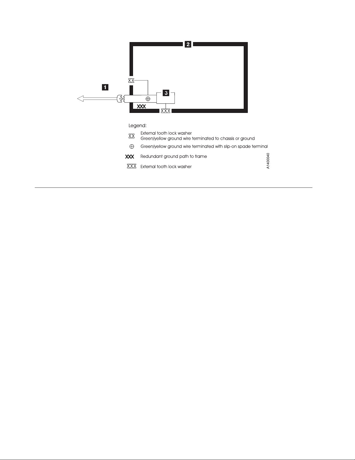
Figure 1. AC Grounding Diagram (50 Hz and 60 Hz)
|
End of Life (EOL) Plan
This box is a purchased unit. Therefore, it is the sole responsibility of the purchaser
to dispose of it in accordance with local laws and regulations at the time of
disposal.
This unit contains recyclable materials. The materials should be recycled where
facilities are available and according to local regulations. In some areas IBM may
provide a product take-back program that ensures proper handling of the product.
For more information, contact your IBM representative.
xviii IBM 3581 Autoloader Models L28/L38/L3H and F28/F38/F3H Setup, Operator, and Service Guide
Page 21

About This Guide
This Setup, Operator, and Service Guide is intended to provide information for
operators, system administrators, installer, and service personnel. The publication
is divided into the following parts:
v Part 1, “Setup Guide,” on page 1 contains product description, installation, and
configuration information.
v Part 2, “Operator Guide,” on page 43 contains menu, operation, and media
information.
v Part 3, “Service Guide,” on page 161 contains troubleshooting,
diagnostic/maintenance, serial port connection, removal/replacement, and parts
information.
v Part 4, ″The Appendix, ″ contains:
– “Element Addresses” on page 225
– “TapeAlert Flags” on page 227
– “Messages” on page 233
– “Sense Data” on page 241
– “Autoloader Configuration Form” on page 251
– “Rack Mount Template” on page 253
– “Information for IBM Service Personnel” on page 255
Store
information, refer to the section that follows.
Related Publications
Refer to the following publications for additional information about the
Autoloader. To ensure that you have the latest versions of the publications, visit
the web at http://www.ibm.com/storage/support/lto.
|
3581 Autoloader Publications
The following publications can be accessed at
http://ehone.ibm.com/public/applications/publications/cgibin/pbi.cgi.
v IBM TotalStorage Ultrium Tape Autoloader 3581 Models L28/L38/L3H and
this guide with your server’s (host’s) manuals. For additional reference
F28/F38/F3H Quick Reference, GX35-5071, provides quick start information for the
Autoloader.
IBM TotalStorage Ultrium Tape Autoloader 3581 Models L28/L38/L3H and
F28/F38/F3H SCSI Reference, GA32–0471, provides the supported SCSI commands
and protocol that govern the behavior of the SCSI interface for the 3581 Tape
Autoloader.
IBM TotalStorage LTO Ultrium Tape Drive SCSI Reference, GA32–0450, provides
information on the use and programming of all models of the LTO Ultrium Tape
Drive.
|
|
|
© Copyright IBM Corp. 2004, 2005 xix
Redbooks
v The IBM LTO Ultrium Tape Libraries Guide provides information on all LTO tape
drive products.
Page 22

|
|
|
|
|
|
Device Driver Publications
Safety Publications
v Using IBM LTO Ultrium with Open Systems, SG-6502, provides information on all
LTO tape drive products.
v Implementing IBM LTO in Linux and Windows, SG-6268, provides information on
all LTO tape drive products.
v IBM Ultrium Device Drivers Installation and User’s Guide, GA32-0430, provides
instructions for attaching IBM-supported hardware to open-systems operating
systems. It indicates what devices and levels of operating systems are supported,
gives the requirements for adapter cards, and tells how to configure servers to
use the device driver with the Ultrium family of devices. To order by using File
Transfer Protocol (FTP), visit ftp://ftp.software.ibm.com/storage/devdrvr.
v IBM TotalStorage Ultrium Device Drivers Programming Reference, GC35-0483,
supplies information to application owners who want to integrate their
open-systems applications with IBM-supported Ultrium hardware. The reference
contains information about the application programming interfaces (APIs) for
each of the various supported operating-system environments. To order by using
File Transfer Protocol (FTP), visit ftp://ftp.software.ibm.com/storage/devdrvr.
v IBM Externally Attached Devices Safety Information, SA26-2004, provides
translations of safety notices.
|
Online Support
|
|
|
|
|
|
|
|
|
|
|
|
SCSI Publications
Autoloader Firmware
IBM Online Support
IBM Publications Center
IBM Redbooks
v SCSI-3 Stream Commands (SSC), published by the American National Standards
Institute and available on the web at http://www.t10.org.
v SCSI Primary Commands-2 (SPC-2), published by the American National
Standards Institute and available on the web at http://www.t10.org.
v http://www.ibm.com/storage/support/lto/
v ftp://index.storsys.ibm.com/358x
v http://www.ibm.com/storage/support/lto/
v http://www.ibm.com/support/mySupport
v http://ehone.ibm.com/public/applications/publications/cgibin/pbi.cgi
v http://www.ibm.com/storage/support/lto/
v http://w3.itso.ibm.com/
|
|
|
Device Drivers
v ftp://ftp.software.ibm.com/storage/devdrvr
v ftp://index.storsys.ibm.com/358x
xx IBM 3581 Autoloader Models L28/L38/L3H and F28/F38/F3H Setup, Operator, and Service Guide
Page 23

|
|
Media and Supplies
http://www.ibm.com/storage/media/
About This Guide xxi
Page 24

xxii IBM 3581 Autoloader Models L28/L38/L3H and F28/F38/F3H Setup, Operator, and Service Guide
Page 25

Part 1. Setup Guide
Product Description . . . . . . . . . . .3
Product Features . . . . . . . . . . . . .4
Standard Features . . . . . . . . . . .4
| |
Optional Features . . . . . . . . . . . .6
| |
Component Descriptions . . . . . . . . . .7
Front Panel Components . . . . . . . . .7
Interior Components . . . . . . . . . . .8
| |
Rear Panel Components . . . . . . . . .10
| |
Media . . . . . . . . . . . . . . . .11
Tape Drive Performance . . . . . . . . . .12
Interfaces . . . . . . . . . . . . . . .12
||
SCSI Differential (HVD) . . . . . . . . .12
||
SCSI Differential (LVD) . . . . . . . . .13
||
Fibre Channel Supported Topologies . . . . .13
||
Server (Host) Attachment . . . . . . . . . .14
Supported Servers (Hosts) and Operating
Systems . . . . . . . . . . . . . .14
Supported Device Drivers . . . . . . . .15
TapeAlert Support . . . . . . . . . . . .15
Specifications . . . . . . . . . . . . . .15
Installation . . . . . . . . . . . . . .17
Step 1. Unpack the Autoloader . . . . . . . .18
Step 2. Verify the Shipment Inventory . . . . .19
Step 3. Inspect the Power Cord and Outlet . . . .21
Step 4. Install the Optional Remote Management
Unit (RMU) . . . . . . . . . . . . . .22
Tools Required . . . . . . . . . . . .22
Installing the RMU . . . . . . . . . . .22
Step 5. Install the Optional HVD Converter (L28
Models Only) . . . . . . . . . . . . . .23
Tools Required . . . . . . . . . . . .23
Installing the HVD Converter . . . . . . .23
Step 6. Install the Optional Bar Code Reader (BCR) 25
Tools Required . . . . . . . . . . . .25
Installing the BCR . . . . . . . . . . .25
Step 7. Install the Autoloader as a Desktop Unit . .26
Step 8. Install the Autoloader in a Rack . . . . .27
Rack Safety . . . . . . . . . . . . .27
||
||
||
Rack Installation . . . . . . . . . . .27
Rack Relocation (19″ Rack) . . . . . . .28
Tools Required . . . . . . . . . . . .28
Verify the Rack Mount Kit . . . . . . . .28
Check the Installation Environment . . . . .30
Prepare the Autoloader for Installation . . . .31
Install the Support Rails in the Rack . . . . .31
Install the Rack Front-Mount Brackets on the
|
Autoloader . . . . . . . . . . . . .33
||
Secure the Autoloader to the Rack . . . . . .34
Step 9. Connect Power . . . . . . . . . . .36
Desktop Installation . . . . . . . . . .36
||
Rack Installation . . . . . . . . . . . .36
||
Running a Drive Recalibration Test . . . . .37
||
LIBRARY VERIFY Test . . . . . . . . . .37
Step 10. Connect the Autoloader to Your Server
(Host) . . . . . . . . . . . . . . . .38
RMU Cabling . . . . . . . . . . . . .38
SCSI Interface . . . . . . . . . . . .38
Attaching to a SCSI-LVD System . . . . .38
Attaching to a SCSI-HVD System . . . . .39
Fibre Channel Interface . . . . . . . . .39
Step 11. Power on the Autoloader . . . . . . .41
Configuring Your Autoloader . . . . . . . .41
Saving / Restoring VPD on the RMU . . . . .41
© Copyright IBM Corp. 2004, 2005 1
Page 26

2 IBM 3581 Autoloader Models L28/L38/L3H and F28/F38/F3H Setup, Operator, and Service Guide
Page 27
Product Description
|
|
|
|
|
|
|
|
|
|
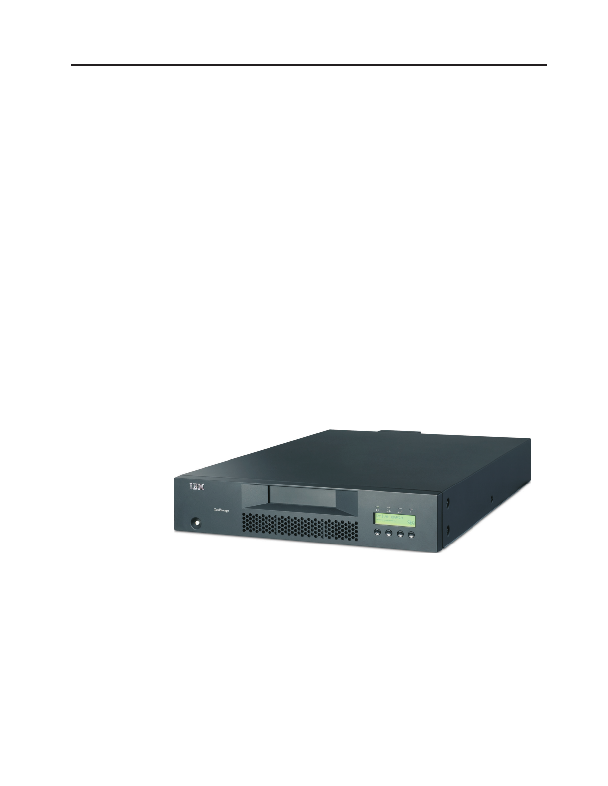
The IBM TotalStorage
F28/F38/F3H offer high capacity, performance, and technology designed for the
mid-range open systems environment. These models incorporate a single Linear
Tape Open (LTO) IBM TotalStorage Ultrium 2 (Models L28/F28) or Ultrium 3
(Models L38/F38/L3H/F3H) Tape Drive. The IBM TotalStorage Ultrium 3 Tape
Drive more than doubles tape drive performance over the previous generation
Ultrium 2 Tape Drive, with up to 80 MB per second native data transfer rate. In
addition, with the use of the new IBM TotalStorage Ultrium 400 GB Data
Cartridge, the Ultrium 3 Tape Drive has the capability of writing twice as much
data, up to 400 GB native capacity (800 GB with 2:1 compression).
®
Ultrium Tape Autoloader 3581 Models L28/L38/L3H and
|
|
|
|
|
|
|
|
|
|
|
|
The Model L28/L38/L3H comes with an LVD Ultra160 SCSI attachment, while the
Model F28/F38/F3H comes with a Native Switched Fabric Fibre Channel
attachment, for connection to a wide spectrum of open systems servers. Both
models connect to a wide spectrum of open systems servers. Note that the Ultrium
3 Tape Drive does not support HVD technology.
The 3581 Tape Autoloader is a desktop or rack-mountable unit (requiring two rack
units) that operates in automatic, sequential, or random mode and comes equipped
with a robotic interface that moves tape cartridges to and from the drive and
cartridge carousel. With an eight tape cartridge capacity, it provides a media
capacity of up to 3.2 TB (6.4 TB with 2:1 compression) data storage per unit.
Optional features include an HVD Converter, a Remote Management Unit (RMU),
and a Bar Code Reader (BCR).
Figure 2. IBM TotalStorage Ultrium Tape Autoloader 3581 Models L28/L38/L3H and
F28/F38/F3H
|
The Autoloader’s Ultrium 2 and Ultrium 3 Tape Drive offer:
v Digital speed matching
|
The Ultrium 2 and Ultrium 3 Tape Drive will perform dynamic speed
matching to adjust the drive’s native data rate as closely as possible to the
net host data rate (after data compressibility has been factored out). This
offers the dual benefit of reducing the number of backhitch repositions and
improving throughput performance.
Power management
v
© Copyright IBM Corp. 2004, 2005 3
a67s0243
Page 28

The power management function controls the drive’s electronics to be either
completely turned off or to be in a low-power mode. These power modes
occur only when the circuit functions are not needed for drive operation.
v Channel calibration
The channel calibration feature allows for customization of each read/write
data channel for optimum performance. The customization enables
compensation for variations in the recording channel transfer function, media
characteristics, and read/write head characteristics.
v Separate writing of multiple filemarks
Separate writing of multiple filemarks causes any write command of two or
more filemarks to cause a separate data set to be written containing all
filemarks after the first. This feature has two advantages:
- First, it can improve performance if a subsequent append overwrites
somewhere after the first filemark.
- Second, write of multiple filemarks typically indicates a point where an
append operation might occur after the first of these filemarks.
change prevents having to rewrite datasets containing customer data
This
and the first filemark in cases when (where) such an append occurs.
Large internal buffer
v
|
|
|
The Ultrium 2 Tape Drive and has a 64 MB internal data buffer. The Ultrium
3 Tape Drive has a 128 MB internal buffer .
Fast cartridge fill times (for Ultrium 3, Ultrium 2 and Ultrium 1 data cartridges)
v
v Fast data access, rewind, and load times
|
Table 1. Data access, rewind, and load times
|
Action Autoloader Ultrium 2 Tape Drive Ultrium 3 Tape Drive
||||
Cartridge Load Time 32 seconds 15 seconds 10 seconds
||||
Maximum Rewind Time N/A 80 seconds 88 seconds
||||
Average File Access Time N/A 49 seconds 49 seconds
||||
|
Product Features
This section describes the standard and optional features of the Autoloader.
Standard Features
The Autoloader includes the following standard features:
v Operator Control Panel (OCP)
The OCP provides an easy-to-read display and a four button keypad
allowing the user to monitor and control the operations of the Autoloader.
The OCP’s display provides access to library status, commands, setup, and
tools. See “Front Panel Components” on page 7 and “Operator Control Panel
(OCP)” on page 46 for additional information.
v Robotic system
The Autoloader’s robotic system includes an I/O Door, a cartridge carousel
with cartridge slots, and a cartridge loader. The I/O Door allows importing
or exporting a single cartridge to or from the Autoloader. The cartridge
|
carousel encircles the Ultrium 2 and Ultrium 3 Tape Drive and positions the
specified cartridge slot in front of the tape drive. A robotic cartridge loader
moves the cartridges between the cartridge slots and the tape drive.
4 IBM 3581 Autoloader Models L28/L38/L3H and F28/F38/F3H Setup, Operator, and Service Guide
Page 29

v Eight-cartridge capacity
|
Up to eight Ultrium 3, Ultrium 2 or Ultrium 1 tape cartridges can be stored
in cartridge slots mounted on the carousel.
Cartridge inventory
v
Each time the Autoloader is powered on, an inventory of all cartridge slots is
performed.
Setup Guide: Product Description 5
Page 30

v Built-in diagnostics
The Autoloader includes firmware that performs diagnostic tests and reports
drive operating status. An error and event log is available through the OCP
or optional RMU.
|
|
|
Ultrium 2 or Ultrium 3 Tape Drive
v
The Autoloader is available with an LVD SCSI (Model L28/L38/L3H) or a
Fibre Channel (Model F28/F38/F3H) Ultrium 2 or Ultrium 3 Tape Drive.
Optional Features
The Autoloader has the following optional features:
v Bar Code Reader (BCR)
The BCR reads bar code labels and sends the label IDs to the server (host)
and to the Remote Management Unit (RMU), if installed.
Remote Management Unit (RMU)
v
The RMU provides remote access to the Autoloader over a network via a
web browser and makes functions accessible without the need for a
dedicated server or separate software.
HVD Converter
v
The HVD Converter is a SCSI HVD to LVD converter/expander. It converts
the Autoloader’s low voltage differential (LVD) to wide high voltage
differential (HVD). This allows LVD-peripherals to be used on an HVD bus.
The converter can also be used to reshape poor quality LVD signals, and
allow additional cable length.
Rack Mount Kit
v
The Rack Mount Kit supplies the necessary mounting hardware to install the
Autoloader in a 19-inch rack.
6 IBM 3581 Autoloader Models L28/L38/L3H and F28/F38/F3H Setup, Operator, and Service Guide
Page 31

Component Descriptions
This section contains descriptions of the following:
v “Front Panel Components”
v “Interior Components” on page 8
v “Rear Panel Components” on page 10
Front Panel Components
Figure 3 shows the Autoloader’s front panel components.
Figure 3. Front panel components
™
1POWER
For powering the Autoloader on and off.
2I/O Door
Allows the user to insert or remove cartridges from the Autoloader.
3Operator Control Panel (OCP)
Allows the operator to control the Autoloader without a Remote
button
Management Unit (RMU) and contains the following:
- Status LEDs (4)
- Liquid crystal display (OCP display)
- Keypad with four buttons (Cancel, Previous, Next, Enter)
4 Serial Number
A label with machine type, model, and serial number.
Setup Guide: Product Description 7
Page 32

Interior Components
Figure 4 shows the Autoloader’s interior components and one cartridge slot.
|
|
|
|
|
á
Attention: Only IBM Authorized Service Personnel should remove the
Autoloader’s cover.
||
|
4
3
2
1
a67s0179
Figure 4. Interior components with one cartridge slot
1Cartridge slot
Each cartridge is installed in a cartridge slot to ensure the cartridge is
properly aligned for insertion into the tape drive.
2Cartridge loader
The cartridge loader moves cartridges between the cartridge slots and the
tape drive. When a cartridge slot is positioned in front of the drive, the
loader grips the sides of the cartridge and slides it forward or backward
between the slot and drive. The loader then releases the cartridge and
pushes it firmly into the drive or slot.
3Ultrium 2 or Ultrium 3 Tape Drive (LVD or Fibre Channel)
|
|
|
|
|
|
|
|
|
|
Generation 2 models of the Autoloader contain one LVD (Model L28) or
Fibre Channel (Model F28) Ultrium 2 Tape Drive. The drive can sustain a
maximum data transfer rate of 107 MB per second (compressed) and can
store up to 400
®
GB of compressed information on a single data cartridge
(assuming an average compression ratio of 2:1.)
Generation 3 models of the Autoloader contain one LVD (Model L38/L3H)
or Fibre Channel (Model F38/F3H) Ultrium 3 Tape Drive. The drive can
sustain a maximum data transfer rate of 160 MB per second and can store
up to 800 GB of compressed information on a single data cartridge
(assuming an average compression ratio of 2:1).
8 IBM 3581 Autoloader Models L28/L38/L3H and F28/F38/F3H Setup, Operator, and Service Guide
Page 33

4Carousel
The carousel stores up to eight Ultrium 3, Ultrium 2 or Ultrium 1 data
cartridges. The carousel consists of a drive chain, guides, and gears that
move the cartridges into position in front of the drive.
Setup Guide: Product Description 9
Page 34

Rear Panel Components
All rear panels regardless of configuration contain the following standard elements:
v 1Power cord receptacle
Provides AC power and chassis grounding to the Autoloader.
|
|
|
2 Power Ratings / Warning Label
v
A label showing power ratings and warning the customer not to remove the
cover of the Autoloader.
|
|
Power Ratings: 100 - 240V~
1.3 - 07A 50 -60Hz
!
a67s0271
|
|
|
|
|
|
|
|
|
|
Figure 5. Rear panel label showing power ratings and warning customers not to remove the
Autoloader cover
v 3Fan
Provides cooling for the Autoloader.
4Serial Port
v
Allows serial communication between the Autoloader and a server (host).
6 shows the rear panel components of the Autoloader with an LVD SCSI
Figure
(Model L28/L38/L3H) drive.
v 5SCSI Receptacles
The Autoloader has two HD68 SCSI receptacles for connecting the
Autoloader to a single LVD SCSI bus to accommodate one of the following:
- A SCSI cable connecting the Autoloader to a server (host).
- A wide external terminator or a cable to another SCSI device.
|
|
|
|
|
5
4
3
2
Figure 6. Rear panel with standard elements and SCSI connectors with an LVD SCSI (Model
L28lL38/L3H) drive
Figure 7 on page 11 shows the rear panel components of the Autoloader with an
LVD SCSI drive (Model L28/L38/L3H) and HVD Converter.
v 1Optional HVD Converter
10 IBM 3581 Autoloader Models L28/L38/L3H and F28/F38/F3H Setup, Operator, and Service Guide
1
a67s0202
Page 35

Used to convert an Autoloader with an LVD SCSI drive to communicate with
an HVD system.
Figure 7. Rear panel components with an LVD SCSI drive (Model L28/L38/L3H) and HVD
Converter
1
a67s0197
|
|
|
|
|
|
Media
|
|
|
Figure 8 shows the rear panel components of the Autoloader with a Fibre Channel
(Model F28/F38/F3H) drive.
v 1Fibre Channel Receptacle
The receptacle for the Fibre Channel interface cable that connects the
Autoloader with the server (host).
1
Figure 8. Rear panel with a Fibre Channel (Model F28/F38/F3H) drive connection
The Autoloader uses the following cartridge types:
v
v IBM TotalStorage LTO Ultrium 400 GB Data Cartridge (Ultrium 3)
v IBM TotalStorage LTO Ultrium 200 GB Data Cartridge (Ultrium 2)
v IBM LTO Ultrium Data Cartridge (Ultrium 1 with 100 GB capacity)
v IBM TotalStorage LTO Ultrium Cleaning Cartridge
v LTO Ultrium Cleaning Cartridge (universal cleaning cartridge compatible with
Ultrium 3, Ultrium 2 and Ultrium 1 drives)
a67s0204
additional information, refer to “Media” on page 143.
For
Setup Guide: Product Description 11
Page 36

Tape Drive Performance
|
Table 2. Performance characteristics of the Ultrium 2 and Ultrium 3 Tape Drive
|
|
|
||
||||
|
|||
|
|||
|
|||||
|||
|||
|
|
|
|
||
|
|
|
|
|||
|||
||||
|
|
|
|
|
|
|
|
Performance Characteristic
Native sustained data rate N/A
Compressed data rate (at 2:1
compression)
Maximum sustained data rate (at
maximum compression)
Burst data rate 160 MB/s (LVD)
Nominal load-to-ready time 15 seconds 15 seconds
Nominal unload time 15 seconds 15 seconds
Average search time to first byte of
data
Note: Although the Autoloader provides the capability for high tape performance, the actual throughput is a
function of many components, such as system processor, disk data rate, data block size, data compressibility, I/O
attachments, and the system or application software used. For example, the HVD Ultra SCSI converter interface has
a maximum data transfer rate of 40 MB/second, so Ultrium Tape Drives on that SCSI interface will have a lower
data transfer rate. The compression technology used in the tape drive can typically double the amount of data that
can be stored on the media; however, the actual degree of compression achieved is highly sensitive to the
characteristics of the data being compressed.
Ultrium 2 Tape Drive Ultrium 3 Tape Drive
(with Ultrium 3 media)
35 MB/s
(with Ultrium 2 media)
20 MB/s
(with
Ultrium 1 media)
70 MB/s
(with Ultrium 2 media)
40 MB/s
(with Ultrium 1 media)
107 MB/s (LVD)
37 MB/s (HVD)
110 MB/s (Fibre Channel)
40 MB/s (HVD)
200 MB/s (Fibre Channel)
49 seconds 47 seconds
Tape Drive
(with
200 MB/s (Fibre Channel-2Gbits)
80 MB/s
(with Ultrium 3 media)
35 MB/s
(with Ultrium 2 media)
20 MBs
Ultrium 1 media - read only)
135 MB/sec (SCSI)
150 MB/sec (FC)
135 MB/s (LVD)
150 MB/s (Fibre Channel)
160 MB/s (LVD)
|
Interfaces
|
|
|
SCSI Differential (HVD)
|
|
|
|
|
|
|
|
|
|
|
The Autoloader is available with a choice of interfaces, either SCSI HVD (with the
optional HVD Converter or) LVD, or Fibre Channel.
The SCSI differential HVD converter is only available on Ultrium 2 tape drives.
HVD (often referred to as just ″differential″) uses differential signaling. The idea
behind differential signals is that each bus signal is carried on a pair of wires. The
first wire of the pair carries the same type of signal as single-ended SCSI.
However, the second wire of the pair carries its logical inversion. The receiver of
the signals takes the difference of the pair (hence the name), which makes it less
susceptible to noise and capable of supporting greater cable lengths. HVD and
single-ended SCSI are completely incompatible with each other.
In general, IBM HVD tape devices support an overall bus length of 25 meters,
using point-to-point or multi-drop interconnection (daisy-chaining). For each
daisy-chained device, the maximum cable length must be reduced by 0.5 meters.
12 IBM 3581 Autoloader Models L28/L38/L3H and F28/F38/F3H Setup, Operator, and Service Guide
Page 37

|
|
|
|
|
|
|
|
|
|
|
|
|||||
|||||
|||||
|||||
||||||
||||||
||||||
|
|
|
|
|
|
SCSI Differential (LVD)
LVD uses less power than the HVD differential interface, and allows the higher
speeds of Ultra-2 SCSI. LVD requires 3.3 V dc instead of 5 V dc for HVD.
IBM LVD tape devices support a bus length of 25 meters point-to-point, and 12
meters using multi-drop interconnection (daisy-chaining). For each daisy-chained
device, the maximum cable length must be reduced by 0.5 meters.
The terms fast, wide, and ultra indicate characteristics that are separate from those
implied by differential, single-ended, and high or low voltage. Table 3 shows the
SCSI terms used to describe different host and device adapters and what they
imply in terms of bus width and speed.
Table 3. SCSI terms and characteristics
SCSI Term Bus Width (bits) Speed (MB/s) Max. Length Max. Devices
SCSI 8 5 6 m 7
Fast SCSI 8 10 3 m 7
Fast Wide SCSI 16 20 3 m 15
Ultra (Wide)
SCSI HVD
Ultra (Wide)
SCSI 2 LVD
Ultra 160 SCSI
LVD
Note: A faster bus does not imply that an attached device will support that data rate, but
that multiple devices can operate on the bus at that maximum speed. For a detailed table
of SCSI terms and related specifications, refer to the SCSI Trade Association Web site at
http://www.scsita.org/terms/scsiterms.html. To ensure best performance, if possible, avoid
daisy-chaining.
16 40 25 m 15
16 80 25 m / 12 m 15
16 160 25 m / 12 m 15
|
|
|
|
|
|
|
|
|
|
|
|
|
|
|
|
|
Fibre Channel Supported Topologies
Fibre Channel allows for an active intelligent interconnection scheme, called a
Fabric, to connect devices. Everything between the ports on Fibre Channel is called
the Fabric. The Fabric is most often a switch or series of switches that takes the
responsibility for routing. Fibre channel supports three basic topologies:
v Arbitrated loop (supported by the Autoloader)
v Switched Fabric (supported by the Autoloader)
v Point-to-point (unsupported by the Autoloader)
actual topology is transparent to each individual attached device. All
The
point-to-point and arbitrated loop topologies require that all nodes use the same
data rate at all times. In the switched topology, different speed devices can be
supported.
The Switched Fabric topology is similar to the star network layout commonly
implemented on networks that use twisted pair cabling. A central device, in this
case a fibre channel switch, provides a central connectivity point for all of the
devices in the fabric. This allows each node to access all other nodes that are
connected to the fabric.
Setup Guide: Product Description 13
Page 38

|
|
|
|
|
|
|
The Autoloader allows the selection of the following Fibre channel port behaviors:
v LN Port: (default setting) an automatic configuration that tries arbitrated loop
first, then switched fabric.
v NL Port: an automatic configuration that tries switched fabric first, then
arbitrated loop.
v L Port: arbitrated loop.
v N Port: point to point protocol in a switched fabric topology.
Server (Host) Attachment
|
The Autoloader supports LVD Ultra160, HVD Ultra SCSI (with the optional HVD
Converter) or Fibre Channel interfaces. The Autoloader features two HD68
receptacles or one LC Fibre Channel receptacle. For instructions on attaching your
Autoloader to a server (host), see “Step 4. Configure the Autoloader to the Server
(Host)” on page 110.
Supported Servers (Hosts) and Operating Systems
The Autoloader is supported by a wide variety of servers (hosts) and operating
systems, as well as adapters. The following operating systems are supported by the
Autoloader:
v AS/400
v HP-UX
|
|
|
|
v IBM Eserver i5 and iSeries
v IBM Eserver p5 and pSeries
v IBM Eserver xSeries
v Linux
v Microsoft
v Microsoft Windows 2003
v Microsoft Windows NT
v Netfinity
v RS/6000
v RS/6000 SP
v Sun
v zSeries
®
™
®
®
®
Windows
®
®
™
®
Linux (Model F28/F38/F3H only)
®
2000
®
(Ultrium 2 only)
determine the latest supported attachments and host software versions and
To
releases, visit the web at http://www.ibm.com/storage/support/lto. Select ″LTO
Support″, then the ″Interoperability Matrix and Software ISVs″, and view the
″Supported Servers and Operating Systems″.
Note:
1. IBM does not provide backup application software with the Autoloader.
To order software, contact your IBM marketing representative, IBM
Business Partner, or an independent software provider.
2. If you attach your library to a non-IBM platform with non-IBM software,
IBM recommends that you contact your software vendor to obtain a
matrix of compatible hardware, software, firmware revisions, and
adapter cards.
14 IBM 3581 Autoloader Models L28/L38/L3H and F28/F38/F3H Setup, Operator, and Service Guide
Page 39

Supported Device Drivers
Device drivers for each supported operating system listed above are available from
IBM for downloading. For device driver downloading and installation instructions,
see “Step 3. Install Device Drivers” on page 110.
TapeAlert Support
The Autoloader is compatible with TapeAlert technology, which provides error and
diagnostic information to the server (host). For more information, see “TapeAlert
Flags” on page 227.
Specifications
Specifications for the Autoloader are listed in the following tables below:
v Table 4 for Physical Specifications
v Table 5 for Power Specifications
v Table 6 for Acoustic Specifications
v Table 7 on page 16 for Environmental Specifications
Specifications
for tape cartridges are given in “Environmental and Shipping
Specifications for Tape Cartridges” on page 151.
|
|
Table 4. Physical Specifications for the Autoloader
Physical Specifications
Desktop Version Rack Mount Version
Width 421 mm/16.6 in. 483 mm/19 in.
Depth 665 mm/26.2 in. 660 mm/26 in.
Height 86 mm/3.4 in. 89 mm/3.5 in.
Weight Approx. 12.5 kg/27.56 lbs.(max.) without Rack Mount Kit
Table 5. Power Specifications for the Autoloader
Power Specifications
AC line voltage 100 to 240 Vac
Line frequency 50 to 60 Hz auto-ranging
Line current at 100 Va c 1.3 A
Line current at 240 Va c 0.7 A
Maximum heat output 100 watts (86 KCAL/hr.)
Table 6. Acoustic Specifications for the Autoloader
Acoustic Specifications
Maximum noise level Idling Operating
60 db (6.3 bels) 62 db (6.5 bels)
Setup Guide: Product Description 15
Page 40

Table 7. Environmental Specifications for the Autoloader
Environmental Specifications
Environmental
Factor
Power On Power Off
1
Storage
2
Shipment
2
Temperature +10°C to +35°C +10°C to 43°C 1°C to 60°C -40°C to +60°C
Temperature
Variation
Relative humidity
(noncondensing)
10°C/Hr max 10°C/Hr max 10°C/Hr max 10°C/Hr max
15% to 85% 10% to 90% 10% to 90% 10% to 90%
Wet bulb (max.) 26°C 27°C 29°C 29°C
|
Altitude (meters) 0 to 2500 0 to 2500 0 to 2500 0 to 12192
Note: The operating environment of the Autoloader must not conflict with the media
storage requirements (see “Environmental and Shipping Specifications for Tape Cartridges”
on page 151). While the Autoloader may be capable of operating at elevated temperatures
for an extended period of time, the temperature could shorten the useful life of media that
is stored in the Autoloader. If media is stored in the Autoloader for more than 10 hours,
the storage temperature requirements for media should be met. It should be assumed that
media stored in the Autoloader will be 2 degrees above ambient room temperature when
the Autoloader is powered on.
1. Values indicated are valid for the unpacked unit with no data cartridge. If there is a
cartridge with the unit either inside or out, then the ″Power On″ specification must
apply to the ″Power Off″ situation.
2. Values indicated are valid for the packaged unit. The storage period should not exceed
three (3) years. The limits are for the ambient temperature within 1 meter from the
packaged unit.
16 IBM 3581 Autoloader Models L28/L38/L3H and F28/F38/F3H Setup, Operator, and Service Guide
Page 41

Installation
Installation and configuration of the Autoloader can be accomplished by following
the steps outlined in this chapter. If some options were not purchased with the
Autoloader, skip the steps related to installing those options not purchased and
proceed to the next step to continue the installation.
Attention
1. The Autoloader is a customer setup unit. It is the customer’s responsibility
to install this product.
2. The Autoloader Models L28/L38/L3H and F28/F38/F3H offer a 3-year
warranty. These models are designed as Customer Replaceable Units
(CRU). The warranty is a parts-only warranty. For details about the
Customer Replaceable Unit process and customer responsibilities, see
“Statement of Limited Warranty” on page 298.
To install the Autoloader, complete the following steps. For more information, refer
to the instructions for each step in this chapter.
__ v “Step 1. Unpack the Autoloader” on page 18
__ v “Step 2. Verify the Shipment Inventory” on page 19
__ v “Step 3. Inspect the Power Cord and Outlet” on page 21
__ v “Step 4. Install the Optional Remote Management Unit (RMU)” on page 22
__ v “Step 5. Install the Optional HVD Converter (L28 Models Only)” on page 23
__ v “Step 6. Install the Optional Bar Code Reader (BCR)” on page 25
__ v “Step 7. Install the Autoloader as a Desktop Unit” on page 26
__ v “Step 8. Install the Autoloader in a Rack” on page 27
__ v “Step 9. Connect Power” on page 36
__ v “Step 10. Connect the Autoloader to Your Server (Host)” on page 38
__ v “Step 11. Power on the Autoloader” on page 41
detailed instructions on performing each step, refer to the sections that follow.
For
© Copyright IBM Corp. 2004, 2005 17
Page 42

Step 1. Unpack the Autoloader
__ 1. If the operating environment differs from the storage environment by 15°C
(30°F) or more, let the Autoloader acclimate to the surrounding environment
for at least 12 hours before opening the shipping carton (see Table 7 on page
16).
__ 2. Unpack the Autoloader.
__ a. Remove the accessories package, any options packages, and other
contents from the outer box.
__ b. Open the inner box and lift the Autoloader and padding out of the
box.
__ c. Place the Autoloader on a sturdy work surface with the top of the
unit facing up.
__ d. Carefully remove the shipping padding from the left and right sides
of the Autoloader
__ e. Remove the Autoloader from the plastic bag.
__ f. Save the packing materials and boxes for storing or shipping the
Autoloader in the future.
3. Inspect the Autoloader for shipping damage. If there is damage, do not
__
install the Autoloader. Report the damage immediately by contacting your
place of purchase.
__ 4. Copy the “Autoloader Configuration Form” on page 251. This form is to be
filled out with your Autoloader’s vital product data and stored in a secure
location for future use. Should you need to contact IBM Technical Support,
you will be asked for these numbers.
Remember to update the Autoloader Configuration Form when
Note:
changes are made to the configuration of the unit or firmware is
upgraded.
__ 5. In the lower right corner of the front of the Autoloader, locate the label that
gives the machine type (3581), model number (for example, L28) and serial
number (S/N) of the Autoloader (see Figure 3 on page 7). Enter these
numbers on your Configuration Form.
__ 6. On the underside of your Autoloader, locate the Agency Label. This label
contains information regarding the various safety certifications associated
with the Autoloader. Also on this label is a part number and revision
number. Enter these numbers on your Configuration Form.
18 IBM 3581 Autoloader Models L28/L38/L3H and F28/F38/F3H Setup, Operator, and Service Guide
Page 43

Step 2. Verify the Shipment Inventory
Table 8. Shipment inventory checklist
One Power cord (for the appropriate cord for your country or region, see “Power Cords” on page 218)
One IBM TotalStorage LTO Ultrium 200 GB Data Cartridge (to be used for diagnostic purposes)
|
One IBM TotalStorage Ultrium Cleaning Cartridge (universal)
One Device Driver Installation Kit that includes:
v CD that contains Open System device drivers, the IBM Ultrium Device Drivers Installation and User’s Guide, and the
IBM Ultrium Device Drivers Programming Reference
v Published copy of the IBM Ultrium Device Drivers Installation and User’s Guide
One SCSI Ultra 2 LVD/SE terminator (with Model L28/L38/L3H)
SCSI ULTRA 2 LVD/SE
One fiber cable (1with Model F28/F38/F3H) or one SCSI cable (2with Model L28/L38/L3H)
|
a1400419
1
2
One SCSI LVD wrap tool (1with Model L28/L38/L3H) or one Fiber wrap tool (2with Model F28/F38/F3H)
|
a67s0194
1
SCSI LVD WRAP TOOL
2
a67s0195
Setup Guide: Installation 19
Page 44

Table 8. Shipment inventory checklist (continued)
One serial cable
a67s0196
Autoloader documentation CD-ROM containing:
v This document, the IBM TotalStorage Ultrium Tape Autoloader 3581 Models L28/L38/L3H and F28/F38/F3H Setup,
Operator, and Service Guide which includes the Limited Statement of Warranty
v The IBM TotalStorage Ultrium Tape Autoloader Models L28/L38/L3H and F28/F38/F3H Quick Reference
v The IBM Externally Attached Devices Safety Information manual, SA26-2004
The Quality Hotline card
PCC cable for Autoloader installed in a rack (cable included in ship group when Rack Mount Kit is ordered)
|
a67s0273
|
If your order has missing parts or was damaged in shipment, please contact your
place of purchase or refer to the Quality Hotline card included with your
shipment.
20 IBM 3581 Autoloader Models L28/L38/L3H and F28/F38/F3H Setup, Operator, and Service Guide
Page 45

Step 3. Inspect the Power Cord and Outlet
__ 1. Inspect the power cord plug to ensure that it matches the power receptacle.
If it does not match, refer to “Power Cords” on page 218 then contact your
place of purchase.
__ 2. Ensure that the electrical outlets used are properly grounded and that the
circuit breaker is turned on.
Setup Guide: Installation 21
Page 46

Step 4. Install the Optional Remote Management Unit (RMU)
The Remote Management Unit (RMU) provides remote access to the Autoloader
over a network. The Autoloader can be attached to the network through a 10/100
Ethernet port located on the RMU. Any server (host) can access the Autoloader if it
has a web browser installed and the IP Address of the Autoloader is known.
Tools Required
v T10 Torx wrench or small flat-blade screwdriver
|
|
|
|
|
|
á
CAUTION:
ESD Sensitive Component. Please touch the unit cover or rear panel
before installing the RMU to avoid electrostatic discharge.
||
|
Installing the RMU
To install the RMU, complete the following steps:
1
Figure 9. Installing the RMU
a67s0203
1. Remove the RMU cover plate (1) located below the BCR on the Autoloader’s
rear panel. Save the screw.
á
CAUTION:
Avoid contact with the card on the RMU.
2. Slide the RMU card into the guide slots at the bottom of the RMU opening on
the rear panel of the Autoloader.
3. Insert and tighten the screw previously removed from the cover plate.
4. For instructions on connecting the RMU to a server (host), see “RMU Cabling”
on page 38.
22 IBM 3581 Autoloader Models L28/L38/L3H and F28/F38/F3H Setup, Operator, and Service Guide
Page 47

Step 5. Install the Optional HVD Converter (L28 Models Only)
Tools Required
|
|
|
|
|
|
|
v T10 Torx wrench or small flat-blade screwdriver
á
CAUTION:
ESD Sensitive Component. Please touch the unit cover or rear panel
before installing the HVD Converter to avoid electrostatic discharge.
||
|
Installing the HVD Converter
Attention
|
Be sure to use HVD cables with the HVD converter.
To attach your Autoloader to a SCSI-HVD system, complete the following steps to
install the HVD Converter:
__ 1. Using the Torx wrench or small flat-blade screwdriver, remove the cover
plate protecting the HVD Converter receptacle (4) on the rear of the
Autoloader. Save the cover plate and screws.
__ 2. Remove the converter from its packaging and check for damage. If the
converter has missing parts or was damaged in shipment, please contact
your place of purchase or refer to the Quality Hotline card included with
your shipment.
__ 3. Using the Torx wrench or small flat-blade screwdriver, remove the two
screws (1 or 2) from the rear panel of the Autoloader.
__ 4. Align the converter’s power connector (3) with the receptacle (4) in the
opening on the rear panel of the Autoloader and plug it in.
Figure 10. Aligning the HVD Converter to the Autoloader
__ 5. Using the small flat-blade screwdriver, tighten the two thumbscrews (5)
on the converter.
Setup Guide: Installation 23
Page 48

8
6
7
9
5
a67s0200
Figure 11 . Installing the HVD Converter
__ 6. Plug in and secure the converter’s SCSI cable into the top SCSI receptacle
(6) on the rear panel of the Autoloader.
__ 7. Plug in and secure the LVD terminator into the bottom SCSI receptacle (7)
on the rear panel of the Autoloader.
DIFFERENTIAL TERMINATOR
a67s0236
Figure 12. SCSI HVD Differential terminator
__ 8. For instructions on connecting the Autoloader to an HVD system via the
receptacles (8 and 9) on the HVD Converter , see “Attaching to a
SCSI-HVD System” on page 39.
24 IBM 3581 Autoloader Models L28/L38/L3H and F28/F38/F3H Setup, Operator, and Service Guide
Page 49

Step 6. Install the Optional Bar Code Reader (BCR)
The BCR is an option for the Autoloader that reads bar code labels and sends the
label IDs to the host and to the RMU, if installed. The BCR can operate only if bar
code labels are present on the tape cartridges. Please make sure to use the
appropriate bar code labels. See “Bar Code Label” on page 145 for more
information.
Tools Required
|
v T10 Torx wrench or small flat-blade screwdriver
á
CAUTION:
ESD Sensitive Component. Please touch the unit cover or rear panel
before installing the BCR to avoid electrostatic discharge.
Installing the BCR
Follow these steps to install the BCR on the rear panel of the Autoloader:
|
2
3
|
|
Figure 13. Installing the Bar Code Reader
1
a67s0198
|
__ 1. Remove the cover plate from the rear panel. Save the screws. Store the
cover plate for reinstallation if the BCR is ever removed.
|
|
|
|
|
__ 2. With the ″No Handle″ label (1) facing up, connect the cable (3) to the
BCR’s controller outlet.
__ 3. Align the screw holes (2) on the BCR with the holes left by the cover plate
on the rear panel of the Autoloader to ensure correct placement. Feed the
remainder of the cable back into the BCR so it will not block the BCR lens.
__ 4. Using the Torx wrench or small flat-blade screwdriver, attach the BCR with
the saved screws from the cover plate.
Setup Guide: Installation 25
Page 50

Step 7. Install the Autoloader as a Desktop Unit
Note: If your Autoloader is to be installed in a rack, skip this step and proceed to
“Step 8. Install the Autoloader in a Rack” on page 27.
If your Autoloader will be installed as a desktop unit, position the Autoloader in a
location that is away from dust, dirt, and debris, and is convenient to the server
(host) to which it will be attached. The only restrictions are the length of the power
|
|
cord and the length of the SCSI cable (with Model L28/L38/L3H) or the fiber cable
(with Model F28/F38/F3H).
For a desktop installation, position the Autoloader in the following recommended
locations:
v Away from high-traffic areas, especially if the floor is carpeted.
v Out of copy rooms to avoid toner and paper dust. Do not store paper supplies
near any unit.
v Away from moving air, such as doorways, open windows, fans, and air
conditioners.
v Off the floor.
v In a horizontal position on a flat surface.
v Where a tape cartridge can be easily inserted into the I/O Door.
|
|
á
Attention: The Autoloader should not be stacked. Do not place
anything on top of the Autoloader.
For instructions on connecting power to the Autoloader when installed as a
desktop unit, see “Step 9. Connect Power” on page 36.
26 IBM 3581 Autoloader Models L28/L38/L3H and F28/F38/F3H Setup, Operator, and Service Guide
Page 51

Step 8. Install the Autoloader in a Rack
These instructions describe how to install the Autoloader into a standard 19-inch
rack.
|
|
|
|
|
|
|
|
|
|
|
|
|
|
|
|
Rack Safety
Rack Installation
DANGER
Always lower the leveling pads on the rack cabinet.
v
v Always install stabilizer brackets on the rack cabinet.
v To avoid hazardous conditions due to uneven mechanical loading, always
install the heaviest devices in the bottom of the rack cabinet. Always install
servers and optional devices starting from the bottom of the rack cabinets.
v Rack-mounted devices are not to be used as a shelf or work space. Do not
place any object on top of rack-mounted devices.
v Each rack cabinet might have more than one power cord. Be sure to
disconnect all power cords in the rack cabinet before servicing any device
in the rack cabinet.
v Connect all devices installed in a rack cabinet to power devices installed in
the same rack cabinet. Do not plug a power cord from a device installed in
one rack cabinet into a power device installed in a different rack cabinet.
|
|
|
|
|
|
|
|
|
|
|
|
|
|
|
|
|
|
|
|
|
CAUTION:
v Do not install a unit in a rack where the internal rack ambient temperatures
will exceed the manufacturer’s recommended ambient temperature for all your
rack-mounted devices.
v Do not install a unit in a rack where the air flow is compromised. Ensure that
air flow is not blocked or reduced on any side, front, or back of a unit used
for air flow through the unit.
v Consideration should be given to the connection of the equipment to the
supply circuit so that overloading of the circuits does not compromise the
supply wiring or overcurrent protection. To provide the correct power
connection to a rack, refer to the rating labels located on the equipment in the
rack to determine the total power requirement of the supply circuit.
v (For sliding drawers) Do not pull out or install any drawer or feature if the rack
stabilizer brackets are not attached to the rack. Do not pull out more than one
drawer at a time. The rack may become unstable if you pull out more than
one drawer at a time.
v (For fixed drawers) This drawer is a fixed drawer and should not be moved for
servicing unless specified by the manufacturer. Attempting to move the
drawer partially or completely out of the rack may cause the rack to become
unstable or cause the drawer to fall out of the rack.
|
(R001)
Setup Guide: Installation 27
Page 52

|
|
|
|
|
|
|
|
|
|
|
|
|
|
|
|
|
|
|
|
|
|
|
|
|
|
|
|
|
|
|
|
|
|
|
|
|
Rack Relocation (19″ Rack)
CAUTION:
Removing components from the upper positions in the rack cabinet improves
rack stability during relocation. Follow these general guidelines whenever you
relocate a populated rack cabinet within a room or building:
v Reduce the weight of the rack cabinet by removing equipment starting at the
top of the rack cabinet. When possible, restore the rack cabinet to the
configuration of the rack cabinet as you received it. If this configuration is not
known, you must do the following:
– Remove all devices in the 32U position and above.
– Ensure that the heaviest devices are installed in the bottom of the rack
cabinet.
– Ensure that there are no empty U-levels between devices installed in the
rack cabinet below the 32U level.
– If the rack cabinet you are relocating is part of a suite of rack cabinets,
detach the rack cabinet from the suite.
– Inspect the route that you plan to take when moving the rack to eliminate
potential hazards.
– Verify that the route that you choose can support the weight of the loaded
rack cabinet. Refer to the documentation that came with your rack cabinet
for the weight of a loaded rack cabinet.
– Verify that all door openings are at least 760 x 2030 mm (30 x 80 in.).
– Ensure that all devices, shelves, drawers, doors, and cables are secure.
– Ensure that the four leveling pads are raised to their highest position.
– Ensure that there is no stabilizer bracket installed on the rack cabinet
during movement.
– Do not use a ramp inclined at more than ten degrees.
– Once the rack cabinet is in the new location, do the following:
- Lower the four leveling pads.
- Install stabilizer brackets on the rack cabinet.
- If you removed any devices from the rack cabinet, repopulate the rack
cabinet from the lowest position to the highest position.
If a long distance relocation is required, restore the rack cabinet to the
–
configuration of the rack cabinet as you received it. Pack the rack cabinet in
the original packaging material, or equivalent. Also, lower the leveling
pads to raise the casters off of the pallet and bolt the rack cabinet to the
pallet.
|
|
Tools Required
|
|
(R002)
v #2 Phillips screwdriver
v T10 Torx wrench (provided in kit)
Verify the Rack Mount Kit
Verify that the Rack Mount Kit contains the following items (refer to the figure
below).
__ Two support rails
|
28 IBM 3581 Autoloader Models L28/L38/L3H and F28/F38/F3H Setup, Operator, and Service Guide
__ Two rack front-mount brackets
Page 53

__ Ten screws
__ Ten washers
__ Ten panel clip-nuts (for racks with round mounting holes)
__ Ten cage clip-nuts (for racks with square mounting holes)
__ Torx wrench
|
1 X RACK FRONT-MOUNT BRACKET, LEFT, BLACK
T
N
O
R
F
2
1 x SUPPORT RAIL, LEFT, BLACK
1 x SUPPORT RAIL, RIGHT, BLACK
1x RACK FRONT-MOUNT BRACKET, RIGHT, BLACK
10 x NUT, CAGE, SQUARE HOLE
10 x SCREW, PAN HEAD, RECESSED PHILIPS
a67s0242
1 x Torx Wrench
10 x NUT, PANEL, ROUND HOLE
|
|
Figure 14. Illustration of parts contained in the Rack Mount Kit
10 x WASHER, ISO 7089-5, BLACK
|
Setup Guide: Installation 29
Page 54

|
|
|
|
|
|
|
Included in the ship group when a Rack Mount Kit is ordered is a PCC cable for
Autoloaders installed in a rack. This cable connects the Autoloader to the rack’s
power strip.
a67s0273
Figure 15. PCC cable
|
Check the Installation Environment
Before installing the Autoloader into a rack, consider the following:
v The maximum recommended ambient temperature for the Autoloader is 35°C
(95°F). Install the Autoloader in an environment compatible with this
temperature.
v The fan opening at the rear of the Autoloader and vent openings in the front
should be free of cables and other obstructions.
v Make sure the supply circuit is suitable for all equipment loads in the rack.
v Secure all castor/wheels on the rack.
v Make sure the outlet or power strip that you intend to use is reliably grounded.
v Make sure that the installation environment is free of conditions that could cause
electrostatic discharge (ESD). If possible, use an antistatic mat and grounded
static protection wristband during installation. If a mat and wristband are not
available, touch a known grounded surface, such as a computer’s metal chassis.
30 IBM 3581 Autoloader Models L28/L38/L3H and F28/F38/F3H Setup, Operator, and Service Guide
Page 55

Prepare the Autoloader for Installation
If the Autoloader is already in operation as a standalone unit, prepare it for
installation in the rack as follows:
Attention: To avoid disrupting communication between the
server (host) and other devices on the SCSI bus, make sure there
is no SCSI activity on the bus before you power off the
Autoloader.
__ 1. Power off the Autoloader using the POWER button on the front panel.
__ 2. Remove the power cord and any cables or terminator attached to the
Autoloader. Note the configuration of the cables and terminator for
reconnecting them after installing the Autoloader in the rack.
Install the Support Rails in the Rack
To install the two support rails in the rack:
__ 1. Remove the two support rails from the kit and note how they will be
positioned in the rack. When the rails are properly installed, the shelf
flanges will face inward to support the Autoloader.
The Autoloader requires 2 EIAs of rack space for installation.
Note:
__ 2. Identify the 2 EIAs required by the Autoloader for rail placement.
4.45 cm
(1.75 in.)
4.45 cm
(1.75 in.)
4.45 cm
(1.75 in.)
4.45 cm
(1.75 in.)
a67lo126
Figure 16. EIA identification
Note: One EIA is equal to 4.45 cm (1.75 in.).
v If your rack contains a rail with each EIA numbered:
|
|
|
|
|
|
a. Hold the rack template on the outside of the selected 2 EIAs (aligning
all six circles on the template with the holes in the 2 EIAs) on each
rail.
If your rack does not contain a rail with each EIA numbered:
v
a. Locate the ″Rack Mount Template″ in the Quick Reference of the
“Rack Mount Template” on page 253.
Setup Guide: Installation 31
Page 56

|
|
|
|
|
|
__ 3. Install clip-nuts in the rail holes indicated by the filled circles on the
b. To identify the 2 EIAs required by the Autoloader, hold the rack
template on the outside of the rack rail and align all six circles on the
template with the holes in the rack rail.
All six circles on the template must align exactly with the holes
Note:
of the 2 EIAs in the rack rail.
template.
v Top hole of the higher EIA
v Top hole of the lower EIA
v Bottom hole of the lower EIA
Two types of clip-nuts are included with the Rack Mount Kit:
Note:
|
|
|
|
|
v Panel clip-nuts (for racks with round mounting holes) slip on from
the side of the rail with the largest part of the clip-nut going on the
back side of the rail.
v Cage clip-nuts (for racks with square mounting holes) are installed
from the back side of each rail.
Figure 17. Attaching cage clip-nuts to a rack with square holes
|
|
Note: To ensure proper installation of the Autoloader in your rack, it is very
important to install the clip-nuts in the correct positions on each rail.
__ 4. Count the holes on the other three rack rails, up or down, to determine the
position of the top or bottom clip-nut. Use the Rack Mount Template to
install the other two clip-nuts.
__ 5. From the front of the rack, position one of the rails on the appropriate side.
Position the front flange so that it is on the outside of the strip of mounting
holes in the rack (see Figure 18 on page 33).
32 IBM 3581 Autoloader Models L28/L38/L3H and F28/F38/F3H Setup, Operator, and Service Guide
a67s0205
Page 57

|
|
|
1
7
8
6
Figure 18. Attaching expanding rails to the rack
2
1
5
8
4
3
1
4
3
a67s0206
|
__ 6. Using a #2 Phillips screwdriver, attach the rail to the rack with screws and
washers from the kit.
__ 7. Slide the rail pieces apart to match the depth of your rack.
__ 8. Using a #2 Phillips screwdriver, attach the rail to the outside of the rack
with screws and washers supplied with the Rack Mount Kit.
__ 9. Repeat Steps 4 through 7 to install the second rail.
|
Install the Rack Front-Mount Brackets on the Autoloader
To install the rack mount brackets on the Autoloader:
__ 1. Determine on which side of the Autoloader the rack mount brackets will be
attached (see Figure 19 on page 34). The oval hole for attaching the bracket
to the rack will be on the lower portion of the arm of the bracket.
Setup Guide: Installation 33
Page 58
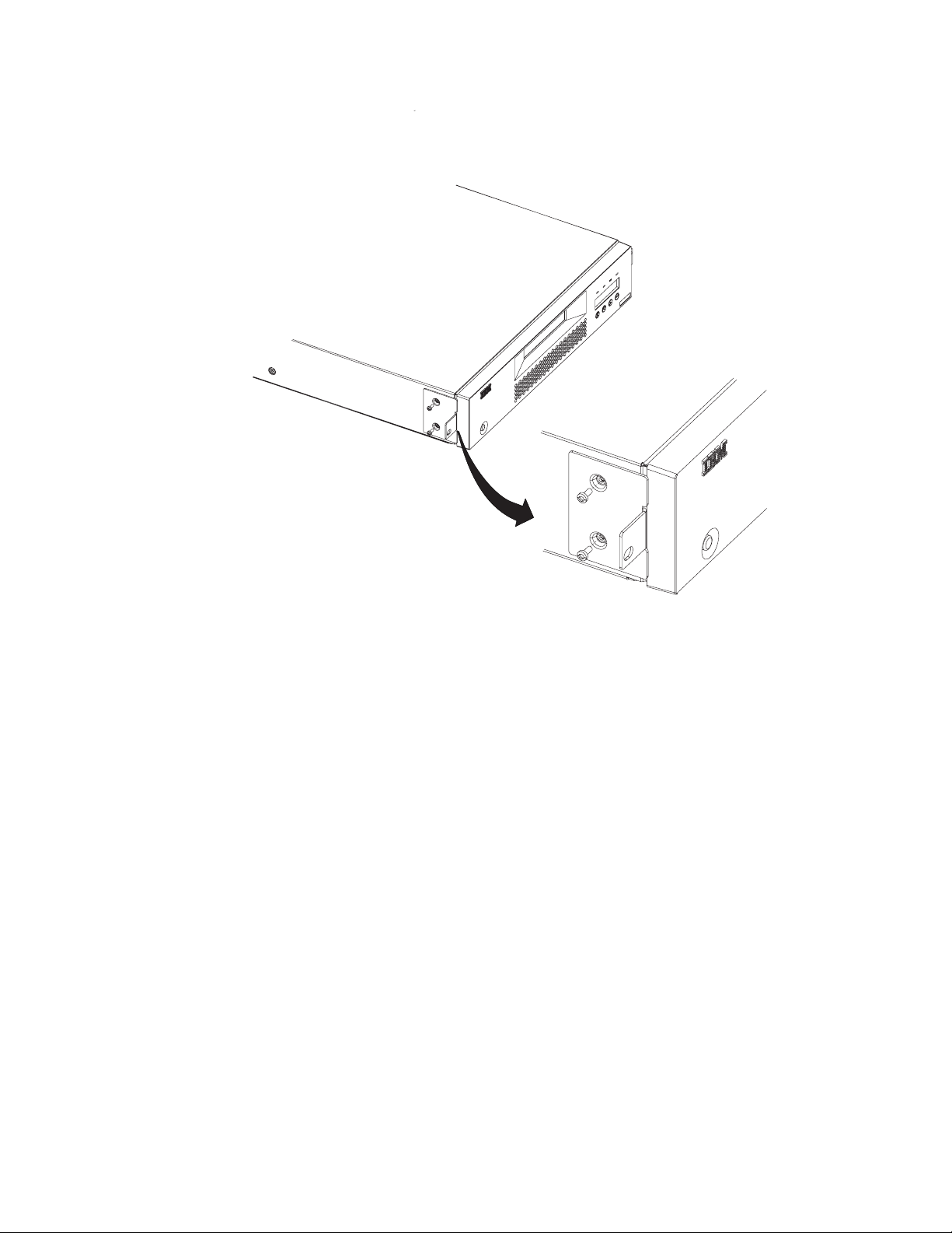
|
a67s0207
|
|
Figure 19. Installing rack-mount brackets
|
|
|
__ 2. Using the Torx wrench, remove the two screws on each side of the
Autoloader cover.
__ 3. Position the correct bracket, as determined in Step 1, on each side of the
Autoloader and secure by replacing the original screws (see Figure 19).
Secure the Autoloader to the Rack
To secure the Autoloader to the rack:
__ 1. From the front of the rack, position the Autoloader on the shelf flanges
between the support rails. Slide it toward the rear of the rack until the
brackets contact the rack’s mounting holes.
|
|
Note: Make sure that the tabs on the back of each shelf flange are fully
engaged in the slots at the rear of the Autoloader.
34 IBM 3581 Autoloader Models L28/L38/L3H and F28/F38/F3H Setup, Operator, and Service Guide
Page 59

3
1
T
N
O
R
RONT
F
-
2
2-F
1
2
a67s0208
Figure 20. Installing the Autoloader in a rack
|
|
|
|
|
|
__ 2. Place one screw and washer from the Rack Mount Kit into the hole in the
front of each bracket. The screws should line up with the holes containing
the remaining installed clip-nuts. Use a #2 Phillips screwdriver to tighten the
screws.
For information on connecting a power cable to an Autoloader installed in a
Note:
rack, see “Step 9. Connect Power” on page 36.
Setup Guide: Installation 35
Page 60

Step 9. Connect Power
|
|
|
|
|
|
|
|
|
|
|
|
|
|
|
|
|
|
|
|
|
|
|
Desktop Installation
To connect power to a desktop Autoloader:
__ 1. Plug the power cord into the receptacle at the rear of the Autoloader, then
plug the other end into a grounded electrical outlet.
__ 2. Power on the Autoloader. The Autoloader will verify the drive configuration
and status, build a valid cartridge inventory log, and calibrate the robotic
cartridge loader. The OCP’s green READY/ACTIVITY LED (light-emitting
diode) will blink during this initialization process. When the Autoloader
completes the Power-On Self Test (POST) for the drive and the library, the
green READY/ACTIVITY LED will stop blinking. The Autoloader will be in
automatic mode (the default mode) and SEQ will appear in the lower right
corner of the OCP display.
For information about the Autoloader’s modes of operation, see “CHANGE
LDR MODE” on page 92.
If a failure occurred, the red ERROR LED will light up and an error message
will be displayed on the OCP. Refer to “Troubleshooting” on page 163.
__ 3. If the power on is successful, run the Drive Recalibration test and the
Library Verify test.
Rack Installation
To connect power to an Autoloader installed in a rack:
1. Connect the PCC cable (included with your Rack Mount Kit) to the rear of the
Autoloader.
a67s0273
Figure 21. PCC cable
|
|
|
|
|
|
|
|
|
|
|
|
|
|
|
|
2. Connect the other end of the PCC cable to your rack’s power strip.
3. Power on the power strip.
4. Power on the Autoloader. The Autoloader will verify the drive configuration
and status, build a valid cartridge inventory log, and calibrate the robotic
cartridge loader. The OCP’s green READY/ACTIVITY LED (light-emitting
diode) will blink during this initialization process. When the Autoloader
completes the Power-On Self Test (POST) for the drive and the library, the
green READY/ACTIVITY LED will stop blinking. The Autoloader will be in
automatic mode (the default mode) and SEQ will appear in the lower right
corner of the OCP display.
For information about the Autoloader’s modes of operation, see “CHANGE
LDR MODE” on page 92.
If a failure occurred, the red ERROR LED will light up and an error message
will be displayed on the OCP. Refer to “Troubleshooting” on page 163.
5. If the power on is successful, run the Drive Recalibration test and the Library
Verify test.
36 IBM 3581 Autoloader Models L28/L38/L3H and F28/F38/F3H Setup, Operator, and Service Guide
Page 61

|
|
|
|
|
|
|
|
|
|
Running a Drive Recalibration Test
To run a drive recalibration test, complete the following steps:
__ Step 1. Navigate to the Diagnostic Menu.
__ Step 2. Press Enter and then Next to access the DRIVE DIAG menu.
__ Step 3. Press Enter then press Next until Recalibration is displayed.
__ Step 4. Press Enter to initiate the test.
__ Step 5. OCP prompts you to insert a cartridge into Slot 1 through the I/O
door.
__ Step 6. When the calibration diagnostic is complete, remove the cartridge from
the I/O door and press Enter.
LIBRARY VERIFY Test
Complete the following steps to run LIBRARY VERIFY.
__ 1. After pressing Enter on the OCP at the ONLINE screen:
a. Press Next four times to navigate to the Diagnostic Menu.
b. Press Enter to navigate to the LOADER DIAG menu item.
c. Press Enter to access LIBRARY VERIFY.
d. Press Enter to begin the verification.
e. On the OCP display, you will be asked to insert a cartridge.
f. When the I/O Door opens, insert a blank cartridge or a scratch cartridge.
The I/O Door will close automatically.
g. While the test is running, the OCP will display library status.
v If the test PASSED, proceed to the next step.
v If the test FAILED, refer to “Troubleshooting” on page 163.
h. Press Enter.
i. When prompted by the OCP display, remove the cartridge.
j. Press Enter to end the test.
2. Power off the Autoloader.
__
Setup Guide: Installation 37
Page 62

Step 10. Connect the Autoloader to Your Server (Host)
|
|
|
|
The Autoloader Model L28/L38/L3H can be attached to a SCSI/LVD system. The
model L28 can also attach to a SCSI-LVD/HVD system using the optional HVD
Converter. The Autoloader Model F28/F38/F3H contains a Fibre Channel drive
that can be attached to a Fibre Channel system.
Cabling is required for the tape drive interface and the RMU, if installed, in order
for your server (host) to communicate with the Autoloader. The sections that
follow include information on options cabling and drive interface connections.
|
Ensure that Autoloader power is OFF.
RMU Cabling
To connect the RMU to a network switch or hub or directly to a server (host):
1. Plug an Ethernet cable into the RMU mounted on the rear of the Autoloader.
2. Plug the other end of the Ethernet cable into your network switch or hub.
If you are plugging the RMU directly into a PC, use a special crossover
Note:
Ethernet cable (not supplied).
SCSI Interface
A SCSI cable is required for each server connection to a SCSI bus. An LVD SCSI
terminator is included in your ship group.
Attention: Be sure to install the appropriate SCSI host bus adapter and software
on your server (host). For more information, refer to your server (host)
documentation and application software.
|
Attaching to a SCSI-LVD System
Attention
|
Be sure to use LVD cables with the LVD converter.
To attach your Autoloader to a SCSI-LVD system, complete the following steps:
__ Step 1. Plug the SCSI cable (included in your ship group) into the top SCSI
receptacle (1) on the rear panel of your Autoloader.
38 IBM 3581 Autoloader Models L28/L38/L3H and F28/F38/F3H Setup, Operator, and Service Guide
Page 63

2
1
a67s0233
Figure 22. SCSI receptacles on rear of Autoloader
__ Step 2. Plug the LVD SCSI terminator (or another SCSI cable connecting to
another SCSI device) into the bottom SCSI receptacle (2) on the rear
panel of your Autoloader.
__ Step 3. Connect the SCSI cable to your server (host).
|
Attaching to a SCSI-HVD System
To attach your Autoloader to a SCSI-HVD system, complete the following steps:
1. Install the HVD Converter on the rear panel of your Autoloader (see “Step 5.
Install the Optional HVD Converter (L28 Models Only)” on page 23).
2. Plug the HVD SCSI cable into the top SCSI receptacle (1) on the HVD
converter.
1
2
a67s0232
Figure 23. SCSI receptacles on HVD Converter
3. Plug the HVD Differential terminator into the bottom SCSI receptacle (2) on
the HVD converter.
4. Connect the SCSI cable to the server (host).
Fibre Channel Interface
To attach your Autoloader to a Fibre Channel system, complete the following steps:
__ 1. Plug the fiber cable (included in your ship group) into the rear panel of
your Autoloader.
Setup Guide: Installation 39
Page 64

1
Figure 24. Fibre Channel receptacle
__ 2. Connect the fiber cable to your network switch or hub or directly into your
server (host).
a67s0204
40 IBM 3581 Autoloader Models L28/L38/L3H and F28/F38/F3H Setup, Operator, and Service Guide
Page 65

Step 11. Power on the Autoloader
To power on the Autoloader, press and release the POWER button located on the
front panel.
If an RMU is installed, look on the rear panel of the Autoloader and verify that the
RMU’s green LED is on. If the green LED is not on, see “Removing/Replacing the
RMU” on page 212 for instructions on reinstalling the RMU. If the green LED is
still not on after reinstallation, contact IBM Technical Support (see “Contacting IBM
Technical Support” on page 200).
Configuring Your Autoloader
|
|
|
|
|
|
|
|
|
Saving / Restoring VPD on the RMU
|
|
|
|
|
|
|
|
|
|
|
|
|
|
|
|
Depending on the model, see one of the following to configure your Autoloader:
v “Configuring a Model L28/L38/L3H Autoloader” on page 91
v “Configuring a Model F28/F38/F3H Autoloader” on page 99
complete configuration for either model:
To
v See “Completing Configuration of Autoloader” on page 107.
It is recommended that you first read “Menus” on page 45 to familiarize
Note:
yourself with the OCP interface, access protocol and menus.
Note:
If an RMU is installed, after all items in the Vital Product Data (VPD) ″save″
list below are set to the desired values, you will be instructed at the end of
the configuration instructions to access the Reset page in the Configuration
Menu on the RMU to ″save″ these values on the actual RMU module
installed on the rear panel of the Autoloader. These items are ″saved″ for
possible use at a later date should the base Autoloader unit need to be
replaced. This RMU feature allows for quick VPD restore rather than having
to manually reinstall each desired value using the OCP. The above
mentioned page (Reset) also contains a ″restore″ button selection. In
addition, if any of these items are changed at any time after install, the
″save″ button on the above mentioned RMU page should be pressed to
always save the latest values. Machine serial number and World Wide Node
Name (WWNN) are ″saved″ from the original machine and ″restored″ to
VPD of the replacement machine to enable various network hosts to see the
″same″ Autoloader without having to re-configure the network.
|
|
|
|
|
|
|
|
|
Model L28/L38/L3H VPD Items Saved on RMU:
v SCSI ID
v Operating Mode
v SCSI Drive Speed
v BCR Enablement
v Machine Serial Number
F28/F38/F3H VPE Items Saved on RMU:
Model
v Loop ID
v Loop Port Type
Setup Guide: Installation 41
Page 66

|
|
|
|
|
v Operating Mode
v Fibre Channel Drive Speed
v BCR Enablement
v Machine Serial Number
v WWNN
42 IBM 3581 Autoloader Models L28/L38/L3H and F28/F38/F3H Setup, Operator, and Service Guide
Page 67

|
Part 2. Operator Guide
Menus . . . . . . . . . . . . . . . .45
Access Protocol . . . . . . . . . . . . .45
Operator Control Panel (OCP) . . . . . . . .46
Power On Display . . . . . . . . . . .47
Home Screen . . . . . . . . . . . . .47
Online Menu . . . . . . . . . . . . . .49
Information Menu . . . . . . . . . . .49
| |
LOADER INFO . . . . . . . . . . .50
DRIVE INFO . . . . . . . . . . . .52
Go Offline . . . . . . . . . . . . . .53
Going Offline with Password Protection OFF 53
Going Offline with Password Protection ON 54
Model L28/L38/L3H (SCSI Drive) Offline Menu . .55
| |
Information Menu . . . . . . . . . . .55
| |
Commands Menu . . . . . . . . . . .55
BULK EXCHANGE . . . . . . . . . .56
IMPORT . . . . . . . . . . . . .56
EXPORT . . . . . . . . . . . . .57
LOAD CARTRIDGE . . . . . . . . .58
UNLOAD CARTRIDGE . . . . . . . .58
CLEAN DRIVE . . . . . . . . . . .58
RE-INVENTORY . . . . . . . . . .60
Configuration Menu . . . . . . . . . .60
| |
| |
RESET . . . . . . . . . . . . . .60
CHANGE SCSI ID . . . . . . . . . .61
SCSI SPEED . . . . . . . . . . . .61
DRIVE FW UPGRADE FROM FMR TAPE . .62
| |
CHANGE LDR MODE . . . . . . . .62
LOOP MODE . . . . . . . . . . . .63
| |
| |
AUTOLOAD MODE . . . . . . . . .63
NET PARAMETER . . . . . . . . . .64
BARCODE READER . . . . . . . . .65
PROTECTION MODE . . . . . . . . .66
SERIAL NUMBER . . . . . . . . . .67
Diagnostic Menu . . . . . . . . . . .67
LOADER DIAG . . . . . . . . . . .67
DRIVE DIAG . . . . . . . . . . . .70
Go Online . . . . . . . . . . . . . .74
Model F28/F38/F3H (Fibre Channel Drive) Offline
|
Menu . . . . . . . . . . . . . . . .75
||
Information Menu . . . . . . . . . . .76
Commands Menu . . . . . . . . . . .76
Configuration Menu . . . . . . . . . .76
RESET . . . . . . . . . . . . . .76
CHANGE LOOP ID . . . . . . . . .76
FIBRE CHANNEL . . . . . . . . . .77
| |
WW NODE NAME . . . . . . . . . .77
FIBRE SPEED . . . . . . . . . . . .78
DRIVE FW UPGRADE FROM FMR TAPE . .78
CHANGE LDR MODE . . . . . . . .78
LOOP MODE . . . . . . . . . . . .79
AUTOLOAD MODE . . . . . . . . .80
NET PARAMETER . . . . . . . . . .80
BARCODE READER . . . . . . . . .82
PROTECTION MODE . . . . . . . . .82
SERIAL NUMBER . . . . . . . . . .83
Diagnostic Menu . . . . . . . . . . .84
Go Online . . . . . . . . . . . . . .84
Configuration . . . . . . . . . . . . .85
Passwords . . . . . . . . . . . . . . .85
OCP Password . . . . . . . . . . . .85
Going Offline with Password Protection OFF 85
Going Offline with Password Protection ON 85
RMU Passwords . . . . . . . . . . . .86
Logging in the First Time . . . . . . . .86
Serial Communication Password . . . . . .86
Using HyperTerminal . . . . . . . . .86
Configuring a Model L28/L38/L3H Autoloader . .91
Step 1. Go Offline Using the OCP . . . . . .91
Step 2. Change SCSI ID . . . . . . . . .91
Step 3. Change SCSI Speed . . . . . . . .92
Step 4. Change the Operating Mode . . . . .92
CHANGE LDR MODE . . . . . . . .92
LOOP MODE . . . . . . . . . . . .93
AUTOLOAD MODE . . . . . . . . .94
Step 5. Configure the RMU . . . . . . . .95
Configuring Network Parameters . . . . .95
Step 6. Configure the BCR . . . . . . . .96
Step 7. Cycle Autoloader Power . . . . . .96
Step 8. Set Protection Mode ON or OFF . . . .97
Step 9. Save Vital Product Data (Autoloader with
RMU Only) . . . . . . . . . . . . .97
Step 10. Update Autoloader Configuration Form 98
Configuring a Model F28/F38/F3H Autoloader . .99
Step 1. Go Offline Using the OCP . . . . . .99
Step 2. Change Loop ID . . . . . . . . .99
Step 3. Select Fibre Channel Port . . . . . . 100
Step 4. Enter WW Node Name . . . . . . 100
Step 5. Change Fibre Channel Speed . . . . 100
Step 6. Change the Operating Mode . . . . . 101
CHANGE LDR MODE . . . . . . . . 101
LOOP MODE . . . . . . . . . . . 102
AUTOLOAD MODE . . . . . . . . . 102
Step 7. Configure the RMU . . . . . . . . 103
Configuring Network Parameters using the
OCP . . . . . . . . . . . . . . 103
Step 8. Configure the BCR . . . . . . . . 104
Step 9. Cycle Autoloader Power . . . . . . 104
Step 10. Set Protection Mode ON or OFF . . . 105
Step 11. Save Vital Product Data (Autoloader
with RMU Only) . . . . . . . . . . . 105
Step 12. Update Autoloader Configuration Form 106
Completing Configuration of Autoloader . . . . 107
Step 1. Import Cartridges . . . . . . . . 107
BULK EXCHANGE . . . . . . . . . 107
IMPORT . . . . . . . . . . . . . 108
Step 2. Configure RMU User Accounts . . . . 108
Starting the RMU . . . . . . . . . . 108
Logging in the First Time . . . . . . . 108
Configuring User Accounts . . . . . . . 109
Step 3. Install Device Drivers . . . . . . .110
© Copyright IBM Corp. 2004, 2005 43
Page 68

Step 4. Configure the Autoloader to the Server
(Host) . . . . . . . . . . . . . . .110
Step 5. Update Firmware . . . . . . . . 111
My Support . . . . . . . . . . . . 111
Via Serial Port . . . . . . . . . . . 111
Via RMU . . . . . . . . . . . . .118
Via SCSI / Fibre . . . . . . . . . .118
Step 6. Register for My Support . . . . . . 121
Remote Management Unit (RMU) . . . . . . 123
Access Protocol . . . . . . . . . . . . . 123
Login . . . . . . . . . . . . . . . . 124
Help . . . . . . . . . . . . . . . . 125
Quick Status . . . . . . . . . . . . . . 125
Status Icons . . . . . . . . . . . . . 125
Information Menu . . . . . . . . . . . . 126
Autoloader (Models L28/L38/L3H and
|
F28/F38/F3H) . . . . . . . . . . . . 126
||
Drive (Models L28/L38/L3H and
|
F28/F38/F3H) . . . . . . . . . . . . 127
||
Status Menu . . . . . . . . . . . . . . 128
Autoloader (Models L28/L38/L3H and
|
F28/F38/F3H) . . . . . . . . . . . . 128
||
Media (Models L28/L38/L3H and
|
F28/F38/F3H) . . . . . . . . . . . . 129
||
Configuration Menu . . . . . . . . . . . 130
Device (Model L28/L38/L3H) . . . . . . . 130
||
Device (Model F28/F38/F3H) . . . . . . . 131
||
Network (Models L28/L38/L3H and
|
F28/F38/F3H) . . . . . . . . . . . . 132
||
User (Models L28/L38/L3H and F28/F38/F3H) 133
||
RTC (Models L28/L38/L3H and F28/F38/F3H) 134
Log (Models L28/L38/L3H and F28/F38/F3H) 134
||
Event Notification (Models L28/L38/L3H and
|
F28/F38/F3H) . . . . . . . . . . . . 135
||
Reset (Models L28/L38/L3H and F28/F38/F3H) 136
||
Maintenance Menu . . . . . . . . . . . 137
Operations (Models L28/L38/L3H and
|
F28/F38/F3H) . . . . . . . . . . . . 137
||
General Diagnostic (Models L28/L38/L3H and
|
F28/F38/F3H) . . . . . . . . . . . . 138
||
Advanced Diagnostic (Models L28/L38/L3H
and F28/F38/F3H) . . . . . . . . . . 138
Firmware (Models L28/L38/L3H and
F28/F38/F3H) . . . . . . . . . . . . 139
Reset (Models L28/L38/L3H and F28/F38/F3H) 139
||
Logs Menu . . . . . . . . . . . . . . 140
Loader (Models L28/L38/L3H and
|
F28/F38/F3H) . . . . . . . . . . . . 140
||
Drive (Models L28/L38/L3H and
|
F28/F38/F3H) . . . . . . . . . . . . 141
||
Logout . . . . . . . . . . . . . . . 142
Ensure Proper Packaging . . . . . . . . 148
Provide Proper Acclimation and Environmental
Conditions . . . . . . . . . . . . . 149
Perform a Thorough Inspection . . . . . . 149
Handle the Cartridge Carefully . . . . . . 150
Examples of Cartridge Problems . . . . . . 150
Environmental and Shipping Specifications for
Tape Cartridges . . . . . . . . . . . . 151
Repositioning or Reattaching a Leader Pin . . . 152
Repositioning a Leader Pin . . . . . . . . 152
Reattaching a Leader Pin . . . . . . . . 154
Disposing of Tape Cartridges . . . . . . . . 158
Ordering Media Supplies . . . . . . . . . 159
Ordering Bar Code Labels . . . . . . . . 160
Media . . . . . . . . . . . . . . . 143
Data Cartridge . . . . . . . . . . . . . 144
Cleaning Cartridge . . . . . . . . . . . 145
Bar Code Label . . . . . . . . . . . . . 145
Guidelines for Using Bar Code Labels . . . . 146
Setting the Write-Protect Switch . . . . . . . 147
Handling Cartridges . . . . . . . . . . . 147
Provide Training . . . . . . . . . . . 148
44 IBM 3581 Autoloader Models L28/L38/L3H and F28/F38/F3H Setup, Operator, and Service Guide
Page 69

Menus
The Menus chapter gives information on access protocol for the OCP, RMU, and
serial communication, describes the components of the Operator Control Panel
(OCP), and gives instructions on how to use the Autoloader’s menus via the OCP.
v “Online Menu” on page 49
v “Model L28/L38/L3H (SCSI Drive) Offline Menu” on page 55
v “Model F28/F38/F3H (Fibre Channel Drive) Offline Menu” on page 75
Access Protocol
All three Autoloader user interfaces (OCP, RMU, and serial) can simultaneously be
active on the lowest level (Information only).
v RMU: Standard user
v OCP: Online
v Serial: lgo (logout)
However,
only one of the three interfaces can be active at any one time on the
Administrator or Service levels (RMU and serial) or at the Offline level (OCP). The
other two can remain active on the lowest level. If an attempt to login is made on
either of the other two while the third has the highest level access, an ″Already
Reserved″ message is displayed. The RMU will only allow access by a Standard
user at the login panel.
For best results:
v If communicating via the OCP, return to the Home Screen before attempting to
communicate via the RMU or serial port.
v If communicating via the RMU, log out before attempting to communicate via
the OCP or serial port.
v If communicating via the serial port, log out before attempting to communicate
via the OCP or RMU
© Copyright IBM Corp. 2004, 2005 45
Page 70

Operator Control Panel (OCP)
The OCP contains four LEDs (light-emitting diodes), a display, and four push
buttons.
1
2
3
4
5
6
7
8
9
a67s0215
Figure 25. Operator Control Panel (OCP)
v LEDs:
– 1READY/ACTIVITY (green)
Turns on any time the Autoloader is powered on and able to function.
This LED should blink whenever there is Autoloader or tape drive activity.
2CLEAN DRIVE (amber)
–
Turns on when the tape drive needs to be cleaned. This LED will turn off
after the drive is cleaned.
3MEDIA ATTENTION (amber)
–
|
|
Turns on when a media failure occurs. This LED will turn off when all
defective, marginal, or invalid cartridges have been exported from the
Autoloader.
4ERROR (red)
–
Turns on when there is an unrecoverable tape drive or Autoloader failure.
This LED will turn on at the same time the error message is displayed on
|
5OCP’s Display
v
the screen and will remain on until the error condition is corrected.
Consists of two lines with 16 characters per line. It displays actions and
status information, menu items or error messages.
v Buttons
– 6CANCEL
- Used to return to the Home Screen from any menu screen.
- Used to return to the corresponding menu screen from any menu’s
commands screens.
7PREVIOUS
–
- Used to move back from one menu screen to the previous menu screen.
46 IBM 3581 Autoloader Models L28/L38/L3H and F28/F38/F3H Setup, Operator, and Service Guide
Page 71

- Used to move back from one command screen to the previous command
screen within the same menu.
8NEXT
–
- Used to move forward from one menu screen to the next menu screen.
- Used to move forward from one command screen to the next command
screen within the same menu.
9ENTER
–
- Used to access the first corresponding command screen from any menu
screen .
- Used to initiate the corresponding operation from any menu’s command
screens .
Power On Display
When the Autoloader powers on, or resets, it goes through several Power On Self
Tests (POST). POST are internally controlled processes that allow the Autoloader to
initialize. While these processes are running, the OCP will display appropriate
information to keep the user informed of the Autoloader’s status.
Home Screen
The Home Screen displays the Autoloader’s current status of the drive (″Drive
empty″ or ″Drive ready″) on the top line and the current cartridge inventory and
operating mode on the bottom line.
Drive empty
------------- SEQ
a67s0229
Figure 26. Operator Control Panel (OCP) Home Screen
The inventory status characters will be represented as follows on the second line of
the display:
v Slot Empty - A dash character (″-″) will be displayed as a placeholder. (Slot Full -
The slot number ″1″ to ″8″ will be displayed.)
v A cartridge that is being loaded, unloaded, imported, exported, or is loaded in
the drive, will be represented by the slot number blinking.
v A cartridge that has been identified as invalid or faulty (and the amber Media
Attention LED is on) will be represented by an exclamation point (!).
current operating mode will be displayed on the second line. The message
The
varies, depending on the Autoloader’s mode of operation:
|
v If the Autoloader is operating in sequential access mode or automatic mode (the
default mode), SEQ displays. If a library command is sent by the host and
received by the Autoloader, SEQ disappears from the display.
v If the Autoloader is operating in random access mode, nothing displays.
the drive detects a write-protected media, the OCP displays ″WP″ on the bottom
|
|
|
|
|
If
line of the display indicating a write-protected media is loaded in the drive. As
soon as the write-protected media is ejected, ″WP is replaced by the current
operating mode. For more information on write-protected media, see “Setting the
Write-Protect Switch” on page 147.
To return to the Home Screen, perform one of the following:
Operator Guide: Menus 47
Page 72

v Suspend all activity on the OCP for one and a half minutes.
v Press the OCP’s Cancel button from the top level of the current menu.
48 IBM 3581 Autoloader Models L28/L38/L3H and F28/F38/F3H Setup, Operator, and Service Guide
Page 73

Online Menu
|
|
|
After powering on the Autoloader, the Online Menu is available. The Online
Menu contains the Information Menu and Go Offline.
HOME (ONLINE)
STATUS
(INV. STATUS)
ANY KEY
>
>
>
INFORMATION
(INV. STATUS)
LOADER INFO.
(INV. STATUS)
>
X
GO OFFLINE
(INV. STATUS)
>
>
DRIVE INFO.
(INV. STATUS)
|
|
Figure 27. Online menu tree
GO ONLINE
(INV. STATUS)
(+)
>
X
ANY KEY
ALREADY
RESERVED
Legend
X
Cancel
Enter
Previous
>
>
Next
a67s0221
|
Information Menu
The Information Menu contains commands that will display such things as
Autoloader and drive serial numbers, model numbers, firmware levels, and error
logs.
To navigate to the Information Menu from the Home Screen:
v Press any button (Cancel, Previous, Next, or Enter) on the OCP.
Operator Guide: Menus 49
Page 74

LOADER INFO
LOADER INFO contains the information that relates specifically to the Autoloader.
LOADER INFO.
(INV. STATUS)
>
>
FIRMWARE REV
XXX
SERIAL NUMBER
0123456789
MACHINE TYPE
1234
MODEL NUMBER
123
CYCLE COUNT
XXX
ERROR LOG
TOTAL XXX
BARCODE READER
(BCR STATUS)
>
>
>
>
>
>
>
>
>
>
>
Legend
X
Cancel
Enter
Previous
>
>
>
>
>
Next
a67s0217
Figure 28. Information Menu LOADER INFO item
Note: Enter the information in this menu on the “Autoloader Configuration Form”
on page 251.
To access the LOADER INFO menu using the OCP:
1. Navigate to the Information Menu (see “Information Menu” on page 49).
2. Press Enter to access the LOADER INFO screen.
3. Press Enter to access the first item in the LOADER INFO menu.
4. Press Next or Previous to navigate through the following menu items:
v FIRMWARE REV - the current Autoloader firmware revision level
v SERIAL NUMBER - this number should match the serial number on the label
located in the lower right corner on the Autoloader’s front panel
v MACHINE TYPE - ″3581″
|
|
v MODEL NUMBER - either L28/L38/L3H (LVD SCSI drive) or F28/F38/F3H
(Fibre Channel drive)
v CYCLE COUNT - the number of times the cartridge carousel has made a
complete cycle.
50 IBM 3581 Autoloader Models L28/L38/L3H and F28/F38/F3H Setup, Operator, and Service Guide
Page 75

v ERROR LOG - displays the error code (XX YY ZZ) and time the error
occurred (ddd.hh.mm.ss.tt)
ERROR LOG
TOTAL: XXX
X
ERROR: XX
XX YY ZZ
X
EVENT TIME: X
ddd:hh:mm:ss:tt
Legend
X
Cancel
Enter
Previous
>
>
Next
a67s0188
Figure 29. Information Menu Error Log for the Autoloader command
After navigating to ERROR LOG using the OCP:
a. Press Enter to access the ERROR: XX screen and to display the error code
(XX YY ZZ).
b. Press Previous to scroll through each previous error entry in the log.
|
c. Press Enter to display EVENT TIME: X of the error (ddd.hh.mm.ss.tt).
d. Press Previous to scroll through other previous event times.
e. Press Cancel:
– One time to return to the corresponding error entry.
– Two times to return to the ERROR LOG screen.
– Three times to return to the LOADER INFO screen.
– Four times to return to the Information Menu screen.
– Five times to return to the Home Screen.
BARCODE READER
v
|
|
|
|
– Press Enter to display the line LOADER BCR LAB X (X = library tape
location). If the tape has a barcode, it will be displayed on the next nine.
Otherwise, the second line will be blank.
– NO BCR FUNCTION will be displayed if the BCR:
- Is not installed
- OR -
- Is installed but not initiated via the Configuration Menu
BCR PRESENT will be displayed if the BCR is installed and initiated via
|
–
the Configuration Menu
|
|
– Press Cancel as many times as necessary to exit and return to the Home
Screen.
Operator Guide: Menus 51
Page 76

DRIVE INFO
DRIVE INFO contains the following information that relates specifically to the
Autoloader’s drive.
DRIVE INFO.
(INV. STATUS)
X
>
PRODUCT REV
1234
>
>
SERIAL NUMBER
0123456789
>
>
SCSI EVT LOG
>
>
ERROR LOG
Legend
X
Cancel
Enter
Previous
>
>
Next
>
a67s0218
Figure 30. Information Menu DRIVE INFO item
Note: Enter the information in this menu on the “Autoloader Configuration Form”
on page 251.
To access the DRIVE INFO menu using the OCP:
1. Navigate to the Information Menu (see “Information Menu” on page 49).
2. Press Enter.
3. Press Next to access the DRIVE INFO screen.
4. Press Enter to access the first menu item in the DRIVE INFO menu.
5. Press Next or Previous to navigate through the following menu items:
v PRODUCT REV. - the current drive firmware revision level
v SERIAL NUMBER - the drive serial number
v SCSI EVT LOG - displays the error number (XX YY ZZ VV NN) and the time
the error occurred (dddd:hh:mm:ss:tt)
SCSI EVT LOG
X
ERROR LOG X
XX YY ZZ VV NN
>
ERROR LOG X
dddd:hh:mm:ss:tt
>
Legend
X
Cancel
Enter
Previous
>
>
Next
a67s0 173
Figure 31. Information Menu SCSI Event Log for the drive command
After navigating to SCSI EVT LOG using the OCP:
a. Press Enter to access the ERROR LOG X screen and to display the error
number (XX YY ZZ VV NN).
b. Press Enter to display the time the error occurred (dddd:hh:mm:ss:tt).
52 IBM 3581 Autoloader Models L28/L38/L3H and F28/F38/F3H Setup, Operator, and Service Guide
Page 77

c. Press Cancel:
– One time to return to the corresponding error entry.
– Two times to return to the SCSI EVT LOG screen. Press Next to access
the next menu item.
– Three times to return to the DRIVE INFO screen.
– Four times to return to the Information Menu screen.
– Five times to return to the Home Screen.
ERROR LOG - displays the error number (XX YY ZZ VV NN) and the time
v
the error occurred (dddd:hh:mm:ss:tt)
ERROR LOG
X
ERROR LOG X
XX YY ZZ VV NN
>
ERROR LOG X
dddd:hh:mm:ss:tt
>
Legend
X
Cancel
Enter
Previous
>
>
Next
a67s0187
Figure 32. Information Menu Error Log for the drive command
After navigating to ERROR LOG using the OCP:
a. Press Enter to access the ERROR LOG X screen and to display the error
number (XX YY ZZ VV NN).
b. Press Enter to display the time the error occurred (dddd:hh:mm:ss:tt).
c. Press Cancel:
v One time to return to the corresponding error entry.
v Two times to return to the ERROR LOG screen. Press Next to access the
next menu item.
v Three times to return to the DRIVE INFO screen.
v Four times to return to the Information Menu screen.
v Five times to return to the Home Screen.
Go Offline
Password protection for going Offline to the Autoloader via the OCP can be turned
OFF (default setting) or ON.
Going Offline with Password Protection OFF
To access all menus using the OCP with password protection OFF (the default
setting):
1. Power on the Autoloader. When the Power On Self Test is complete, the Home
Screen will appear on the OCP display.
2. Press any key on the OCP (Cancel, Previous, Next, or Enter) to access the
Information Menu.
3. Press Next to access Go Offline.
4. Press Enter to Go Offline and make all menus accessible.
|
|
5. Press Next, as necessary, to verify that all Offline menus (Information,
Commands, Configuration, Diagnostic, Go Online) are available.
Operator Guide: Menus 53
Page 78

Going Offline with Password Protection ON
To go offline with password protection activated:
1. Power on the Autoloader. When the Power On Self Test is complete, the Home
Screen will appear on the OCP display.
2. Press any key on the OCP (Cancel, Previous, Next, or Enter) to access the
Information Menu.
3. Press Next to access the Go Offline display.
4. Press Enter.
|
|
5. Using Next and Previous, enter the first numerical digit of the PIN (password)
then press Enter to move to the next digit in the PIN (password). Repeat this
step for each digit in the password.
6. If GO OFFLINE PASSED is displayed, press Enter to complete going offline. If
GO OFFLINE FAILED displays, the PIN (password) was incorrect. Press Cancel
and repeat this procedure.
54 IBM 3581 Autoloader Models L28/L38/L3H and F28/F38/F3H Setup, Operator, and Service Guide
Page 79

Model L28/L38/L3H (SCSI Drive) Offline Menu
|
|
|
||
|
|
|
After logging in from an RMU, or going offline from the OCP, to an Autoloader
with a SCSI drive (Model L28/L38/L3H), the user has access to the Model
L28/L38/L3H Offline Menu shown in Figure 33.
ANY
KEY
Figure 33. Autoloader Model L28/L38/L3H Offline Menu
>
INFORMATION
(INV. STATUS)
>
LOADER INFO.
(INV. STATUS)
DRIVE INFO.
(INV. STATUS)
>
>
COMMANDS
(INV. STATUS)
>
>
>
BULK EXCHANGE
(INV. STATUS)
>
>
IMPORT
(INV. STATUS)
>
EXPORT
(INV. STATUS)
LOAD CARTRIDGE
(INV. STATUS)
UNLOAD CARTRIDGE
(INV. STATUS)
CLEAN DRIVE
(INV. STATUS)
RE-INVENTORY
(INV. STATUS)
>
>
CONFIGURATION
(INV. STATUS)
>>
RESET
(INV. STATUS)
>
>
CHANGE SCSI I.D.
(INV. STATUS)
>
>
SCSI SPEED
AUTOMATIC
>
>
>
>
>
>
>
>
>
DRIVE FW
UPGRADE
FROM FMR TAPE
CHANGE LDR MODE
AUTOMATIC
LOOP MODE
OFF
AUTOLOAD MODE
OFF
NET PARAMETER
(INV. STATUS)
BARCODE
READER
on / off
PROTECTION MODE
OFF
SERIAL NUMBER
0123456789
>
>
DIAGNOSTIC
(INV. STATUS)
LOADER
DIAGNOSTIC
(INV. STATUS)
>
>
>
>
>
>
>
>
>
>
>
>
DRIVE
DIAGNOSTIC
(INV. STATUS)
>
>
>
>
>
>
>
>
>
(+) (+)
> >
GO ONLINE
(INV. STATUS)
>
X XXX
HOME (ONLINE)
MENU
>
>
>
(INV. STATUS)
Legend
X
Cancel
Enter
Previous
>
>
Next
a67s0170
|
|
|
Information Menu
See “Information Menu” on page 49.
|
|
|
|
|
Commands Menu
To navigate to the Commands Menu from the Home Screen using the OCP:
v Press any button (Cancel, Previous, Next, or Enter) on the OCP to display the
Information Menu screen.
v Press Next to display the Commands Menu screen.
Operator Guide: Menus 55
Page 80

|
|
|
|
|
|
BULK EXCHANGE
BULK EXCHANGE enables the user to import or export all cartridges. Operation
begins with Slot 1. If a cartridge is available, it will be exported. It is up to the user
to import a new cartridge or to move to Slot 2. The same procedure repeats for the
remainder of the eight slots.
BULK EXCHANGE
(INV. STATUS)
X
BULK EXCHANGE
IMPORT/EXPORT
Legend
X
Cancel
Enter
Previous
>
>
Next
a67s0219
Figure 34. Commands Menu BULK EXCHANGE command
|
|
|
|
|
|
|
|
|
|
|
|
|
To access BULK EXCHANGE using the OCP:
1. Navigate to the Commands Menu (see “Commands Menu” on page 55).
2. Press Enter to access BULK EXCHANGE.
3. Press Enter to initiate the importing and/or exporting of cartridges.
4. When the I/O Door opens, remove the ejected cartridge or proceed to the next
step.
5. Do one of the following:
v Insert another cartridge gently pushing the cartridge through the I/O Door
until the cartridge can be pushed no farther.
v Press Enter to export the next cartridge.
v Press Cancel to terminate BULK EXCHANGE.
When all cartridges have been imported and/or exported, the Autoloader will
6.
return to the Home Screen.
|
|
|
|
IMPORT
The IMPORT command allows the user to insert and choose a destination slot for a
cartridge in the Autoloader.
DOOR STATUS
CART.
Legend
X
Cancel
Enter
Previous
>
>
Next
INSERTED
IMPORT
(INV. STATUS)
X X
IMPORT TO:
SLOT ##
IMPORT STATUS
DOOR STATUS
INSERT
CARTRIDGE
SLOT XX
a67s0171
Figure 35. Commands Menu IMPORT command
|
|
|
|
|
|
|
|
To access IMPORT using the OCP:
1. Navigate to the Commands Menu (see “Commands Menu” on page 55).
2. Press Enter then Next to access IMPORT.
3. Press Enter to display the IMPORT TO: screen.
4. Use the Next and Previous to select the number of the slot to which the
cartridge is to be imported. (Only those slots that are empty will be available
for selection.)
5. Press Enter to initiate the procedure.
56 IBM 3581 Autoloader Models L28/L38/L3H and F28/F38/F3H Setup, Operator, and Service Guide
Page 81

|
|
|
|
|
|
|
|
|
|
|
6. When the I/O Door opens, insert a cartridge. The Autoloader will import the
cartridge, close the I/O Door, and insert the cartridge into the selected slot.
7. Repeat Steps 4 through 6 until all cartridges have been imported.
8. When the last cartridge has been inserted into its slot, press Cancel to return to
the IMPORT screen.
9. Press Cancel to prompt the BCR (if installed) to re-inventory all cartridges and
return to the Home Screen.
EXPORT
The EXPORT command allows the user to remove a cartridge from a selected slot
in the Autoloader.
DOOR STAT US
(implied IMPORT)
X
DOOR STATUS
REMOVE
CARTRIDGE
PRESS ENTER
Legend
X
Cancel
Enter
Previous
>
>
Next
EXPORT
(INV. STATUS)
X
EXPORT FROM:
SLOT ##
EXPORT STATUS
a67s0184
Figure 36. Commands Menu EXPORT command
|
|
|
To access EXPORT using the OCP:
1. Navigate to the Commands Menu (see “Commands Menu” on page 55).
2. Press Enter then Next or Previous, as necessary, until EXPORT is displayed.
3. Press Enter to display the EXPORT FROM: screen.
4. Use the Next and Previous to select the number of the slot from which the
cartridge is to be exported. (Only those slots containing cartridges will be
available for selection.)
5. Press Enter to initiate the procedure.
6. When the I/O Door opens, remove the cartridge.
7. Press Enter.
8. To export another cartridge, repeat Steps 4 through 7 until all cartridges have
been exported. Otherwise, proceed to Step 9.
9. Press Cancel:
v One time to return to the EXPORT SLOT x screen.
v Two times to prompt the BCR (if installed) to re-inventory all cartridges and
return to the Home Screen
Operator Guide: Menus 57
Page 82

LOAD CARTRIDGE
The LOAD CARTRIDGE command allows the user to insert a selected cartridge in
the Autoloader into the drive.
X
LOAD CARTRIDGE
(INV. STATUS)
UNLOAD CARTRIDGE
(INV. STATUS)
LOAD CARTRIDGE
SLOT ##
UNLOAD STATUS
LOAD STATUS
ANY KEY
Figure 37. Commands Menu LOAD CARTRIDGE and UNLOAD CARTRIDGE commands
To access LOAD CARTRIDGE using the OCP:
1. Navigate to the Commands Menu (see “Commands Menu” on page 55).
|
|
2. Press Enter then Next or Previous, as necessary, until LOAD CARTRIDGE is
displayed.
3. Press Enter to display the LOAD CARTRIDGE SLOT # screen.
4. Use Next and Previous to select the number of the slot of the cartridge to be
loaded into the drive.
5. Press Enter to initiate the procedure.
6. When the cartridge has been loaded into the drive, the Autoloader will return
to the Home Screen.
ANY KEY
Legend
X
Cancel
Enter
Previous
>
>
Next
a67s0185
UNLOAD CARTRIDGE
The UNLOAD CARTRIDGE allows the user to remove a cartridge from the drive
and return it to its home slot (see Figure 37).
To access UNLOAD CARTRIDGE using the OCP:
1. Navigate to the Commands Menu (see “Commands Menu” on page 55).
|
|
2. Press Enter then Next or Previous, as necessary, until UNLOAD CARTRIDGE is
displayed.
3. Press Enter to unload the cartridge currently in the drive.
4. When the cartridge has been returned to its home slot, the Autoloader will
return to the Home Screen.
CLEAN DRIVE
When the amber CLEAN DRIVE LED on the OCP turns on (the second LED from
the left), the drive must be cleaned to ensure optimum drive performance and to
safeguard your media.
The CLEAN DRIVE command allows the user to initiate a cleaning of the drive.
The user will be prompted to insert a cartridge in the I/O Door if a cleaning
cartridge does not currently reside in the Autoloader.
58 IBM 3581 Autoloader Models L28/L38/L3H and F28/F38/F3H Setup, Operator, and Service Guide
Page 83

CLEAN DRIVE
(INV. STATUS)
Full Carousel?
YES
NO
IMPORT STATUS
DOOR
No Slot free
for transfer?
ANY KEY
COMMANDS
(INV. STATUS)
STATUS
INSERT
CARTRIDGE
SLOT n
DOOR
STATUS
CART.
INSERTED
IMPORT & LOAD
STATUS
DOOR
STATUS
Cleaning
Cartridge?
YES
Drive cleaning
(INV. STATUS)
UNLOAD &
EXPORT
STATUS
"TAPE EJECTED
BY DRIVE"
REMOVE CARTRIDGE
PRESS ENTER
DOOR
STATUS
CURRENT STATUS
(HOME SCREEN)
NO
"TAPE EJECTED
BY DRIVE"
Legend
X
Cancel
Enter
Previous
>
>
Next
a67s0172
Figure 38. Commands Menu CLEAN DRIVE command
To access CLEAN DRIVE using the OCP:
1. Navigate to the Commands Menu (see “Commands Menu” on page 55).
|
|
2. Press Enter then Next or Previous, as necessary, until CLEAN DRIVE is
displayed.
3. Press Enter.
Operator Guide: Menus 59
Page 84

4. If there are eight cartridges (all slots are full) in your Autoloader, press Cancel
to return to the Commands Menu screen and EXPORT one data cartridge. If
there are less than eight cartridges (all slots are not full) in your Autoloader,
proceed to the next step.
5. When the I/O Door opens, insert a cleaning cartridge.
6. When the cleaning is complete, remove the ejected cleaning cartridge from the
I/O Door.
7. Press Enter to return to the Home Screen.
RE-INVENTORY
The RE-INVENTORY command allows the BCR (if installed) to scan all cartridges
in the Autoloader to update the cartridge inventory.
RE-INVENTORY
(INV. STATUS)
INVENTORY
STATUS
ANY KEY
Figure 39. Commands Menu RE-INVENTORY command
To access RE-INVENTORY using the OCP:
1. Navigate to the Commands Menu (see “Commands Menu” on page 55).
|
|
2. Press Enter then Next or Previous, as necessary, until RE-INVENTORY is
displayed.
3. Press Enter to initiate the inventory.
4. The Autoloader will return to the Home Screen and the updated inventory will
be displayed on the second line.
Legend
X
Cancel
Enter
Previous
>
>
Next
a67s0186
Configuration Menu
The Configuration Menu allows the administrator to setup or change SCSI IDs,
SCSI speed, operating mode, network parameters, as well as, initializing the BCR.
To navigate to the Configuration Menu from the Home Screen using the OCP:
v Press any button (Cancel, Previous, Next, or Enter) on the OCP to display the
Information Menu screen.
|
v Press Next until the Configuration Menu screen displays.
RESET
RESET restarts the Autoloader and is used when initiating configuration changes.
RESET
(INV. STATUS)
RESET STATUS
CURRENT STATUS)
(HOME SCREEN)
Figure 40. Configuration Menu’s RESET command
To access RESET using the OCP:
1. Navigate to the Configuration Menu (see “Configuration Menu”).
2. Press Enter to access RESET.
3. Press Enter to initiate the reset.
4. When the reset is complete, the OCP will display the Home Screen.
Legend
X
Cancel
Enter
Previous
>
>
Next
a67s0174
60 IBM 3581 Autoloader Models L28/L38/L3H and F28/F38/F3H Setup, Operator, and Service Guide
Page 85

CHANGE SCSI ID
CHANGE SCSI ID allows the user to set a new value for SCSI IDs. The SCSI
default ID is ″2″.
CHANGE SCSI ID
Inventory
X
CHANGE SCSI ID
Drive (##)
CHANGE SCSI ID
New SCSI ID: xx
CYCLE POWER
FOR New SCSI ID
Figure 41. Configuration Menu’s CHANGE SCSI ID command
To access CHANGE SCSI ID using the OCP:
1. Navigate to the Configuration Menu (see “Configuration Menu” on page 60).
|
|
2. Press Enter then Next or Previous, as necessary, until CHANGE SCSI ID is
displayed.
3. Press Enter to display the CHANGE SCSI ID Drive (XX) screen.
4. Press Enter to display the CHANGE SCSI ID New SCSI ID: screen.
5. Use Next and Previous to select each digit in the new ID. After selecting each
number, press Enter on the OCP to initiate the selected number and move to
the next digit in the ID.
6. After all digits have been selected and initiated, cycle power by turning the
Autoloader off then on again. After the power has cycled, the Home Screen will
be displayed.
Legend
X
Cancel
Enter
Previous
>
>
Next
a67s0189
SCSI SPEED
Attention: SCSI SPEED is supported by certain host bus adapters. To determine if
your adapter supports SCSI SPEED:
v Refer to the documentation for your server (host).
v Visit the web at http://www.ibm.com/storage/support/lto.
SCSI SPEED
80 MB/S
CHANGE SPEED
TO: (select speed)
CYCLE POWER
FOR NEW SPEED
Figure 42. Configuration Menu’s SCSI SPEED command
To access SCSI SPEED using the OCP:
1. Navigate to the Configuration Menu (see “Configuration Menu” on page 60).
2. Press Enter then Next or Previous, as necessary, until SCSI SPEED is displayed.
3. Press Enter to display the CHANGE SPEED TO: screen.
4. Use Next and Previous to select the new SCSI speed:
v 80 MB/s
v AUTO (variable speed; maximum speed allowed at the time)
5. Press Enter to initiate the new speed and cycle power by turning the
Autoloader off then on again. After the power has cycled, the Home Screen will
be displayed.
Legend
X
Cancel
Enter
Previous
>
>
Next
a67s0193
Operator Guide: Menus 61
Page 86

DRIVE FW UPGRADE FROM FMR TAPE
Attention: This option is for development and manufacturing use only, FMR
tapes will not be shipped to the field to update drive firmware. Development and
manufacturing personnel, see “Upgrading Code via FMR Tape” on page 264 for
additional information.
CHANGE LDR MODE
CHANGE LDR MODE allows the user to change the Autoloader’s mode of
operation. The Autoloader can operate in the following modes:
v Automatic (default setting): For more information, see “Automatic Mode.”
v Sequential (can be associated with Loop Mode and Autoload Mode): For more
information, see “Sequential Mode.”
v Random: For more information, see “Random Mode” on page 63.
CHANGE LDR MODE
AUTOMATIC
CHANGE LDR MODE
TO: RANDOM
Figure 43. Configuration Menu’s CHANGE LDR MODE command
Legend
X
Cancel
Enter
Previous
>
>
Next
a67s0190
To access CHANGE LDR MODE using the OCP:
1. Navigate to the Configuration Menu (see “Configuration Menu” on page 60).
|
|
2. Press Enter then Next or Previous, as necessary, until CHANGE LDR MODE is
displayed.
3. Press Enter to display the CHANGE LDR MODE TO: screen.
4. Use Next and Previous to select the new mode (Automatic, Sequential, or
Random).
5. Press Enter to initiate the new mode.
6. Press Cancel:
v One time to return to the Configuration Menu screen.
v Two times to return to the Home Screen.
Automatic
Mode: Automatic mode is the default setting and allows the
Autoloader to switch between sequential and random modes depending on the
SCSI command received. In automatic mode, sequential mode is activated when
the Autoloader is powered on. When the Autoloader receives a MOVE MEDIUM,
READ ELEMENT STATUS, or an INITIALIZE ELEMENT STATUS command,
sequential mode is disabled and random mode becomes active. The Autoloader
will switch back to sequential mode with every OCP initiated LOAD or UNLOAD
command.
Sequential Mode: In sequential mode, the Autoloader’s firmware predefines the
selection of the cartridges. After initialization, the firmware causes the Autoloader
to select the first available cartridge found (counting from 1 through 8) for loading
into the drive. If AUTOLOAD MODE (see “AUTOLOAD MODE” on page 63) is
set to ″ON″, the first cartridge will load automatically. Otherwise, the OCP’s LOAD
CARTRIDGE command must be executed. After the server’s (host’s) application
software fills this cartridge with data and issues an UNLOAD command, the
Autoloader returns the cartridge to its storage slot and loads the next cartridge in
order. Empty storage slots are ignored. The Autoloader continues this process until
all cartridges have been filled with data.
62 IBM 3581 Autoloader Models L28/L38/L3H and F28/F38/F3H Setup, Operator, and Service Guide
Page 87

Note: While in sequential mode, the Autoloader’s robotics are not logically
connected to the SCSI bus and do not respond to SCSI commands.
Associated with sequential mode are LOOP MODE and AUTOLOAD MODE. See
“LOOP MODE” and “AUTOLOAD MODE” for more information.
Random Mode: In random mode, the Autoloader allows the server’s (host’s)
application software to select any data cartridge in any order.
LOOP MODE
LOOP MODE can be used with sequential mode. Sequential mode with LOOP
MODE ″ON″ loads the cartridge in slot 1 after the cartridge in slot 8 has been
filled and sent back to its home slot. This allows endless backup operations
without user interaction.
LOOP MODE
OFF
X
LOOP MODE
CHANGE TO: ON
Figure 44. Configuration Menu’s LOOP MODE command
Legend
X
Cancel
Enter
Previous
>
>
Next
a67s0191
To access LOOP MODE using the OCP:
1. Navigate to the Configuration Menu (see “Configuration Menu” on page 60).
|
|
2. Press Enter then Next or Previous, as necessary, until LOOP MODE is
displayed.
3. Press Enter to display the LOOP MODE CHANGE TO: screen.
4. Use Next and Previous to select ″ON″ or ″OFF″.
5. Press Enter to initiate the new mode.
6. Press Cancel:
v One time to return to the Configuration Menu screen.
v Two times to return to the Home Screen.
AUTOLOAD MODE
AUTOLOAD MODE can also be used with sequential mode. Sequential mode with
AUTOLOAD MODE ″ON″ loads the first cartridge automatically if the Autoloader
powers on with an empty drive.
AUTOLOAD MODE
OFF
X
AUTOLOAD MODE
CHANGE TO: ON
Figure 45. Configuration Menu’s AUTOLOAD MODE command
Legend
X
Cancel
Enter
Previous
>
>
Next
a67s0192
To access AUTOLOAD MODE on the OCP:
1. Navigate to the Configuration Menu (see “Configuration Menu” on page 60).
|
|
2. Press Enter then Next or Previous, as necessary, until AUTOLOAD MODE is
displayed.
3. Press Enter to display the AUTOLOAD MODE CHANGE TO: screen.
4. Use Next and Previous to select ″ON″ or ″OFF″.
5. Press Enter to initiate the new mode.
Operator Guide: Menus 63
Page 88

6. Press Cancel:
v One time to return to the Configuration Menu screen.
v Two times to return to the Home Screen.
NET PARAMETER
Turn NET PARAMETER ″ON″ when an RMU is installed on the Autoloader. This
menu item also allows the user to:
v Turn DHCP (Dynamic Host Configuration Protocol) on or off
v Set or change the Autoloader’s IP Address
v Set or change the Autoloader’s Gateway Address
v Set or change the Autoloader’s Network Mask Address
X
NET PARAMETER
(INV. STATUS)
NETWORK
OFF
>
>
DHCP
OFF
NETWORK
CHANGE TO: ON
X
DHCP
CHANGE TO: ON
>
>
IP ADDRESS
XXX.YYY.ZZZ.VVV
X
CHANGE IP ADDRESS
XXX.YYY.ZZZ.VVV
>
>
GATEWAY ADDRESS
XXX.YYY.ZZZ.VVV
>
>
NETMASK
XXX.YYY.ZZZ.VVV
X
CHANGE GATEWAY
XXX.YYY.ZZZ.VVV
X
NETMASK
XXX.YYY.ZZZ.VVV
Legend
X
Cancel
Enter
Previous
>
>
Next
a67s0176
Figure 46. Configuration Menu’s NET PARAMETER command
To access NET PARAMETER using the OCP:
1. Navigate to the Configuration Menu (see “Configuration Menu” on page 60).
|
|
2. Press Enter then Next or Previous, as necessary, until NET PARAMETER is
displayed.
a. Press Enter to display the NETWORK screen. Current status is displayed
b. Press Enter to display the NETWORK CHANGE TO: screen
c. Use Next and Previous to select ″ON″ or ″OFF″.
d. Press Enter to initiate the change and return to the NETWORK screen.
Press Next to display the DHCP screen. Current status is displayed.
3.
a. Press Enter to display the DHCP CHANGE TO: screen.
b. Use Next and Previous to select ″ON″ or ″OFF″.
c. Press Enter to initiate the change and return to the DHCP screen.
Press Next to display the IP ADDRESS screen. The current IP Address is
4.
displayed.
a. Press Enter to display the CHANGE IP ADDRESS screen.
64 IBM 3581 Autoloader Models L28/L38/L3H and F28/F38/F3H Setup, Operator, and Service Guide
Page 89

b. Use Next and Previous to select each digit in the new address. Press Enter
to initiate each new digit and move to the next digit to be changed.
|
|
c. After all digits have been changed and initiated, press Enter to return to the
IP ADDRESS screen.
Press Next to display the GATEWAY ADDRESS screen. The current Gateway
5.
Address is displayed.
a. Press Enter to display the CHANGE GATEWAY screen.
b. Use Next and Previous to select each digit in the new address. Press Enter
to initiate each new digit and move to the next digit to be changed.
|
|
c. After all digits have been changed and initiated, press Enter to return to the
GATEWAY ADDRESS screen.
Press Next to display the NETMASK screen. The current Netmask Address is
6.
displayed.
a. Press Enter to display the CHANGE NETMASK screen.
b. Use Next and Previous to select each digit in the new address. Press Enter
to initiate each new digit and move to the next digit to be changed.
|
|
|
|
|
|
|
c. After all digits have been changed and initiated, press Enter to return to the
NETMASK screen.
Press Cancel:
7.
v One time, and the message CYCLE POWER FOR NEW NETPARAM is
displayed.
v Two times to return to the NET PARAMETER screen.
v Three times to return to the Configuration Menu screen.
v Four times to return to the Home Screen.
BARCODE READER
Turn BARCODE READER ″ON″ when a BCR is installed on the Autoloader.
BARCODE READER
OFF
BARCODE READER
CHANGE TO: ON
X
Figure 47. Configuration Menu’s BARCODE READER command
To access BARCODE READER using the OCP:
1. Navigate to the Configuration Menu (see “Configuration Menu” on page 60).
|
|
2. Press Enter then Next or Previous, as necessary, until BARCODE READER is
displayed.
a. Press Enter to display the BARCODE READER CHANGE TO: screen
b. Use Next and Previous to select ″ON″ or ″OFF″.
|
|
|
|
|
|
c. Press Enter to initiate the change. If ON was selected, the barcode reader
will inventory the cartridges in the autoloader.
3. Press Cancel:
v One time to return to the Barcode Reader screen.
v Two times to return to the Configuration Menu screen.
v Three times to return to the Home screen.
Legend
X
Cancel
Enter
Previous
>
>
Next
a67s0231
Operator Guide: Menus 65
Page 90

PROTECTION MODE
Turn PROTECTION MODE ″ON″ to initiate a password protected login. Leave
|
|
PROTECTION MODE ″OFF″ (default setting) to allow going offline without a
password.
PROTECTION MODE
OFF
X
PROTECTION MODE
CHANGE TO: ON
ENTER NEW PIN
****
PROTECTION ON
X
CONFIRM NEW PIN
****
PROTECTION MODE
ON
Legend
Cancel
Enter
a67s0244
Figure 48. Configuration Menu’s PROTECTION MODE command
|
|
|
|
|
|
|
|
|
|
|
|
|
|
|
Turning PROTECTION MODE ON: To activate password protection on the OCP:
1. Navigate to the Configuration Menu (see “Configuration Menu” on page 60).
2. Press Enter then Next or Previous, as necessary, to access PROTECTION
MODE.
a. Press Enter to display the PROTECTION MODE CHANGE TO: screen.
b. Use Next or Previous to select ON.
c. Press Enter to initiate the change.
d. Enter a new PIN (password) using Next and Previous. After selecting each
digit, press Enter to initiate the entry and move to the next digit.
e. Press Enter to confirm the new PIN (password). PROTECTION ON is
displayed.
f. Press Enter to return to the PROTECTION MODE screen.
Press Cancel:
3.
v One time to return to the Configuration Menu.
v Two times to return to the Home screen.
|
|
|
|
|
|
|
|
|
|
|
|
|
Turning PROTECTION MODE OFF: To deactivate password protection on the
OCP:
1. Navigate to the Configuration Menu (see “Configuration Menu” on page 60).
2. Press Enter then Next or Previous, as necessary, to access PROTECTION
MODE.
a. Press Enter to display the PROTECTION MODE CHANGE TO: screen.
b. Use Next or Previous to select OFF.
c. Press Enter to initiate the change. The message Disable protect are you
sure? is displayed.
d. Press Enter for YES or Cancel for NO.
e. Press Enter to return to the PROTECTION MODE CHANGE TO: screen.
3. Press Cancel:
v One time to return to the PROTECTION MODE screen.
66 IBM 3581 Autoloader Models L28/L38/L3H and F28/F38/F3H Setup, Operator, and Service Guide
Page 91

|
|
v Two times to return to the Configuration Menu screen.
v Three times to return to the Home screen.
SERIAL NUMBER
This menu item allows the user to change the serial number displayed by the OCP.
This item should be utilized when a replacement Autoloader is being installed. The
serial number of the replacement Autoloader should be changed to the serial
number of the original Autoloader for warranty purposes.
X
SERIAL NUMBER
0123456789
CHANGE SER NUMBER
0123456789
CHANGE SER NUM
ARE YOU SURE?
Figure 49. Configuration Menu’s SERIAL NUMBER command
To access SERIAL NUMBER via the OCP:
1. Navigate to the Configuration Menu (see “Configuration Menu” on page 60).
2. Press Enter then Next or Previous, as necessary, until SERIAL NUMBER is
displayed.
3. Press Enter to display the CHANGE SER NUM screen.
4. Use Next and Previous to select each digit in the new serial number. Press
Enter to initiate each new digit and move to the next digit to be changed. The
Autoloader’s serial number is seven digits in length; therefore, the first three
digits of the serial number should be entered as ″000″.
5. Press Cancel to return to the SERIAL NUMBER screen.
Legend
X
Cancel
Enter
a67s0248
Diagnostic Menu
To navigate to the Diagnostic Menu from the Home Screen using the OCP:
v Press any button (Cancel, Previous, Next, or Enter) to display the Information
Menu screen.
|
v Press Next until the Diagnostic Menu screen displays.
LOADER DIAG
The LOADER DIAG menu allows an Administrator to run a system test and a
library verify test.
To access the LOADER DIAG menu:
1. Navigate to the Diagnostic Menu (see “Diagnostic Menu”).
2. Press Enter to access the LOADER DIAG menu.
LIBRARY
Note: LIBRARY VERIFY requires a blank or scratch cartridge. This test will write
When Library Verify is selected, the following actions take place:
1. The Autoloader ensures that all Autoloader hardware is functional.
2. The Autoloader ensures it can communicate with the drive over the RS422.
3. If the drive has a cartridge loaded, the Autoloader performs one of the
VERIFY:
and read data on the cartridge. DO NOT USE a cartridge containing
valuable data.
following:
Operator Guide: Menus 67
Page 92

v Moves the cartridge to its home slot.
v Moves the cartridge to the I/O Door and asks the user to remove it, if the
home slot is unknown
4. If there is a cartridge in the I/O Door, the Autoloader prompts the user to
remove it. Verify that the cartridge has been removed before proceeding.
5. The Autoloader prompts the user to put a scratch cartridge known to be in
good working condition into the I/O Door.
6. When the scratch cartridge has been loaded, if the BCR is installed, it will
read the bar code label on the scratch cartridge and save it for later
comparison.
7. The Autoloader moves the scratch cartridge to the drive.
8. The Autoloader tells the drive to run a Fast Read/Write Test which includes a
write/read/verify test on the tape.
9. When the drive test is done, the Autoloader test tells the drive to eject the
tape, then moves it back to the I/O Door.
10. If a BCR is installed, when the scratch cartridge has been moved back to the
I/O Door, it reads the bar code label again and compares it to what was
recorded earlier.
11. The Autoloader will prompt the user to remove the scratch cartridge from the
I/O Door.
any error is encountered during the Library Verify Test, see “Troubleshooting”
If
on page 163 for help in diagnosing the problem.
LIBRARY VERIFY
(INV. STATUS)
LIBRARY
STATUS
PASSED
FINISH LIBVERIFY
Legend
X
Cancel
Enter
Previous
>
>
Next
a67s0230
Figure 50. Diagnostic Menu’s LOADER DIAG Library Verify command
To access LIBRARY VERIFY using the OCP:
1. Navigate to the Diagnostic Menu (see “Diagnostic Menu” on page 67).
2. Press Enter to access the LOADER DIAG menu.
3. Press Enter to access LIBRARY VERIFY.
4. Press Enter to begin the verification.
5. If a cartridge is in the drive:
v The cartridge will be moved to its home slot.
v The cartridge will be ejected through the I/O Door if the home slot is
unknown and the user will be prompted to remove the cartridge.
6. When prompted, insert a scratch cartridge through the I/O Door.
7. When the test is complete and when prompted, remove the scratch cartridge
when ejected through the I/O Door.
8. If an error occurred, the FAILED screen will display. Troubleshoot the problem
(see “Troubleshooting” on page 163). If no error occurred, the PASSED screen
will display. Proceed to the next step.
9. Press Cancel:
v One time to return to the LOADER DIAG screen.
v Two times to return to the Diagnostic Menu screen.
v Three times to return to the Home Screen.
68 IBM 3581 Autoloader Models L28/L38/L3H and F28/F38/F3H Setup, Operator, and Service Guide
Page 93

SYSTEM TEST:
Note: SYSTEM TEST requires at least one data cartridge. The cartridges are loaded
and unloaded but no data is written on the cartridges.
SYSTEM TEST allows the user to select the number of cycles (270, 540, 1080,
ENDLESS) the Autoloader will run while performing a system diagnostic.
SYSTEM TEST
(INV. STATUS)
SELECT CYCLES
nn
SYSTEM TEST
STATUS
DRIVE EMPTY
270
Legend
X
Cancel
Enter
Previous
>
>
Next
a67s0177
Figure 51. Diagnostic Menu’s LOADER DIAG System Test command
To access SYSTEM TEST using the OCP:
1. Navigate to the Diagnostic Menu (see “Diagnostic Menu” on page 67).
2. Press Enter to access the LOADER DIAG menu.
3. Press Enter then Next to access SYSTEM TEST.
4. Press Enter to display the SELECT CYCLES screen.
5. Use Next and Previous to select the number of cycles to run the test (270, 540,
1080, or ENDLESS).
6. Press Enter to initiate the selection and begin the test. At the end of the test the
DRIVE EMPTY screen will display.
7. Press Cancel:
v One time to return to the LOADER DIAG screen.
v Two times to return to the Diagnostic Menu screen.
v Three times to return to the Home Screen.
Operator Guide: Menus 69
Page 94

DRIVE DIAG
The DRIVE DIAG menu allows the user to run diagnostic tests on the drive.
DRIVE
DIAG.
(INV. STATUS)
X
>
PWR ON SELF TEST
(INV. STATUS)
HEAD TEST
(INV. STATUS)
MEDIA TEST
(INV. STATUS)
NORMAL R/W TEST
(INV. STATUS)
FAST R/W TEST
(INV. STATUS)
SCSI/FC WRAPTEST
(INV. STATUS)
RECALIBRATION
PRESERVE DUMP
>
>
>
>
>
>
>
>
>
>
>
>
>
>
TEST
STATUS
TEST
STATUS
TEST
STATUS
TEST
STATUS
TEST
STATUS
TEST
STATUS
INSERT CARTRIDGE
SLOT
DIAGNOSIS...
(GRN LED FLASHES)
PASSED 00 00
FINISH DRV TEST
PASSED 00 00
FINISH DRV TEST
PASSED 00 00
FINISH DRV TEST
PASSED 00 00
FINISH DRV TEST
PASSED 00 00
FINISH DRV TEST
PASSED 00 00
FINISH DRV TEST
REMOVE CARTRIDGE
PRESS ENTER
DRIVE EMPTY
DRIVE EMPTY
Legend
X
Cancel
Enter
Previous
>
>
Next
a67s0228
Figure 52. Diagnostic Menu’s DRIVE DIAG menu
Note: The format of a drive error code reported on the OCP is 0x00. The leading
and trailing zeros are ignored.
To access the DRIVE DIAG menu using the OCP:
1. Navigate to the Diagnostic Menu (see “Diagnostic Menu” on page 67).
2. Press Enter then Next to access the DRIVE DIAG menu.
ON SELF TEST: The Power On Self Test (POST) tests the drive’s
PWR
initialization process. The OCP’s green LED will blink during this initialization
process. When the drive completes the Power On Self Tests (POST), the green LED
will stop blinking.
The POST runs each time the Autoloader is powered on as well as whenever it is
activated via this menu item.
To access PWR ON SELF TEST using the OCP:
70 IBM 3581 Autoloader Models L28/L38/L3H and F28/F38/F3H Setup, Operator, and Service Guide
Page 95

1. Navigate to the Diagnostic Menu (see “Diagnostic Menu” on page 67).
2. Press Enter then Next to access the DRIVE DIAG menu.
3. Press Enter to access PWR ON SELF TEST.
4. Press Enter to initiate the test.
5. If the test FAILED, troubleshoot the problem (see “Troubleshooting” on page
163). If the test PASSED, press Enter to return to the PWR ON SELF TEST
screen.
6. Press Cancel to return to the Home Screen.
HEAD TEST: The Head Test performs diagnostics on difficult head patterns and
determines if the head is functioning properly.
To access HEAD TEST using the OCP:
1. Navigate to the Diagnostic Menu (see “Diagnostic Menu” on page 67).
2. Press Enter then Next to access the DRIVE DIAG menu.
3. Press Enter then Next to access HEAD TEST.
4. Press Enter to initiate the test.
5. When prompted and the I/O Door opens, insert a scratch cartridge. When test
is complete, remove scratch cartridge from the I/O Door when prompted.
6. If the test FAILED, troubleshoot the problem (see “Troubleshooting” on page
163). If the test PASSED, press Enter to return to the PWR ON SELF TEST
screen.
7. Press Cancel to return to the Home Screen.
MEDIA
TEST: The Media Test verifies whether a suspect tape cartridge and its
magnetic media are acceptable.
Attention: Data on the suspect tape will be overwritten during this test.
To access MEDIA TEST using the OCP:
1. Navigate to the Diagnostic Menu (see “Diagnostic Menu” on page 67).
2. Press Enter then Next to access the DRIVE DIAG menu.
|
|
3. Press Enter then Next or Previous, as necessary, until MEDIA TEST is
displayed.
4. Press Enter to initiate the test.
5. When prompted and the I/O Door opens, insert the suspect cartridge. When
test is complete, remove the cartridge from the I/O Door when prompted.
6. If the test FAILED, troubleshoot the problem (see “Troubleshooting” on page
163). If the test PASSED, press Enter to return to the PWR ON SELF TEST
screen.
7. Press Cancel to return to the Home Screen.
NORMAL
R/W TEST: The Normal Read/Write Test performs a load operation, a
write/read test, and an unload operation. The Normal Read/Write Test is more
comprehensive and longer in duration than the Fast Read/Write Test.
To access NORMAL R/W TEST using the OCP:
1. Navigate to the Diagnostic Menu (see “Diagnostic Menu” on page 67).
2. Press Enter then Next to access the DRIVE DIAG menu.
|
|
3. Press Enter then Next or Previous, as necessary, until NORMAL R/W TEST is
displayed.
Operator Guide: Menus 71
Page 96

4. Press Enter to initiate the test.
5. When prompted and the I/O Door opens, insert a scratch cartridge. When test
is complete, press Enter and remove the scratch cartridge from the I/O Door
when ejected.
6. If the test FAILED, troubleshoot the problem (see “Troubleshooting” on page
163). If the test PASSED, press Enter to return to the Home Screen.
R/W TEST: The Fast Read/Write Test performs a load operation, a
FAST
write/read test, and an unload operation.
To access FAST R/W TEST using the OCP:
1. Navigate to the Diagnostic Menu (see “Diagnostic Menu” on page 67).
2. Press Enter then Next to access the DRIVE DIAG menu.
|
|
3. Press Enter then Next or Previous, as necessary, until FAST R/W TEST is
displayed.
4. Press Enter to initiate the test.
5. When prompted and the I/O Door opens, insert a scratch cartridge. When test
is complete, press Enter and remove the scratch cartridge from the I/O Door
when ejected.
6. If the test FAILED, troubleshoot the problem (see “Troubleshooting” on page
163). If the test PASSED, press Enter to return to the Home Screen.
/ FIBRE WRAP TEST: The wrap test causes the Autoloader’s drive to
SCSI
perform one of the following:
|
|
|
|
|
|
|
v A check of the SCSI circuitry from and to the SCSI connector (Model
L28/L38/L3H)
v A check of the Fibre Channel circuitry from and to the Fibre Channel connector
or fiber cable (Model F28/F38/F3H)
run the wrap test, determine whether your Autoloader uses a SCSI (Model
To
L28/L38/L3H) or Fibre Channel (Model F28/F38/F3H) interface, then choose one
of the following procedures.
Running an LV D SCSI Wrap Test: To run a wrap test on an LVD SCSI system,
complete the following steps:
1. Disconnect the SCSI cable on the rear of the Autoloader from the receptacle
closest to the server in the SCSI bus. Ensure that the terminator or SCSI cabling
to the terminator at the end of the bus remains on the other connector.
2. Attach the LV D SCSI wrap tool (see “Step 2. Verify the Shipment Inventory” on
page 19) to the connector where the SCSI cable was just removed.
3. Navigate to the Diagnostic Menu (see “Diagnostic Menu” on page 67).
4. Press Enter then Next to access the DRIVE DIAG menu.
|
|
5. Press Enter then Next or Previous, as necessary, until SCSI WRAP TEST is
displayed.
6. Press Enter to initiate the test.
7. At the end of the test, the OCP will indicate TEST PASSED or TEST FAILED.
|
|
|
|
v If TEST PASSED is displayed, the Autoloader is functioning properly. If the
original problem persists, there is a failure outside the Autoloader or its
attachments. Check the SCSI cables, the server’s hardware or software
(device drivers, etc.).
72 IBM 3581 Autoloader Models L28/L38/L3H and F28/F38/F3H Setup, Operator, and Service Guide
Page 97

v If TEST FAILED is displayed, repeat the test with a different SCSI terminator.
If TEST FAILED persists, replace the Autoloader (see “Removing/Replacing
the Autoloader” on page 204).
|
|
8. Remove the LV D SCSI wrap tool and restore the original SCSI cable
connections.
Running
an HVD SCSI Wrap Test: There is no HVD SCSI wrap tool available.
However, it is important to exercise the LVD SCSI wrap test on the drive to help
eliminate it as the failing unit. On Autoloaders with an HVD Converter, complete
the following steps:
1. Remove the SCSI cable from the HVD Converter that is attached to the LVD
SCSI receptacle on the base unit. Leave the LV D terminator attached to the
other LVD SCSI receptacle.
2. Attach the LV D SCSI wrap tool to the connector where the HVD Converter
SCSI cable was just removed.
3. Navigate to the Diagnostic Menu (see “Diagnostic Menu” on page 67).
4. Press Enter then Next to access the DRIVE DIAG menu.
5. Press Enter then Next or Previous, as necessary, until SCSI WRAP TEST is
displayed.
|
6. Press Enter or Previous as necessary to initiate the test.
7. If the LV D SCSI wrap indicates TEST FAILED, then replace the Autoloader.
See “Removing/Replacing the Autoloader” on page 204.
8. If the LV D SCSI wrap indicates TEST PASSED, then the problem may be with
the HVD Converter, SCSI cable(s), terminator or other hardware/firmware
(device driver, etc.) outside the Autoloader or its attachments.
9. Check all SCSI cable connections and terminator for damage or bent pins.
Remove the LVD SCSI wrap tool and reattach the HVD Converter SCSI cable
to the LVD SCSI receptacle on the Autoloader. If damage or a bent pin was
found on the HVD Converter SCSI cable connector, and, if it could not be
corrected, replace the HVD Converter. See “Removing/Replacing the HVD
Converter” on page 214.
10. Even if SCSI cable damage or bent pins were not found, try another SCSI
cable and terminator and repeat the failing test from the host.
11. If the test still fails, replace the HVD Converter. See “Removing/Replacing the
HVD Converter” on page 214.
Running
a Fibre Channel Wrap Test: To run a wrap test on a Fibre system,
complete the following steps:
1. Disconnect the fiber cable from the connector on the rear panel of the
Autoloader.
2. Attach the Fibre wrap tool (see “Step 2. Verify the Shipment Inventory” on
page 19) to the connector where the fiber cable was just removed.
3. Navigate to the Diagnostic Menu (see “Diagnostic Menu” on page 67).
4. Press Enter then Next to access the DRIVE DIAG menu.
|
|
5. Press Enter then Next or Previous, as necessary, until SCSI WRAP TEST is
displayed.
6. Press Enter to initiate the test.
7. The OCP will indicate TEST PASSED or TEST FAILED.
|
|
|
v If TEST PASSED is displayed, the Autoloader is functioning properly. If the
original problem persists, there may be a failure outside the Autoloader or its
attachments. Use switch, hub, or other fibre product service guides, as
Operator Guide: Menus 73
Page 98

|
|
appropriate, and verify the switch hub configuration, host adapter, host
software levels, and other device drivers.
v IF TEST FAILED is displayed, replace the Autoloader (see
“Removing/Replacing the Autoloader” on page 204).
Remove the fibre wrap tool and restore the original fibre channel connections.
|
|
|
|
|
|
|
|
|
|
|
|
|
|
|
8.
RECALIBRATION:
Running a Drive Recalibration Test: To run a drive recalibration test, complete
the following steps:
1. Navigate to the Diagnostic Menu.
2. Press Enter and then Next to access the DRIVE DIAG menu.
3. Press Enter then press Next until Recalibration is displayed.
4. Press Enter to initiate the test.
5. OCP prompts you to insert a cartridge into Slot 1 through the I/O door.
6. When the calibration diagnostic is complete, remove the cartridge from the I/O
door and press Enter.
PRESERVE
DUMP (LTO-3 only): To aid in failure analysis for LTO-3 tape drives,
prior to removing the failing Autoloader and while the power is still enabled to the
Autoloader, it is very important to preserve any available drive dump that may be
in the active dump area in the drive memory.
|
|
|
|
|
|
|
|
|
|
|
|
Running a Preserve Dump: To run a Preserve Dump, complete the following
steps:
1. Navigate to the Diagnostic Menu
2. Press Enter and then Next to access the DRIVE DIAG menu.
3. Press Enter then press Next until PRESERVE DUMP is displayed.
4. Press Enter to initiate the test.
The OCP display will show ″Diagnosis..″ and OCP’s green LED will
Note:
blink during this process. When the preserve dump is complete, the
green LED will stop blinking.
5. Wait until the Home Screen displays ″Drive empty″ before removing the drive.
6. When the preserve dump is complete, press Enter to return to the Home
Screen.
Go Online
Going online or logging out of the Autoloader will allow only the Information
Menu to be displayed. This protects your Autoloader from being reconfigured or
the advanced menus being accessed. To go online or logout of the Autoloader
using the OCP:
1. Navigate to Go Online.
a. From the Home Screen, press any key (Cancel, Previous, Next, or Enter) to
access the Information Menu.
|
b. Continue to press Next, as necessary, until Go Online is displayed.
Press Enter to complete going online.
2.
74 IBM 3581 Autoloader Models L28/L38/L3H and F28/F38/F3H Setup, Operator, and Service Guide
Page 99

Model F28/F38/F3H (Fibre Channel Drive) Offline Menu
|
|
After logging in from an RMU, or going offline from the OCP, to an Autoloader
with a Fibre drive (Model F28/F38/F3H), the user has access to the Offline Menu
shown in Figure 53.
ANY
KEY
>
INFORMATION
(INV. STATUS)
LOADER INFO.
(INV. STATUS)
DRIVE INFO.
(INV. STATUS)
>
>
COMMANDS
(INV. STATUS)
>
BULK EXCHANGE
(INV. STATUS)
>
>
IMPORT
(INV. STATUS)
EXPORT
(INV. STATUS)
LOAD
CARTRIDGE
(INV. STATUS)
UNLOAD
CARTRIDGE
(INV. STATUS)
CLEAN DRIVE
(INV. STATUS)
RE-INVENTORY
(INV. STATUS)
>
>
>
>
>
>
>
>
>
>
>
>
>
>
CONFIGURATION
(INV. STATUS)
>
RESET
(INV. STATUS)
CHANGE LOOP I.D.
(INV. STATUS)
FIBRE CHANNEL
(NL PORT)
WW NODE NAME
LLLLLLLLLLLLLLL
FIBRE SPEED
2 GB/S
DRIVE FW
UPGRADE
FROM FMR TAPE
CHANGE LDR
MODE
AUTOMATIC
>
LOOP MODE
OFF
AUTOLOAD MODE
OFF
NET PARAMETER
(INV. STATUS)
BARCODE
READER
OFF
PROTECTION MODE
OFF
SERIAL NUMBER
0123456789
>
>
DIAGNOSTIC
(INV. STATUS)
LOADER
DIAGNOSTIC
(INV. STATUS)
>
>
>
>
>
>
>
>
>
>
>
>
>
>
>
>
>
>
>
>
>
>
>
>
DRIVE
DIAG .
(INV. STATUS)
>
(+) (+)
> >
>
GO ONLINE
(INV. STATUS)
X XXX X
HOME (ONLINE)
MENU
>
>
(INV. STATUS)
Legend
X
Cancel
Enter
Previous
>
>
Next
a67s0220
Figure 53. Autoloader Model F28/F38/F3H Offline Menu
Operator Guide: Menus 75
Page 100

Information Menu
See “Information Menu” on page 49.
Commands Menu
See “Commands Menu” on page 55.
Configuration Menu
The Configuration Menu allows the administrator to setup or change SCSI IDs,
SCSI speed, operating mode, network parameters, as well as, initializing the BCR.
For navigation information and descriptions of menu items, refer to the sections
that follow.
To navigate to the Configuration Menu from the Home Screen using the OCP:
v Press any button (Cancel, Previous, Next, or Enter) on the OCP to display the
Information Menu screen.
|
v Press Next until the Configuration Menu screen displays.
RESET
RESET restarts the Autoloader and is used when initiating configuration changes.
RESET
(INV. STATUS)
RESET STATUS
CURRENT STATUS)
(HOME SCREEN)
Legend
X
Cancel
Enter
Previous
>
>
Next
a67s0174
Figure 54. Configuration Menu’s RESET command
To access RESET using the OCP:
1. Navigate to the Configuration Menu (see “Configuration Menu”).
2. Press Enter to access RESET.
3. Press Enter to initiate the reset.
4. When the reset is complete, the OCP will display the Home Screen.
CHANGE LOOP ID
CHANGE LOOP ID allows the user to set a new value for Fibre Loop IDs. The
Fibre Loop default ID is ″005″.
CHANGE LOOP ID
(Inv. Status)
CHANGE LOOP ID
Drive (##)
X
CHANGE LOOP ID
New ID: xx
CYCLE POWER
FOR New LOOP ID
Figure 55. Configuration Menu’s CHANGE LOOP ID command
To access CHANGE LOOP ID using the OCP:
1. Navigate to the Configuration Menu (see “Configuration Menu”).
|
|
2. Press Enter then Next or Previous, as necessary, until CHANGE LOOP ID is
displayed.
3. Press Enter to display the CHANGE LOOP ID Drive (XX) screen.
4. Press Enter to display the CHANGE LOOP ID New ID: screen.
Legend
X
Cancel
Enter
Previous
>
>
Next
a67s0222
76 IBM 3581 Autoloader Models L28/L38/L3H and F28/F38/F3H Setup, Operator, and Service Guide
 Loading...