

Page 1

IBM TotalStorage SAN Switch
3534 Model F08 Installation and User’s
Guid e
Read Before Using
This product contains software that is licensed under written license agreements. Your use of such software is subject to
the license agreements under which they are provided.
GC26-7559-00
Page 2

Page 3

IBM TotalStorage SAN Switch
3534 Model F08 Installation and User’s
Guid e
GC26-7559-00
Page 4

Note:
Before using this information and the product it supports, read the information in “Safety and environmental notices” on
page xi and “Notices” on page 55.
First Edition (May 2003)
This edition replaces GC26-7454-01 and SY27-7631-01.
© Copyright International Business Machines Corporation 2002, 2003. All rights reserved.
US Government Users Restricted Rights – Use, duplication or disclosure restricted by GSAADP Schedule Contract
with IBM Corp.
Page 5

Contents
Figures ...........................vii
Tables ............................ix
Safety and environmental notices .................xi
Safety notices and their translations .................xi
Safety inspection ........................xi
Checking the machine .....................xi
Checking the safety labels....................xii
Checking ac grounding .....................xiii
Environmental notices and statements ................xiv
Battery notice ........................xiv
Laser safety.........................xiv
Fire suppression systems ....................xiv
Product recycling .......................xiv
Product disposal .......................xv
About this document .....................xvii
Who should read this document ..................xvii
Additional information ......................xvii
3534 Model F08 library ....................xvii
Related documents ......................xvii
Web sites .........................xviii
Getting help ........................xviii
Getting software updates ....................xix
How to send your comments...................xix
Chapter 1. Introduction......................1
Overview of the 3534 Model F08...................1
System components .......................2
Front panel..........................2
Back panel..........................2
Hardware components ......................3
CPU subsystem ........................3
Ports ............................6
Enclosure ..........................7
Power supply .........................8
LEDs ............................8
Software components .......................8
Features and functions .....................9
Optionally licensed features....................9
Switch initialization .......................10
Routing...........................11
Service functions .......................11
Diagnostics ..........................11
Diagnostic environment.....................11
Hardware support.......................12
Diagnostic coverage ......................12
Interoperability .........................12
Switch interoperability .....................12
Host bus adapter interoperability .................13
Operating system support ....................13
Reliability ...........................13
© Copyright IBM Corp. 2002, 2003 iii
Page 6

How to manage the 3534 Model F08.................14
Chapter 2. Installing and configuring the 3534 Model F08........15
Installation and safety considerations.................15
Installing the 3534 Model F08 as a stand-alone unit ...........16
Time required ........................16
Installation instructions .....................16
Installing the 3534 Model F08 in an EIA rack ..............16
Time required ........................16
Items required ........................17
Installation instructions .....................17
Configuring, connecting, and accessing the 3534 Model F08 ........21
Time required ........................21
Items required ........................22
Configuring the switch .....................22
Connecting and accessing the switch ...............23
Chapter 3. Operating the 3534 Model F08 ..............25
Turning the 3534 Model F08 on and off ................25
Interpreting LED activity .....................25
LEDs on the front panel ....................25
LEDs on the back panel ....................28
Interpreting POST........................28
Running diagnostic tests .....................29
Chapter 4. Replacing an SFP ...................31
Time required .........................31
Items required .........................31
Removing an SFP........................31
Installing an SFP ........................32
Appendix A. Product specifications ................33
Switch components .......................33
Facility specifications.......................33
General specifications ......................34
Performance specifications ....................35
Physical specifications ......................35
Environmental specifications ....................36
Power supply specifications ....................36
Memory specifications ......................37
Optical port specifications .....................37
Serial port specifications .....................37
Regulatory specifications .....................38
Appendix B. Standards and protocol compliance ...........41
Standards...........................41
Protocol compliance .......................41
Support for Fibre Channel ports..................41
Fibre Channel class operation ..................41
Auto-configuration.......................41
In-order delivery .......................42
Flexibility of fabric topology and operation ..............42
Fibre Channel simple name service ................42
Fibre Channel state change notification service ............42
Fibre Channel alias and multicast services..............42
Support for Fibre Channel protocol ................42
iv IBM TotalStorage SAN Switch: 3534 Model F08 Installation and User’s Guide
Page 7

Support for FC-IP .......................42
Appendix C. Safety certifications and regulatory compliance ......43
Safety ............................43
EMI/EMC ...........................43
Immunity ..........................44
Appendix D. Blank planning worksheets ..............45
Planning worksheet .......................45
Port configuration worksheet ....................46
Zone definition worksheet .....................47
Zone configuration worksheet ...................48
Appendix E. Power cables ....................49
Notices ...........................55
Trademarks ..........................56
Electronic emission notices ....................56
Federal Communications Commission (FCC) statement .........56
Industry Canada compliance statement ...............56
||
Chinese class A compliance statement ...............57
European Community compliance statement .............57
Germany compliance statement..................58
Japanese Voluntary Control Council for Interference (VCCI) class 1 statement 58
Korean Government Ministry of Communication (MOC) statement .....59
Taiwan class A compliance statement ...............59
Glossary ...........................61
Index ............................73
Contents v
Page 8

vi IBM TotalStorage SAN Switch: 3534 Model F08 Installation and User’s Guide
Page 9

Figures
1. Power supply cover caution label .........................xii
2. SFP label (front view) .............................xii
3. SFP label (back view) .............................xiii
4. Safety label on the 3534 Model F08........................xiii
5. Front panel of the 3534 Model F08 ........................2
6. Back panel of the 3534 Model F08.........................3
7. Moving slide ................................18
8. Mounting the moving portion of the slide and the mounting brackets to the switch .......19
9. Mounting the fixed portion of the rail and the locking ears to the rack ...........20
10. Inserting slides into the rack rails .........................21
11. Front panel LEDs ..............................26
12. Back panel LED ...............................28
13.IBMSFP..................................31
14. Power cable for Australia ............................49
15. Power cable for Canada and the United States....................50
16. Power cable for Chicago ............................50
17. Power cable for China .............................50
18. Power cable for Denmark............................51
19. Power cable for France ............................51
20. Power cable for Israel .............................51
21. Power cable for Italy .............................52
22. Power cable for South Africa ..........................52
23. Power cable for Switzerland...........................52
24. Power cable for Thailand ............................53
25. Power cable for United Kingdom .........................53
26. Power cable for Uruguay ............................53
27. PDU cable that is shipped with the 3534 Model F08..................54
© Copyright IBM Corp. 2002, 2003 vii
Page 10

viii IBM TotalStorage SAN Switch: 3534 Model F08 Installation and User’s Guide
Page 11

Tables
1. Brocade and IBM product and model number matrix .................xviii
2. Management interfaces compatible with the 3534 Model F08 ..............14
3. Parts supplied with the rack mount kit .......................17
4. Configuration parameters............................22
5. Front panel LED patterns during normal operation ..................26
6. Back panel LED patterns during normal operation...................28
7. General specifications .............................34
8. Performance, mechanical, and environmental specifications for the 3534 Model F08 ......35
9. Physical specifications .............................35
10. Environmental specifications ..........................36
11. Power supply specifications ...........................36
12. Memory specifications .............................37
13. Cabling pinouts if pin 7 is used .........................37
14. Regulatory specifications ............................38
15. Planning worksheet ..............................45
16. Port configuration worksheet ..........................46
17. Zone definition worksheet ...........................47
18. Zone configuration worksheet ..........................48
19. Power cables ................................49
20. PDU cable shipped with the 3534 Model F08 ....................49
© Copyright IBM Corp. 2002, 2003 ix
Page 12

x IBM TotalStorage SAN Switch: 3534 Model F08 Installation and User’s Guide
Page 13

Safety and environmental notices
This section contains information about:
v Safety notices that this document uses
v Safety inspection for this product
v Environmental guidelines for this product
Safety notices and their translations
Safety notices are printed in English throughout this document.
v A Danger notice warns you of conditions or procedures that can result in death or
severe personal injury.
v A Caution notice warns you of conditions or procedures that can cause personal
injury that is neither lethal nor extremely hazardous.
v An Attention notice warns you of conditions or procedures that can cause
damage to machines, equipment, or programs.
For translations of danger and caution notices, see IBM TotalStorage SAN Fibre
Channel Switch 3534 Model F08 Translated Safety Notices, GC26-7459. The
notices are listed in numeric order based on their IDs, which are displayed in
parentheses at the end of each notice. See the following examples for the location
of the ID numbers.
DANGER
An electrical outlet that is not correctly wired could place a hazardous
voltage on metal parts of the system or the products that attach to the
system. It is the customer’s responsibility to ensure that the outlet is
correctly wired and grounded to prevent an electrical shock. (1)
CAUTION:
The 3534 Model F08 switch is designed to be installed by the customer, and is
certified as “customer setup”. Make sure that the system or rack into which
the switch will be installed is also designed and certified for customer setup;
if it is not, then the switch must be installed by a CE. (1)
Safety inspection
Perform the following safety checks to identify unsafe conditions. Be cautious of
potential safety hazards that are not covered in the safety checks. If unsafe
conditions are present, determine how serious the hazards are and whether you
should continue before correcting the problem.
CAUTION:
The 3534 Model F08 switch is designed to be installed by the customer, and is
certified as “customer setup”. Make sure that the system or rack into which
the switch will be installed is also designed and certified for customer setup;
if it is not, then the switch must be installed by a CE. (1)
Checking the machine
Perform the following external machine checks:
1. Verify that all external covers are present and are not damaged.
© Copyright IBM Corp. 2002, 2003 xi
Page 14
2. Ensure that all latches and hinges are in correct operating condition.
3. If the 3534 Model F08 is not installed in a rack cabinet, check for loose or
broken feet.
4. Check the power cord for damage.
5. Check the external signal cable for damage.
6. Check the cover for sharp edges, damage, or alterations that expose the
internal parts of the device.
7. Correct any problems that you find.
Checking the safety labels
Perform the following safety label checks:
1. Verify that the power supply cover caution label shown in Figure 1 is installed on
the power supply of the 3534 Model F08.
CAUTION:
Do not remove cover, do not service, no serviceable parts. (2)
SJ000337
Figure 1. Power supply cover caution label
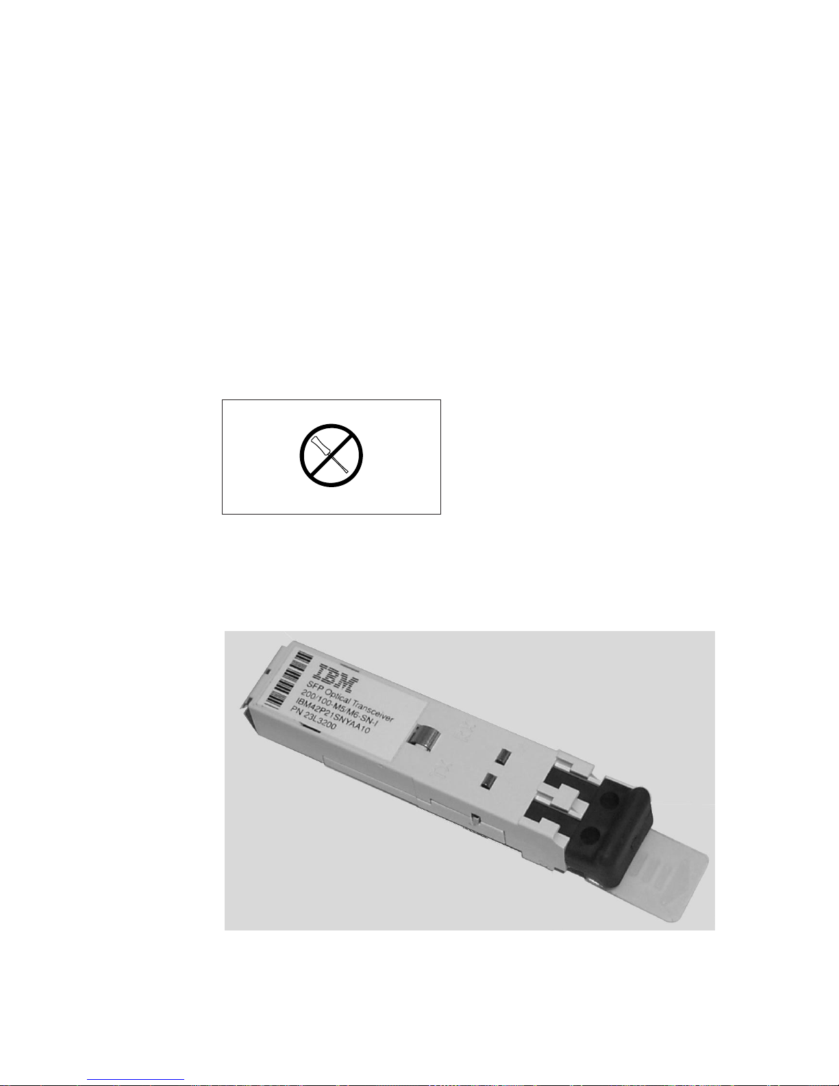
2. Verify that the small form-factor pluggable device (SFP) label shown in Figure 2
and Figure 3 on page xiii is installed on the 3534 Model F08.
Figure 2. SFP label (front view)
xii IBM TotalStorage SAN Switch: 3534 Model F08 Installation and User’s Guide
SJ000317
Page 15
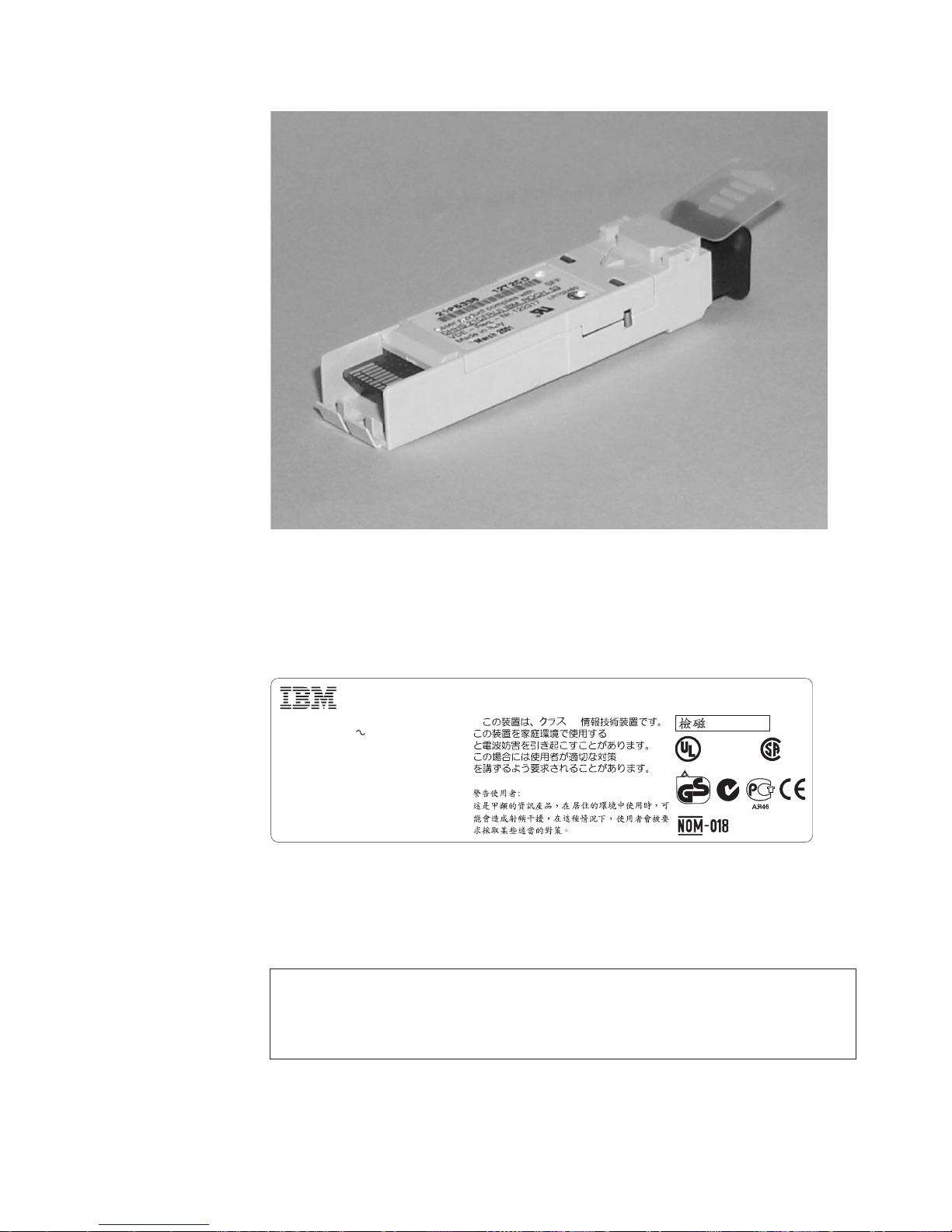
SJ000314
Figure 3. SFP label (back view)
3. Verify that the safety label shown in Figure 4 is installed on the 3534 Model
F08, and that the voltage specified on the label matches the voltage at the
power source.
Marca Registrada
Type: 3534
Model: F08
This machine is manufactured from new parts, or
new and used parts.
Assembled in the US of US and Non–US Components
for International Business Machines Corporation
Armonk, NY
Canada ICES/NMB-003 Class/Classe A
®
Figure 4. Safety label on the 3534 Model F08
Checking ac grounding
DANGER
An electrical outlet that is not correctly wired could place a hazardous
voltage on the metal parts of the system or the products that attach to the
system. It is the customer’s responsibility to ensure that the outlet is
correctly wired and grounded to prevent an electrical shock. (1)
Registered Trademark of
®
International Business Machines
Corporation IBM Canada Ltd.
Registered User
V
100 –240
A
1,0
kVA
0,2
47 631–
Hz
Ø
This device complies with part 15 of FCC rules. Operation is subject to the following two
conditions: (1) this device may not cause harmful interference, and (2) this device must
accept any interference received, including interference that may cause undesired operation.
A
VCCI-A
Product Safety
®
TÜV
Rheinland
3912E201
LISTED
I.T.E. 88Y4
E176896
geprüfte
Sicherheit
N2019
®
LR110877
P/N 18P4393
SJ000347
Safety and environmental notices xiii
Page 16

Environmental notices and statements
This section describes the environmental notices and statements.
Battery notice
CAUTION:
A lithium battery can cause fire, explosion, or a severe burn. Do not recharge,
disassemble, heat above 100°C (212°F), solder directly to the cell, incinerate,
or expose cell contents to water. Keep away from children. Replace only with
the part number specified for your system. Use of another battery may
present a risk of fire or explosion. The battery connector is polarized; do not
attempt to reverse the polarity. Dispose of the battery according to local
regulations. (3)
Laser safety
CAUTION:
In the United States use only GBIC units or Fibre-Optic products that
comply with FDA radiation performance standards, 21 CFR Subchapter J.
Internationally use only GBIC units or Fibre-Optic products that comply
with IEC standard 825-1. Optical products that do not comply with these
standards may produce light that is hazardous to the eyes. (4)
This unit might contain a single-mode or a multimode transceiver Class 1 laser
product. The transceiver complies with IEC 825-1 and FDA 21 CFR 1040.10 and
1040.11. The transceiver must be operated under the recommended operating
conditions.
This equipment contains Class 1 laser products, and complies with FDA radiation
Performance Standards, 21 CFR Subchapter J and the international laser safety
standard IEC 825-2.
Usage restrictions
The optical ports of the modules must be terminated with an optical connector or
with a dust plug.
Fire suppression systems
A fire suppression system is the responsibility of the customer. The customer’s own
insurance underwriter, local fire marshal, or a local building inspector, or both,
should be consulted in selecting a fire suppression system that provides the correct
level of coverage and protection. IBM designs and manufactures equipment to
internal and external standards that require certain environments for reliable
operation. Because IBM does not test any equipment for compatibility with fire
suppression systems, IBM does not make compatibility claims of any kind nor does
IBM provide recommendations on fire suppression systems.
SJ000338
Product recycling
This unit contains recyclable materials. These materials should be recycled where
processing sites are available and according to local regulations. In some areas,
xiv IBM TotalStorage SAN Switch: 3534 Model F08 Installation and User’s Guide
Page 17

IBM provides a product take-back program that ensures proper handling of the
product. Contact your IBM representative for more information.
Product disposal
This unit might contain batteries. Remove and discard these batteries, or recycle
them, according to local regulations.
Safety and environmental notices xv
Page 18

xvi IBM TotalStorage SAN Switch: 3534 Model F08 Installation and User’s Guide
Page 19

About this document
|
|
|
This document introduces the IBM®TotalStorage™SAN Switch 3534 Model F08,
hereafter referred to as the 3534 Model F08. It also describes how to plan for,
install, and use the 3534 Model F08.
Who should read this document
|
|
|
|
This document is intended for hardware service personnel who are responsible for
installing the 3534 Model F08 in a storage area network (SAN) fabric. It is also
intended for network administrators and system administrators whose
responsibilities include administration and management of a SAN.
Throughout this document, the term switch applies to any IBM 3534 switch, unless
the reference is to a specific model.
Additional information
This section contains the following information:
v A list of the documents in the 3534 Model F08 library
v A list of the related documents
v The available Web sites
v Instructions on how to get help
v Instructions on how to get software updates
v Information about how to send your comments
3534 Model F08 library
The following documents contain information related to this product:
|
|
v IBM TotalStorage SAN Switch 3534 Model F08 Installation and User’s Guide,
GC26-7559, (this book)
v IBM TotalStorage SAN Fibre Channel Switch 3534 Model F08 Translated Safety
Notices, GC26-7459
Related documents
You can find information that is related to the software that supports the 3534 Model
F08 in the following documents:
v Brocade Advanced Performance Monitoring User’s Guide
v Brocade Advanced Web Tools User’s Guide
v Brocade Advanced Zoning User’s Guide
v Brocade Diagnostic and System Error Message Reference
v Brocade Distributed Fabric User’s Guide
v Brocade Fabric Manager User’s Guide
v Brocade Fabric OS Procedures Guide
v Brocade Fabric OS Reference
v Brocade Fabric Watch User’s Guide
v Brocade ISL Trunking User’s Guide
v Brocade MIB Reference
v Brocade QuickLoop User’s Guide
|
v Brocade Secure Fabric OS User’s Guide
© Copyright IBM Corp. 2002, 2003 xvii
Page 20

Web sites
v Brocade SES User’s Guide
v Building and Scaling Brocade SAN Fabrics: Design and Best Practices Guide
When you use any of the Brocade documents, you will notice that the model
numbers reflect the original Brocade switches. Table 1 provides a product matrix for
you to use to correlate the Brocade model numbers to the IBM product and model
numbers.
Table 1. Brocade and IBM product and model number matrix
Brocade model number IBM product and model number
Silkworm 2010 3534 Model 1RU
Silkworm 2400 2109 Model S08
Silkworm 2800 2109 Model S16
Silkworm 3200 3534 Model F08
Silkworm 3800 2109 Model F16
Silkworm 3900 2109 Model F32
Silkworm 12000 2109 Model M12
For detailed information about models and firmware that the switch supports, see
the following Web site:
Getting help
|
|
|
|
|
|
www.ibm.com/storage/fcswitch/
For detailed information about fibre-channel standards, see the fibre-channel
Association Web site at:
www.fibrechannel.com/
For a directory of worldwide contact information, including technical support, see the
following Web site:
www.ibm.com/contact/
Contact your switch supplier for technical support on hardware, all product repairs,
and ordering of spare components. To report problems with the machine, call IBM
at the following locations:
v In Canada, call 1-800-465-6666.
v In the United States, call 1-800-IBM-SERV (426-7378).
You might be asked to present proof of purchase.
Be prepared to provide the following information to the support personnel:
v The switch serial number
v The switch worldwide name
v The topology configuration
v Any output from the supportShow Telnet command
v A detailed description of the problem
v Any troubleshooting steps that were already performed
xviii IBM TotalStorage SAN Switch: 3534 Model F08 Installation and User’s Guide
Page 21

Getting software updates
|
Contact your system vendor for software updates and maintenance releases.
For utility programs to facilitate loading firmware, sample Fabric Watch
configurations, and management information base (MIB) files for switch
management by simple network management protocol (SNMP), see the following
Web site:
www.storage.ibm.com/ibmsan/products/sanfabric.htm
How to send your comments
Your feedback is important to help us provide the highest quality of information. If
you have any comments about this document, you can submit them in one of the
following ways:
v E-mail
Submit your comments electronically to:
starpubs@us.ibm.com
Be sure to include the name and order number of the document and, if
applicable, the specific location of the text that you are commenting on, such as
a page number or table number.
v Mail or fax
Fill out the Readers’ Comments form (RCF) at the back of this document and
return it by mail or fax (1-800-426-6209) or give it to an IBM representative. If the
RCF has been removed, you can address your comments to:
International Business Machines Corporation
RCF Processing Department
Dept. M86/Bldg. 050-3
5600 Cottle Road
San Jose, CA 95193-0001
U.S.A.
About this document xix
Page 22

xx IBM TotalStorage SAN Switch: 3534 Model F08 Installation and User’s Guide
Page 23

Chapter 1. Introduction
|
This chapter introduces the 3534 Model F08 and includes the following information:
v Overview of the 3534 Model F08
v System components
v Hardware components
v Software components
v How to manage the 3534 Model F08
Overview of the 3534 Model F08
The 3534 Model F08 is an 8-port, dual-speed, auto-sensing Fibre Channel switch. It
supports link speeds up to 2 Gbps and is compatible and interoperable with the
current series of 2109 and 3534 switches. It can operate as the only switch in the
fabric or in a fabric that contains multiple switches.
The 3534 Model F08 has an air-cooled chassis that you can install either as a
stand-alone unit or mount in a 1U 48.26 cm (19 in.) rack. It includes the following
features:
v Eight optical ports, each with two light-emitting diodes (LEDs). One LED indicates
port status and the other LED indicates link speed.
v Automatic negotiation to the highest common speed of all devices that are
connected to a particular port. The ports are:
– Compatible with small form-factor pluggable media (SFP)
– Universal and self-configuring
– Capable of individually becoming a fabric enabled port (F_port), a fabric loop
enabled port (FL_port), or an expansion port (E_port)
v One serial port with an RS-232 connector
v One 10 Mbps or 100 Mbps Ethernet port with an RJ-45 connector and two LEDs.
One LED indicates port status and the other LED indicates link speed.
v Two switch status LEDs, one on the front panel and one on the back, which
indicate the overall status of the switch
v One power supply without an ac switch
v Five fan assemblies
Note: The 3534 Model F08 contains no serviceable parts except the SFPs. See
Chapter 4, “Replacing an SFP”, on page 31.
In addition, each 3534 Model F08 package includes:
v One 3.048 m (10 ft) RS-232 serial cable, which you can convert to an RJ-45
connector by removing the adapter on the end of the cable
v One 1.8288 m (6 ft) power cable
v Four rubber-mounting feet, which you can use if you are installing the switch as a
stand-alone unit
v One power-cable extender
v One rack-mount kit, which you can use if you are installing the switch in a rack.
See Table 3 on page 17 for a list of the parts included in the kit.
v One documentation CD-ROM
© Copyright IBM Corp. 2002, 2003 1
Page 24
v One copy of this book, the IBM TotalStorage SAN Switch 3534 Model F08
Installation and User’s Guide
See Appendix A, “Product specifications”, on page 33 for the 3534 Model F08
specifications.
System components
This section describes the front and back panels of the 3534 Model F08.
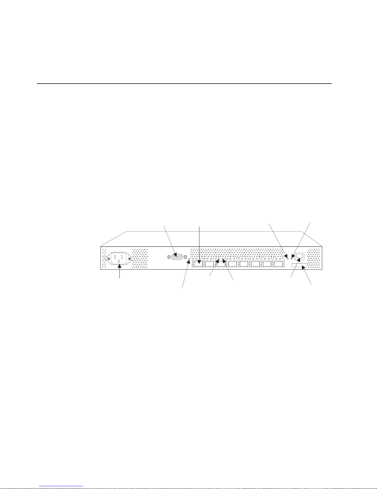
Front panel
Figure 5 shows the front panel of the 3534 Model F08. The front panel contains the
following components:
v Power connector
v IP address label
v Serial port
v Switch status LED
v Fiber optic ports and their corresponding LEDs
v Ethernet port and its corresponding LEDs
Serial Port
Power
Connector
Figure 5. Front panel of the 3534 Model F08
Switch
Status LED
Optical Port
(8)
Port Status
LED (8)
Ethernet
Link Speed
LED
Port Speed
LED (8)
Ethernet
Port
Ethernet
Status
LED
IP Address
Label
SJ000334
The ports on the front panel are color-coded in groups, indicating which ports can
be used in the same inter-switch link (ISL) Trunking group.
Note: ISL Trunking enables traffic to be distributed over the combined bandwidth of
up to four ISLs between two adjacent switches, while preserving in-order
delivery. It is managed through the software. For information about ISL
Trunking, see the Brocade ISL Trunking User’s Guide.
Back panel
Figure 6 on page 3 shows the back panel of the 3534 Model F08. The back panel
contains fans and the switch status LED.
2 IBM TotalStorage SAN Switch: 3534 Model F08 Installation and User’s Guide
Page 25

Figure 6. Back panel of the 3534 Model F08
Hardware components
Fan (5) Switch Status LED
SJ000336
CPU subsystem
The 3534 Model F08 system board is a single-board design with a highly integrated
CPU. The Intel
®
80960VH CPU is a RISC core processor and is the top choice for
this platform. It provides over 70% of the functionality for the digital section of the
system board. The system uses three types of memory devices: dynamic random
access memory (DRAM), Flash File, and Boot Flash. On the Fibre Channel section
of the system board, the following three components provide high-speed data
transfer:
v The Bloom ASICs
v The Serializer/Deserializer (SERDES)
v The SFP media. SFP media interfaces support SWL and LWL.
An Intel 80960VH CPU is used for management functions and switch initialization.
The CPU runs the Fabric OS and is responsible for switch initialization,
configuration, and management. Switching functionality is provided by the ASIC.
The following peripherals are also supported:
v An Ethernet port
v A serial port
v Three digital thermometers
v A real-time clock
v General input/output (I/O)
The CPU subsystem is a mixed voltage system that uses 1.8 V, 2.5 V, 3.3 V, and 5
V, depending on the device. The maximum board power consumption is 50 W.
Features
The 3534 Model F08 CPU subsystem includes the following features:
v A 80960VH-100 MHz CPU
v An SDRAM controller with parity check at 33 MHz
v A peripheral control interconnect (PCI) bus arbiter
v Main memory (SDRAM): 32 MB
v Flash memory: Dual 8 MB
v Boot flash memory: 512 bytes of 8-bit for system start
v 10BASE-T or 100BASE-T port for management connection with RJ45 connector
v One RS232 port with DB9 connector
Chapter 1. Introduction 3
Page 26

v Eight light-emitting diodes (LEDs) to indicate the status for each port
v Eight LEDs to indicate the link speed for each port
v One LED on the front panel to indicate the overall switch status
v One LED on the back panel to indicate the overall switch status
v Two LEDs for the Ethernet port to indicate the port status and link speed
information
v Three digital thermometers for temperature sensing
v One 3.3 V to 1.8 V dc/dc converter for the Bloom ASIC core supply
v One Bloom ASIC to support up to eight nonblocking ports
v Eight SERDES
v One real-time clock with a battery
Embedded processor
The embedded processor is an Intel 80960VH processor with a clock speed of 100
MHz. It contains the following components:
v A high-performance RISC processor core (compatible with the 2109 and 3534
series of switches)
v An integrated EDO memory controller (for DRAM, SRAM, read-only memory
(ROM), and Flash memory)
v A PCI bus interface
v A complex programmable logic device (CPLD) for SDRAM control
v Two direct memory access (DMA) channels
v An I2C interface
v General purpose I/O
You access system memory through the local bus. The external CPLD SDRAM
device provides SDRAM controller functionality at 33 MHz. It supports parity
checking to enhance the data integrity of the system. The CPU communicates with
the ASIC and the 10BASE-T or 100BASE-T Ethernet media access controller
(MAC) through the PCI interface. An external PCI bus arbiter enables the Ethernet
device to be a bus master.
You can also access the RS232 Universal Asynchronous Receiver Transmitter
(UART) serial port through the local bus. Other I/O peripherals, such as the
real-time clock, the LEDs, the three digital thermometers, and miscellaneous I/O are
handled by the I2C bus of the CPU. The CPU is the only I2C bus master in the
system. The RS232 port and drivers, Ethernet MAC/PHY, and LEDs are external
components to the CPU. An RJ45 connector provides Ethernet connection to
external systems. The DB9 RS232 is a ribbon-cable connection through the
on-board 10-pin header.
Bus operations
The interface between the embedded processor, the ASIC, and the 10BASE-T or
100BASE-T Ethernet MAC is implemented by using a PCI bus. All PCI devices on
the bus are PCI Revision 2.2 compliant. The PCI bus interface operates at 32-bit,
up to 33 MHz and has a worldwide even parity bit. A slave-only PCI interface is
provided by each ASIC to allow the processor to program various registers, routing
tables, and so on within the chip. An external PCI bus arbiter enables the Ethernet
device to be a bus master.
The local bus, a 32-bit multiplexed burst bus, provides the interface between the
system memory and the I/O. Because the integrated EDO memory controller on the
4 IBM TotalStorage SAN Switch: 3534 Model F08 Installation and User’s Guide
Page 27

CPU allows only direct control for DRAM, SRAM, ROM, and Flash memory, the
external CPLD controller is included to provide SDRAM controller functionality.
The I2C bus provides peripheral I/O control for the LEDs, the thermometers, and
general I/O functions. The 80960VH CPU serves as the master on the I2C bus.
The Bloom ASIC is an eight-port Fibre Channel switch controller. A proprietary
10-bit wide SSTL2 bus running at 106.25 MHz is used between the Bloom ASIC
and the SERDES.
Memory and memory architecture
The system design uses three types of memory devices:
v DRAM
v Flash File
v Boot Flash
One on-board SDRAM chips provides up to 32 MB for system memory. One
additional SDRAM chip provides data parity. The printed circuit board (PCB)
SDRAM footprint is designed to be compatible with 64 MB, 128 MB, and 256 MB
devices. An external CPLD device added to the local bus provides control functions
for the 80960VH processor.
The system provides 4 MB of on-board redundant Flash File memory for software
and data storage. The Boot Flash is an 8-bit Flash device socket that is used only
for system start. The Boot Flash device contains a block area for startup code
protection. The PLCC32 socket supports 3.3 V Boot Flash memory up to 512 KB.
As with the 2019 series of switches and the 3534 1RU switch, the 3534 Model F08
is based on a central memory architecture. In this scheme, a set of buffers in the
central memory is assigned to each port to be used for receipt of frames. As an
ASIC port receives and validates a frame, it stores the frame in one of its receive
buffers in the central memory and forwards a routing request (a Put message) to
the appropriate destination ports. When a destination port is capable of transmitting
the frame, it reads the frame contents from central memory and forwards the frame
to its transmit interface. It does not wait for the frame to be written in memory,
unless the port is busy. After it has removed an entry for a frame from its internal
transmit queue in preparation for transmitting a frame, the destination port sends a
transmission complete message (a Finish message) to the port that received the
frame. This allows the receiving port to reuse the buffer for subsequent frames
received.
Central memory is also incorporated into the ASIC. Frames received on the ports in
an ASIC are written into the portion of central memory.
The ASIC contains a RAM device plus data path crossbar logic that is used to
implement the central memory. Memory blocks are accessed in a time-sliced
fashion. The buffer pool can be split into 2112-byte buffers or into 312-byte
mini-buffers. If frames that need to be buffered are smaller than the maximum 2112
bytes, using mini-buffers effectively expands the buffer pool and increases the
efficiency of memory usage by providing more (but smaller) receive buffers.
Additionally, the Bloom ASIC provides a special memory interface (SMI). The SMI
provides the firmware with a mechanism to read and write frame contents to and
from the ASIC. It also supports higher throughput transfers. The SMI includes a set
of two buffers that are large enough for an entire maximum-sized frame to be
Chapter 1. Introduction 5
Page 28

transferred in a single operation. Additionally, because there are two buffers
available, the firmware can perform a read or write on a frame in one of the buffers
while the ASIC streams another frame into the other buffer.
ASIC
The ASIC provides eight Fibre Channel ports that you can use to connect to
external node ports (N_ports) (as an F_port) or external loop devices (as an
FL_port). You can connect one port (as an E_port) to another 3534 or 2109 series
switch. With the fabric upgrade, you might have up to eight E_ports.
Each port can operate at either 1.0625 Gbps or 2.125 Gbps link speeds. The ASIC
contains the Fibre Channel interface logic, message and buffer queuing logic,
receive buffer memory for the eight on-chip ports, and other support logic.
The Bloom ASIC is a PCI slave to the CPU. The ASIC interfaces through an
inter-chip 10-bit SSLT2 bus connection clocked at 106.25 MHz. An 8-channel
SERDES is used to support eight ports. The interface between ASIC and SERDES
is also a 10-bit SSTL2 bus running at 106.25 MHz. The SERDES converts the
10-bit wide parallel data from the SSTL2 bus into high-speed serial data for the
SFP media and vice versa. The SERDES supports single data rate (SDR) or double
data rate (DDR) transfer between the SERDES and the SFP media. Implementing
the SERDES external to the ASIC reduces the risk of silicon packaging as well as
the risk of running 2.125 Gbps signals on a board with a long trace length.
The SFP media interfaces with external devices and enables support for shortwave
laser and longwave laser. Two LEDs for each port provide port status and link
speed information.
Ports
Control Message Interface: The 3534 Model F08 Control Message Interface
(CMI) consists of a set of control signals that are used to pass hardware-level
messages between ports. Recipient ports use these control signals to inform
transmitting ports when a new frame needs to be added to the output queue of the
transmitter. Transmitting ports also use the CMI to inform recipient ports that a
frame transmission has been completed. A recipient port is free to reuse a receive
buffer when it receives notification that the frame has been transmitted. In the case
of multicast, multiple notifications are required to determine when a receive buffer is
freed.
The CMI interface for the ASIC is connected inside the ASIC. Each chip time slices
its output port to each possible destination chip in the switch. If it has a message to
send to a particular destination during the corresponding time slot, the chip uses the
time slot to send the message. Otherwise, the output port lines are driven to
indicate that no message is present.
The 3534 Model F08 supports the following port types:
v Optical ports
v Ethernet port
v Serial port
The ASIC in the 3534 Model F08 connects up to eight SFP modules. SFP devices
are encased in metal to ensure low emissions and high thermal management. They
are hot-swabble and use industry-standard local channel connectors. Each port
6 IBM TotalStorage SAN Switch: 3534 Model F08 Installation and User’s Guide
Page 29

provides ISL, loop, and fabric (E, F, and FL respectively) type connectivity that the
3534 Model F08 senses automatically. No adminsitration is necessary to identify the
port type.
Optical ports
For optical ports, the 3534 Model F08 uses SFP fiber-optic transceivers that convert
electrical signals to optical signals (and optical signals to electrical signals). Capable
of transmitting at both 1 and 2 Gbps speeds, each SFP fiber-optic transceiver
supports 850 nm SWL on multimode fiber-optic cable or 1310 nm LWL on
single-mode fiber-optic cable. These miniature optical transceivers provide high port
density and deliver twice the port density of standard removable gigabit interface
converter (GBIC) transceivers.
Ethernet port
The 3534 Model F08 provides a fully IEEE-compliant 10BASE-T or 100BASE-T
Ethernet port for switch management console interface. When a device is
connected to the port, both ends negotiate to determine the optimal speed. The
Ethernet port uses an RJ45 connector. There are two LEDs for the port. One LED
indicates transmit and receive activity and one LED indicates speed (10 Mbps or
100 Mbps). You can configure the Transmission Control Protocol/Internet Protocol
(TCP/IP) address for the port from the serial port.
Serial port
An RS232 serial port is provided on the 3534 Model F08. The serial port uses a
DB9 connector. The connector is a header pin block on the system board. The
parameters of the serial port are fixed at 9600 baud, 8 data bits, no parity, no
hardware flow control, 1 start, and 1 stop bit.
Enclosure
You use this connector to configure the internet protocol (IP) address and to recover
the factory default settings of the switch should Flash memory contents be lost. The
serial port connection should not be used to perform normal administration or
maintenance functions. Accessible functions are limited to connecting a terminal to
the port to reinitialize the switch defaults, which restores the switch to its factory
configuration. This is required to restore the switch passwords to a known state and
to allow you to set a specific switch IP address.
The 3534 Model F08 enclosure is designed for you to mount it in a 19-in. rack, with
a height of 1 RETMA unit, but you can use it in a tabletop configuration.
The 3534 Model F08 enclosure has forced-air cooling. The fans push the air from
the rear chassis intake through the enclosure and exhaust the air through venting
holes in the front panel. The SFP media is hot-swappable so that it can be removed
and replaced without interrupting the system power.
Other than the SFP replacement, the 3534 Model F08 has no user-serviceable
parts.
On the front of the unit, there are two port connections (an RS232 connection and
an RJ45 connection). The RJ45 connection provides a 10BASE-T or 100BASE-T
Ethernet port for a full system management console interface. The RS232
connection provides a serial port interface for setting the IP address of the switch
and for resetting the switch to factory defaults.
The fibre-optic cables, Ethernet cables, ac power input cables, and serial port
cables are located on the front of the switch.
Chapter 1. Introduction 7
Page 30

Power supply
The 3534 Model F08 power supply is universal and capable of functioning
worldwide without using voltage jumpers or switches. It meets IEC 61000-4-5 surge
voltage requirements and is auto-ranging in terms of accommodating input voltages
and line frequencies.
The power supply meets the following requirements:
Specification Value
Outlet Correctly wired and earth-grounded
Maximum output 75 watts
Maximum system power consumption 50 watts
Input voltage 90 – 264Vac
Input line frequency 47 – 63 Hz
Harmonic distortion Active power factor correction per
IEC1000-3-2
British thermal unit (BTU) rating 60 watts x 3.412 BTU/hr/watts = 204.72
BTU/hr
Inrush current 40 amps maximum, cold start at 25°C (77°F)
Input line protection Fused in hot line
LEDs
The 3534 Model F08 provides several LEDs to indicate status on the switch. Each
of the eight ports has two status indicators. The first LED for the port is a two-color
(green and yellow) LED, and indicates the status for the port. Green indicates
normal status, and yellow indicates an error. The second LED is a single-color
(green) LED and indicates the link speed for the port. Green indicates 2 Gbps. If
the green LED is not lit (dark), it indicates 1 Gbps.
A single-color (green) LED is located on the front of the switch and indicates system
power-on status. On the back of the switch, there is a two-color (green and yellow)
LED driven by an I2C I/O expander that indicates the mode of the unit. Green
indicates normal mode, and yellow indicates diagnostic mode. All LEDs are surface
mount components with on-board light pipe and are visible externally with full
chassis enclosure.
There are two LEDs for the Ethernet port located on the front panel. One LED
indicates the transmit and receive activity, and one LED indicates speed (10 Mbps
or 100 Mbps).
Software components
The 3534 Model F08 is supported by the Fabric OS version 3.1 or later.
|
|
|
|
Fabric OS is implemented in firmware and manages the operation of the 3534
Model F08. The switch firmware is designed to make a 3534 Model F08 easy to
install and use while retaining the flexibility needed to accommodate your
requirements. The Fabric OS is made up of two major software components:
v Firmware that initializes and manages the switch hardware
v Diagnostics that perform component self-testing algorithms for fault isolation
during the manufacturing process and in your installation
8 IBM TotalStorage SAN Switch: 3534 Model F08 Installation and User’s Guide
Page 31

|
|
|
|
|
|
You can view the internal firmware as a set of embedded applications that run on
top of a proprietary real-time operating system that consists of the following
components:
v Name server
v Alias server
v SNMP agent
Additionally, host-based software includes the drivers, utilities, and applications that
use the switch. Obtain these components from your system vendor or Fibre
Channel component supplier.
For more information, see the Brocade Fabric OS Procedures Guide and the
Brocade Fabric OS Reference.
Features and functions
|
|
The software that supports the 3534 Model F08 includes the following features and
functions.
Secure Fabric OS
The Fabric OS supports the Secure Fabric OS, which includes security
features that you can use with other security tools to implement increased
security in your SAN. For more information, see the Brocade Secure Fabric
OS User’s Guide.
Web Tools
Web Tools provide a graphical user interface (GUI) that enables an
administrator to monitor and manage entire fabrics and individual switches
and ports from a standard workstation. For more information, see the
Brocade Advanced Web Tools User’s Guide.
Auto-sensing speed negotiation
The 3534 Model F08 ASIC supports link operation at either 2 Gbps or 1
Gbps. Auto-sensing negotiation allows easy configuration.
Optionally licensed features
|
|
Version 3.1 or later of the Fabric OS have the following optionally licensed features
that enhance the Fibre Channel switch.
Full fabric switch upgrade
The full fabric switch upgrade feature provides connectivity of up to eight
other switches, Advanced Zoning, and Fabric Watch. For more information,
see the Brocade Advanced Zoning User’s Guide and the Brocade Fabric
Watch User’s Guide.
Performance Bundle (Performance Monitoring and ISL Trunking)
Advanced Performance Monitoring is a comprehensive tool for monitoring
the performance of networked storage resources. For more information, see
the Brocade Advanced Performance Monitoring User’s Guide.
QuickLoop (Request price quote)
ISL Trunking connects up to four ISLs between two switches through an
expansion port (E_port) to merge logically into one link. For more
information, see the Brocade ISL Trunking User’s Guide.
Chapter 1. Introduction 9
Page 32

QuickLoop enables servers with host bus adapters that use Fibre Channel
Arbitrated Loop private loops to communicate with Fibre Channel storage
devices through IBM TotalStorage SAN switches. For more information, see
the Brocade QuickLoop User’s Guide.
Secure feature
The Secure feature provides customizable security restrictions through local
and remote management channels on a switch fabric. For more information,
see the Brocade Secure Fabric OS User’s Guide.
Fabric Manager
Fabric Manager provides a GUI that allows the administrator to monitor and
manage a fabric from a standard workstation. For more information, see the
Brocade Fabric Manager User’s Guide.
Extended fabrics
Extended fabrics activation extends SAN fabrics beyond the Fibre Channel
standard 10 km, which enables high performance applications over
extended distances for storage consolidation, data protection, disaster
tolerance, and data sharing.
Remote switch
Remote switch activation extends the distance of the SAN fabric by
enabling two Fibre Channel switches to interconnect over an asychronous
transfer mode (ATM) wide area network (WAN).
Note: To activate these features, go to the following Web site:
Switch initialization
When you start or restart the switch, the following operations are performed:
1. Early power-on self test (POST) diagnostics are run. POST is run before
VxWorks is running.
2. VxWorks is initialized.
3. The hardware is initialized. The system is reset, the internal addresses are
assigned to Loom chips, the Ethernet port is initialized, the serial port is
initialized, and the front panel is initialized.
4. A full POST is run.
5. The links are initialized. Receiver and transmitter negotiation is run to bring the
connected ports online.
6. A fabric exploration is run. This determines whether any ports are connected to
other switches. If so, it determines the principal switch.
7. Addresses are assigned. After the principal switch is identified, port addresses
are assigned. Each 3534 Model F08 tries to keep the same addresses that it
used previously. Previous addresses are stored in the configuration Flash
memory.
8. The routing table is constructed. After the addresses are assigned, the unicast
routing tables are constructed.
9. Normal node port or node loop port (Nx_port) operation is enabled.
www.ibm.com/storage/key/
10 IBM TotalStorage SAN Switch: 3534 Model F08 Installation and User’s Guide
Page 33

Routing
The embedded processor maintains two routing tables, one for unicast and one for
multicast. The unicast routing tables are constructed during fabric initialization. The
multicast tables are initially empty, except for broadcast. After the tables have been
constructed, they are loaded into each ASIC.
The unicast tables change if ports or links come online or go offline, or if some
other topology changes occur. When new paths become available, the embedded
processor can change some routes in order to share the traffic load. The multicast
tables change as ports register with the alias server to create, join, or leave a
multicast group. Each time a table changes, it must be reloaded into the ASICs.
Service functions
The ASIC interrupts the embedded processor when a frame arrives that has an
error (for example, incorrect source ID), when a frame times out, or when a frame
arrives for a destination that is not in its routing tables. In the latter case, the frame
might be addressed to an illegal destination ID, or it might be addressed to one of
the service functions that the embedded processor provides, such as SNMP, name
server, or alias server.
SNMP
Simple Network Management Protocol (SNMP) allows network devices to be
monitored, controlled, and configured remotely from a network management station
running a network manager program.
SNMP agent code in the network device allows management by transferring data
that is specified by a management information base (MIB).
The 3534 Model F08 agent supports the following functions:
v SNMPv1 manager
v Command-line utilities to access and command the agent
v MIB-II system group, interface group, and SNMP group
v Fabric-element MIB
v IBM-specific MIBs
v Standard generic traps
v IBM-specific traps
Diagnostics
The 3534 Model F08 supports a set of POSTs, as well as tests that you can run by
using Telnet commands. These diagnostics are used during the manufacturing
process as well as for fault isolation of the product in your installation.
For more information, see the Brocade Diagnostic and System Error Message
Reference.
Diagnostic environment
Most diagnostics are written to run in the VxWorks environment. However, as
VxWorks does not run without a working SDRAM, a SDRAM/boot EEPROM test is
run as part of the pre-VxWorks startup code to verify that the basic
processor-connected memories are functioning properly.
Chapter 1. Introduction 11
Page 34

Hardware support
Loop-back paths for frame traffic are provided in the hardware for diagnostic
purposes. A loop-back path within the ASIC, at the final stages of the Fibre Channel
interface, can be used to verify that the internal Fibre Channel port logic is
functioning properly, as well as paths between the interface and the central memory.
Additionally, the SERIALLINK macro within the ASIC includes a serial data
loop-back function that can be enabled through a register in the corresponding
ASIC.
Diagnostics are provided to allow traffic to be circulated between two switch ports
that are connected with an external cable. This allows the diagnostics to verify the
integrity of the final stage of the SERDES interface, as well as the media interface
module.
Diagnostic coverage
The POST and diagnostic commands concentrate on the Fibre Channel ports and
verify switch functionality of the 3534 Model F08.
Interoperability
This section includes information about interoperability.
Switch interoperability
The 3534 Model F08 supports both 1 Gbps and 2 Gbps transmit and receive rates
with auto-negotiation. The actual data signaling rate that is used on a port is
automatically sensed and is set to the rate that is supported by a device or devices
that are attached to the port. The 3534 Model F08 has been tested and is compliant
with the current FC standards. The 3534 Model F08 is compatible with most
current-generation switches N_ports, NL_ports, and E_ports, as well as host
adapters, Redundant Array of Independent Disks (RAIDs) storage devices, hubs,
and Fibre-SCSI bridge devices, including the 3534 and 2109 series of switches.
Implementation in existing environments
Because the 3534 Model F08 has a compatible 1 Gbps auto-negotiated signaling
rate on each port, you can use it as a replacement for current 3534 and 2109
series switches. As newer technology is added to existing systems that support
2 Gbps signaling, the ports can accept these devices and interoperate with existing
1 Gbps devices. If the 3534 Model F08 is connected to a third-party device but is
unable to negotiate the signaling rate, the 3534 Model F08 allows you to manually
set the speed of each port through the management interfaces.
Heterogeneous interswitch operations
Fabric OS version 3.1 or later supports interoperability for the following functions:
v Basic switch functions
– Link initialization
– Principal switch selection
– Routing Fibre Channel shortest path first (FSPF)
v Basic services
– Simple name service
– State change notification
– WWN zoning (typically referred to as soft zoning or name server zoning)
12 IBM TotalStorage SAN Switch: 3534 Model F08 Installation and User’s Guide
Page 35

The following facilities are switch-based facilities and will continue to function on
any 3534 switch:
v SNMP facilities
v Simple QuickLoops with no zoning
v Translative mode (private target support on fabrics)
v Trunking (only functions between two IBM switches)
v Enhanced performance metrics
The following facilities are IBM value-added facilities that are not supported in a
multi-vendor fabric. Use of these facilities causes the Fabric to segment.
v QuickLoop zones
v QuickLoop Fabric assist mode
v Port, protocol, or LUN zoning
IBM is not aware of any areas of noncompliance with any ratified standards at this
time.
Host bus adapter interoperability
For a list of host bus adapters (HBAs) that have been tested and approved for use
with the 3534 Model F08, go to the following Web site:
www.storage.ibm.com/ibmsan/products/2109/san_switch_solu.html
Operating system support
Fabric OS versions 2.x and 3.x have no specific OS dependencies. The Fabric OS
in the switches allows for any Fibre Channel-compliant device to attach to the
switches as long as it conforms to the standards for device login, name service, and
related Fibre Channel features. Regardless of the operating environment, proper
interface to the fabric requires a Fibre Channel HBA with a standards-compliant
driver.
Reliability
The 3534 Model F08 provides the following features to ensure reliability:
v POST
v Error detection and fault isolation (internal and external CRC checking, parity
checking, checksum, and illegal address checking)
v Continuous monitoring of environmental components (fan status and
temperature)
v DC power in proper range monitoring
v Low component count
Because buffering is integrated into the ASICs in the 3534 Model F08, you do not
need external SRAM chips on the system board.
The 3534 Model F08 utilizes a highly integrated 80960VH processor that
incorporates a memory controller, PCI bus arbiter, and I2C controller in the
processor chip, reducing the parts count for the processor functions. Because a
single system board contains all circuitry, the 3534 Model F08 requires no
interboard connections.
Chapter 1. Introduction 13
Page 36

How to manage the 3534 Model F08
For system debugging and performance analysis, you can manage the 3534 Model
F08 using either the in-band or the out-of-band management method. In-band uses
Fibre Channel protocol and out-of-band connects to the Ethernet port. You can
monitor the following attributes:
v Fabric topology
v Port status
v Physical status
Note: The switch automatically performs power-on self-test (POST) diagnostics
each time you turn it on and records any detected errors in the error log. For
more information about POST, see “Interpreting POST” on page 28.
Table 2 shows the management interfaces that are compatible with the 3534 Model
F08 and whether you can use these interfaces in-band, out-of-band, or both.
Table 2. Management interfaces compatible with the 3534 Model F08
Management interface In-band Out-of-band
Command-line interface
through a Telnet connection
Web Tools X X
Standard simple network
management protocol
(SNMP) applications
SCSI Enclosure Services
(SES)
XX
XX
X
For more information about these management interfaces, see the following
documents:
v Brocade Advanced Performance Monitoring User’s Guide
v Brocade Advanced Web Tools User’s Guide
v Brocade Advanced Zoning User’s Guide
v Brocade Diagnostic and System Error Message Reference
v Brocade Distributed Fabric User’s Guide
v Brocade Fabric Manager User’s Guide
v Brocade Fabric OS Procedures Guide
v Brocade Fabric OS Reference
v Brocade Fabric Watch User’s Guide
v Brocade ISL Trunking User’s Guide
v Brocade MIB Reference
v Building and Scaling Brocade SAN Fabrics: Design and Best Practices Guide
14 IBM TotalStorage SAN Switch: 3534 Model F08 Installation and User’s Guide
Page 37

Chapter 2. Installing and configuring the 3534 Model F08
You can install the 3534 Model F08 as a stand-alone unit or in a rack that meets
Electronic Industries Association (EIA) standards.
This chapter describes how to install and configure the 3534 Model F08 and
includes the following information:
v Installation and safety considerations
v Installing the 3534 Model F08 as a stand-alone unit
v Installing the 3534 Model F08 in an EIA rack
v Configuring, connecting, and accessing the 3534 Model F08
For information about the features of the 3534 Model F08 and what is included in
each 3534 Model F08 package, see “Overview of the 3534 Model F08” on page 1.
Installation and safety considerations
You must follow these guidelines when you install the switch:
v Verify that the supply circuit, line fusing, and wire size that will be used are
adequate according to the electrical rating on the switch nameplate.
v The switch is designed for an internet protocol (IT) power system with
phase-to-phase 230 V. The power supply might still be energized, even if internal
power supply over current protection devices have opened.
DANGER
When powering the unit with a line-to-line connection greater than 200 V
ac, a potential shock hazard can arise during a fault condition.
Therefore, double-pole protection is required. (5)
v Ensure the ambient air temperature does not exceed 40°C (104°F). This is
particularly important if the switch is to be installed in a closed or multirack
assembly.
v Ensure the volume of air flow available to the switch is at least 300 cubic feet per
minute, and that the front and rear air vents are not blocked.
If you are installing the switch in a rack:
v Ensure the ambient air temperature does not exceed 40°C (104°F). This is
particularly important if the switch is to be installed in a closed or multirack
assembly.
v Ensure the volume of air flow available to the switch is at least 300 cubic feet per
minute, and that the front and rear air vents are not blocked.
v The switch requires a rack space that is 1 unit high, 48.26 cm (19 in.) wide, and
60.96 cm (24 in.) deep.
v Verify that all equipment installed in the rack has a reliable branch circuit ground
connection. Do not rely on a connection to a branch circuit, such as a power
strip.
v Verify that the additional weight of the switch does not unbalance the rack or
exceed the weight limits of the rack.
v Secure the rack to ensure stability in the event of an earthquake.
© Copyright IBM Corp. 2002, 2003 15
Page 38

Installing the 3534 Model F08 as a stand-alone unit
Follow this procedure to install the switch as a stand-alone unit on a flat surface.
Time required
Approximately 10 minutes
Installation instructions
Complete the following steps to install the switch as a stand-alone unit:
1. Unpack the 3534 Model F08. Verify that all ordered items are present.
2. Turn the switch upside down. Lay it on its top.
3. Apply the adhesive rubber feet.
Attention: Install the rubber feet on the switch to minimize the chance of the
switch sliding off the supporting surface.
a. Clean the four depressions on the chassis bottom to ensure that they are
free of dust.
b. Place one rubber foot in each depression with the adhesive side against the
chassis.
c. Press the rubber feet firmly into place.
4. Return the switch to its normal upright position. Place it on a sturdy flat surface.
5. When you are ready to supply power to the switch, connect the power cable to
the 3534 Model F08 power supply and to a power outlet. (The power supply
does not have an ac switch.)
The 3534 Model F08 automatically runs a POST each time power is supplied to
it.
DANGER
An electrical outlet that is not correctly wired could place a hazardous
voltage on metal parts of the system or the products that attach to the
system. It is the customer’s responsibility to ensure that the outlet is
correctly wired and grounded to prevent an electrical shock. (1)
Attention: Ensure that the power cable is routed so that it is not pinched or
exposed to stress.
Note: Do not connect the switch to the network until the internet protocol (IP)
Installing the 3534 Model F08 in an EIA rack
Follow this procedure to install the 3534 Model F08 in a rack that meets EIA
standards.
CAUTION:
The 3534 Model F08 switch is designed to be installed by the customer, and is
certified as “customer setup”. Make sure that the system or rack into which
the switch will be installed is also designed and certified for customer setup;
if it is not, then the switch must be installed by a CE. (1)
Time required
Approximately 30 minutes
16 IBM TotalStorage SAN Switch: 3534 Model F08 Installation and User’s Guide
address is correctly set. For more information, see “Configuring,
connecting, and accessing the 3534 Model F08” on page 21.
Page 39

Items required
You will require the following items to install the 3534 Model F08 in an EIA rack:
v Straight slot screwdriver
v Rack space: 1 rack unit high, 48.26 cm (19 in.) wide, and 60.96 cm (24 in.) deep
v Rack mount kit; see Table 3 for a list of the parts that are included in the kit
v Power cable, provided with the switch
v Power outlet
Attention: Use the exact screws specified in the procedure for use with the
switch chassis. Using screws longer than 3/16 in. can damage the switch. The
different types of screws are listed in Table 3.
Note: Firmly tighten all the screws that this procedure uses.
Installation instructions
This section describes the basic procedure of installing the 3534 Model F08 in an
EIA rack, and then provides detailed steps.
Note: To ensure that the switch is adequately cooled, install it with the port side
(the side with the SFP) facing the aisle where exhaust air is released
(usually referred to as the service aisle). This prevents the fans from pulling
in heated exhaust air.
Basic procedure
The basic rack-mount installation procedure consists of the following four steps:
1. Mount the moving slide and the lock mounting ears to the switch.
2. Mount the fixed portion of the slide in the rack.
3. Insert the switch and move a portion of the slide into the fixed portion on the
rack.
4. Lock the switch in the rack using the mounting ears installed in step 1.
Detailed steps
Note: These steps use parts that are included in the 3534 Model F08 rack mount
kit. These parts are listed in Table 7. The installation procedure
cross-references the items in this table. Be sure that you use the referenced
parts when you perform each step.
To complete the rack-mount installation procedure, follow these detailed steps:
1. Unpack the 3534 Model F08. Verify that all ordered items and parts are present.
See Table 3 for a list of parts and the quantities that are supplied in each rack
mount kit.
Table 3. Parts supplied with the rack mount kit
Item Description Quantity
1 Rack mount slide (inner and outer slide) 2
2 Right rack mount bracket (optional bracket for the front of
the switch)
3 Left rack mount bracket (optional bracket for the front of
the switch)
4 Rack mounting bracket (3-hole) 4
1
1
Chapter 2. Installing and configuring the 3534 Model F08 17
Page 40

Table 3. Parts supplied with the rack mount kit (continued)
Item Description Quantity
5 Nut clip, M5 11
6 Screw, 8-32 x 3/16 in., zinc 11
7 Screw, M5 x 12 11
8 Bracket to slide rack kit (contains items 9 - 12) 1
9 Screw, 8-32 x 3/8 in., zinc 5
10 Washer, flat, No. 8 5
11 Washer, lock, No. 8 5
12 Nut, hex, 8-32 5
Note: Because this rack mount kit is distributed with various switches, you might end up
with extra parts that are not needed for the installation of your switch into your rack
assembly.
2. Separate the inner and outer slides.
a. Open one of the slides until the lock engages.
b. Press the lock release lever, and remove the inner rail from the outer rail, as
shown in Figure 7.
1
SJ000046
Figure 7. Moving slide
c. Repeat steps 2a - 2b for the other rail.
®
Note: For racks with flush-mount doors such as the 9306 Netfinity
racks, you
can eliminate the installation of the ears. Instead, use the rack-mount
slides by attaching the 3534 Model F08 to the set of mounting holes,
which are offset 2.62 cm (3 in.) into the rack.
3. Install the inner (smaller) slide on the 3534 Model F08 chassis.
a. Position the flat side of the inner rail along one side of the switch, aligning
the holes in the rail with the threaded holes in the side of the switch chassis.
The chamfered end of the inner rail should face toward the rear of the
switch (away from the ports) as shown in Figure 8 on page 19.
b. Attach the inner rail using two of the 8-32 x 3/16 in. zinc screws 6.
Attention: Using screws longer than 3/16 in. can damage the switch.
18 IBM TotalStorage SAN Switch: 3534 Model F08 Installation and User’s Guide
Page 41

c. Repeat steps 3a on page 18 - 3b on page 18 for the second inner rail on the
other side of the switch chassis.
4. Optional step: If desired, install the right rack mount bracket 2 and the left
rack mount bracket 3 on the switch chassis. These brackets secure the switch
to the rack as shown in Figure 8.
Offset holes for
9306 Netfinity racks
6
3
Front
Figure 8. Mounting the moving portion of the slide and the mounting brackets to the switch
1
Sj000348
a. Position the left rack mount bracket at the left front corner of the switch
chassis, so that the two holes in the bracket align with the two threaded
holes in the switch chassis.
b. Attach the bracket using two of the 8-32 x 3/16 in. zinc screws 6.
Attention: Using screws longer than 3/16 in. can damage the switch.
c. Repeat steps 4a - 4b for the right rack mount bracket on the right front
corner of the switch chassis.
5. Attach all four of the 3-hole rack mounting brackets 4 as shown in Figure 9 on
page 20.
Chapter 2. Installing and configuring the 3534 Model F08 19
Page 42

4
12
11
10
1
5
9
4
3
Figure 9. Mounting the fixed portion of the rail and the locking ears to the rack
SJ000048
a. Position a 3-hole bracket 4 at the end of one of the outer slides.
b. Attach the bracket using the 8-32 x 3/8 in. zinc screws 9. Make sure that
the screw heads are inside the slides.
c. Place one of each of the following items on the outer end of the screw in the
order listed:
1) Washer flat No. 8 10
2) Washer, lock No. 8 11
3) Nut, hex, 8-32 12
d. Repeat steps 5a - 5b for the three remaining rail ends.
6. Install the outer (larger) slides in the rack, as shown in Figure 9.
a. At the desired height, install the five M5 nut clips 5; put three in the front
of the rack and two in the back. The middle clip in the front of the rack is for
the locking ears.
b. Attach the slides using four M5 x 12 screws 7.
c. Repeat steps 6a - 6b for the other rail.
7. Install the switch in the rack.
a. Position the switch in front of the rack. Insert it into the rack by sliding the
inner slides on the switch into the outer slides on the rack. See Figure 10 on
page 21.
20 IBM TotalStorage SAN Switch: 3534 Model F08 Installation and User’s Guide
Page 43

SJ000049
Figure 10. Inserting slides into the rack rails
b. Verify the alignment of the slides by sliding the switch in and out of the rack.
Any difficulty moving the switch indicates lateral stress or misalignment. If
this occurs, adjust the slide positions until the movement is smooth.
8. Optional step: If the right rack mount bracket and the left rack mount bracket
were installed on the front corners of the switch (see step 4 on page 19), attach
both brackets to the cabinet rack using M5 x 12 screws 7.
DANGER
An electrical outlet that is not correctly wired could place a hazardous
voltage on metal parts of the system or the products that attach to the
system. It is the customer’s responsibility to ensure that the outlet is
correctly wired and grounded to prevent an electrical shock. (1)
9. When you are ready to supply power to the switch, connect the power cable to
the 3534 Model F08 power supply and to a power outlet. The power supply
does not have an ac switch.
The 3534 Model F08 automatically runs a POST each time power is supplied to
it.
Attention: Ensure that the power cable is routed so that it is not pinched or
exposed to stress when the switch is moved on the slides.
Note: Do not connect the switch to the network until the IP address is correctly
Configuring, connecting, and accessing the 3534 Model F08
Follow this procedure to configure, connect, and access the 3534 Model F08 for
use in a network fabric.
Time required
Approximately 15 minutes
set or the default IP address is verified as not conflicting with the existing
IP addresses in the same network. For more information, see
“Configuring, connecting, and accessing the 3534 Model F08”.
Chapter 2. Installing and configuring the 3534 Model F08 21
Page 44

Items required
You will need the following items to configure, connect, and access the 3534 Model
F08:
v A 3534 Model F08 that is installed and connected to a power source
v A workstation that has a terminal emulator application (such as HyperTerminal)
v A serial cable that is provided with the switch, for connecting the switch to the
workstation
v An unassigned IP address
v An Ethernet cable for connecting the switch to the workstation or to a network
containing the workstation
v Short wavelength (SWL) or long wavelength (LWL) SFPs and fiber optic cables,
as required
Configuring the switch
To configure the 3534 Model F08, replace the factory IP address and related
information with the IP information that is provided by your network administrator.
Perform the following steps:
1. Remove the shipping plug from the serial port. Insert the serial cable that is
provided with the 3534 Model F08.
2. Connect the other end of the serial cable to an RS-232 serial port on the
workstation. If no RS-232 serial port is available on the workstation, you can
remove the adapter that is on the end of the serial cable. This enables you to
use the RJ-45 connector to create a serial connection.
3. Verify that the switch is on and that a POST has completed.
4. Disable any serial communication programs that are running on the
workstation.
5. Open a terminal emulator application, such as HyperTerminal on a PC or
TERM in a UNIX
2000, or NT environment, use the configuration parameters shown in Table 4.
®
environment. Configure the switch. For a Windows®95, 98,
Table 4. Configuration parameters
Parameter Value
Bits per second 9600
Databits 8
Parity None
Stop bits 1
Flow control None
In a UNIX environment, type the following command:
tip /dev/ttyb -9600
6. From the terminal emulator application, log on to the switch through the serial
connection. The default administrative logon is admin, and the default
password is password.
7. Type the following command:
ipAddrSet
8. Type the appropriate information at the following prompts:
Note: The variables within brackets represent the default settings that your
information replaces.
22 IBM TotalStorage SAN Switch: 3534 Model F08 Installation and User’s Guide
Page 45

v Type the new Ethernet IP address:
Ethernet IP Address [10.77.77.77]:
v Type the new Ethernet subnetmask:
Ethernet Subnetmask [0.0.0.0]:
v Type the new Fibre Channel IP address, if desired:
Fibre Channel IP Address [none]:
v Type the new Fibre Channel subnetmask, if desired:
Fibre Channel Subnetmask [none]:
v Type the new gateway address:
Gateway Address [172.17.1.1]:
v Type y to set the IP address now:
Set IP address now? [y = set now, n = next reboot]:
9. Type the following command to verify that the address was set correctly:
ipAddrShow
10. After you verify the IP address, remove the serial cable and replace the
shipping plug in the serial port.
Note: Use the serial port only during the initial setting of the IP address and
for service purposes. Do not use the serial port during normal switch
operation or for regular maintenance.
11. Record the IP address for future reference.
Connecting and accessing the switch
Complete the following steps to connect the switch to the workstation using an
Ethernet cable (this can be a direct connection or through a network), and to
access the switch:
1. Remove the shipping plug from the Ethernet port.
2. Insert one end of an Ethernet cable in the Ethernet port.
3. Connect the other end of the Ethernet cable to the workstation or to an Ethernet
network that contains the workstation.
Note: You can now access the switch remotely, using Telnet or Web Tools.
Ensure that the switch is not being modified simultaneously from any
other connections during the remaining steps.
4. Log on to the switch using Telnet. The default administrative logon is admin, and
the default password is password.
5. Modify the domain IDs if desired.
Note: The default domain ID is 1. If the domain ID is already in use when the
switch is connected to the fabric, the domain ID for the new switch is
automatically reset to a unique value. You can determine the domain IDs
that are currently in use by issuing the Telnet fabricShow command. For
more information about Telnet commands, see the Brocade Fabric OS
Reference.
a. Type the following command to disable the switch:
switchDisable
b. Type the following command:
configure
c. Type y at the Fabric parameters prompt. For example:
Chapter 2. Installing and configuring the 3534 Model F08 23
Page 46

Fabric parameters (yes, y, no, n): [no] y
d. Type a unique domain ID (such as the domain ID used by the previous
switch, if still available) at the Domain prompt. For example:
Domain: (1..239) [1] 3
e. Complete the remaining prompts, or press CTRL+D to accept the remaining
settings without completing all the prompts.
f. Type the following command to enable the switch:
switchEnable
6. Optional step: Specify any custom status policies for the fabric.
a. Type the following command at the prompt:
switchStatusPolicySet
b. Specify the desired status policies. To completely deactivate the alarm for a
particular condition, type 0 at the prompt for that condition.
7. Add SFPs and fiber optic cables to the ports as required.
Note: The ports and cables that are used in trunking groups must meet specific
requirements. For information about these requirements, see the Brocade
ISL Trunking User’s Guide.
a. Remove the shipping plug from the ports to be used.
b. Position the SFP so that the key (the tab near the cable end of the SFP) is
on top. Insert the SFP into the port until it is firmly seated and the latching
mechanism makes a clicking sound.
Note: The SFP is keyed so that it can only be correctly inserted into the
port. If the module does not slide in easily, try turning it over. Do not
force the module.
c. Connect the fiber-optic cables to the SFPs as appropriate to the fabric
topology. Position each cable so that the key (the ridge on one side of the
cable connector) is aligned with the slot in the SFP. Insert the cable into the
SFP until it is firmly seated, and the latching mechanism makes a clicking
sound.
Note: The cable is keyed so that it can only be correctly inserted into the
SFP. If the cable does not slide in easily, try turning it over. Do not
force the cable.
8. Verify the correct operation of the 3534 Model F08. Type the following command
at the Telnet prompt:
switchShow
This command provides information about the status of the switch and the ports.
For more information about this and other commands, see the Brocade Fabric
OS Reference.
Note: Back up the configuration after any initial changes and periodically
thereafter. This ensures that a complete configuration is available if you
need to install a replacement switch. For information about backing up
the configuration, see the Brocade Fabric OS Procedures Guide.
24 IBM TotalStorage SAN Switch: 3534 Model F08 Installation and User’s Guide
Page 47

Chapter 3. Operating the 3534 Model F08
This chapter describes how to operate the 3534 Model F08 and includes the
following information:
v Turning the 3534 Model F08 on and off
v Interpreting LED activity
v Interpreting POST
v Running diagnostic tests
Turning the 3534 Model F08 on and off
To turn on the 3534 Model F08, plug it into a power outlet. The power supply does
not have an ac switch. To turn the switch off, unplug it from the power outlet.
Note: Unplugging the switch triggers a system reset. When the switch is plugged
in, all devices are returned to the initial state and the switch runs a POST.
For information about the POST, see “Interpreting POST” on page 28.
Interpreting LED activity
You can determine system activity and status by monitoring the activity of the LEDs
on the switch.
Note: The LEDs might flash yellow during diagnostic tests and green, orange, or
yellow during a POST. This is normal. This does not indicate that there is a
problem unless the LEDs do not return to a normal pattern after the POST is
complete.
The 3534 Model F08 has the following LEDs:
Port Status LED
These LEDs indicate the status of each port. There are eight port status
LEDs that are located above and to the left of each port on the front panel.
Port Speed LED
These LEDs indicate the speed of each port. There are eight port speed
LEDs that are located above and to the right of each port on the front
panel.
Switch Status LED
These LEDs indicate whether the switch is on and has successfully started.
There are two switch status LEDs, one on the front panel and one on the
back.
Ethernet port LED
These LEDs indicate the speed and status of the Ethernet link. There are
two Ethernet port LEDs that are located to the left of the Ethernet port on
the right side of the front panel.
LEDs on the front panel
Figure 11 on page 26 shows the front panel with the different LEDs identified.
© Copyright IBM Corp. 2002, 2003 25
Page 48

Ethernet
Link Speed
LED
Ethernet
Status
LED
Switch
Status LED
Figure 11. Front panel LEDs
Port Status
LED (8)
Port Speed
LED (8)
Table 5 lists the front panel LEDs and describes the following items:
v The name of the LED
v The location of the LED
v The color of each LED
v The status of the switch that is associated with each LED color
v The action that you can take in response to that status
Table 5. Front panel LED patterns during normal operation
Name of LED Location of LED Color of LED Status of hardware Action
Switch Status To the right of the
serial port
No light Either the switch is off,
the startup process is
not complete, or the
startup has failed.
Steady green The switch is on, and
startup has successfully
completed.
Slow-flashing green One or more ports has
failed its diagnostic
check.
Verify that the switch has
power and that the
startup process has had
time to complete. If there
is still no light, contact
IBM.
No action is required.
Verify that the correct
device is connected to
the port.
SJ000353
26 IBM TotalStorage SAN Switch: 3534 Model F08 Installation and User’s Guide
Page 49

Table 5. Front panel LED patterns during normal operation (continued)
Name of LED Location of LED Color of LED Status of hardware Action
Port Status Above and to the left
of each port
No light No light or signal carrier
(media or cable) is
detected.
Steady green The port is online (it is
Verify that the media and
the cable are both firmly
seated and functional.
No action is required.
connected to an
external device), but
has no traffic.
Slow-flashing green
(on 1 second; off 1
second)
The port is online, but is
segmented, which
indicates a loopback
Verify that the correct
device is connected to
the port.
cable or an incompatible
switch.
Fast-flashing green
(on 1/4 second; off
The port is in an internal
loopback (diagnostic).
No action is required.
1/4 second)
Flickering green The port is online, and
No action is required.
traffic is flowing through
it.
Steady orange The port is receiving
No action is required.
light, or a signal carrier
is detected, but it is not
yet online.
Slow-flashing orange
(on 1 second; off 1
second)
The port is disabled as
a result of diagnostics
or a portDisable
Reset the port from a
management station.
command.
Fast-flashing orange
(on 1/4 second; off
The port is faulty. Reset the switch from a
management station.
1/4 second)
Port Speed Above and to the
right of each port
Alternating green and
yellow
No light The port is transmitting
Steady green The port is transmitting
The port is bypassed. Reset the port from a
management station.
No action is required.
or receiving at 1 Gbps.
No action is required.
or receiving at 2 Gbps.
Ethernet Link
Speed
Leftmost of the two
LEDs to the left of
the Ethernet port
No light The port is transmitting
or receiving at 10 Mbps.
Steady green The port is transmitting
No action is required.
No action is required.
or receiving at 100
Mbps.
Ethernet Status Rightmost of the two
LEDs to the left of
the Ethernet port
No light No Ethernet traffic is
flowing through the
RJ-45 port.
Flickering green Ethernet traffic is
Verify that the switch is
on and that the Ethernet
cable is firmly seated.
No action is required.
flowing through the
RJ-45 port.
Chapter 3. Operating the 3534 Model F08 27
Page 50

LEDs on the back panel
Figure 12 shows the back panel of the switch with the switch status LED identified.
Switch Status LED
Figure 12. Back panel LED
Table 6 lists the back panel LED and describes the following items:
v The name of the LED
v The location of the LED
v The color of the LED
v The status of the switch that is associated with each LED color
v The actions that you can take in response to that status
Table 6. Back panel LED patterns during normal operation
Name of LED Location of LED Color of LED Status of hardware Action
Switch Status Center of back
panel
No light Either the switch is off,
the startup process is
not complete, or the
startup has failed.
Steady green The switch is on, and
startup has successfully
completed.
Steady yellow A diagnostic test is in
progress, or one or
more ports are faulty.
Slow-flashing yellow A diagnostic failure has
occurred on one or
more ports.
Verify that the switch is
on and that the startup
process has had time to
complete. If there is still
no light, contact IBM.
No action is required.
If no diagnostic tests are
running, check the Port
Status LEDs for fault
indicators (see Table 5 on
page 26).
Errors might be listed in
the error log. Refer to the
Brocade Diagnostic and
System Error Message
Reference for more
information.
SJ000354
Interpreting POST
The 3534 Model F08 automatically performs a POST when the switch is plugged in,
restarted, or the system is reset. A POST includes a number of diagnostic tests.
You can monitor test results through the LED activity, error log, Telnet command,
from a terminal screen, and so on.
A POST completes in 4.5 minutes. A slightly longer version of the memory test is
performed after cold starts. A cold start occurs after a complete power cycle, when
28 IBM TotalStorage SAN Switch: 3534 Model F08 Installation and User’s Guide
Page 51

the switch is unplugged, then plugged back in. A warm start is any other type of
startup, such as an operating system restart or switch panic.
A POST consists of the following steps:
1. Preliminary POST diagnostics are run.
2. The operating system is initialized.
3. The hardware is initialized.
4. Diagnostic tests are run on a number of the following functions:
v Internal connections and circuitry
v Port functionality
v Ability to send and receive frames
v Ability to implement QuickLoop functionality
v All aspects of memory, parity, statistics counters, and correct serialization
5. A universal port configuration is performed.
6. The links are initialized.
7. The fabric is analyzed. If ports are connected to other fabric elements, the
principal switch in the fabric is identified.
8. The port addresses are assigned. The switch attempts to keep any previously
assigned port addresses.
9. The unicast routing tables are constructed.
10. The port is enabled.
To determine whether a POST has completed without errors, verify that all LEDs
return to a normal state after the POST is complete. If one or more LEDs continue
to flash, see “Interpreting LED activity” on page 25. Verify that the flashing is not
due to the switch being configured to beacon.
Note: The switchBeacon command sets the switch beaconing mode on or off if
the operand is 1 or 0 respectively. When beaconing mode is turned on, the
port LEDs flash orange in a running pattern from port 0 - port 7, port 7 - port
0, and then back to port 7 again.
For more information about beaconing, see the Brocade Fabric OS Procedures
Guide.
Note: When POST completes, verify that the switch prompt displays on a computer
terminal that is connected to the switch. If the prompt does not display, press
the Enter key. If the prompt still does not display, contact IBM.
If errors are detected during a POST, error messages are written to the system
error log. You can view this error log by using the errShow command. For
information about error messages, see the Brocade Diagnostic and System Error
Message Reference.
Running diagnostic tests
Diagnostic tests are provided to help you to identify problems in the hardware and
the firmware. The diagnostic tests include tests of internal connections and circuitry,
fixed media, and any SFP modules and fiber-optic cables that are in use. You can
run the tests either using Telnet or through a terminal that is set up for a serial
connection to the switch. Some tests require that you connect the ports with
Chapter 3. Operating the 3534 Model F08 29
Page 52

external cables. This enables the diagnostics to verify the serializer or deserializer
interface, as well as the attached SFP and cable.
All diagnostic tests are run at link speeds of 1 Gbps and 2 Gbps. As a result, the
transmit and receive speed of the links can be temporarily locked at one speed or
the other while the diagnostic tests are running. For information about the specific
diagnostic tests and how to run them, see the Brocade Diagnostic and System
Error Message Reference.
30 IBM TotalStorage SAN Switch: 3534 Model F08 Installation and User’s Guide
Page 53

Chapter 4. Replacing an SFP
This chapter contains the procedures to replace a small form-factor pluggable (SFP)
device.
Note: Simple network management protocol (SNMP) traps are generated when you
remove and install an SFP. You do not need to unplug the switch to replace
an SFP.
Figure 13 shows an IBM SFP.
Figure 13. IBM SFP
Time required
Approximately 20 seconds to remove and install an SFP
Items required
None
Note: This operation is hands-only..
Removing an SFP
Complete the following steps to remove an SFP:
1. Pull forward on the tab on the front of the SFP.
2. Pull out the SFP.
3. Carefully move the SFP from side to side to unseat it.
SJ000317
© Copyright IBM Corp. 2002, 2003 31
Page 54

Installing an SFP
Complete the following steps to install a new SFP:
1. Insert the SFP into the port.
2. Seat the connector firmly into the appropriate port slot. The latch prong locks
Note: The SFP is keyed so that it can only be correctly inserted into the port. If the
and prevents the SFP from being removed accidentally.
module does not slide in easily, try turning it over. Do not force the module.
32 IBM TotalStorage SAN Switch: 3534 Model F08 Installation and User’s Guide
Page 55

Appendix A. Product specifications
This appendix contains the 3534 Model F08 specifications. The 3534 Model F08 is
designed as a piece of network equipment. Its primary operating environments are
server rooms, network equipment closets, and office environments.
Switch components
The 3534 Model F08 contains the following components:
v A 1U chassis, designed to be mounted in a 48.26 cm (19 in.) rack, with forced-air
cooling that flows from the fan side of the switch to the cable side. You can also
install the switch as a stand-alone unit.
v Eight ports, compatible with SFP optical media that are capable of operating at
2.125 Gbps or 1.0625 Gbps. Each port has a serializer/deserializer (SERDES)
that accepts 10-bit wide parallel data and serializes it into a high-speed serial
stream. The parallel data must be 8-bit to 10-bit encoded data, or the equivalent.
v One RS-232 serial port (DB9 connector) on the front panel
v One IEEE-compliant RJ-45 connector on the front panel for use with 10 Mbps or
100 Mbps Ethernet or in-band
v Human-readable and bar code labels on the front and back panels
v 20 LEDs:
– One LED on the front panel to indicate the overall switch status
– Two LEDs for each of the eight ports to indicate port status and link speed
– Two LEDs for the Ethernet port to indicate port status and link speed
– One LED in the center of the back panel to indicate the overall switch status
v One universal input power supply without an ac switch
v Five fans:
– Two to cool the power supply
– Three to cool the system board
Air is pulled in through the rear intake and pushed out through the vents in the
front panel. The fans are controlled automatically to run at the same speed:
– 5800 RPM for normal operation
– 9700 RPM if the ambient temperature inside the switch exceeds the upper
threshold
See “Environmental specifications” on page 36 for the temperature specifications
of the 3534 Model F08.
Facility specifications
To ensure correct operation of the switch, ensure that the facility meets the
following specifications:
v An adequate supply circuit, line fusing, and wire size, according to the electrical
rating on the switch nameplate.
v An air flow of at least 300 cubic feet per minute available to the switch.
v The power specifications listed in “Power supply specifications” on page 36.
v The environmental specifications listed in “Environmental specifications” on
page 36.
© Copyright IBM Corp. 2002, 2003 33
Page 56

v Interference less than the standard levels listed in Table 7, under Immunity.
Additionally, if you are installing the switch in an EIA rack:
v Ensure that all equipment has a reliable branch-circuit ground connection. Do not
rely on a connection to a branch circuit, such as a power strip.
v Ensure that the rack is balanced and within the specified weight limits. Secure
the rack mechanically to ensure stability in the event of an earthquake.
General specifications
The 3534 Model F08 is an 8-port, dual-speed, auto-sensing Fibre Channel switch. It
supports multiple F_port and FL_port connections, a single E_port connection, and
distributed name server (DNS). It is electro-magnetic compatibility (EMC) compliant.
Table 7 lists the general specifications for the 3534 Model F08.
Table 7. General specifications
Specification Description
Configured port types The 3534 Model F08 supports multiple
EMI rating An operating 3534 Model F08 that conforms
System architecture Nonblocking shared-memory switch
System processor Intel
ANSI Fibre Channel protocol FC-PH (Fibre Channel Physical and
Modes of operation Fibre Channel Class 2 and Class 3
Fabric initialization Complies with FC-SW 5.0
Internet protocol (IP) over Fibre Channel
(FC-IP)
Aggregate switch input/output (I/O)
bandwidth
Frame buffers 26 buffers per E_port and 16 buffers per
Port-to-port latency Less than 2 microseconds with no contention
Data transmission range
F_port and FL_port connections, and one
E_port connection.
to the EMI radiation levels specified by the
following regulations:
v FCC Rules and Regulations, Part 15B,
Class A level
v CISPR22 ClassA
v EN55022 ClassA
v VCCI ClassA ITE
v AS/NZS 3548 Class A
®
80960VH, 100 MHz CPU
Signaling Interface standard)
Complies with FC-IP 2.3 of the FCA profile
32 Gbps if all eight ports are running at
2 Gbps, full duplex
F_port at 2112 bytes per frame
(the destination port is free)
v Up to 13 m (42.65 ft) for passive copper
v Up to 33 m (108.27 ft) for active copper
v Up to 300 m (975 ft) for short wavelength
optical link
v Up to 10 km (32 820 ft) for long
wavelength optical link
34 IBM TotalStorage SAN Switch: 3534 Model F08 Installation and User’s Guide
Page 57

Table 7. General specifications (continued)
Specification Description
Immunity
Performance specifications
Table 8 lists the performance specifications for the 3534 Model F08.
Table 8. Performance, mechanical, and environmental specifications for the 3534 Model F08
Performance specifications
Routing capacity A minimum aggregate routing capacity of 10
Latency The maximum latency for Class 2, Class 3
v IEC 61000-4-2 Severity Level 3 for
Electrostatic Discharge
v IEC 61000-4-3 Severity Level 3 for
Radiated Fields
v IEC 61000-4-4 Severity Level 3 for Fast
Transients
v IEC 61000-4-5 Severity Level 3 for Surge
Voltage
v IEC 61000-4-6 Conducted Emissions
v IEC 61000-4-11 Voltage Variations
million frames per second is provided for
Class 2, Class 3 and Class F frames in an
8-port switch.
and Class F frames from input F_port to
output F_port within a single switch is less
than 2 microseconds when the destination
port is free.
Physical specifications
Table 9 lists the physical specifications for the 3534 Model F08.
Table 9. Physical specifications
Dimension Value
Enclosure 1U, 48.26 cm (19 in.), EIA
Height 4.2 cm (1.69 in.)
Depth 26.4 cm (10.4 in.)
Width 42.8 cm (16.9 in.)
Weight 3.9 kg (8.5 lbs)
Cut-through routing: transmission can begin
as the frame arrives.
Same latency as the 3534 and the 2109
series of switches.
compliant
Appendix A. Product specifications 35
Page 58

Environmental specifications
Table 10 lists the environmental ranges that are acceptable when the 3534 Model
F08 is operating and when it is nonoperating.
Table 10. Environmental specifications
Condition Switch state Acceptable range
Temperature Operating 10° -40°C (50° - 104°F)
Nonoperating 10° -50°C (50° - 126°F)
Humidity Operating 8% - 80% RH noncondensing, at
Nonoperating 8 - 80% RH noncondensing, at
Altitude Operating 0-3km(0-9843 ft) above sea
Nonoperating 0 - 12 km (0 - 39 372 ft) above sea
Shock Operating 150G, 2.7 MS duration, half sine
Nonoperating 60G, 13 MS duration, trapezoid
Vibration Operating 0.5G, 5-500-5 Hz
Nonoperating 2G, 5-500-5 Hz
Input voltage 90 - 264 V ac
Frequency 47 - 63 Hz
Power consumption 50 W maximum
40°C (104°F)
40°C (104°F)
level
level
Power supply specifications
The 3534 Model F08 has a universal power supply that is capable of functioning
worldwide without voltage jumpers or switches. The power supply meets the
following conditions:
v IEC 61000-4-5 surge voltage specifications
v Is autoranging, which means that it accommodates different input voltages and
line frequencies
Table 11 lists the power supply specifications.
Table 11. Power supply specifications
Specification Value
Outlet Correctly wired, earth-grounded
Maximum output 75 watts
Maximum system power consumption 50 watts
Input voltage 90 - 264 V ac
Input line frequency 47 - 63 Hz
Harmonic distortion Active power factor correction per IEC
BTU rating 60 watts x 3.412 BTUs per hour per watt =
Inrush current 40 amps maximum, cold start 25°C (77°F)
1000-3-2
204.72 BTUs per hour
36 IBM TotalStorage SAN Switch: 3534 Model F08 Installation and User’s Guide
Page 59

Table 11. Power supply specifications (continued)
Specification Value
Input line protection Fused in hot line
Memory specifications
The 3534 Model F08 contains the types and amounts of memory listed in Table 12.
The centralized memory maximizes switch throughput by guaranteeing full transmit
and receive bandwidth to all Fibre Channel ports at all times.
Table 12. Memory specifications
Memory type Amount
Main memory 32 MB of SDRAM
Flash memory Dual 8 MB
Boot flash memory 512 KB of 8-bit wide memory for system
Optical port specifications
The optical ports in the 3534 Model F08 are compatible with short wavelength
(SWL) and long wavelength (LWL) transceivers and fiber-optic cables. The type of
SFP in use determines the strength of the light signal.
startup
The optical ports meet all the required safety standards. For details, see
“Regulatory specifications” on page 38.
Serial port specifications
The serial port is on the front panel of the switch and uses an RS-232 connector.
Note: For dust and electrostatic discharge (ESD) protection, keep the cover on the
serial port whenever it is not in use.
You can use the serial port to connect to a terminal to set the switch IP address
without connecting to the fabric. You can also use it to reinitialize the switch
defaults, which restores the factory configuration and returns the switch passwords
to a known state. The serial ports parameters are 9600 baud, 8 data bits, no parity,
1 stop bit, and no flow control.
The switch requires a straight serial cable with a female 9-pin subminiature-D
connector. Only pins 2, 3, and 5 are supported. If pin 7 is used, this signal must
always be driven high, using the pinouts listed in Table 13.
Table 13. Cabling pinouts if pin 7 is used
Pin Signal Description
1
2 TxData Transmit data
3 RxData Receive data
4
Appendix A. Product specifications 37
Page 60

Table 13. Cabling pinouts if pin 7 is
used (continued)
Pin Signal Description
5 GND Logic ground
6
7 CTS Clear to send
8
9
Regulatory specifications
The 3534 Model F08 is certified for the regulatory specifications that are listed in
Table 14.
Table 14. Regulatory specifications
Country or
region
Canada CSA 22.2 No. 60950 Third Ed. CSA C108.8 Class A
United States UL 60950 Third Ed., Info. Tech. Equip. FCC Part 15, Subpart B,
Japan IEC 60950+A1+A2+A3+A4+A11 VCCI V-3/2000.04, Class
International IEC 60950+A1+A2+A3+A4+A11 CISPR22 Class A
Norway Nemko IEC 60950+A1+A2+A3+A4+A11
Safety specification EMC specification
(CFR title 47) Class A
A
European Union
(Austria,
Belgium,
Denmark,
Finland, France,
Germany,
Greece, Ireland,
Italy,
Luxembourg,
Netherlands,
Portugal, Spain,
Sweden, United
Kingdom)
(CB Report)
73/23/EEC based on compliance to
EN 60950:92 +A1:93+A2:93+A3:95+
A4:96+A11:97 (CB report inclusive of county
deviations); TUV-GS (Germany)
89/336/EEC
EN 55022:1998 Class A
EN 60825-1:1994/A11, -2
EN 61000-4-2 Severity
Level 3 for Electro Static
Discharge
EN 61000-4-3 Severity
Level 3 for Radiated
Fields
EN 61000-4-4 Severity
Level 3 for Electrical Fast
Transients
EN 61000-4-5 Severity
Level 3 for Surge Voltage
EN 61000-4-6 Conducted
Emissions
EN 61000-4-8 Magnetic
Fields
38 IBM TotalStorage SAN Switch: 3534 Model F08 Installation and User’s Guide
EN 61000-4-11 Line
Interruption
Page 61

Table 14. Regulatory specifications (continued)
Country or
Safety specification EMC specification
region
Australia and
New Zealand
AS/NZS 3548:1995 Class
A (radio interference)
Appendix A. Product specifications 39
Page 62

40 IBM TotalStorage SAN Switch: 3534 Model F08 Installation and User’s Guide
Page 63

Appendix B. Standards and protocol compliance
IBM is committed to providing products that comply with industry standards and
protocols.
Standards
The 3534 Model F08 is compliant with the following standards:
v Fibre Channel ANSI Specifications
– FC-PH, version 4.3 (Fibre Channel Physical)
– FC-PH-2, version 7.4 (Fibre Channel Physical, Enhanced) for Multicast and
Broadcast functions
– FC-PH-3, version 9.4
– FC-SW-2, version 4.4 (Fibre Channel Switched Fabric)
– FC-FG Revision 3.5 (Fabric Generic Requirements)
– FC-AL, version 4.5 (Arbitrated Loop)
– FC-AL-2, version 5.7 (Arbitrated Loop Extensions)
– FC-FLA, version 2.7 (Fabric Loop Attach)
– FC-GS-2, version 5.3 (Generic Services)
– FC-GS-3, version 6.42 or later (Generic Services)
– FC-PLDA, version 2.1 (Private Loop Direct Attach)
– FC-Tape Fibre Channel Tape (FC-Tape)
– FCP-2Rev4 (Fibre Channel Protocol)
– FC-FS Revision 0.2 or later
– FC-IP
v SCSI Enclosure Services, Rev 8a
v EA/TIA RS-232 Serial Port specification
v Gigabit Interface Converter Definition Document, Sun, and so on
v IEEE 802.3 for Ethernet
Protocol compliance
The 3534 Model F08 complies with the following standards and protocols.
Support for Fibre Channel ports
All ports on the 3534 Model F08 are universal ports and support F_port
(point-to-point), FL_port (loop), and E_port (switch-to-switch) port connections.
Fibre Channel class operation
The 3534 Model F08 supports Fibre Channel Class 2, Class 3, and Class F
operations on all ports.
Auto-configuration
All ports support E_ports to allow for cascading switches to form larger fabrics.
E_ports are auto-configuring. Linking ports from any two switches automatically
configures an E_port connection to form the fabric. The 3534 Model F08 supports a
trunking option that binds up to four ports together as a high-performance trunk
group. In this trunking configuration, interswitch data transfers can occur at an
© Copyright IBM Corp. 2002, 2003 41
Page 64

aggregate rate of 800 MBps in both directions. The trunk group is automatically
configured on the ports of the switch as the links between the switches are
connected.
In-order delivery
The 3534 Model F08 guarantees in-order delivery of frames between source F_port
or FL_port and destination F_port or FL_ port. In-order delivery is supported across
any arbitrary switch configurations or fabric topologies.
Flexibility of fabric topology and operation
The 3534 Model F08 implements the FSPF routing protocol as specified in the T11
FC-SW-2 standard. Fabric topology and operation are automatically adjusted and
dynamically distributed to the fabric as new switches and links are added to the
fabric. This is completed with no operator intervention. When a link is added or
removed, the routes are recalculated. The switch adopts a minimal disruption
algorithm to minimize the impact of the route recalculation. To minimize disruption,
the switch only reroutes traffic due to a new shortest path (if one has been
established) or if new load sharing is required.
Fibre Channel simple name service
Fabric OS includes support for the Fibre Channel simple name service as specified
in FC-GS-3 version 6.42 or the latest published standard.
Fibre Channel state change notification service
Fabric OS supports the Fibre Channel state change notification service as specified
in FC-GS-3 version 6.42 or the latest published standard.
Fibre Channel alias and multicast services
Fabric OS supports the alias and multicast services as specified in FC-GS-3 version
6.42 or the latest published standard.
Support for Fibre Channel protocol
The 3534 Model F08 supports the FCP-2Rev4 standard.
Support for FC-IP
Fabric OS supports FC-IP (as defined by IETF), including the address resolution
protocol (ARP) service for IP nodes that are connected to the switch.
42 IBM TotalStorage SAN Switch: 3534 Model F08 Installation and User’s Guide
Page 65

Appendix C. Safety certifications and regulatory compliance
The 3534 Model F08 switch complies with all the safety and regulatory standards
listed in this chapter.
Safety
The 3534 Model F08 switch is certified to :
v UL1950/CSA950 binational
v IEC950/EN 60950 (Nemko & TUV; CE)
Additionally, the following Product Safety/Country or Region Testing/Certifications
has been completed.
v Federal Communications Commission (FCC) statement (United States)
v Voluntary Control Council for Interference (VCCI) mark (Japan)
v BSMI (Taiwan)
v C-tick mark (Australia)
v CE Mark (Europe)
v Canada class number
v GOST approval (Russia)
v NOM mark (Mexico)
EMI/EMC
Radiated Electro-Magnetic Interference (EMI) emissions for the 3534 Model F08
power supply operating in a single or redundant power configuration comply with
EMI levels specified by the following regulations:
v FCC Docket No. 20780, Part 15J, Class B level
v CISPR22 Class A
v EN55022 Class B
v VCCI Class A ITE
Additionally, the 3534 Model F08 power supply has received a CE Mark for
susceptibility and complies with the following Electro-Magnetic Compatibility (EMC)
regulations:
v EN 61000-3-2 (Harmonics)
v EN 61000-3-3 (Voltage Fluctuations)
v EN 55024 (Immunity)
© Copyright IBM Corp. 2002, 2003 43
Page 66

Immunity
The 3534 Model F08 switch provides immunity 50% greater than the levels
specified by EN 55024 and complies with the following specifications:
v EN 61000-4-2, Severity Level 3 for ESD
v EN 61000-4-3, Severity Level 3 for RF Fields
v EN 61000-4-4, Severity Level 3 for EFT/Burst
v EN 61000-4-5, Severity Level 3 for Surge Voltage
v EN 61000 4-11, Power, Sag, Dip, and Variations
44 IBM TotalStorage SAN Switch: 3534 Model F08 Installation and User’s Guide
Page 67

Appendix D. Blank planning worksheets
This appendix contains the following blank worksheets that you can use when you
plan the installation of a 3534 Model F08 in an operational environment:
v Planning worksheet
v Port configuration worksheet
v Zone definition worksheet
v Zone configuration worksheet
Make as many copies of the blank worksheets as you need to plan the installation
of your switches. Give your system administrator copies of the completed
worksheets.
Planning worksheet
Table 15. Planning worksheet
Item Description
Firmware level
Firmware location:
Server name
Username
Directory
Switch name
Domain ID
FCnetID (Fibre Channel IP address)
FC netmask
WWN
Role
Syslog daemon IP address
Users defined - access level
SNMP information:
System description
System contacts
System location
Event trap level0-5
Enable authentication traps
RW community string
RO community string
Trap recipients IP address
License keys
© Copyright IBM Corp. 2002, 2003 45
Page 68

Port configuration worksheet
Table 16. Port configuration worksheet
Port
number
0
1
2
3
4
5
6
7
Device
name
Device port Cable
length
Port
type
Notes Cable
number
46 IBM TotalStorage SAN Switch: 3534 Model F08 Installation and User’s Guide
Page 69

Zone definition worksheet
Table 17. Zone definition worksheet
Zone member type
(switch, port, WWN)
Port (ID, P)
Port (ID, P)
Port (ID, P)
Port (ID, P)
Port (ID, P)
Port (ID, P)
Zone member Zone configuration
name
Comments
Appendix D. Blank planning worksheets 47
Page 70

Zone configuration worksheet
Table 18. Zone configuration worksheet
Zone member type
(switch, port, WWN)
Port (ID, P)
Port (ID, P)
Port (ID, P)
Port (ID, P)
Port (ID, P)
Port (ID, P)
Port (ID, P)
Port (ID, P)
Port (ID, P)
Port (ID, P)
Port (ID, P)
Port (ID, P)
Port (ID, P)
Port (ID, P)
Zone
member
Zone configuration
name
Connects to
48 IBM TotalStorage SAN Switch: 3534 Model F08 Installation and User’s Guide
Page 71

Appendix E. Power cables
This appendix contains a list of power cables. Table 19 lists the country or region,
feature number, part number, and the type of power cable. Illustrations of the power
cables follow Table 19. Table 20 describes the PDU cable that is shipped with the
35344 Model F08.
Table 19. Power cables
Country or region Feature code Part number Type of power cable
Australia 9831 13F9940 2.74 m (9 ft), 250 V, 10A
Canada and the United
States
Chicago 9986 6952301 1.83 m (6 ft) 250 V, 10A
China 9840 02K0546 2.74 m (9 ft), 250 V, 6A
Denmark 9821 13F9997 2.74 m (9 ft), 250 V, 10A
France 9820 13F9979 2.74 m (9 ft), 250 V, 10A
Israel 9827 14F0087 2.74 m (9 ft), 250 V, 10A
Italy 9830 14F0069 2.74 m (9 ft), 250 V, 10A
South Africa 9828 14F0015 2.74 m (9 ft), 250 V, 10A
Switzerland 9828 14F0051 2.74 m (9 ft), 250 V, 10A
Thailand 9833 1838574 2.74 m (9 ft), 250 V, 10A
United Kingdom 9825 14F0033 2.74 m (9 ft), 250 V, 10A
Uruguay 9834 36L8880 2.74 m (9 ft), 250 V, 10A
9800 6952300 2.74 m (9 ft), 125 V, 10A
Table 20. PDU cable shipped with the 3534 Model F08
Country or region Feature code Part number Type of power cable
N/A None 36L8886 2.74 m (9 ft), 125 V,
10A
Figure 14. Power cable for Australia
© Copyright IBM Corp. 2002, 2003 49
Page 72

Figure 15. Power cable for Canada and the United States
Figure 16. Power cable for Chicago
Figure 17. Power cable for China
50 IBM TotalStorage SAN Switch: 3534 Model F08 Installation and User’s Guide
Page 73

Figure 18. Power cable for Denmark
Figure 19. Power cable for France
Figure 20. Power cable for Israel
Appendix E. Power cables 51
Page 74

Figure 21. Power cable for Italy
Figure 22. Power cable for South Africa
Figure 23. Power cable for Switzerland
52 IBM TotalStorage SAN Switch: 3534 Model F08 Installation and User’s Guide
Page 75

Figure 24. Power cable for Thailand
Figure 25. Power cable for United Kingdom
Figure 26. Power cable for Uruguay
Appendix E. Power cables 53
Page 76

Figure 27. PDU cable that is shipped with the 3534 Model F08
54 IBM TotalStorage SAN Switch: 3534 Model F08 Installation and User’s Guide
Page 77

Notices
This information was developed for products and services offered in the U. S. A.
IBM may not offer the products, services, or features discussed in this document in
other countries. Consult your local IBM representative for information on the
products and services currently available in your area. Any reference to an IBM
product, program, or service is not intended to state or imply that only that IBM
product, program, or service may be used. Any functionally equivalent product,
program, or service that does not infringe on any IBM intellectual property right may
be used instead. However, it is the user’s responsibility to evaluate and verify the
operation of any non-IBM product, program, or service.
IBM may have patents or pending patent applications covering subject matter
described in this document. The furnishing of this document does not give you any
license to these patents. You can send license inquiries, in writing to:
IBM Director of Licensing
IBM Corporation
North Castle Drive
Armonk, N.Y. 10504-1785
U.S.A.
The following paragraph does not apply to the United Kingdom or any other
country where such provisions are inconsistent with local law:
INTERNATIONAL BUSINESS MACHINES CORPORATION PROVIDES THIS
PUBLICATION “AS IS” WITHOUT WARRANTY OF ANY KIND, EITHER EXPRESS
OR IMPLIED, INCLUDING, BUT NOT LIMITED TO, THE IMPLIED WARRANTIES
OF NON-INFRINGEMENT, MERCHANTABILITY OR FITNESS FOR A
PARTICULAR PURPOSE. Some states do not allow disclaimer of express or
implied warranties in certain transactions, therefore, this statement may not apply to
you.
This information could include technical inaccuracies or typographical errors.
Changes are periodically made to the information herein; these changes will be
incorporated in new editions of the publication. IBM may make improvements and/or
changes in the product(s) and/or the program(s) described in this publication at any
time without notice.
Any references in this information to non-IBM Web sites are provided for
convenience only and do not in any manner serve as an endorsement of those
Web sites. The materials at those Web sites are not part of the materials for this
IBM product and use of those Web sites is at your own risk.
IBM may use or distribute any of the information you supply in any way it believes
appropriate without incurring any obligation to you.
Information concerning non-IBM products was obtained from the suppliers of those
products, their published announcements or other publicly available sources. IBM
has not tested those products and cannot confirm the accuracy of performance,
compatibility or any other claims related to non-IBM products. Questions on the
capabilities of non-IBM products should be addressed to the suppliers of those
products.
© Copyright IBM Corp. 2002, 2003 55
Page 78

Trademarks
The following terms are trademarks of the International Business Machines
Corporation in the United States, other countries, or both:
IBM
Netfinity
TotalStorage
Intel is a registered trademark of Intel Corporation in the United States, other
countries, or both.
Microsoft, Windows, and Windows NT are trademarks of Microsoft Corporation in
the United States, other countries, or both.
UNIX is a registered trademark of The Open Group in the United States and other
countries.
Other company, product, or service names may be trademarks or service marks of
others.
Electronic emission notices
This section gives the electronic emission notices or statements for the United
States and other countries.
Federal Communications Commission (FCC) statement
This equipment has been tested and found to comply with the limits for a class A
digital device, pursuant to Part 15 of the FCC Rules. These limits are designed to
provide reasonable protection against harmful interference when the equipment is
operated in a commercial environment. This equipment generates, uses, and can
radiate radio frequency energy and, if not installed and used in accordance with the
instruction manual, may cause harmful interference to radio communications.
Operation of this equipment in a residential area is likely to cause harmful
interference, in which case the user will be required to correct the interference at
his own expense.
Properly shielded and grounded cables and connectors must be used in order to
meet FCC emission limits. IBM is not responsible for any radio or television
interference caused by using other than recommended cables and connectors or by
unauthorized changes or modifications to this equipment. Unauthorized changes or
modifications could void the user’s authority to operate the equipment.
This device complies with Part 15 of the FCC Rules. Operation is subject to the
following two conditions: (1) this device may not cause harmful interference, and (2)
this device must accept any interference received, including interference that may
cause undesired operation.
Industry Canada compliance statement
Avis de conformite a la reglementation d’Industrie Canada: Cet appareil
numerique de la classe A est conform a la norme NMB-003 du Canada.
56 IBM TotalStorage SAN Switch: 3534 Model F08 Installation and User’s Guide
Page 79

Chinese class A compliance statement
|
|
|
|
|
Attention: This is a class A statement. In a domestic environment, this product
might cause radio interference in which case the user might be required to take
adequate measures.
European Community compliance statement
This product is in conformity with the protection requirements of EC Council
Directive 89/336/EEC on the approximation of the laws of the Member States
relating to electromagnetic compatibility. IBM cannot accept responsibility for any
failure to satisfy the protection requirements resulting from a non-recommended
modification of the product, including the fitting of non-IBM option cards.
This product has been tested and found to comply with the limits for class A
Information Technology Equipment according to European Standard EN 55022. The
limits for class A equipment were derived for commercial and industrial
environments to provide reasonable protection against interference with licensed
communication equipment.
Attention: This is a class A product. In a domestic environment, this product may
cause radio interference in which case the user may be required to take adequate
measures.
The standards compliance label on the 3534 Model F08 contains the CE mark
which indicates that this system conforms to the provisions of the following
European Council Directives, laws, and standards:
v Electro Magnetic Compatibility (EMC) Directive 89/336/EEC and the
Complementary Directives 92/31/EEC and 93/68/EEC.
v Low Voltage Directive (LVD) 73/23/EEC and the Complementary Directive
93/68/EEC.
v EN50082-2/EN55024:1998 (European Immunity Requirements)
– EN61000-3-2
– EN61000-3-3/JEIDA (European and Japanese Harmonics Specification)
v Ring wave test
Where shielded or special cables (for example, cables fitted with ferrites) are used
in the test to make the product comply with the limits:
Properly shielded and grounded cables and connectors must be used in order to
reduce the potential for causing interference to radio and TV communications and
to other electrical or electronic equipment. Such cables and connectors are
available from IBM authorized dealers. IBM cannot accept responsibility for any
interference caused by using other than recommended cables and connectors.
Notices 57
Page 80

Germany compliance statement
Zulassungsbescheinigung laut Gesetz ueber die elektromagnetische
Vertraeglichkeit von Geraeten (EMVG) vom 30. August 1995.
Dieses Geraet ist berechtigt, in Uebereinstimmung mit dem deutschen EMVG das
EG-Konformitaetszeichen - CE - zu fuehren.
Der Aussteller der Konformitaetserklaeung ist die IBM Deutschland.
Informationen in Hinsicht EMVG Paragraph 3 Abs. (2) 2:
Das Geraet erfuellt die Schutzanforderungen nach EN 50082-1 und EN 55022
Klasse A.
EN 55022 Klasse A Geraete beduerfen folgender Hinweise:
Nach dem EMVG:_|t¹|
“Geraete duerfen an Orten, fuer die sie nicht ausreichend entstoert sind, nur mit
besonderer Genehmigung des Bundesministeriums fuer Post und
Telekommunikation oder des Bundesamtes fuer Post und Telekommunikation
betrieben werden. Die Genehmigung wird erteilt, wenn keine elektromagnetischen
Stoerungen zu erwarten sind.” (Auszug aus dem EMVG, Paragraph 3, Abs.4)
Dieses Genehmigungsverfahren ist nach Paragraph 9 EMVG in Verbindung mit der
entsprechenden
Kostenverordnung (Amtsblatt 14/93) kostenpflichtig.
Nach der EN 55022:
“Dies ist eine Einrichtung der Klasse A. Diese Einrichtung kann im Wohnbereich
Funkstoerungen verursachen. in diesem Fall kann vom Betreiber verlangt werden,
angemessene Massnahmen durchzufuehren und dafuer aufzukommen.”
Anmerkung:
Um die Einhaltung des EMVG sicherzustellen, sind die Geraete wie in den
Handbuechern angegeben zu installieren und zu betreiben.
Japanese Voluntary Control Council for Interference (VCCI) class 1
statement
58 IBM TotalStorage SAN Switch: 3534 Model F08 Installation and User’s Guide
Page 81

Korean Government Ministry of Communication (MOC) statement
Please note that this device has been approved for business purposes with regard
to electromagnetic interference. If you find that this is not suitable for your use, you
may exchange it for one with a non-business use.
Taiwan class A compliance statement
VS07171L
Notices 59
Page 82

60 IBM TotalStorage SAN Switch: 3534 Model F08 Installation and User’s Guide
Page 83

Glossary
This glossary provides definitions for the
fibre-channel and switch terminology that the IBM
3534 Model F08 uses.
This glossary includes selected terms and
definitions from:
v Information Technology Vocabulary by
Subcommittee 1, Joint Technical Committee 1,
of the International Organization for
Standardization and the International
Electrotechnical Commission (ISO/IEC
JTC1/SC1). Definitions are identified by the
symbol (I) after the definition; definitions taken
from draft international standards, committee
drafts, and working papers by ISO/IEC
JTC1/SC1 are identified by the symbol (T) after
the definition, indicating that final agreement
has not yet been reached among the
participating National Bodies of SC1.
v The IBM Glossary of Computing Terms,
available online at the following Web site:
www.ibm.com/ibm/terminology/
v The Storage Networking Dictionary, available
online at the Storage Networking Industry
Association (SNIA) Web site:
www.snia.org/education/dictionary/
Address Resolution Protocol (ARP). In the Internet
suite of protocols, the protocol that dynamically maps an
Internet Protocol (IP) address to an address used by a
supporting metropolitan or local area network such as
Ethernet or token-ring.
alias address identifier. One or more address
identifiers which can be recognized by a node port
(N_port) in addition to its N_port identifier. Alias address
identifiers are used to form groups of N_ports so that
frames can be addressed to a group rather than to
individual N_ports.
alias AL_PA. An arbitrated loop physical address
(AL_PA) value recognized by a loop port (L_port) in
addition to the AL_PA assigned to the port. See also
arbitrated loop physical address.
alias server. A fabric software facility that supports
multicast group management.
AL_PA. See arbitrated loop physical address.
American National Standards Institute (ANSI). An
organization that establishes the procedures by which
accredited organizations create and maintain voluntary
industry standards in the United States.
ANSI. See American National Standards Institute.
API. See application programming interface.
The following cross-reference conventions are
used in this glossary:
See Refers you to (a) a term that is the
expanded form of an abbreviation or
acronym, or (b) a synonym or more
preferred term.
See also
Refers you to a related term.
8B/10B encoding. An algorithm for encoding data for
transmission in which each 8-bit data byte is converted
to a 10-bit transmission character. 8B/10B encoding
supports continuous transmission with a balanced
number of ones and zeros in the code stream and
detects single bit transmission errors.
access control list (ACL). A list that specifies the
users and groups allowed to access a particular file or
directory.
ACL. See access control list.
address identifier. An address value used to identify
the source (S_ID) or destination (D_ID) of a frame.
application programming interface (API). A set of
run-time routines or system calls that allows an
application program to use a particular service provided
by either the operating system or another licensed
program.
application-specific integrated circuit (ASIC). In
computer chip design, an integrated circuit created by
first mounting an array of unconnected logic gates on a
substrate and later connecting these gates in a
particular configuration for a specific application. This
design approach allows chips for a variety of
applications to be made from the same generic gate
array, thereby reducing production costs.
ARB. See arbitrate primitive signal.
arbitrate primitive signal. A primitive signal that is
transmitted as the fill word by a loop port (L_port) to
indicate that the L_port is arbitrating to access to the
loop. See also arbitrated loop.
arbitrated loop. A shared 100 MBps Fibre Channel
transport structured as a loop, and supporting up to 126
devices and one fabric attachment. A port must
successfully arbitrate before a circuit can be
established.
© Copyright IBM Corp. 2002, 2003 61
Page 84

arbitrated loop physical address (AL_PA). An 8-bit
value used to identify a participating device in an
arbitrated loop.
arbitration wait timeout value (AW_TOV). The
minimum time an arbitrating L_port waits for a response
before beginning loop initialization.
British thermal unit (BTU). A measurement of heat
produced in one hour.
broadcast. (1) The simultaneous transmission of the
same data to all nodes connected to a network. (2) The
simultaneous transmission of data to more than one
destination. See also multicast and unicast.
ARP. See Address Resolution Protocol.
ASIC. See application-specific integrated circuit.
asynchronous transfer mode (ATM). A broadband
technology for transmitting data over LANs or WANs,
based on relaying cells of fixed size. Provides
any-to-any connectivity, and nodes can transmit
simultaneously.
ATM. See asynchronous transfer mode.
autoranging. A power supply that accommodates
different input voltages and line frequencies.
AW_TOV. See arbitration wait timeout value.
bandwidth. (1) The capacity of a communications line,
normally expressed in bits per second (bps). (2) The
range of frequencies an electronic system can transmit
or receive. The greater the bandwidth of a system, the
more information the system can transfer in a given
period of time. See also throughput.
basic input/output system (BIOS). The personal
computer code that controls basic hardware operations,
such as interactions with diskette drives, hard disk
drives, and the keyboard.
BB_credit. See buffer-to-buffer credit.
beginning running disparity. The disparity at the
transmitter or receiver when the special character
associated with an ordered set is encoded or decoded.
See also disparity.
BER. See bit error rate.
BIOS. See basic input/output system.
BISR. Built-in self-repair.
bit error rate (BER). The probability that a transmitted
bit will be erroneously received. The BER is measured
by counting the number of bits in error at the output of a
receiver and dividing by the total number of bits in the
transmission. BER is typically expressed as a negative
power of 10. See also error.
block. A unit of application data from a single
information category that is transferred within a single
sequence.
bloom. Application-specific integrated circuit (ASIC)
technology on which the 3534 Model F08 is based.
BTU. See British thermal unit.
buffer-to-buffer credit (BB_credit). Used to
determine how many frames can be sent to a recipient
when buffer-to-buffer flow control is in use. See also
buffer-to-buffer flow control and end-to-end credit.
buffer-to-buffer flow control. Management of the
frame transmission rate in either a point-to-point
topology or in an arbitrated loop. See also
buffer-to-buffer credit.
cascading. The process of connecting two or more
Fibre Channel hubs or switches together to increase the
number of ports or extend distances. See also fabric
and inter-switch link.
cascading switches. Switches that are interconnected
to build large fabrics.
central processing unit (CPU). A part of a computer
that includes the circuits that control the interpretation
and execution of instructions. A CPU in the circuitry and
storage that executes instructions. Traditionally, the
complete processing unit was often regarded as the
CPU, whereas today the CPU is often a microchip. In
either case, the centrality of a processor or processing
unit depends on the configuration of the system or
network in which it is used.
chassis. The metal frame in which the switch and
switch components are mounted.
circuit. An established communication path between
two ports, which consists of two virtual circuits capable
of transmitting in opposite directions. See also link.
class F. Connectionless service for inter-switch control
traffic, which provides notification of delivery or
nondelivery between two expansion ports (E_ports).
class 1. Service that provides a dedicated connection
between two ports (also called connection-oriented
service), with notification of delivery or nondelivery.
class 2. Connectionless service between ports with
notification of delivery or nondelivery.
class 3. Connectionless service between ports without
notification of delivery. Other than notification, the
transmission and routing of class 3 frames is identical to
that of class 2 frames.
class of service. A specified set of delivery
characteristics and attributes for frame delivery.
62 IBM TotalStorage SAN Switch: 3534 Model F08 Installation and User’s Guide
Page 85

CMI. See control message interface.
DMA. See direct memory access.
comma. A unique pattern (either 1100000 or 0011111)
used in 8B/10B encoding to specify character alignment
within a data stream. See also K28.5.
community. The relationship between a Simple
Network Management Protocol (SNMP) agent and one
or more SNMP managers. The community describes
which SNMP manager requests that the SNMP agent
should honor.
control message interface (CMI). A set of control
signals that are used to pass hardware-level messages
between ports.
CPU. See central processing unit.
CRC. See cyclic redundancy check.
credit. The number of receive buffers allocated to a
transmitting node port (N_port), node loop port
(NL_port), or fabric port (F_port). The credit is the
maximum number of outstanding frames that can be
transmitted by that N_port, NL_port, or F_port without
causing a buffer overrun condition at the receiver.
cut-through. A switching technique that allows a
routing decision to be made and acted upon as soon as
the destination address of a frame is received. See also
route.
cyclic redundancy check (CRC). 1) A redundancy
check in which the check key is generated by a cyclic
algorithm. 2) An error detection technique performed at
both the sending and receiving stations.
data word. A type of transmission word that occurs
within frames. The frame header, data field, and CRC
all consist of data words. See also frame, ordered set,
and transmission word.
defined zone configuration. The complete set of all
zone objects that are defined in the fabric. The defined
configuration may include multiple zone configurations.
See also enabled zone configuration and zone
configuration.
destination ID (DID). The 3-byte destination ID of the
destination device, in the 0xDomainAreaALPAformat.
DID. See destination ID.
direct memory access (DMA). The transfer of data
between memory and an input/output (I/O) device
without processor intervention.
disparity. The relationship of ones and zeros in an
encoded character. Neutral disparity indicates an equal
number of ones and zeros, positive disparity indicates a
majority of ones, and negative disparity indicates a
majority of zeros.
DLS. See dynamic load sharing.
domain_ID. A unique identifier for the switch in a
fabric. The domain_ID is usually automatically assigned
by the switch, but can also be assigned manually. The
value of domain_ID can be a value between 1- 239.
DRAM. See dynamic random access memory.
dynamic load sharing (DLS). A dynamic distribution
of traffic over available paths that permits recomputing
of routes when an Fx_port or expansion port (E_port)
changes status.
dynamic random access memory (DRAM). A
storage in which the cells require repetitive application
of control signals to retain stored data.
E_D_TOV. See error detect timeout value.
EE_credit. See end-to-end credit.
effective configuration. The particular zone
configuration that is currently in effect. Only one
configuration can be in effect at once. The effective
configuration is built each time a zone configuration is
enabled.
EIA. Electronic Industry Association.
EIA rack. A storage rack that meets the standards set
by the Electronics Industry Association (EIA).
electromagnetic compatibility (EMC). The design
and test of products to meet legal and corporate
specifications dealing with the emissions and
susceptibility of frequencies in the radio spectrum.
Electromagnetic compatibility is the ability of various
electronic equipment to operate properly in the intended
electromagnetic environment.
electromagnetic interference (EMI). Waves of
electromagnetic radiation, including but not limited to
radio frequencies, generated by the flow of electric
current.
electrostatic discharge (ESD). The flow of current
that results when objects having a static charge come
into close enough proximity to discharge.
ELP. Extended link parameters.
EMC. See electromagnetic compatibility.
EMI. See electromagnetic interference.
enabled zone configuration. The currently enabled
configuration of zones. Only one configuration can be
enabled at a time. See also defined zone configuration
and zone configuration.
end-to-end credit (EE_credit). A credit scheme used
to manage end-to-end flow control during the exchange
Glossary 63
Page 86

of frames between two communicating devices. See
also end-to-end flow control and buffer-to-buffer credit.
end-to-end flow control. Flow control that occurs
between two connected Fibre Channel node ports
(N_ports). See also end-to-end credit.
E_port. See expansion port.
fabric port (F_port). A port that is part of a Fibre
Channel fabric. An F_port on a Fibre Channel fabric
connects to a node’s node port (N_port). See also fabric
loop port and Fx_port.
Fabric Watch. A feature that runs on the Fabric
operating system (OS) and allows monitoring and
configuration of fabric and switch elements.
error. In Fibre Channel technology, a missing or
corrupted frame, timeout, loss of synchronization, or
loss of signal (link errors). See also loop failure.
error detect timeout value (E_D_TOV). The time that
the switch waits for an expected response before
declaring an error condition. Adjustable in 1
microsecond increments from2-10seconds.
ESD. See electrostatic discharge.
exchange. A set of one or more non-concurrent
related sequences passing between a pair of Fibre
Channel ports. An exchange encapsulates a
“conversation” such as a small computer systems
interface (SCSI) task or an Internet Protocol (IP)
exchange. Exchanges can be bidirectional and can be
short or long lived.
expansion port (E_port). In the building of a larger
switch fabric, a port is designated an expansion port
(E_port) when it is used as an inter-switch expansion
port to connect to the E_port of another switch.
Extended Fabrics. A feature that runs on the Fabric
operating system (OS) and allows creation of a Fibre
Channel fabric interconnected over distances of up to
100 km (62.14 mi).
fabric. A complex network using hubs, switches, and
gateways.
Fabric Assist. A feature that enables private and
public hosts to access public targets anywhere on the
fabric, provided they are in the same Fabric Assist zone.
This feature is available only when both QuickLoop and
zoning are installed on the switch.
fabric login (FLOGI). The process by which a device
gains access to the fabric.
fabric loop port (FL_port). A loop-capable fabric port
that is used to connect node loop ports (NL_ports) to
the switch in a loop configuration.
fabric name. The unique identifier assigned to a fabric
and communicated during login and port discovery.
Fabric OS. An operating system made up of two
software components: the firmware that initializes and
manages the switch hardware, and diagnostics.
FC. See Fibre channel.
FC-AL. See Fibre Channel Arbitrated Loop.
FCP. See Fibre Channel protocol.
Fibre channel (FC). A technology for transmitting data
between computer devices at a data rate of up to 4
Gbps. It is especially suited for attaching computer
servers to shared storage devices and for
interconnecting storage controllers and drives.
Fibre Channel Arbitrated Loop (FC-AL). A form of
Fibre Channel network in which up to 126 nodes are
connected in a loop topology, with each node’s loop port
(L_port) transmitter connecting to the L_port receiver of
the node to its logical right. Nodes connected to a Fibre
Channel Arbitrated Loop arbitrate for the single
transmission that can occur on the loop in any instant
using a Fibre Channel Arbitrated Loop protocol that is
different from Fibre Channel switched and point-to-point
protocols. An arbitrated loop can be private (no fabric
connection) or public (attached to a fabric by a fabric
loop port (FL_port)).
Fibre Channel Protocol (FCP). An evolving American
National Standards Institute (ANSI) interconnection
standard for high-speed data transfer among computers
and storage devices defined by the Fibre Channel
Protocol (FCP). At the physical level, data is transmitted
serially over pairs of point-to-point links between Fibre
Channel (FC) ports. With appropriate components, data
can be transferred at 100 MBps up over a distance of
10 km (6.2 mi) between FC ports. The ports can be
configured in ring and switched interconnect topologies
which allow each port to exchange data with any other
port that is part of the same fabric.
Fibre-channel service (FS). A service that is defined
by Fibre Channel standards and exists at a well-known
address. For example, the Simple Name Server is a
Fibre Channel service. See also Fibre Channel Service
Protocol.
Fibre Channel Service Protocol (FSP). The common
protocol for all fabric services, transparent to the fabric
type or topology. See also Fibre Channel service.
Fibre-channel shortest path first (FSPF). A routing
protocol used by Fibre Channel switches.
Fibre-channel transport. A protocol service that
supports communication between Fibre-channel service
providers. See also Fibre Channel Service Protocol.
64 IBM TotalStorage SAN Switch: 3534 Model F08 Installation and User’s Guide
Page 87

field replaceable unit (FRU). An assembly that is
replaced in its entirety when any one of its components
fails. In some cases, a field replaceable unit may
contain other field replaceable units.
File Transfer Protocol (FTP). In TCP/IP, an
application protocol used for transferring files to and
from host computers.
fill word. A transmission word that is an IDLE or an
ARBx primitive signal. Fill words are transmitted
between frames, primitive signals, and primitive
sequences to keep a Fibre Channel network active.
firmware. Proprietary code that is usually delivered as
microcode as part of an operating system. Firmware is
more efficient than software loaded from an alterable
medium and more adaptable to change than pure
hardware circuitry. An example of firmware is the Basic
Input/Output System (BIOS) in read-only memory
(ROM) on a PC system board.
FLOGI. See fabric login.
FL_port. See fabric loop port.
or as an expansion port (E_port). The functionality of a
G_port is determined during port login. A G_port
functions as an F_port when connected to a node port
(N_port), and as an E_port when connected to an
E_port.
gigabit interface converter (GBIC). A transceiver that
converts between electrical signals used by host bus
adapters (and similar Fibre Channel and Ethernet
devices) and either electrical or optical signals suitable
for transmission. Gigabit interface converters allow
designers to design one type of device and adapt it for
either copper or optical applications. Unlike gigabaud
link modules, GBICs can be hot-swapped.
gigabit switch. A 16-port, Fibre-channel gigabit
switch.
G_port. See generic port.
graphical user interface (GUI). A type of computer
interface that presents a visual metaphor of a real-world
scene, often of a desktop, by combining high-resolution
graphics, pointing devices, menu bars and other menus,
overlapping windows, and the object-action relationship.
F_port. See fabric port.
frame. In Fibre-channel technology, the structure used
to transmit data between ports. A frame consists of a
start-of-frame delimiter, header, any optional headers,
the data payload, a cyclic redundancy check (CRC),
and an end-of-frame delimiter. There are two types of
frames: link control frames (transmission
acknowledgements, and so on) and data frames.
FRU. See field replaceable unit.
FS. See Fibre-channel service.
FSP. See Fibre Channel Service Protocol.
FSPF. See Fibre-channel shortest path first.
FTP. See File Transfer Protocol.
full-duplex. Describing a communications connection
over which each device can transmit and receive
simultaneously. See also half-duplex.
Fx_port. A fabric port that can operate as either a
fabric port (F_port) or fabric loop port (FL_port). See
also fabric port and fabric loop port.
gateway. A functional unit that interconnects two
computer networks with different network architectures.
A gateway connects networks or systems of different
architectures. A bridge interconnects networks or
systems with the same or similar architecture.
GBIC. See gigabit interface converter.
generic port (G_port). A port on a Fibre Channel
switch that can function either as a fabric port (F_port)
GUI. See graphical user interface.
half-duplex. Describing a communications connection
over which only one device at a time can transmit data.
See also full-duplex.
hard address. The arbitrated loop physical address
(AL_PA) that a node loop port (NL_port) attempts to
acquire during loop initialization.
hardware translative mode. A method for achieving
address translation. Two hardware translative modes
are available to a QuickLoop-enabled switch: Standard
Translative Mode, which allows public devices to
communicate with private devices across the fabric; and
QuickLoop Mode, which allows private devices to
communicate with other private devices across the
fabric.
HBA. See host bus adapter.
high availability. An attribute of the switch that
identifies it as being capable of operating well in excess
of 99 percent of the time. High availability is typically
identified by the number of nines in that percentage. For
example, a switch that is rated at five nines would be
capable of operating 99.999 percent of the time without
failure.
host bus adapter (HBA). The interface card between
a server or workstation bus and the Fibre-channel
network.
hub. A Fibre Channel device that connects nodes into
a logical loop by using a physical star topology. Hubs
will automatically recognize an active node and insert
Glossary 65
Page 88

the node into the loop. A node that fails or is powered
off is automatically removed from the loop.
ID. See identifier.
identifier (ID). A sequence of bits or characters that
identifies a user, program, device, or system to another
user, program, device, or system.
IDLE. Continuous transmission of an ordered set over
a Fibre-channel link when no data is being transmitted
for the purpose of keeping the link active and
maintaining bit, byte, and word synchronization.
K28.5. A special 10-bit character used to indicate the
beginning of a transmission word that performs Fibre
channel control and signaling functions. The first seven
bits of the character are the comma pattern. See also
comma.
LAN. See local area network.
latency. The time from the initiation of an operation
until something actually starts happening (for example,
data transmission begins).
LED. See light-emitting diode.
IETF. Internet Engineering Task Force.
information unit (IU). A set of information as defined
by either upper-level process protocol definition or
upper-lever protocol mapping.
initiator. The system component that originates an
input/output (I/O) command over an I/O bus or network.
I/O adapters, network interface cards, and intelligent
controller device I/O bus control application-specific
integrated circuits (ASICs) are typical initiators. See also
target.
in-order delivery (IOD). A parameter that, when set,
guarantees that frames are either delivered in order or
dropped.
integrated fabric. The fabric created by six switches
that are cabled together and are configured to handle
traffic as a seamless group.
Internet Protocol (IP). A protocol that routes data
through a network or interconnected networks. Internet
Protocol (IP) acts as an intermediary between the
higher protocol layers and the physical network.
inter-switch link (ISL). A Fibre link between two
switches.
light-emitting diode (LED). A semiconductor chip that
gives off visible or infrared light when activated.
link. In Fibre Channel technology, two unidirectional
fibers carrying data in opposite directions, along with
their associated transmitters and receivers. See also
circuit.
link services. A protocol for link-related actions.
LIP. See loop initialization primitive.
LM_TOV. See loop master timeout value.
local area network (LAN). A computer network
located on a user’s premises within a limited
geographical area.
logical unit number (LUN). An identifier used on a
small computer systems interface (SCSI) bus to
distinguish among up to eight devices (logical units) with
the same SCSI ID.
long wavelength (LWL). A type of fiber-optic cabling
that is based on 1300-mm lasers and supports link
speeds of 1.0625 Gbps. LWL can also refer to the type
of gigabit interface converter (GBIC) or small form-factor
pluggable (SFP). See also short wavelength.
IOD. See in-order delivery.
IP. See internet protocol.
ISL. See inter-switch link.
ISL Trunking. A feature that enables distribution of
traffic over the combined bandwidth of up to four
inter-switch links (ISLs) between adjacent switches,
while preserving in-order delivery. A set of trunked ISLs
is called a trunking group; each port employed in a
trunking group is called a trunking port. See also master
port.
isolated E_port. An E_port that is online but not
operational between switches due to overlapping
domain ID or nonidentical parameters such as
E_D_TOVs. See also expansion port.
IU. See information unit.
66 IBM TotalStorage SAN Switch: 3534 Model F08 Installation and User’s Guide
loop. A configuration of devices connected to the
fabric by way of a fabric loop port (FL_port) interface
card.
loop failure. Loss of signal within a loop for any
period of time, or loss of synchronization for longer than
the timeout value.
loop_ID. A hex value representing one of the 127
possible arbitrated loop physical address (AL_PA)
values in an arbitrated loop.
loop initialization. The logical procedure used by a
loop port (L_port) to discover its environment. Loop
initialization can be used to assign arbitrated loop
physical addresses (AL_PAs), detect loop failure, or
reset a node.
loop initialization primitive (LIP). The signal used to
begin initialization in a loop, which indicates either loop
failure or resetting of a node.
Page 89

looplet. A set of devices connected in a loop to a port
that is a member of another loop.
loop master timeout value (LM_TOV). The minimum
time that the loop master waits for a loop initialization
sequence to return.
capability as a node port (N_port), but connects to an
arbitrated loop rather than to a fabric. Some
implementations can function either as N_ports or as
NL_ports depending on the network to which they are
connected. An NL_port must replicate frames and pass
then on when in passive loop mode.
loop port (L_port). A port used to connect a node to a
Fibre Channel Arbitrated Loop (FC-AL). See also
non-participating mode and participating mode.
loop port state machine (LPSM). The logical entity
that performs arbitrated loop protocols and defines the
behavior of loop ports (L_ports) when they require
access to an arbitrated loop.
L_port. See loop port.
LPSM. See loop port state machine.
LUN. See logical unit number.
LWL. See long wavelength.
MAC. See media access control.
management information base (MIB). A definition for
management information that specifies the information
available from a host or gateway and the operations
allowed.
master port. As relates to trunking, the port that
determines the routing paths for all traffic flowing
through the trunking group. One of the ports in the first
ISL in the trunking group is designated as the master
port for that group. See also ISL Trunking.
media access control (MAC). Algorithms that control
access to physical media, especially in shared media
networks.
MIB. See management information base.
multicast. Transmission of the same data to a
selected group of destinations. See also broadcast and
unicast.
multimode. A type of optical fiber which incorporates
shortwave lasers and which is used with gigabaud link
modules. Typically, it is used for links of up to 500 m
(1640.42 ft).
name server. In networking, the server that translates
network names to addresses. See also simple name
server.
NL_port. See node loop port.
node. A Fibre-channel device that contains a node
port (N_port) or node loop port (NL_port).
node loop port (NL_port). A port specific to Fibre
Channel Arbitrated Loop (FC-AL). An NL_port has the
same functional, logical, and message handling
node name. The name assigned to a node during
network definition.
node port (N_port). A port that connects a node to a
fabric or to another node. N_ports connect to fabric
ports (F_ports) or to other N_ports of other nodes.
N_ports handle creation, detection, and flow of message
units to and from the connected systems. N_ports are
end points in point-to-point links.
non-participating mode. A mode in which a loop port
(L_port) in a loop is inactive and cannot arbitrate or
send frames, but can retransmit any received
transmissions. This mode is entered if there are more
than 127 devices in a loop and an arbitrated loop
physical address (AL_PA) cannot be acquired. See also
participating mode.
nonvolatile storage (NVS). A storage device whose
contents are not lost when power is cut off.
N_port. See node port.
NVRAM. Nonvolatile storage random access memory.
See nonvolatile storage.
NVS. See nonvolatile storage.
Nx_port. A node port that can operate as either a
node port (N_port) or node loop port (NL_port). See
also node port and node loop port.
ordered set. A transmission word that uses 8B/10B
mapping and begins with the K28.5 character. Ordered
sets occur outside of frames, and include: frame
delimiters, which mark frame boundaries and describe
frame contents; primitive signals, which indicate events;
and primitive sequences, which indicate or initiate port
states. Ordered sets are used to differentiate Fibre
Channel control information from data frames and to
manage the transport of frames.
packet. In networking, a group of bits that has a
defined format and fixed maximum size, sent as a unit
across a network. See also frame.
participating mode. A mode in which a loop port
(L_port) in a loop has a valid arbitrated loop physical
address (AL_PA) and can arbitrate, send frames, and
retransmit received transmissions. See also
non-participating mode.
path selection. The selection of a transmission path
through the fabric. Switches use the Fibre Channel
shortest path first (FSPF) protocol.
Glossary 67
Page 90

Performance Monitoring. A feature that provides
error and performance information to the administrator
and end user for use in storage management.
phantom address. An arbitrated loop physical
address (AL_PA) value that is assigned to a device that
is not physically in the loop. Also known as phantom
AL_PA.
phantom device. A device that is not physically in an
arbitrated loop but is logically included through the use
of a phantom address.
PLDA. See private loop direct attach.
PLOGI. See port login.
point-to-point. A Fibre Channel topology that employs
direct links between each pair of communicating
entities. See also topology.
port login (PLOGI). The port-to-port login process by
which initiators establish sessions with targets. See also
fabric login.
port_name. The unique identifier assigned to a
Fibre-channel port and communicated during login and
port discovery.
POST. See power-on self-test.
power-on self-test (POST). A series of internal
diagnostic tests that are activated each time the system
power is turned on.
private device. A device that supports arbitrated loop
protocol and can interpret 8-bit addresses, but cannot
log into the fabric.
private loop. A Fibre Channel Arbitrated Loop (FC-AL)
with no fabric attachment.
private loop direct attach (PLDA). A subset of Fibre
channel standards for the operation of peripheral
devices.
private NL_port. A node loop port (NL_port) that
communicates only with other private NL_ports in the
same loop and does not log into the fabric.
protocol. A set of rules controlling the communication
and transfer of data between two or more devices or
systems in a communications network.
public device. A device that supports arbitrated loop
protocol, can interpret 8-bit addresses, and can log into
the fabric.
public loop. A Fibre Channel Arbitrated Loop (FC-AL)
with an attachment to a fabric.
public NL_port. A node loop port (NL_port) that logs
into the fabric, can function within either a public or a
private loop, and can communicate with either private or
public NL_ports.
QuickLoop. (1) A feature that makes it possible to
allow private devices within loops to communicate with
public and private devices across the fabric through the
creation of a larger loop. (2) The arbitrated loop created
using this software. A QuickLoop can contain a number
of devices or looplets; all devices in the same
QuickLoop share a single arbitrated loop physical
address (AL_PA) space.
RAID. See redundant array of independent disks.
RAM. See random access memory.
random access memory (RAM). A temporary storage
location in which the central processing unit (CPU)
stores and executes its processes.
R_A_TOV. See resource allocation timeout value.
read-only memory (ROM). Memory in which stored
data cannot be changed by the user except under
special conditions.
reduced instruction set computer (RISC). A
computer that uses a small, simplified set of frequently
used instructions for rapid processing.
Redundant Array of Independent Disks (RAID). A
collection of two or more disk drives that present the
image of a single disk drive to the system. In the event
of a single device failure, the data can be read or
regenerated from the other disk drives in the array.
registered state change notification (RSCN). A
switch function that allows notification of fabric changes
to be sent from the switch to specified nodes.
remote procedure call (RPC). A facility that a client
uses to request the execution of a procedure call from a
server.
Remote Switch. A feature that runs on the Fabric
operating system (OS) and enables two fabric switches
to be connected over an asynchronous transfer mode
(ATM) connection. Remote Switch requires a compatible
Fibre Channel-to-ATM gateway. The distance between
each switch and the respective ATM gateway can be up
to 10 km (6.214 mi).
request rate. The rate at which requests arrive at a
servicing entity. See also service rate.
resource allocation timeout value (R_A_TOV). A
value used to time out operations that depend on the
maximum possible time that a frame can be delayed in
a fabric and still be delivered. This value is adjustable in
one microsecond increments from 10 - 120 seconds.
68 IBM TotalStorage SAN Switch: 3534 Model F08 Installation and User’s Guide
Page 91

resource recovery timeout value (RR_TOV). The
minimum time a target device in a loop waits after a
loop initialization primitive (LIP) before logging out a
small computer systems interface (SCSI) initiator. See
also error detect timeout value and resource allocation
timeout value.
RISC. See reduced instruction set computer.
ROM. See read-only memory.
protocol that is used to monitor routers and attached
networks. SMNP is an application layer protocol.
Information on devices managed is defined and stored
in the application’s Management Information Base
(MIB).
single mode. A type of optical fiber, typically used with
gigabaud link modules incorporating longwave lasers.
Typically used for long-distance links up to 10 km (6.21
mi).
route. The path that network traffic follows from its
source to its destination. See also Fibre Channel
shortest path first.
routing. The assignment of the path by which a
message is to reach its destination.
RPC. See remote procedure call.
RR_TOV. See resource recovery timeout value.
RSCN. See registered state change notification.
SAN. See storage area network.
SCSI. See small computer systems interface.
SCSI Enclosure Services (SES). A subset of the
small computer systems interface (SCSI) protocol used
to monitor temperature, power, and fan status for
enclosure devices.
Secure Fabric OS. An optionally-licensed software
product that runs on top of the Fabric OS and provides
customizable security restrictions through local and
remote management channels on a switch.
sequence. A group of related frames transmitted in the
same direction between two node ports (N_ports).
service rate. The rate at which an entity can service
requests. See also request rate.
SES. See SCSI Enclosure Services.
SFP. See small form-factor pluggable.
short wavelength (SWL). A type of fiber optic cabling
that is based on 850-mm lasers and supports 1.0625
Gbps link speeds. SWL can also refer to the type of
gigabit interface converter (GBIC) or small form-factor
pluggable (SFP). See also long wavelength.
SID. See source ID.
simple name server (SNS). A switch service that
stores names, addresses, and attributes for up to 15
minutes, and provides them as required to other devices
in the fabric. SNS is defined by Fibre channel standards
and exists at a well-known address. See also Fibre
Channel service.
simple network management protocol (SNMP). In
the Internet suite of protocols, a network management
small computer systems interface (SCSI). A
standard hardware interface that enables a variety of
peripheral devices to communicate with one another.
small form-factor pluggable (SFP). An optical
transceiver used to convert signals between optical fiber
cables and switches.
SNIA. Storage Network Industry Association.
SNMP. See simple network management protocol.
SNMPv1. The original standard for SNMP, now labeled
v1.
SNS. See simple name server.
source ID (SID). The 3-byte source ID of the originator
device, in the 0xDomainAreaALPA format.
storage area network (SAN). A dedicated storage
network tailored to a specific environment, combining
servers, storage products, networking products,
software, and services. See also fabric.
switch. A network infrastructure component to which
multiple nodes attach. Unlike hubs, switches typically
have internal bandwidth that is a multiple of link
bandwidth, and the ability to rapidly switch node
connections from one to another. A typical switch can
accommodate several simultaneous full-link bandwidth
transmissions between different pairs of nodes.
switch name. The arbitrary name assigned to a
switch.
switch port. A port on a switch. Switch ports can be
expansion ports (E_ports), fabric ports (F_ports), or
fabric loop ports (FL_ports).
SWL. See short wavelength.
target. A storage device on a Fibre Channel network.
See also initiator.
TCP. See Transmission Control Protocol.
tenancy. The time from when a port wins arbitration in
a loop until the same port returns to the monitoring
state. Also referred to as loop tenancy.
throughput. A measure of the amount of information
transmitted over a network in a given period of time. For
Glossary 69
Page 92

example, a network’s data transfer rate is measured in
bits per second (bps). Throughput is a measure of
performance. It is also measured in Kbps or Mbps. See
also bandwidth.
U_port. See universal port.
upper-layer protocol (ULP). A protocol used on a
Fibre Channel network at or above the FC-4 level.
topology. In Fibre Channel technology, the
configuration of the Fibre Channel network and the
resulting communication paths allowed. There are three
possible topologies: point-to-point, which allows a direct
link between two communication ports; switched fabric,
which allows multiple node ports (N_ports) to be linked
to a switch by fabric ports (F_ports); and arbitrated loop,
which allows multiple node loop ports (NL_ports) to be
connected in a loop.
translative mode. A mode in which private devices
can communicate with public devices across the fabric.
transmission character. A 10-bit character encoded
according to the rules of the 8B/10B algorithm.
Transmission Control Protocol (TCP). A
communication protocol used in the Internet and in any
network that follows the Internet Engineering Task Force
(IETF) standards for internetwork protocol. Transmission
Control Protocol (TCP) provides a reliable host-to-host
protocol between hosts in packed-switched
communication networks and in interconnected systems
of such networks. It uses the Internet Protocol (IP) as
the underlying protocol.
transmission word. A group of four transmission
characters.
trap. In the Simple Network Management Protocol
(SNMP), a message sent by a managed node (agent
function) to a management station to report an
exception condition. See also simple network
management protocol.
trunking ports. Ports that are in the trunking group.
tunneling. To treat a transport network as though it
were a single communication link or local area network
(LAN).
U. The unit of measure for rack-mounted equipment.
UDP. See User Datagram Protocol.
ULP. See upper-layer protocol.
ULP_TOV. See upper-layer timeout value.
unicast. Transmission of data to a single destination.
See also broadcast and multicast.
universal port (U_port). A switch port that can
operate as a generic port (G_port), expansion port
(E_port), fabric port (F_port), or fabric loop port
(FL_port). A port is defined as a U_port when it is not
connected or has not yet assumed a specific function in
the fabric.
upper-layer timeout value (ULP_TOV). The minimum
time that a SCSI ULP process waits for SCSI status
before initiating ULP recovery.
User Datagram Protocol (UDP). In the Internet suite
of protocols, a protocol that provides unreliable,
connectionless datagram service. It enables an
application program on one machine or process to send
a datagram to an application program on another
machine or process. UDP uses the Internet Protocol
(IP) to deliver datagrams.
WAN. See wide area network.
well-known address. An address used to uniquely
identify a particular node in the network to establish
connections between nodes.
wide area network (WAN). A network that provides
communication services to a geographic area larger
than that served by a local area network or a
metropolitan network, and that may use or provide
public communications facilities. (T)
workstation. A powerful, single-user microcomputer,
usually with a high-resolution display. Workstations are
often used in conjunction with networked applications in
which programs run on the workstation using data that
resides on a server, which is connected to the
workstation by a network.
worldwide name (WWN). A unique identifier for a
switch on local and global networks.
World Wide Web (WWW). A network of servers that
contain programs and files. Many of the files contain
hypertext links to other documents available through the
network.
WWN. See worldwide name.
WWW. See World Wide Web.
zone. A collection of Fibre Channel node ports
(N_ports) or node loop ports (NL_ports) (that is, device
ports) that are permitted to communicate with each
other using the fabric. Any two N_ports or NL_ports that
are not members of at least one common zone are not
permitted to communicate using the fabric. Zone
membership can be specified by: 1) port location on a
switch (that is, domain_ID and port number); or, 2) the
N_port_name of the device; or, 3) the address identifier
of the device; or, 4) the node name of the device.
Well-known addresses are implicitly included in every
zone. See also zoning.
zone alias. An alias for a set of port numbers or
worldwide names (WWNs). Zone aliases can be used to
70 IBM TotalStorage SAN Switch: 3534 Model F08 Installation and User’s Guide
Page 93

simplify the entry of port numbers and WWNs. For
example, “host” could be used as an alias for a WWN of
110:00:00:60:69:00:00:8a.
zone configuration. A set of zones designated as
belonging to the same zone configuration. When a zone
configuration is in effect, all valid zones in that
configuration are also in effect.
zoning. In Fibre Channel environments, the grouping
of multiple ports to form a virtual, private, storage
network. Ports that are members of a zone can
communicate with each other, but are isolated from
ports in other zones. See also zone.
Glossary 71
Page 94

72 IBM TotalStorage SAN Switch: 3534 Model F08 Installation and User’s Guide
Page 95

Index
Numerics
3534 Model F08
components 2
installing 16
as a stand-alone unit 16
considerations 15
in an EIA rack 16
library xvii
managing 14
operating 25
overview 1
A
about this document xvii
ac grounding check xiii
accessing the switch 23
adapter, host bus 13
address, IBM xix
air flow 15
ambient air temperature 15
application, specific integrated circuit (ASIC) 6
ASIC (application specific integrated circuit) 6
auto-configuration 41
auto-sensing speed negotiation 9
B
back panel of switch
description 2
LEDs 2, 28
battery caution notice xiv
Brocade
documents xvii, 14
IBM product and model number matrix xviii
bus operations 4
C
cables, power 49
caution notices
battery xiv
customer setup xi, 16
example xi
laser safety xiv
power supply cover xii
certification, safety 43
checking
ac grounding xiii
safety labels xii
the machine xi
Chinese class A compliance statement 57
Class 1 laser product xiv
CMI 6
command-line management interface with Telnet 14
comments, how to send xix
compliance
protocol 41
regulatory 43
standards 41
compliance statements
Chinese class A 57
European Community 57
Federal Communications Commission (FCC) 56
Germany 58
Industry Canada 56
Japanese Voluntary Control Council for Interference
(VCCI) class 1 58
Korean Government Ministry of Communication
(MOC) 59
Taiwan class A 59
components, hardware 3
components, switch 2, 33
conducting
ac grounding checks xiii
external machine checks xi
safety inspections xi
safety label checks xii, xiii
configuration parameters 22
configuration, initial 10
configuring the switch 21, 22
connecting the switch 23
control message interface (CMI) 6
coverage, diagnostic 12
CPU subsystem 3
customer setup caution notice xi, 16
D
danger notices
electrical outlet xi, xiii, 16, 21
example xi
line-to-line connection 15
depth of the switch 35
diagnostic
coverage 12
environment 11
diagnostic tests 29
director of licensing, address 55
director of licensing, IBM 55
disposal of product xv
documentation CD 1
documents
3534 Model F08 library xvii
related xvii
who should read xvii
domain ID 23
E
edition notice ii
EIA rack
installing the switch in 16
© Copyright IBM Corp. 2002, 2003 73
Page 96

EIA rack (continued)
mount kit 17, 18
mount slide 18, 19, 20, 21
specifications 34
electrical outlet danger notice xiii, 16, 21
electro-magnetic
compatibility (EMC) 43
interference (EMI) 43
electronic emission notices 56
embedded processor 4
EMC (electro-magnetic compatibility) 43
EMI (electro-magnetic interference) 43
enclosure, 3534 Model F08 7
environment, diagnostic 11
environmental
and safety notices xi, xiv
specifications 36
Ethernet
port LEDs 27
speed LED 25
status LED 25
Ethernet ports 7
European Community compliance statement 57
external machine checks xi
F
fabric topology and operation flexibility 42
facility specifications 33
FC-IP support 42
FDA 21 CFR 1040.10 and 1040.11 xiv
features
auto-sensing speed negotiation 9
CPU subsystem 3
frame filtering 9
product 3
trunking 9
Federal Communications Commission (FCC)
emission limits 56
rules 56
statement 56
Fibre Channel
alias and multicast services 42
class operation 41
ports, support 41
protocol support 42
simple name service 42
state change notification service 42
fibre-channel Association Web site xviii
fire suppression systems xiv
flexibility of fabric topology and operation 42
form, reader comment, how to send xix
front panel of switch
description 2
LEDs 2, 25
functions, service 11
getting
help xviii
software updates xix
H
hardware
components 3
support 12
height of the switch 35
help, getting xviii
heterogeneous interswitch operations 12
host bus adapter interoperability 13
how to send your comments xix
I
IBM
notices 55
product and model number matrix xviii
take-back program xiv
trademarks 56
IBM director of licensing xix
IEC 825-1 xiv
immunity 44
in-band management method 14
in-order delivery 42
Industry Canada compliance statement 56
initializing, operating system 10
inspections
ac grounding xiii
external machine xi
safety xi
safety labels xii, xiii
installing an SFP 32
installing the switch
and configuration 15
as a stand-alone unit 16
in an EIA rack 16
instructions
as a stand-alone unit 16
in an EIA rack 16
safety considerations 15
intellectual property 55
interference, radios and televisions 56
interoperability
heterogeneous interswitch operations 12
host bus adapter 13
implementation in existing environments 12
operating system support 12
switch 12
interpreting
LED activity 25
POST 28
interswitch operations, heterogeneous 12
ISL Trunking 2
G
general specifications of the switch 34
Germany compliance statement 58
74 IBM TotalStorage SAN Switch: 3534 Model F08 Installation and User’s Guide
J
Japanese Voluntary Control Council for Interference
(VCCI) class 1 statement 58
Page 97

K
Korean Government Ministry of Communication (MOC)
statement 59
L
labels
power supply cover caution xii
safety check xii, xiii
SFP xii
laser safety caution notice xiv
LEDs 8
activity, interpreting 25
back panel 2, 28
front panel 2, 25
patterns 26, 28
speed
Ethernet 25, 27
port 25, 27
status
Ethernet 25, 27
port 25, 27
switch 25, 26, 28
line-to-line connection danger notice 15
lithium battery caution notice xiv
M
machine checks, external xi
management interfaces compatible with the switch 14
managing the switch 14
memory specifications 37
N
new features 9
notices
battery caution xiv
edition ii
electronic emission 56
example of caution xi
example of danger xi
IBM 55
safety and environmental xi, xiv
translations of safety xi
O
operating system, support 13
operating temperature 33, 36
operating the switch 25
operation flexibility 42
operations, bus 4
optical port
port information 7
specifications 37
terminators xiv
out-of-band management method 14
outlet danger notice xiii, 16, 21
overview of the 3534 Model F08 1
P
package, switch 1
panel
LEDs
back 28
front 25
switch
back 2, 28
front 2, 25
parameters, configuration 22
patents 55
physical specifications 35
planning
worksheet 45
ports
configuration worksheet 46
Ethernet 7
Ethernet LEDs 25, 27
of the switch 1
optical 7
serial 7
speed LEDs 25, 27
status LEDs 25, 27
switch 33
POST
interpreting 28
running 28
power cables 49
Australia 49
Canada and the United States 49
Chicago 50
China 50
Denmark 50
for the 3534 Model F08 53
France 51
Israel 51
Italy 51
South Africa 52
specifications 49
Switzerland 52
Thailand 52
United Kingdom 53
Uruguay 53
power supply
cover caution notice xii
description of 8
specifications 36
turning on and off 25
processor, embedded 4
product
disposal xv
features 3
recycling xiv
specifications 33
take-back program xiv
protocol compliance 41
publications
3534 Model F08 library xvii
documentation CD 1
Web sites xviii
Index 75
Page 98

R
rack
installing the switch in 16
mount kit 17, 18
mount slide 18, 19, 20, 21
specifications 34
radio interference 56
reader comment form processing xix
recycling products xiv
regulatory compliance 43
regulatory specifications 38
related documents xvii
reliability features 13
removing an SFP 31
replacing an SFP 31
restrictions, usage xiv
routing tables 11
running a POST 28
running diagnostic tests 29
S
safety
and environmental notices xi, xiv
and installation considerations 15
certifications 43
inspections xi
labels check xii, xiii
laser caution notice xiv
notices, translations xi
sending your comments xix
serial port specifications 37
serial ports 7
service functions 11
SES management interface 14
SFP
installing 32
label xii
removing 31
replacing 31
simple network management protocol (SNMP) 11
slide, rack mount 18, 19, 20, 21
SNMP (simple network management protocol) 11
SNMP management interface 14
software specifications 8
software, getting updates xix
specifications
EIA rack 34
environmental 36
facility 33
general 34
memory 37
optical port 37
physical 35
power supply 36
regulatory 38
serial port 37
software 8
speed LEDs
Ethernet 25
speed LEDs (continued)
port 25, 27
speed negotiation, auto-sensing 9
stand-alone unit, installing the switch as 16
standards compliance 41
statements
Chinese class A compliance 57
European Community compliance 57
Federal Communications Commission (FCC) 56
Germany compliance 58
Industry Canada compliance 56
Japanese Voluntary Control Council for Interference
(VCCI) class 1 58
Korean Government Ministry of Communication
(MOC) 59
safety and environmental notices xi, xiv
Taiwan class A compliance 59
status LEDs
Ethernet 25, 27
policies 24
port 25, 27
switch 25, 26, 28
subsystem, CPU 3
supply, power 8
support
for FC-IP 42
for Fibre Channel ports 41
for Fibre Channel protocol 42
hardware 12
operating system 13
switch
accessing 23
air flow 15
back panel 2
components 2, 33
configuring 21, 22
connecting 23
depth 35
disposal xv
front panel 2
hardware components 3
height 35
implementation in existing environments 12
installing
as a stand-alone unit 16
in an EIA rack 16
interoperability 12
interpreting LED activity 21
LEDs 1, 2, 33
management interfaces 14
managing 14
operating 25
operating temperature 36
package 1
ports 1, 33
POST, interpreting 28
rack mount kit 17, 18
recycling xiv
specifications
EIA rack 34
environmental 36
76 IBM TotalStorage SAN Switch: 3534 Model F08 Installation and User’s Guide
Page 99

switch (continued)
specifications (continued)
facility 33
general 34
memory 37
optical port 37
physical 35
power supply 36
regulatory 38
serial port 37
status LEDs 25, 26, 28
take-back program, IBM xiv
turning on and off 25
weight 35
width 35
worksheets
planning 45
port configuration 46
zone configuration 48
zone definition 47
system
components 2
fire suppression xiv
T
tables, routing 11
Taiwan class A compliance statement 59
take-back program, IBM products xiv
temperature, ambient air 15
terminators for optical ports xiv
trademarks 56
translations of safety notices xi
trunking 9
turning the switch on and off 25
Z
zone
configuration worksheet 48
definition worksheet 47
U
unauthorized changes or modifications 56
updates, getting software xix
usage restrictions xiv
V
voltage check xiii
W
Web sites xviii
Web tools 9
Web Tools management interface 14
weight of the switch 35
who should read this document xvii
width of the switch 35
wiring danger notice xiii, 16, 21
worksheets
planning 45
port configuration 46
zone configuration 48
zone definition 47
Index 77
Page 100

78 IBM TotalStorage SAN Switch: 3534 Model F08 Installation and User’s Guide
 Loading...