

Page 1

IBM Netfinity EXP300 - Type 3531
Hardware Maintenance Manual
IBM
Page 2

Page 3

IBM Netfinity EXP300 - Type 3531
Hardware Maintenance Manual
IBM
Page 4

Note: Before using this information and the product it supports, be sure to read the general information
under “Notices” on page 81.
First Edition (March 2000)
INTERNATIONAL BUSINESS MAC HINES CORPORATION PROVI DES THIS PUBLICATION "AS IS"
WITHOUT WARRANTY OF ANY KIND, EITHER EXPRESS OR IMPLIED, INCLUDING, BUT NOT
LIMITED TO , T HE IMPLIED WARRANTIES OF MER CHANTABIL ITY OR F IT N ES S FOR A
P ARTICULAR PURPOSE. Some states do not allow disclaimer of ex press or implied warrantie s in certain
transactions, therefor e, this statement may not apply to you.
This publication could include technical inaccuracies or typographical errors. Changes are periodically
made to the information herein; these changes will be incorporated in new editions of the publication.
IBM may make improvements and/or changes in the product(s) and/or the program(s) described in this
publication at any time.
This publication was developed for products and services offered in the United States of America. IBM
may not offer the products, services, or features discussed in this document in other countries, and the
information is subject to change without notice. Consult your local IBM representative for information
on the products, services, and featur es available in your area.
Requests for technical information about IBM products should be made to your IBM reseller or IBM
marketing representative.
Netfinity EXP 300 - Type 3531
© COPYRIGHT INTERNATIONAL BUSINESS MACHINES CORPORATION, 2000. All rights reserved.
Note to U.S. Government Users — Documentation related to restricted rights — Use, duplication or disclosure is subject
to restrictions set forth in GSA ADP Schedule Contract with IBM Corp.
Page 5
About th is m anual
This manual contains diag nostic infor mat io n, a Symp tom -to-F RU inde x , servic e
information, error indications, and configuration information for the Netfinity
EXP300 – Type 3531 storage expansion unit.
Important: This manual is intended for trained servicers who are familiar with
IBM PC Server products.
Important safety information
Be sure to read all caution and danger statements in this book before performing any
of the instructions.
Leia todas as in struções de cuidado e peri go antes de executar qualquer operação.
Prenez connaissance de toutes les consignes de type Attention et
Danger avant de procéder aux opérations décrites par les instructions.
Lesen Sie alle Sicherheitshinweise, bevor Sie eine Anweisung ausführen.
Accertarsi di leggere tutti gli avvisi di attenzione e di pericolo prima di effettuare
qualsiasi operazi on e.
© Copyright IBM Corp. 2000 iii
Page 6
Online support
Lea atentamente todas las declarac iones de pr ecauci ón y peligr o ante de llevar a cabo
cualq ui e r ope ración.
Use the World Wide Web (WWW ) to dow nload Dia gno stic, BIO S Flas h, and Devic e
Driver files, and Documen ts.
The Web address is:
http://www.ibm.com/support
iv IBM Netfinity EXP300 - Type 3531 Hardware Maintenance Man u al
Page 7

Contents
About this manual . . . . . . . . . . . . . . . . . . . iii
Important safety information . . . . . . . . . . . . . . . . . . . . . . iii
Online support. . . . . . . . . . . . . . . . . . . . . . . . . . . . . . . . . . . iv
Chapter 1.Netfinity EXP300 Type 3531 . . . 1
Chapter 2.Related service information . . 41
© Copyright IBM Corp. 2000 v
Page 8

vi IBM Netfintiy EXP300 - Type 3531 Hardware Maintenance Man ual
Page 9

Chapter 1. Netfinity EXP300 Ty pe 3531
Features. . . . . . . . . . . . . . . . . . . . . . . . . . . . . . . . . . . . . 1
Clustering support . . . . . . . . . . . . . . . . . . . . . . . . . . . 2
Diagnostics and Test Information. . . . . . . . . . . . . . . 3
Additional Service Information . . . . . . . . . . . . . . . . 3
T urning the expansion unit on and off. . . . . . . . . . . 3
T urning on the expansion unit . . . . . . . . . . . . . . . . . 3
T urning off the expansion unit . . . . . . . . . . . . . . . . . 4
Turning off the expansion unit in an emergency . . 5
Turning on the expansion unit after an emergency 5
Operating specifications. . . . . . . . . . . . . . . . . . . . . . . 5
System-management software support . . . . . . . . . . 6
Symptom-to-FRU index . . . . . . . . . . . . . . . . . . . . . . . 7
Locations. . . . . . . . . . . . . . . . . . . . . . . . . . . . . . . . . . . . 8
Getting started. . . . . . . . . . . . . . . . . . . . . . . . . . . . . . . 8
Preparing the expansion unit . . . . . . . . . . . . . . . . . . 9
Removing CRUs . . . . . . . . . . . . . . . . . . . . . . . . . . . . . 9
Setting th e interface options and ID setti ngs . . . . 10
External option switches . . . . . . . . . . . . . . . . . . . . . 10
Internal option switches. . . . . . . . . . . . . . . . . . . . . . 10
Unit ID dial switch . . . . . . . . . . . . . . . . . . . . . . . . . . 11
Netfinity EXP300 bays . . . . . . . . . . . . . . . . . . . . . . . 12
Hot-swap drive bays. . . . . . . . . . . . . . . . . . . . . . . . . 12
Bridge card bay . . . . . . . . . . . . . . . . . . . . . . . . . . . . . 12
ESM and power supply bays. . . . . . . . . . . . . . . . . . 13
Switch card bay . . . . . . . . . . . . . . . . . . . . . . . . . . . . . 13
Front controls, indicators, and devices . . . . . . . . . 14
Rear controls, indicators, and connectors . . . . . . . 15
Power-supply controls, indicators, connectors . . 15
ESM board user controls . . . . . . . . . . . . . . . . . . . . . 16
Wo rking with hot-swap drives. . . . . . . . . . . . . . . . 17
Installing hot-swap drives . . . . . . . . . . . . . . . . . . . 18
Replacing hot-swap drives . . . . . . . . . . . . . . . . . . . 20
Wo rking with hot-swap power . . . . . . . . . . . . . . . 21
Removing a hot-swap power supply/fan unit . . 21
Installing a hot-swap power supply / fan unit . . 22
W orking with cards and boards. . . . . . . . . . . . . . . 22
Replacing a bridge card . . . . . . . . . . . . . . . . . . . . . . 22
Replacing the switch card . . . . . . . . . . . . . . . . . . . . 23
Replacing an ESM board . . . . . . . . . . . . . . . . . . . . . 24
Conversion of EXP300 to a tower or from a tower25
Installing the EXP300 in a rack. . . . . . . . . . . . . . . . 26
Installing the EXP300 in a Tower . . . . . . . . . . . . . . 29
Installing identification labels . . . . . . . . . . . . . . . . 31
Installing the EXP300 in a NetBAY enclosure . . . 33
Completing the installation . . . . . . . . . . . . . . . . . . 35
Installing identification labels . . . . . . . . . . . . . . . . 35
Cabling the expansion unit. . . . . . . . . . . . . . . . . . . 36
Parts Listing. . . . . . . . . . . . . . . . . . . . . . . . . . . . . . . . 37
System . . . . . . . . . . . . . . . . . . . . . . . . . . . . . . . . . . . . 37
Power Cords . . . . . . . . . . . . . . . . . . . . . . . . . . . . . . . 39
Features
The IBM® Netfinity® EXP300 is a compact unit that provides high-capacity, small
computer system interface (SCSI) disk storage. It supports up to 14 Ultra160 SCSI
drives on a sing le or dual logical bus. It delivers fast, high - volume data transfer,
retrieval, and storage functions across multiple drives, to multiple hosts. The
expansion enclosure is designed for continuous, reliable service; the modular,
redundant disk drives, power supplies with built-in fans, and environmental services
monitor (ESM) boards use hot-sw ap tec hnolo gy for easy r e pla cement with out t urni ng
off the expansion unit.
The expansion unit supports Ultra160 SC SI for the host an d drive interfaces and it is
designed for easy installation and integration into a variety of system environments.
The following table summarizes the features of the expansion unit. For a list of the
operating spe cifications, suc h as weight, height, and heat output, see “Operating
specifications” on page 5.
© Copyright IBM Corp. 2000 1
Page 10

General
• Modular compon e nts:
— High-capacity di sk
drives
— Environmental services
monitor (ESM) boards
— Power supplies with
built-in fans
• T echnology:
— Supports disk ar ray
technology
— Supports cl ustering
— SCSI (Ultra160) host
interface
— Redundant data st ora ge,
power a n d co o ling
system, and ESM boards
— Hot-swap technology for
drives, power supplies
with built-in fans, and
ESM boards
•User interface:
— Built-in power, activity,
and fault indicators
— Identification labeling
on customer replaceable
units (CRUs) rear
indicator lights,
switche s , a nd co n ne c to rs
— Easy-to-replace drives,
power supplies, ESM
boards, and fans
Disk drive storage
• Current capabilities:
— Maximum drives per
expansion unit: 14
— Drives per SCSI bus: 7
— SCSI buses per unit: 2
— SCSI buses ca n be
configured as one
continuous SCSI bus.
ESM boards
• Technolo g y and inter f aces:
— SCSI: Ultra160
— SC S I bu s i nte rface: Two
68-pin, Very High
Density Connector
Interface (VHDCI)
connectors for SCSI bus
cables
Clustering support
Clustering is a feature of the expansion unit. Clustering is a means of sharing SCSI
buses and disk drives among SCSI controllers to provide redundancy of SCSI
controllers and servers. This redundancy is important if a hardware component fails.
If a hardw a re component fails after clust e ring has been set up, another server will
take ownership of the disk drives or SCSI b u s.
The IBM Netfinity EXP300 supports twin-tailed clustering. With twin-tailed
clustering, you can connect two IBM ServeRAID
unit. In the twin-tailed clustering environment, you can use dual-host controllers
cabled separately to the EXP300 expansion unit; however, only a single logical bus of
13 drives is supported. Each SCSI device on a SCSI bus must have a unique ID. To
prevent conflicts in a twin-tailed configuration, do not install a drive in the bay that
uses SCSI ID 6 because your secondary SCSI Serv eRAID controller is set to 6.
Service tip: If you use IBM ServeRAID controllers in a cluster configuration, the
termination power LED on the back of the expansion unit is useful. The ServeRAID
controller provides the signal for termination power. If the termination power LED is
not lit, it indicates that a particular EXP300 expansion unit is not attached to a
controller that is turned on. Make a note of which EXP300 expansion unit is attached
to which se r v er before the hard w a re is serviced .
Cluste ring requires add itional hardw a re an d spe cialized so f tw a re . For mo re
informat ion, visit the IBM Netfinity Cluster Solu tions Web site at:
®
controllers to an EXP300 expansion
http://www.ibm.com/pc/us/netfinity/clustering
2 IBM Netfinity EXP300 - Type 3531 Hardware Maintenance Manual
Page 11

Diagnostics and Test Information
Note: The service procedures are designed to help you isolate problems. They are
writte n with the assumption th at you have model-specific training on all
compute rs, or that you are familiar with the compu ters, functio ns,
terminology, and service-related information provided in this manual and the
appropriate IBM PC/Netfinity Server Hardware Maintenance Manual.
The following is a list of problems and references for diagnosing the IBM Netfinity
EXP300 - Type 3531.
Problem Reference
Hard Disk Drive Numbering See “Installing identification labels” on
Error co de s /Error messag e s Refer to the Symp to m - to - F R U i nde x for
Expansion Unit options switches See “Sett ing the int erface opti ons and ID
Front controls and indications See “Fr ont controls, indicators, and
Rear co nt rols and indica tio n s See “Rear controls, ind i cators, and
page 35
the server that the Storage Expansion
Unit you are servicing is connected to.
settings” on page 10
devices” on page 14
connectors” on page 15
Tuning the power on and off See “Turning the expansion unit on and
Power supply controls and indicators See “Power-s upply controls, indicators,
Additional Service Information
Turning the expansion unit on and off
This section contains instructions for turning the expansion unit on and off under
normal and emergency circumstances.
If you are turning on the expansion unit after an emergency shutdown or power
outage, refer to “Turning on the expansion unit after an emergency” on page 5.
Turning on the expansion unit
Use this procedure to turn on the power for the initial startup of the expansion unit.
1. Verify that:
a. All cables are properly attached.
b. Both power cords are plugged into the back of the expansion unit and into
properly grounded electrical out lets.
c. All hard disk drives are locked securely in place.
d. All switch es are set correctly: the internal option swit ches 1 through 4,
external optio n switc he s 1 th roug h 5, and t he u nit I D switc h on the ex pan sion
unit. (Se e “S e tting the interf ace op tions and ID setting s” on page 10 for more
information.)
off”
connectors” on page 15
Netfinity EXP300 Type 3531 3
Page 12
2. Check the system documentation for all the hardware devices you intend to turn
on and determine the proper power-on sequence.
Note: Be sure to turn on the IBM Netfi nity EXP300 expansion unit before or at
the same time as you turn on the server.
3. Turn on each device, based on this powe r-on sequence.
4. Turn on both power supplies on the back of the unit.
The expansion unit might tak e a few seconds to turn on. During this time, you
might see the fault (amber) and the power (green) LEDs on the expansion unit
turn on and off intermittently. When the power-on sequence is complete, only the
power (green) LEDs on the front and back should remain on. If one or more fault
(amber) LEDs remain lit, refer to “Symptom-to-FRU index” on page 7.
Attention: If you have data stored on the drives, label the drives before you
remove them. Then, when you replace the drives, install each one in the same
drive bay from which you removed it. Failure to do so will result in a loss of data.
Turning off the expansion unit
Attention: Except in an emergency situation, never turn off the power if any fault
LEDs are lit on th e expan sion unit . Cor rec t th e fau lt be for e you att e mpt to turn of f the
power, using the proper troubleshooting or servicing procedure. This will ensure that
the expansion unit will turn on correctly later. Refer to “Symptom-to-FRU index” on
page 7.
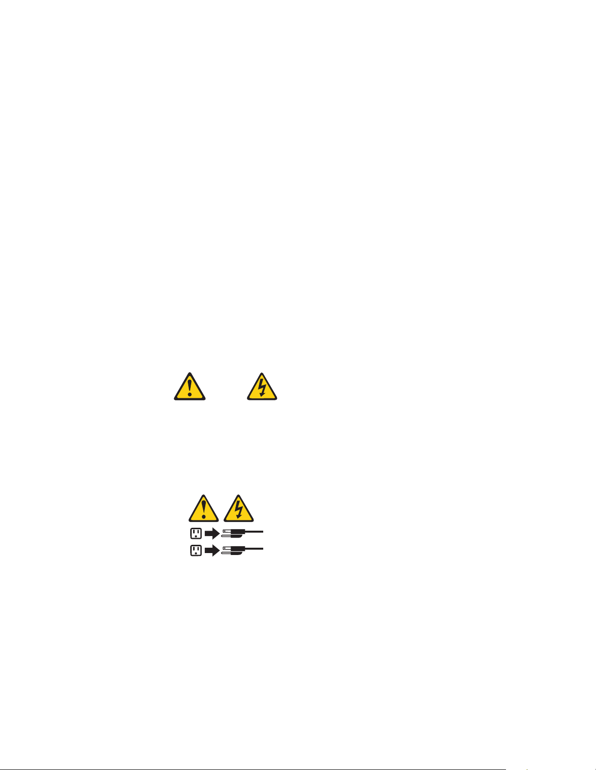
Statement 5
CAUTION:
The power control button on the device and the power supply do not turn off
the electrical current supplied to the device. The device also might have more
than one power cord. To remove all electrical current from the device, ensure
that all power cords are disconnected from the power source.
2
1
The expansion unit is designed to run contin uou sly, 24 hours a day. Turn off the
power only when at least one of the following is true:
• Instructions in a hardware or software procedure require you to turn off the
power.
• A ser vi c e te chnician tells you to tu rn off the power.
• A power outage or emergency situation occurs (see “Turning off the expansion
unit in an emergency” on page 5).
Use the following procedure to turn off the expansion unit:
1. Power down the server attached to the expansion unit.
4 IBM Netfinity EXP300 - Type 3531 Hardware Maintenance Manual
Page 13

2. Make sure that all amber fault LEDs are off. If any fault LEDs are lit (drives,
power suppl ies, or ESM boards), correct the p roblem before you turn off the
power. For guidance, refer to “Symptom-to-FRU index” on page 7.
3. Turn off both power supplies.
Turning off the expansion unit in an emergency
Attention: Emergency situations might include fire, flood, extre me we ather
conditions, or other hazardous circumstances. If a power outage or emergency
situation occurs, always turn off all power switches on all computing equipment.
This will help safeguard your equipment from potential damage due to electrical
surges when power is restored. If the expansion unit loses power unexpectedly, it
might be due to a hardware failure in the power sy stem or midplane (see “Symptomto-FRU index” on page 7).
Use the following procedure to turn off the expansion unit during an emergency
situation:
1. Power down the server attached to the expansion unit.
2. If you have tim e, st op al l act ivi ty an d chec k the LEDs ( fr ont and back ). Make n ote
of any fault LEDs that are lit so that you can corr e ct the problem when you turn
on the power again.
3. Turn off all power supplies; then, unplug the power cables from the expansion
unit.
Turning on the expansion unit after an
emergency
Use the following procedure to restart the expansion unit if you turned off the power
supplies during an emergency shutdown, or if a power failure or a power outage
occurred:
1. After the emergency situation is over or power is restored, check the expansion
unit for damage. If there is no visible damage, continue with Step 2; otherwise,
consult with customer to repair the unit .
2. After you have checked for damage, plug in the expansion-unit power cables and
turn on the power switches.
3. Check the syst em docu mentat i on for the har dwa r e devi ces y ou in tend t o turn on,
and determine the proper power-on sequence.
Note: Be sure to turn on the IBM Netfinity EXP300 before or at the same time
you turn on the sy ste m unit.
4. Turn on each device, based on the power-on sequence.
5. Turn on both power supplies on the back of the IBM Netfini ty EX P 300.
6. Only the po we r ( green) LEDs on the front and back shou ld be on. If one or more
of the fault (amber) LEDs are on , refer to “Sympt om- to-FRU index” on pa ge 7 for
instructions.
7. Use your installed software application as appropriate to check the status of the
expansion unit.
Operating specifications
The following table summarizes the operating specifications of the expansion unit.
Netfinity EXP300 Type 3531 5
Page 14

Electrical input
• Sine-wave input (50 to 60
Hz) is required
•Input voltage:
—Low range:
– Minimum: 90 V ac
– Maximum: 127 V ac
— High range
– Minimum: 198 V ac
– Maximum: 257 V ac
— Input kilovolt-amperes
(kVA) approximately:
– Minimum
configuration: 0.06
kVA
–Maximum
configuration: 0.45
kVA
Environment
• Air temperature:
— Expansion unit on: 10°
to 35° C (50° to 95° F)
Altitude: 0 to 914 m
(3000 ft)
— Expansion unit on: 10°
to 32° C (50°
to 90° F) Altitude: 914 m
(3000 ft.) to 2133 m (700
ft)
• Humidity: 8% to 80%
Size (with front panel and
without mounting rails
• Depth: 53.8 cm (21.2 in)
• Height: 12.8 cm (5 in)
• Width: 44.7 cm (17.6 in)
Weight
• Standard expansion unit as
shipped: 22.5 kg (49.5 lbs)
• Typical expans ion un it fully
loaded: 36.1 kg (79.4 lbs)
Acoustical noise emissions
values
For open bay (no drives installed)
and max imum system
configurations (14 hard disk
drives installed).
• Sound power (idling):
— 5.6 bels (open bay)
— 5.7 bels (typical)
• Sound power (operating):
— 5.6 bels (open bay)
— 6.5 bels (typical)
• Sound pressure (idling):
— 44 dBA (open bay)
— 47 dBA (typic al)
• Sound pressure (operating):
— 44 dBA (open bay)
— 54 dBA (typic al)
These levels are measured in
contr olled acoustical
environments according to ISO
7779 and are reported in
accordan ce with I SO 9296. The
declared sound power levels
indicate an upper limit, below
which a large portion of machines
operate. Sound pressure levels i n
your location might exceed the
average 1-meter values stated
because of room reflections and
other nearby noise.
System-management software support
The Net f i ni t y EX P 3 0 0 p rovides so ftware alert fu nctions through the sy st e m m o ni t or
function s p rovided in the IBM Netfinity Manager, IBM Netfinity Direc tor, and IBM
ServeRAID manager software.
The following alerts are supported:
• Disk drive disabled
• Power supply failure
• Cooling failure
• IBM Netfinity EXP300 too hot
• Vital Product Data for su b components
Note: You must have the correct level of manageme nt software on your server to
enable this functionality.
6 IBM Netfinity EXP300 - Type 3531 Hardware Maintenance Manual
Page 15

Y o u must use ServeRAID version 4.10 or later for your ServeRAID controller to repo rt
statu s and alerts p rop e rly. To downl o a d th e la te st ServeR AID family so f tware, visi t
the following IBM web site at: http://www .ibm.com/pc/support.
For up-to-date information about the IBM Netfinity Manager and Netfinity Director
software support available for your EXP30 0, visit the foll owing IBM Web site at:
http://www.ibm.com/pc/us/netfinity
For Netfinity Manager users, download Netfinity Manager version 5.20.6 SP1 or later.
For Netfinity Director users, download Netfinity Director, UM Server extensions
version 2.12 SP1.
Symptom-to-FRU index
This index supports Netfin it y EXP300 – Type 3531 expansion units.
Use this chart to find solutions to p roblems that have definite symptoms.
Problem indicator FRU/Action
Amber LED on Drive CR U 1. Failed drive
Refer to “Replacing hot-swap drives” on page 20
Amber LED on ES M b oard 1. Failed ESM board
Refer to “Replacing an ESM board” on page 24.
Amber LED on front panel 1. Indicates that a Fault LED somewhere on the expansion
unit has been turned on. (Check for amber LEDs and
CRUs.)
Refer to “Rear controls, indicators, and connectors” on page
15
Amber LED on an d green LED off 1. Tur n on all power supplies
2. Power supply
Amber and g reen LE Ds on 1. F ailed power supply
All green LEDs off 1. Check that all expansion unit power cables are plugged
in and the power is on. If applicable, check that the
main circuit breakers for the rack are turned on.
2. Check the main circuit breaker and ac outlet.
If the external switch 1 is set to Off, the SCSI controller
must be cabled to the EXP300 and turned on.
3. Power supply
4. Mid-plane board
Amber LED flashing on Drive CRU 1. Drive rebuild or identity is in process.
Amber LED flashing on power
supply
Amber LED on and green dc power
LED off on power supply
Netfinity EXP300 Type 3531 7
1. Power supply
1. Turn power switch on
2. Power supply
Page 16

Problem indicator FRU/Action
Amber LED on and green ac power
LED off on power supply
Green LED on (Drive CRU ID=6) 1. If not curr e ntly clus ter configured, po we r cycle the
One or more gre e n LEDs off (one or
two drive CRUs)
One or more green LEDs off (all
drive CRUs or those on one bus)
One or more green LEDs off (front
panel)
Intermi ttent or sporadic power loss
to the expansion unit
Unable to access drives on on e or
both SCSI buses
1. Make sure AC power is good at the source.
2. Power Cord
3. Power supply
Netfinity EXP300 to re-enable ID=6.
( No activity to the drive. No action is required.)
( No activity to the drive. No action is required.)
1. Check SCSI-bus cables and connections.
2. Use RAID management software to check the SCSI-bus
status.
3. ESM board
1. Make sure the cables are plugged in and power supplies
are turned on.
2. Power supply
1. Check the ac power source
2. Resecure all installed power cables and power supplies
3. Power supply
1. Make sure SCSI cables are unda m a ge d an d pro per ly
connect ed.
2. Check the drive SCSI ID settings. Ensure that option
switches 1 and 3 (inside the switch car d) are set to the
appropriate positions.
Attention:
Change switch positions only when you r ho st se rver and
expansion unit is turned off.
3. ESM board
4. Brid ge card (All high address or all low address harddisk drive failed)
Rando m e rro rs 1. Mid-plane
Locati ons
Getting started
You can insta ll the EXP300 expansion unit in the followi ng types of enclosures:
• An Electronic Industries Association (EIA) 310 standard rack cabinet
• The IBM Netfinity EXP300 Rack-to-Tower Conversion Kit
• An IBM Netfinity NetBAY enclosure
8 IBM Netfinity EXP300 - Type 3531 Hardware Maintenance Manual
Page 17
You will need a flat-blade screwdriver and a Phillips-head screwdriver to install your
expansion unit. Each type of enclosure comes with general installation instructions
for installing optional dev ices .
Before you begin, revi e w th e following assum p tions:
• If you are installing the expansion unit in a rack, you have already installed the
other components in the rack and moved the rack t o its permanent operating
location.
• Y ou have already installed and configured the host controllers and appropriate
host adapters.
• There are 68-pin VHDCI SCSI cables attached to the host controllers, ready for
final connection to the expansion unit.
• The installation site meet s al l area, environmental, power, and site requirements
for the expansion unit. Refer to the expansion unit requirements listed under
“Operating specifications” on page 5.
Preparing the expansion unit
This sec tion e xplain s how to r emove th e CRUs an d set t he int erfac e opt ion s to pr e par e
the expansion unit for installation.
Removing CRUs
It is easier to lift the expansion unit and install it in a rack or tower enclosure if you
remove all CRUs (disk drives, po wer supplie s, an d ESMs ) first. A fully loaded
expansion unit with 14 disk drives and two power supplies with built-in fans
installed weighs 36.1 kg (79.5 lb). The standard unit with two power supplies weighs
22.5 kg (49.5 lb). If you remove all the CRUs, you can reduce the overall weight.
Attention: If you have data stored on the drives, label the drives before you remove
them. Then, when you replace the drives, install each one in the same drive bay from
which you removed it.
See “Locations” on page 8 for information on removing the CRUs.
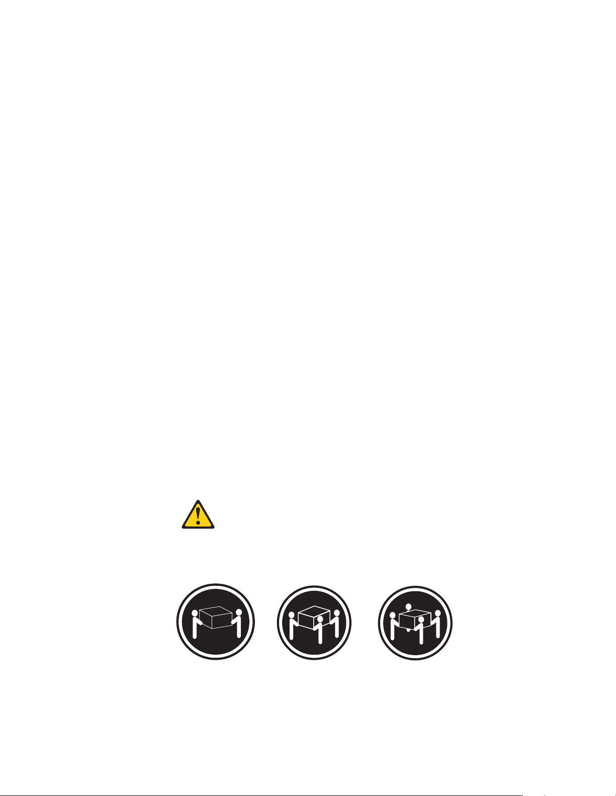
Statement 4
≥18 kg (37 lbs) ≥32 kg (70.5 lbs) ≥55 kg (121.2 lbs)
CAUTION:
Use safe practices when lifting.
Netfinity EXP300 Type 3531 9
Page 18
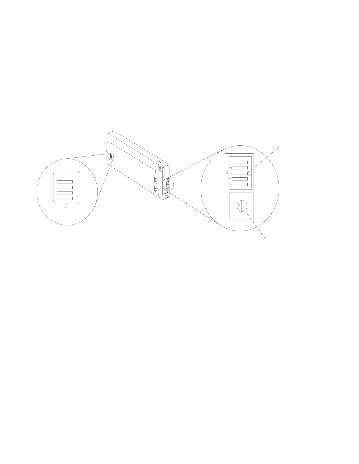
Setting the interface options and ID settings
On
1
2
3
4
Internal
options switches
When you install a drive CRU in the expan sion unit , the drive tr ay plugs into a
printed circuit board called the midplane. The midplane sets the SCSI bus number and
ID automatically.
The switc h card located on the b a ck of the expansion unit has five external option
switches, four internal option switches, and a unit ID switch. It is e a sier to set these
switches before you install the expansion unit in a rack or tower enclosure.
Attention: Always set the option switches while the expansion unit and host server
are turned off. Failure to do so will result in loss of data.
External option switches
3
4
2
5
1
6
0
7
9
8
3
2
4
1
5
0
6
9
7
8
Unit ID switch
External option switches
The five opt ion switches on the exterior of the switch card are: Option switch 1
controls the power supply to the expansion unit. Option switches 2 through 5 are
reserved; leave these switches in the default positions.
Option switch 1 — Power-control switch
When this opti on switch is set to Off, the expansi on unit turns on and off
automatically when you turn the host machine on and off. This occurs only if
termination power is present (the termination-power LED is on) at the
external SCSI connector.
When this option switch is se t to On (the default), you must turn the
expansion unit on and off separately.
Option switches 2 through 5 — Reserved
These opti on switches are reserved; leave these option switches set to the
default positions. Set switches 2 through 5 (On , On , Off, Off) respectively.
Internal option switches
The four option switches ins ide the switch card are: Option swi tch 1 controls SCSI
addresses for the rack and tower installation modes. Option switch 2 controls the
fron t p anel power and fault LEDs for the rack and tower. Option switch 3 controls the
SCSI bus, and option switch 4 is reserved; leave this switch in the Off position.
10 IBM Netfinity EXP300 - Type 3531 Hardware Maintenance Manual
Page 19

Attention: A loss of data can occur if y ou change the position of inte rnal option
switch 1 or interna l option swi t ch 3 af te r sto ring data on the drive s. Ref e r to
“Conversion of EX P 300 to a tower or from a tower” on page 25 if you want to chan ge
the configuration of your expansion unit from a rack (internal switch 1 Off) to a tower
(internal switch 1 On) or from a tower to a rack orientation.
SCSI buses and IDs
There are two SCSI buses (bus 1 and bus 2) in the expansion unit. Each bus
uses seven SCSI ID numbers. Each disk drive within the expansion un i t has a
unique SCSI bus an d ID assignment, based on its physical locati on in the
expan s ion unit and the setting of op t ion switch 1 (inside the switch card) .
Option switch 1 — SCSI-address switch
This switc h sets the order of the SCSI IDs. The default is Off for a rack unit
installation. In the rack unit, the SCSI IDs are from left to right, 0, 1, 2, 3, 4, 5,
6, 8, 9, 10, 11, 12, 13, and 14. When this switch is set to On for a tower
installati on , the SCSI IDs are from top to bottom, 0, 1, 2, 3, 4, 5, 6, 8, 9, 10, 11,
12, 13, and 14.
Option switch 2 — Rack/tower LED switch
Note: If you are installing the EXP300 in a tower, refer to the Rack-to-Tower
Conversi on Kit instructions for option switch settings and labeling
information.
Option switch 2 is the rack and tower mode switch. Put this switch in the Off
position when the unit is placed in a rack and in the On position when the
unit is placed in a tower.
When shipped, option switch 2 is set to the rack (Off) position. When you
make the chan ge to i nsta ll i t in to a tower, option switch 2 is in the On posit i on
and the general system error indicator on the front panel is swapped with the
power-on LED, placing the green power-on LED above the general-system
error indicator.
Set this switch to Off (the default) for a rack unit and On for a tower unit.
Option switch 3 — SCSI bus split switch
This switch controls the SCSI bus configuration. When this option switch is
set to Off (the default), the expansion unit configuration is set as a single SCSI
bus mode. When this option switch is set to On, the expansion unit
configuration is set as a dual SCSI bu s (split bus) mode .
Option switch 4 — Reserved
This switch is reserved; leave this option switch set to Off (the default).
Unit ID dial switch
The unit ID swit ch has 10 settings. You can use these setting s ( 0 through 9) to set an
ID for the expansion unit. System-management software, such as IBM Netfinity
Director, uses this expansion unit ID when it provides data and alerts for the
expansion unit.
Netfinity EXP300 Type 3531 11
Page 20
Important inform a tio n for IB M Serve RAID:
If you are using a ServeRAID software version earlier than the Version 3.50, the
Vi e w Configuration sc reens might show SCSI IDs or bay numbers. I f t he data
shown on the View Configurat ion screen begins with 0, it denotes SCSI IDs. If the
data shown on the View Conf iguration screen begins with 1, it denotes bay
numbers.
Netfinity EXP300 bays
The following sections describe the hot-swap CRUs, the switch card bay, and the
bridge card bay on the Netfinity EXP300 expansion unit.
Wi th the hot-swap feat ures of the Netfin ity EXP300, you can remove an d replace hard
disk dri ves, power supplies/fans, and ESM boards without turning off the expansion
unit. Therefore, you can maintain the availability of your system while a hot-swap
device is removed, installe d , or replaced .
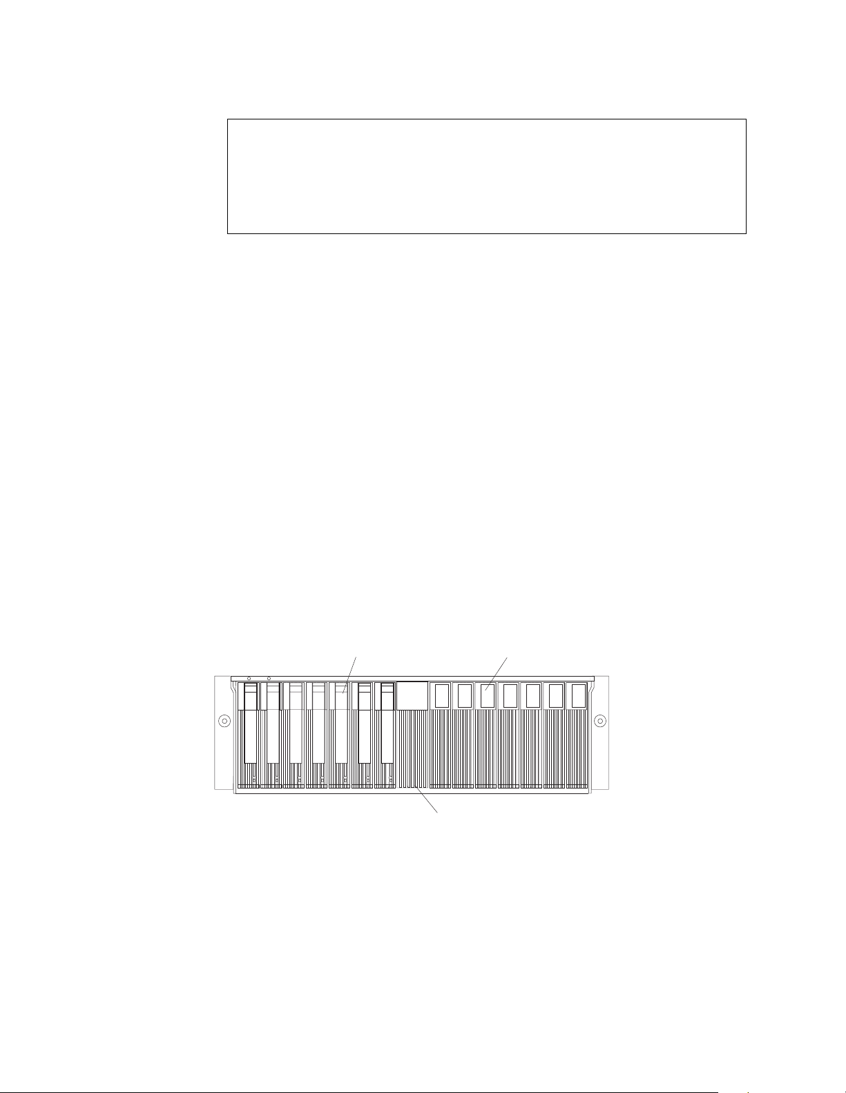
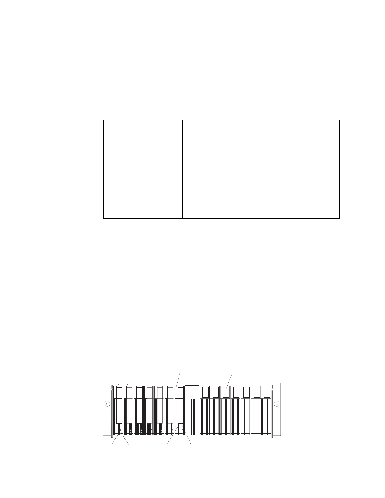
Hot-swap drive bays
The following illustration shows the location of the hot-swap drive bays accessible
from the front of your expansion unit. The Netfinity EXP300 supports up to 14 IBM
Ultra160 SCSI or Ultra2 SCSI hard disk drives. These drives come pre installed in a
drive tray. The drive and tray assembly is called a drive CRU (customer replaceable
unit). You can install the drive CRUs in the 14 drive bays on the front of the expansion
unit.
In the following figure, seven of the 14 bays contain drive CRUs, and seven bays
contain filler panels. To maintain proper cooling within your expansion unit, always
keep a filler panel in each drive bay that does not contain a drive CRU. For
information on installing and replacing drive CRUs, refer to “Working wit h hot-swap
drives” on page 17.
Hot-swap drive bays
Bridge card bay
Attention: Never hot-swap a drive CRU when its green activity light emitting diode
(LED) is flashing. Hot-swap a drive CRU only when its amber fault LED is lit (not
flashing) or when the drive is in active with the green activity LE D off (not flashing).
Filler panel
Bridge card bay
The brid ge car d is a cc essib le f r om th e front of the un it. You can repl ace t he brid ge card
CRU but you must turn off the expansi on unit before doing so. Refer to “Replacing a
bridge card” on page 22 for step-by-ste p instructions.
12 IBM Netfinity EXP300 - Type 3531 Hardware Maintenance Manual
Page 21
Attention: Never remove the bridge card while the expansion unit is turned on.
Refer to “Turning the expansion unit on and off” on page 3.
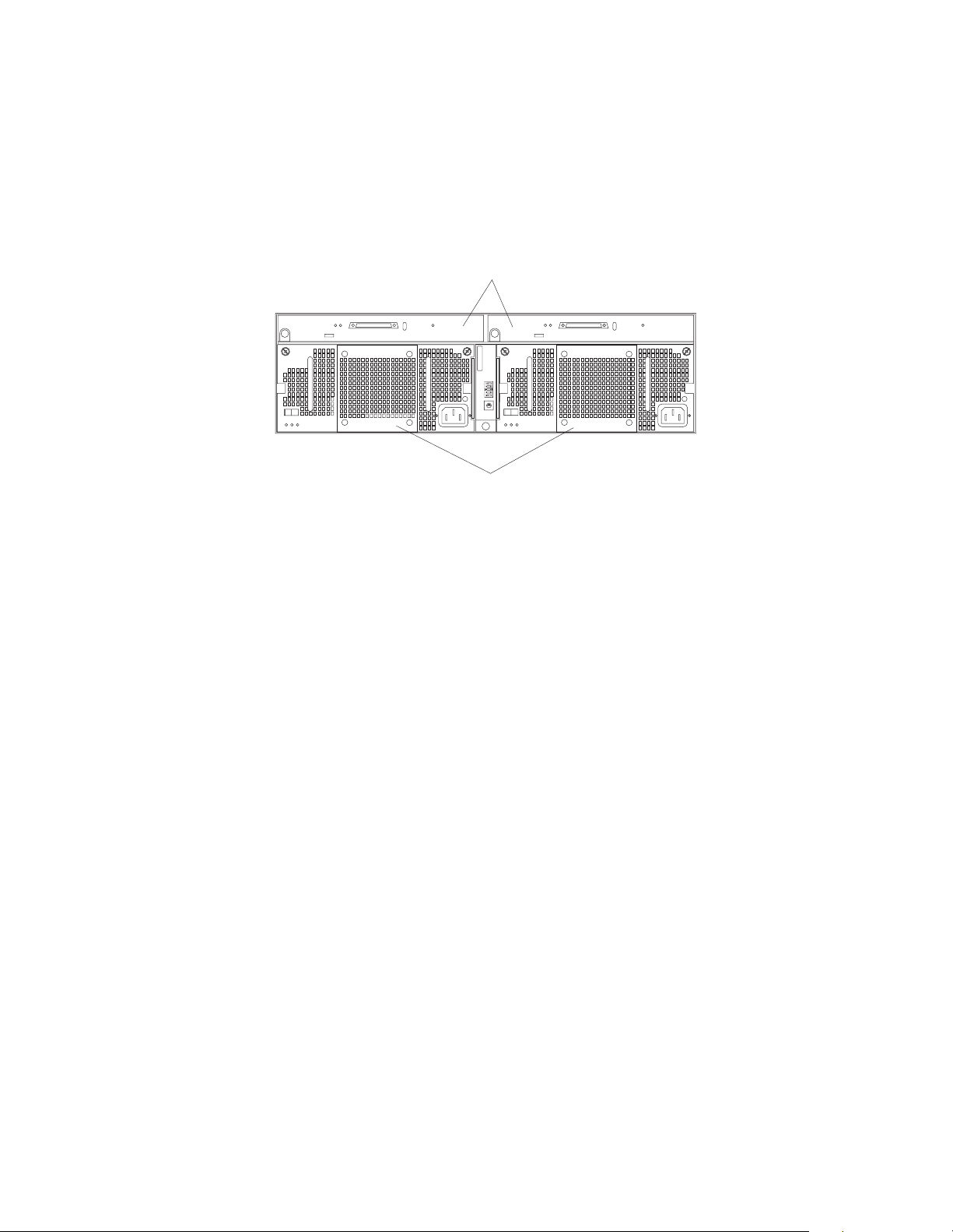
ESM and power supply bays
The following illustration shows the location of the environmental services monitor
(ESM) bays (for the hot-swap ESM boards) and the power supply bay s where the hotswap po wer supp l ie s a re l o ca te d.
Hot-swap ESM bays
0
1
9
2
8
3
7
4
6
5
Hot-swap power supply/fan bays
Hot-swap ESM bays
These are the locations of the environmental services monitor (ESM) boards.
The ESM boards provide a SCSI interface to the drives and monitor the
overall status of the expansion unit. The ESM boards are hot-swappable.
Refer to “Replacing an ESM board ” on page 24 for step-by-step instructions.
Hot-swap power supply/fan bays
Your expansion unit comes with two 500 Watt hot-swap and redundant
power supplies with built-in fans. The power supplies are redundant in that
a single power supply can provide adequate power and cooling for the entire
expansion unit. A single power supply can support up to 14 disk drives;
however, both power supplies must be install ed , even if one power supply is
not operational. Refer to “Working with hot-swap power” on page 21 for
step-by-step instructions.
Switch card bay
Your ex p a n s ion unit come s wi t h a swi t ch card that cont a i ns five e xt e rna l o p tion
switch e s an d fo u r int ernal option s wi t ches. The swit ch ca rd is lo ca t ed on the back of
the expansion unit between the two power supplies. The switch card contains
switches that control how pow er is sup plied to the e xpans io n unit and wh at
expansion unit services are enabled (fo r example , switchi ng between a tower
configuration and a rack configur atio n or switching be twee n a single bus and a dualbus configuration.) In a dual-bus configuration, each bus uses seven drives. A singlebus configuration uses all 14 drives. To access the four internal option switches, you
must turn off the expansion uni t; then r emove the switch car d. Refer to “Replacing the
switch card” on page 23 for step-by-step instructions.
Attention: Never remove the switch card or change the switch card settings while
the expansion unit and host server is turned on. Refer to “Turning the expansion unit
on and off” on pa g e 3.
In addition to the internal and external option switches, the switch car d also has a 10position unit ID switch for setting the expansion unit ID using values 0 through 9.
Netfinity EXP300 Type 3531 13
Page 22

System-management software, such as IBM Netfinity Manager™, uses the ID when it
provides data and alerts for the expansion unit.
For mor e information on option switch settings, see “Setting the interf ace options and
ID settings” on page 10.
The following illustration shows the location of the switch card on the expansion unit.
Switch card
0
1
9
2
8
3
7
4
6
5
External option switches
1
2
3
4
5
3
2
4
1
5
0
6
9
7
8
Unit ID switch
Front controls, indicators, and devices
The primary controls on the front of the expansion unit are shown in the following
illustration.
Power-on LED (green)
Drive CRU
Activity
LED (green)
General-system-
error LED (amber)
Fault
LED (amber)
Tray
handle
Bridge
card bay
Latch
Filler panel
Drive bays
Power-on LED (g reen)
This green light indicates that the unit has good dc power.
14 IBM Netfinity EXP300 - Type 3531 Hardware Maintenance Manual
Page 23

General-system-error LED (amber)
When lit, this amber LED indicates that the unit has a fault, such as in a power
supply, ESM boar d, or hard disk drive.
Bridge car d bay
This is the l ocation of the bridge card CRU.
Filler panel
Expansion units shipped without a full set of drives (14) contain filler panels
in the unused drive bays. Before installing new drives, you must remove the
filler panels and save them for later use. Each of the 14 bays must always
contain either a filler panel or a drive CRU.
Drive bays There are 14 drive bays that contain either a drive CRU or a filler panel.
Latch This multipu rpo se blue latch releases or locks the dr ive CR U in pl ace.
Tray handl e You can use this multipurpose handle to insert and remove a drive CRU
in the bay.
Fault LED (amber)
Each drive CRU has a fault LED. When lit, this amber LED indicates a drive
failure. When flashing, this amber LED indicates that a drive Identify or
Rebuild is in progress.
Activity LED (green)
Each drive CRU has an activity LED. When flashing, this green LED indicates
drive activity.
Drive CRU You can install up to 14 hot-swap drive CRUs in the expansion unit. Each
drive CRU consists of a hard disk drive and tray.
Rear controls, indicators, and connectors
Two hot-swap power supplies with built-in fans and two environmental services
monitor (ESM) boards are accessible from the back of the expansion unit. These
components contain several user indicators and connectors.
Power-supply controls, indicators, connectors
The followi ng is a list of th e contr o ls, in dic ators, and con nect or s at back of the EXP300
expansion unit. A description of each item is included:
Thumbscrews Thumbscrews
Handle Handle
AC power LED (green)
DC power LED (green)
Fault LED (amber)
Power
on/off
switch
supply/Fan CRU
Power
0
1
9
2
8
3
7
4
6
5
Power
on/off
switch
AC power connectorAC power connector
Power
supply/Fan CRU
Thumbscrews Loosen the thumbscrews to remove or install a power supply.
Netfinity EXP300 Type 3531 15
Page 24
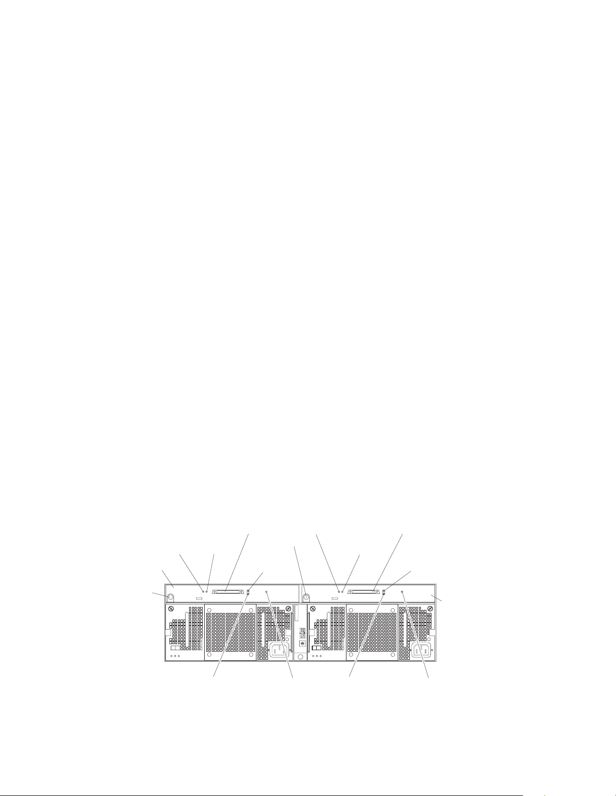
AC power conn ect or
The power cord for the power supply connects here.
Power-supply/Fan CRU
The two hot-swap power supplies with built-in fans are located on the back of
the expansion unit.
Attention: The EXP300 comes with two power-supply/fan units installed.
When one power supply fails, the power-supply unit must be replaced to reestablish redundancy. When replacing the failed unit with the new power
supply unit, ensure that this operation is performed in less than 10 minutes to
prevent any overheating.
The fan that is visible from the rear of the power supply is an auxiliary fan
that is normally off. This fan turns on only when the main fan within the
power supply fails.
Power on/off switch
Use this switch to turn the power su pply on and off.
Fault LED (amber)
When completely lit, this amber fault LED indicates a power supply failure or
that a red u n d ant power s u p p l y i s not on. This LED also fla shes when th e
built-in fan fails.
DC power LED (green)
This green LED is lit when the expansion unit is turned on and is su pplying
both 5 V and 12 V dc power .
TerminationLED (green)
ESM board
Push pin
AC power LED (green)
This green LED is lit when the expansion unit is receiving ac power.
Handle s The two handles are used for installing and removing the power supply.
ESM board user controls
Two environmental services monitor ( ESM) boards are accessible from the back of the
expansion unit. These components contain several user contr ols, indicators, and
connectors.
Termination-
power
LED (green)
Push pin
0
1
9
2
8
3
7
4
6
5
SCSI Bus
connector 1
LVD/SE
LED (green)
Activity
LED (green)
ESM board
power
SCSI Bus
connector 2
LVD/SE
LED (green)
Activity
LED (green)
SCSI reset
LED (green)
Fault
LED (amber)
SCSI reset
LED (green)
Fault
LED (amber)
ESM board The environ mental services monitor (ESM) boards contain the SCSI
controls and LEDs.
16 IBM Netfinity EXP300 - Type 3531 Hardware Maintenance Manual
Page 25

Fault LED (amber)
When lit, this amber LED indicates an ESM board failure.
SCSI reset LED
When li t, this green LE D in d i ca t e s a S C S I bu s res e t .
Push pins Each ESM board has an orange push pin to the bottom left of the board.
Use the orange push pin and lever to remove and insert the ESM board.
Termination-power LED (green)
When lit, this green LED indicates that terminatio n pow er is present. (When
a termination-power LED is lit, it indicates that the other end of the cable is
connected to a powered-on controller.) Each external bus has a separate
termination-po w e r LED .
LVD/SE LED (green)
When lit, this green LED indicates that the external host bus is in low voltage
diffe rential (LVD) mode. When this LED is of f , this indic ates that the external
host bu s i s in single-en de d (SE) mod e. Each extern a l bu s has a se p a r at e
LVD /SE LED. Only LVD host bus controllers are supported.
SCSI bus connecto r
The 68-pin Very High Density Connector Interface (VHDCI) connectors are
for attaching your SCSI cables to SCSI bus 1 and SCSI bus 2.
Activity LED (green)
When lit, this green LED indicates there is activity on the external SCSI bus.
Each external bus has a separate activity LED.
Working with hot-swap drives
Before you begin
• Read the safety and handling guidelines provided in “Safety information” on
page 41 and "Handling electrostatic discharge-sensitive devices."
• Ensure that your current system configuration is working properly.
• Back up all important data before you make changes to storage devices, such
as hard disk drives.
This section explains how you can increase the expansion unit capacity by adding
more drives or replacing existing drives with larger capacity drives.
Before you install or remove drive CRUs, review the following information:
Hot-swap hardware
You can replace a failed hard disk drive without turning off the expansion
unit. Therefore, you can continue to operate your system while a hard disk
drive is removed or installed. These drives are known as hot-swap drives.
Drive CRUs Y our expans i on unit suppor ts IBM Ultra160 and IBM Ultra2 SCSI hard
disk drives. These IBM drives come pre-installed in a drive tray, ready for
installation. (Do not detach th e drive from the tray.) This drive and tray
assembly is called a drive customer replaceable unit (CRU). You can install the
drive CRUs directly into the 14 drive bays on the front of the expansion unit.
Be sure to record the location information for each drive before you remove it.
Ensure that you keep track of the drives and their corresponding bays.
Netfinity EXP300 Type 3531 17
Page 26
Attention: If you re-install a drive in the wrong bay, you could lose data.
Drive LEDs Each drive bezel has two LEDs, whic h i n dicate the st a tus for tha t
particular drive. The drive LED states and descriptions are as follows:
LED LED State Description
Activity LED Green/flashing Flashes during
read/write or inquiry
op e rat i ons t o th e dri v e
Fault LED A mber /fla shing Flas hes to indicate a
drive rebuild is under
way, or that a drive has
been identified by
software
Fault LED Amber On On to indicate a drive
failure
Filler panel
Expansion units are shipped without a full set of drives (14). They contain
filler panels in the unused drive bays. Before installing new drives, you must
remove the filler panels, which should be saved. Each of the 14 bays must
always contain either a filler panel or a drive CRU.
Hard disk drives
You can install only slim hot-s w ap drive CRUs in the EXP3 0 0 expansio n un it.
Installing hot-swap drives
Use the following procedure to install drives in the expansion unit. You can install
additional drives while the expansion unit is turned on.
Note: If you are replacing a drive, see “Replaci ng hot-swap drives” on page 20.
1. Read the instructions th at come with the drive CRU .
2. Check for fault LEDs. If any amber LEDs are lit, refer to “Symptom-to-FRU
index” on page 7.
Drive CRU
Filler panel
Activity LED
Fault LED
Latch
Tray handle
18 IBM Netfinity EXP300 - Type 3531 Hardware Maintenance Manual
Page 27
3. Determine the bay into which you want to install the drive.
4. Remove the filler panel.
a. Insert a finger into the square hole at the top of the filler panel to grip and pull
the panel out of the drive bay.
b. Save the filler panel for later use.
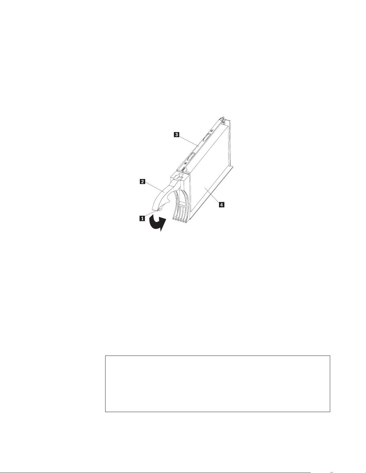
5. Install the drive CR U :
Note: The hard disk drive comes with a tray already attached. Do not attempt
to detach the dri ve Þ4Ýfrom the trayÞ3Ý.
a. Release the blue latch Þ1Ýon the drive CRU by pressing on the inside of the
bottom of the tray handle Þ2Ý.
b. Pull the handle Þ2Ý on the tray out into the open position.
c. Slide the drive CRU into the empty bay until the tray handle Þ2Ý touches the
expansion-unit bezel.
d. Push the tray handle Þ2Ý down into the closed (latched) position.
6. Check the drive LEDs.
a. When a drive is ready for use, the green activity LED and the amber fault
LED are off.
b. If the amber fault LED is on, remove the drive from the unit and wait 10
seconds; then, reinstall the drive.
ServeRAID information
In some cases, the ServeRAID controller will automaticall y reset the drive to th e
Hot Spare or Rebuild state. If the drive state change does not occur automatically
(amber LED stays lit), refer to your ServeRAID documentation for information
about manually changing the state of the drive from the current state to another
state, such as Hot Spare or Ready. The amber LED should turn off within 10
seconds after the drive-state chang e .
7. Configure the drive using the appropriate software.
Netfinity EXP300 Type 3531 19
Page 28
Replacing hot-swap drives
Drive problems include any malfunctions that delay, interrupt, or prevent successful
I/O activity between the hosts and the hard disk drives in the expansion unit. This
includes transmission pr oblems between the h ost contr oll ers, the ES M boards, and the
drives. This section explains how to replace a failed drive.
Attention: Failure to replace the drives in their correct bays might result in loss of
data. If you are replacing a drive that is part of a RAID level 1 or RAID level 5 logical
drive, ensure that you install the replacement drive in the correct bay.
Check the hardware and software documentation provided with your system to see if
there are restrictions regarding hard disk drive configurations. Some system SCSI
configurations might not allow mixing different drive capacities or types within an
array.
To replace a hot-swap drive:
1. Determine the location of the drive that you want to remove.
Attention: Never hot swap a d ri ve CRU when its green activ ity LED is fla shing.
Hot swap a drive CRU only when its amber fault LED is lit (not flashing) or when
the drive is inactive (activity LED is off).
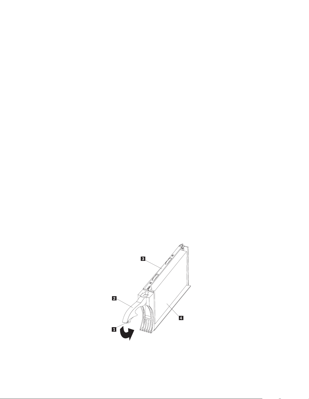
2. Remove the drive CRU.
a. Press on the inside of the bottom of the tray handle Þ2Ýto release the blue
latch Þ1Ý.
b. Pull the handle Þ2Ý on the tray Þ3Ý out into the open position.
c. Lift the drive tray partially out of the bay.
d. To avoid possible damage to the drive Þ4Ý, wait at least 20 seconds before
fully removing the drive CRU from the expansion unit, to allow for the drive
to spin down.
e. Verify that there is proper identification (such as a label) on the drive CRU,
and then slide it completely out of the e xpa nsion unit.
3. Install the new drive CRU.
a. Gently push the drive CRU into the empty bay until the tray handle Þ2Ý
touches the expansion unit tray.
b. Push the tray handl e Þ2Ý down into the closed (latched) position.
20 IBM Netfinity EXP300 - Type 3531 Hardware Maintenance Manual
Page 29

4. Check the drive LEDs.
a. When a drive is ready for use, the green activity LED and the amber fault
LED are off.
b. If the amber fault LED is on, remove the drive from the unit and wait 10
seconds; then, reinstall the drive.
ServeRAID information
In some cases, the ServeRAID controller will automaticall y reset the drive to th e
Hot Spare or Rebuild state. If the drive state change does not occur automatically
(amber LED stays lit), refer to your ServeRAID documentation for information
about manually changing the state of the drive from the current state to another
state, such as Hot Spare or Ready. The amber LED should turn off within 10
seconds after the drive-state chang e .
Working with hot-swap power
Before you begin
• Read the safety and handling guidelines provided in “Safety information” on
page 41 and "Handling electrostatic discharge-sensitive devices."
The power supplies are customer replaceable units (CRUs) and do not require
preventive maintenance.
• The power supplies must always be installed in the proper place to maintain
proper expansion unit cooling.
• Use only the supported power supplies for your specific expansion unit.
Removing a hot-swap power supply/fan unit
Complete the following steps to remove a hot-swap power supply:
1. Turn off the power supply.
2. Unplug the power supply cord from the electrical outlet.
3. Disconnect the power cord from the power supply.
4. Loosen the p owe r supply thumbscrews Þ1Ý.
5. Grasp the handles Þ2Ý on each side of the power supply, and pull the unit out of
the expansion unit.
Netfinity EXP300 Type 3531 21
Page 30

0
9
1
8
2
7
3
6
4
5
Installing a hot-swap power supply / fan unit
Complete the follo win g steps to insta ll a hot-swap pow er supply:
1. Ensure that the power supply you are installing is turned off.
2. Grasp the handlesÞ2Ýand slide the power supply into the expansion unit.
3. Tighten the power supply thumbscrews Þ1Ý.
4. Connect the power cord to the powe r supply.
5. Plug the supply power cord into a properly grounded electrical outlet.
If you just installed a second (redundant) supply, the fault (amber) LED will light
because its power switch is turned off.
6. Turn on the power supply.
If you just installed a second (r ed undant) supply, after you turn on the power, the
fault (amber) LED will turn off and the ac and dc power (green) LEDs wil l turn
on.
Working with cards and boards
Before you begin
• Read the safety and handling guidelines provided in “Safety information” on
page 41 and "Handling electrostatic discharge-sensitive devices."
• Ensure that your current system configuration is working properly.
• Back up all important data before you make changes to storage devices, such
as hard disk drives.
The expansion unit bridge card, switch card, and ESM boards are customer
repla ceabl e un its ( CRU s). This se cti on co n tains st e p-by -st ep inst r uct io ns for r emov ing
and replacing each device.
Replacing a bridge card
To replace the bridge card CRU in the EXP300 expansion unit, follow the instructions
for removing the bridge card and installing a bridge card.
22 IBM Netfinity EXP300 - Type 3531 Hardware Maintenance Manual
Page 31

Removing a bridge card:
Attention: Before removing the EXP300 bridge card, you must turn off the expansion
unit. Refer to “Turning the expansion unit on and off” on page 3 for detailed
instructions.
Complete the following steps to remove the EXP300 bridge card:
1. Turn off the expansion unit. Refer to “Turning the expansion unit on and off” on
page 3.
2. Remove the driv e CRUs or blank fill er pane ls fr om the left and right of the bridge
card bay. Refer to “Repl acing hot-swap drives” on page 20.
3. Squeeze the bridge-card cover Þ1Ý clips, and pull the bridge card cover Þ1Ý off.
4. Lift the tr ay handl e Þ2Ý, and pull the tray Þ3Ý that contains the bridge card out of
the bridge card bay.
Installing a bridge card:
Attention: Make sure the expansion unit is turned off before installing a bridge card.
Refer to “Turning the expansion unit on and off” on page 3.
Complete the following steps to install the EXP300 bridge card:
1. Make sure the expansion unit is turned off.
2. Hold the bridge card tray Þ3Ý so the tray handle Þ2Ý is at the top of the bridge card
tray and pointing outward.
3. Slide the tray Þ3Ý that contains the bridge card into the bridge card bay.
4. Push the tray han dl e Þ2Ý down, locking the bridge-card tray into place.
5. Replace the bridge card cover Þ1Ý by squeezing each of the four tabs, locking the
cover into place.
6. Turn on the expansion unit. Refer to “Turning the expansion unit on and off” on
page 3.
Replacing the switch card
To replace the switch card CRU in the EXP300 expansion unit, follow the instructions
for re moving the switch card an d installing the switch ca rd.
Removing the switch card:
Attention: Before removing the switch card, be sure to turn off the expansion unit.
Refer to “Turning the expansion unit on and off” on page 3. Make note of the swit ch
card settings so you can set the new card to the same settings. Failure to do so will
result in loss of data.
Netfinity EXP300 Type 3531 23
Page 32

There is one switch card located betwee n the two power supply/fan units a t the back
of the uni t. Complete the following steps to remove the switch card:
1. Turn off the expansion unit.
2. Locate the blue p u sh pin Þ2Ý at the bottom of the switch card tray.
3. Pu ll out the blu e pus h p i n Þ2Ý.
4. Pull up on the switch-card tray handle Þ1Ý.
5. Slide the tray that contains the switch card out of the switch card bay.
Installing a switch card: Attention: Before installing a new switch card, make sure
that the switch card settings are the same as the settings on the switch card being
replaced, and that the expansion unit is turned off. Refer to “Turning the expansion
unit on and off” on page 3. Failure to do so will result in loss of data.
There is one switch card located between the two power supply/fan assemblies at th e
back of the unit. Complete the following steps to install the switch card:
1. Make sure the expansion unit is turned off.
2. Hold the switch card so the blue push pin Þ1Ý is at the bottom of the card and the
tray handle Þ2Ý is to the le f t of the card.
3. Hold the tray handle Þ2Ý up and slide the card Þ3Ýinto the bay until it stops.
4. Push the tray han dl e Þ2Ýall the way down; then, push in the push pin Þ1Ý.
Replacing an ESM board
To replace an ESM board CRU in the EXP300 expansion unit, follow the instructions
for removing an ESM board and installin g an ESM board.
Removing a n ESM boa rd: There are two hot-swap ESM boards at the back of the
unit. You can remove the ESM board and SCSI cable without turning off power to the
EXP300. Complete the follo wi n g st eps to remove an EXP300 ESM board:
1. Power down the server attached to the ESM Board.
2. Disconnect the SCSI cable Þ1Ýfrom the ESM Board.
3. Locate the orange push pin Þ4Ý to the left of each ESM board.
4. Pull the orange push pin Þ4Ý out.
24 IBM Netfinity EXP300 - Type 3531 Hardware Maintenance Manual
Page 33

5. Holding the pin, pull the tray handle Þ3Ý out and to the right.
6. Slide the ESM boardÞ2Ýout of the expansion unit.
Installing an ESM board: There are two hot-swap ESM boards at the back of the
unit. You can install the ESM boar d and SCSI cable without tu rning off power to the
EXP300. Complete the follo wi n g st eps to i nstall an EXP300 ESM board:
1. Hold the board so the tray handle Þ3Ý is attached to the bottom of the tray, and the
tray handle Þ3Ý is fully extended.
2. Slide the ESM board Þ2Ý into the bay, and move the handle Þ3Ý to the closed
position (left) until it clicks.
3. Push in the orange pu sh pin Þ4Ý.
4. Connect the SCS I cable Þ1Ý to the ESM board.
5. Power on the server attached to the ESM board.
Conversion of EXP300 to a tower or from a tower
Attention: The following procedure must be performed before you move your
EXP300 to a tower fr om a rac k or NetBAY or move the EXP300 from a tower to a rack
or NetBAY.
1. Read through all the steps below. Make sure you are ready to complete all the
steps prior to starting the conversion process.
2. Back up all data.
3. Shutdown all servers attached to the Netfinity EXP300.
4. Power of f the Netfinity EXP300. See “Turning the expansion unit on and off” on
page 3
5. Remove switch car d. See “Removin g th e switch card” on page 23. Set internal
switches appropriate for the new config uration. See “Setti ng the interf ace options
and ID settings” on page 10. Place the switch card back into the EXP300. See
“Installing a switch card” on page 24
6. Swap the disk drives accor din g to the follo win g table; the ID's are the SCSI ID's
referenced on your SCSI ID label on the front of your Netfinity EXP300.
Example: Put I D 0 drive into ID14 position and put ID 14 d ri ve into ID0 position
•ID0 - ID14,
Netfinity EXP300 Type 3531 25
Page 34

•ID1 - ID13,
•ID2 - ID12,
•ID3 - ID11,
•ID4 - ID10,
•ID5 - ID9,
•ID6 - ID8.
7. Remove the Netfinity EXP300 fr om its current rack, Netbay or tower.
8. Place the Netfinity EXP300 into its new home, rack, Netbay or tower.
9. If inter nal swit ch 3 on the swi t ch car d of yo ur Netf inity EXP300 is set on (split bus
or dual bus mo de) , then ensure that the SCSI cable, if plugged into the left side of
the Netfinity EXP300, is now plugged into the right side and vice versa. If
internal switch 3 is off, you do not have to switch the SCS I ca b le .
10. Place the correct SCSI ID label on top of the existing SCSI ID label. See “Installing
identification labels” on page 35. These labels were shipped with both the
Netfinity EXP300 and with the Rack to Tower Conversion Kit.
1 1. Use the power on procedures in“Turning on the expansion unit” on page 3 to
power your system back on.
Installing the EXP300 in a rack
The EXP300 expansion unit requires 3U (5.25 in) of Electronic Industries Association
(EIA) rack-mounting space.
Important : Review the documentation that comes with your rack enclosure f or safety
and cabling considerations. When installing your server in a rack, the following
considerations should be made:
• Install the expansion unit in a maximum 35 degree C environment.
• To ensure proper air flow, do not block the air vents; usually 15 cm (6 inches) of
air space is sufficient.
Note: Because of the limited space in some racks, it might be easier to connect
and route cables befor e you install the mounting brackets and hardware
devices.
• To ensure stability, take precautions to prevent uneve n loadi ng of the rack.
Loading of the rack should begin at the bottom.
• Turn off the power to your rack.
• When multiple components are installed in a rack, take prec auti ons to prev en t
overloading of the power outlets.
• The expansi on unit should always be con nected to a properly grounded outlet.
• Refer to the rack docu mentat i on for inst r uct io ns on re movi ng the rac k encl os ur e
doors and sid e panels.
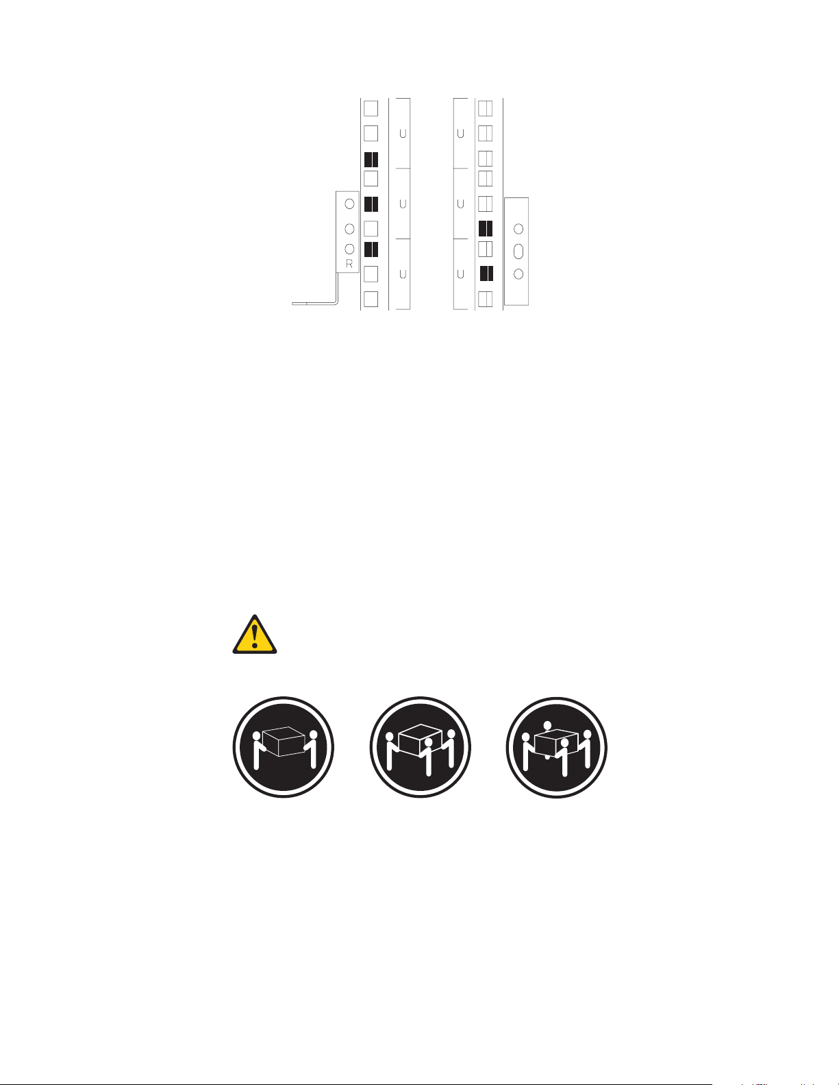
Use the rack-mounting template that comes with the expansion unit to locate the rackmounting holes and install the unit in a rack cabinet. If you do not have the template,
you can use the following steps to install your expansion unit:
1. Use the following illustration of the front and rear rack mounting flanges to
determine the appropriate rack-m o unting ho les for insta lling cage nut s or clip
nuts to s e cu re the Netfinity EXP300 rails. From l e ft to right, the illustration shows
the front and rear flanges respectively.
26 IBM Netfinity EXP300 - Type 3531 Hardware Maintenance Manual
Page 35

Note: Use clip nuts if your rack has round holes. If your rack has square holes,
you can use the rack-inserti on tool or a flat-blade screwdriver to install
cage nut s.
Netfinity EXP300 Type 3531 27
Page 36

2. On the rai l marked R, loose n the four sc rew s Þ2Ýand adjust the rail.
3. Hold the rail against the outside of th e right rack-mounting flange, and loosely
insert th e two front M6 hex scr e ws Þ1Ý.
4. Extend the rail outside of the r e ar rack-mounting fl ange; then, install and tighten
two rear M6 hex screws Þ3Ý.
5. Tighten the two front s cre ws Þ1Ý; then, tighten the four screws Þ2Ý.
Repeat step 2 through step 5 to install the rail marked L on the left side of the rack.
6. Loosely i nsert one M5 screw Þ1Ý into each rail.
28 IBM Netfinity EXP300 - Type 3531 Hardware Maintenance Manual
Page 37

Statement 4
≥18 kg (37 lbs) ≥32 kg (70.5 lbs) ≥55 kg (121.2 lbs)
CAUTION:
Use safe practices when lifting.
7. Slide the expansion unit into the rack, and insert the M6 screws Þ1Ý. Do no t
overtighten the M6 Þ1Ý screws.
8. Tighten the rear screws Þ2Ý.
9. Verify that option switches 1 and 2 (inside the switch card) are set to off (see
“Setting the interface options and ID settings” on page 10 for more information).
10. Install hard disk drives and power supplies in the EXP300 expansion unit
according to “Locations” on page 8; then, return here to complete the installation.
11. Continue with “Completing the installation” on page 35.
Installing the EXP300 in a Tower
The IBM® Netfinity® EXP300 Rack-to-Tower Conversion Kit converts the EXP300
storage expansion unit into a tower mounted installation. You will need a flat-blade
screwdriver and a phillip s screwdriv er to install the EX P30 0. Use the mount ing
hardware that comes with your unit to secure it in the enclosure.
Before installing the expansion unit you mus t:
Netfinity EXP300 Type 3531 29
Page 38

• Review the Safety Information that comes with your EXP300
• Refer to “Locations” on page 8 for removing the switch card, environmenta l
services monitor (ESM) boards, fan and power supply assemblies, and hard
drives to reduce the weight of your EXP300
Note: Th e illust ration s in this docum ent ation mi ght be sligh tly different from your
hardware.
Statement 4
≥18 kg (37 lbs) ≥32 kg (70.5 lbs) ≥55 kg (121.2 lbs)
CAUTION:
Use safe practices when lifting.
1. Loosely i nsert two M5 screws Þ2Ý in the rear of the enclosure; then, turn the
EXP300 counter-clockwise onto its left side and sli de it ful l y in to th e enclosure.
2. Secure the front of the EXP300 with black M6 hex screws Þ1Ý on the top an d
bottom; th e n, tighten the r e ar M5 screws Þ2Ý to secure the back of the EXP300.
30 IBM Netfinity EXP300 - Type 3531 Hardware Maintenance Manual
Page 39

3. Unlock the door Þ3Ý and hold it at a 90 degree angl e to the front of the enclosure;
then, lo we r the top of the door over the tab Þ1Ý on the top of th e e nc losure.
4. Push the bottom of the door until it snaps into place over the ta b Þ2Ý on the
bottom of the enclosure.
5. Verify the settings for internal Option Switch 1 and internal Option Switch 2 on
the swit ch card.
Internal Option Switch 1 defines hard drive enumeration as either left-to-right
(Off ) or top -to-bottom (On). Internal Option Switch 2 swaps the operation of the
genera l system error in dicator with the power-on indicator. Both switche s must
be set to On when a new expansion unit is placed in a tower.
Attention: A loss of data can occur if you change the position of internal Option
Switch 1 or in te rnal Option Switch 3 afte r storing data on the hard drives. Refer
to “Conv e rsion of EXP300 to a tower or from a tower” on page 25 if you
previou sly stored data on the drives and you now want to change the
configuration of your expansio n unit from a rack to a tower orientation.
6. Install the components in the EXP300 that you removed
Installing identification labels
The EXP300 Rack-to-Tower Conversion Kit comes with SCSI ID labels for rack and
tower orientations. This kit also includes expansion unit ID labels for tower
orientations.
To install the identific ation la be ls:
1. Install the SCSI ID label:
The internal Option Switch 3 on the switch card determines whether you have a
single-bus (Off) or dual-bus (On) configuration. When internal Option Switch 3 is
set to Off , al l 14 driv e bay s are on a singl e SCS I bus. Whe n inter nal Option Switc h
3 is set to On, two independent internal seven drive SCSI buses are created.
External SCSI Bus 1 maps to internal SCSI Bus 1 and external SCSI Bus 2 maps to
internal SCSI Bu s 2. The E XP300 assi gns th e seven i nter nal Bus-1 ba ys to S CSI IDs
Netfinity EXP300 Type 3531 31
Page 40

8, 9, 10, 11, 12, 13, and 14; and the seven inte rn al Bus-2 bays to SCSI IDs 0,
1, 2, 3, 4, 5, and 6
Attention: A loss of data can occur if you change the position of internal Option
Switch 1 or in te rnal Option Switch 3 afte r storing data on the hard drives. Refer
to “Conv e rsion of EXP300 to a tower or from a tower” on page 25 if you
previou sly stored data on the drives and you now want to change the
configuration of your expansio n unit from a rack to a tower orientation.
a. Verify the setting of i nternal Option Switch 3 and refer to the appropriate
illustration:
Dual-bus Tower Mode (Switch 3 On) Switch 1 and
Switch 2 On
0
1
2
3
4
5
6
2
1
8
9
10
11
Serial number label
SCSI ID label
Single-bus Tower Mode (Switch 3 Off) Switch 1
and Swi tch 2 On
Serial number label
0
1
2
3
4
5
6
SCSI ID label
8
9
10
11
12
13
14
Expansion unit
ID label
12
13
14
Expansion unit
ID label
b. Locate the SCSI ID label for your configuration. Use the single-bus label if
you set internal Option Switch 3 to the Off position; oth e rwise, use the dualbus label.
c. Orient th e label so that the printed numbers are l e gible from top-to-bottom;
then, peel the backing away from the adhesive side of the label.
d. Carefull y butt the edge of the ID label up against the edge of the serial
number label so that the 14 printed ID numbers are located to the right of
each of the drive b a ys.
e. Apply the labe l to the front of the u nit as shown.
2. Install the expansion unit ID label:
32 IBM Netfinity EXP300 - Type 3531 Hardware Maintenance Manual
Page 41

a. Verify the setting of the unit ID switch (someti me s referred to as a box ID or a
tray ID).
b. Locate the expa nsion unit ID labels that come with thi s ki t; then, apply the
label that matches the setting for the unit ID in the blank label area directly
below the SCSI ID label.
3. Refer to “Turning the expansion unit on and off” on page 3 for information about
turning on the expansion unit.
Note: Important information for IB M Se rveR AID users:
If you are using a ServeRAID software version earlier than Version 3.50, the
View Configuration screens might show SCSI IDs or bay numbers. If the data
shown on the View Configura tion scr een begin s with ' 0', it denote s SCSI IDs.
If the data shown on the V i ew Confi gur ation scree n begin s with '1', it denot es
bay numbers.
Installing the EXP300 in a NetBAY enclosure
NetBAY enclosures are stackable and each can store a diffe rent device, such as the
EXP300 expansion uni t. You also can attach a server to the top of the enclosure. Refer
to the NetBAY documentation for details on installing other devices.
Note: Because of the depth of the NetBAY3 enclosure, it might be difficult to set the
expansion unit option switches once installed. Verify that internal option
switches 1 and 2 are set to Off, and that internal option switch 3 and the Unit
ID dial ID switch are set properly for your environment (see “Setting the
interface options and ID settings” on page 10 for more information).
To install the expansion unit in the enclosure, use the following procedure:
1. Remove the r e ar of the enclosure Þ1Ý.
2. Use the following illustr ation of the front and rear rack-mounting f langes to
determine the appropriate enclo sure-mo unt ing hole s for installing cage nuts to
secure your device and rails. From left to right, the illustration shows the front
and rear flanges respectively.
Netfinity EXP300 Type 3531 33
Page 42
Front Rear
3. On the rai l marked L, loosen the four screws Þ3Ý.
4. Hold the rail ag ainst the outside of the left enclosure-moun ting flange, and
loosely in se rt the two M6 hex screws Þ4Ý.
5. Extend the rail outside of the r e ar e nclosure mounting flange; then, install and
tighten the two rear M6 hex screws Þ5Ý.
6. Tighten the two front he x screws Þ4Ý; then, tighten the four screws Þ3Ý.
Repeat step 3 through step 5 to install the rail marked R on the right side of the
enclosure.
7. Loosely in se rt an M5 screwÞ2Ýinto each rail.
Statement 4
≥18 kg (37 lbs) ≥32 kg (70.5 lbs) ≥55 kg (121.2 lbs)
CAUTION:
Use safe practices when lifting.
8. Slide the expansion unit into the enclosure.
9. Insert tw o M6 screws Þ6Ý, and tighten the M5 sc rews Þ2Ý.
10. Install hard disk drives and power supplies in the EXP300 expansion unit
according to “Locations” on page 8; then, continue with “Completing the
install ation” on page 35.
34 IBM Netfinity EXP300 - Type 3531 Hardware Maintenance Manual
Page 43
Completing the installation
After you install the hard disk drives and power supplies, follow the instructions in
this section to complete the installatio n. Instructio ns for insta lling the identifica tion
labels and cabling the expansion unit are included.
Installing identification labels
Your expansion unit comes with one sheet of 10 labels (0-9) and one sheet of 4 labels
(SCSI ID) labels.
Note: If you are installing the EXP300 expansion unit in a tower , refer to the
information provided wi th the Rack-to-Tower Conversion Kit to set the
option switches and install the SCSI ID labels.
Complete the following steps to install the SCSI identification labels:
To install the label:
1. Locate the SCSI ID label for your configuration.
Note: For a dual-bus configuration, the SCSI ID label includes an arro w with a 1
and a 2 pointing to each bus. Use the single- bus label if internal opt ion
switch 3 is set to Off. Use the dual-b u s label if internal opti on switch 3 is
set to On.
a. Orient th e label so that the pri nted numbers are l egible from left-to-right.
b. Peel the back ing away from the adh e sive side of the label.
c. Carefully butt the edge of the SCSI ID label up against the edge of the serial
number label so that the 14 printed ID numbers are located beneath each of
the drive bays.
d. Apply the label to the front of the unit, as shown in the following illustrations.
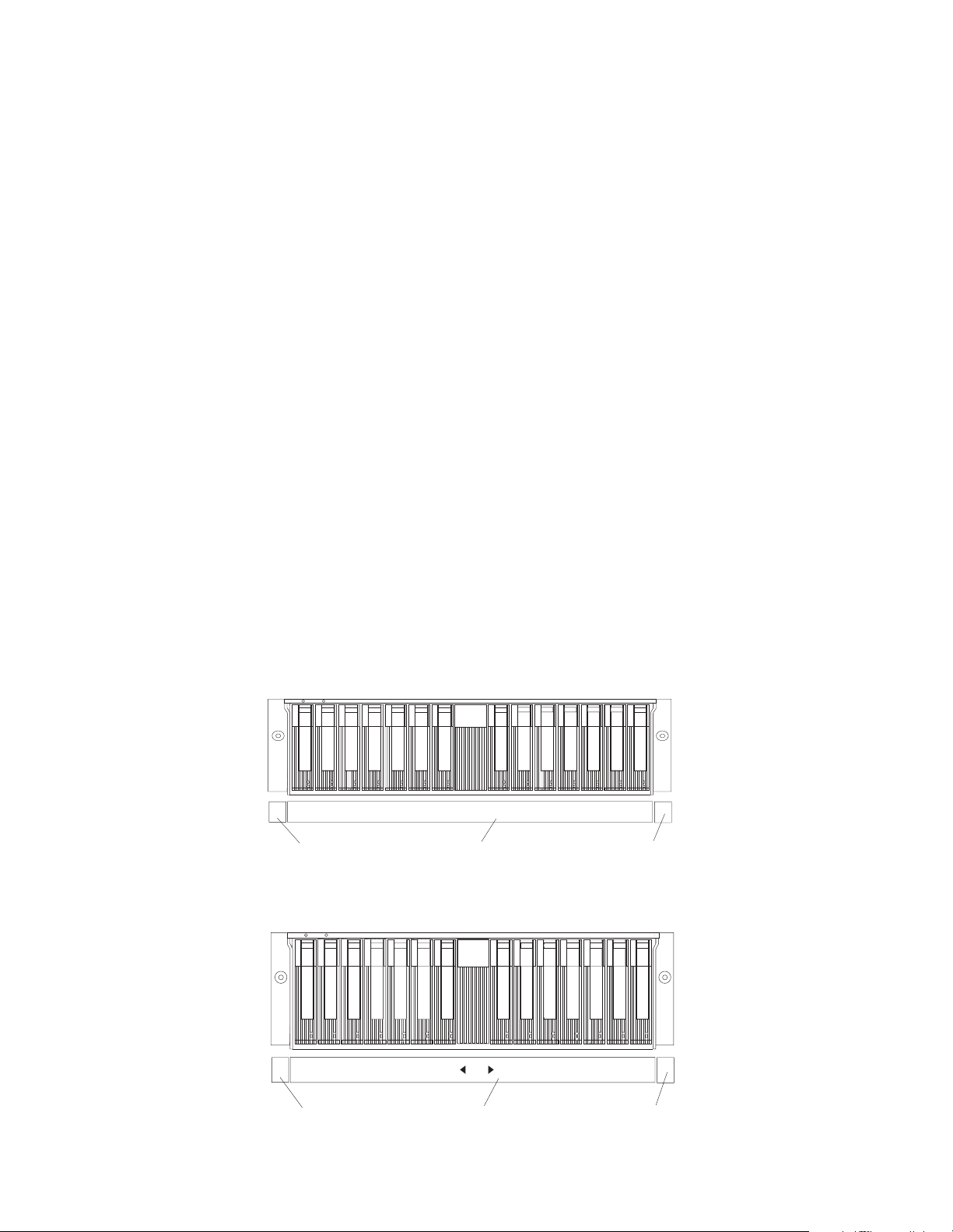
Single-bus configuration
0
12
Expansion unit ID label
3
5
4
69810
SCSI ID label
13
11 12
Serial number label
14
Dual-bus configuration
0
1234
Expansion unit ID label
Netfinity EXP300 Type 3531 35
5
69810
SCSI ID label
13
11 121 2
Serial number label
14
Page 44

2. Install the expansion unit ID label.
a. Verify the setting of the expansion unit number switch (0- 9 ) .
b. Apply the expansion unit ID label that matches the setting for the unit ID
switch in the blank label area directly to the left of the SCSI ID label.
3. Continue with “Cabling the expansion unit”.
Cabling the expansion unit
This section provides the SCSI and power cabling information. After you attach your
SCSI and power cables, use the instructions provided in “Turning the expansion unit
on and off” on p age 3 for the initial startup of the expansion unit.
SCSI cabling information: The IBM Netfinity EXP3 00 comes with two ESM boards.
There are two 68-pin SCSI Very High Density Connector Interface (VHDCI)
connectors. From left to right as seen from the back, these connectors are for SCSI bus
2 and SCSI bus 1. (See “Rear controls, indicat ors, and connectors” on page 15 for the
location of these connectors.) There are three ways to configure these buses .
Attention: A loss of data can occur if you change the position of internal switch 1 or
internal switch 3 after storing data on the drives. Refer to “Con ve rsion of EXP300 to a
tower or f rom a tow er” on page 25 i f you prev iou sly st or ed d ata o n the drives and you
now wan t to ch a ng e the configu ra tion of your exp a n s ion unit from a ra ck to a tower
orientation.
• To configure each bus independently:
1. Verify that option sw itch 3 (in sid e the switc h card) is set to On. ( See “Setti ng
the interface options and ID settings” on page 10 for more informatio n. )
2. Attach one external SCSI cable from the controller in the server to the SCSIbus 1 connector.
3. Attach a second external SCSI cable from the contr oller in the server to the
SCSI-bus 2 connector.
• To configure the expansion unit as a single 14-drive SCSI bus:
1. Verify that Option Switch 3 (inside the switch card) is set to Off. (See
“Setting the interface options and ID settings” on page 10 for more
information.)
2. Attach one external SCSI cable from the controller in the server to either
SCSI-bus connector.
• To configure the expansion unit as a cluster of 13 drives on a single SCSI bus
when using IBM ServeRAID controllers:
Note: When cluste r i ng wit h IB M S e rveRAID ad a p te r s, yo u mu s t configure all
13 disk drives on a single SCSI bus. The driv e bay with SCSI ID =6 is
automatically disabled to avoid an ID conflic t with one of the
ServeRAID controllers.
1. Verify that internal option switch 3 is set to Off. (See “Setting th e interface
options and I D settings” on page 10 for more information.)
2. Attach one external SCSI cable from the controller in server 1 to the SCSIbus 1 connector.
3. Verify that the drive bay with SCSI ID=6 contains a filler panel.
4. Verify that one of the Serv e RAID controller s is set to SCSI ID=6.
5. Attach a second external SCSI cable from the controller in server 2 to the
SCSI-bus 2 connector.
36 IBM Netfinity EXP300 - Type 3531 Hardware Maintenance Manual
Page 45

Parts Listing
SCSI cable restriction: The SCSI controller inside your server must have a dedicated
SCSI channel for the expansion unit. If an external channel is being used for the
expansion unit, its corr espond i ng intern al channel must not be used for other devices.
Power cabling: The expansion unit uses two or four power cords, depending on your
country. You can connect the power cords to a primary power unit inside the rack,
such as a properly grounded ac distribution unit or uninterruptible power supply
(UPS), or to an external source, such as a properly grounded electrical outlet.
Attach the power supply power cords as follows:
1. Connect the power cord to the powe r supply.
2. Plug the power supply cord into a properly grounded electrical outlet.
3. Go to “Turning the expansion unit on and off” on page 3 below for information
about the initial startup of the expansion unit .
1
8
7
4
2
3
6
5
System
Index System (Netfinity EXP300 – Type 3531) FRU No.
1 Filler Panel assembly 00N7259
2 Bridge card assembly 19K1172
Netfinity EXP300 Type 3531 37
Page 46

Index System (Netfinity EXP300 – Type 3531) FRU No.
3 Front bezel 19K1168
4 Switch car d ass e mbl y 19K1173
5 ESM card assembly 19K1171
6 Power supply unit 07K5985
7 Rail kit, left/right 19K1169
8 Midplane/Frame, EXP300 chass is 19K1170
Miscellaneous hardware kit, contains: 19K1174
• Label - Expans ion Unit ID
• Label - Expansion unit ID for tower
• Label - rack/tower SCSI ID
• Light pipe (1)
• Bridge ca rd co ve r (1)
• M6 rail screws (2)
• M6 Nut clips (2)
• M6 Cage Nut (2)
• Screw, M5x8L, SL Flat HD (2)
• Screw, Slotte d M5 (2)
Line cord 6952300
Line cord jumper, high voltage 36L8886
Tower enclosure 19K1184
Tower feet (4) 09N7269
Tower lock/pawl/latch asm (1) 19K1186
Tower front cover assembly 19K1223
Options:
2 M LVD Cable 09N7276
4 M LVD Cable 09N7278
20 M LVD Cable 09N7282
9.1 GB 7200 rpm SCSI Hard Disk Drive 37L6212
18.2 GB 7200 rpm SCSI Hard Disk Drive 37L6213
9.1 GB Ultra160 SCSI Hard Disk Drive 19K0610
18.2 GB Ultra160 SCSI Hard Disk Drive 19K0611
36.4 GB Ultra160 SCSI Hard Disk Drive 19K0612
9.1 GB 10K rpm Ultra2 SCSI Hard Disk Drive 37L6216
18.2 GB 10K rpm Ultra2 SCSI Hard Disk Drive 37L6217
9.1 GB 10K rpm Ultra160 SCSI Hard Disk Drive 19K0613
38 IBM Netfinity EXP300 - Type 3531 Hardware Maintenance Manual
Page 47

Index System (Netfinity EXP300 – Type 3531) FRU No.
18.2 GB 10K rpm Ultra160 SCSI Hard Disk Drive 19K0614
36.4 GB 10K rpm Ultra160 SCSI Hard Disk Drive 19K0615
EXP300 Rack-to-Tower Conversion Kit 09N7296
Power Cords
IBM power cord part
number
13F9940 Argentina, Austral ia, China (PRC), New Zealand, Papua New Guinea, Paraguay,
Uruguay, Western Samoa
13F9979 Afghanistan, Alger ia, Andorra, Angola, Austria, Belgium, Benin, Bulgar ia, Burkina
Faso, Burundi, Cameroon, Central African Rep., Chad, Czech Republic, Egypt,
Finland, France, French Guiana, Germany, Greece, Guinea, Hungary, Iceland,
Indonesia, Iran, Ivory Coast, Jordan, Lebanon, Luxembourg, Macau, Malagasy,
Mali, Martinique, Mauritania, Mauritius, Monaco, Morocco, Mozambique,
Netherlands, New Caledonia, Niger, Norway, Poland, Portugal, Romania, Senegal,
Slovakia, Spain, Sudan, Sweden, Syria, Togo, Tunisia, Turkey, former USSR,
Vietnam, former Yugoslavia, Zaire, Zimbabwe
13F9997 Denmark
14F0015 Bangladesh, Burma, Pakistan, South Africa, Sri Lanka
14F0033 Antigua, Bahrain, Brunei, Channel Islands, Cyprus, Dubai, Fiji, Ghana, Hong
Kong, India, Iraq, Ireland, Kenya, Kuwait, Malawi, Malaysia, Malta, Nepal,
Nigeria, Polynesia, Qatar, Sierra Leone, Singapore, Tanzania, Uganda, United
Kingdom, Yemen, Zambia
14F0051 Liechtenstein, Switzerland
14F0069 Chile, Ethiopia, Italy, Libya, Somalia
14F0087 Israel
Used in these countries and regions
1838574 Thailand
6952300 Bahamas, Barbados, Bermuda, Bolivia, Bra zil, Canad a, Cayman Isl ands, Colombia,
Costa Rica, Dominican Republic, Ecuador, El Salvador, Guatemala, Guyana, Haiti,
Honduras, Jamaica, Japan, Korea (South), Liberia, Mexico, Netherlands Antilles,
Nicaragua, Panama, Peru, Philippine s, Sau di Arabia, Suriname, Taiwan, Trinid ad
(West Indies), United States of America, Venezuela
Netfinity EXP300 Type 3531 39
Page 48

40 IBM Netfinity EXP300 - Type 3531 Hardware Maintenance Manual
Page 49

Chapter 2. Related service information
Note: The service procedures are designed to help you isolate problems. They are
writte n with the assumption th at you have model-specific training on all
computers, or that are familiar with the computers, functions, terminology,
and service information provided in this manual.
Safety information
The following section contains the safety information that you need to be familiar
with before servicing an IBM computer.
General saf et y
Follow these rules to ensure general safety:
• Observe good housekeeping in the area of the machines during and after
maintenance.
• When lifting any heavy object:
1. Ensure you can stand safely without slipping.
2. Distribute the weight of th e o b je ct equally between your feet.
3. Use a slow lifting force. Never move suddenly or twist when you attempt to
lift.
4. Lift by standing or by pushing up wi th your leg muscles; this action
remov e s the strain from the muscles in your back . Do not attempt to lift any
objects that weigh more than 16 kg (35 lb) or obj ects that you think ar e too heavy for
you.
• Do not perform any action that causes hazards to the customer, or that makes
the equipment unsafe.
• Before you start the machine, ensure that other service repr esentatives and the
customer's personnel are not in a hazardous position.
• Place removed covers and other parts in a safe place, away from all personnel,
while you are servicing the machine.
• Keep your tool case away from walk areas so that other people will not trip over
it.
• Do not wear loose cloth ing that can be trapped in the moving par ts of a machine.
Ensure that your sleeves are fastened or rolled up above your elb ows. If your
hair is long, fasten it.
• Insert the ends of your necktie or scarf inside clothing or fasten i t with a
nonconductive clip, approximately 8 centimeters (3 inches) from the end.
• Do not wear jewelry, chains, metal-frame eyeg lasses, or meta l fasteners for your
clothin g .
Remember: Metal objects are good electrical conductors.
• Wea r safety glasses when you are: hammering, drilling soldering, cutting wire,
attachi ng springs, using solvents, or work ing in any other con ditions that mig ht
be hazardous to your eyes.
© Copyright IBM Corp. 2000 41
Page 50

• After service, reinstall all safety shields, guards, labels, and ground wires.
Replace any safety device that is worn or defective.
• Reinstall all covers correctly before returning the machine to the customer.
Electrical safety
CAUTION:
Electrical c urrent from power, telephone, and co mmunication cables can be
hazardous. To avoid personal injury or equ ipment damage, dis connect th e attac hed
power cor d s, te lec o mm unication sy ste m s, net w o rk s, and modems befo re y ou o pe n
the server covers, unless instructed otherwise in the installation and configuration
procedures.
Observe the following rules when working on electrical equipment.
Important : Use only approved tools and test equipment. Some hand tools have
• Find the room emergency power-off (EPO) switch, disconnecting switch, or
electrical outlet. If an el ectri cal accident occurs, you can then operate the switch
or unplug the power cord quickly.
• Do not work alone under hazardous conditions or near equipment that has
hazardous voltages.
• Disconnect all power before:
— Performing a mechanical inspection
— Working near power supplies
— Remov ing or installing main units
• Before you start to work on the machine, unplug the power cord. If you cannot
unplug it, ask the customer to power-off the wall box that supplies power to the
machin e and to lock the wall box in the off position.
• If you need to work on a machine that has e xposed electri cal cir cuits, observe the
following precautions:
— Ensure that another person, familiar with the power-off controls, is near
you.
Remember: Another per son must be there to switch off the power, if
necessary.
— Use only one hand when working with powered-on electri cal equipment;
keep the other hand in your pocket or behind your back.
Remember: There must be a co mplete circ ui t to ca u s e ele ct r i ca l shock. By
observing the above rule, you may prevent a current from passing through
your body.
— When using testers, set the controls correctly and use the approved probe
leads and accessories for that te ster.
— Stand on suitable rubber mats (obtained locally, if necessary) to insulate you
from grounds such as metal floor strips and machine frames.
handles covered with a s of t material that does not insulate you when
working with live electrical currents.
Many customers have, near their equipment, rubber floor mats that
contain small conductive fibers to decrease electrostatic discharges.
Do not use this ty p e of mat to protect yours e lf from electrical shock.
42 IBM Netfinity EXP300 - Type 3531 Hardware Maintenance Manual
Page 51

Observe the special safety precautions when you work with very high voltages;
these instructions are in the safety sections of maintenance information. Use
extreme care when measuring high voltages.
• Regularly inspect and maintain your electrical hand tools for safe operational
condition.
• Do not use worn or broken tools and testers.
• Neve r assume that power has b e en disconnected from a cir cu it. First, check that it
has been po we red-off.
• Always look car efully for pos sible hazard s in your work ar ea. Examples of th ese
hazards are moist floors, nongrounded power extension cables, power surges,
and mi ss i ng sa f e t y gro u nds.
• Do not touch live electrical circuits with the reflective sur f ace of a plastic dental
mirror. The surfac e is conductive ; such touch in g ca n ca u s e per sonal injury a nd
machine damage.
• Do not service the following parts with the power on when they ar e removed
from their normal operating places in a machine:
— Power supply units
—Pumps
—Blowers and fans
— Motor generators
and simil a r units. (This practice ensures c orrect grounding of the units.)
• If an electrical accide nt occ urs:
— Use caution; do not become a victim yourself.
—Switch off power.
— Send another person to get medical aid.
Safety inspection guide
The intent of this inspection guide is to assist you in identifying potentially unsafe
conditions on these products. Each machine, as it was designed and built, had
required s afety items installed to prot ect users a nd service perso nnel fr om injury. This
guide addresses only those items. However, good judgment should be used to
identify pot enti al sa fe ty haza r ds d ue to att ach ment of n on-I BM features or option s no t
covered by this inspection guide.
If any unsafe conditions are present, you must determine how serious the apparent
hazard could be and whether you can continue without f irst corre cting the proble m.
Consider these conditions and the safety hazards they present:
• Electrical hazards, especiall y primary power (primary voltage on the frame can
cause serious or fatal electr ical shock).
• Explosive hazards, such as a damaged CRT face or bulging capacitor
• Mechanical hazards, such as loose or missing hardwar e
The guide consists of a series of steps presented in a checklist. Begin the checks with
the power off, and the power cord disconnected.
Checklist:
Chapter 2. Related service information 43
Page 52

1. Check exterior covers for damage (loose, broken, or sharp edges).
2. Power-off the computer. Disconnect the power cord.
3. Check the power cord for:
a. A third- wire groun d connector in good con di tion. Use a meter to measure
thir d-wire ground continuity for 0.1 ohm or less between t he external ground
pin and frame ground.
b. The power cord should be the appropriate type as specified in the parts
listings.
c. Insulation must not be frayed or worn.
4. Remove the cover.
5. Check for any obvious non-IBM alterations. Use good judgment as to the safety
of any non-IBM alterations.
6. Check inside the unit for any obv ious unsafe cond itions , su ch as metal filings ,
contamination, water or other liquids, or signs of fire or smoke damage.
7. Check for worn, frayed, or pinched cables.
8. Check that the power-supp ly cover fastener s ( screws or rive ts) have not been
removed or tampered with.
Handling electrostatic discharge-sensitive devices
Any computer part containing transistors or integrated circuits (ICs) should be
considered sensitive to electrostatic discharge (ESD). ESD damage can occur when
there is a difference in charge between objects. Protect against ESD damage by
equalizing the charge so that the machine, the part, the work mat, and the person
handling the part are all at the same charge.
Notes:
1. Use product-specific ESD procedures when they exceed the requir ements noted
here.
2. Make sure that the ESD protective devices you use have been certified (ISO 9000)
as fully effective.
When handling ESD-sensitive parts:
• Keep the parts in protective packages until they are inserted into the product.
• Avoid contact with other people.
• Wear a grounded wrist strap against your skin to eliminate static on your body.
• Prevent the part from touching your clothing. Most clothin g is insulative and
retains a charge even when you are wearing a wrist strap.
• Use the black side of a grounded work mat to provide a static-fr ee work surfac e.
The mat is especially useful when handling ESD-sensitive devices.
• Select a grounding system, such as those l isted below, to provide protection that
meets the specific service requirement .
Note: The use of a grounding system is desirable but not required to protect
against ESD damage.
— Attach the ESD ground clip to any frame ground, ground braid, or green-
wire ground.
— Use an ESD common ground or reference point when working on a double-
insulated or battery-operated system. You can use coax or connectoroutside shel ls on these systems.
44 IBM Netfinity EXP300 - Type 3531 Hardware Maintenance Manual
Page 53

— Use the round ground-prong of the ac plug on ac-operated computers.
Grounding require m ents
Electrical grounding of the computer is required for operator safety and correct
system fun ction. Proper grounding of the electrical outlet can be verified by a
certified electrician.
Safety notices (multi-lingual translations)
The caution and danger safety notices in this section ar e p rovided in the following
languages:
• English
• Brazilian /Portuguese
•Chinese
•French
•German
• Italian
•Korean
•Spanish
Important: All caution and danger statement s in this section begin with a
number. This number is u s e d to cross r eference an E nglish caution or
danger stateme n t w i th translate d version s of th e ca u t i o n or danger
statement i n this section.
For example, if a caution statement begins with a number 1,
translations for that caution statement appear in this section under
statement 1.
Be sure to read all caution and danger statements before performing
any of the inst ructions.
•Statement 1
DANGER
Electrical current from power, telephone and communication cables is hazardous.
To avoid a shock hazard:
• Do not connect or disconnect any cables or perform installation, maintenance,
or reconfiguration of this product during an electrical storm.
• Connect all power cords to a properly wired and grounded electrical outlet .
• Connect to properly wired outlets any equipment that will be attached to this
product.
• When pos si ble , use one han d onl y to co nn ec t or dis connect signal cables.
• Never turn on any equipment when there is evidence of fire, water, or
structu r a l dam a ge .
Chapter 2. Related service information 45
Page 54

• Disconnect the attached power cords, telecommunications systems, networks,
and modems before you open the device covers, unless instructed otherwise
in the installation and configuration procedures.
• Conne ct an d di sc onnect cables as described in the follo wi n g table wh en
installing, moving, or opening covers on this product or attached devices.
To Connect To Disconnect
1. Turn everything
OFF.
2. First, attach all
cables to devices.
3. Attach signal
cables to
connectors.
4. Attach power
cords to outlet.
5. Turn device ON .
•Statement 2
CAUTION:
When replacing the lithium battery, use only IBM Part Number 33F8354 or an
equivalent type battery recommended by the manufacturer. If your system has a
module containing a lithium battery, replace it only with the same module type
made by the same manufacturer. The battery contains lithium and can explode if
not properly us ed, handl e d, or disposed of.
1. Turn everything
OFF.
2. First, remove
power cords from
outlet.
3. Remove sig nal
cables from
connectors.
4. Remove all cables
from devices.
Do not:
• Throw or immerse into water
• Heat to more than 100°C (212°F)
• Repair or disassemble
Dispose of the battery as required by local ordinances or regulations.
•Statement 3
CAUTION:
When laser products (such as CD-ROMs, DVD-ROM drives, fiber optic devices, or
transmitters) are installed, note the following:
• Do not remove the covers. Removing the covers of the laser product could
result in exposure to hazardous laser radiation. There are no serviceable parts
inside the device.
• Use of controls or adjustments or performance of procedures other than those
specified herein might result in hazardous radiation exposure.
46 IBM Netfinity EXP300 - Type 3531 Hardware Maintenance Manual
Page 55

DANGER
1
2
Some laser products contain an embedded Class 3A or Class 3B laser diode. Note
the following:
Laser radiation when open. Do not stare into the beam, do not view directly with
optical instruments, and avoid direct exposure to the beam.
•Statement 4
≥18 kg (37 lbs) ≥32 kg (70.5 lbs) ≥55 kg (121.2
lbs)
CAUTION:
Use safe practices when lifting.
•Statement 5
CAUTION:
The power control button on the device and the power switch on the power supply
do not turn off the electrical current supplied to the device. The device also might
have more than one power cord. To remove all electrical current from the device,
ensure that all power cords are disconnected from the power source.
•Statement 10
CAUTION:
Chapter 2. Related service information 47
Page 56

Do not place any object weighing more tha n 82 kg (180 lb s.) on top of rac k-mounted
device s.
48 IBM Netfinity EXP300 - Type 3531 Hardware Maintenance Manual
Page 57

Importante:
Todas as instruções de cuidado e perigo da Netfinity Server Library começam com um
número. Este número é utilizado para fazer referência cruzada de uma instrução de
cuidado ou perigo no idioma inglês com as versões traduz idas das instru çõe s de
cuidado ou peri g o e nc on tradas nesta seção.
Por exemplo, se um a instrução de cuidado é iniciada com o númer o 1 , as traduções
para aquela instrução de cuidad o a p arecem nesta seção sob a i nstrução 1.
Certifique-se de ler todas as in struções de cuidado e per igo antes de executar
qualquer operação.
Instrução 1
PERIGO
A corrente elétrica provenien te de cabos de alimentação, de telefone e de
comunicações é perigosa.
Para evitar risco de choque :
• Não conecte ou desconecte cabos e não re alize instalação, manutenção ou
reconfiguração deste produto durante uma tempestade com raios.
• Conecte todos os cabos de alimenta ção a tomadas elétricas corretamente
instaladas e aterradas.
• Conecte todos os equipamentos ao qual e sse p roduto será conec tado a tomadas
corretamente instaladas.
• Sempre que possível, utilize apenas uma das mãos para conectar ou desconectar
cabos de sinal.
• Nunca ligue qualquer equipamento quando existir evidência de danos por fogo,
água ou na estrutura.
• Descone ct e ca bos d e al i mentaç ão, si st emas de t e lecom uni c ação , r e des e mod ems
antes de abrir as tampas dos dispositivos, a menos que especificado de maneira
diferente nos procedimentos de instalação e configuração.
• Conecte e desconecte cabos conforme descrito na seguinte tabela, ao instalar ou
movimentar este produto ou os dispositivos conectados, ou ao abrir suas
tampas.
Chapter 2. Related service information 49
Page 58

Para Conectar: Para Desconectar:
1. DESLIGUE Tu do.
2. Primeiramente,
conecte todos os
cabos a os
dispositivos.
3. Conecte os cabos
de sinal aos
conectores.
4. Conecte os cabos
de alimentação às
tomadas.
5. LIGUE os
disposi tivos.
Instrução 2
CUIDADO:
Ao substituir a bateria de líti o, utilize apenas uma bateria IBM, Número de Peça
33F8354 ou uma bateria de tipo equivalente, recomendada pelo fabricante. Se o seu
sistema possui um móídulo com uma bateria de lítio, substitua-o apenas pelo mesmo
tipo de míd ulo, d o me smo fab ric ante. A b ater ia c onté m lít i o e po de ex pl odir se não for
utilizada, manuseada e descartada de maneira correta.
1. DESLIGUE Tudo.
2. Primeiramente,
remova os cabos
de alimentação
das tomadas.
3. Remova os cabos
de sinal dos
conectores.
4. Remova todos os
cabos dos
disposit iv os.
Não:
• Jogue ou coloque na água
• Aqueça a mais de 100°C (212°F)
• Conserte nem desmonte
Para descartar a bateria, ent re em contato com a área de atendimento a clientes IBM,
pelo telefone (011) 889-8986, para obter informações sobre como enviar a bateria pelo
correio para a IBM.
Instrução 3
PRECAUCIÓN:
Quando pr odutos a laser (unid a des de CD-ROM, unidades de DVD, dispositi vos de
fibra íti ca, transmissore s, etc.) estiverem instalados, observe o seguinte:
• Não remova as tampas. A remoção das tamp as de um produto a laser pode
resultar em exposição prejudicial à radiação de laser. Nenhuma peça localizada
no interior do dispositivo pode ser consertada.
• A utilização de controles ou ajustes ou a execução de procedimentos diferentes
dos especificados aqui pode resultar em exposição prejudicial à radiação.
50 IBM Netfinity EXP300 - Type 3531 Hardware Maintenance Manual
Page 59

PERIGO
1
2
Alguns produtos a laser contêm um diodo laser da
Classe 3A ou Classe 3B embutido. Observe o seguinte:
Radiação de lase r quando aberto. Não ol he diretamente para o raio a olho nu ou com
instrumentos íticos, e evite exposição direta ao raio.
Instrução 4
≥18 kg (37 lbs) ≥32 kg (70,5 lbs) ≥55 kg (121,2
lbs)
CUIDADO:
Ao levantar a máquina, faça-o com segurança.
Instrução 5
CUIDADO:
Os botões Liga/Desliga localizados no dispositivo e na fonte de alimentação não
desligam a corrente elétrica fornecida ao dispositivo. O dispositivo também pode ter
mais de um cabo de alimentação. Para remover toda a corrente elétrica do dispositivo,
assegur e que todos os cabos de alimen tação estejam desconectados da fonte de
energia elétrica.
CUIDADO:
Instrução 10
CUIDADO:
Chapter 2. Related service information 51
Page 60

Não coloque nenhum objeto com peso superior a 82 kg (180 l bs.) sobre dispositivos
montados em rac k.
52 IBM Netfinity EXP300 - Type 3531 Hardware Maintenance Manual
Page 61

Chapter 2. Related service information 53
Page 62

54 IBM Netfinity EXP300 - Type 3531 Hardware Maintenance Manual
Page 63
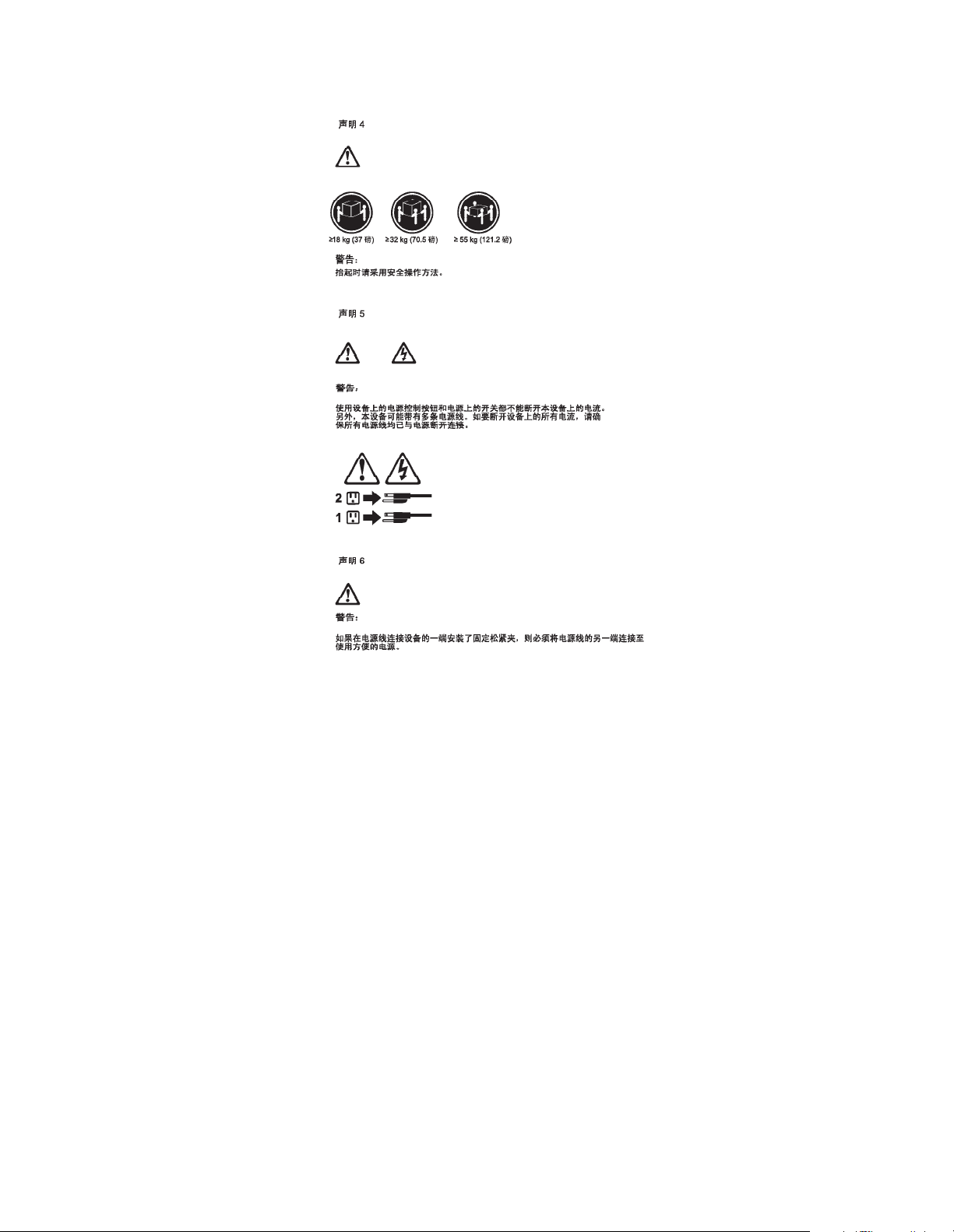
Chapter 2. Related service information 55
Page 64

56 IBM Netfinity EXP300 - Type 3531 Hardware Maintenance Manual
Page 65

Chapter 2. Related service information 57
Page 66

58 IBM Netfinity EXP300 - Type 3531 Hardware Maintenance Manual
Page 67

Chapter 2. Related service information 59
Page 68

60 IBM Netfinity EXP300 - Type 3531 Hardware Maintenance Manual
Page 69

Important:
Toutes les consignes Attention et Danger indiquées dans la bibliothèque Netfinity
Server sont précédées d'un numéro. Ce dernier permet de mettre en c orr espondance la
consigne en anglais avec ses versions traduites dans la présente sect i on .
Par exemple, si une consigne de type Attention est précédée du chiffre 1, ses
traductions sont également précédées du chiffre 1 dans la présente section.
Prenez connaissance de toutes les consign es de type Attention et Danger avant de
procéder aux opérations décrites par les instructions.
Notice n° 1
DANGER
Le courant électrique passant dans les câbles de communication, ou les cordons
téléphoniques et d'alimentation peut être dangereux.
Pour éviter tout risque de choc électrique:
• Ne manipulez aucun câble et n'effectuez aucune opération d'installation,
d'entretien ou de reconfiguration de ce produit au cours d'un orag e .
• Branchez tous les cordons d'alimentation sur un socle de prise de courant
correcte m e n t câblé et mis à la terre .
• Branchez sur des socles de pr ise de courant correc tement c âblés tout équipement
connecté à ce produit.
• Lorsque cela est possible, n'utilisez qu'une seule main pour connecter ou
déconnecter les câbles d'interface.
• Ne mettez jamais un équipement s ous tension en c as d'inc endie ou d'inondatio n,
ou en présence de dommages matériels.
• Avant de retirer les carters de l'unité, met tez c elle-ci hors tension et déconnectez
ses cordons d'alimentation, ainsi que les câbles qui la relient aux réseaux, aux
systèmes de télécommunication et aux modems (sauf instruction contraire
mentionnée dans les procédures d'inst allatio n et de configurat ion) .
• Lorsque vous installez ou que vous déplacez le présent produit ou des
périphériques qui lui sont raccordés, reportez-vous aux instructions ci-dessous
pour connecter et déconnecter les différents cor dons.
Chapter 2. Related service information 61
Page 70

Connexion Déconnexion
1. Mettez les unités
hors tension.
2. Commencez par
brancher tous les
cordon s su r les
unités.
3. Branchez les
câbles d'interface
sur des
connecteurs.
4. Branchez les
cordons
d'alimentation
sur des prises.
5. Mettez les unité s
sous tension.
Notice n° 2
ATTENTION:
1. Mettez les unités
hors tension.
2. Débranchez les
cordons
d'alimentat ion des
prises.
3. Débranchez les
câbles d'interface
des connecteurs.
4. Débranchez tous
les câbles des
unités.
Remplacez la pile au lithium usagée par une pile de référence identique
exclusive m en t - voir la réf ér en ce IB M - ou pa r un e pile éq uiv al e nte reco mm a nd ée
par le fabricant. Si votre système est doté d'un module contenant une pile au
lithium, vous devez le remplacer uniquement par un module identique, produit
par le même fabricant. La pile contient du lithium et présente donc un risque
d'explosion en cas de mauvaise manipulation ou utilisation.
• Ne la jetez pas à l'eau.
• Ne l'exposez pas à une température supérieure à 100 °C.
• Ne cherchez pas à la réparer ou à la démonter.
Pour la mise au rebut, reportez-vous à la réglementation en vigueur.
Notice n° 3
ATTENTION:
Si des produits laser sont installés (tels que des unités de CD-ROM ou de DVD,
des périphériques contenant des fibres optiques ou des émetteurs-récepteurs),
prenez connaissance des informations suivantes:
• N'ouvrez pas ces produits pour éviter une exposition directe au rayon laser.
Vous ne pouvez effectuer aucune opération de maintenance à l'intérieur.
• Pour éviter tout risque d'exposition au rayon laser, respectez les consignes de
réglage et d'utilisation des commandes, ainsi que les procédures décrites dans
le présent document.
62 IBM Netfinity EXP300 - Type 3531 Hardware Maintenance Manual
Page 71

DANGER
1
2
Certains produits laser contiennent une diode laser de classe 3A ou 3B. Prenez
connaissance des informations suivantes:
Rayonnement laser lorsque le carter est ouvert. évitez de regarder fixement le
faisceau ou de l'observer à l'aide d'instruments optiques. évitez une exposition
directe au rayon.
Notice n° 4
≥18 kg ≥32 kg ≥55 kg
ATTENTION:
Faites- vous aider pour soulever ce produit.
Notice n° 5
ATTENTION:
Le bouton de mise sous tensi on/hors tension de l'unité et l'interrupteur
d'alimentation du bloc d'alimentation ne coupent pas l'arrivée de courant
électrique à l'intérieur de la machine. Il se peut que votre unité dispose de
plusieurs cordons d'alimentation. Pour isoler totalement l'unité du réseau
élect rique, débranchez tous les cor dons d'alimentation des socle s de prise de
courant.
Notice n° 10
Chapter 2. Related service information 63
Page 72

ATTENTION:
Ne posez pas d'objet dont le poids dépasse 82 kg sur les unités montées en armoire.
64 IBM Netfinity EXP300 - Type 3531 Hardware Maintenance Manual
Page 73

Wichtig:
Alle Sicherheitshinwe ise in dieser Netfinity Server-Bibliothek beginnen mit einer
Nummer. Diese Nummer verweist auf einen englischen Sicherheitshinweis mit den
übersetzten Versionen dieses Hinweises in diesem Abschnitt.
Wenn z. B. ein Sicherheitshinweis mit der Nummer 1 beginnt, so erschein t die
übersetzung für diesen Sic herheitshin we is in diesem Abschnitt unter dem Hinweis 1.
Lesen Sie alle Sicherheitshinweise, bevor Sie eine Anweisung ausführen.
Hinwei s 1
VORSICHT
Elektrische Spannungen von Netz-, Telefon- und Datenübertragungsleitungen sind
gefährlich.
Aus Sicherheitsgründen:
• Bei Gewitter an diesem Gerät keine Kabel anschließen oder lösen. Ferner keine
Install a tions-, Wartungs- od e r Rekonfigurationsarbeiten durchführen.
• Gerät nur an eine Schutzkontaktsteckdose mit ordnung sg e mäß geerdetem
Schutzkontakt anschließen .
• Alle angeschlossenen Geräte ebenfalls an Schutzkontaktsteckd ose n mit
ordnungsgemäß geerdetem Schutzkontakt anschließen.
• Signalkabel möglic hst einhändig anschließen oder lösen.
• Keine Geräte einschalten, we nn die Gefahr einer Besch ädigung durch Feuer,
Wasser oder andere Einflüsse besteht.
• Die V erbindung zu den angeschlossenen Netzkabeln,
Telekommunikationssystemen, Netzwerken und Modems ist vor dem öffnen
des Gehäuses zu unterbrechen. Es sei denn, dies ist in den zugehörigen
Install ations- und Konfigurationsprozeduren anders angegeben.
• Nur nach den nachfolgend aufgeführten Anweisungen arbeiten, die für
Install ation , Transport oder öf fne n von Gehä us en von Per sonal Compu tern od er
angeschl ossenen Einheiten gel ten.
Chapter 2. Related service information 65
Page 74

Kabel anschlieβen: Kabel lösen:
1. Alle Geräte
auss chalten u n d
Netzstecke r
ziehen.
2. Zuerst alle Kabel
an Einheiten
anschließen.
3. Signalkabel an
Anschlußbuchse
n anschließen.
4. Netzstecker an
Steckdose
anschließen.
5. Gerät
einschalten.
Hinwei s 2
ACHTUNG:
Eine verbrauchte Batterie nur durch eine Batter i e mit der IBM Teilenummer 33F8354
oder dur ch e ine vom Hersteller empfohlene Batte rie ersetzen. Wenn Ihr System ein
Modul mit einer Lithium-Batterie enthält, ersetzen Sie es immer mit dem selben
Modultyp vom se lben Herstelle r. Die Batterie enthält Lithium und ka nn bei
unsachgemäßer Verwendung, Handhabung oder Entsorgung explodieren.
1. Alle Geräte
ausschalten.
2. Zuerst
Netzstecker von
Steckdose lösen.
3. Signalkabel von
Anschlußbuchsen
lösen.
4. Alle Kabel von
Einheiten lösen.
Die Batterie nicht:
• mit Wasser in Berührung bringen.
• über 100 C erhitzen.
• reparieren oder zerlegen.
Die örtlichen Bestimmungen für die Entsorgung von Sondermüll beachten.
Hinwei s 3
ACHTUNG:
Wenn ein Laserprodukt (z. B. CD-ROM-Laufwerke, DVD-Laufwerke, Einheiten mit
Glasfaserkabe ln ode r Transmitter) installiert ist, beachten Sie folg en des .
• Das Entfernen der Abdeckungen des CD-ROM-Laufwerks kann zu gefährlicher
Laserstrahlung führen. Es befinden sich keine Teile innerhalb des CD-ROMLaufwerks, die vom Benutzer gewartet werden müssen. Die Verkleidung des
CD-ROM-Laufw e rks nicht öffn en.
66 IBM Netfinity EXP300 - Type 3531 Hardware Maintenance Manual
Page 75

• Steuer- und Einstellelemente sowie Verfahren nur entsprechend den
1
2
Anweisungen im vorliegenden Handbuch einsetzen. Andernfalls kann
gefährliche Laserstrahlung au ftreten.
VORSICHT
Manche CD-ROM-Laufw erke enth alten eine ei ngebau te Lase rdiode der Klasse 3A
oder 3B. Die nachfolgend aufgeführten Punkte beachten.
Laserstrahlung bei geöffneter Tür. Niemals direkt in den Laserstrahl sehen, nicht
direkt mit optischen Instrumenten betrachten und den Strahlungsbereich meiden.
Hinwei s 4
≥18 kg ≥32 kg ≥55 kg
ACHTUNG:
Beim Anheben der Maschine die vorgeschriebenen Sicherheitsbestimmungen
beachten.
Hinwei s 5
ACHTUNG:
Mit dem Betri e b ssp annungsschalte r an der Vorderseite des Servers und dem
Betrieb ssp annungsschalter am Netzteil wird die Stromversorgung für den Server
nicht unterbrochen. Der Server könnte auch mehr als ein Netzkabel aufweisen. Um
die gesamte Stromversorgung des Servers auszuschalten, muß sichergestell t werden,
daß alle Netzkabel aus den Netzstec k dosen herausgezogen wu rden.
Hinwei s 10
Chapter 2. Related service information 67
Page 76

ACHTUNG:
Keine Gegenstände, die mehr als 82 kg wiegen, auf Rack-Einheiten ablegen.
68 IBM Netfinity EXP300 - Type 3531 Hardware Maintenance Manual
Page 77

Importante:
Tutti gli avvisi di attenzione e di pericolo riportati nella pubblicazione Netfinity Server
Library iniziano con un numero. Questo numero viene utilizzato per confrontare
avvisi di attenzione o di pericol o in ingl ese c on l e ver sioni tr adotte riportate in questa
sezione.
Ad esempio, se un avviso di attenzione inizia con il numero 1, la relativa versione
tradotta è presente in questa sezione con la stessa numerazione.
Prima di eseguire una qualsiasi istruzione, accertarsi di leggere tutti gli avvisi di
attenzione e di pericolo.
Avviso 1
PERICOLO
La corrente elettrica circ ol ante nei cavi di alimentazion e, del telefo no e di segnale è
pericolosa.
Per evitare il pericolo di scosse elettriche:
• Non collegare o scollegare i cavi, non effettuare l'installazione, la manutenzione
o la riconfigurazione di que sto prodotto duran te i temporali.
• Collegare tutti i cavi di alimentazione ad una presa elettrica correttamente
cablata e munita di terra di sicurezza.
• Collegare qualsiasi apparecchiatura coll e g ata a questo prodotto ad una presa
elettrica correttamente cablata e munita di terr a di si curezza.
• Quando possibile, collegare o scollegare i cavi di segnale con una sola mano.
• Non accendere qualsiasi apparecchiatura in presenza di fuoco, acqua o se sono
presen ti danni all'apparecchiatura stessa.
• Scollegare i cavi di alimentazione, i sistemi di telecomunicazioni, le reti e i
modem prima di aprire i coperchi delle unità, se non diversamente indicato nelle
procedure di installazione e configurazione.
• Collegare e scollegar e i cavi come descritto nel la seguente tabella quando si
effettuano l'installazione, la rimozione o l'apertura dei coperchi di questo
prodot t o o
delle unità collegate.
Chapter 2. Related service information 69
Page 78

Per collegare: Per scollegare:
1. SPEGNERE tutti i
dispositivi.
2. Collegare prima
tutti i cavi alle
unità.
3. Collegare i cavi di
segnale ai
connettori.
4. Collegare i cavi di
alimentazione
alle prese
elettriche.
5. ACCENDERE le
unità.
Avviso 2
ATTENZIONE:
Quando si sostituisce la batteria al litio, utilizzare solo una batteria IBM con numero
parte 33F8354 o batterie dello stesso tipo o di tipo equivalente consigliate dal
produttore. Se il sistema di cui si dispone è prov visto di un modulo cont e nen te una
batteria al litio, sostituire tale batteria solo con un tipo di modulo uguale a quello
fornito dal produttore. La batteria contiene l i tio e può esplodere se utilizzata,
maneggiata o smaltita impropriamente.
1. SPEGNERE tutti i
dispositivi.
2. Rimuovere prima i
cavi di
alimentazione
dalle prese
elettriche.
3. Rimuovere i cavi
di segnale dai
connettori.
4. Rimuover e tu tti i
cavi dalle unità.
Evitare di:
• Gettarl a o immergerla in acqua
• Riscaldarla ad una temperatura superiore ai 100°C
• Cercare di ripararla o smontarla
Smaltire secondo la normativa in vigore (D.Lgs 22 del 5/2/9) e su cc essive
disposizioni nazionali e locali.
Avviso 3
ATTENZIONE:
Quando si installano prodotti laser come, ad esempio, le unità DVD, CD-ROM, a fibre
ottiche o trasmettitori, prestare attenzion e a quan to se gue:
• Non rimuovere i coperchi. L'apertura dei coperchi di pr odott i laser può
determinare l'esposizione a radiazioni laser pericolose. All'interno delle unità
non vi sono parti su cui effettu a re l'assistenza tecnica.
• L'utilizzo di controlli, regolazioni o l'esecuzio ne di proce dure non descritti nel
presente manuale possono provo care l'esposizione a radiazioni pericolose.
70 IBM Netfinity EXP300 - Type 3531 Hardware Maintenance Manual
Page 79

PERICOLO
1
2
Alcuni prodotti laser contengono all’interno un dio do l ase r di Classe 3A o Classe 3B.
Prestare attenzione a quanto segue:
Aprendo l'unità vengono emesse radiazioni laser. Non fissare il fascio, non guardarlo
direttamente con strumenti ottici ed evitare l'esposizione diretta al fasc i o.
Avviso 4
≥18 kg ≥32 kg ≥55 kg
ATTENZIONE:
Durante il sollevamento della mac ch ina seguire delle norme di sicurez za.
Avviso 5
ATTENZIONE:
Il pulsante del controllo dell'alimentazione situato sull'unità e l'interruttore di
alimentazione posto sull'al imentatore non disattiva la corrente elettrica fornita
all'unità. L'unità potrebbe dispor re di più di un cavo di alimentazione. Per disatt ivare
la corrente elettrica dall'unità, accertarsi che tutti i cavi di alimentazione siano
scollegati dalla sorgente di alimentazione.
Avviso 10
Chapter 2. Related service information 71
Page 80

ATTENZIONE:
Non poggiare oggetti che pesano più di 82 kg sulla parte superiore delle unità
montate in rack.
72 IBM Netfinity EXP300 - Type 3531 Hardware Maintenance Manual
Page 81

Chapter 2. Related service information 73
Page 82

74 IBM Netfinity EXP300 - Type 3531 Hardware Maintenance Manual
Page 83

Chapter 2. Related service information 75
Page 84

Important e :
Todas las declaraciones de precauciín de est a Biblioteca del servidor Netfin ity empiezan
con un nú m ero. D icho número s e em p le a para es t a b le ce r un a refe ren cia cru z a da de
una declaraciín de precauciín o peligro en inglés con las versiones traducidas que de
dichas declaraciones pueden encontrarse en esta secciín.
Por ejemplo, si una declaraciín de peligro empieza con el número 1, las traducciones
de esta declaraciín de precauciín aparecen en esta secciín bajo Declaraciín 1.
Lea atentamente todas las declaraciones de precauciín y peligro antes de llevar a cabo
cualq ui e r ope raciín.
Declaración 1
PELIGRO
La corriente eléctrica de los cables tel efínicos, de alimentaciín y de comunicaciones es
perjudicial.
Para evitar una descarga eléctrica:
• No conecte ni desconecte ningún cable ni realice las operaciones de instalaciín,
mantenimiento o reconf ig u raciín de este producto durante una tormenta.
• Conecte cada cable de alimentaciín a una toma de alimentaciín eléctrica con
conexiín a tierra y cableado correctos.
• Conecte a tomas de alimentaciín con un cableado correcto cualquier equipo que
vaya a estar conectado a este producto.
• Si es posible, utilice una sola ma no cuando conecte o desconec te los cables de
sent.al.
• No encienda nunca un equipo cuando haya r i esgos de incendio, de inundaciín o
de daños estruc tu r a l e s.
• Desconecte los cables de alimentaciín, sistemas de telecomunicaciones, redes y
mídems conectados antes de abrir las cubiertas del dispositivo a menos que se
indique lo contrario en los procedimientos de instalaciín y configuraciín.
• Conecte y de scon ecte los ca bl es tal c omo s e desc ribe e n la tabla s igui ente c uan do
desee realizar una operaciín de instalaciín, de traslado o de apertura de las
cubiertas para este producto o para los dispositivos conectados.
76 IBM Netfinity EXP300 - Type 3531 Hardware Maintenance Manual
Page 85
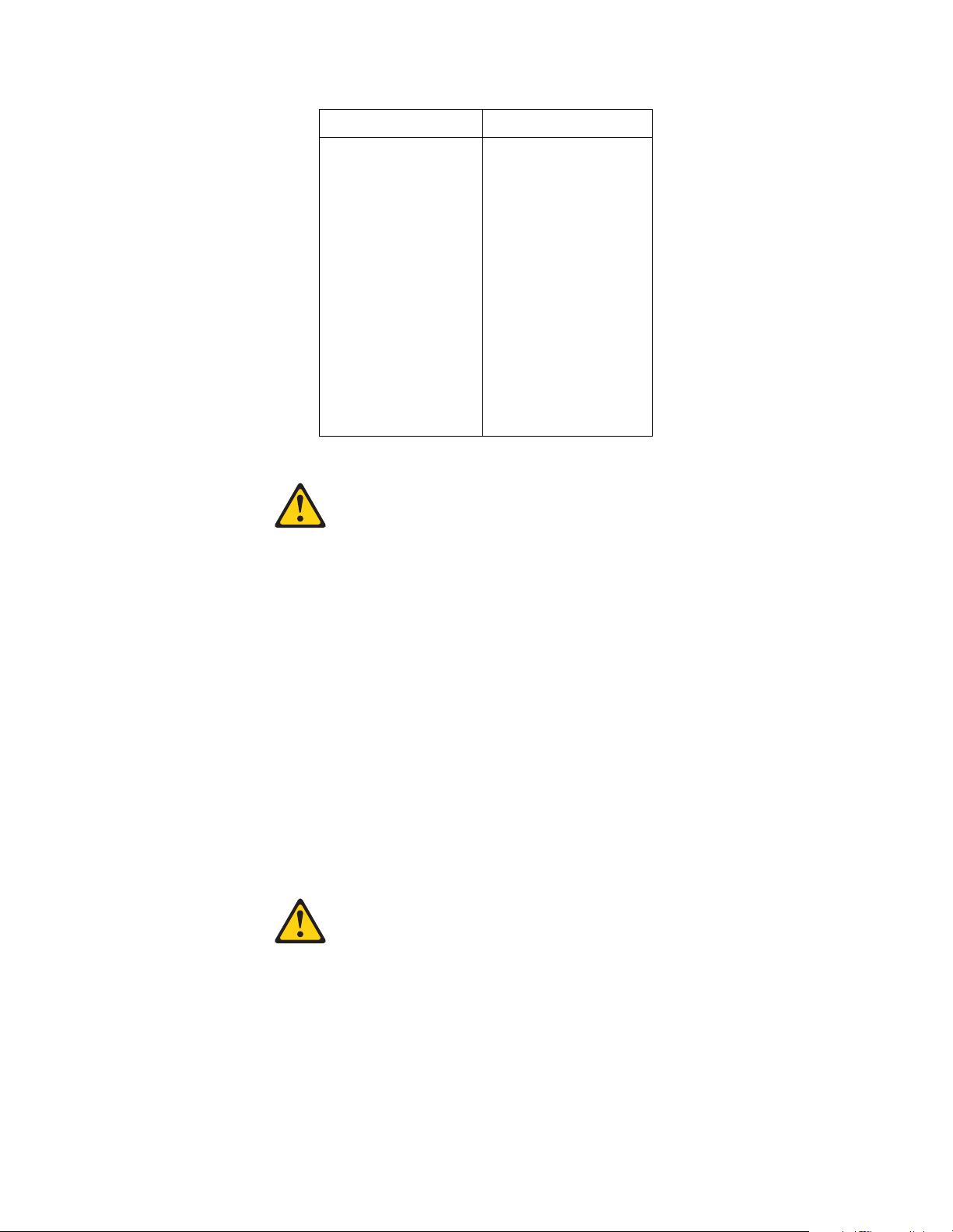
Para la conexin Para la descone xi ín
1. APÁGUELO
todo.
2. En primer lugar,
conecte los cables
a los dispositivos.
3. Conecte los
cables de señal a
los conectores.
4. Conect e ca da
cable de
alimentaciín a la
toma de
1. APÁGUELO todo.
2. En primer lugar ,
retire cada ca bl e
de alime n t aci ín de
la toma de
alimentaciín.
3. Re tire los cable s
de señal de los
conectores.
4. Re tire los cable s
de los
disposit ivos.
alimentaciín.
5. ENCIENDA el
dispositivo.
Declaración 2
PRECAUC IÓ N:
Cuando desee sustituir la batería de litio, utilice únicamente el número de pieza
33F8354 de IBM o cualquier tipo de batería eq uiv al e n te que re comiende el fabricante.
Si el sist ema tien e un mí dulo q ue conti en e una bat erí a de li tio, sust it úyal o únic amente
por el mismo tipo de mídulo, que ha de estar creado por el mismo fabricante. La
batería contiene litio y puede explotar si el usuario no la utiliza ni la maneja de forma
adecuada o si no se desprende de la misma como corresp onde.
No realice las acciones siguientes:
• Arrojarla al agua o sumergirla
• Calentarla a una temperatura que supere l os 100°C (212°F)
• Repararla o desmontarla
Despréndase de la batería siguiendo los requisitos que exija el reglamento o la
legislaciín local.
Declaración 3
PRECAUC IÓ N:
Cuando instale productos láser (como, por ejemplo, CD-ROM, unidades DVD,
disposit ivos de fibra íptica o transmisores), tenga en cuenta las advertencias
siguientes:
• No retire las cubiertas. Si retira las cubiertas del producto láser, puede quedar
expuesto a radiaciín láser perj udicial. Dentr o del dispositivo no existe ninguna
pieza que requiera mantenimiento.
Chapter 2. Related service information 77
Page 86
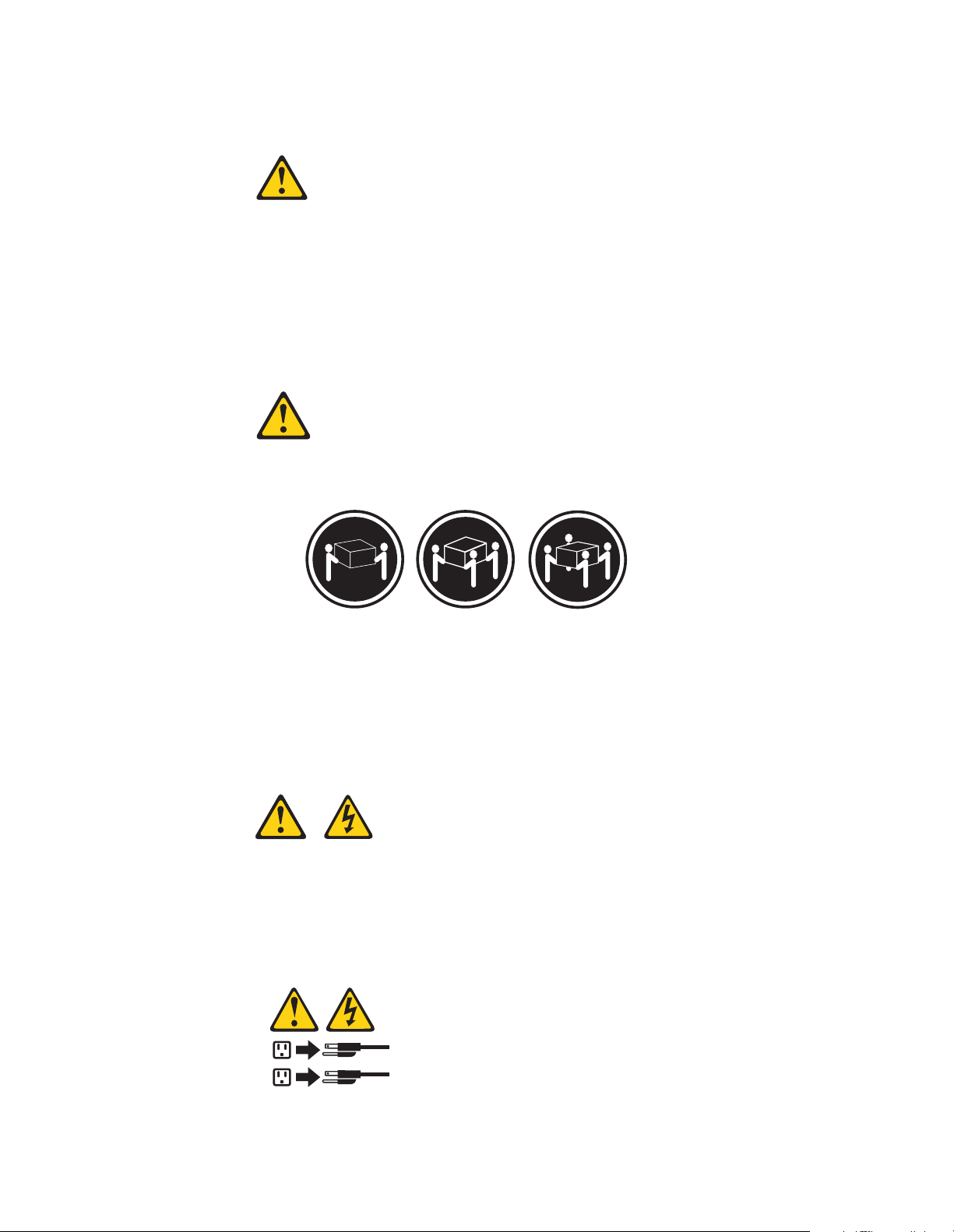
• El uso de controles o ajustes o la realizaciín de procedimientos que no sean los
1
2
que se han especificado aquí pueden dar como resultado una exposiciín
perjudicial a las radiacione s .
PELIGRO
Algunos productos láser contienen un diodo de láser incorporado de Clase 3A o de
Clase 3B. Tenga en cuenta la adver tenci a si g u i e n te.
Cuando se abre, hay radiaci í n láser. No mire fijamente el rayo ni lleve a cabo ningún
examen directamente con instrumentos ípticos; evite la exposiciín dir ect a al rayo.
Declaración 4
≥18 kg (37
libras)
PRECAUC IÓ N:
Tome medidas de seguridad al levantar el producto.
Declaración 5
PRECAUC IÓ N:
El botín de control de alim en ta cií n del disp o s itiv o y el interr up tor de alime ntaciín de
la fuente de alimentaciín no apagan la corrie n te el éctrica suministrada al dispositi vo.
Es posible tamb ién que el disposi t ivo tenga más de un cable de alimentaciín. Para
eliminar la corriente eléctrica del dispositivo, asegúrese de desconectar todos los
cables de alimentaciín de la fuente de alimentaciín.
≥32 kg (70,5
libras)
≥55 kg (121,2
libras)
Decl aración 10
78 IBM Netfinity EXP300 - Type 3531 Hardware Maintenance Manual
Page 87

PRECAUCIÓN:
No coloque ningún objeto que pese más de 82 kg (180 libras) encima de los
dispositivos montados en bastidor.
Chapter 2. Related service information 79
Page 88

Send us your comments!
W e want to know your opinion about this manual (par t number 06P8514) . Your input
will help us to improve our publications.
Please photocopy this sur ve y, complete it, and then fax it to IBM HMM Survey at
919-543-8167 (USA).
Name: _________________________________________
Phone number: __________________________________
1. Do you like this manual?
❑ Yes ❑ No
_________________________________________
_________________________________________
2. What would you like to see ad de d, change d, or dele te d in this manual?
_________________________________________
_________________________________________
3. What is your service experience level?
❑ Less than five years
❑ More than five years
4. Which Servers to you service most?
_________________________________________
_________________________________________
_________________________________________
_________________________________________
Thank you for your response!
Problem determination tips
Due to the variety of hardware and software combin ations that can be encou ntered,
use the following information to assist you in problem determination. If possible,
have this informati on available when requesting assistance from Service Support and
Engineering functions.
80 IBM Netfinity EXP300 - Type 3531 Hardware Maintenance Manual
Page 89

• Machine type and model
• Processor or hard disk upgrades
• Failure symptom
— Do diagnostics fail?
— What, when, where, single, or multiple systems?
— Is the failure repeatable?
— Has this configuration ever worked?
— If it has been working, what changes were made prior to it failing?
— Is this the original reported failure?
• Reference/Diagnostics version
— Type and version level
• Hardware configuration
— Print (print screen) configuration currently in use
—BIOS level
• Operati ng sy stem software
— Type and version level
Note: To eliminate confusion, identical systems are considered identical only if
they:
1. Are the exact machine type and models
2. Have the same BIOS level
3. Have the same ad ap te rs/attachments in the same location s
4. Have the same ad dress jumpers/terminators/cabl ing
5. Have th e same software versions and levels
6. Have the same Refe rence/Diagnostics Diskette (version)
7. Have the same configuration opt ions set in the system
8. Have the same se tup for the operation system control files
Comparing the configuration and software se t- up between "working and
non-working" systems will often lead to problem resolution.
Notices
References in this publication to IBM products, programs, or services do not imply
that IBM intends to make these available in all countries in which IBM operates. Any
reference to an I BM product, program, or se rvice is not intended to state or imply that
only that IBM product, program, or service may be used. Subject to IBM’s valid
intellectual property or other legally protectable rights, any functionally e qui valent
product, program, or service may be used instead of the IBM product, program, or
service. The evaluation and verification of operation in conjun ction with other
products, except those expressly designated by IBM, are the responsibility of the user.
T rademarks
The following items are trademarks of the IBM Corporation in the United States or
other countries or both:
Chapter 2. Related service information 81
Page 90

IBM Netfintiy Director
NetBAY Netfinity
Netfinity Manager ThinkPad
SystemXtra ServeRAID
The follo wing terms are trademar ks of other companies:
Notes Lotus Development Corporation
MMX and Pentium are trademarks or reg istered trademarks of Intel Corpor ation.
UNIX is a trademark or regist ered trademark of The Open Group in the United States
and oth e r countr ie s.
Windows NT is a trademark or registered trademark of Microsof t Corporation.
82 IBM Netfinity EXP300 - Type 3531 Hardware Maintenance Manual
Page 91

Page 92

IBM
Printed in the United States of America
on recycled paper containing 10&
recovered post-consumer fiber.
Part Number: 06P8514
06P8514
Page 93

IBM
 Loading...