

Page 1

S84H-7202-00
IBM PC Servers
PC Server Rack
Storage Enclosure - Type 3519
Hardware Maintenance
Manual Supplement
April 1997
Use this supplement with the
PC Servers Hardware
Maintenance Manual
We Want Your Comments!
(Please see page 37)
IBM
Page 2

Note
Before using this information and the product it
supports, be sure to read the general information
under “Notices” on page 41.
First Edition (May 1997)
The following paragraph does not apply to the United
Kingdom or any country where such provisions are
inconsistent with local law: INTERNATIONAL
BUSINESS MACHINES CORPORATION PROVIDES THIS
PUBLICATION “AS IS” WITHOUT WARRANTY OF ANY
KIND, EITHER EXPRESS OR IMPLIED, INCLUDING, BUT
NOT LIMITED TO, THE IMPLIED WARRANTIES OF
MERCHANTABILITY OR FITNESS FOR A PARTICULAR
PURPOSE. Some states do not allow disclaimer of
express or implied warranties in certain transactions,
therefore, this statement may not apply to you.
This publication could include technical inaccuracies or
typographical errors. Changes are periodically made to
the information herein; these changes will be incorporated
in new editions of the publication. IBM may make
improvements and/or changes in the product(s) and/or the
program(s) described in this publication at any time.
This publication was developed for products and services
offered in the United States of America. IBM may not offer
the products, services, or features discussed in this
document in other countries, and the information is subject
to change without notice. Consult your local IBM
representative for information on the products, services,
and features available in your area.
Requests for technical information about IBM products
should be made to your IBM reseller or IBM marketing
representative.
Copyright International Business Machines
Corporation 1996, 1997. All rights reserved.
Note to U.S. Government users–Documentation related to
Restricted rights–Use, duplication, or disclosure is subject
to restrictions set forth in GSA ADP Schedule Contract
with IBM Corp.
ii PC Server HMM
Page 3

About This Supplement
This supplement contains the following service information
for the PC Server Rack Storage Enclosure - Type 3519.
Diagnostic information
Parts Listing
This supplement should be used with the advanced
diagnostic tests and the information in the IBM PC Servers
Hardware Maintenance Manual Supplement (part number
70H0751, form number S30H-2501) to troubleshoot
problems effectively.
Important
This manual is intended for trained servicers who are
familiar with IBM PC Server products.
Before servicing an IBM product, be sure to review
“Safety Information” on page 30.
iii
Page 4
Related Publications
The following publications are available for IBM products.
For more information, contact IBM or your IBM Authorized
Dealer.
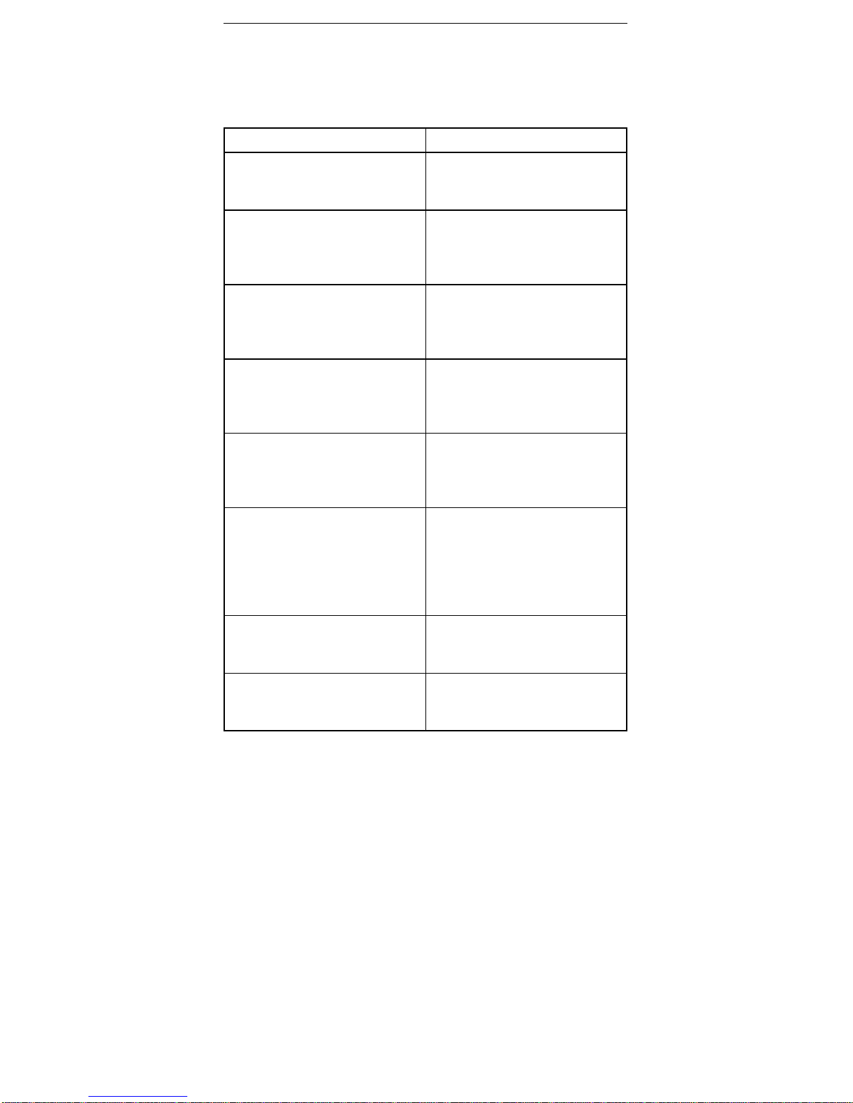
For Information About See Publication
PS/2 Computers IBM Personal System/2
Hardware Maintenance
Manual (S52G-9971)
PS/ValuePoint Computers IBM PS/ValuePoint
Hardware Maintenance
Service and Reference
(S61G-1423)
Laptop, Notebook, and
Portable Computers
IBM Mobile Systems
Hardware Maintenance
Manual Volume 1
(S82G-1501)
ThinkPad computers IBM Mobile Systems
Hardware Maintenance
Manual Volume 2
(S82G-1502)
ThinkPad computers IBM Mobile Systems
Hardware Maintenance
Manual Volume 3
(S82G-1503)
Monitors (Displays) IBM Display Hardware
Maintenance Manual
(SA38-0053)
IBM Monitor Hardware
Maintenance Manual
(S71G-4197)
Disk Array technology
overview and using the IBM
RAID Configuration Program
Configuring Your Disk Array
booklet (S82G-1506)
Installation Planning for
Personal System/2
computers
Personal System/2
Installation Planning and
Beyond (S41G-2927)
iv PC Server HMM
Page 5

Contents
About This Supplement .............. iii
Related Publications . . . . . . . . . . . . . . . iv
PC Server Rack Storage Enclosure - Type 3519 . 1
Features . . . . . . . . . . . . . . . . . . . . . 2
Diagnostics and Test Information ......... 3
Locations . . . . . . . . . . . . . . . . . . . . . 12
Symptom-to-FRU Index . . . . . . . . . . . . . . 24
Parts Listings (PC Server Rack Storage Enclosure -
Type 3519) . . . . . . . . . . . . . . . . . . . 25
Related Service Information ........... 29
Safety Information . . . . . . . . . . . . . . . . 30
Laser Compliance Statement ........... 35
Send Us Your Comments! ............. 37
Problem Determination Tips ............ 38
Phone Numbers, U.S. and Canada ......... 39
Notices . . . . . . . . . . . . . . . . . . . . . . 41
Trademarks . . . . . . . . . . . . . . . . . . . 41
Copyright IBM Corp. 1996, 1997 v
Page 6

PC Server Rack Storage Enclosure Type 3519
Features . . . . . . . . . . . . . . . . . . . . . 2
Diagnostics and Test Information ......... 3
Power-on Self-Test . . . . . . . . . . . . . . 3
Power-on Sequence . . . . . . . . . . . . . . 4
Power Supply (FRU Number 60H8301) ..... 4
Power Supply Shutdowns .......... 5
SCSI IDs . . . . . . . . . . . . . . . . . . 6
SCSI Repeater Cards ............. 7
Connecting Two Servers and One Storage
Enclosure . . . . . . . . . . . . . . . . 8
Connecting One Server and Two Storage
Enclosures . . . . . . . . . . . . . . . . 9
SCSI Termination . . . . . . . . . . . . . . . 10
Specifications . . . . . . . . . . . . . . . . . 11
Locations . . . . . . . . . . . . . . . . . . . . . 12
Access Cover . . . . . . . . . . . . . . . . . 13
Cable Management Arm Bracket ........ 13
Chassis Draw Bracket ............. 13
Controls and Indicators ............. 14
Expansion Bays . . . . . . . . . . . . . . . . 15
Drive Bays 1 to 3 .............. 16
Hot-Swap Drives Bays 4 through 9 ..... 17
External Connectors . . . . . . . . . . . . . . 18
Front Door . . . . . . . . . . . . . . . . . . 18
Hot-Swap Drive Tray III ............ 19
Keylock Assembly Exploded View ....... 20
Rack Slides . . . . . . . . . . . . . . . . . . 20
SCSI Repeater Card .............. 21
Slide Management Bracket ........... 21
Voltage Setting . . . . . . . . . . . . . . . . 23
Symptom-to-FRU Index . . . . . . . . . . . . . . 24
Parts Listings (PC Server Rack Storage Enclosure -
Type 3519) . . . . . . . . . . . . . . . . . . . 25
System (Model R01) .............. 26
Power Cords . . . . . . . . . . . . . . . . . 27
Copyright IBM Corp. 1996, 1997 1
Page 7

Features
The features in the storage enclosure vary according to the
model. The following is a summary of the features that are
available with the PC Server Rack Storage Enclosure Type 3519.
Expansion Bays
Nine:
– Six hot-swap
– Up to three slim-high or two half-high non-hot-swap
devices
Options Supported
Up to six slim-high or three half-high hot-swap hard disk drives
Tape autoloader
4/10 GB 3.5-inch DAT tape drive
CD-ROM drive
Security Features
Door lock
Fan failure detection
Integrated Functions
LED usability support
SCSI Repeater Card:
– One card standard
– Supports maximum of two
Power Supply
200-watt with manual voltage selection (100–240 Vac)
Built-in overload and surge protection
Hard Disk Drives
Supports up to six hot-swap and three non-hot-swap
2 PC Server HMM
Page 8
Diagnostics and Test Information
Important
The service procedures are designed to help you
isolate problems. They are written with the
assumption that you have model-specific training on
all computers, or that you are familiar with the
computers, functions, terminology, and service-related
information provided in this supplement and the PC
Servers Hardware Maintenance Manual (part number
70H0751, form number S30H-2501-01).
The following is a list of problems and references for
diagnosing the PC Server Rack Storage Enclosure - Type
3519.
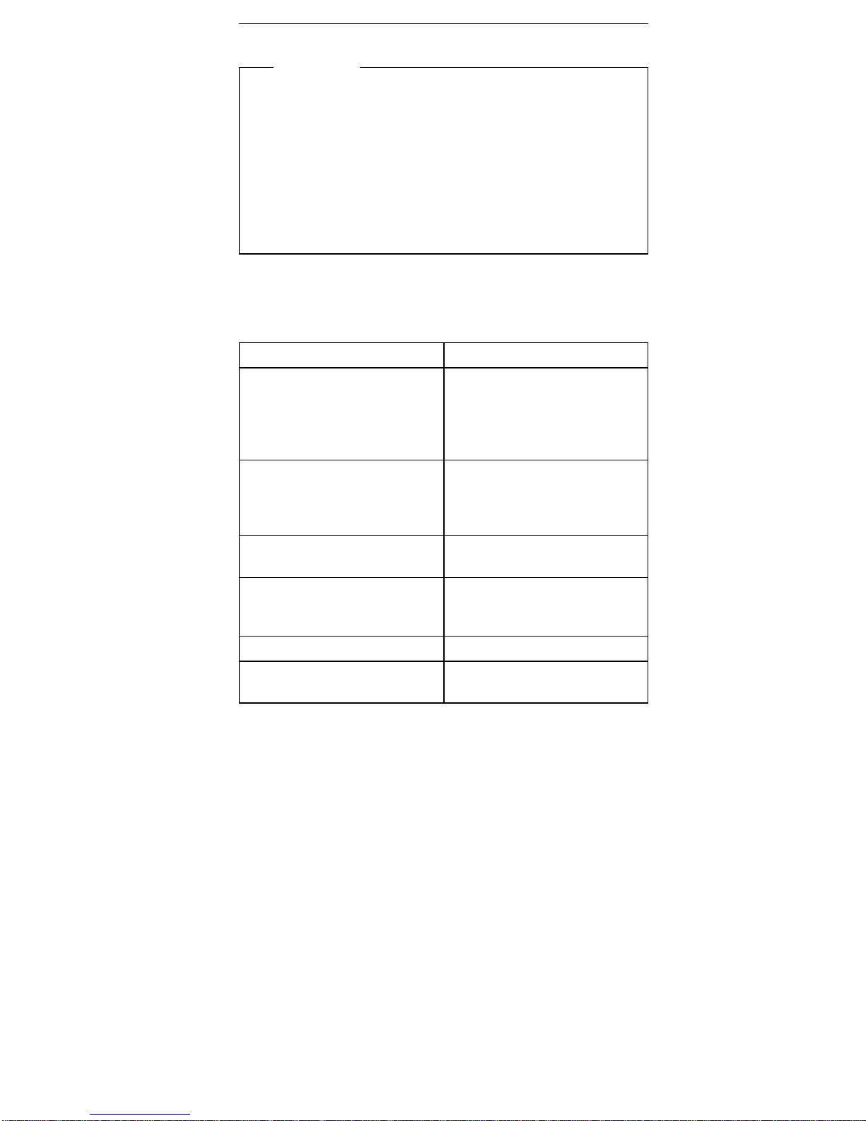
Problem Reference
Error Codes/Error Messages Refer to the
Symptom-to-FRU Index for
the server that the Storage
Enclosure you are servicing
is connected to.
Fan Light indications See “Controls and
Indicators” on page 14 and
“Symptom-to-FRU Index” on
page 24.
Hot Swap Tray LED
indications
See “Hot-Swap Drive Tray
III” on page 19.
Power Supply Voltages See “Power Supply (FRU
Number 60H8301)” on
page 4.
Setting SCSI IDs See “SCSI IDs” on page 6.
Terminating a SCSI chain See “SCSI Termination” on
page 10.
Power-on Self-Test
When you power-on the server, it performs a series of
tests to check the operation of the system, including the
drives and other components of the storage enclosure.
This series of tests is called the
power-on self-test
, or
POST
. If the tests indicate a problem, a message appears
on the server's information panel or display.
Rack Storage Enclosure - Type 3519 3
Page 9
Power-on Sequence
Note
For normal operation, power on the server; then,
power on the expansion enclosure.
The expansion enclosure can be powered on without
connecting it to a server. However, the expansion
enclosure must be connected to a server before the drives
installed in the enclosure can be used.
Power Supply (FRU Number 60H8301)
Note
Verify that the voltage-select switch is set for the
correct voltage. If the voltage switch is set to the
wrong position, permanent damage might occur to the
rack when you power it on.
If the power-on indicator is not on, and the power-supply
fan is not running, check the power cord for proper
installation and continuity.
If the power cord is OK, either the power supply is
defective or a defective device is causing the power supply
to shut off. Check the power supply voltages.
The power supply is rated at 200 watts. Too many
devices (adapters or hard disk drives) can cause power
consumption to exceed 200 watts and cause the power
supply to shut down. See “Power Supply Shutdowns” on
page 5. Remove adapters or devices to determine if this
is the cause.
If the voltages are incorrect, replace the power supply.
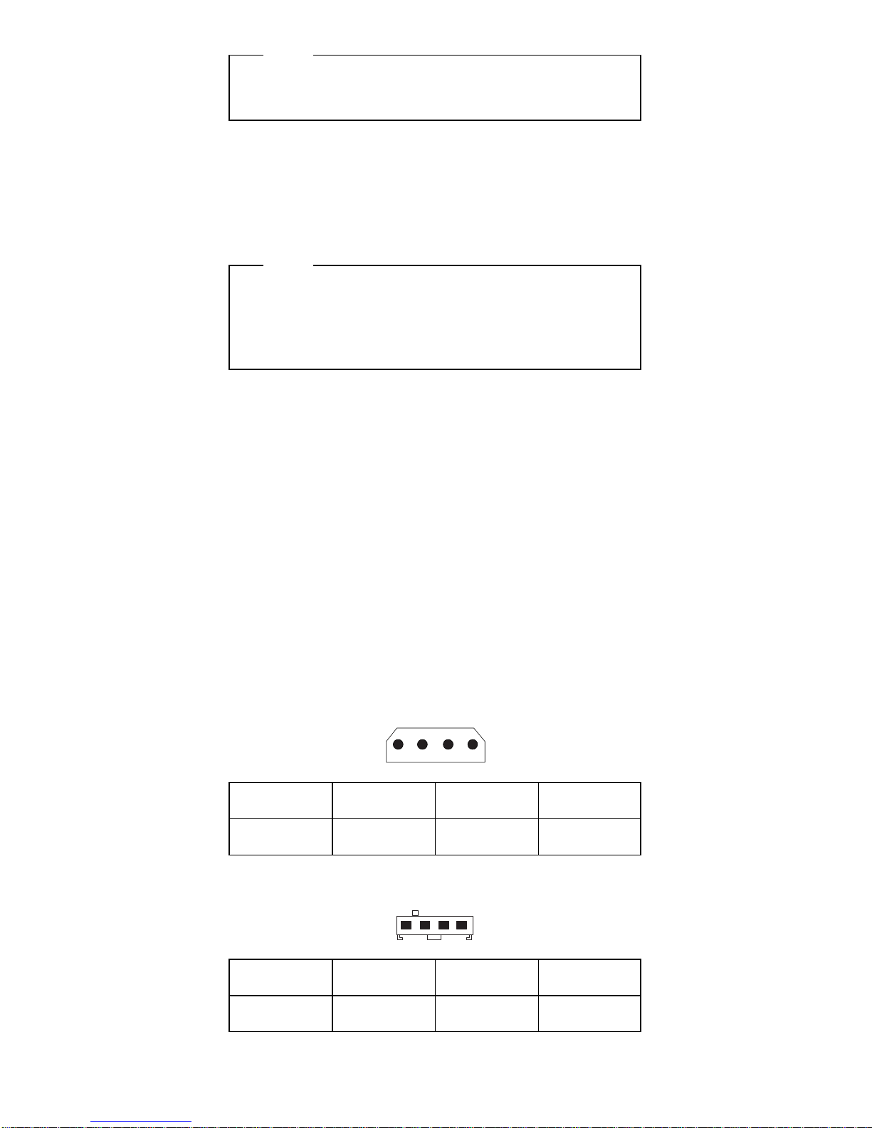
DASD Connectors P1, P2, P3, P4, P5, P6, P7, P8
14
Aux SCSI Board Power Connectors P9, P10
41
−Lead
Pin
+Lead
Pin
V dc
Minimum
V dc
Maximum
2
3
1
4
+11.52V
+4.8V
+12.6V
+5.25V
−Lead
Pin
+Lead
Pin
V dc
Minimum
V dc
Maximum
2
3
1
4
+11.52V
+4.8V
+12.6V
+5.25V
4 PC Server HMM
Page 10
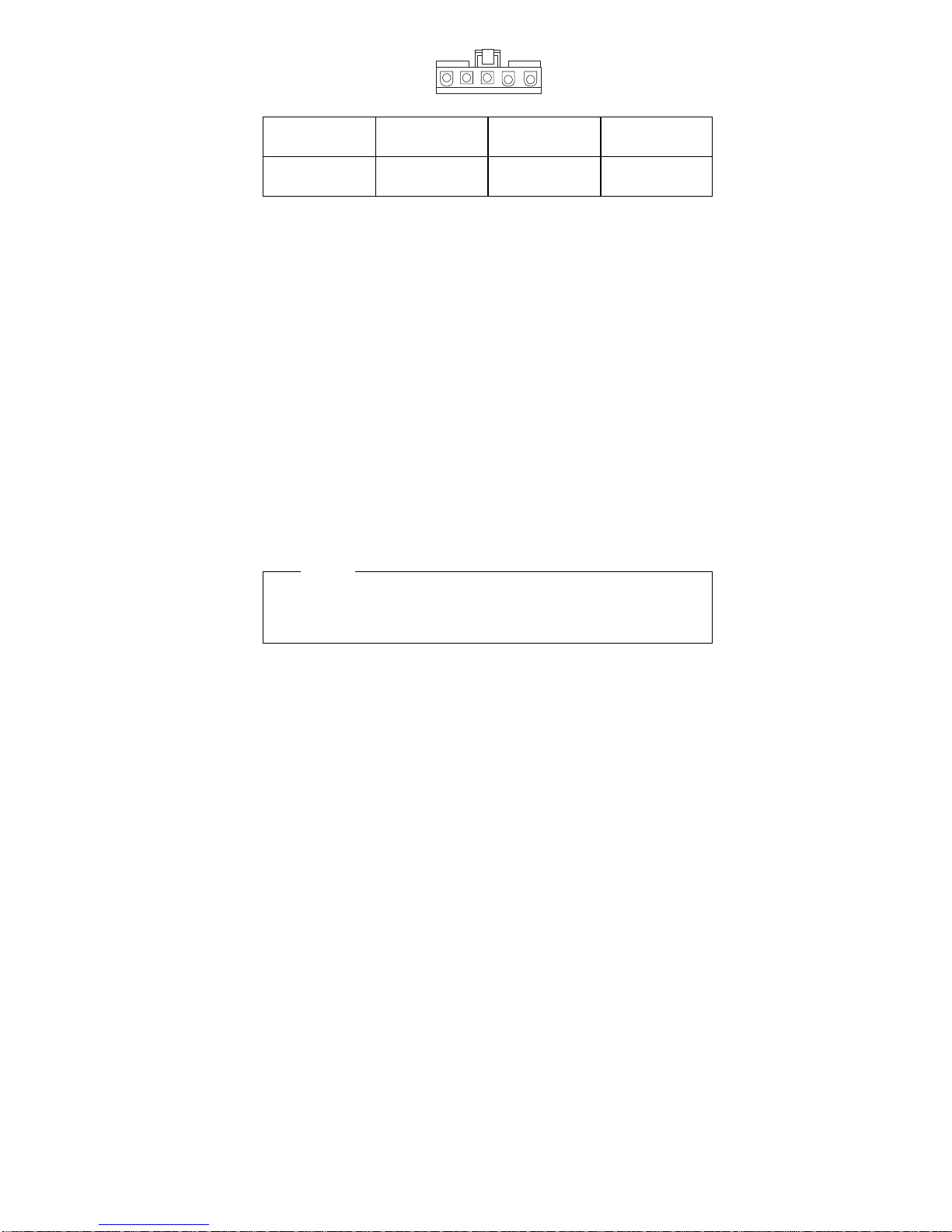
Switch Board Connector P11
5
1
Power Supply Shutdowns:
If the power supply shuts down, or
appears
to fail at
power-on, you might have one of the following problems:
Too many devices are set to start instantly. See
“Setting the Motor-Start Jumper” on page 414 in the
PS/2 Hardware Maintenance Manual.
There are too many large-capacity devices installed
(such as hard disk drives). The nominal operating
current of the devices installed collectively exceeds
the available current of the power supply. See the
“Personal System/2 Installation Planning” guide (form
number S41G-2927) for more information.
Also ensure that the fans operate when the machine is
powered on.
Note
Verify that the voltage-select switch (if applicable) is
set for the correct voltage.
−Lead
Pin
+Lead
Pin
V dc
Minimum
V dc
Maximum
5
5
4
3
+11.52V
+4.8V
+12.6V
+5.25V
Rack Storage Enclosure - Type 3519 5
Page 11
SCSI IDs: Each SCSI device installed in the storage
enclosure must have a unique SCSI identifier (ID). This
unique ID enables the SCSI controller to recognize the
device. This SCSI ID also prevents two devices from
attempting to send or receive data on the SCSI bus at the
same time. IBM PC Server SCSI controllers use ID 7.
Therefore, you must not assign ID 7 to any device that you
install in the storage enclosure. SCSI devices support the
following IDs:
Narrow devices support SCSI IDs 0 to 6.
Wide devices support 0 to 6 or 8 to 15.
When you install a hot-swap drive, the backplane behind
bays 4 through 9 automatically assigns the drive its SCSI
ID. However, when you install a drive in bays 1 through 3,
you must set a unique SCSI ID for the drive that does not
conflict with any of the IDs that the backplane assigns to
drives in bays 4 through 9.
Depending on the setting of the SCSI ID address jumper
(J12) on the rear of the backplane, the backplane sets the
SCSI IDs for bays 4 through 9. SCSI IDs 8 to 13 are the
default IDs for the hot-swap drives. SCSI IDs 0 to 5 are
also available for the hot-swap drives.
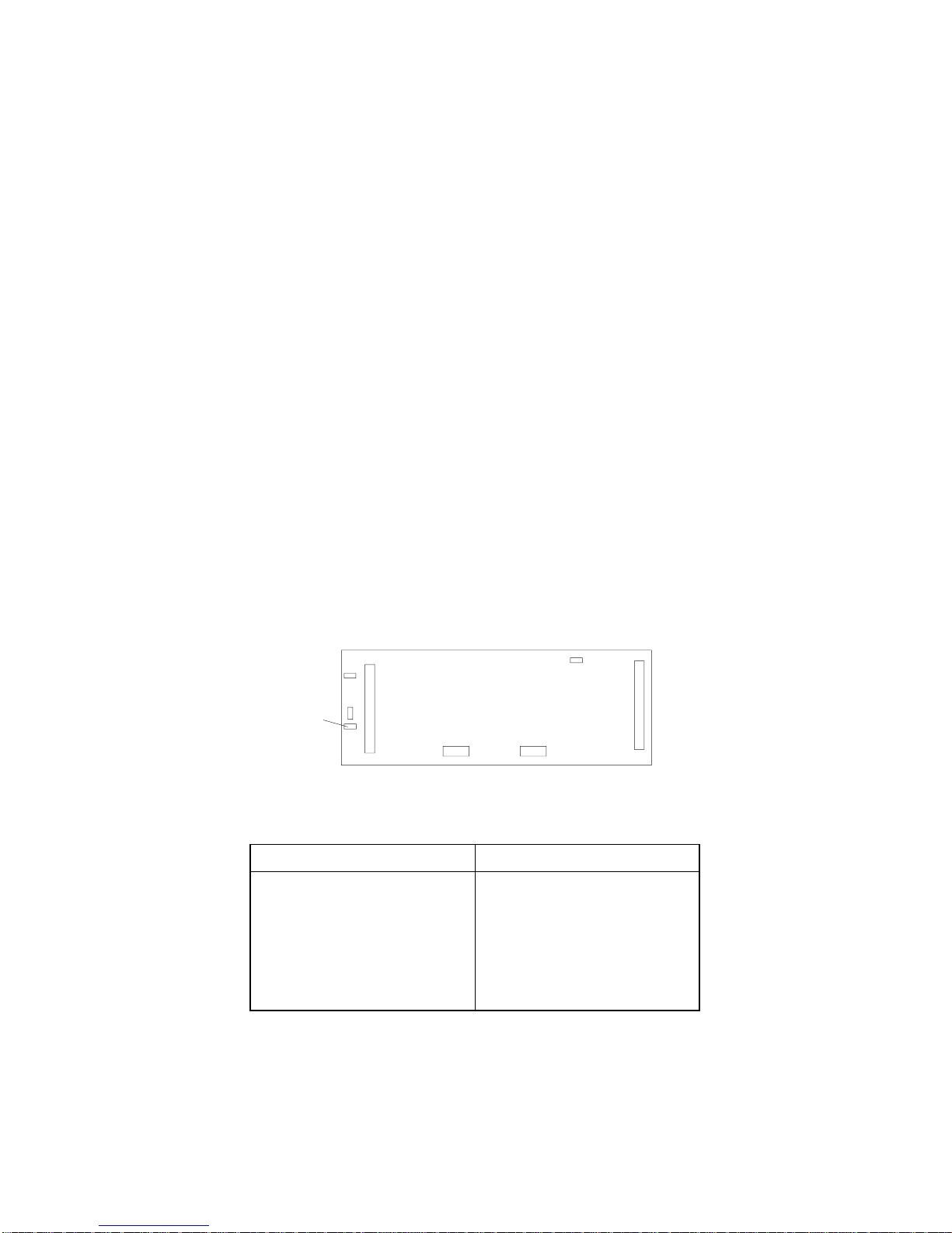
The SCSI ID address jumper, a pin block with four pairs of
pins (J12), is located on the rear of the backplane. The
default, cover installed on the HI ID N pins, sets the
addresses to HI.
J12
The backplane sets the SCSI IDs for bays 4 through 9 as
follows:
LO Settings HI Settings (default)
Bay SCSI ID
4 0
5 1
6 2
7 3
8 4
9 5
Bay SCSI ID
4 8
5 9
6 10
7 11
8 12
9 13
6 PC Server HMM
Page 12
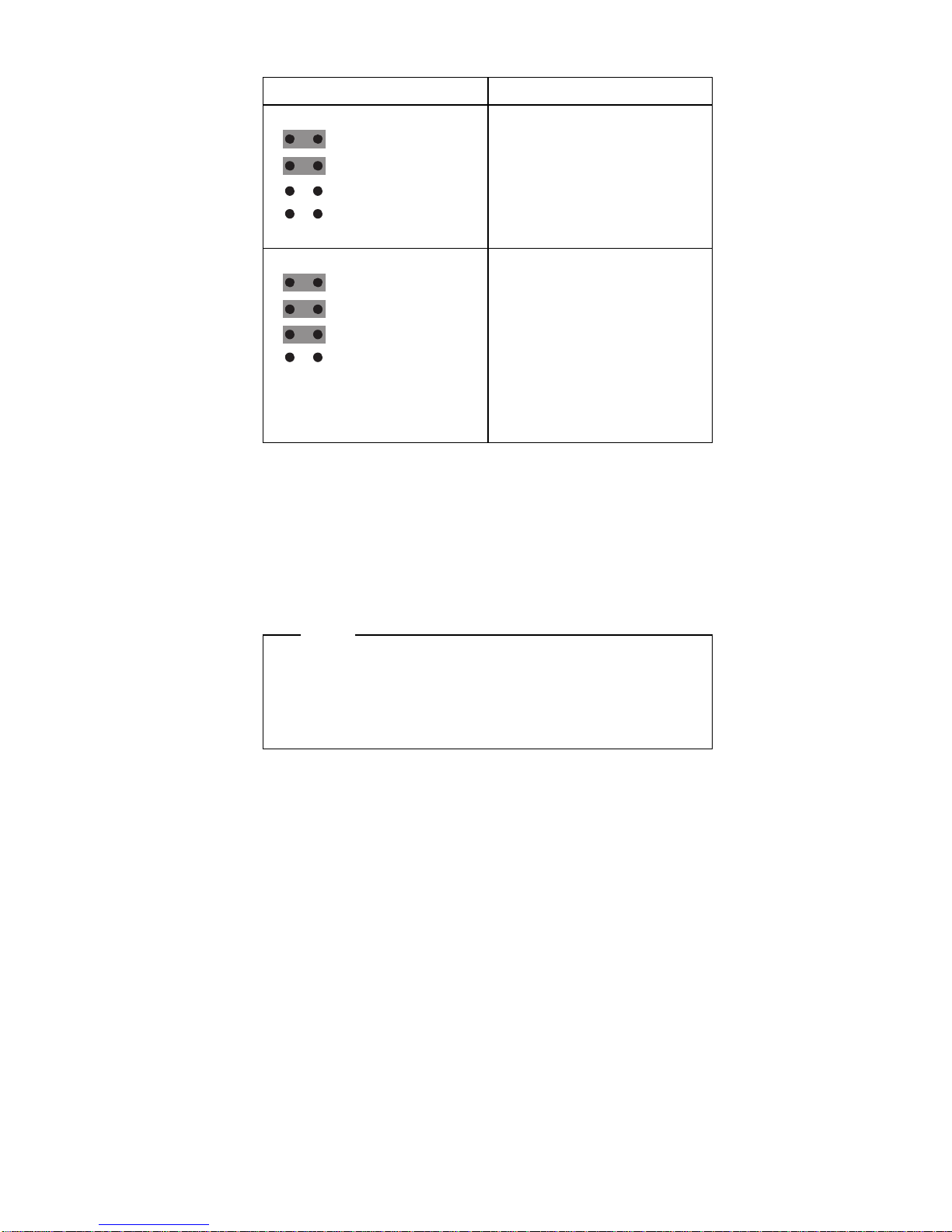
The following table summarizes the jumper settings for the
SCSI ID address jumper (J12).
Refer to the documentation that came with the drive for
information about setting its SCSI ID.
If the storage enclosure is attached to a RAID adapter,
refer to the information that came with the adapter for
SCSI ID requirements.
Jumper Position Description
LO
J12
SYS RST
ID REV
HI ID N
HP PULSE N
No cover installed on the HI
ID N pins, sets SCSI IDs to
LO.
HI
J12
SYS RST
ID REV
HI ID N
HP PULSE N
Sets SCSI IDs to HI. Use
this setting, cover installed
on the HI ID N pins, when
you install narrow
non-hot-swap devices and
the configuration requires
you to define some
non-hot-swap devices with
high IDs. This is the default
setting.
SCSI Repeater Cards
Note
If you connect the storage enclosure to a
non-disk-array server, the SCSI bus must be
dedicated to the storage enclosure. That is, you
cannot connect other devices to the SCSI bus.
The storage enclosure comes equipped to connect to one
server. To connect:
Two servers and one storage enclosure, see
“Connecting Two Servers and One Storage
Enclosure” on page 8.
One server and two storage enclosures, see
“Connecting One Server and Two Storage
Enclosures” on page 9.
Rack Storage Enclosure - Type 3519
7
Page 13
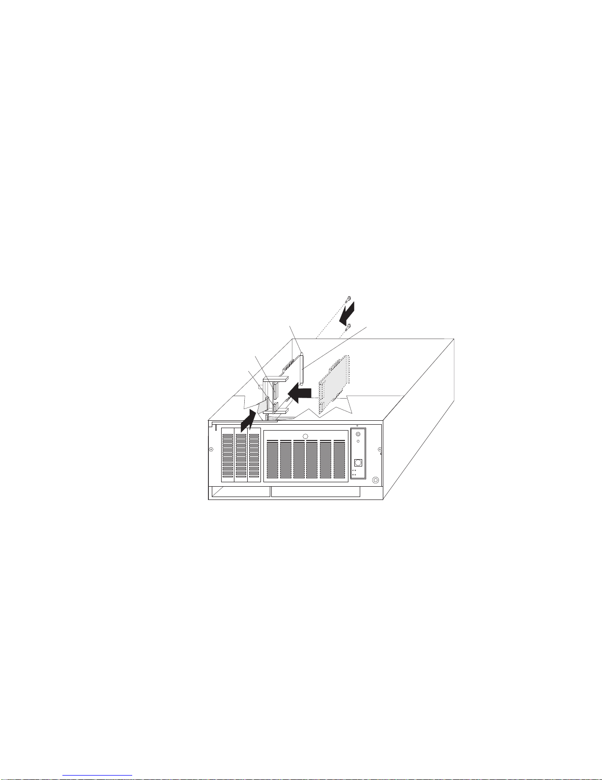
Connecting Two Servers and One Storage
Enclosure: To install a second SCSI Repeater Card
to connect two servers and the storage enclosure, do the
following.
1. Set the SCSI ID address jumper on the backplane of
the storage enclosure to HI. See “SCSI IDs” on
page 6 for information on the SCSI ID address
jumper.
2. Assign a unique SCSI ID to the SCSI controller of
each server. For example, if the SCSI controller in
both servers is set to 7, set the SCSI ID of one SCSI
controller to 6.
3. Install the SCSI Repeater Card in the expansion
enclosure.
4. Connect the power cable to the SCSI Repeater Card.
5. Connect one end of the SCSI option cable to the
internal SCSI connector on the SCSI Repeater Card;
then, connect the other end of the cable to the
backplane on the storage enclosure.
External SCSI
Connector
Power Connector
Internal SCSI
Connector
SCSI Knockout
Panel
8 PC Server HMM
Page 14
Connecting One Server and Two Storage
Enclosures
Note
You must have a Y-cable available for connecting the
server and storage enclosures. The Y-cable can be
ordered from an IBM marketing representative or an
IBM reseller.
To connect the storage enclosure to one server and
another storage enclosure, do the following.
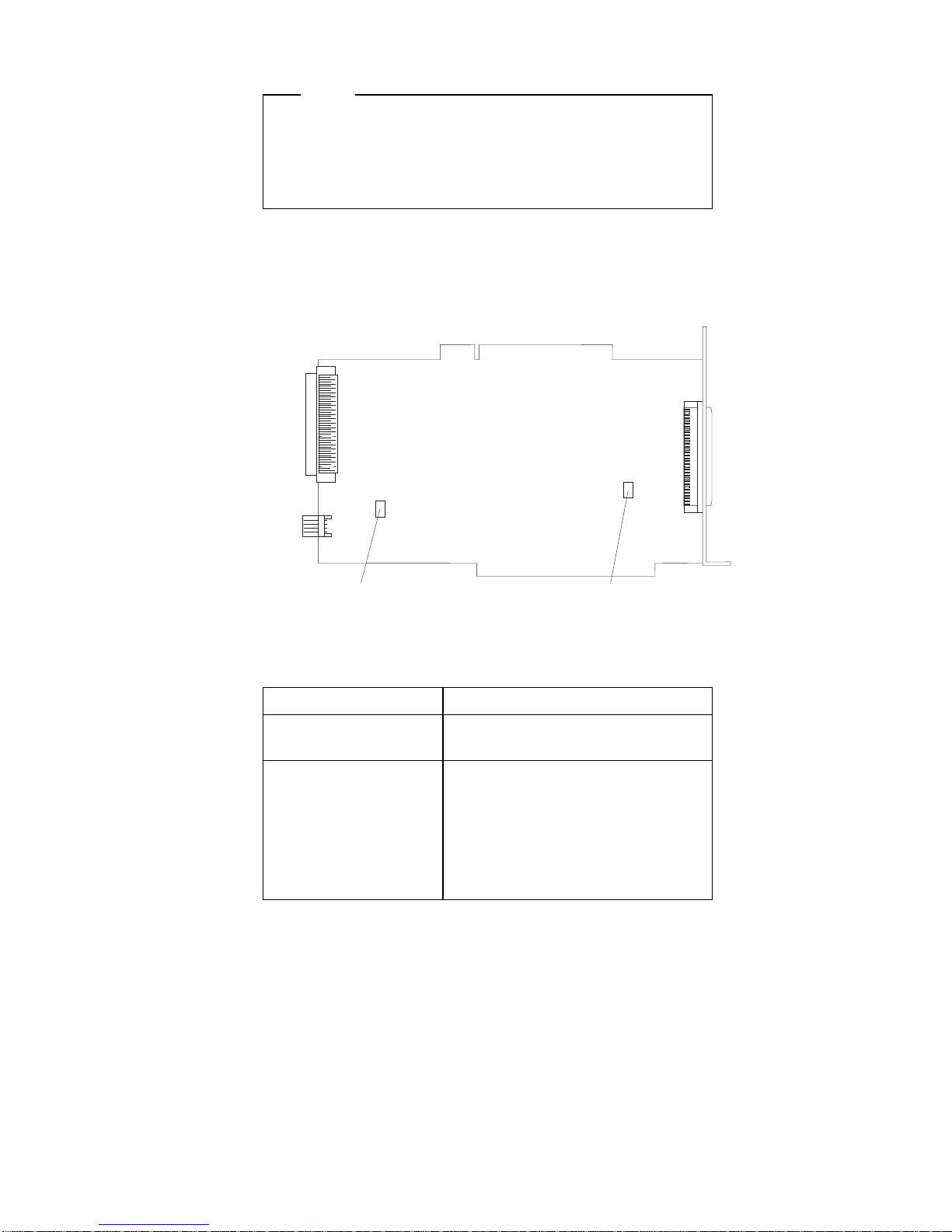
1. Set jumpers (J3 and J6) on the SCSI Repeater Card.
J3
J6
The default settings for both jumpers is ON (covers
on each jumper). The following table summarizes the
jumper settings for the SCSI Repeater Card jumpers.
Jumper Description
J3 Leave the jumper in the ON
position.
J6 Use the OFF position (cover
removed) to connect the
storage enclosure to the
double connector of a
Y-cable.
Use the ON position (cover in
place) in all other cases.
Rack Storage Enclosure - Type 3519 9
Page 15

2. Set the SCSI ID address jumpers on the backplanes
of the storage enclosures. See “SCSI IDs” on page 6
for information on the SCSI ID address jumpers. The
following illustrates cabling and jumper setting
requirements.
J3 ON
J6 ON
HI
J3 ON
J6 OFF
LO
Backplane
Jumpers
SCSI Address
Jumpers
Expansion
Enclosure 2
Expansion
Enclosure 2
Expansion
Enclosure 1
Expansion
Enclosure 1
Server
Double
Cable
Connector
Y-Cable
The storage enclosures can contain a maximum of
twelve slim-high, or six half-high hot-swap drives.
SCSI Termination
Termination ensures that the quality of the signal is
maintained throughout the SCSI chain. If you chain SCSI
devices in bays 1 through 3, the backplane automatically
sets termination for all devices. The backplane also
automatically sets termination for hot-swap drives.
Before you install a SCSI device, set the termination to
DISABLED. On some devices, you will need to remove
jumpers. Refer to the information that came with the
device for instructions.
10 PC Server HMM
Page 16

Specifications
Size
Depth: 465 mm (18.3 in.)
Height: 216 mm (8.5 in.)
Width: 482 mm (19.0 in.)
Weight
Typical storage enclosure as shipped: 17 kg (37.5 lb)
Environment
Air temperature:
– Storage Enclosure on:
10° to 35° C
(50° to 95° F)
Altitude: 0 to 914 m (3000 ft.)
– Storage Enclosure on:
10° to 32° C
(50° to 90° F)
Altitude: 914 m (3000 ft.) to 2133 m (7000 ft.)
– Storage Enclosure off:
10° to 43° C
(50° to 110° F)
Maximum Altitude: 2133 m (7000 ft.)
Humidity:
– Storage Enclosure on:
8% to 80%
– Storage Enclosure off:
8% to 80%
Maximum altitude: 2133 m (7000 ft)
Electrical Input
Sine-wave input (50 to 60 Hz) is required
Input voltage:
– Low range:
- Minimum: 90 V ac
- Maximum: 137 V ac
– High range:
- Minimum: 180 V ac
- Maximum: 265 V ac
– Input kilovolt-amperes (kVA) approximately:
- Minimum configuration as shipped: 0.08 kVA
- Maximum configuration: 0.52 kVA
Total Power Available for Drives
Nominal Operating Current allowed:
– +5 V dc line: 5.3 A
– +12 V dc line: 5.0 A
Heat Output
Approximate heat output in British Thermal Units (Btu) per
hour:
– Minimum configuration:
350 Btu (102 watts)
– Maximum configuration:
860 Btu (251 watts)
Rack Storage Enclosure - Type 3519 11
Page 17

Locations
“Access Cover” on page 13.
“Cable Management Arm Bracket” on page 13.
“Chassis Draw Bracket” on page 13.
“Controls and Indicators” on page 14.
“Expansion Bays” on page 15.
“External Connectors” on page 18.
“Front Door” on page 18.
“Hot-Swap Drive Tray III” on page 19.
“Keylock Assembly Exploded View” on page 20.
“Rack Slides” on page 20.
“SCSI Repeater Card” on page 21.
“Slide Management Bracket” on page 21.
“Voltage Setting” on page 23.
12 PC Server HMM
Page 18

Access Cover
Captive Screws
Cable Management Arm Bracket
Chassis Draw Bracket
Rack Storage Enclosure - Type 3519 13
Page 19

Controls and Indicators
Reset Switch
Power Switch
Power-On Light
Fan Failure Light
Attention
The storage enclosure produces heat. Fans in the
storage enclosure pull in fresh air and force out hot
air. Operating the storage enclosure with an idle fan
can cause overheating, which might result in a
malfunction or damage.
Reset
Switch:
Use to cancel the fan failure warning buzzer.
Power
Switch:
Use to power the storage enclosure on and off.
To power-on the storage enclosure, press the
Power switch momentarily, and the Power On
indicator will illuminate in approximately one
second.
Power-On
Light:
This green LED lights when the storage
enclosure is powered on by pressing the Power
switch.
Fan
Failure
Light:
This amber LED lights if one or more of the
internal fans fail.
Note
If one or more fans remain idle, a warning
buzzer sounds. Press the Reset switch to
silence the warning buzzer.
14 PC Server HMM
Page 20

Expansion Bays
1 23456789
Table 1. Maximum Allowable Drive Sizes
Bay Drive Width Drive Type Drive Height
1 – 3 3.5-inch
5.25-inch
Removable
media drive1,
hard disk
drive
2
41.3 mm (1.6
in.)
4 – 9 3.5-inch Hot-Swap
3
25.4 mm (1.0
in.)
41.3 mm (1.6
in.)
Notes:
1. Removable media includes CD-ROMs, optical discs, and
tape.
2. You can install a maximum of two 41.3 mm drives.
3. A 41.3 mm drive installed in bays 4 through 9 occupies
two bays.
Rack Storage Enclosure - Type 3519 15
Page 21

Drive Bays 1 to 3
16 PC Server HMM
Page 22

Hot-Swap Drives Bays 4 through 9
Unlocked
Position
Locked
Position
Rack Storage Enclosure - Type 3519 17
Page 23

External Connectors
Power Connector
External SCSI Connector
( 68 Pin )
Note
See “SCSI Repeater Cards” on page 7 for information on
external connector requirements.
Power
Connector:
The storage enclosure power cable connects
here.
External
SCSI
Connector:
A SCSI cable attaches here, and connects
to the external SCSI connector on the
server. For disk-array servers, the cable
connects to the external SCSI connector on
a RAID adapter.
Front Door
Flange
18 PC Server HMM
Page 24

Hot-Swap Drive Tray III
Locked
Position
Green
Light
Amber
Light
Notes
1. Each hot-swap drive that you plan to install must
have a hot-swap drive tray III attached.
2. Trays are available for two drive types: narrow
and wide. The narrow tray supports 8-bit drives;
the wide tray supports 16-bit drives.
Green Amber Description
On Off Drive tray is powered on; the hard
disk drive is inactive; and the drive
should
not
be removed.
Blinking Off The hard disk drive is inactive.
The hot-swap drive can be
removed safely.
Note
This indication will only
appear if the expansion
enclosure is attached to a
RAID adapter.
On On or
Blinking
The hard disk drive is in use, and
should
not
be removed.
Off Off The drive is defective, or no power
is being supplied to the drive. The
hot-swap drive can be removed
safely.
Attention
Press the small switch on the
drive before you remove the
drive.
Rack Storage Enclosure - Type 3519 19
Page 25

Keylock Assembly Exploded View
Rack Slides
20 PC Server HMM
Page 26

SCSI Repeater Card
Power Connector
Internal SCSI
Connector
SCSI Knockout
Panel
External SCSI
Connector
Slide Management Bracket
Rack Storage Enclosure - Type 3519 21
Page 27

22 PC Server HMM
Page 28

Voltage Setting
Attention: If you set the voltage switch to the wrong
position, you might permanently damage your storage
enclosure when you turn it on.
If the voltage range in your country is between 100
and 127 volts, check to see that 115 is visible. (Use
the 115-volt setting in the U.S. and Canada.)
If the voltage range in your country is between 200
and 240 volts, check to see that 230 is visible.
To adjust the voltage setting, slide the switch to the correct
position.
115V
Rack Storage Enclosure - Type 3519 23
Page 29

Symptom-to-FRU Index
This index supports the PC Server Rack Storage
Enclosure - Type 3519.
The Symptom-to-FRU Index lists symptoms and the
possible causes. The most likely cause is listed first. Use
this Symptom-to-FRU Index to help you decide which
FRUs to have available when servicing the rack enclosure.
Symptom FRU/Action
Expansion Enclosure will
not power-on.
1. Check voltage
switch, power cord,
power source and
cables.
2. Check the Power
Supply , see “Power
Supply (FRU Number
60H8301)” on page 4.
Fan Failure buzzer sounds,
Fan Failure LED lights, or
one or more of the internal
fans is not operating.
Attention
Do not operate the
expansion enclosure
unless all fans are
working properly.
1. Fan
2. Power Supply
SCSI Repeater Card that
was just installed does not
work.
1. Check termination
(See “SCSI
Termination” on
page 10.)
2. Repeater Card
3. SCSI Adapter that the
repeater card is
connected to.
SCSI Repeater Card that
used to work does not work
now.
1. Check termination
(See “SCSI
Termination” on
page 10.)
2. Repeater Card
3. SCSI Adapter that the
repeater card is
connected to.
SCSI device that used to
work does not work now.
1. Check SCSI ID
settings (See “SCSI
IDs” on page 6.)
2. Check termination
(See “SCSI
Termination” on
page 10.)
3. SCSI Device
4. Repeater Card
5. SCSI Adapter that the
repeater card is
connected to.
24 PC Server HMM
Page 30

Parts Listings (PC Server Rack Storage
Enclosure - Type 3519)
1
2
3
4
5
6
7
8
9
10
11
12
13
14
15
16
17
18
19
20
21
22
Rack Storage Enclosure - Type 3519 25
Page 31

System (Model R01)
Index System (PC Server Rack Storage
Enclosure - Type 3519)
Model R01
FRU No.
1 Access Cover with Rear Bezel 72H2643
2 Fan Assembly 120 mm with Connector 60H9308
3 200W UV PFC Power Supply Assembly 60H8301
4 Base Frame Assembly 60H9283
5 Access Cover with Rear Bezel 72H2643
6 Hot-Plug Backplane 06H8576
7 Front Bezel Rack 60H8300
8 Cable Management Arm Bracket 72H2674
9 Chassis Draw Bracket 72H2676
10 Slide Management Bracket 72H2655
11 Rack Slides 72H2653
12 Slide Management Bracket 72H2655
13 Cable Management Arm 72H2657
14 Keylock with Keys 33F8433
15 Front Door Assembly Rack 60H8308
16 5.25-Inch Blank Bezel 76H3451
17 LED/On/Off Switch Cable Assembly 60H8302
18 Hot-Swap Door Assembly 60H9284
19 DASD Tray 06H2652
20 4.3 m 68/68 Cable 76H0501
21 SCSI Repeater Card 93H6409
22 Internal SCSI Cable 5X 60H8304
Miscellaneous Parts Kit 55H8179
PC Server Label 60H8306
Power Cords (See, “Power Cords” on
page 27.)
Push Catch and Bracket 60H9285
26 PC Server HMM
Page 32

Power Cords
PC Server Rack Storage Enclosure - Type 3519
FRU
No.
Arabic 14F0033
Belgium 1339520
Bulgaria 1339520
Czech Republic 1339520
Denmark 13F9997
Finland 1339520
France 1339520
Germany 1339520
Hungary 1339520
Israel 14F0087
Italy 14F0069
Latvia 1339520
Netherlands 1339520
Norway 1339520
Poland 1339520
Portugal 1339520
Serbia 1339520
Slovakia 1339520
South Africa 14F0015
Spain 1339520
Switzerland 1339520
Switzerland (French/German) 14F0051
U.S. English 62X1045
U.K./Ireland 14F0033
Yugoslavia 1339520
Rack Storage Enclosure - Type 3519 27
Page 33

Related Service Information
Safety Information . . . . . . . . . . . . . . . . 30
General Safety . . . . . . . . . . . . . . . . 30
Electrical Safety . . . . . . . . . . . . . . . . 31
Safety Inspection Guide ............ 32
Handling Electrostatic Discharge-Sensitive Devices 34
Grounding Requirements . . . . . . . . . . . . 34
Laser Compliance Statement ........... 35
Send Us Your Comments! ............. 37
Problem Determination Tips ............ 38
Phone Numbers, U.S. and Canada ......... 39
Notices . . . . . . . . . . . . . . . . . . . . . . 41
Trademarks . . . . . . . . . . . . . . . . . . . 41
Copyright IBM Corp. 1996, 1997 29
Page 34

Safety Information
The following section contains the safety information that
you need to be familiar with before servicing an IBM
computer.
General Safety
Follow these rules to ensure general safety:
Observe good housekeeping in the area of the
machines during and after maintenance.
When lifting any heavy object:
1. Ensure you can stand safely without slipping.
2. Distribute the weight of the object equally
between your feet.
3. Use a slow lifting force. Never move suddenly
or twist when you attempt to lift.
4. Lift by standing or by pushing up with your leg
muscles; this action removes the strain from the
muscles in your back.
Do not attempt to lift any
objects that weigh more than 16 kg (35 lb) or
objects that you think are too heavy for you.
Do not perform any action that causes hazards to the
customer, or that makes the equipment unsafe.
Before you start the machine, ensure that other
service representatives and the customer's personnel
are not in a hazardous position.
Place removed covers and other parts in a safe
place, away from all personnel, while you are
servicing the machine.
Keep your tool case away from walk areas so that
other people will not trip over it.
Do not wear loose clothing that can be trapped in the
moving parts of a machine. Ensure that your sleeves
are fastened or rolled up above your elbows. If your
hair is long, fasten it.
Insert the ends of your necktie or scarf inside clothing
or fasten it with a nonconductive clip, approximately 8
centimeters (3 inches) from the end.
Do not wear jewelry, chains, metal-frame eyeglasses,
or metal fasteners for your clothing.
Remember: Metal objects are good electrical
conductors.
Wear safety glasses when you are: hammering,
drilling soldering, cutting wire, attaching springs, using
solvents, or working in any other conditions that might
be hazardous to your eyes.
After service, reinstall all safety shields, guards,
labels, and ground wires. Replace any safety device
that is worn or defective.
Reinstall all covers correctly before returning the
machine to the customer.
30 PC Server HMM
Page 35

Electrical Safety
Observe the following rules when working on electrical
equipment.
Important
Use only approved tools and test equipment. Some
hand tools have handles covered with a soft material
that does not insulate you when working with live
electrical currents.
Many customers have, near their equipment, rubber
floor mats that contain small conductive fibers to
decrease electrostatic discharges. Do not use this
type of mat to protect yourself from electrical shock.
Find the room emergency power-off (EPO) switch,
disconnecting switch, or electrical outlet. If an
electrical accident occurs, you can then operate the
switch or unplug the power cord quickly.
Do not work alone under hazardous conditions or
near equipment that has hazardous voltages.
Disconnect all power before:
– Performing a mechanical inspection
– Working near power supplies
– Removing or installing main units
Before you start to work on the machine, unplug the
power cord. If you cannot unplug it, ask the customer
to power-off the wall box that supplies power to the
machine and to lock the wall box in the off position.
If you need to work on a machine that has
exposed
electrical circuits, observe the following precautions:
– Ensure that another person, familiar with the
power-off controls, is near you.
Remember: Another person must be there to
switch off the power, if necessary.
– Use only one hand when working with
powered-on electrical equipment; keep the other
hand in your pocket or behind your back.
Remember: There must be a complete circuit to
cause electrical shock. By observing the above
rule, you may prevent a current from passing
through your body.
– When using testers, set the controls correctly
and use the approved probe leads and
accessories for that tester.
– Stand on suitable rubber mats (obtained locally,
if necessary) to insulate you from grounds such
as metal floor strips and machine frames.
Observe the special safety precautions when you
work with very high voltages; these instructions are in
Related Service Information
31
Page 36

the safety sections of maintenance information. Use
extreme care when measuring high voltages.
Regularly inspect and maintain your electrical hand
tools for safe operational condition.
Do not use worn or broken tools and testers.
Never assume
that power has been disconnected
from a circuit. First,
check
that it has been
powered-off.
Always look carefully for possible hazards in your
work area. Examples of these hazards are moist
floors, nongrounded power extension cables, power
surges, and missing safety grounds.
Do not touch live electrical circuits with the reflective
surface of a plastic dental mirror. The surface is
conductive; such touching can cause personal injury
and machine damage.
Do not service the following parts
with the power on
when they are removed from their normal operating
places in a machine:
– Power supply units
– Pumps
– Blowers and fans
– Motor generators
and similar units. (This practice ensures correct
grounding of the units.)
If an electrical accident occurs:
– Use caution; do not become a victim
yourself.
– Switch off power.
– Send another person to get medical aid.
Safety Inspection Guide
The intent of this inspection guide is to assist you in
identifying potentially unsafe conditions on these products.
Each machine, as it was designed and built, had required
safety items installed to protect users and service
personnel from injury. This guide addresses only those
items. However, good judgment should be used to identify
potential safety hazards due to attachment of non-IBM
features or options not covered by this inspection guide.
If any unsafe conditions are present, you must determine
how serious the apparent hazard could be and whether
you can continue without first correcting the problem.
Consider these conditions and the safety hazards they
present:
Electrical hazards, especially primary power (primary
voltage on the frame can cause serious or fatal
electrical shock).
Explosive hazards, such as a damaged CRT face or
bulging capacitor
32 PC Server HMM
Page 37

Mechanical hazards, such as loose or missing
hardware
The guide consists of a series of steps presented in a
checklist. Begin the checks with the power off, and the
power cord disconnected.
Checklist:
1. Check exterior covers for damage (loose, broken, or
sharp edges).
2. Power-off the computer. Disconnect the power cord.
3. Check the power cord for:
a. A third-wire ground connector in good condition.
Use a meter to measure third-wire ground
continuity for 0.1 ohm or less between the
external ground pin and frame ground.
b. The power cord should be the appropriate type
as specified in the parts listings.
c. Insulation must not be frayed or worn.
4. Remove the cover.
5. Check for any obvious non-IBM alterations. Use
good judgment as to the safety of any non-IBM
alterations.
6. Check inside the unit for any obvious unsafe
conditions, such as metal filings, contamination, water
or other liquids, or signs of fire or smoke damage.
7. Check for worn, frayed, or pinched cables.
8. Check that the power-supply cover fasteners (screws
or rivets) have not been removed or tampered with.
Related Service Information
33
Page 38

Handling Electrostatic
Discharge-Sensitive Devices
Any computer part containing transistors or integrated
circuits (ICs) should be considered sensitive to electrostatic
discharge (ESD). ESD damage can occur when there is a
difference in charge between objects. Protect against ESD
damage by equalizing the charge so that the machine, the
part, the work mat, and the person handling the part are all
at the same charge.
Notes:
1. Use product-specific ESD procedures when they
exceed the requirements noted here.
2. Make sure that the ESD protective devices you use
have been certified (ISO 9000) as fully effective.
When handling ESD-sensitive parts:
Keep the parts in protective packages until they are
inserted into the product.
Avoid contact with other people.
Wear a grounded wrist strap against your skin to
eliminate static on your body.
Prevent the part from touching your clothing. Most
clothing is insulative and retains a charge even when
you are wearing a wrist strap.
Use the black side of a grounded work mat to provide
a static-free work surface. The mat is especially
useful when handling ESD-sensitive devices.
Select a grounding system, such as those listed
below, to provide protection that meets the specific
service requirement.
Note: The use of a grounding system is desirable
but not required to protect against ESD
damage.
– Attach the ESD ground clip to any frame ground,
ground braid, or green-wire ground.
– Use an ESD common ground or reference point
when working on a double-insulated or
battery-operated system. You can use coax or
connector-outside shells on these systems.
– Use the round ground-prong of the AC plug on
AC-operated computers.
Grounding Requirements
Electrical grounding of the computer is required for
operator safety and correct system function. Proper
grounding of the electrical outlet can be verified by a
certified electrician.
34 PC Server HMM
Page 39

Laser Compliance Statement
Some IBM Personal Computer models are equipped from
the factory with a CD-ROM drive. CD-ROM drives are
also sold separately as options. The CD-ROM drive is a
laser product. The CD-ROM drive is certified in the U.S. to
conform to the requirements of the Department of Health
and Human Services 21 Code of Federal Regulations
(DHHS 21 CFR) Subchapter J for Class 1 laser products.
Elsewhere, the drive is certified to conform to the
requirements of the International Electrotechnical
Commission (IEC) 825 and CENELEC EN 60 825 for
Class 1 laser products.
When a CD-ROM drive is installed, note the following.
CAUTION:
Use of controls or adjustments or performance of
procedures other than those specified herein might
result in hazardous radiation exposure.
O uso de controles, ajustes ou desempenho de
procedimentos diferentes daqueles aqui especificados
pode resultar em perigosa exposição à radiação.
Pour éviter tout risque d'exposition au rayon laser,
respectez les consignes de réglage et d'utilisation des
commandes, ainsi que les procédures décrites.
Werden Steuer- und Einstellelemente anders als hier
festgesetzt verwendet, kann gefährliche
Laserstrahlung auftreten.
L'utilizzo di controlli, regolazioni o l'esecuzione di
procedure diverse da quelle specificate possono
provocare l'esposizione a
El uso de controles o ajustes o la ejecución de
procedimientos distintos de los aquí especificados
Related Service Information
35
Page 40

puede provocar la exposición a radiaciones
peligrosas.
Opening the CD-ROM drive could result in exposure to
hazardous laser radiation. There are no serviceable parts
inside the CD-ROM drive. Do not open.
Some CD-ROM drives contain an embedded Class 3A or
Class 3B laser diode. Note the following.
DANGER:
Laser radiation when open. Do not stare into the
beam, do not view directly with optical instruments,
and avoid direct exposure to the beam.
Radiação por raio laser ao abrir. Não olhe fixo no feixe
de luz, não olhe diretamente por meio de instrumentos
óticos e evite exposição direta com o feixe de luz.
Rayonnement laser si carter ouvert. Évitez de fixer le
faisceau, de le regarder directement avec des
instruments optiques, ou de vous exposer au rayon.
Laserstrahlung bei geöffnetem Gerät. Nicht direkt oder
über optische Instrumente in den Laserstrahl sehen
und den Strahlungsbereich meiden.
Kinyitáskor lézersugár ! Ne nézzen bele se szabad
szemmel, se optikai eszközökkel. Kerülje a
sugárnyalábbal való érintkezést !
Aprendo l'unità vengono emesse radiazioni laser. Non
fissare il fascio, non guardarlo direttamente con
strumenti ottici e evitare l'esposizione diretta al fascio.
Radiación láser al abrir. No mire fijamente ni examine
con instrumental óptico el haz de luz. Evite la
exposición directa al haz.
36 PC Server HMM
Page 41

Send Us Your Comments!
We want to know your opinion about this manual (part
number 84H7202). Your input will help us to improve our
publications.
Please photocopy this survey, complete it, and then fax it
to IBM HMM Survey at 919-543-8167 (USA).
Name
Phone Number
1. Do you like this manual?
Ø Yes Ø No
2. What would you like to see added, changed, or
deleted in this manual?
3. What is your service experience level?
Ø Less than five years
Ø More than five years
4. Which Servers do you service most?
Thanks in advance for your response!
Related Service Information
37
Page 42

Problem Determination Tips
Due to the variety of hardware and software combinations
that can be encountered, use the following information to
assist you in problem determination. If possible, have this
information available when requesting assistance from
Service Support and Engineering functions.
Machine type and model
Processor or hard disk upgrades
Failure symptom
– Do diagnostics fail?
– What, when, where, single, or multiple systems?
– Is the failure repeatable?
– Has this configuration ever worked?
– If it has been working, what changes were made
prior to it failing?
– Is this the original reported failure?
Reference/Diagnostics Diskette Version
– Type and version level
Hardware configuration
– Print (print screen) configuration currently in use
– BIOS level
Operating system software
– Type and version level
Important
To eliminate confusion, identical systems are
considered
identical
only if they:
1. Are the exact machine type and models
2. Have the same BIOS level
3. Have the same adapters/attachments in the
same locations
4. Have the same address
jumpers/terminators/cabling
5. Have the same software versions and levels
6. Have the same Reference/Diagnostics Diskette
(version)
7. Have the same configuration options set in the
system
8. Have the same setup for the operation system
control files
Comparing the configuration and software set-up
between “working and non-working” systems will often
lead to problem resolution.
38 PC Server HMM
Page 43

Phone Numbers, U.S. and Canada
Note
EMEA customers should contact their Dealer or IBM
Service organization.
Before you place a call to the Support Center, refer to
“Problem Determination Tips” on page 38.
Authorized Dealers or Servicers
U.S. Customers and Helpware Subscribers
Number Information
919-517-0001 Bulletin Board Service - PC Company
800-528-7705 Bulletin Board Service - TSS Only
800-937-3737 IBM Business Partner Education
800-426-2472 IBM Customer Engineer Technical
Support
800-IBM-DEAL IBM Dealer Support Center
800-342-6672 IBM Direct Desktop Software Sales
303-924-4015 IBM Part Number ID and Look Up
800-426-7763 IBM PC HelpCenter
800-237-5511 IBM Software Defect Support (CSDs)
800-327-5711 IBM Software Ordering (Publications)
800-426-1484 IBM Supplies Technical Hotline
800-388-7080 IBM Warranty Parts Claims Center
Number Information
919-517-0001 Bulletin Board Service - PC Company
800-426-8322 Customer Education Business Unit
800-999-0052 Customized Operational Services
800-237-4824 EduQuest (Educational Computers)
800-964-8523 End User HelpDesk Support
800-742-2493 IBM Anti-Virus Services
800-447-4700 IBM Authorized Dealer Referrals
800-426-2468 IBM Dealer Referral
800-426-3333 IBM Information Referral Service
800-IBM-SERV IBM Service
800-772-2227 IBM PC HelpCenter and HelpDesk
800-426-7282 IBM Technical Manuals
800-426-9402
(Ext. 150)
Multimedia Information Center
800-241-1620 Multimedia HelpCenter
800-342-6672 OS/2 Information Line
800-237-5511 OS/2 Support Services
800-284-5933 Prodigy
914-962-0310 Prodigy User Questions
800-547-1283 Technical Coordinator Program
SystemXtra for Personal Systems
LAN Automated Distribution/2
OS/2 Bulletin Board
OS/2 Application Assistance Center
800-551-2832 Technical Solutions Magazine
Related Service Information 39
Page 44

IBM Canada Customer and Servicer Support
Number Information
800-661-PSMT Business Partner Marketing Support
905-316-5556 Business Partner Marketing Support -
Toronto
514-938-6048 Business Partner Marketing Support -
French
800-465-6600 Customer Relations
905-316-6666 Customer Relations - Toronto
800-465-6666 Customer Service Dispatch
800-263-2769 Customer Service Parts
800-465-2222 Customer Support Center (ISC)
416-443-5701 Customer Service Repair Center
800-465-7999 HelpClub Registration
800-465-7999 IBM Direct
905-513-3367 IBM Certification Administrator
905-316-2683 IBM Certification Coordinator
Mail to: 50 Acadia Drive
Markham, Ontario L3R 0B3
800-465-3299 IBM HelpFax
905-316-3299 IBM HelpFax - Toronto
800-565-3344 IBM HelpPC
800-268-3100 IBM Information Network Support
800-268-3100 IBM Information Network Support -
Toronto
800-387-8343 IBM PC Service Partners
800-663-7662 Lexmark Product Information
800-263-2769 Parts Orders, Exchange or Emergency
416-443-5808
(Fax)
Parts Regular Orders, Exchange
416-443-5755 Parts Orders, Inquiries
514-938-3022 PC Co Bulletin Board - Montreal
905-316-4255 PC Co Bulletin Board - Toronto
604-664-6464 PC Co Bulletin Board - Vancouver
204-934-2735 PC Co Bulletin Board - Winnepeg
800-661-7768 PS Marketing Support (PSMT)
800-465-1234 Publications Ordering
905-316-4148 Service Management Support
905-316-4100
(Fax)
Service Management Support
905-316-4150 Service Manager
905-316-4100
(Fax)
Service Manager
905-316-4872 Service Quality Programs
905-316-4100
(Fax)
Service Quality Programs
800-661-2131 Skill Dynamics (Education)
800-565-3344 PS/1 Warranty Customer Helpline
800-387-8483 PS/1 Warranty Service (DOAs)
416-443-5835
(Fax)
Warranty Claim Fulfillment
905-316-2445 Warranty Claim Reimbursement
905-316-3515
(Fax)
Warranty Claim Reimbursement
416-443-5778 Warranty Claim Parts Inquiry
800-505-1855 Warranty Provider Support Hotline
800-267-7472 Warranty Service, ThinkPad
40 PC Server HMM
Page 45

Notices
References in this publication to IBM products, programs,
or services do not imply that IBM intends to make these
available in all countries in which IBM operates. Any
reference to an IBM product, program, or service is not
intended to state or imply that only that IBM product,
program, or service may be used. Subject to IBM’s valid
intellectual property or other legally protectable rights, any
functionally equivalent product, program, or service may be
used instead of the IBM product, program, or service. The
evaluation and verification of operation in conjunction with
other products, except those expressly designated by IBM,
are the responsibility of the user.
Trademarks
The following terms are trademarks of the IBM Corporation
in the United States or other countries or both:
The following terms are trademarks of other companies:
Business Partner EduQuest
HelpCenter HelpClub
HelpFax IBM
OS/2 Personal System/2
PS/1 PS/2
PS/ValuePoint Skill Dynamics
ThinkPad SystemXtra
Frame Frame Technology, Inc.
Lexmark Lexmark International, Inc.
Related Service Information 41
Page 46

IBM
Part Number: 84H7202
Printed in U.S.A.
S84H-72ð2-ðð
 Loading...