

Page 1

Magstar 3494 Tape Library
Operator Guide
IBM
GA32-0280-09
Page 2

Page 3

Magstar 3494 Tape Library
Operator Guide
IBM
GA32-0280-09
Page 4

Note!
Before using this information and the product it supports, be sure to read the general information under “Notices” on
page 337.
Ninth Edition (May 1999)
|
This edition, GA32-0280-09, is a major revision of GA32-0280-08, which is now obsolete. Significant changes or
|
additions to the text and illustrations are indicated by a vertical line to the left of the change.
The following paragraph does not apply to any country where such provisions are inconsistent with local law.
INTERNATIONAL BUSINESS MACHINES CORPORATION PROVIDES THIS PUBLICATION “AS IS” WITHOUT
WARRANTY OF ANY KIND, EITHER EXPRESS OR IMPLIED, INCLUDING, BUT NOT LIMITED TO, THE IMPLIED
WARRANTIES OF MERCHANTABILITY OR FITNESS FOR A PARTICULAR PURPOSE. Some states do not allow
disclaimer of express or implied warranties in certain transactions; therefore, this statement may not apply to you.
This edition applies to the initial release of the product and to all subsequent releases and modifications until
otherwise indicated in new editions. Order publications through your IBM representative or the IBM branch office
serving your locality. Publications are not stocked at the address given below.
A readers’ comment form is provided at the back of this publication. Either mail the form or fax it to (520) 799-2906.
If the form has been removed, address your comments about this book to IBM Corporation, Department 61C, 9000
South Rita Road, Tucson, Arizona 85744-0001, U.S.A.
When you send information to IBM, you grant IBM a nonexclusive right to use or distribute the information in any
way it believes appropriate without incurring any obligation to you.
© Copyright International Business Machines Corporation 1993, 1999. All rights reserved.
US Government Users Restricted Rights – Use, duplication or disclosure restricted by GSA ADP Schedule Contract
with IBM Corp.
Page 5

Contents
Figures ........................... ix
Preface ...........................xiii
Organization .........................xiii
Related Information .......................xiv
3490E...........................xiv
3590 ...........................xv
AIX............................xv
AS/400 ..........................xv
RISC System/6000 ......................xv
MVS...........................xv
VM............................xvi
Additional .........................xvi
Summary of Changes .....................xix
Chapter 1. Introduction ..................... 1
IBM 3494 Tape Libraries ..................... 2
Functional Components ..................... 4
Cartridge Input and Output Facilities.................16
High-Capacity Output Facility ..................16
High-Capacity Input/Output Facility ................16
Single-Cell Output Facility ...................17
Convenience Input⁄Output Station Feature .............17
Cartridge Tape.........................18
Tape Cartridge Requirements ..................19
Cartridge File Protection ....................20
Cartridge System Tape Labels ..................20
Unlabeled Tape Facility ....................22
Cartridge Labeling ......................22
Media-Type Labeling .....................23
Cartridge Storage Cells .....................24
Reserved Cartridge Storage Cells ................25
Cartridge Storage Capacity ...................25
Library Manager ........................27
User Interface ........................27
Password-Protection .....................27
Database .........................28
High Availability (Model HA1) ..................28
Database Information Available to a Host ..............28
Operational Modes and States...................29
Chapter 2. Controls and Indicators ................31
Operator Panel ........................32
Power Controls and Status Indicators ...............32
Motion Controls and Status Indicators ...............32
Convenience Input⁄Output Station Status Indicators ..........33
Library Manager ........................34
3490 Tape Subsystem Controls for Models C10, C11, C1A, C22, and C2A . . 35
3490 Tape Subsystem Controls for Model F1A .............36
3590 Model B1A Tape Subsystem Controls ..............37
3494 Model B18 Operator Panel ..................38
Power Controls .......................38
© Copyright IBM Corp. 1993, 1999 iii
Page 6

3494 Model B16 Virtual Tape Server Controls .............39
3494 Model B18 Virtual Tape Server Controls .............39
Chapter 3. Operational Characteristics ...............41
3490E/3590 Tape Subsystem Operation ...............41
Virtual Tape Server .......................41
Emulation of 3490-Type Tape Drives ...............41
Tape Volume Cache .....................42
Storage Management of the Tape Volume Cache ...........42
Maintaining Data Fragments from Copied Volumes ..........42
Fast Response for Non-specific Mount Requests ...........42
Deletion of VTS Logical Volume .................43
||
||
||
||
||
Scratch Stacked Volumes ...................43
Integration with the 3494 Library .................44
Logical Library Partitioning ...................44
SCSI Host Attachment.....................44
Operator Interface ......................45
Logical Volume Inventory....................45
VTS Import/Export Overview ..................45
Local and Remote Power Control..................45
Operator Involvement ......................46
System Administrator Involvement .................46
Error Detection and Reporting ...................47
Inventory Update ........................47
Volume Categories .......................48
Physical Volume States .....................52
Logical Volume States......................52
Physical Volser Validity Checking ..................52
Logical Volser Validity Checking ..................53
Command Priorities in the Queue..................54
Priority Levels .........................54
Operations ..........................55
Host-Initiated Operations ....................55
Export Operations ......................57
Import Operations ......................57
Stand-Alone Operations ....................57
Initial Cartridge Installation ....................58
Cartridge Placement ......................59
Initial Volume Inventory Upload ..................59
Host Operation Control .....................59
Actions to Avoid when Operating a 3494 ...............59
Things You Should Never Do ..................60
Things You Should Try to Avoid Doing ...............60
Chapter 4. Operational Modes and States, and Informational States ...63
Operational Modes .......................63
Auto Mode .........................63
Pause Mode ........................63
Manual Mode ........................63
||
Additional Operational Modes in the HA1 Environment .........64
Home Cell Mode .......................65
Operational States .......................65
Library manager initialization ..................65
Initialization complete .....................66
Online State ........................66
Offline State ........................66
iv Magstar 3494 Tape Library Operator Guide
Page 7

Shutdown pending ......................66
Library Manager Switchover in Progress ..............66
Accessor Switchover in Progress .................66
Dual Active Accessor Status...................67
Informational States.......................67
Relationship between Operational Modes and States ..........68
Operational Mode Transitions ...................68
Pause Mode to Auto Mode ...................68
Auto Mode to Pause Mode (No Error) ...............69
Pause Mode to Manual Mode ..................70
Manual Mode to Pause Mode ..................70
Auto Mode to Manual Mode...................70
Manual Mode to Auto Mode...................71
Initialization State to Auto, Pause, or Manual Mode ..........71
Auto Mode to Pause Mode (Forced)................71
Operational State Transitions ...................71
Shutdown Pending State to Shutdown State.............72
Shutdown State to Library Manager Initialization State .........72
Library Manager Initialization State to Initialization Complete State ....72
Offline State to Online State...................72
Online State to Offline State...................72
Initialization Complete State to Online or Offline State .........73
Offline State to Shutdown Pending State ..............73
Informational State Transitions...................73
Chapter 5. Basic Operating Procedures ..............75
Powering On the 3494......................75
Powering Off the 3494......................75
Changing to Pause Mode ....................76
Changing to Auto Mode .....................76
Changing from Local to Remote Power ...............76
Changing from Remote to Local Power ...............76
Inserting Cartridges .......................77
Using Empty Cartridge Cells to Insert Cartridges ...........77
Using the Convenience Input⁄Output Station Feature to Insert Cartridges . . 78
Using the High-Capacity Input/Output Facility ............81
Removing Ejected Cartridges ...................81
Removing an Ejected Cartridge from the Single-Cell Output Facility ....81
Removing Ejected Cartridges from the High-Capacity Output Facility....82
Removing Ejected Cartridges from the High-Capacity Input/Output Facility . 82
Removing Ejected Cartridges from the Convenience Input⁄Output Station
Feature .........................82
Chapter 6. Advanced Operating Procedures.............85
Using the Library Manager ....................88
Making Library Manager Selections .................92
Selections with the Keyboard ..................92
Selections with the Pointing Device ................92
Track Pointer Keyboard ....................93
Using the Help Pull-Down ....................94
Help Search ........................95
Help Action Bar and Function Keys ................95
Key Functions ........................96
Using the Operator Menu.....................98
Using the Mode Pull-Down ...................99
Auto ...........................100
Contents v
Page 8

Pause...........................100
Manual ..........................101
Online...........................101
Offline...........................103
Service Menu ........................104
Switch Active Library Manager to Standby .............105
Accessors .........................106
Lockup Library Manager ....................108
Shutdown .........................108
Using the Status Pull-Down ....................109
Operational Status ......................111
Component Availability.....................115
||
||
||
||
VTS Status .........................118
Performance Statistics .....................119
Accessor Mounts per Hour ...................122
VTS Active Data .......................123
VTS Data Flow .......................125
VTS Mount Hit Data .....................126
VTS Physical Device Mount History ................128
VTS Logical Mounts Per Hour ..................129
VTS Active Data Distribution ..................130
Using the System Summary....................131
LAN Status .........................135
Dual Accessor Zones .....................136
Using the Queues Pull-Down ...................137
Using the Database Pull-Down...................139
Search Database For Volumes..................139
Find Logical Volume’s Home ..................144
List Database Volumes ....................145
Stacked Volume Map .....................150
Using the Commands Pull-Down ..................152
Schedule Cleaning ......................155
Eject a Cleaner Cartridge....................158
Cleaner Cartridge Masks ....................158
Send Message to Host Consoles .................159
Promote a Command in the Queue ................160
Volser Range for Media Types..................161
Insert VTS Logical Volumes...................163
Insert VTS Logical Volumes Status ................165
Eject a VTS Stacked Volume ..................165
Set VTS Category Attributes ..................166
Set VTS Management Policies..................167
Inventory New Storage or Re-inventory Complete System........169
Re-Inventory with Virtual Tape Servers...............174
Inventory Update .......................176
Stand-Alone Device......................180
Insert Unlabeled Cartridges ...................184
Add LAN Host ........................185
Delete LAN Host .......................190
Update LAN Host Information ..................191
LM LAN Information......................198
Operator Intervention .....................199
System Administrator Password .................200
Managing Import/Export Volumes..................202
Manage Unassigned Volumes ..................202
Manage Import Volumes ....................204
vi Magstar 3494 Tape Library Operator Guide
Page 9

||
||
||
Manage Insert Volumes ....................205
Manage Export-Hold Volumes ..................206
Cancel Export/Import .....................207
Service Access ........................208
SNMP Options ........................208
Using the Library Manager’s SNMP Features ............209
Trouble Shooting .......................213
Receiving SNMPD Traps on the Monitor Station ...........213
Programming Tools ......................215
OPINT Library Manager SNMP Traps ...............215
UNSOL Library Manager SNMP Traps ...............221
CHCK1 Library Manager SNMP Traps ...............226
TESTM Library Manager SNMP Traps ...............226
Using the Options Pull-Down ...................226
Using Manual Mode.......................227
Starting Manual Mode .....................228
Operating in Manual Mode ...................230
Mounting Cartridges .....................231
Demounting Cartridges ....................232
Inserting Cartridges ......................232
Ejecting Cartridges ......................234
Reviewing Unknown Volume Locations...............235
Error Processing .......................236
Locating and Identifying Home Cell Locations ............237
Ending Manual Mode .....................238
Cartridge Removal from the Gripper.................239
Using the Keyboard Template ...................240
Chapter 7. Remote Library Manager Console Feature .........241
Installing and Configuring.....................242
Starting DCAF on the Remote Library Manager Console .........242
Controlling the Tape Library from the Remote Library Manager Console . . . 246
Using Keystrokes during a Session from the Remote Library Manager
Console .........................246
Using Hot-Key Combinations ..................248
Sending the Alt+Esc Command to the Library Manager.........248
Sending the Alt+Tab Command to the Library Manager.........248
Sending the Ctrl+Esc Command to the Library Manager ........249
Changing the Session State from the Remote Library Manager Console . . 249
Using the Pointing Device during a Session .............251
Moving Among Multiple Sessions .................253
Transferring Files........................253
Library Manager Operations with a Remote Library Manager Console ....253
Changing the Session State of the Library Manager ..........253
Changing the Password from the Library Manager ..........255
Remote Library Manager Console Problem Analysis and Operational Tips. . . 257
Chapter 8. Problem Determination Procedures............259
Quick Reference Table to Problem Determination Procedures .......259
Failure and Exception Condition Reporting ..............260
Library Manager Failure Recovery Procedures .............261
Library Manager Failure in a DFSMS/MVS Environment ........261
Start the Library Manager and Host Recovery Procedure (DFSMS/MVS
Environment) .......................263
Library Manager Failure in an MVS/BTLS Environment.........265
Contents vii
Page 10

Start the Library Manager and Host Recovery Procedure (MVS/BLTS
Environment) .......................266
DFSMS System Managed Tape Messages ..............268
Table for DFSMS Library Failure Messages or Exception Conditions ....269
Information Provided at the Library Manager Console ..........276
Using the System Summary Window ...............277
Using the Component Availability Status Window ...........279
Using the Search Database for Volumes Window ...........279
Using the Whole Queue Window .................282
Intervention Required Conditions and Actions .............282
Quick Reference Table to Intervention Required Conditions .......283
Table for Intervention Conditions of Library Tape Drives ........284
Table for Intervention Conditions of Other Library Components ......285
Table for Intervention Conditions of Input/Output Stations ........286
Table for Intervention Conditions of External Cartridge Labels ......288
Table for Intervention Conditions of Data Cartridges ..........292
Table for Intervention Conditions of Cleaner Cartridges .........293
Table for Intervention Conditions of a Library Virtual Tape Server .....295
Virtual Tape Server Recovery Actions ................302
Appendix A. Keyboard Template .................305
||
||
||
||
||
||
||
||
||
||
||
Appendix B. Virtual Tape Server Import/Export Advanced Function....307
Import and Export List Volumes Format ...............307
Export List Volume .......................307
Import List Volume .......................314
Status Codes in Status File ....................316
Import and Export Messages from Library ..............326
Export Status Messages ....................327
Import Status Messages ....................330
Export/Import List Volumes Failure-Reason Text ............331
Category Recovery .......................334
Reuse of Exported Stacked Volumes................335
Notices ...........................337
Trademarks..........................337
Communications Statements ...................338
Federal Commission (FCC) Statement ...............338
Laser Safety and Compliance ..................339
Operator Safety .......................340
Glossary ..........................341
Index ............................347
Readers’ Comments — We’d Like to Hear from You..........353
viii Magstar 3494 Tape Library Operator Guide
Page 11

Figures
||
||
||
1. IBM 3494 Tape Libraries ................... 3
2. Control Unit Frame Functional Components, 3490E (Front View) . . . . 5
3. Control Unit Frame Functional Components, 3590 (Front View) ..... 6
4. Control Unit Frame Functional Components (Rear View) ....... 7
5. Storage Frame Functional Components (front) ........... 8
6. Drive Unit Frame Functional Components (front) .......... 9
7. Drive Unit Frame Functional Components (rear) ..........10
8. Model B16 Virtual Tape Server Functional Components (front) .....11
9. Model B16 Virtual Tape Server Functional Components (rear) .....12
10. Model B18 Virtual Tape Server (front) ..............13
11. Model B18 Virtual Tape Server Functional Components (rear) .....14
12. Model HA1, Left Service Bay Functional Components (right front) ....15
13. Model HA1, Right Service Bay Functional Components (right front) . . . 16
14. Control Unit Frame Cartridge Storage Cells ............17
15. Cartridge System Tape Identification ...............19
16. Cartridge System Tape ....................20
17. Cartridge System Tape Labels .................21
18. Cartridge Label Position ...................23
19. Cartridge Storage Cell Names .................24
20. Cartridge Storage Cell Labeling ................25
21. Control Unit Frame Front Door .................31
22. Operator Panel without Convenience Input⁄Output Station Feature....33
23. Operator Panel with Convenience Input⁄Output Station Feature .....34
24. Library Manager ......................35
25. 3490E Controls and Indicators .................36
26. 3490E Controls and Indicators for Model F1A ...........37
27. 3590 Model B1A Operator Panel ................38
28. Model B18 Virtual Tape Server Operator Panel ...........39
29. Active Library Manager....................64
30. Standby Library Manager ...................65
31. Dual Active Accessor Status — enabling .............67
32. Dual Active Accessor Status — disabling .............67
33. Auto Pending Pop-Up Window .................69
34. Inserting Cartridges in the Convenience Input⁄Output Station ......79
35. Optional 30-Cell I/O .....................80
36. Operator Panel Controls ...................89
37. System Menu .......................90
38. Pointing Device ......................93
39. Track Pointer Keyboard ...................94
40. Help Pull-Down Menu ....................94
41. Help Index Pop-Up Window ..................95
42. Operator Menu.......................98
43. System Summary Pop-Up Window ...............98
44. Mode Pull-Down Menu ....................99
45. Initial Mode/State Selection Pop-Up Window ............102
46. Fast-Ready Category Check Pop-Up Window ...........102
47. Offline Request Pop-Up Window ................103
48. Mode/State Change Request Pop-Up Window ...........104
49. Service Menu Notice ....................104
50. System Administrator Password Pop-Up Window ..........105
51. Library Switch Over Confirmation Pop-Up Window .........105
52. Switching Pop-Up Window ..................106
53. Accessor Switch Over Confirmation Pop-Up Window.........106
© Copyright IBM Corp. 1993, 1999 ix
Page 12

54. Switching Pop-Up Window ..................107
55. Dual Active Accessor Status Pop-Up Window — Enabling .......107
56. Mark Accessor Active Pop-Up Window ..............108
57. Dual Active Accessor Status Pop-Up Window — Disabling.......108
58. System Administrator Password Pop-Up Window ..........109
59. Shutdown Panel ......................109
60. Status Pull-Down Menu ...................110
61. (Part 1 of 3) Operational Status Pop-Up Window ..........111
62. (Part 2 of 3) Operational Status Pop-Up Window (single accessor
systems) .........................113
63. (Part 3 of 3) Operational Status Pop-Up Window (dual accessor systems) 114
64. (Part 1 of 3) Component Availability Status Pop-Up Window ......116
65. (Part 2 of 3) Component Availability Status Pop-Up Window ......117
66. (Part 3 of 3) Component Availability Status Pop-Up Window ......117
||
||
67. VTS Status Pop-Up Window..................118
68. (Part 1 of 2) Performance Statistics Pop-Up Window .........120
69. (Part 2 of 2) Performance Statistics Pop-Up Window .........121
70. Accessor Mounts per Hour Pop-Up Window ............122
71. VTS Active Data Pop-Up Window ................123
72. VTS Data Flow Pop-Up Window ................125
73. VTS Mount Hit Data Pop-Up Window ..............126
74. VTS Physical Device Mount History Pop-Up Window.........128
75. VTS Logical Mounts Per Hour Pop-Up Window...........129
76. VTS Active Data Distribution Pop-Up Window ...........130
77. System Summary Pop-Up Window ...............131
78. LAN Status Pop-Up Window..................135
79. Dual Accessor Zones Pop-Up Window ..............136
80. Queues Pull-Down Menu ...................137
81. Mount Queue .......................138
82. Database Pull-Down Menu ..................139
83. Search Database for Volumes Pop-Up Window...........140
84. Status Flags........................143
85. Find Logical Volume’s Home Pop-Up Window ...........144
86. List Database Volume’s Pop-Up Window .............145
87. Stacked Volume Map Pop-Up Window ..............150
88. Commands Pull-Down Menu .................152
89. Clean Schedule Pop-Up Window ................157
90. Eject a Cleaner Cartridge Pop-Up Window ............158
91. Cleaner Cartridge Masks ...................159
92. Host Message Pop-Up Window ................160
93. Promote Command Pop-Up Window...............160
94. Volser Ranges Pop-Up Window ................162
95. Insert VTS Logical Volumes Pop-Up Window ...........164
96. Insert VTS Logical Volumes Status Pop-Up Window .........165
97. Eject a VTS Stacked Volume Pop-Up Window ...........166
98. Set VTS Category Attributes Pop-Up Window ...........167
99. Set VTS Management Policies Pop-Up Window ..........169
100. Display VTS Export/Import Volumes Window............170
101. Save Logical Volumes Window .................171
102. Set the Volser Range Window .................171
103. Inventory Cleaner Masks Pop-Up Window.............172
104. Inventory Status Pop-Up Window ................173
105. Inventory Status Pop-Up Window (Dual Active Accessor systems) ....173
106. Service Pull-down Menu ...................175
107. VTS Online/Offline Pop-Up Window ...............176
108. Disable Inventory Update Dialog Box ..............177
x Magstar 3494 Tape Library Operator Guide
Page 13

109. Enable Inventory Update Dialog Box...............177
110. Perform Inventory Update Dialog Box ..............178
111. Inventory Update Status Box .................178
112. Inventory Update Status Box (Dual Active Accessor systems) .....178
113. Perform Inventory Update (Partial) Window ............179
114. Setup Stand-Alone Device Pop-Up Window ............181
115. Reset Stand-Alone Device Pop-Up Window ............183
116. Stand-Alone Device Status Pop-Up Window ............183
117. Insert Unlabeled Cartridges Window ...............185
118. Add LAN Host to Library Pop-Up Window (APPC Selected) ......186
119. Add LAN Host to Library Pop-Up Window (APPC/VTAM Selected)....188
120. Add LAN Host to Library Pop-Up Window (TCP/IP Selected)......190
121. Delete LAN Host from Library Pop-Up Window ...........191
122. Update LAN Host Information Pop-Up Window ...........192
123. Change LAN Host Information Pop-Up Window (APPC) .......193
124. Change LAN Host Information Pop-Up Window (APPC/VTAM) .....195
125. Change LAN Host Information Pop-Up Window (TCP/IP) .......197
126. Library LAN Information Pop-Up Window .............198
127. Operator Intervention Pop-Up Window ..............200
128. System Administrator Password Pop-Up Window ..........201
||
||
||
||
||
129. Manage Unassigned Volumes Pop-Up Window ...........202
130. Manage Import Volumes Pop-Up Window .............204
131. Manage Insert Volumes Pop-Up Window .............205
132. Manage Export-Hold Volumes Pop-Up Window ...........206
133. Cancel Export/Import Pop-Up Window ..............207
134. SNMP Basic Block Diagram ..................208
135. Select SNMP Trap Types Pop-Up Window ............210
136. Change SNMP Trap Destinations Pop-Up Window (OS/2 2.11) .....211
137. SNMP Configuration Pop-Up Window ..............212
138. TESTM SNMP Trap Message Pop-Up Window ...........213
139. Options Pull-Down Menu ...................227
140. Mode Pull-Down Menu ....................228
141. Mode/State Change Request Pop-Up Window ...........228
142. Manual Pending Wait Message.................229
143. Manual Mode Terminal Pop-Up Window with Action List .......230
||
144. Manual Mode Insert Cartridges Screen ..............233
145. Manual Mode Insert Cartridges Pop-Up Window ..........234
146. Manual Mode Review List Screen................236
147. Manual Mode Error Processing Screen ..............237
148. Manual Mode Locate Cartridge Home Screen ...........238
149. Cartridge Removal from the Gripper ...............239
150. LAN Attachments ......................241
151. Icon for Distributed Console Access Facility ............242
152. Distributed Console Access Facility Icon .............242
153. DCAF Controlling Main Window ................243
154. DCAF Directory ......................243
155. DCAF Target Password ...................244
156. Initiating the Remote Library Manager Console ...........244
157. Establishing Communication with the Library Manager ........245
158. Remote Library Manager Console Main Menu ...........245
159. Remote Library Manager Console Window with Keystrokes Pull-Down
Menu ..........................247
160. Remote Library Manager Console Session Window with Session
Pull-Down Menu ......................250
161. Remote Library Manager Console Session Window .........252
||
162. Window List ........................254
Figures xi
Page 14

163. Active Session .......................255
164. Changing Sessions .....................255
165. Session Pull-down Menu ...................256
166. DCAF Password ......................256
167. Library Manager Switching Window ...............264
168. Library Manager Switching Window ...............267
169. Status Flags........................280
170. Laser Safety Caution Label ..................340
xii Magstar 3494 Tape Library Operator Guide
Page 15

Preface
Organization
This book provides information for the new operator and for the experienced
operator to use the IBM Magstar 3494 Tape Library. If you are a new operator,
give special attention to the organization of this book (see “Organization”) and read
the sections indicated for new operators.
Users of this information should be familiar with the 3490E magnetic tape
subsystems. IBM recommends that you read the
Introduction and Planning Guide
The material in this publication is presented as follows:
v “Chapter 1. Introduction” on page 1 contains an introduction and a description of
the IBM 3494 Tape Library. This section is required reading if you are a new
operator.
v “Chapter 2. Controls and Indicators” on page 31 contains a description of the
location and function of the controls and indicators found on the 3494. This
section is required reading if you are a new operator.
v “Chapter 3. Operational Characteristics” on page 41 contains a description of the
operational characteristics of the 3494. This section includes information for the
experienced operator or system administrator.
, GA32-0279.
IBM 3494 Tape Library
v “Chapter 4. Operational Modes and States, and Informational States” on page 63
provides a description of the different modes and states of the 3494. This section
includes information for the experienced operator or system administrator.
v “Chapter 5. Basic Operating Procedures” on page 75 provides a description of
the tasks performed by using the 3494 operator panel. This section is required
reading if you are a new operator.
A quick reference table for basic operating procedures is included at the start of
this section.
v “Chapter 6. Advanced Operating Procedures” on page 85 provides detailed
information about using the library manager and the tasks that may be performed
with the library manager. This section includes information for the experienced
operator or system administrator.
A quick reference table for advanced operating procedures is included at the start
of this section.
v “Chapter 7. Remote Library Manager Console Feature” on page 241 provides
information on the remote library manager.
v “Chapter 8. Problem Determination Procedures” on page 259 provides
information on error reporting and recovery. This section includes information for
the experienced operator or system administrator.
A quick reference table for problem determination procedures is included in this
section.
v “Appendix A. Keyboard Template” on page 305 identifies the uses of the library
manager function keys.
v “Glossary” on page 341 lists important terms used in this book.
© Copyright IBM Corp. 1993, 1999 xiii
Page 16

v “Index” on page 347 lists items to which a reader may need to refer.
Related Information
For additional information about the IBM 3494 Tape Library, see:
v
IBM 3494 Tape Library Operator Safety Translations
v
IBM 3494 Tape Library Introduction and Planning Guide
v
IBM 3494 Tape Library User’s Guide: Media Library Device Driver for AS/400
GC35-0153
IBM 3494 Tape Library User’s Guide: Library Control Device Driver for VSE/ESA
v
GC35-0176
IBM Online Library Omnibus Edition Hardware Collection
v
v
IBM 3494 Tape Library Operator Training Video Tape
or GV38-0293 (NTSC format)
v
IBM 3494 Tape Library Operator’s Quick Guide
v
IBM Magstar 3494 Tape Libraries: A Practical Guide
v
IBM Magstar Virtual Tape Server: Implementation Guide
v
Guide to sharing and partitioning IBM Tape Library Dataservers
3490E
, GA32-0299
, GA32-0279
,
,
, SK2T-5843.
, GV38-0294 (PAL format)
, GX35-5051
, SG24-4632
, SG24-2229
, SG24-4409
For additional information about the IBM 3490E Magnetic Tape Subsystems, see:
v
Care and Handling of the IBM Magnetic Tape Cartridge
v
Tape and Cartridge Requirements for the IBM Magnetic Tape Cartridge Drives
GA32-0048
Tape and Cartridge Requirements for the IBM Enhanced Capacity Magnetic Tape
v
Cartridge Drives
v
IBM 3490 Magnetic Tape Subsystem Enhanced Capability Models C10, C11,
C1A, C22, and C2A Introduction
v
IBM 3490 Magnetic Tape Subsystem Enhanced Capability Models C10, C11,
C1A, C22, and C2A Operator’s Guide
v
IBM 3490 Magnetic Tape Subsystem Enhanced Capability Models C10, C11,
C1A, C22, and C2A Hardware Reference
v
IBM 3490 Magnetic Tape Subsystem Enhanced Capability Models C10, C11,
, GA32-0216
, GA32-0217
, GA32-0218
, GA32-0219
C1A, C22, and C2A Planning and Migration Guide
v
Distributed Console Access Facility: Installation and Configuration Guide
SH19-4068
Distributed Console Access Facility: User’s Guide
v
v
IBM 3490E Tape Subsystem Models F01, F1A, F11, and FC0 Installation,
Planning and Operator’s Guide
v
FC 3000 Maintenance Instructions
, GA32-0378
, GA32-0402
, GA32-0047
, GC35-0219
,
, SH19-4069
,
xiv Magstar 3494 Tape Library Operator Guide
Page 17

3590
AIX
v
IBM 3590 High Performance Tape Subsystem Introduction and Planning Guide,
GA32-0329.
v
IBM 3590 High Performance Tape Subsystem Hardware Reference,
v
IBM 3590 High Performance Tape Subsystem User‘s Guide,
v
IBM 3590 High Performance Tape Subsystem Operator’s Training Video Tape
GV38-0290 (NTSC format) or GV38-0291 (PAL format)
v
IBM 3590 High Performance Tape Subsystem Operator’s Quick Guide
GA32-0354
IBM Magstar 3590 Tape Subsystem: Multiplatform Implementation
v
For additional information about the AIX subsystems and software, see:
v
AIX/ESA System Planning Guide
v
AIX/ESA Diagnosis Guide
v
AIX/ESA Device Driver Developer’s Guide
v
AIX Parallel and ESCON Channel Tape Attachment/6000 Installation and User’s
Guide
, GA32-0311
v
AIX for RISC System/6000 Installation Guide
v
AIX for RISC System/6000 General Concepts and Procedures
, SC23-3079
, GC23-3061
, SC23-3085
, SC23-2341
GA32-0330.
GA32-0331
,
, SG24-2549
, GC23-2202
,
AS/400
For additional information about the AS/400 subsystems and software, see:
v
AS/400 Physical Planning Guide and Reference
v
IBM Application System/400 Control Language Reference
v
IBM Application System/400 Security Concepts and Planning
v
AS/400 Automated Tape Library Planning Guide - V3R6 Documentation
SC41-3309
RISC System/6000
For additional information about the RISC System/6000 subsystems and software,
see:
v
RISC System/6000 Getting Started: Using RISC System/6000
v
RISC System/6000 Getting Started: Managing RISC System/6000
v
RISC System/6000 Problem Solving Guide
v
RISC System/6000 System Overview
v
RISC System/6000 Planning for System Installation
MVS
For information about MVS systems and software, see:
v
Basic Tape Library Support User’s Guide and Reference
v
DFSMS/MVS General Information Library Guide
v
DFSMS/MVS Object Access Method Planning, Installation, and Storage
Administration Guide for Tape Libraries
, GA41-9571
, SC41-0030
, SC41-8083
,
, GC23-2377
, GC23-2378
, SC23-2204
, GC23-2406
, GC23-2407
, SC26-7016
, GC26-4900
, SC26-3051
Preface xv
Page 18

VM
v
DFSMS/MVS Implementing and Customizing DFSMShsm
v
DFSMS/MVS Planning for Installation
v
DFSMS/MVS Object Access Method Application Programmer’s Reference
SC26-4917
DFSMS/MVS Guide and Master Index
v
v
JES3 Command Reference
v
Multiple Virtual Storage/Enterprise System Architecture Library Guide for System
Product
v
MVS/ESA Storage Management Library: Storage Management Reader’s Guide
GC26-3122
v
MVS/ESA Planning: Installation and Migration for MVS/ESA System Product
Version 4
v
MVS/ESA Conversion Notebook for MVS/ESA System Product Version 4
GC28-1608
v
MVS/ESA System Data Set Definition
v
MVS⁄ESA Command Reference
For information about VM systems and software, see:
v
Virtual Machine/Enterprise System Architecture Library Guide and Master Index
GC24-5518
Virtual Machine/Enterprise System Architecture Library Guide and Master Index
v
for System/370
v
Virtual Machine/Enterprise System Architecture General Information
v
VM/ESA: DFSMS/VM Installation and Customization
v
VM/ESA: DFSMS/VM Removable Media Services User’s Guide and Reference
SC35-0141
VM/ESA: DFSMS/VM Messages and Codes
v
, GC28-1601
, GC28-1077
, GC24-5436
, SC23-0063
, SC26-4919
, GC26-4904
, GC28-1628
, GC28-1826
, SC26-4707
, SH21-1078
, GC24-5550
, SC26-4704
,
,
,
,
,
Additional
For additional information, see:
Environmental Record Editing and Printing (EREP) Program User’s Guide and
v
Reference
v
IBM General Information Manual: Installation Manual—Physical Planning
GC22-7022
IBM SCSI Tape Drive and Library Device Drivers Installation and User’s Guide
v
GC35-0154
v
IBM System/360, System/370, 4300, 9370, and ES/9000 Processors:
Input/Output Equipment Installation Manual—Physical Planning
v
Resource Access Control Facility (RACF) General Information
v
POWERstation and POWERserver System/390 Enterprise Systems Connection
Channel Emulator User’s Guide and Service Information
v
POWERstation and POWERserver S/370 Channel Emulator/A User’s Guide and
Service Information
v
VTAM V4R2 Resource Definition Reference
v
VSE/ESA System Control Statements V2R1
v
Distributed Console Access Facility: V1R3 Installation Guide
xvi Magstar 3494 Tape Library Operator Guide
, GC28-1378
,
,
, GC22-7064
, GC28-0722
, SA23-2722
, SA23-2696
, SC31-6498
, SC33-6613
, SH19-4068
Page 19

v
Distributed Console Access Facility: V1R3.1 Target User’s Guide
v
Distributed Console Access Facility: V1R3.1 User’s Guide
, SH19-6839
, SH19-4069
|
|
|
|
|
You can send us comments about this book electronically:
v IBMLink from US: STARPUBS at SJEVM5
v IBMLink from Canada: STARPUBS at TORIBM
v IBM Mail Exchange: USIB3VVD at IBMMAIL
v Internet: starpubs@us.ibm.com
Preface xvii
Page 20

xviii Magstar 3494 Tape Library Operator Guide
Page 21

|
Summary of Changes
|
|
|
|
This book contains the following changes to the previous edition.
v Addition of VTS Import/Export functions
v Addition of SCSI attachment capability to VTS subsystems
v Attachment to Microsoft Windows NT processors
Changes to correct errors or omissions in the previous edition are also included.
© Copyright IBM Corp. 1993, 1999 xix
Page 22

xx Magstar 3494 Tape Library Operator Guide
Page 23

Chapter 1. Introduction
The 3494 Tape Library automates the retrieval, storage, and control of Cartridge
System Tape, Enhanced Capacity Cartridge System Tape, and High Performance
Cartridge Tape. In conjunction with supporting software and 3490E Models C1A,
C2A and F1A, 3590 Model B1A, 3590 Model A00 or A50, 3494 Model B16 and B18
Virtual Tape Servers, and Model HA1 High Availability Unit, the 3494 allows
cartridges to be mounted and demounted automatically on tape drives.
Note: The
Guide
3494 Operator Training Video Tape
are supplied with accessories.
and the
3494 Operator’s Quick
© Copyright IBM Corp. 1993, 1999 1
Page 24

IBM 3494 Tape Libraries
Figure 1 on page 3 shows three possible configurations of the 3494. The 3494 is
available in multiple configurations using one control unit frame and up to fifteen
optional frames. The available frame types are:
v The tape library control unit frame, 1 or 3, includes the operator panel, a
tape subsystem (3490E Model CxA or F1A with drives, 3590 Model B1A tape
drives, or 3590 Model A00 or A50 Control Unit with drives), a library manager,
cartridge storage cells, a cartridge accessor, and if ordered, the Convenience
Input⁄Output Station. One control unit frame is required in every library
configuration.
v The optional drive unit frame 4 contains additional cartridge storage and may
contain a 3490E Model CxA or F1A tape subsystem, 3590 Model B1A tape
drives, or a 3590 Model A00 or A50 Control Unit with drives.
v The optional Model B16 Virtual Tape Server (VTS) frame 5 contains additional
cartridge storage and the controller and associated disk storage for the VTS. A
drive unit frame4 that holds the 3590 Model B1A tape drives, managed by the
Model B16 VTS, must be located to the left of the Model B16 Virtual Tape Server
frame.
v The optional stand-alone 3494 Model B18 Virtual Tape Server frame 8 contains
the controller and associated disk storage for the VTS. A drive unit frame 4 that
holds the 3590 Model B1A tape drives, managed by the Model B18 VTS, may be
located at any position in the library (except frame 1) but must be within a
distance of 14 m (46 ft.) from the Model B18.
v The optional frame 6 contains additional cartridge storage only.
v The Optional HA1 Service Bays (left 2 and right 7) contain a service area for
the accessors.
2 Magstar 3494 Tape Library Operator Guide
Page 25
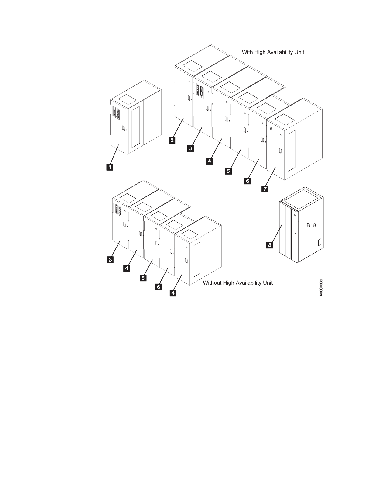
Figure 1. IBM 3494 Tape Libraries
Note: For additional 3494 configurations, see
and Planning Guide
, GA32-0279.
IBM 3494 Tape Library Introduction
The control unit frame provides full library function without the other optional
frames. Adding the optional frames to the control unit frame provides for additional
storage and tape drive capabilities. See Table 2 on page 25 for the cartridge
capacity of each frame.
Chapter 1. Introduction 3
Page 26

Functional Components
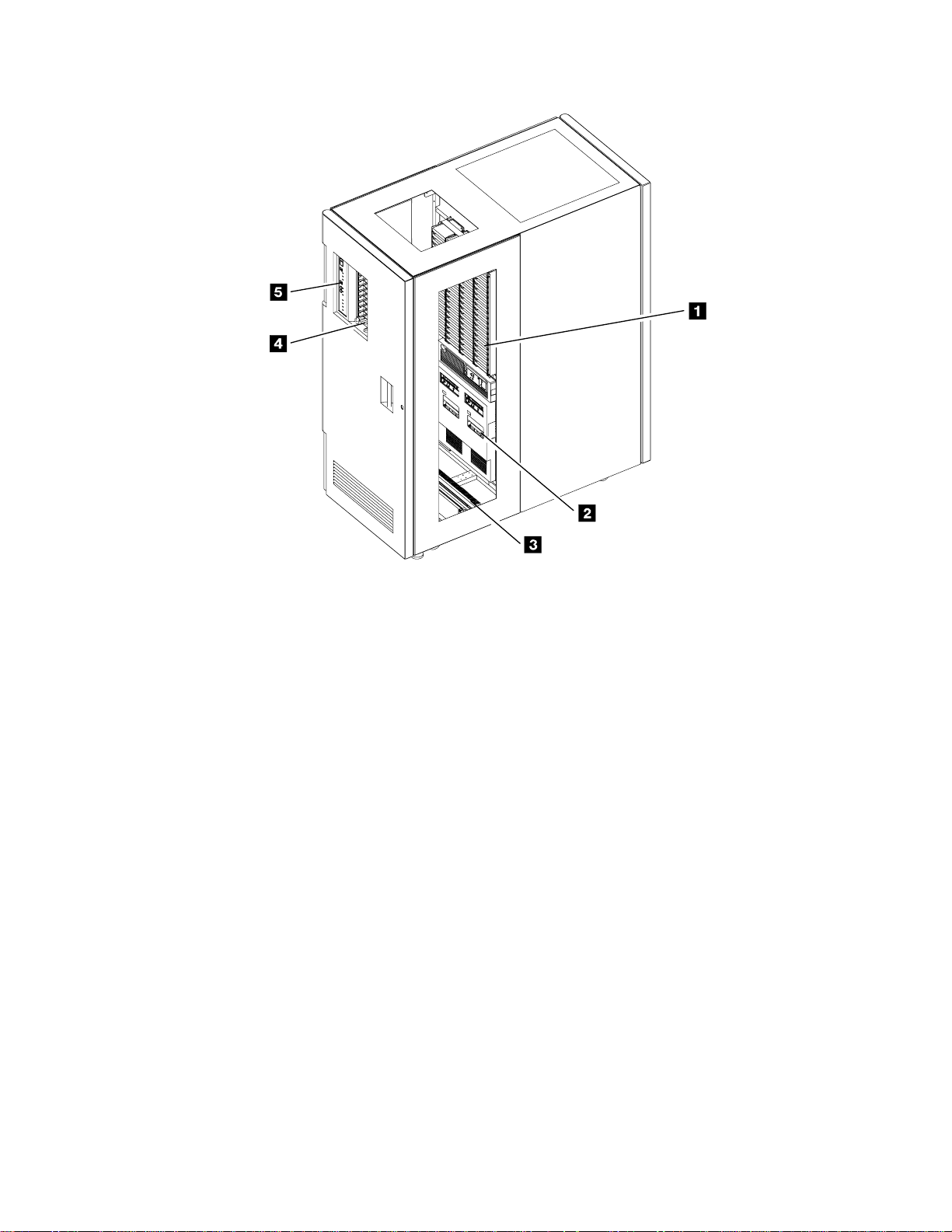
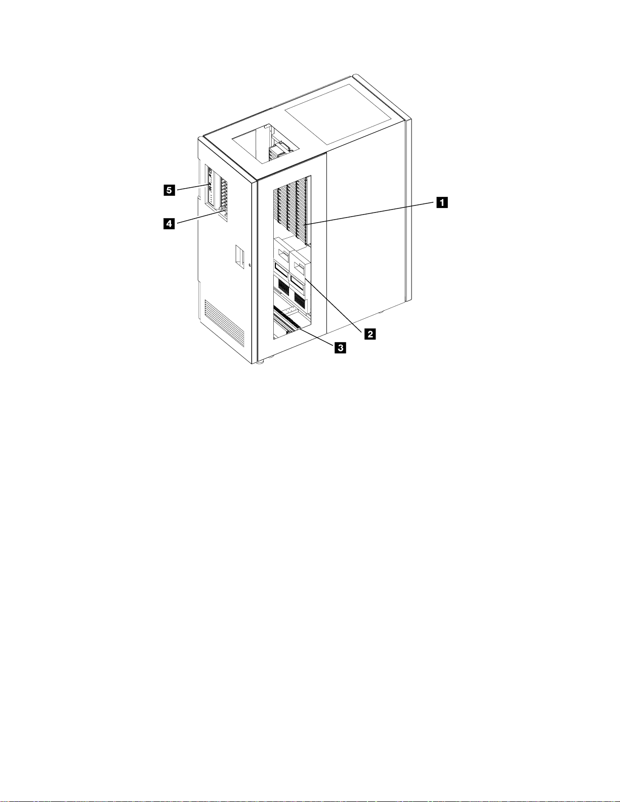
Figure 2 on page 5 and Figure 3 on page 6 show the following functional
components of the control unit frame, viewable from the front:
1 Cartridge storage cells
2 Magnetic tape subsystem
3 Rail system
4 Convenience Input⁄Output Station
|
Are located on the interior side of front doors and on the back walls of the
3494. See 1 in Figure 2 on page 5 or in Figure 3 on page 6.
The 3494 uses either the 3490E Magnetic Tape Subsystem Model C1A or
C2A, Figure 2 on page 5, 3490E Magnetic Tape Subsystem Model F1A, or
the 3590 High Performance Magnetic Tape Subsystem Model B1A, Figure 3
on page 6, with or without a 3590 Model A00 or A50 Control Unit.
The cartridge accessor is carried through the library on the rail system. The
rail system consists of two horizontal rails, one at the top and one at the
bottom.
The 3494 may have a Convenience Input⁄Output Station feature installed for
inserting or ejecting cartridges without interrupting the normal automated
operations.
Two features are available: either the ten-cartridge capacity Convenience
Input⁄Output Station as shown in Figure 2 on page 5 or the 30-cartridge
capacity Convenience Input⁄Output Station (not shown).
|
|
|
|
5 Operator panel
Note: The Convenience Input⁄Output Station feature is required for
Import/Export operations in the Model B18 VTS with the Advanced
Function Feature.
The basic operating procedures are performed from the operator panel.
4 Magstar 3494 Tape Library Operator Guide
Page 27
A06C0041
Figure 2. Control Unit Frame Functional Components, 3490E (Front View)
Chapter 1. Introduction 5
Page 28
A06O0004
Figure 3. Control Unit Frame Functional Components, 3590 (Front View)
Figure 4 on page 7 shows the following functional components of the control unit
frame, viewable from the rear:
1 Library manager
Controls all operations in the 3494. Its hardware consists of a controller,
display, pointing device, and keyboard. An optional Remote Library
Manager Console feature is also available for remote installation on a Local
Area Network (LAN) environment. During normal operations, the operator
panel controls are used to operate the 3494. The library manager is used
for error recovery, operations status, and service.
2 Cartridge storage cells
Are located on the interior side of the front doors on the 3494 and on the
back interior wall.
3 Cartridge accessor
Moves on horizontal and vertical axes, moving cartridges between the
storage cells, devices, and input and output facilities. The vision system
(barcode reader) on the cartridge accessor identifies cartridges.
4 Picker
Is the part of the cartridge accessor that actually picks cartridges. The
picker comes standard with one gripper installed or two grippers if the
optional Dual Gripper feature is installed.
5 3590 Model A00 or A50 Control Unit
is the 3590 Model A00 or A50 Control Unit.
6 Magstar 3494 Tape Library Operator Guide
Page 29
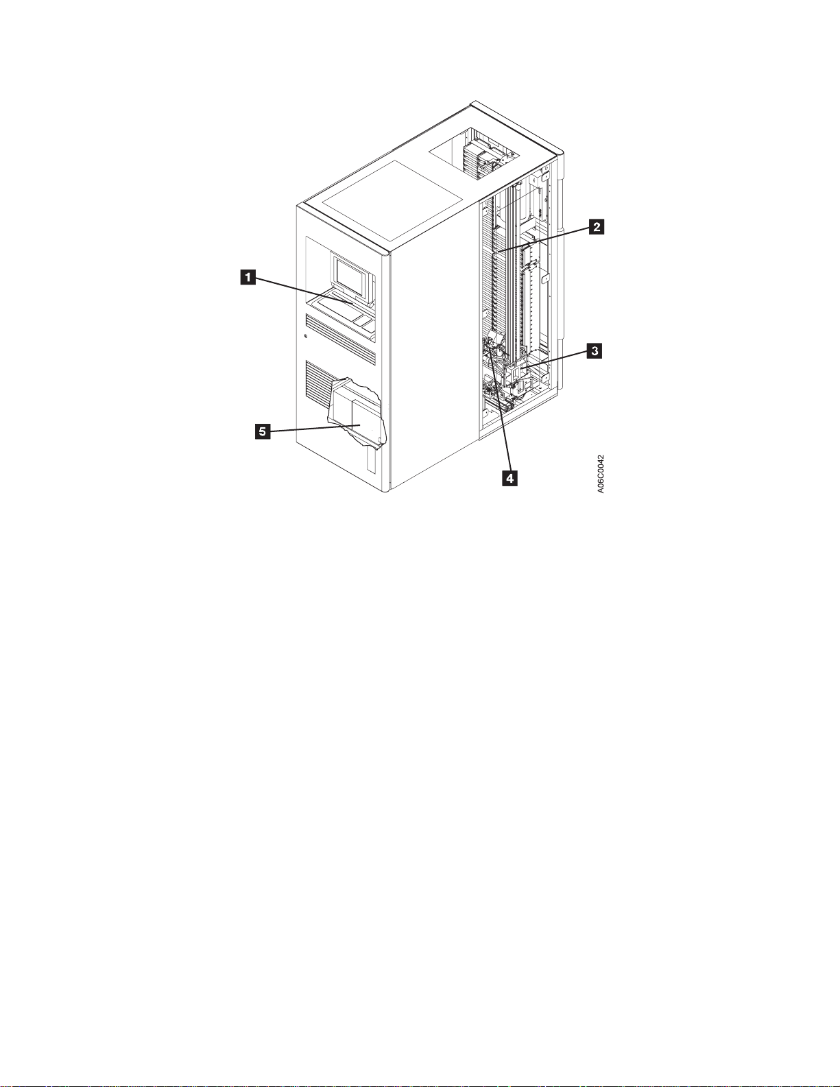
Figure 4. Control Unit Frame Functional Components (Rear View)
Figure 5 on page 8 shows the functional components of the storage frame, viewable
from the front:
1 Cartridge storage cells
Are located on the interior side of the front door and on the back wall of the
frame.
2 Rail system
The cartridge accessor is carried through the library on the rail system
installed in each frame. The rail system consists of two horizontal rails, one
at the top and one at the bottom of the frame.
Chapter 1. Introduction 7
Page 30
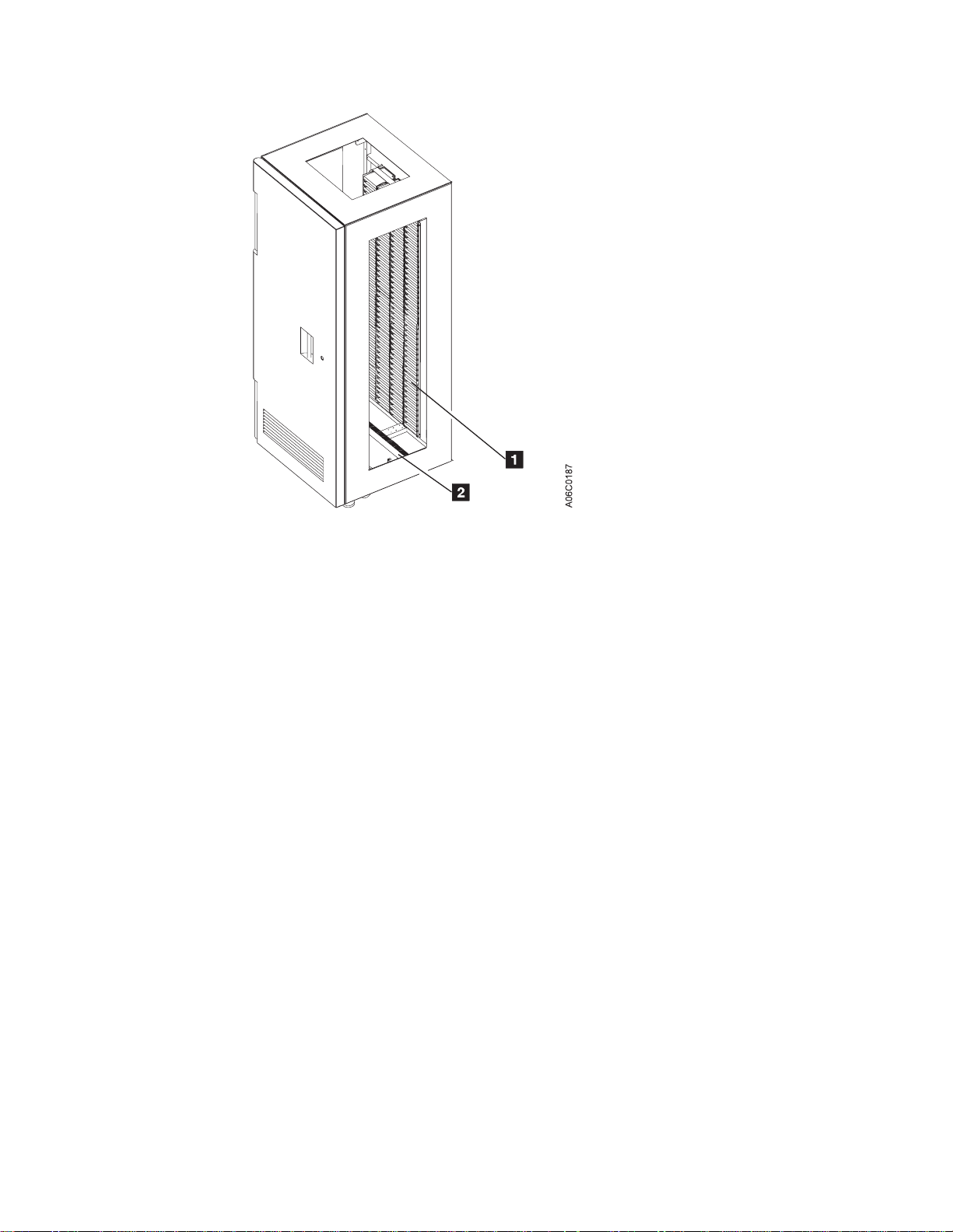
Figure 5. Storage Frame Functional Components (front)
Figure 6 on page 9 shows the functional components of the drive unit frame with
four 3590 tape subsystems and a 3590 Model A00 or A50 Control Unit, viewable
from the front:
1 Cartridge storage cells
Are located on the interior side of the front door and on the back wall of the
frame.
2 Magnetic tape subsystems
The magnetic tape subsystems that can be installed in a drive frame are
the 3490E Magnetic Tape Subsystem Model C1A or C2A (not shown), the
3590 Magnetic Tape Subsystem Model F1A (one or two per frame), or the
3590 High Performance Magnetic Tape Subsystem Model B1A with or
without a 3590 Model A00 or A50 Control Unit.
3 Rail system
The cartridge accessor is carried through the library on the rail system
installed in each frame. The rail system consists of two horizontal rails, one
at the top and one at the bottom of the frame.
8 Magstar 3494 Tape Library Operator Guide
Page 31

Figure 6. Drive Unit Frame Functional Components (front)
Figure 7 on page 10 shows the functional components of the drive unit frame with
four 3590 tape subsystems and a 3590 Model A00 or A50 Control Unit, viewable
from the rear (shown with rear door removed):
1 Cartridge storage cells
Are located on the interior side of the front door and on the back wall of the
frame.
2 Rail system
The cartridge accessor is carried through the library on the rail system
installed in each frame. The rail system consists of two horizontal rails, one
at the top and one at the bottom of the frame.
3 Power control compartment
Power to all components in the frame is distributed through the power
control compartment.
4 3590 Model A00 or A50 Control Unit
The 3590 Model A00 or A50 Control Unit consists of a RISC processor and
associated adapter cards.
5 3590 tape subsystems
From one to four 3590 magnetic tape subsystems can be installed along
with the 3590 Model A00 or A50 Control Unit. From one to six 3590
magnetic tape subsystems can be installed without a Model A00 or A50
Control Unit (not shown).
Chapter 1. Introduction 9
Page 32

Figure 7. Drive Unit Frame Functional Components (rear)
Figure 8 on page 11 shows the functional components of the Model B16 Virtual
Tape Server frame, viewable from the front:
1 Cartridge storage cells
Are located on the interior side of the front door and on the back wall of the
frame.
2 Rail system
The cartridge accessor is carried through the library on the rail system
installed in each frame. The rail system consists of two horizontal rails, one
at the top and one at the bottom of the frame.
10 Magstar 3494 Tape Library Operator Guide
Page 33

Figure 8. Model B16 Virtual Tape Server Functional Components (front)
Figure 9 on page 12 shows the functional components of the Model B16 Virtual
Tape Server frame, viewable from the rear (shown with rear door removed):
1 Cartridge storage cells
Are located on the interior side of the front door and on the back wall of the
frame.
2 Rail system
The cartridge accessor is carried through the library on the rail system
installed in each frame. The rail system consists of two horizontal rails, one
at the top and one at the bottom of the frame.
3 Power control compartment
Power to all components in the frame is distributed through the power
control compartment.
4 Virtual Tape Server controller
The Virtual Tape Server controller consists of a RISC processor and
associated adapter cards.
5 Disk storage
Disk storage holds the contents of the Tape Volume Cache and is managed
by the Virtual Tape Server controller. Two or four disk storage features are
installed in a Virtual Tape Server control unit frame.
Chapter 1. Introduction 11
Page 34

Figure 9. Model B16 Virtual Tape Server Functional Components (rear)
Figure 10 on page 13 shows the Model B18 Virtual Tape Server frame, viewable
from the front:
12 Magstar 3494 Tape Library Operator Guide
Page 35

Figure 10. Model B18 Virtual Tape Server (front)
Figure 11 on page 14 shows the functional components of the Model B18 Virtual
Tape Server frame, viewable from the rear (shown with rear door removed):
1 Disk storage
Disk storage holds the contents of the Tape Volume Cache and is managed
by the Virtual Tape Server controller. One to four disk storage features may
be installed in a Model B18 VTS.
2 Virtual Tape Server controller
The Virtual Tape Server controller consists of a RISC processor and
associated adapter cards.
3 Power control compartment
Power to all components in the frame is distributed through the power
control compartment.
Chapter 1. Introduction 13
Page 36

Figure 11. Model B18 Virtual Tape Server Functional Components (rear)
Figure 12 on page 15 shows the following functional components of the Model HA1
Left Service Bay from the right front:
1 Cartridge storage cells
Are located on the interior side of the front doors on the 3494 and on the
back interior wall but are for service use only.
2Barrier door
Used by service personnel to separate the service bay from the main aisle
of the 3494. This allows for concurrent service of the accessor and the
associated hardware.
14 Magstar 3494 Tape Library Operator Guide
Page 37

Figure 12. Model HA1, Left Service Bay Functional Components (right front)
Figure 13 on page 16 shows the following functional components of the Model HA1,
Right Service Bay from the right front:
1 Cartridge storage cells
Are located on the interior side of the front doors on the 3494 and on the
back interior wall but are for service use only.
2 Barrier door
Used by service personnel to separate the service bay from the main aisle
of the 3494. This allows for concurrent service of the accessor and the
associated hardware.
3Hot standby library manager
The Hot Standby Library Manager can take control of all operations in the
3494. Its hardware consists of a controller, display, pointing device, and
keyboard. An optional Remote Library Manager Console feature is also
available for remote installation on a Local Area Network (LAN)
environment.
Hot standby accessor or second active accessor (not visible)
Moves on horizontal and vertical axes, moving cartridges between the
storage cells, devices, and input and output facilities. The vision system
(barcode reader) on the cartridge accessor identifies cartridges. This
accessor can be controlled by either Library Manager.
Picker (not visible)
The part of the cartridge accessor that picks the cartridges. The picker
comes standard with one gripper installed or two grippers if the optional
Dual Gripper feature is installed.
Chapter 1. Introduction 15
Page 38

Figure 13. Model HA1, Right Service Bay Functional Components (right front)
Cartridge Input and Output Facilities
The following four types of input and output facilities are available on the 3494:
v High-capacity output facility
v High-capacity input/output facility
v Single-cell output facility
v Convenience Input⁄Output Station feature
High-Capacity Output Facility
The high-capacity output facility, if defined during installation, reserves a section of
the cartridge storage area for high-capacity output of cartridges.
Library Type Cartridge Capacity
Single Gripper 10, 20, 40, 80, or a full door
Dual Gripper 10, 20, 36, 72, or a full door
The cartridge cells are located inside the control unit frame on wall 2, column A,
starting with cell 1 (expressed as location 2 A 1) 2 (see Figure 14 on page 17).
See “Removing Ejected Cartridges from the High-Capacity Output Facility” on
page 82 for operating instructions.
High-Capacity Input/Output Facility
A High-Capacity Input/Output facility may be defined for the inside wall (drive side
walls) so that both inserts (Input) and ejects (Output) can be performed. Storage
Unit (SU), B16 or Drive unit (DU) walls, 3 through 31 (odd numbered walls only),
16 Magstar 3494 Tape Library Operator Guide
Page 39

can be configured as High-Capacity Input/Output. An SU, or B16, configured as
High-Capacity I/O can contain 100 (upper half) or 200 (whole wall) cells. A DU
configured as High-Capacity I/O contains from 50 (six 3590 drives) to 135 (two
3590 drives) and uses all available cells in the wall. Only a single wall can be
configured at any time (single High-Capacity input/output facility).
Single-Cell Output Facility
If a Convenience Input⁄Output Station is not installed and a high-capacity output
facility or high-capacity input/output facility is not defined, a single cell in the door of
the control unit frame is provided for output. The location of the single cell 1 as
shown in Figure 14 is defined as 2 A 1. If the optional dual gripper feature is
installed, the single cell location is 2 A 3. Any empty and unassigned cell can be
used for input operations. See “Removing an Ejected Cartridge from the Single-Cell
Output Facility” on page 81 for operating instructions.
Figure 14. Control Unit Frame Cartridge Storage Cells
Convenience Input⁄Output Station Feature
If the Convenience Input⁄Output Station feature is installed, you can add or remove
from ten to 30 cartridges from the library without interrupting the normal operations
of the library. See “Using the Convenience Input⁄Output Station Feature to Insert
Cartridges” on page 78 and “Removing Ejected Cartridges from the Convenience
Input⁄Output Station Feature” on page 82 for the operating instructions for this
feature.
Chapter 1. Introduction 17
Page 40

|
|
|
|
Cartridge Tape
There are two modes of operation for the Convenience Input⁄Output Station while in
Input mode: Insert, and Import. If one or more Virtual Tape Servers are
Import/Export capable, then the Convenience Input⁄Output Station will be in Import
mode.
The 3494 is designed to automate the storage and movement of the Cartridge
System Tape, the Enhanced Capacity Cartridge System Tape, and the 3590 High
Performance Cartridge Tape.
Note: The 3590 High Performance Cartridge Tape can only be used on 3590 High
Performance Magnetic Tape Subsystems. The Cartridge System Tape and
the Enhanced Capacity Cartridge System Tape can only be used on 3490E
Magnetic Tape Subsystems.
The 3494 supports an intermix of the Cartridge System Tape, the Enhanced
Capacity Cartridge System Tape, and the High Performance Cartridge Tape
depending on the model of tape drive subsystem installed. The Enhanced Capacity
Cartridge System Tape is visually distinguished from the Cartridge System Tape by
its two-color (gray and white) plastic case. The High Performance Cartridge Tape is
visually distinguished from the Enhanced Capacity Cartridge System Tape and the
Cartridge System Tape by its black plastic case, blue plastic inserts, and blue
leader block.
Figure 15 on page 19 shows the Cartridge System Tape 1, Enhanced Capacity
Cartridge System Tape 2, and the High Performance Cartridge Tape 3. Note the
blue plastic inserts of the High Performance Cartridge Tape cartridge and the
placement of the media-type label (either 1, E, or J).
The vision system identifies the type of cartridge during an inventory or insert
operation by reading a separate, media-type label to distinguish between the three
types of cartridges. A standard Cartridge System Tape is identified by a media-type
label with the character 1. The Enhanced Capacity Cartridge System Tape is
identified with the character E. The High Performance Cartridge Tape cartridge is
identified with the character J. See “Unlabeled Tape Facility” on page 22 for more
information.
Notes:
1. If both 3490 and 3590 drive types are installed in the 3494, all cartridges should
have a label in the seventh character position. See Figure 15 on page 19.
2. The media type of the cartridge can be determined in several ways:
v The most desirable method is for the vision system to read the seventh
character on the label.
v If users have cartridges without the seventh character, they may assign
volser ranges (see “Volser Range for Media Types” on page 161) for
determining the media type. If the vision system does not successfully read a
seventh character, the library manager checks the volser read against the
established volser ranges. If the volser is found, the media type that is
associated with the range is used.
v Additionally, a default media type can be set during a teach operation. The
default media type is used for the cartridge if the vision system cannot
18 Magstar 3494 Tape Library Operator Guide
Page 41

successfully read a seventh character and there is no volser range that
includes this volser. This method is typically used for Cartridge System Tape
without the seventh character.
If none of the above methods are successful at assigning a media type, the
cartridge is ejected, and an operator intervention is set.
The vision system also identifies the cartridge volser during an inventory or insert
operation by reading the external labels on the cartridge. The media-type and volser
information is then stored in the database in the library manager.
Blue
Gray
Figure 15. Cartridge System Tape Identification
Gray
Tape Cartridge Requirements
Figure 16 on page 20 shows the cartridge system tape requirements:
v The tape cartridge 1 should have an external label 2 applied.
v The file-protect selector 3 must be set to the correct position for the volume’s
intended purpose (see “Cartridge File Protection” on page 20).
v The leader block 4 on the tape cartridge must be seated before inserting the
cartridge into the library.
v The tape cartridge is inserted into the library cartridge storage cells in the
direction 5 shown so that the external label is readable when stored.
Note: When inserting the tape cartridges into the Convenience Input⁄Output
Station feature, insert the external label side first in the direction 6.
White
Black
0003
A06O
Chapter 1. Introduction 19
Page 42

Figure 16. Cartridge System Tape
Cartridge File Protection
Each tape cartridge includes a file-protect selector 3 (see Figure 16) that, when
set to the file-protect position, prevents writing on or erasing data from the tape.
Normally, cartridges used in the 3494 should not be manually file-protected. If
required, software can be used to file-protect the cartridges. This allows the host,
when appropriate, to identify a cartridge that no longer contains current data and
can be a scratch cartridge. Do not file-protect scratch cartridges because new data
cannot be written to file-protected cartridges. For additional information, refer to
Care and Handling of the IBM Magnetic Tape Cartridge
Cartridge System Tape Labels
Each tape cartridge in the 3494 must have external labels that are operator- and
machine-readable. The labels identify the volume serial number (volser) and type of
cartridge. Currently supported labels are Tri-Code, available from Wright Line
Corporation, Tri-Optic, available from Engineered Data Products, and labels from
Information Data Storage.
Note: The only exception for the label requirement is when using the Unlabeled
Tape Operations function. See “Unlabeled Tape Facility” on page 22 for more
information.
The volser label contains up to six characters, and the separate media-type label
provides a seventh character for media-type identification. A volser can contain one
to six characters, with blanks padded on the right for a volser with fewer than six
characters. Characters can be uppercase A–Z and numerics 0–9. Each tape
cartridge typically has a separate single-character media-type label that identifies
the cartridge type. The media-type label character for a Cartridge System Tape is 1,
for an Enhanced Capacity Cartridge System Tape is E, and for High Performance
Cartridge Tape is J.
Note: See “Cartridge Tape” on page 18 for the process used to determine the
cartridge media type.
20 Magstar 3494 Tape Library Operator Guide
Page 43

The external labels on the cartridges identify the cartridges to the 3494. Host
control software in some operating environments requires that internally written
labels on volumes correspond to external volsers. IBM recommends that
correspondence of external and internal cartridge labels be verified by library control
software as part of mount processing. Cleaner cartridges must also have operator
and machine-readable external labels to identify each cartridge.
High Performance Cartridge Tapes (HPCT) managed by the VTS are automatically
checked for the correct internal volume label and re-labeled if necessary.
Figure 17 shows the possible labeling configurations of the tape cartridges and
Table 1 shows how the library handles the different types of labeling configurations.
Blue
0002
Gray
Gray
Gray
White
Gray
White
Black
A06O
Figure 17. Cartridge System Tape Labels
Table 1. Cartridge Tape Labeling (Media type default set to Cartridge System Tape)
Media-Type
Cartridge Type Color
Label Handled as:
1 Cartridge System Tape Gray Not present Cartridge System
Tape(default, see note)
2 Cartridge System Tape Gray Present (1) Cartridge System Tape
3 Enhanced Capacity
Cartridge System Tape
4 Enhanced Capacity
Cartridge System Tape
5 High Performance
Cartridge Tape
Gray and
white
Gray and
white
Black with
blue leader
Not present Cartridge System
Tape(default, see note)
Present (E) Enhanced Capacity
Cartridge System Tape
Present (J) High Performance Cartridge
Tape
block and
identification
notches
Note: The default could be Enhanced Capacity Cartridge System Tape or High
Performance Cartridge Tape instead of Cartridge System Tape; refer to “Operational Status”
on page 111.
Chapter 1. Introduction 21
Page 44

Unlabeled Tape Facility
Note: Do not use this function with cartridges with machine-readable labels.
Unlabeled tape operations are designed to allow the operator to occasionally insert
volumes into the 3494 that do not have external machine-readable volser and
media-type labels. Once inserted through the unlabeled tape facility, the volumes
may be used in the same manner that regular, properly labeled volumes are used,
with the exception of any operations that require the external machine-readable
label to be read.
It is not recommended that volumes to be managed by the VTS be inserted using
this facility. However, in the event the external label on a stacked volume becomes
damaged, this facility can be used to re-insert the volume until its external label can
be replaced.
To use the unlabeled tape facility, the operator selects the Insert Unlabeled
Cartridges command from the Commands pull-down on the library manager. The
operator then provides the volser and media-type information requested. The
unlabeled tapes are then placed into the Convenience Input⁄Output Station. The
library will then move the cartridges from the Convenience Input⁄Output Station to
their designated cells. The library manager database is updated to indicate the
location of the cartridges using the volser and media-type information provided. All
hosts are notified that the cartridges have been added to the insert category just as
regular, properly labeled volumes are handled.
Inventory update operations only verifies that all unlabeled cartridges are in cells
that previously contained unlabeled cartridges.
Note: This facility should not be used for a large number of cartridges or for
Cartridge Labeling
To apply an external volser cartridge label, do the following:
1. Examine the label before you apply it to the cartridge. Do not use the label if it
2. Remove the label from the label sheet carefully so you do not stretch the label
3. Line up either end of the label with the lip of the label indentation. Be sure to
4. Apply the label parallel to the long edge of the indentation. Do not pull the label
5. Smooth out the label so that no wrinkles or bubbles exist on the label. Use light
6. Verify that the label is smooth and parallel and has no roll-up or roll-over.
cartridges that are stored in the library for a long time. Refer to “Insert
Unlabeled Cartridges” on page 184 for additional information.
has voids or smears in the printed characters or bar codes.
or cause the edges to curl.
position the bar-code side of the label toward the inside edge of the indentation.
Do not allow the label to roll up or over this lip; the label must be flat within the
cartridge indentation surface. Apply the label either from the top or from the
bottom. Carefully position the label within the indentation on the end of the
cartridge away from the leader block. The machine-readable bar code must face
to the right.
excessively because it will stretch.
finger pressure to smooth the label and secure it to the cartridge.
22 Magstar 3494 Tape Library Operator Guide
Page 45

The label must be flat to within 0.5 mm (0.2 in.) over the length of the label and
have no folds, missing pieces, or smudges. Figure 18 shows the correct position
of the label on the cartridge case.
No Roll- up or Roll-o ver
No Wrinkles
No Bubbles
No Stretch
Parallel to Edge
Figure 18. Cartridge Label Position
Do not place a new label over an existing label. Remove an old label by slowly
pulling it at a right angle to the cartridge case. Do not reuse a label.
No other labels can be placed on the same surface as the external volser cartridge
label. Labels on other surfaces of the cartridge must not interfere with the cartridge
accessor’s gripper or the tape drives, and should not be machine readable as that
may interfere with the ability of the vision system to read the volser and the
media-type label.
Media-Type Labeling
Media-type labels are applied in two different ways as follows:
v If the cartridge has no separate area below the volser label (for example, an
indented area), place the media-type label in line and just below the volser label.
v If the cartridge has a separate area (for example, an indented area)
approximately 2 mm (0.08 in.) below the &vol label, place the media-type label in
the separate area.
The label must be flat to within 0.5 mm (0.2 in.) over the length of the label and
have no folds, missing pieces, or smudges. The label must not be rotated more
than 3° from being parallel with the edges of the cartridge.
No Roll- up or Roll-o ver
A06C0035
Chapter 1. Introduction 23
Page 46

Cartridge Storage Cells
The cartridge cell locations are named so the operator can find the cartridges
during Manual mode operation. The cell name consists of three values: a wall
number, a column letter, and a row number. For example, Figure 19 shows cell
location 2 A 1.
Figure 19. Cartridge Storage Cell Names
Figure 20 on page 25 shows the cartridge storage cell labeling.
Wall number
The wall numbers 3 that are even-numbered represent the walls on the
front doors of the library. The wall numbers that are odd-numbered
represent the walls on the rear of the library.
Column letters
The column letters 1 range from A to E and are labeled from left to right.
Note: The control unit frame has only four columns; therefore, the letter
Row numbers
The row numbers 2 range from 1 to 20 or from 1 to 40, depending on the
frame and the wall. The numbers start with 1 at the top of the frame and
end at 40 for the lowest row.
range is from A to D.
24 Magstar 3494 Tape Library Operator Guide
Page 47

2
A
B
2
3
4
5
6
Figure 20. Cartridge Storage Cell Labeling
Reserved Cartridge Storage Cells
The library reserves certain cells within the library for functions that the operator
does not actively control.
06C0047
In non-high availability models these locations are Error Recovery Cells 1 A 1 (1 A 3
instead of 1 A 1 if the optional Dual Gripper feature is installed) and CE cartridge
cell 1 A 20. If both 3490E and 3590 tape subsystems are present, CE cartridge 1 A
19 is also reserved. These are used for error recovery cell and for service
cartridges. In high availability models, these locations are Error Recovery Cell 1 A 1
and 1 A 2 or 1 A 3 and 1 A 4 if the Dual Gripper Feature is installed. CE cartridge
cells are in the service bays.
Cartridge Storage Capacity
Table 2 shows the cartridge capacity of each frame.
Table 2. Magstar 3494 Cartridge Capacity
Model or Frame
Model L10, L12, or L14 240 (see notes 1, 4, 5,
Model S10, FC 5400 400 360
Without
Dual Gripper
and 6)
With
Dual Gripper
216 (see notes 2, 4, 5,
and 6)
Chapter 1. Introduction 25
Page 48

Table 2. Magstar 3494 Cartridge Capacity (continued)
Without
With
Model or Frame
Model D10
(without 3490 Model CxA/F1A)
Model D10, FC 5300
(with 3490 Model CxA/F1A)
Model D12, FC 5500 400 360
Model D12, FC 5302
(with one or two 3590 Models B1A)
Model D12, FC 5302, FC 5502
(with three or four 3590 Models B1A)
Model D12, FC 5302 (with RPQs), FC
5502 (with RPQ)
(with five or six 3590 Models B1A)
Model D14
(without 3590 Model B1A)
Model D14, FC 5304
(with one or two 3590 Models B1A)
Model D14, FC 5304 (with RPQ)
Dual Gripper
400 360
300 270
335 305
290 260
250 230
400 360
345 305
305 275
Dual Gripper
(with three or four 3590 Models B1A)
Model B16, or FC 5500 400 360
Model B18 0 0
Model HA1 (service bays) 0 0
Notes:
1. The optional Convenience Input⁄Output Station feature reduces the cartridge capacity by
30 cartridges (FC 5210) or 80 cartridges (FC 5230).
2. With dual grippers installed, the optional Convenience Input⁄Output Station feature
reduces the cartridge capacity by 26 cartridges (FC 5210) or 72 cartridges (FC 5230).
3. Selecting the high-capacity input/output station facility reduces the cartridge capacity,
depending on the options chosen (see “High-Capacity Input/Output Facility” on page 16).
4. One cell is reserved for ejecting cartridges if the optional Convenience Input⁄Output
Station feature is not installed and the high-capacity output facility is not defined.
5. A maximum of two cells are reserved for certain service representative functions. When
the high availability unit is installed, there are no cells reserved in the L1x unit for
service functions.
6. One cell is reserved for error-recovery operations for configurations without the high
availability unit and two cells are reserved for error-recovery operations for
configurations with the high availability unit.
26 Magstar 3494 Tape Library Operator Guide
Page 49

Library Manager
User Interface
The library manager processes all requests and control functions in the library.
The user interface enables the operator to obtain information about the operation of
the library and instructs the library manager to perform specific tasks through the
use of the library manager console (display, keyboard, and pointing device).
Password-protection for the level of authorization is optional. The user interface
recognizes the following three authorization levels:
General operator
A general operator performs the day-to-day basic interactions with the
library. This is generally limited to inquiries about the library status or to
perform cartridge insert and eject operations. A general operator has a
limited level of authorization.
System administrator
A system administrator is an operator with additional training on the
management of not only the library but of the data also. The system
administrator typically handles the initial installation of volumes into the
library and the problem resolution with volumes during operation. The
system administrator has authorization access to all functions of the library,
except for those uniquely related to the service and repair of the library.
Service representative
Password-Protection
|
|
|
The following functions of the library manager can be protected by a password if
the customer chooses to use password-protection:
v Service menu
v Inventory new storage
v Re-inventory complete system
v Emergency power off (EPO) recovery
v Shutdown
v Keyboard and display lockup
v System administrator to unlock
v Unlock keyboard and display
v Service Access
v Cancel VTS Export/Import
Each time a user enters a part of the application where a password is required,
then enters a password, a log entry is made at the library manager. Exiting a
protected menu also creates a log entry. See “System Administrator Password” on
page 200 for more information.
The service representative has full authorization access to all functions of
the library.
Chapter 1. Introduction 27
Page 50

Database
The library manager creates and maintains a database that contains the
configuration of the library, the physical location information for all the elements of
the library serviced by the cartridge accessor, the inventory of the physical cartridge
volumes and logical volumes managed by a VTS, and information about their use
and current status, and the status of each 3490E/3590 device and virtual device. As
operations progress through the library, the database is dynamically updated on the
disk drive to reflect the current status of the library.
High Availability (Model HA1)
If the high availability model is installed, a second library manager is provided in the
right-hand service bay. Each library manager contains two hard (disk) drives, a
primary and secondary disk. Under normal operation, one library manager is the
active library manager and the other library manager is the standby library manager.
The active library manager, on its primary disk, creates and maintains the database,
which is dynamically updated to reflect the current status of each library. The
standby library primary disk contains a back-up of the database, which is also
dynamically updated to reflect the current status of the library.
If the active library manager fails, the standby library manager automatically
becomes the active library manager and takes control of operations. A new backup
database is then created on the active library manager’s secondary disk drive. The
new active library manager runs in degraded mode until the failing library manager
is repaired. This allows continued operation of the 3494.
Database Information Available to a Host
The library manager maintains information in its database that may be requested
through a host. The form of the particular host request is dependent on the host
environment. The following information is available through the host:
Category inventory data
Records for 100 volumes in the library for the category specified, starting
after the sequence number specified by the request. If fewer than 100
volumes are in the category, all of the remaining records are returned. Each
record contains the current status and media-type for a volume in the
inventory.
Device data
Information about any particular device within the library. This information
includes the device states, volser, and category of the mounted cartridge.
Expanded volume data
More detailed information about the current status and media-type for a
specific volume than the volume data information request. It does not
provide physical location information for the volume.
Inventory volume count
The number of volumes in the library for either the entire inventory or a
specified category.
Inventory data
Records for 100 volumes in the library, starting after the volume specified
by the request. If fewer than 100 volumes remain in the library, all of the
28 Magstar 3494 Tape Library Operator Guide
Page 51

remaining records are returned. Each record contains the current status and
media-type for a volume in the inventory.
Library information data
The current operational status of the library and basic library configuration
data with information on installed options.
Reserved category data
Information about the categories that have already been reserved within the
library.
Statistical data
Information about the current workload and performance characteristics of
the library.
Volume data
Information about the current status and media-type of specified volume.
Category attribute data
Information about the category attributes, for example, name.
Operational Modes and States
The 3494 operates in one of the following modes:
Auto
Pause
Manual
The operational states of the 3494 are as follows:
Online
Offline
For a detailed description of these operations, see “Chapter 4. Operational Modes
and States, and Informational States” on page 63.
Chapter 1. Introduction 29
Page 52

30 Magstar 3494 Tape Library Operator Guide
Page 53

Chapter 2. Controls and Indicators
The controls and the indicators for the 3494 are described in this chapter.
The 3494 is controlled through the use of the operator panel 1 (see Figure 21) on
the front of the control unit frame. The Convenience Input⁄Output Station feature 2
is also on the front of the control unit framenext to the operator panel, if it is
installed. The handles 3 for opening the doors on the front of the frames are
located next to the door locks 4. The library manager is in the rear of the control
unit frame. The tape subsystem controls are on the front of the drives inside the
control unit frame and drive unit frame.
Note: Two keys are supplied with the 3494. One key is used by the operators and
service personnel to open the front doors on the library. The other key is for
use by service personnel to open the doors on the back of the library.
A06C0033
Figure 21. Control Unit Frame Front Door
© Copyright IBM Corp. 1993, 1999 31
Page 54

Operator Panel
The 3494 operator panel is mounted on the front door of the control unit frame.
Normal operation of the 3494 is controlled through the use of this operator panel.
Power Controls and Status Indicators
See Figure 22 on page 33 for the locations of the controls and indicators.
1 Unit Emergency switch
The Unit Emergency switch turns off power to the 3494 immediately and
should only be used in an emergency. The Unit Emergency switch must be
in the on position for the 3494 to be powered on.
Note: If the 3494 Library has more than eight frames, or has the optional
High Availability Model Service Bays, a second unit emergency
switch is located at the right end of the Library. Either switch can be
used to immediately turn off power.
Note: The 3494 Library Unit Emergency switches do not turn off power to
the attached stand-alone Model B18 Virtual Tape Server.
2 Unit Power switch
The Unit Power switch turns power on and off to the components inside the
3494. The Unit Power switch is used to power on and off the 3494 under
normal conditions. Using the Unit Power switch to turn off power to the
3494 allows the library manager, Virtual Tape Servers, tape control units,
and tape drives to shut down in an orderly manner.
3 Rack Power Ready LED
The Rack Power Ready light-emitting diode (LED), when lit, indicates the
AC power is on in the 3494 control unit.
4 System Power Ready LED
The System Power Ready LED, when lit, indicates the AC power is on to
the control units and drive units inside the 3494.
5 Power Off Pending LED
The Power Off Pending LED, when flashing, indicates the power to the
3494 is being turned off.
6 Local Remote power switch
The Local Remote power switch allows the library’s power to be controlled
by the switches on the operator panel (local) or through an AS/400 host
(remote) if the Local Remote Power Feature is installed. The Local Remote
switch must be in the local position if the remote power feature is not
installed.
Attention: Pressing the Local Remote switch to the remote position, if the
Local Remote Power feature is not installed, causes the 3494 to power off.
Motion Controls and Status Indicators
See Figure 22 on page 33 for the locations of the controls and indicators.
7 Auto mode switch and status LED
The Auto mode motion control switch allows the operator to place the
library into Auto mode. The LED flashes during the mode transition and
32 Magstar 3494 Tape Library Operator Guide
Page 55

remains lit when in Auto mode. If the mode transition cannot be completed,
the Intervention Required LED will light.
8 Pause mode switch and status LED
The Pause mode motion control switch allows the operator to place the
library into Pause mode. The LED flashes during the mode transition and
remains lit when in Pause mode. If the mode transition cannot be
completed, the Intervention Required LED will light.
9 Intervention Required LED
The Intervention Required LED, when lit, indicates operator interventions
are required. See “Operator Intervention” on page 199 for instructions to
perform operator interventions.
Figure 22. Operator Panel without Convenience Input⁄Output Station Feature
Convenience Input⁄Output Station Status Indicators
If the Convenience Input⁄Output Station feature is installed on the 3494, four
additional status lights are present on the operator panel. See Figure 23 on page 34
for the locations of the controls and the indicators.
1 Input Mode
The Input Mode LED, when lit, indicates that cartridges are in the
Convenience Input⁄Output Station and the station is in Input mode.
2 Output Mode
The Output Mode LED, when lit, indicates that cartridges are being ejected
from the library into the Convenience Input⁄Output Station.
3 Unload Required
The Unload Required LED, when lit, indicates that the Convenience
Input⁄Output Station has ejected cartridges that need to be removed.
Chapter 2. Controls and Indicators 33
06C0065
Page 56

4 Input⁄Output Locked
The I⁄O Locked LED, when lit, indicates that the Convenience Input⁄Output
Station station is locked and being used by the cartridge accessor.
5Convenience Input/Output Station Operation Tab
The Convenience Input⁄Output Station operation tab is used to open the
Convenience Input⁄Output Station door when the door is unlocked (when
the I⁄O Locked LED is not lit).
Library Manager
06C0064
Figure 23. Operator Panel with Convenience Input⁄Output Station Feature
The library manager display 1 (see Figure 24 on page 35) and keyboard (with
pointing device) 2 are located in the rear of the control unit frame. The library
manager is used to perform system administrator activities and advanced operator
activities. The brightness and contrast controls for the library manager display are
located on the back of the display. An optional Remote Library Manager Console
feature is also available for installing in a remote location on a LAN environment.
The library manager display is shut off by the operating system software when there
has been no activity by the operator. This “snooze” function is provided to conserve
power and increase the reliability of the display hardware. If the library is powered
on and the display is off, the operator can press any key on the keyboard to
activate the display.
See “Selections with the Pointing Device” on page 92 for a detailed description on
using the pointing device. The optional High Availability Model, Service Bay B, is
similar in looks and function.
34 Magstar 3494 Tape Library Operator Guide
Page 57

A06C0059
Figure 24. Library Manager
3490 Tape Subsystem Controls for Models C10, C11, C1A, C22, and C2A
The 3490E Model CXA control unit operator panel 1 and the 3490E Model CXA
drive unit operator panel 2 (see Figure 25 on page 36) are accessible to the
operator by opening the front door of the frame containing the tape subsystem to be
accessed.
When 3490E subsystems are attached to the 3494, the following 3490E functions
change:
Drive control
The loading and the unloading of volumes are controlled by the library
manager. The 3490E subsystem communicates with the library manager to
update the database with the drive status and the cartridge location
information.
Message displays
The library manager controls which messages are displayed to prevent the
messages from getting out of synchronization with the library manager
during Manual mode operations.
Attention interrupt
The library manager can use the communication path to the 3490E
subsystems to send information to the host.
For more information on 3490E controls and indicators, see
IBM 3490 Magnetic
Tape Subsystem Enhanced Capability Models C10, C11, C1A, C22, and C2A
Chapter 2. Controls and Indicators 35
Page 58

Operator’s GuideorIBM 3490E Tape Subsystem Models F01, F1A, F11, and FC0
Installation, Planning and Operator’s Guide
.
Channel Status
Enable A
Disable A
Enable B
Disable B
Ready Unload
Figure 25. 3490E Controls and Indicators
3490 Tape Subsystem Controls for Model F1A
Wait
Error
IML
Power On
Power Off
XXXXXXXX
Protected
The 3490E Model F1A drive unit operator panel 1 is accessible to the operator by
opening the front of the frame containing the tape subsystem to be accessed.
When 3490E subsystems are attached to the 3494, the following 3490E functions
change:
Drive control
The loading and the unloading of volumes are controlled by the library
manager. The 3490E subsystem communicates with the library manager to
update the database with the drive status and the cartridge location
information.
Message displays
The library manager controls which messages are displayed to prevent the
messages from getting out of synchronization with the library manager
during Manual mode operations.
Attention interrupt
The library manager can use the communication path to the 3490E
subsystems to send information to the host.
36 Magstar 3494 Tape Library Operator Guide
Page 59

For more information on 3490E controls and indicators, see
IBM 3490E Tape
Subsystem Models F00, F01, F1A, and F11 Installation, Planning, and Operator’s
Guide.
Figure 26. 3490E Controls and Indicators for Model F1A
3590 Model B1A Tape Subsystem Controls
The 3590 Model B1A operator panel 1 (see Figure 27 on page 38) is accessible
to the operator by opening the front door of the frame containing the tape
subsystem to be accessed.
Chapter 2. Controls and Indicators 37
Page 60

A06O0001
Figure 27. 3590 Model B1A Operator Panel
When 3590 subsystems are attached to the 3494, the following 3590 functions
change:
Drive control
The loading and unloading of volumes is controlled by the library manager.
The 3590 subsystem communicates with the library manager to update the
database with the drive status and cartridge location information.
Message displays
The library manager controls which messages are displayed to prevent the
messages from getting out of synchronization with the library manager
during Manual mode operations.
Attention interrupt
The library manager can use the communication path to the 3590 Model
A00 subsystem to send information to the host.
For more information on 3590 controls and indicators, see
Performance Tape Subsystem User’s Guide
3494 Model B18 Operator Panel
The 3494 Model B18 Virtual Tape Server operator panel is mounted on the rear
door of the unit frame.
Power Controls
Figure 28 on page 39 shows the location of the power control on the Model B18
VTS.
1 Unit Emergency switch
The Unit Emergency switch turns off power to the 3494 Model B18
38 Magstar 3494 Tape Library Operator Guide
IBM 3590 High
, GA32-0330.
Page 61

immediately and should only be used in an emergency. Abrupt removal of
power in case of emergency may cause loss of customer data. The Unit
Emergency switch must be in the on position for the 3494 Model B18 to be
powered on by the associated 3494 Library.
Note: The 3494 Model B18 Unit Emergency switch will not cause power to
be removed from the associated 3494 library.
Figure 28. Model B18 Virtual Tape Server Operator Panel
3494 Model B16 Virtual Tape Server Controls
All control functions for the Model B16 Virtual Tape Server are integrated into the
library manager. See “Chapter 6. Advanced Operating Procedures” on page 85.
3494 Model B18 Virtual Tape Server Controls
All control functions for the Model B18 Virtual Tape Server, other than emergency
power control, are integrated into the library manager. For more information, see
“Chapter 6. Advanced Operating Procedures” on page 85. Refer to “3494 Model
B18 Operator Panel” on page 38 for the Unit Emergency Switch Function.
Chapter 2. Controls and Indicators 39
Page 62

40 Magstar 3494 Tape Library Operator Guide
Page 63

Chapter 3. Operational Characteristics
The operational characteristics of the 3494 are described in this chapter.
3490E/3590 Tape Subsystem Operation
The 3494 controls the loading, unloading, and affiliated operation of the tape
subsystem in the library. No operator attendance is required unless the library is
unable to recover from a subsystem problem.
In addition to existing tape subsystem error recovery, the control unit and the library
manager execute additional recovery procedures when the tape drive detects a
load, unload, or tension loss failure.
Virtual Tape Server
The IBM Magstar 3494 Model B16 or B18 Virtual Tape Server provides for a higher
utilization of 3590 tape technology than enabled by current tape controller concepts.
A Virtual Tape Server provides the improvement in utilization without impacting
current operating system or independent software vendors. The subsystem
combines the random access and high performance characteristics of disk storage
with outboard hierarchical storage management and virtual tape drives to provide
significant reductions in the number of physical cartridges, tape drives, and
automated libraries needed to store the customer tape data. The key concepts for
the architecture of the subsystem are:
v Emulation of 32 or 64 3490-type tape drives
v Tape volume cache
v Storage management of the tape volume cache
v Maintaining data fragments from copied volumes
v Fast response for non-specific mount requests
Emulation of 3490-Type Tape Drives
From a host perspective, the Virtual Tape Server subsystem looks like two or four
3490E control units, each with 16 tape drives. Each emulated drive is called a
virtual tape drive. The subsystem handles all 3490 tape commands. Emulating a
3490–type tape drive eliminates the need for host software support of a new type of
tape drive in order to utilize the capacity of 3590–type tape drives. There is no
direct relationship between a virtual tape drive and a real 3590 tape drive.
Data is written and read as if it is stored on a real Cartridge System Tape or an
Enhanced Capacity Cartridge System Tape. However, within the subsystem, data is
stored on disks. All tape read and write commands are translated to read and write
data records from or to disk storage. Tape marks are stored as special records on
the disk storage as well. Volumes residing on disk storage are called virtual
volumes.
The amount of data stored on a virtual volume is variable up to a maximum as
determined by the media type selected. Two media types are emulated (standard
Cartridge System Tape and Enhanced Capacity Cartridge System Tape); they can
hold up to 400MB or 800MB of customer data, respectively. The 3494 Model B18
© Copyright IBM Corp. 1993, 1999 41
Page 64

with the ESCON High Performance Option (EHPO) feature emulates storage of up
to 2.4 GB (3:1 compression) on the virtual Enhanced Capacity Cartridge System
Tape.
All host interactions with data in a Virtual Tape Server subsystem are through virtual
volumes and associated virtual tape drives; there is no direct access to the data on
a physical cartridge or drive.
Tape Volume Cache
The size of the disk storage is large enough so more virtual volumes can be
retained in it than just the ones currently associated with the virtual drives. After an
application closes a virtual volume, if it was modified, a copy of it is made by the
storage management software in the subsystem onto a physical tape. The virtual
volume remains available on the disk storage until the space it occupies is needed
to satisfy another mount request. Leaving the virtual volume in the disk storage
allows for fast access to it during a subsequent request for the volume. The disk
storage, and management of that space to keep volumes available after they are
closed, is called the tape volume cache. The performance for mounting of a volume
that is in the tape volume cache is quicker than if a real physical volume is
mounted. Disk storage, in effect, caches the tape volumes and provides for fast
access.
Storage Management of the Tape Volume Cache
Storage management software in the subsystem manages the contents of the tape
volume cache. Virtual tape volumes are copied from the tape volume cache to
physical tape when the virtual volume has been closed, and they are recalled from
tape to the tape volume cache when they are again requested to be mounted. The
storage management software stacks multiple migrated files onto a 3590 tape,
thereby utilizing its storage capacity.
Maintaining Data Fragments from Copied Volumes
When the cache space occupied by a closed virtual tape volume is needed for
other active virtual volumes, the data it represents is not completely removed. A
fragment of the data is kept on disk storage. The data fragment includes information
about the copied virtual volume so that it can be recalled and it also includes the
first several records from the last use of the volume. Normally, the first few records
on a tape contain a tape volume label, and enough data records are maintained to
contain an IBM standard tape label plus any unique user label records.
Fast Response for Non-specific Mount Requests
When a non-specific mount is requested, the customer application is going to write
data from the beginning of tape, overwriting any existing data on the tape. The host
can request a non-specific mount in a 3494 by specifying a category instead of a
specific volser in the mount request. The library manager then selects the next
available volume assigned to the specified category to satisfy the host request.
Within a Virtual Tape Server subsystem, the data fragment is used in conjunction
with a mount from category request to provide very fast response times for
non-specific mounts. Categories used for non-specific mounts are defined through
the library manager as “Fast Ready” categories (refer to Figure 98 on page 167).
When a mount request specifies a category defined as “Fast Ready”, the mount is
satisfied by accessing the data fragment in the tape volume cache associated with
42 Magstar 3494 Tape Library Operator Guide
Page 65

the virtual volume selected by the library manager to satisfy the request. No recall
of the data from the previous usage of the volume is performed because the
fragment contains the label information needed by the host tape management
software to validate the use of the volume for a non-specific mount request. The
subsystem signals the host that the mount is complete when the fragment is
accessed. The result is a very short mount response time because no physical
movement or mounting of a cartridge is involved.
If a mount request specifies a category that has not been defined as “Fast Ready”,
the library has no indication that the application intends to write from the beginning
of the volume. It is likely that the selected virtual volume will not be resident in the
tape volume cache and will have to be recalled from physical tape.
Deletion of VTS Logical Volume
Logical volumes in a VTS can only be deleted under the control of the attached
hosts. A logical volume can be deleted only if it is in the Insert category or a
category with a Fast-Ready attribute set (see “Set VTS Category Attributes” on
page 166). When a logical volume is deleted, it is removed from the library’s
inventory and any data that was associated with the volume is deleted. A logical
volume which is in a Fast-Ready category is deleted from a VTS by performing the
following steps. (A logical volume which is in the Insert category is deleted from a
VTS by performing step 2 only).
1. Assigning the logical volume to a category within the library that has the
Fast-Ready attribute assigned. This is accomplished by the tape management
system when the data associated with the volume reaches its expiration date
and the volume is returned to the scratch pool.
2. Subsequently, assigning the logical volume to an eject category. This can be
done by asking that the volume be ejected from the library, using
platform-specific library control interfaces; for example, with MVSE/ESA or
OS/390, through the tape management interfaces, ISMF panels or MVS
operator commands.
Note: Once a logical volume has been deleted from the library, data on the volume
is deleted and cannot be recovered.
Scratch Stacked Volumes
|
|
|
|
|
|
|
|
|
|
|
|
|
|
|
|
|
It is essential that sufficient scratch stacked volumes be available for use by a VTS
for copying a virtual volume when the volume is closed. A warning is provided when
the Free Storage Threshold cannot be met with the scratch stacked volumes which
are available. See the Set VTS Management Policies Pop-Up Window, shown in
Figure 99 on page 169. The number of empty scratch volumes can be determined
by using the Search Database for Volumes pop-up window, Figure 83 on page 140,
with a Search Criteria of category FF03. The records found will be the count of
empty scratch volumes.
The Reclaim Threshold Percentage as entered on the Set VTS Management
Policies pop-up window becomes important when the supply of scratch stacked
volumes is low. The VTS Space Reclamation Algorithm may impact the VTS
performance when it is necessary to reclaim expired space on stacked volumes. A
high Reclaim Threshold Percentage requires that more active data be moved (using
VTS resources) to free the stacked volume for scratch use. As a general rule, you
should try not to go above 30% to 40% as a Reclaim Threshold Percentage. It is
better to add additional stacked volumes rather than raise this value. When there
Chapter 3. Operational Characteristics 43
Page 66

|
|
|
|
|
are less than 10 scratch stacked volumes, the Inhibit Reclaim Schedule shown on
the Set VTS Management Policies pop-up window, Figure 99 on page 169, will not
be in effect and the VTS will proceed to reclaim space on stacked volumes until at
least 15 scratch stacked volumes are available. This activity may affect the
performance of the host jobs running on the VTS.
Integration with the 3494 Library
A Virtual Tape Server subsystem must be associated with an IBM library because
the physical assets used by the subsystem are managed by the library manager in
the library. The physical assets include the 3590 tape drives and the 3590
cartridges used for stacking logical volumes. The library manager provides several
other key functions involving a Virtual Tape Server subsystem. These functions
include:
v Logical library partitioning
v Operator interface
v Logical volume inventory
Logical Library Partitioning
To support the product requirement that a Virtual Tape Server subsystem can
coexist with current 3490 and native 3590 subsystems in the same library, the
library manager partitions the physical library into logical libraries. This must be
done because a Virtual Tape Server subsystem presents the image of 3490-type
tape drives, and yet cannot read or write a real 3490 cartridge. By placing a Virtual
Tape Server subsystem in its own logical library, host software will not be able to
attempt to allocate a Virtual Tape Server drive for a real 3490 mount and vice versa.
A logical library can contain either of the following:
v A single Virtual Tape Server subsystem
v Current 3490 or native 3590 subsystems
Each logical library will have its own unique library sequence number and will look
like a separate physical library to the hosts attached to the subsystems in that
partition.
Note: Currently, up to two Virtual Tape Servers (only one of which may be a Model
SCSI Host Attachment
|
|
|
|
|
|
|
|
|
|
|
The SCSI Host Attachment feature provides attachment to RS/6000 systems. The
sharing of a VTS among S/390 and RS/6000 systems requires assignment of virtual
drive usage in a manner similar to stand-alone tape drives. Because only one host
system at a time can use a drive, the drive has to be dedicated to that host during
processing.
For a detailed discussion on tape library sharing between S/390 and SCSI hosts,
including considerations about drive sharing, volume sharing and related software
implementation steps, refer to
Dataservers
Tape Library Introduction and Planning Guide
B16) are allowed in a physical library.
Guide to Sharing and Partitioning IBM Tape Library
, SG24-4409. The SCSI target addresses are discussed in
, GA32-0279.
IBM 3494
44 Magstar 3494 Tape Library Operator Guide
Page 67

Operator Interface
The library manager console is used to perform the setup, management, and status
functions needed to support a Virtual Tape Server subsystem.
Logical Volume Inventory
The data base in the library manager is expanded to handle the large number of
logical volumes that a Virtual Tape Server subsystem uses. There are also new
operator functions which allow the addition of logical volumes by specifying a
volume serial number range through the library manager console (refer to Figure 95
|
VTS Import/Export Overview
|
on page 164).
|
|
|
|
|
|
|
|
|
|
|
|
|
|
|
|
|
|
|
|
|
|
|
|
|
|
|
|
Import/Export Operations
The Import and Export operations provide a way to move logical volumes out of a
VTS subsystem to physical cartridges called Exported Stacked Volumes and to
return them to the same or move them to another VTS. Lists of volumes for Import
or Export are provided to a VTS on logical volumes called the Import List Volume or
the Export List Volume, which are resident in the VTS. The Status File on the
Import or Export List Volume provides status for each logical volume being
processed. See “Appendix B. Virtual Tape Server Import/Export Advanced Function”
on page 307 for information about preparing the Import or Export List Volume.
Import
The Import operation allows logical volumes which are stored on physical Exported
Stacked Volumes to become logical volumes within a Virtual Tape Server. A specific
volume or all volumes may be imported from Exported Stacked Volumes which
have been entered into a library through the Convenience Input⁄Output Station and
have been moved to the Import category by an operator at the Library Manager
console. Host console messages provide status on progress and completion of the
Import operation.
Export
The Export operation allows customer data on logical volumes in a Virtual Tape
Server to be removed from the VTS onto physical Exported Stacked Volumes. The
list of volumes to export and a destination for each volume is provided by the host
operator or tape management system. Logical volumes with the same destination
are grouped on the same Exported Stacked Volume and this physical volume is
then moved into a category which allows an operator at the Library Manager
console to eject the cartridge through the Convenience Input⁄Output Station for
storage outside the library or movement to another tape library to be imported into a
VTS. Host console messages provide status on progress and success of the Export
operation.
Local and Remote Power Control
The local power is controlled by the operator using a switch at the operator control
panel. See “Changing from Local to Remote Power” on page 76 and “Changing
from Remote to Local Power” on page 76 for operating instructions.
Chapter 3. Operational Characteristics 45
Page 68

The remote power control, a 3494 feature for AS/400, supports both local and
remote power controls. When the library is in local power mode, an operator can
activate the power-on and the power-off sequences.
When in remote power mode, each host, through its AS/400 interface, can request
that the power-on or power-off sequence be initiated. Any host requesting a
power-on sequence will cause the 3494 to power on unless the library is already
powered on. Only the last host requesting the library to power off will initiate a
power off-sequence.
Operator Involvement
During normal automated operation, no operator attendance is required except to
add or to remove cartridges.
Operator assistance is required if an error or exception condition occurs from which
the library cannot recover on its own. Depending on the type of error or exception
condition experienced, some or all of the library operations are suspended until the
problem is corrected. If an error occurs that prevents the movement of cartridges,
the library manager suspends performing requests that require cartridge accessor
movement. The operator can use the library manager or the remote library manager
console (if the optional Remote Library Manager Console feature is installed) to
identify the cause of the error. If the operator can correct the error, the library may
be placed in Pause mode, and the front doors may be opened to provide operator
access. After the problem is resolved, the library may be returned to Auto mode.
If the problem cannot be resolved by the operator, the operator may start Manual
mode operations in the library. When in Manual mode, the library manager instructs
the operator to perform manual mount and demount operations until the problem is
resolved by a service representative. After the problem is resolved, the operator can
return the library to Auto mode.
Note: When the high availability model is installed, control will automatically switch
to the ‘hot standby’ component and the failed component will be marked
unavailable. Concurrent maintenance can be performed to repair the failing
unit. Operator involvement is needed only when a second failure occurs
before the first failure is repaired.
System Administrator Involvement
Normal daily operations of the library do not require any system administrator
involvement. System administrator involvement may be required if an error condition
occurs that cannot be resolved by the operator. A system administrator can obtain
operational and performance information from the library manager or the remote
library manager console (if the optional Remote Library Manager Console feature is
installed) at any time.
The system administrator may also use the library manager or remote library
manager console to search for cartridges in the library that have problems with their
external labels, cartridges that have been misplaced or have other problems that
need to be corrected.
Note: The tasks performed by a system administrator are typically
password-protected to prevent unauthorized personnel from inadvertently or
46 Magstar 3494 Tape Library Operator Guide
Page 69

intentionally damaging the library manager database or other operations.
Use of password-protection is optional.
Error Detection and Reporting
When the library is powered on, the library manager, the 3490E/3590 tape
subsystems and Virtual Tape Servers perform power-on diagnostics. The library
performs real-time error detection, fault isolation, error reporting, and error recovery
during normal operation.
In the event of a failure, the information is reported to the attached hosts for logging
and possible host recovery actions. When appropriate, host console messages are
posted by the library drive support software in the control program to request
operator-required actions or to present information for the operator. Refer to
“Chapter 7. Remote Library Manager Console Feature” on page 241.
Inventory Update
When inventory update is enabled and a door is opened then closed, an inventory
update is performed upon the return to auto mode. This process checks all of the
cartridge storage cells in the frames that had doors opened, and depending on the
selection made during the teach process, may also check any adjacent frames to
the frames that had doors opened.
Note: The drive feeds are also inventoried.
During an inventory update, processing of Audit and Eject operations are held until
the update has been completed. Selected mounts and demounts are processed,
depending on where the cartridge resides. No mounts or demounts are performed
on cartridges which reside in a rack that must be verified in the inventory update
operation, until the inventory update is complete. The duration of the inventory
update is affected by the number of database updates required and the number of
mounts and demounts that are done concurrently with the inventory update.
The Disable Inventory Update option is made available to the operator, at the mode
selection window, when the library is powered on. This option, if selected, disables
the inventory update during a cold start of the library, and speeds up the process of
bringing the library Online. Selecting Disable Inventory Update at the mode
selection window does not disable Inventory Update during normal operation.
A Disable Inventory Update option is available from the Commands pull-down. This
option disables the inventory update process on a cold start of the library, during
normal operations, and speeds up the process of changing modes after the doors
on the library are opened.
Note: The Disable Inventory Update option is not recommended for users who
open the library doors to add and to remove cartridges because no changes
in the library inventory are noted until inventory update is performed.If
cartridge inserts and ejects are handled through the Convenience
Input⁄Output Station or High-Capacity Input/Output Facility, then running with
Inventory Update disabled will speed operation. When the doors have
opened, Partial Inventory Update can be selected from the Commands
pull-down; this provides the most customer flexibility.
Chapter 3. Operational Characteristics 47
Page 70

The Enable Inventory Update option is also available from the Commands
pull-down. This option allows the user to enable the inventory update process.
Inventory Update would then be done on all doors at initialization and following
manual mode and to all doors opened on the transition from pause to auto.
Inventory update determines if any cartridges have been added, removed, or
moved, and the library manager updates the cartridge inventory. During inventory
update, one of the three following activities takes place:
v If a cartridge is found in its expected location, no update takes place.
v If a cartridge is found that is not in the inventory, the inventory is updated, with
volser added to the Insert category.
v If a cartridge in the inventory is not found, it is placed in the manually ejected
category.
v If an unlabeled cartridge is found, the cartridge is ejected from the library unless
the unlabeled cartridge was inserted by using the Unlabeled Tape facility and the
unlabeled cartridge is found in its home cell.
See “Insert Unlabeled Cartridges” on page 184 for information regarding the use
of unlabeled cartridges.
Volume Categories
The host can associate volumes into logical groupings in the library. A logical
grouping is called a category, which the library manager identifies by a hexadecimal
number from 0000 to FFFF. Table 3 shows the assignment of the categories.
The library manager maintains the order in which volumes are added to a category.
The volumes chosen from a category are managed by a first-in first-out (FIFO) rule.
However, if during the choosing of a volume from a category, the next volume is in
use, inaccessible, or misplaced, the volume is skipped and the next available
volume is chosen.
Note: For logical volumes in a “Fast-Ready” category, an odd/even volser selection
algorithm is used to maximize VTS performance.
Table 3. Volume Categories
Category
(in hex) Name Definition
0000 Null Set when the library command specifies that the
category already associated with the volume is to be
used or the command does not specify a category.
Using the null category does not affect the volume’s
order within the category to which it is assigned.
Logical volumes are also added to the FF00 when they
are inserted via the panel. See “Insert VTS Logical
Volumes” on page 163
0001 to
FEFF
Note: Categories FF00 to FFFE are reserved for hardware functions.
General programming
use
Assigned by the host control program.
48 Magstar 3494 Tape Library Operator Guide
Page 71

Table 3. Volume Categories (continued)
Category
(in hex) Name Definition
FF00 Insert Set when a tape volume is added to the inventory. The
3494 reads the external label on the volume, creates
an inventory entry for the volume, and assigns the
volume to this category. The attached hosts are
notified when one or more volumes are assigned to
this category. Logical volumes are also added to the
FF00 when they are inserted via an operator panel.
See “Insert VTS Logical Volumes” on page 163 for
more information.
FF01 Virtual Tape Server
(VTS) Insert
Set when a stacked tape volume associated with a
VTS is added to the inventory. The 3494 reads the
external label on the volume, creates an inventory
entry for the volume, uses the volser ranges to
associate the volume with a VTS, and assigns the
volume to this category. The associated VTS is notified
when one or more volumes are assigned to this
category.
FF03 VTS Scratch Assigned by the VTS to stacked volumes that are
scratch in the VTS.
FF04 VTS Private Assigned by the VTS to stacked volumes that are
private in the VTS.
FF05,
VTS disaster recovery Used by the VTS during disaster recovery operations.
FF06
FF07 to
— Reserved
FF0F
FF10 Convenience eject Set when the library manager accepts an eject
request. The volume becomes eject pending and the
3494 queues the tape volume to be moved to the
Convenience Input⁄Output Station. When the cartridge
accessor delivers the volume to the Convenience
Input⁄Output Station, it is deleted from the inventory.
Logical volumes can be ejected if they are in the Insert
category or a category defined as “Fast-Ready”, and
they are not in use. When a logical volume is ejected,
it is deleted from the inventory.
FF11 Bulk eject Set when a library manager accepts an eject request.
The volume becomes eject pending and the 3494
queues the tape volume to be moved to the
high-capacity output facility. When the cartridge
accessor delivers the volume to the output rack, it is
deleted from the inventory.
Logical volumes can be ejected if they are in the Insert
category or a category defined as “Fast-Ready”, and
they are not in use. When a logical volume is ejected,
it is deleted from the inventory.
Chapter 3. Operational Characteristics 49
Page 72

Table 3. Volume Categories (continued)
Category
(in hex) Name Definition
||||
|
|
|
|
|
|
|
|
|||
|
|
|
|||
|
|
|
|
|
|
|
|
||||
|
|
|
|
|||
|
|
|
|
|
|
|
|
|
|||
|
|
|
|
|
|
||||
FF12 Export-Pending
Category
FF13 Exported Category Once a group of logical volumes to export have been
FF14 Import Category Stacked volumes that contain logical volumes to import
FF15 Import-Pending
Category
FF16 Unassigned Category J type cartridges are assigned to this category when
FF17 Export Hold Category Exported stacked volumes are assigned to this
FF18 to
FFF5
— Reserved
At the start of export operation processing, the VTS
assigns the logical volumes to be exported to this
category to remove them from access by attached
hosts. If the Library Export operation is cancelled or
fails, any logical volumes assigned to this category are
reassigned to the category they were in prior to the
export operation. When a logical volume is assigned to
the export-pending category, the original category
information is preserved.
placed on a stacked volume and all processing for that
stacked volume is completed, the VTS assigns the
logical volumes to this category.
into the VTS are assigned to this category. When they
are first added to the library through the Convenience
Input⁄Output Station, they are placed in the Unassigned
category automatically by the Library Manager. Prior to
starting the import operation, the operator must
manually move these volumes into the Import category
via the Manage Unassigned Volumes panel, shown
in Figure 129 on page 202.
As part of import operation processing, the VTS
assigns the logical volumes being imported to this
category. If the Library Import operation is cancelled or
fails, any logical volumes assigned to this category are
deleted from the library inventory.
the Convenience Input⁄Output Station is in the Import
Mode. Volumes remain in this category until the
operator assigns them to either the Import Category or
the Insert Category, or selects to eject them. Volumes
are assigned to this category by the Library Manager
when they are input via the Convenience Input⁄Output
Station. They are assigned to this category if the
library contains one or more VTS subsystems that
have Import/Export capability.
category by the VTS. This is a ″limbo″ category where
export volumes are placed when the export operation
is completed. The Manage Export Hold Volumes
panel, shown in Figure 132 on page 206, is used by
the operator to cause volumes in this category to be
ejected.
50 Magstar 3494 Tape Library Operator Guide
Page 73

Table 3. Volume Categories (continued)
Category
(in hex) Name Definition
FFF6 Service volume, 3590
only
Set when the library manager detects that a volume
has a unique service volser. Volsers that fit the mask
CE xxx (where xxx represents any valid volser
characters) are service volumes. The imbedded blank
makes these labels unique from customer volumes.
Normally, service cartridges have volsers with the
prefix CE (for example, CE 099). The specific cell
location is predefined. The host does not have a
record of a volume in the service volume category. The
volumes in this category are not reported in inventory
data in response to a request from the host.
FFF7 Mount from input
station
Volumes to be used in a mount from the input station
operation are placed in this category during the
operation.
FFF8 — Reserved
FFF9 Service volume,
3490E only
Set when the library manager detects that a volume
has a unique service volser. Volsers that fit the mask
CE xxx (where xxx represents any valid volser
characters) are service volumes. The imbedded blank
makes these labels unique from customer volumes.
Normally, service cartridges have volsers with the
prefix CE (for example, CE 099). The specific cell
location is predefined. The host does not have a
record of a volume in the service volume category. The
volumes in this category are not reported in inventory
data in response to a request from the host.
FFFA Manually ejected Assigned to this category if the cartridge that was in
the inventory is not found.
FFFB to
— Reserved
FFFC
FFFD Cleaner volume (3590
use only)
Assigned to this category when the cleaner volumes
are identified by the library manager. Cleaner volumes
are recognized when their volser matches a mask set
up by the operator through the library manager
console. (See “Cleaner Volume Masks” on page 172.)
The host does not have a record of volumes in the
cleaner volume category. Volumes in this category are
not reported in inventory data in response to a request
from the host. The vision uses the media type label to
determine that a cleaner cartridge is a 3590 type.
FFFE Cleaner volume
(3490E use only)
Assigned to this category when the cleaner volumes
are identified by the library manager. Cleaner volumes
are recognized when their volser matches a mask set
up by the operator through the library manager
console. (See “Cleaner Volume Masks” on page 172.)
The host does not have a record of volumes in the
cleaner volume category. Volumes in this category are
not reported in inventory data in response to a request
from the host. The vision uses the media type label to
determine that a cleaner cartridge is a 3490 type.
FFFF Volser specific Set by the control program. Any tape mount request to
this category must be for a specific volser, not based
on the category.
Chapter 3. Operational Characteristics 51
Page 74

Physical Volume States
A volume is in the inventory if an entry (in the inventory) for the volser is in the
database. The following states are associated with a physical volume:
Inaccessible
A volume is in the library manager inventory, but is currently in a location
that is not accessible by the cartridge accessor.
Misplaced
A volume is in the inventory, and the library manager determines that it is
not in the position indicated by the inventory.
Mounted
A volume is currently mounted on a drive or a mount was accepted for the
volume.
Unreadable
The vision system read the external bar-code label on a volume that has a
defect in the external label or the volume does not have an external label.
This state is not modified if the vision system is not operational.
Manual mode
The volume required movement when the 3494 was in Manual mode. The
volume is flagged in the inventory as a Manual mode volume until it is
successfully moved or audited in Auto mode or during inventory update.
Logical Volume States
A volume is in the inventory if an entry (in the inventory) for the volser is in the
database. The following state is associated with a logical volume:
Mounted
A volume is currently mounted on a drive or a mount was accepted for the
volume.
Physical Volser Validity Checking
As a physical cartridge is added to the tape library inventory, the library manager
checks the volser to ensure that it is readable, is not already in the inventory, and is
not otherwise invalid.
|
|
|
|
|
The Convenience Input⁄Output Station will be in either Import Mode or Insert Mode,
depending upon the capabilities of the VTSs in the library and the configuration of
the library.
The Convenience Input⁄Output Station is in Insert Mode when the library does not
have a VTS that is capable of Import/Export operations.
The Convenience Input⁄Output Station is in Import Mode when the library has at
least one VTS that is capable of Import/Export operations.
|
|
|
|
The mode of the Convenience Input⁄Output Station is stored so that the Library
Manager “remembers” the mode across shutdowns. Once the mode is determined,
the stored mode is used each time the Library Manager initializes. The mode will
change if the configuration changes or the VTS capabilities change.
52 Magstar 3494 Tape Library Operator Guide
Page 75

|
|
|
|
|
|
When the Convenience Input⁄Output Station is in Import mode, any J-type cartridge
(High-Performance Cartridge Tape) is added to the database in the Unassigned
category. Using the Manage Unassigned Volumes panel, shown in Figure 129 on
page 202, the operator can assign the volumes in the Unassigned category to the
Import category, assign volumes to the appropriate Insert category and partition
based on the volser ranges, or eject a volume.
If any character of the volser cannot be read or any character is invalid (not A–Z or
0–9 or blank), the volser is not added to the inventory and the cartridge is ejected
to an Input/Output Station. A volume notification message is sent to all attached
hosts indicating that a volume remains in the Input/Output Station with an invalid or
unreadable label. If this happens, the operator must determine why the volser is
unreadable and correct the label before trying to reinsert the cartridge.
If the cartridge media type cannot be determined by the vision system, and the
volser does not fit into an established volser range, and a default media type is not
defined, then the cartridge will be ejected from the library to an input/output station.
When a volser is inserted in the Convenience Input⁄Output Station that is already in
the inventory (a possible duplicate volser), an audit is performed.
If the volser is a duplicate, the cartridge is ejected to the Convenience Input⁄Output
Station. If the volser is not a duplicate, the cartridge from the Convenience
Input⁄Output Station is left in the new home cell.
misplacedorinaccessible volume
If the
reset and a notification is sent to all attached hosts that indicates the volume was
found or made accessible again. Also, if the
indicator was set, it is reset.
A notification that describes the results of the audit is sent to all attached hosts.
Note: A service volume found in the Convenience Input⁄Output Station causes a
validity check because its volser contains an invalid character—an
embedded blank. A service volume must, instead, be placed in the cell
reserved for it in the Control Unit frame, or be inserted using a special
service volume insert process available in Service Mode.
Logical Volser Validity Checking
When logical volumes are inserted into the library (refer to “Insert VTS Logical
Volumes” on page 163), the library manager checks the volser range values for
validity.
The Insert Logical Volumes function is not performed if the volser range characters
are invalid (not A-Z or 0-9), there are fewer than 6 characters, or if the two volsers
entered are not the same format. Corresponding characters in each volser must
both be either alphabetic or numeric. For example, AAA998 and AAB114 are of the
same form, whereas AA9998 and AAB114 are not.
indicators are set in the database, they are
volume was used during Manual mode
Logical volume volsers must be unique within a physical library. If a volser already
exists in the database for any logical library (non-VTS or VTS), the logical volume is
not inserted. The Library Manager then attempts to insert the next logical volume.
Chapter 3. Operational Characteristics 53
Page 76

Command Priorities in the Queue
The library manager manages the operations queue with a set of priority levels. The
library manager places operation requests in the queue in priorities from 0 through
9. A command priority of 0 is the highest priority and a command priority of 9 is the
lowest priority. The priorities are established so Mount requests take precedence
over any other operation, except for operations that must be executed on a priority
basis. Therefore, priority level 0 is reserved for internally generated operations,
while host requests start with priority level 1.
Higher priority operations are taken from the queue first. Within a priority level,
operations are taken first-in first-out (FIFO). (The order may be shuffled if
commands get requeued because something, such as an I/O station, may be busy).
Priority Levels
Table 4 shows the priority levels, the operations in each level, and the operations
that the operator can promote to priority 2. The highest priority that an operator can
promote a queued operation is Level 2.
Note: If a priority 3 operation is in the queue for a specified period of time, it is
|
automatically promoted to a priority 2. This prevents priority 3 mounts from
being “blocked out” by higher priority operations.
Table 4. Command Queue Priorities
Priority Operations Promotable
0 Inventory update —
1
|
|
2
|
3 Mount specific volser Yes
4
5 Audit volser Yes
6 Reserved —
7 Demount Yes
8 Reserved —
9 Offline command —
v Mount from category
v Mount from input station operations
v Mount cleaner cartridge
v Export
v Import
v Promoted by operator
v Logical Mount - category or specific
v Move cartridge from input station
v Unlabeled tape operations
v Eject volser
—
—
Yes
For details on Mount Operations, Demount Operations, and Audit Operations, see
“Host-Initiated Operations” on page 55.
54 Magstar 3494 Tape Library Operator Guide
Page 77

Operations
The 3494 performs host-initiated and stand-alone operations.
Host-Initiated Operations
The following are host-initiated operations:
v Mount operations
v Demount operations
v Eject operations
v Audit operations
v Import operations
v Export operations
Mount Operations
Host-initiated mount operations result in either a physical or logical mount being
performed by the library. Whether the host-initiated mount is physical or logical is
determined by the drive address to which the mount is issued. When issued to a
drive address within a Virtual Tape Server, the library performs a logical mount
operation. For all other drive addresses, a physical mount operation is performed.
The library manager directs the cartridge accessor to move a physical volume from
its current location to the specified drive. The following are types of mount
operations:
Mount specific
The specific volser to be mounted is specified in the mount request.
Mount from category
The volser to be mounted is picked from the specified category in the
mount request.
Physical mount operations result in a volume being placed in a drive and loaded by
the drive. Physical mounts are performed by the cartridge accessor.
Mounts for logical volumes are performed by the Virtual Tape Server. They may or
may not require a physical mount.
Logical mount operations result in a virtual volume being made available to the host
through a virtual tape drive. Following are the types of logical mount operations:
Fast-Ready Mount
The host requested a category mount and the category was designated as
a “Fast-Ready” category. This type of mount selects a volser from the
specified category and logically mounts it on the virtual tape drive. An
odd/even volser selection algorithm is used to maximize VTS performance.
No recall of the data from the prior use of the volser from physical tape is
performed.
Cache Mount
The host requested a specific volser and the virtual volume for that volser is
resident in the tape volume cache. No recall of data from a physical tape is
performed.
Chapter 3. Operational Characteristics 55
Page 78

Physical Mount Required
The host requested a specific volser or specified a category that was not
designated as a “Fast-Ready” category. The volser needed to satisfy that
the mount operation is not resident in the tape volume cache and must be
recalled from the physical tape. The library manager directs the cartridge
accessor to move the required physical volume to one of the 3590 tape
drives managed by the VTS so the recall operation can be performed.
Demount Operations
The 3494 performs a physical demount operation whenever a volume is unloaded
from a physical tape drive. A similar operation occurs for the virtual tape drives
within a Virtual Tape Server. When a virtual volume is unloaded from a virtual tape
drive, a logical demount operation is performed.
The following are two types of demount operations:
v A demount has been requested and the volume is currently at the tape drive.
For a physical demount, this operation is used to move a volume from a tape
drive to a storage cell. When the volume is placed in the storage cell, the
demount is considered complete.
For a logical demount, this operation updates the status of the virtual volume in
the library manager database to indicate that it is no longer mounted. No physical
movement of a volume is involved.
v A demount has been requested and the volume has not yet been mounted.
This operation is used to cancel a mount operation that has not been started.
The library recognizes that since a demount request has been received for a
mount that has not yet taken place, the host must not really want the mount to
take place. Therefore, the demount request and the mount request cancel each
other.
Eject Operations
An eject operation results in a physical cartridge being placed in a cell of an output
facility in the library. The type of output facility may be either the Convenience
Input⁄Output Station or the High-Capacity output facility and is specified by the host
as part of the eject request. An eject request is considered complete when the
specified cartridge is placed in the cell of an output station. On completion, the
specified volume is removed from the library manager inventory.
Logical volumes managed by a Virtual Tape Server cannot be ejected from the
library unless they are assigned to the Insert category or a category designated as
a “Fast-Ready” category. Any host request to eject a logical volume not in the Insert
category or a “Fast-Ready” category will fail. An ejected logical volume is removed
from the library manager inventory.
Audit Operations
The purpose of an audit is to ensure (by using the vision system) that the physical
cartridge associated with the volser specified in the request is physically in the
library where expected. If the volser specified in the request is a physical volume
that is in the library manager’s inventory, the audit operation checks the external
label of the cartridge in the storage cell specified in the library manager database. It
must match what is in the database. If the volume is mounted on a tape drive, the
audit is held until the volume is demounted and returned to its storage cell.
56 Magstar 3494 Tape Library Operator Guide
Page 79

|
Export Operations
|
If the volser specified is a logical volume in the library manager’s inventory, the
library manager determines the physical volume the logical volume resides on and
performs an audit of that physical volume. The audit operation is successful if the
physical volume is found in the expected storage cell or if it is currently mounted on
a physical drive in the Virtual Tape Server.
An audit operation for a volser that has been placed in an output facility of the
library will fail because the volser is no longer in the library manager’s inventory.
Audit operations are queued in the library manager and have a lower execution
priority than mounts. An audit operation is complete when validation of the location
of the specified volser has been attempted and the host has been notified of the
success or failure of the validation.
|
|
|
|
|
|
|
|
|
|
Import Operations
|
|
|
|
|
|
|
|
|
The Export operation allows logical volumes within a VTS to be copied to physical
Exported Stacked Volumes that can be removed from a library. The logical volumes
are deleted from the VTS and are no longer accessible in the VTS. A destination for
each logical volume may be specified in order to create one or more Exported
Stacked Volumes for a destination. Prior to executing the Export operation, it is
necessary to provide a list of logical volumes to be exported as described in
“Appendix B. Virtual Tape Server Import/Export Advanced Function” on page 307.
Exported Stacked Volumes may be ejected from the Export-Hold category by using
the Manage Export-Hold Volumes pop-up window, shown in Figure 132 on page 206
.
The Import operation allows one or more logical volumes from Exported Stacked
Volumes to be copied into a VTS. The Exported Stacked Volumes must be inserted
into the library by using the Convenience Input⁄Output Station and a list of logical
volumes to be imported must be provided as described in “Appendix B. Virtual Tape
Server Import/Export Advanced Function” on page 307. Exported Stacked Volumes
remain in the Import category upon completion of the Import operation for further
disposition by an operator using the Manage Import Volumes pop-up window,
Figure 130 on page 204.
Stand-Alone Operations
Stand-alone operations may be performed by using stand-alone software when a
host cannot send mount commands to the library. Some examples are as follows:
Stand-alone dump
The host must receive an initial program load (IPL) from tape, and then
dump the host memory contents to a separate tape. The tape may then be
mounted later under the control of a host.
Stand-alone restore
The host must receive an IPL with a function to restore the contents of
DASD volumes from data stored on the tape volumes. After the DASD
volumes are restored, the host system may receive an IPL with restored
DASD volumes.
Following are the two types of stand-alone operations:
Chapter 3. Operational Characteristics 57
Page 80

Using automatic cartridge loader mode
Although the tape drives in the 3494 do not have automatic cartridge
loaders, the 3494 allows for automatic mounting of the next cartridge, of a
predefined sequential set, in a specified library tape drive. The 3494
supports the assignment of cartridges to a special category, the assignment
of a specified drive for restricted use with the special category, and the
ending of the restricted usage of a tape drive.
Mounting transient tape cartridges
Note: The Convenience Input⁄Output Station feature must be installed to
take advantage of this function.
The 3494 Mount from Input Station function supports special usage of the
Convenience Input⁄Output Station for the use of transient tape cartridges
that are not part of the 3494 inventory. In this special-use mode, tape
cartridges in the Convenience Input⁄Output Station are sequentially
mounted, used (read or written), demounted, and returned to the
Convenience Input⁄Output Station. This function is available as a selection
from the Commands pull-down.
See “Stand-Alone Device” on page 180 for more information on stand-alone
operations.
Initial Cartridge Installation
Physical cartridges may be loaded into the library after the hardware installation is
complete. The loading of physical cartridges can take place prior to the teach
operation and the inventory operation. Logical volumes can be inserted after a
teach. The following types of cartridges may be loaded:
Customer volumes
Customer volumes are the initial set of data and scratch volumes to be
automated. Any number of cartridges may be added to the library up to the
maximum available cartridge storage cells in the library.
Cleaner volumes
One cleaner volume should be installed in the library for each frame that
contains a tape subsystem. The cleaner cartridge type (3490E/3590)
depends on whether the tape subsystem uses 3490 or 3590 media. The
cleaner cartridges may be place in any available cell.
Note: The external volser must match the mask value that is provided, or
the inventory operation will treat the cleaner cartridge as a normal
customer volume.
Service volume
One or two service volumes are installed in the library by the service
representative depending on the library configuration.
Logical Volumes
If a Virtual Tape Server (VTS) is installed, logical volumes are inserted into
the library using the “Insert Logical Volumes” panel. Refer to Figure 95 on
page 164.
58 Magstar 3494 Tape Library Operator Guide
Page 81

Stacked Volumes
If a Virtual Tape Server is installed, the 3590 High Performance Cartridge
Tapes that it will use to store and manage logical volumes cannot be loaded
into the library without first:
v Performing an initial teach of the library.
v Setting up one or more volser ranges that identify the stacked volumes
that the Virtual Tape Server will manage. See “Volser Range for Media
Types” on page 161 for a description of how to enter the volser ranges.
Cartridge Placement
When you place cartridges into the library, performance will be improved if you
adhere to the following guidelines:
v On initial loading of cartridges into the library, cluster cartridges around the tape
subsystems they will be used with.
v For Inventory Update Inserts, place cartridges as near as possible to the tape
subsystems on which you intend to issue mounts for those volumes.
v 3590 cartridges that will be used as stacked volumes for a particular VTS system
should be placed in cells close to those drives associated with the VTS.
Initial Volume Inventory Upload
After the 3494 completes all the initialization operations (including teach and
inventory) and enters the Online state for the first time, the host software requests
an upload of the volume inventory. The information from the library manager
database is uploaded to the attached hosts before host applications can use the
3494.
The process to upload the information requires no operator action.
Host Operation Control
The host operation control of the 3494 is operating-system dependent. Because the
3494 operates under a variety of host operating systems, you must be familiar with
the operating system for your library and the required protocol.
For more information about the host operating systems, see the
Introduction and Planning Guide
and “Related Information” on page xiv.
Actions to Avoid when Operating a 3494
This section gives two lists of actions to avoid when operating a 3494. The first list
(Things you should Never do) is the most important, as these actions can result in
serious problems. The second list is also important, but these actions are more
readily corrected and will result in problems of a less serious nature.
IBM 3494
Chapter 3. Operational Characteristics 59
Page 82

Things You Should Never Do
This section gives a list of actions that you should never perform when operating a
3494. Failure to follow these recommendations will result in serious problems,
including severe performance degradation.
v Never remove cartridges from tape drives unless told to do so by the Library
Manager. Moving a cartridge can result in it being marked misplaced or
inaccessible. The Library Manager will automatically clear the drive while in
Automatic mode. Here are some cases where the Library Manager will indicate
that the operator should clear the drive:
– An operator intervention indicates that a tape drive failure has occurred and
the cartridge should be removed from the specified drive.
– A re-inventory of the complete system has been requested. At this time all
cartridges should be removed from the drives and placed in empty cells. The
re-inventory scans all cells and recreates the inventory database.
– If the library is being used in Manual Mode and a mount is requested for a
drive that has a cartridge in its feed slot, the cartridge should be removed
from the drive so the mount can be performed. On returning to Automatic
mode, cartridges which are already loaded in the drives or in the feed slot
should be left in place.
v Never insert more cartridges into empty cells in the library than there are free
cells indicated on the Operational Status panel. This is because cartridges
currently loaded on drives must have a cell available when they are unloaded
from the drive.
v Never insert cartridges into empty cells or move cartridges around in the library
unless the Inventory Update function is enabled. Unless these cells are scanned
on returning to Automatic Mode, the Library Manager will not be able to tell which
cartridges have been added or moved.
v Never fail to save the logical volumes associated with a VTS during a
Re-inventory Complete System unless they truly need to be deleted.
v Never leave Manual Mode until mounts that were started (cartridges that were
physically placed in the feed slot of a drive) have been cleared from the Manual
Mode panel.
|
|
|
|
|
|
v Never place Exported Stacked Volumes in the High-Capacity Input/Output Facility
or into free cells in the library. This would cause them to be inserted as scratch
volumes, and the data on them would be permanently lost.
v Never load a drive without being told to do so by the Library Manager (which
only occurs in Manual Mode). If you need to load a cartridge without entering it
into the library database, use the Mount From Input Station function.
Things You Should Try to Avoid Doing
This section gives a list of actions you should avoid when operating a 3494, but
whose consequences are less serious than those in the list above. Failure to follow
these recommendations may still cause significant performance degradation.
v Avoid leaving the Convenience Input⁄Output Station door open. After several
minutes this will result in an operator intervention being sent to the host
indicating the Convenience Input⁄Output Station door is open.
v Avoid running with the library completely full. Running with a full library makes it
impossible to insert any more cartridges into the library and results in cartridges
being left in the I/O stations (Convenience and High-Capacity). It may also hinder
60 Magstar 3494 Tape Library Operator Guide
Page 83

recovery of misplaced or inaccessible cartridges, which would have to be
recovered through the error recovery cell one at a time.
v Avoid running large database searches (for instance, searching for all volsers in
the library) from the Database pull-down while the library is busy. This can tie up
the database and cause performance degradation.
v Avoid opening the enclosure doors without first pausing the accessors.
Chapter 3. Operational Characteristics 61
Page 84

62 Magstar 3494 Tape Library Operator Guide
Page 85

Chapter 4. Operational Modes and States, and Informational States
The operational modes and states, and informational states of the 3494 are
described in this chapter.
The current status of the library manager is defined as follows:
v Operational mode
v Operational state
v Informational state
The operational mode and state information are available through the library
manager console, or the remote library manager console if the optional Remote
Library Manager Console feature is installed. To view this information, do the
following:
Select Status from the Operator pull-down menu
Select System summary
Note: If the display appears blank, press any key on the keyboard to activate
the display.
Operational Modes
Auto Mode
Pause Mode
The library operates in one of the following modes:
In this mode, the cartridge accessor is operational. All commands are managed by
the library manager under host program control or from the library manager
console. The front doors of the library must be closed to operate in Auto mode.
In this mode, the processing of Mount, Demount, Eject, and Audit requests is
suspended. The 3494 enters this mode automatically when a failure prevents
automatic operation or when instructed from the library manager console or the
operator panel. This mode allows the operator to open the front doors on the library
to correct an intervention condition or to insert cartridges into the library or remove
cartridges from the high-capacity output facility. All Host requests for Mount,
Demount, Eject, and Audit operations are queued until the 3494 is returned to Auto
mode.
When the operator changes the mode from Auto to Pause, the library manager
instructs the cartridge accessor to park. If an error condition occurs, power is
immediately removed from the cartridge accessor and any operations in progress
are suspended.
Manual Mode
In this mode, the cartridge accessor is parked in the home position, if possible, or
moved by the operator to gain access to the desired cartridge or drive. The library
manager provides instructions to the operator to perform tasks that are normally
© Copyright IBM Corp. 1993, 1999 63
Page 86

performed automatically. This mode allows the operator to perform library tasks, for
|
Additional Operational Modes in the HA1 Environment
|
example, mounting and ejecting, until the 3494 is returned to Auto mode.
|
|
|
|
In a Library with the HA1 feature attached, one library manager is active, and the
other is standby. Figure 29 shows the screen for the active Library Manager, and
Figure 30 on page 65 shows the screen for the standby Library Manager.
Figure 29. Active Library Manager
|
64 Magstar 3494 Tape Library Operator Guide
Page 87

Home Cell Mode
|
Operational States
Figure 30. Standby Library Manager
The library operates in either fixed home cell or floating home cell mode. The home
cell mode selection is made by the service representative, during the teach process,
as follows:
Fixed home cell
Fixed home cell mode assigns each physical cartridge to a fixed storage
cell location when it enters the library, and it is always returned to the same
location after it is used.
Floating home cell
A physical cartridge is put into a cartridge cell location that optimizes
performance.
Notes:
1. Regardless of the mode specified during installation, the library only operates in
fixed home cell mode when in Manual mode.
The library operates in one of the following operational states:
Library manager initialization
The tape library starts the library manager application, power-on and interface
verification tests, library manager database verification, and restarts error recovery
(if applicable).
Chapter 4. Operational Modes and States, and Informational States 65
Page 88

Initialization complete
The tape library starts the library manager application and determines the
operational mode and state. The mode and state are based on the availability
conditions of the components and whether the 3494 is taught and inventoried. If the
3494is taught and inventoried, the library manager waits for one of the following
conditions:
v An operator instruction to proceed to an operation mode and operational state.
v A time-out interval expires and causes the 3494 to go to the default operational
mode and operational state set by the availability conditions of the tape library
components.
Online State
In this state, the library manager accepts and processes host commands.
Offline State
In this state, the library manager does not accept or process host commands.
Commands received before entering the Offline state are processed.
Operations performed while the 3494 is in the Offline state, such as inventory, do
not report errors to the host. Messages that may occur during Offline operations are
displayed on the library manager console and the remote library manager console if
the optional Remote Library Manager Console feature is installed.
Shutdown pending
The library manager closes and exits the library manager application.
Library Manager Switchover in Progress
When the high availability model is attached, this condition occurs when the active
and standby library managers switch roles. This can occur on a failure or request
by the operator. The library manager is in this state until the switchover completes.
Note: In case of a Library Manager failure, all attached hosts are notified and the
library is taken off line. There is a short delay while the switchover completes
and the operator must then vary the library on line. Any tape job that
abended (including those that use logical drives of a Virtual Tape Server)
must be resubmitted, and failed in-process tape operations must be
reissued. Library Manager console operations being performed by the
operator, including VTS-related operations, may require a restart.
Accessor Switchover in Progress
When the high availability model is attached, this condition occurs when the active
and standby accessors switch roles. This can occur on a failure or request by the
operator. The library is in this state until the switchover completes.
66 Magstar 3494 Tape Library Operator Guide
Page 89

Dual Active Accessor Status
When the dual active accessors feature is installed, it may be enabled or disabled.
Figure 31 shows the pop-up window for the transition into the dual active accessor
mode, and Figure 32 shows the pop-up window for the transition out of dual active
accessor mode. Each of these windows is shown until the transition is complete.
Figure 31. Dual Active Accessor Status — enabling
Figure 32. Dual Active Accessor Status — disabling
Informational States
In addition to the operational states, the following informational states further define
the state of the 3494 (one or more of which can occur at the same time):
Degraded operation
Safety interlocks open
Vision System non-operational
Indicates that a component of the library is unavailable (except 3490E/3590
and Virtual Tape Server subsystems). When Model HA1 or the Dual Active
Accessors feature is installed, this includes the ability of the standby library
manager or the standby accessor to take over in the event of a failure.
Indicates that an interlock (front door) on the safety circuit is open.
Indicates that the vision system has failed and is unable to read the
external volume labels on the cartridges.
Chapter 4. Operational Modes and States, and Informational States 67
Page 90

Intervention required
Indicates that a condition in the tape library must be corrected by operator
intervention.
Library manager check-1 condition
Indicates that the library manager has detected an unrecoverable condition
that does not allow continued execution of host requests, and will attempt to
re-initialize or switch to the standby library manager if the high availability
model is installed to correct the problem.
All storage cells full
Indicates that all of the customer storage cells in the library have cartridges
assigned to them.
Out of cleaner volumes
Indicates that a clean operation is required; however, there are no usable
cleaner volumes of the right media type in the tape library.
Note: This informational state is entered in a mixed tape drive system
(3490E/3590), if either type of cleaner cartridge is missing.
Dual write disabled
Indicates that the process that keeps the secondary database in sync with
the primary database is not running. This is normal if the second hard drive
feature that provides a secondary database is not installed.
Relationship between Operational Modes and States
When an operational mode or state change is requested, the library manager must
perform some steps before the change is completed. During this transition period,
the immediate mode or state of the tape library is
example, if the tape library is in the Online state and a request is made to enter the
Offline state, the immediate operational state is
Summary window on the library manager console indicates whether the mode or
state is pending. Sometimes the change between the modes and the states occurs
quickly, and the pending status is displayed briefly.
modeorstate pending
Offline Pending.
Operational Mode Transitions
The library is only in one operational mode at any one time.
When a change in operational mode is requested from the library manager, a
pop-up window is displayed that allows the operator to confirm the mode change
request.
Note: This applies to the active library when the high availability model is installed.
Pause Mode to Auto Mode
A request to enter Auto mode can be performed by the operator using the operator
panel (see “Changing to Auto Mode” on page 76) or by using the library manager.
However the request is generated, the status of the 3494 is checked.
. For
The System
When a request to enter Auto mode is started using the library manager, the
following actions occur during the change from Pause mode to Auto mode:
68 Magstar 3494 Tape Library Operator Guide
Page 91

1. The library manager checks the status of the interface to the cartridge accessor.
If it is not available, a pop-up window is displayed indicating the cartridge
accessor interface is unavailable. The operator can cancel the request to Auto
mode.
2. The library manager checks the cartridge accessor status. If it is not available
because of a previous failure, the accessor is tested to see if it can be made
available. If it can be made available, the transition to automatic is attempted. If
a hardware problem is detected, the library returns to Pause and a pop-up
window indicates the cartridge accessor is unavailable. The operator can cancel
the request to Auto mode.
3. The library manager checks the power status of the cartridge accessor. If power
is not on, a pop-up window indicates the fault and prompts the operator to
ensure all safety interlocks are closed.
4. If the high availability model is installed, the library manager determines which
accessor is to be the active accessor based on the previous state. If both are
available, the preferred accessor is the local accessor. If both are not available,
a pop-up window is displayed. The operator can cancel the request to auto
mode.
5. The Pause Mode pop-up window is closed.
6. The Auto LED on the operator panel flashes until the transition is complete and
then stays lit. The Auto Pending pop-up window indicates that the library is
changing from Pause mode to Auto mode ( Figure 33). Emergency Motion Off
recovery is in progress will appear in the pop-up window for a short time
during this transition. When emergency motion off recovery is complete, the
pop-up window closes.
Figure 33. Auto Pending Pop-Up Window
7. The 3494 enters Auto mode.
8. An attention message is sent to all attached hosts indicating that the state of the
library has changed.
Auto Mode to Pause Mode (No Error)
A request to enter Pause mode can be performed by the operator at the operator
panel (see “Changing to Pause Mode” on page 76) or by using the library manager.
However the request is generated, the status of the 3494 is checked.
When a request to enter Pause mode is started using the library manager, the
following actions occur during the change from the Auto mode to the Pause mode:
1. The Pause Pending pop-up window is displayed indicating that the change to
Pause mode is in progress and that the cartridge accessor is being parked. The
Pause LED on the operator panel flashes until the transition is complete and
then stays lit. The border of the Pause Pending pop-up window alternates
Chapter 4. Operational Modes and States, and Informational States 69
Page 92

between its highlighted and non-highlighted color to provide a visual indication
that the 3494 is still in Pause Pending mode. The library manager also beeps
five times.
2. The System Summary window is updated to indicate that the operational mode
is Pause Pending.
3. The library manager instructs the cartridge accessor to move to its park location
after completing the operations in progress.
4. The library manager is notified that the cartridge accessor is in its park location.
5. The library manager removes power from the cartridge accessor.
6. The library manager enters Pause mode and sends an attention message to all
attached hosts indicating that the state of the library changed.
7. The Pause Pending window is removed, and the System Summary window
indicates that the operational mode is Pause and that power is off.
8. The Pause Mode window is displayed that instructs the operator to wait while
the cartridge accessor is being parked. If the cartridge accessor cannot be
parked or if the status of its power is unknown, the window includes this
information.
Pause Mode to Manual Mode
A request to enter Manual mode is initiated by an operator using the library
manager (see “Using Manual Mode” on page 227). No specific operations are
performed by the library manager during the change from Pause to Manual mode.
As Manual mode is entered, an attention message is sent to all attached hosts the
indicates the state of the library changed to Manual mode.
The operational status is changed to Manual. If the cartridge accessor cannot be
parked or if the status of its power is unknown, the pop-up window includes this
information.
Manual Mode to Pause Mode
A request to enter Pause mode must be performed by an operator using the library
manager. During the change to Pause mode, the following steps are performed:
1. Operations that were fetched from the operations queue, but not confirmed as
executed by the operator, are returned to the operations queue for execution
when the library returns to Auto mode.
2. The library manager enters Pause mode and sends an attention message to all
attached hosts indicating that the state of the library changed.
Auto Mode to Manual Mode
When an operator selects Manual mode while the 3494 is in Auto mode, the library
performs the operations required to move to Pause mode and then move to Manual
mode. All pop-up windows indicate that the 3494 is in Manual Pending even as it is
moving through Pause mode. Also, an attention message is only sent when Manual
mode is entered, not for the intermediate pause mode. During the change from Auto
to Manual mode, the following steps are performed:
1. A Manual Pending pop-up window is displayed indicating that the change to
Manual mode is in progress and that the cartridge accessor is being parked.
2. The System Summary window indicating that the operational mode is Manual
Pending.
70 Magstar 3494 Tape Library Operator Guide
Page 93

3. The operations necessary to park the cartridge accessor and remove its power
are performed (see “Auto Mode to Pause Mode (No Error)” on page 69).
4. The library completes the change to Manual mode (see “Pause Mode to Manual
Mode” on page 70).
5. An attention message is sent to all attached hosts indicating that the state of the
library changed.
Manual Mode to Auto Mode
When an operator wants to select Auto mode while the 3494 is in Manual mode,
the operator must use the library manager. The library performs the operations to
move to Pause mode and then move to Auto mode. All pop-up windows indicate
that the 3494 is in Auto Pending as it is moving through Pause mode. In addition,
an attention message is only sent when Auto mode is entered, not for the
intermediate Pause mode. During the change from Manual to Auto mode, the
following steps are performed:
1. The System Summary window indicates that the operational mode is Auto
Pending.
2. The 3494 completes the change to Pause mode as described in “Manual Mode
to Pause Mode” on page 70.
3. The library completes the change to Auto mode as described in “Pause Mode to
Auto Mode” on page 68.
4. An attention message is sent to all attached hosts indicating that the state of the
library changed.
Initialization State to Auto, Pause, or Manual Mode
During the initialization-complete state, the library manager determines which
operational mode to enter. The determination is made by examining the database
and the state of the cartridge accessor power. When the determination is made, the
change to the selected mode occurs. The steps taken during the transition are the
same as an operator request when the library is in Pause mode and Offline state.
Auto Mode to Pause Mode (Forced)
If a severe error or condition is detected, and the error or condition is such that it is
not possible to continue automated operation, the library is forced into Pause mode.
Power is immediately removed from the cartridge accessor and any operations in
progress are stopped. When the library manager enters Pause mode, it sends an
attention message to all attached hosts indicating that the state of the library
changed. The state-change message and an associated unsolicited unit check
indicates the error recovery action (ERA).
The Pause Mode pop-up window directs the operator to open the library. In most
cases, the cartridge accessor cannot be parked.
Operational State Transitions
The tape library is only in one operational state at any time.
Chapter 4. Operational Modes and States, and Informational States 71
Page 94

Shutdown Pending State to Shutdown State
During this change, the library manager application is removed from memory.
Shutdown State to Library Manager Initialization State
This change occurs when the library manager controller is powered on or when a
severe error occurs.
Library Manager Initialization State to Initialization Complete State
After the library manager starts the main process of the library manager application,
the tape library enters the initialization complete state. No actions are taken during
this change.
Offline State to Online State
The request to enter the Online state can be either operator or library manager
initiated. In either case, the following steps are performed during the transition:
1. The database is examined to determine if both the teach and the inventory
operations have completed. The tape library cannot enter the Online state
unless they have completed.
2. The status of the interfaces to the tape subsystems and host systems is
examined to determine whether any interfaces are initialized with the library
manager. If at least one of the tape subsystems interfaces is initialized and the
associated control unit is Online to the library manager, the tape library enters
the Online state and notifies all attached hosts. If no interfaces are initialized,
the tape library enters the Online state but does not send a notification.
3. If a VTS is installed, the Library Manager checks for defined “Fast-Ready”
categories. If none are found, a message stating that Fast-Ready categories
should be defined is displayed for 1 minute or until OK is selected. Notify your
system administrator if you see this message.
Online State to Offline State
A request to enter the Offline state is initiated by an operator. After it is requested,
the transition must complete before a transition to the Online state can be
requested. The following actions are performed during the change to the Offline
state:
1. A notification is sent to all attached hosts indicating that the tape library is
entering the Offline state. The 3490E/3590 control units, Virtual Tape Servers,
and the Library Managerwill fail any later host requests for tape library functions.
2. All host requests that were accepted and queued before the request to enter the
Offline state are processed. Responses are provided to the requesting host as
appropriate.
3. All internal commands queued before the request to enter the Offline state will
complete and, if errors are detected, appropriate host notifications are
generated.
4. After all queued commands are completed and responses are sent, the tape
library enters the Offline state.
Note: The change from the Online to the Offline state can take more than ten
minutes if a high-capacity output operation was started before the request to
72 Magstar 3494 Tape Library Operator Guide
Page 95

go to the Offline state. This time is needed to move the cartridges to the
high-capacity output facility from the storage cells. If a high-capacity
operation is in progress, the operator is prompted to cancel the operation. If
the operator does not cancel the high-capacity operation, the Offline request
is cancelled.
|
|
|
|
|
|
|
|
Initialization Complete State to Online or Offline State
|
Note: Online to Offline State — not allowed if an Export or an Import operation is in
progress. A pop-up message will be displayed alerting the operator to do one
of the following:
v Wait for the operation to complete.
v Cancel the operation from the host.
v Cancel the operation by selecting “Cancel VTS Export/Import” from the
Commands/System Management pulldown.
Figure 48 on page 104 shows the pop-up message with these three options.
During the initialization complete state, the library manager determines which
operational state to enter. The determination is made by examining the database.
The steps taken during the transition are the same as for an operator request as
described in “Offline State to Online State” on page 72 or “Online State to Offline
State” on page 72.
Offline State to Shutdown Pending State
A request to enter the shutdown pending state is made through an operator
request. No actions are taken during the change.
Informational State Transitions
One or more information states may be active at any time in the tape library. When
an informational state is entered or left, and the tape library is in the Online state, a
notification indicating the change is sent to all attached hosts. Most of the states are
a condition in the 3494, and no actions are performed during the change into or out
of the state.
The following describes any additional steps performed during the change into or
out of a state:
Degraded
When a component of the tape library becomes available, the library
manager determines whether any other components are unavailable. If all
components are now available, the tape library leaves the degraded state.
Safety interlock open
When a safety interlock (front door) is open, the library manager examines
the condition of the tape library to determine whether the interlock opening
was expected or unexpected. If the opening was unexpected, the tape
library is forced into Pause mode.
Intervention required
When a condition requiring intervention is corrected, the library manager
determines whether any other intervention requirements exist. If none exist,
the tape library leaves the intervention-required state.
Chapter 4. Operational Modes and States, and Informational States 73
Page 96

Library manager check-1 condition
The library manager: detects an unrecoverable condition that does not allow
continued execution of host requests, and will attempt to re-initialize to
correct the problem.
74 Magstar 3494 Tape Library Operator Guide
Page 97

Chapter 5. Basic Operating Procedures
The basic operating procedures for the 3494 are described in this chapter.
Table 5 shows the basic operating procedures that an operator can perform by
using the operator panel on the front of the control unit frame.
Table 5. Quick Reference to Basic Operating Procedures
Task Procedure
Powering on the 3494 “Powering On the 3494”.
Powering off the 3494 “Powering Off the 3494”.
Changing to Pause mode “Changing to Pause Mode” on page 76.
Changing to Auto mode “Changing to Auto Mode” on page 76.
Changing from local to remote power “Changing from Local to Remote Power” on
Changing from remote to local power “Changing from Remote to Local Power” on
Inserting cartridges “Inserting Cartridges” on page 77.
Removing ejected cartridges “Removing Ejected Cartridges” on page 81.
Powering On the 3494
page 76.
page 76.
1. Press the Unit Emergency switch (on the operator panel) to the On position (if it
is not already in the On position).
Notes:
a. The library must be powered off and remain off for 30 seconds before you
attempt to power the library on again. The 30-second wait is needed to
allow the 3490E tape subsystem sufficient time to properly initialize.
b. If the 3494 Library has more than eight frames, or the high availability model
is installed, both unit emergency switches must be set to the On position.
The second switch is located at the right-hand end of the Library (when
facing the cartridge access doors).
c. If the 3494 Model B18 VTS is installed, the unit emergency switch on the
Model B18 must be set to the On position.
2. Press the Unit Power switch, on the operator panel, to the On position.
Notes:
a. If the remote power feature is installed and the Local Remote switch is in
the Remote position, the Unit Power switch cannot power on the 3494.
b. When the Rack Power Ready and Power System Ready LEDs are lit, the
power to the library is on.
3. If the library is attached to an AS/400, ensure the media library device driver is
initialized.
4. Ensure all drives are varied Online to the appropriate host.
Powering Off the 3494
1. Ensure all drives are varied Offline to the appropriate host.
2. Press the Unit Power switch, on the operator panel, to the Off position.
© Copyright IBM Corp. 1993, 1999 75
Page 98

Note: If the Local/Remote switch is in the Local position, the Unit Power switch
can power off the 3494.
3. Observe the Power Off Pending LED on the operator panel. The LED flashes
until the 3494 is powered off.
The system can take up to 20 minutes in a library with a VTS to shutdown.
When the shutdown completes, the 3494 (including the Model B18, if installed)
is powered off.
Note: The library may be powered off immediately, in an emergency, by using the
Unit Emergency switch on either the operator panel or at the right end of the
Library. The second switch, at the right end, is provided if the library has
more than eight frames or the high availability model is installed.
Attention: Using the Unit Emergency switch for immediate power off can cause
database problems or check disk (CHKDSK) problems with the library manager or
VTS controller. The 3494 Model B18 Virtual Tape Server will not be powered off by
the 3494 Unit Emergency switch, but the associated tape drives will have power
removed.
Changing to Pause Mode
1. Press the Pause button on the operator panel.
2. Observe the Pause LED on the operator panel. The LED flashes until the library
is in Pause mode. When the library is in Pause mode, the Pause LED stays lit.
Note: The Auto LED stays lit until the library enters Pause mode.
Changing to Auto Mode
1. Press the Auto button on the operator panel.
2. Observe the Auto mode LED on the operator panel. The LED flashes until the
library is in Auto mode. When the library is in Auto mode, the Auto LED stays lit.
Note: The Pause LED stays lit until the library enters Auto mode.
Changing from Local to Remote Power
If the remote power feature is installed, change to remote power by pressing the
Local Remote power switch to the Remote position.
If the remote power feature is not installed, the Local Remote power switch must be
in the Local position.
Attention: Pressing the Local Remote Power switch to the Remote position powers
off the 3494 if the remote power feature is not installed.
Changing from Remote to Local Power
If the remote power feature is installed, change to local power by pressing the Local
Remote power switch to the Local position.
Attention: Pressing the Local Remote Power switch to the Local position powers
off the 3494 if the Unit Power switch is in the Off position.
76 Magstar 3494 Tape Library Operator Guide
Page 99

Inserting Cartridges
Cartridges can be inserted into the library in the following ways:
v See “Initial Cartridge Installation” on page 58.
v See “Using Empty Cartridge Cells to Insert Cartridges”.
v See “Using the Convenience Input⁄Output Station Feature to Insert Cartridges” on
page 78.
v See “Using the High-Capacity Input/Output Facility” on page 81.
Note: The type of input⁄output facility available to the operator was defined during
Note: Make sure that there are enough available cells for the cartridges you are
Inserting stacked volumes for a Virtual Tape Server (VTS) requires that 1 or more
volser ranges have been set up for the VTS before the stacked volumes are
inserted. Refer to Figure 94 on page 162.
Inserting logical volumes for a VTS is accomplished using the “Insert Logical
Volumes” panel. Refer to Figure 95 on page 164.
the teach process.
inserting. Use the Operational status panel (Figure 61 on page 111) to check
the number of empty storage cells in the library.
Using Empty Cartridge Cells to Insert Cartridges
|
|
Attention: Never place Exported Stacked Volumes into free cells, as this will cause
the data on them to be overwritten.
1. Place the library in Pause mode by pressing the Pause mode Motion Control
switch on the operator panel.
2. When the Pause mode status light is lit, unlock and open the front door on any
frame.
3. Insert the cartridges into any empty cartridge storage cells, except error
recovery cell locations 1 A 1 (1 A 3 instead of 1 A 1 if the optional Dual Gripper
feature is installed), 1 A 20, 1 A 19 (if two service volumes are used) and the
high-capacity output facility cells. See “Cartridge Placement” on page 59 for
cartridge placement guidelines.
Note: The error recovery cell locations for a High Availability, single gripper unit
are 1 A 1 and 1 A 2. The error recovery cell locations for a High
Availability, dual gripper unit are 1 A 3 and 1 A 4. On all High Availability
models, service volumes are stored in the service bays.
Note: If there is no convenience I/O station and no High Capacity I/O defined,
then cell 2 A 1 is reserved for ejects.
Note: The cartridges must be inserted into the cartridge storage cells so that
the leader block is on the right and the volser label is visible. See
Figure 16 on page 20.
4. Close and lock the front door.
5. Press the Auto mode Motion Control switch on the operator panel.
Chapter 5. Basic Operating Procedures 77
Page 100

Note: If the inventory update is not enabled, select Perform Inventory Update
from the Commands pull-down (see “Using the Commands Pull-Down”
on page 152) to add the newly inserted cartridges to the library manager
database and to send messages to the hosts. Perform Partial may also
be selected. The operator is shown which doors were opened and may
select or deselect doors to re-inventory. All other library activity is held
until the inventory update is completed (approximately 4 minutes per
frame being inventoried).
If the high availability model is installed, do not insert cartridges into the
service bays, as they cannot be accessed by the library.
Using the Convenience Input⁄Output Station Feature to Insert
Cartridges
Cartridges may be inserted into the library by using the Convenience Input⁄Output
Station during normal automatic operation by performing the following steps:
Note: The ten-cell I/O station feature is shown in Figure 34 on page 79. Figure 35
on page 80 shows the optional 30 cell I/O. If the 30-cell I/O is installed, the
operation remains the same, but there are two operator doors. The upper
operator door 1 provides access to the top 10 cells. The lower operator
door 2 provides access to the lower 20 cells. (Both doors open together.)
1. Check the status of the Convenience Input⁄Output Station on the operator panel.
If the Output Mode status light and the Unload Required status light are not lit
on the operator panel, proceed to step 2.
If the Output Mode status light or the Unload Required status light is lit on the
operator panel, open the Convenience Input⁄Output Station door and remove all
the cartridges in the Convenience Input⁄Output Station.
2. Insert the cartridges 2 (see Figure 34 on page 79) that you want to add to the
|
|
|
|
|
|
|
|
library into the Convenience Input⁄Output Station 1 with the cut-off corner (and
leader block) to the left and the external label facing to the inside of the
Convenience Input⁄Output Station. Shut the Convenience Input⁄Output Station
door.
The Input Mode indicator will light and stay lit until all the cartridges in the
Convenience Input⁄Output Station are stored.
3. Repeat these steps until all of your cartridges are inserted.
Convenience I/O Mode
The Convenience Input⁄Output Station will be in either Import Mode or Insert Mode,
depending upon the capabilities of the VTSs in the library and the configuration of
the library. (See Figure 77 on page 131.) The Convenience Input⁄Output Station is in
Insert Mode when the library does not have a VTS that is capable of Import/Export
operations.
The Convenience Input⁄Output Station is in Import Mode when the library has at
least one VTS that is capable of Import/Export operations.
The mode of the Convenience Input⁄Output Station is stored so that the Library
Manager “remembers” the mode across shutdowns. Once the mode is determined,
the stored mode is used each time the Library Manager initializes. The mode will
change if the configuration changes or the VTS capabilities change. The System
78 Magstar 3494 Tape Library Operator Guide
 Loading...