

Page 1

7331 and 3449 8mm Tape Library IBM
Model 3xx
Installation Guide
GA32-0375-00
Page 2

Page 3

7331 and 3449 8mm Tape Library IBM
Model 3xx
Installation Guide
GA32-0375-00
Page 4

Note!
Before using this information and the product it supports, be sure to read the general information under “Notices” on page vii.
First Edition (October 1997)
The following paragraph does not apply to any country where such provisions are inconsistent with local law.
INTERNATIONAL BUSINESS MACHINES CORPORATION PROVIDES THIS PUBLICATION “AS IS” WITHOUT WARRANTY OF
ANY KIND, EITHER EXPRESS OR IMPLIED, INCLUDING BUT NOT LIMITED TO THE IMPLIED WARRANTIES OF
MERCHANTABILITY OR FITNESS FOR A PARTICULAR PURPOSE.
Some states do not allow disclaimer of express or implied warranties in certain transactions; therefore, this statement may not apply
to you.
Order publications through your IBM representative or the IBM branch office serving your locality. Publications are not stocked at the
address given below.
A reader’s comment form is provided at the back of this publication. Either mail the completed form or fax it to (520) 799-2906. If
the form has been removed, address your comments about this book to:
IBM Corporation, Department 61C, 9000 South Rita Road, Tucson, AZ 85744-0001, U.S.A.
When you send information to IBM, you grant IBM a nonexclusive right to use or distribute the information in any way it believes
appropriate without incurring any obligation to you.
Copyright International Business Machines Corporation 1997. All rights reserved.
Note to U.S. Government Users — Documentation related to restricted rights — Use, duplication or disclosure is subject to
restrictions set forth in GSA ADP Schedule Contract with IBM Corp.
Page 5

Contents
Notices . . . . . . . . . . . . . . . . . . . . . . . . . . . . . . . . . . . . . . . . . vii
Preface . . . . . . . . . . . . . . . . . . . . . . . . . . . . . . . . . . . . . . . . . xv
Chapter 1. General Information . . . . . . . . . . . . . . . . . . . . . . . . . . . 1
8mm Tape Library SCSI Bus Configurations ..................... 2
Single Host Configuration (Single or Dual Drives) ................ 2
Dual Host Configuration (Dual Drive) ........................ 2
8mm Tape Library Configurations ........................... 3
Base Library Configuration .............................. 3
Split Library Configuration .............................. 3
8mm Tape Library Modes ................................ 3
Chapter 2. 8mm Tape Library Installation ..................... 5
Step 1. Checking the Electrical Outlets ........................ 5
Step 2. Before You Begin ............................... 5
Step 3. Inventory Checklist . . . . . . . . . . . . . . . . . . . . . . . . . . . . . . . 6
Checklist for Rack Mount Model 356 ........................ 6
Step 4. Unpacking the 8mm Tape Library ...................... 7
Step 5. Host System Unit Setup for Connection to the 8mm Tape Library ... 8
Step 5a. . . . . . . . . . . . . . . . . . . . . . . . . . . . . . . . . . . . . . . . . 8
Step 5b. . . . . . . . . . . . . . . . . . . . . . . . . . . . . . . . . . . . . . . . . 8
Step 6. Installing the Rack Hardware and the Rack-Mounted 8mm Tape Library
Model 356 . . . . . . . . . . . . . . . . . . . . . . . . . . . . . . . . . . . . . . . . 9
Step 7. Placing the 8mm Tape Library ....................... 16
Step 8. Connecting the SCSI Signal Cable .................... 16
Step 9. Single Drive – Single Host SCSI Configuration .............. 17
Step 10. Dual Drive – Single Host SCSI Configuration .............. 18
Step 11. Dual Drive – Dual Host SCSI Configuration ............... 19
Step 12. Connecting the Power Cables ...................... 20
Step 13. 8mm Tape Library Checkout Procedure ................. 20
Chapter 3. Moving the 8mm Tape Library .................... 25
Move Checklist . . . . . . . . . . . . . . . . . . . . . . . . . . . . . . . . . . . . . 25
Appendix A. Power Cables . . . . . . . . . . . . . . . . . . . . . . . . . . . . . 29
Model 305 Power Cables ............................... 29
Model 355 Power Cables ............................... 31
Model 356 Power Cables ............................... 31
Appendix B. Statement of Limited Warranty .................. 33
Glossary . . . . . . . . . . . . . . . . . . . . . . . . . . . . . . . . . . . . . . . . 37
Index . . . . . . . . . . . . . . . . . . . . . . . . . . . . . . . . . . . . . . . . . . . 39
Copyright IBM Corp. 1997 iii
Page 6

iv 7331 and 3449 Installation Guide
Page 7

Figures
1. AC Grounding Diagram (50 Hz and 60 Hz) .................. ix
2. 8mm Tape Library ................................. 1
3. Tape Library Power Specifications ....................... 5
4. Power Cable for Models 305 and 355 and Model 356 ............ 6
5. Picker Transport Lock ............................... 7
6. Rail Alignment and Installation .......................... 9
7. Base Plate Installation .............................. 10
8. Filler Strip and Bezel Strip Assembly ..................... 11
9. Filler Strip and Bezel Strip Installation .................... 12
10. Ground Straps (Frame to Door) ........................ 13
11. Library Frame Rear Alignment ......................... 13
12. Library Front Frame Alignment ......................... 14
13. Filler Plate Installation .............................. 14
14. Single Drive-Single Host SCSI Configuration ................ 17
15. Dual Drive-Single Host SCSI Configuration ................. 18
16. Dual Drive-Dual Host SCSI Configuration .................. 19
17. Control Panel . . . . . . . . . . . . . . . . . . . . . . . . . . . . . . . . . . . 20
18. Power On Selftest in Progress Display .................... 21
19. Power On Selftest Failure Display ....................... 22
20. Power On Selftest Warning Display ...................... 22
21. Power On Selftest Complete Display ..................... 23
22. Initializing Display . . . . . . . . . . . . . . . . . . . . . . . . . . . . . . . . 23
23. Picker Transport Lock .............................. 26
24. Accessor Lock . . . . . . . . . . . . . . . . . . . . . . . . . . . . . . . . . . 26
25. Power Cable Information ............................ 30
26. Power Receptacle Index ............................ 31
Copyright IBM Corp. 1997 v
Page 8

vi 7331 and 3449 Installation Guide
Page 9

Notices
Safety Notices
References in this publication to IBM products, programs, or services do not imply
that IBM intends to make these available in all countries in which IBM operates.
Any reference to an IBM program or other IBM product in this publication is not
intended to state or imply that only IBM’s program or other product may be used.
Any functionally equivalent program that does not infringe any of IBM’s intellectual
property rights may be used instead of the IBM product. Evaluation and verification
of operation in conjunction with other products, except those expressly designated
by IBM, is the user’s responsibility.
IBM may have patents or pending patent applications covering subject matter in
this document. The furnishing of this document does not give you any license to
these patents. You can send license inquiries, in writing, to the IBM Director of
Licensing, IBM Corporation, 500 Columbus Avenue, Thornwood, NY 10594, U.S.A.
Listed below are the safety requirements for operating this product.
Danger Notices
Each danger and caution notice contains a reference number (RSFTxxxx). Use the
reference number to check the translation in External Devices Translated Safety
Notices, SA26-7192.
A danger notice calls attention to a situation that is potentially lethal or extremely
hazardous to people.
The following danger notices appear in this publication:
DANGER
To prevent a possible electrical shock from touching two surfaces
with different electrical grounds, use one hand, when possible, to
connect or disconnect signal cables. (RSFTD004)
DANGER
An electrical outlet that is not correctly wired could place hazardous
voltage on metal parts of the system or the products that attach to the
system. It is the customer's responsibility to ensure that the outlet is
correctly wired and grounded to prevent an electrical shock.
(RSFTD201)
Copyright IBM Corp. 1997 vii
Page 10

Caution Notices
DANGER
To prevent a possible electrical shock when adding or removing any
devices to or from the system, ensure that the power cords for those
devices are unplugged before the signal cables are connected or
disconnected. If possible, disconnect all power cords from the
existing system before you add or remove a device.
DANGER
To prevent a possible electrical shock when installing the device,
ensure that the power cord for that device is unplugged before
installing signal cables. (RSFTD204)
A caution notice calls attention to a situation that is potentially hazardous to people
because of some existing condition.
The general caution symbol identifies conditions where caution must be
used.
The electrical caution symbol identifies electrical hazards where extreme
caution must be used.
The weight caution symbol indicates that the 8mm Tape Library weighs
42 kilograms (92.5 pounds). It takes three persons to safely lift the unit.
The laser caution symbol indicates a laser device is present. Handling
laser devices requires trained and knowledgeable personnel. Extreme
caution is required.
Laser Safety Cautions
The following laser safety cautions appear in this document:
CAUTION:
The bar-code reader contains a Class II laser component. Only trained service
personnel may repair the bar-code reader. (RSFTC237)
CAUTION:
Do not place a highly reflective surface between either the picker assembly
and the tape cartridge magazines or between the picker assembly and the
tape drives. This may cause damage to your eyes. (RSFTC238)
CAUTION:
If the automatic lock on the front door is not functioning and the door is
open, do not look directly at the laser beam. Staring at the beam may cause
damage to your eyes. (RSFTC239)
viii 7331 and 3449 Installation Guide
Page 11
Attention Notices
An attention notice indicates the possibility of damage to a program, device,
system, or data.
Safety Inspection Procedures
Perform the following safety inspection prior to the normal maintenance agreement
inspection. Suspect the 8mm Tape Library is unsafe until verified it is safe. If
unsafe conditions are present, decide how serious the hazard is and whether you
can continue without correcting the problem. Possible safety hazards are:
Electrical An electrically charged frame can cause serious or lethal electrical
shock.
Mechanical Hazards, such as a missing safety cover, are potentially harmful to
people.
Chemical Do not use solvents, cleaners, or other chemicals not approved for
use on the product.
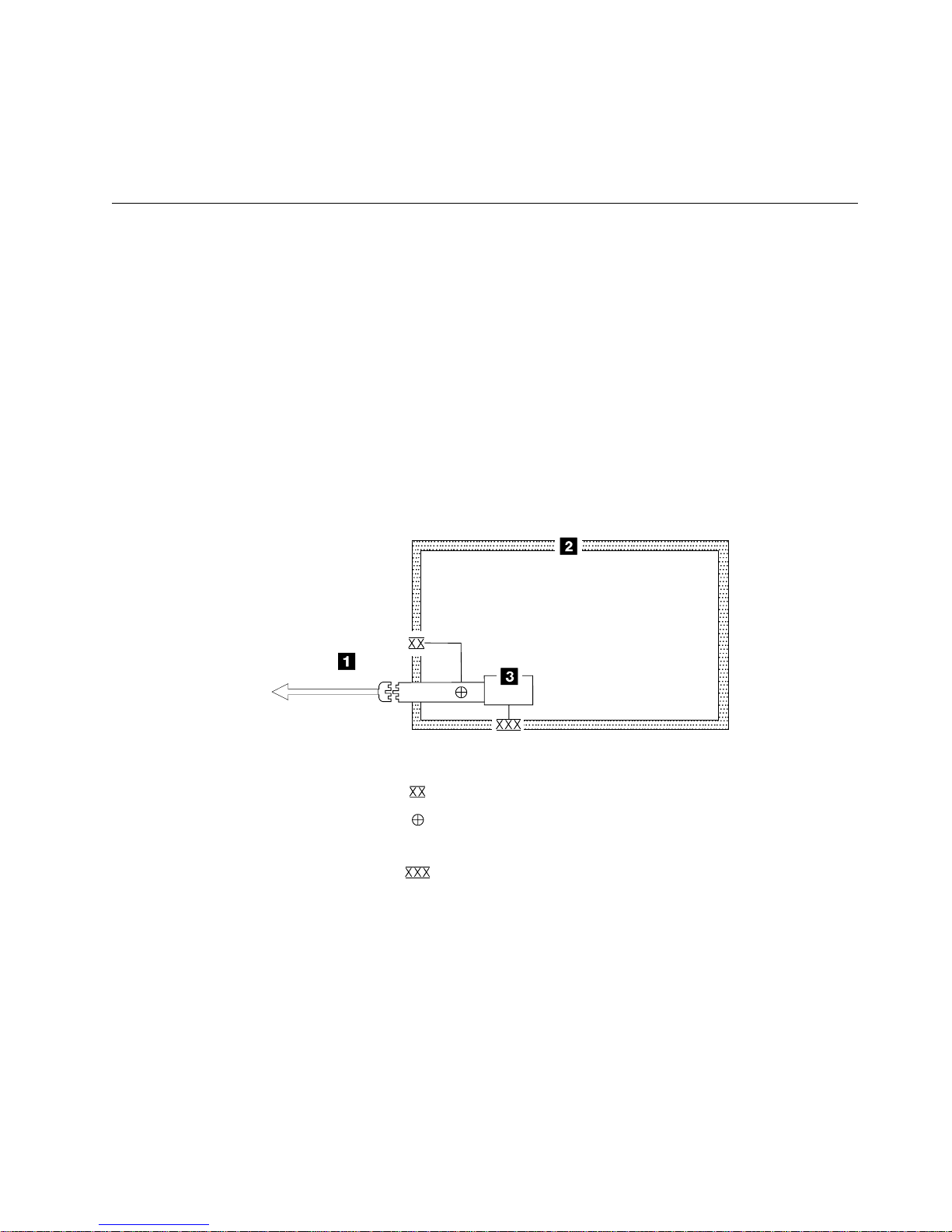
Use Figure 1 to perform the following safety procedures. Before starting the
procedures, ensure the existing room and electrical conditions are safe.
XXX
Legend:
External tooth lock washer
Green/yellow ground wire terminated to chassis or ground
Green/yellow ground wire terminated with slip-on spade terminal
Redundant ground path to frame
XXX
External tooth lock washer
Figure 1. AC Grounding Diagram (50 Hz and 60 Hz)
1. Power off the 8mm Tape Library.
2. Disconnect the channel cables.
3. Disconnect the power cord 1 from its source.
4. Check that no voltage exists between the housing on the power source and the
building ground.
5. Verify that resistance is less than 0.1 ohm from the building ground to the
power supply enclosure 3 .
6. Inspect the power cable 1 for visible cracks, wear, or damage.
A34M0139
Notices ix
Page 12

7. Check that resistance between the power cable ground and the 8mm Tape
Library frame 2 is less than 0.1 ohm.
8. Inspect the power supply enclosure covers 3 to ensure that all screws are
installed and are tight.
Environmental Notices
The following is environmental information pertaining to the 8mm Tape Library.
Product Recycling
This unit contains recyclable materials. The materials should be recycled where
facilities are available and according to local regulations. In some areas, IBM will
provide a product take-back program that ensures proper handling of the product.
Contact your IBM representative for more information.
Product Disposal
This unit may contain batteries. The batteries must be removed and discarded, or
recycled according to local regulations and where facilities exist. Specific
information per battery type will be referenced throughout the manual where
applicable.
Environmental Design
The environmental efforts that have gone into the design of this unit signifies IBM’s
commitment to improve the quality of its products and processes. Some of these
activities include elimination of the use of CFCs, development of reusable or
recyclable packaging, and reductions in manufacturing wastes.
Trademarks
The following terms are trademarks of the IBM Corporation in the United States or
other countries or both:
IBM
AIX
IBMLINK
RS/6000
AIX System Backup and Recovery/6000
The following terms are trademarks of other companies:
CSA Canadian Standards Association
UL Underwriter’s Laboratories
x 7331 and 3449 Installation Guide
Page 13

IBM Agreement for Licensed Internal Code
You accept the terms of this Agreement by your initial use of a machine that
contains IBM Licensed Internal Code (called “Code”).
These terms apply to Code used by certain machines IBM or your reseller specifies
(called “Specific Machines”). International Business Machines Corporation or one of
its subsidiaries (“IBM”) owns copyrights in Code or has the right to license Code.
IBM or a third party owns all copies of Code, including all copies made from them.
If you are the rightful possessor of a Specific Machine, IBM grants you a license to
use the Code (or any replacement IBM provides) on, or in conjunction with, only the
Specific Machine for which the Code is provided. IBM licenses the Code to only
one rightful possessor at a time.
Under each license, IBM authorizes you to do only the following:
1. Execute the Code to enable the Specific Machine to function according to its
Official Published Specifications (called “Specifications”);
2. Make a backup or archival copy of the Code (unless IBM makes one available
for your use), provided you reproduce the copyright notice and any other
legend of ownership on the copy. You may use the copy only to replace the
original, when necessary; and
3. Execute and display the Code as necessary to maintain the Specific Machine.
You agree to acquire any replacement for, or additional copy of, Code directly from
IBM in accordance with IBM's standard policies and practices. You also agree to
use that Code under these terms.
You may transfer possession of the Code to another party only with the transfer of
the Specific Machine. If you do so, you must 1) destroy all your copies of the Code
that were not provided by IBM, 2) either give the other party all your IBM-provided
copies of the Code or destroy them, and 3) notify the other party of these terms.
IBM licenses the other party when it accepts these terms. These terms apply to all
Code you acquire from any source.
Your license terminates when you no longer rightfully possess the Specific
Machine.
Actions You May Not Take
You agree to use the Code only as authorized above. You may not do, for
example, any of the following:
1. Otherwise copy, display, transfer, adapt, modify, or distribute the Code
(electronically or otherwise), except as IBM may authorize in the Specific
Machine's Specifications or in writing to you;
2. Reverse assemble, reverse compile, or otherwise translate the Code unless
expressly permitted by applicable law without the possibility of contractual
waiver;
3. Sublicense or assign the license for the Code; or
4. Lease the Code or any copy of it.
Notices xi
Page 14

Electronic Emission Notices
The following statement applies to this IBM product. The statement for other IBM
products intended for use with this product will appear in their accompanying
manuals.
Federal Communications Commission (FCC) Statement
Note: This equipment has been tested and found to comply with the limits for a
Class B digital device, pursuant to Part 15 of the FCC Rules. These limits are
designed to provide reasonable protection against harmful interference in a
residential installation. This equipment generates, uses, and can radiate radio
frequency energy and, if not installed and used in accordance with the instructions,
may cause harmful interference to radio communications. However, there is no
guarantee that interference will not occur in a particular installation. If this
equipment does cause harmful interference to radio or television reception, which
can be determined by turning the equipment off and on, the user is encouraged to
try to correct the interference by one or more of the following measures:
Reorient or relocate the receiving antenna.
Increase the separation between the equipment and receiver.
Connect the equipment into an outlet on a circuit different from that to which
the receiver is connected.
Consult an IBM authorized dealer or service representative for help.
Properly shielded and grounded cables and connectors must be used in order to
meet FCC emission limits. Proper cables and connectors are available from IBM
authorized dealers. IBM is not responsible for any radio or television interference
caused by using other than recommended cables and connectors or by
unauthorized changes or modifications to this equipment. Unauthorized changes or
modifications could void the user's authority to operate the equipment.
This device complies with Part 15 of the FCC Rules. Operation is subject to the
following two conditions: (1) this device may not cause harmful interference, and
(2) this device must accept any interference received, including interference that
may cause undesired operation.
Industry Canada Compliance Statement
This Class A digital apparatus meets all requirements of the Canadian
Interference-Causing Equipment Regulations.
Avis de conformité à la réglementation d'Industrie Canada
Cet appareil numérique de la classe A respecte toutes les exigences du Règlement
sur le matériel brouilleur du Canada.
European Community Compliance Statement
This product is in conformity with the protection requirements of EC Council
Directive 89/336/EEC on the approximation of the laws of the Member States
relating to electromagnetic compatibility. IBM cannot accept responsibility for any
failure to satisfy the protection requirements resulting from a non-recommended
modification of the product, including the fitting of non-IBM option cards.
xii 7331 and 3449 Installation Guide
Page 15
This product has been tested and found to comply with the limits for Class B
Information Technology Equipment according to CISPR 22 / European Standard EN
55022. The limits for Class B equipment were derived for typical residential
environments to provide reasonable protection against interference with licensed
communication devices.
Properly shielded and grounded cables and connectors (IBM part number 21H1955
or its equivalent) must be used in order to reduce the potential for causing
interference to radio and TV communications and to other electrical or electronic
equipment. Such cables and connectors are available from IBM authorized dealers.
IBM cannot accept responsibility for an interference caused by using other than
recommended cables and connectors.
Germany Only: This product is in conformity with the EN55022 class B emission
limits.
Japanese Voluntary Control Council for Interference (VCCI) Statement
Korean Government Ministry of Communication (MOC) Statement
Please note that this device has been approved for non-business purposes and
may be used in any environment including residential areas.
Notices xiii
Page 16

xiv 7331 and 3449 Installation Guide
Page 17

Preface
This publication describes the 7331–305 Stand-alone RISC System 6000 library,
the 3449–355 Stand-alone PC Server library and the 3449–356 Rack Mount PC
Server library. All 3 libraries are 8mm base tape libraries containing 20 cartridges
and up to 2 drives.
Note: Figures of the operator panels display 7331–3xx. These are for reference
Related Publications
External Devices Translated Safety Notices, SA26-7192 provides translations of
danger and caution notices.
7331 and 3449 8mm Tape Library Model 3xx Service Guide provides detailed
service information for the Tape Library.
7331 and 3449 8mm Tape Library Model 3xx Operator Guide provides
information about operating the Tape Library.
only. Panels on the actual product will display 7331–305, 3449–355, or
3449–356.
Related Webpage Sources
http://www.us.pc.ibm.com\server for information regarding the current IBM
PC Company Compatible Systems and Applications for 3449 Models 355 and
356.
About This Guide
Chapter 1, “General Information” on page 1 provides a brief overview of the
7331 8mm Tape Library.
Chapter 2, “8mm Tape Library Installation” on page 5 describes the
step-by-step instructions for proper installation of the 8mm Tape Library.
Chapter 3, “Moving the 8mm Tape Library” on page 25 describes how to pack
and move the 8mm Tape Library.
Appendix A, “Power Cables” on page 29 provides information on power cables
and their proper use.
Appendix B, “Statement of Limited Warranty” on page 33 is the 7331 and 3449
8mm Tape Library Model 3xx: Installation Guide warranty.
“Glossary” on page 37 defines terms, abbreviations, and acronyms used in this
publication.
Copyright IBM Corp. 1997 xv
Page 18

xvi 7331 and 3449 Installation Guide
Page 19
Chapter 1. General Information
This chapter provides a brief description of the 7331 and 3449 8mm Tape Libraries
and their configuration options. The options consist of 7331 Model 305, which is
used in a RISC System 6000 environment; 3449 Model 355, used in a PC Tower
environment, and; 3449 Model 356, which is used in a PC Rack Mount
environment.
ASFNLASM-00
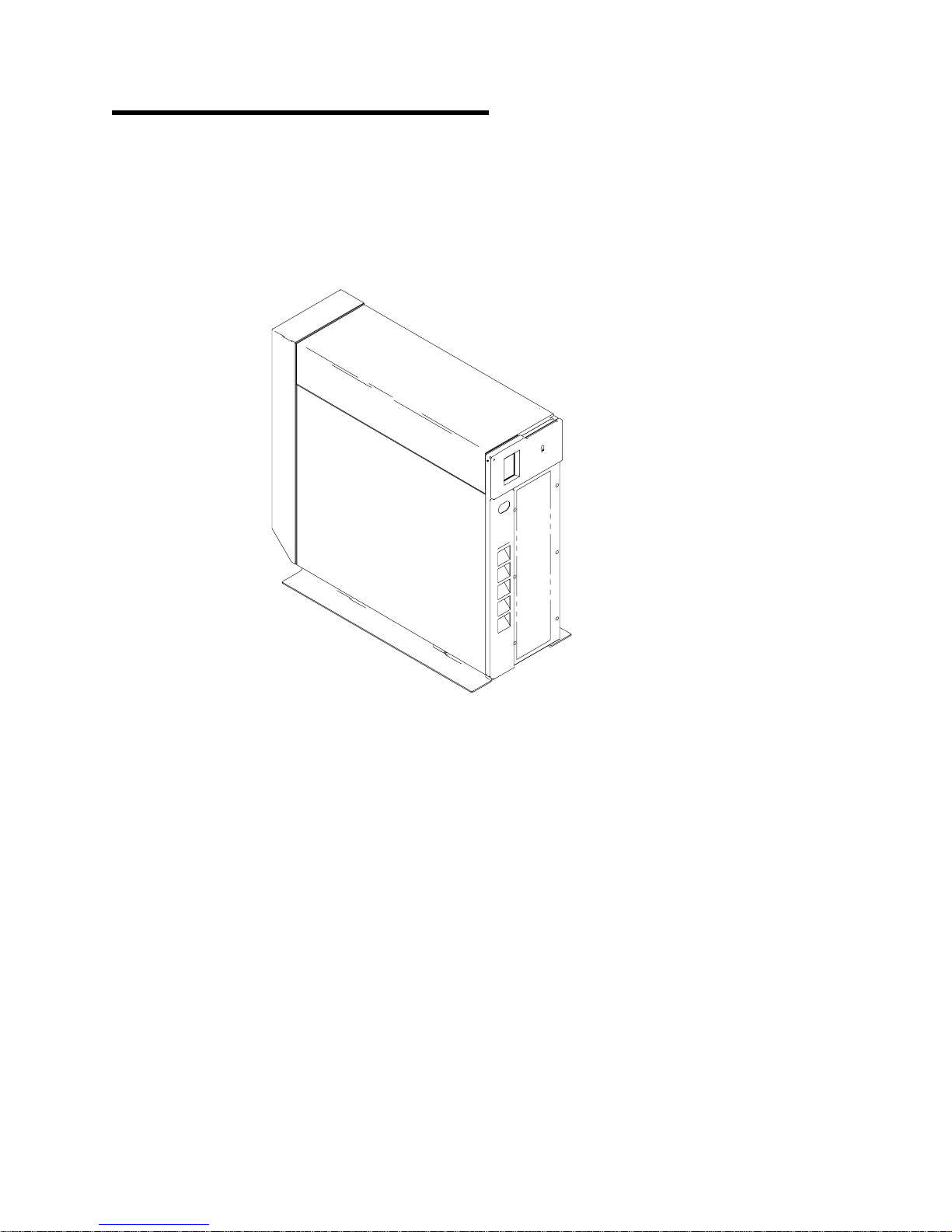
Figure 2. 8mm Tape Library
The 8mm Tape Library, provides an automated tape library solution. It can be used
as a 20-cartridge library, two 10-cartridge libraries, or as an autoloader.
The 8mm Tape Library has the following features:
The library is configured as a stand-alone tower.
An internal power supply that provides power for the tape library and the tape
drives.
One or two internally mounted tape drives.
A picker (transport mechanism) that moves tape cartridges between the
magazine slots and the tape drives.
Two removable 10-cartridge magazines, located internally above the tape
drives.
Copyright IBM Corp. 1997 1
Page 20

Two bonus slots:
– One cleaning cartridge slot.
– One custom slot for either a second cleaning cartridge, drive diagnostic
cartridge, drive test cartridge, data cartridge, or special user application
cartridges.
A front door provides access to the tape magazines and tape drives. Two locks
on the door, a key lock and a software controlled lock, provide security and
safety.
An optional bar code reader for cartridge identification.
An operator control panel with an operator key pad and a graphical liquid
crystal display (LCD).
The 8mm Tape Library provides fast wide differential Small Computer System
Interface (SCSI-2), which attaches to the RISC System/6000 (RS/6000) computer,
and IBM PC Company PC Servers.
8mm Tape Library SCSI Bus Configurations
The 8mm Tape Library can be set in the following SCSI BUS configurations:
Single host system
Dual drive - dual host system
Single Host Configuration (Single or Dual Drives)
The 8mm Tape Library is configured as a single host computer system when the
tape library is attached to a single host computer system or adapter. During
random mode, in the single host configuration, the library and all tape drives are
controlled by the single adapter. During sequential mode, in the single host
configuration, all tape drives are controlled by the single adapter.
Dual Host Configuration (Dual Drive)
A dual host configuration is used when the tape library is shared between two host
computer systems. Tape Drive 1 is controlled by the host computer system
attached to the library ports 1 and 2 (accessed using connectors 1 and 2 on the
rear of the Tape Library). Tape Drive 2 is controlled by the host computer system
attached to the library ports 3 and 4 (accessed using connectors 3 and 4 on the
rear of the Tape Library).
2 7331 and 3449 Installation Guide
Page 21

8mm Tape Library Configurations
The following configurations are supported by the tape library.
1. Base library configuration
2. Split library configuration
Base Library Configuration
In the base library configuration, the library elements are only accessible to the host
through the primary port (accessed using the connector on the rear of the library).
The second port is not enabled as a target.
Base Configuration External Cabling Requirements
The base library configuration supports the following SCSI BUS configurations.
Prior to entering the base library configuration ensure the library is cabled in one of
the following SCSI BUS configuration options:
1. Single Drive - Single Host SCSI Configuration
2. Dual Drive - Single Host SCSI Configuration
3. Dual Drive - Dual Host SCSI Configuration
Split Library Configuration
The split library configuration divides the library elements in half. The elements in
the lower magazine and Tape Drive 1 are assigned to the primary port. The
elements in the upper magazine and Tape Drive 2 are assigned to the secondary
port. The bonus slots and picker elements are shared by both ports. Elements are
only accessible through their respective ports.
Split Configuration External Cabling Requirements
The split library configuration supports the following SCSI BUS configurations. Prior
to entering the split library configuration ensure the library is cabled in one of the
following SCSI BUS configuration options:
1. Dual Drive - Single Host SCSI Configuration
2. Dual Drive - Dual Host SCSI Configuration
8mm Tape Library Modes
The 8mm Tape Library supports the following modes of operation: These modes
are selected using the library control panel.
Manual Mode (Default)
Random Mode (Selectable)
Sequential Mode (Selectable)
Random/Sequential (Available only in Split configuration)
Sequential/Random (Available only in Split configuration)
See the 7331 and 3449 8mm Tape Library Model 3xx Operator Guide, for a more
detailed description of all the modes.
Chapter 1. General Information 3
Page 22

4 7331 and 3449 Installation Guide
Page 23

Chapter 2. 8mm Tape Library Installation
This chapter provides step-by-step instructions on how to properly install the 7331
and 3449 Tape Library Model 3xx. You should complete the following steps when
installing the 8mm Tape Library.
Step 1. Checking the Electrical Outlets
DANGER
An electrical outlet that is not correctly wired could place hazardous
voltage on metal parts of the system or the products that attach to the
system. It is the customer's responsibility to ensure that the outlet is
correctly wired and grounded to prevent an electrical shock.
(RSFTD201)
Make sure the electrical outlets you use are properly grounded and meet the
following library power specifications.
Figure 3. Tape Library Power Specifications
Kv A: 0.34
Vac 100 to 127, or 200 to 240
Hertz 50 to 60
Watts 340
Step 2. Before You Begin
You will need to refer to the appropriate system manuals to locate information
required to install the Tape Library.
Get any system unit manuals that pertain to connecting peripheral equipment to
the system unit.
You may find the needed information under the following topics:
– Installing an external SCSI device
– External SCSI devices
DO NOT CONTINUE until you have located the manuals that describe how to:
Locate the SCSI controller where the 8mm Tape Library will be connected.
Determine the proper way to do a controlled shutdown and system start-up of
the system unit.
Tools required for installation:
#2 Phillips screwdriver
Copyright IBM Corp. 1997 5
Page 24

Step 3. Inventory Checklist
The following items, required to install your stand-alone Tape Library, are shipped
with the unit.
Make sure you have received the following items:
Power cables for 7331 Model 305 and 3449 Model 355 1 , and 3449 Model
356 2 power cables are represented in Figure 4 and detailed in Appendix A,
Power Cables.
Figure 4. Power Cable for Models 305 and 355 and Model 356
The 7331 and 3449 Tape Library Model 3xx Operator Guide
The 7331 and 3449 Tape Library Model 3xx Service Guide
The External Devices Translated Safety Notices
The External Devices Warranty Information (U.S., Canada, and Puerto Rico
only)
SCSI signal cables (1 or 2 depending on the configuration)
Terminators (1 or 2 depending on the configuration)
Tape cartridge magazines (2)
Data cartridge (1)
Cleaning cartridge (1)
Test cartridge (1)
Bar code labels (optional on Model 305 and standard on Models 355 and 356)
External SCSI jumper cable (shipped installed onto machine)
Device Driver (A-Tape) Diskette with License Agreement (Model 305 only)
3449 Fastwide SCSI Adapter Card (Models 355 and 356 only)
Checklist for Rack Mount Model 356
The Rack Mount assembly kit for Model 356 consists of the following hardware:
1. Rack bezel (2)
2. Filler strip (2)
3. Filler panel (1)
4. Rack plate (1)
5. Rack spacer (1)
6. Rail, LH (1)
7. Rail, RH (1)
8. M5 fastener (2)
9. M6 fastener (2)
10. M3x4 PH screw (10)
11. M4x8 PH screw (4)
6 7331 and 3449 Installation Guide
Page 25

After completing the installation of the library, store this guide, the 7331 and 3449
8mm Tape Library Model 3xx Operator Guide, the 7331 and 3449 8mm Tape
Library Model 3xx Service Guide, and External Devices Translated Safety Notices
with your host computer system documentation near the 8mm Tape Library.
Step 4. Unpacking the 8mm Tape Library
CAUTION:
The weight of this part or unit is between 32 and 55 kilograms (70.5 and 121.2
pounds). It takes three persons to safely lift this part of unit. (RSFTC205)
Attention: The 8mm Tape Library is a precision device that requires reasonable
care in handling to prevent damage to the library. Avoid bumping or dropping the
8mm Tape Library.
Perform the following steps:
Step 1. Open the library front door.
Step 2. Remove any packing material from the 8mm Tape Library.
Step 3. Loosen the picker transport lock screw, slide lock to right, and tighten lock
screw (see Figure 5).
Step 4. Install 10 cartridge magazines into the library.
Picker
Lock
Figure 5. Picker Transport Lock
Picker
ASPKLK-00
Chapter 2. 8mm Tape Library Installation 7
Page 26

Step 5. Host System Unit Setup for Connection to the 8mm Tape
Library
Is the System Unit Power On?
YES Go to “Step 5a.”
NO Go to “Step 5b.”
Step 5a.
Is the SCSI Card installed in the system unit ?
Note: A SCSI card is required for RS/6000 and PC Server attachment to the 8mm
Tape Library.
YES Go to “Step 7. Placing the 8mm Tape Library” on page 16.
NO Perform the following:
Note: The information required to do a controlled system
shutdown of the system unit can be found in the system
management or planning documentation, or obtained from
the person responsible for the management, planning,
configuration, or operation of the system.
Step 5b.
1. Do a controlled system shutdown.
2. Install the SCSI card in the system unit. See the system unit
documentation for installation of the card.
3. Power on the system unit.
4. Go to “Step 7. Placing the 8mm Tape Library” on page 16.
Is the SCSI Card installed in the system unit ?
Note: A SCSI card is required for RS/6000 and PC Server attachment to the 8mm
Tape Library.
YES Perform the following:
1. Power on the system unit.
2. Go to “Step 7. Placing the 8mm Tape Library” on page 16.
NO Perform the following:
Note: The information required to do a controlled system
shutdown of the system unit can be found in the system
management or planning documentation, or obtained from
the person responsible for the management, planning,
configuration, or operation of the system.
8 7331 and 3449 Installation Guide
Install the SCSI card in the system unit. See the system unit
documentation for installation of card.
Power on the system unit.
Go to “Step 7. Placing the 8mm Tape Library” on page 16.
Page 27

Step 6. Installing the Rack Hardware and the Rack-Mounted 8mm Tape
Library Model 356
Use the following procedure to install the Rack Hardware and the Rack-Mounted
Model 356.
Step 1. If required, vary off the rack devices where the library will be installed.
Step 2. If required, remove rack front and rear covers where the library will be
installed.
Note: These instructions are written for the installation of a single
library into a rack that does not currently have a library
installed. If a library is already installed, or if two libraries are
being installed, modify the instructions as required to
accomplish the installation.
Step 3. Position right rail alignment pin on the front of the rail in the 4th hole
from the bottom in right front rack upright. Position also, the U-shaped
channel on back of rail around nut clip in the rear upright. See
Figure 6.
Figure 6. Rail Alignment and Installation
Step 4. At the front of the rack, install a screw 1 through rack upright and
Step 5. Repeat steps 3 through 4 of this procedure to install rail on the other
Chapter 2. 8mm Tape Library Installation 9
into the threaded hole in the rail and tighten screw. See Figure 6.
side of rack.
Page 28

Step 6. Place base plate 2 on rails 1 and 3 on rack. Position plate with
large holes to front and left. Do not fasten plate to rails at this time.
See Figure 7.
Figure 7. Base Plate Installation
10 7331 and 3449 Installation Guide
Page 29
Step 7. Assemble the frame that surrounds the library front door and holds
the filler plate.
Step a. Arrange the 2 filler strips 1 and 4 , and 2 bezel strips
2 and 5 , and fasten together with 2 screws 3
(typical 2 screws each corner) at each corner. See
Figure 8.
Step b. This frame assembly is mounted on the front of the rack
and it frames the library. When installed the bezel strips
are on each side and the filler strips are at the top and
bottom.
Figure 8. Filler Strip and Bezel Strip Assembly
Chapter 2. 8mm Tape Library Installation 11
Page 30

Step 8. Position bezel and filler strip assembly 3 on rack and fasten in place
with 2 screws 1 (typical 4 places) on each side. Screws are inserted
from inside the rack through rack upright into pan nuts in bezel strips
2 . See Figure 9.
Figure 9. Filler Strip and Bezel Strip Installation
Step 9. Slide the base plate until aligned with the bezel and filler strip
assembly.
Step 10. Refer back to Figure 7 on page 10 for this procedure. At the rear of
the base plate 2 , align holes through base plate with threaded hole
in rails on each side 1 and 3 .
Step 11. Refer back to Figure 7 on page 10 for this procedure. Insert screws
4 through the holes aligned in previous step into the threaded hole
in the rail and tighten screws to secure the base plate in place.
Step 12. Obtain the library to be installed.
Step 13. Open the library front door 4 . See Figure 10 on page 13.
Step 14. Remove the cable tie securing the control panel cable 2 to the safety
cover 3 .
Step 15. Disconnect the control panel signal cable from the control panel.
DANGER
To prevent a possible electrical shock when adding or
removing any devices to or from the system, ensure that
the power cords for those devices are unplugged before
the signal cables are connected or disconnected. If
possible, disconnect all power cords from the existing
system before you add or remove a device.
12 7331 and 3449 Installation Guide
Page 31
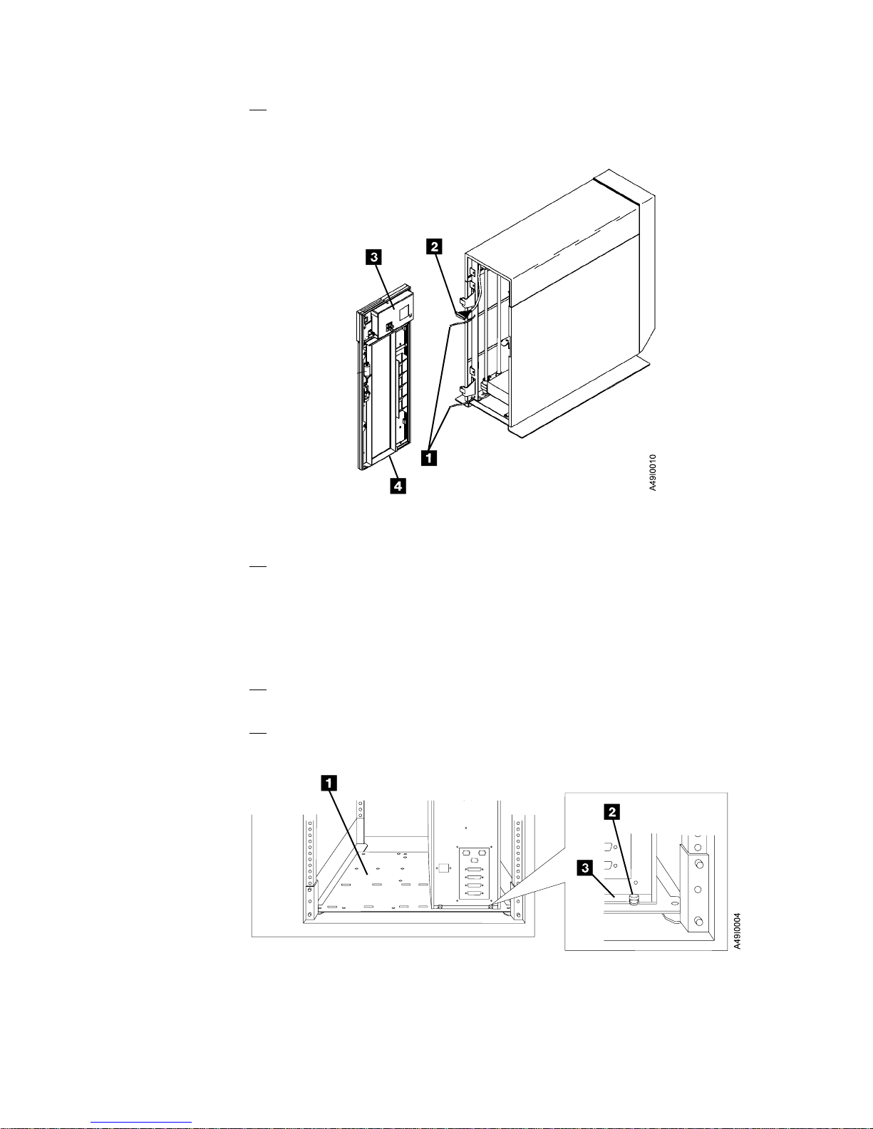
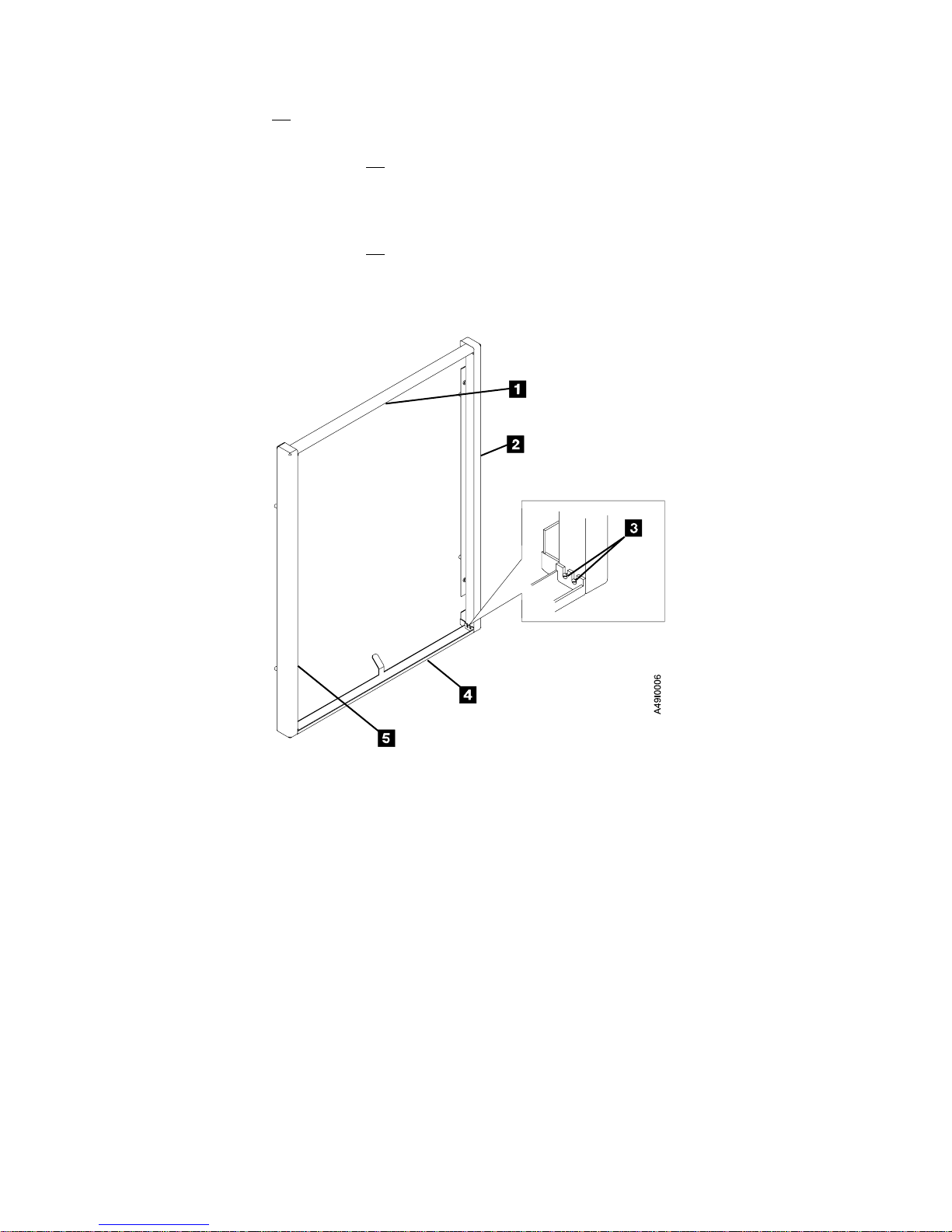
Step 16. On the inside of the front door, remove the screw securing each
frame-to-door ground strap. There are two ground straps 1 . See
Figure 10.
Figure 10. Ground Straps (Frame to Door)
Step 17. Grasp the front door assembly 4 and lift it off the hinges. Place the
front door assembly where it will not get damaged.
Note: To provide easier access to library assemblies during
maintenance in a single library configuration, it is
recommended the library be positioned on the left side of the
rack.
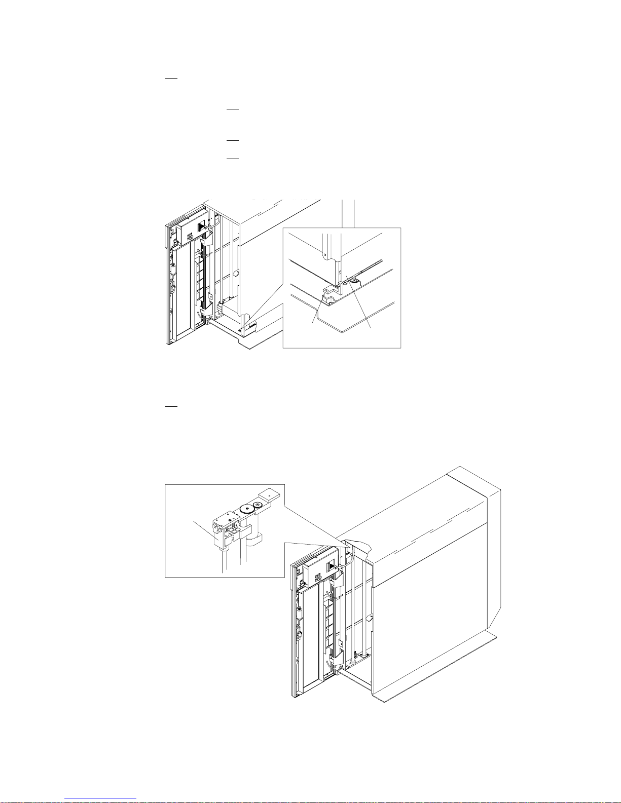
Step 18. Position the library in the rack on the left side of the rack base plate
1 . See Figure 11.
Step 19. Slide the library in position so the slots at bottom rear of library frame
3 engage screws 2 at rear of base plate. See Figure 11.
Figure 11. Library Frame Rear Alignment
Chapter 2. 8mm Tape Library Installation 13
Page 32

Step 20. Align holes in the bottom front corners of the library frame with
threaded holes in base plate and secure in position with screws 1
(typical both front covers). See Figure 12.
Figure 12. Library Front Frame Alignment
Step 21. Tighten screws at bottom rear of library frame. See Figure 11 on
page 13.
Step 22. Slide base plate with library attached to rear most position on the
rails.
Step 23. Position the filler plate 1 in bezel opening next to the library so the
tabs 2 without screw holes slip into the slot in the bezel strip at the
side of the rack and the tabs with screw holes align with the holes in
the library frame. See Figure 13.
Figure 13. Filler Plate Installation
Step 24. Using 2 screws, fasten the filler plate to the library. See Figure 13.
Step 25. Obtain the front door assembly and align the hinge pins with the
14 7331 and 3449 Installation Guide
library hinges and lower the door assembly into position.
Page 33

Step 26. Connect each frame-to-door ground strap to the inside of the front
door. See Figure 10 on page 13.
Step 27. Connect the control panel signal cable to the control panel.
Step 28. Install a cable tie to secure the control panel cable to the safety cover.
Note: The door does not lock in step 29. The library door solenoid
locks the door when library power is turned On.
Step 29. Close the library front door. Ensure the door latches and operates
correctly.
Step 30. Ensure the library, filler panel, and bezel assembly are all correctly
aligned.
Step 31. If two libraries are installed in the rack, connect the rear upper inside
corners of the library frames with an alignment strap.
Step 32. Connect the external SCSI cables between the host computer system
and the 8mm Tape Library. See “Step 8. Connecting the SCSI Signal
Cable” on page 16.
Step 33. Plug the library power cable into the rack power outlet.
Step 34. Install any rack panels that were removed fro the library installation.
Step 35. Go to “Step 13. 8mm Tape Library Checkout Procedure” on page 20.
Chapter 2. 8mm Tape Library Installation 15
Page 34

Step 7. Placing the 8mm Tape Library
The 8mm Tape Library can be located anywhere that is convenient to your system
unit. The only restrictions to the location of the library are the lengths of the power
cord and the SCSI cable.
CAUTION:
The weight of this part or unit is between 32 and 55 kilograms (70.5 and 121.2
pounds). It takes three persons to safely lift this part of unit. (RSFTC205)
Attention: The 8mm Tape Library is a precision device requiring reasonable care
in handling to prevent damage to the library. Avoid bumping or dropping the 8mm
Tape Library.
Perform the following steps:
Step 1. Place the 8mm Tape Library in the desired location.
Step 2. Remove the rear cover.
Attention: Do not place anything on top of the 8mm Tape Library.
Step 8. Connecting the SCSI Signal Cable
Note: The internal SCSI cables are installed and connected at the factory.
Determine the SCSI cable option for your system configuration and follow the
connection instructions listed with that option. Refer to “8mm Tape Library
Configurations” on page 3 for a description of possible system configurations.
–“Step 9. Single Drive – Single Host SCSI Configuration” on page 17
–“Step 10. Dual Drive – Single Host SCSI Configuration” on page 18
–“Step 11. Dual Drive – Dual Host SCSI Configuration” on page 19
DANGER
To prevent a possible electrical shock when installing the device,
ensure that the power cord for that device is unplugged before
installing signal cables. (RSFTD204)
DANGER
To prevent a possible electrical shock from touching two surfaces
with different electrical grounds, use one hand, when possible, to
connect or disconnect signal cables. (RSFTD004)
16 7331 and 3449 Installation Guide
Page 35

Step 9. Single Drive – Single Host SCSI Configuration
System Unit
System
Adapter
System-to -De vice
SCSI Cable
T
Terminator
Tape Library
Backpanel
SCSI Jumper
A
1
2
3
4
B
C
T
RSCSI01-00
Figure 14. Single Drive-Single Host SCSI Configuration
Refer to Figure 14 and perform the following steps:
Step 1. Remove 2 screws at the bottom of the back cover and lift the cover
off the library.
Step 2. Make sure the SCSI jumper cable is installed across connectors 2
and 3 on the library back panel.
Note: With the SCSI jumper cable installed, the library is configured
as a single SCSI bus. The library and tape drive respond on
this bus.
Step 3. Make sure the terminator is installed on connector 4.
Step 4. Align the external SCSI cable with connector 1 on the library back
panel.
Step 5. Push in to seat the cable and tighten the thumbscrews (finger tight).
Step 6. Connect the other end of the SCSI cable to the system unit.
Step 7. Go to “Step 12. Connecting the Power Cables” on page 20.
Chapter 2. 8mm Tape Library Installation 17
Page 36

Step 10. Dual Drive – Single Host SCSI Configuration
System Unit
System
Adapter
System-to-Device
SCSI Cable
T
Terminator
Tape Library
Backpanel
SCSI Jumper
A
1
2
3
4
B
C
T
RSCSI02-00
Figure 15. Dual Drive-Single Host SCSI Configuration
Refer to Figure 15 and perform the following steps:
Step 1. Remove 2 screws at the bottom of the back cover and lift the cover
off the library.
Step 2. Make sure the SCSI jumper cable is installed across connectors 2
and 3 on the library back panel.
Note: With the SCSI jumper cable installed, the library is configured
as a single SCSI bus. The library and both tape drives
respond on this bus.
Step 3. Make sure the terminator is installed on connector 4.
Step 4. Align the external SCSI cable with connector 1 on the library back
panel.
Step 5. Push in to seat the cable and tighten the thumbscrews (finger tight).
Step 6. Connect the other end of the SCSI cable to the system unit.
Step 7. Go to “Step 12. Connecting the Power Cables” on page 20.
The advantages of this configuration include:
Two jobs can be run simultaneously.
Library functions available for both drives (for Random Mode only).
The disadvantage of this configuration is the loss of drive performance.
18 7331 and 3449 Installation Guide
Page 37

Step 11. Dual Drive – Dual Host SCSI Configuration
System Unit
1
System
Adapter
System-to-Device
SCSI Cable
System Unit
A
1
B
C
Tape Library
Backpanel
2
System
Adapter
T
Terminator
2
3
4
T
T
RSCSI03-00
Figure 16. Dual Drive-Dual Host SCSI Configuration
Refer to Figure 16 and perform the following steps:
Step 1. Remove 2 screws at the bottom of the back cover and lift the cover
off the library.
Step 2. If a SCSI jumper cable is installed across connectors 2 and 3 on the
library back panel, remove it at this time.
Note: With the SCSI jumper cable removed, the library is configured
as two SCSI buses. The library and drive 1 are on the first bus
(ports 1 and 2) and drive 2 is on the second bus (ports 3 and
4).
Step 3. Install a terminator on connector 2 and connector 4.
Step 4. Align the external SCSI cable for system unit 1 with connector 1 on
the library back panel.
Step 5. Push in to seat the cable and tighten the thumbscrews (finger tight).
Step 6. Connect the other end of the SCSI cable to system unit 1.
Step 7. Align the external SCSI cable for system unit 2 with connector 3 on
the library back panel.
Step 8. Push in to seat the cable and tighten the thumbscrews (finger tight).
Step 9. Connect the other end of the SCSI cable to system unit 2.
Step 10. Go to “Step 12. Connecting the Power Cables” on page 20.
The advantages of this configuration include:
One 8mm Tape Library with two drives can be shared with two host systems.
Two jobs can be run simultaneously from two host systems.
Chapter 2. 8mm Tape Library Installation 19
Page 38

The disadvantage to this configuration is the reduced capacity. Only 10 tape
cartridges are available for use per host.
Step 12. Connecting the Power Cables
Perform the following steps:
Step 1. Plug the library power cable into the back of the library and into a
grounded power outlet. (This may or may not power on the library
depending upon the state of the power switch.)
Step 2. If the library power-on indicator lights and the display shows the
message, Power On Selftest in Progress, press the control panel power
switch ( ) to turn the library power Off.
Step 3. Install any library covers that are not installed.
Note: Use care when installing the rear cover after the SCSI cables
have been attached to the 8mm Tape Library.
Step 13. 8mm Tape Library Checkout Procedure
Note: The 8mm Tape Library includes internal diagnostics that can help identify
faults within the device. These diagnostics, called Power-On Self Tests
(POSTs), are run each time the 8mm Tape Library power is switched on.
This procedure should be followed the first time the library is powered on and any
other time library operation is suspect. Performing this procedure ensures that all
selftests are performed by the library and that the library initializes to a known
state.
Step 1. Ensure the library door is closed. (Required for initialization.)
Step 2. Ensure library is supplied with termination power from a SCSI host
adapter. If termination power is not provided the 8mm Tape Library will
post a 01E5 (drive presence) error.
Step 3. Open the control panel access cover and press power switch ( ) to turn
the library power On.
Display Panel
Power Switch
Power-On Indicator
Figure 17. Control Panel
20 7331 and 3449 Installation Guide
ASOP03-00
Page 39

Step 4. If the library power-on indicator lights and the display shows the
message, Power On Selftest in Progress, go to step 6 on page 21
Step 5. If the library control panel does not display information, call the 8mm
Tape Library service representative.
Step 6. Wait for Power-On Self Test (POST) to complete.
The following definitions are applicable to the library Power-On Self Test (POST):
A single 1 second beep Indicates the library Power-On Self Test (POST)
completed successfully.
Recoverable error Causes the library to beep once when the error is
encountered and to display the message, Power On
Selftest Warning and other information to further
identify the cause of the error. The library resumes
operation after 3 seconds.
Irrecoverable error The library Power-On Self Test (POST) stops and the
control panel display shows failure information to identify
the cause of the error. The library may also beep and
blink (power-on indicator) one of four sequences to
indicate a specific error. These errors are defined in the
7331 and 3449 8mm Tape Library Model 3xx Service
Guide.
Step 7. At the start of POST, the power-on indicator lights and the display shows
the message in Figure 18:
Power On Selftest in Progress.
Figure 18. Power On Selftest in Progress Display
Chapter 2. 8mm Tape Library Installation 21
Page 40

Step 8. If an irrecoverable error is detected, the library beeps and the power-on
indicator blinks to indicate a specific error occurred. The control panel
display shows the message in Figure 19:
Power On Selftest Failure and other information to further identify
the cause of the error. The message is continuously displayed and
the library ends further operation.
Figure 19. Power On Selftest Failure Display
Step 9. After checking for irrecoverable errors, POST checks for recoverable
errors. If a recoverable error is detected, the library beeps once and the
display shows the message in Figure 20:
Power On Selftest Warning and other information to further identify
the cause of the error. The message is displayed for 3 seconds
before the library resumes operation.
Figure 20. Power On Selftest Warning Display
22 7331 and 3449 Installation Guide
Page 41

Step 10. At the end of POST, the library beeps for 1 second. The control panel
display shows the message in Figure 21:
Power On Selftest Complete, 3 seconds before the library resumes
operation.
Figure 21. Power On Selftest Complete Display
Step 11. If any of the following exist, call the 8mm Tape Library service
representative.
The control panel display is blank.
The power-on indicator continuously beeps and blinks an error code.
The power-on indicator does not light.
The library does not beep.
Step 12. After POST is complete, wait for the library initialization to complete.
During the initialization operation The control panel display shows the
message in Figure 22:
INITIALIZING. With the library door locked, the picker and accessor
are initialized to a known state to permit safe movement.
Figure 22. Initializing Display
Step 13. Upon successful completion of initialization, the library returns to the
mode of operation it was in before the library was powered off.
Step 14. Make sure the library covers are installed.
Step 15. If additional language support is required, refer to the 7331 and 3449
8mm Tape Library Model 3xx Operator Guide, GA32-0376, for
instructions on how to select the required language.
Step 16. You may now power-on the system unit for the library.
Note: After completing the 8mm Tape Library installation, store its publications
with your system documentation.
Chapter 2. 8mm Tape Library Installation 23
Page 42

24 7331 and 3449 Installation Guide
Page 43

Chapter 3. Moving the 8mm Tape Library
This chapter describes how to pack and move the 8mm Tape Library Model 3xx.
Move Checklist
Attention: Damage as a result of improper handling may void your equipment
warranty. Consult your local Service Representative to obtain packing materials or
assistance in preparing your Tape Library for moving.
Please do all of the following steps when moving the stand-alone Tape Library.
Note: You may need to contact a person who is knowledgeable in system
management, planning, configuration, or operations to complete some of
these steps.
Step 1. If not already done, do a controlled shutdown of the system unit.
CAUTION:
Do not place a highly reflective surface between either the picker
assembly and the tape cartridge magazines or between the
picker assembly and the tape drives. This may cause damage to
your eyes. (RSFTC238)
Step 2. Remove any tape cartridges loaded in the tape drives.
Step 3. Power-off the library. Refer to the 7331 and 3449 8mm Tape Library
Model 3xx Operator Guide, GA32-0376, for instructions on powering
off the library.
Copyright IBM Corp. 1997 25
Page 44
Step 4. If the library is being moved a long distance (for example, to another
facility) or needs to be prepared for shipment, do the following:
Step a. Remove the removable tape cartridge magazines and
tape cartridges from the bonus slots.
Step b. Position the picker at the bottom of the library.
Step c. Loosen the picker transport lock screw, slide the lock to
the left, and tighten the screw to secure the picker in
place. See Figure 23.
Picker
Lock
Picker
ASPKLK-00
Figure 23. Picker Transport Lock
Step 5. If the library is being moved a short distance (for example, across the
room), do the following:
a. Position the picker at the top of the library and lock in place with
the accessor lock (mechanical). See Figure 24.
Accessor
Lock
Figure 24. Accessor Lock
26 7331 and 3449 Installation Guide
ASACCLK-00
Page 45

DANGER
To prevent a possible electrical shock when installing the
device, ensure that the power cord for that device is
unplugged before installing signal cables. (RSFTD204)
DANGER
To prevent a possible electrical shock from touching two
surfaces with different electrical grounds, use one hand,
when possible, to connect or disconnect signal cables.
(RSFTD004)
Step 6. Unplug the library power cable from the power outlet.
Attention: When SCSI signal cables are connected to a system unit
they have to be connected to a device. Do not leave the signal cable
connected to the system if the device for that cable has been
removed.
Step 7. Disconnect the external SCSI signal cable from the 8mm Tape Library
that you are moving.
Step 8. Disconnect the other end of the SCSI signal cable disconnected in the
previous step from the system unit.
CAUTION:
The weight of this part or unit is between 32 and 55 kilograms
(70.5 and 121.2 pounds). It takes three persons to safely lift this
part of unit. (RSFTC205)
Step 9. If the library is being moved a long distance (for example, to another
facility) or needs to be prepared for shipment, do the following:
Note: The library should be packaged in the original or new
packaging material designed for shipment of the library.
a. Prepare and package the library for shipment.
b. Move preparations are complete.
Chapter 3. Moving the 8mm Tape Library 27
Page 46

DANGER
To prevent a possible electrical shock when installing the
device, ensure that the power cord for that device is
unplugged before installing signal cables. (RSFTD204)
DANGER
To prevent a possible electrical shock when adding or
removing any devices to or from the system, ensure that
the power cords for those devices are unplugged before
the signal cables are connected or disconnected. If
possible, disconnect all power cords from the existing
system before you add or remove a device.
DANGER
To prevent a possible electrical shock from touching two
surfaces with different electrical grounds, use one hand,
when possible, to connect or disconnect signal cables.
(RSFTD004)
Step 10. If the library is being moved a short distance (for example, across the
room), carefully move the library to the new location.
Step a. Connect the external SCSI cables between the host
computer system and the 8mm Tape Library. See “Step
8. Connecting the SCSI Signal Cable” on page 16.
Step b. If required, plug the system unit power cable into a
power outlet.
Step c. Plug the library power cable into a power outlet.
Step d. Unlock the picker. Support the picker with one hand
while unlocking the accessor lock (mechanical lock) then
lower picker to bottom of library. See Figure 24 on
page 26.
Step e. Power-on the library. Refer to the 7331 8mm Tape
Library Model 3xx Operator Guide, GA32-0376, for
instructions on powering on the library.
28 7331 and 3449 Installation Guide
Page 47

Appendix A. Power Cables
To avoid electrical shock, a power cable with a grounded attachment plug is
provided. Use only properly grounded outlets.
DANGER
An electrical outlet that is not correctly wired could place hazardous
voltage on metal parts of the system or the products that attach to the
system. It is the customer's responsibility to ensure that the outlet is
correctly wired and grounded to prevent an electrical shock.
(RSFTD201)
Power cables used in the United States and Canada are listed by Underwriter’s
Laboratories (UL**) and certified by the Canadian Standards Association (CSA**).
These power cables consist of:
Electrical cables, type SVT or SJT.
Attachment plugs complying with National Electrical Manufacturers Association
(NEMA) 5-15P. That is,
“For 115 V operation use a UL Listed Cable Set consisting of a minimum 18
AWG, Type SVT or SJT three conductor cable a maximum of 15 feet in length
and a parallel blade, grounding type attachment plug rated at 15 A, 125 V.”
“For 230 V operation in the United States use a UL Listed Cable Set consisting
of a minimum 18 AWG, Type SVT or SJT three conductor cable a maximum of
15 feet in length, and a tandem blade, grounding type attachment plug rated at
15 A, 250 V.”
Appliance couplers complying with International Electrotechnical Commission
(IEC) Standard 320, Sheet C13.
Power cables used in other countries consist of:
Electrical cables, type HD21.
Attachment plugs approved by the appropriate testing organization for the
specific countries where they are used.
“For units set at 230 V (outside of U. S.): Use a Cable Set consisting of a
minimum 18 AWG cable and grounding type attachment plug rated 15 A, 250
V. The Cable Set should have the appropriate safety approvals for the country
in which the equipment will be installed and marked 'HAR'.”
Model 305 Power Cables
Figure 25 lists the power cable part number, the country where the power cable
can be used, and an index number to be matched with the receptacle illustrations
shown in Figure 26 on page 31. Please contact your local dealer if your 7331 Tape
Library power cable does not match this information.
Copyright IBM Corp. 1997 29
Page 48

Figure 25. Power Cable Information
Part Number Country Index
1838574
US/Canada
6952300
US/Canada
6952301
6 ft.
Chicago
13F9940
Australia
13F9979
France
13F9997
Denmark
14F0015
South Africa
14F0033
United
Kingdom
14F0051
Switzerland
14F0069
Italy
14F0087
Israel
6952291
Colombia
Bahamas, Barbados, Bolivia, Brazil, Canada, Costa Rica,
Dominican Republic, Ecuador, El Salvador, Guatemala,
Guyana, Haiti, Honduras, Jamaica, Japan, Netherlands
Antilles, Panama, Peru, Philippines, Taiwan, Thailand,
Tobago, Trinidad, U.S.A. (except Chicago), Venezuela
Bahamas, Barbados, Bermuda, Bolivia, Brazil, Canada,
Cayman Islands, Columbia, Costa Rica, Dominican
Republic, Ecuador, El Salvador, Guatemala, Guyana, Haiti,
Honduras, Jamaica, Japan, Korea (South), Mexico,
Netherlands Antilles, Nicaragua, Panama, Peru, Philippines,
Puerto Rico, Saudi Arabia, Suriname, Taiwan, Trinidad,
U.S.A. (except Chicago), Venezuela
Chicago, U.S.A. 2
Argentina, Australia, New Zealand 3
Abu Dhabi, Austria, Belgium, Bosnia, Botswana, Bulgaria,
Croatia, Egypt, Finland, France, Germany, Greece, Iceland,
Indonesia, Korea (South), Lebanon, Luxembourg, Macau,
Macedonia, Netherlands, Norway, Portugal, Saudi Arabia,
Serbia, Slovenia, Spain, Sudan, Sweden, Turkey
Denmark 5
Bangladesh, Burma, Pakistan, South Africa, Sri Lanka 6
Bahrain, Bermuda, Brunei, Channel Islands, Cyprus,
Ghana, Hong Kong, India, Iraq, Ireland, Jordan, Kenya,
Kuwait, Malawi, Malaysia, Nigeria, Oman, People's Republic
of China, Qatar, Sierra Leone, Singapore, Tanzania,
Uganda, United Arab Emirates (Dubai), United Kingdom,
Zambia
Liechtenstein, Switzerland 8
Chile, Ethiopia, Italy 9
Israel 10
Colombia, Paraguay, Uruguay 11
1
2
4
7
30 7331 and 3449 Installation Guide
Page 49

123
56 7 8
910 11
Figure 26. Power Receptacle Index
4
Model 355 Power Cables
Model 355 cables are the same as for Model 305.
Model 356 Power Cables
The power cables for Model 356 are PN 13F9961 and PN 34G0253.
Appendix A. Power Cables 31
Page 50

32 7331 and 3449 Installation Guide
Page 51

Appendix B. Statement of Limited Warranty
The warranties provided by IBM in this Statement of Limited Warranty apply only to
Machines you originally purchase for your use, and not for resale, from IBM or your
reseller. The term “Machine” means an IBM machine, its features, conversions,
upgrades, elements, or accessories, or any combination of them. Unless IBM
specifies otherwise, the following warranties apply only in the country where you
acquire the Machine. If you have any questions, contact IBM or your reseller.
Machine: 7331 and 3449 8mm Tape Library Model 3xx: Installation Guide
Warranty Period*: One year
*Contact your place of purchase for warranty service information.
Production Status
Each Machine is manufactured from new parts, or new and used parts. In some
cases, the Machine may not be new and may have been previously installed.
Regardless of the Machine’s production status, IBM’s warranty terms apply.
The IBM Warranty for Machines
IBM warrants that each Machine 1) is free from defects in materials and
workmanship and 2) conforms to IBM’s Official Published Specifications. The
warranty period for a Machine is a specified, fixed period commencing on its Date
of Installation. The date on your receipt is the Date of Installation, unless IBM or
your reseller informs you otherwise.
During the warranty period IBM or your reseller, if authorized by IBM, will provide
warranty service under the type of service designated for the Machine and will
manage and install engineering changes that apply to the Machine.
For IBM or your reseller to provide warranty service for a feature, conversion, or
upgrade, IBM or your reseller may require that the Machine on which it is installed
be 1) for certain Machines, the designated, serial-numbered Machine and 2) at an
engineering-change level compatible with the feature, conversion, or upgrade. Many
of these transactions involve the removal of parts and their return to IBM. You
represent that all removed parts are genuine and unaltered. A part that replaces a
removed part will assume the warranty service status of the replaced part.
If a Machine does not function as warranted during the warranty period, IBM or
your reseller will repair it or replace it with one that is at least functionally
equivalent, without charge. The replacement may not be new, but will be in good
working order. If IBM or your reseller is unable to repair or replace the Machine,
you may return it to your place of purchase and your money will be refunded.
If you transfer a Machine to another user, warranty service is available to that user
for the remainder of the warranty period. You should give your proof of purchase
and this Statement to that user. However, for Machines which have a life-time
warranty, this warranty is not transferable.
Copyright IBM Corp. 1997 33
Page 52

Warranty Service
To obtain warranty service for the Machine, you should contact your reseller or call
IBM. In the United States, call IBM at 1-800-IBM-SERV (426-7378). In Canada, call
IBM at 1-800-465-6666. You may be required to present proof of purchase.
IBM or your reseller will provide certain types of repair and exchange service, either
at your location or at IBM’s or your reseller’s service center, to restore a Machine to
good working order.
When a type of service involves the exchange of a Machine or part, the item IBM
or your reseller replaces becomes its property and the replacement becomes yours.
You represent that all removed items are genuine and unaltered. The replacement
may not be new, but will be in good working order and at least functionally
equivalent to the item replaced. The replacement assumes the warranty service
status of the replaced item. Before IBM or your reseller exchanges a Machine or
part, you agree to remove all features, parts, options, alterations, and attachments
not under warranty service. You also agree to ensure that the Machine is free of
any legal obligations or restrictions that prevent its exchange. You agree to:
1. obtain authorization from the owner to have IBM or your reseller service a
Machine that you do not own; and
2. where applicable, before service is provided —
a. follow the problem determination, problem analysis, and service request
procedures that IBM or your reseller provide,
b. secure all programs, data, and funds contained in a Machine, and
c. inform IBM or your reseller of changes in a Machine's location.
IBM is responsible for loss of, or damage to, your Machine while it is 1) in IBM’s
possession or 2) in transit in those cases where IBM is responsible for the
transportation charges.
Extent of Warranty
IBM does not warrant uninterrupted or error-free operation of a Machine.
The warranties may be voided by misuse, accident, modification, unsuitable
physical or operating environment, improper maintenance by you, removal or
alteration of Machine or parts identification labels, or failure caused by a product for
which IBM is not responsible.
OR IMPLIED, INCLUDING, BUT NOT LIMITED TO, THE IMPLIED
WARRANTIES OR CONDITIONS OF MERCHANTABILITY AND FITNESS
FOR A PARTICULAR PURPOSE. THESE WARRANTIES GIVE YOU
SPECIFIC LEGAL RIGHTS AND YOU MAY ALSO HAVE OTHER RIGHTS
WHICH VARY FROM JURISDICTION TO JURISDICTION. SOME
JURISDICTIONS DO NOT ALLOW THE EXCLUSION OR LIMITATION OF
EXPRESS OR IMPLIED WARRANTIES, SO THE ABOVE EXCLUSION OR
LIMITATION MAY NOT APPLY TO YOU. IN THAT EVENT SUCH
WARRANTIES ARE LIMITED IN DURATION TO THE WARRANTY
PERIOD. NO WARRANTIES APPLY AFTER THAT PERIOD.
34
7331 and 3449 Installation Guide
Page 53

Limitation of Liability
Circumstances may arise where, because of a default on IBM’s part or other liability
you are entitled to recover damages from IBM. In each such instance, regardless of
the basis on which you are entitled to claim damages from IBM (including
fundamental breach, negligence, misrepresentation, or other contract or tort claim),
IBM is liable only for:
1. damages for bodily injury (including death) and damage to real property and
tangible personal property; and
2. the amount of any other actual direct damages or loss, up to the greater of
U.S. $100,000 or the charges (if recurring, 12 months’ charges apply) for the
Machine that is the subject of the claim.
1) THIRD-PARTY CLAIMS AGAINST YOU FOR LOSSES OR DAMAGES
(OTHER THAN THOSE UNDER THE FIRST ITEM LISTED ABOVE); 2)
LOSS OF, OR DAMAGE TO, YOUR RECORDS OR DATA; OR 3)
SPECIAL, INCIDENTAL, OR INDIRECT DAMAGES OR FOR ANY
ECONOMIC CONSEQUENTIAL DAMAGES (INCLUDING LOST PROFITS
OR SAVINGS), EVEN IF IBM OR YOUR RESELLER IS INFORMED OF
THEIR POSSIBILITY. SOME JURISDICTIONS DO NOT ALLOW THE
EXCLUSION OR LIMITATION OF INCIDENTAL OR CONSEQUENTIAL
DAMAGES, SO THE ABOVE EXCLUSION OR LIMITATION MAY NOT
APPLY TO YOU.
International Business Machines Corporation
Armonk, New York 10504, U.S.A.
Appendix B. Statement of Limited Warranty 35
Page 54

36 7331 and 3449 Installation Guide
Page 55

Glossary
SCSI. Small computer system interface: cabling used
to interface one device to another or other devices.
PC. Personal Computer: an individual workstation
comprised of 'desk-top-type' hardware including a
monitor.
RS/6000. IBM RISC System/6000: a reduced
instruction set computer.
Copyright IBM Corp. 1997 37
Page 56

38 7331 and 3449 Installation Guide
Page 57

Index
C
configuration
base library 3
SCSI bus 2
split library 3
tape library 3
D
danger vii
E
electronic emission notices xii
F
Federal Communications Commission (FCC)
statement xii
I
installation
checkout procedure 20
dual drive, dual host 19
dual drive, single host 18
host system unit setup 8
inventory checklist 6
library, unpacking the 7
placing the library 16
power cables, connecting 20
power specification 5
rack hardware 9
rack mount model 356 9
rack mount model 356, checklist 6
SCSI 16
single drive, single host 17
P
power
cables, connecting 20
model 305 29
R
rack mount model 356
check list 6
S
safety notices vii
SCSI
configuration 2
dual drive, dual host 19
dual host, dual drive 2
signal cable 16
single drive 2, 17
single host, dual drive 2, 18
W
warranty, limited 33
L
library
modes 3
limited warranty 33
M
model 356
checklist 6
installation 9
move tape library 25
Copyright IBM Corp. 1997 39
Page 58

Page 59

Readers' Comments — We'd Like to Hear from You
7331 and 3449 8mm Tape Library
Model 3xx
Installation Guide
Publication No. GA32-0375-00
Overall, how satisfied are you with the information in this book?
Overall satisfaction
How satisfied are you that the information in this book is:
Accurate
Complete
Easy to find
Easy to understand
Well organized
Applicable to your tasks
Please tell us how we can improve this book:
Very
Satisfied Satisfied Neutral Dissatisfied
Very
Satisfied Satisfied Neutral Dissatisfied
Very
Dissatisfied
Very
Dissatisfied
Thank you for your responses. May we contact you? Yes No
When you send comments to IBM, you grant IBM a nonexclusive right to use or distribute your comments
in any way it believes appropriate without incurring any obligation to you.
Name Address
Company or Organization
Phone No.
Page 60

Readers' Comments — We'd Like to Hear from You
GA32-0375-00
IBM
Fold and Tape Please do not staple Fold and Tape
PLACE
POSTAGE
STAMP
HERE
Cut or Fold
Along Line
International Business Machine Corporation
Department 61C
9000 South Rita Road
Tucson, AZ 85741-0001 U.S.A.
Fold and Tape Please do not staple Fold and Tape
GA32-0375-00
Cut or Fold
Along Line
Page 61

Index
43
Page 62

IBM
Printed in the United States of America
on recycled paper containing 10%
recovered post-consumer fiber.
GA32- 375-
 Loading...