

Page 1

®
TM
xSeries 343
Hardware Maintenance Manual
Page 2

Second Edition (May 2002)
© COPYRIGHT INTERNATIONAL BUSINESS MACHINE S CORPO RATION, 2 002. All right s rese rved.
Note to U.S. Government Users — Documentation related to restricted righ ts — Us e, dup lication or
disclosure is subject to restrictions set forth in GSA ADP Schedule Contract with IBM Corp.
Page 3

Contents
Safety...................................................................................................................................ix
Part I: User’s Guide.............................................................................................1
1 Introduction.....................................................................................................5
Notices and Statements Used in This Book.......................................................................... 5
Before You Begin................................................................................................................. 6
Handling Static-sensiti v e De vices......................................................................................... 6
2 Chassis Description .......................................................................................7
Physical Speci fications.........................................................................................................7
Features and Specifications ................................................................................................. 8
Environmental Spec ifi ca ti on s................................................................................................ 9
Chassis Feature Location....................................................................................................10
Front Panel.................................................................................................................10
Back Panel .................................................................................................................13
Internal Chassi s Fe atures....................................................................................................14
Riser Boards...............................................................................................................22
Power Supplies...........................................................................................................23
DC Power Subsystem.................................................................................................23
Peripheral Bay............................................................................................................25
Hard Drive Tray..........................................................................................................25
Cooling Subsystem.....................................................................................................26
Server Management Summary............................................................................................27
Server Board Management Controller.........................................................................27
3 Regulatory Specifications and Disclaimers...............................................29
Declaration of the Manufacturer or Importer................................................................29
Electronic Emission Notices........................................................................................29
4 Configuration Software and Utilities...........................................................33
Using BIOS Setup...............................................................................................................34
Recording Your Setup Settings...................................................................................34
If You Cannot Access Setup.......................................................................................34
Starting Setup.............................................................................................................34
Setup Menus..............................................................................................................35
Main Menu..................................................................................................................36
Advanced Menu..........................................................................................................37
Security Menu.............................................................................................................39
Server Menu...............................................................................................................40
Boot Menu..................................................................................................................42
Exit Menu ...................................................................................................................43
Upgrading the BIOS............................................................................................................44
Preparing for the Upgrade ..........................................................................................44
Upgrading the BIOS....................................................................................................45
Recovering the BIOS..................................................................................................46
Changing the BIOS Language....................................................................................47
iii
Page 4

Using the System Setup Util ity ............................................................................................47
What You Need to Do.................................................................................................47
Running the SSU from the CD....................................................................................47
Running the SSU Remotely via an Emergen cy Management Card.............................48
Starting the SSU.........................................................................................................48
Customizing the SSU..................................................................................................49
Launching a Task.......................................................................................................50
SEL Manager Add-in ..................................................................................................50
SDR Manager Add-in..................................................................................................51
FRU Manager Add-in..................................................................................................51
Exiting the SSU ..........................................................................................................52
FRU/SDR Load Utili ty..........................................................................................................52
When to Run the FRU/SDR Load Utility......................................................................53
What You Need to Do.................................................................................................53
How You Use the FRU/SDR Load Utility.....................................................................53
Using the Firmware Update Utility.......................................................................................56
Making a BMC Firmware Update Diskette..................................................................56
Updating the BMC Firmware.......................................................................................56
Making a FRU/SDR File U pdate Di skette....................................................................56
Updating the FRU/SDR Files......................................................................................57
Using the Adaptec SCSI Util ity............................................................................................57
Running the SCSI Utili ty.............................................................................................57
Part II: Service Technician’s Guide.................................................................59
Equipment Rack Precautions ..............................................................................................60
5 Upgrading the Hardware ..............................................................................61
Tools and Supplies Needed.................................................................................................61
Caution and Danger Statements .........................................................................................61
Replacing Power Supply Modules.......................................................................................63
Replacing Ha rd Disk Drives.................................................................................................64
Working Inside the System..................................................................................................66
Safety: Before You Remove Server Covers...............................................................66
Caution and Danger Statements .................................................................................66
Handling Static-sensiti ve Devices...............................................................................68
Removing and Installing the Top Cover......................................................................68
Internal Chassi s Layout..............................................................................................70
Removing and Installing Memory................................................................................71
Removing and Installing Processo rs...........................................................................72
Replacing 3.3 Volt and 5 Volt PCI Add-in Cards.........................................................78
Replacing the Ba ck Up Battery...................................................................................79
6 Upgrading the Chassis.................................................................................83
Replacing the Se rver Board........................................................................................83
Replacing the CD-ROM and Floppy Di sk Drives.........................................................85
Replacing the Front Panel Board................................................................................87
Replacing Fa n s...........................................................................................................88
Removing the Po wer Supply Cag e.............................................................................90
iv xSeries 343 Hardware Maintenance Manual
Page 5

7 Technical Reference.....................................................................................91
Connector Pinouts...............................................................................................................91
Alarms 91
DC Power Input for DC-Input Power Supply Cage......................................................92
Serial Ports.................................................................................................................93
Configuration Jumpers........................................................................................................94
System Recovery and Update Jumpers (J1E1) ..........................................................95
DSR/DCD Configuration Jumper (J6A2).....................................................................95
FRU List..............................................................................................................................96
A POST Error Codes, Messages and FRU to Failure Information ...............98
POST Codes and Error Messages............................................................................103
POST Error Beep Codes ..........................................................................................106
PC Doctor Symtom to FRU.......................................................................................108
B Equipment Log and Configuration Worksheet ........................................110
Equipment Log..................................................................................................................110
C Solving Problems........................................................................................112
Resetting the System........................................................................................................112
Initial System Startup.........................................................................................................112
Initial System Startup Checklist.................................................................................112
Running New Application So ftware....................................................................................113
Running New Application Softw are Checklist............................................................113
After the System Has Been Running Correctly..................................................................113
After the System Has Be en Runni ng Correctly Checklist..........................................113
More Problem Solving Procedures....................................................................................114
Preparing the System for Diagnostic Testing............................................................114
Monitoring POST......................................................................................................114
Verifying Proper Operation of Key System Lights.....................................................114
Confirming Loading of the Operating System............................................................114
Specific Prob lems and Corrective Actions.........................................................................115
Power Light Does Not Light......................................................................................115
No Characters Appear on Screen.............................................................................115
Characters Are Distorted or Incorrect........................................................................116
System Coolin g Fa n s Do Not Rotate Prop erly..........................................................116
Diskette Drive Activity Light Does Not Light..............................................................116
Hard Disk Drive Activity Light Does Not Light...........................................................116
CD-ROM Drive Activity Light Does Not Light............................................................117
Cannot Connect to a Server .....................................................................................117
Problems with Network.............................................................................................117
PCI Installa tion Tips..................................................................................................118
Problems with Ap plication So ftware...................................................................................118
Bootable CD-ROM Is Not Detected...................................................................................118
Problem Dete rmination Tips..............................................................................................119
D Getting Information, Help, and Services...................................................120
Getting Information............................................................................................................120
Getting Help an d Service..........................................................................................120
Contents v
Page 6

E Safety Addendum .......................................................................................124
Related Servic e Information..............................................................................................124
Safety Information.............................................................................................................124
General Safety..........................................................................................................124
Electrical Sa fety........................................................................................................125
Safety Inspection Guide............................................................................................127
Handling Electrostatic Discharge-sensitive Devices..................................................128
Grounding Requirements..........................................................................................129
Safety Notices (mul ti-lingual translations).................................................................129
F Product Notices ..........................................................................................168
Notices..............................................................................................................................168
Trademarks..............................................................................................................169
Important Notes........................................................................................................169
Index..................................................................................................................170
Figures
1. xSeries 343 Server Chassis......................................................................................... 7
2. Front Panel................................................................................................................. 10
3. Front View wi th Be ze l Removed.................................................................................12
4. Back Panel .................................................................................................................13
5. Server Board Connector and Component Locations...................................................14
6. 5 Volt Riser Boa rd......................................................................................................22
7. 3.3 Volt Riser Bo ard....................................................................................................22
8. Non-redundant DC-Power Supply Subsystem (Filler Module shown at Left)...............23
9. Fan Array with Fo u r System Fans Instal led ................................................................26
10. Tools and Supplies Needed........................................................................................61
11. Unlocking and Removing the Power Supply Modules.................................................63
12. Disconnecting the Hard Disk Drive Bay Cabl es..........................................................64
13. Removing a Hard Disk Drive.......................................................................................65
14. Removing the Top Cover............................................................................................69
15. Internal Chassis Layout..............................................................................................70
16. Installing DIMM s.........................................................................................................71
17. Raising the Locking Bar and Removing the Terminator..............................................73
18. Inserting the Processor and Lowering the Locking Bar...............................................74
19. Aligning the Heatsi n k and Installing the Heatsink Retai n ing Clip.................................75
20. Unlatching the Hea tsink Retainin g Clip.......................................................................76
21. Raising the Locking Bar on the Processor Socket ......................................................76
22. Installing a Terminator................................................................................................77
23. Replacing 3.3 Vol t or 5 Volt PCI Add -in Cards............................................................78
24. PCI Adapter Cable Installation....................................................................................79
25. Replacing the Backup Battery.....................................................................................81
26. Removing the Ser v e r Board Cabling...........................................................................83
27. Removing the Server Board Retaining Screws...........................................................84
28. Removing the Perip h eral Bay from the Ch assis..........................................................85
29. Separating the CD-ROM and Floppy Disk Drives from the Peripheral Bay .................86
30. Front Panel Removal..................................................................................................87
31. Replacing 80 mm Fans...............................................................................................88
vi xSeries 343 Hardware Maintenance Manual
Page 7

32. Replacing 40 mm Fans...............................................................................................89
33. Removing the Powe r Supply Cage.............................................................................90
34. 15-pin Alarms Connector............................................................................................91
35. DC Power Input Connector.........................................................................................92
36. DC Power Terminal Lug .............................................................................................92
37. Serial Ports A and B...................................................................................................93
38. Jumper Locations (J1E1 and J6A2) ............................................................................94
39. J6A2 Jumper Block Configured for DCD Signal..........................................................95
40. J6A2 Jumper Block Configured for DSR Signal (D e fault)............................................95
Tables
1. Server Physical Sp e c ifications..................................................................................... 7
2. Features and Specifications......................................................................................... 8
3. Environmental Speci fi cat i ons Summary....................................................................... 9
4. Front Panel Features..................................................................................................11
5. Back Panel Features..................................................................................................13
6. Rear COM2 Port Adapter Pin-out ...............................................................................18
7. Software Security Features.........................................................................................20
8. LED Indicators............................................................................................................24
9. DC Input Rating ..........................................................................................................25
10. 350 W Load Ratings...................................................................................................25
11. Configuration U tilities..................................................................................................33
12. Alarms Connector Pinout............................................................................................91
13. Serial Port Connector Pinout......................................................................................93
14. System Recovery and Update Jumper Options..........................................................95
15. Port-80h Code Definition............................................................................................98
16. Boot Block POST Codes ............................................................................................98
17. POST Code - Port 80h Codes ....................................................................................99
18. POST Codes and Error Messages............................................................................103
19. Extended POST Error Messages and Codes............................................................104
20. BMC Generated POST Beep Codes.........................................................................106
21. BIOS Generated POST Error Beep Codes...............................................................106
22. POST Memory Error 3-Beep Codes .........................................................................107
23. Diagnostic Related Syndromes.................................................................................108
Contents vii
Page 8

viii xSeries 343 Hardware Maintenance Manual
Page 9
Safety
Before instal ling this prod u c t, read the Safety Information .
Antes de instalar este produto, leia as Informações de Segurança.
Pred instalací tohoto produktu si prectete prírucku bezpecnostních instrukcí.
Læs sikkerhedsforskrifterne, før du installerer dette produkt.
Lees voordat u dit product installeert eerst de veiligheidsvoorschriften.
Ennen kuin asennat tämän tuotteen, lue turvaohjeet kohdasta Safety Information.
Avant d'installer ce produit, lisez les consignes de sécurité.
Vor der Installation dieses Produkts die Sicherheitshinweise lesen.
Prima di installare questo p rodotto, leggere le Informazion i sul la Sic urezza.
Les sikkerhetsinformas jonen (Safety Information) før du installerer dette produktet.
Antes de instalar este produto, leia as Informações sobre Segurança.
Antes de instalar este producto, lea la información de seguridad.
Läs säkerhetsinformationen innan du installerar den här produkten.
Contents ix
Page 10
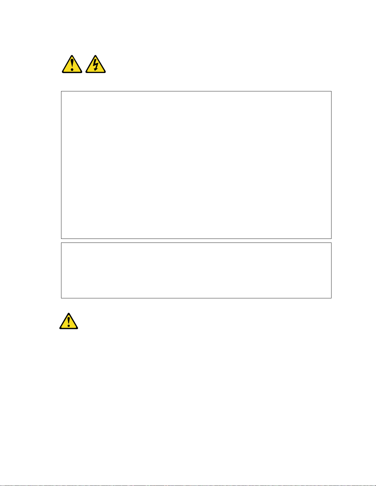
Statement 1
DANGER
Electrical current from power, telephone, and communication cables is hazardous.
To avoid a shock hazard:
- Do not connect or disconnect any cables or perform installation, maintenance, or
reconfiguration of this product during an electrical storm.
- Connect all power cords to a properly wired and grounded electrical outlet.
- Connect to properly wired outlets any equipment that will be attached to this product.
- When possible, use one hand only to connect or disconnect signal cables.
- Never turn on any equipment when there is evidence of fire, water, or structural
damage.
- Disconnect the attached power cords, telecommunications systems, networks, and
modems before you open the device covers, unless instructed otherwise in t he
installation and configuration procedures.
- Connect and disconnect cables as described in the following table when installing,
moving, or opening covers on this product or attached devices.
To Connect: To Disconnect:
1. Turn everything OFF.
2. First, attach all cables t o devices.
3. Attach signal cables to connectors.
4. Attach power cords to outlet.
1. Turn everything OFF.
2. First, remove power cords from outlet.
3. Remove signal cables from connectors.
4. Remove all cables from devices.
5. Turn device ON.
Statement 2
CAUTION
When replacing the lithium battery, use only IBM Part Number 33F8354 or an equivalent
type battery recommended by the manufacturer. If your system has a module containing a
lithium battery, replace it only with the same module type made by the same manufacturer.
The battery contains lithium and can explode if not properly used, handled, or disposed of.
Do not:
- Throw or immerse into water
- Heat to more than 100 °C (212 °F)
- Repair or disassemble
Dispose of the battery as required by local ordinances or regulations.
x xSeries 343 Hardware Maintenance Manual
Page 11
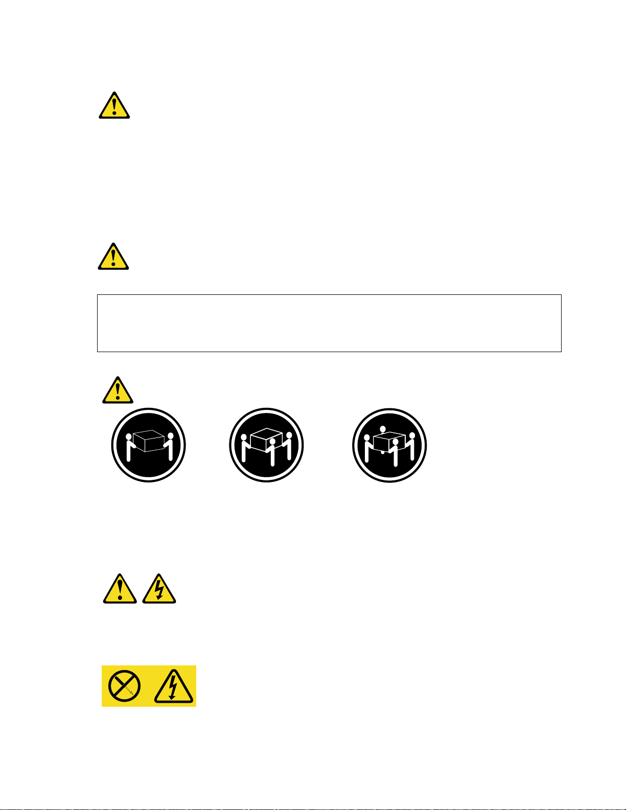
Statement 3
CAUTION
When laser products (such as CD-ROMs, DVD drives, fiber optic devices, or transmitters) are
installed, note the following:
- Do not remove the covers. Removing the covers of the laser product could result in exposure
to hazardous laser radiation. There are no serviceable parts inside the device.
- Use of controls or adjustments or performance of procedures other than those specified
herein might result in hazardous radiation exposure.
DANGER
Some laser products contain an embedded Class 3A or Class 3B laser diode. Note the following.
Laser radiation when open. Do not stare into the beam, do not view directly with optical
instruments, and avoid direct exposure to the beam.
Statement 4
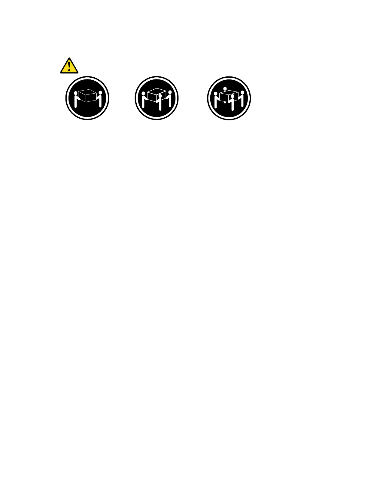
≥≥≥≥18 kg (39.7 lb) ≥≥≥≥32 kg (70.5 lb) ≥≥≥≥55 kg (121.2 lb)
CAUTION
Use safe practices when lifting.
Statement 14
CAUTION
Hazardous voltage, current, and energy levels might be present. Only a qualified service
technician is authorized to remove the covers where the following label is attached.
Contents xi
Page 12

Statement 15
CAUTION
Make sure that the rack is secured properly to avoid tipping when the server unit is
extended.
xii xSeries 343 Hardware Maintenance Manual
Page 13
Part I: User’s Guide
1 Introduction 2 Chassis Description 3 Regulatory Specifications and Disclaimers 4 Configuration Software and Utilities
This document provides an overview of the IBM
consists of two parts:
• User’s Guide, beginning on page 1 describes procedures that DO NOT REQUIRE removing
and replacing boards. You do not need to be a qualified service technician to perform
procedures listed in the User’s Guide.
• Service Technician’s Guide, beginning on page 59 describes procedures that REQUIRE
removing and replacing boards. You must be a qualified service technician to perform
procedures listed in the Service Technician’s Guide.
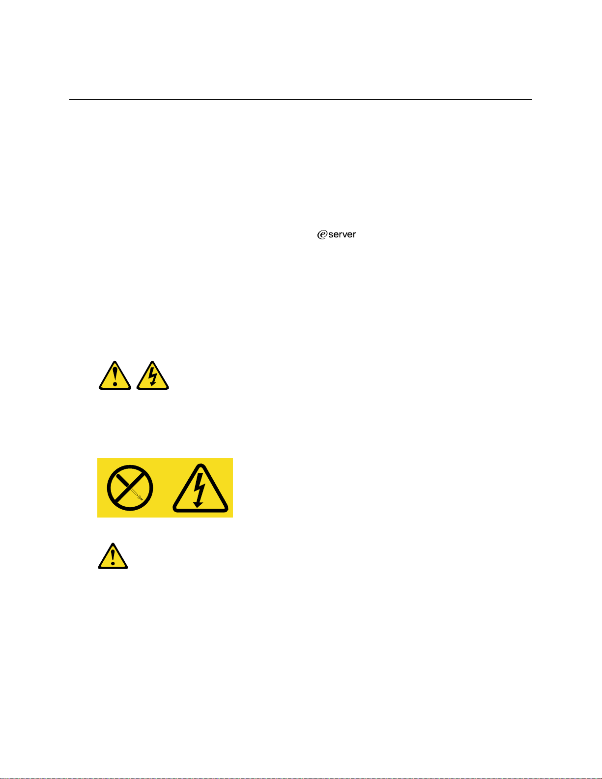
Statement 14
®
xSeries 343 server. This manual
CAUTION
Hazardous voltage, current, and energy levels might be present. Only a qualified service
technician is authorized to remove the covers where the following label is attached.
Statement 15
CAUTION
Make sure that the rack is secured properly to avoid tipping when the server unit is
extended.
1
Page 14

Notes
Only use a screwdriver tip to push in the lock tabs on the rack slides. A
pinch hazard exists if figners are used for this purpose.
DC Power supplies are installed: The DC source must be electrically
isolated by double or reinforced insulation from any hazardous DC source.
The DC source must be capable of providing up to 350 W of continuous
power per feed pair. Connection with a DC source should only be performed
by trained service personnel.
Mains DC power disconnect: You are responsible for installing a
DC power disconnect for the entire rack unit. This mains disconnect must be
readily accessible, and it must be labeled as controlling power to the entire
unit, not just to the servers(s).
Grounding the rack installation: To avoid the potential for an electrical
shock hazard, you must i nclude a third wire safety ground conductor with the
rack installation. The safety grounding conductor must be a minimum
14AWG connected to the earth ground stud on the rear of the server. The
safety ground conductor should be connected to the chassis stud with a two
hole crimp terminal with a maximum width of 0.25 inch. The nuts on the
chassis studs should be installed with a 10 in/lbs torque. The safety ground
conductor provides proper grounding only for the server. You must provide
additional, proper grounding for the rack and other devices installed in it.
Overcurrent protection: Overcurrent protection circuit breakers must be
provided as part of each host equipment rack and must be installed between
theDCsourceandtheserver. TheserverisdesignedforaDClinevoltage
power source with up to 10 amperes of overcurrent protection per feed pair.
If the DC power system for the equipment rack is installed with more than
10 amperes of protection, you must provide supplemental protection for the
server. The overall current rating of a server configured with two power
supplies is less than 7 amperes.
Temperature: The temperature in which the server operates when installed
in an equipment rack, must not go below 5 °C (41 °F) or rise above 40 °C
(104 °F). Extreme fluctuations in temperature can cause a variety of
problems in your server.
Ventilation: The equipment rack must provide sufficient airflow to the front
of the server to maintain proper cooling. The rack must also include
ventilation sufficient to exhaust a maximum of 1023 BTUs per hour for the
server. The rack selected and the ventilation provided must be suitable to the
environment in which the server will be used.
2 xSeries 343 Hardware Maintenance Manual
Page 15
Statement 4
≥≥≥≥18 kg (39.7 lb) ≥≥≥≥32 kg (70.5 lb) ≥≥≥≥55 kg (121.2 lb)
CAUTION
Use safe practices when lifting.
User’s Guide 3
Page 16

4 xSeries 343 Hardware Maintenance Manual
Page 17

1 Introduction
Thank you for purchasing an xSeries 343 server.
Your xSeries 343 server comes with a one-year limited warranty. If you have access to t he World
Wide Web, you can obtain up-to-date information about your xSeries 343 model and other IBM
server products at http://www.ibm.com/eserver/xseries.
Record your product information in this table.
Product name
Type
Model number
Serial number
This server serial number is located on labels on the rear of the server and on the front of the server
on the bezel.
______________________________________
______________________________________
______________________________________
______________________________________
Notices and Statements Used in This Book
The Caution and Danger statements also appear in the multilingual safety information book
provided on the Documentation and Resource CD. Each statement is numbered for easy reference
to the corresponding statement in the safety book.
Descriptions of the notices and statements that appear in this book are as follows:
• Notes: These notices provide important tips, guidance, or advice.
• Attention: These notices indicate possible damage to programs, devices, or data. An attention
notice is placed just before the instruction or situation in which damage could occur.
• Caution: These statements indicate situations that can be potentially hazardous to you. A
caution statement is placed just before the description of potentially hazardous procedure step
or situation.
• Danger: These statements indicate situations that can be potentially lethal or extremely
hazardous to you. A danger statement is placed just before the description of a potentially
lethal or extremely hazardous procedure step or situation.
5
Page 18

Before You Begin
Before you begin to install options in your server, read the f ollowing information:
• Become familiar with the information provided in “Handling Static-sensitive Devices” and in
the “Safety Addendum”. These guidelines will help you make changes t o disk drives.
• Make sure that you have an adequate number of properly grounded electrical outlets for your
server, monitor, and any other options that you intend to install.
• Back up all important data before you make changes to disk drives.
• For a list of supported options for the xSeries 343, refer to http://www.ibm.com/pc/compat on
the World Wide Web.
Handling Static-sensitive Devices
Attention: Static electricity can damage electronic devices and your system. To avoid damage,
keep static-sensitive devices in their static-protective package until you are ready to install them.
To reduce the possibility of electrostatic discharge, observe the following precautions:
• Limit your movement. Movement can cause static electricity to build up around you.
• Handle the device carefully, holding it by its edges or its frame.
• Do not touch solder joints, pins, or exposed printed circuitry.
• Do not leave the device where others can handle and possibly damage the device.
• While the device is still in its anti-static package, touch it to an unpainted metal part of the
system unit for at least two seconds. (This drains static electricity from the package and from
your body.)
• Remove the device from its package and install it directly into your system unit without setting
it down. If it is necessary to set the device down, place it in its static-protective package. Do
not place the device on your system unit cover or on a metal table.
• Take additional care when handling devices during cold weather because heating reduces
indoor humidity and increases static electricity.
6 xSeries 343 Hardware Maintenance Manual
Page 19
2 Chassis Descr iption
The xSeries 343 is a rack-mounted server that supports one to two Intel®Pentium®III processors
and up to 6 GB of SDRAM memory. The server supports high availability features such as
hot-swap and redundant power supply modules. The scalable architecture of the server supports
symmetric multiprocessing(SMP) and a variety of operating systems.
Physical Specifications
Table 1 lists the server’s physical specifications while Figure 1 presents a view of the xSeries
343 server chassis.
Table 1. Server Physical Specifications
Specification Value
Height 3.5 inches (89 mm)
Width 17.5 inches (445 mm)
Depth 20 inches (508 mm)
Front clearance 2 inches (76 mm)
Side clearance 1 inche (25 mm)
Rear clearance 3.6 inches (92 mm)
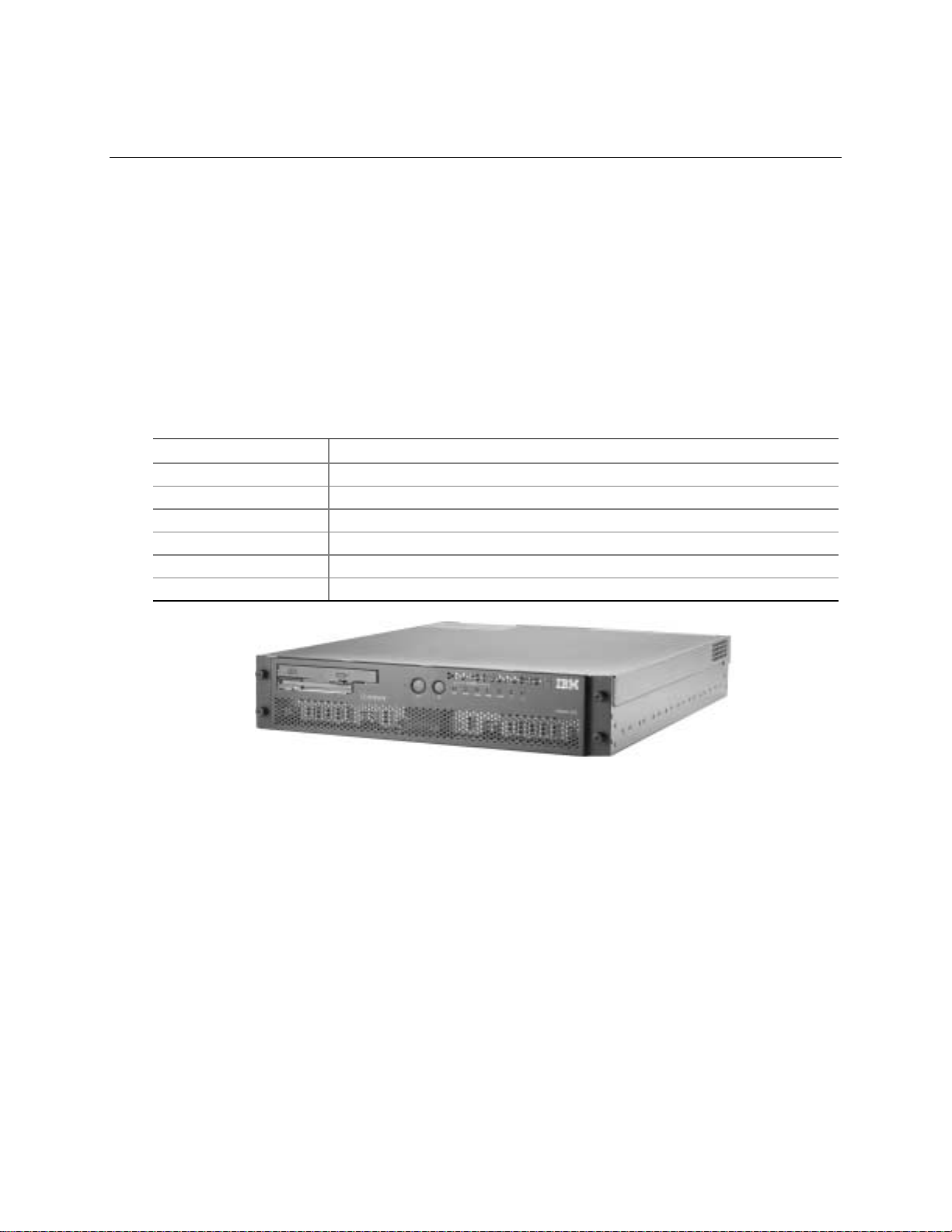
Figure 1. xSeries 343 Server Chassis
OM14189
7
Page 20

Features and Specifications
Table 2. Features and Specifications
Feature Description
Configuration 1-2 way capability in low profile and cost/val ue ef fec tiv e pac kaging
Stand-alone system
Processor Support Intel Pentium III up to 2 GHz
Power Two hot-swap 350 W power supplies in a redundant (1+1) config uration
System Management Remote management
Emergency management port (Serial and LAN)
IPMI 1.5 compliant
WfM 2.0 compliant
Remote diagnostics support
Upgrades Supports Pentium III processor family
Upgradeable to next generation Pentium IV processor family
Multi-generational chassis
Expansion 6 GB 133 MHz SDRAM memory support
Dual Intel Pentium III processor support
3 Full Height Full Length 64-bit x 66 MHz PCI Slots or; 3 Full Height Full Length
64-bit x 33 MHz PCI Slots
3 Low Profile / Half Length 64-bit x 66 MHz PCI Slots
2 internal SCSI disk drives
1 Low Profile CD-ROM
1 Low Profile floppy drive
Front panel controls and
indicators
Power switch
Reset switch
Main power LED
HDD activity LED
NIC activity LED
Telco power alarm fault LED/Relay
Telco critical alarm fault LED/Relay
Telco major alarm fault LED/Relay
Telco minor alarm fault LED/Relay
8 xSeries 343 Hardware Maintenance Manual
Page 21

Environmental Specifications
The xSeries 343 system has been tested to the environmental specifications as indicated in Table 3.
All testing has been performed per procedures defined in Bellcore GR-63-CORE NEBS Physical
Protection, Bellcore GR-3580 NEBS Criteria Levels, Bellcore GR-1089-CORE EMC and Electrical
Safety – Generic Criteria for Network Telecommunications Equipment, and the
Environmental Standards Handbook.
Intel
Table 3. Environmental Specifications Summary
Environment Specification
Temperature operating
Temperature non-operating
Altitude 0 to 1,800 m (0 to 5,905 ft)
Humidity non-operating
Vibration operating Swept sine survey at an acceleratio n ampl itud e of 0.1 g from 5 to 100 Hz
Vibration non-operating Swept sine survey at an acceleration amplitud e of 0.5 g from 5 to 50 Hz at a
Shock operating Half-sine 2 G, 11 ms pulse, 100 pulses in each direction, on each of the
Shock non-operating Trapezoidal, 25 G, 170-inch/sec delta V, three drops in each direction, on
Electrostatic discharge
(ESD)
Acoustic
5 °C to 40 °C (41 °F to 104 °F)
-40 °C to 70 °C (-104 °F to 158 °F)
95%, non-condensing at temperatures of 23 °C (73 °F) to 40 °C (104 °F)
and back to 5 Hz at a rate of 0.1 octave/minute, 90 minutes per axis on all
three axes as per Bellcore GR-63-CORE standards.
rate of 0.1 octaves/minute, and an acceleration amplitude of 3.0g from 50 to
500 Hz at a rate of 0.25 octaves/minute, on all three axes as per Bellcore
GR-63-CORE standard.
2.2 Grms, 10 minutes per axis on all three axes as per the Intel
Environmental Standards Handbook.
three axes as per the Intel Environmental Standards Handbook.
each of the three axes as per Intel Environmental Standards Handbook.
Tested to ESD levels up to 15 kilovolts (kV) air discharge and up to
8 kV contact discharge without physical damage as per Intel Environmental
Standards Handbook.
Sound pressure: < 55 dBA at ambient temperatures < 28 °C measured at
bystander positions in operating mode.
Sound power: < 6.5 dBA at ambient temperatures < 28 °C in
operating mode.
Chassis Description 9
Page 22
Chassis Feature Location
Front Panel
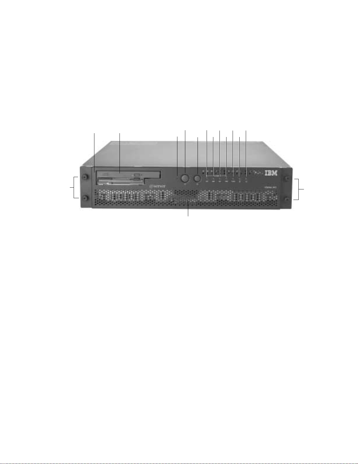
Figure 2 shows the front view of the system including the front panel. The front panel contains
system control switches, alarm indicators and relays, and status indicators. Front panel controls and
LEDs are summarized in Table 3.
M
A B
A Bezel H Alarm: MNR
B Peripheral Bay I Alarm: PWR
C NMI Switch J Status: NIC
D Power Switch K Status: DSK
E Reset Switch L Status: ON
F Alarm: CRT M Bezel Removal Thumbscrews
G Alarm: MJR N Hard Drive Tray
Figure 2. Front Panel
DF
C
E
N
HIJL
G
K
M
OM14188
10 xSeries 343 Hardware Maintenance Manual
Page 23

Table 4. Front Panel Features
Item Feature Description
Front Panel Switches
C NMI switch A momentary contact switch used to instruct the processor to copy system
memory to the hard drive. Pressing the recessed button with a paper clip or pin
puts the server in a halt state for diagnostic purposes and all ow s you to issu e a
non•maskable interrupt. After issuing the interrup t, a memory dump can be
performed to determine the cause of the problem.
D Power switch Toggles the system power on/off.
E Reset switch Reboots and initializes the system.
Front Panel Alarm LEDs and Relays
F Critical (amber) When continuously lit, indicates the presence of a Critical System Fault. A
critical system fault is an error or event that is detected by the system with a
fatal impact to the system. In this case, the system cannot continue to operate.
An example could be the loss of a large section of memory or other corruption
that renders the system not operational. Additionally, the front panel critical
alarm relay will engage.
G Major (amber) When continuously lit, indicates the presence of a Major System Fault. A major
system fault is an error or event that is detected by the system that has
discernable impact to system operation. In this case, the system can continue
to operate but in a “degraded” fashion (reduced performance or loss of
non-fatal feature reduction). An example could be the loss of one of two
mirrored disks. Additionally, the front panel major alarm relay will engage.
H Minor (amber) When continuously lit, indicates the presence of a Minor System Fault. A minor
system fault is an error or event that is detected by the system but has little
impact to actual system operation. An example would be a correctable
ECC error. Additionally, the front panel minor alarm relay will engage.
I Power (amber) When continuously lit, indicates the presence of a Power System Fault.
Additionally, the front panel power alarm relay will engage.
Front Panel Status LEDs
J NIC activity LED
(green)
K HDD activity
LED (green)
L Main power
LED (green)
Indicates NIC activity.
Indicates any system SCSI hard drive activity.
When continuously lit, indicates the presence of DC power in the server. The
LED goes out when the power is turned off or the power source is disrupted.
When it is blinking green, it indicates that the system is in ACPI sleep mode.
Chassis Description 11
Page 24
Figure 3 shows the front view of the system with the bezel removed.
A B C
H EFG
A Floppy Drive E Left SCSI Drive Bay
B CD-ROM Drive F Hard Drive Tray Ribbon Cable Connector
C Front Panel Switches and LEDs G Hard Drive Tray Power Connector
D Hard Drive Tray H Right SCSI Drive Bay
Figure 3. Front View with Bezel Removed
D
OM12817
12 xSeries 343 Hardware Maintenance Manual
Page 25
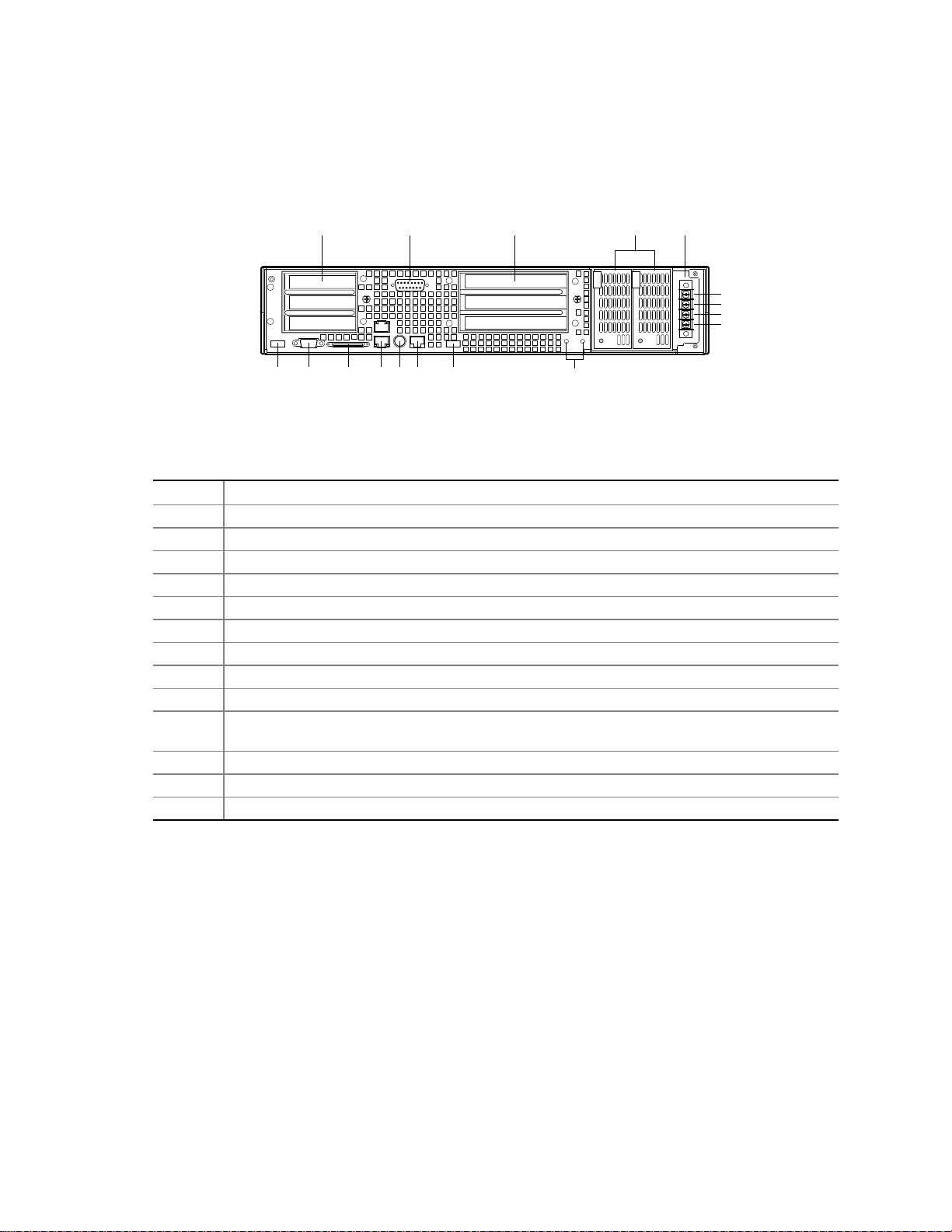
Back Panel
Figure 4 shows the back panel view of the system.
A C EB D
+
-
+
-
F G H I J K L
M
OM14192
Figure 4. Back Panel
Table 5. Back Panel Features
Item Description
A Three low profile, half-l engt h 6 4-bit, 66 MHz PCI add- in board slots (3.3 V riser board)
B DB-15 male connector for front panel alarm relay contacts
C Three full height, full length 64-bit, 33 MHz PCI add-in board slots (5 V riser board)
D Redundant, hot-plug power supplies
E Four-terminal DC input power connector for DC input power supply cage
F USB port 1
G Video connector
H External wide SCSI Ultra160 68-pin connector
I Dual NIC 10/100 E/N RJ45 connectors NIC 1 (lower) and NIC 2 (upper)
J The PS/2 port can accept both keyboard and mouse. Use the included “Y” splitter cable to
connect a mouse and a keyboard to the PS/2 port at the same time.
K Serial port (COM2), 8-pin RJ45 connector
L USB port 0
M Two grounding plugs for attachment of grounding wire to chassis
Chassis Description 13
Page 26
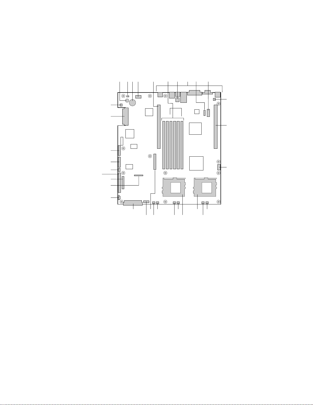
Internal Chassis Features
Figure 5 shows the location of the server board’s connectors and other components.
A C D E
B
GG
FF
EE
DD
CC
BB
AA
Z
Y
TV
UW
A
Speaker R Sys fan 2 connector
B
ID LED S CPU 1 fan connector
C
Battery T Sys fan 1 connector
D
Diagnostic LEDs (POST code) U Aux fan connector
E
66 MHz/64-bit PCI riser slot (full height) V Floppy drive connector
F
DIMM slots W Fan module connector
G
DCD/DSR jumper block X Main power connector
H
I/O ports Y Auxiliary signal connector
I
ICMB connector Z Floppy/FP/IDE connector
J
COM1 serial header AA Alternate front panel connector
K
Chassis intrusion connector BB ATA/IDE connector
L
66 MHz/64-bit PCI riser slot (low profile) CC IPMB connector
M
USB 3 & 4 header DD SSI front panel connector
N
Sys fan 3 connector EE Configuration jumper block
O
CPU 2 fan connector FF SCSI connector (SCSI version only)
P
Secondary processor socket GG Hard Disk Drive LED header
Q
Primary processor socket
H
G
R
S
JF I
K
L
M
PX N
OQ
OM12815
Figure 5. Server Board Connector and Component Locations
14 xSeries 343 Hardware Maintenance Manual
Page 27

Processor
The server board accommodates one or two Pentium III processors up to 1-26 GHz with 512k cache
in the FC-PGA2 package.
Memory
The system board contains six 168-pin DIMM slots each supporting 72-bit ECC (64-bit main
memory plus ECC) registered SDRAM DIMMs (PC-133 compatible). You may install a minimum
of 128 MB (64 MB x 2) and as much as 6 GB.
Note
Use DIMMs that have been tested for compatibility with the server board.
Contact your sales representative or dealer for a current list of approved
memory modules.
PCI Riser Slots
The server board has two PCI r iser slots: a 5 V riser that supports 64-bit/33 MHz riser cards and a
3.3 V riser that supports 64-bit/66 MHz riser cards.
• Bus speed up to 66 MHz
• 32 bit memory addressing
• 5 V/3.3 V signaling environment
• Burst transfers of up to 512 Mbps
• 8, 16, 32, or 64-bit data transfers
• Plug and Play ready
• Parity enabled
Video
The server board uses an ATI RAGE XL PCI graphics accelerator with 8 MB of video SDRAM
that supports all standard IBM VGA modes. The embedded SVGA video subsystem supports:
• Pixel resolutions up to 1600 x 1200 under 2D and 1024 x 768 under 3D
• CRT and LCD monitors up to 100 Hz vertical refresh rate
The server board supports disabling of the onboard video through the BIOS setup menu or when a
plug in video card i s installed in any of t he PCI slots.
SCSI Controller
The SCSI version of the server board includes an embedded Adaptec AIC-7899W controller
providing dual Ultra160 Low Voltage Differential (LVD) SCSI channels.
The SCSI bus is terminated on the server board with active terminators that cannot be disabled.
The onboard device must always be at one end of the bus. The device at the other end of the cable
is terminated with the active terminator on the SCSI cable installed in the system.
Chassis Description 15
Page 28

Network Controller
Note
To ensure EMC product regulation compliance for intra-building lighting
surges, the system must only be used with shielded LAN cables that are
grounded at both ends.
The server board uses two Intel 82550PM Fast Ethernet Controllers and supports two
10Base-T/100Base-TX network subsystems.
On the server board, NIC 1 can be used as both a network interface and server management
interface.
NIC Connector and Status LEDs
The 82550 controller drives LEDs on the network interface connector that indicate link/activity on
the LAN and 10- or 100-Mbps operation. The green LED indicates network connection when on
and TX/RX activity when blinking. The yellow LED indicates 100-Mbps operation when lit.
Network Teaming Features
Note
Using both on-board NICs in a team does not allow the use of NIC 1 for
server management access. To support both network teaming features and
server management features, a third NIC must be added and teamed to NIC 2.
The network controller provides several options for increasing throughput and fault tolerance when
running Linux®:
• Adapter Fault Tolerance (AFT) - provides automatic redundancy for your adapter. If the
primary adapter fails, the secondary takes over. AFT works with any hub or switch.
• Adaptive Load Balancing (ALB) - creates a team of 2 - 6 adapters t o increase transmission
throughput. Also includes AFT. Works with any 10Base-TX or 100Base-TX switch.
• Fast EtherChannel (FEC) or Intel Link Aggregation - cr eates a team of up to 6 adapters to
increase transmission and reception throughput. Also includes AFT. Requires a FEC-enabled
switch.
To set up an option, read the instructions in the Linux RH 7.1 readme files.
Adapter Fault Tolerance
Adapter Fault Tolerance (AFT) is a simple, effective, and fail-safe approach to increase the
reliability of server connections. AFT gives you the ability to set up link recovery to the server
adapter in case of a cable, port, or network interface card failure. By assigning two server adapters
as a team, AFT enables you to maintain uninterrupted network performance.
AFT is implemented with two server adapters: a primary adapter and a backup, or secondary,
adapter. During normal operation, the backup will have transmit disabled. If the link to the
primary adapter fails, the link to the backup adapter automatically takes over.
16 xSeries 343 Hardware Maintenance Manual
Page 29

Preferred Primary Adapter
With multiple adapters installed, you can specify one as the Preferred Primary adapter. For
example if you have a server with a PRO/1000 server adapter as the primary adapter and a
PRO/100+ adapter as the secondary, you could configure the PRO/1000 server adapter to be the
preferred primary. In this scenario, if the PRO/1000 server adapter fails, the PRO/100+ will take
over. Then when the PRO/1000 server adapter is r eplaced, it will automatically revert to being the
primary adapter in the team.
If a Preferred Primary is not selected, PROSet will attempt to select the best adapter, based on
adapter model and speed.
Mixed Adapter Teaming
AFT supports up to six server adapters per team, in any mix.
Adaptive Load Balancing
Adaptive Load Balancing (ALB) is a simple and efficient way t o increase your server's transmit
throughput. With ALB you group server adapters in teams to provide an increased transmit rate
(up to 8 Gbps) using a maximum of eight adapters. The ALB software continuously analyzes
transmit loading on each adapter and balances the r ate across the adapters as needed. Adapter
teams configured for ALB also provide the benefits of AFT. Receive rates remain at 100 Mbps or
1 Gbps depending on the primary adapter’s capability.
To use ALB, you must have 2-6 server adapters installed in your server or workstation and linked
to the same network switch.
Cisco Fast EtherChannel
Fast EtherChannel (FEC) is a performance technology developed by Cisco to increase your server's
throughput. Unlike ALB, FEC can be configured to increase both transmission and reception
channels between your server and switch. FEC works only with FEC-enabled switches, such as the
Catalyst 5000 series. With FEC, as you add adapters to your server, you can group them in teams
to provide up to 18 Gbps at full duplex, with a maximum of 6 server adapters. The FEC software
continuously analyzes loading on each adapter and balances network traffic across the adapters as
needed. Adapter teams configured for FEC also provide the benefits of AFT.
To use FEC, you must have 2, 4, or 6 server adapters plus use of both onboard NIC adapters
installed in your server and linked to the same FEC-enabled Cisco switch.
Keyboard and Mouse
The keyboard controller is PS/2-compatible. If specified through the System Setup Utility (SSU),
the server may be locked automatically if there is no keyboard or mouse activity for a predefined
length of time. Once the inactivity (lockout) timer has expired, the keyboard and mouse do not
respond until the previously stored password is entered. If a mouse is required, you can either
connect a USB mouse to a USB port or a PS/2 mouse to the PS/2 port using the “Y”-splitter cable.
Chassis Description 17
Page 30

RJ45 Serial Port
The rear RJ45 serial port is a fully functional COM port that supports any standard serial device
and provides support for serial concentrators, which typically support RJ45 serial connectors. For
server applications that use a serial concentrator to access the server management features of the
baseboard, a standard 8-pin CAT-5 cable from the serial concentrator is plugged directly into the
rear RJ45 serial port. The 8 pins of the RJ45 connector can be configured to match either of two
pin-out standards used by serial port concentrators. T o accommodate either standard, the
J6A2 jumper block located directly behind the rear RJ45 serial port must be jumpered appropriately
according to which standard is desired.
Note
The RJ45 serial port’s default configuration is DSR. For serial concentrators
requiring a DCD signal, configure the jumper block as shown in Figure 39.
For serial concentrators that require a DCD signal, configure the J6A2 jumper block as shown in
Figure 39.
For those server applications requiring a DB9 serial connector, use an 8-pin RJ45-to-DB9 adapter.
Table 6 defines the pin-out required for the adapter to provide RS232 support.
Table 6. Rear COM2 Port Adapter Pin-out
RJ45 Signal Abbreviation DB9
1 Request to Send RTS 7
2 Data Terminal Ready DTR 4
3 Transmitted Data TD 3
4 Signal Ground SGND 5
5 Ring Indicator RI 9
6 Received Data RD 2
7 DCD or DSR DCD/DSR 1 or 6
8 Clear To Send CTS 8
Note
The RJ45-to-DB9 adapter should match the configuration of the serial device
used. One of two pin-out configurations are used depending on whether the
serial device requires a DSR or DCD signal. The final adapter configuration
should also match the desired pin-out of the RJ45 connector, as it can also be
configured to support either DSR or DCD.
ACPI
The server board supports the Advanced Configuration and Power Interface (ACPI) as defined by
the ACPI 1.0 and PC97 specifications. An ACPI aware operating system can put the system into a
state where the hard drives spin down, the system fans stop, and all processing is halted. However,
the power supply will still be on and the processors will still be dissipating some power, so the
power supply fans will still run.
18 xSeries 343 Hardware Maintenance Manual
Page 31

The server board supports sleep states s0, s1, s4, and s5:
• s0: Normal running state.
• s1: Processor sleep state. No context will be lost in this state and the processor caches will
maintain coherency.
• s4: Hibernate or Save to Disk: The memory and machine state are saved to disk. Pressing the
power button or other wakeup event will restore the system state from the disk and resume
normal operation. This assumes that no hardware changes have been made to the system while
it was off.
• s5: Soft off: Only the RTC section of the CSB and the BMC are running in this state. No
context is saved by the OS or hardware.
Note
The system is off only when the DC power cable is disconnected.
Security
Software Locks
The BIOS Setup and the System Setup Utility (SSU) provide a number of security features to
prevent unauthorized or accidental access to the system. Once the security measures are enabled,
you can access the system only after you enter the correct password(s). For example:
• Enable the keyboard lockout timer s o that the server requires a password to reactivate the
keyboard and mouse after a specified time out period1 to 120 minutes.
• Set and enable a supervisor password.
• Set and enable a user password.
• Set secure mode to prevent keyboard or mouse input and to prevent use of the front panel reset
and power switches.
• Activate a hot key combination to enter secure mode quickly.
• Disable writing to the diskette drive when secure mode is set.
• Disable access to the boot sector of the operating system hard disk drive.
Using Passwords
You can set either the user password, the supervisor password, or both passwords.
If only the user password is set, you:
• Must enter the user password to enter BIOS Setup or the SSU.
• Must enter the user password to boot the server if Password on Boot is enabled in either the
BIOS Setup or SSU.
• Must enter the user password to exit secure mode.
If only the supervisor password is set, you:
• Must enter the supervisor password to enter BIOS Setup or the SSU.
• Must enter the supervisor password to boot the server if Password on Boot is enabled in either
the BIOS Setup or SSU.
• Must enter the supervisor password t o exit secure mode.
Chassis Description 19
Page 32

If both passwords are set, you:
• May enter the user password to enter BIOS Setup or the SSU. However, you will not be able to
change many of the options.
• Must enter the supervisor password if you want to enter BIOS Setup or the SSU and have
access to all of the options.
• May enter either password to boot the server if Password on Boot is enabled in either the BIOS
Setup or SSU.
• May enter either password to exit secure mode.
Secure Mode
Configure and enable the secure boot mode by using the SSU. When secure mode is in effect:
• You can boot the server and the operating system will run, but you must enter the user
password to use the keyboard or mouse.
• You cannot turn off system power or reset the server from the front panel switches.
• Secure mode has no effect on functions enabled via remote server management or power
control via the watchdog timer.
Taking the server out of secure mode does not change the s tate of system power. That is, if you
press and release the power switch while secure mode is in effect, the system will not be powered
off when secure mode is later removed. However, if the front panel power switch remains
depressed when secure mode is removed, the server will be powered off.
Summary of Software Security Features
Table 7 lists the software security features and describes what protection each offers. In general, to
enable or set the features listed here, you must run the SSU and go to the Security Subsystem
Group, menu. The table also refers to other SSU menus and to the Setup utility.
Table 7. Software Security Features
Feature Description
Secure mode How to enter secure mode:
Setting and enabling passwords automatically places the system in secure mode.
If you set a hot-key combination (through Setup), you can secure the system
simply by pressing the key combination. This means you do not have to wait for
the inactivity time-out period.
When the system is in secure mode:
The server can boot and run the operating system, but mouse and keyboard input
is not accepted until the user password is entered.
At boot time, if a CD is detected in the CD-ROM drive or a diskette in drive A, the
system prompts for a password. When the password is entered, the server boots
from CD or diskette and disables the secure mode.
If there is no CD in the CD-ROM drive or diskette in drive A, the server boots from
drive C and automatically goes into secure mode. All enabled secur e mode
features go into effect at boot time.
To leave secure mode: Enter the correct password(s).
continued
20 xSeries 343 Hardware Maintenance Manual
Page 33

Table 7. Software Security Features (continued)
Feature Description
Disable writing to
diskette
Set a time out period
so that keyboard and
mouse input are not
accepted
Also, screen can be
blanked, and writes to
diskette can be
inhibited
Control access to
using the SSU: set
supervisor password
Control access to the
system other than
SSU: set user
password
Boot without
keyboard
Specify the boot
sequence
In secure mode, the server will not boot from or write to a diskette unless a
password is entered.
To write protect access to diskette whether the server is in secure mode or not, use
the Setup main menu, Floppy Options, and specify Floppy Access as read only.
Specify and enable an inactivity time out period of from 1 to 120 minutes.
If no keyboard or mouse action occurs for the specified period, attempted keyboard
and mouse input will not be accepted.
The monitor display will go blank, and the diskette drive will be write protected
(if these security features are enabled through Setup).
To resume activity: Enter the correct password(s).
To control access to setting or changing the system configuration, set a supervisor
password and enable it through Setup.
If both the supervisor and user passwords are enabled, either can be used to boot
the server or enable the keyboard and/or mouse, but only the supervisor password
will allow Setup to be changed.
To disable a password, change it to a blank entry or press CTRL-D in the Change
Password menu of the Supervisor Password Option menu found in the Security
Subsystem Group.
To clear the password if you cannot access Setup, change the Cle ar Password
jumper (see Chapter 5).
To control access to using the system, set a user password and enable it through
Setup.
To disable a password, change it to a blank entry or press CTRL-D in the Change
Password menu of the User Password Option menu found in the Security
Subsystem Group.
To clear the password if you cannot access Setup, change the Cle ar Password
jumper (see Chapter 5).
The system can boot with or without a keyboard. During POST, before the system
completes the boot sequence, the BIOS automatically detects and tests the
keyboard if it is present and displays a message.
The sequence that you specify in setup will determine the bo ot ord er. If secure
mode is enabled (a user password is set), then you will be prompted for a
password before the server fully boots. If secure mode is enabled and the “Secure
Boot Mode” option is also enabled, the server will fully boot but will require a
password before accepting any keyboard or mouse input.
Chassis Description 21
Page 34

Riser Boards
The server board includes two riser boards, a 5 Volt full height riser board, and a 3.3 Volt riser
board. Features of the 5 Volt riser board include:
• Support for three 33 MHz 5 Volt 64-bit PCI add -in cards
• Provides 5 Volt to 3.3 Volt signal level t ranslation
The 5 Volt riser board contains voltage level translation converting the 5 Volt PCI add-in card
signals to conform to the server board, which has 3.3 Volt signaling levels. The board supports up
to 50 W total with a limit of 25 Watts per slot. Figure 6 illustrates the 5 Volt riser board.
Figure 6. 5 Volt Riser Board
The 3.3 Volt riser board supports three 3.3 Volt 64-bit slots at 66 MHz. The board supports up to
30 W total power consumption. Figure 7 illustrates the 3.3 Volt riser board.
Figure 7. 3.3 Volt Riser Board
22 xSeries 343 Hardware Maintenance Manual
Page 35

Power Supplies
The power supply cage shown in Figure 8 is accessed from the rear of the chassis. The power
supply cage supports up to two hot-swap 350 W DC input power supplies in a (1 + 1) redundant
configuration. A power supply filler) for the empty power supply site is supplied for systems
without redundancy.
The power supply is NEBS certified.
OM14224
Figure 8. Non-redundant DC-Power Supply Subsystem (Filler Module shown at Left)
DC Power Subsystem
This section defines the features of the DC input switching power subsystem.
Features
• 350 W output capability in full DC input voltage range
• “Power Good” indication LEDs
• Predictive failure warning
• Internal cooling fans with multi-speed capability
• Remote sense of 3.3 Volt, 5 Volt, and 12 Volt DC outputs
• “DC_OK” circuitry for brown out protection and recovery
• Built-in load sharing capability
• Built-in overloading protection capability
• Onboard field replaceable unit (FRU) information
2
C interface for server management functions
• I
• Integral handle for insertion/extraction
Chassis Description 23
Page 36

Introduction
The xSeries343 server system uses a -48 to -60 VDC input switching power subsystem, which
provides up to 350 Watts with -48 to -60 VDC input and with current and remote sense regulation.
The power subsystem consists of one or two 350-Watt power supply modules. A system with two
modules forms a redundant, hot-swappable (1+1) power subsystem.
Interface Requirements
DC Input
The DC power source may produce hazardous voltage levels exceeding -60 VDC and high energy
levels above 240VA that may cause electric shock or burns. All DC input connections should be
made only by a qualified service person only to prevent injury. All wiring terminals connected to
the DC input terminal block must be fully insulated with no exposed bare metal.
DC Output Connectors
The power subsystem DC power and control signals are interfaced to the server system via wire
harnesses when the power supply modules are inserted into the power subsystem enclosure. The
safety ground pin of the power supply module is the first pin to connect and the last to disconnect
when the module is being inserted or removed from the power subsystem housing. In addition to
the 5 V Standby, -12 V, +3.3 V, +5 V and +12 V DC outputs, the following signals and output pins
are included:
• +3.3 VDC remote sense
• +5 VDC remote sense
• +12 VDC remote sense
• Remote sense return
• Power Subsystem On (DC PWR enable)
• Power Good
2
• I
*
*
C
PS Failure, PS Presence, PS Predictive Fail, +12 V Mon, +5 V Mon, and the 5 V Standby rails
2
failure are being monitored via an I
C interface chip.
Power Supply Module LED Indicators
There is a single bi-color LED to indicate power supply status visible on the back of the system.
Table 8 shows the conditions confirmed by the LED indicators.
Table 8. LED Indicators
Power Supply Condition Power Supply LED
No DC power to all PSU OFF
No DC power to this PSU only AMBER
DC present / Only Standby Outputs On BLINK GREEN
Power supply DC outputs ON and OK GREEN
Power Supply in Alert Condition BLINK AMBER
Power supply failure (OTP, OCP, OVP, UV) AMBER
24 xSeries 343 Hardware Maintenance Manual
Page 37

DC Input Voltage Specification
The power supply will operate within all specified limits over the input voltage range outlined in
Table 9. The power supply will power-off if the DC input is less than -34 V DC.
Table 9. DC Input Rating
Parameter
Voltage -38 V DC -48 to –60 V DC -75 V DC 13.5 Amps
1
Maximum input current is measured at the lowest input voltage that the power supply cont inues to operate. This is not to
be used for determining agency input current markings.
Minimum
Tolerance
Nominal
Rating
Maximum
Tolerance
1
Maximum Input
Current
DC Output Current Specifications
The combined output power of all outputs will not exceed 350 W. Each output has a maximum and
minimum current rating shown in Table 10. The power supply meets both static and dynamic
voltage regulation requirements for the minimum dynamic loading conditions. The power supply
meets only the static load voltage regulation requirements for the minimum static load conditions.
Table 10. 350 W Load Ratings
+3.3 V +5 V +12 V -12 V 5 V SB
PEAK (10sec) 30A
MAX 20A 20A 25A 0.5A 1.5A
MIN DYNAMIC 2.0A 2.0A 1.5A 0A 0A
MIN STATIC 1A 1A 0A 0A 0A
Note: The maximum combined power of the 3.3 V and 5 V outputs is 150 W.
Peripheral Bay
The peripheral bay consists of the following two bays for removable media:
• Low profile media bay 1 – for a ½-inch Floppy drive
• Low profile media bay 2 – for a ½-inch CD-ROM drive
Hard Drive Tray
The hard drive tray supports two 3.5-inch x 1.0-inch Ultra160 SCSI hard disk drives (non-SCA).
The hard drive tray is designed to accept 15 K RPM (and below) hard drives t hat consume up to
18 Watts of power.
Chassis Description 25
Page 38

Cooling Subsystem
The cooling subsystem contains a fan array (as shown in Figure 9) consisting of two 80 x 38 mm
fans and two 40 x 28 mm fans to cool the server board and other components. A fan failure is
indicated by one of the fault LEDs located on the front panel.
OM12820
Figure 9. Fan Array with Four System Fans Installed
Air flows through the bezel, over the peripheral bay and the hard drive tray, passes through the
fans, over the server board, and exhausts through the rear of the chassis.
Each fan provides a tachometer signal output to the server board to indicate a fan failure.
Ambient Temperature Control
The server board contains a pulse-width-modulation (PWM) circuit, that cycles the 12 VDC fan
voltage to provide quiet operation when system baseboard temperature is low, and there are no fan
failures. Under normal baseboard temperature conditions (less than 45 °C), the fan power circuit
supplies an effective fan voltage of 7.0 VDC. When the baseboard temperature exceeds 45 °C, the
fan control circuit ceases cycling and delivers 12 VDC. Following a baseboard temperature
excursion above 45 °C the fan voltage does not reenter PWM mode until the baseboard temperature
drops below 45 °C and all fans are operational.
The cooling subsystem’ design meets acoustic and thermal requirements at the lower fan speed
settings. At the higher fan speed settings, thermal requirements are met for the maximum ambient
temperatures but acoustic requirements are not met.
26 xSeries 343 Hardware Maintenance Manual
Page 39

Server Management Summary
The server board’s server management architecture features a board management controller (BMC),
which autonomously monitors server status and provides the interface to server management
control functions. The BMC is responsible for controlling system power, resets, monitoring
voltages, temperatures, fans, and communicating with secondary controllers on its Intelligent
Platform Management Bus (IPMB).
The functions of each controller are summarized in the following sections.
Server Board Management Controller
The BMC on the server board provides server management monitoring capabilities. Associated
with the BMC is a flash memory that holds the operational code, sensor data records (SDR), and
system event log (SEL). A serial EEPROM holds the BMC configuration defaults and field
replaceable unit (FRU) information. The BMC supports the following:
• Server board voltage monitoring
• Fan failure detection
• Fan speed control
• Processor voltage monitoring
• Processor presence detection
• Processor internal error (IERR) monitoring
• Fault resilient booting (FRB)
• Processor disable control
• Watchdog timer
• Periodic system management interrupt (SMI) timer
2
• I
C master controller for the Intelligent Platform Management Bus (IPMB)
• Three private I
• Server management software (SMS) and server management mode (SMM) IPMB message
receiver
• Event message receiver
• System event log (SEL) management and access
• Sensor data record (SDR) repository management and access
• Processor nonmaskable interrupt (NMI) monitoring
• Processor SMI monitoring
• Time-stamp clock
• Secure mode, video blank, and floppy write protect
• Software front panel NMI generation
2
C management bus interfaces
Chassis Description 27
Page 40

28 xSeries 343 Hardware Maintenance Manual
Page 41

3 Regulatory Specifications and Disclaimers
Declaration of the Manufacturer or Importer
We hereby certify that this product is in compliance with European Union EMC Directive
89/336/EEC, using standards EN55022 (Class A) and EN55024 and Low Voltage Directive
73/23/EEC, Standard EN60950.
Safety Compliance
USA: UL 1950 – 3rd Edition/CSA 22.2. No. 950-M93
Canada: UL Certified – 3rd Edition/CSA 22.2. No. 950-M93 for Canada (product bears
the single UL mark for U.S. and Canada)
Europe: Low Voltage Directive, 73/23/EECTUV/GS to EN60950 2nd Edition with
Amendments, A1 = A2 + A3 + A4
International: TUV/CB to IEC 60950 3rd Edition, EN60 950 2nd Edition + Amd 1-4, EMKO-TSE
(74-SEC) 207/94 plus international deviations
Australian / New Zealand: CB Report to IEC 60950, 3rd Edition plus Australian deviations
Electronic Emission Notices
Federal Communications Commission (FCC) Statement
Note
This equipment has been tested and found to comply with the limits for a
Class A digital device, pursuant to Part 15 of the FCC Rules. These limits are
designed to provide reasonable protection against harmful interference when
the equipment is operated in a commercial environment. This equipment
generates, uses, and can radiate radio frequency energy and, if not installed
and used in accordance with the instruction manual, may cause harmful
interference to radio communications. Operation of this equipment in a
residential area is likely to cause harmful interference, in which case the user
will be required to correct the interference at his own expense.
Properly shielded and grounded cables and connectors must be used in order to meet FCC emission
limits. IBM is not responsible for any radio or television interference caused by using other than
recommended cables and connectors or by unauthorized changes or modifications to this
equipment. Unauthorized changes or modifications could void the user's authority to operate the
equipment.
This device complies with Part 15 of the FCC Rules. Operation is subject to the following two
conditions: (1) this device may not cause harmful interference, and (2) this device must accept any
interference received, including interference that may cause undesired operation.
29
Page 42

Industry Canada Class A Emission Compliance Statement
This Class A digital apparatus complies with Canadian ICES-003.
Avis de conformité à la réglementation d'Industrie Canada
Cet appareil numérique de la classe A est conforme à la norme NMB-003 du Canada.
Australia and New Zealand Class A Statement
Attention: This is a Class A product. In a domestic environment this product may cause radio
interference in which case the user may be required to take adequate measures.
United Kingdom Telecommunications Safety Requirement
Notice to Customers
This apparatus is approved under approval number NS/G/1234/J/100003 for indirect connection to
public telecommunication systems in the United Kingdom.
European Union EMC Directive Conformance Statement
This product is in conformity with the protection requirements of EU Council Directive
89/336/EEC on the approximation of the laws of the Member States relating to electromagnetic
compatibility. IBM cannot accept responsibility for any failure to satisfy the protection
requirements resulting from a non recommended modification of the product, including the fitting
of non-IBM option cards.
This product has been tested and found to comply with the limits for Class A Information
Technology Equipment according to CISPR 22/European Standard EN 55022. The limits for Class
A equipment were derived for commercial and industrial environments to provide reasonable
protection against interference with licensed communication equipment.
Attention: This is a Class A product. In a domestic environment this product may cause radio
interference in which case the user may be required to take adequate measures.
30 xSeries 343 Hardware Maintenance Manual
Page 43

German Union EMC Conformance Statement
Text für alle in Deutschland vertriebenen EN 55022 Klasse A Geräte:
Zulassungsbescheinigung laut dem Deutschen Gesetz über die elektromagnetische
Verträglichkeitvon Geräten (EMVG) vom 18. September 1998 (bzw. der EMC EG
Richtlinie 89/336):
Dieses Gerät ist berechtigt in Übereinstimmung mit dem Deutschen EMVG das
EG-Konformitätszeichen - CE - zu führen. Verantwortlich für die Konformitätserklärung nach
Paragraph 5 des EMVG ist die:
IBM Deutschland GmbH, 70548 Stuttgart.
Informationen in Hinsicht EMV G Paragraph 4 Abs. (1) 4:
Das Gerät erfüllt die Schutzanforderungen nach EN 55024 und EN 55022 Klasse A.
EN 55022 Klasse A Geräte müssen mit folgendem Warnhinweis versehen werden:
"Warnung: dies ist eine Einrichtung der Klasse A. Diese Einrichtung kann im Wohnbereich
Funkstörungen verursachen; in diesem Fall kann vom Betreiber verlangt werden, angemessene
Maßnahmen durchzuführen und dafür aufzukommen."Anmerkung:
Um die Einhaltung des EMVG sicherzustellen sind die Geräte, wie in den IBM Handbüchern
angegeben, zu installieren und zu betreiben.
Regulatory Specifications and Disclaimers 31
Page 44

Taiwan Electrical Emission Statement
Japanese Voluntary Control Council for Interference (VCCI) Statement
32 xSeries 343 Hardware Maintenance Manual
Page 45

4 Configuration Software and Utilities
This chapter describes the Power-On Self-Test (POST) and server configuration utilities. The table
below briefly describes the utilities.
Table 11. Configuration Utilities
Utility Description and brief procedure Page
BIOS Setup If the system does not have a diskette drive, or the drive is
disabled or incorrectly configured, u se Setup to enabl e it .
Or, you can move the CMOS jumper on the server board from the
default setting (Protect CMOS memory) to the Clear setting; this
will allow most server configurations to boot. Then run the SSU to
configure the server.
BIOS Upgrade Utility Use to upgrade the BIOS. 45
System Setup Utility
(SSU)
FRUSDR Load Utility Use to update the Field Replacement Unit (FRU), Sensor Data
Firmware Update Utility Use to update the Firmware. 56
Using the Adaptec SCSI
Utility
Use for viewing and clearing the system event log, viewing the
system management FRU information, or viewing the system
management SDR repository.
Record (SDR), and SM BIOS (SMB) flash components.
Use to configure or view the settings of the SCSI host adapter and
onboard SCSI devices in the server.
34
47
52
57
33
Page 46

Using BIOS Setup
This section describes the BIOS Setup options. Use Setup t o change the server configuration
defaults. You can run Setup with or without an operating system being present. Setup stores most
of the configuration values in battery backed CMOS; the rest of the values are stored in flash
memory. The values take effect when you boot the server. POST uses these values to configure
the hardware; if the values a nd the actual hardware do not agree, POST generates an error message.
You must then run Setup to specify the correct configuration.
Recording Your Setup Settings
If the default values ever need to be restored (after a CMOS clear, for example), you must run
Setup again. Referring to the worksheets could make your task easier.
If You Cannot Access Setup
If the diskette drive is incorrectly configured so that you cannot access it to run a utility from a
diskette, you may need to clear CMOS memory. You will need to open the server, change a jumper
setting, use Setup to check and set diskette drive options, and change the jumper back.
Starting Setup
After rebooting, you will see this prompt:
Press <F2> to enter SETUP
Note
If the BIOS setup option “POST Diagnostic Screen” is enabled (Default), you will not see the
message “Press <F2> to enter SETUP”. This message is hidden by the Manufacturer’s Splash
screen. To see the message, press the <ESC> key while the splash screen is displayed. This will
temporarily disable the splash screen allowing you to see the message.
If CMOS/NVRAM is corrupted, you will see other prompts but not the <F2> prompt:
Warning: cmos checksum invalid
Warning: cmos time and date not set
In this condition, the BIOS will load default values for CMOS and attempt to boot.
34 xSeries 343 Hardware Maintenance Manual
Page 47

Setup Menus
To: Press
Get general help <F1> or <Alt+H>
Move between menus
Go to the previous item
Go to the next Item
Change the value of an item + or Select an item or display a submenu <Enter>
Leave a submenu or exit Setup <Esc>
Reset to Setup defaults <F9>
Save and exit Setup <F10>
When you see this: It means:
On screen, an option is shown but you
cannot select it or move to that field.
On screen, the phrase Press Enter
appears next to the option.
The rest of this section lists the features that display onscreen after you press <F2> to enter Setup.
Not all of the option choices are described, because (1) a few are not user selectable but are
displayed for your information, and (2) many of the choices are relatively self-explanatory.
← →
↑
↓
You cannot change or configure the option in that menu screen.
Either the option is auto-configured or auto-detected, or you must
use a different Setup screen.
Press <Enter> to display a submenu that is either a separate full
screen menu or a popup menu with one or more choices.
The BIOS Setup program menu bar is shown below.
Main Advanced Security Server Boot Exit
Allocates
resources
for hardware
components.
Configures
advanced
features available
through the
chipset.
Sets
passwords
and security
features.
Selects serial port,
LAN, and event log
features. Also
permits service
boot.
Selects boot
options and
power supply
controls.
Saves or
discards
changes to set
program
options.
Configuration Software and Utilities 35
Page 48

Main Menu
You can make the following selections on the Main Menu. Use the submenus indicated by “►”for
other selections.
Feature Option Description
System Time HH:MM:SS Sets the system time.
System Date MM/DD/YYYY Sets the system date.
Floppy A Not installed
[1.44/1.25 MB 3 ½]
2.88 MB 3 ½
Hard Disk Pre-Delay [Disabled]
3 Seconds
6 Seconds
9 Seconds
12 Seconds
15 Seconds
21 Seconds
30 Seconds
► Primary IDE Master
► Primary IDE Slave
► Processor Settings
Language [English (US)]
<Enter> Enters submenu.
<Enter> Enters submenu.
<Enter> Enters submenu.
Español (SP)
Deutsch (DE)
Italiano (IT)
Français (FR)
Selects the diskette type. Note: The 1.25 MB
3 ½-inch references a 1024 Byte sector Japanese
media format. Support for the 1.25, 3 ½-inch format
requires a 3 ½ “3-mode” diskette drive.
Adds a delay before first access of the hard drive to
accommodate slow spin-up hard disk drives.
Selects which language BIOS displays.
Primary IDE Master and Primary IDE Slave Submenus
Feature Option Description
Type None
[Auto]
LBA Mode Control N/A This field informational only.
Multi-Sector Transfers N/A This field informational only.
PIO Mode N/A This field informational only.
Ultra DMA N/A This field informational only.
Select the type of device that is attached to the IDE
channel.
If you select User, you will need to enter the
parameters of the IDE device (cylinders, hea ds and
sectors).
36 xSeries 343 Hardware Maintenance Manual
Page 49

Processor Settings Submenu
Feature Option Description
Processor Type N/A This field is informational only.
Processor POST Speed N/A This field is informational only.
Processor Retest [Disabled]
Enabled
Processor 1 CPUID N/A This field is informational only.
Processor 1 L2 Cache N/A This field is informational only.
Processor 2 CPUID N/A This field is informational only.
Processor 2 L2 Cache N/A This field is informational only.
If enabled, BIOS will activate and retest all processors on
the next system boot. Option automatically resets to
Disabled on next system boot.
Advanced Menu
You can make the following selections on the Advanced Menu itself. Use the submenus for the
three other selections that appear on the Advanced Menu.
Feature Option Description
► PCI Configuration
► Peripheral Configuration
► Memory Configuration
► Advanced Chipset Control
Reset Configuration Data Yes
Plug & Play O/S Yes
Numlock Off
<Enter> Enters submenu.
<Enter> Enters submenu.
<Enter> Enters submenu.
<Enter> Enters submenu.
Select Yes if you want to clear the server configuration
[No]
[No]
[On]
data during the next boot. The system automatically resets
this field to No during the next boot.
No, lets the BIOS configure all the devices in the system.
Yes, lets the operating system configure Plug and Play
(PnP) devices not required for boot if your system has a
Plug and Play operating system.
Switches Numlock on and off.
Configuration Software and Utilities 37
Page 50

PCI Configuration Submenu
Feature Option Description
USB Function <Enter> Enters submenu.
Onboard NIC 1 <Enter> Enters submenu.
Onboard NIC 2 <Enter> Enters submenu.
Onboard SCSI <Enter> Enters submenu.
Onboard Video <Enter> Enters submenu.
PCI Slot 1B ROM [Disabled]
Enabled
PCI Slot 2B ROM [Disabled]
Enabled
PCI Slot 3B ROM [Disabled]
Enabled
PCI Slot 1C ROM [Disabled]
Enabled
PCI Slot 2C ROM [Disabled]
Enabled
PCI Slot 3C ROM [Disabled]
Enabled
Full-Height PCI Riser Slot 1. Selects whether or not to load
the Device’s Option ROM. If the BIOS is reporting POST
error 146, use this option to disable option ROMs that are
not required to boot the system.
Full-Height PCI Riser Slot 2. Selects whether or not to load
the Device’s Option ROM. If the BIOS is reporting POST
error 146, use this option to disable option ROMs that are
not required to boot the system.
Full-Height PCI Riser Slot 3. Selects whether or not to load
the Device’s Option ROM. If the BIOS is reporting POST
error 146, use this option to disable option ROMs that are
not required to boot the system.
Low Profile PCI Riser Slot 1. Selects whether or not to
load the Device’s Option ROM. If the BIOS is reporting
POST error 146, use this option to disable option ROMs
that are not required to boot the system.
Low Profile PCI Riser Slot 2. Selects whether or not to
load the Device’s Option ROM. If the BIOS is reporting
POST error 146, use this option to disable option ROMs
that are not required to boot the system.
Low Profile PCI Riser Slot 3. Selects whether or not to
load the Device’s Option ROM. If the BIOS is reporting
POST error 146, use this option to disable option ROMs
that are not required to boot the system.
USB Function Submenu
Feature Option Description
USB Function [Enabled]
Disable
Allows disabling the onboard USB ports.
Onboard NIC 1 Function Submenu
Feature Option Description
Onboard NIC 1 [Enabled]
Disable
Onboard NIC 1 ROM [Enabled]
Disable
38 xSeries 343 Hardware Maintenance Manual
Allows disabling onboard NIC 1 port.
Allows disabling onboard NIC 1 ROM.
Page 51

Onboard NIC 2 Function Submenu
Feature Option Description
Onboard NIC 2 [Enabled]
Disable
Onboard NIC 2 ROM [Enabled]
Disable
Onboard SCSI Function Submenu
Feature Option Description
Onboard SCSI [Enabled]
Disable
Onboard SCSI ROM [Enabled]
Disable
Onboard Video Function Submenu
Feature Option Description
Onboard SCSI [Enabled]
Disable
Security Menu
Allows disabling onboard NIC 2 port.
Allows disabling onboard NIC 2 ROM.
Allows disabling onboard SCSI port.
Allows disabling onboard SCSI ROM.
Allows disabling onboard Video port.
You can make the following selections on the Security Menu itself. Enabling the Supervisor
Password field requires a password for entering Setup. The passwords are not case-sensitive.
Feature Option Description
User Password is
Administrator
Password is
Set Administrator
Password
Set User Password <Enter> Controls access to system boot. When the <Enter> key is
User Access Level
[Not Installed]
Installed
[Not Installed]
Installed
<Enter> Controls access to the setup utility. When the <Enter> key is
[Limited]
No access
View Only
Full
This field is informational only.
This field is informational only.
pressed, you are prompted for a password, press the ESC key to
abort. Once set, this can be cleared by setting it to a null string,
or by using the clear-password jumper on server board.
pressed, you are prompted for a password, press the ESC key to
abort. Also used to unlock the system when in the secure mode
(secure mode is indicated by blinking keyboard lights). Once
set, this can be cleared by setting it to a null string, or by using
the clear-password jumper on server board.
Limited: Allows access to certain fields only.
No Access: Allows no access to change or view fields.
View Only: Allows user to view fields but not change them.
Full: Allows user to view and change all fields.
Configuration Software and Utilities 39
Page 52

Server Menu
Feature Option Description
► System Management
► Console Redirection
► Event Log Configuration
Service Boot [Disabled]
Assert NMI on PERR [Disabled]
Assert NMI on SERR [Enabled]
BMC IRQ [Disabled]
After Power Failure [Last State]
Temperature Sensor [Disabled]
POST Error Pause [Enabled]
Platform Event Filtering [Enabled]
<Enter> Enters the System Management submenu.
<Enter> Enters the Console Redirection submenu.
<Enter> Enters the Event Log Configuration submenu.
Enables the Service Boot option. Option
Enabled
Enabled
Disabled
IRQ5
IRQ11
Stays Off
Power On
Enabled
Disabled
Disabled
automatically resets to disabled on next system boot.
If enabled, NMI is generated. SERR option needs to
be enabled to activate this option.
If enabled, NMI is generated on SERR and logged.
Sets the BMC IRQ.
Determines the mode of operation if a power loss
occurs.
If enabled, the system will not boot if the ambient
temperature is outside the range specified in
the SDR.
If enabled, the system will wait for user intervention
on critical POST errors. If disabled, the system will
boot with no intervention, if possible.
Enable/Disable trigger for system sen sor even ts
inside the BMC.
System Management Submenu
Feature Option Description
Board Part Number [A46044-405] Field is informational only.
Board Serial Number [KKC212600176] Field is informational only.
System Part Number Field is informational only.
System Serial Number Field is informational only.
Chassis Part Number Field is informational only.
Chassis Serial Number Field is informational only.
BIOS Version Field is informational only.
BMC Revision Field is informational only.
HSBP Revision [ N/A ] Field is informational only.
40 xSeries 343 Hardware Maintenance Manual
Page 53

Console Redirection Submenu
Feature Option Description
Serial Console Redirection [Disabled]
Enabled
Serial Port [COM1 3F8 IRQ4]
COM2 2F8 IRQ3
COM3 3E8 IRQ4
Baud Rate 9600
[19.2K]
38.4K
115.2K
Flow Control No Flow Control
[CTS/RTS]
XON / XOFF
CTS / RTS + CD
Event Log Configuration Submenu
Feature Option Description
Clear All Event Logs [No]
Yes
Event Logging Disabled
[Enabled]
Critical Event Logging Disabled
[Enabled]
Selects the serial port’s baud rate.
Hardware control.
Software control.
Hardware + Carrier Detect (for Modem use).
Allows user to clear all event logs. Setting to Yes will
clear the DMI event log after system boot.
Allows user to log DMI events.
Allows user to enable critical error event logging.
Critical errors are fatal to system operation. They
include PERR, SERR, ECC memory errors, and NMI.
Configuration Software and Utilities 41
Page 54

Boot Menu
Feature Option Description
Quite Boot Disabled
[Enabled]
► Boot Device Priority
► Hard Disk Drives
► Removable Devices
► ATAPI CDROM Drives
<Enter> Enters submenu.
<Enter> Enters submenu.
<Enter> Enters submenu.
<Enter> Enters submenu.
Boot Device Priority Submenu
Use the up or down arrow keys to select a device; then press the <+> or <-> keys to move the
device higher or lower in the boot priority list.
Boot Priority Device Option Description
1st Boot Device [Removable Device]
Hard Drive
ATAPI CDROM
Intel (R) Boot Agent Ve
Intel (R) Boot Agent Ve
Disabled
2nd Boot Device Removable Device
[Hard Drive]
ATAPI CDROM
Intel (R) Boot Agent Ve
Intel (R) Boot Agent Ve
Disabled
3rd Boot Device Removable Device
Hard Drive
[ATAPI CDROM]
Intel (R) Boot Agent Ve
Intel (R) Boot Agent Ve
Disabled
4th Boot Device Removable Device
Hard Drive
ATAPI CDROM
[Intel (R) Boot Agent Ve]
Intel (R) Boot Agent Ve
Disabled
5th Boot Device Removable Device
Hard Drive
ATAPI CDROM
Intel (R) Boot Agent Ve
[Intel (R) Boot Agent Ve]
Disabled
Disabled displayed normal POST messages. Enabled
displays OEM logo and disables serial redirection.
Attempts to boot from the diskette drive.
Attempts to boot from a hard disk drive.
Attempts to boot from the CD-ROM drive.
Attempts to boot from a network connection.
Requires the presence of a PXE server.
Attempts to boot from a network connection.
Requires the presence of a PXE server.
42 xSeries 343 Hardware Maintenance Manual
Page 55

Hard Disk Drives Submenu
Choices Description
1st Hard Drive [AIC 7899,B:06 IBM DPSS]
Removable Devices Submenu
Choices Description
1st Removable Device [1st Floppy Drive]
ATAPI CD-ROM Drives Submenu
Choices Description
1st ATAPI CDROM [SR243T]
Exit Menu
You can make the following selections on the Exit Menu. Select an option using the up or down
arrow keys; then press <Enter> to execute the option. Pressing <Esc> does not exit this menu.
You must select one of the items from the menu or menu bar to exit.
Feature Option Description
► Exit Saving Changes
► Exit Discarding Change
► Load Setup Defaults
► Load Custom Defaults
► Save Custom Defaults
► Discard Changes
Yes
No
Yes
No
Yes
No
Yes
No
Yes
No
Yes
No
Exits after writing all modified Setup item values to NVRAM.
Exits leaving NVRAM unmodified.
Loads default values for all Setup items.
Loads values of all Setup items from previously saved custom
defaults.
Writes all Setup item values to NVRAM.
Exits discarding changes.
Configuration Software and Utilities 43
Page 56

Upgrading the BIOS
Preparing for the Upgrade
Before you upgrade the BIOS, prepare for the upgrade by recording the current BIOS settings,
obtaining the upgrade utility, and making a copy of the current BIOS.
Recording the Current BIOS Settings
1. Boot the computer and press <F2> when you see the message:
Press <F2> Key if you want to run SETUP
2. Write down the current settings in the BIOS Setup program.
Note
Do not skip step 2. You will need these settings to configure your computer
at the end of the procedure.
Obtaining the Upgrade Utility
You can upgrade to a new version of the BIOS using the new BIOS files and the BIOS upgrade
utility, IFLASH.EXE. You can obtain the BIOS upgrade file and the IFLASH.EXE utility through
your computer supplier or from the IBM Customer Support website at
http://www.ibm.com/pc/support.
Note
Please review the instructions distributed with the upgrade utility before
attempting a BIOS upgrade.
This upgrade utility allows you to:
• Upgrade the BIOS in flash memory.
• Update the language section of the BIOS.
The following steps explain how to upgrade the BIOS.
44 xSeries 343 Hardware Maintenance Manual
Page 57

Creating the BIOS Upgrade Diskette
The BIOS upgrade file is a compressed self-extracting archive that contains the files you need to
upgrade the BIOS.
1. Insert the bootable diskette into the diskette drive.
2. Extract the contents of the BIOS.EXE file onto the bootable diskette. To do this, simply type
the filename (with or without the extension) at the a:\ prompt, for example “BIOS.EXE”.
3. You will be prompted to confirm a folder in which to store the extracted files. The BIOS
upgrade image is extracted in the specified folder.
Upgrading the BIOS
1. Place the bootable diskette containing the BIOS update files into the diskette drive of your
system. Boot the system with the diskette in the drive.
2. At this point you have a choice of two options. Press 1 and ENTER to automatically update the
system B IOS. This will update the system BIOS and reset the system. Press 2 and ENTER to
update the User Binary and reset the system.
3. Wait while the BIOS files are updated. Do not power down the system during the BIOS update
process! The system will reset automatically when the BIOS update process is completed.
Remove the diskette from the diskette drive.
4. Check to make sure the BIOS version displayed during POST is the new version as the system
reboots.
5. Enter Setup by pressing the F2 key during boot. Once in Setup, press the F9 and ENTER to set
the parameters back to default values.
6. Re-enter the values you wrote down at the beginning of this process. Press F10 and ENTER to
exit BIOS Setup and Save Changes.
7. If you do not set the CMOS values back to defaults using the F9 key, the system may function
erratically.
Note
You may encounter a CMOS Checksum error or other problem after reboot.
Try shutting down the system and booting up again. CMOS checksum errors
require that you enter Setup, check your settings, save your settings, and exit
Setup.
Configuration Software and Utilities 45
Page 58

Recovering the BIOS
It is unlikely that anything will interrupt the BIOS upgrade; however, if an interruption occurs, the
BIOS could be damaged. The following steps explain how to recover t he BIOS if an upgrade fails.
Note
Because of the small amount of code available in the non-erasable boot block
area, there is no video support. You will not see anything on the screen
during the procedure. Monitor the procedure by listening to the speaker.
You must boot to DOS. The BIOS recovery diskette will not be created
Note
correctly under the DOS window of a Windows operating system.
1. Get the BIOS update file package from IBM iBL or http://www.ibm.com/pc/support.
2. A file called “crisis.zip” is one of the files included with each xSeries 343 BIOS release file
package. Unzip the “crisis.zip” file to a directory on your hard drive.
3. Format a blank diskette (the diskette should not be a bootable DOS diskette). Insert the diskette
into the diskette drive.
4. From the DOS, run the “crisdisk.bat” file from the directory you created on your hard drive.
Follow the instructions on the screen to create the BIOS recovery diskette.
The BIOS recovery diskette will not be created correctly under the DOS
window of a Windows operating system. You must boot to a DOS system to
create the BIOS recovery diskette.
5. Power off the xSeries 343 system, unplug/disconnect the power cord, and remove the chassis
panel.
6. Remove the spare jumper from pins 11-12 on jumper block 1J15 and install it on pins
9-10 (BIOS Recovery) of jumper block 1J15.
7. Insert the BIOS recovery diskette into the diskette drive.
8. Reinstall the chassis panel, plug-in/reconnect the power connection, and power-on the system.
9. The screen will remain blank while the BIOS Recovery is performed. A number of beeps will
occur during the BIOS update. The diskette drive access light will not turn off when the BIOS
recovery is completed. Allow four minutes for the BIOS recovery to complete. If a POST card
is installed in a PCI slot during the BIOS recovery, you can tell that the BIOS recovery is
complete when code “EC” is displayed. When the BIOS Recovery is complete, it is safe to
power off the system.
10. Power off the system, unplug/disconnect the power cord, and remove the chassis panel.
11. Remove the BIOS Recovery jumper from pins 9-10 and store the jumper on pins 11-12.
12. Replace the chassis panel; plug in the power cord(s), and power on the system.
13. Perform a CMOS clear following the BIOS recovery.
46 xSeries 343 Hardware Maintenance Manual
Page 59

Changing the BIOS Language
You can use the BIOS upgrade utility to change the language the BIOS uses for messages and the
Setup program. Use a bootable diskette containing the Intel Flash Utility and language files.
1. Boot the computer with the bootable diskette in drive A. The BIOS upgrade utility screen
appears.
2. Select Update Flash Memory From a File.
3. Select Update Language Set. Press <Enter>.
4. Select drive A and use the arrow keys to select the correct
5. When the utility asks for confirmation t hat you want to flash the new language into memory,
select Continue with Programming. Press <Enter>.
6. When the utility displays the message
<Enter>.
The computer will reboot and the changes will take effect.
upgrade is complete, remove the diskette. Press
.lng file. Press <Enter>.
Using the System Setup Utility
The System Setup Utility (SSU) is on the Documentation and Resource CD shipped with the server
board. The SSU provides a graphical user interface (GUI) over an extensible framework for server
configuration. The SSU framework supports the following functions and capabilities:
• Allows viewing and clearing of the system’s critical event log
• Allows the viewing of the system management FRU information
• Allows the viewing of the system management SDR repository
What You Need to Do
The SSU may be run directly from the Documentation and Resource CD (by booting t he server
system to the CD and selecting “Utilities”) or from a set of DOS diskettes.
If you choose to run the SSU from a set of DOS diskettes, you must create the SSU diskettes from
the Documentation and Resource CD by booting to the CD and selecting “Create Diskettes.”
Alternatively, if you have a Windows 95 or Windows NT workstation, you can insert the CD into
that system and create diskettes from the “Utilities” menu of the graphical user interface.
If your diskette drive is disabled, or improperly configured, you must use the flash resident Setup
utility to enable it so that you can use the SSU. If necessary, you can disable the drive after you
exit the SSU. Information entered using the SSU overrides any entered using Setup.
Running the SSU from the CD
Running the ssu.bat file provided on the SSU media starts the SSU. If the server boots directly
from the SSU media, the ssu.bat file is automatically run. If it boots from a different media, the
SSU can be started manually or by another application. When the SSU starts in the local execution
mode (the default mode), the SSU accepts input from the keyboard and/or mouse. The SSU
presents a VGA based Graphical User Interface (GUI) on the primary monitor.
Configuration Software and Utilities 47
Page 60

The SSU runs from writable, non-writable, removable, and non-removable media. If the SSU is
run from non-writable media, user preference settings (such as screen colors) cannot be saved.
The SSU supports the ROM-DOS V6.22 operating system. It may run on other
ROM-DOS-compatible operating systems but they are not supported. The SSU will not operate
from a “DOS box” running under an operating system such as Windows.
Running the SSU Remotely via an Emergency Management Card
Using graphical hardware redirection via the emergency management card 2, you can see the SSU
Console in VGA graphics mode, control the mouse, and control the keyboard from a local system
connected to a remote server by a network or modem.
The emergency management card 2 provides video memory, keyboard, and mouse redirection
support. Video memory and user input are sent to a remote location through either a modem or
Ethernet link and displayed by the Remote Control console. This solution requires an emergency
management card 2 card installed in the remote server and the Remote Control software available
on the local system. The SSU will execute exclusively on the remote server. Any files required for
the SSU to execute must be on the remote server.
Starting the SSU
SSU consists of a collection of task-oriented modules plugged into a common framework called the
Application Framework (AF). The Application Framework provides a launching point for
individual tasks and a location for setting customization information. The SSU requires the
availability of the AF.INI, AF.HLP, plus any .ADN files and their associated .HLP and .INI files.
1. After creating set of three SSU diskettes from the CD: Insert the first SSU diskette in drive
A, and press the reset button or <Ctrl+Alt+Del> to reboot your server from the diskette. Insert
the second diskette when prompted.
2. Directly from the Documentation and Resource CD: Insert the Documentation and Resource
CD into your CD ROM drive and press the reset button or <Ctrl-Alt-Del> to reboot. When
prompted to do so, press <F2> to enter BIOS Setup. From the Boot Menu, select the Boot
Device Priority option and then select CD-ROM as your primary boot device. Save those
settings and exit BIOS Setup. The server will boot from the CD-ROM and display a menu of
options. Follow the instructions in the menu to start the SSU.
3. When the SSU title appears on the screen, press <Enter> to continue.
4. The mouse driver loads if it is available; press <Enter> to continue.
5. This message appears:
Please wait while the Application Framework loads....
6. When the main window of the SSU appears, you can customize the user interface before
continuing.
48 xSeries 343 Hardware Maintenance Manual
Page 61

Customizing the SSU
The SSU lets you customize the user interface according to your preferences. The AF sets these
preferences and saves them in the AF.INI file so that they take effect the next time you start the
SSU. There are four user customizable settings:
• Color: T his button lets you change the default colors associated with different items on the
screen with predefined color combinations. The color changes are instantaneous.
• Mode: This button lets you set the desired expertise level.
Novice
Intermediate
Expert
The expertise level determines which tasks are visible in the Available Tasks section and what
action each task performs. For a new mode setting to take effect, you must exit the SSU and
restart it.
• Language: This button lets you change the strings in the SSU to strings of the appropriate
language. For a new language setting to take effect, you must exit the SSU and restart it.
• Other: This button lets you change other miscellaneous options in the SSU. The changes take
effect immediately.
To change the interface default values:
Use the mouse to click on the proper button in the Preferences section of the SSU Main
window,
Or,
Use the tab and arrow keys to highlight the desired button, and press the spacebar or <Enter>,
Or,
Access the menu bar with the mouse or hot keys (Alt + underlined letter).
Note
If you run the SSU from non-writable media (like a CD-ROM), these
preferences will be lost when you exit the SSU.
Configuration Software and Utilities 49
Page 62

Launching a Task
It is possible to have many tasks open at the same time, although some tasks may require complete
control to avoid possible conflicts. The tasks achieve complete control by keeping the task as the
center of operation until you close the task window.
To launch a task:
In the SSU Main window, double-click on the task name under Available Tasks to display the
main window for the selected task.
Or,
Highlight the task name, and click on OK.
Or,
Use the tab and arrow keys to highlight the desired button, and press the spacebar or <Enter>.
SEL Manager Add-in
Clicking on the SEL Manager Add-in task brings up the Server Event Log (SEL) viewer. You can
load and view the current SEL data stored in the BMC, save the currently loaded SEL data to a file,
view previously saved SEL data, or clear the SEL.
When the SEL Manager is first invoked, it loads the System Event Log entries from the server. If
there are no SEL entries, a message box is displayed.
The SEL Manager main window is based on a multi-column format. All SEL entries are displayed
in this window, one system event per row. Each column can be sorted by clicking on the column
heading. The event number is tied to the particular event even if any other column sorts the list.
The following keyboard keys are used to scroll the event columns. The F4 key shifts the event
columns left, while the F5 key shifts the event columns right.
The SEL Manager has the following menus:
File Menu
The File menu has the following options:
• Open Opens an SEL data file for viewing.
• Save As… Saves the currently loaded SEL data to a file.
• Exit Quits the SEL Viewer.
SEL Menu
The SEL menu has the following options:
• Properties Displays information about the SEL. These fields are display only.
• Clear SEL ClearstheSELentriesfromtheNVstorageareaandfromtheSELManagermain
window.
• Reload Reloads the SEL entries from the NV storage area.
Help
The Help menu has the following option:
• Help Topics Displays the help information for the SEL Manager Add-in.
50 xSeries 343 Hardware Maintenance Manual
Page 63

SDR Manager Add-in
Clicking on the SDR Manager Add-in task brings up the Sensor Data Record (SDR) viewer. You
can load and view the current SDR data stored in the NV storage area, save the currently loaded
SDR data to a file, or view previously saved SDR data. The SDR Manager main window provides
access to all the features of the add-in through menus. The F4 key shifts the SDR columns left,
while the F5 key shifts the SDR columns right.
The SDR Viewer has the following menus:
File Menu
The File menu has the following options:
• Open: Opens an SDR data file for viewing.
• Save As: Saves the currently loaded SDR data to a file.
• Exit: Quits the SDR Viewer.
SDR Menu
The SDR menu has the following options:
• Properties: Displays SDR information from the BMC. These fields are display only.
• Reload: Reloads t he SDR entries from the server.
Help
The Help menu has the following option:
Help Topics: Displays the help information for the SDR Manager Add-in.
FRU Manager Add-in
Clicking on the FRU Manager Add-in task brings up the Field Replacement Unit (FRU) viewer.
You can load and view the current FRU data stored in the NV storage area, save the currently
loaded FRU data to a file, or view previously saved FRU data. The FRU Manager main window
provides access to all the features of the add-in through menus. The F4 key s hifts the FRU columns
left, while the F5 key shifts the FRU columns right.
Configuration Software and Utilities 51
Page 64

The FRU Viewer has the following menus:
File Menu
The File menu has the following options:
• Open: Opens an FRU data file for viewing.
• Save As: Saves the currently loaded FRU data to a file.
• Exit: Quits the FRU Viewer.
FRU Menu
The FRU menu has the following options:
• Properties: Displays FRU information from the BMC. These fields are display only.
• Reload: Reloads t he FRU entries from the server.
Help
The Help menu has the following option:
• Help Topics: Displays the help information for the FRU Manager Add-in.
Exiting the SSU
Exiting the SSU causes all windows to close.
• Exit the SSU by opening the menu bar item F
• Click on Exit,
Or,
• Highlight Exit, and press <Enter>.
ile in the SSU Main window.
FRU/SDR Load Utility
The Field Replacement Unit (FRU) and Sensor Data Record (SDR) Load Utility is a DOS-based
program used to update the server management subsystem’s product level FRU, SDR, and the SM
BIOS (SMB) nonvolatile storage components (EEPROMs). The load utility:
• Discovers the product configuration based on instructions in a master configuration file
• Displays the FRU information
• Updates the nonvolatile storage device (EEPROM) associated with the Baseboard Management
Controller (BMC) t hat holds the SDR and FRU area
• Updates the SMB area located in the BIOS nonvolatile storage device
• Generically handles FRU devices that may not be associated with the BMC
52 xSeries 343 Hardware Maintenance Manual
Page 65

When to Run the FRU/SDR Load Utility
You should run the FRU/SDR Load Utility each time you upgrade or replace the hardware in your
server, excluding add-in boards, hard drives, and RAM. For example, when you upgrade your
processor or add a second power module to the 1+1 power supply.
Because the firmware must reload to properly initialize the sensors after programming, turn the
server off and unplug/disconnect the power cords from the server. Wait approximately 30 seconds,
and plug-in/reconnect the power cords.
What You Need to Do
The FRU/SDR Load Utility may be run directly from the Documentation and Resource CD or from
a diskette you create from the CD. It can be extracted from the CD by booting to the CD and
selecting “Make Diskettes” or by inserting the CD into a PC running Windows 95 or NT and
selecting the “Utilities” section.
Note
If your diskette drive is disabled, or improperly configured, you must use
BIOS Setup to enable it. If necessary, you can disable the drive after you are
done with the FRU/SDR utility.
How You Use the FRU/SDR Load Utility
This utility is compatible with ROM-DOS Version 6.22, MS-DOS Version 6.22, and later versions.
The utility accepts CFG, SDR and FRU load files. The executable file for the utility is frusdr.exe.
The utility requires the following supporting files:
• One or more .fru files describing the system’s field replaceable units
• A .cfg file describing the system configuration
• A .sdr file describing the sensors in the system
Command Line Format
The basic command line format is
frusdr [/?] [/h] [/d {smb, fru, sdr}] [/cfg filename.cfg] /p
Command Description
frusdr Is the name of the utility
/? Or /h Displays usage information
/d {smb, fru, sdr} Only displays requested area
/cfg filename.cfg Uses custom CFG file
/p Pause between blocks of data
Configuration Software and Utilities 53
Page 66

Parsing the Command Line
The FRU/SDR Load Utility allows only one command line function at a time. A command line
function may consist of two parameters; for example: cfg filename.cfg. Any invalid parameters
result in displaying an error message and exiting the program. You can use either a slash (/) or a
minus sign (-) to specify command line options. The /p flag may be used in conjunction with any
of the other options.
Displaying Usage Information
When the utility is run with the /? or /h command line flags, the following message is displayed:
FRU & SDR Load Utility Version X.XX
Usage: Frusdr Is the name of the utility.
/? Or /h Displays usage information.
/d {smb,fru,sdr} Only displays requested area.
/cfg filename.cfg Uses custom CFG file.
/p Pause between blocks of data.
Displaying a Given Area
When the utility is run with the /d SMB, /d FRU, or /d SDR command line flag, the indicated area
is displayed. Each area represents a sensor; one sensor for each instrumented device in the server.
If the given display function fails because of an inability to parse the data present or a hardware
failure, the utility displays an error message and exits.
Displaying SM BIOS Area
The SM BIOS area is displayed in ASCII format when the field is ASCII or as a number when the
field is a number. Each SM BIOS area displayed is headed with the SM BIOS area designated
name. Each field has a field name header followed by the field in ASCII or as a number.
Displaying FRU Area
The FRU area is displayed in ASCII format when the field is ASCII or as a number when the field
is a number. Each FRU area displayed is headed with the FRU area designated name. Each field
has a field name header followed by the field in ASCII or as a number. The Board, Chassis, and
Product FRU areas end with an END OF FIELDS CODE that indicates there is no more data in this
area. The Internal Use area is displayed in hex format, 16 bytes per line.
Displaying SDR Area
The SDR nonvolatile storage area is displayed in the following hex format. A Sensor Record
Number X header separates the data; where X is the number of that sensor record in the SDR area.
The next line after the header is the sensor record data in hex format delineated by spaces. Each
line holds up to 16 bytes. The data on each line is followed by the same data in ASCII format;
nonprintable characters are substituted by a period (.).
54 xSeries 343 Hardware Maintenance Manual
Page 67

Using Specified CFG File
The utility can be run with the command line parameter of -cfg filename.cfg. The filename can be
any DOS accepted, eight-character filename string. The utility loads the specified CFG file and
uses the entries in the configuration file to probe the hardware and to select the proper SDRs to load
into nonvolatile storage.
Displaying Utility Title and Version
The utility displays its title:
FRU & SDR Load Utility, Version X.XX
Where X.XX is the revision number for the utility.
Configuration File
The configuration file is in ASCII text. The utility executes commands formed by the strings
present in the configuration file. These commands cause the utility to perform various tasks needed
to ultimately load the proper SDRs into the nonvolatile storage of the BMC and possibly generic
FRU devices. Some of the commands may be interactive and require you to make a choice.
Prompting for Product Level FRU Information
Through the use of a Configuration File, the utility may prompt you for FRU information.
Filtering Sensor Data Record From the SDR File
The MASTER.SDR file has all the possible SDRs for the system. These records may need to be
filtered based on the current product configuration. The configuration file directs the filtering of
the SDRs.
Updating the SDR Nonvolatile Storage Area
After the utility validates the header area of the supplied SDR file, it updates the SDR repository
area. Before programming, the utility clears the SDR repository area. The SDR file is loaded via
the .cfg File. Then the utility filters all tagged SDRs depending on the product configuration set in
the Configuration File. Non-tagged SDRs are automatically programmed. The utility also copies
all written SDRs to the SDR.TMP file. It contains an image of what was loaded, and the TMP file
is also useful for debugging the server.
Updating FRU Nonvolatile Storage Area
After the configuration is determined, the utility updates the FRU nonvolatile storage area. First it
verifies the Common Header area and checksum from the specified FRU file. The Internal Use
Area is read out of the specified .FRU file and is programmed into the nonvolatile storage. The
Chassis, Board, Product and MultiRecord areas are read out of the specified .FRU file, if they exist,
then those areas are programmed into the FRU nonvolatile storage. All the areas are also written to
the FRU.TMP file, which is useful for debugging the server.
Updating SMB FRU Nonvolatile Storage Area
After programming the BMC FRU area, the corresponding SMB fields are automatically updated
when the server is re-booted.
Configuration Software and Utilities 55
Page 68

Cleaning Up and Exiting
If an update was successfully performed, the utility displays an appropriate message and then exits
with a DOS exit code of zero.
If the utility fails, it immediatelyexits with an error message and a non-zero DOS exit code.
Using the Firmware Update Utility
The Firmware Update Utility is a DOS-based program used to update the Baseboard Management
Controller’s firmware code. You only need to run the Firmware Update Utility if new firmware
code becomes necessary.
Making a BMC Firmware Update Diskette
1. Place a formatted diskette into the diskette drive.
2. Extract the contents of the TSRLT2_BMC_FW.EXE file onto the diskette. There is no need to
make the diskette bootable; this is done automatically when the files are extracted to the
diskette.
Updating the BMC Firmware
1. Place the diskette containing the BMC Firmware update files into the diskette drive of your
system. Boot the system while the diskette is in the drive.
2. The following prompt will appear:
1. Single Fault LED (v11.17) Update
2. Dual Fault LED (v01.17) Update
3. Exit
Please choose from the above selections [1, 2, or 3].
3. Press “1” or “2” depending on the chassis you are using with the xSeries 343 server board.
4. The BMC Firmware update will start automatically. Do not power down the system during the
BMC Firmware Update process! When the BMC Firmware update is successfully completed,
the system is powered OFF automatically. This is normal operation. Remove the diskette from
the diskette drive.
5. Power on the system. During boot, confirm that the BMC Firmware update was completed
successfully by checking that the new BMC Firmware version is displayed. For example:
Base Board Management Controller
IPMI Version:1.0 Firmware version:01.17
Making a FRU/SDR File Update Diskette
1. Place a formatted diskette in t he diskette drive.
2. Extract the contents of the TSRLT2_FRU_SDR.EXE file onto the diskette. There is no need to
make the diskette bootable; this is done automatically when the files are extracted to the
diskette.
56 xSeries 343 Hardware Maintenance Manual
Page 69

Updating the FRU/SDR Files
1. Place the diskette containing the BMC FW update files into the diskette drive of your system.
Boot the system while the diskette is in the drive.
2. Select one or two power supplies.
3. The following prompt will appear:
Select the function you wish to perform:
Update FRUs and the SDR repository
Update just the SDR repository
Modify the Asset Tag
Exit
For a standard update, select option 1 to update the FRUs and the SDR
repository.
4. Answer the questions on the screen to update the SDR repository appropriately for your chassis
configuration.
5. When the update is complete, you will be returned to the DOS prompt. Remove the diskette
from the diskette drive.
6. Reboot the system to complete the update process.
Using the Adaptec SCSI Utility
The Adaptec SCSI utility detects the SCSI host adapters on the server board. The utility runs out of
the BIOS and is used to:
• Change default values
• Check and/or change SCSI device settings that may conflict with those of other devices in the
server
Running the SCSI Utility
1. When this message appears on the video monitor:
Press Ctrl-A to run SCSI Utility...
2. Press <Ctrl+A> to run this utility. When it appears, choose the host adapter that you want to
configure.
Another Adaptec utility that is available on the Documentation and Resource CD is the Adaptec
EZ SCSI utility. It is to be installed from diskettes onto a DOS or Windows operating system.
Configuration Software and Utilities 57
Page 70

58 xSeries 343 Hardware Maintenance Manual
Page 71

Part II: Service Technician’s Guide
5 Upgrading the Hardware 6 Upgrading the Chassis 7 Technical Reference
This section describes procedures that REQUIRE internal server access. You must be a qualified
service technician to perform procedures listed in the Service Technician’s Guide.
Statement 14
CAUTION
Hazardous voltage, current, and energy levels might be present. Only a qualified service
technician is authorized to remove the covers where the following label is attached.
59
Page 72

Equipment Rack Precautions
Statement 15
CAUTION
Make sure that the rack is secured properly to avoid tipping when the server unit is
extended.
Notes
Temperature: The operating temperature of the server, when i nstalled in an
equipment rack, must not go below 5 °C (41 °F) or rise above 40 °C
(104 °F). Extreme fluctuations in temperature can cause a variety of
problems in your server.
Ventilation: The equipment rack must provide sufficient airflow to the front
of the server to maintain proper cooling. The rack must also include
ventilation sufficient to exhaust a maximum of 1023 BTU's per hour for the
server. The rack selected and the ventilation provided must be suitable to the
environment in which the server will be used.
60 xSeries 343 Hardware Maintenance Manual
Page 73

5 Upgrading the Hardware
Tools and Supplies Needed
Procedures in this section require the following tools and supplies:
• Jumper-removal tool or needle-nosed pliers
• Small flat-bladed screwdriver
• Phillips (cross-head) screwdriver (#2)
• Pen or pencil
• Anti-static wrist strap and conductive foam pad (recommended)
Figure 10. Tools and Supplies Needed
Equipment log: as you integrate new parts into the system, add information about them to your
equipment log (Appendix B). Record the model and serial number of the system, all installed
options, and any other pertinent information specific to the system.
Caution and Danger Statements
Caution and danger statements apply throughout this chapter. Only a technically qualified person
should configure the server hardware.
Note
System power on/off: The power button DOES NOT switch off system
power. To remove power from the system, you must unplug/disconnect the
power connections. Make sure power connections are unplugged/
disconnected before you open the chassis, add, or remove any components.
61
Page 74

Statement 14
CAUTION
Hazardous voltage, current, and energy levels might be present. Only a qualified service
technician is authorized to remove the covers where the following label is attached.
Statement 1
DANGER
Electrical current from power, telephone, and communication cables is hazardous.
To avoid a shock hazard:
- Do not connect or disconnect any cables or perform installation, maintenance, or
reconfiguration of this product during an electrical storm.
- Connect all power cords to a properly wired and grounded electrical outlet.
- Connect to properly wired outlets any equipment that will be attached to this product.
- When possible, use one hand only to connect or disconnect signal cables.
- Never turn on any equipment when there is evidence of fire, water, or structural damage.
- Disconnect the attached power cords, telecommunications systems, networks, and
modems before you open the device covers, unless instructed otherwise in t he installation
and configuration procedures.
- Connect and disconnect cables as described in the following table when installing, moving,
or opening covers on this product or attached devices.
To Connect: To Disconnect:
1. Turn everything OFF.
2. First, attach all cables to devices.
3. Attach signal cables to connectors.
4. Attach power cords to outlet.
1. Turn everything OFF.
2. First, remove power cords from outlet.
3. Remove signal cables from connectors.
4. Remove all cables from devices.
5. Turn device ON.
62 xSeries 343 Hardware Maintenance Manual
Page 75

Replacing Power Supply Modules
To replace a power supply module, follow this procedure:
1. Depress the locking tab (A in Figure 11).
2. Rotate the handle downward (B in Figure 11).
3. Using the handle, pull the power supply outward (C in Figure 11).
4. Reverse these steps for installation.
A
B
C
OM12823
Figure 11. Unlocking and Removing the Power Supply Modules
Upgrading the Hardware 63
Page 76

Replacing Hard Disk Drives
To replace a hard disk drive, follow this procedure:
1. Remove the bezel.
2. Disconnect the cables (B in Figure 12) from the connectors on the front of the hard disk drive
bay (A in Figure 12).
Figure 12. Disconnecting the Hard Disk Drive Bay Cables
3. Use the handles to pull the hard disk drive bay out of the chassis. Place it on a clean static-free
work surface.
64 xSeries 343 Hardware Maintenance Manual
Page 77

4. Remove the two screws securing the cable retention bracket (A in Figure 13) and lift the
bracket out (B in Figure 13).
5. Disconnect the hard disk drive power cable (D in Figure 13).
6. Disconnect the hard disk drive ribbon cable (C in Figure 13).
7. Remove the three securing screws (E in Figure 13), lift the hard disk drive out of the hard disk
drive carrier, and place on a clean, static-free work surface.
Figure 13. Removing a Hard Disk Drive
Upgrading the Hardware 65
Page 78

Working Inside the System
This section presents the following procedures that describe removal and installation of most
components inside the system.
Safety: Before You Remove Server Covers
Before removing covers at any time to work inside the system, observe these safety guidelines.
1. Turn off all peripheral devices connected to the system.
2. Power down the system by pressing and holding the Power button on the front of the chassis for
several seconds. After the server shuts down disconnect the DC power to remove standby
power from the server.
3. Label and disconnect all peripheral cables and all telecommunication lines connected to
I/O connectors or ports on the back of the system.
Provide electrostatic discharge (ESD) protection by wearing an anti-static wrist strap attached to
chassis ground of the system-any unpainted metal surface-when handling components.
Caution and Danger Statements
Caution and danger statements apply whenever you remove covers of the system. Only a
technically qualified person should integrate, configure, or service the system.
Statement 14
CAUTION
Hazardous voltage, current, and energy levels might be present. Only a qualified
service technician is authorized to remove the covers where the following label is
attached.
66 xSeries 343 Hardware Maintenance Manual
Page 79

Statement 1
DANGER
Electrical current from power, telephone, and communication cables is hazardous.
To avoid a shock hazard:
- Do not connect or disconnect any cables or perform installation, maintenance, or
reconfiguration of this product during an electrical storm.
- Connect all power cords to a properly wired and grounded electrical outlet.
- Connect to properly wired outlets any equipment that will be attached to this product.
- When possible, use one hand only to connect or disconnect signal cables.
- Never turn on any equipment when there is evidence of fire, water, or structural damage.
- Disconnect the attached power cords, telecommunications systems, networks, and
modems before you open the device covers, unless instructed otherwise in t he installation
and configuration procedures.
- Connect and disconnect cables as described in the following table when installing,
moving, or opening covers on this product or attached devices.
Notes
To Connect: To Disconnect:
1. Turn everything OFF.
2. First, attach all cables t o devices.
3. Attach signal cables to connectors.
4. Attach power cords to outlet.
5. Turn device ON.
1. Turn everything OFF.
2. First, remove power cords from outlet.
3. Remove signal cables from connectors.
4. Remove all cables from devices.
Hazardous conditions, processors and power supplies: Thermal conditions
may be present in the Processor/Memory Complex. Allow all fans to continue
to run until they shut down on their own after power has been turned off. After
the fans stop, you can unplug/disconnect the power cord.
Cooling and airflow: For proper cooling and airflow, always install the
chassis covers before turning on the system. Operating the system without
the covers in place can damage system parts.
Upgrading the Hardware 67
Page 80

Handling Static-sensitive Devices
Attention: Static electricity can damage electronic devices and your system. To avoid damage,
keep static-sensitive devices in their static-protective package until you are ready to install them.
To reduce the possibility of electrostatic discharge, observe the following precautions:
• Limit your movement. Movement can cause static electricity to build up around you.
• Handle the device carefully, holding it by its edges or its frame.
• Do not touch solder joints, pins, or exposed printed circuitry.
• Do not leave the device where others can handle and possibly damage the device.
• While the device is still in its anti-static package, touch it to an unpainted metal part of the
system unit for at least two seconds. (This drains static electricity from the package and from
your body.)
• Remove the device from its package and install it directly into your system unit without setting
it down. If it is necessary to set the device down, place it in its static-protective package. Do
not place the device on your system unit cover or on a metal table.
• Take additional care when handling devices during cold weather because heating reduces
indoor humidity and increases static electricity.
Removing and Installing the Top Cover
Note
For proper cooling and airflow, do not operate the server with the cover
removed. Always reinstall the cover before turning the server on.
The server comes with a removable Top Cover. Removal of this cover is necessary when installing
or removing many components. You do not have to remove the Top Cover when removing or
installing power supplies or hard drives.
Statement 15
CAUTION
Make sure that the rack is secured properly to avoid tipping when the server unit is
extended.
Note
Only use a screwdriver tip to push in the lock tabs on the rack slides. A
pinch hazard exists if fingers are used for this purpose.
68 xSeries 343 Hardware Maintenance Manual
Page 81

To remove the top cover, follow this procedure:
1. Remove the four screws along the rear panel (A in Figure 14) that secure the top cover to the
chassis.
2. Slide the top cover rearward (B in Figure 14) to release it from the chassis.
3. Lift the top cover up to remove.
Figure 14. Removing the Top Cover
Upgrading the Hardware 69
Page 82

Internal Chassis Layout
The server board contains connectors for installing up to two Pentium III processors utilizing the
FCPGA sockets. The server board has 6 DIMM slots and supports up to 6 GB error checking and
correcting (ECC) SDRAM memory. The server board also contains 6 PCI slots (implemented via
riser cards), input/output (I/O) ports and various controllers.
A E
H
A Power Supply Cage E 3.3 PCI Add-in Card Riser
B Server Board F Fan Bracket
C 5 V PCI Add-in Card Riser G SCSI Hard Disk Drive Tray
D Fan Module H Peripheral Bay
C
B
D
F
G
OM14190
Figure 15. Internal Chassis Layout
The server board is mounted horizontally toward the rear of the chassis behind t he system fan array.
Up to two, 1.0-inch SCSI Ultra160 hard drives can be mounted in the hard drive tray that is
mounted at the bottom front of the chassis. Above the hard drive tray and to the left are located the
peripheral drives that consist of a slim-line (1/2-inch) floppy drive, and a slim-line (1/2-inch)
CD-ROM drive.
The front panel is located above the hard drive tray and provides user interface for system
management.
70 xSeries 343 Hardware Maintenance Manual
Page 83

Removing and Installing Memory
The server board supports only PC133-compliant SDRAM. Install from 128 MB to 6 GB of
registered memory, using up to six single- or double-banked DIMMs.
DIMMs must be installed in pairs in the following order: 1A-1B, 2A-2B, and 3A-3B as shown in
Figure 16. The DIMM sockets are further identified on the board’s silkscreen.
Installed DIMMs must be the same speed and must all be registered. For a list of supported
memory, call your service representative or visit the IBM Support website.
1A
3A1B2B
2A
3B
OM11790
Figure 16. Installing DIMMs
Upgrading the Hardware 71
Page 84

Removing and Installing Processors
Note
If the server has been running, any installed processor and heat sink on the
processor board(s) will be hot. To avoid the possibility of a burn, allow the
unit to cool-down and be careful when removing or installing server board
components that are located near processors.
Processor must be appropriate: You may damage the server if you install
a processor that is inappropriate for your server. Make sure your server can
handle a newer, faster processor (thermal and power considerations). For
exact information about processor interchangeability, contact your customer
service representative.
Handling Static-sensitive Devices
Attention: Static electricity can damage electronic devices and your system. To avoid damage,
keep static-sensitive devices in their static-protective package until you are ready to install them.
To reduce the possibility of electrostatic discharge, observe the following precautions:
• Limit your movement. Movement can cause static electricity to build up around you.
• Handle the device carefully, holding it by its edges or its frame.
• Do not touch solder joints, pins, or exposed printed circuitry.
• Do not leave the device where others can handle and possibly damage the device.
• While the device is still in its anti-static package, touch it to an unpainted metal part of the
system unit for at least two seconds. (This drains static electricity from the package and from
your body.)
• Remove the device from its package and install it directly into your system unit without setting
it down. If it is necessary to set the device down, place it in its static-protective package. Do
not place the device on your system unit cover or on a metal table.
• Take additional care when handling devices during cold weather because heating reduces
indoor humidity and increases static electricity.
72 xSeries 343 Hardware Maintenance Manual
Page 85

Adding or Replacing a Processor
If you are adding a second processor to your system, you must first remove the terminator from the
secondary processor socket. The second processor must be compatible with the first processor
(within one stepping, same voltage, same speed, see the IBM support website for details).
1. Observe the safety statements and “Handling Static-sensitive Devices”.
2. Remove the top cover.
3. Remove any PCI cards that may obscure the processors.
4. Raise the locking bar on the processor socket and remove the terminator as shown in Figure 17.
OM11814
Figure 17. Raising the Locking Bar and Removing the Terminator
Upgrading the Hardware 73
Page 86

5. Using Figure 18 as a guide, align the corner mark on the processor with the corner mark on the
socket and insert the processor into the socket. Lower the locking bar completely and verify
that it has fully latched.
OM11789
Figure 18. Inserting the Processor and Lowering the Locking Bar
74 xSeries 343 Hardware Maintenance Manual
Page 87

6. Align the processor and heatsink (D in Figure 19) so that the raised areas can make full contact
when assembled (the blades of the heatsink should point toward the fans).
7. Place the heatsink (B in Figure 19) on top of the processor (A in Figure 19).
8. Hook the heatsink retention clip (C in Figure 19) to one end of the processor socket. Using a
screwdriver or other tool, attach the other side of the clip to the other side of the processor
socket.
C
B
D
A
OM14223
Figure 19. Aligning the Heatsink and Installing the Heatsink Retaining Clip
Upgrading the Hardware 75
Page 88

Removing a Processor
1. Observe the safety statements and “Handling Static-sensitive Devices”.
2. Detach the heatsink-retaining clip from the processor socket using a screwdriver or other tool
as shown in Figure 20.
OM12827
Figure 20. Unlatching the Heatsink Retaining Clip
3. Remove the heatsink from the processor.
4. Raise the locking bar on the socket as shown in Figure 21.
OM11788
Figure 21. Raising the Locking Bar on the Processor Socket
5. Remove the processor from the socket.
6. If you removed the processor from the secondary socket and are not replacing it, you must
install a terminator in its place.
76 xSeries 343 Hardware Maintenance Manual
Page 89

Installing or Removing a Terminator
1. Observe the safety statements and “Handling Static-sensitive Devices”.
2. Raise the locking bar (B in Figure 22) on the socket (A in Figure 22).
3. Align the corner marks on the terminator (C in Figure 22) along the locking bar side of the
processor socket.
4. Place the terminator into t he socket.
5. Lower the locking bar (D in Figure 22) until it latches to the side of the processor socket.
6. Perform these steps in reverse to remove the terminator.
B
Figure 22. Installing a Terminator
C
A
D
OM11787
Upgrading the Hardware 77
Page 90

Replacing 3.3 Volt and 5 Volt PCI Add-in Cards
The server supports two types of PCI riser boards: 3.3 Volt and 5 Volt. The riser boards may be
installed as two 3.3 Volt, or one 3.3 Volt and one 5 Volt.
• The 5 Volt PCI riser supports three 64-bit 33 MHz PCI add-in cards.
• The 3.3 Volt PCI riser supports three, 64-bit, 66 MHz PCI add-in cards.
To replace the riser board, follow this procedure:
1. Remove the two screws securing the PCI retainer bracket.
2. Rotate the PCI retainer bracket to the left and slide out to remove.
3. Insert or remove the PCI add-in cards.
4. Replace the PCI retainer bracket. Make sure that it fully seats the PCI add-in cards.
Figure 23. Replacing 3.3 Volt or 5 Volt PCI Add-in Cards
78 xSeries 343 Hardware Maintenance Manual
Page 91

PCI Add-in Card Cable Installation
It may be difficult to install a cable on the connector of a PCI add-in card configured at location A
in Figure 24 due to interference from the power supply. If this occurs, it may be necessary to move
the power supply cage out of the way, install the PCI cable on the PCI add-in card, then replace the
power supply.
To connect a PCI cable to a PC I add-in card under these circumstances, follow these instructions:
1. Remove the two screws (B in Figure 24) holding the power supply cage in place.
2. Lift the back of the power supply and rotate it (C in Figure 24) so that it is placed outside of the
unit. (This can be done without disconnecting the cable harness.)
3. Connect the cable to the PCI add-in card.
4. Replace the power supply cage and secure it with the two screws previously removed.
Figure 24. PCI Adapter Cable Installation
Replacing the Back Up Battery
The lithium battery on the server board powers the real time clock (RTC) f or up to 10 years in the
absence of power. When the battery starts to weaken, it loses voltage, and the server settings stored
in CMOS RAM in the RTC (for example, the date and time) may be wrong. Contact your customer
service representative or dealer for a list of approved devices.
Upgrading the Hardware 79
Page 92

Statement 2
CAUTION
When replacing the lithium battery, use only IBM Part Number 33F8354 or an equivalent
type battery recommended by the manufacturer. If your system has a module containing a
lithium battery, replace it only with the same module type made by the same manufacturer.
The battery contains lithium and can explode if not properly used, handled, or disposed of.
Do not:
- Throw or immerse into water
- Heat to more than 100 °C (212 °F)
- Repair or disassemble
Dispose of the battery as required by local ordinances or regulations.
Statement 3
CAUTION
When laser products (such as CD-ROMs, DVD drives, fiber optic devices, or transmitters) are
installed, note the following:
- Do not remove the covers. Removing the covers of the laser product could result in exposure
to hazardous laser radiation. There are no serviceable parts inside the device.
- Use of controls or adjustments or performance of procedures other than those specified
herein might result in hazardous radiation exposure.
DANGER
Some laser products contain an embedded Class 3A or Class 3B laser diode. Note the following.
Laser radiation when open. Do not stare into the beam, do not view directly with optical
instruments, and avoid direct exposure to the beam.
80 xSeries 343 Hardware Maintenance Manual
Page 93

To replace the backup battery, follow this procedure:
1. Observe the safety statements and “Handling Static-sensitive Devices”.
2. Remove the top cover and locate the backup battery on the server board (see Figure 25).
3. Insert the tip of a small flat bladed screwdriver, or equivalent, under the tab in the plastic
retainer. Gently push down on the screwdriver to lift the battery.
4. Remove the battery from i ts socket.
5. Dispose of the battery according to local ordinance.
6. Remove the new lithium battery from its package, and, being careful to observe the correct
polarity, insert it in the battery socket.
7. Reinstall the plastic retainer on the lithium battery socket.
8. Replace the top cover.
9. Run Setup to restore the configuration settings to t he RTC.
Figure 25. Replacing the Backup Battery
OM12830
Upgrading the Hardware 81
Page 94

82 xSeries 343 Hardware Maintenance Manual 83
Page 95

6 Upgrading the Chassis
Replacing the Server Board
To remove the server board, follow this procedure:
1. Remove the top cover.
2. Remove the fan bracket.
3. Remove any PCI cards that may be installed in a 3.3 Volt or 5 Volt riser boards and place them
on a clean, static-free surface.
4. Unplug the PCI riser boards from the server board and place them on a clean, static-free
surface. (The upper brackets may be left attached to the riser boards.)
5. Remove the heatsink(s) and processor(s) from the server board and place them on a clean,
static-free surface.
6. Disconnect the cables attached to the board (see Figure 26) and fold them clear of the board.
G
A
S
C
S
I
B
A
T
C
A
6
6
E
D
Figure 26. Removing the Server Board Cabling
F
OM12831
Page 96

7. Remove the screws indicated in Figure 27.
OM12832
Figure 27. Removing the Server Board Retaining Screws
8. Lift the server board out of the chassis and place on a clean, static-free surface.
9. Repeat this procedure in reverse to install the server board.
84 xSeries 343 Hardware Maintenance Manual
Page 97

Replacing the CD-ROM and Floppy Disk Drives
Attention: The cable can easily be damaged if not handled carefully. Refer to the installation
instructions supplied with the replacement cable.
To replace the CD-ROM and/or floppy disk drives, follow this procedure:
1. Remove the bezel.
2. Remove the three screws securing the fan bracket and remove.
3. Unplug and remove the 40 mm-fan module.
4. Disconnect the ribbon cable (A in Figure 28) from the server board.
5. Disconnect the power cable (B in Figure 28). You can access the power cable by loosening the
captive screw (C in Figure 28), and sliding the peripheral bay out an inch or two.
6. With the ribbon cable still attached to the CD-ROM drive, slide the peripheral bay out through
the front panel (D in Figure 28) and place on a clean static-free work surface.
Figure 28. Removing the Peripheral Bay from the Chassis
Upgrading the Chassis 85
Page 98

7. Remove the two screws securing the cable to the CD-ROM drive (A in Figure 28) and
disconnect the CD-ROM cable connector.
8. Raise the securing latch on the floppy disk drive’s ribbon cable connector (E in Figure 29) and
lift out the ribbon cable (F in Figure 29).
9. Apply pressure with a small screwdriver to the dimpled-side of the peripheral bay (D in
Figure 29) to separate the CD-ROM drive (B in Figure 29) from the peripheral bay.
10. To remove the floppy disk drive (C i n Figure 29) from the peripheral bay, apply pressure with a
small screwdriver to the dimpled-side peripheral bay (D in Figure 29) to separate the floppy
disk drive from the peripheral bay.
11. Place the CD-ROM drive and the floppy disk drive on a clean, static-free work surface.
Figure 29. Separating the CD-ROM and Floppy Disk Drives from the Peripheral Bay
86 xSeries 343 Hardware Maintenance Manual
Page 99

Replacing the Front Panel Board
To replace the front panel board, follow this procedure:
1. Disconnect the small ribbon cable (A in Figure 30).
2. Disconnect the large ribbon cable (B in Figure 30).
3. Remove the screw (C in Figure 30) and release the snap-on fasteners (D i n Figure 30).
4. Lift out the board and place it on a clean, static-free surface.
5. To install the new board, repeat the instructions above in reverse order.
Figure 30. Front Panel Removal
Upgrading the Chassis 87
Page 100

Replacing Fans
Replacing an 80 mm Fan
To replace an 80 mm fan, follow this procedure:
1. Loosen the three screws that secure the fan bracket and remove.
2. Disconnect the fan power cable from the server board (A in Figure 31).
3. Slide the fan upward (B in Figure 31) out of the fan housing.
4. When replacing fans, note the airflow arrow (C in Figure 31) on the fan. The airflow arrow
should be pointing rearward toward the processors.
A
C
B
Figure 31. Replacing 80 mm Fans
OM14191
88 xSeries 343 Hardware Maintenance Manual
 Loading...