

Page 1
-----.J
..
~
~------1
------1
------1
------1
------1
-----.J
-.:......J
~
~
'
------1
------1
----.J
------1
------1
-----.J
----
"---./
-----!l:
.
~
------1
------1
,
.........:..-:;
--...!..:.J
'
~
------1
~
,
I
~
------1
----'-....J
• -----"--..J
------1
~
------1
------1
------1
•
__
-..I
------1
~
------1
------1
------1
------1
,.
I
------1
~
------1
-----------
"----
----1
-----./
-----.J
----1
-----./
-----.J
---
~
----.J
-----J
.---l
----1
----1
......:........
---~
---------
----.J
~
----.J
----.J
~
---./
~
~
----.J
~
-' -'
~
---./
----.J
----.J
---.--
~
-----0.
----./
----.J
-'
----./
-'
-'
~
-' -'
----./
-'
----.J
----.J
~ ~
----.J
----./
----.J ----.J
----.J
~
~ ~
---------
---------
'--------'.
.'
========:=~~
~
--J
----.J
----.J
--'
---.J
---'
---.J
---'
~
---'
---.J
---'
---'
---'
---'
---'
---.J
--'
--'
---'
---'
---
---'
---'
---"
----,
---'
---'
-----l
---'
---'
---'
---'
---' ---' ---'
---'
---'
--'
---'
---'
~
---'
---' ---'
---'
---'
----'
---'
---'
----'
........:....,
---'
----'
---'
---'
----'
---'
---'
----'
---'
---'
----'
---'
---'
-----
-----
-----
-----
,
----
------
,
~~
/
-----'
'
-----'
-----'
-----'
,
,
~
---J
-----'
-----'
-'
---J
.---'
-----' -----'
-----'
--
~
.
-----'
~
-
~
-----'
---=
-----'
-----' -----'
-----'
-----'
-----'
-----'
-----'
-----' -----'
-----'
-----'
-----'
-----'
IBM
3420/3803
Magnetic Tape Subsystem
Reference Guide
Page 2
'PREFACE
, . This
reference~guide
and associated video presentation were created by FE Service Plan-
'.
'ning and Support to assist you in maintaining the 3420/3803 Magnetic Tape Subsystem.
Two approaches were taken:
L',
New information
is
included as a result
of
IR
data indicating the areas where more
in-depth knowledge
is
needed.
2.
Current information, which
is
frequently used, has been condensed from the
MLM/
:
Pathfinder and included here.
The guide
is
divided'into four major sections. Each
of
these sections contains informa-
tion which logically
fits into that section. Take the time to glance through the guide and
get an idea
of
what
is
included.
Pay particular attention
to
the "NTF Service Checks" portion
of
each area.
It
is
intended
..
to
give
you a list
of
actions
to
be performed which may help eliminate many call-back
situations.
When
you write a no trouble found
IR
(major unit 960) try to
use
unit/cause
codes which best describe the reported failure symptom
so
that FE SP/S may have a
better understanding
of
areas
of
the machines with intermittent problems.
THIRD
EDITION (January 1980)
This
is
a major revision of,
but
does not make S229-6019-1
obsolete.
Address any comments concerning the contents
of
thls publication to:
IBM
Field
Engineering Service
Planning, Department 96C,
BUilding
005, Tucson, Arizona 85744.
© Copyright International Business Machines Corporation 1978,
1980
Page 3
CONTENTS
GENERAL
3420 Subsystem Characteristics. . . . .
3803 Model 3 and 3803
Modell
Differences
Recording Philosophy . . . . . . . .
Understanding
EREP1.
. . . . . . .
Procedure for
Scoping 3420 Tape Unit Sense Bits on Logic Board
3420/3803 Status/Sense Bytes
~
. . . .' . . .
3803-2/3420-3Tiuough 8 Tape Drive
Sense Atialysis. .
3803/3420 Online Tests
What
is
Where in the
MLM?
Common
Abends.
. . .
Tools and Test Equipment
MEDIA
, IRD PEP Specialist
Magnetic
Tap~
CommOl1
Media Related Problems
3420 "
Read/Write Service Techniques
Read/Write Failure Analysis .
Read/Write Head
Service Hints .
3420 Read/Write NTF
Ch~ck1ist
.
Tape Developing Procedure
Developed Tape Samples . . .
3420 RD/WR Data Flow . . .
,3420
Tape Motion Service Techniques. .
3420 Tape Motion NTF Checklist .
3420
Tape Motion . : . . .
3420 Power Service Techniques
342Q Power NTP Checklist
,
34:20
Power -
DC
Voltages .
3420/625,0- Conversion-Tips .
34
20
PM
Schedule, . .
.'
3420 Sales Feature Codes, .
3420 (All Models) Status
Identifier.
3420 ECA Checklist
."
.
Models3, 5, 7 -
AI'
BO'ard
,.
.
Models 4, 6, 8 -
Al
Board.
.
.Card
Jump~rs
- Models 3, 5, 7
Card Jumpers - Models
4,6,8
'
'Co1l1mon
3420 Part Numbers.
'FlafBelt
Pneuf!1atic
Supply
.,
3
5
9
17
19
20
27
31
35
39
45
47
51
53
61
63
65
67
69
71
73
77
79
83
85
87
91
95
99
~
101
103
117
119
, 121
125
129
131
Page 4
CONTENTS
(continued)
3803
3803
Modell
Data Flow
3803 Model 2 Data Flow
3803 Microprocessor Instruction
Format.
3803 Microprocessor
Tips.
. . . . .
Current ALU Patches . . . . . . .
Current
3420/3803 Related Software Zaps
3803
Channel Interface . . . . .
3803
DC
Voltages . . . . . . .
3803
Mod
1 to 2 - 6250 Conversion Tips
3803 Conversion Tips from Data Bank
3803 Preventive Maintenance Schedule
3803 Sales Feature
Codes.
. .
3803-1 Feature Identifier . . .
3803-1 Feature Installation Times .
3803-2 Feature Installation Times
3803
ECA
Checklist. .
Bibliography . . . .
Index . . . . .
Reader's Comment Form
iv
139
141
143
145
149
153
155
163
165
169
173
175
177
179
. 183
185
197
199
Page 5

" GENERAL
Page 6
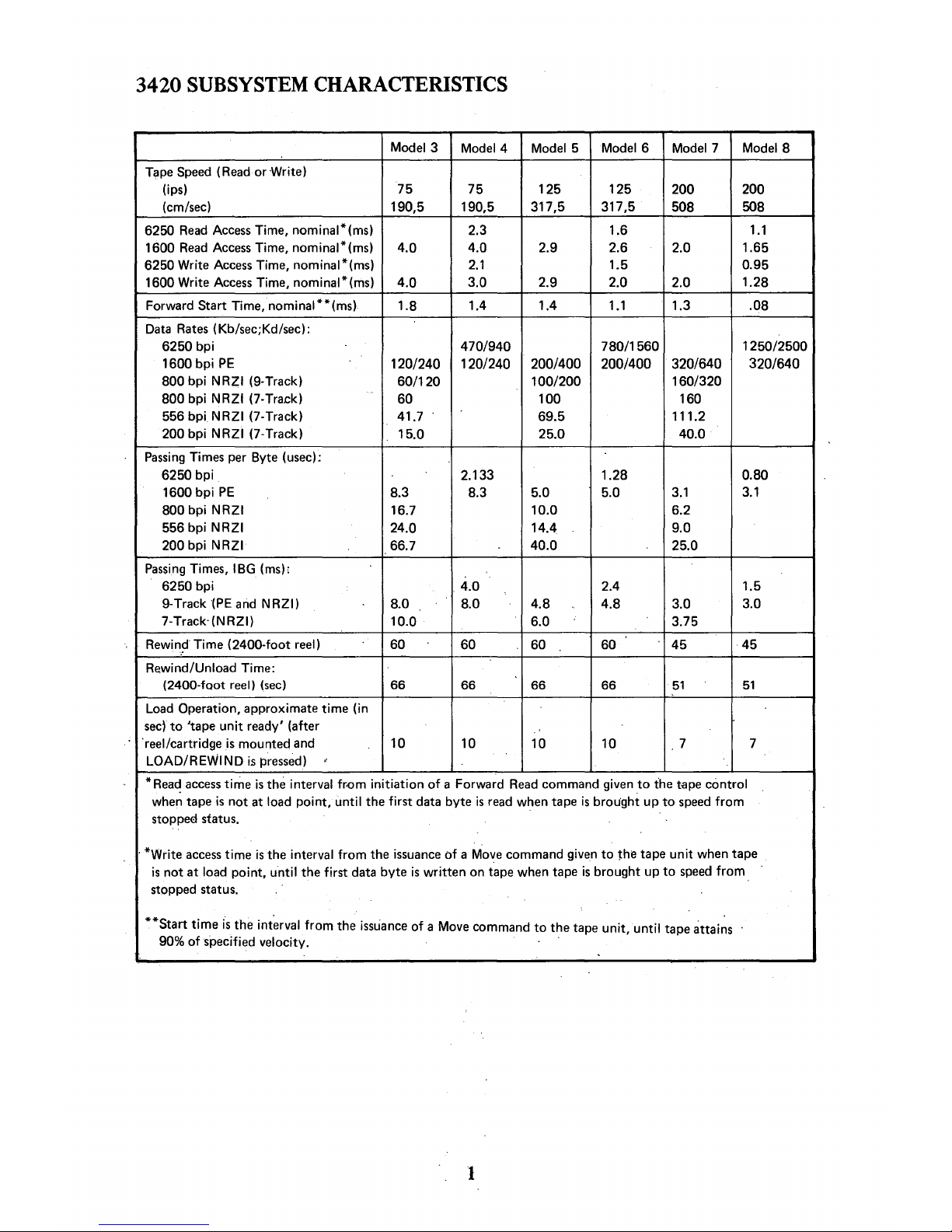
3420
SUBSYSTEM
CHARACTERISTICS
Model 3
Model 4 Model 5
Model 6
Model 7 Model 8
Tape
Speed
(Read
or Write)
(ips) 75
75
125 125
200 200
(cm/sec)
190,5
190,5
317,5 317,5
508
508
6250
Read
Access
Time, nominal*(ms)
2.3 1.6
1.1
1600
Read
Access
Time, nominal*(ms)
4.0
4.0
2.9 2.6 2.0
1.65
6250 Write
Access
Time, nominal*(ms)
2.1
1.5 0.95
1600
Write
Access
Time, nominal*(ms)
4.0
3.0
2.9 2.0
2.0
1.28
Forward
Start Time, nominal**(ms)
1.8 1.4 1.4
1.1
1.3 .08
Data
Rates
(Kb/sec;Kd/sec):
6250 bpi
470/940 780/1560
1250/2500
1600
bpi
PE
120/240
1201240
200/400 200/400
320/640 320/640
800
bpi NRZI (9-Track)
60/120
100/200 160/320
800
bpi NRZI (7-Tra.ck)
60
100 160
556 bpi NRZI (7-Track)
41.7 69.5
111.2
200 bpi NRZI (7-Track)
15.0
25.0 40.0
Passing
Times per Byte (usec):
6250 bpi
2.133 1.28
0.80
1600
bpi
PE
8.3
8.3
5.0
5.0
3.1
3.1
800 bpi NRZI
16.7 10.0 6.2
556 bpi
NRZI
24.0
14.4 9.0
200
bpi NRZI
66.7
40.0
25.0
Passing
Times, IBG (ms):
6250 bpi
4.0 2.4
1.5
9-Track(PE
and
NRZI)
8.0 8.0
4.8 4.8
3.0
3.0
7-Track'(NRZI)
10.0
6.0
3.75
Rewin.~·
Time (2400-foot reel) 60
60 60 60
45
45
Rewind/Unload Time:
(2400-fQot reel)
(sec)
66
66 66 66
51
51
Load
Operation, approximate time (in
sec)
to
'tape
unit
ready' (after
'reel/cartridge
is
mounted and
10
10 10 10
7
7
LOAD/REWIND
is
pressed)
*
Read
access
time
is
the interval fr.om initiation
of
a Forward
Read
command given
to
the
t-ape
control
whe~
tape
is
not
at load point, until the first data byte
is
read
when tape
is
brought up
to
speed
from
stoppe€!
status.
, *Write
access
time
is
the interval
from
the
issuance
of a Move
command given
to
~he
tape
unit
when tape
is
not
at load point,
until
the first data byte
is
written on tape when tape
is
brought up
to
speed
from
stopped status.
**Start
time
is
the
int~rval
from
the
issuance
of
a Move command
to
the tape unit, until tape
attai~s
90%
of
specified velocity. .
1
Page 7

Page 8
3803
MODEL 3 AND
3803
MODEL 1 DIFFERENCES
The Model 3
was
designed
to
attach
to
370/ 115s and 125s.
It
is
basically a
Modell
with
three major differences. These differences are required because the 115 and 125
don't
use
a standard 370 channel.
- ALUI
is
modified
to
interface with the channel on the 115 and 125 and translate the
activity to
370 channel sequences which the rest
of
the 3803 understands.
- Hardware logic called
AUTO DATA TRANSFER
is
provided
to
handle the data trans-
fer.
It
includes the byte counter.
- A 32-BYTE DATA BUFFER
is
provided for reading and writing. This large a buffet
is
required in the event
that
data crosses a page boundary. When this happens, time
is
required for ALUI to set the address
of
the new page back into the data address con-
trol in the 115 or 125.
The 3803 Model 3 tape subsystem connects to the Magnetic Tape Adaptor (MT
A)
inter-
face
of
system 3115 or system 3125. The term
MT
A interface refers
to
a set
of
lines over
which control and data signals are exchanged between the control unit and the
MT
A
portion
of
the system.
The basic
3803-3 Control Unit consists
of a MT
A interface attachment section, a data
buffer section, a microprogram section, a read section, a write section, a tape unit
inter-
face and a
CE
section.
I/O commands received from
CPU
through
MTA
are executed with microprograms resident in two independent read-only storage (ROS) units within the 3803-3 Control Unit.
One ROS controls the MTA interface lines while the other ROS controls the tape unit
interface.
The
3803-3 Control Unit operates in burst mode for all data transfers and executes com-
mands received across the interface, performing one command
on
a single tape unit at a
time.
When
a 3803 Mode13
is
taken offline, all functions from the control
to
the tape unit
become the same
as a Modell
3803.
3
Page 9

Page 10
RECORDING
PHILOSOPHY
Types
of
Codes:
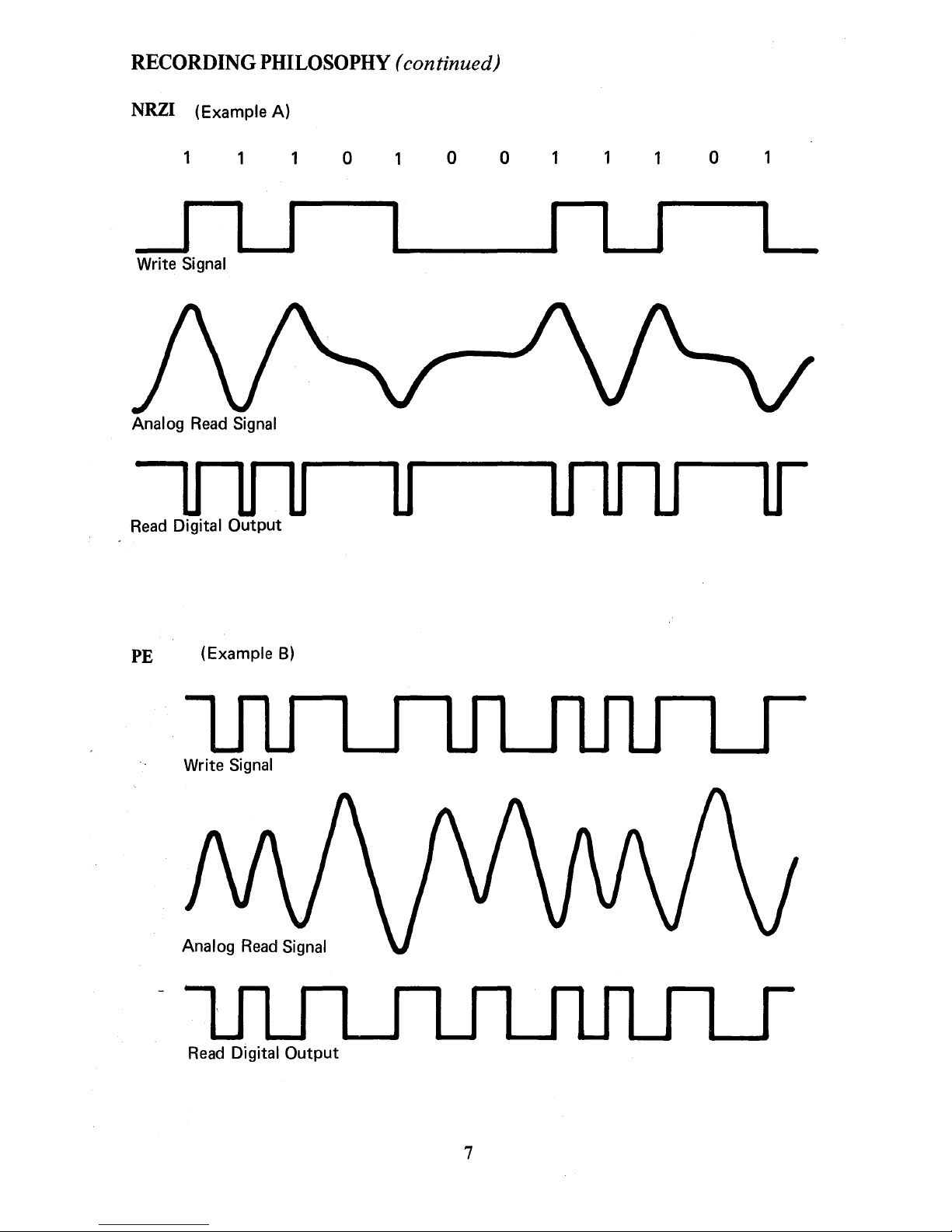
NRZI
PE
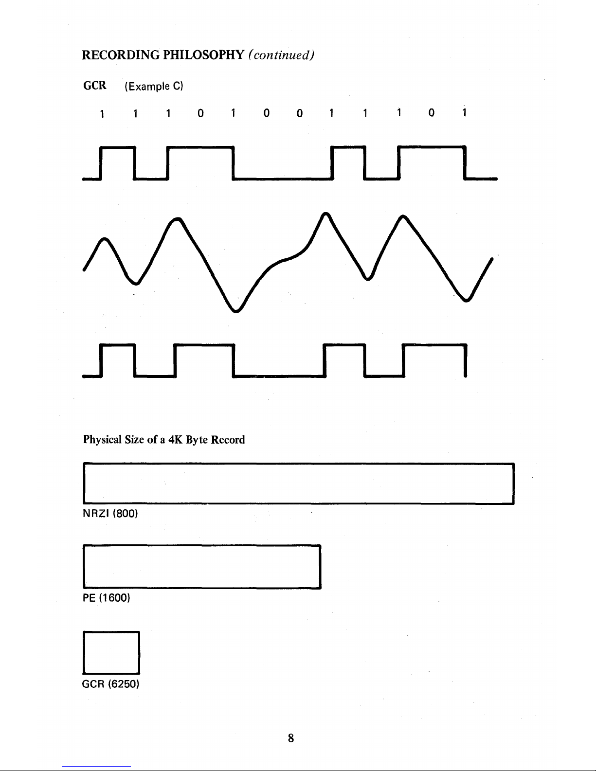
GCR
Non-Return
to
Zero Indicating
Phase Encoding
Group Coded Recording
The progression
of
IBM
digital recording from NRZI
to
PE to GRC
is
the result
of
IBM's
effort to provide the customer with
the lowest cost and highest reliability tape storage
devices.
NRZI coding utilizes a chnage in flux
to
indicate a one and no change
to
represent a zero.
NRZI tapes can be written in densities
of
200, 556 bpi in 7 -track format, and 800 bpi in
9-trace format. (See example A.)
PE coding utilizes a change
of
magnetic flux in the positive direction
to
indicate a one
and a change in the negative direction
to
indicate a zero. PE tapes are written
in
1600
bpi 9-track density only. (See example B.)
GCR coding utilizes a combination
of
NRZI and PE
to
achieve the highest density avail-
able on
IBM
drives. Density for GCR
is
effectively 6250 bpi. (See Example C.)
Group
Coded Recording -
6250
bpi
Group Coded Recording (GCR) offers many advantages over previously used recording
methods. This recording offers higher reliability even with existing tape libraries.
Greatly expanded error correction capability has been engineered into GCR. Higher
data rates and lower access times
give
higher throughput and reduced channel time,
re-
sulting in higher system performance. Data
is
compacted on tape, reducing rewind
times, shortening the length
of
tape required for a data set, reducing the number
of
reels, reducing mounts and dismounts, and improving overall tape handling. Other
advantages exist,
but
here
we
wish
to
discuss only the recording technique.
The data
is
still recorded in blocks, or groups
of
characters. A block
of
data may be
a single character or byte, or a number
of
bytes
as
determined by the programming
system used. The significant improvements in the GCR mode are:
1. The information data
is
recorded at an effective density
of
6250 bytes per inch.
2. The separation between blocks (IBG)
is
0.3 inch, and,
3. That simultaneous errors in any two
of
the nine tracks are corrected automatically.
A GCR block consists
of
a preamble, data and a postamble. The preamble and post-
amble are each
80 bytes long and serve to synchronize the read detection circuits in a
manner similar
to
previous 1600 bpi subsystems. The data portion
of
the block consists
of
the following:
5
Page 11
RECORDING
PHILOSOPHY
(continued)
1.
For every seven bytes
of
channel data, an
ECC
character (error correcting code)
is
generated and these eight bytes, called a data group, are encoded into ten
bytes, called a storage group, which are then written on the tape. There will be
as
many
of
these ten byte storage groups
as
there are multiples
of
seven channel
data bytes in the record block. The last group
of
the record block may contain
up to 158 storage groups.
2.
The remainder or last group
of
the channel data bytes (zero
to
six bytes)
is
encoded with whatever
"pad"
bytes are necessary, an auxiliary check character,
and the
ECC
character generated from these into a ten-byte residual group.
This residual data group
is
created for every block recorded, even though no
residual bytes are found in the record and will always be ten bytes long. The
auxiliary check character verifies read and write operations.
3. End
of
data
is
signaled by a unique subgroup
of
five
bytes immediately preceding
the residual group.
4. Following the residual group, a ten-byte
CRC
(Cyclic Redundancy Check) group
is
encoded. This group, with the auxiliary check character, ensures the integrity
of
the read and write operation including verifying any error corrections which
may have taken place.
5.
Interleaved into the recorded block, after every 158 storage groups,
is
a resync
burst. This burst allows the tape control unit
to
put
back into full operation any
track(s) which may have lost synchronization or dead tracked due to tape
defects. This action limits dead tracking for greater throughput.
6250 bpi does not relate
to
actual writing density on tape
but
to effective data density
Actual density (9042 bpi)
is
greater due
to
the formatting and enGoding,
but
this for-
matting and encoding
is
transparent
to
the user. The power
of
the format and encoding
method
is
such
that
reliable error correction occurs for any two tracks Simultaneously
in error. Also, tracks are not immediately dequeued or 'dead tracked' when an error
occurs
as
they were in the past.
It
is
thus conceivable that a block could have errors in
all nine tracks and appear
to
the user
to
be read error-free
so
long
as
only two tracks have
errors at any
given
instant.
6250 bpi, combined with 0.3 inch IBGs, provides for greatly improved channel data
rates and access times.
6
Page 12
RECORDING
PHILOSOPHY
( continued)
NRZI
(Example
A)
o
o o
o
--1
u
L
Write Signal
Analog
Read Signal
Read
Digital Output
PE
(Example
B)
Write
Signal
Read Digital Output
7
Page 13
RECORDING PHILOSOPHY
(continued)
GCR
(Example
C)
o
o
o
o
J
I
I
I ..-.-..
________
n
_______
1
L
J I
I
I
I
I
I
I
Physical Size
of
a 4K Byte Record
NRZI (800)
PE
(1600)
D
GCR
(6250)
8
Page 14
UNDERSTANDING
EREPI
EREP
is
designed to help you decide
if
you have a machine problem or defective media,
as
well
as
giving you a good idea
of
how your 3420s are performing. EREPI, with its
enhancement package,
is
even more useful than previous EREP versions. EREPI guide-
lines are presented here
to
assist the
CE
in managing his 3420 account.
IRD (Information Records Division)
is
using a criteria
of
one temporary write error per
5,000 SIOs and one temporary read error per 70,000 SIOs
as
a reference for an average
running
3420/3803 customer account.
We
agree with these numbers with the understand-
ing that they are intended
to
be a national average. They are not a certain indication
of
reliability
to
be obtained in individual accounts because
of
the influence
of
unmeasured
variables (ie, customer block size).
The IRD criteria
is
used in determining temporary read or write error criteria figures
on
the following flowcharts. EREPI parameters should be used
to
produce a 3420/3803
Summary Output with threshold values at one temporary read and fifteen temporary
write errors. These are suggested initial threshold values which
CE
may wish
to
change
later.
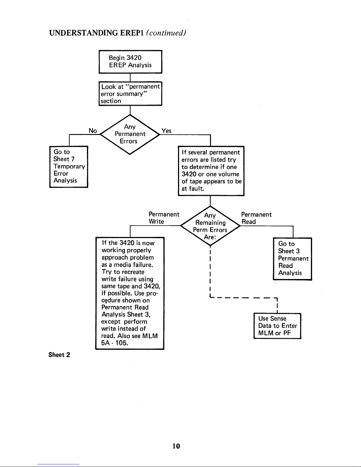
All
permanent errors should be investigated
to
an acceptable conclusion and all temporary
error quantities
not meeting
criteria
figures
should be recorded and tracked
to
determine
cause
of
outside-criteria conditions.
Sheet 1
9
Page 15
UNDERSTANDING EREPI
(continued)
Go
to
Sheet 7
Temporary
Error
Analysis
Sheet 2
Begin
3420
E R
EP
Analysis
Look
at
"permanent
error
summary"
section
Yes
Permanent
Write
If
the
3420
is
now
working properly
approach problem
as
a media failure.
Try
to
recreate
write failure using
same
tape
and
3420,
if possible.
Use
pro-
c~dure
shown
on
Permanent
Read
Analysis Sheet 3,
except
perform
wri
te
instead
of
read. Also see M
LM
5A - 105.
10
If
several
permanent
errors are listed
try
to
determine
if one
3420
or
one
volume
of
tape
appears
to
be
at
fault.
I
Permanent
Read
Go
to
Sheet
3
Permanent
Read
Analysis
L
______
,
I
I
Use
Sense
Data
to
Enter
MLM
or
PF
Page 16
UNDERSTANDING EREPI (continued)
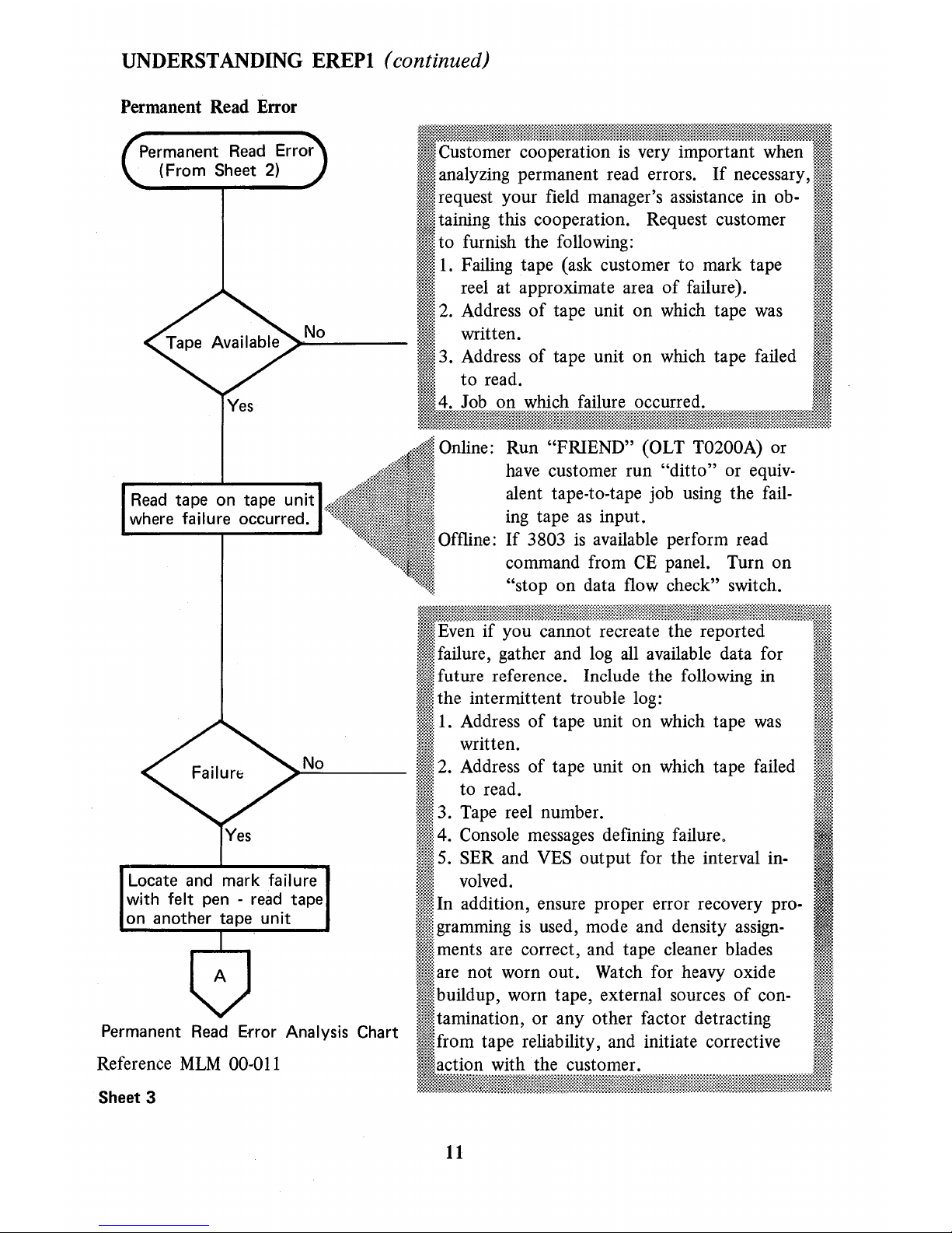
Permanent Read Error
Permanent
Read Error
(From
Sheet
2)
No
Yes
Read
tape
on
tape
unit
where failure
occurred.
No
Locate
and
mark failure
with felt pen - read
tape
on
another
tape
unit
Permanent
Read Error Analysis Chart
Reference
MLM
00-011
Sheet
3
Online: Run "FRIEND" (OLT T0200A) or
have customer run
"ditto"
or equivalent tape-to-tape job using the failing tape
as
input.
Offline:
If
3803
is
available perform read
command from
CE
panel. Turn on
"stop on data flow check" switch.
11
Page 17
UNDERSTANDING EREPI
(continued
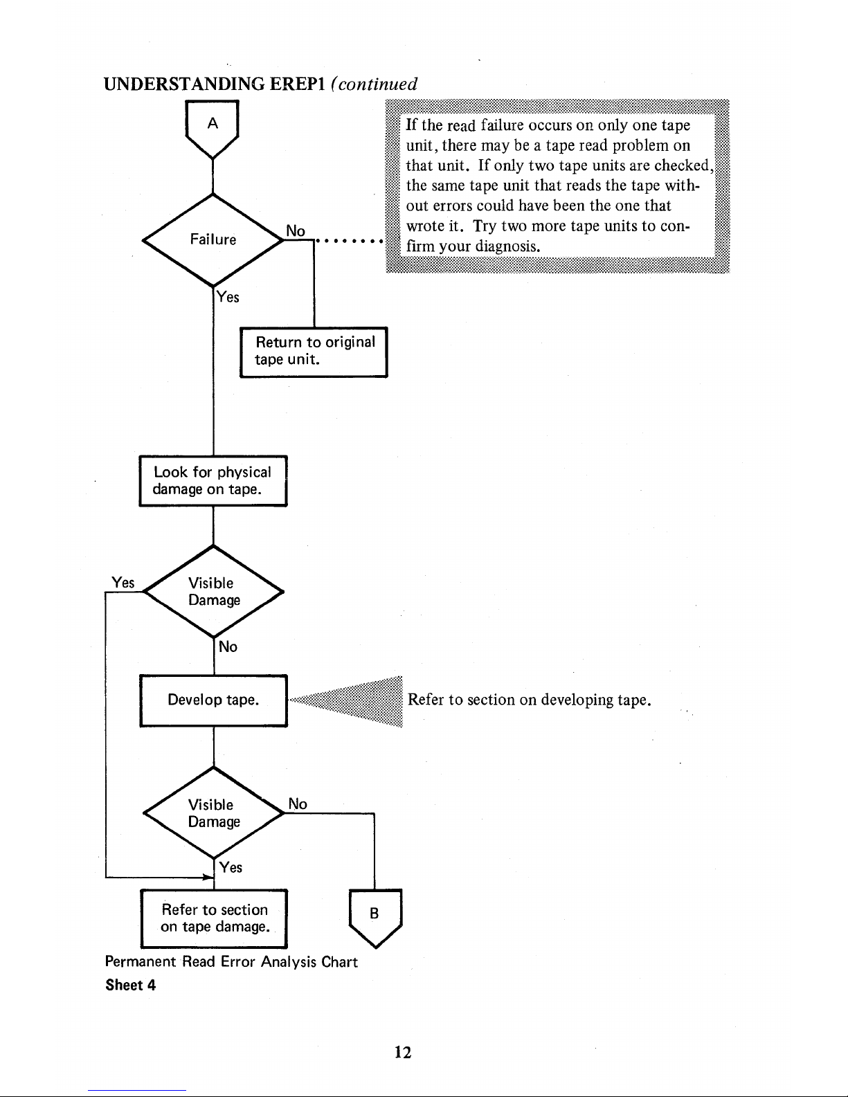
Yes
Return
to
original
tape
unit.
Look for physical
damage
on
tape.
Develop
tape.
Refer
to
section
on
tape
damage.
No
Permanent Read Error Analysis Chart
Sheet
4
Refer
to
section on developing tape.
12
Page 18
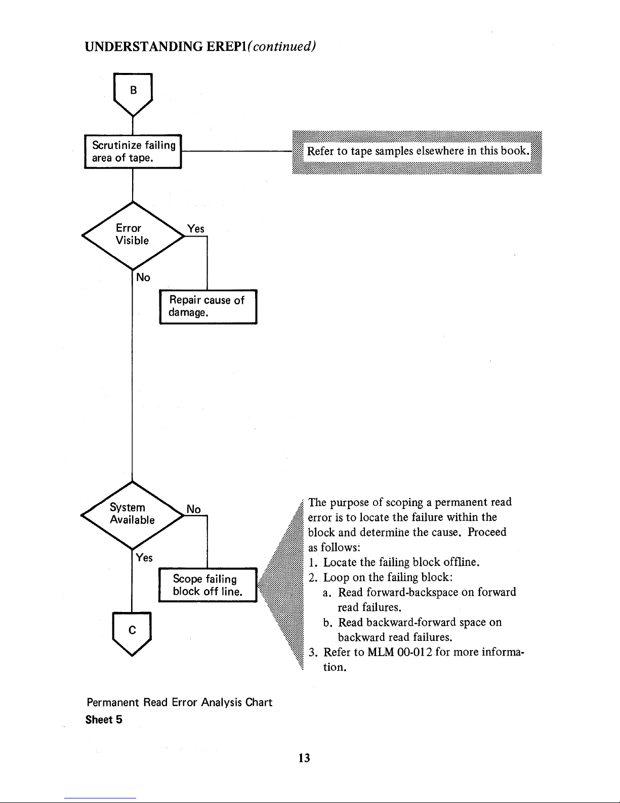
UNDERSTANDING
EREPl(
continued)
No
Yes
Repai
r cause of
damage.
Scope failing
block off line.
Permanent
Read
Error Analysis Chart
Sheet 5
: Refer
to
tape samples elsewhere in this book.
.
The
purpose
of
scoping a permanent read
error
is
to locate the failure within the
block and determine the cause.
Proceed
as
follows:
1.
Locate the failing block offline.
2. Loop on the failing block:
a. Read forward-backspace on forward
read failures.
b. Read backward-forward space on
backward read failures.
3.
Refer
to
MLM
00-012 for more informa-
tion.
13
Page 19
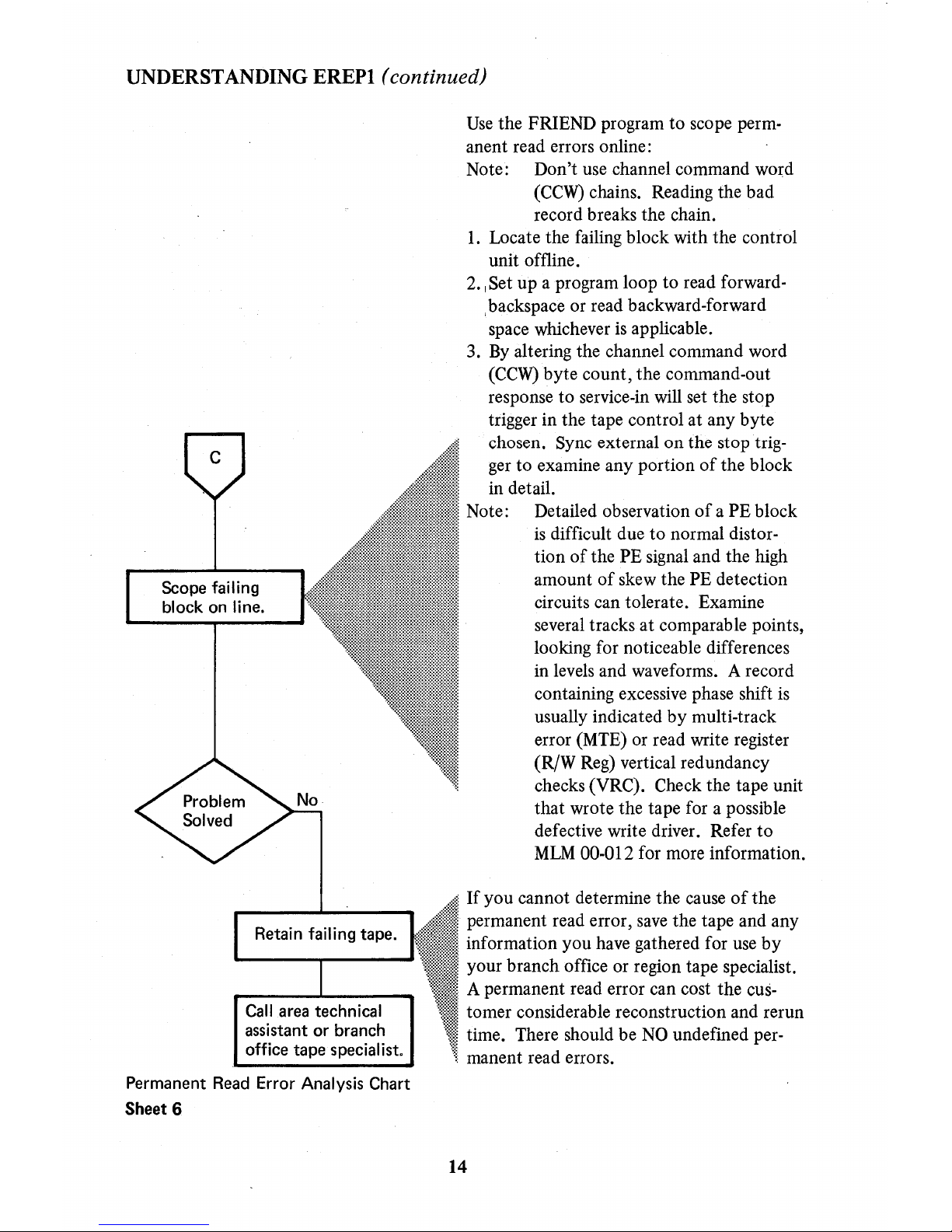
UNDERSTANDING
EREPI
(continued)
Scope failing
block
on
line.
Call
area technical
assistant
or
branch
office
tape
specialist.
Permanent
Read Error Analysis Chart
Sheet 6
Use
the FRIEND program to scope permanent read errors online:
Note: Don't use channel command word
(CCW)
chains. Reading the bad
record breaks the chain.
1.
Locate the failing block with the control
unit offline.
2.
I Set up a program loop to read forward-
I backspace or read backward-forward
space whichever
is
applicable.
3.
By
altering the channel command word
(CCW)
byte count, the command-out
response to service-in will set the stop
trigger in the tape control at any byte
chosen. Sync external on the stop
trig-
ger
to examine any portion
of
the block
in detail.
Note:
Detailed observation
of
a PE block
is
difficult due
to
normal distor-
tion
of
the PE signal and the high
amount
of
skew the PE detection
circuits can tolerate. Examine
several tracks
at
comparable points,
looking for noticeable differences
in levels and waveforms. A record
containing excessive phase shift
is
usually indicated by multi-track
error (MTE) or read write register
(R/W Reg) vertical redundancy
checks
(YRC). Check the tape unit
that wrote the tape for a possible
defective write driver. Refer
to
MLM
00-012 for more information.
·
If
you cannot determine the cause
of
the
permanent read error,
save
the tape and any
: information you have gathered for
use
by
· your branch office or region tape specialist.
· A permanent read error can cost the cus: tomer considerable reconstruction and rerun
time. There should be
NO
undefined per-
manent read errors.
14
Page 20
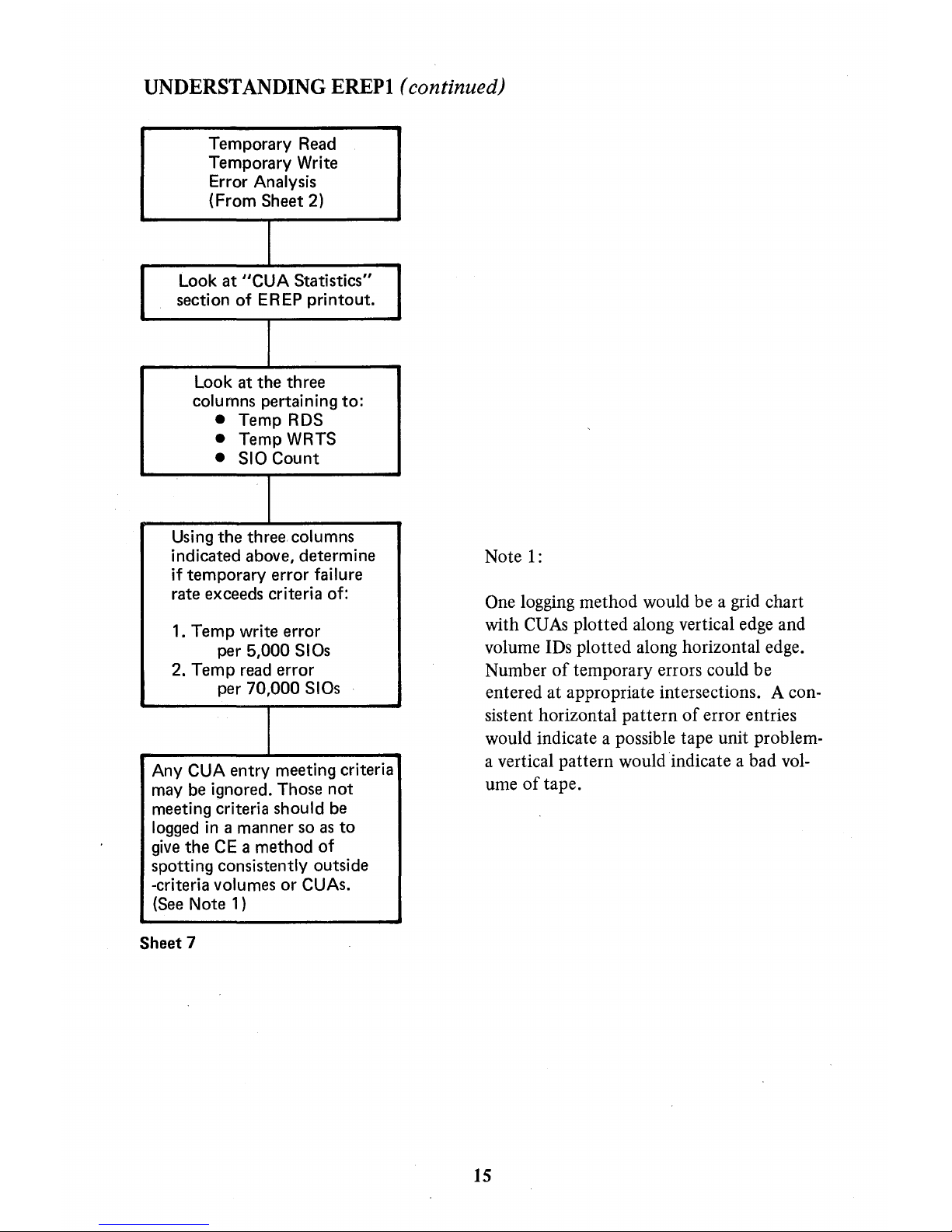
UNDERSTANDING EREPI
(continued)
Temporary Read
Temporary Write
Error
Analysis
(From Sheet 2)
I
Look
at
"CUA
Statistics"
section
of
EREP
printout.
I
Look
at
the
three
columns pertaining
to:
• Temp RDS
•
Temp WRTS
•
SIO
Count
I
Using
the
three
columns
indicated above, determine
if
temporary
error
failure
rate exceeds criteria of:
1.
Temp
write error
per
5,000
SIOs
2.
Temp
read error
per
70,000
SIOs
I
Any CUA
entry
meeting criteria
may be ignored. Those
not
meeting criteria should be
logged
in
a manner so
as
to
give
the
CE a
method
of
spotting consistently outside
-criteria
volumes
or
CUAs.
(See Note 1)
Sheet 7
Note
1:
One logging
method
would
be
a grid chart
with
CUAs
plotted
along vertical edge
and
volume IDs
plotted
along horizontal edge.
Number
of
temporary
errors could
be
entered
at
appropriate intersections. A con-
sistent
horizontal
pattern
of
error entries
would indicate a possible
tape
unit
problem-
a vertical
pattern
would
indicate a bad
vol-
ume
of
tape.
15
Page 21

Page 22
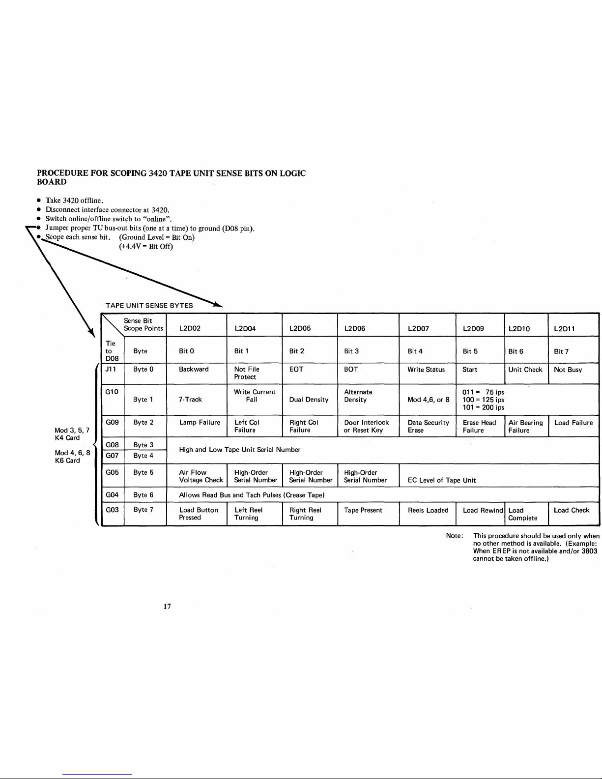
PROCEDURE
FOR
SCOPING
3420
TAPE UNIT SENSE BITS ON LOGIC
BOARD
• Take
3420
offline.
• Disconnect interface connector at 3420.
•
Switch online/offline switch
to
"online".
• Jumper proper
TV
bus-out bits (oIle at a time)
to
ground (D08 pin).
• Scope each sense bit. (Ground Level = Bit On)
Mod 3, 5, 7
K4
Card
<C
~
(+4.4V = Bit Off)
TAPE
UNIT
SENSE BYTES
~
SensoBit
Scope
Points
L2D02
Tie
to
Byte
Bit
0
D08
J11
Byte 0 Backward
G10
Byte 1 7-Track
G09
Byte 2
Lamp Failure
L2D04
Bit
1
Not File
Protect
Write
Current
Fail
Left Col
Failure
L2D05
Bit
2
EOT
Dual Density
Right
Col
Failure
Mod
4,6,8
K6
Card
G08
G07
Byte 3
Byte 4
High and
Low
Tape
Unit
Serial Number
G05
Byte 5
Air
Flow
High-Order High-Order
Voltage Check Serial Number
Serial Number
G04 Byte 6
Allows
Read
Bus
and
Tach
Pulses
(Crease
Tape)
G03
Byte 7
Load
Button
Left
Reel
Right
Reel
Pressed
Turning Turning
,
17
L2D06
Bit 3
BOT
Alternate
Density
Door
Interlock
or
Reset
Key
High-Order
Serial
Number
Tape
Present
L2D07
L2D09
L2D10
L2D11
Bit
4
Bit 5
Bit
6
Bit
7
Write Status Start
Unit
Check
Not
Busy
011
= 75
ips
Mod 4,6, or 8 100 = 125 ips
101
= 200 ips
Data Security
Erase
Head
Air
Bearing
Load Failure
Erase
Failure Failure
EC
Level
of
Tape
Unit
Reels
Loaded
Load Rewind
Load
Load
Check
Complete
Note: This procedure should
be
used
only
when
no other method
is
available. (Example:
When
EREP
is
not
available and/or 3803
cannot
be
taken offline.)
Page 23
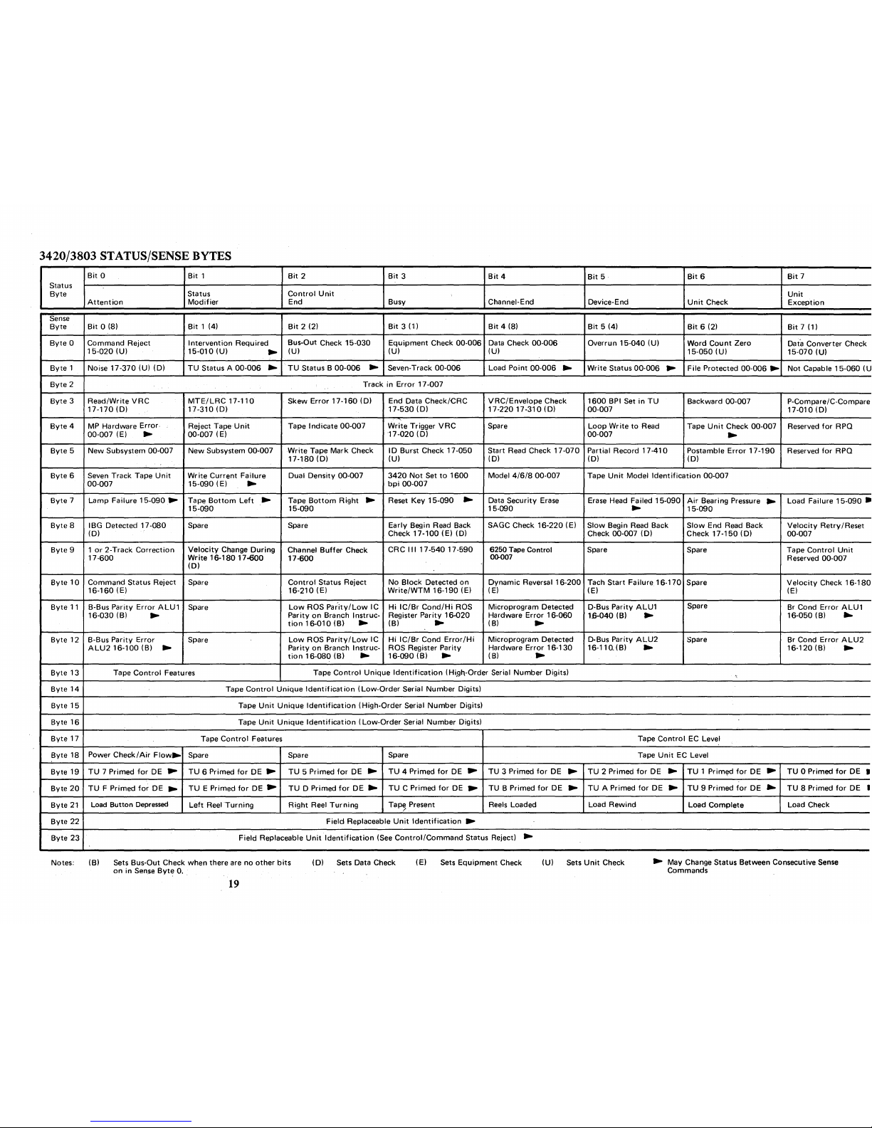
3420/3803
STATUS/SENSE BYTES
Bit
0
Bit
1
Bit
2
Bit
3
Bit
4
Bit
5·
Bit
6
Bit
7
Status
Byte
Status
Control
Unit
Unit
Attention
Modifier
End Busy Channel-End
Device-End
Unit
Check
Exception
Sense
Byte
Bit
0 (8)
Bit
1 (4)
Bit
2 (2)
Bit
3 (1)
Bit
4 (8)
Bit
5 (4)
Bit
6 (2)
Bit
7 (1)
Byte 0 Command
Reject
Intervention
Required
Bus-Out Check
15-030
Equipment
Check
00-006
Data Check
00-006
Overrun
15-040
(U)
Word
Count
Zero
Data Converter Check
15-020
(U)
15-010
(U)
~
(U)
(U)
(U)
15-050
(U)
15-070
(U)
Byte
1
Noise
17-370
(U)
(D)
TU
Status A
00-006
~
.'.
TU
Status B
00-006
~
Seven-Track
00-006
Load
Point
00-006
~
Write
Status
00-006
~
File Protected
00-006 ~ Not
Capable
15-060
(U:
Byte
2
Track
in
Error
17-007
Byte 3 Read/Write
VRC
MTEILRC
17-110
Skew
Error
17-160
(D)
End Data
Check/CRC
VRC/Envelope
Check
1600
BPI Set
in
TU
Backward 00-007
P-Compare/C-Compare
17-170
(D)
17-310
(D)
17-530
(D)
17-22017-310
(D)
00-007
17-010
(D)
Byte
4
MP Hardware Error,
Reject Tape
Unit
Tape
Indicate
00-007
Write
Trigger
VRC
Spare
Loop
Write
to
Read
Tape
Unit
Check
00-007
Reserved
for
RPQ
00-007 (E)
~
00-007 (E)
17-020
(D)
00-007
~
Byte 5 New
Subsystem 00-007
New
Subsystem 00-007
Write
Tape
Mark
Check
ID
Burst Check
17-050
Start Read Check
17-070
Partial Record
17-410
Postamble
Error
17-190
Reserved
for
RPQ
17-180
(D)
(U) (D) (D) (D)
Byte
6 Seven
Track
Tape
Unit
Write
Current
Failure
Dual
Density
00-007
3420
Not
Set
to
1600
Model
4/6/8
00-007
Tape
Unit
Model
Identification
00-007
00-007
15-090
(E)
~
bpi
00-007
Byte 7 Lamp
Failure
15-090
~
Tape
Bottom
Left
~
Tape
Bottom
Right ~ Reset
Key
15-090
~
Data
Security
Erase Erase Head Failed
15-090
Air
Bearing Pressure
~
Load Failure
15-090
•
15-090
15-090
15-090
~
15-090
Byte
8 I
BG
Detected 17
-080
Spare
Spare
Early
Begin Read Back SAGC Check
16-220
(E)
Slow
Begin Read Back
Slow
End Read Back
Velocity
Retry/Reset
(D)
Check
17-100
(E) (D) Check 00-007 (D)
Check
17-150
(D)
00-007
Byte
9 1
or
2-Track
Correction
Velocity
Change
During
Channel
Buffer
Check
CRC
III
17-54017-590
6250
Tape
Control Spare Spare
Tape
Control
Unit
17-600
Write
16-180
17-600
17-600
00-007
Reserved 00-007
(D)
Byte
10
Command
Status Reject Spare
Control
Status Reject
No
Block
Detected
on
Dynamic
Reversal
16-200
Tach
Start
Failure
16-170
Spare
Velocity
Check
16-180
16-160
(E)
16-210
(E)
Write/WTM
16-190
(E)
(E)
(E) (E)
Byte
11
B-Bus
Parity
Error
ALU1
Spare
Low
HOS
Parity/Low
IC Hi
IC/Br
Cond/Hi
ROS
Microprogram
Detected
D-Bus
Parity
ALU1
Spare
Br Cond
Error
ALU1
16-030
(B)
~
Parity
on
Branch Instruc-
Register
Parity
16-020
Hardware
Error
16-060
1.6-040 (B)
~
16-050
(B)
~
tion
16-010
(B)
~
(B)
~
(B)
~
Byte
12
B-Bus
Parity
Error
Spare
Low
ROS
Parity/Low
IC
Hi
IC/Br
Cond
Error/Hi
Microprogram
Detected
D-Bus Parity
ALU2
Spare
Br Cond
Error
ALU2
ALU2
16-100
(B)
~
Parity
on
Branch Instruc- ROS Register
Parity
Hardware
Error
16-130
16-11Q(B)
~
16-120
(B)
~
tion
16-080
(B)
~
16-090
(B)
~
(B)
~
Byte
13
Tape
Control
Features
Tape
Control
Unique
Identification
(Hi,gh-Order Serial
Number
Digits)
Byte
14
Tape
Control
Unique
Identificat
ion
(Low-Order
Serial
Number
Digits)
Byte
15
Tape
Unit
Unique
Identification
(High-Order
Serial
Number
Digits)
Byte
16
Tape
Unit
Unique
Identification
(Low-Order
Serial
Number
Digits)
Byte
17
Tape
Control
Features
Tape
Control
EC Level
Byte
18 Power
Check/Air
Flow.
Spare Spare
Spare
Tape
Unit
EC
Level
Byte
19
TU
7 Primed
for
DE
~
TU
6 Primed
for
DE
~
TU
5 Primed
for
DE
~
TU
4 Primed
for
DE ~ TU
3 Primed
for
DE ~ TU
2 Primed
for
DE ~ TU
1 Priml;ld
for
DE ~ TU
0 Primed
for
DE
•
Byte
20
TU
F Primed
for
DE
~
TU
E Primed
for
DE
~
TU
0 Primed
for
DE
~
TU
C Primed
for
DE ~ TU
B Primed
for
DE ~ TU
A Primed
for
DE ~ TU
9 Primed
for
DE
~
TU
8 Primed
for
DE
I
Byte
21
Load Button
Depressed
Left
Reel
Turning
Right
Reel
Turning
Tap~
Present
Reels Loaded
Load
Rewind
Load
Complete
Load Check
Byte
22
Field
Replaceable
Unit
Identification
•
Byte
23
Field
Replaceable
Unit
Identification
(See
Control/Command
Status Reject)
~
Notes: (B) Sets Bus-Out Check
when
there
are
no
other
bits
on
in Sense
Byte
O.
(D) Sets Data Check (E) Sets
Equipment
Check (U) Sets
Unit
Check
~
May Change Status Between Consecutive Sense
Commands
19
Page 24
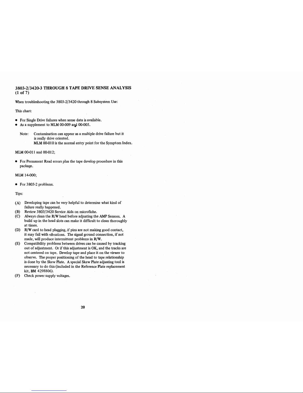
3803-2/3420-3 THROUGH 8 TAPE DRIVE SENSE ANALYSIS
(1
of
7)
When troubleshooting the 3803-2/3420 through 8 Subsystem Use:
This chart:
• For Single Drive failures when sense data
is
available.
•
As
a supplement
to
MLM
00-009 aqp 00-005.
Note: Contamination can appear
as
a multiple drive failure
but
it
is
really drive oriented.
MLM
00-010
is
the normal entry point for the Symptom Index.
MLM
00-011 and 00-012;
•
For
Permanent Read errors plus the tape develop procedure in this
package.
MLM
14-000;
•
For
3803-2 problems.
Tips:
(A) Developing tape can be very helpful
to
determine what kind
of
failure really happened.
(B) Review
3803/3420 Service Aids on microfiche.
(C) Always clean the
R/W
head before adjusting the
AMP
Sensors. A
build up in the head slots can make
it
difficult
to
clean thoroughly
at
times.
(D)
R!W
card
to
head plugging,
if
pins are
not
making good contact,
it
may fail with vibrations. The signal ground connection,
if
not
made, will produce intermittent problems in
R/W.
(E) Compatibility problems between drives can be caused
by
tracking
out
of
adjustment. Or
if
this adjustment is OK, and the tracks are
not
centered
on
tape. Develop tape and place
it
on
the viewer
to
observe. The proper positioning
of
the head to tape relationship
is
done
by
the Skew Plate. A special Skew Plate adjusting tool
is
necessary
to
do this (included in the Reference Plate replacement
kit,
BM
4298806).
(F) Check power supply voltages.
20
Page 25

3803-2/3420-3 THROUGH 8 TAPE DRIVE SENSE ANALYSIS
(2
of
7)
(continued)
Note: Sense byte bits are in the order
of
their importance except bits in byte 10.
No
No
Recheck
Symptoms
No
Yes
(A)
If
Ready
is
Off,
Go
to
Sense
Byte
7, Under
Entry
Point
"Au.
(B)
If
Ready
is
On, Go
to
MLM
15·010.
(C)
If
Not
Ready, Go
to
15-090.
(A)
Auto
Cleaner Binding.
(B)
Not
Able
to
Read
Track 1 (6250)
or
Track P 1600.
Dirty
or
Defective
Head.
(C)
Damaged
Tape in Inverse TM Area,
But
After
SAGC Area.
(D)
Read
Card
or
Cable
Loose
(E)
A1
L2
(F) ECA 073
(G) 15-060
(A) Write -
Auto
Cleaner Binding
and
Sticking Over Head.
Note:
SAGC
Not
On.
(B) Write -
10 Burst and SAGC,
Dirty
or Defective
Head
and
Could
be
Edge
Damage
on Tape
at
or
Near
LP.
(C)
Read
or
Write Card.
(D)
Read
Cable Loose.
(E)
5B-000
(F) 17-050
21
[FE127601)
Page 26
3803-2/3420-3 THROUGH 8 TAPE
DRNE
SENSE ANALYSIS
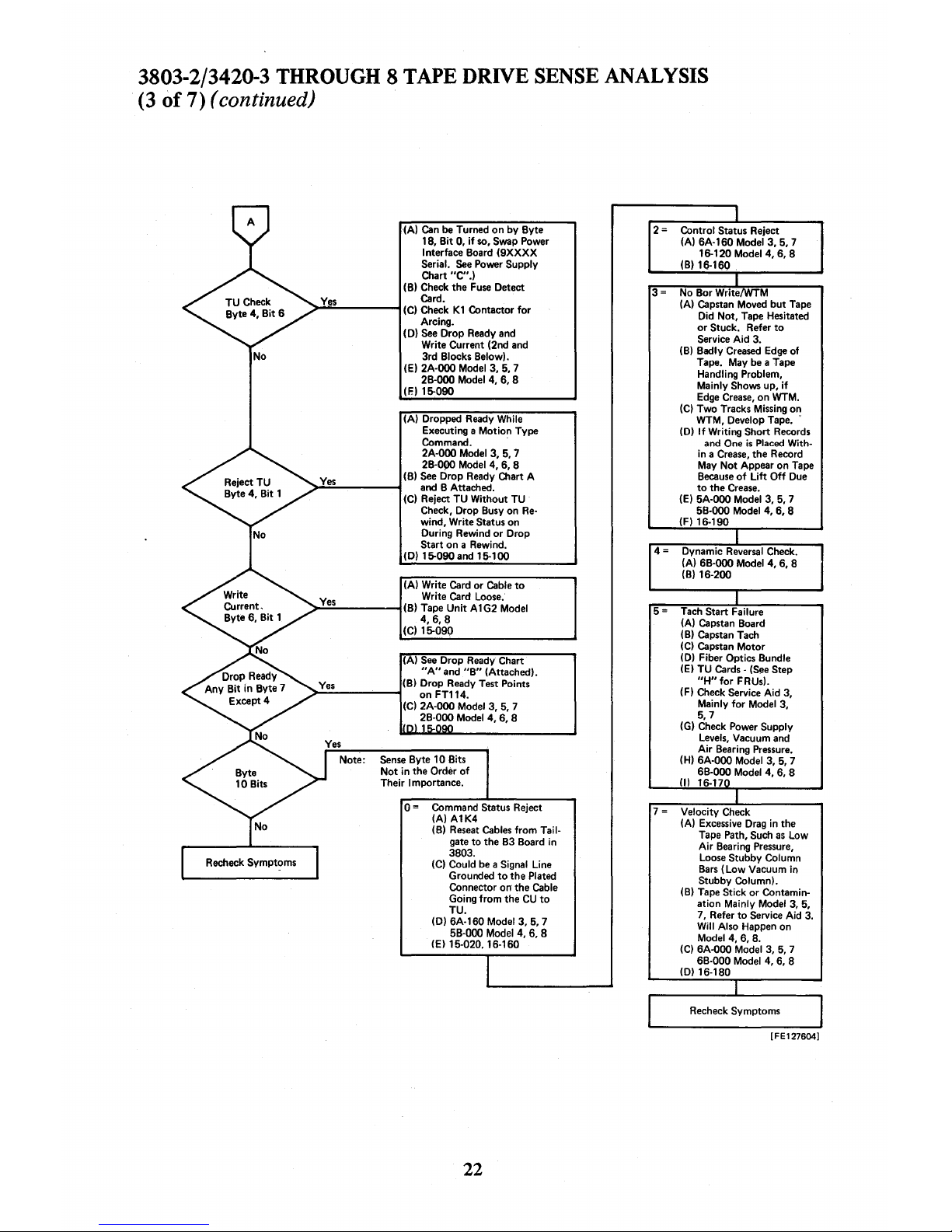
(3
of
7)
(continued)
No
(A)
Can
be
Turned
on
by
Byte
18,
Bit
0,
if
so,
Swap Power
Interface Board
(9XXXX
Serial.
See
Power Supply
Chart
"C".)
(B) Check the
Fuse
Detect
Ye~
Card.
>~-----1
(C) Check
Kl
Contactor
for
Arcing.
(D)
See
Drop Ready and
Write Current (2nd
and
3rd Blocks Below).
(E) 2A·000 Model 3, 5, 7
2B·000 Model 4, 6, 8
(E) 15-090
(A) Dropped Ready While
Executing a Motion Type
Command. .
2A·000 Model 3, 5, 7
2B·000 Model 4, 6, 8
(B)
See
Drop Ready Chart A
>;.::.-----1
and
B Attached.
(C) Reject
TU
Without TU
Check, Drop Busy on
Re·
wind, Write Status on
During Rewind
or
Drop
Start on a Rewind.
(D)
15-090
and
15-100
(A) Write Card or Cable
to
Write Card
Loose."
>:..::::..-----1 (B) Tape
Unit
A 1 G2 Model
4,6,8
(C) 15-090
(A)
See
Drop
Ready
Chart
"A"
and
"B"
(Attached).
(B) Drop Ready Test Points
>..;;.;;..-----1 on
FTl14.
(C)
2A·000 Model 3, 5, 7
2B·000 Model 4, 6, 8
Sense
Byte 10 Bits
Not
in the Order
of
Their Importance.
0=
Command Status Reject
(A)A1K4
(B)
Reseat
Cables
from
Tail·
gate
to
the B3 Board in
3803.
(C) Could
be
a Signal Line
Grounded
to
the Plated
Connector
on
the Cable
Going
from
the
CU
to
TU.
(D) 6A·160
Modell,
5, 7
5B·000 Model 4, 6, 8
(E)
15-020.16·160
22
No Bor WritelWTM
(A) Capstan Moved
but
Tape
Did
Not,
Tape Hesitated
or
Stuck. Refer
to
Service
Aid
3.
(B)
Badly
Creased
Edge
of
Tape. May
be
a Tape
Handling Problem,
Mainly
Shows up,
if
Edge
Crease,
on WTM.
(C)
Two Tracks Missing on
WTM, Develop Tape. .
(D)
If
Writing Short Records
and
One
is
Placed
With·
in a
Crease,
the Record
May
Not
Appear on Tape
Because
of
Lift
Off
Due
to
the
Crease.
(E) 5A·000 Model
3,5,7
5B·000 Model 4, 6, 8
(F)
16·190
5 = Tach Start Failure
(A) Capstan Board
(B) Capstan Tach
(C)
Capstan
Motor
(D) Fiber Optics Bundle
(E) TU Cards·
(See
Step
"H"
for
FRUs).
(F) Check Service
Aid
3,
Mainly
for
Model 3,
5,7
(G) Check Power Supply
Levels,
Vacuum and
Air
Bearing
Pressure.
(H)
6A·000
Model 3, 5, 7
6B·000 Model 4, 6, 8
(I) 16-17
7 = Velocity Check
(A)
Excessive
Drag
in the
Tape
Path, Such
as
Low
Air
Bearing
Pressure,
Loose Stubby Column
Bars
(Low
Vacuum in
Stubby
Column).
(B) Tape Stick
or
Contamin·
ation Mainly Model 3, 5,
7,
Refer
to
Service Aid 3.
Will
Also Happen on
Model 4, 6, 8.
(C)
6A·000 Model 3,
5,
7
6B·000 Model 4, 6, 8
(0)
16·180
[FE127604]
Page 27
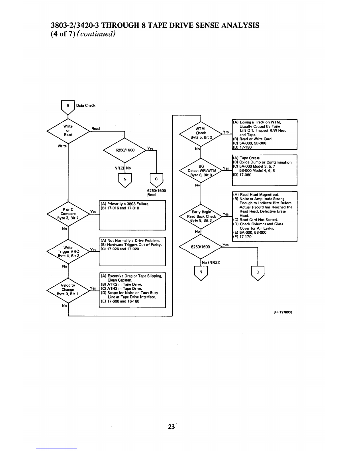
3803-2/3420-3
THROUGH 8 TAPE
DRIVE
SENSE
ANALYSIS
(4
of
7) (continued)
6250/1600
Read
(A)
Primarily a 3803 Failure.
(B)
17-016 and 17-010
(A)
Not
Normally
a Drive Problem_
(B) Hardware Triggers
Out
of
Parity.
Ie)
17-026
and
17-020
(A)
Excessive Drag or Tape Slipping,
Clean Capstan.
(B) A 1
K2
in Tape Drive.
(C)
A1H2
in Tape Drive.
(D) Scope
for
Noise on Tach Busy
line
at
Tape Drive Interface.
(E) 17-600 and 16-180
23
(A) Losing a Track
on
WTM,
Usually
Caused
by
Tape
Lift
Off.
Inspect R/W
Head
and
Tape_
(B)
Read
or
Write Card.
(C)
5A-ooo,5B-000
(D) 17-180
(A) Tape
Crease
(B) Oxide Dump
or
Contamination
(C)
5A-000 Model 3,
5,
7
5B-000 Model 4, 6, 8
(D)
17-080
(A)
Read
Head
Magnetized.
(B) Noise
at
Amplitude
Strong
Enough
to
Indicate Bits Before
Actual Record
has
Reached the
Read
Head, Defective
Erase
Head.
(C)
Read
Card
Not
Seated.
(D)
Check Columns and
Glass
Cover
for
Air
Leaks.
(E)
5A-000, 5B-000
(F) 17-170
[FE127603]
Page 28
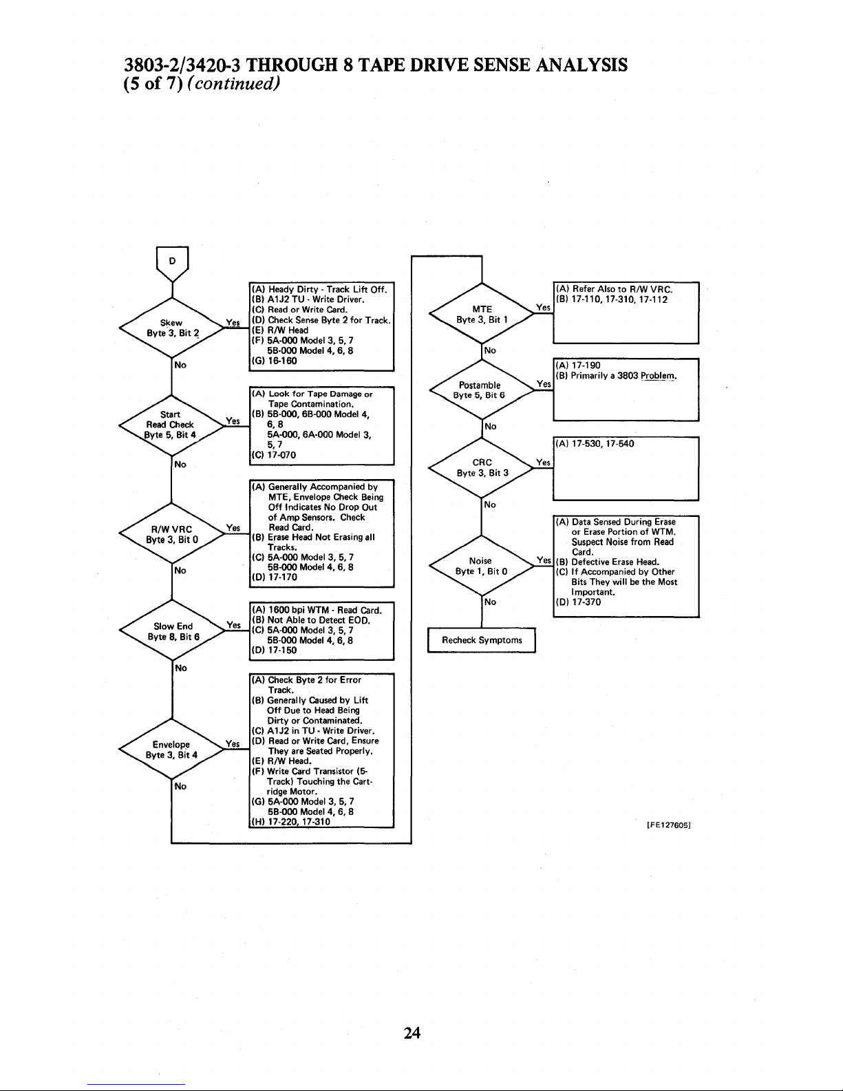
3803-2/3420-3
THROUGH 8 TAPE
DRIVE
SENSE
ANALYSIS
(S
of
7) (continued)
No
(A) Heady
Dirty
- Track
Lift
Off.
(B) A1J2 TU - Write Driver.
(C)
Read
or
Write
Card.
(D) Check
Sense
Byte 2
for
Track.
(E)
RIW
Head
(F) 5A-000 Model 3,
5,7
5B-000 Model 4, 6, 8
(G) 16-160
(A)
Look
for
Tape
Damage
or
Tape Contamination.
(B)
5B-000, 6B-000 Model 4,
6,8
5A-000,
6A-OOO
Model 3,
5,7
(C) 17-070
(A) Generally Accompanied
by
MTE, Envelope Check
Being
Off
Indicates No Drop Out
of
Amp
Sensors.
Check
Read
Card.
(B)
Erase
Head
Not
Erasing all
Tracks.
(C)
5A-000 Model 3, 5, 7
5B-000 Model 4, 6, 8
(D)
17-170
(A) 1600 bpi WTM -
Read
Card.
(B)
Not
Able
to
Detect EOO.
(C) 5A-000 Model 3,
5,
7
5B-000 Model 4, 6, 8
(D)
17-150
(A) Check Byte 2
for
Error
Track.
(B)
Generally
Caused
by
Lift
Off
Due
to
Head
Being
Dirty
or
Contaminated.
(C) A1J2 in TU
- Write Driver.
(D)
Read
or Write Card, Ensure
They
are
Seated
Properly.
(E) RIW Head.
(F) Write Card Transistor
(5-
Track) Touching the Cartridge Motor.
(G)
5A-000 Model 3,
5,
7
5B-000 Model 4, 6, 8
(H)
17-220 17-310
24
(A) Refer Also
to
R/W VRC.
(B)
17-110,17-310,17-112
Yes
(A) 17-190
Yes
(B) Primarily a 3803
Probl~l!'.
(A) 17-530,17-540
(A) Data
Sensed
During
Erase
or
Erase
Portion
of
WTM.
Suspect Noise from
Read
Card.
Yes
(B) Defective
Erase
Head.
(C)
If
Accompanied
by
Other
Bits They
will
be
the Most
Important.
(D)
17-370
[FE127605]
Page 29
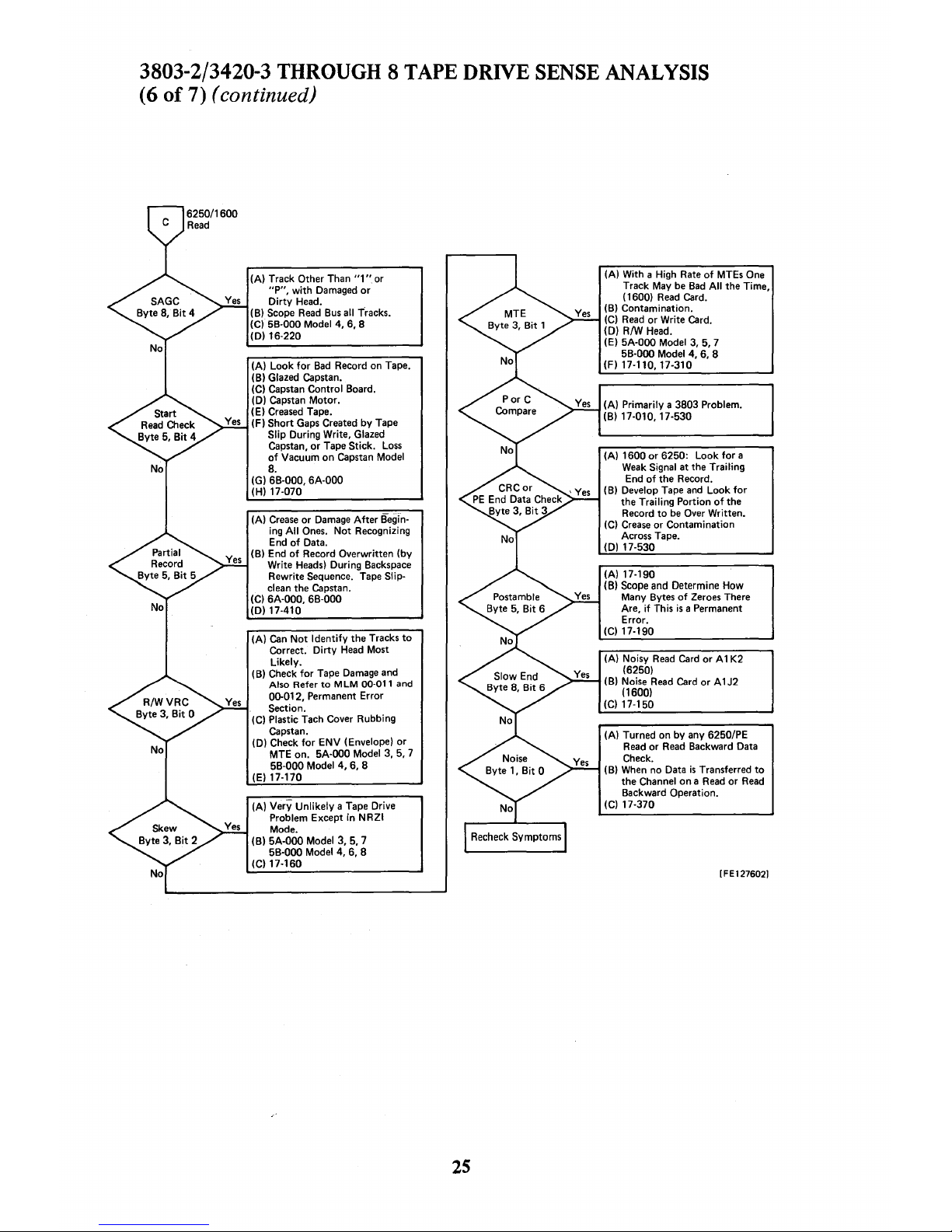
3803-2/3420-3
THROUGH 8 TAPE
DRNE
SENSE
ANALYSIS
(6
of
7)
(continued)
(A) Track Other Than
"1"
or
"P",
with
Damaged
or
Dirty
Head.
(B)
Scope
Read
Bus
all Tracks.
(C)
58·000
Model
4,6,8
(D) 16·220
(A)
Look
for
Bad
Record on Tape.
(B)
Glazed Capstan.
(C) Capstan Control Board.
(D) Capstan
Motor.
(E)
Creased
Tape.
(F)
Short
Gaps Created
by
Tape
Slip During Write, Glazed
Capstan,
or
Tape Stick.
Loss
of
Vacuum
on
Capstan Model
8.
(G) 6B·000,
6A·000
(H) 17·070
(A)
Crease
or
Damage
After
Begin·
ing
All
Ones.
Not
Recognizing
End
of
Data.
(B) End
of
Record Overwritten (by
Write Heads) During Backspace
Rewrite
Sequence. Tape Slip·
clean the Capstan.
(C) 6A·000, 6B·000
(D) 17·410
(A)
Can
Not
Identify
the
Tracks
to
Correct.
Dirty
Head
Most
Likely.
(8) Check
for
Tape
Damage
and
Also Refer
to
MLM
00·011
and
00-012, Permanent Error
Section.
(C)
Plastic Tach Cover Rubbing
Capstan.
(D)
Check
for
ENV
(Envelope)
or
MTE on.
5A·QOO
Model 3, 5, 7
5B·000 Model
4,
6, 8
(E)
17·170
(A)
Very
Unlikely
a Tape Drive
Problem Except in
NRZI
Mode.
(B)
5A·000
Model
3,5,7
5B·000 Model 4, 6, 8
(C) 17·160
2S
(A) With a High Rate
of
MTEs One
Track May
be
Bad
All
the Time,
(1600)
Read
Card.
(B) Contamination.
(C)
Read
or
Write Card.
(D) R/W Head.
(E)
5A·000
Model 3,
5,7
5B·000 Model 4, 6, 8
(F)
17·110,17·310
(A)
Primarily a 3803 Problem.
(B)
17·010, 17·530
(A)
1600
or
6250: Look
for
a
Weak
Signal at the Trailing
End
of
the
Record.
(B)
Develop Tape
and
Look
for
the Trailing Portion
of
the
Record
to
be
Over Written.
(C)
Crease
or
Contamination
Across Tape.
(D)
17·530
(A) 17·190
(B) Scope and Determine How
Many Bytes
of
Zeroes There
Are,
if
This
is
a Permanent
Error.
(C)
17·190
(A) Noisy
Read
Card
or
A 1 K2
(6250)
(B) Noise
Read
Card
or
A 1 J2
(1600)
(C)
17·150
(A) Turned on by any 6250/PE
Read
or
Read
Backward Data
Check.
(B)
When
no Data
is
Transferred
to
the Channel
on a Read
or
Read
Backward Operation.
(C)
17·370
[FE127602]
Page 30
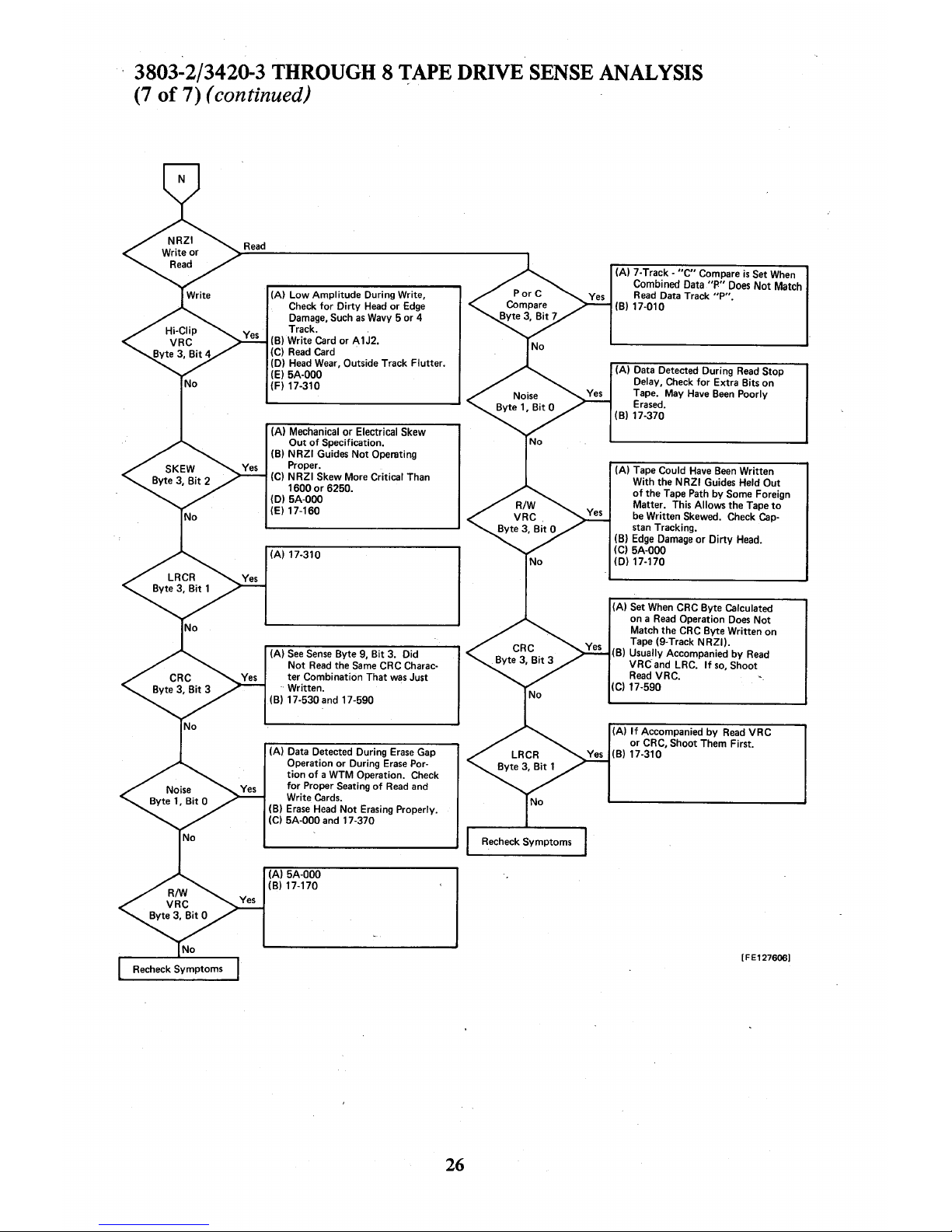
3803-2/3420-3
THROUGH 8 TAPE
DRIVE
SENSE
ANALYSIS
(7
of
7) (continued) ,
(A)
Low
Amplitude
During Write,
Check
for
Dirty
Head
or
Edge
Damage, Such
as
Wavy 5
or
4
Track.
(B) Write Card
or
A1J2.
(C)
Read
Card
(D)
Head
Wear, Outside Track Flutter.
(E)
5A-000
(F) 17-310
(A)
Mechanical
or
Electrical Skew
Out
of
Specification.
(B)
NRZI
Guides
Not
Operating
Proper.
(C)
NRZI
Skew More Critical Than
1600
or
6250.
(D)
5A-OOD
(E) 17-160
(A) 17-310
(A)
See
Sense
Byte 9,
Bit
3. Did
Not
Read
the
Same
CRC Charac-
ter Combination That
was
Just
Written.
(B)
17-530 and 17-590
(A) Data Detected During
Erase
Gap
Operation
or
During
Erase
Por-
tion
of
a WTM Operation. Check
for
Proper Seating
of
Read
and
Write Cards.
(B)
Erase
Head
Not
Erasing Properly.
(C)
5A-000 and 17-370
(A) 5A-000
(B) 17-170
26
(A) 7-Track -
"C"
Compare
is
Set
When
Combined Data
"P"
Does
Not
Match
Read
Data Track
"P".
(B) 17-010
(A) Data Detected During
Read
Stop
Delay, Check
for
Extra Bits
on
Tape. May
Have
Been
Poorly
Erased.
(B)
17-370
(A) Tape Could
Have
Been
Written
With the
NRZI
Guides Held
Out
of
the Tape Path by Some Foreign
Matter. This Allows the Tape
to
be
Written Skewed. Check
Cap-
stan Tracking.
(B)
Edge
Damage
or
Dirty
Head.
(C)
5A-OOD
(D) 17-170
(A) Set
When
CRC Byte Calculated
on a
Read
Operation
Does
Not
Match
the
CRC Byte Written
on
Tape (9·Track
NRZI).
(B) Usually Accompanied
by
Read
VRC
and LRC.
If
so,
Shoot
Read
VRC.
(C)
17-590
(A)
If
Accompanied
by
Read
VRC
or
CRC, Shoot Them First.
(B)
17-310
[FE127606]
Page 31

3420/3803 ONLINE TESTS
IBM
3420/3803 Online Tests, Listed
by
Section
Section
Test Focus
Test Mode
Test
TYEe
A:
CMD
Sequence Analysis
Control Unit
PE/6250/NRZI
Diagnostic
B:
Control Unit
Control Unit
PE/6250/NRZI
Functional
C:
Control Unit
Control Unit
PE and 6250
Functional
D:
Channel Buffer R/W & Mode Set Control Unit
6250/1600/NRZI
Functional
E:
Basic
Read and Write
Subsystem
PE/6250/NRZI
Functional
F:
6250 Data Path Verify
Control Unit 6250 Only
Functional
G:
6250 Error Detect/Correct
Control Unit 6250 Only
Functional
H:
PE Diagnostic Mode (Part 1)
Control Unit
PE Only Functional
I: PE Diagnostic Mode (Part 2)
Control Unit PE Only
Functional
J:
PE Diagnostic Mode (Part 3)
Control Unit PE Only Functional
K:
PE Diagno,stic Mode (part 4)
Control Unit PE Only Functional
L: Mod 4, 6, 8 Clip Level Check
Tape Unit PE Only Functional
M:
NRZI Control Unit
Control Unit
NRZIOnly
Functional
N:
NRZI Diagnostic Mode (Part
1)
Control Unit NRZIOnly Functional
0:
NRZIDiagnostic Mode (Part 2)
Control Unit
NRZIOnly Functional
P:
7 -Track Functional Tests
Tape
Unit NRZIOnly Functional
Q;
Long Record Write/RDB/Read Subsystem
PE/6250/NRZI
Functional
R:
Write Reliability
Subsystem
PE/6250/NRZI
Reliability
RO:
MAPs
Analysis
Control Unit 3803-2 Analysis
S:
Read Reliability
Subsystem
PE/6250/NRZI
Reliability
T:
Tach Parameters
Tape
Unit
PE/6250/NRZI
Diagnostic
U:
Tach Asymmetry
Tape
Unit
Pp/6250/NRZI
Diagnostic
V:
Start/Stop
Tape
Unit
PE/6250/NRZI
Functional
W:
IBG and Creep
Tape Unit
PE/6250/NRZI
Functional
WR:
MAPs
Analysis Control Unit
3803-2
Analysis
X:
Reel Response
Tape
Unit
PE/6250/NRZI
Functional
Y:
Data Access Measure 1
Tape
Unit
PE/NRZI
Functional
Z:
Data Access Measure 2
Tape
Unit
PE/6250
Functional
AB:
Device Switching
Control Unit
PE/6250/NRZI
Functional
AC:
Control Unit Status
Control Unit
PE/6250/NRZI
Functional
AD:
2-Channel Switch (Part 1)
Control Unit
PE/6250/NRZI
Functional
AE:
2-Channel Switch (part 2)
Control Unit
PE/6250/NRZI
Functional
AF:
2-Channel Switch (Part 3)
Control Unit
PE/6250/NRZI
Functional
AG:
2-Channel Switch (part 4)
Control Unit
PE/6250/NRZI
Functional
BA:
Stress Tape 1
Control Unit 6250 Only Diagnostic
BB:
Stress Tape 2
Control Unit 6250 Only Diagnostic
27
Page 32

3420/3803 ONLINE TESTS (continued)
Section RO-WR: Error Analysis
These two
OLTs apply
to
the 3803-2 only. The MAPs and the OLTs are designed as
an
integrated package. You should start with
the
MAPs
and
run
the OLTs
as
indicated when
analyzing an error.
All
of
the
3803-3420 OLTs diagnostics can
save
the
error sense data for later analysis
by
OLT 3420RO and OLT 3420WR. The error sense data "save" field
is:
a common area for
all
of
the 3803-3420 OLTs. Therefore,
if
more
than
one OLT is
run
and has errors, the
sense data from the last error in the last
OLT
run
is
available for analysis.
Although the sense data
is
saved for an error in all
of
the OLTs, only OLTs A-G, P, Q, R,
and
S are recommended for
FRU
analysis. The sense data from the other OLTs can be
analyzed,
but
the results may be misleading. This
is
due
to
errors
that
are forced
by
the
OLTs.
OLT
WR
has an EXT= option whereby sense data
to
be analyzed can be entered from
the keyboard.
Example:
DEV j3420WRjEXT= ,SNS=804400
8000002C000008000000C7j
At least the first fourteen bytes (0-13) should be entered. The extent field (EXT=) however, will
not
permit entry
of
all
24
bytes.
How
to
Generate a 'Prewritten' or 'Read Only' Tape
In MAPs,
you
will note references to a 'Read Only' tape. (In several sections
of
the User's
Guide,
you
will note references
to
a 'prewritten tape'. The terms 'prewritten' and 'read
only' are synonymous.) This tape
is
a diagnostic
tool
which should be generated when
the system
is
operating correctly. You should have a 'Read Only' tape generated in 6250
bpi available for analyzing failures. Sense switch Z which
is
in OLTs routines
A-G
gener-
ates 'Read
Only' data in
6250
bpi.
Note: When changing the EXT= parameter, the program must always be called:
Example: DEVj3420A-GjEXT=Zj
Example: j3420A-ZjEXT=WZj
not
j jEXT=Zj.
28
Page 33

3420/3803
ONLINE
TESTS
(continued)
To
generate a 'Read Only' tape (6250 bpi), the OLTs
A-G
are run with first error option
and sense switch
Z on.
Example: DEVj3420A-GjFE,EXT=Zj.
When
the 'Read Only' tape has been generated without any errors, the tape should be
file
protected.
False
Crease Tape Error -
OLT-
OLT
T3420I
T3420L
T3420K
T3420M
Messages
AIOI08
AI0137
AKOI06
AMOI08
If
byte
17
(EC)
is
not plugged correctly
on
logic AA004.
Prior
to EC733843 bit 6 and 7 should be
01
After EC733843 bit 6 and 7 should be 10
After EC734866 bit 6 and 7 should be
11
R060 OLTs reversed test I and
M.
If
byte
17
is
plugged incorrectly the wrong routine will be run.
o This
is
for a 3803
ModOOl
only. A 3803 Mod002 will be plugged for bit 6 and 7 = 01.
Stress Tape PjN1848621
A prewritten tape used for diagnosing the operating parameters
of
the 3803
Mod
2 has been
been generated by a unique machine for this purpose and cannot be created or duplicated
by any other known method. This tape
is
used in conjunction with OLT diagnostic
T3420BA and T3420BB (stress tape 1 and stress tape 2) and should be ordered from the
nearest
EPC
just prior
to
converting a 3803
Modell
to
a Model 2. Reference OLT User's
Guide dated March 1974 or later for explanation
of
tests etc. After the tape has been
used
to
check out the converted units the tape
is
to
be returned
to
its original stocking
location for use
by
other conversion sites. The tape
is
not intended
to
be kept
at
the
branch office or customer location. The reason for this
is
that there are only a limited
number
of
these tapes available.
As
recertification
of
the stressed data
is
not possible,
care must be exercised
so
as
not
to
damage the tape. A damaged tape will have
to
be re-
placed with a new one.
The recommended stocking level
is
three tapes
at
each emergency parts center (EPC).
29
Page 34

Page 35

WHAT IS WHERE
IN
THE
MLM?
MLMVolume 1
Section
PLAN
00
IA-6A
IB-6B
Contents
Safety information; table
of
contents (organization
of
publication), a list
of
abbreviations and symbols and the address for ordering the OLTs
User's
Guide.
Notes on how
to
use the
MAPs
effectively; training requirements for using
the
MAPs
effectively, method
of
identifying
ECs
which affect the MAPs,
standard plus and minus voltage levels encountered
;in
the machines,
sense byte chart with references to descriptions, a symptom index (page
0-010) for normal entry into the MAPs, a quick index (page 0-009) for
entry into the
MAPs
when you have one
of
the symptoms listed there
and you know whether the problem is in the
TU or TCU.
MAPs
for 3420 Models 3, 5, and 7 attached to 3803-2. (Same
as
Path-
finder for these models attached
to
3803-1.)
MAPs
for 3420 Models 4, 6, and 8. Note that Section I B follows Section
6A,not
IA.
Sections 1 through 6
(both
A and
B)
contain
MAPs
for TU power supply,
thread/load, basic motion, unload, read/write and capstan motion control
problems, in that order.
31
Page 36

WHAT IS WHERE
IN
THE
MLM?
(continued)
:MLM
Volume 2
Section
7
8
11
12
13
14
15
Contents
TV interface theory
Checks, adjustments, removals and replacements
Tev
power supply
MAPs
Procedures for duplicating failures offline and procedures for performing
various CE panel functions (extracting sense data, restart
on
ALV
error,
etc.)
MAP
procedures for
ALV
hangs or loops, channel busy, timeout, or other
indications where
the
microprogram does not appear
to
be looping nor-
mally (possibly also causing channel hang).
Manual analysis
of
sense data using a prioritized scheme.
MAP
procedures for miscellaneous errors.
32
Page 37

WHAT IS WHERE IN
THE
MLM?
(continued)
MLMVolume 3
Section
16
17
18
19
20
21
Contents
MAP
procedures for equipment checks
MAP
procedures for data checks, including timing charts
of
various data
operations plus second levels
of
the conditions required
to
produce
the
error.
Device switch theory and
MAPs
for problems isolated
to
the device switch.
Board layouts for the
TCU and TU boards showing
the
functions perform-
ed for each card to assist in card swapping.
Logic net cross-reference list. The MAP scoping procedures allow
you
to
identify a failing line and the
FRU
from which this line originates.
If
replacing
that
FRU
does
not
correct
the
problem,
you
may suspect a load-
ing problem
at
the
other
end
of
the
line (net). This cross-reference list
provides the references
to
logic for all line (net) names encountered in
the
MAPs
so
that
you
may more easily pursue problems
of
this nature.
OLTEP error message analysis. Used as directed
by
sense analysis sections
3420RO and
WR
after certain errors encountered
by
sections 3420 F and
G.
33
Page 38

WHAT IS WHERE
IN
THE
MLM?
(continued)
MLM
Volume 4
Section
40
50
52
53
54
55
57
58
75
80
85
90
Index
Contents
Subsystem characteristics, features, etc.
TCV data flow, MPI/MP2 schematic, ROSI trap conditions 6250 read/
write service requirements.
Microprocessor theory
TCV oscillators, clocks, counters and controls, second levels and theory
TV
selection and priority
Loop write
to
read (LWR) purpose, operation and data flow
NRZI data flow and theory
Two-channel switch and device switch theory
CE
panel-
description
of
switches and indicators
Tools and test equipment
Subsystem preventive maintenance
Subsystem installation procedures
34
Page 39

COMMON
ABENDS
Reference
MLM
00-035
Abends-
Theory
Abend
137,237,413,613,
and 637 may be caused
by
missing tape marks.
Missing
tape marks are caused by:
• Incorrect forward-backward ratio.
•
Loss
of
signal amplitude causing a failure
to
recognize the tape mark.
• Excessive crosstalk, indicating
that
data
is
fed into a dead zone. Data recorded on any
track in a dead zone. will prevent reading a tape mark correctly.
To
check for loss
of
amplitude and crosstalk
use
the failing drive and tape. Find the tape-
mark on the tape that
was
not read correctly. Cycle back and forth across the failing tape
mark with the
CE
panel. Sync on Go Forward (T-AIF2J10) and scope all tracks (read
card test points) and ensure that the signal
is
good on all tracks in zones 1 and 2 (tracks
P,
0, 5, and
2,6,
7).
Measure the amplitude on tracks 1, 3, and 4 (zone 3) and ensure that there
is
less than
140
mv
of
signal (Models 4, 6, and 8 only).
Crosstalk
is
caused by:
• Defective write
card.
• Defective read card.
• Defective R/W head.
• Poor tracking.
If
tracking
is
out
of
specifications
go
to
Capstan Dynamic Alignment
(see
08-150). The drive that wrote or read the tape, or both, could cause crosstalk.
If
the failing tape
is
not available, write a tape on a working tape drive offline, and use
that tape
to
check for crosstalk on the suspected failing drive.
137/637 Abend
Machine
Possible
Causes
Type
3803
Defective
01
A-A2N2
card
,
3803
Defective
01
A-B2F2
35
Page 40

COMMON
ABENDS
(continued)
237 Abend
Machine
Possible Causes
Type
3420
Large tape creases detected
as
gaps (check
stubby
bar clearance).
3420
Short
records (80 characters) falling within a
tape
crease.
3420
Tape edge damage.
3420
E/C
443935
(6250) - Fix for
short
gap verification
during backspace after a write error caused by
erratic
tape
motion,
not
installed.
3420
R/W
head forward-to-backward ratio
is
out
of
specifications.
3420
Tape sticking.
3420
Dirty capstan.
3803
Missing Suppress
Out,
intermittently breaking
channel/command word
(CCW)
chain, updating
the
count
but
not
losing a record.
3803
Defective
01
A-B3F2 inbound tag card XC700.
3803
ECA079 - Unexpected interrupt with status
=
'00'
from a non-two channel switch
in
multiple
CPU
2X, 3X, 4X, installation.
36
Page 41

COMMON
ABENDS
(continued)
413 Abend
Machine
Type
Possible
Causes
3420 Defective
T-A 1 C2
MST card.
3420
Reading 6250 tape in
1600 mode.
E/C 443890 -
Autocleaner sluggish,
not
installed.
3420 Defective
A1
H2
3420
. Defective
T-A
1 L2
3420 E/C 735817 -
Delay Ready after rewind,
Models
to
allow autocleaner
to
return,
is
not
installed.
4,6,8
3420
Damaged
tape
at
load point.
3420
Contamination on the Read/Write head, or the
capstan
is
glazed.
3803 Defective
01
A-A2D2 MST card or defective
01A-A2E2
MST card.
3803
Broken
CCW
chain
without
Unit
Check. Run
an
I/O software trace
for
more problem definition.
3803 ECA079 - Prevent busy in
middle
of
CCW
chain,
not
installed.
3803
ROS
patch
to
ALU1
for
allocated busy
is
not installed.
37
Page 42

COMMON
ABENDS
(continued)
613 Abend
Machine
Possible Causes
Type
3420
E/C
443935 -Short
gap engineering change
not
,.
installed.
3420
ECA073 - Delay Ready after rewind
to
allow
Models
autocleaner
to
return,
is
not
installed.
4,6,8
3420
Contaminated Read/Write head.
3420
Damaged
tape
at
or
near load
point
3420
Read/Write head forward-to-backward ratio
not
in
specifications.
3803
Defective
01
A-A2N2 card, extra
tape
mark.
Defective
3168/2880
card, high-speed buffer
~
data compare.
OS/VS2
PTF 70751
not
installed.
R017
3803-1
Tape Tracking, leaves a faint
TM
(where
existing files are updated) because
of
the
overwriting
of
the
old EOF TM.
In
this
case
the
writeheads actually
do
the
erasing
of
the
old TM.
3803-1 Defective
01
A-B2F2
3803
Incorrect
UCW
Plugging
Compatibility problems between drives can be caused
by
tracking out
of
adjustment,
or
if
this adjustment
is
OK, the tracks are
not
centered
on
tape. Develop tape and
place
it
on
the viewerto observe. The proper positioning
of
the head
to
tape relation-
ship
is
done
by
the Skew Plate. A special Skew Plate adjusting tool is necessary
to
do
this {included in the Reference
Plate replacement kit,
BM
4298806 stocked at the
(EPC's) E level parts centers}. Reference SA 9 and SA 10.
38
Page 43

TOOLS
AND
TEST
EQUIPMENT
The tools and test equipment listed
in
this section are required
to
properly service 3420
Magnetic Tape Units and 3803 Tape Controls.
Kept
at
the Regional Office
Part Name
8216729 ROS Address Tracer
8218343 Variable Frequency Oscillator
(VFO)
Kept
at
the Branch Office
Part
451064
453522
453585
4169639
2515376
2515390
2515401
2523723
5861448
5861455
5861452
8215414
Name
Master
Signal Level Tape (see Notes 1 and 4)
Degausser (see Note 1)
Developing Solution
*Digtec
251
Meter (Digitec
201
Meter, PIN 453046, may be used
if
it is available)
Scale, 0
to
6 pounds (belt adjustment)
Capstan Prealignment Gauge
Capstan Adjustment Wrench (rear adjustments)
Reel Motor and Hub Adjustment Tools (see
08-460)
Capstan
Adjustment Wrench (front adjustments)
7-Track NRZI Threshold Adjustment
Card
PE Threshold Adjustment Card
Dual Density Threshold Adjustment Card
ROS Patch Card
(see Note 1)
Kept at
EPCs
Part
4298806
1848621
Name
Reference/Skew
Plate Replacement Tool Kit (Ref
SA-9
and SA-l 0)
6250
BPI
Stress Tape (see Note
3)
*Trademark
of
United Systems Corporation
39
Page 44

TOOLS AND TEST EQUIPMENT (continued)
Kept
at
the Customer's Account
Part
8493001
352465
453500
453504
453522
1765342
1846251
1846252
2515745
2513154
2501611
2512063
2515390
Notes:
Name
Tape Transport
Cleaner
Scratch Tape
Oscilloscope (Model 453, 454, 561, 545, 766H or equivalent)
Tape
Cleaning Kit
Master
Skew Tape (see Notes 1 and 4)
Manometer 30 inch (two needed for series connection) (See Notes 1
and 2)
Tee and Hose Assembly (see Note 2)
Tape Development Solution
Tape
Unit Tester
Shim, Right Reel Hub Adjustment
Hex Wrench, Right Reel Hub
Adapter Hose (see Note 2)
Pressure Divider (see Note 2)
Tape
Unit Cleaning Brush
Crimper (supplied by marketing representative)
Capstan
Box.
Wrench (rear adjusting capstan only)
1.
Discussed in more detail in the
MLM
2. Not needed
if
pressure/vacuum gauge PIN 5495384 is available
3. 1848621 stress tape used for model conversions stocked at
EPCs.
See
Also see page 29 for description.
4.
Order through IRD per the "Order Processing" section
of
the IRD Branch
Office Manual.
40
Page 45

TOOLS AND TEST EQUIPMENT
(continued)
Master
Tapes
Master skew tapes and master signal-level tapes are manufactured
to
rigid specifications.
They are the standards that are used
by
CEs
to
obtain optimum tape unit performance.
Because tape unit performance
is
directly affected
by
the accuracy
of
these master tapes,
the following precautions should be
taken~
1,
Use
master tapes only for their intended purpose.
2. Handle tapes with care.
3. Make only full-reel passes in order
to
have even wear throughout the length
of
the tape.
4. Identify master tapes
as
such and mark the reels with the letter
"m,"
as
a reminder
to
make full passes only.
Master
Skew
Tapes
Master skew tapes have a density
of
800 fci and are written with one solid bit across the
width
of
the tape. These tapes are written
on
a specially adapted tape unit at the Tape
Test
Center with accuracy held
to
within 0.375 usec total skew between the leading and
lagging bits
of
a 112 ips tape unit.
The master skew tape will run
off
the reel when reading forward because it
is
written
with no interblock gaps (IBGs). In order
to
create an IBG and
save
time during skew
adjustments, make the follOwing alterations
to
the master skew tape:
1. Read the master skew tape forward
to
the end
of
tape (EOT) reflective marker.
2. Install a write enable ring.
3. Write one record
of
any size beyond the EOT marker.
4. Remove the
wr~te
enable ring.
5. Rewind the tape.
After the preceding one-time preparatory steps, set the tape control
CE
panel
as
follows
when you
use
the skew tape:
1.
Command I-Read Forward
('02')
2. Command 2-Read Backward
('~C')
3. Command 3-Read Forward
('02')
4. Command 4-Read Backward ('OC')
The master skew tape will read forward
to
the end
of
the reel, read backward, and repeat
the cycle. This permits checking skew from the rear
of
the tape unit without manipul-
ating the controls.
41
Page 46

TOOLS AND TEST EQUIPMENT
(continued)
Master
Signal-Level
Tapes
Master signal-level tapes have the ability
to
produce a signal to within
±2%
of
the primary
master. (A primary master, which
is
established
as
an
IBM
standard,
is
the base for in-
strument alignment.)
All
new master signal-level tapes are checked at 3200 fei and 800 fci. The suffix letter
"A"
is
added
to
the part number to allow field identification
of
3200/800/556 fei tapes
as
opposed
to
the former 800/556 fei tapes. Thus, for example, a master
Signal-level
tape
checked out at
both
3200 fei and 800 fei would have PIN 432152A.
Degausser
CAUTION:
Do
not
use
the degausser near magnetic tape
of
any kind because it erases
the information on tape. Power-down the tape unit.
To degauss the read/write head:
1.
Remove magnetic tape from the tape unit. Do not place the tape on top
of
the tape
unit.
2.
Plug degausser into 110 Vac receptable.
3. Press the pushbutton on the degausser while it
is
at least one foot (30,5 cm) away
from the read/write head and move it slowly toward the head.
4. Hold the degausser
agai~st
the front surface
of
the head for about ten seconds.
5. Pull the degausser straight away from the head very slowly
to
a distance
of
at least
one foot (30,5 cm) and release the pushbutton.
MST
Board Ordering
Instructions for ordering a 3803
MST
board for field replacement. The following infor-
mation must be supplied when placing the order.
1.
Machirie type and serial number
2. Features on the
3803
3. Part number
of
the
MST
board
4.
EC
level
of
the board
5. REAs installed (if any)
6. Board location (example -
B3)
7. Name and phone number
of
person to contact in case the plant needs further informa-
tion. Note: There are some
3803 boards with EC733806 written on the sticker. This
is
a non-existent
EC
number. The
EC
number should be EC733801.
42
Page 47

TOOLS
AND
TEST
EQUIPMENT
(continued)
8. Refer to AA005 in the logics for feature wiring before installing the board. (five pages
3803-2 and three pages 3803-1)
9.
Have
sufficient quantities
of
resistors
on
hand.
See
part numbers below.
3803
MST
Flat Cable Replacement - see General
CEM
251.
3420
MST
Flat Cables Replacement:
PIN
5802133 uses
PIN
580218048
in.
PIN
5802181 64 in.
PIN
5802134 uses
PIN
5802182
48
in.
PIN
5802183 64 in.
3803 Tie UplDown Resistors:
PIN
Wire
Color Resistance
2520936
2520942
Tie-Up
Blue
Tie-Down Yellow
51n
620n
43
Tie
to
Pin
D08
B06
Page 48

Page 49

MEDIA
Page 50

IRD
PEP
SPECIALIST
If
you have reason
to
believe the customer's tape library contains tapes
of
poor
quality or
if
you need expert assistance in finding methods
of
locating bad tapes then
consider contacting your IRD PEP Specialist.
The PEP (performance Evaluation Program) Specialist
is
a person expertly trained in all
phases
of
magnetic tape evaluation.
He
can provide assistance in most any area relating
to
media problems and should be a useful resource for the
CEo
Your field manager should be consulted before involving the PEP specialist.
45
Page 51

Page 52

MAGNETIC
TAPE
Most
of
the recording media in today's digital record environment
is
a polyethylene
terephthalate film, (mylar*), coated on one side with a flexible thin layer
of
ferro-mag-
netic material. The tape is slit
to
.498 ±
.002"
wide and reflective stickers are mounted
at each end
to
mark the beginning and end
of
the usable area
of
tape. Tapes come in
two standard lengths -
1200 and 2400 feet.
Under normal operating conditions tape should operate at least
40,000 passes before a
permanent read error is encountered. This
is
possible only when tape
is
stored in the
proper environment and handled properly when in use.
Tape can deteriorate due
to
conditions encountered
in
storage, handling, or operating
on
drives. This degradation will show up
as
an increasing number
of
temporary write or read
errors during its use until the damage gets extensive enough to cause a permanent error.
When storing tape
it
should be stored in an area where the temperature
is
between
40
degrees
to
90 degrees F
(4
degrees
to
32
degrees C) and 20 to
80
percent relative humidity (nominally 70 degrees F at 35 percent relative humidity). To operate, tape should
be at
60 degrees
to
90
degrees F (16 degrees to 32 degrees
C)
and 20
to
80 percent
relative humidity (nominally 75 degrees F at 45
to
50 percent relative humidity). When
tape
is
exposed
to
temperatures in excess
of
the above criteria degraded operations may
occur. Tape should be acclimated
to
the operating temperature for at least
24
hours
before use
if
large environmental changes are encountered in storage or use.
When
a reel
of
tape exceeds a specified number
of
errors it
is
recommended
the
tape be
removed from service. The specified number
will vary from customer
to
customer.
It
is
dependent
on
several parameters
of
this
total
system operation.
Details
of
tape properties essential for
IBM
tape units are found in
IBM
manual,
\GA32-0006, tape specifications for
IBM
one-half inch tape units
at:
556,800,1600,
and 6250 bpi.
*Trademark
of
E. L du Pont
de
Nemours & Co. (Inc)
47
Page 53

MAGNETIC
TAPE
(continued)
Tape
Quality
Reference GA32-0006, Tape Specifications for
IBM
One-Half Tape Units.
These paragraphs have been added
to
provide IBM's recommendations
as
to what quality
a tape should contain when new (paragraphs 1 and 2) and
as
it
exists in the library (para-
graph 3).
1. Sho_rt-Length Reliability
Definition - J'he ability
of
the tape
to
withstand the wearing action encountered
during repeated references
to
a short
file
of
data.
Recommendation - Under the conditions
of
the
follOwing
test procedure the tape
should average at least
40,000 read passes before a permanent error
is
encountered.
Procedure - Write a length
of
tape from load point with ten, 2000-character rec-
ords (PE recording).
No
write skips shall be allowed during the write pass. Then
read the ten records (read forward/rewind) repeatedly until a permanent read error
occurs. Perform this test with sufficient go-down time
(20.0 milliseconds)
to
en-
sure that the tape comes
to
a complete stop for each record.
2. Long-Length Durability
Definition - The ability
of
the tape
to
resist the wearing action encountered while
cycling full length
on
a tape unit. This
is
not a test for end
of
life.
48
Page 54

MAGNETIC TAPE
(continued)
Recommendation - At least 90 percent
of
the tapes tested should meet the follow-
ing criteria:
Tapes tested for use at
3200 fci should not average more than three write errors
per pass, or exceed ten write errors on any single pass, for a minimum
of
200 for-
ward passes on any
IBM
tape unit
that
operates at 3200 fci.
Procedure -
Use
the appropriate tape unit and associated tape control for this test.
Write a
2400-foot (732m) length
of
tape in start/stop mode with 2000-character
records (PE recording) on each pass. In order
to
determine the effect
of
wear part-
icles generated during the test do
not
clean the tape unit between passes.
3.
library
Quality
Definition - A measurement
of
the quality
of
tape
is
its write
ca
pabiltiy.
Recommendation - Tapes with more than twenty write skips are not recommended.
If
tapes
of
this type are used, more frequent cleaning
is
recommended.
Procedure -
Use
the appropriate tape unit and associated tape control for this test.
Write a
2400-foot (732m) length
of
tape in a start/stop mode with an average block
length
of
1.5 inches (38.1 mm).
By
use
of
Volume Error Statistics, a measure
of
the quality
of
the tapes and library can be determined. Volume Error Statistics are
available in the
IBM
Operating Systems, OS, DOS, and VS.
49
Page 55

Page 56

COMMON
MEDIA
RELATED
PROBLEMS
Unevenness
of
Tape
Wind
(Staggered
Wraps)
3420/3803 Service
Aid
4
The manner in which a tape stacks on a reel when rewound
is
a product
of
three factors:
The drive, the tape, and the reel. These all contribute: however, in an individual case, any
one
of
these may be predominant. Some items
that
are pertinent
to
this matter are:
1. Some irregularity
of
wind
is
to be expected.
It
is
caused by aerodynamics (escap-
ing
air forming a cushion between layers), and static electricity which will attract
or repel the tape
to
or from a flange in varying degrees
as
the tape
is
wound.
2. A perfectly smooth
wind (from a 3420 drive)
is
not necessarily desireable
as
it
tends to indicate the tape
is
being forced against one
of
the flanges or other guiding
surfaces.
3.
If
the wind
is
irregular, no damage
to
the tape will result unless poor handling
practices are followed; ie, pressure applied
to
the reel flanges causing a tape edge to
be
bent over. This may
be
due to improper stacking
of
multiple reels not in con-
tainers or cartridges designed to be stacked or squeezing the flanges while handling
or mounting a tape.
4. The flanges
of
the reel are not designed to guide the tape or help it wind smoothly.
The flanges are there only to protect the tape during shipping and handling, and
then only to protect it from something bumping the tape edges, not from pressures
of
such force
as
to
bend the flanges.
Devices can be developed which will wind the tape smooth.
You will note new tapes re-
ceived
by
customers have a smooth wind. The field situation does not warrant installing
and maintaining such a device on field drives.
With each complaint or concern
of
staggered wraps, the best approach
to
the problem
is
to
adjust the drives
as
accurately
as
possible,
so
they are not producing
~nnecessarily
poor winds. Inspect the drives for any possible condition that may indicate wear or interference in the tape path. After it has been determined that the mechanical alignment
of
the transport
is
acceptable, the customer should be instructed on proper handling
techniques for magnetic tape.
51
Page 57

COMMON
MEDIA
RELATED
PROBLEMS
(continued)
Z-Folds
Loose wraps are usually caused by poor handling or poor leader
on
tape. When
tape
is
loaded
on
machine the loose outer wraps are pulled tight against loose wraps further in
causing Z-fold.
Z-folds
can be avoided
by
adequate customer controls in tape handling, properly crimp-
ing end
of
tape, and library management. Also, beware
of
poor temperature control and
drives with different rewind tensions.
The
IRD
representative can provide a complete seminar which provides a comp-
rehensive approach
to
all areas
of
magnetic tape care and handling.
52
Page 58

3420
Page 59

READ/WRITE SERVICE TECHNIQUES
Temporary jPermanent Errors
The primary cause
of
write data checks
is
the type caused by a loss in signal from the tape
on readback during write.
On the 3420 tape subsystem when tape
is
written the ampli-
tUde\s checked
to
ensure there
is
sufficient amplitude written on tape
to
be read at a
later date. This write checking level (threshold)
is
higher than the threshold at which the
tapes will eventually be read.
If
the amplitude
of
the read signal goes below the threshold
a temporary write error occurs and the error recovery program (ERP) takes control.
ERP backs the tape up to the last gap, then performs an erase
gap
before retrying the
write operation.
If
the write
is
then error-free one temporary write error
is
logged and
normal operation continues.
If
the retried write operation again fails another erase
gap
then write
is
performed. This
is
continued until the write
is
successful or until fourteen
tries to write the record have occurred.
In
that event one loop write-to-read command
is
tried.
If
successful, one more erase gap, write
is
attempted.
If
it again fails (fifteenth
time) a permanent write error
is
posted (the temporary write errors associated with this
failure are then discarded).
If
the write command
is
successful on, for instance, try number 10 EREP would show
nine erase gaps (actual number)
but
only one temporary write error. The reason for this
is
that write errors occurring while ERP has control are not logged
to
EREP while
all
erase
gaps
are.
Several causes
of
data check on tapes are:
1. Defects in oxide on tape
2. Dirty tape
3. Dirty tape path
4.
Edge
damage on tape
5.
Contamination on head
6. Tape device failures
When
excessive
e~rors
are encountered on a tape, corrective action should be taken. The
first action
would be to inspect the tape path for contamination.
If
any foreign material
is
present,
it
should be removed by using normal cleaning procedures.
If
error persists the
tape should be tried on a second tape device (if available) or a different, known good, tape
should be put
on
the failing tape unit. In this way the error condition can be isolated
to
the tape or
to
the tape unit.
When
a tape with large numbers
of
errors
is
found in a cus-
tomer library it should be identified and corrective action
by
customer should be taken.
This can include cleaning and recertification
of
the tape or removing the tape from the
tape library.
If
a tape shows signs
of
damage or contamination it should be removed be-
fore it can cause damage
to,
or cause contamination
to,
other tape in the customer's
library.
There are many other types
of
errors and causes
of
errors. The several covered in the
above text are the most common causes and are the majority
of
the types
of
errors the
CE
will encounter in the. field.
S3
Page 60

3420
READ/WRITE SERVICE TECHNIQUES (continued)
Read Amplitude Adjustment (Amp Sensors)
.Read amplitudes are adjusted prior to shipment. They should normally be readjusted
only
if
the read/write head or the read card
is
replaced. Before performing the adjust-
ment procedure:
(MLM
ref 08-310, 46-8, or 08-290, 3-5-7)
1. Ensure that the
-4V
dc and
+6
V dc supplies are correctly adjusted before adjust-
ing the read amplitudes.
(See 08-570,
DC
Power Supply Checks/Adjustments.)
2.
Clean the read/write head and tape path before making adjustments.
Tape Slipping
Tape slip usually occurs during dynamic reversal while performing an erase gap com-
mand. Tape slip causes the tape to be incorrectly positioned.
When
the write head
becomes active it then erases part
of
the previous record. (The record before the
error record that the erase gap command
was
supposed to erase.)
Developing the tape shows the postamble missing on the previous record. For details
see
Tape Developing Procedure in 3420/3803 Reference Guide.
~IIIIIIIIIIIIIIIIIIIIIIIIILr
l
FEraSedGap
!lllllllllllllllllllllllllllllllllllf
t I J t t
Load
Point
Itl
Erased
Record
L-
Erased Postamble and Part
of
Data
on
Good Record
Possible Causes
of
Tape Slip:
a. Loss
of
capstan vacuum on Model 8
b. Drag in the tape path.
c. Dirty air bearings.
d. Low air pressure.
e. High or low vacuum.
f. Door
glass
leakage.
g.
Damaged capstan surface.
h. Possible media problem.
Note: Refer
to
3420 Tape Motion section
as
well for tape slip problems.
54
Page 61

3420
READ/WRITE SERVICE TECHNIQUES
(continued)
Noise or Bits in the Interblock Gap
To
detect interblock gap errors, sync scope
on -Go
Forward. Read forward and backward over the failing record. Display the record in both directions and look for noise
in the gap (see diagrams on
MLM
SA-lIS and SB-02S). Developing the tape with noise
in the interblock
gap
shows bits written in the area between two records (sometimes
faintly recorded).
Record
~
~1~IIOOIIIlIlIlIIIIlIlI~1I1I1
.,
Load Point
Possible Causes:
Record
t
I
~IIIIIIIIIIIIIIIIIIIIIIIIIIIIIIII~IIIIIIIIIII
t
Faint Line Approximately
.050,
(1.3 mm)
After
End
of
Record.
a. Gaussed or magnetized read/write head.
b. Erase head not working.
Bit
Packing
Record
t
1~llllllt
Bit packing
is
due to varying capstan speed or tape slipping. For scoping procedure
see
MLM
SA-lIS or SB-02S.
Also
see
3420 Tape Motion Service Techniques.
Possible Causes
of
Bit Packing:
a. Tape slip when written (glazed capstan).
b. Dented capstan.
c. Vacuum and air pressure
out
of
specification.
d.
Plugged air bearing.
e'.
Improper operation
of
digital
to
analog converter (DAC).
f. Defective capstan control board.
g.
Binds in capstan motor.
55
Page 62

3420
READ/WRITE SERVICE TECHNIQUES (continued)
Tape Edge Damage
Scope the outside tracks
(4
and 5
on
9-track drives) or (P and 7
on
7 -track drives)
on
the failing record. Look at the amplitude changes.
Developing the tape will show bits
that
were recorded on the tape and the tape was
damaged after it
was
written. This type
of
damage
is
usually caused
by
improper tape
handling.
Example: The tape reel has uneven wraps and the sides
of
the reel are squeezed
creasing the tape.
Read Forward
to
Backward Ratio Test (Models 3,
S,
7)
Use
this test
to
determine
if
a read/write head needs replacement.
Verify
that
the tape is tracking correctly before any head replacement because
of
the
above criteria.
Perform Field Tester Accuracy Check on 08-290 before proceeding.
1. Degauss the head (08-280) and the cleaner blade (08-390).
2.
Obtain a customer good quality representative tape and write
it
at 1600 bpi
on
the unit being checked. Write it from the field tester with frequency switch set
to
32.
3. Read forward
to
the middle
of
the reel
of
tape and stop tape.
4. Set the Field tester
as
follows.
ALTDIR
SLOW
READ
UP/FWD DN/BKWD.
Potentiometers all the way
to
the back
of
tester.
(Adjust DN/BKWD so tape has a forward creep rather than a backward
creep).
5.
Sync and scope the Read card test points to determine the fwd
to
bkwd ratio.
Display three or four cycles
of
read signal and use
as
much
of
the scope display
as
possible for measurements (.2v/cm). For ease
of
recording, scope J2B13 with
another probe, this line will
go
positive when reading backwards.
6.
If
there
is
a read backward problem, and the amplitude in the backward direction
is
less than
that
of
the forward direction
by
50% on
anyone
track, or 60% on the
remaining tracks, the read/write head should be replaced.
If
head replacement
is
required, perform the removal/replacement procedure on 08-250.
S6
Page 63

3420
READ/WRITE SERVICE TECHNIQUES (continued)
Read Forward/Backward Ratio Test (Tape Unit Models 4, 6, and 8)
Use
this test
to
determine
if
a read/write head needs replacement:
Verify that the tape
is
tracking correctly before any head replacement because
of
the
above criteria.
Perform Field Accuracy check on 08-315 before proceeding.
1.
Degauss the head (08-280) and the cleaner blade (08-390).
2.
Install a jumper from K2P02-M2D06. This forces 6250 mode.
3.
Obtain a customer good quality representative tape and write
it
at
6250 pbi on
the unit being checked. Write
it
from the field tester with the frequency switch
set at 64.
4. Read forward to the middle
of
the tape and remove jumper K2P02-M2D06 while
tape is moving, then stop tape.
5.
Set the Field tester
as
follows.
ALT DIRE
SLOW
READ
UP/FWD DN/BKWD Potentiometers all the way to the back
of
tester.
(Adjust DN/BKWD
so
tape has a forward creep rather than a backward creep).
6. Sync and scope the Read card test points to determine the fwd
to
bkwd ratio.
Display three
Dr
four cycles
of
read signal and use
as
much
of
the scope display
as
possible for measurements (.2v/cm). For ease or recording, scope H2M08 with
another probe, this line will
go
negative when reading backwards.
7. If there is a read backward problem, and the amplitude in one direction
is
more
than double the amplitude in the opposite direction on
anyone
track, replace the
read/write head.
If
read/write head replacement
is
required, perform the removal/
replacement procedure on
08-250, do required adjustments and return
to
the map
that sent you here or
00-030.
If
replacement
is
not
required return
to
the map
that
sent you here or 00-030.
Note:
If
while making measurements, the tape gets back
to
load point, (resetting the
6250 latch) the jumper K2P02-M2D06 will have to be reinstalled while at load
point and the tape read forward. This keeps the tape unit in
6250 without
forcing a
SAGC
setup on every record. Remove the jumper and continue the
test.
Each time the jumper is removed the
SAGC
may set up at a different ratio,
but
the ratio
will remain the same.
57
Page 64

3420 READ/WRITE
~ERVICE
TECHNIQUES
(continued)
Phase Shift
Definition - A pulse time displacement that occurs
at
the transition from a low density
recorded signal to a higher density, or from a high density signal to a lower density.
When
recording at higher densities several problems are encountered.
As
density in-
creases the preceding and following bits (flux fields) tend
to
interfere with the middle
bit (see Figure 1). This phenomenon
is
known
as
phase shift. The resultant data trans-
ition at a change in recording density
is
shifted
to
the right or left because
of
the bit
crowding effect. This characteristic
of
PE recording
is
compensated for by detection
techniques.
"
,
\
\
\
x
Figure 1
\ /
, "
o
'0
x x
2X
2X
Shift
58
Page 65

3420 READ/WRITE SERVICE TECHNIQUES
(continued)
Phase Shift Scoping Procedure
If
you are having a high number
of
temporary write errors with
MTE
and not ENV
errors, use the following procedure
to
determine
if
the R/W head
is
causing phase
Using
a good customer tape:
1. Check the
SAGC
setup. Refer
to
the
MLM
page 5B-000 sequence 1.2 and 2A
with Figure A on page 5B-001. The
SAGC
should set up in 2
to
14 steps.
2. Loop write reliability test 3420R in 6250 mode.
Scope the phase pointers:
CD191
CD291
CD391
Card
YIM2
YIL2
YIK2
Pins
GI2,J11,112
G12, J11, 112
GI2,J11,JI2
Zone 1
Zone 2
Zone 3
Sync Points: Crosspoint cards can be used
so
that only data from the drive you are
running
OLTs on
is
displayed (ie, logic XC701 drive 0 A3Q2
DI2).
Refer to Chart L
for your machine configuration.
If
you have the entire subsystem, sync point (mark 1)
logic
BW151
Al
G3
M12 may
be
used.
If
any phase pointer goes active, in the data area, the head
is
marginal. This procedure
is
intended to find new heads"that may be marginal
but
should be used
as
a check for
existing heads. Refer to
MLM
08-250 for additional information.
Compatibility
Compatibility problems between drives can be caused
by
tracking
out
of
adjustment,
or
if
this adjustment
is
OK, the tracks are not centered on tape. Develop tape and
place it on the viewer
to
observe. The proper positioning
of
the head
to
tape relation-
ship
is
done by the Skew Plate. A special Skew Plate adjusting tool
is
necessary
to
do
this (included in the Reference Plate replacement kit,
BM
4298806 stocked
at
EPCs.
Refer
to
SA-9
and SA-l 0).
S9
Page 66

Page 67

READ/WRITE FAILURE ANALYSIS
The purpose
of
this procedure is
to
provide an effective way
to
determine what R/W
component is failing. The procedure is comprised
of
three major sections. Initial
checks, failure analysis and
FRU
replacement. This procedure should help
you
reduce
the number
of
components replaced before fixing
the
machine.
Initial
Checks
Check
and adjust as necessary
the
following:
•
-4
and +6 volts (see 08-570)
•
Vacuum and pressure (see
08-400,08-405)
• Tape
path
obstructions
Check
the
following components for wear
or
oxide buildup.
- Erase head
- Filler block
-
Auto
cleaner
- Tape
path
area
• Clean
the
head
• Read head card
and
write head card seating
Failure Analysis
• Sense Data -Sense can be obtained from the following areas:
- EREP
Console messages
-
OLTs
The sense data can be analyzed using
the
sense analysis flowchart
in
this manual.
• OLTs - Tests
A-W
should be run using a good test tape.
If
no
failures occur use
the
customer's failing tape, also
try
another tape drive.
• Scoping - The following items should be scoped
to
determine failing components.
Stability -
Scope the analog signals
on
each track, the amplitudes should
be
con-
stant and
about
equal between tracks.
Forward
to
Backward Ratio - The analog signal amplitude
in
any
track
while read-
ing backward should
not
be
less
than
50%
of
the
signal amplitude reading forward.
_
Only replace the head
if
experiencing read backward problems.
61
Page 68

READ/WRITE FAILURE ANALYSIS
(continued)
SAGe -
All
tracks should set up between 2 and 14 steps and the tracks should set
up within 3 steps
of
each other. Replace the head only
if
the track setting up wrong
is
causing errors.
Phase Errors - Phase errors are indicated by
MTE
errors without envelope checks.
Scoping
is
done in the 3803 while writing ripple data with a block length
of
2K
or larger. This procedure
is
for model 4, 6, or 8 only. Refer
to
the phase shift
scoping procedure in this manual for complete details.
Tracking
Check - Using the master skew tape scope the 4 and 5-tracks. The signals
should be equal and opposite between forward and backward. For example
if
track
4 leads track 5
by
one usec in the forward direction, track 4 should lag track 5 in
the backward direction. Note: This
is
a check.
Do
not use for adjustment. (See
MLM
08-150, 08-151, 08-160.)
Bit Positioning - Improper bit positioning can be caused by an improperly adjusted
skew plate. Failures can appear
as
system abends and tape mark recognition problems.
Replacing the R/W head
will
appear
to
fix the problem for a very short time. Note:
Reference plate tool kit required. Refer to
SA
9 and
SA
10.
FRU
Replacement/Swapping
The following
FRUs are listed in the recommended replacement or swapping sequence.
If
a part does not fix the drives symptom, return the swapped part
to
the original drive.
•
MST
Logic Cards
•
Read Head Card
•
Write Head Card - Check
to
ensure that the write head card jumpering
is
correct.
• Read/Write Head -
When
a new head
is
installed for diagnostic purposes, only the
AMP
sensors need
to
be adjusted.
If
the head resolves the problem make certain
the Read/Write Adjustment procedures in the
MLM
(see 08-250) are followed.
62
Page 69

READ/WRITE HEAD SERVICE HINTS
Factors
that
may indicate a failing head:
1.
Media
2.
System aborts indicating read or write failures
Tape runs
off
end
of
reel searching for a tape mark
No
block detected
on
a write or write tape mark
3. . High temporary write errors
4.
High forward
to
backward analog signal ratio
5. Many
OLT failures on test T3420F and very few errors on other tests
6. Varying analog signals
7. Making two amp sensor adjustments
of
.5
volts or greater in a short period
of
time
Factors
that
may indicate a failing head when the head
is
not failing:
1.
Low vacuum
2. Tape hitting obstructions in the tape path
Erase head
Filler block
Rewind plunger
(3,5,
7)
Auto cleaner
3. Defective read or write head cards
4. Voltages
out
of
adjustment
5.
Poor tracking causing tape
to
buckle
6. Marginal media
7 . Visual wear and poor forward to backward ratio
Replace only
if
failures are occurring
Factors
that
optimize head life:
1. Good tape library maintenance
2.
Proper and timely drive cleaning
3. Documenting problems
4. Good capstan tracking
5 . Replace the head last
63
Page 70

Page 71

3420
READ/WRITE NTF CHECKLIST
If
you have an intermittent read or write problem and can find nothing wrong with the
machine, perform the tests/checks indicated below before writing a
"No Trouble Found"
IR.
When
completing an NTF IR, try
to
give
information
as
accurately
as
possible.
Use
Major Unit Code 960 instead
of
980 whenever possible and include
as
much detail
as
necessary in the narrative. Your IRs are the performance feedback mechanism
we
use on the 3420/3803!
Read/Write Problems
Models 3, 5, 7
Most
probable causes:
1.
Read head card defective
2.
Write
head card defective
3. T-AIL2, T-A112, T-AtM2
(NRZI}'tlefective
4.
R/W
head defective
5. Erase head defective
Initial checks:
1.
Air
pressure and vacuum (see 08-400)
2.
-4
Vdc and +6 Vdc supply in tolerance (see 08-570)
3. R/W head and cleaner blade must be clean
4. Capstan tachometer timing (see
08-130)
5.
Degauss tape transport
if
problem
is
recurring
Reference
MLM
5A-000
Models
4,
6, 8
Most probable causes:
1.
Read head card defective
2. Write head card defective
3. T-AIL2, T-AIJ2, T-AIH2 cards defective
4. R/W head defective
5. Erase head defective
65
Page 72

3420
READ/WRITE
NTF
CHECKLIST
(continued)
Initial checks:
1.
Air
pressure and vacuum (see
08400)
2.
-4
Vdc and
+6
Vdc power supplies in tolerance (see 08-570)
3.
R/W
head and cleaner blade must be clean (see Note 4 on SB-001)
4. Capstan tachometer timing (see 08-120)
5.
Degauss
tape transport if problem
is
recurring
Reference
MLM
SB-OOO
66
Page 73

TAPE
DEVELOPING
PROCEDURE
Purpose:
Gives
CE
a way
of
visually examining information recorded
on
a section
of
magnetic tape.
Materials Needed:
• Developing solution (P/N 453522)
Procedure:
• "Low-tack" transparent tape (See Note 1.)
• Piece
of
clear plastic (such
as
old microfiche card, loose-leaf
page cover , etc)
• Felt-tip pen
• Flat surface (small table, etc) which can be moved
to
area in front
of
tape unit
• Lint-free cloth (P/N 2108930) dampened with water
• Mount failing tape, without cartridge, and read to error. This
is
done
from 3803
CE
panel (offline) or using "FRIEND" (OLT T0200A) or
customer utility such
as
"ditto,"
etc (online).
•
When
failure occurs press reset on drive and open front door.
While
holding "cartridge-present"
button
pressed, manually
bottom
tape in
right column. This shuts
off
pneumatics.
• Open vacuum door and put small mark
on
bottom
(non-oxide) side
of
tape
on
each side
of
R/W head with a felt-tip marker.
• Carefully remove enough tape
to
reach the flat surface table, etc.
• Shake the developing solution,
then
immerse
the
affected area
of
the
magnetic tape into solution.
Use
the felt-tip pen mark
to
determine
suspect area. Rock tape back and forth two or three times being
careful
not
to
drag
on
bottom
of
can.
• Remove tape from solution and allow liquid to evaporate while still
rocking tape gently back and forth.
• Lay tape, oxide up, on the flat surface and use a small piece
of
trans-
parent tape at each end
of
developed area to hold in place.
• Tear
off
an appropriate length
of
transparent tape and carefully press
it onto the developed tape. Try
to
avoid air bubbles, etc.
• Gently lift the transparent tape back
off
(peel it at an angle
to
avoid
damage) and
phice
on
the clear plastic.
• The plastic with developed image may now be viewed directly or
under the microfiche viewer. Since the microfiche viewer magnifies
X30 be sure
to
divide any measured 'distance
by
30.
67
Page 74

TAPE DEVELOPING PROCEDURE
(continued)
• Clean the magnetic tape thoroughly using the cloth dampened with
water. Allow
it
to
air dry before rewinding and returning tape
to
cus-
tomer for his cleaning procedure .
.
CAUTIO~:
Any foreign material left
on
the tape
will
damage
the
drives themselves.
Conclusions:
Some
of
the more common problems which will be detected
by
tape devel-
oping are:
a. Partially erased records before an ERG. Usually caused
by
a glazed
capstan.
b. Noise in gap (defective erase head, etc).
c.
Short gaps (indication
of
tape motion problem)
d. Damaged tape (oxide voids, etc).
See
the following examples.
Note 1: The use
of
any other than "low-tack" transparent tape is discouraged as
it
may
remove oxide or leave adhesive
on
tape.
68
Page 75

DEVELOPED TAPE SAMPLES
Here are some tips which may be helpful in analyzing the failure
on
a developed tape:
• Distance Relationships:
~
.15"
1.18"----
..
• Erase Gap (ERG) Distances:
Density
6250
1600
800
7-Track
• Interblock Gap Size:
Density
6250
1600
800
7-Track
Developed Tape Examples
~
!--
__
To
BOT
t
Data
Block
Single
Successive
ERG
ERGs
3.75"
3.45"
4.2"
3.6"
4.2"
3.6"
4.5"
3.75"
Nominal Minimum
(Inches) (Inches)
.3
--
.6 .5
.6 .5
.75
.68
Good Data
at
1600 bpi
~.6"~
Good
Gap
69
Page 76

DEVELOPED
TAPE
SAMPLES
(continued)
Good Data at 6250 bpi
.3"
Good
Gap
To
.....
~~-BOT
Tape cinch/tape crease (1600 bpi)
caused
by
loose wraps
on
tape
reel.
~.6"~
To
"""--BOT
Good
Gap
t
Area
A
ERG
Performed
• Drive was writing when "cinched" tape (small Z-folds) area appeared (area A).
• Prior
to
performing an erase gap
the
software tried
to
back tape up
to
last interblock
gap
but
stopped in creased area instead (thought
it
was the gap).
• From there a normal ERG command was executed and tape unit logged one temporary write error and continued normally.
.•
Since damaged area was not completely erased
by
erase gap a permanent read error
then occurred when tape
was
read.
70
Page 77

3420
RD/WR DATA
FLOW
~~~;
....
0
1
Tape
2
Unit
3
Connector
Interface
4
AIN4
Connector
5
6
7
Read
and
Write Data
Flow
Within 3420
-
Models
4,6,8
Only -
(See
MLM
58·100 For Details)
0
Read
3
Connector
Card
4
AIN3
5
6
Write
Data
Flow
AIK6
AIJ2
Read
Data
Flow
AIL2
71
Connector
AIN2
Connector
AIT3
R/W
Head
Pin
Layout
(Models
4,6,8
Only)
L
Mounting Plate
4
0
0 0
t=
0
6
0 0
0
§
0
0
0
0 0
t:o
0
1
0
0 0
a;
0
2
0
0 0
:r:
0
en
p 0 0
0
en
0
3
0
0 0 u
0
7
0
0
0
E
0
5
0 0
0
E
0
1=
0
0
0
0
0
0
0
0
0
0
0 0
0 0
0 0
0
0
Read
Section Wnte Section
4
6
0
1
2
P
3
7
5
Note:
The
center tap
J
is
the middle pin
on
eacli track.
Tape
Unit
Interface
Connector
Page 78

3420
RD/WR
DATA
FLOW
(continued)
Tape
~~~~.....
~~~~face
Connector
,
Connector
AIN4
Read
Section
9 Track
AIK4
Write Section
Write
Data
Flow
AIK2
NRZI
Write
Deskew
(NRZI
Only)
AIJ2
The center tap
~
is
the middle pin
---
on
each
track.
Read
Pata Flow
~~~ectQr
1----4----------.;
AIL2
Read
and
Write
Data Flow Within 3420
- Models 3, 5, 7 Only (See
MLM 5A·100
or
PF
5·100
for
Details.)
AIM2
NRZI
Read
Deskew
(NRZI
Only)
72
Connector
AITJ
7T
k
-rae
Mounting Plate
fOJ
2 0 0
3 0 0
4 0 0
5 0 0
6 0 0
7 0 0
Read Section
Connector
AIN2
~D'
~
~ : ~
~
~
0 0 0 4
(J) 0 0 9 5
o 0 0 0 6
E 0 0 0 7
~
WnteSectlon
Tape
Unit
Interface
Connector
To
3803
Page 79

3420
TAPE MOTION SERVICE TECHNIQUES
Consider performing the following tests
if
you are experiencing intermittent 3420
failures relating
to
tape motion. The symptoms should first
be
analyzed using
MLM/
Pathfinder. \
Some
of
the more common symptoms associated with these service techniques are:
Symptom
Tape
Slip
Partially Erased Records
Permanent R/W Errors
High No.
of
Temp
R/W
Errors
Dropping Ready
No
Tape Motion
Dumping Tape
Glazed
Capstan Cleaning
Possible Cause
Glazed Capstan I
Glazed Capstan Also
see
3420 R/W
Glazed
Capstan Service Techniques
Glazed
Capstan
Leaky Transfer
Valve
or Column Vacuum
Door
Open Capstan Motor Segment
Open Capstan
Motor Segment
This procedure
is
performed only
if
glaze cannot be removed by normal cleaning.
CAUTION: This procedure,
if
not done properly and with extreme care, can
shorten
the
life
of
(or damage) the capstan.
If
the capstan edges are
rounded or flat spots are created, tracking adjustments will not be
possible.
Verify
that
this procedure
is
necessary:
1. Perform
Capstan Cleaning-Normal Procedure (see 85-004
if
necessary).
2. Perform
T3420W OLT diagnostic test.
• Run OLT T3420W to determine the size
of
interblock gaps.
[0.301 inches
is
nominal for models 4/6/8 and 0.600 inches
in nominal for models 3/5/7.]
73
Page 80

3420
TAPE MOTION SERVICE TECHNIQUES
(continued)
3. Check diagnostic printouts for signs
of
variance.
• Gap sizes exceed limits specified in OLT.
If
the tape
is
varying,
the
glazed capstan cleaning procedure may be necessary.
Proceed as follows: (Refer to "Tape Slipping" under 3420 Read/Write
Service Techniques.)
a. Assemble an abrasive tool using
600 grit paper
IBM
PIN
460107 attached to
a six-inch steel rule with a double back adhesive tape such
as
3M
Y-9122* or
4282*. You may also use rubber cement or printer carriage tape glue.
b.
Remove
the
left threading channel. Place the steel rule with 600 grit paper
squarely
on
the capstan and
then
just break the glaze
on
the capstan with the
abrasive tool while rotating the capstan
by
hand.
The intent
is
not
to
remove the glaze with the tool
but
to
break through the
coating
to
allow the tape cleaning solution
to
soak under it.
c. Moisten
cotton
swabs with tape cleaner and scrub the capstan rubber
thoroughly, until the capstan attains a dull rubber finish.
d. Follow
up
with a lint-free cloth moistened with tape cleaner to remove all
traces
of
the
cotton
swab.
e.
Verify
the
effectiveness
of
your cleaning
by
repeating the T3420W OLT
test.
f. Repeat the cleaning operation only
if
step e shows IBG variance.
g.
Capstan dynamic alignment (trackip.g) must now be checked.
Capstan Motor Test
Unplug the capstan
motor
from the capstan board and measure across the two wires
going
to
the
motor
with an ohmmeter. Rotate the capstan slowly
by
hand while watch-
ing ohmmeter. The meter will deflect some
but
should never
go
to
an open condition
(open armature segment).
If
an open condition occurs the capstan motor should be re-
placed.
Note: In the pneumatics portion
of
the drive verify normal pressure and vacuum ad-
justments and checks per
MLM
08-400 before 'performing the following tests.
Column Vacuum Leakage Test
If
you suspect a column vacuum leak the following procedure
is
a good way
to
check
column vacuum level:
- Take drive offline and install tape motion tester.
*Trademark
of
the
3M
Company
74
Page 81

3420
TAPE MOTION SERVICE TECHNIQUES
(continued)
- With drive unloaded, disconnect tubing
to
L3
or R3 vacuum switch.
-
Use a "Tee"
(P/N 1767025) to insert vacuum gauge (P/N 5495384) in the line.
- Reconnect tubing
to
L3
or R3
then
load tape and read gauge. Vacuum level should
be:
Model
Vacuum
3,4,5,6
21±3"
7 27±3"
8 31±2"
-
Move
tape forward and verify
that
vacuum level remains within tolerance.
- Move tape backward and verify vacuum level.
-
If
vacuum levels read low
on
these tests, clean column-to-glass mating surfaces and
check column glass adjustment.
Cracked Pressure Hoses
When analyzing any problem relating
to
pneumatics check for cracked pressure hoses.
The hose between pump and filter should be closely examined.
If
a hose
is
found
to
be
cracked replace it. Do
not
cut the hose back because it will soon crack again.
Transfer Valve Leakage Test
1. Cover the stubby column ports
with
masking tape.
See
Figure 1. Do
not
let the
tape overlap the stubby bars.
2. Place an 8-inch piece
of
magnetic tape in
the
bottom
of
the
right vacuum column
to
prevent vacuum from entering
the
column.
3.
Cut a 12-inch piece
of
magnetic tape and lay it over the left reel tach just below
the
read/write head. Ensure that
the
tape loop
is
approximately in line
with
the
bottom
of
the
capstan. See Figure 1. Bypass
the
door interlock.
4.
With no tape
on
the
right reel, press LOAD REWIND.
If
the
tape strip
is
pulled into-
the
left column before load check occurs, there
is
sufficient leakage
to
cause inter-
mittent
problems and
the
transfer valve must
be
replaced. Repeat
the
test several
times
to
ensure
that
the
valve
is
bad.
5. Remove
the
masking tape from
the
stubby column ports and clean 'the area
thoroughly with a cloth dampened with tape cleaner. Remove
the
magnetic tape
from
the
right and left vacuum columns.
7S
Page 82

3420
TAPE
MOTION
SERVICE
TECHNIQUES
(continued)
6.
If 3420 Drops Ready:
, Analyze
Sense
or
Scope Error Latches
to
Find
Reason
Error
Description
Fiber Optic
Lamp
Failure
Tape
Bottom
or
Pull
Out
of
Left
Column*
Tape
Bottom
or
Pull
Out
of
Right
Column*
Reset
Button
or
Door Interlock
Air
Bearing
Pressure
or
Right
Reel
Hub Failure
OV
/UV
(Power
Check)
or
No
Cooling
Air
to
Capstan Board
Power-On
Reset
Safety Bail
Reset
NOTE
Drive
Error
Latches
Error
(See
Note)
Sense
Probable
FRUs
+
At
S07
(Note
Latched)
+
At
U02
Byte 7 •
Optic
Lamp
Bit
0 •
AlD2
Byte 7
Bit 1
• L4 Vac Switch
•
L3 Vac Switch
•
Left
Reel
Board
• Capstan Tach
+
At
U05 Byte 7 •
R4
Vac Switch
+
At
S03
+
At
S04
-
At
S02
+
At
M05
(Not
Latched)
Bit
2 • Right
Reel
Board
• Capstan Tach
Byte 7
•
Reset
Button
Bit 3 • Door
Inlk
Switch
•
TA1C2
•
AB3F2
•
AA2D2
Byte 7 • Leaking File
Bit 6 Hub
•
Air
Bearing or
Hub
Switch
Byte 18 • Check Voltages
Bit 0 •
Dirty
Filter
•
Defective
Cooling
Fan
• Check Cooling
Air
Sensor
• A1C2
•
A1H2
•
Fuse
Detect
Card
Models 3,5,7
+
At
E2B09
(Not
Latched)
Models 3,5,7
• A1C2
•
Al
E2
Models
4,6,8
+
At
D4B09
(Not
Latched)
Models
4,6,8
•
A1K2
•
A1D4
• Drive error latches
are
on
following
card:
*Vacuum
switches
are
high-failure items.
Mod
3,
5,
7 - H2
Mod
4, 6, 8 - M2
• Voltage Levels are:
+
is
- .85
-
is
-1.85
76
Further
Analysis Notes
See
Logic
FTl14
Go
To
3A-ll0
or
3B-ll0
Could
Be
Caused
By
OV
/UV
Detection
or
Capstan Board Cooling
Sensor.
See
Byte 18
Bit
0 Below.
Could
Be
Caused
By
Operator.
See
Logic
t-----------1
FTl14
Go
To
lA-OOO
or
1
B-OOO
If
A Solid Failure Tape
Will
Not
Dump
Into
Cols on Load.
These
Errors
Cause
Reel
Board
EPO
Relays
to
Drop (Loss
of
Motor
Control)'
Tape
Bottom
Will Then Drop Ready
See
Logic
These
Are Not Normal
FTl12
Drop Ready Conditions.
See
Logic
FT283
However,
Intermittent
Failure May Show
as
a
Drop Ready.
Page 83

3420 TAPE MOTION
NTF
CHECKLIST
Perform these checks precisely
as
described in
MLM.
Check, adjust
if
necessary:
• BOT/EOT (08-580)
•
Capstan Tachometer Adjustment (08-120 or 08-130)
•
Pneumatics (08-400 [all] and
08420)
Reference
MLM
START 1.
77
Page 84

Page 85

3420
TAPE MOTION
Pneumatic System
with
Thread Status Active
Pressure
Sensing Switch
Scope
Points
'Ground = Pressure
Good
-4vdc = Pressure
Bad
Air
Bearing Model
Reel
Latch
Pressu
re
t
Pressu
re
E2M03
E2J02
D4J02
pr"l
mp
From Cooling Distribution Box
79
File Protect
Indicate Switch
Automatic
Latch
Upper Restraint
(Cartridge
Pressure)
Lower Restraint
(Threading Chute)
Left
Threadi
ng
Channel (Upper)
Right Threading
Channel (Upper)
Cleaner Blade
Capstan
Motor
Right Threading
~~~
Channel (Lower)
Transfer
Valve Assembly
(Actuated
for
Threading)
Left
Reel
Hub
l~i~jiili~iiiiIil
Pressure
1::'::':::,:1
Vacuum
Model 8 Only
Vac Switch
Layout
is
Typical
But May
Not
Be
the
Same
on
Your
Machine
Vacuum
Columns
Column
Vacuum Switch
Scope Points
tor
Adjust-
ment
Model
8 Only
Ground = Tape Above Switch
-4vdc
= Tape Below Switch
L1
B2S02
R1
B2508
L2
B2S03
R2
B2U09
L3 B2U04
R3
B2S09
L4 C2P09
R4
C2M09
} Refer
to
MLM
08-450
Page 86

3420
TAPE MOTION
(continued)
Pneumatic System
with
Thread Status Inactive
Pressure
Sensing Switch
Scope Points
Ground
=
Pressure
Good
-4vdc = Pressu
re
Bad
Air
Bearing Model
Reel
Latch
Pressu
re
+
Pressu
re
E2M03
3,5,7
E2J02
D4J02
pr"lm
p
From Cooling
Distribution
Box
81
File Protect
Indicate Switch
tor
Adjustment
Model
8 Only
Automatic Latch
Upper Restraint
(Cartridge
Pressure)
Lower Restraint
(Threading Chute)
Left
Threadi
ng
Channel (Upper)
Right Threading
Channel (Upper)
Cleaner Blade
Capstan
Motor
Right Threading
'-----II~~
Channel (Lower)
IIIl!l!l!l!l!l!Il!l!1
Pressure
1::··1
Vacuum
Model 8 Only
Vac Switch
Layout
is
Typical
But
May
Not
Be
the
Same
on Your Machine
Column
Vacuum Switch
Scope Points
-----------------
Ground = Tape Above Switch
-4vdc
= Tape Below Switch
L1
B2S02
R1
B2S08
L2
B2S03
R2
B2U09
L3 B2U04
R3
B2S09
L4 C2P09
R4
C2M09
} Refer
to
MLM
08450
Page 87

3420
POWER SERVICE TECHNIQUES
• When checking
DC
voltages use all standard safety precautions.
The +6 Vdc should be adjusted with the
3420
in write status, ready, away from
load point, and moving tape.
3420
Power Check, No File
Protect
or
Power Related Problems
After using
the
MLM
without results
on
power
type
problems, the following list will
give
some
of
the known problems in this area. With power type problems it
is
a good
idea
to
go
over the supplies checking for loose screws, fuse holders, cable connectors,
etc. Check supply levels. Vibration may help aggravate failures.
1.
Bad connector
to
power resistor panel. Shows
on
LOAD.
2. Loose screws
on
transistors
on
power interface board.
-4V
low.
3. R 67
on
fuse detect card defective.
J6
cable shorted to frame.
4. Bad solder connections
to
fuses.
5. Power check air flow bit
on,
command status reject. Loose capacitor screws.
Slip
on
connector
to
power interface board solder connection bad or rivets
loose or dirty filter.
6. Power check light glows dim.
-4V
return screws loose.
7. Power check light flashes. Phasing bad or TPl-1-2-3100se.
8. Drops vacuum. Bad solder connection O/V
U/V reference card socket.
9. Power check, load check lights flicker.
K1
relay
on
reel board points
burn,
48V
supply drops. Loose
48V
wire from C8
to
HS1
on
mounting block for CR
11
12
or loose TBl-6-7.
10. Bad connection
on
J7 socket.
11. Power check
when
drive selected. Loose wire
on
power interface board where
wire comes through board
to
transistors.
12. Rewind unload in middle
of
job.
Short from
MSC
card
to
cover.
13. Heat sink 1
on
48V
supply has loose wire.
14. Bad power interface board. No
-4V.
15. Fails
to
write, dumps tape. Bad 6V supply, or bad connection
to
fuses
on
piggy
back supply.
16. Fails
on
write operation. Bad power interface board.
17. Equipment check unload in middle
of
job. Loose fuses
on
piggy back supply,
has ripple
on
supplies.
18. Blows fuse 6 and
CP
1. Bad SCR card, SCR1,
SCRll.
19. Select light after load. Flat cable from
11
on
reel board pinched and shorting be-
tween frame and power interface board.
20. Equipment check, power check light
on
dim. Bad monitor card.
21. Bad fuse detect and EPO card.
22. Blows fuse 3
on
piggy back supply. Bad write driver card.
23. Damages tape
on
rewind. Bad reel
motor
board.
83
Page 88

3420
POWER SERVICE TECHNIQUES
(continued)
24. Bad
CB
1, or loose screws on CB.
25. Defective diode board
in
4V
supply.
26. Frame ground at
-12
volts. Erase head shorted
to
frame.
27. Blows fuse
10 or 12. Loose screws
on
TB
5-1.
28. 6V high or has ripple, bad power interface board.
29. 6V varies or blows reg card, bad connection 17-7
to
17-8.
30. Reed relay on OV
/W
card.
31. Blows fuse 6,
MSC
card shorted
to
support bar.
32. Diode assembly
on
YB020.
33. F13 - PCB board.
34.
F12
- Write
PCB
board.
35.
F14
- Shorted write head card.
36. Blows write driver card and
F14.
Read write cable plugged one pin off.
37.
No
output
+ 12,
-12,
4V
or 6V. Shorted cap
Cll
on
XFMR.
38. Blows
OVjUV card. HS-l transistor
on
power interface board.
39. Load check light flashes -loose fuse 3 or F3 holder.
40. Lights flicker with vibration - suspect any fuse holder.
41.
Plus 6 volts ripple or varies
...
CRI9,
20, 21, 22
on
PC2.
42. Command reject
...
ribbon cable from
01 A Al
board smashed between frame and
pneumatics cover.
43. ID burst checks
...
loose capacitor screw in power
tub.
44. Power check, no
-4V
or +6V
output.
Transfer valve picked solid. (9XXXX series
drive) power interface board
PIN 2515544, bad solder connection at connector
number
10.
45. Intermittent channel errors (ALV hangs, ALV errors) or R/W error
count
high.
Scope 4 and 6 volt supplies for excessive ripple during failure
if
possible. Failures
are almost solid while there is ripple and
then
disappears when the ripple goes away.
84
Page 89

3420
POWER
NTF
CHECKLIST
• Check that air filter
is
clean and blower
is
running smoothly.
• Check/adjust
DC
voltages (watch for excessive ripple content).
• Check for loose power supply screws
if
problem
is
recurring.
85
Page 90

Page 91

3420
POWER -
DC
VOLTAGES
CAUTION:
Be
sure to
use
a digital voltmeter,
PINs
453046, 453585, or equivalent,
when making adjustments and use all safety precautions.
Notes:
1. Ensure that the tape unit
is
loaded, ready, and in write status before checking or
adjusting +6 V power supply. After check or adjustment, measure the voltage at
T-Al
G2Bl1.
If
voltage exceeds +6.24 V, check the file protect circuitry for
re-
sistance.
2. The maximum allowable ripple voltage
is
24
mv
peak-to-peak measured at the
power. supply.
Models 3, 5, and 7
If
you have an unmodified power supply, check voltages at
the
following test points.
Power Supply Value
Test Point
Ground
+6v
(±O.05v)(See Note 1
and
2)
T-A1G1 E09
T-A1G2D08
-4.05v
(±O.05v)(See Note
2)
T-A1 N3D02
T-A1N3D08
-48v
(+7v,
-9v)
TB1-9
TB1-8
+12v (±1v)
TB2-1
TB1-8
-12v
(±1v)
TB2-5
TB1-8
+11v (+2v,
-1.2v)
TB3-12 TB2-4
Basic Power Supply
87
Page 92

3420
POWER -DC
VOLTAGES
(continued)
If
you have a modified power supply, check voltages at the following test points.
Power Supply Value Test Point
Ground
+6v (±O.05v)(See Note 1
and
2)
T-A1G1E09 T-A1G2D08
+11v (+2v,
-1.2v)
TB2-1 TB2-4
-4.05v
(±O.05v)(See Note 2)
T-A1N3D02
T-A1N3D08
-48v
(+7v,
-9v)
TB1-9
TB1-8
+12v (+1v)
TB3-1 TB1-8
-12v
(±1v)
TB3-5 TB1-8
+30v (±O.5v) *
TB2-3 TB1-8
-12v
(±1v)*
TB2-2
TB1-8
+12v
(±1
v)
*
at
Fuse
7
TB1-8
*
Used
only
for
OV
/UV
sense.
Modified Power Supply
88
Page 93

3420
POWER -DC
VOLTAGES
(continued)
Models
4,
6, and 8
If
you have an unmodified power supply, check voltages at the following
points.
Power Supply Value
Test Point Ground
+6v
(±O.1v)(See Note 2)
T-A1G2B11 T-A1G2D08
-4.05v
(±O.05v)(See Note
2)
T-A1 H1C09 T-A1G2D08
-48v
(+9v,
-9.6v)
TB1-9 TB1-8
+12v (+1.4v,
-O.9v)
TB2-1 TB2-4
-12v
(±1.4v)
TB2-5 TB2-7
+11v (+1.7v,
-1.1v)
TB3-12 TB2-4
If
you have a modified power supply, check voltages at the following
points.
Power Supply Value
Test Point Ground
+6v
(±O.1
v)(See
Note 1 )
-T-A1G2B11
T-A1G2D08
+11v (+1.7v,
-1.1v)
TB2-1
TB2-4
-4.05v
(±O.05v)(See Note
2)
T-A1H1C09 T-A1G2D08
-48v
(+9v,
-9.6v)
TB1-9
TB1-8
+12v (+1.4v,
-O.9v)
TB3-1 TB3-4
- 1
2v
'(
± 1 . 1
v)
TB3-5 TB3-7
89
Page 94

Page 95

3420/6250 CONVERSION TIPS
The following are some hints for field conversion.
IMPORTANT:
•
Follow the instructions in the conversion books very carefully .
• The majority
of
problems
that
occur after conversion result from cards or cables
not
seated correctly and dirty,
bent,
or recessed pins.
Conversion Kits
Recommended actions prior
to
installing conversion kit.
A. General
1.
The
EC
check list
(3420
ECA 056)
It is
of
the utmost importance
that
the
EC
checklist be correct.
If
it
isn't,
you
will get the wrong parts. Do a physical check
of
each E/C
that
is
supposed
to
have been installed.
2. The prerequisite
EjCs
must be installed
on
the machine and the machine test-
ed prior
to
installing the conversion kit.
3. RPQ, features
If
features and/or RPQs were ordered for the
3803-1,3420-3,
5, 7
they
must be installed and operational before doing the conversion.
If
features and/or RPQs were ordered for the 3803-2 configuration,
they
must be installed after the conversion is complete and operational.
40
Recommend the use
of
a Circuit Test Probe Part 453587
to
expedite verifi-
cation
that
the adds and deletes are correct.
5. Ensure
that
you
are familiar with the conversion instructions before starting.
It
is
recommended
that
you
read
them
at least once prior
to
starting the con-
versions.
6. Review ITIPs (and data bank)
to
become aware
of
problems
that
may
be
en-
countered during conversion.
7. Prior to installing logic cards and connectors make sure there are no
broken
or bent pins. Inspect for recessed or loose pins on the data cable
connectors
(channel-to-tape control unit and tape control unit-to-tape unit).
91
Page 96

3420/6250
CONVERSION
TIPS
(continued)
8.
All
connectors and logic cards installed/replaced
as
called out in the conver-
sion should be
"popped"
(eg, seated, removed and re-seated) a few times
to
assure a good contact.
9. The installation
of
the tape cleaner does not eliminate the present head clean-
ing procedure. -
B.
Only the logic board and logic cards in the conversion kit have been tested on a
"slave machine"; cables and jumpers have not.
C.
Double check all card plugging
to
ensure that
they
reflect the converted status
of
the machine. The exception
is
on page 0950
of
the TU Conversion book. The
original model number
of
the TU should
be
plugged, not the new model that it
was
converted to.
D.
3420 Conversion Hints
After removing
"old"
fiber optics lamp, clean the ends
of
light pipes
in
the horse-
shoe with a damp, lint-free cloth. After power has been turned on, allow the
"new"
fiber optics lamp to warm up for 20-30 minutes.
1.
Assure that the R/W card cables are connected correctly.
It
is
possible to
miss the top pins
of
the R/W card connector.
2. Before removing the R/W cable guide, observe how it
is
mounted on cable
connector and reassemble it the same way when you have finished modifying
the cable.
3. Remove the coating on the R/W cable connector before soldering wires
to
it.
4.
When
the tape unit interface adapter shoes are installed correctly you should
see
the silver plating.
5.
Page
0490
of
the Tape Unit Conversion
book
is
causing some confusion. The
wires are connected to AEI and AE2 connectors which are located on the
small board (PN 4169370) on the side opposite to where the components are
mounted.
6. Assure that the vacuum column restrictors are installed properly.
7.
If
after the conversion you experience R/W problems check the auto cleaner
adjustment (page
1080). Also, assure
that
the auto cleaner
is
not
activated.
This can be checked visually
by
removing the cover
of
the R/W cards (on the
front
of
the machine). With the columns loaded and looking down towards
the head you should
see
part
of
the white ribbon used in the auto cleaner.
92
Page 97

3420/6250 CONVERSION
TIPS
(continued)
8. OLT
3420L
should be
run
using the same magnetic tape
that
you
used when
you
adjusted the amplitude.
Usted
below are the major conversion efforts
that
apply to all models:
1. Replace tachometer assembly and capstan control power board.
2. Replace R/W head.
3. Replace R/W cards.
4. Add new read cable.
5. Rework write cable.
6. Replace logic board.
7. Add six new
MST cards.
8. Add new power cable.
9. Remove high-speed rewind plunger.
10. Remove inspection mirror and lamp.
11. Add tape cleaner assembly.
12. Rework write-enable circuit.
13. Rework three logic cables.
14. Rework pneumatic distribution.
15. Rework or replace power supply.
16. Rework or replace power interface (miscellaneous) board.
If
converted
to
a Model 6 or 8:
1. Replace vacuum column glass with one
that
has a resonator.
The following additional rework
is
required for conversions to Model 8:
1.
Replace the capstan motor.
2. Replace the vacuum pump.
3. Rework the pneumatic supply
if
the
drive
motor
is
not in the middle.
4. Rework the transfer valve.
5. Replace the reel motors and boards
if
converting from Model 3 or 5.
6.'
Rework the power door
if
lower glass was
not
installed.
Conversion Tips from Data Bank
3420 Reference page 0453
of
Conversion Instructions.
Do
not
remove
the
"0"
ring
type washer, placed between reference
"B"
and
"F".
What should be removed
is
about
1"
- 1
*"
long and shaped like an
"L".
3420 Erratic high-speed rewind - check resistor and cover assembly part
PIN.
For
Model 6
PIN
1845820.
93
Page 98

3420/6250
CONVERSION TIPS
(continued)
3420 Conversion reel motor change - when replacing reel motors
of
different styles, a
cooling hose reducer
PIN
2513076 may be required,
as
well as different anti-
rotation screws
PIN
0438579 or
PIN
0438581.
3420
Tape crease after model change - capstan
to
stubby bar clearance
ora
pneumatic
pressure check for possible air leaks may need
to
be done.
3420 Offline tester conversion (6250), check
MLM
page 90-170.
3420
Fail
to
load, reels do not turn - booster supply board
PIN
2515544 defective.
3420 Velocity check after conversion from a Model 3 to Model 7 - resistors for
assembly
PIN
2523731 should be 1 Ohm, 1 Ohm, 2 Ohm. They were 2 Ohm,
2 Ohm, and 10 Ohm, even though the correct part number
was
stamped on the
assembly.
3420
No
read or write after conversion (to 6250). Open paddle land to AIN7D02 or
could be an open solenoid or cable.
3420 Various errors after model change - check ALD page A6106 for proper position-
ed jumpers (2 pages).
3420 Won't load (any model) reels won't turn, transfer
valve
or KI won't pick,
but
the pneumatic motor runs. Incorrectly connected cable
(El
and E2 connection)
to the piggy-back supply board attached
to
the booster supply.
Compatibility problems between drives can be caused by tracking out
of
adjustment, or
if
this adjustment
is
OK, the tracks are
not
centered on tape. Develop tape and place it
on the viewer
to
observe. The proper positioning
of
the head
to
tape relationship
is
done
by the Skew Plate. A special Skew Plate adjusting tool
is
necessary
to
do this (included
in the Reference Plate replacement kit,BM
4298806). Reference
SA
9 and
SA
10.
94
Page 99

3420
PM
SCHEDULE
Code
1--......-
Location
U
R
Operation Frequency
Action
0
Door Slide
4 months
Lubricate the door slide and the stop pin with
and
Stop
IBM
#17.,
Pin
General
4 months
1.
Clean front deck and base.
Cleaning
2. Remove tape cleaner block and clean with
tape cleaner.
3. Remove air bearing (D-bearing) next
to
EaT/BOT
block and clean. Inspect guide
behind bearing and replace
if
grooved.
4.
Clean NRZI guides.
5.
Clean
EaT/BOT
channel mirror.
6.
Clean the fiber optic lamp.
Use
a tissue
lightly moistened with water.
CAUTION:
Allow lamp
to
cool before
cleaning.
Remove the manifuld and fiber bundles
to
provide access to the lamp. Replace the lamp
(08-620)
if
it
is
not
clear. Note: Cleaning or
replacement
of
the fiber optic lamp requires
the readjustment
of
the
EaT/BOT
and capstan
squaring.
Capstan 4 months Check and adjust Capstan Squaring.
See 08-120
Tach
or
08-130. Ensure capstan
is
free from dents
Squaring
and does
not
bind.
Circuit
Capstan
4 months Check and adjust Capstan Tracking. See
Tracking
08-000.
EaT/BOT
4 months Check and adjust EaT/BOT. See 08-580.
95
Page 100

3420
PM
SCHEDULE
(continued)
Code
r--r--
Location
U
R
Operation Frequency Action
File
Protect 4 months
1. Push plunger in, check for binds.
Pin 2. Check that plunger extends in front
of
the
right hub flange.
3. Replace unit
if
any checks product unsatis-
factory results.
Power 4 months Check for the correct operation
of
the power
Window window safety bail.
If
incorrect, tighten the
Safety
Bail
setscrew in the safety bail terminator, and
adjust the safety bail switch assembly (see
08-000).
2
Parts 12 months Order one
of
the following
B/Ms
for required
Replace-
parts.
ment
-
B/M
8492273 Puralator type filter
-
B/M
8492274 Cuno type filter
Tape
12 months Replace the tape cleaner block. Supplied with
Cleaner
parts replacement B/M.
Block
Pneumatic 12 months Check pneumatic supply belts.
Supply Belts
Input 12 months Replace
filter element
of
the pressure pump
Filter input filter. Supplied with parts replacement
B/M.· Check for Puralator or Cuno type.
Cooling 12 months Clean cooling air filter or replace
as
necessary.
Filter
Air
12 months 1. Remove bearings.
Bearing
2. Brush each bearing
to
remove oxide deposits.
Cleaning 3. Install new decorative covers on air bearing.
Supplied with parts replacement
B/M.
4. Check pressure (see label).
DC
12 months Check the dc voltages. (08-570)
Voltage
96
 Loading...