

Page 1
GA26·1638-2 /
File No. 5370:07 ·
Systems
Reference Manual for
IBM 3350
Direct Access Storage
Page 2

Preface
This publication
cessing personnel with the characteristics of IBM
is
intended to familiarize
data
pro-
3350
Direct Access Storage. The reader should have prior
knowledge of direct-access storage devices and
concepts.
The publication lists the functional characteristics and
describes the record format, capacity, and timing
characteristics. A list
3350
is
included in the Channel Commands section.
of
all commands executed by the
Suggested operator instructions are included in the
Operator Controls and Indicators section.
The following publications are recommended for
detailed information
con<:;erning
the subjects covered
in this manual:
IBM
No.
GA22-
System/370
7000
•
• Reference Manual
Model
2,
Order No. GA26-1617
Principles
for
IBM
of
Operation, Order
3830
Storage Control
• Reference Manual for
Control, Order No.
IBM
Integrated Storage
GA26-1620
• The functional characteristics manual applicable to
Order
the parent system.
characteristics manuals can be found in the
System/
and System I 3
360
Bibliography, Order No.
70
Bibliography, Order No.
numbers for functional
IBM
GC20-0360
GC20-0001.
• The Data Processing Glossary,
Order
No.
GC201699, defines terms related to direct-access storage
devices.
• Additional information for use when planning a
3350
installation can
be
found in the
3350/
3344
Installation and Conversion Guide, Order No.
GC20-1780.
If
IBM 3350s are
part
of a system which includes the
IBM 3850 Mass Storage System, certain attachment
restrictions may apply. These restrictions are detailed
IBM
3850
MSS
in the
Principles
of
Operation,
Order No. GA32-0029.
Third Edition (April 1977)
This
publication replaces
IBM 3350 Direct Access Storage,
contents
edition.
change.
Changes
periodically made. Before using this publication in
of IBM
Copies of this
Offices.
A
form
This
Publishing,
©Copyright
ii
of
Changes
or
equipment,
form
for
has
been
manual
IBM
3350 Reference
Technical
additions
and
reader's
removed,
was
prepared
Department
International
and
makes
Order
Newsletter
or
additions
to the specifications
contact
other
comments
are
the local IBM
IBM publications
is
provided
send
your
by
the
G26, 5600 Cottle Road,
Business Machines
Manual
the
second
edition
No. GA26-1638-1, obsolete.
GN26-0326
indicated by a vertical
comments
IBM
contained
Branch
can
at
the
General
has
be
back of this publication. If
to
the address below.
Products Division, Technical
San
Corporation
of
Reference Manual
been
incorporated
bar
to
in this publication
connection
Office
for
revisions.
obtained
through
Jose,
California
1975, 1976, 1977.
The
into this
the left
with
the
IBM Branch
95193.
for
of
the
are
operation
the
Page 3
Contents
Introduction. . . . . . . . . . . . . . . . . . . . . . . . . . . . . . . . . 1
Highlights
General
IBM
Attachment
Compatibility With Existing Storage
IBM
IBM
IBM
Models and Special
3350
Special
String Switch
Primary
3350
Data
Data
Record
Count
Key
Data
Track
Home
Record
Data
Write Padding
Track
3330
3350
Input/Output
Drive
Drive Addresses . . . . . . . . . . . . . . . . . . . . . . . . . 15
Valid
Seek Addresses. . . . . . . . . . . . . . . . . . . . . . . . . .
Access
Seek Time . . . . . . . . . . . . . . . . . . . . . . . . . . . . . .
Head
Latency................................
Data
Data
Write
Seek Verification . . . . . . . . . . . . . . . . . . . . . . . . 18
File Protection . . . . . . . . . . . . . . . . . . . . . . . . . . 18
..................................
Description
3350
Attachment
3330
Model 1 Compatibility
3330
Model
3350
Native
Models
Head/Disk
Formats
Groups
Format
Capacity
Modes
Integrity
................................
Features
Controller
................................
................................
Format
Area
Area
................................
Area
................................
Address
Zero
Records
Compatibility
Native
Operations. . . . . . . . . . . . . . . . . . . . . 15
. . . . . . . . . . . . . . . . . . . . . . . . . . . . . . 15
3350
and
Data
Selection Time . . . . . . . . . . . . . . . . . . . . . 1 7
Transfer
Protect
..........................
........................
to
3850
System
11
Compatibility
Mode
Features
.............................
.............................
Adapter
Assembly
..............................
...............................
...............................
............................
..............................
.............................
...............................
. . . . . . . . . . . . . . . . . . . . . . . . . . . . 10
Modes.................
Mode
. . . . . . . . . . . . . . . . . . . . . . . 10
Addresses.....................
Transfer
Rate.
. . . . . . . . . . . . . . . . . . . . . . 1 7
and
Security. . . . . . . . . . . . . . . . . . . 18
. . . . . . . . . . . . . . . . . . . . . . . . . . . 18
..................
.............
Mode
........
Mode
.......
.....................
....................
..................
....................
Time . . . . . . . . . . . . . . . 17
10
15
1 7
1 7
17
6
6
6
6
7
Error Recovery . . . . . . . . . . . . . . . . . . . . . . . . . . . . 1 9
l
1
3
3
3
3
3
3
4
4
4
4
4
5
6
6
6
Error
Correction
Error
Correction
Error
Recovery
CCW
Restart
Error
Correction
Recovery
Channel Commands
Control
Search
Read
Sense
Format
Update
Sense
Sense Byte Summary. . . . . . . . . . . . . . . . . . . . . . . .
Sense Bytes
Commands.
Commands
Commands.
Commands
Write
Write
Data
Function
Table . . . . . . . . . . . . . . . . . . . . . . l 9
Action . . . . . . . . . . . . . . . . . . . . . . 19
Construction
Table. . . . . . . . . . . . . . . . . . . . 20
Action Table
.........................
. . . . . . . . . . . . . . . . . . . . . . . . . 25
. . . . . . . . . . . . . . . . . . . . . . . . . . 25
. . . . . . . . . . . . . . . . . . . . . . . . . . 25
Commands.
Commands
. . . . . . . . . . . . . . . . . . . . . . . . . . . . . . .
0-
7 Summary. . . . . . . . . . . . . . . . . . . . 32
. . . . . . . . . . . . . . . . . . . 19
. . . . . . . . . . . . . . . . 19
....................
. . . . . . . . . . . . . . . . . . . . . . . . 25
. . . . . . . . . . . . . . . . . . . 25
. . . . . . . . . . . . . . . . . . . . 25
21
25
31
31
6
6
6
Operator
Operator
Ready
Attention
Read,
Start/Stop
Power
Power
Enable
Power
A and B
Controller
Primary
Primary/
Index
Controls And Indicators . . . . . . . . . . . . . . 43
Panel . . . . . . . . . . . . . . . . . . . . . . . . . . . . 43
Lamp
. . . . . . . . . . . . . . . . . . . . . . . . . . . . 43
Pushbutton.
R/W
Switch . . . . . . . . . . . . . . . . . . . . . . . 43
Switch. . . . . . . . . . . . . . . . . . . . . . . . 43
Control
....................................
Panel
On
Switch . . . . . . . . . . . . . . . . . . . . . . . .
Power
On
Off
Indicator
Enable/Disable
Assignment Panel
I
Alternate
Alternate
. . . . . . . . . . . . . . . . . . . . 43
(A2/
A2F)
. . . . . . . . . . . . . . 44
Switch . . . . . . . . . . . . . . . . . . 44
. . . . . . . . . . . . . . . . . . . . . .
Switches . . . . . . . . . . .
(C2/C2F)
Switch . . . . . . . . . . . . . . . . .
Indicators
(C2/C2F)
. . . . . . . . 44
......
44
44
44
44
44
45
Contents
iii
Page 4
Illustrations
Figure
Figure 2.
Figure 3.
Figure 4.
Figure 5.
Figure 6.
Figure 7.
Figure 8.
Figure 9.
Figure
Figure 11.
Figure
Figure 13.
Figure 14.
Figure 15.
Figure 16.
Figure 17.
Figure 18.
Figure 19.
Figure 20.
Figure 21.
Figure
Figure 23.
Figure 24.
Figure 25.
Figure
Figure 27.
Figure 28.
Figure 29.
l.
10.
12.
22.
26.
IBM
3350
Disk Storage
Basic
3350
Characteristics
3350
Track
Format
Record
Record
Drive Addressing. . . . . . . . . . . . . . . . .
Addresses for
Mode
Addresses for
3330-11
Error
Recovery
Control
Search
Read
Sense
Format
Update
Sense Bytes 0
Sense Byte 0
Sense Byte
Sense Bytes 2
Sense Bytes 6
Format
Format l Summary
Format 4 Summary
Format 5 Summary
Format 6 Summary
3350
3350
3350
Capacities,
Capacities, With Keys . . . . . . 13
3330-1
. . . . . . . . . . . . . . . . . . . . . . . . . 16
3350
Compatibility
Correction
Action
Commands.
Commands.
Commands.
Commands
Write
Write
Messages. . . . . . . . . . . . . . . . .
Operator
Power
Controller
Table
Table
Commands
Commands
through 7 Summary
Description
l Description . . . . . . . . . .
through 5 Descriptions.
and
Panel.
Control
Assignment
.............
...........
.................
Without
Native
. . . . . . . . . . . . . .
. . . . . . . . . . . . . . . 27
. . . . . . . . . . . . . . . . 28
................
7 Descriptions . . . .
. . . . . . . . . . . . . . .
. . . . . . . . . . . . . . .
.......
. . . . . . . . . . . . . . .
Panel
Keys . . . .
Compatibility
or
Modes
. . . . . . . . . . . .
. . . . . . . . . . . .
. . . . . . . . . . . . . 43
......
. . . . . . . . . .
. . . . . . . . . .
. . .
. . . . . . . . . . 33
, . . . . . . . 41
. . . . . . . . .
Panel.
. .
2
5
8
11
15
16
20
21
26
29
30
30
32
34
35
36
37
38
40
42
44
44
iv
IBM
3350 Reference
Manual
Page 5
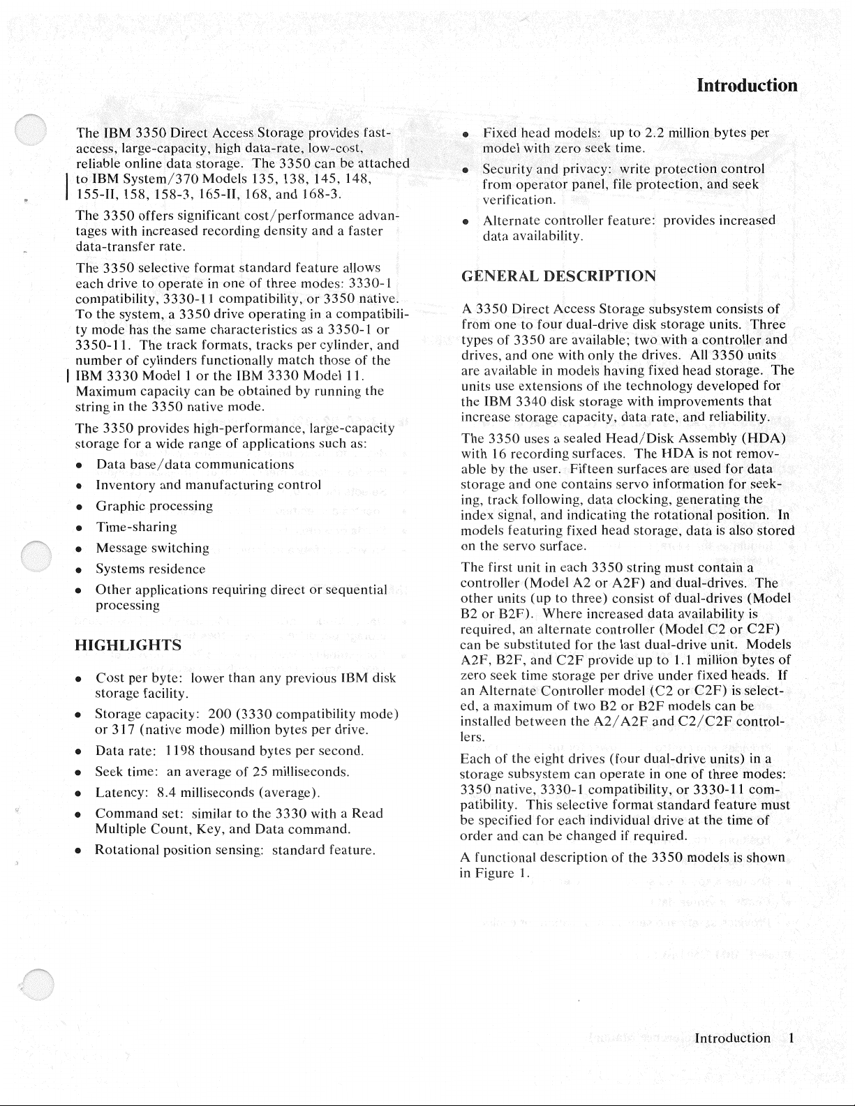
The
IBM
3350
Direct Access
access, large-capacity, high
data
reliable online
to
IBM
System/370
155-Il,
The
tages with
data-transfer
The
each
compatibility,
To
ty
3 3 50-1
number
I IBM
Maximum
string in
The
storage
•
•
•
•
• Message switching
• Systems residence
•
158,
3350
offers
increased
3350
selective
drive
to
the
system, a 3350
mode
has
the
1.
The
of
cylinders functionallv
3330
Model 1 or
capacity
the
3350
3350
provides
for a wide range
Data
base/
Inventory
Graphic
Time-sharing
Other
processing
processing
applications requiring direct
storage.
Models 135, 138, 145. 148,
158-3,
165-H, 168,
significant
recording
rate.
format
operate
3330-1
data
and
in
l compatibility,
same
characteristics
track
formats,
can
native mode.
high-performance,
communications
manufacturing
HIGHLIGHTS
•
Cost
per
byte: lower
storage
•
Storage
or
Data
•
• Seek time:
•
Latency:
•
Command
Multiple
•
Rotational
317
facility.
capacity:
(native
rate:
mode)
1198
an
average
8.4 milliseconds
set: similar to the
Count,
position sensing:
200
thousand
Key,
Storage
data-rate,
The
3350
and
cost/performance
density
standard
one
of
drive
operating
the IBM '3330
be
obtained
of
applications such as:
than
(3330
million
of
25 milliseconds.
and
feature
three
modes:
as a
tracks
per
match
by
control
any
previous IBM disk
compatibility
bytes
bytes
per
(average).
3330
Data
command.
standard
provides
low-cost, .
can
168-3.
and a faster
or
in a compatibili-
cylinder,
those
Model
running
large-capacity
or
per
second.
with a Read
fast-
be
attached
advan-
allows
3330-1
3350
native.
3350-1
sequential
feature.
of
11.
mode)
drive.
or
and
the
the
• Fixed
"'
•
GENERAL
A
3350
from
types
drives,
arc available in models
units use
the
increase
The
with 16
able
storage
ing,
index signal,
models
on
The
controller
other
B2
required, an
can be
A2F,
zero
an
Alternate
ed, a maximum
installed
lers.
Each
storage
3350
patibility. This selective
be specified for
order
A functional
in
Figure
head
model
with
Security
from
verification.
Alternate
data
one
IBM
3350
by
track
the
first unit in
or
seek
of
native,
and
operator
availability.
Direct Access
to
four
of
3350
and
one
extensions
3340
storage
uses a
recording
the user.
and
one
following,
and
featuring
servo surface.
(Model
units
(up
B2F).
alternate
substituted
B2F,
and
time
Controller
between
the eight drives
subsystem
3330-1
and
can
description
1.
models: up
zero
seek
privacy: write
panel, file
conlroller
DESCRIPTION
Storage
dual-drive disk
are available;
with
only
of
disk
storage
capacity,
sealed
surfaces.
Fifteen
contains
data
indicating the
fixed
each
3350
A2
or
to
three)
Where
increased
controller
for
C2F
provide
storage
of
two
the
A2/A2F
can
compatibility,
each
individual drive
be
changed
the
per
82
operate
to
2.2 million
time.
protection,
feature:
subsystem
two
the
drives. All
having
the
Head/Disk
head
fixed
technology
with
data
rate,
The
surfaces
servo
clocking,
storage,
string must
A2F)
and
consist
data
last
dual-drive
up
drive
model
(C2
or
B2F
and
(four
dual-drive units) in a
in
format
if required.
of
the
3350
Introduction
bytes
protection
provides
storage
with a
improvements
Assembly
HDA
are used
information
generating
rotational
dual-drives.
of
dual-drives
availability is
(Model
to
1.1
under
or
models
C2/C2F
one
or
standard
control
and
increased
consists
units.
controller
3350
head
storage.
developed
and
reliability.
is
not
position.
data
is
contain
C2
unit. Models
million
fixed
C2F)
can
of
three
3330-11
feature
at
the
models is
for
time
per
seek
Three
and
units
for
that
(HDA)
remov-
data
for
seek-
the
also
stored
a
The
(Model
or
C2F)
bytes
heads.
is select-
be
control-
modes:
com-
must
of
shown
of
The
In
of
If
Introduction
1
Page 6

3350-A2/A2F
IBM
3350-A2/A2F
drives)
CONTROLLER
C2/C2F,
• Interprets and executes
control
• Regulates the storage
interfaces
• Checks data
correction
can
(only
be
functions
one
online}
integrity
or
C2/C2F
controller
commands
control
by
error
(controller
in a string,
and disk drive
detection
from
and
A2/
the storage
3350-82/B2F
and two
A2F
or
error
IBM
3350-B2/B2F
e Responds
e Positions access mechanism
• Selects the read
locates a specified
•
• Reads
• Provides
or
writes
safety
to
(two drives)
commands
I
write
head
sector
data
and service
from
the
controller
at
a physical cylinder
on
a selected track
information
or
3350-C2/C2F
(shown)
for
evaluation
• Controls the
format
• Furnishes status and sense
control
• Performs
string
writing
fields
diagnostic
and
evaluation
• Serializes and deserializes data
• Provides and controls ac
string
(A2/
A2F
only)
DRIVES
• Responds
(A2/A2F,
to
or
C2/C2F
commands
from
• Positions access mechanism
• Selects the read I
•
locates a specified
• Reads
• Provides
Figure
or
writes
safety
I.
IBM 3350 Disk
write
head
sector
data
and service
Storage
interpretation
information
of
power
for
has
two
independent
the
controller
at
a physical
of
to
the
3350
the entire storage
cylinder
on a selected track
information
for
the track
the storage
storage
drives)
evaluation
IBM 3350-A2F,
• Native
storage
Compatibility
•
head storage
Mode
per
B2F,
- provides
drive
with
Mode
per
drive
and C2F Models
1,
144 kilobytes
zero seek time.
- provides 742 kilobytes
with
zero seek time.
of
fixed head
of
fixed
2 IBM 3350 Reference Manual
Page 7
IBM
3350
ATTACHMENT
The
3350
can
be
attached
System/370
Model Attachment Device
] 35
138
145
148
155-II
158*'
158-3
165-11
168,
168-3
*Also 158
Attachment
involve additional
Attachment to
The
3350
Storage
native
I
3850
staging. A
provides additional
3350
storage
Storage
staging
Expanded
feature
can
be
C2/C2F
Figure
systems:
3830-2
Integrated
3830-2
Integrated
3830-2
Integrated
submode! 2 (Japan
of
IBM
requirements.
IBM
DASD
System Staging
mode;
Control
adapters
on
made
in their normal
1.)
however,
to
be
control
either
up
of
can
new
microprogram
attached
and
on
store
the
Models
Storage
Storage
Storage
3350s
3850
be
attached
Adapters
the
feature,
to
the
either
is a
3830-3
configuration
to
the
following
Control
Control
Control
only)
to
the
systems
Mass
to
as real spindles in
3 3
50s
cannot
control
storage
to
IBM
158/
168 ISCs
one
or
both
prerequisite
or
ISC.
A2/
A2F,
(ISC)
or
3830-2
(ISC)
or
3830-2
(ISC)
or
3830-2
shown
may
Storage System
the
3850
Mass
be
used
for
store
additional,
to
permit
3830
Model
paths.
for
Each
B2/B2F,
sequence.
that
the
3350
3
have
new
string
and
(See
COMPATIBILITY
STORAGE
Each
3350
drive
is
formatted
of
three
operating
3330-11
modes
unit.
IBM
In
contains
logical
volume
IBM
In
one
3330-1
in
IBM
In
logical device with
bytes
compatibility,
can
vary
3330
the
3330-1
two
3330-1
in
capacity
3330
the
3330-11
logical
3330-11
l volume is
capacity
and
3350 Native
the
3350
of
storage.
modes:
between
Model
compatibility
logical
volume is
and
Model
compatibility
equal
format.
native
mode,
the
WITH
or
EXISTING
at
3330-1
3350
drives
manufacture
compatibility,
native.
on
the
1 Compatibility
mode,
a single
3330-1
11
volume
volumes
equal
to
an
format.
Compatibility
mode, a 3350
of
data.
to
an
actual
Mode
the
drive is used as a single
full
capacity
Operational
same
Mode
of
data.
actual
Mode
Eac,;h
3330-11
of
317
into
one
string
3350
drive
Each
3330-1
drive holds
logical
volume
,498 kilo-
or
Introduction
3
Page 8
Models and Special Features
The
3350
dual-drive storage units are available in six
and
can
models
described when required.
incorporate
3350MODELS
Six
3350
models are available: the
and
storage
with fixed
storage),
heads), the
controller),
heads
The
fixed heads
provide
storage
takes the place
the
moving heads.
When
3330-1 compatibility mode, the fixed
associated with the first
logical volumes
controller),
heads
the
C2
and
and
alternate
up
to
per
drive.
a Model
and
controller),
B2F
(dual-drive storage with fixed
(dual-drive storage
the
C2F
controller).
on
Models
1.144
million
The
of
an equal
A2F,
B2F,
on
the drive.
the special features
A2
the
A2F
(dual-drive storage
the
B2 (dual-drive
and
(dual-drive storage with fixed
A2F,
B2F,
bytes
of
zero
fixed
head
storage capacity
amount
or
of
the two logical 3330-1
C2F
of
drive
head
(dual-drive
alternate
and
C2F
seek time
storage
is
used in
storage
under
the
is
The
fixed
head
storage capacity
and
C2F
is:
3350
Native Mode Compatibility Mode
Logical Cylinders 1-2
Tracks
Tracks/Logical
Cylinder
Capacity
(bytes)
Capacity
(bytes)
SPECIAL
Three
Direct
and
String
/Drive
/Unit
FEATURES
special features are available for the IBM
Access Storage: string switch,
primary controller adapter.
Switch
0-29
30
1,144,140
2,288,288
of
Models
3330-1
0-18
742,710
1,485,420
remote
A2F,
or
1-3
19
B2F,
3330-11
3350
switch,
The
C2
and
C2F
alternate
the user to manually select
C2/C2F
drives
controller requires service, manual switching
other
A2/
subsystem availability
When
controller
reservations
procedures, required by
must be
Installation
a
3350
adapter
ler.
The
as
the
online controller.
then
function as a
controller
A2F
subsystem
performed
subsystem requires
feature be installed
basic
when
(by
a switch
control
to
the
other,
(if
any) are lost.
of
an
alternate
3350
characteristics are
by the user.
controller models permit
either
the
A2/
The
other
B2/B2F
preceded
on
the
to
be re-established.
has
outstanding
the
controller (
that
unit.
If
by a
power
C2/C2F)
been
Recovery/restart
controller switchover,
a primary controller
on
the
unit allows
switched from
status
C2
A2/
A2F
shown
A2F
the online
and
or
in Figure 2.
or
the
controller
to
the
off
on
the
one
drive
C2F)
control-
on
The
string switch feature, available
models, allows a
shared
dedicated
Enable/
be
(A2/
switch feature
mended
C2/C2F
storage control.
REMOTE SWITCH ATTACHMENT
The
switch
System/370
string switch feature is a prerequisite for this feature.
Primary
The
the
adapter
controller
through use
a
by
Disable switch.
installed
A2F
that
to
remote
to
be controlled from the
Controller Adapter
primary controller
A2/
A2F
permits
3350
subsystem.
3350
subsystem
two
storage controls.
to
a single storage
The
on
either
or
both
and
C2/C2F}
is
installed
a string switch also
allow communication with more
(Enable/Disable)
Model
when a C2/C2F
the
of
the
A2/
of
a manual switch
in a string.
on
158
or
168 Multiprocessor.
adapter
selection/
A2F
unit as
for
all controller
to
be
dynamically
The
3350
can
be
control
controller units
the
through use of
string switch feature
If
the string
A2/
A2F,
it is recom-
be
installed
switch allows the string
control
feature
model
is
deselection
the
online controller
on
the
on
than
panel
is
required
used.
of
the
C2/C2F
the
of
The
The
unit in
can
one
a
on
the
4 IBM
3350
Reference
Manual
Page 9
The
3350
storage subsystem uses a sealed,
assembly
(HDA)
as the storage medium.
ing heads and the carriage are
HDA.
an
integral
head/
The
part
disk
recordof
the
All
IBM
3350
drives are shipped formatted in the operating
3350
Head/Disk
mode specified by the customer.
operate
in a different mode it
can
an IBM supplied program.
If
an
HDA
be
reformatted
Assembly
is
to
with
Characteristic
3350
in
3330-1
Compatibility Mode
(2 per drive)
404
Cylinders per drive
Tracks per cylinder 19
Tracks per drive
Track capacity
(bytes)
Cylinder capacity
(bytes)
Drive capacity
(approx bytes) (per logical volume)
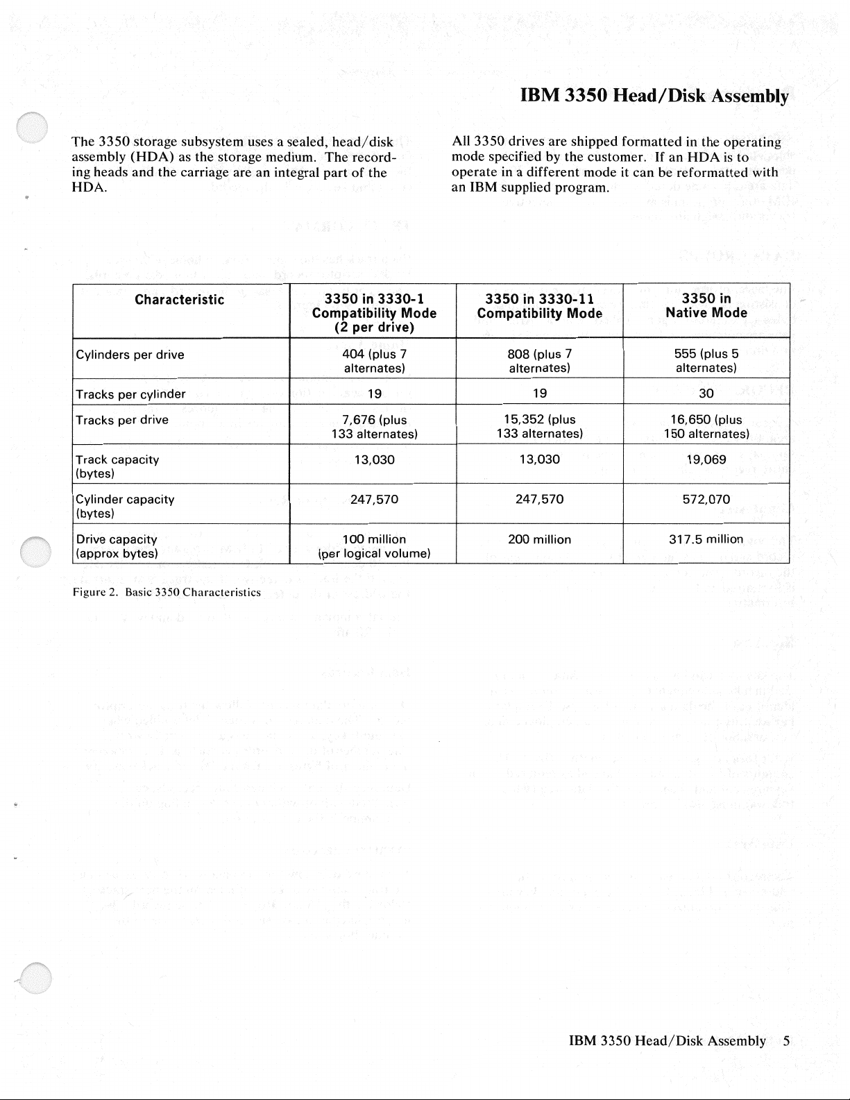
Figure
2.
Basic 3350
Characteristics
(plus 7
alternates)
7,676
133
alternates)
13,030
247,570
100
million
(plus
3350
in
3330-11
3350in
Compatibility Mode Native Mode
808
(plus 7
alternates)
19
15,352
133 alternates) 1 50 alternates)
13,030
247,570
200
million
(plus
555 (plus 5
alternates)
30
16,650
317.5
(plus
19,069
572,070
million
IBM
3350
Head/Disk
Assembly 5
Page 10
Data Formats
All
3350
drives are initialized
shipped with a home address and an eight-byte
descriptor
data
IBM utility program
tracks
record
areas become defective during normal use, an
and
assign alternates.
(RO)
is
written
available
at
manufacture
on
all tracks.
to
flag defective
If
and
track
the
The
data
area
length
Once
formatted,
the
data
area
count
and key areas in the record.
TRACK
FORMAT
can
the
be
is
defined
contents,
changed
by
the
count
area.
but
not
the length,
without affecting the
of
DATA
The
consisting
bytes
gaps are
tion unit.
RECORD
A record consists
area, the key area,
sary gaps to
entire record
GROUPS
basic information unit
of
eight bits
separated
combined
by
FORMAT
separate
is
called formatting.
Count Area
The
count
area
contains the physical address
record and defines
the record.
is
formatted
reformatted.
The
and
count
is
Key Area
stored
by the drive
(binary
a gap
to form a record, the basic informa-
of
three specific areas: the
and
the
them).
the
size
area
not
changed
digits). A group
is
called an area. Areas and
data
area (plus
The
process
of
key
and
data
is
written
until
when
the
is a byte
of
count
the
neces-
of
writing
of a data
areas
the
record
record is
of
an
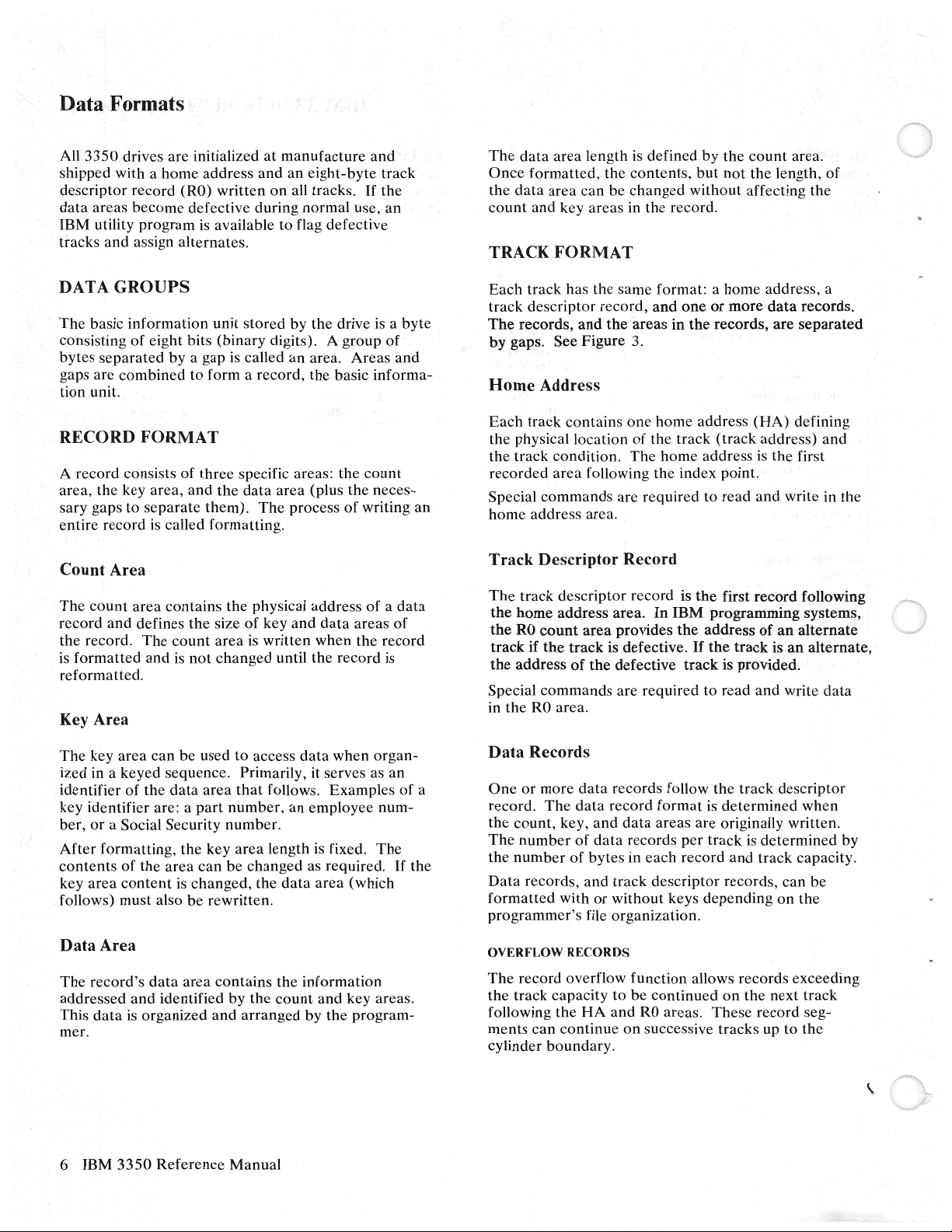
Each
track has the same format: a
track
descriptor record,
The
records,
by
gaps. See Figure 3.
Home
Each
track
the physical location
track
the
recorded
Special commands are required to read
home
Track
The
track descriptor record is
the
home
the
RO
track
if
the
address
Special commands are required to read and write
in the
and
Address
contains one home address
condition.
area
following the index point.
address area.
Descriptor Record
add.ress area.
count
area
the
track
of
the
RO
area.
and
the
areas
in
of
the
track
The
home address
In
IBM
provides
is defective.
defective
the
home
address, a
one
or
more
data
the
records, are
(HA)
(track
address) and
is
the
and
write in the
the
first
record
programming systems,
address
If
the
track
of
an
track
is
an
is provided.
records.
separated
defining
first
following
alternate
alternate,
data
The
key area
ized in a keyed sequence. Primarily, it serves as an
identifier of the
key identifier are: a
ber,
or
After
formatting, the key
contents
key area
follows) must also
can
be used to access
data
area
that
follows. Examples
part
number,
a Social Security number.
area
length
of
the
area
can
be
changed
content
is
changed,
be
rewritten.
the
data
when
organ-
an employee num-
is
as required.
data
area
fixed.
The
(which
If
Data Area
The
record's
addressed
data
This
mer.
6 IBM
data
and
is
organized
3350
area
contains the information
identified
and
Reference
by
the
arranged
Manual
count
by
and
key areas.
the
program-
of
a
the
Data
Records
One
or
more
data
records follow the track descriptor
The
data
record.
the
count, key, and
The
number
the
number
Data
records,
formatted
programmer's
OVERFLOW
The
the
following
ments
cylinder boundary.
with
record overflow function allows records exceeding
track capacity
the
can
continue
record
of
data
of
bytes
and
or
file organization.
RECORDS
HA
format
data
areas are originally written.
records
in each
track
descriptor records,
without keys depending
to
be
continued
and
RO
on
successive tracks up to
per
record
areas.
is
determined
track is
These
determined
and
track capacity.
on
the
record seg-
can
on
next track
when
by
be
the
the
Page 11
WRITE
Write padding
portion
completion of format writing. Padding begins upon
completion of writing initiated by a format write
command
chained.
PADDING
is
a process
of
a track with a special
if
another
format write command
of
filling
pattern
out
the remaining
following
is
not
3350
The
feature which
storage control to disconnect after the last format
write
while the original drive pads to
In this case, index orientation may be lost upon
reconnection to the channel.
(all modes) has a format write release
under
some conditions allows the
command
on
a track
and
to service
the
end
other
drives
of the track.
Data
Formats
7
Page 12
r
Index
Point
6
G1
,,..
/
Home
Address
G2
RO
Area
Count
Record Zero
RO
RO
Area
Data
G3
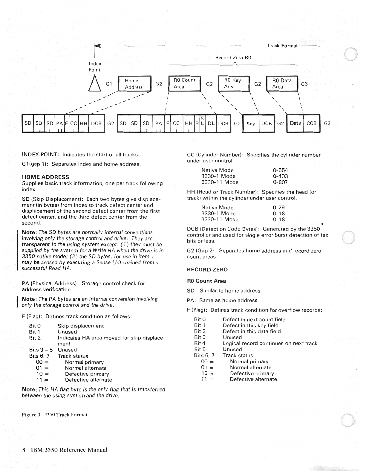
INDEX
G 1
HOME
Supplies
index.
SD
ment
displacement
defect
second.
Note:
involving only the
transparent to the using system except: ( 1) they must
supplied by the system
3350
may
successful
PA
address
Note:
only the
F (Flag):
Note:
between the using system and the drive.
POINT:
(gap
1):
Separates
ADDRESS
basic
(Skip
Displacement):
(in
bytes)
center, and
The
SD
native mode; (
be
sensed
Read
(Physical
verification.
The
PA
storage
Defines
Bit
0
Bit
1
Bit
2
Bits
3 - 5
Bits
6,
7
00
=
01 =
10
=
11
=
This
HA
Indicates
track
from
of
the
the
the
start
index
and
information,
Each
index
to
third
track
defect
defect
second
home
one
two
of
all
address.
per
bytes
defect
center
center
tracks.
track
give
center
from
from
following
displace-
the
the
bytes are normally internal conventions
storage
by
executing a Sense
HA.
Address):
bytes are
control and the
track
Skip
Unused
Indicates
ment
Unused
Track
Normal
Normal
Defective
Defective
flag byte is the only
control and
for
a Write
2)
the
SD
bytes,
Storage
an
internal convention involving
condition
displacement
HA
area
status
primary
alternate
primary
alternate
HA
control
drive.
as
moved
flag
drive.
for
1/0
follows:
They are
when the drive
use in
item
chained
check
for
that is
from
for
skip
displace-
transferred
and
first
1.
CC
(Cylinder
under
Native
3330-1
3330-11
HH (Head
track)
Native
3330-1
3330-11
DCB
(Detection
controller
bits
be
is
in
a
or
G2 (Gap 2):
count
RECORD
RO
Count
SD·
Similar
PA:
Same
F (Flag):
Bit
Bit
Bit
Bit
Bit
Bit
Bits
00
01
10
11
user
or
within
and
less.
areas.
ZERO
Area
Defines
0
1
2
3
4
5
6, 7
=
=
=
=
Number):
control.
Mode
Mode
Mode
Track
the
cylinder
Mode
Mode
Mode
Code
used
Separates
to
home
as
home
track
Defect
Defect
Defect
Unused
Logical
Unused
Track
Normal
Normal
Defective
Defective
Specifies
Number):
under
Bytes):
for
single
home
address
address
condition
in
next
in
this
in
this
record
status
primary
alternate
the
0-554
0-403
0-807
Specifies
user
0-29
0-18
0-18
Generated
error
address
for
count
key
field
data
field
continues
primary
alternate
cylinder
the
control.
burst
and
overflow
field
on
number
head
by
the
3350
detection
record
records:
next
track
(or
of
zero
,,
ten
Figure
3. 3350
Track
Format
8 IBM 3350 Reference Manual
Page 13
----
Track
Format
-------------------------------iaio1~
Data
Record
R 1-Rn /
Index
R1-Rn
Cnt
G3
~rea
',
'
G2
.._
--
''
1s1D1
s1DI
;~}I
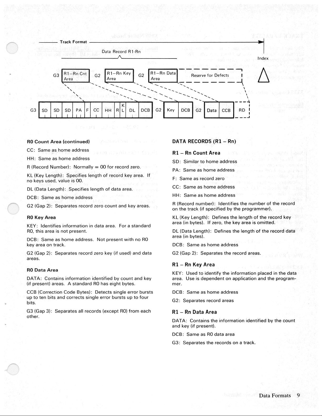
RO
Count
Area
(continued)
CC: Same
HH:
R (Record
KL (Key Length):
no
keys used, value is 00.
DL (Data Length):
DCB:
G2 (Gap
RO
Key
KEY:
RO,
this
DCB:
key area on track.
G2 (Gap 2): Separates record zero key
areas.
RO
Data
DATA:
(if present) areas. A
CCB (Correction
up
to
bits.
G3 (Gap 3): Separates all records (except
other.
as.home
Same as
Number):
Same
2):
Area
Identifies
area is
Same
Area
Contains
ten
bits
address
home
address
Normally
Specifies
Specifies
as
home
address
Separates record zero
information
not
present.
as
home
address.
information
standard
Code
and
Bytes):
corrects
cc 1
""
Hrl
=
00
for
record zero.
length
of
record key area.
length
of
data area.
count
in data area. For a
Not
present
(if
identified
RO
Detects
single error
has
by
eight
single
bursts
-------------,
G2
.........
.._
.........
"-..,
' --
..............
...........
--
.......
-
......
DL}CB1:m
If
and key areas.
standard
with
no
RO
used) and data
count
and key
bytes.
error
bursts
up
to
four
RO)
from
each
-:::'."",
-........
Reserve
______
......
.....
......
--..
- '-.. \
.....
............
for
Defects I
:+.::1
DATA
RECORDS
Rl -Rn
SD:
PA:
F:
CC:
HH:
R (Record
on
KL (Key Length):
area (in bytes).
DL (Data Length):
area (in bytes).
DCB:
G2 (Gap 2): Separates
Rl -Rn
KEY: Used
area. Use is
mer.
DCB:
G2:
Rl -Rn
DAT
and key (if present).
DCB:
G3:
Count Area
Similar
Same
as
Same
as record zero
Same
as
Same
the
number):
track
Same
Key Area
Same
Separates record areas
Data Area
A:
Contains
Same
Separates
(Rl -Rn)
to
home
home
home
as
home
(if
specified
Defines
If
zero,
Defines
as
home
to
identify
dependent
as
home
the
as
RO
data
the
records
address
address
address
Identifies
information
-\
\
',
CCB
[~~J
address
the
by
the
the
the
key area is
the
address
the
record areas.
the
information
on
application
address
area
on
number
programmer).
length
length
identified
a track.
of
the
omitted.
of
the
placed in
and
of
the
record
record key
record data
the
the
program-
by
the
count
data
Data
Formats
9
Page 14

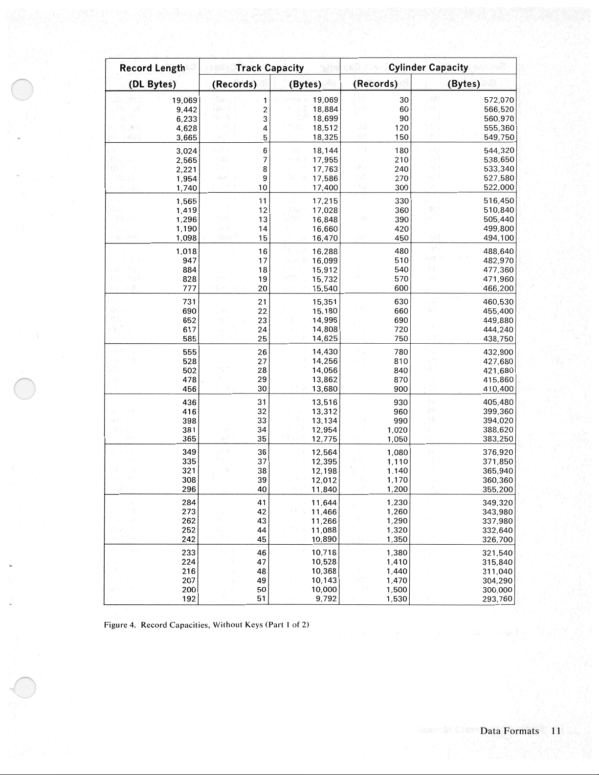
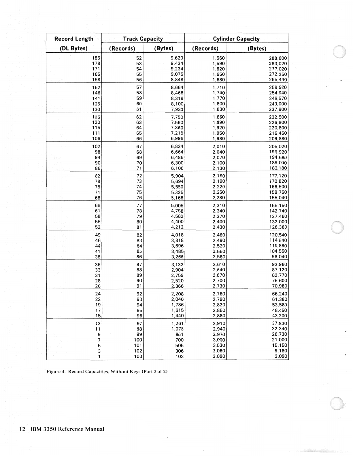
TRACK CAPACITY
3350
Native
Mode
The number
depends
following formulas
number
track.
allowance (overhead) has already
3330
Equal length records 13,165 (track
of
records
on
the record size and track capacity.
of
equal length records
The
home address,
Compatibility
track
that
can be recorded
can
be used to determine the
that
RO
space, and skip defect
Modes
C+KL+DL
per
track
The
can
be
placed
been
accounted for.
capadty)
(bytes per record)
where:
Note: When
the
DL
in
C = 135 if
= 1 91 if
KL
= Key
DL = Data
an
end-of-file (EOF)
the count area must be zero. The storage
KL
= 0
KL
# 0
Length
Length
mark
is
written,
control, however, adds a one-byte data area when
writing the
track balance routines must allow
EOF
mark. Programmers working with
for
this byte by
subtracting one byte from the track balance remain-
ing. The standard 135 -byte overhead allowance
should therefore
be
increased to
136
for
each
EOF
written.
The
number
lengths
of
one
Where
Where
13,298
of
records
that
can
be
the
following equations.
RO
is
standard:
13,165
RO
is
not
~[KL(O)+DL(O)+C-10]
(n)
of
different key and
recorded on a track must satisify
n
~~
(KLi+DLi+C)
i=
1
standard:
n
+~
i=l
data
[KLi+DLi+C]
on
Equal
length records
track
a
where:
C+KL+DL
C
KL
DL = Data
The
number
lengths
one
of
Where
Where
19,442
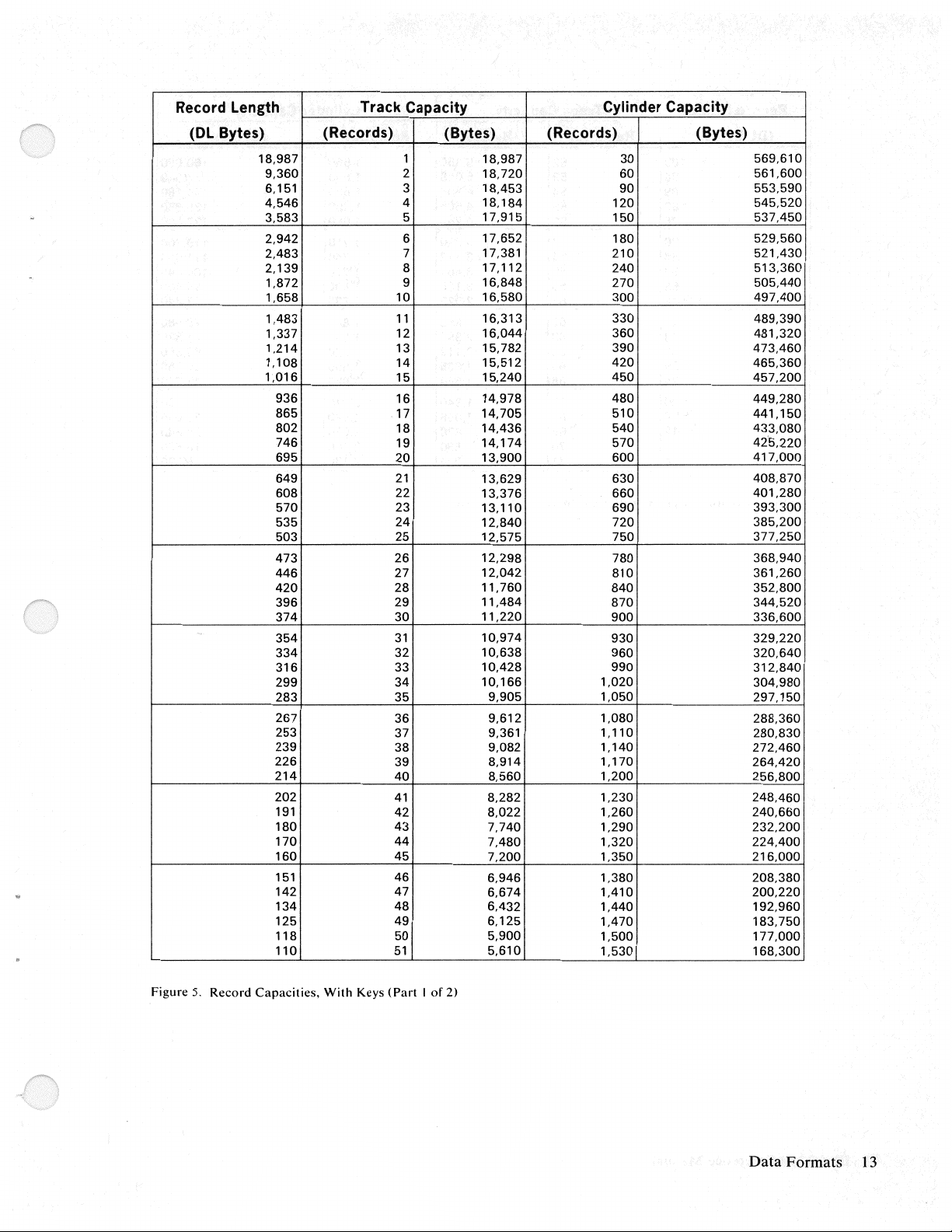
Figures 4
length records
capacity in both
records is shown.
keys, and
of
records
that
can
be recorded
the following equations.
RO
is standard:
n
19,254
RO
~[KL(O)+DL(O)+C-3]+~
~~
(KLi+DLi+C)
i=l
is
not standard:
and
5 give the maximum
on
a track.
number
There
one
with keys.
19,254 (track capacity)
(bytes per record)
= 185 if
= 267 if
= Key
KL
KL#
Length
Length
(n)
of
different key and
on
a track must satisify
n
[KLi+DLi+C]
i=
1
number
The
track
and
of
bytes
and
number
are two tables,
For
drives being used in
= 0
0
of equal
cylinder
one
without
data
of
compatibility modes, use the capacity tables in the
Reference Manual
Order
No.
GA26-1615.
for
IBM
3330
Disk Storage,
10
IBM3350
Reference Manual
Page 15
Record
length
(Dl
Bytes) (Records)
19,069
9,442
6,233
4,628
3,665
3,024
2,565
2,221
1,954
1,740
1,565
1,419
1,296
1,
190
1,098
1,018
947 17
884
828
777 20
731
690
652
617
585
555 26
528
502
478
456
436
416
398 33
381
365
349
335
321
308
296
284
273
262
252
242
233
224
216
207 49
200
192
Track
Capacity
1
2
3
4
5
6
7
8
9
10
11
12
13
14
15
16
18
19
21
22
23
24
25
27
28
29
30
31
32
34
35
36
37
38
39
40
41
42
43
44
45
46
47
48
50
51
(Bytes)
19,069
18,884
18,6991
18,5121
18,325
18,
17,955
17,763
17,586
17,400
17,215
17,028
16,848
16,660
16,470
16,288
16,099
15,912
15,732
15,540
15,351
15,
14,996
14,808
14,625
14,430
14,256
14,056
13,862
13,680
13,516
13,312
13,
12,954
12,775
12,564
12,395
12,198
12,012
11,840
11,644
11,466
11,266
11,088
10,890
10,718
10,528
10,368
10,143
10,000
9,792
144
180
134
Cylinder Capacity
(Records) (Bytes)
30
60
90
120
150
1801
210
240
270
300
330
360
390
420
450
480
510
540
570
600
6301
660
690
720
750
780
810
840
870
900
930
960
990
1,020
1,050
1,080
1,110
1,
140
1,
170
1,200
1,230
1,260
1,290
1,320
1,350
1,380
1,410
1,440
1,470
1,500
1,530
572,070
566,520
560,970
555,360
549,750
544,320
538,650
533,340
527,580
522,000
516,450
510,840
505,440
499,800
494,100
488,640
482,970
477,360
471,960
466,200
460,530
455,400
449,880
444,240
438,750
432,900
427,680
421,680
415,860
410,400
405,480
399,360
394,020
388,620
383,250
376,920
371,850
365,940
360,360
355,200
349,320
343,980
337,980
332,640
326,700
321,540
315,840
311,040
304,290
300,000
293,760
I
I
Figure 4. Record
Capacities,
Without
Keys
(Part I of
2)
Data
Formats
11
Page 16
Record Length
Track Capacity Cylinder Capacity
(DL Bytes) (Records) (Bytes) (Records) (Bytes)
185
178
171
165
158
152
146
141
135
130
125
120
115
111
106
102
98
94
90
86
82
78
75
71
68
65
61
58
55
52
49
46
44
41
38
36
33
31
28
26
24
22
19
17
15
13
11
9 99
7
5
3
1
52
53
54
55
56
57
58
59
60
61
62
63
64
65
66
67
68
69
70
71
72
73
74
75
76
77
78
79
80
81
82
83
84
85
86
87 3,
88
89
90
91
92
93
94
95
96
97
98
100
101
102
103 103
9,620
9,434
9,234
9,075
8,848
8,664
8,468
8,319
8,100
7,930
7,750
7,560
7,360
7,215
6,996
6,834
6,664
6,486
6,300
6,106
5,904
5,694
5,550
5,325
5,168
5,005
4,758
4,582
4,400
4,212
4,018
3,818
3,696
3,485
3,268
132
2,904
2,759
2,520 2,700
2,366
2,208 2,760
2,046
1,786
1,615
1,440
1,261
1,078
851
700
505
306
1,560
1,590
1,620
1,650
1,680
1,710
1,740
1,770
1,800
1,830
1,860
1,890
1,920
1,950
1,980
2,010
2,040
2,070
2,100
2,
130
2,
160
2,
190
2,220
2,250
2,280
2,310
2,340
2,370
2,400
2,430
2,460
2,490
2,520
2,550
2,580
2,610
2,640
2,670
2,730
2,790
2,820
2,850
2,880
2,910
2,940
2,970
3,000
3,030
3,060
3,090
288,600
283,020
277,020
272,250
265,440
259,920
254,040
249,570
243,000
237,900
232,500
226,800
220,800
216,450
209,880
205,020
199,920
194,580
189,000
183,180
177,120
170,820
166,500
159,750
155,040
155,150
142,740
137,460
132,000
126,360
120;540
114,540
110,880
104,550
98,040
93,960
87,120
82,770
75,600
70,980
66,240
61,380
53,580
48,450
43,200
37,830
32,340
26,730
21,000
15,
150
9,
180
3,090
12 IBM
Figure
4.
Record
3350
Reference Manual
Capacities,
Without
Keys
(Part 2 of
2)
Page 17
Record
(Dl
length
Bytes)
18,987
9,360
6,
151
4,546
3,583
2,942
2,483
2, 139 8 17, 112
1,872
1,658 10
1,483
1,337 12
1,214
1,108 14
1,016
936
865
802
746
695
649
608
570
535
503 25
473 26
446
420
396
374
354
334
316
299
283
267
253
239 38
226
214
202
191
180
170
160
151 46
142
134
125
118
110
Track Capacity Cylinder Capacity
(Records) (Bytes) (Records) (Bytes)
1
2
3
4
5
6
7
9 16,848
11
13
15
16
17
18
19 14,
20
21
22
23 13,
24
27
28
29
30
31
32
33
34
35
36
37
39
40
41
42
43
44
45
47
48
49
50
51
18,987 30
18,720
18,453
184 120
18,
17,915
17,652
17,381
16,580
16,313
16,044
15,782
15,512
15,240
14,978
14,705
14,436
174
13,900
13,629
13,376
110
12,840
12,575
12,298
12,042
11,760
11,484
11,220
10,974
10,638
10,428
166
10,
9,905
9,612
9,361 1,
9,082
8,914
8,560
8,282
8,022
7,740
7,480
7,200
6,946
6,674
6,432
6,
125
5,900
5,610
60
90
150
180
210
240
270
300
330
360
390
420
450
480
510
540
570
600
630
660
690
720
750
780
810
840
870
900
930
960
990
1,020
1,050
1,080
110
1,
140
1,
170
1,200
1,230
1,260
1,290
1,320
1,350
1,380
1,410
1,440
1,470
1,500
1,530
569,610
561,600
553,590
545,520
537,450
529,560
521,430
513,360
505,440
497,400
489,390
481,320
473,460
465,360
457,200
449,280
441,
150
433,080
425,220
417,000
408,870
401,280
393,300
385,200
377,250
368,940
361,260
352,800
344,520
336,600
329,220
320,640
312,840
304,980
297,
150
288,360
280,830
272,460
264,420
256,800
248,460
240,660
232,200
224,400
216,000
208,380
200,220
192,960
183,750
177,000
168,300
Figure
5.
Record
Capacities,
With
Keys
(Part I of
2)
Data
Formats
13
Page 18

Record Length
(DL Bytes) (Records)
103
96
89
83
76
70
64
59 59
53
48
43
38
33
29
24
20
16
12
8
4
Figure
5.
Record capacities, With Keys
Track
Capacity Cylinder Capacity
180
112
560
284
(Records)
1,560
1,590
1,620
1,650
1,680
1,710
1,740
1,770
1,800
1,830
1,860
1,890
1,920
2,010
2,040
2,070
2,100
2,130
52
53
54
55
56
57
58
60
61
62
63
64
65
66
67
68
69
70
71
(part
(Bytes)
5,356
5,088
4,806
4,565
4,256
3,990
3,712
3,481
3,
2,928
2,666
2,394
2,
1,885 1,950
1,584 1,980
1,340
1,088
828
2 of 2)
(Bytes)
160,680
152,640
144,
180
136,950
127,680
119,700
111,360
104,340
95,400
87,840
79,980
71,820
63,360
56,550
47,520
40,200
32,640
24,840
16,800
8,520
14
IBM
3350 Reference Manual
Page 19

Page of GA.26-1638-1
Revised
By
TNL:
Jan.
31, 1978
GN26-0342
This section describes the
Input/Output
operations
used with the 3350. Additional information about the
central processing unit
control of
System/
DR.IVE
Each
I/0
operations
3 70 Principles
MODES
3350
drive can be operated in one of three
(CPU)
is
found in The
of
Operation.
and channel program
IBM
modes: 3330-1 compatibility, 3330-11 compatibility,
or
3350
native. Units are shipped with drives format-
ted in the mode as specified by the customer. Changes
CE
in mode require
and customer action.
Drive Addresses
The
I/O
drive address
(Figure 6). The parity bit
made for odd parity and the remaining eight bits are
used to designate the required drive.
Bits 0 and 1 are the storage control address bits.
non-existent storage control is addressed, condition
code 3
On
is
indicated.
all real 3330, 3340,
either native or 3330-11 mode, there
logical volume
on
the 3330-1 mode, there are two logical volumes
drive.
The bit 2 function depends
If
the storage control has no
3330-1 compatibility mode attached, bit 2 (together
with bits 0 and 1) functions as a storage control
address bit.
If
any attached
3350
3330-1 compatibility mode, bit 2
correct logical device
(0), the primary logical device
dressed. When bit 2
device
is
addressed.
Bits 3 and 4 are the string address. This allows a
maximum of four storage strings to be attached to one
storage control. Each string (of up to eight physical
drives) may contain only 3350s, or only 3330s, or only
3340s (not 3344s); the
combination of compatibility and native mode 3350s.
If
bits 3 and 4 address a string
powered off, or disabled by the string switch, condi-
is
tion code 3
indicated.
is
an 8-bit byte plus a parity bit
is
discarded
or
3350
a drive. When a
on
the string configuration.
3350
after
drives operating in
is
only one
3350
operating in the
drives are operating in the
is
used to select the
on
the drive. When bit 2 is off
on
the drive is ad-
is
on
(1),
the secondary logical
3350
strings can be in any
that
is non-existent,
a check is
is
operating in
on
If
a
a
Input/
Bits 5, 6, and 7 select one of the eight drives
is
string. Unit check
down
or
non-existent. Addresses of the storage
controls and string controllers are established
user
and
plugged at installation by the CE.
A maximum of
returned
32
physical drives can be addressed
Output Operations
on
the
if
the drive
is
powered
by
the
through a single storage control. When 3350s are
operating in the 3330-1 compatibility mode, 64 logical
drive addresses are available. Smaller configurations
of 8, 16, or 32 drives can be addressed
but
require
different plugging arrangements by the CE. The
smaller addressing configurations require fewer unit
control words to be available in the channel.
Valid 3350 Addresses
When any
mode there are 36 valid secondary address ranges as
shown in Figure
and requires two logical addresses per spindle. When a
3350
mode and 3330s
storage control, only primary addresses can be used.
When the 3350s are operating in either 3330-11
compatibility
ranges are available for each storage control. These
address ranges are shown in Figure 8.
Additional addressing information is found in the
applicable storage control reference manual and in the
3350/3344
0
Storage
Control
Address
"
When
through
address.
Figure
3350
is operating in 3330-1 compatibility
7.
The
3350
operates as two
is
not
operating in the 3330-1 compatibility
and/
or
3340s are attached to the
or
3350
native mode, 72 valid address
Installation and Conversion Guide.
1
I
less
4 can
6.
Drive Addressing
2"
Logical
Drive
Selection
(3330-1
Compati-
bility
Mode
only)
than
64
become
3* I 4*
String
Address
(max.
Li,)
addresses are
part
of
the
storage
_ _j_
configured,
3330-ls
5
I 6 I
Physical Drive
Address
(max. 8)
bits
control
7
2
Input/Output
Operations
15
Page 20

I Primary j Secondary Addresses
~~.dresses
L---_0
__
0-_0_7
I 00-01_ 10--11 20-21,
I
I I
I
! 18-1F
00-0F
00-1 F
08-0F
08-0F, 18-1 F I 28-2F,
~------+--------1---------1
i
i-------------+-------+-------;
10-17
10-ff
----+-------+-------I
40-41
I
L 40-47,
I
I
r---------·------+-------+-------1
50-57
40-4F
50-5F
I . 58-5F
r----8_0-_8_7
- 80-87,
r 80-8F AO-AF
,____
__
! 80-9F 1 AO-BF
l
_____
Lss-sF,
~
___
L _
90-97
_
8_8_-8
__ F __
98-9F
90-J)_J
__
_jl0-9F~,
L 98-9F
I CO-C7
r-----------+--------+--------1
I CO-C7,
I
r------------~---~-------<
L
_____
!
i C8-CF E8-EF 16
r CS-CF,
~-Dc;--D--7----+---F-O--'---F7----+----1-6--~
1-
! !
L
___
00-07
CO-CF
c_o_-o_r_:
08-DF
DO-OF I
__Q_§::__9_i
I Addresses ReQuired
__
,__
__
2_0-_2_7
__
30-37
I 20-2F
20-3F
I
----it-------+------~
I
i
I
I
__
+i
___
,__
~!'--
~,
__
1-
___
~l
28-2F
30-37
30-3F
38-3F
60-s1
60-67,
60-6F
70-7F
___
7_8_-7_F
__
A_O-_A_7
AO-A7,
__
A_8_-_A_F
AB-AF, BS-BF
___
B_0_-_8_7
___
B_O_-_B_F
88-BF
EO-E7
EO-E7,
I
EO-EF
__
E_O_-_F_F
E8-EF, F8-FF
FO-FF
___
F_8_-F_F
38-3F
70-77
__
______
B0-87
__
__
__
FO-F7
__
__
.__
-+-
+-
--+-
+-
--1-
~
__
___
__
__
__
__
___
1_6 _ ____,
32
32
64
16
32
16
32
16
16
32
32
32
16_~-1
1_6 _ ____,
32
32
64
1_6
__
~
32
1_6
__
__,
3_2
__
~
16
16
32
32
6_4
__
~
32
32
16
__
~
Address Ranges Addresses
from
00
to
7F
00-07
00-07,
08-0F, 18-1 F 16
20-27,
28-2F,
40-47,
48-4F,
10-17
00-0F
00-1 F
08-0F
10-17
10-1 F 16
18-1 F 8
-20-27 8
30-37
20-2F
20-3F
28-2F
38-3F
30-37
30-3F
38-3F
40-47
50-57
40-4F
40-5F
48-4F
58-5F
50-57
50-5F
58-5F
60-67
60-67,
68-6F,
7060-6F
60-7F
68-6F
78-7F
70-77
70-7F
78-7F
77
Required from
8
16 80-87,
16
32
8
8
16
16
32
8
16
8
16
8
8
16
16
32
8
16
8
16
8
8
16
16
32
8
16 E8-EF, F8-FF
8
16
8
Address Ranges
80
to
FF
80-87
90-97
80-8F
80-9F
88-8F
88-SF,
98-9F
90-97
90-9F
98-9F
AO-A7
AO-A7,
A8-AF,
CO-C7,
C8-CF, D8-DF
AO-AF
AO-BF
A8-AF
80-87
BO-BF
88-BF
CO-C7
CO-CF
CO-DF
C8-CF
D0-07
DO-DF
08-DF
EO-E7
EO-E7,
EO-EF
EO-FF
E8-EF
FO-F7
FD-FF
F8-FF
B0-87
88-BF
D0-07
FO-F7
Figure
7.
16 IBM
Addresses
3350
Reference
for
3330-1
Compatibility
Manual
Mode
Figure 8.
bility
Mode
Address
Ranges
for
3350
Native
or
3330-11
Compati-
Page 21

Seek
Addresses
Seek
Time
A specific track
address
addresses consist
are zero, bytes 2
bytes 5
The
access mechanism.
tion
required track.
The
normally corresponds to bytes 2 through 5 of the seek
address.
preceding each
the physical cylinder
written by the storage control, are used for seek
verification.
When
control,
head
The acceptable seek address ranges for the
operating
Operating
Mode
Native
3330-1
3330-11
together
and
Byte 0 2 3 4 5
Function 0 0
cylinder address may require
of
the correct
CCHH
The
the seek address is received by the storage
it
address and
on a 3350
with a Seek command. All seek
of
exactly six bytes. Bytes 0,
and
3 specify the logical cylinder,
6 are the logical
The
head address involves selec-
read/write
part
of
the
count
three physical address
count
area
and
head
is
converted
modes are:
Data
cc
0-554
0-403
0-807
into the physical cylinder
sent
to
the
Tracks
HH
0-29
0-18
0-18
drive
is
selected by the seek
head
address to be used.
c c
head
area
and
home address reflect
address.
3350
H H
movement
to
cover the
and
home address
(PA)
The
for seek operations.
Alternate
Tracks
cc
555-559
404-410
808-814
by the
bytes
PA
3350
HH
0-29
0-18
0-18
and
bytes,
and
l
and
Seek time
heads
correct
cylinder
required for a
access time
25 milliseconds.
When
data
required.
Head
The
head
is
the time required to move the
to
the
correct
cylinder, the seek time
is
required, a minimum
one
is
50
fixed
head
is
in the fixed head cylinders, no seek time
Selection Time
time required
is
negligible.
Latency
The
3350
drives
revolutions
specific record
maximum
milliseconds
timing purposes.
3350s
All
capability permits
channel
record
used
period.
per
minute.
to
of
16. 7 milliseconds.
(the
utilize rotational position sensing. This
during the time required to bring the
to
the
read/write
by
the
channel
cylinder.
cylinder change.
milliseconds, and
models are involved
to
select the required
rotate
at
reach the
average delay),
the
drive to disconnect from the
and
If
the
heads
is
zero.
of
10
The
the
a nominal
The
time required for a
read/write
head.
storage
speed
Half
is
generally used for
Other
control
milliseconds
and
a revolution,
drives
read/write
are
at
the
If
a different
maximum
average time
the required
is
read/write
of
3600
heads
is
a
correct
can
be
during this
is
is
8.4
ACCESS AND DATA
The
total time required
consists of seek time
latency time,
and
data
(if
transfer
TRANSFER
for
access
and
required),
head
time.
data
transfer
selection time,
Data
The
nominal
1,
198,000
byte.
Transfer
data
bytes
Rate
transfer
per
second
rate
of
the
or
0.835
Input/Output
3350
is
microseconds
Operations
per
17
Page 22

DATA INTEGRITY AND SECURITY
The
3350
protects
and
error
correction.
provided through use
and
tion,
file protection.
data
integrity by
Data
of
security
write
error
and
protect,
detection
privacy are
seek verifica-
that
A non-compare indicates
not properly positioned.
reposition the access mechanism
If
command retry
ended
with unit check and sense information
equipment check,
indicated in
byte
is
unsuccessful, the operation
permanent
7,
message
the access mechanism
Command
error,
A.
retry
is
used to
to
the correct track.
that
and
seek
error
is
is
posts
Write
The write
erased
each drive causes any write command to
The
ed
the sense information indicates write inhibited (byte
bit 6)
Seek
The
count
verification. When the
processed during a read
bytes are compared with
Protect
protect
or
rewritten. A switch in the control panel
switch
or
can
not
busy.
and
command reject
Verification
3350
track format includes three
area
and
function prevents
be changed when the file
When
a write command
(byte
home address
count
or
search operation, the three
the
most
data
0, bit 0).
bytes
that
are used for seek
area
or
home address
recent
from being
of
be
rejected.
is
not
select-
is
rejected,
in
each
seek address.
is
l,
File Protection
The
Set File Mask instruction in a chain of channel
the
commands describes
can
be performed.
operation
status byte followed
bytes.
are used to indicate which functions are to be inhibited.
A description
in the
is
attempted,
The
various bits in
3830-2
of
the Set File Mask command is given
and
write and seek functions
If
an
inhibited write
a unit check is generated in the
by
command reject in the sense
the
Set File Mask command
ISC Reference Manuals.
or
seek
that
18 IBM
3350
Reference Manual
Page 23

Error
recovery usually involves storage
system-invoked actions.
vary
depending
on
how
These
and
recovery actions
to
what
attached.
the
Recovery actions involving
3830-2)
topics:
Table,
ERROR
The
and
the
Error
Correction
and
Error
CORRECTION
error
correction function
attached
Recovery Action.
recovery action procedure.
data
check
correctable
ECF
algorithms
are described in
(3830-2
ERROR
The
or
ISC).
CORRECTION
error
correction
bit configurations
0,
1,
and
bytes
2.
is
and
the
the
storage
table (Figure
set
by
Each
related recovery
of
storage
3350s
Function,
FUNCTION
(ECF)
It
is
used
posted
for a
control
TABLE
the storage
these unique configurations
requires a specific recovery action
the
system.
ERROR
The
the
tion
action table may specify
command
restart
RECOVERY ACTION
3350
recovery action table (Figure
actions
shown
to
in the
words.
CCWs
be
taken
error
The
follow.
for
condition table.
construct
instructions
each
sense
CCW Restart Construction
If
sense
byte
1,
error
occurred
error
recovery procedures
continue
the
operation
table specifies
RESTART
1.
2.
The
byte
The
plus
CCW 1
command
3.
data
the
residual count.
bit 7 (operation
after
data
transfer
normally.
the
restart
CONSTRUCTION
code
address
count
of
is
that
that
incomplete) is on,
can
correct
CCW
required,
byte
is provided in sense
of
the
CCW,
control
system the
control
are described in
Error
Condition
is
part
of
the
whenever
data
area.
procedure
reference manuals
9)
identifies sense
control
to
be invoked
restart
for
had
The
in sense
10)
specifies
byte
configura-
The
recovery
channel
constructing
started.
the
The
error
recovery action
either 1 or
interrupted
minus
the
CSW
and
can
3350
(ISC
three
a
The
by
an
and
CCW,
or
2.
Page of GA26-1638-I
Revised
By
TNL:
Jan.
31, 1978
GN26-0342
Error Recovery
3.
The
flags,
except
(PCI),
is
4.
The
the
command
specify a
read,
REST
ART
1.
The
The
2.
are those
count
residual
turn
CCW 2
command
count
a.
Fetch
was a write,
byte
on
CONSTRUCTION
CSW-8,
b.
Subtract
count
positive, go
program
of
is
the residual
count
is zero, use a
having '
the skip bit.
code
is
constructed
the
count
and
set a
the
restart
obtained
to
controlled
the
interrupted
count
in the CSW.
count
the
data
address should
00
' .
If
command
is
provided in sense
as follows:
of
the
CCW
pointer
to
this
displacement from the
in
step
a.
If
this result is
step
f;
otherwise, go
interrupt
CCW.
of
one.
was a
byte
designated
CCW.
to
step
If
If
3.
by
c.
c.
Check
designated
set, go
d.
Advance
CCW
count
CCWs
Truncation
e.
2
clude
f.
Set
result
step
3.
The
flags (except
designated
is
also
4.
The
data
by
the
CCW,
step
2.
If
another
during a
while executing the
CCW
count
the
the
of
3.
by
set
if
address
pointer
minus
operation
Read
can
be
the chain
by
to
step
the
pointer
in
the
data
to
the
counts
in the
occurred. Set
equal
skip
Restart
the
subtraction
PCI)
the
pointer
step
2e
is
in
step
the
restart
Multiple
generated
data
flag
of
the
CCW
the
pointer.
e; otherwise, go to
chain
of
data
chain.
to
1.
Go
bit
in
the
CCW 2 count
are those
If
to
the
next
and add
all previous
Return
the
to
step 3 and
restart
in
step
of
in
step
2.
the
flag is
step
non-TIC
this
to
restart
CCW
equal
b.
the
CCW
The
non-TIC
step
to
Go
skip bit
was previously executed.
that
of
the
CCW
designated
2e, plus the
CCW
incomplete
CKD
restart
CCW, a new
from the old
count
count
generated
or
an
command
restart
of
error
occurs
restart
not
d.
CCW
b.
CCW
in-
flags.
the
to
that
in
ccw.
Note:
Be
sure
to
avoid destroying the old restart
CCW
before generating the new one.
Error
Recovery 19
Page 24

Page
of
G A26-l 638-I
Revised
By
Error
Jan.
TNL:
GN26-0342
Correction Table
31, l 978
Bit
0
rB~e
i 1 .
~i
-·---
_}-+Equipment
rt=
,___...._._.
1
0
1 7
0
1
2 1
0
2 1
0 5
0 5
1 0
1 1 Invalid Track
1 2 End
1
1 7
1 4
1
I
1
1 7 I
I
1 7
2 3 Environmental
Command
Command
0
Write
6
--
1
Intervention
2 Bus
3 I
Equipment
_0_
Permanent
1
4 Data Check
i
4
I Data Check 0
Permanent
0
4 Data Check
Operation
4 Data Check
7
Operation
Correctable
4 Data Check
Correctable
10verrun
Overrun
Permanent
2
J End
I
Operation
I
No
5
I File
i
I
5 I File
Operation
Operation
I Data Present
Name
Reject
Reject
Inhibit
Required
Out
Parity
Check
Check
Error
Error
Incomplete
Incomplete
Error
Format
of
Cylinder
of
Cylinder
Incomplete
Record Found
Protect
Protect
Incomplete
Incomplete
Programming
A
write
in
the
Read
Drive
offline
out
Bus
Equipment
Equipment
storage
check
Data
command.
Uncorrectable
ed.
check
Data
but
not a data-field
Correctable
segment,
Correctable
the
last
Service overrun in
segment,
CKD.
Storage
Track
capacity
Cylinder
Cylinder
Record
The seek
violated
A read
After
start
either a defective
error
in
Statistical
error.
command
position.
or
not
parity
error.
malfunction.
malfunction,
control
overflow
control
not
the
or
the
retry
not
correctable
data check,
in
second
data
not
the
data
during a format
exceeded.
boundary
boundary
found
command
file
write
overflow
of
data
second
usage I
General
received
plugged
exhausted
or
correctable
check
last
segment.
check
segment.
second
retry
exhausted
detected
detected
in basic
or
mask.
transfer
or
alternate
or
subsequent
error
Description
with
the
for
the
or
with
a Read
storage
subsequent
error.
in
the
data area
in
the
data area
or
subsequent
write,
or
on
during
during
command
read/search
violated
log
the
during
track
information
write
inhibit
switch
address.
undesirable.
Multiple
control
overflow
of
or
a Read
a service overrun.
multitrack
overflow
sequence.
multitrack
file mask.
an
overflow
condition
segment
is present.
retry
exhaust-
segment
an
overflow
data area
overflow
Multiple
operation.
operation.
operation
operation,
or
a seek
was
found.
CKD
of
Action
2 No
1
3
3
4 s
·-1-
1
4
1 Yes
I
68
6
5
4 Yes
1
2
8
9
2
10
11
7
3 Yes
logged
No
Yes
(See Note.)
I
I
~
Yes
I
I
'
I
I
I
I
No
~
Yes
Yes
No
No
No
No
No
No
No
I
I
I
--
I
--
I
1
j
i
I
Note:
Figure 9.
20
IBM
If
sense byte 10, bits 4 and 5 are zero,
Error
3350
Correction
Reference
Table
Manual
no
recording action
is
performed.
Page 25

Page of GA26-1638-1
Revised
By
TNL:
Jan.
31, 1978
GN26-0342
Recovery
Action
Action
1 Print console
2
3
4
5
5A
58
Note#:
byte
Get the cylinder bytes and the high-order head byte
from sense
Table
error
message
Exit
with
programming
a.
Repeat the operation once.
b.
If
the error
Repeat the operation.
a.
b.
If
the
a.
Perform error correction
Examine
b.
has been corrected. (User is operating in
c.
Examine
otherwise, continue
If
the user's chain has
of
this
Note:
non-TIC
d. Continue the user's chain
Seek (see
Set File
Read Home
Search Equal ID (CCHHR
TIC*-8
TIC (CSW)
Continue
Seek (see
Set File
Read Home
Search Equal ID (CCHHR
TIC*-8
Read
TIC (CSW)
This action is used
been processed. Reconstruct
a.
Construct
b.
Set
command
Restart the operation
Seek
Set File
Read Home
Search Equal ID (CCHHR
TIC*-8
Read
TIC (CSW)
byte
6, bits
condition
error
condition
bit 7 of
the
CCW
If
data chaining is indicated in the interrupted
CCW
Mask
the
user's chain by executing:
Mask
Count
Mask
Mult
the
interrupted
is on (count area).
past the last
Addr
Addr
to
Restart
code
Addr
CKD (from step
3-7.
for
operator
error
or
unusual condition indication.
persists,
persists
function.
file mask (PCI).
CCW
with
this
not
been completed, examine the
CCW
by
executing
restart a Read
the
CCW
2.
to
'5E'.
through
the
do
after
step.
Read
following
Explanation
and I
or
customer
action
1.
10
retries,
If
off,
go
PCI
(CSW-8):
go
to
If
step d.
it
is a Read
If
in the data chain.
the
following:
Note
# below)
(same as original)
(skip
bit
on)
from
(channel status
Note
# below)
(same as original)
(skip
bit
on)
from
(skip
bit
on)
(channel status
Multiple
(see
(same as original)
(skip
(if
CKD data recovery process
Multiple
Note#
bit
user's chain has
CKD as
chain:
below)
on)
from
b)
from
engineer notification, (see Figure 10,
do
action
1.
to
step
c.
If
on, return
fetch
mode
and
Multiple
next
non-TIC
bit
3 is
off,
do
action 5A.
CCW,
the preceding test must
sense bytes 8-12)
word)
sense bytes 8-12)
word)
follows:
sense bytes 8-12)
not
been completed)
to
must
supply
CKD
command ( '5E').
CCW
after
user
with
indication
own
restart recovery action.)
in
the
user's chain.
be
a correctable data check has
part
4).
that
the
do
action
58;
If
bit
executed on the
the user, not from the sense bytes. Get the low-order head
data
3
first
Figure I
0.
Recovery Action
Table
(Part
I of 4)
Error Recovery
21
Page 26

Page
ot
0A26-l
638-I
Revised
By
Jan.
31, 1978
TNL: GN26-0342
Recovery Action Table (continued)
Action
6
68
a.
Perform error
b. Examine
has been corrected. (User is operating in
Increment
c.
d.
Construct
e.
Complete
Seek
Set
File
Set
Sector
Search ID Equal (record
TIC*-8
Restart
TIC (CSW)
Note:
If
the modified seek argument is not within the user's extent,
before issuing the Seek.
a.
Examine
been corrected. (User is operating in
b.
Construct
Complete
c.
following:
Seek (see
Set
File
Set
Sector
Search ID Equal
TIC*-8
Restart
TIC (CSW)
Note:
before issuing the Seek.
If
the modified seek argument is not within the user's extent,
bit 7 of
the
restart
the
Mask
CCW
bit 7 of
restart
the
Mask
CCW
correction
the
file
seek
argument
CCW
interrupted
2
If
that is impossible,
the
file
CCW
interrupted
2
If
that
function.
mask
2.
operation
mask
2.
operation
is
impossible,
(PCI).
by
(PCI).
Explanation
If
off,
go
to
PCI
one
(see
and
(argument
(same as original)
(argument
(channel
If
off,
PCI
and
Note
(same as original)
(argument 0)
(record
(channel
fetch
Note#
continue
from
0)
1)
status
word)
/OS
must
go
to
fetch
mode
continue
# below)
1)
status
word)
/OS
must do action 2.
step
c.
mode
below).
the
user's
step
c)
do action 2.
step
b.
and
the
user's
If
on, return
and
must
chain
If
on, return
must
chain (if appropriate) by executing
to
user
with
indication
supply
(if
IDS
must
supply
/OS
must supply the correct seek argument
own
restart recovery action.)
appropriate) by
executing:
supply the correct seek argument
to
user
with
indication
own
restart recovery action.)
that
that
the
data has
the
data
'
Note#:
byte from
Figure 10. Recovery
Get the cylinder bytes and the high-order
sense byte 6, bits
Action
3-7.
Table
(Part 2 of
4)
head
byte
from the user, not from the sense bytes. Get the low-order head
22
IBM
3350
Reference Manual
Page 27

Recovery Action
Table
(continued)
Action
7
8
9
a.
Construct
Construct
b.
c.
Continue
Seek
Set
Set
Search ID Equal (record 1)
TIC*-8
Restart
TIC (CSW)
a.
Increment
b.
Continue
Seek
Set
Set
Read
TIC
Note:
If
before issuing the Seek.
a.
Increment
b.
Construct
c.
Complete
following:
Seek
Set
Set
Search ID Equal
TIC*-8
Restart
TIC
Note:
If
before issuing the Seek.
seek
argument
restart
user's
File
Mask
Sector
CCW
the
File
Mask
Sector
Home
(CSW-8)
1
the
cylinder
operation
Addr
CCW
chain
the modified seek
the
cylinder
File
Mask
Sector
CCW
(CSW)
restart
the
CCW
interrupted
1
(see
1.
by
executing
address
by
executing
argument
If
that is impossible,
address
1.
operation
the modified seek argument is not within the user's extent,
If
that is impossible,
Explanation
Note#
below).
the
following
(argument
(same as original)
(argument
(channel
of
the
(argument
(same as original)
(argument
(skip
(channel
status
user's
the
following:
bit
on)
status
from
0)
seek
from
0)
word
chain:
step
a)
word)
argument
step
a)
-8)
is not within the user's extent,
/OS
must do action 2.
of
the
user's
seek
argument
and
continue
(argument
(same as original)
(argument
(record
(channel
1)
status
IOS
from
O)
must
the
step
word)
do
user's
a)
action 2.
by
one.
/OS
by
one. Reset
chain
(if
/OS
Set
the
head
address
to
zero.
must supply the correct seek argument
the
head address.
appropriate)
by
executing
the
must supply the correct seek argument
Note#:
byte
from
Figure
Get the cylinder bytes and
sense byte 6, bits
I 0.
Recovery
Action
Table
3-7.
(Part 3 of
high-order
4)
head byte
from
the user, not
from
the sense bytes. Get the
low-order
Error
Recovery 23
head
Page 28

Recovery Action
Table
(continued)
Action
10
10A
11
a.
Determine
b.
Continue
Seek (user's
Set
Set
Sector
Read
TIC (CSW) (channel
Note:
If
before issuing the Seek.
a.
This
Continue
b.
Seek
Set
Set
Read
TIC
Note:
If
before issuing the Seek.
a.
Increment
b.
Construct
c.
Complete
following:
Seek
Set
Set
Search
TIC*-8
Restart
TIC (CSW) (channel
if
the
interrupted
the
operation
File
Mask
Home
Addr
the modified seek
is a
multitrack
the
operation
File
Mask
Sector
Home
(CSW-8)
Addr
If
operation.
command
by
executing
argument
that is impossible,
by
executing
the modified seek argument is not within the user's extent,
If
that is impossible,
the
user's
seek
argument
restart
CCW
1.
the
interrupted
File
Mask
Sector
ID
Equal (record
CCW
1
operation
Explanation
is a seek.
the
following:
argument,
(same as original)
(argument
(skip
bit
on)
status
is not within the user's extent,
/OS
Increment
(argument
(same as original)
(argument
(skip
(channel
the
following:
bit
on)
status
the
/OS
by
one
and
continue
(argument
(same as original)
(argument
1)
status
O)
must
user's
from
0)
must
(see
from
0)
If
yes,
see
word)
do
step
word
do
Note#
the
step
word)
go
Note#
action 2.
seek
a)
-8)
action 2.
below).
user's
a)
to
step
b.
If
not,
below)
IOS
must
supply the
argument
chain (if appropriate)
/OS
by
one (see
must
supply the
do
action
correct
Note#
correct
by
executing
10A.
seek argument
below).
seek argument
the
Note#:
byte
from
Figure
10.
24 IBM
Note:
If
the modified seek argument is not within the
before issuing the Seek.
Get the cylinder bytes and the
sense
byte
6, bits
3-7.
Recovery
3350
Action
Table
(Part 4 of
Reference Manual
If
that is impossible,
high-order
4).
head
byte
/OS
from
user's
must
do action 2.
the user, not
extent,
from
/OS
must
supply the
the sense bytes. Get the
correct
seek argument
low-order
head
Page 29

The
following commands are recognized
11
by the 3350. (See Figures
The three diagnostic commands are on(v used when
microdiagnostics from the
CONTROL
•
No
Operation
• Recalibrate
• Seek
• Seek Cylinder
• Seek
• Space
• Set File Mask
• Set Sector
•
Restore
• Diagnostic
• Diagnostic Write
SEARCH
• Search
• Search ID Equal
• Search ID High
• Search ID Equal
• Search Key
• Search Key High
• Search Key Equal
COMMANDS
Head
Count
Load
COMMANDS
Home
Address
or
Equal
High
or
through 16.)
System/
Equal
High
and
executed
3 70 are required.
READ
•
•
•
•
•
•
•
•
•
SENSE
• Sense
• Sense
• Read
• Diagnostic Sense
• Device Reserve
COMMANDS
Read
Data
Read
Key
Read
Count,
Read
Record
Read
Count
Read
Home
Read
Initial
Read
Sector
Read
Multiple
COMMANDS
1/0
1/0
and
Reset
and
Data
Key,
Zero
Address
Program
Count,
Type
and
Load
Buffered
I • Unconditional Reserve
• Device Release
FORMAT
• Write
e Write
• Erase
• Write
• Write Special
WRITE
Home
Record
Count,
COMMANDS
Address
Zero
Key,
and
Count,
Key,
Channel Commands
Data
Key,
and
Data
Log
Data
and
Data
UPDATE
• Write
• Write
Key
WRITE
Data
and
COMMANDS
Data
Channel
Commands
25
Page 30

CONTROL COMMANDS
Command
No
Operation
Recalibrate 13
Seek
Seek Cylinder
Seek Head
Space
Count
Set File
Set
Restore
Diagnostic Transfers
Load
Diagnostic
Write
Mask
Sector
Code
Single
Track
03
07
Multi-
track
No
during initial status.
Moves
Moves
1.
address. Only
2. Selects the head specified
OB
18
OF
1F
23 eliminate
17
53
73
Selects head specified by
When
command, locates
RO),
end and device end in gap
When
HA, G2, and
following
Sets
commands.
Used on disconnected
tion
No
channel end and device end.
only storage
Transfers and executes inline
storage control. A
stored
transferred
command. (See sense commands.)
action. Channel end and device end presented None
chained
spaces over
not
file
with
action. Zero initial
Function
the
access
access
chained, searches
RO
mask
the
the storage
the
in storage control. Message
to
cylinder 0 and selects head 0.
to
cylinder specified by the seek Six address
by
the
the
seek address. Six address bytes. Only
from
read, search,
start
of
the
count
RO
count
area. Ends
count
with
channel end and device end.
to
control
need
specified
to
the
to
main storage by a Diagnostic Sense
operation
command
for
the
control
status
512-byte
storage
16-byte
channel
write,
next
count
area, and ends
before
key
for
index, spaces over G
chaining channels
during rotational delay.
followed
data
control
test
from
error code message is
Data
Transferred
Across
None
bytes
seek address. are used
address.
five
are used.
or
space
count
area (including (one byte) and DL
with
channel bytes)
area. mand.
operation
of
to
maintain
buffer.
may
in gap
write
and seek One
connec-
by
final
status
block
from
main storage
then
be
Three bytes used as KL
1,
data.
to
One
angular
(0-127).
of
None
read One
formation
one
only storage.
Maximum
to
for
lowest
for
byte
byte
track
byte
sector
Channel
bytes
2,
3,
and 5
the
seek
bits
of
next
com-
of
file
mask
that
specifies
position
of
control
addresses
on
the read
of
512
bytes.
(0-5).
byte
(two
in-
5
Figure I I.
Control
Commands
26 IBM 3350 Reference Manual
Page 31

SEARCH
COMMANDS
Command
Search Home
dress Equal
Search ID Equal
Search ID High
Search ID Equal
High
Search Key Equal
Search Key High
Search Key Equal
High
Ad-
or
or
Single
Track
39
31
51
71
29
49
69
Code
Multi-
track
89
81
D1
F1
A9
C9
E9
Function
Locates a
argument.
Locates a
Locates a
(Locates any ID
from
Locates a
(Locates ID
the ID
Locates a key area selected
(The key area compared is
chained
from
record.)
Locates a key area selected by
(Same as Search Key Equal except
than system key.)
Locates a key area selected
(Same as Search Key Equal
higher than system key.)
home
address area selected
count
area selected
count
area selected
from
the
system.) drive and track
count
area selected
from
track
that
from
system.)
from
a Read
a Read Count, the key searched is in
Count
track
is equal
by
from
or
by
except
by
by
that
by
the
Search ID.
the
the
by
the
search
the
search argument. Five bytes (CCHHR)
the
search argument. Five bytes (CCHHR)
is higher than the ID
the search argument.
to
or
higher
than
search argument. Key bytes
the
next
record unless drive and track
If
chained
the
same
search argument. Key bytes
finds
any key higher
searc~h
argument. Key bytes
key is equal
to
Four bytes (CCHH)
HA
drive and track,
CCHH
next
lected
with
system.
next
CCHHR
Five bytes (CCHHR)
next
drive and track
CCHHR
from
drive and track
from
drive
or
from
Data
Compared
area
from
from
count
drive
CCHHR
count
from
count
from
system.
system.
from
and track
system.
selected
with
the
system.
area
from
and track,
from
area
from
with
system.
area
from
with
system.
from
selected
with
from
selected
with
selected
with
of
of
se-
the
of
of
key
key
key
Figure
12.
Search
Commands
Channel Commands 27
Page 32

READ
Read Data
Read Key and Data Transfers key and data areas
Read Count, Key,
and Data drive
Read Record Transfers
Zero
Read Count
Read Home Address
Read Initial
Program Load
Read Sector Transfers one angular position byte used by next Set One byte
Read
Key, and Data number
COMMANDS
Command
'
(RO)
Multiple
Count, Transfers remaining records on track
Single
Track
06
OE
1E
16
12
1A
02
22
5E
Code
Multi-
track
Transfers data area
storage.
86 area
main storage. after address marker
If
BE
9E
96
92
9A
KL = 0, same as Read Data. the key and data areas
Transfers count, key,
to
main storage. cord
RO
storage.
If
chained
immediately
Transfers next
storage.
Transfers five bytes (FCCHH)
Recalibrates
point, and reads
Cannot be preceded by Set File
in same chain.
Sector.
is position
not
chained, is position required
record processed by the drive.
Resets orientation information.
than the longest track length and SILi
to
suppress incorrect length.
Command retry may be affected.
(count, key, and data)
from
with
count
to
cylinder 0, head 0, searches
If
chained
of
the record used in the previous CCW.
of
bytes unknown,
of
record
and
Search
no search
area (8 bytes)
R1
data
from
Function
from
drive
of
record
data areas
from
HA
or
Read HA, is executed
for
index.
from
to
main storage. Byte 0
from
drive
to
Mask
a read, write,
to
access the last
CCW
count should be larger next record (except
to
main First data area after ad-
from
drive
of
record
from
drive
to
drive
to
for
main storage. on cylinder 0, head 0.
or
Space Count
or
search CCW,
to
channel. Since Starts
bit
should be on
dress marker
of
from
count
same record.
to
First key and data areas
that
were
chained
area
of
Next record
after
main Record Zero
main Next record
or
first
RO.
Byte 1 = Cyl
Byte 2 = Cyl
Byte 3 = 0
Byte 4 = Head
index First data area
position data.
If
Data
Read
or
record chained
from
the
count area after
=Flag
at
data
or
key
of
command
the count
same record.
or
first
RO.
(RO).
count
Addr
Addr
Addr
after
of
angular
count field
re-
area
RO
of
RO).
or
Figure
28
13.
Read
Commands
IBM.
3350 Reference Manual
Page 33

SENSE
Command
COMMANDS
Code
Function
Data
Across
Transferred
Channel
Test
1/0
I 0
Sense I
Sense
Read and Reset
Buffered
Diagnostic
Sense
Device
Reserve
Unconditional
Reserve
Device
Release
Type
1/0
Log
Single
Track
00
E4
04
A4
44
84
14
94
Multi-
track
Determines status
automatically
required.
Transfers seven
storage
Note:
Read
sense bytes 18 through 23.
Determines
reset
Supplies usage
drive.
Data is reset upon transfer.
Determines
diagnostic
test
Reserves addressed device
channel on
machines.
Count
Same
alternate path.
string
tion.
Terminates
es
Mask
sense bytes.
control
When
HA, the skip displacement information appears in
upon
transfer.
test
to
system
multichannel
Cannot
in same chain.
as Device Reserve
switch.
or
string
or
Space
of
device on channel. Generated One status byte.
by channel
bytes
type
the Sense
cause
or
type
of
(part
after a Diagnostic
Resets
Used
device reservation on
switch
Count
when
of
sense data
and
drive
1/0
is chained
of
last
unit
error
logging
error(s)
follow a Set
machines.
found
of
Diagnostic
for
interfaces
Also
transfers
except
information
to
recover
in same chain.
status
type.
check. Sense data is
exclusive use by
from
Cannot
information
designating
from
data on
File
is routed
the
when
running 16
Write)
Load.
or
string
Mask
24
sense bytes.
in original path and
hardware
multichannel
follow a Set
Also
a successful
addressed
or
transfers
switch
or
Space
through
malfunc-
interfac-
File
transfers
7
bytes
trol
and drive
tion. (See Note.)
24
bytes
formation.
24
bytes
ror
logging
bytes
message
or
512
bytes
24
sense bytes.
24
sense bytes.
24
sense bytes.
24
of
storage
of
of
of
of
identifica-
sense
usage
data.
error
code
test
con-
in-
or
er-
data.
Figure
14.
Sense
Commands
Channel Commands 29
Page 34

FORMAT WRITE COMMANDS
Command
Write
Count, Key,
and Data and track.
Write
Special Count, Same as
Key, and Data
Erase
Write
Home
Address
Write
Zero
(HA)
Recqrd
(RO)
Single
Track
1D
01
11
19
15
Code
Multi-
track
Writes
Must
ful
a record
of
Same as
count, key, and data areas.
byte,
In
home
3350
home
3350
HA
Note:
Read
sense bytes 18 through 23.
Writes
Write
successful Search HA.)
one
chain
Search ID Equal,
overflow
or
ECG
3330
compatibility
address area on selected drive and track. In
native mode,
address area on selected drive and track.
native mode,
with
When
HA,
count, key, and data areas
CKD
Function
complete
(If
file
from
Write
overflow
record.)
Write
bytes are
CCW
the Sense
record on the selected cylinder Count, key, and data
mask violated, sets
Write
RO,
Write
or
Search Key Equal.)
CKD
except
for
segment.
CKD
except
writes
must
count= 4 or
written
modes,
11-byte
chain
1/0
is
(No~
no
No
more
chained from a successful
writes
command
CKD, Erase, success-
flag
bit
4 (on) indicating
used
for
information
address marker, sync
with
this
command.
5-byte
(SD SD SD
from
successful Search
if
flag
bit 6 off.)
reject. areas
last
segment
is
written
(FCC
FCC
(If
the skip displacement information appears in
of
RO_,
(Same as Flag
except
must
chain
from
Write
HA
or
Data
Written
of
next
cord. Data area
system;
flags, gaps
control.
Same as
in Bytes
HH) The
byte
HH) dress transferred
system. (See Note.)
HH R KL DL
system
Key and data
system.
count
Write
of
zeros.
5-byte
(3350)
byte
for
from
(3330)
home
from
count
track
area,
CKD.
HA.
DL
from
re-
from
storage
or
11-
ad-
from
CC
from
area.
Figure
15.
Format
Write
Commands
UPDATE WRITE COMMANDS
Write
Write
, Figure
Command
Data Changes data area
Key and Data
16.
Update
Write
Code
Single
Track
05
OD
Commands
Multi-
track
Function
of
a record.
sets
command
Search ID Equal
Changes key and data areas
same as
mand reject.
Write
reject.
Data.
Must
Must
or
Search Key Equal.)
If
file
chain
from
Data
(If
file
mask violated, Data
chain
from
successful
of
record. (If KL = 0, Data
mask
violated, sets
successful Search ID.) KL DL DL bytes in
com-
from
number
DL
DL
from
number
area
of
as specified
bytes in count.
as specified by
same record.
Written
system. Byte
by
system. Byte
count
30
IBM 3350 Reference Manual
Page 35

Sense Data
The status
sense bytes. There are 24 bytes
formats.
and
condition
Four
formats, 1, 4, 5,
of
the
3350
is
reported in the
and
seven different
and
6 describe the
3350. The remaining three formats, 0, 2, and 3 are
associated with the storage control.
Only the formats used with the
3350
are explained in
this manual. Refer to the following manuals for
formats 0, 2, 3, and a detailed description
of
unit
status:
• Reference Manual for Integrated Storage Control,
Order
No.
GA26-1620.
• Reference Manual for
Control,
Order
No.
3830
GA
Model 2 Storage
26-1617.
SENSE
BYTE
SUMMARY
In all the formats, the first eight bytes, 0 through 7,
give high-level information concerning status
and
condition. Sense byte 7 identifies the format in which
the remaining bytes, 8 through 24, are arrayed:
• Bits 0 through 3 indicate the format type for bytes
8 through
24
0
0 0 0 1
0 1 0
0
0 1 1
1 2
1 0 1
3
0
0 6
Format
1
4
5
• Bits 4 through 7 define a message
4
0 0 0
5 6
7
0 0
Message
I I I I I
I I I
'V
1 1 1
'V 'V
I I
'V 'V
1
F
Each
of
the formats concerned with the
3350
is
summarized in Figures 1 7 through 26. Figure 22
contains the applicable message for
formats. Should the indicated format be 0, 2,
each
of
the
or
3,
refer to the appropriate storage control manual for
interpretation.
Sense Data
31
Page 36

Page
of
Revised
By
TNL:
GA26-l
638-I
Jan.
31, 1978
GN26-0342
SENSE
Byte
Byte
Byte
Byte
Byte
Byte
Byte
Byte
BYTES 0
0
1 Permanent Invalid End
2
3 Restart
4 Physical Drive Identification
5
6 (See Note.)
3350/3330-11
3330-1
7 Format Message Code
THROUGH
BitO
Command
Reject ti on Bus
Error
Unused Correctable
0
128
High-order
(CE)
1024
(CE)
1024 16
7 SUMMARY
1 2
lntervenRequired Parity
Track Cylinder Found Protected Inhibited
Format
1
I
64
I
logical
512
256 0
(Bits
Channel
Out
of
Alternate
Controller mental
Selected Data
Command
'06'
= Read operation;
2
I
low-Order
32 16
I
Cylinder Address
256
0
through
3)
3
Equipment
Check
Unused
Environ-
Present
(provided only
3
I
logical
4
Data Check Overrun Unused
No
Record File
Compatibility
Mode
when
byte 1,
'05'
=
Write
(1
out
of
4
I
Cylinder
I
Address
8
8
5 6
Unused Unused
bit
operation
8 coding)
5
I
4
I
Logical Head
4 2
I I
(Bits 4
Write
7 is on.)
I
I
through
7
Unused
Operation
Incomplete
Unused
I
I
I
7
1
1
6
2
7)
Note:
When
the
CE
cylinder
are zeros.
Figure 17. Sense Bytes 0
1024
(in all models) is addressed, byte 6,
through 7 Summary
bit
0 = 1 and all other cylinder bits in bytes 5
and
6
32
IBM
3350
Reference
Manual
Page 37

3350 SENSE BYTES
SENSE BYTE 0
Bit 0
Command
Reject
Bit 1
Intervention
Required 3.
Bit 2
Bus
Out
Parity
Bit
3
Equipment
Check
Bit 4
Data Check
Bit
5
Overrun channel.
1. Invalid
2.
Invalid
3. Invalid
4. Track
5.
6.
7.
formatted
Write
portion
Write
command
also set.
Format
1. Drive addressed
Drive addressed
2.
Diagnostic
Addressed
4.
The storage
command
An unusual
in bytes 7
1. A correctable data error
correction
An uncorrectable data error
2.
byte
7.)
1.
Storage
2.
Data
byte
or
uninstalled feature
command
or
incomplete
write
control
reject).
hardware
through
data in
control
was
sequence.
without
of
file
received
attempted
not
not
Write
or
device in
has
23.)
bytes
received
received
argument
mask
physically
ready (HOA
Load
CE
detected a parity
condition
command
home
violated.
for
device
on
defective
command
mode
and
in
detected
15
through
detected
the
byte
too
late
issued.
transferred
address.
with
track.
attached
not
powered-up).
issued and
not
available
error in
the
channel,
in
information
22.)
in
information
from
the
from
the
by a control
Write
to
system.
the
storage
drive
channel
command.
Protect
microdiagnostic
for
received
switch
use.
data
transferred
control,
from
from
a drive. (Condition
before
the
last
during a write
or
on. Byte
is
resident
from
(Condition
drive.
a drive.
byte
read
operation.
1,
bit 6 (write
in
control
the
channel (not a
2,
(Byte
further
was
accepted by
further
bit
1 on, and
inhibited)
storage.
defined
defined
in
the
The
storage control posts overrun only
CCW
Data
of
the record is padded with zeros. All data overruns are
overruns occurring on second
operations.
If
the overrun exists
Bit
6,7 Unused --set
Figure
18.
Sense
Byte 0
Description
if
one
of
the above conditions occurs more than ten times in
chain, in the second
transmission is stopped when overrun is detected.
to
0.
after
or
later segment
or
higher record segments and overruns occurring during format
com171and
retry
of
overflow record,
is exhausted,
or
If a write
retried
byte
1,
during a
was
by
bit
0 (permanent
format
write
in progress, the remaining
the storage control except
error)
operation.
part
for
write
is posted.
Sense
Data
33
Page 38

3350
SENSE
Bit
0
Permanent
Error
Bit
1 1.
Invalid
Track
Format
Bit
2 1. A
End
of
Cylinder
Bit
3
Bit
4
No
Record area
Found
Bit
5 File
File
Protected
Bit
6
Write
Inhibited
Bit
7 One
Operation
Incomplete
BYTES
Storage
2.
2.
Unused --set
1.
2.
1.
2.
3.
An
also set.
1.
2.
3.
4.
5.
6. Seek
control
An
attempt
Index
was
(programming
multitrack
An
overflow
incomplete,
Two
index
or
without a write,
Access
Seek
Multitrack
Overflow
Overflow
Overflow
Correctable
0,
Defective
Uncorrectable
position
mask
violated
command.
attempt
of
made
the
following
bit
4, data check, also set.)
error
retry
was
made
detected
error).
read
or
operation
also set.)
to
0.
points
sensed in
verified
by:
read
or
operation.
to
write
to a file
beyond
or
found
occurred
protected
cylinder
data error
alternate
data
in
count
to
in
gap
search
attempted
search
(Byte 1,
on
found
track
error
second
SENSE BYTE 1
exhausted
write
data
following
attempted
to
command
sense,
or
control
before
the
command.
bit
7 also on.)
drive
with
when
overflow
boundary.
boundary.
in
data
found
after
found
in any area -
or
later
and
not
exceeding
count
or
to
go.
go
past
chain
command.
bit
is
posted
Read
Only
record
(Byte 1,
(Byte 1,
area -
not
start
segment.
successful.
the
track
key area
beyond
the
with
of
not
the
cylinder
no
intervening
(programming
switch
was
bit
5,
file
bit
2,
end-of-cylinder,
last
segment.
data
transfer.
first
segment.
capacity.
during
read
or
search
cylinder
boundary. (Byte 1,
set
processed:
protected,
on.
(Byte
boundary.
read in
error).
Byte
0,
also set.)
also set.)
2,
operation
bit
home
address
bit
0,
command
bit
1,
correctable, and
7,
operation
or
data
reject,
byte
See sense
Figure 19. Sense Byte 1
Description
34 IBM 3350 Reference Manual
byte 3 for
restart
command,
and
bytes 8 through
13
for
restart
information.
Page 39

3350
SENSE
BYTES
Bit
0
Bit
1
Correctable
Bit
2
Bit
3
Environmental Data
Present
Bit 4
Bits
5-7
Bits
0-7
Restart
Command
0-7
Bits
Physical
Drive
Identification
SENSE
--
set
to
Unused
Indicates
pattern and restart displacement.
Alternate
Indicates
If
1,
Unused
This byte identifies
Bit
that
controller
that
drive is operating in a
--
When
0 = drive 0,
0.
data error posted in byte 0,
selected.
bytes 8
through
23
3330
set
to
0.
SENSE
byte
1,
bit
the
bit
1 = drive
7 is set,
this
0000
0110
SENSE
physical drive selected.
1,
BYTE
2
bit
4 is correctable. Bytes
contain either usage, error statistics,
compatibility
BYTE
byte
= Read
(Zero
BYTE
and so on. The
mode.
3
shows
If
0, drive is operating in native mode.
the operation in process
0000
when
byte
1,
bit
4
bit
number
7 is
is equal
0101 =
off.)
15
Write
to
through
or
at
the
22
identify
error
log information.
the
time
of
interrupt:
drive number.
error
Bits
0-7
Low
Order Logical
Cylinder Address
Figure
20. Sense Bytes 2
Bit
Cylinder
through S Descriptions
SENSE
Identifies
low-order
0 1 2
128
64
BYTE
eight
32
5
bits
of
the
current seek argument.
3
16
4
8
5
4
6 7
2 1
Sense
Data
35
Page 40

Page
of
Revised
By
TNL:
GA26-1638-I
Jan.
31, 1978
GN26-0342
SENSE BYTE 6
This byte identifies the logical track address and cylinder used in the current Seek.
high-order
*When
can address any valid head.
address
Bit
No. 3350 Native
bit;
bits 3 through
0
1
2
3
4
5
6
7
CE
cylinder 1024 is addressed,
7 indicate the logical track.
or
3330-11
CE
Cylinder
Cylinder 256
bit
0=
Compatibility
Cylinder*
512
1 and all
other
cylinder
Mode
Logical Head
Logical Head 8
Logical Head 4
Logical Head 2
Logical Head 1
bits
of
16
bytes 5 and 6 = 0.
SENSE BYTE 7
Bits
0-3
Format
Type
Bits
4-7
Message·
Code
Specifies
0000
0001
0010
0011
0100
0101
0110
Also
*
displacement
Message code indicating
format
may be presented on errors
of
sense bytes 8
(Format
(Format
(Format
(Format 3) Storage control checks.
(Format 4)
(Format
(Format
0)
1)
2)
5)
6)
information.
through
Programming I system checks.
Device checks.
Storage
ECC
uncorrectable data checks.
ECC
correctable data checks*.
Usage I error statistics.
which
type
of
error; defined on Format Message page. (See Figure 22.)
23 as
control
are
follows:
equipment
not
ECC
checks.
correctable
0
Bits
3330-1
through
Compatibility
CE
Cylinder*
Cylinder
Cylinder 0
Bits 3
but
which
2 indicate the
Mode
256
through 7 of
require restart
byte
6
1
Figure 21. 3350 Sense Bytes 6
36 IBM
3350
Reference Manual
and
7 Descriptions
Page 41

3350 FORMAT MESSAGES (Sense Byte 7)
P1;tge
of
GA26-1638-I
Jan.
Revised
By
TNL: GN26-0342
31, 1978
Message
Number
i---
FORMAT
No
0
1
2.
3
4
5
6
7
8
9
A
B
c
D
E
F
message
Transmit
target
error data check
Microprogram
detected
Transmit
difference
high error
Sync
out
timing
error
Unexpected drive
status
at
initial selection
Transmit
, cylinder error in key area
(string
switch
Transmit
error in data area
Transmit
difference
Unexpected file
status during
Read IPL
Seek
error
Retry seek
plete
or
compare
equipment
No
interrupt
from
drive
Defect
re-orientation
check
Device
undetermined
at initial selection
Retry orientation
check
skipping
type
1
errors
only)
head
error
or
retry on retry
incom-
sector
non-
(with
check)
* Also may be presented on errors
require restart displacement
information.
FORMAT4
HA
area Unused
data check
Count area Unused
Key area
data check
ECC
uncorrectable
data checks data
No
sync
byte
in
HA
area
No
sync byte
in
count
area
No
sync
byte
No
sync
byte
Unused
No
address
mark
detection
which
are
not
ECC
FORMATS
Unused
ECC
correctable
checks*
correctable
but
which
Figure 22.
Format
Messages
Error Recovery 3 7
Page 42
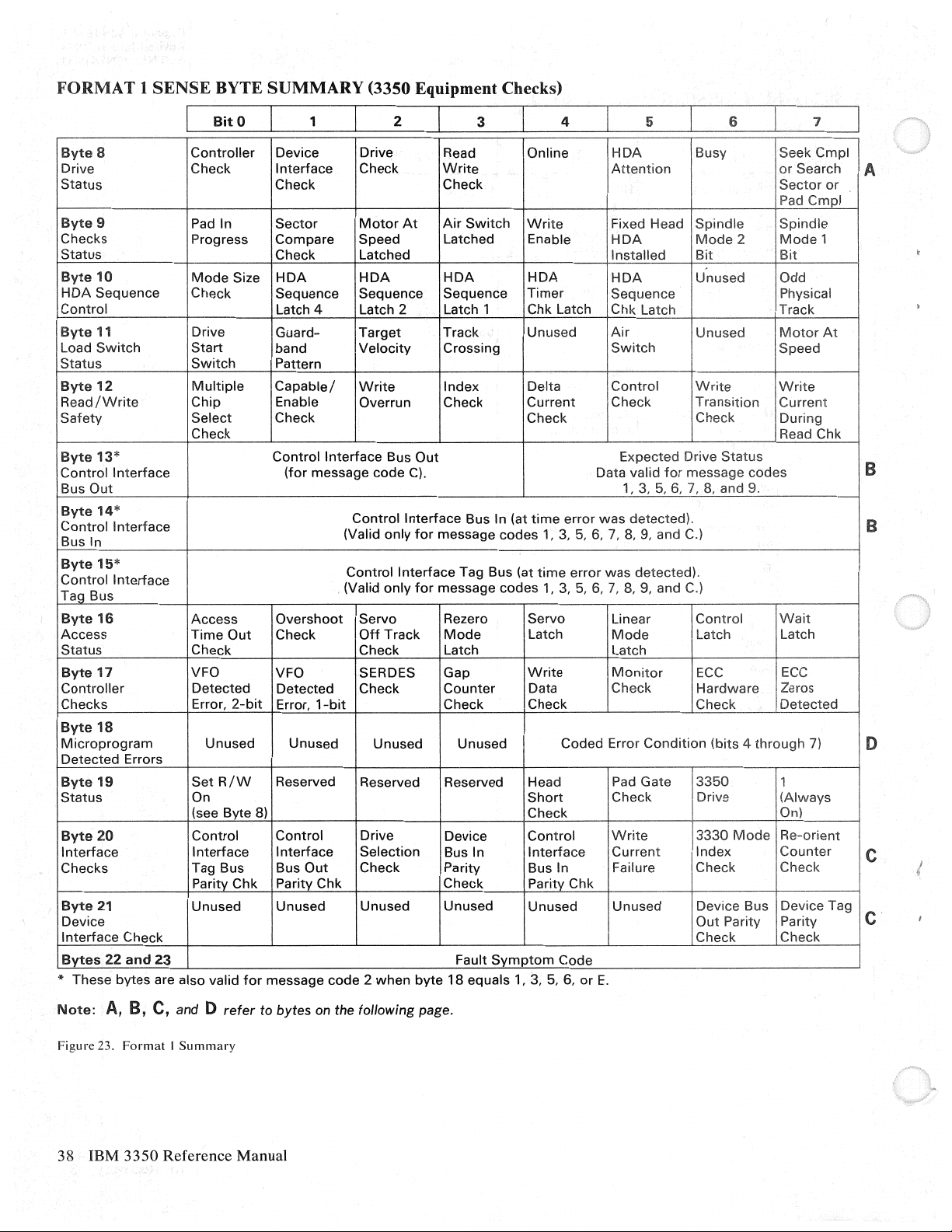
FORMAT 1 SENSE
~~-e-8-----.--C-o-n-tr_o_ll_er-~D-ev_i_c_e--~D-r-iv-e-------.~R_e_a_d
Drive Check
Status
Byte
9 Pad In
Checks Progress
Status
1----------1------1------+--------<-----+-----+------<--~
Byte
10
HOA
Sequence
,_C_o_n_t_ro_l
i
Byte
Load
Status
Byte
Read
Safety
Byte
I
Control
rB_u_s_O_u_t
____
11
Switch
12
/Write
13*
Interface
____
BYTE
L
BitO
Mode
I Check
-+-
____
Drive
Start
Switch
Multiple
Chip Enable Overrun Check
Select
Check . i Read Chk
_,_
_____
SUMMARY
1
Interface
Check Check ! j
Sector
Compare
Check Latched Installed I
Size
HDA HDA HDA HDA
Sequence Sequence Sequence
,_L_a_tc_h_4
__
Guardband
Pattern ,
Capable/
Check Check
Control
(for
message
~------~------~------1_,3_,_5_,_6_,
(3350 Equipment Checks)
2 3
__
____,_O_n_li_n_e
Check
Motor
Speed Latched Enable I
_,__La_t_c_h_2_---+_L_at_c_h_1
I
Target
Velocity
Write
Interface
Bus
code
At
C).
Out
Write
Air
Switch
___
Track
Crossing
Index
Write
Timer
.,_C_h_k_L_a_tc
Unused
Delta
Current
-~
4
__
.-H_D_A
Attention
5 i s
lsusy
!
~------i
I Fixed Head I
HDA
1
1
HDA
Sequence
__
h_+-1 C_h_k_L_a_t_ch._j__ i
Air
Switch
lcontrolj
1
Check
1
Expected Drive
Data valid
Spindle
1
Mode
Bit
I
Unused
I Phvsical
I
Unused : Motor
[
1
1
write
Transition
1
'I
Check i During
Status
for
message
7,
8,
and9.
2
codes
\seekCmpl
1
I
'Mode
J_Speed
!Write
'Current
7
or
Search
Sector
Pad
S:inpl
Spindle
Bit
Odd
Tr~ck
----i
1 !
At I
or
J
I
I'
j
I
I
I
1'
I
i B
~
A
~b~~r~~l*nterface
Bus In (Valid
f---~------1-~--~------~-----------~--~~-~-~-~~--~-~------j
Byte15*
Control
Interface
Control
Control
(Valid
Interface
only
for
Interface
only
for
Bus In (at
message
Tag Bus (at
message
codes
codes
time
1,
time
1, 3,
error
3,
5,
error
5,
was
detected).
6,
7,
8,
9, and C.) I
was
detected). I
6,
7,
8,
9, and C.)
_J
i B
I
:
1
lI_~_u_s~~-~+-----~~~~--~---~---~-~~~~-~---~--~-~-~~-~
I
Byte
16
Access
Status
Byte
17
Controller
Checks Error,
Byte
18 I
Microprogram
Detected
Byte
Status
Errors
19
1--~-~~-~--+c(_s_ee_B~y_te_B~l,__
Byte
20
Interface
Checks Tag Bus Bus
1------~---1-P_a_r_it~tv_C_h_k_rP_a_r_it_,__vC_h_k--<1-------+-C_h_e_c_k~~-+-P_a_rit~y_C_hk_+--~~--t---~~~-+-~~---;
Byte
21
Device
Interface
Bytes
* These
22
bytes
Check
and
Access
Time
Out
Check Check Latch Latch 1
VFO VFO SERDES Gap
Detected
Unused
Set R /W
On
Control Control
Interface Interface
Unused
Overshoot
Check
Detected
2-bit
Error,
Unused Unused Unused
Reserved Reserved Reserved Head Pad Gate i
___
Out
Unused
Servo
Off
Track
Check
1-bit
__,~~~~-+---~~C~he_c_k
Drive Device
Selection
Check Parity Bus In Failure Check
Unused Unused
Rezero Servo Linear I
Mode
Counter
Check Check Check I
Bus In
Latch
Write
Data
Coded
Short
__
._,_~~-~~L___~---~nl___~--j
Control
Interface
Unused Unused
Mode
Monitor
II
Check
Error
Condition
Control
Latch I Latch
ECC
II
Hardware
3350
Check I Drive 1
j
Write
II
Current
3330
Index
, Device Bus I Device Tag I
I
Out
I Check I Check I
23
are also valid
for
message
code 2 when
byte
Fault
18
equals 1,
Symptom
3,
Code
5,
6,
or
E.
I.
Wait
~I
lEcc
! Zeros '
Detected
i r
(bits 4
through
Mode i Re-orient
Parity I Parity C
7)
1
1
·1
(Always
'
1
Counter
1
I,
Check I
1
I
1
D
11
I
I
I
I C
Note:
Figure
A,
23.
38 IBM
B, C,
and D
Format I Summary
3350
Reference
refer
to
bytes
Manual
on the following page.
Page 43

A
If
busy
If
set read
(bit
6 on), Search
/write
is on (byte 19,
Sector
is in progress.
bit
0 = 1), byte 8 is read
as
follows:
0
Controller
Checks Sense
B
With
message code A
1 2 3
Write
0
Previous Seek
128
High Physical Cylinder
dr
SS
512
C
If
equipment
indicate:
check is on (byte 0,
0
128
High Physical Cylinder
dr
SS
512 256
Current
or
Address
64
Ad-
256
64
Ad-
4 5
Drive Check
B (byte 18,
Read/Write
Check
bits 4 through
7), bytes 13 and
On Line
14
2 3 4 5
(access
bit
2 3
Present Seek
32
32
3)
32
32
position
and
with
Address
before
present seek,
16
16
message
code
8
Physical Head
8
A indicated in
4
(low
physical
16 I 8 4
Physical Head
16
8 4 2
indicate:
bytes
cylinder
Padin
Progress
5 and 6)
Low
Physical Cylinder.
4
Address
4
byte
7,
bits 4
through
5 6
address)
Address
6
Index
6
Mark
2
2
7,
bytes
2
7
3330
Modes
7
20
and
7
21
D
Microprogram
Unused 8
0
1
No
No
2
operations.
No response
3
Time
4
ECC
5
6
Multiple
Preselection check. F Unresetable interrupt.
7
error messages (sense
tag
valid on
normal
out
hardware
read/write
or
check end on
from
waiting
or
for
check. D Unused
no
controller
byte
18, bits 4
operation. 9
read/write
drive on
control
index.
selected. E
or
ECC
operation. B Busy missing
through
7)
A
c
Repetitive
Repetitive
Incorrect
Unused
Always
active
command
command
drive selected.
after
overruns on G 1 operations.
overruns.
seek
bit
on
bus
start
in.
was
issued.
Sense Data 39
Page 44

FORMAT 4 SENSE
BYTE
SUMMARY
(ECC Uncorrectable
Data
Checks)
Byte
Cylinder
Address
Byte
Cylinder
Address
Byte
Head
Address
Byte
Head
Address
Byte
Record
Number
Byte
Sector
Number
Byte
Byte
8
9
10
11
12
13
22
23
BitO
1
High-order
Low-order
High-order
Low-order
Record
number
2 3
cylinder
cylinder
head
head
of
Zero
Sector
number
byte
of
byte
of
byte
of
byte
of
the
record in last
if
error
occurred
of
Fault
Fault
4
the
last
count
area read. (See Note.)
the
last
count
area read. (See Note.)
the
last
count
area read. (See Note.)
the
last
count
area read. (See Note.)
count
area read. (See Note.)
in
home
address.
the
record in error. (See Note.)
symptom
symptom
code.
code.
5 6 1
Note:
The
occurred in count area),
Figure 24.
information
Format 4 Summary
in
these
or
bytes
9
(AM
is unreliable
detection failure on
if
the message code
retry).
in
byte
7 is 0
or 4 (error
occurred
in
HA), 1
or 5 (error
40
IBM
3350 Reference Manual
Page 45

Page
of
Revised Jan. 31, 1978
By
GA26-1638-J
TNL: GN26-0342
FORMAT 5 SENSE
Byte
8
Cylinder
Address
Byte
9
Cylinder
Address
Byte
10
Head
Address
Byte
11
Head
Address
Byte
12
Record
Number
Byte
13
Sector Sector
Number
Byte
14
Unused
Byte
15
Restart
Byte
16
Displacement
Byte
17
Byte
18
Error
Byte
19
Displace-
ment.
Byte
20
Error
Byte
21
Pattern
Byte
22
BYTE SUMMARY
BitO
Error
displacement
Error pattern used
1 2 3
High-order
Low-order
Record
High-order
Low-order
location
(ECC
Correctable Data Checks*)
cylinder
cylinder byte
head byte
number
Specifies the
storage control
of
first
for
byte
head byte
of
the
number
byte
error
correction
of
the
last
of
the
last
of
the
last
of
the
last
record in last
of
the record in error.
Unused.
number
to
in error
of
bytes processed
the end
within
function.
4 5
count
area read. (See Note.)
count
area read. (See Note.)
count
area read. (See Note.)
count
area read. (See Note.)
count
area read. (See Note.)
by
the
of
the area in question.
the data area measured
(See Error Correction Function.)
from
the
end
of
7
area.
Byte
23
Unused
Note:
The
(error
information in bytes 8 through 12 is unreliable
occurred in count area).
* Also may be presented on errors which are not
Figure 25.
Format 5 Summary
ECC
Unused.
if
the message code in byte 7
correctable
but
which require displacement information.
is
0 or 4
(error
occurred in HA)
Error Recovery
or
1
41
Page 46

FORMAT 6 SENSE BYTE SUMMARY (Usage and Error Statistics)
Byte
Byte
Byte
Byte
Byte
Byte
Byte
Byte
Byte
Byte
8-11
Bytes
Read
or
Searched
12-13
Unused
14-15
Retry
Data
Errors
16-
17
Number
of
Seeks
18
19
Seek
Errors
20
21
22
23
'\,
BitO
These
control
These
These
1
four
bytes provide an accumulated
in read
or
search operations. Bytes processed during retry
two
bytes contain the
two
bytes provide
Bit 0 set
Bit 0 set
to
to
count. Only
zero = bytes
one = bytes
Total
number
(Seek errors
2
key
number
the
number
20
20
of
Command
Data overruns, channel A
eommand
Data overruns, channel B
3
count
and data area
Unused.
of
initial
ECC
control.
of
seek
through
through
seek errors retried
23 contain
23 contain
found
on retry are
overruns, channel A
overruns, channel B
4
of
the
number
counts
uncorrectable data errors retried
commands
are accumulated.
information
information
by
the storage control.
not
or
or
5
of
bytes processed by
operations
processed by the storage control.
for
for
included.)
or
C.
C.
or
D.
D.
are
interfaces A and
interfaces C and
6
not
included in
by
7
the
storage
the storage
B.
D.
this
Figure 26.
Format 6 Summary
42 IBM
3350
Reference Manual
Page 47

Operator Controls and Indicators
OPERATOR
Each
3350
drive. The indicators and controls for each
panel are shown in Figure 27.
EJ
START
STOP
Figure 27. 3350
PANEL
unit has two
ATIENTION
~
~
Operator
operator
Panel
panels,
one
R/W
READ
Ready Lamp
The Ready lamp turns
disk drive speed
track.
on
when the drive
is
up to normal,
and
is
the head
for each
operator
(.:;)
~
on, the
is
on
Attention
When pressed, the Attention pushbutton starts a
rezero operation. Rezero moves the heads to cylinder
zero, resets the address registers, and signals attention
to the controller.
end interrupts are generated for
Read,
When in the Read position, no write
can be performed.
writing operations are possible.
is
changed during an operation, the condition does not
change until the operation is completed.
Start/Stop
The drive
drive. When set
disks rotate up to speed, and the heads move to
cylinder zero. When set to Stop, the heads retract, the
a
brake engages,
interlock in the Stop position prevents a stop
drive
Pushbutton
R/W
Start/Stop
is
busy.
On
Switch
If
Switch
to
Start, the brake
and
the disks stop.
a drive
set to
toggle switch starts and stops a
in
3330-1 mode, device
both
logical devices.
or
erase operation
R/W,
all reading
If
the switch position
is
released, the
An
electrical
and
if
the
Operator
Controls and Indicators 43
Page 48

POWER
CONTROL
PANEL
(A2/
A2F)
A and B Enable/Disable Switches
A power control panel
of each A2 or
Figure 28.
A2F
Enable Enable
A~
Disable Disable
Figure 28. 3350
Power
Pressing the Power
applied to the string if the Power switch
Enable position.
On
A2/
Switch
is
mounted
dual-drive unit and
B~
A2F
Power
On
switch allows ac power to be
on
the front cover
[E]
Enable
Power
Off
Control
Panel
is
shown in
is
in the
These switches are used to select the active interface
in
3350
systems that have the optional string switch
feature.
CONTROLLER
ASSIGNMENT
PANEL
(C2/C2F)
A controller assignment panel
or
C2F
unit and
is
shown in Figure 29.
is
mounted on each
C2
Primary I Alternate Switch
This two-position toggle switch
controller
Primary, the A2
When set to Alternate the
controller. String power must be off before this switch
is changed. During a power up sequence, the online
controller
Primary
is
online, primary
or
A2F
unit
is
determined by the position of the
I Alternate switch.
Primary I Alternate Indicators (C2
One of these indicators
primary
or
alternate controller
is
is
used to select which
or
alternate. When set to
is
the online controller.
C2
or
C2F
unit
is
the online
or
C2F Units)
on to indicate whether the
is
online.
Power Switch
ENABLE
With the switch in the Enable position, the string may
be powered up by pressing the Power
a system-controlled power up sequence.
OFF
When the switch
powered down and string power cannot be restored
until the switch
Power
The Power
applied to the drive as controlled by the Power
On/Off
On
switch and the subsystem sequencing.
is
set to Off, the entire string
is
set to Enable.
Indicator
On
indicator is on when ac power is
On
switch
is
or
by
A
Enable tt
~isable~
Primary
©
Figure 29. 3350
B
Enable i
gisable~
Alternate
~
C2/C2F
0
Controller
Assignment Panel
44 IBM
3350
Reference Manual
Page 49

Index
A
AC
power
Access
drive
fixed
head
head
selection
maximum
mechanism
minimum
time
Addressing
drive
drive
variations
address
number
number
types
logical
physical
storage
string
Alternate
Area
count
data
key 6
Attaching
!SC
I
system/370
3830-2 I
Attention
44
rotation
models
17
2
17
I
15
ranges
of
addresses
of
strings
of
strings
drive
selection
drive
control
15
Controller
6
6
3350
models
pushbutton
17
time
15
IS
17
16
16
43
17
16
15
16
Commands,
control
read
25
search
sense
write
Compatibility
with existing
3330 Model I 3
3330 Model
Control
code
diagnostic
diagnostic
function
no
recalibrate
restore
seek 26
seek
seek
set file
set
space
Controller
assignment
function
primary/alternate
Controller
Correctable
Cost
Count
Cylinder
25
25
25
commands
26
operation
26
cylinder
head
mask
sector
count
assignment
per
byte 1
area
address
channel
25
mode
storage
11
load
write
26
26
26
26
26
26
panel
2
data
checks
6
26
26
3
26
17
26
44
switch
panel
3
44
44
41
B
Brake,
drive
Bus
out
Byte 6
Bytes (see
parity
c
Capacity,
DL
bytes
tables
with keys
per
per
without
per
per
Capacity,
formulas
native
number
compatibility
3330
CCW
restart
restart
restart
Channel
Command
Command
43
20
sense
bytes)
record
11
11
cylinder
track
12,
keys
cylinder
track
11
track
10
mode
10
of
records
construction
CCW 1 19
CCW 2 19
commands
reject
set
I
12, 13,
13,
11
(see
20
33
14
14
I 0
10
commands)
25
D
Data
formats
groups
integrity
record
count
data
file
key
seek
write
security
sense
track
format
data
home
track
Data
area
Data
base/data
Data
check
Data
rate
Data
records
Data
transfer
Defects
skippable
track
Device
release
Device
reserve
Diagnostic
Diagnostic
Direct
access
6
6
18
format
area
area
6
protection
area
6
verification
protect
18
31
records
address
descriptor
6
communications
20
I
6
rate
6
6
29
29
evaluation
sense
29
storage
6
18
6
17
18
18
6
record
2
6
Index 45
Page 50

Disable switch 44
Drive
addresses
modes
rotation
selection
Drives
function 2
modes
operator
power
Dual-drive
15
15
17
15
15
panel
control
storage
E
Enable
switch 44
End
of cylinder 20
Environmental
Equipment
Equipment
Erase 30
Error
correction
error
general description 20
Error
correction
correction
recovery
CCW
restart
storage
system-invoked
data
check 20
checks 38
function
correction
function
table
action
restart
CCW
control
F
File
protected
File
protection
Fixed
Format
head
20
18
1
messages
G
Glap
6
II
liead/Disk
Head
Home
I
Index
Indicators
alternate
power
primary
ready
Input/
Integrated
Intervention
Invalid
Assembly
selection time
address 6
point
6
44
44
44
lamp
output
track
43
operations
Stornge
required 20
format
43
44
4
present
(ECF)
table
19
19
19
construction
required
19
19
37
(HOA)
17
15
Control
(!SC) 3
20
20
19
K
Key
area
6
L
Latency, drive
M
Macro
orders
Models
alternate
controller
dual-drive storage 4
fixed
system/370
3330-1 1
3330-11 1
3350 4
3350 A2, A2F 1
3350 B2, B2F 1
3350 C2, C2F 1
controller
head
2
1,
4
1,
4
1
4
N
Native
mode
19
description 3
3350 3
No
record
found
20
0
Operation
Operator
Overflow records 6
Overrun
p
Panel
Permam:nt
5
Physical address
Power
Power
Primary
Privacy 1
R
Read
Read
Read
Read
Read
Read
Read
Read key
Read multiple
Read
Read
incomplete
panel
20
controller
operator
power
control
on
indicator
on/
off
switch 44
control
controller
commands
and
reset
count
count,
data
home
initial
and
record zero
sector
controls
assignment 44
43
44
error
20
(PA)
44
panel 44
adapter
28
buffered
28
key,
and
data
count,
(RO)
data
load
28
key,
28
address 28
program
28
20
43
17
log 29
28
28
and
28
4
data
28
46 IBM 3350 Reference Manual
Page 51

Read
only
Ready
lamp
Record
rorrnat
count
data
key
area
Recovery
action
explanation
Remote
Rotational
switch
area
area
action
21
switch
position
43
43
6
6
6
table
21
attachment
sensing
Storage
String
Switch
4
1
System/3
Systems
subsystem
switch
feature
alternate
disable
enable
enable/disable
primary
remote
4
44
44
44
44
4
70
models
residence
4
l
I
s
Search
commands
Searcli
home
Search
Search
Search
Search
Search
Search
Security
Seek
address
Seek
verification
Sense
Sense
byte
byte I 34
byte
byte
byte
byte
byte
byte
Sense
Sense
condition
format
formats
sense
status
Sense
Sense
Servo
Special
primary
remote
string
Start/stop
Storage
fixed
address
ID
equal
ID
equal
ID
key
key
key
byte 0 through 7 summary
bytes,
0 33
2 35
3 35
4
or
high
27
equal
equal
high
I
17
descriptions
35
5 35
6 36
7 36
commands
Data
1/0
1/0
surface
compatibility
native
messages
31
byte
31
29
type
features
controller
switch
switch
switch
capacity
head
mode
31
summary
29
1
27
or
27
4
27
high
27
high
18
29
4
43
mode
4
equal
27
37
31
adapter
1
27
T
27
Test
Track
Track
Track
Track
track
1/0
29
address
capacity
descriptor
format
descriptor
17
(see
6
capacity)
record
record
10
6
6
u
32
Unconditional
Uncorrectable
Usage
and
error
reserve
data
checks
statistcs
29
40
42
w
Write
commands
Write
count,
Write
data
Write
home
Write
inhibit
Write
key
Write
Write
\Vritc
Write
Write
and
padding
protect
record
release
special
Numeric
4
4
3330-1
3330-11
3350
A2,
3350
82,
3350
C2,
3830-2
3850
attachment
A2F
B2F
C2F
I
key,
and
30
addr(;ss
20
data
7
18
zero
7
count,
I
I
I
30
(HAl
(RO)
key,
3
30
data
30
and
30
30
data
30
Index 47
Page 52

GA26-1638-2
aJ
s:
w
w
U'1
0
0
==.=
-
..................
lllllllll!llllill1lllliPJllllilallt,&'l'lllililll
___
flll!llllllllll
-
...
_
International Business Machines Corporation
Data Processing Division
1133
llllilD
..........,_._
Westchester Avenue, White Plains, N.Y.
..
...
_.
_...,
=®
_
....
_
10604
.,,
co
z
!=l
en
w
-..J
0
6
-..J
iJ
::.
:::I
....
Cl)
0..
:::I
c:
en
;t>
IBM
World Trade Americas/Far East Corporation
of
Town
IBM
360
Mount Pleasant, Route
World Trade Europe/Middle East/Africa Corporation
Hamilton Avenue, White Plains, N.Y ., U.S.A. 10501
9,
North Tarrytown, N
.Y
., U.S.A. 10591
Page 53

Reference Manual for
IBM
Direct Access Storage
Order No. GA26-1638-2
3350
READER'S
COMMENT
FORM
.....
i::
.,
E
.!;!.
•
5-
E
"'
0
c:ii""
.s
·~
t
-s
S?
~
~
~
E 2
'1:1.,
.,
*~
c
§
-g
:J
...
E
en
i5
E
c
0
iS
5,
<(
'§
~
"O
0
~~
u..
~
...
.Q
0
a
e
~
...
:i
~:~
(.)
"'"'
=>
i::
I
"'.,
"
..
I
i::
e:
"'=>
I
""' "'.,
"'e:
Ci
Q.
I
l!l"'
ti)
~
I
a;~'
I
...
"'
0
"'
z
it
I
I
I
I
I
I
I
I
I
I
I
I
I
I
I
I
I
I
I
I
I
I
I
This manual
and
operators
This form
the
author's
may be written in
IBM
shall have the nonexclusive right, in its discretion, to use and distribute all submitted information,
in any form, for any and all purposes,
is appreciated.
Note:
Please
your
IBM representative or to the IBM branch office servinx
Possible topics for
Clarity Accuracy Completeness
If
you
What is
Number
Thank
office
is
part
of
may
Copies
a library
of
IBM
systems.
be used
department
of
to
your
own language; use
IBM publications
that
serves
communicate
for whatever review and action,
are
direct any requests for copies
comment
wish a reply, give
your
occupation ?
of
latest Newsletter associated with this
you
for
your
cooperation. No postage stamp necessary
or
representative will be
are:
your
name and mailing address:
-----------------------------
happy
as
a reference source. for systems analysts, programmers,
your
views
about
this publication.
if
any,
is
deemed appropriate. Comments
of
English
without
nut
stocked at the location to which tllis form
of
publications, or for assistance
to
forward
is
not
required.
obligation
of
any kind to the submitter. Your interest
in
your
locality .
Organization Coding Retrieval Legibility
publication:----------------
if
mailed in
your
comments.)
They
will
be sent
is
using
your
I BM system, to
the
U.S.A. (Elsewhere, an
addressed.
to
IBM
Page 54

GA26-1638-2
Reader's Comment Form
Fold
Please Do
Not
Staple
BUSINESS REPLY MAIL
FIRST
CLASS
POSTAGE
ARMONK,
WILL
BE
PERMIT
PAID
NO.
BY
ADDRESSEE:
40
International Business Machines Corporation
Department G26
5600 Cottle Road
San
Jose, California
95193
N.Y.
Fold
NO POSTAGE
NECESSARY
IF
MAILED
IN
THE
UNITED
STATES
0
c
...
~
,,
0
ii
l>
0
::i
"'
r
::i
..
....
0
..,
OJ
$
w
w
(J1
0
9.
...,
(1)
~
~
n
ro
V>
"'
~
0
...,
Q)
tC
(1)
.,,
ro-
z
0
Cf)
w
-...J
0
6
-...J
------------------------------------------------------------!
---
----
___
-~-·-
lntemational
Data Processing Division
1133
IBM
Town
IBM
360
Fold
lllillllEmlllb.
-
---
11111!1111
Westchester Avenue, White Plains, N.Y.
World
of
World Tracie Europe/Middle East/Africa
Hamilton Avenue, White Plains, N.Y., U.S.A.
_._._
--
lllill
....
lllDllB'llllllil'll!Hll
Business Machines
Trade
Mount
Pleasant,
._._
Corporation
Americas/Far East
Route
9,
Corporation
North
10604
Tarrytown,
Corporation
10601
Please Do
N.V., U.S.A.
Not
10591
Staple
Fold
~
::i
.-+
I
(1)
~
Q)
w
00
r:_,
Page 55

Reference Manual for
IBM
Direct Access Storage
Order No. GA26-1638-2
3350
READER'S
COMMENT
FORM
..,
i::
"'
e:
.s.
g.
g
"'
0
.,,
...
·~
~
......
~
16
:-.::
~
E 2
'ti
"'
~~
g~
...
e:
~
E:
-s
5,
·~
~
~~
.!!!
....
..::i
0
e
~
ct·~
"'·-
"'
..
:::.
i::
.,
"'
<.>"'
c:
~
~ ~
.,
.,
"'
~
-a
Q.
l!l"'
Cl)::;
a;
5:,
...
.,
0
"'
Zit
.,
.:
..J
c
"'
0
Ci:
"Cl
0
u.
t;
...
;,,
(.)
I
I
I
I
I
I
I
I
I
I
I
I
I
I
I
I
I
I
I
I
I
I
I
I
I
I
I
I
I
This manual
and operators
This form may be used
the
author's
may be written in
IBM shall have the nonexclusive right, in its discretion, to use and distribute all submitted information,
in any form, for any and
is
appreciated.
Note:
Please direct any requests for copies
your
IBM representative or tu the IBM branch office servinx
Possible topics for
Clarity Accuracy Completeness Organization Coding Retrieval Legibility
If
you
What is
Number
Thank
office or representative will be
is
part
of
a library
of
IBM systems.
to
department
your
own language; use
Copies
of
IBM publications are
comment
wish a reply,
your
of
latest Newsletter associated with this publication:
you
for
give
occupation ?
your
cooperation. No postage
that
serves
as
a reference source. for systems analysts, programmers,
communicate
for whatever review and action,
all
purposes,
arc:
your
name and mailing address:
-----------------------------
happy
your
views about this publication. They
of
English
without
not
of
to
obligation
stocked at the location to which tllis
publications, or j(Jr assistance
~tamp
forward
your
if
any,
is
not
required.
of
any kind to the submitter. Your interest
your
----------------
necessary
comments.)
will
be sent
is
deemed appropriate. Comments
j(1rm
is
in
using
your
IBM system, to
locality .
if
mailed in the U.S.A. (Elsewhere, an
to
addressed.
IBM
Page 56

GA26-1638-2
Reader's Comment Form
Fold
Please Do
Not
Staple
BUSINESS REPLY MAIL
FIRST
CLASS
POSTAGE
WILL
International Business Machines Corporation
Department G26
5600
San
95193
BE
PERMIT
PAID
NO.
BY
ADDRESSEE:
Cottle Road
Jose, California
40
ARMONK,
N.Y.
Fold
NO POSTAGE
NECESSARY
IF
MAILED
IN
THE
UNITED
STATES
0
c:
...
g
.,.,
0
ii
)>
0
tQ
"
r
:;·
..
:0
Cl)
~
Cl)
::l
(")
Cl)
s:
Ql
::l
c
Ql
....,
0
.....
co
s:
w
w
(J1
0
9.
.....
~
~
(")
Cl)
"'
"'
$:'.'
0
.....
Ql
Cl)
'°
.,,
Ci)
z
0
(/)
w
-..J
9
0
-..J
Fold
liWBlllllll1111ll111&1111D -
----
- -
---'l!llt'11111Bi111
-~-·-
lnterrrational Business Machines
Data Processing Division
1133
IBM
Town
IBM
360
---
-..
.......
-
Westchester Avenue, White Plains, N.V.
World Trade Americas/Far East
of
World Trade Europe/Middle East/Africa
Hamilton Avenue, White Plains, N.V., U.S.A. 10601
Mount
&ml\1lililB!llll1fllllll!I
_
__._
--
Pleasant,
(V
Route
Corporation
Corporation
9,
North
Tarrytown,
Corporation
10604
Please Do
N.V., U.S.A.
Not
1Cl591
Staple
Fold
 Loading...