

Page 1
GA26-1619-4
File No. 5370-07
Reference
Manual for
Systems
IBM
3340/3344
Disk Storage
IEnfi
Page 2
PREFACE,
This
publicatic,n
is
intended
to
familiarize rCata
proc-
essing
personnel
lvith
the characteristics
ol' IBM
3340/3344 Disk
Storage. The
reader
should
have
prior
knowledge
of direct-access
storage
dievices
and
concepts.
This
publication
is organized
by topics
as follows:
r
INTRODTiCTION
-
Describes
basic unirs
and
lists
highlights
and f'unctions.
o
CONFIGTJRATIONS
and ATTACHVIENTS
-
Defines sorne
possi'trle
combinations
and svstem
attachments for
the 3340i3344.
o
FEAT'URF,S
-
Describes
both
standand
and
optional fe:rtures
available for
the 334(l/3344
with
illustrations
of some
combinations.
o
FORMATS
-
Describes
and illustrates
thc record
and track Irtrnrats
for
data. Also
provided
are
Record,i T'rack
capacity
charts including
formulas
for
capacitll
calculations
of
various
length
records.
o
INPUT/OLTTPUT
-
Includes
addressing
methods.
access tintes.
and identifies
security
and
privacy
me:ans.
Lists and
summarizes
the
3340/3341
command set
and sense
byte
formats.
Also includes
an
error condition
table and the
associated
{lrror
recovery
actions.
o
OPERAI lNG
INSTRUCTIONS
-
Describes
all
switches anrd
indicators
associated with
tht:
Fifth
Edition
(July
1975)
'Ihis
pubf
ication
rcplaces
arrd nrakcs
Re.l'erence
Manuul
{r:r
lBll[
-t -]40 Disi
Storase,
Ordcr
\,r.
GA26-1619-1.
obsolctc.
Significant
chattg,:s trr
addilions
to thc specifications
containcd in
this
nubliearrgn
are continually hc-ing
ntade . Bcforc
usttrg
ihis
grubliczrtion
irr
corrnection
with the
operation
of IBM
equiprnent,
c()ntact the
loc:rl IBM
Branch
()flice
f or rcvisions.
copies
of this arrd
other [81\1
publications
can
be obtained
thr<iush
ll]ful llranclr
C)ffices.
.A form for
readcr's
rommcllts
is
provi<1ed
at
thc back of
lliis
nublicalion,
lf thr:
fornr has
been re ntovcd.
send
vour
c()ntinent:,
to the adclress
h,:low.
'fhis
nranual
was
prepared
by thc IBM
Gc'cral
Pr'duc1s
[)ivision.
Craphics
and
Publishing.
Departmcnt
G26. San
.,Iose. Claiifornia 95
193.
!:'
Copyright lnternational
Ilusincss
Machines
Corporation
lg7
j.
1974, 1975.
3340/3344
Operator and Power
Panels. Provides
suggested
instructions for
data module
unloading
and loading
procedures
and
the EnableT'Disable
Read
Only
Function.
The
following
publications
are recommended
for
detailed information
concerning the
subjects covered
in
this manual:
c
IBM
System/370 Principles of
Operatlon,
Order
No.
GA22-7000.
c
IBM 3348 Data
Module Handling Procedures,
Order No.
GA26-1625.
o
IBM
,1
340 Disk
Storage Fixed Head
Feature
Users
Guide. Order No. GA26-1632.
c
IBM Reference
Manual
for
Integrated
Storage
Contol.
Order No.
GA26-1620.
o
IBM Reference
Manual
.f-or
3830 Model
2
Storage Control,
Order
No.
GA26-1617.
o
The Data Processing
Glossary,
Order
No.
GC20-
|
699, define s terms related
to direct-access
storage
devices.
o
Thc functional
characteristics manual
applicable to
thc
parent
system.
C)rcler
numbers for functional
characteristics manuals
can be found in the IBM
.S.y.stem/
360 and
System/ 370
Bihliography,
Order
No.
GA22-6822.
ii
IBM
334014'1
Re
ferencc
Manual
Page 3
Introduction
IBM
3:140
Disk
Storage
DataModule....
Defect
Skipping
IBM 3344-82ll]2F Disk
Storage
. . .
.
IBM
3340/3344 Units
3340/3344
Storage Clontrol and
Features
Storage Control
Devices
Special
Features
StringSwitch....
Rotational Position
Sensing
Fixed Heirds
Configurrations....
3340
Stc,rage
Without
3344 .
Modeli I l5
(115
DDA)
Modet
1'25
(125
DDA)
ModeL
13-5
(IFA)
Moclels
135. 145. 155-ll, 158, 165-ll,
ancl
l68
(3830-2)
Models 145, l5B.
ancl
168
(lSC)
3340/3344 Configurations
. . .
Model l.15
(IFA)
Models
135,
145, 155-tl. 158, 165-ll.
anrl
168
(3830-2)
Models 145, 158,
and
168
(lSC)
IBM 33418 Data
Module . . . .
Data Mc,dule
Types
Data Mo'duh
Initialization . .
.
Data
Surfacc
Format
Formats
Record Format
Count
Area
Key Area
Data
Area
TrackFormat....
Home Acldress
Track
Descriptor Record
(R0)
DalaRecords....
'frack
Capacity
Input/Output Operations
Device Selection
and
Addressing . . .
Device Address
SeekAdclress
...
Access
and Data
T'ransfer Speed
.
Pagc
ol
(iA26-1619-,1
Rcviscd
May 16.
lt)76
By'l
NL:
(;N26-012ti
CONTENTS
Access
Motion Time .
Head Selection
Time
Rotational Delay
.
Data
'l'ransfer
l1
Data Security and Privacy
. . 11
Read Only
Function
11
FileProtection...
11
Seek
Verification .
11
ErrorRecoveryProcedure..".
18
Error
Correction
Function . .
.
18
Error Condition
Table
ltJ
Error
Recovery Action
l8
Constructionof
RestartCCWs
.......
l8
Channel Commands
Sense Commancls
.
Control Commands
Rcad
Commands
.
Write Commands
.
Search
Commands
Sense
Data
Sense
Byte
Suntmary
ScnseBytesO-7Suntmary...,
-15
3340 Sense
Byte Format I Summary
l(r
3344
Sense Byte
Fornrat I
Summary
-lti
Formats
l,
4,
and 5
Message Summary
40
Sense
Byte Format 4 Summary
1l
Sense
Byte Format 5 Summary
4)
Sense
Byte
Format 6 Summary
'+-3
Operating
Instructions
3340 Operator
Panel
3344
Operator
Panel
3340/3344
Power Panel
.
Machines
Without String
Switch
Feature
Machines
With Strins
Switch
Feature
Data
Module Loading
Data Module Unloading
4()
Read Only
Function
'+7
Enable
Read Only F-unction
1'1
Disable
Read Only
Function
1l
Index.
48
t6
l6
t1
3
3
3
3
3
3
4
4
A
4
4
l.)
i-)
_-)
J)
-:)
i)
l4
j'1
4
.4
4
,+4
44
14
4l
4-\
46
6
6
6
6
8
8
6
d
8
8
d
8
8
9
lo
l6
l6
IO
16
Conte
nts
iti
Page 4
['a-ec
t'l
C,'\]ri-
l(r
l9-.1
Rt'viscd
\1ay
2(r.
l9
/(,
tsy'l
Nt-:
(;\16-().1:tt
FIGURES
Figure l.
Figure
2.
Figure
3.
Figurc 4.
Figure
5.
l'igure
b.
Figure
7.
Figurc
8.
Figurc
9.
Figure 10.
Irigure
I I .
Figure 12.
Ittlvl
3340/:1,144
Disk
Storaire . . .
IFA
3340/-i344
Maximunr
Cenl'isuralion
ISC or
3IJ30-2
Maximurn
Llonl"isuration
l)ata
Surface'l'rack
l-ay,out
. . .
. .
l)ata
Module
(ieonrctrv
l{ecord
and'l'rack
Formar
l'rack,/(lyiinclcr
C:.ipacitir:s
-
No
Kcls .
Darta
Module
Capacitics
-
Ntr
Keys . . .
.
-l-rack,/Cylincle
r
Capracrtrcs , Wirh
Kcys
Data fr4oduie
Capaciticr
,
V'1irh
KL:y's
Errclr
C<inclitiorr fehlc
Rccovery
Actiorr
'l
ablc .
lic:nse Lurnrnand\
(
lontrol
(.
onrnrirrrils
Rcaci
(-ornnrarrds
Writ.e
(.'ornmanLls
Search
(.'ornnrarrrls
Scrrsc
[3yt.es
(.]-
J Sumnrary . . . . . .
-J-1.10
l'orrlrat
i 5c;tsc
llttc
Suniltrarv . . . . . .
-l.l-1.1
l orrrurl
I
Scn:;c
Bytc
Sunrutary"
. - .
lrormats l. 4,
and 5 Messap'.q'
Surnirr.rrv
Fornt.rt
-l
Sulrrnrrry
I olmut
-5
Surt)nliir)
Frrfilli-rl 6 Sutilnlltrv
Opcrator Panc:i, ll-140 ancl
3j"l4
"
Powcr l)arrel,
334f) / 3341
ljata Module
[.oad,'Linlrred
llttrtl
()lriv
l,rr(
ll.tl
5
)
l(r
)l
-19
-)l
ll
,15
36
-18
10
4l
.1
,l
-tr.1
:i4
,16
,47
it
llJ\l .i.lJU,.++
Rclu,rr.tr.t' Iilrrru:rl
Page 5

The IBM 3340
Disk
Storage
provides
direct-
access storage
for IBM
System/370
Models I
15, 125,
135, 145,
155-II,
158,
165-II,
and 168.
The 3340
consists
of a Model
42, control
with
dual-drive
disk
storage,
and up
to three
attached
dual
(B2)
or single
(Bl)
drive units.
The 3344large-capacity,
dual-drive
unit
can
be substituted
for
the 3340
B-type
units
on IBM System/370
Models
135,
145, 155-ll,
158.
165-II,
and 168.
The
3340/3344 is
a modular,
high-speed,
large-
capacity disk
storage
subsystem
for
data base,
data
communication,
or
general purpose
use.
IBM 3340 DISK
STORAGE
The IBM
3340 direct-access
storage
introduces
two
technological
advances:
a data module
and
defect
skipping.
Data
Module
The
sealed data module
cartridge
contains
storage
disks,
drive spindle, read
and write
heads,
and access
arms. The data module
has
several advantages
over a
disk
pack:
o
The drive
data storage
capacity
can be changed
by
using a different
data module.
o
The
heads, storage
disks,
and drive
spindle are
sealed inside
the data
module.
This avoids
contam-
ination from
outside
sources
and reduces
preven-
tive maintenance.
o
Reliability
is
improved
as
each head
reads
only the
data
that it
previously
wrote.
Defect
Skipping
Defect
skipping allows
data to
be stored both
ahead of
and following
a surface
defect. All
of the recording
track can
be used except
for minute
portions.
Since
the heads no longer
need be moved
to an alternate
track, access time
is saved.
Data module
capacity is not
changed
by defect
skip-
ping
and
t.he user is
rinaware of
defects.
INTRODUCTION
IBM 3344-B2IB2F DISK
STORAGE
The
IBM
3344-BZlB2F
dual-drive unit
provides
increased
capacity, lower-cost-per-byte,
direct
access
storage.
Each
3344
drive stores four
times the
quantity
of data of a 7O-megabyte
data
module
by
using fixed
media. The 3344 dual
drives
can
replace
the
3340
B-drives in a 3340
string on IBM System/
370 Models
135, 145, 155-II, 158, 165-II,
and
168.
The
3344-B2F
contains fixed
head
storage.
Defect skipping,
similiar to that
used
on the 3340,
is also
used
by the
3344-B2|B2F.
IBM
3340/3344
UNITS
^fhe
334O/3344
disk storage
is made
up of a
maximum
of four dual-drives.
The
input/output interface
is a
3340 Model A2 containing two independent drives
and
their control logic.
Up
to three additional
attached dual-drives
are controlled by the A2
unit.
The 3340 Model B
contains
either
one or two drive
mechanisms.
The Model 81 contains a single drive;
the Model
82 contains two drives. Each model
contains
all necessary electronic and
power
supply
circuits for internal use, but data control and
power
sequencing
comes from the
A2 unit.
The
3340 Models A2,B2, and
Bl
use the 3348 data
module
as a storage medium.
The
3344 dual-drive models use
fixed
media storage
instead
of a data module. The
following
characteris-
tics apply
to both storage device
types
except that the
3344
storage
capacity is279.5
million
bytes-per-drive
and start
time
is
not significant
because
the storage
is
not moved.
The 3340/3344
offers the
following:
o
Start
time
-
less
than
20 seconds
o Average
access
time
-
25 milliseconds
o
Average
rotational delay
-
10.12
milliseconds
o
Nominal
read/write rate - 885,000 bytes-per
second
r
Data
module capacity - 34,944,'768
or 69,889,536
bytes
Introduction
I
Page 6
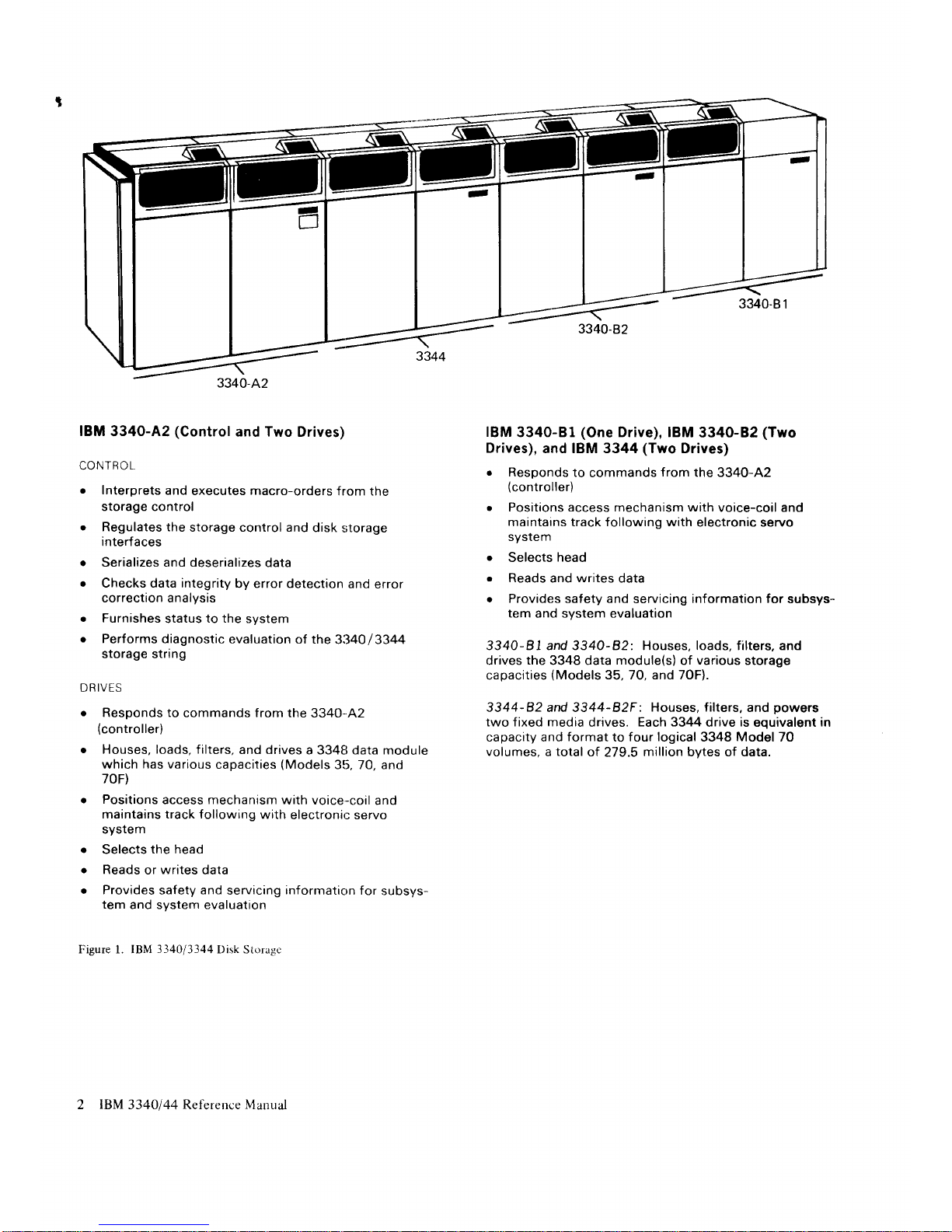
IBM
3340-A2
(Control
and Two
Drives)
CONTROL
.
Interprets
and
executes
macro-orders
from the
storage control
r
Regulates the
storage control and
disk
$torage
interfaces
o
Serializes and deserializes
data
r
Checks data integrity
by error detection
and
error
correction analysis
o
Furnishes
status
to the
system
o
Performs
diagnostic evaluation
of the
3:140/3344
storage stnng
DRIVES
o
Responds to
commands from the
3340-42
(controller)
o
Houses, loads, filters,
and drives
a 334t| data module
which has various
capacities
(Models
31i, 70, and
70F)
r
Positions
access mechanism
with voice-coil
and
maintains track following
with
electronir: servo
system
Selects
the head
Reads
or
writes
data
Provides
safety
and
servicing
information
for
subsys-
tem
and system evaluation
Figure l. IBM
3-140/3344
Disk Storagc
IBM
3340-8l
(One
Drive), IBM
3340-82
(Two
Drives),
and IBM 3344
(Two
Drives)
r
Responds
to
commands
from
the 3340-42
(controller)
r
Positions access mechanism with
voice-coil and
maintains track following with
electronic servo
system
r
Selects
head
r
Reads
and
writes
data
r
Provides safety and
servicing
information for
subsys-
tem
and system evaluation
3340-81 and 3340-82: Houses, loads, filters, and
drives
the
3348 data
module(s)
of
various
storage
capacities
(Models
35,
70, and 7OF).
3344-82 and 3344-B2F:
Houses, filters,
and
powers
two fixed media
drives.
Each 3344
drive
is
equivalent
in
capacity and
format
to four
logical
3348 Model 70
volumes, a total
of
279.5
million bvtes of data.
a
a
a
2
IBM
3340144 Reference Manual
Page 7

STORAGT]
CONTROL
DEVICES
'[he
followirlg
storage
control
clevices ciln accommo-
datc 31140
133,14
clisk
storiiP.o.
o
3lt30
Storagc Control
lvlodel 2.
o
Systcnr,l-170
Moclcls
l5lt and
l(rl{ llltc:p'1a1sd
Storage
(
lontrol ( ISC--).
r
Syr;tcm7/-170
Modcl
145
lSCl.
o
Sy:;tem,/370
Model
145 Storagc Cttntrol
Fr:ttnc
3345
Models 3,
4,
and 5.
o
Systcm,/370
Model
135 lntcgratc:cl Filc
Attlrch-
rnent
(lFiA).
SPECIAL
}'EATI-]RES
I'he 3-14(J
drsk
storage has
four special
lcaturers
'Ihe
Model A2 can
he'
supplied
rvith
the strirrg
switch and
thc
rcmotc l;witch.
All 3340
ntodels cau bc ordered
with Rotational
Positicln Sensing
and
Fixecl
I lcad
Storage.
Thc
3344
tiisk stclrage
has
no spccial
leatures.
iis
Rotational
Positi<>r.r
Sensing
is
standartl. Fixed
llead
Storage is available.
but
must
be tlrdercd
Lry nroclcl.
l'he 3344
l\{oclel
R2F contains
l'ixed
hcad storaqe
anti
the
Model
Il2 does
not.
String
Sn'itch
'Thc
string
:i'witch
fe atttrc
is installcd
on thc 3340-42
(controller)
'I'his
[e'ature
pcrrrtits
thc 3340
strins t<r
bc
dynamicully
sharecl
by two
slorage control
tlcvices
-I'he
fcaturc'
inclrrclcs
two
intcrlockccl
F-,na[rlc,/Dis:rhlc
switchcs alkrwing
the
strirrg
1o
bc
declicirtcd
to
crthe r
storalle control
ttr acc:cssihle
by
cach.
A re ulotc
contr()l
srvitch
pcnnitting
thc switclres
to
hc activatc<l
lrom a
l5li
or l6lt
Nlultipr<)ccssor
is also lrvailablc.
3340/3344
STORAGE
CONTROL
l'age ol
(i
Al.6- |
(r
I
()--l
Rcvrsccl M:rv 2('. l()76
Iiv
-l'Nl.:
(;N26-O.r2l{
AND
FEATURES
Rotational
Pnsition
Sensing
Thc
Rotatittnal
Position
Sensing
(RPS)
fcattlrc-
recluces
lhe channel
contrection
timc
requirecl
to
scarch for
a
given
recortl al'te
r thc
track
ancl hcad
have
treen
sclccted.
This
ferature
(optional
tltl the 33"10,
stanclard
<in the 3344)
disconnects
ther
drivc
from thc
channcl
anrl
pe
rmits
other channe
I operations
to
bc
rlerfornred
during
the
timc
requirccl
for the
spinclle
to [rring
the
rctluircd
rccortl
to the
re
rrd
z
writc hcatl.
Additi<lnal
cletails
on
RPS ancl
its associate
cl conr-
mancls
arc
fottncl
in thc
following
ptrblicati<lns:
c
Re.ferente
Mattutt/
f'or
Integraled
Stt;roge
C'ontrol.
Orclcr
No. CiA26-I62.0.
o Re.ft:rent'e
Manuol
for
-18-1
0-)
Storage
C'ontrol,
()rclcr
No. GA26-
1617.
F'ired
FIeads
1'hc 3340
lixccl
heacl
feature
pcnnits
use
ol thc
334t't-70F
data
rnodule
on
ar.ry
3340
drivc tl'rrt
has
[-reen
converted
for
fixed
hear-l
r.rsc. This
70-mcgabytc
cleta
mclilulc
contains
lixed
heads
in addititlu
ttl
tl.tc
rrormal
acccss
hcacls.
With
thcsc
l'ixed
heacls. 500
tl.rousancl
hytcs
tll st()rage
are
availablc
that
have ze
r<r
seek
timc.
Thc
fcrttttre
tlocs
not ittcrease
data
trroclttle
st(.)rage.
bccattse
an equivalent
ltllloLlnt
of storagu'
runctcr
thc
ntovit-tq
hclds
bcconrcs
inaccessiblc.
'I'hc
3344-R2I:
clual-dril'e
is also
cquippcd
with
fixed
he rd
st<lragc.
ln this
nl<lclcl,
both
3344
tJrivcs havc
I .004
milliotr
fryte s of
zero
seek
title
storallc.
This
fixed
hcad
storagc is
associatecl
tlnly
with thc
primary
adrlresses
on
c.tclt 3344
ilrirc
(sec
F-igurcs
2 antl
3).
fior
f rrrthcr elcttrils
on
the
I'irecl
he
ad Icatttrc
arld
its
r.rscl'rtlnt:ss [()
y(lur sl-oragc
rrpplication. c()lltact
\'otlr
f fJM
s;.rlt:s
rcprtsctttativc
()r
sec
lhc
[:i.r'etl
l]ettd
["eulrrrr
I
;.sr
rt
()uir]e.
()rdcr
No.
(iAl6-
l
632.
l.l+o/I1.1-+
Slontqc
(
otIit-ol
lttttl
I titlLttcs
Page 8

CONFIGURATIONS
'f
he various
configurations
of
3340/3]i44
disk
storage
arc
dividcrl
into
two
groups:
configurati<tns
using
only
3340
units,,
and
configurations
using
a combination
of
3340
and
3344
units.
These
attachmerrt
methods.
listed
by nrodel,
follow.
3340
STORAGE
WITHOUT
3344I
In some
System/370
models,
strings
ol'3330
ancl
3350
storage
devices
can
be uscd
in
addition
to the
3340s.
Model
115
(lISDDA)
Thc
Modcl
I 15 uses
the
Direct
Drive
lr,ttachment
(DDA)
for
storage
control.
Four
drives
can
be
attaclred:
a 3340-A2
dual
drive
with
control.
and
a
3340-82
(dual)
or B I
(single)
drive.
Model
125
(l25DDA)
The
Moclel
125 uses
the
DDA for
stormge
control
ancl
can
ail-ach
one string
of
up to
eight
332f0
drives.
Model 135
(IFA)
The
Model
135
uses
the Integrated
File
Attachment
(lFA)
for storagc
control.
Sixteen
drives,
two
strings.
a
3340 string
and
a string
of
either
3340
or
3333/3330
drivcs
can
be attached.
Models
145,
155-II,
158,
165-II,
and
l6S
(3330-2)
Models
145,
158,
and 168
(ISC)
Storage
control
for
the models
shown
irs
either
a
31330-2
or an
Integrated
Storagc
Control.
The
3830-2
and
each ISC
path
can
attach
up to
32 drives;
four
strings
of
3333/3330s,
3340s, or
3350s in
any
cornbi-
nation.
3340
/
3344
CONFIG
URATIONS
When
the
3344 is
used, neither
3333
/333O
nor
3350
drives can
be attached
to
the same
storage
conl.rol.
A
3344 requires
four
logical
addresses
for
each
drive.
only rhe 135,
145,
155-II, 158,
165-il,
and 168
support
the
3344 dual
drive.
Model
135
(IFA)
The
Model 135
Integratecl
File
Attachment
has
a
maximum
of
34 logical
addresses.
'fhis
allows
two
storage
strings
to
be attached:
a
3340 string
and a
3340/3344
string
(see
Figure 2).
Models
145,
155-II,
158, 165-II,
and 168
(3830-2)
Models 145,
158,
and 168
(ISC)
Sixty-four logical
addresses can
be used
by a
3U30-2
or ISC
path
when a3340/3344
configurarion
is
attached.
Two
strings
of 333O/3344s,
a 3340 string,
and a short
string
of four
3340 drives
can bc
attached.
Figure
3 shows
the maximum334O/3344
configura-
tion.
Only
strings
0 and 2 can incorporate
the
3344
units.
E,ach
drive has
the hexadecimal
addrcsses
assigned
relative
to
the storage
control
as shown.
4
tgll 3l+0,/.1.1
Rcfercncc
Manual
Page 9

02
1_9
Lq
1C
a3-
1l_
u-
1D
Drive 0 1
No,
String
1
3340-A2
3340-82
3340-82
Drive0
12345
No.
"
Primary Addresses
lrigure
2. IFA 334013344
Maximum Configuration
(Hexadecimal
Adclressing)
3340-82
Drive
No.
01
String
1
3340-A2
01
String
2
3340-A2
3340-82
Drive
No.
Drive
2
3
No.
String
3
3340-A2
3340-82
*
Primary
Addresses
Figure 3.
ISC or
3830-2 |\34013341
Maximum
Configuration
(Hexadecimal
Addressing)
07"
27
2F
37
02*
22
2A
n
19"
1D
39
so
17*
Tr
3B
3F
16*
G
3
3E
10*
20
n
30
11*
n
n
3
18
lts
1A
I
re
Cor.rfigurations
Page 10
P:rgc
ol'
(i,
\iifr- l o
t
(,
-l
Rcviscd
l\4rr1,
26. l()7(r
Uv
I-Nt,:
(lNl6-0l2l.i
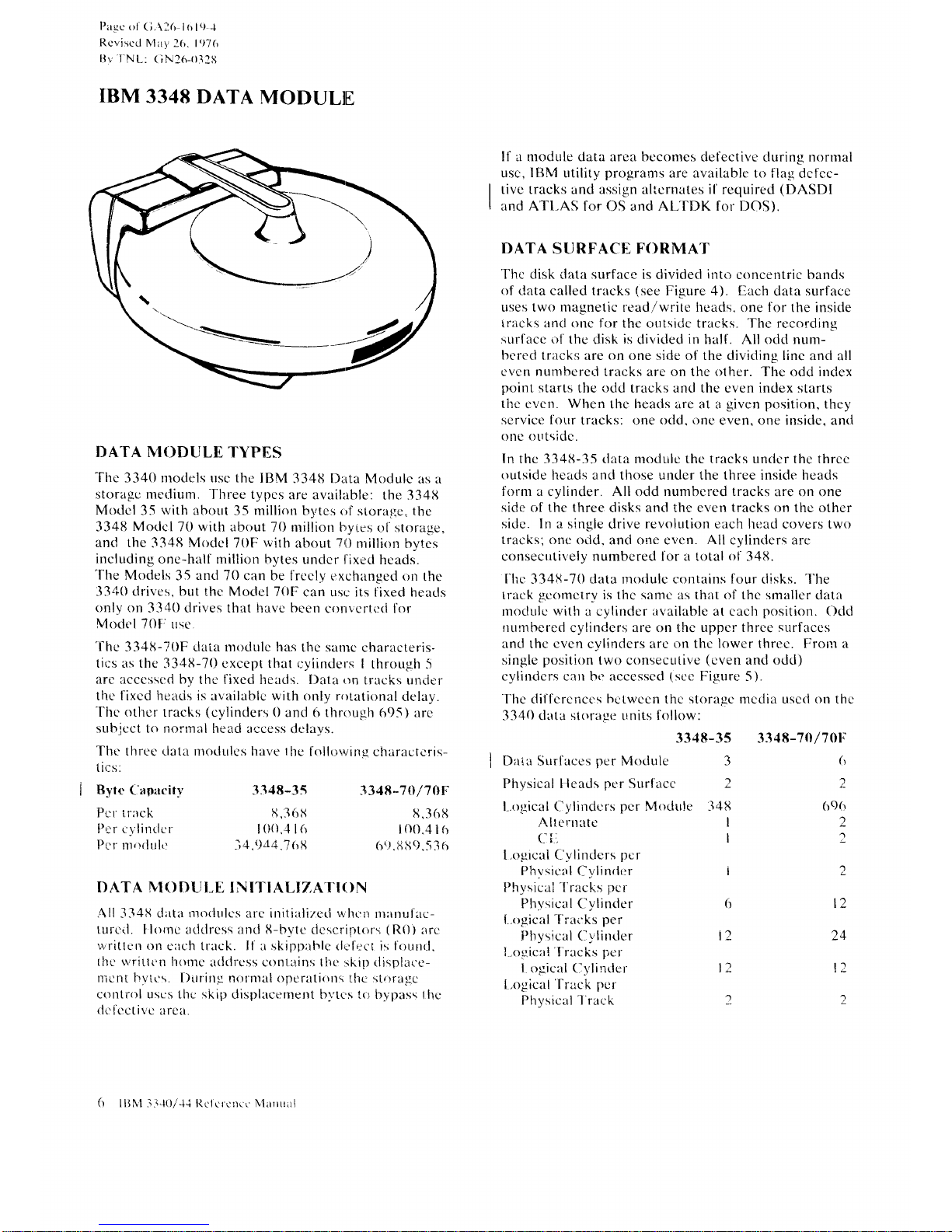
IBM
3348
DATA
MODULIE
DATA n*TODULE
TYPES
'fhe
3340 nroclels uscr thc
IBM
334u Data N,lodulc
as rr
storagc merJiurn.
-f
hree typcs
are avoililble:
the 334lJ
Modcl
35
with
aborrt 35 million
bytes of storaqe" the
33411
Moclcl
70 with about
70 milliorr t'ryies
ol'storage.
ancl the
334l;i
Model
70F
rvith
about
70
rrrillion
bytes
including
one-half million hytes
undcr ifixu-d
hcads.
'fhe
Moclt:ls
35
ancl
70 can be frccly
t:xchangecl
()n
the
-l3rtO clrivcs. but ther Nlclclel
7()[r
can usc its l'ixed heacls
()nlv
on
3-1,10 clrives that l.rave been
convcrtcd I'or
Moclel
70F rr-se
'Ihe
334tJ-lr0F data nrotlule has
tl.re sanrc
char:lcteris-
tir:s as the
3341{-70 cxcept that
r-:f
iinderrs
I thror-rgh
-5
arc acccsscd by
the I'ixed heads. [)ata
r.rn
tracks uncier
thc I'ixed heacis is ar,'ailablc with only rotational
delay.
-fl.rc
othcr
tracks
(cylinders
0 antl {i tlrr,rugh
695) are
suhje
ct to
norrnnl
lreacl access
cle
lays.
Thc thrce rlata
t ii:s:
Bytc
Captcitv
Pr:r imck
Per e
vlinder
Pcr rtt,lilul,:
nrodules have lbe
follt;vrins
charactcris-
DATA
I\T0DUI-T]
INITI ALIZATIII)N
All
l34l{
data rlorlrrlcs arc iniliiilizerl wlr,.lr
nt:rnulac-
trrrcil. llornc
aclclress anrl
l{-bvte
clcscri;rLors
(R0)
lrrc
wriItcrr on
crrch track. If l skipplhlc rl,.'lr:ct
i:i
fourrrl.
tlrc
q'rrttt'n
lrontc
atlclrcss conlains tlrc rtkin rlisplace-
lrcnt hvtc\. [)trrirtg n0rnral
()pcrllti(\ns
tl]e
sl,{)ra!_Ic
conlrol uses thc skip
displacenreltt br.'tc's 1o bypass
llrc
dcicctivc
arca.
Il'a mcrdule data
area bccomes defective cluring normal
usc,
IBN'l
utility
progranrs
are available to flag
dcfcc-
tivc tracks and assign alicrnates
if
required
(DASDI
and AII-AS for
OS
and AL'IDK for DOS).
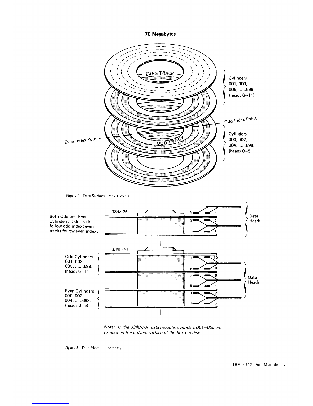
DATA
ST-JRFACE FORMAT
Thc disk data surface is
dividecl
into
concentric bands
of clata
called tracks
(see
Figure 4). [,ach
datir surface
uses two
rnagnetic
lcad/wr-ite heads. one for
the insicle
irac:ks ancl
one
l'or the clutsictre tracks.
'Ihc
rercording
surlacc o1 the
disk
is
clivicled
in
hall'. All odd num-
bcrecl
l.r;rcks are on one side ol'the divitling Iinc
and all
evern
nunrhere,-'l
trircks are on the o1her. The odd inclex
point
starts
the ocld trac:ks ancl the cven index starts
tire
evcn.
When
thc lreacls are at a
given positior.r,
they
scrvice four
tracks: one odd,
one:
even, one insicle. and
one otrtsiclc.
In
the 334lJ-35 tl:rta nr<ldulc the tracks unclcr the three
outside
heirds ancl those under the three insicle heads
form
a cylinder. All
odd numberrcd tracks
are on one
side of the three
disks arrcl the even
tracks
on the other
sidc. In a
single drive revolution each ht:acl covers tw<r
tracks; one
ocld. and one even.
All
cylinders are
consecrrtively numbered lor a total
of
34it.
I'hi:
-1341{-70
data rnodulc contair.rs four
cltsks. J'he
track
gcomctry
is thc samc as that of the smaller
data
rnoclulc with a cvlindcr irvailablc at cach
position.
Oclcl
numhcred
cylinclers are on thc
uppcr thrce surfaccs
ancl thc
cven
c5,linders are on thc
lower
threc. Fronr a
single
position
lwo
consecutivc
(cven
and odci)
cyliudcrs
can hc
accesscd
1sec
F'igure
5).
The' dii'fcrcricers
he
l-wccn thc storagc mcdia uscd on thc
3340
cluta
st()ritge
units follow:
3348-35 3348-70/70t,
Da(lr
Surfaccs
per
Mcidr"rle 3
(r
2
69(r
2
2
2
t2
24
l2
1
Phvsical lleads ner Surlacc
2
:r348-3s
ii,36l(
l(X).4 l(r
-''il.9d4.7()ll
3348--70/70F
I,368
l(x).416
6'). tt 39.5
3
()
l,.ogicui Cylindr:rs
pcr
A lt rrrr ate
Ci;
l
.ogrcal f-'1,1 inclcrs
pcr
Phvsic:lrl
L-ylindt:r
Physicrii'l'r;rcks
pcr
Plr-vsic:al
Cylincler
l.ogic:rl
-['rai:ks
per
I'hYsical
(--)'Iinder
| .ogicrl I racks
pcr
I ogical
(lvlintlcr
L.ogicnt lrack
pe
r
Physical
'l
rae k
Mocltrle :348
I
I
I
t)
l2
l2
1
(t
llJNl l"t-ll:)/-l.i ltclclcnce Nlanrr;rl
Page 11
r' l',"
i"
tr,
ta
\.
tt.
t'-\i-.-
i-\i_11_--:-=
=1;1-j,
---
\\
--
--=-__:-_---
./
\ -? ,./-
EVEN TRACK
70
Megabytes
Cylinders
001,003,
005,......699.
(heads
6-1
1
)
Even
lndex
Point
Figure
4.
Data
Surface'frack
l,avorrt
Odd
lndex
Point
)
.,,,nr.,,
\
000,002,
I
oo4,......698.
)
{rreaas
0-s)
Both
Odd
and
Even
Cylinders.
Odd tracks
fo!low
odd index;
even
tracks
follow
even
index.
l"*.
t
n*o'
Odd Cylinders
001,
003.
005,
.......699,
(heads
6-1
1
)
Even
Cylinders
000,002.
004,
......698.
(heads
0-5)
Note:
/n
he
3348-70F data ntodule,
cylinders 001-005
are
located
on the
bottom
surface of the bottont disk.
Figure
5. Data
Module
Ceornetrv
1o,,.
t
'*o'
IBM 3348 Data
Module
Page 12

FORMATS
RECORD
FORMAT
The basic
unit of information
recorded
by
the drive
is
a byte consisting
of eight
bits.
A
group
of bytes
separated
by a
special
gap
is called
an area.
Areas
are
combined
to make
a record,
the logical
unit
of inform-
ation.
A record
consists
of
count,
key, and
data areas.
Count Area
The
count area
contains
the location
of
a data record
on a
specific track
and defines
the
size of
tlhe key
and
data
areas of the record.
The
count
area is
written
when the
record is formatted
and is not
changed
until
the record is
reformatted.
Key
Area
Use
of
the key area is
at the
discretion
of the
program-
mer. When
used, the key
area of
the record
contains
the
primary
identification
of the
data
portion
of the
record
(such
as social
security number,
man number,
part
number).
Once the key
area is formatted,
the contents
(but
not
the length) may
be altered.
If the key
area
is altered,
the data area
of the record
must also
be rewritten.
Data
Area
The data
area contains
the information
identified
by
the
count and key
areas of the record.
Data informa-
tion is
organized
and arranged
by the
programmer.
The
length
of the data
area is
defined by
the count
area.
Once the data
area is formatted,
the
contents
(but
not
the length)
may be
altered. The
contents
of
the
data area may
be altered
without affecting
any
other
area in the record.
TRACK
FORMAT
All tracks
are initially formatted
beginning
at an index
point
(see
Figure
6).
Each
track has
the
same basic
format:
home
address, track
descriptor
record,
and one
or more data records.
The records.
and areas
within
the
records,
are separated
by
gaps.
Home Address
Each track
contains one home
address, which
defines
the
physical
location
of the track
(track
address)
and
the
condition of
the track. Home address
is the first
recorded area
following
an
index
point.
Specific commands
are used
for
writing and reading
a
home address
area: Write Home Address
and Read
Home
Address. Home
address
is
normally rewritten
to
flag the defective
track. Writing home
addresses is
usually done at
the
IBM
plant.
Track
Descriptor Record
(R0)
This
record is always
the first record on the track
following
the home
address area. In IBM
program-
ming
systems, the R0 count field of
the defective
track
provides
the address of the alternate track.
If it is
an
alternate track,
the
R0
count area
proyides
the
address
of
the defective track. An
8-byte
data field
is used to
store
the
number
of bytes remaining
on the track.
Specific commands, Write R0
and
Read
R0, are used
for
writing and reading the track
descriptor record.
Data Records
One
or more
data records may follow the track
descriptor record
(R0)
on a track. Record format
is
determined at the time the count, key, and
data areas
of the record are
originally written by execution of a
Format Write command.
The format of the record is
rewritten by
another Format Write command.
Data records, as
well as track descriptor records, can
be formatted with or without keys.
Generally, file
organization determines whether keys are
used.
RECORD OVERFLOW
The record overflow
function
provides
a
means
of
processing
logical records that exceed the capacity
of a
track. When using overflow records, the cylinder
boundarv limits the size of the record.
8
IBM
3340144
Reference Manual
Page 13

Equal length records : 8,535
(track
capacity)
C
+
KL + DL
(bytes/record)
Track : 8,535
>
where:
track
where:
C(overhead/record):
167 if KL
:
0
=242ifKL+0
KL:
Key length
DL: Data length
The number of
records
(n/
of different key
and data
lengths that can be
recorded on a track must
satisfy
the following equation
(the
standard R0 is already
accounted
for):
Records n
Ic
*
KL(i) + DL(i)
i:1
167ifKL:0
242Lt KL
+
O
TRACK
CAPACITY
The number of records that can be recorded on a
track
depends on the record size. The following
equation
can be used to determine the number of
equal
length records
per
track.
The home
address and
standard R0 space and skip defect are taken into
consideration.
When R0 is
not
standard, the
following
formula should
be used:
Records
=8,'706
>-
[KL(o)
+
DL(o)
+
C-4]
+
Track
n
where:
f,
trufil
+
DL(i)
+
cl
i:1
c:167
if
KL:0
c:242if
KL+0
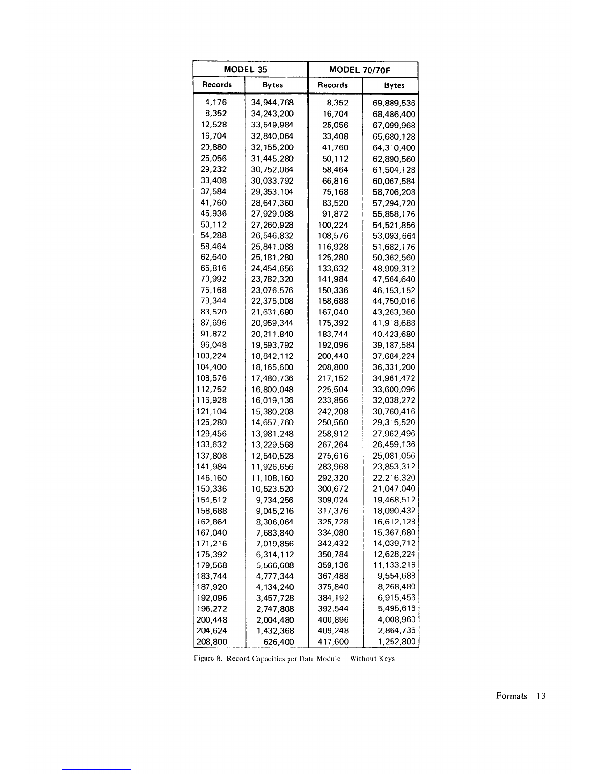
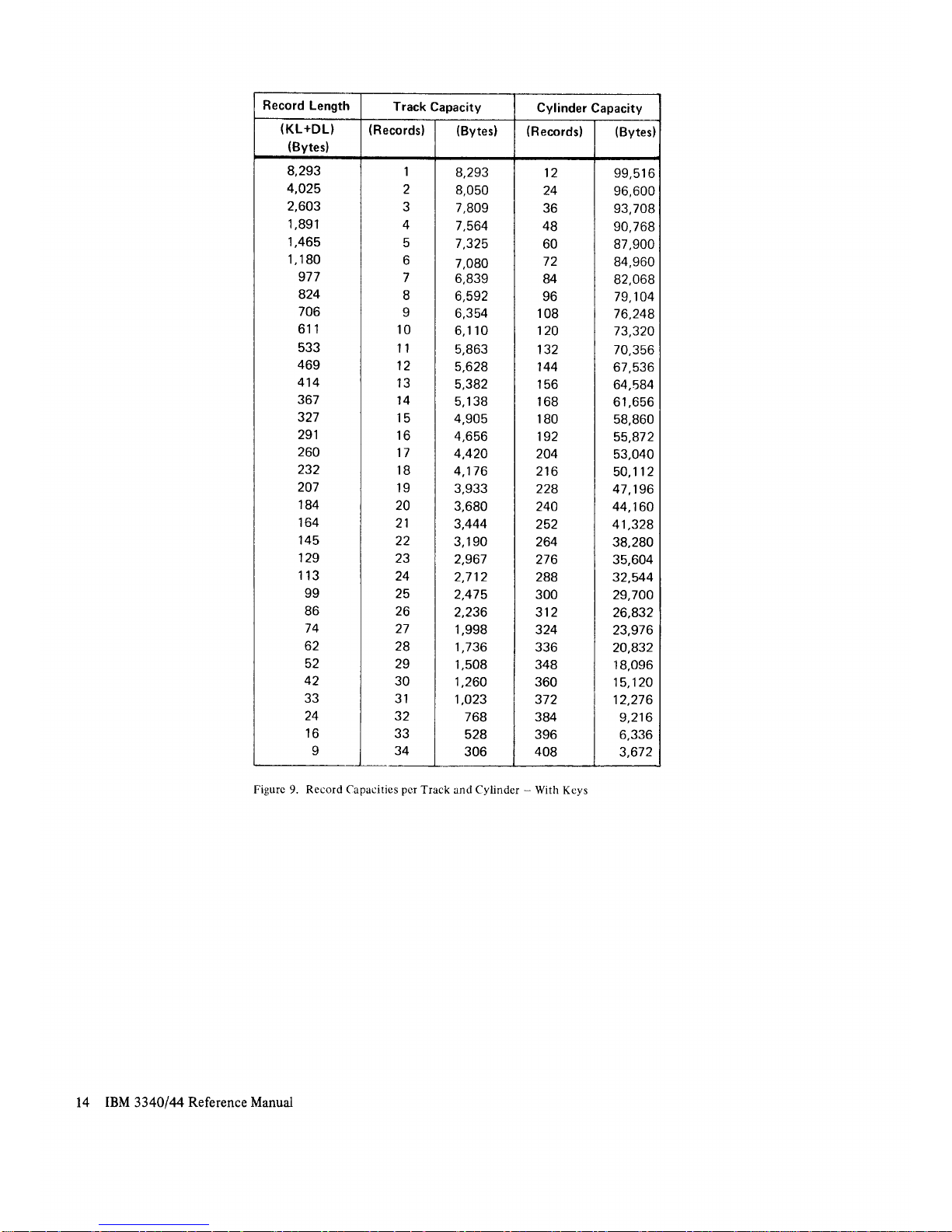
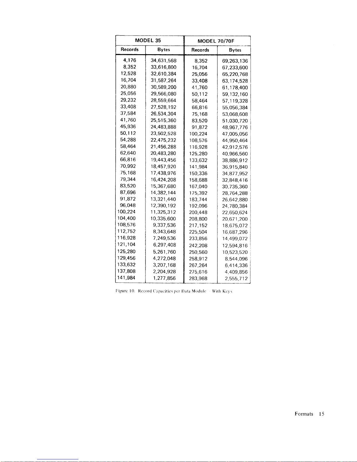
The tables shown in
Figures 7
through l0
give
maxi-
mum sizes of n equal-length
records on
a track where
n
is
all
possible
values.
Track, cylinder, and
data
module capacities
are
given in
both the
number of
bytes and the
number of
records.
There are tables
for records
without keys, and for
records with
keys. In all
tables, overhead for home
address and standard
record
zero
(KL
:
0,
DL : 8)
is
already
accounted
for.
C:
C_
Formats
9
Page 14

Track
Format
-.-
SD
I
PAIFICCI
HHI
DCB
(syrt.t
J
oata
G3 ( (svste./
/storus.
\Control)
1'Disk
to
]storus.
o'13:lJ"'
I
t0"".
I
I
or""
)
lt
t/
ffi
associated gap.
G2
f-
Ro
c.*,
I
ry
I
G2
I ndex
1\
Lrl
G2
G2
INDEX:
Inclicates
the beginning
of each
trar:k.
All
tracks
on
the
disk
surfar:e
are
synchronized
by
Index.
G1
(Gap
1): Separates
Index
and
Home
Address.
HOME
ADDRESS
SD
(Skip
Displacemer.rt):
Storage
control
indicators
for
skip
displacernent r:oncl
ition
of track.
PA
(Physical
r\dciress):
Storage
control
check for
verification.
Note:
Ihe
SD
artd
PA
bytes are internal
conventiorts
involv-
ing
only
the
storage control
and drive.
The
function
is
transparent
to the
using
systetn.
F
(Flag):
Defines
track condition
as follows:
Bit
0 - Skip
Displacement
Bits
1,2,4,
and 5
--
Unused.
Bits
6 and 7
00 = Normal
Track
01 = Alternate
Track
10=
I
11
|
Defective
Track
The
flag
byte
rray
be transferred
to
and fronn
the using
system. lt rs
tire
only flag
byte transferrable,
CC
(Cylinder
Number):
Specifies
the cylinder
numDer:
For
3348
35
0 to 347
For
3348-70
0 to 695
For
3348 7OF
0 to
695
(cylinders
1-5 fi>red
heads)
HH
(Track
Nurrrber):
Specifies
the readlwrite
track number
with
the selected
cylinder:
For
3348-35
0-1
1
For
3348-70
0-11
For
3348-70F
0-1
1
(cylinders
1-5
fixed
heads)
DCB
(Detection
Code
Bytes):
Generated
by
the 3340-,42
and used
for
error
detection.
l;igurc
6.
Record and
Track
lrornrat
l0
IBM
3340144 Reference
Manual
G2
t
Standard
R0
does
not
contain an R0
key
area
or
G2
(Gap
2):
Separates
home
address
and
R0
counr
area.
RECORD
ZERO
RO
COUNT
AREA
SD and
PA:
Same
as
Home
Address.
F
(Flag):
Defines
track condition
identifier
for
overflow
recoro
s.
Bits
0-2
*
Skip Displacement
Indicators.
Bits
3 and
5 - Unused,
bit 5 is
always
zero.
Bit 4 - When
on, indicates
that a logical
record
continues
on the next
track.
Bits
6 and 7
-
00 = Normal
Track
01
=
Alternate Track
10=
) |
ii=l
DefectiveTrack
CC
(Cylinder
Number):
Specif ies
the cylinder
number:
For
3348-35
0 to 347
For
3348-70
0 to
695
For
3348-70F
0 to 695
(cylinders
1-5 fixed
heads)
HH
(Track
Number): Specifies
the read/write
track
number
within
the selected
cvlinder.
For
3348-35
0-11
For
3348-70
0-1 1
For
3348-70F
0-1
1
(cylinders
1-5 fixed
heads)
R
(Record
Number):
Normally has a value
of Hex
00.
KL
(Key
Length):
Specifies
the number
of bytes in
the R0
key
area, from'0-255
bytes.
For
standard R0.
this
normally
has
a
value
of
Hex
00.
DL
(Data
Length):
Specifies
the
number
of
bytes in
the
R0
data
area,
from
1 to track
capacity.
For
standard R0,
tlris
normally
has a value
of
Hex
08.
DCB
(Detection
Code Bytes):
Generated
by
the 3340-42
and
used
tor
error detection.
Page 15
Track
Format
Disk
to
Storage
Controi
Data
I
)G3
)
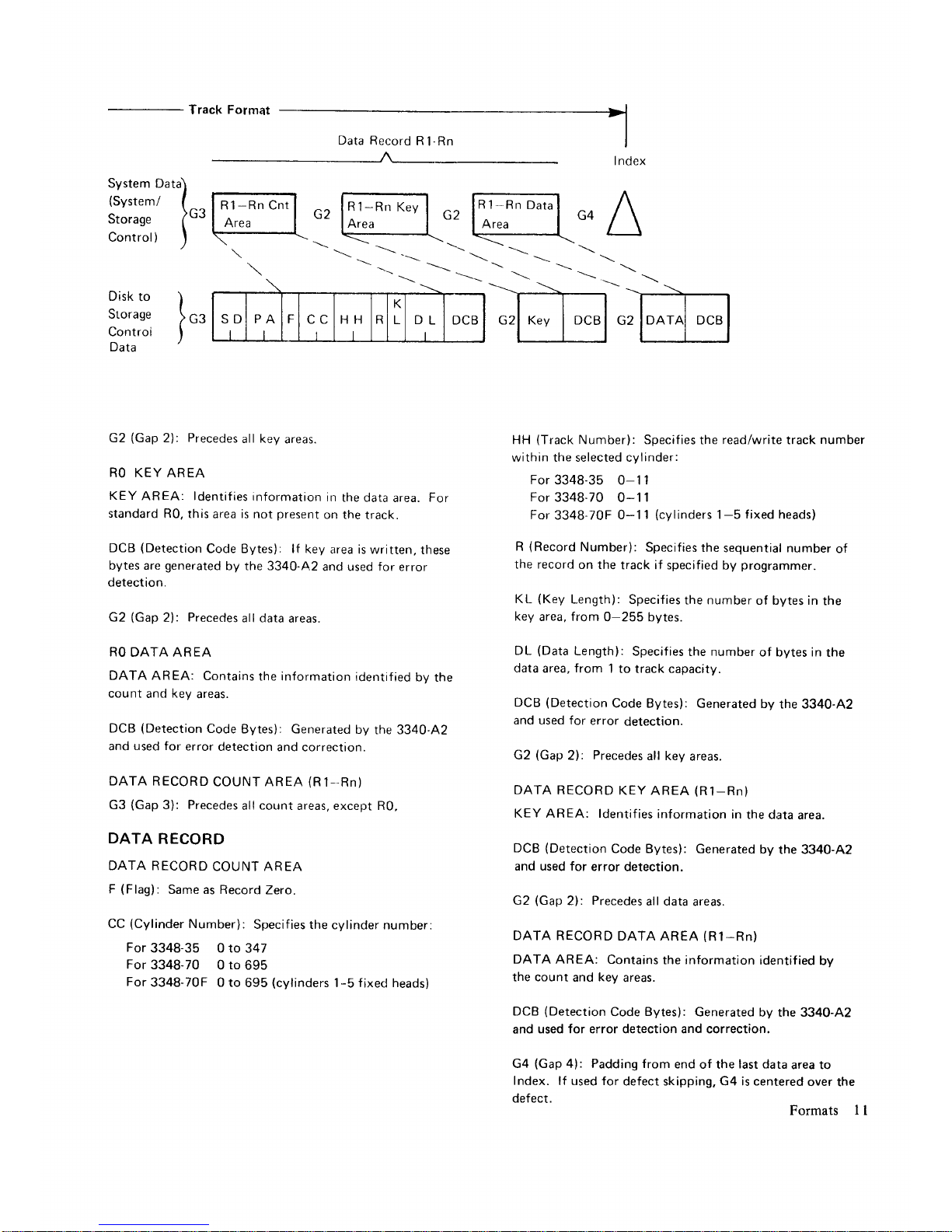
G2
(Gap
2):
Precedes
all key
areas.
RO KEY
AREA
KEY
AREA: ldentifies
information
in
the data
area.
For
standard
R0, this
area is not
present
on the
track.
DCB
(Detection
Code Bytes): lf
key area
is written,
these
bytes are
generated
by the 3340-42
and used for error
detection.
G2
(Gap
2):
Precedes
all data
areas.
RO
DATA AREA
DATA AREA:
Contains
the information
identified
bv
the
count
and
key
areas.
DCB
(Detection
Code
Bytes): Generated
by
the 3340-42
and
used for
error
detection
and correction.
DATA
RECORD
COUNT AREA
(R
1--Rn)
G3
(Gap
3):
Precedes
all
count
areas, except R0,
DATA
RECORD
DATA RECORD
COUNT AREA
F
(Flag):
Same as Record
Zero.
CC
(Cylinder
Number):
Specif ies
the cylinder number:
For
3348-35 0 to
347
For
3348-70 0 to
695
For
3348-70F 0 to
695
(cylinders
|
-5
fixed heads)
I ndex
HH
(Track
Number): Specifies
the
read/write
track
number
within the selected cylinder:
For
3348-35 0-11
For
3348-70
0-11
For
3348-70F
0-1
1
(cylinders
1-5
fixed
heads)
R
(Record
Number):
Specifies
the
sequential number
of
the record
on
the track if
specified by
programmer.
KL
(Key
Length):
Specifies
the number
of bytes in
the
key
area, from
0-255 bytes.
DL
(Data
Length):
Specifies
the number
of bytes in
the
data
area,
from
1 to track capacity.
DCB
(Detection
Code Bytes): Generated
by
the 3340-42
and used for
error
detection.
G2
(Gap
2):
Precedes
all key
areas.
DATA
RECORD
KEY
AREA
(R1-Rn)
KEY AREA: ldentif
ies information
in
the
d,ata area.
DCB
(Detection
Code Bytes): Generated
by
the 3340-42
and used for
error
detection.
G2
(Gap
2):
Precedes
all data
areas.
DATA RECORD
DATA AREA
(R1-Rn)
DATA AREA:
Contains
the information
identified
by
the count
and
key
areas.
DCB
(Detection
Code
Bytes):
Generated
by the 3340-42
and
used for error detection and correction.
G4
{Gap
4): Padding from
end
of the
last data
area to
Index.
lf used for
defect skipping, G4 is cent.ered
over the
defect.
Formats I I
Key DCB
Page 16

Record
Length
Track
Capacity
Cylinder Capacity
(DL)
(Bytes)
(Records)
(Bytes)
(Records)
(Bytes)
8,368
4,1
00
2,678
1,966
1,540
1,255
1,O52
899
781
686
608
544
489
442
442
366
335
307
282
259
239
220
204
188
174
tol
149
137
't27
't
17
108
99
91
84
76
70
63
57
51
46
41
36
.31
26
22
18
14
10
7
3
1
2
4
5
o
ti
q
10
l1
12
IJ
14
tc
to
17
18
't9
20
21
22
23
24
25
26
27
28
29
30
JI
32
JJ
34
35
36
JI
38
39
40
41
42
43
44
45
46
47
48
49
50
8,368
8,200
8,034
7,864
7,700
7,530
7,364
7,192
7,O29
6,860
6,688
6,528
6,357
6,1 88
6,030
5,856
5,695
5,526
5,358
5,1 80
5,019
4,840
4,692
4,512
4,350
4,186
4,023
3,836
3,683
3,510
3,348
3,1
68
3,003
2,856
2,660
2,520
2,331
2,166
1,989
1,840
1,68i
1,512
1,333
1,144
990
828
658
480
343
150
12
24
36
48
60
72
84
96
108
120
132
144
r56
168
180
192
204
216
228
240
252
264
276
288
300
312
324
336
348
360
372
384
396
408
420
432
444
456
468
480
492
504
516
528
540
552
564
576
588
600
100,416
98,400
96,408
94,368
92,400
90,360
88,368
86,304
84,348
82,320
80,256
78,336
76,284
74,256
72,360
70,272
68,340
66,312
64,296
62,1 60
60,228
58,080
56,304
54,144
52,200
50,232
48,276
46,O32
44,196
42,120
40,176
38,016
36,036
34,272
31,920
30,240
27,972
25,992
23,868
22,O80
20,'t72
't8,144
15.996
13,728
1 1,880
9,936
7,896
5,760
4,116
1,800
Figurc
7.
Rccord
(lapacities
per
Track and
('ylinder
-
Without Keys
12
IBM
3340/44
Reference Manual
Page 17
MODEL
35
MODEL
7OI7OF
Records
Bytes
Records
Bytes
4,176
8,352
12,528
16,704
20,880
25,056
29,232
33,408
37,584
41,760
45,936
50,112
54,288
58,464
62,640
66,816
70,992
75,1
68
79,344
83,520
87,696
91,872
96,048
100,224
104,400
108,576
1't2,752
116,928
121,104
125,280
129,456
133,632
137.808
14
t
,984
1 46,1
60
150,336
154,512
158.688
162,864
167,O40
171
,216
175,392
179,568
183,744
187,920
192,096
196,272
200,448
204,624
208,800
34,944,768
34,243,200
33,549,984
32,840,064
32,155,200
31,445,280
30,752,064
30,033,792
29.353,1
04
28,647,360
27,929,O88
27,260,928
26,546,832
25,841,O88
25,181,280
24,454,656
23,782,320
23,076,576
22,375,OO8
21,631,680
20,959,344
20,211,840
19,593,792
18,842,112
1
8.165,600
17,480,736
16,800,048
1 6,01 9, 1 36
15,380,208
14,657,760
13,981,248
13,229,568
12,540,528
1 1,926,656
1 1
,1
08,1 60
10,523,520
9,734,256
9,O45,216
8,306,064
7,683,840
7,019,856
6,314,112
5,566,608
4,777,344
4,134,240
3,457,728
2,747,808
2,OO4,480
1,432,368
626,400
8,352
16,704
25,056
33,408
41,760
50,112
58,464
66,816
75,'t68
83,520
91,872
100,224
108,576
1 16,928
125,280
133,632
141,984
150,336
158,688
167,O40
175,392
183,744
't92,096
200,448
208,800
217,152
225,504
233,856
242,208
250,560
258,912
267,264
275,616
283,968
292,320
300,672
309,024
3',t1,376
325,728
334,080
342,432
350,784
359,1
36
367,488
375,840
384,192
392,544
400,896
409,248
4't7,600
69,889,536
68.486,400
67,099,968
65,680,1 28
64,310,400
62,890,560
61,504,128
60,067,584
58,706,208
57,294,720
55.858,1 76
54,521,856
53,093,664
51,682,176
50,362,560
48,909.31 2
47,564,640
46,153,152
44,750,O16
43,263,360
41,918,688
40,423,680
39,187,584
37,684,224
36,331
,200
34,961,472
33,600,096
32,038,272
30,760,416
29,315,520
27,962,496
26,459,136
25,081,056
23,853,312
22,216,320
21,047,O40
19,468,512
18,090,432
16,612,128
15,367,680
14,O39,712
12,628,224
11,133,216
9,554,688
8,268,480
6,915,456
5,495,616
4,008,960
2,864,736
1,252,800
Figurc
8. Record
Capacities
per
Data
Module - Without Keys
Formats
l3
Page 18
Record
Length
Track
Capacity
Cylinder
Capacity
(KL+DL)
(Bytes)
(Records)
(Bytes) (Recordsl
(Bytes)
8,293
4,O25
2,603
1,891
1,465
't,180
977
824
706
611
533
469
414
367
327
291
260
232
207
184
164
145
129
113
99
86
74
62
52
42
33
24
'16
1
2
3
4
5
o
7
8
9
10
1',|
12
13
14
15
16
17
18
19
20
21
22
23
24
25
26
27
28
29
30
31
32
JJ
34
8,293
8,050
7,809
7,564
7,325
7.080
6,839
6,592
6,354
6,110
5,863
5,628
5,382
5,1 38
4,905
4,656
4,420
4,176
3,933
3,680
3,444
3,1 90
2,967
2,712
2,475
2,236
1,998
1,736
1,508
1,260
1,023
768
528
306
12
24
36
48
60
72
84
96
108
120
132
144
156
168
180
192
204
216
228
240
252
264
276
288
300
312
324
336
348
360
372
384
396
408
99,516
96,600
93,708
90,768
87,900
84,960
82,068
79,104
76,248
73,320
70,356
67,536
64,584
61,656
58,860
55,872
53,040
50,112
47,196
44,160
41,328
38,280
35,604
32,544
29,700
26,832
23,976
20,832
18,096
15,120
12,276
9,216
6,336
3.672
Figurc 9.
Re cord
Capacities
pcr
Track and Cylinder
-
With
Keys
14
IBM
3340144 Reference
Manual
Page 19
MODEL
35
MODEL
70/7OF
Records
Bytes
Records Bytes
4,176
8,352
12,528
16,704
20,880
25,056
29,232
33,408
37,584
4',t,760
45,936
50,112
54,288
58,464
62,640
oo,b
tb
70,992
75,1
68
79,344
83,520
87,696
91,872
96,048
100,224
104,400
108,576
112,752
1 16,928
121,104
125,280
129,456
133,632
137,808
141,984
34,631,568
33,616,800
32,610,384
31,587,264
30,589,200
29,566,080
28,559,664
27,528,192
26,534,304
25,515,360
24,483,888
23,502,528
22,475,232
21,456,288
20,483,280
19,443,456
18,457,920
17,438,976
16,424,208
15,367,680
14,382,144
't3,321,440
12,390,192
11
,325,312
10,335,600
9,337,536
8,343,648
7,249,536
6,297,408
5,261,760
4,272,048
3,207,168
2,204,928
1,277
,856
8,352
16,704
25,056
33,408
41,760
50,112
58,464
66,816
75,1
68
83,520
91,872
100,224
108,576
116,928
125,280
133,632
141,984
150,336
158,688
167,O40
175,392
183,7 44
r 92,096
200,448
208,800
217
,152
225,504
233,856
242,208
250,560
258,912
267,264
275,616
283,968
69,263,1 36
67,233,600
65,220,768
63,174,528
61
,1
78,400
59, 1 32,1
60
57,119,328
55,056,384
53,068,608
51,O30,120
48,56t,176
47,005,056
44,950,464
42,912,576
40,966,560
38,886,91 2
36,915,840
34,877,952
32,848,416
30,735,360
28,764,288
26,642,880
24,780,384
22,650,624
20,671,200
18,675,072
16,681
,296
14,499,072
12,594,816
10,523,520
8,544,096
6,41
4,336
4,409,856
2,555,712
Iigurc
10. Rccord
('upacitics
per
l)ata Modrrlc Witlt
Ke1,s
Formats
l5
Page 20

INPUT/
OUTPUT
OPERATIONS
This
section
contains
a
general
description
of l/
O
operations
used
with IBM
disk
storage
devices.
Detailed
information
about
the
central
processing
unit
and channel
program
control
of I/O
operations
is
foundin
IBM
System/370
Principles
o,f
Operation,
Order No.
GA22-7000.
DEVICE
SELECTION
AND
ADDRESSING
Device
Address
3340 DRIVES
Drive
addresses
are specified
in
the
I/O
instruction.
The
3340 address
is specified
in
bits 4,
5.,6, and
7 of
the
address
byte
(byte
3);
bit
3 is also
used
with
32
drive
addressing.
Any
drive address
from
hex
0 to F
can
be accepted.
Drives
0 to 7
are attached
to the first
con.troller
string
and drives
8 to F
on
the second
string.
If
a logical
connection
cannot
be made
because
the required
drive
is
offline,
Unit
Check
(Intervention
Required)
is
returned.
If multiple
selection
is detectecl
because
of
a
hardware
failure,
Unit Check
(Intervention
Required)
is returned.
Note:
Ifte drive
addresses
must
be wired
on a
logic
board
in the
drive
units.
3344
DRIVES
For
configurations r"rsing
3344
drives,
lhe device
addressing
is
modified
to handle
the multiple
logical
devices
on each spindle.
Bits 2
througJr
7
of byte 3
specify
the
logical
device
(a
maximum
of 64) and
bits 0 and I
the storage control
address. This
addressing
allows 3344
drives
on strings 0
and 2 only.
String 3 can have
only two 3340
units.,
one A2
and
one
B
(see
Figure
3). When
3344
drives
are attached
to
a storage control,
only 334013344
clevices can
be
controlled; 3330
or 3350
strings
cannot be
attached.
Seek Address
A specific
track
is selected
by sending
the
seek address
and
a Seek
command
to the
required
drive.
These
and
other commands
are described
in
the ISC
and
3830-2
reference
manuals.
Bytes 0 and
I are
unused,
bytes 2
and
3 ilre the
logical
cylinder
address,
and bytes
4 and
5 are
the logical
track address.
All seek
addresses
consist
of
six bvtes.
012345
OOCCHH
The
CCHH
part
of count areas
and home
addresses
normally
corresponds
to
bytes 2 through
5 of the
seek
address. The
physical
address
(PA)
bytes
in each
count area and
home
address indicate
physical
cylinder
and track addresses.
The PA
bytes are
written
by
the
storage control
and are
used for
seek verification.
When
the seek
argument
is received
by
the storage
control, it
is converted
into
physical
cylinder
and track
addresses
and sent
to the
selected
drive for
Seek
operations.
The
acceptable
seek addresses
for
the
3340/3344
devices
are:
ACCESS
AND DATA
TRANSFER
SPEED
The
total time required
for access
and data transfer
consists of access
motion, head
selection, rotational
delay, and data
transfer.
Access
Motion Time
Access motion
time is
the
time
required
to move
the
read,/write heads
to the correct
cylinder. If the
heads
are already at
the correct cylinder,
the access
time is
zero. Access
time is
also
zero
for data stored
under
fixed
heads when fixed
head models
are used.
If
the access mechanism
must move
to another
cylin-
der, a minimum
of 10 milliseconds
is required.
The
maximum access
movement is
50 milliseconds.
but the
average access
time is 25 milliseconds.
Head
Selection Time
The time required
to select the read/write
head
is
negligible.
Storage
Model
Data Tracks Alternate Tracks
cc
HH
cc HH
3348-35
a-347 0-'11
348
0- 11
3348-70
3348-70F
0-695 0-
11
696,697
0-
11
3344-82
3344.82F
0- 695
x4
0- 11 696,697
x4
0-11
l6
IBM
3340144
Reference
Manual
Page 21

Rotational Delay
Rotational
delay is the time required
for
the desired
record area to reach
the read/write
head so
that data
transfer can begin. This
time can range
from zero
to
almost a full revolution.
Half a revolution
(average
rotational delay) is
generally
used for
timing
purposes.
The maximum
and average rotational
delays for
3340
/
3344
drives
are:
Maximum rotational
delay : 20.24
milliseconds
Average rotational
delay : 10.12
milliseconds
Note:
Use of the Rotational Position
Sensing
featire
minimizes
the effect of rotational
delay
by
permitting
the drive to disconnect
from
the
channel,
thereby
allowing use of other
drives during
a
latency
period.
Data Transfer
Nominal read/write
rates for
the disk drives
are:
Bytes-per-second
:
885,000
Microseconds-per-byte
=
1.13
DATA
SECURITY AND PRIVACY
The 3340 and
3344
have a Read
Only function.
This
function,
in conjunction with
previous
methods
such as
File Protect
and Seek Verification,
offer a means
of
limiting
access to data areas
of the data module.
Read
Only Function
3340
MODELS
The Read
Only
function
provides
the means for
protecting
designated
data modules from
being
rewritten or erased.
Each
data module is equipped with
an inset in the
handle. The operator can change
the inset
position
before inserting the data module in
the drive.
Note: Iftis insert is only accessible
when the data
module is not on the drive
(see
the
"Operating
Instructions" sect ion).
When
the Read Only option is made,
any Write
command addressed to the drive is rejected.
Subse-
quent
sense Lnformation indicates
Command Reject
(byte
0,
bit 0) and Write Protect
(byte
1, bit
6).
3344 MODELS
In
the 3344
dual-drive
models,
the
Read Only func-
tion
is controlled
by a
switch
on the operator
panel
for
each
drive.
File Protection
Control of Write and
Seek
commands within a
pro-
gram
can be affected by the Set
File
Mask command.
A description
of the Set
File Mask
command is
given
in
the
ISC
and 3830-2
reference manuals.
By entering a
Set
File Mask, selected Write and
Seek
commands can be inhibited even though they appear
in
the
command
chain.
Seek
Verification
The 334O/3344 track
format includes two bytes in
each count area and home address
(physical
address,
PA) for seek verification. When a count area or home
address is
processed
during
Read,
Search, or Clock
operations, the bytes are compared
with the most
recent seek address. A non-compare
results in
termination of the operation at the end of the count area or
home address with channel end, device end, and unit
check. Seek check
is also indicated in the sense
information.
Input/OutputOperations 17
Page 22

ERROR
RECOVERY
PROCEDURE
Error
handling usually involves
storage
control
and
system-invoked
recovery actions.
These
recovery
actions
can
vary
depending
on
how
and
to what
system
the
3340/3344 is attached.
The
following topics
are associated
with recovery
actions involving
the 3830 Model2,
or ISC
(storage
controls),
and the
3340/3344:
o
Error
Correction Function
o
Error Condition Table
o
Errory Recovery
Action
ERROR
CORRECTION
FUNCTION
The
error correction function
(ECF)
is
part
of the
recovery
action
procedure.
The ECF
algorithms
and
the related
procedure
are fully described
in the
3830
Model 2 and ISC
reference manuals.
ERROR
CONDITION TABLE
The Error
Condition Table
(Figure
l1)
identifies unique
configurations of sense bits set
by the storage control
in sense bytes 0, 1, and 2. In
addition, it refers
to each
of these configurations in
a specific reco,yery
action to
be invoked by the system.
ERROR RECOVERY
ACTION
The
3340/3344 Recovery Action Table
(Figure
12)
specifies actions to be taken for error
conditions listed
in the
Error
Condition Table.
A necessary
part
of the
recovery action is the construction
of Restart
Channel
Command
Words
1 and
2.
Construction
of Restart CCWs
If Operation Incomplete
(byte
1,
bit 7)
is
set in the
sense information. it indicates
that an error or unusual
condition
occurred during a logical operation
after
data
transfer had been initiated. By constructing
Restart
Channel
Command Words,
the e,rror recovery
procedures
can correct the
unusual condition and
continue
the
operation
in
progress
from the
point
of
interruption
to the
normal ending
point.
RESTART CCW I
Restart CCW 1 is constructed as follows:
l. The
command code byte
is
provided
in sense
byte 3.
2. The data address is that of the interrupted
CCW,
plus
the count of that CCW, minus the residual
count in
the channel status
word
(CSW).
3.
The flags, except Program
Controlled
Interrupt
(PCI),
are
those of
the interrupted
CCW.
4. The
count is the residual count
in
the CSW. If
the residual
count
is zero, a count of one must
be
used. If a Write command
is
in
progress,
the data
address should specify a byte containing
'00'
.
If a Read command is in
progress,
turn on the
skip bit.
RESTART
CCW
2
Restart
CCW
2 is constructed as follows:
l.
The command code
is
provided
in
sense byte 3.
2.
The count
is
constructed
as follows:
a.
Fetch
the
count of the CCW designated by
CSW-8, and set
a
pointer
to this CCW.
b. Subtract the
restart displacement from the
count obtained
in
step
a. If this result is
positive,
go
to step
f; otherwise
go
to step c.
c. Check the
chain data flag of the CCW desig-
nated
by
the
pointer.
If the
flag is not
set,
go
to step e; otherwise
go
to step d.
d.
Advance the
pointer
to the
next non-Transfer
in Channel
(non-TIC)
CCW
in the data chain
and add the count of this CCW
to the counts
of all
preceding
non-TIC CCWs
in
the
data
chain.
Return to step b.
e. Truncation occurs. Set
the restart
CCW
2
count equal to 1. Go to step 3
and include the
skip bit
in
the
Restart CCW flags.
f.
Set
the Restart CCW
2 count equal to the
result of the subtraction
in
step b.
Go
to
Step 3.
l8
IBM 3340144
Reference
Manual
Page 23

3.
4.
The
flags
(except
PCI)
are
those of the
CCW
designated by the
pointer
in
Step
2. The
skip
bit
is also set if
Step 2e was
previously
executed.
The
data address is
that
of the
CCW designated
by
the
pointer
in
Step 2,
plus
the
count
of that
CCW, minus the Restart
CCW
count
generated
in
Step 2.
If another
Operation Incomplete
occurs
while execut-
ing
the
Restart
CCW,
a new Restart
CCW
may be
generated
from
the old
Restart
CCW.
Note: Be sure to
avoid
destroying the
old Restart
CCW before
generating
the new one.
Error Recovery
Procedure
19
Page 24

334013344
Error Condition Table
Byte
Bit
Name
General Description
I
Action Logged
0 0
Command
Reject
Progrermming
error
1 No
0 1 Intervention
Required
Drive
off
line, Not
Ready, CE Mode,
or data
module
incom.
patabi
ity
such
as
a 3348
70F
installed
on a drive
that does
not
have
the
Fixed Head
feature.
1
Yes
0 z
Bus
Out
Parity
Bus
Out
parity
error.
.J
Yes
0 Equipment
Check
Equipment
malfunction.
4
Yes
9
4
Data
Check
Data
check
in
home
address, count
area, or key
area;
or
uncorrectable
data check in
data area.
4
Yes
0
5
Overru n
Service
overrun
or
commano
overrun.
4
Yes
0 o
Track
Condition
Check
Non-home
address or
record 0 commands for
a defective
track
or any multitrack
commands switching
from
a
known
alternate
or defective
track.
6
No
0
6 Track
Condition
Check
Operation
Incomplete
Switching
from
alternate track
during overf
low
record
processing
or switching
to a defective track
during
overf I'rw record
processing.
I No
0
Seek Check
Seek incomplete
or
incorrect
physical
address
when
reading
home
address
or
count
area.
o
Yes
0
2
4
I
Data
Check
Correctable
Correr:table
data
check in a non-multitrack data
area or
the data
area of the
last
overf
low
segment.
7 Yes
0
2
1
4
I
7
Data
Check
Correctable
Operation
Incomplete
Correctable
data
check ir-r
data
area of overf
low
segment
is
not
the
last
segment.
8 Yes
0
2
1
0
4
1
1
o
Data
Check
Correctable
Operation Incomplete
Track
Condition
Check
Correctable
data
check in the data
area of an overflow
segment
(not
the last
segment) of an alternate track
8A
Yes
0
1
0
6
Command
Rejecl
write Inhibit
A
Wri
te command received
with
the selected
drive
in
the
write inhibit
state
1
No
1 I
Invalid
Track
Format
Track
capacity
exceeded.
2 No
1
2 End
of
Cylinder
Cylincler
boundary
detected
duringa
basic multitrack
operation.
10 No
1
1
2
1
End
of Cylinder
Operation Incomplete
Cylincler
boundary
detected
during a basic overftow
ooeral.ion.
11 No
4
No Record Found
Programming
error
or expected
programming
error
condition.
The
searched data
does not exist
on that
trac
k.
z
No
5 F il'e Protected
The
Sr-'ek command
or
Read/Search
multitrack
ooeration
violated
f ile mask.
l2 No
I
1
5
7
File Protected
Operation Incomplete
A
Reard
or
Write
Overflow
ooeration
violated f ile
mask.
13 No
2 3
Environmental
Data
Present
Statisttical usage/error log information is
present
J Yes
Figure
ll. Error
Condition'lable
20
IBM
3340144 Reference
Manual
Page 25

__
_:19f111"j't1r
Trl]i11
Action
Explanation
Print
message
1 for
operator
and/or
customer enqirreer
notification
2
Exit
witlr
programming
error
or unusual
condition indication
3
a.
o.
Repeat
the operation
one
time.
lf
the error
condition
persists, perform
Action
t.
4
a.
Repeat
the
operation.
b.
lf
the
error
condition
persists
after
ten
retries.
perform
Action 1
5
a.
lf
this is
a defective
track,
perform
Action
5A.
b.
Use address
of
defective
track
plus
1 in
a Seek commancl. The defective
track adclress
can
be for-rncl in
the
I D area of the record 0 count
area.
c. Resume
operation
after
searching
to desired
track
positron.
5A
a. Use
address of
alternate
track
in
a
Seek conrmand. The
alternate track
adclress
can be
founcl in
the
lD
area
of the
record
0
area.
b. Resume
operation
after searching
to desired
track
position.
6
a.
lssue
a
Recalibrate
comrrrand.
b. Seek
to
the original
address.
c.
Perform
Action
4.
7
a.
Perform
error
correction
function.
b.
Examine
bit 7 of the file mask. lf
this
bit
is
off,
go
to stel)
c. lf this bit
is on,
rcturn to user
with
indica,
tion that data has
been
corrected.
(User
is
operating
in
PCI
fetch
mode
and
mtrst,
therefore, suFrply
restart
recovery
action.)
Note:
Only applies
with
05/360.
c.
lf
the
user's
chain has not
been
completed, examine
the
next
non-TlC
command
in
the
user's
chain. lf bit
3 of this
command is
on
(count
area),
go
to step d.
lf bit is off
,
perform
Action
74.
Note: lf data
chaining is
indicated in
the interruptecl CCW,
the
prececling
tesr
/r{/sf
be
executecl
on the
first
non-TlC
CSW
after the
last
CCW in the
data chain.
d.
Continue
the
user's
chain by executing
the
following
CCW chain:
Seek
(same
as original)f
Set
File Mask
(same
as original)
Read
Home
Address
(skip
bit
on)
Search
lD Equal
(CCHHR
provided
in sense bytes 8-12)
Trc-
-8
TIC
(channel
status
word)
74.
Continue
the
user's
chain by executing
the
following
command chain:
Seek
(same
as original)t
Set
File Mask
(same
as
original)
Read
Home Address
(skip
bit
on)
Search
lD
Equal
(CCHHR
provided
in sense bytes
8-12)
Trc-
-8
Read
Count
(skip
bit on)
TIC
(channel
status word)
t Cylinder bytes
and
the high-order
head
byte
are obtainecl
frotn the user. The low-orcler
heacl
byte is obtainecl
from bits 3 through 7
of sense byte
6.
lrigurc
I 2. Recovcry
Aclion'fable
(
I ol 4)
Error Recovery Procedures
2l
Page 26

Action
l--'---------
i
I
Set
File
Mask
Set
Sector
Search lD
Equal
TIC-
8
Restart
CCW
2
TIC
33,Ol33/,4 Recovery Action Table
(continued)
Explanation
a.
Perform
error
correction
function.
b'
Examine
bit
7 of the
file
mask.
lf
this
bit
is
off,
go
to
step c. lf
this brt is
on,
return
to user
with indica-
tron
that
data has
been
cotrected.
(User
is
operating
in PCI
fetch
mode
and must
supply resta!-r
recovery
action.)
Note:
Only applies
with
OS/360.
c lrrcrement
the
seek argument
by
one.
Cylinder
bytes
and
the high-order
head
byte
are obtained
from
the
user.
The low-order
head
byte
is
obtainecl
from
bits
3 through
7
of
sense
bvte
6.
d.
Construct
Restart
CCW
2.
e.
complete
the interrupted
operation
and
continue
the user's
chain
(if
appropriate)
by executing
tne
followi
ng
command
chain.
Seek (argument
from
step
c)l
b.
o.
(_).
(same
as original)
(argunrent
0)
(record
1
)
(channel
status
word)
lVote"
lf
the modified
seek
argument
is
not
within
the user's
extent,
then toS
must
supply the
corr&t
seek
argument
before
issuin.g
the
seek. tf
that
is impossible,
then tOS
must
perform
Action
2,
Perform
error
correction furrction.
Examine
bit
7
of the file
mask.
lf
this
bit
is
off,
go
to step
c. lf
this bit is
on,return
to
user
with indica-
taon
that
data has
been
corrected.
(User
is
operating
in
pCl
fetch
mode
and
must
supply restart
recovery
action).
Note:
Only
applies
with
03/360.
Use
address
of the defective
track
plus
1 in
the Seek command.
Construct
Restart
CCW
2.
Complete
the
interrupted
o;reration
and continue
the user's
chain
(if
appropriate)
by executing
the
following
command
charn.
Seek
(argument
from
step
c) t
Set
File
Mask
(same
as original)
Set Sector
(argument
0)
Search lD
Equal
(recorcl
l)
Trc-
-8
Restart
CCW
2
TIC (channel
status
word)
Note:
lf
the modified
seek
izrgument
is not
within
the user's extent,
then IOS
must
supply
the corrrct
seek
argument
before
issuinlT the
seek. lf
that
is impossibte,
then tOS
must
perform
Action
2.
8A
t
Cvlinder
bytes
and the high-order
head
byte
are
obtained from
the user.
The
low-order
head
bvte is
obtained
from
bits 3 through
7 of
sense
bvte
6.
lrigure
12.
Rccovery
Action
Tablc
(2
of 4)
22
IBM
3340144
Reference
Manual
Page 27

33.0|33/,4
Recovery
Action Table
(continued)
Explanation
a.
lf
this
is
a
defective
track,
perform
Action
9A.
b.
Use
address of defective
track
plus
'!
in
a Seek command
and use
the
following
CCW chain
to
resume
ope rati
on.
Seek
Set
File
Mask
(same
as
original)
Set Sector
(argument
0)
Search lD
Equal
(record
1)
Trc-
-8
Restart
CCW
1
TIC
(channel
status
word)
Note: lf
the modifier
seek argument
is not
within the user's
extent,
then IOS must
supply the correct
seek argument
before
issuing
the
seek.
lf
that is
impossible,
then IOS
must
perform
Action
2,
a. Use address
of
alternate
track
in
Seek
command in
the
followinq
ccw chain
Seek
a'
Increment
the
cylinder
address
of the user's
seek argument
by one. Reset
the heacl
address.
b. Continue
the
operation
by executing
the
following
command
chain:
Seek
Set
File Mask
Set
Sector
Read
Home
Address
(skip
bit
On)
TIC
(channel
status
word
-
8)
Note:
lf the
modified
seek argument
is not
within the user'sextent.
then
tOS must
supply
the
correct
seek argument
before
issuing
the
seek.
lf
that
is
impossible,
then
tOS
must
perform
Action 2-
a.
Increment
the cylinder
address of
the user's
seek argument
by one. Reset
the head
address.
b.
Construct Restart
CCW 1.
c.
Complete
the interrupted
operation
and continue the user's
chain
(if
appropriate) by executing
rne
following
command
chain.
Set
File Mask
Set Sector
Search lD
Equal
Trc-
-8
Restart
CCW
1
TIC
Seek
Set
File
Mask
Set
Sector
(inhibit
seeks)
(argument
0)
(record
1)
(channel
status
word)
(argument
f
rom
step a)
(same
as original)
(argument
f
rom
step a)
(same
as original)
(argument
0)
Search
lD Equal
(record
1)
Trc-
-8
Restart
CCW
1
TIC
(channel
status word)
Note:
lf
the
tnodifiecl
seek arEtntent
is
not
within
the
user's
extent,
then
tOS
must
supply the correct
seek
argument before
issuing
the
seek.
lf
titat is itnpossible,
then IOS mu5t
perform
Action
2.
lrigurc
|2. Ilccovcrv
Aclion'I'utrlc
(3
til
4)
Error Recovery Procedures 23
Page 28

a
hr
Deternrine
if the interrupted
command is
Continue
the operation
by executing
the
334013344
Recovery Action
Table
(continued)
Explanation
a Seek. lf
yes,
go
to step b.
lf no,
perform
Action
12A.
following
command chain
:
(same
as original)t
(same
;rs orrginal)
(argurnent
0)
(skip
bit
on)
(channr:l
status word)
Note: lf
the
seek argLtment is not
within
the user's extent,
then
IOS
must
supply
thecorrect
seek
argLilrlent before issuing
the
seek.
lf
that is impossible,
then
IOS mustperform Action
2.
This is
a mr-rltitrack
operation.
Increment
the user's
seek argument
by one.
Continue
the
or)eration
by
e:recuting
the
following
command
chain:
Seek
Set
File
Mask
Set Sector
Read Hornc
Acidress
TIC
Seek
Set
File
Mask
Set Sector
(argument
from
step
a)
(same
ars original)
(argument
0)
12A'
I
Read Horne
Acldrt:ss
{skip
bit on)
TIC
(channel
status word-8)
Note: lf
thernodifiedseekargurnentisnotwithintheuser'sextent,thenlOsmustsupplythecorrfft
seek
arllurnertt
before
issuingr
the
seek.
lf
that is impossible,
then
IOS must
perform
Action 2.
a.
Lr.
c.
lncrernent
thc Lrser's
seek arqument
by one.
Construct Restart
CCW 1.
Cornplr:te the
intcrrupted
operation
and continue
the
user's
chain
following
command
charn:
appropriate)
by executing the
Seek
Set
File
Mask
Set Sector
(argum,:nt
f rom
step a)
(same
as
original)
(argumrant
0I
Search lD Equal
(record
1
)
Search lD Equal
(record
0)
Tlc*--g
Restart
CCW 1
TIC
(channel
status
word)
Note:
lf
the
ntoclified
seek
arEttnent is
not
within the user
seek argttntetlt before
issuittgl
the
seek.
lf
that
is irnpossible
s
extent, then IOS
must supply
the
corrtrt
then
IOS must
perform
Action
2.
Message
Messalle 1
(shoulcl
a.
Message
Code.
printed
on
all
p,ermanent
errors).
b.
Error
tvpe
(read,
write, or control).
c. Moclule designation, cylinder number,
and
head
number
(that
is, device address
and
seek address).
d. Cfrannel designation.
e.
Stalus and sense
bytes
to CPLJ
I
Cylinder
bytes and the
high-orde:r
head
byte
are obtained
from
the
user. The low-order
head byte
is
obtained
f ron
bits 3 through
7 of sense byte
6:.
I
rgtire I l. Ile eovt rr'
.,\e
lirrrr
{rrlrlr
14
ol
.1)
24
IBM
-1340i 44
Rel-erence
Manual
Page 29

"I'he
command set used
to
perform
operations
with
the
3340i3344 is as follorvs:
SENSE
COMMANDS
o
Sense
I/O Type
o
Serrse I/o
o
Read and Reset
Buffered Log
o
Test l/O
r
Read Diagnostic
Status
CONTROI, COMN,IANDS
o
No
Operation
o
Seek
o
Scek Cylinder
o
Seek
Heacl
o
Recalibrate
r
Restorc
(t:xecuted
as a No
Opcration)
o
Set
File N,Iask
o
Space Count
o
Set
Sector
e
Diagnostic [-oad
o
Diagnostic Write
o
Device Release
o
Di:vicc Reserve
For nrore
cletailcd
information
on the commancls, refer
to the
ISC
ancl 3tt30-2
reference
mernuals. Each of
the
comnrancls is briefly sunrmarized in thc
charts
on
the
f ollowing
pa!r.cs.
Pagc
,rl
(iA2(r'
l('
l9-'l
ll
i
Yill-
I l'.1 ii;i;,
I
ill
CHANNEL COMMANDS
READ COMMANDS
r
Read Data
e
Rcacl Key
and Data
o
Read
Courrt,
Key,
and Drta
o
Read Multiple
Count,
Kcv, and Data
r
Read l{ome
Address
o
Rc'ad
Count
o
Reacl
Initial
Progranr l.oad
o
Read Sector
o
Rcad Record Zero
WRITE
COMMANDS
o
Write Data
o
Writc Key
ancl
Data
o
Write Clount. Ke-y, irnd
Data
o
Write Home Adclress
o Write Record Zero
r
Write
Special Count.
Key, ancl
Data
o
Erase
SEARCH
COIlI]VIANDS
o
Search
lD Eclual
o
Search
Key L:qual
r
Search
l{omc Aclclress F,(lual
o
Serarch
Il) t{igh
o
Scarch
Key High
o
Scarch lD L:.qual or
l{igh
o
Search
Key Equal or
lliglt
(
ltlrrtrrel
(
r,111111.111i.
25
Page 30

Pagc
of
C,4,26- l6l9-.1
Revised
Mav
26, 1976
By
TNL:
C
N26-0321t
SENSE COMMANDS
Command
Code Function
Data Transferred
Across
Channel
Single
Track
Multi
track
Sense
l/Cr Type
E4
Transfers
seven bytes of sense data designating storage
control type, drive type, and data module
size
(3340
onlv).
7 bytes
of storage con-
trol
and drive
identifica-
tron.
Test l/O
00
Determines
status of
device
on
a channel. Generated
automatically
by channel
when status
information
reouired.
Note:
Test I
/O
is not a 3340 / 3344 command but
a
systern command similiar to start
l/O.
Command
code
(0000
0000) not written by
programmer.
One status byte.
Sense l/Ct
o4
Determines
cause of
last
unit check. Sense
data is
reset
after transfer.
24 bytes of sense
in-
f ormation.
Read and Reset
Buffered Log A4
Supplies usage or error
logging data
on
the addressed
drive.
Data is reset
uoon
transfer.
24 bytes
of
usage
or er-
ror logging data.
Diagnostir;
Sense
44
Determines
type of error(s)
found when running diag-
nostic test
(part
of
Diagnostic Write)
or
transfers
test to
system after a Diagnostic Load.
Note: lf command not
preceded
by DiagnosticWrite
or
Diagnostic
Load, 16 bytes of
data from error code
message
are transf erred.
1 6 bytes
of error code
message
or
51 2 bytes
of
test data.
26
31.10,/33.1'+
Referencc Manual
Page 31

Command
Code
Function
Data Transferred
Across
Channel
No
Operation
03 No action. Channel
End and
Device
End
are
presented
during
initial status.
None
Seek
07 1. Selects drive.
2.
Moves the access to the
cylinder
specified by the
seek
address.
3. Selects the
head
specified
by the
seek address.
Seek address
(six
bytes)
Seek Cylinder
OB
Space Count OF
When chained from a
Read,
Search,
Write
or
Space Count
command, this command
locates the start of the
next count
area
(including
R0),
spaces
over
the count area,
and ends
with Channel
End
and
Device
End in the
gap
before the
Key
area.
When
not chained,
Space
Count searches
for
index,
clocks
over
gap
1.
Home
address,
gap
2, and spaces
over
R0 count.
Operation ends in the
gap
following the
R0 count with
Channel
End
and Device
End.
Three bytes
used as
Key
Length
(one
byte)
and
Data
Length
(two
bytes)
for the
next command.
Recalibrate
13 Moves the
access
to
cylinder 0 and
select
head 0.
None
Restore
t7 No action. Zero
initial status
is followed
by
final status
of
Channel
End
and Device
End.
Seek
Head
1B Selects the head specified
by the seek
address.
Six address
bytes. Only
the
five low-order
bits
of
the sixth
byte are
used
for the seek
address.
Set
File Mask
1F Sets
file mask to indicate
permitted
Write, Seek,
and
diagnostic
commands.
One
byte of
file
mask
data.
Set
Sector
23
Used
on disconnected
command
chaining
channels
to
eliminate
the need for the channel
to
maintain
connection
with
the
storage
control while
waiting
for the selected
record to
reach
the
head.
Note:
lf the RPS
feature is
not installed
on
the addressed
3340,
this
command
returns Channel
End
and Device
End
together
in
final
status. No operation
is
performed
and track
orientation
is destroyed.
All 3344 units
have
RPS.
One
byte specifies
angular
track
position
(0-63)
CONTROL COMMANDS
Control
Commands
27
Page 32

Control
Gommands
(Continued)
Command
Code
Function
Data Transferred
Across
Channel
Diagnostic
Load
53
Transfers
the specified
512-byte
block
from
the
read-only
storage
to
the control
storage
buffer.
One byte
of control
information
addresses
one sector
on the
23FD.
Diagnostic
Write
73
Transfers
an inline
test
from
the main
storage
to srorage
control
and
executes
the
test.
A 16-byte
error code
message
is
stored
in
the
storage
control
buffer
area. A
subsequent
Diagnostic
Sense
command
transfers
the
error
code
message
to
main
storage;
requires
a
special
file
mask.
A
maximum
of
512
bytes.
Device
Release
94
Terminates
the reservation
of
the
addressed
device.
Only
available
f.r
two
channel
switch,
two
channel
switch
additional,
or string
svyitch
feature
machines.
Twenty-four
sense
bytes.
Device
Reserve
B4
Reserves
the
addressed
device
for
exclusive
,r" *i*
,.ilctil
is
made.
Only
available
for
two
channel
switch,
two channel
switch
additional,
or
string
switch feature
machines.
Twenty-four
sense
bytes.
28 IBM3340l4y'.
Reference
Manual
Page 33

READ COMMANDS
Command
Code
Function
Data
Read
Single
Track
Multitrack
Read lnitial
Program Load
(See
Note 1l
02
Recalibrates
to
cylinder
0 and head
0, searches
for
index
point,
and
reads
R1 data
from the
drive to
main
storage.
First data area
after
R0.
Read Data 06
86
Transfers
data area
of a
record
from
drive
to
main
storage.
First
data area after
address
marker
or
the data area
of the
record that was
chained from the
count
or key
area
of the
same
record.
Read
Key
and
Data
{See
Note
2)
OE 8E
Transfers key and data
areas of
a record
from drive
to
main storage.
First
key and data
area after
address
marker
or the key
and data
area that
was command
chained
from the
count area
of the
same
record.
Read Count 12
92
Transfers
next
count
area
(8
bytes)
from
the
drive
to main storage.
Next
record
count
area
or
first count
area after
R0.
Read Record
Zero
(ROl
(See
Note 3)
16
96
Transfers
R0
(count,
key,
and
data)
from
the
drive to
main
storage.
Record 0.
Note l: A Read
IPL command cannot be
prcceded
by
a
*t
File Mask command
in
the
sme
chain.
Note
2: lf
the
KL
quals
0, the command
is
executed
the sne
as a Red
Daa
command.
Note
3: When
chained
from a Search
HA
or Read
HA
command,
the Read
R0
command
is
executed
immediately
and does
not initiate
a earch
for
index
point.
Read
Commands
29
Page 34

Read
Commands
(Continued)
Command
Code
Function
Data
Read
Single
Track
Multi
track
Read
Home
Address
IA
9A
Transfers
five
bytes
(FCCHH)
to channel.
Transfers
count,
key,
and data
areas of
a record
from
drive
to
main
storage.
Byte
0
=
Flag
Byte
1
=
Cylinder
address
Byte
2
=
Cylinder
address
Byte3=0
Byte 4
=
Head
address
Read
Count,
Key,
and Data
1E
9E
Next
record
or first
record
after
R0.
Read
Sector
(See
Note
4)
22
Provides
one
byte
of angular
position
information
which
is used
by
a subsequent
Set Sector
command.
Whren
not
chained
from
a Read,
Write.
or
Search
CCW,
the
byte
transferred
is
the
angular
position
required
to
access
the last record
processed
on the
drive.
When
chained,
the
byte transferred
is
the
angular
position
of the
record
used
in
the
previous
CCW.
Read
Multiple
Count,
Key,
and
Data
(See
Note
5)
5E
Transfers
remaining
records
on
a track
to
the
channet.
In
use,
this
command
is
the
same
as a
series
of Read,
Count,
Key,
and
Data
commands.
Since
the number
of
byttes
is
unknown,
CCW
count
should
be larger
than
the
longest
track
length.
Use the
SlLl
bit to
suppress
incorrect
length
indication.
Starts
at count
f ield
of next
record
(except
ROl
Note
4:
Caures
loss
of orientation.
Note
5:
Command
Retry
works
only
on single
records,
so certain
types
of
errors
cannot
be
retried.
(The
Read
Multiple
Count,
Key,
and
Data
command
is
supported
on 3830-2,
lFA,
and tSt)
with
334O/33/M
configurations.
)
30 lBM334Ol44
Reference
Manual
Page 35

WRITE
COMMANDS
Note l: Same
as Write Count,
Key, and Data. Not
used
Note
4:
The CU
skips
writing
an
address
marker, sync
for
last
segment
of an overflow
record.
byte,
or
ECC.
Note
2: lf
file mask is
violated, set
Command
Reject.
Note 5:
Same
as
Write Count,
Key,
and
Data
except it
Must be
chained
from a successful
Search
lD
must be
chained
from
a Write HA
or a
Equal
or
Search
Key Equal command.
successful Search
HA
Equal command.
Note
3: lf
file mask is
violated, set
Command
Beiect.
Must be chained
from a successful Search
lD
Equal
command.
lf KL
:0,
operation
is
the same as Write
Data.
Command
Code
Function
Data Written
Single
Track
Multi-
track
Write Special
Count, Key, and
Data
(See
Note
'l
)
01
Same as Write Count,
Key, and
Data command except
a
1 is written in bit
4 of the
flag byte to
indicate
a
record overf
low
segment.
Same
as
Write
Count,
Key, and
Data.
Write
Data
(See
Note 2)
05
Changes
the data
area
of a
record.
Data
from
the sYstem.
Writes
the
number
of
bytes
specified
by the
DLDL bytes
of
the
count area
of the
same
record.
Write Key and
Data
(See
Note 3)
OD
Changes
the
key
and
data
areas of a
record.
Data
from the system.
Writes
the
number
of
bytes specified
by
the
KL and
DLDL
bytes of
the count area
of
the
same record.
Erase
(See
Note
4)
1'l Operates
exactly
like a
Write Count,
Key,
and
Data
command except
that data
from the
channel
is
not
written on the
track,
Bytes of 0s
to
end of
track.
Write Record
Zero
(R0)
(See
Note 5)
15
Writes count,
key,
and
data
areas
of
R0'
Flag byte
from
HA area.
CCHHRKLDLDL
from
system written
in
count area.
Key
and data
from
system.
Write Commands
3l
Page 36

Write
Commands
(Continued)
Command
Code
Function
Data
Written
Single
Track
Multitrack
Write
Home
Address
(HA)
(See
Note
6)
19
Writes
the
7-byte
(SDFCCHH)
home
address
area
on
the
selected
drive
and
track.
The
7-byte
(SDFCCHH)
home
address
area
transferred
from
the
system.
Write
Count,
Key
and Data
(See
Note
7)
1D
Writes
one
complete
record
on
the
selected
drive
and
track.
Count,
key,
and data
areas
of next
record
on
the
track.
Data for
the
areas
comes
from
the
system.
The
count
area
flag
byte, ECC,
and
gap
data
come from
storage
control.
Note
6: Must
be
chained
from
a
stisfied
Search
HA
(witn
the
CCW
count
area
of four
or more)
if defective
bit
(ftag
byte,
bit
il
is
off.
lf not
chained
from
a
stisfied
Sarch
HA,
defective
bit
must
be on.
Note
7: lf
file
mask
is violated,
et Command
Reject.
Must
be
chained
from
Write
R0;
Write
Count,
Key,
and
Data;
Erase;
a successful
Search
lD
Equal;
or
Search
Key
Equat
command.
After
last
Count,
Key,
and
Data
command
on
a
tack,
vwite
(h
tu index.
32
IBM
3340144
Reference
Manual
Page 37

Command
Code
Function
Data
Compared
Single
Track
Multitrack
Search
Key
Equal
(See
Note
'l
)
29
A9
Locates
a
key area
selected
bY
the
system.
The
key
area
bytes
from
the
selected
drive and
track
with data
from
the
system.
Search
lD
Equal
31
B1
Locates
a
count
area
selected
by
the system.
Five
bytes
(CCHHR)
of the
next count
area
from the
selected
drive
and
track
with CCHHR
from the
system.
Search
Home
Address
Equal
39
B9
Locates
a
home
address
area
selected
by
the
system.
Four
bytes
(CCHH)
of
home
address
area
from the selected
drive
and
track
with
CCHH
from the
system.
Search
Key
High
(See
Note 2)
49
c9
Locates
a
key area
selected
bY
the system.
The
key area
bytes
from
the selected
drive
and
track
with data
from the
system.
Search
lD
High
(See
Note 3)
51
D1
Locates a count area
selected
by
the system.
Five bytes
(CCHHR)
of the
next count
area
from
the
selected
drive and
track
with
CCHHR
from
the
system.
Search
Key
Equal
or
High
(See
Note
4)
69
E9
Locates
a
key
area
selected
bY
the system.
The
key area
bytes
from the
selected
drive
and
track
with
the key
area
from
the system.
Search
lD
Equal
or
High
(See
Note 5)
7'l
F'l
Locates
a
count
area
selected
by the
system.
Five
bytes
(CCHHR)
of
the
next
count
area
from the
selected
drive
and
track
with
CCHHR
from the
system.
SEARCH
COMMANDS
Note
|
:
The
key
area
compared
is the
key
area
of the
Note
3: Locates
any
tD
f rom the
track
that
is
higher
nextrecord(exctudingB0),unlesschainedfromthanthelDfromthesYstem.
a Read
Count
or Search
lD
commmd.
lf
Nolr-
4: Same
as Search
Key
Equal
except
the
key
area
chained
from a Count
operation,
dte
key
area
bcated
is equal
to
or
higher
than
the key area
searched
is in the
sme
record.
from
the
sYstem.
Note
2: Same
as Search
Key
Egual
except
the
key
area
Note
5:
Locates
the
lD
from the
track
iltat
is
equal
to
or
is located
in
any
key
area
on the
track
that is
hidter
than
the
lD
from the
system.
higher
than
the
key
area
from the
system.
Search
Commands
33
Page 38

SENSE
DATA
The
status
and
condition
of
the
3340/33441is
reported
inJhe
sense
bytes.
There
are
24
bytes
and
seven
different
formats,
G-6.
Four
formats,
l,
4,
5,
and
6
describe
the
disk
storage
condition.
The
remaining
three
formats,
0,
2,
and
3
are
associated
with
the
ltoragg
control.
Only
the
formats
dealing
rvith
rhe
3-340/3344
are
explained
in
this
publicatior:r.
Refer
to
the
ISC
and
3830-2
reference
manuals
for
lformats
0,
2,3,
and
a detailed
description
of
Unit
Status.
Some
sense
byte
formats
may
vary
for
the
clifferent
attachment
methods.
Therefore,
ine
SlqO/n44
user
should
also
order
companion
manuals
in
order
to
have
a
complete
set
of
sense
byte
information.
l.he
follow_
ing
manuals
are
recommended
for
System/l}70
Models
l15,125,
and
135
users:
o
IBM
System/37|
Model
II5
Functional
Characteristics,
Order
No.
GA33_l
5 10.
o
IBM
System/37|
Model
125
Functional
C
haracteristics,
Order
No.
GA33_
I
506.
o
IBM
System/37|
Modet
135
Functional
C
haracteristics,
Order
No.
GA33_3005.
Sense
Byte
Summary
In
all
the
formats,
the
first
eight
bytes,
0-7,
give
high-level
information
conceiningstatus
and
condi_
tion.
Sense
byte
7 identifies
the
format
in
which
the
remaining
bytes,
8 through
24,
are
arrayed:
r Bits
0
3
=
The
furrnat
array
of
bytes
g*24
0
1
2
3
Format
0
0
0
0
0
1
1
1
0
0
0
1
1
0
1
0
1
4
5
b
7
r Bits
4-,7
=
Define
a messaqe
Byte
Each-of
the formats
1,
4,
5,
and
6
(including
the
possible
messages)
is
summarized
in
the
charts
on
the
following
pages.
4
5
6 7
Message
0
I
0
1
0
101
0
F
34
IBM334Ol44
Reference
Manual
Page 39

Prge
ol
CiA26- l6l9--1
Rcvised
Mav
26, 1976
By
I NL:
CiN2(r-012t
3340/3344
SENSE
BYTE 0 throush 7 SUMMARY
Bit 0
1 2 3
4
5
6
7
--t
- -l
Byte 0
Command
Reject
lntervention Required
Channel
Bus Out
Parity
Equipment
Check
Data Check Overrun
Track j Seek
Condition
lCheck
Check
I
Byte
1
Permanent
Error*
Invalid
Track
Format
End
of
Cylinder
Not
Used
No Record
Found
File
Protected
Write
iOperation
Inhibited
llncomplete
l(See
Bvte
Byte 2
RPS
Present
Correctable
Data Error
Not Used Environ-
mental
Data
Pre-
sent
3344
Drive
Data Storase
T.ype
i
-r-]--
l
3sMB |
,o*,
I
Data
r\4o-
|
oata,r"
|
*?l#'n
oure I oute
,;;;:
|
",
rio
I
f."ifi?
I
'010'
I
Byte 3
Restart
Restart command
(provided
onlv
when byte
1, bit 7
is
on)
'06'
:
Read ooeration;
'05'
:
Write operation
Byte
4
3340
Drive
ldentif icatiorr
Drive A
Drive B Drive C
Drive
D
Drive
E
Drive
F
Drive G
Drive
H
Byte 4
3344
Drive
ldentif ication
Controller
Address Bits
z 1
Not Used Not
Used
Not Used
Phvsical
Drive
Address
Bit4
|
aitz
i
Bitl
_t__l_
Byte
5**
Cylinder
Address
Low-order
Logical
Cylinder
Address
128164|32IroI8I4I2|I
Byte 6*t
Cylinder
/'T'rack
Address
Not Used
High-order Logical
Cylinder
Address
512125612048***
Logical
Head
Address
8
+ 2
Byte 7
Format/
Message
Format
Message
Code
*Set
by
Error Recovery
Procedures.
**lf
seek check
active
(byte
0, bit
7), bytes 5 and 6 contain
the
last
seek
***CE
<;ylinders
posted
as
2800
through 2804
which results
in bits
1 and
3
These
are added
together
to equal
the
number
of
the CE cylinder.
argument
(address)
issued
to
the device.
being set,
plus
the
additional
bits
in byte 5.
Scnse
Data
35
Page 40

[)rgc
of
GA26-1619-:1
I{cvise
d lllrr1-
26.
l()7(r
Br.''l
NL:
(;N26-0l2li
3340
FORMAT
1 SENSIT BYTE
SUMMARY
,B;i;t
__----F;nlrotter
iDevic,r
io,iu"
--Tnead
lonrin" iot
lar.u
lseet
comptl
l3:l::^ icheck IIJ::l:'"" lctreck lyJr: I iAttention i ]3::n3":::'l
lstatus I
lcrrect<
!
jorect
I I I lPadcompr
I
i---..-.-_-r_--.-'-__|__-.'-.T--t
lByte
9
IDM
JSector
lMotor
at
lAir/Belt lyvritg lFixed
Head
lDara
Mo-
lData
Mo-
|
lChecks lloaded lCompare lSpeed lSwitch lEnable lData
N/lo-
lOule ldule i
lStattrs
lSwitch lCheck lSwitch llatched I ldule lSize
2
lSize
1
I
It,..^r^r I l, ---,,--' | | ln,--
"
1 rn rr,- I or rr' I
lChecks lloaded lCompare lSpeed lSwitch
lEnable
lData
N/lo-
ldule
jdule
i
lStattrs
lSwitch lCheck lSwitch llatched I ldule lSize
2
lSize
1
I
Larched
i llatched
I
I lSize
+
l-
zo rvu
-35
Mb
I
L
_
+
__+__
r____-,_,_f_
l_
_
+___-__
l
_____+____-
iByte
10
IDM
Size
lData
joata
loata lCheck lovt
Seo.
lBias lodd I
IDM
Sequc'nce
lCheck
lModule
lModule lModule llatch
lCheck
lDisable
lPhysical
I
l!,:t-.1
-- -- t ---- -L*qt
i.*:l
I --]Latch
1
1
- -[g'"13-1--ft*r"-l---1l*
1
i_
___ __ ___1______, --+
f______
__j
+
__ _t __ ___
+
layt"
r 1
lorive lor E;,.--]DM IDM
-F
B"[--p;;s;-lvro,o'
lload
Switch
lStart lPreserrt
jLocked
lUnloaded lloaded lSwitch lHome lSpeed
ll'l'"1 _ _ F_YII_ _
l_s*'rl
l9ryr{ llyr9t _lswrtch _i___ | lsw
tcrr
Fr*it-
----J*..,,r'o'"
lcapabte/ [r*"
__*--1,".*
-lR;;d^r/..*la;";.r
tnr,*
iwn,u
l---r
_-l
iLcr(wrrT lLorurra lLoLUrr
|
| |
i
-.---_-,..---+
+______
,_+
I
-- -! __ ---+
I
Drive
loru lcouer lorrl lolt lRir/aett lcarriage lMotor
at
I
lBvte
15*
i
irll^i.^i, .r.,u^"" I
Control Interface
Tag Bus
(at
time
error
was detected).
I
(Valid
only
for
message
codes
1, 3, 5, 6, 7, 8, and
9")
lTag
Bus
i
ler*
i6
-Jn.""*--lo;h;;alil;oir
F'.*
la;;--[-"-*
-[c".*r
iAccess
iTrnre
Out
lCheck
lTrack
ChecklCrossing
llatch
lMode
Latch
llatch
jeyte
tZ
jvtuttipte jCapable/
lwr,t"
jrnoer
lRead/Write lControl
iwrite
lwrrte
lRead
/Write
]Head lEnabl,:
lOverrun
lCheck lWrite lCheck lTransition
jCurrent
jSaf ety
lSelect lCheck I ] llnterlock ] iCheck lDurins
I lcheei____
l_
I _ _L
]ggl_l__r_
lry:ttl_
lByte
13*
]
Contrrf,l Interface Bus
Out
I
e xpected
Drrve
Status
lControl
lrterface
I
(for
messaqe code
C).
i
Data valid
for message
codes
lBus
Out
I I
1, 3, 5, 6,
7,
8,
and 9.
tl
lPyt: lll . ,
i
aontrot Interface
Bus ln
(at
time error
was detected).
iLonlrol
lrrlerrace
I
(Valid
only for
message
codes
1, 3, 5, 6,
7,
8, and
9.)
iels
ln
I __
iByte
15*
i -^^+-^r r-+^-{^^.- T-^ o..^ /^+ +i-^ ^.-^-.^,^^ i^+^^+^-r\
s*';oir
1i'.*
Track
Check
lCrossing
ch iMode
Latch
ilatch
jAccess
lStatus
f---
- -
lBvte
17
iController
lstatusluheck.iillllil
F*;; lFLo - lN;plo--IGRDES ]o.-- lw,*-
-lvr"*;__-Fle-c
-i
IController
lCheck llnput lCheck lCounter lData lCheck lCheck iZero ]
[,hl:!:
_+
]!l::l:
__
i_
_ __
l9lT-
__lg"e!___L
,_
L_ lq"'"e'"'j
l
inytets
I
I
i | |
i
i*:::l::,,;:*" I
Unusecl I unuseo
I
unuseo
I
unuseo
I
..dec
Error condition
(bits
4
tlirouqh 7)
lO
,li
l
t
-------- - -
-;-------]_-
+--+----+
iRwfe 19 lSpt R/\A/ lRpqervpd iReqenrcd lRpqerrrpd I ll o Gai. l-- Tfl""d-fl"* l
tv'_::a::
_:"
"'-
_f____ _- _
]__
,a;;".""" *;;"*"
l
iByte
19
lSet
R/W
lReserved lReserved lReserved I lLo
Gain
1
lFixe
lstatrslonlllllErrorliFeaturei
I l1.:"Bu,"J)l I | _i_____i
___i_
1_____j
I
---------
-
t
------
T
i
lBvte
20
lControl lControl lDrive
jDevice
lControl ll
Wrrte
lDevrce lDevtct: i
itnier+ace
llnturfu"*
llnterface
Iselection iBus
In
llnterface lFailrre lBus
out
lr.g i
evice
]D
evict--
|
us Out
,Tag In
arrty ChecklParrty
v
'I
_
t:l'::l
i
-t-^
I
'T''--'-
lLo
Gain
I lFixed
Hear
lError
I iFeature
rli
- --- --+
---+ -
+
r
--,----L.1..-'
rli
____l.,rllyr!lg*-co_1_"
_
_ l
*
These
l)ytes are also
valrrl for message
code 2 when byte
18
equals
1, 3, 5, 6, or E.
Note:
A,
B. C, and D
ref
er to bytes; on the f otlowing
page.
Page 41

Pag,.:
ol
(l,\2{,
l6
!Li-+
Rcvisctl !lal
16. l(r?(r
Llv lNL:
(;Nl(' (!Jlti
A tt
busy
(bit
13
on), Search
Sectoi-is
in
progress.
lf
set
read/write is
on
(byte
19,
brt 0
:
1),
byte 8
is:
llo
i
- -
12
l:
',0
'---5
'u
-i,
ljController
jDrive
lnter'
lDrrve
Ctreck
lReati/Write
lOn
Li'r" ilWrite
Sense
llndex
Mark
lAt;trve
i
l
lcnecl if
ace cfreck
i
io',u"i<
i
,
I
iTl,r,:r
B Wrtfr seek
c;heck on
(byte
0, bit 7), bytes 13
and 14 indicate:
lC
tf
seet check is on
{byte
O bit 7) and format 1
rnessage
A,
then bytes 20 and 2l
indicate
lo
i''
-i,-I' E- lo
l-11-l"li
I
Present
Segk
Address
')')
| 14
i0
i
I
Logrcal Head Address
lqizi
l.
I
i
1
li
Ct
lUnuscri
iJ
iReDet,t've
cornmaric overruns
orl G i operirtrorrs.
|l
r'-T
|
1 jit'io fag valro on read/write
operation.
I
I
lL3usy
rnrssrnq
after seek
staft
issued.
I r r
i--
|.jNon<-lrnraitlrc}reckenrjonread/Wr|teorECU
1t ,A
i I
operal
rurrs
I
r'
'
I
I i
3
I
No
response
l'ronr drrve
on
control
operation.
I
A Urrr-rsed
D Mi,:noprogriirn
efror
messages
tsense
rryre 18,
trrts 4 trrroir3ii 7).
lr
4
j1-irrre
out waitirrg f or index
or
actrvLj Lrlck
r
C Unuseci
1
--
I
b
:L(;(.
l,irru',u.r,e
.;rreci<
I
tl
_.t-.t1rt.st:d
tl
6
iVlultrr.,le
()r
no conr,ruller selei:te,J.
I
I
rUnuserl.
l-
7
iPresrlectiorr
check.
I
f
Attentrorr check.
L..
Scttsr'
| )lrll
Page 42

l)agc
ol
(i.,\,1,6-
|
(r
I
9-.1
l(cviserl
'rvlIlv
2(r.
I97(r
Uv
-[
N L:
(;N26-0321t
3344 FORMAT
I
SENSE BYTE
ISUMMARY
Latched
arget
elocrtv
oTor aI
otor
at
u
rrent
ontrol
lWrite lwrite
Exoected Drive
Status
Data valid for message
codes
1.
3, 5. 6. 7. 8. and 9.
HDA
Sequence
Latch 4
Transition
nte
Data ECC Hdwe
4-tldition
Ibits
Unused
lDevic,a lDrive lRead lOnline IHDA ll
llnterf
ace
lCheck lWrite I lAttention I
lcheck. llchecklll
1s"",". fv"n"'.r ln"
s*i."r'
ffi
-|F"=d
F1"Jl
lCompare lSpeed llatched lEnable lH
DA
lt
lCheck. lSwitch I I ltnstatted I
lllatchedllll
-IH-DA
--|HDA
-]nDA --|HDA
s"+-f"n*
I
lSequence lSequence lSequence lCheck lH
DA
I
lLatch 4 llatch
2
lLatcrr t lLatcn lRecycte ]
t,"d
-li;*s--
--li'..k -m-]i
lBand ]Velocity lCrossing I lSwitch I
lPatternlllll
l-. r,t,r"
l-ffi
o"H.
---Fc""i," -]i
lEnabl,e louetrrn lcnect ll
write
lcrrect< I
lcheck,
lllcheckil,
L_
__,-L
___1, _ __
l_L
L
Control Interface
Bus
Out
I
Expected D
(for
messase
code C).
|
""t",:i't:::
;
-_--*-.
**"
;;;;"
",,",
-.*",*"*
_ ___*_Y1onrv
for message
codes
1'
3' 5' 6' 7'
8'111i
Control Interface Tag
Bus
(at
time
error
was
detected)
(Valid
only for
message
codes 1, 3, 5, 6, 7,
8,
and
9.)
_"To**n.",
ls*'"-[n"*- ls**
-|L,n"*
l,
lCheck: lOtt
rract
lvooe
Latcn
lLatcrr
lvooe
t-atcr'
lt
-1
_--l----l--
I-
f f
lrtr"
eLo
-lsER;f
G.p
C*I[w'* Data
]Monitor lr
_l'*,,
__
lcnecr
pheck
lcheck
l9lg9* I
-l*,*"
l;*
[",*
--T--
I i | |
codedErrorcon
tttl
-fu"d-lu"r*d
lu'**d
TH"uo--]u""*d I
r
rk
lBvt.8
fcont,.otte'
]Drive ]Check
Status
I
tBy..9
1--
-
Checks
i
Status
i
li
[*r."
, o
I
lH
DA
Sequence
I
lControl i
jByte
11
lDrrve
ll-oad
Switch
lStart
lstatus
lSwitch
,tr.;1t
livrrrripr"
'flead
/Wrrte
lchip
lSafety
lSelect
Chk
tl
l-
iByte
13*
|
rControl
l'face
i
lBus
Out
I
lenr.
iq"
_-l-
rControl
t'face
i
jBus
In
I
lByte
15'
-I
Control
l'face
I
irag
t'us
I
f
----1
iByte
16
lAccess
lAccess
lTime
Out
lStatus
__
|
leyte
t 7
lPLo
jController
Chks
lCheck
ev* 18
lunrr.o
]Microprograrn ]
lDetected
Errors
I
[r."
is--
- - *-1s",
R7w
]Status
]On
l(see
Bvte
8)
yte
20
rterTacLr
ecks
tro I
I nterface
Tag Bus
arity Chk
trol
nterf iace
us
Ctut
arity Chk
Device
Bus
Out
Parity
Check
Device
ag
Parity
heck
ailure
ontrol
n itia Iize
I nterface
Bus In
Parity Chk
rre
ldentity
(one-of-eight
code)
lP'
]r
rlr
lch
I
Physical
Drrve
izl
iBytes
22 and 23
l_
Fault Symptom Code
*
These.bytesarealsovalid{ormessar;ecode2whenbyte18equals1,3,5,6,7,8,or9
Note: A,
B,
C,
and D ref
er to bytei-on
the
fotlowing page.
lByte
2x
iDevice
-18 -1340/ll;1"+ I{elelencc
N,lanual
Page 43

pr
rCSS
Set read/wnte
tS
on
(byte
19,
btt 0 : 1),
byte 8 is
0
Controller
Checks
1
Device
Inter-
face
Check
2
Drive
Check
a
Read
/
Write
Check
4
On
Line
5
lWrite
Sense
o
lndex
Mark
7
Active
Track
tty INL:
LrNlb-(l-1lX
A tt Uusv
(bit
6 on),
Search
Sector
tf
B With
seek check
on
(byte
0, bit 7),
bytes
13
and 14 indicate:
1
4
c
lo
Previous
SeekAddress
(access
position
before
present
seek.bytes
5 and
6) Low Physical
Cylinder*
128
64
16
Clf
seekchec:kison(byte0,bit7)
andFormatl
messageA,thenbytes20
and21 indicate:
4
8
32
128
64
Present
S
32
Address
(low
physical
cylinder,address*)
16
I
8
|
q
High Physical
Cylinder*
512
256
D Microprogram
error messages
(sense
byte
18, bits 4-7).
*Forfixed
head
tracks,
both
cylinder 512
and
cylinder 256
bits are
equal
to
1, and the
cylinder
low
bit 7
should be
interpreted
as
the
head
'
64'
bit. cvlinder
low
bits 0 throuoh
6 are eoual to 0.
High Physical
Cylinder
Physical
Track
Address
Phvsical Track
Address
0 Unused
8 Repetitive
command
overruns
on G1 operations.
1
No Tag valid
on
read/write
operation.
9 Busy missing
after
seek start
is
issued
2
No
norrnal
or
check end
on
readlwrite
or ECC
ooeratNons.
A
lncorrect
drive
selected. Actual received
physical
drive lD
contained in
byte
14
(one-of-eight
code).
No response
f rom
drive
on control
ooeration.
B Unused.
A
Time
out
waiting
for index
or active
track.
(-
Unused.
6
ECC
hardware
check.
D
Unused.
Multiple
or
no
controller
selected.
E
Unused.
7
Preselection
check.
r
Attention
check
(unresetable
interrupt).
Serrse Datlr
39
Page 44

Pagc
of
Gr\26- l6l9--1
Rcvisccl I\1ar'
26.
l()76
tlv'f
NL:
(1N26-0i2tt
3310/3344
FORMAT
MESSAGES
(Sense
Byte 7)
Message
FORMAT
1 FORMAT
4
Number
No message HA f reld
data
check
FORMAT 5
Not used
Transmit
targel error
Mrcroprogram
detected
errors
(See
byte
18)
I
I
Not used
I
Courrt
f ield
data
check
Key f ield
data check
I lUnexpected
drive
J
No
sync
byte
i f
I
5
I
status
at
I
in
count area
I I
I linitial
selection
I
|
|
--4-_-_|I ]Transmit lNo
srync
byte
I
I
I
6
lcylrnder
error
lin
kery area
i
i
I
---l(strrngt*'t"Tnlt)
;
--
'
-
j
t
-- -i-*-n;.
l*;;;*" 1 l
trming error
lin
Hr\ area
I |
|
rarlsllllL lleau
ll\u
|;YIIU
uytc
I
\
lerror
lin
data area
i
I
r
Jerror
Transmit:
(3340)
lData
f ield
- ltixeo
head error
lrnco,rrectable
i
_____ __f_
r
,
iTra.nsmit
iNot
used
|
|
I ldrlterence
error
I
I
I
i
-----f.
--
,':,-- J* .
------l--
-__--
i
---- -f
-- - ---
J-
------l--
-----
i iUnexpected
f rle
lNot
used
I
I
I
g
lstatusdurins i
i
I
I iRead|Plorretry L I
I iRead
IPL
or
retry
l- E;
*..,ti..*"
i
A
I
check
i
n
lcheck
I
i I
I lon
physrcal
address
I
I
I
l
----
I
----
j
L lseek
incomplete or
]
|
I
sector
compare
,
]
I
i-
- ---i
-*---
I
--r-
--
-
-.---r
i ^ lNornterrupt
I
i i
li:i':",:::o' I
I
I
trom onve
I I
-1--r---_-
Def ect skippins
i
i I
re-orier.rtation-
!
| I
check
I
l
check
I
--T--
lssjo"gnlyt - I
--+--
(3340only)
I
t
i
| , lData
Modure
type
i
I
I
i iundetermined
]
i I
I lat
Initial
selection
I i ____ f
iF
40
ll-l(r,/ll-l-l
[teict-cttcc
Nl.trtttal
Page 45

SENSE
BYTE
FORMAT
4
SUMMARY
Bito
1
2
3
4
5
6
7
CYLINDER
ADDRESS
CYLINDER
ADDRESS
HEAD
ADDRESS
HEAD
ADDRESS
RECORD
NUMBER
SECTOR
NUMBER
FAULT
SYMPTOM
CODE
FAULT
SYMPTOM
CODE
Sense
Data
4l
Page 46

SENSE
BYTE
FORMAT
5
SUMMr{Ry
CYLINDER
ADDRE:SS
CYLINDER
ADDRESS
HEAD
ADDRESS
HEAD
ADDRESS
RECORD
NUMBER
RESTART
DISPLACEMENT
RESTART
DISPLACEMENT
RESTART
DISPLACE:MENT
ERROR
DISPLACEMENT
ERROR
PATTERN
ERROR
PATTERN
ERROR
PATTERN
*
Count
ldentification
42 IBM
3340144
Reference
Manual
Page 47

SENSE
BYTE
FORMAT
6 SUMMARY
NUMBER
OF
BYTES
READ
OR
SEARCHED
(Kev
and
Data
Areas
Onlv)
NUMBER
OF
BYTES
READ
OR
SEARCHED
(Kev
and
Data
Areas
Onlv)
NUMBER
OF
BYTES
READ
OR
SEARCHED
(Kev
and
Data
Areas
Onlv)
NUMBER
OF
BYTES
READ
OR
SEARCHED
(Kev
and
Data
Areas
Onlvl
NUMBER
OF
SEEK COMMANDS
PROCESSED
NUMBER
OF
SEEK
COMMANDS
PROCESSED
CHANNEL
A if
bYte
18
bit
0
is 0
CHANNEL
C
if
bYte
18
bit
0 is
1
DATA
OVERRUNS
CHANNEL
A if
bvte
18
bit
0
is 0
CHANNEL
C
if bYte
18
bit
0
is 1
COMMAND
OVERRUNS
CHANNEL
B if byte
18
bit
0 is
0
CHANNEL
D
if
bYte
18
bit
O is 1
DATA
OVERRUNS
CHANNEL
B
if byte
18 bit
0 is
0
CHANNEL
D if
bYte
18
bit
0
is 1
*
Bvtes
18-23
Not
device-dependent
information.
Sense
Data
43
Page 48

OPERATING
INSTRUCTIONS
3340
OPERATOR
PANEL
Ready
Indicator
Lights
when
the
data
module
is
properly
inserted
and
ready
for
operation.
Start/Stop
Switch
With
the
switch
set
to
Start,
the
cover
is
locked,
the
data
module
is
loaded
and
tire
treaOs
are
inoveO
to
track
0,
provided
that:
l.
The
drive
power
is
on.
2.
The
data
module
is
in
place.
3. The
cover
is
closed
and
latched.
When
the
switch
is
set
to
Stop,
the
data
module
unloads
and
the
cover
unlocks.
fne
Ouiu
-oOute
cannot
unload
while
the
system
is
communicating
with
the
drive
or
with a pending
Attention.
Read
Only
Indicator
Lights
when
the
write
function
is
inhibiterl
after
the
data
module
is
loaded.
Write
is inhibited
Uy
enabling
the
Read
Only
function
on
the
data
modud.
Cover
Locked
Indicator
Lights
when
the
drive
cover
is
locked.
Attention
Pushbutton
By
operating
the
attention
pushbutton
the
drive
begins
a
Rezero
operation:
l.
Read/Wiite
heads
are
moved
to
track
0.
2.
DM
(data
module)
Attention
is
signa,led
to
the
controller.
3.
Drive
is
placed
online
and
CE
mode
is
reset
(after
maintenance
completion).
3344
OPERATOR
PANEL
Ready
Lamp
The
Ready
lamp
tums
on
when
the
drive power
is
on,
the
drive
speed
is
up
to
normal,
and
the
head
is
on
a
track.
Start/Stop
Switch
The
drive
Start/Stop
switch
starts
and
stops
a drive.
wnen
set
to
Start,
the
brake
is
released,
the
disks
start
spinning,
and
t,
e heads
move
to
cylinder
0.
When
set
to
Stop,
thc
heads l ,
r&ct,
the
brake
engages,
and
the
disks
stop.
An
electrical
interlock
in
the
stop
position
prevents
a stop
if
the
drive
is
ousv.
Attention
Pushbutton
When pressed,
the
Attention
pushbutton
starts
a
Rezero
operation.
Rezero
moves
the
heads
to
track
zero,
resets
the
address
registers,
and
signals
attention
to
the
controller.
R/W
or
Read
Switch
When
in
the
Read position,
no
write
or
erase
operation
can
be
done.
If
set
to
R/W,
all
normal
operations
are
possible.
If the
switch
position
is
changei
during
an
operation,
the
condition
does
not
chanle
until
the
operation
is
completed
E@@
@
r--l
44
IBM
3340144
Reference
Manual
Page 49

3340/3344
POWER
PANEL
Machines
Without
String
Switch
Feature
Machines
With
String
Switch
Feature
Enable
Enable
^0,0
Drsablr
f)tsablrr
Enable/Disable
Switches
The
Enable/Disable
switches
(A
or
B intertace)
can
be
used
to
dedicate
the
3340-A2
and
associated
drives
to
a
single
interface'
Interlocking
is
provided'
Power
On
Switch
Operation
of
the
Power
On
switch
allows
ac
power
to
be
applied
to
the
3340
or 3344
provided subsystem
pow-i is
present. The
switch
is bypassed
by
the
sequencing
controls
during
a system
power-up opera-
tion.
Power
Off
Switch
Operation
of
the
Power
Off
switch
removes
ac
power
from
the
3340
or 3344
when
system
power
is
up'
During
a
system
power-down
operation,
this
switch
is
bypasied
ind
power
is
removed
by
the
sequencing
controls.
Note:
Do
not
use
Power
On/Power
Off
switches
to
load
or
unload
the
data
module'
m
m
Operatinglnstructions
45
Page 50

DATA
MODULE
LOADING
1.
Place
the
Start/Stop
switch
in
the
stopr position.
2.
Open
the
top
cover.
3. With
the
data
module
doorway
facing
the
rear
of
the
drive,
lower
the
data
module
into
the
drive
shroud
recess
until
it
is
seated.
4.
Close
the
top
cover.
5. Place
the
Start/Stop
switch
in
the
start.
position.
The
Cover
Locked
indicator
will
light
iindicating
the
start
of
the
load
sequence.
6.
The
data
module
is
automatically
loaded.
After
20
seconds,
the
Ready
indicator
will
light
to
show
the
drive
is
ready.
This
also
forc,gs
a
pack
Change
Device
End
Interrupt
to
the
storage
control.
:
Note:
Correct
data
module
loading
a!.epends
on:
a. Proper
data
module
alignment
in
the
drive
shroud
recess.
b.
The
3340
top
cover
being
fulty
cktsed.
c.
The
3348
Model
70F
being
used
only
on
drives
having
the
fixed
head
feature.
If
the
Model
70F
is
loaded
on
a
drive
wiith_
out
the
fixed
head
feature,
the
Ready
light
indicates
ready,
but
the
drive
is
not
onliie
to
the
system.
Intemention
Required
is
set
in
the
sense
information.
Fixed
head
drives
can
operate
with
any
data
module.
7. If
the
data module
fails
to load,
the
Reardy
indicator
does
not
light.
press
the
drive
Reset
switch.
If
nothing
happens,
place
the
Start/Stop
switch
at
Stop
and press
Reset
again.
Ilf
the
drive
does
not respond,
call for
customer
engineer
assistance.
DATA
MODULE
UNLOADING
l
Place
the
Start/Stop
switch
in
the
stop
position.
2.
When
the
Cover
Locked
indicator
turns
off.
open
the
top
cover.
3.
Lift
the
data
module
from
the
drive.
Reset
Switch
MmE
r-Er
Operator Panel
Opening
Cover
46 18M3340144
Reference
Manual
Load/Unload
Dara
Module
Page 51

READ ONLY
FUNCTION
The
Read Only
function
protects
previously
written
data. On the 3344
units
a Read
or
R/W
switch,
used
for this
purpose,
is
located
on
the operator
panel. In
3340
units the
means
for
protecting data is located
on
the
data module.
Enable
Read Only
Function
1.
With
the data
module
removed
from the drive'
press
down the
IBM
logo
inset of the
handle
(A
and
B).
2.
Turn
inset
180" and
snap
into
place
(C).
3.
The
data
module
may
now
be
loaded
in the
desired
drive.
A
Read/Write
Disable
Read
Only
Function
1.
With
the
data
module
removed
from
the drive,
return
the
IBM
logo
inset to
its
original
position
reverse
180'
(D).
2.
The
data
module
may
now
be loaded
into the
desired
drive.
Note:
Do not
attempt
to
enable
or disable
the
Read
Only
function
while
the data
module
rests
in
the
drive
shroud
recess.
C
Read
Only
D
Actuate
from
Read
Only
to
Read/Write
B Actuate
from
ReadAl/rite
to
Read
Only
Operating
Instructions
41
Page 52

INDEX
A
AC
on indicator
45
Access
mechanism
2
motion
time
16
Address
cylinder
4l
flag
l0
head
4l
home
8,10
present
38,40
previous
38,40
se6k
l6
Addressing,
device
l6
logical
6
multiple
l6
physical
6
Areas
count
8
data
8
key
8
Attention
check
38,40
pushbutton
44
B
Bus
out
parity
20
Busy
37
Byte
detection
code
I
I
flag
l0
head
22
home
address
10
skip
displacement
l0
C
Capacities
cylinder
and
track
12,14
data
module
13,15
Cartridge
(see
data
module)
6
Channel
A 43
Channel
C 43
Channel
command
word
(CCW)
l8
Channel
commands
listing
control
25
read
25
search
25
sense
25
write 25
summary
control
27,28
read
29,30
search
33
sense
26
write
31,32
Channel
status
word
(CSW)
l8
Characteristics
I
Checks,
error
37.39
Command
reject
20
Configurations
DDA
4
rFA
(3135)
5
ISC
or 383G2
5
48 lBM334Ol44
Reference
Manual
maximum
5
Control
integrated
storage
4
33&-A2
2
Control
commands
listing
25
summary
22
Correctable
errors
20
Count
area
8
Cover
locked
44
Cylinders
alternates
6
cylinder
boundary
20
number
l0
D
Data
area
8
Data
check
20
Data
length
l0
Data
module
data
surface
format
6
illustration
7
initialization
6
models
6
illustration
6
types
6
Data
records
8
Data
security
and
privacy
l7
Data
surface
format
6
Data
transfer
rates
l7
DC
On indicator 45
DCB
(detection
code
bytes)
I
I
DDA
(direct
disk
attachment)
4
Defect
skipping
I
Delay,
rotational
17
Detection
code
bytes
(DCB)
I I
Device
release
28
Device
reserve
28
Devices,
storage
control
3
Diagnostic
load 28
Diagnostic
sense
26
Diagnostic
write
28
Direct
Access
storage
I
Direct
disk
attachment
(DDA)
4
Disk
storage
configuration
4
features
3
modules
I
Drive
addressing
selection
l6
E
End
of cylinder
20
Environmental
data
present
20
Equipment
check
20
Erase
3l
Error
condition
table
20
correction
function
l8
recovery
action
l8
Error
condition
table 20
Errorcorrectionfunction
l8
Error
displacement 42
Error
pattern
42
Page 53

F
Fault
symptom
code
41
Features,
3340
fixed
head
3
remote
switch
3
rotational
position
sensing
string
switch
3
Feature,
3344
string
switch
3
File
protected 20
File
protection
17
Fixed
head
3
Flag
byte
l0
Formats
record
count
area
8
data
area
8
key
area
8
track
8
Function,
read onlY
4?
G
Gap
Gl
l0
G2
l0
G3
l0
G4
ll
H
Head
selection
time
l6
Home
address
8
I
IFA
(integrated
file
attachment)
Index
even
6
odd
6
Indicator
cover
locked
44
Power
Off
45
Power
On
45
read
only
44
ready
44
Initialization,
data
module
6
Inpul./outPutoPerations
16
Integrated
file attachment
(IFA)
Inteerated
storage
control
(lSC)
lnteivention
required
20
Invalid
track
20
ISC
(integrated
storall
control)
K
Key
area
8
channel
commands
25
length
(KL)
I I
L
Length
data
1l
key
ll
Loading,
data
module
46
4
4
M
Macro-orders
2
Message
summarY
36
Module,
Data
I
Multitrackoperation
20
N
No
operation
27
No
record
found
20
Number,
cylinder
l0
o
Operating
instructions
data
module
loading
46
data
module
unloading
46
read
only
function
47
Yq/1344
operator
Panel
44
33&/3344
power
Panel
45
OperationincomPlete
20
Operator
Panel
attentionPushbutton
44
cover
locked
44
read
only
indicator
44
ready
indicator
44
start/stoP
switch
44
Overrun
command
43
data
43
P
Panel
3340/1344oPerator
44
33Q/3344Power
45
33N/3344
string
switch
45
Physical
address
l6
Power
off
switch
45
Power
on
switch
45
Power
panel
Power
On
indicator
45
Power
Off
indicator
45
enable/disableswitches
45
power off
switch
45
power
on
switch
45
Preventivemaintenance
I
Programming
error
20
R
Read
and
reset
buffered
log
26
Read
commands
listing
25
summary
29
Read
count
29
Read
count
keY
data
30
Read
data
29
Read
home
address
30
Read
initial
Program
load
29
Read
key
data
29
Read
multiPle
count
keY
data
30
Read
onlY
function
descriPtion
l7
3340
r7
3344
17
disable
4?
enable
47
lndex
49
Page 54

Read
only
indicator
44
Read
record
zero
(R0)
29
Read
sector
30
Read/write
rates
l7
Ready
indicator
44
Recalibrate
2?
Record
data
8
equal-length
9
format
8
length
l2
overflow
[l
zero
l0
Record
number
42
Record
overflow
8
Recovery
action
table
2I
Remote
switch
attachment
Restart
CCW
I
l8
Restart
CCW
2
l8
Restart
displacement
42
Restore
27
Rotational
delay
average
l7
maximum
17
Rotational
position
sensing
R,/W
or Read
switch
44
power
off
45
power
on 45
start/stop
44
System
attachment
I
System,/370,
models
3
System/370,
direct
access
for
T
Testl/O
26
Timing
specifications
access
motion
l6
head
selection
l6
rotational
delay
l7
Track
capacity
9
capacity
formula
9
defective
20
descriptor
record
8
format
description
8
illustration
l0
Track
descriptor
record
(R0)
U
Unit
check
l6
Unloading,
data
module
45
v
Verification,
seek
l7
Voice-coil
2
w
Write
commands
listing
25
summary
31
Write
count,
key,
and
data 32
Write
data
31
Write
home
address
(HA)
32
Write
inhibit
20
Write
key
and
data
31
Write
record
zero
(R0)
3l
Write
special
count,
key
and
data
Nurneric
3340/3344
disk
storage
configuration
I
models
3340-A2
3340-8
I
J340-82
t344-82
134+B2F
I
operator panel
44
power
panel
45
3344
disk
storage
I
3348
data
module
capacities
6
models
6
illustration
6
S
Search
commands
listing
25
summary
33
Search
home
address
equal
33
Search
ID
equal 33
Search
ID
equal
,rr
high 33
Search
ID
high
33
Search
key
equal
33
Search
key
equal
or high
33
Search
key
high
33
Sector
number
42
Seek
address
l6
Seek
check
20
Seek
cylinder
27
Seek
head
27
Seek
verification
l7
Sense
byte
summary
34
Sense
commands
listing
25
summary
26
Sense
data
34
Sense
I/O
26
Servo
system
2
Set
file
mask
27
Set
sector
22
Skip
displacement
l0
Space
count 27
Speed,
access
and
data
transfer
l6
Start/stop
switch
44
Storage
control
IFA
4
ISC
4
3830-2
4
String
switch
enable/disableswitches
45
feature
3
Summary,
format
I
3340
sense
byte
37
3344
sense
byte
39
Switches
enable/disable
45
3t
50
IBM
3340144
Reference
Manual
Page 55

Page 56

GA26-1619-4
rar-- 1rt n )t \/ /
l-iteJlITl
Inlernational
Business
Machines
Corporaiion
Data
Processlng
Division
1133
Westchester
Avenue,
White
plains,
New
yorlk
10604
(U.S.A.
onty)
IBM
World
Trade
Corporalion
821
United
Nations
plaza,
New
york,
New
york
10t017
(lnternational)
ft
(D
(D
cl
3
sr
o
6
=
(,
(.)
5
o
(.)
(r,
5
s
o
x
a
o
(o
o
l!
6-
z
9
(t,
qJ
o
o
{
'o
-r.
o
5'
c
'@
o
N
I
o)
(0
A
Page 57

READER'S
COMMENT
FORM
G426-1619-4
Reference
Manual for
IBM 3340/3344
Disk Storage
.
Does this
publication meet
your
needs?
.
Did
you
find
the material:
Easy
to read and understand?
Organized
for convenienrL use?
Complete?
Well illustrated?
Well indexed?
Written for
your
technical level?
What is
your
occupation?
your
comments,
accompanied
by answers
to the
following
questions,
help us
produce
better
publications for
your
use
ff
/oui
a"swet tb
.
q.rettion
,is "'no" or requires
qualificati-ori,
please explain
in the
space
provided.
All comments
and
suggestions become
the
propr:rty
of IBM.
Yes
!
!
!
n
!
!
!
No
!
tsxplain
!
!
I
n
!
n
a
o
Yes
No
nl
!T
L]u
How do
you
use
this
publication?
As
an
introduction
to the subject?
For
advanced
knowledge
of the subject?
For
information
about operating
procedures?
Other
No
!
As an
instructor
in a
class?
D
As a
student
in a class?
D As
a reference
manual?
Yes
!
C
!
We would appreciate
your
other comments;please
give specific
page
and
line
references
where appropriate.
If
you wish a
reply,
be
sure to include
your
name and address.
r Reply
Requested
Yes
O
NoO
Name
Address
-
--ZjpD
o
Thank
you
for
your
cooperation
No
postage
starnp
necessary
if
mailed
in the
U.S'A
Page 58

G426-1619-4
Your
comments,
please
.
. .
This
manual
is
part
of
a library
that
serves
as
a reference
source
for
systems
analysts,
programmers,
and
operators
of
IBM
systerns.
Your
comments
on
the
other
side
of
this
form
will
be
carefully
reviewed
by
the persons
responsible
for
writing
and publishing
this
nraterial'
All
cdmments
and
suggestions
become
the property
orlnu.
Ford
I
F
otd
I
First
Class
Permit
2078
San
Jose
California
7
o
o
(D
3
A)
o
@
o)
(.)
5
o
(^)
(^)
5
5
I
-
(t)
q,
(o
(D
l1
(D
z
;
(,
{
o
o
\j
T'
o
='
.U'
o
N
O)
o,
(o
A
Postage
will
be
paid
by:
I nternationaI
Business
Machines
Corporation
Department
G26
Monterey
&
Cottle
Rds.
San
Jose,
California
9!1193
I
-
-
-
-
-
-
-
-
-
Attention:
Graphics
and
publishing,
Dept.
G26
',
I
F
otd
Fold
IBnfi
(9
Inlernational
Burlness
Machiner
Corporailon
Data
Processlng
Dlvlrlon
1133
We3tcherler
Avenue,
Whlte
plalnr,
New,tfork
1060{
(U.S.A.
only)
IBM
World
Trade
Coryoration
821
United
Nations
pleza,
New
york,
New
york
10017
(lnternatlonal)
Page 59

READER'S COMMENT
FORM
GA26-1619-4
Reference
Manual
for
IBM 3340/3344
Disk
Storage
o
Does
this
publication
meet
lrour
needs?
o
Did
you
find the material:
Easy to
read and understand?
Organized
for
convenierLt
use?
Complete?
Well illustrated?
Well
indexed?
Written for
your
technical
level?
Your comments,
accompanied
by answers
to the
following
questions, help
us
produce
better
publications for
your
use.
If
your
answer to a
queition
is
"'no" or requires
qualificatlori,
please
explain
in the
space
provided. All comments
and
suggestions
become
the
proprerty
of IBM.
Yes
!
!
!
n
tr
I
!
No
D
Explain
a
a
u
!
C
u
D
!
No
n
D
!
Yes
No
n!
DN
!!
What is
your
occupation?
How
do
you
use this
publication?
As
an
introduction
to
the subject?
For
advanced
knowledge
of the subject?
For
information
about operating
procedures?
Other
We would
appreciate
your
clther
comments;please
give
specific
page
and
line references
where
appropriate.
lf
you wish
a
reply,
be sure
to include
your
name
and address.
o Reply
Requested
Yesr
C
NoO
Name
Address
Yes
!
tr
n
As an
instructor
in a
class?
As a student
in
a class?
As a
reference
manual?
o
Thank
you
for
your
cooperation
No
postage stamP
necessary
if
mailed
in the
U'S'A'
Z..LPD
Page 60

Your
comments, please
. .
.
This
manual
is part
of
a library
that
serves
as
a reference
source
for
systems
analysts,
programmers,
and operators
of
IBM
systems.
your
comments
on the
other
side of
this
form
will
be carefully
reviewecl
by the
persons
responsible
for
writing
and
publishing
this
material.
All
cdmments
and
suggestions
become
the
property
orlnu.
G426-1619-4
F
old
Fold
Business
Reply
Mail
No
postage
stamp
necessary
if mailed
in
the U.S.A.
First
Class
Permit
2078
San
Jose
Californ
ia
r
o
(D
3
o
9:-
@
(^)
(,
5
o
o)
o)
s
5
6'
r
U'
ot
(cI
l'!
6-
z
;
G)
{
o
o
\
'o
f.
(D
='
'a
o
N
o)
ct
(o
A
Postage
will
be
paid
by:
I nternational
Business
Mach
ines
Corporation
Department
G26
Monterey
& Cottle
Rds.
San
,Jose,
California
95193
T
I
T
-
T
-
-
-
Attention:
Graphics
and
publishing,
Dept.
G26
Fold
F
otd
[tsnfi
International
Butlnerr
Machlner
Corporatlon
Data
Procerlng
Dlvirlon
1133
Westcheller
Ayenue,
Whlte
ptalnr,
New
vorl(
lO0O4
(U.S.A.
onty)
lBil
World
Trade
Corporailon
821
Uniled
Natlonr
Plaza,
New
york,
lrlcw
yort
lOOl7
(lnternallonat)
Page 61

/
[Bnfi
/recnnicat
Newstetter
/
I{el'erence
l\hnual lbr
llJM
3340i3-144 l)isk Slor:rge
C) llJNl ( rrrp.
1973. 197.1,
1975
-l
lris
Tcclrnical Ncwslottci
l-rlovrtics
rcpiect'rncrrl
Puges
lirr
thc srrlricct
prrltlit:iriiorr. ['ug,-'s
1o
irt:
replaced
alc:
iii. iv
24
5,6
.)(
)n
35
thrtruglr
-10
,\ cltartgc to
thc lc-x1
or-an
illL.rst
r.rtion
is
indrcatctl b1' a vcrticril iirrc to tlrc lclt
ol'llrc
t:llrr,,qc.
Sutrttnarv ol,,\rrtenclntcrrts
I. Arld
ticscriPtiort
rri'Scrsc
l,tO
-i-r,'|,:
corrlrrlrrrtl.
l. Iipdllt- sonse l)],tc 4.
drrvc itierrriilcuir'.rrr
ttir.l-;4-1.
.1. Upclatc
scrrsc tryLc 2i;tlrivc
tderrttiitrltiorr 1or -j-l,i-1.
,1.
Niakc
etlditiorrai tuclrrricul
cltariges 1() si:itsc
(iitiir
I\ote:
1'1'.'rrsc
lilc
lltis
(()rer
l{-'ll:,r al
l!tL'
ltut li
rt.l
Iltc
tttutilittl lt)
l)ti))
llr u rt'r',trtl
,t.1
r'iruri,tt.'.t.
This Newsletter
No.
CNl6-0jiE
Date
t\hi' 2ir. 1976
Base
Publication
No.
CA16- 1() I
9-4
File
No"
S:i7U-0,I
Previous l\lewsletters \orrr:
IBM Corporation,
Technical
Publishing, Dept. G26, San
Jose. California
95193
Prif
t.iti
if
i..1.:i. /\
Page 62

 Loading...