

Page 1
326m Type 7969
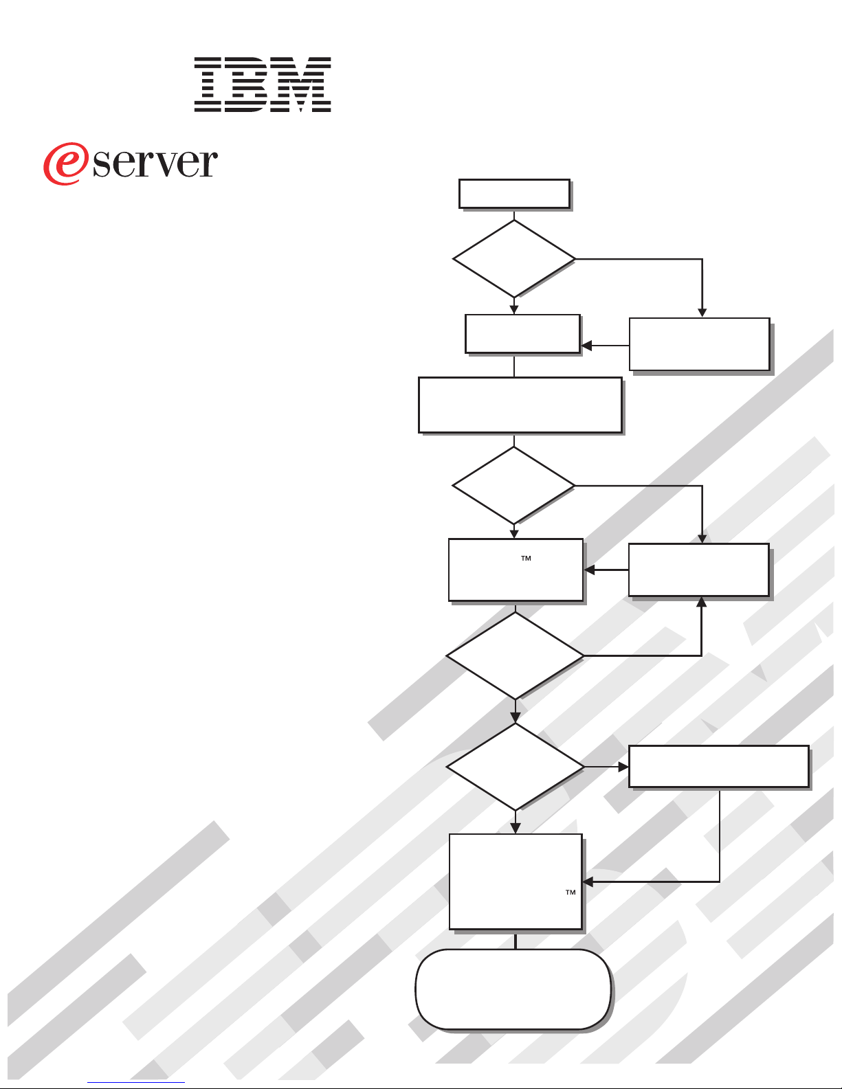
Start the server.
Installation Guide
Welcome.
This server
contains information for setting
up and configuring your server.
For detailed information about
your server, view the publications
on the
Documentation CD.
You can also find the most
current information about your
server at http://www.ibm.com/support/.
Installation Guide
Did the server
start correctly?
Ye s
Turn off the server
and install options.
Install the server in the rack cabinet
and cable the server and options;
then, restart the server.
Did the server
start correctly?
Ye s
Use the IBM
ServerGuide program
to set up and
configure hardware.
Was the
server setup
completed?
No
No
No
Go to the Server Support
flow chart on the reverse
side of this page.
Go to the Server Support
flow chart on the reverse
side of this page.
Ye s
Use
ServerGuide to
install the operating
system?
Ye s
Install applications,
such as IBM systems
management software
and IBM ServeRAID
programs
The server is ready to use.
Go to
http://www.ibm.com/pc/register/
to register the server.
No
Go to the Web for instructions:
http://www.ibm.com/support/
Page 2
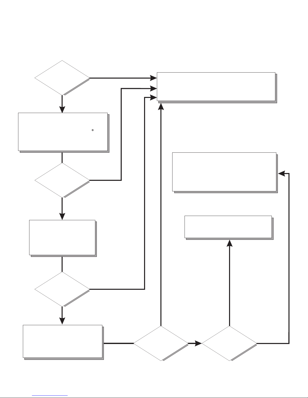
Server Support
Is the server working
correctly?
Ye s
No
Check all cables for loose connections
and verify that all optional devices you
installed are on the ServerProven list at
http://www.ibm.com/servers/eserver/
serverproven/compat/us/.
Is the problem
solved?
Ye s
No
Register the server. Go to
http://www.ibm.com/pc/register/.
View information about IBM Support Line at
http://www.ibm.com/services/sl/products/
or view support telephone numbers at
http://www.ibm.com/planetwide/.
See the troubleshooting
information that comes with
the server to determine
the cause of the problem
and the action to take.
Is the problem
solved?
Ye s
No
Update the firmware to the
latest level.
You can download firmware from
http://www.ibm.com/support/
Ye s
Is the problem
solved?
View support telephone numbers at
http://www.ibm.com/planetwide/.
Hardware
No Software
Hardware or
software problem?
Page 3

eServer 32 6m Typ e 7969
Installation Guid e
Page 4

Note: Before using this information and the product it supports, read the general information in Appendix B, “Notices,” on page 55.,
and the Warranty and Support Information document on the IBM Eserver Documentation CD.
Second Edition (November 2005)
© Copyright International Business Machines Corporation 2005. All rights reserved.
US Government Users Restricted Rights – Use, duplication or disclosure restricted by GSA ADP Schedule Contract
with IBM Corp.
Page 5

Contents
Safety . . . . . . . . . . . . . . . . . . . . . . . . . . . .v
Chapter 1. Introduction . . . . . . . . . . . . . . . . . . . . . .1
The IBM Eserver Documentation CD . . . . . . . . . . . . . . . . .2
Hardware and software requirements . . . . . . . . . . . . . . . .2
Using the Documentation Browser . . . . . . . . . . . . . . . . .2
Notices and statements used in this document . . . . . . . . . . . . . .3
Features and specifications . . . . . . . . . . . . . . . . . . . . .4
Major components of the Eserver 326m Type 7969 server . . . . . . . . .6
Chapter 2. Installing options . . . . . . . . . . . . . . . . . . . .9
Installation guidelines . . . . . . . . . . . . . . . . . . . . . . .9
System reliability guidelines . . . . . . . . . . . . . . . . . . .10
Handling static-sensitive devices . . . . . . . . . . . . . . . . .10
Removing the cover and bezel . . . . . . . . . . . . . . . . . . .10
Installing an adapter . . . . . . . . . . . . . . . . . . . . . . .11
Installing a hard disk drive . . . . . . . . . . . . . . . . . . . . .18
Installing a hot-swap hard disk drive . . . . . . . . . . . . . . . .18
Installing a non-hot-swap hard disk drive . . . . . . . . . . . . . .20
Installing a memory module . . . . . . . . . . . . . . . . . . . .21
Installing an additional microprocessor . . . . . . . . . . . . . . . .23
Completing the installation . . . . . . . . . . . . . . . . . . . . .26
Connecting the cables . . . . . . . . . . . . . . . . . . . . .27
Updating the server configuration . . . . . . . . . . . . . . . . .28
Chapter 3. Server controls, LEDs, and power . . . . . . . . . . . . .29
Front view . . . . . . . . . . . . . . . . . . . . . . . . . .29
Rear view . . . . . . . . . . . . . . . . . . . . . . . . . . .31
Server power features . . . . . . . . . . . . . . . . . . . . . .32
Turning on the server . . . . . . . . . . . . . . . . . . . . .32
Turning off the server . . . . . . . . . . . . . . . . . . . . .32
Chapter 4. Configuring the server . . . . . . . . . . . . . . . . .35
Using the ServerGuide Setup and Installation CD . . . . . . . . . . . .35
Installing your operating system without using ServerGuide . . . . . . . .36
Using the Configuration/Setup Utility program . . . . . . . . . . . . .36
Using the baseboard management controller firmware update program . . . .37
Using the RAID configuration programs . . . . . . . . . . . . . . . .37
Using the LSI Logic Configuration Utility program . . . . . . . . . . .38
Using ServeRAID Manager . . . . . . . . . . . . . . . . . . .38
Configuring the controller . . . . . . . . . . . . . . . . . . .39
Viewing the configuration . . . . . . . . . . . . . . . . . . .40
Using the ServeRAID configuration programs . . . . . . . . . . . . . .40
Chapter 5. Solving problems . . . . . . . . . . . . . . . . . . .41
Diagnostic tools overview . . . . . . . . . . . . . . . . . . . . .41
POST beep code descriptions . . . . . . . . . . . . . . . . . . .41
POST error messages . . . . . . . . . . . . . . . . . . . . . .45
ServerGuide problems . . . . . . . . . . . . . . . . . . . . . .46
Troubleshooting charts . . . . . . . . . . . . . . . . . . . . . .47
CD drive problems . . . . . . . . . . . . . . . . . . . . . .47
Diskette drive problems . . . . . . . . . . . . . . . . . . . . .47
Expansion enclosure problems . . . . . . . . . . . . . . . . . .47
© Copyright IBM Corp. 2005 iii
Page 6

General problems . . . . . . . . . . . . . . . . . . . . . . .47
Hard disk drive problems . . . . . . . . . . . . . . . . . . . .48
Intermittent problems . . . . . . . . . . . . . . . . . . . . . .48
Keyboard, mouse, or pointing-device problems . . . . . . . . . . . .48
Memory problems . . . . . . . . . . . . . . . . . . . . . . .49
Microprocessor problems . . . . . . . . . . . . . . . . . . . .49
Monitor problems . . . . . . . . . . . . . . . . . . . . . . .49
Option problems . . . . . . . . . . . . . . . . . . . . . . .50
Power problems . . . . . . . . . . . . . . . . . . . . . . .51
Serial port problems . . . . . . . . . . . . . . . . . . . . . .51
Software problems . . . . . . . . . . . . . . . . . . . . . .51
Universal Serial Bus device problems . . . . . . . . . . . . . . .52
Appendix A. Getting help and technical assistance . . . . . . . . . .53
Before you call . . . . . . . . . . . . . . . . . . . . . . . . .53
Using the documentation . . . . . . . . . . . . . . . . . . . . .53
Getting help and information from the World Wide Web . . . . . . . . . .54
Software service and support . . . . . . . . . . . . . . . . . . .54
Hardware service and support . . . . . . . . . . . . . . . . . . .54
Appendix B. Notices . . . . . . . . . . . . . . . . . . . . . .55
Edition notice . . . . . . . . . . . . . . . . . . . . . . . . .55
Trademarks . . . . . . . . . . . . . . . . . . . . . . . . . .56
Important notes . . . . . . . . . . . . . . . . . . . . . . . . .56
Product recycling and disposal . . . . . . . . . . . . . . . . . . .57
Battery return program . . . . . . . . . . . . . . . . . . . . . .58
Electronic emission notices . . . . . . . . . . . . . . . . . . . .59
Federal Communications Commission (FCC) statement . . . . . . . . .59
Industry Canada Class A emission compliance statement . . . . . . . .59
Australia and New Zealand Class A statement . . . . . . . . . . . .59
United Kingdom telecommunications safety requirement . . . . . . . . .59
European Union EMC Directive conformance statement . . . . . . . . .59
Taiwanese Class A warning statement . . . . . . . . . . . . . . .60
Chinese Class A warning statement . . . . . . . . . . . . . . . .60
Japanese Voluntary Control Council for Interference (VCCI) statement . . .60
Power cords . . . . . . . . . . . . . . . . . . . . . . . . . .60
Index . . . . . . . . . . . . . . . . . . . . . . . . . . . .63
iv eServer 326m Type 7969: Installation Guide
Page 7
Safety
Before installing this product, read the Safety Information.
Antes de instalar este produto, leia as Informações de Segurança.
Pred instalací tohoto produktu si prectete prírucku bezpecnostních instrukcí.
Læs sikkerhedsforskrifterne, før du installerer dette produkt.
Lees voordat u dit product installeert eerst de veiligheidsvoorschriften.
Ennen kuin asennat tämän tuotteen, lue turvaohjeet kohdasta Safety Information.
Avant d’installer ce produit, lisez les consignes de sécurité.
Vor der Installation dieses Produkts die Sicherheitshinweise lesen.
Prima di installare questo prodotto, leggere le Informazioni sulla Sicurezza.
Les sikkerhetsinformasjonen (Safety Information) før du installerer dette produktet.
Antes de instalar este produto, leia as Informações sobre Segurança.
© Copyright IBM Corp. 2005 v
Page 8

Antes de instalar este producto, lea la información de seguridad.
Läs säkerhetsinformationen innan du installerar den här produkten.
vi eServer 326m Type 7969: Installation Guide
Page 9
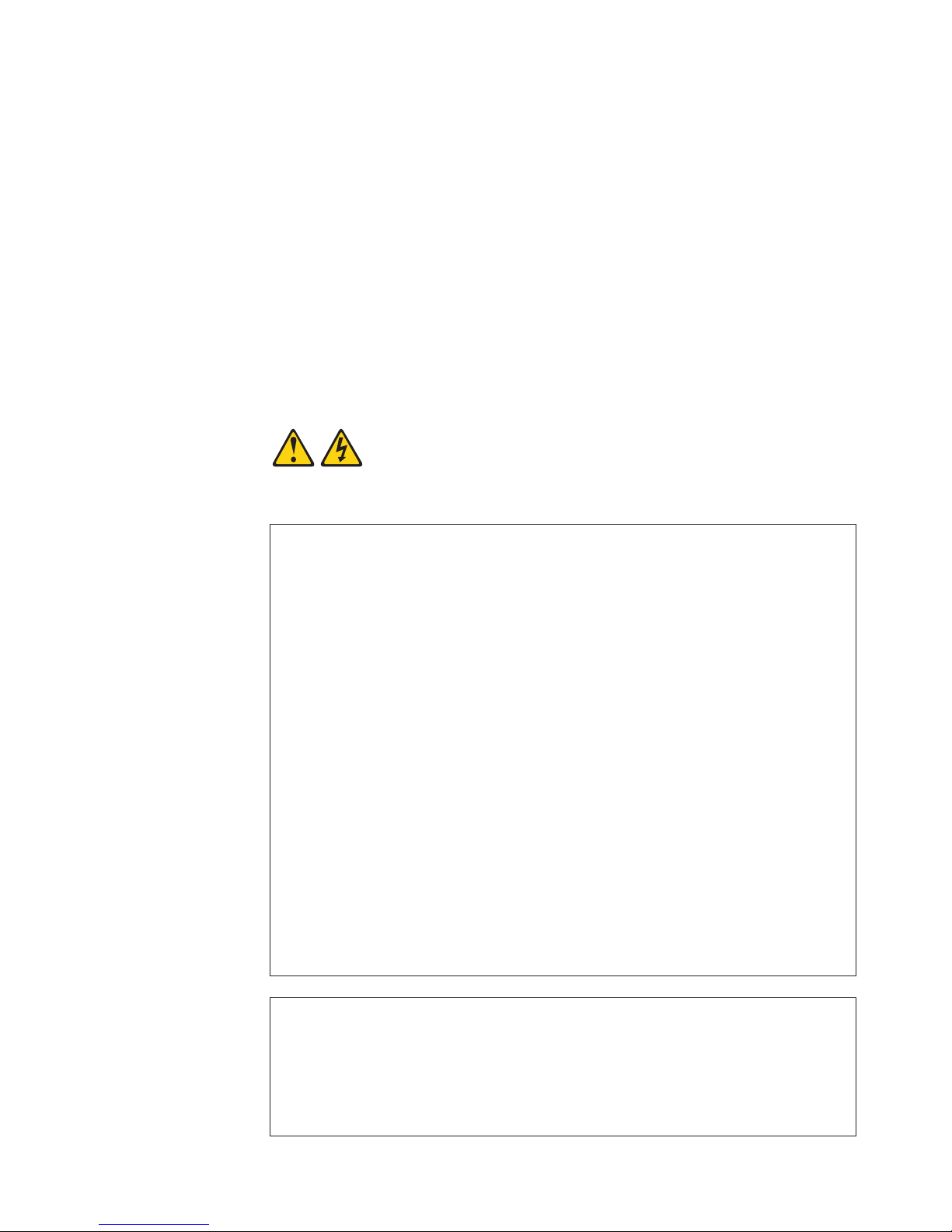
Important:
All caution and danger statements in this documentation begin with a
number. This number is used to cross reference an English caution or
danger statement with translated versions of the caution or danger
statement in the IBM Safety Information book.
For example, if a caution statement begins with a number 1,
translations for that caution statement appear in the IBM Safety
Information book under statement 1.
Be sure to read all caution and danger statements in this
documentation before performing the instructions. Read any additional
safety information that comes with your server or optional device before
you install the device.
Statement 1:
DANGER
Electrical
current from power, telephone, and communication cables is
hazardous.
To avoid a shock hazard:
v Do not connect or disconnect any cables or perform installation,
maintenance, or reconfiguration of this product during an electrical
storm.
v Connect all power cords to a properly wired and grounded electrical
outlet.
v Connect to properly wired outlets any equipment that will be attached to
this product.
v When possible, use one hand only to connect or disconnect signal
cables.
v Never turn on any equipment when there is evidence of fire, water, or
structural damage.
v Disconnect the attached power cords, telecommunications systems,
networks, and modems before you open the device covers, unless
instructed otherwise in the installation and configuration procedures.
v Connect and disconnect cables as described in the following table when
installing, moving, or opening covers on this product or attached
devices.
To Connect: To Disconnect:
1. Turn everything OFF.
2. First, attach all cables to devices.
3. Attach signal cables to connectors.
4. Attach power cords to outlet.
5. Turn device ON.
1. Turn everything OFF.
2. First, remove power cords from outlet.
3. Remove signal cables from connectors.
4. Remove all cables from devices.
Safety vii
Page 10

Statement 2:
CAUTION:
When replacing the lithium battery, use only IBM Part Number 33F8354 or an
equivalent type battery recommended by the manufacturer. If your system has
a module containing a lithium battery, replace it only with the same module
type made by the same manufacturer. The battery contains lithium and can
explode if not properly used, handled, or disposed of.
Do not:
v Throw or immerse into water
v Heat to more than 100°C (212°F)
v Repair or disassemble
Dispose of the battery as required by local ordinances or regulations.
viii eServer 326m Type 7969: Installation Guide
Page 11
Statement 3:
CAUTION:
When laser products (such as CD-ROMs, DVD drives, fiber optic devices, or
transmitters) are installed, note the following:
v Do not remove the covers. Removing the covers of the laser product could
result in exposure to hazardous laser radiation. There are no serviceable
parts inside the device.
v Use of controls or adjustments or performance of procedures other than
those specified herein might result in hazardous radiation exposure.
DANGER
laser products contain an embedded Class 3A or Class 3B laser
Some
diode. Note the following.
Laser radiation when open. Do not stare into the beam, do not view directly
with optical instruments, and avoid direct exposure to the beam.
Class 1 Laser Product
Laser Klasse 1
Laser Klass 1
Luokan 1 Laserlaite
Appareil A Laser de Classe 1
`
Safety ix
Page 12
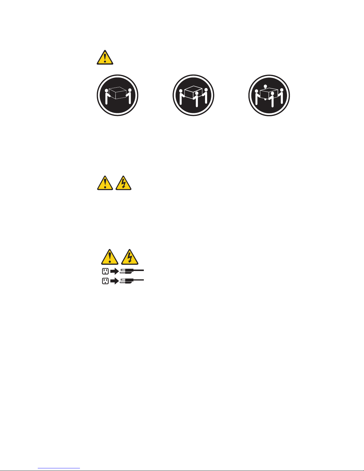
Statement 4:
≥ 18 kg (39.7 lb) ≥ 32 kg (70.5 lb) ≥ 55 kg (121.2 lb)
CAUTION:
Use safe practices when lifting.
Statement 5:
CAUTION:
The power control button on the device and the power switch on the power
supply do not turn off the electrical current supplied to the device. The device
also might have more than one power cord. To remove all electrical current
from the device, ensure that all power cords are disconnected from the power
source.
2
1
x eServer 326m Type 7969: Installation Guide
Page 13
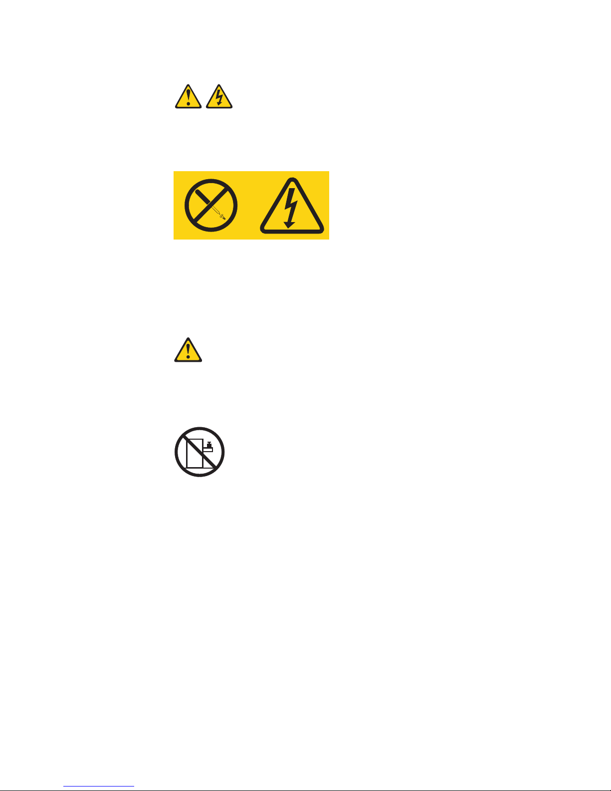
Statement 8:
CAUTION:
Never remove the cover on a power supply or any part that has the following
label attached.
Hazardous voltage, current, and energy levels are present inside any
component that has this label attached. There are no serviceable parts inside
these components. If you suspect a problem with one of these parts, contact
a service technician.
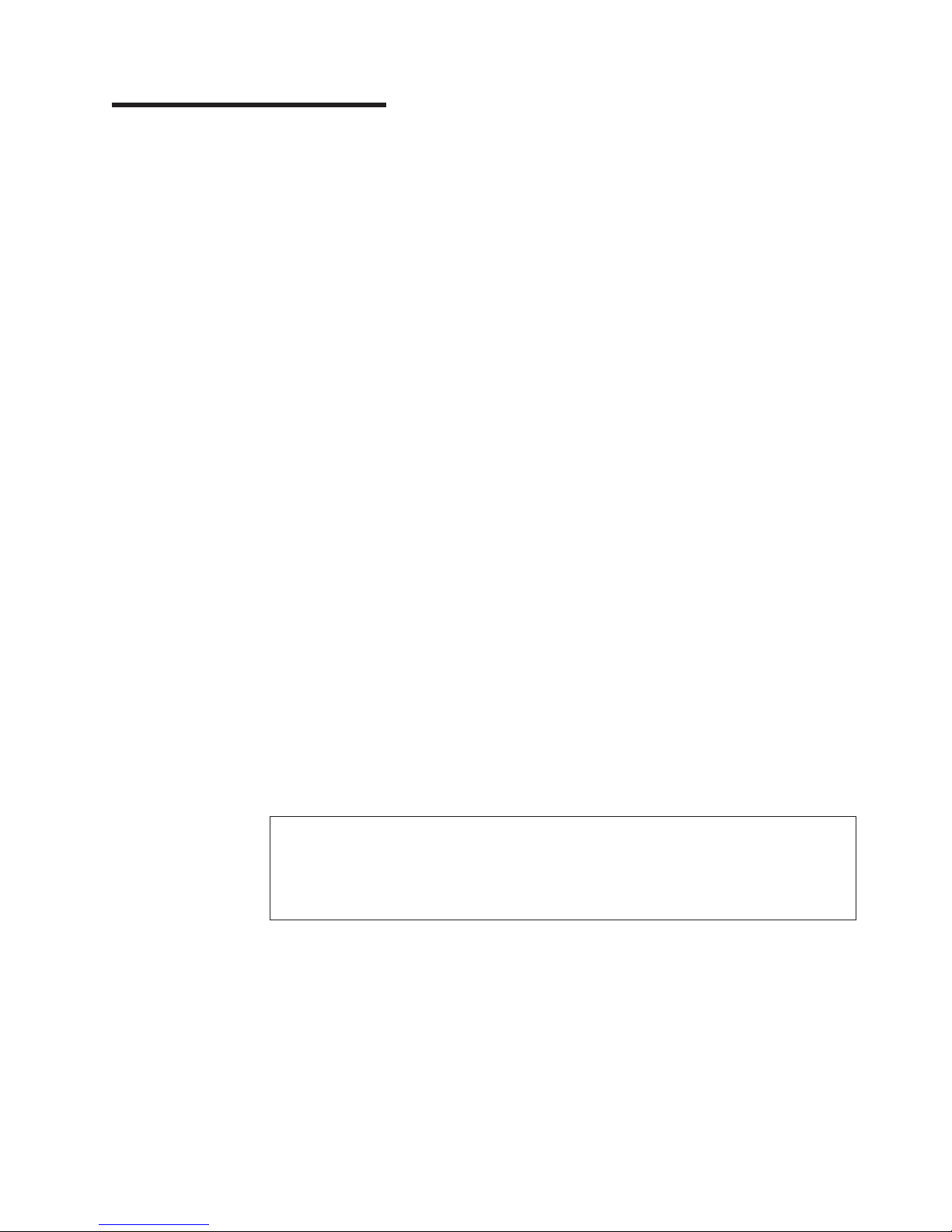
Statement 10:
CAUTION:
Do not place any object weighing more than 82 kg (180 lb) on top of
rack-mounted devices.
>82 kg (180 lb)
WARNING: Handling the cord on this product or cords associated with accessories
sold with this product, will expose you to lead, a chemical known to the State of
California to cause cancer, and birth defects or other reproductive harm. Wash
hands after handling.
ADVERTENCIA: El contacto con el cable de este producto o con cables de
accesorios que se venden junto con este producto, pueden exponerle al plomo, un
elemento químico que en el estado de California de los Estados Unidos está
considerado como un causante de cancer y de defectos congénitos, además de
otros riesgos reproductivos. Lávese las manos después de usar el producto.
Safety xi
Page 14

xii eServer 326m Type 7969: Installation Guide
Page 15
Chapter 1. Introduction
This Installation Guide contains instructions for setting up your IBM
326m Type 7969 server and basic instructions for installing some options. More
detailed instructions for installing options are in the Option Installation Guide on the
IBM Eserver Documentation CD, which comes with the server. This document
contains information about:
v Setting up and cabling the server
v Starting and configuring the server
v Installing some options
v Solving problems
server might have features that are not described in the documentation that
The
you received with the server. The documentation might be updated occasionally to
include information about those features, or technical updates might be available to
provide additional information that is not included in the server documentation.
These updates are available from the IBM Web site. To check for updated
documentation and technical updates, complete the following steps.
Note: Changes are made periodically to the IBM Web site. The actual procedure
might vary slightly from what is described in this document.
1. Go to http://www.ibm.com/support/.
2. Under Search technical support, type 7969, and click Search.
®
Eserver
™
™
server comes with an IBM ServerGuide
The
Setup and Installation CD to help you
configure the hardware, install device drivers, and install the operating system.
The server comes with a limited warranty (see the IBM Warranty and Support
Information document on the IBM Eserver Documentation CD). You can obtain
up-to-date information about the server at
http://www.ibm.com/pc/us/eserver/opteron/. Yo u can obtain information about other
IBM server products at http://www.ibm.com/eserver/xseries/.
Record information about the server in the following table. You will need this
information when you register the server with IBM.
Product name IBM Eserver 326m server
Machine type 7969
Model number _____________________________________________
Serial number _____________________________________________
© Copyright IBM Corp. 2005 1
Page 16
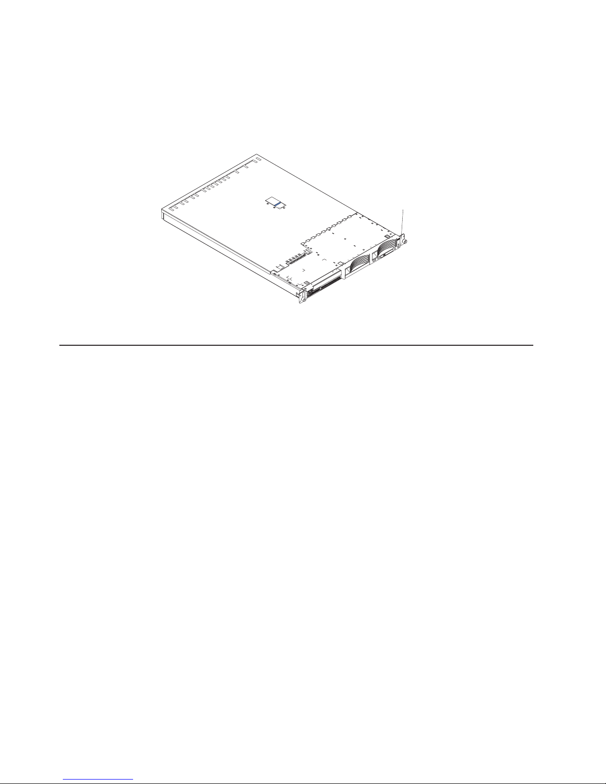
The model number and serial number are on the ID label on the right mounting
bracket on the server, as shown in the following illustration.
Note: This illustration shows a small computer system interface (SCSI) model
server. A Serial ATA (S ATA ) non-hot-swap hard disk drive model is also
available. This illustration might differ slightly from your hardware.
ID label
See the Rack Installation Instructions document for complete rack installation and
removal instructions.
The IBM Eserver Documentation CD
The IBM Eserver Documentation CD contains documentation for your server in
Portable Document Format (PDF) and includes the IBM Documentation Browser to
help you find information quickly.
Hardware and software requirements
The IBM Eserver Documentation CD requires the following minimum hardware
and software:
v Microsoft Windows NT 4.0 (with Service Pack 3 or later), Windows 2000, or Red
Hat Linux.
v 100 MHz microprocessor.
v 32 MB of RAM.
v Adobe Acrobat Reader 3.0 (or later) or xpdf, which comes with Linux operating
systems. Acrobat Reader software is included on the CD, and you can install it
when you run the Documentation Browser.
Using the Documentation Browser
Use the Documentation Browser to browse the contents of the CD, read brief
descriptions of the documents, and view documents using Adobe Acrobat Reader or
xpdf. The Documentation Browser automatically detects the regional settings in use
in your server and displays the documents in the language for that region (if
available). If a document is not available in the language for that region, the
English-language version is displayed.
2 eServer 326m Type 7969: Installation Guide
Page 17

Use one of the following procedures to start the Documentation Browser:
v If Autostart is enabled, insert the CD into the CD-ROM drive. The Documentation
Browser starts automatically.
v If Autostart is disabled or is not enabled for all users, use one of the following
procedures:
– If you are using a Windows operating system, insert the CD into the CD drive
and click Start --> Run. In the Open field, type
e:\win32.bat
where e is the drive letter of the CD drive, and click OK.
– If you are using Red Hat Linux, insert the CD into the CD drive; then, run the
following command from the /mnt/cdrom directory:
sh runlinux.sh
Select your server from the Product menu. The Available Topics list displays all
the documents for your server. Some documents might be in folders. A plus sign (+)
indicates each folder or document that has additional documents under it. Click the
plus sign to display the additional documents.
When you select a document, a description of the document appears under Topic
Description. To select more than one document, press and hold the Ctrl key while
you select the documents. Click View Book to view the selected document or
documents in Acrobat Reader or xpdf. If you selected more than one document, all
the selected documents are opened in Acrobat Reader or xpdf.
To search all the documents, type a word or word string in the Search field and
click Search. The documents in which the word or word string appears are listed in
order of the most occurrences. Click a document to view it, and press Crtl+F to use
the Acrobat search function or Alt+F to use the xpdf search function within the
document.
Click Help for detailed information about using the Documentation Browser.
Notices and statements used in this document
The caution and danger statements that appear in this document are also in the
multilingual Safety Information document, which is on the IBM Eserver
Documentation CD. Each statement is numbered for reference to the corresponding
statement in the Safety Information document.
The following notices and statements are used in this document:
v Notes: These notices provide important tips, guidance, or advice.
v Important: These notices provide information or advice that might help you avoid
inconvenient or problem situations.
v Attention: These notices indicate potential damage to programs, devices, or
data. An attention notice is placed just before the instruction or situation in which
damage could occur.
v Caution: These statements indicate situations that can be potentially hazardous
to you. A caution statement is placed just before the description of a potentially
hazardous procedure step or situation.
Chapter 1. Introduction 3
Page 18

v Danger: These statements indicate situations that can be potentially lethal or
extremely hazardous to you. A danger statement is placed just before the
description of a potentially lethal or extremely hazardous procedure step or
situation.
Features and specifications
The following information is a summary of the features and specifications of the
server. Depending on the server model, some features might not be available, or
some specifications might not apply.
Racks are marked in vertical increments of 1.75 inches. Each increment is referred
to as a unit, or “U.” A 1-U-high device is 1.75 inches tall.
4 eServer 326m Type 7969: Installation Guide
Page 19

Table 1. Features and specifications
Microprocessor:
v AMD Opteron
™
processor
v 1 MB Level-2 cache
Use the Configuration/Setup
Note:
Utility program to determine the type
and speed of the microprocessors.
Memory:
v Minimum: 1024 MB
v Maximum: 16 GB
v Type: PC3200 error correcting
code (ECC), double-data rate
(DDR) SDRAM, registered DIMMs
with Chipkill
™
memory protection
v Sizes: 512 MB, 1 GB, or 2 GB
DIMMS in pairs
v Four interleaved slots with
standard microprocessor
v Four additional interleaved slots
with optional microprocessor
Drives:
v CD: Slim IDE (standard only on
some models)
v Hard disk drives:
– Slim-high 3.5-inch drives,
hot-swap SCSI or
non-hot-swap Serial ATA
(S ATA) (drive capacity and
speed vary with model)
– Maximum: Two
Expansion
slots:
v Two, used in either of the
following configurations:
– One 133 MHz/64-bit PCI-X
(full-length) and one PCI
Express x8 (half-length)
– One PCI Express x8
(half-length) and one PCI
Express x8 (full length) with
purchase of PCI Express x8
riser card
Supports 3.3 V or universal
v
adapters only
Video controller:
v ATI RN50b video controller on
system board
v Compatible with SVGA
v 16 MB DDR1 video memory
Power
supply:
One 411 watt (115-230 V ac)
Size:
v Height: 43 mm (1.69 in.)
v Depth: 660 mm (25.98 in.)
v Width: 440 mm (17.32 in.)
v Weight: approximately 12.7 kg (28
lb) when fully configured
Integrated
functions:
v Baseboard management controller
v One single-channel LSI Ultra320
SCSI controller
v Two Broadcom 10/100/1000
Ethernet controllers (dual-port
design) with Wake on LAN
®
support
v Four Universal Serial Bus (USB)
ports
v One serial port
v One video port
The baseboard management
Note:
controller is also known as the
service processor.
Acoustical noise emissions:
v Declared sound power, idling: 6.5
bels
v Declared sound power, operating:
6.5 bels
Environment:
v Air temperature:
– Server on: 10°to 35°C (50.0° to
95.0°F). Altitude: 0 to 914 m
(2998.7 ft)
– Server on: 10° to 32°C (50.0° to
89.6°F). Altitude: 914 m (2998.7
ft) to 2133 m (6998.0 ft)
– Server off: 10° to 43°C (50.0° to
109.4°F). Maximum altitude:
2133 m (6998.0 ft)
Humidity:
v
– Server on: 8% to 80%
– Server off: 8% to 80%
Airflow rates:
v
– Minimum: 28 CFM
– Maximum: 47 CFM
Heat output:
Approximate heat output in British
thermal units (Btu) per hour for dual
multiprocessor configurations:
v Minimum configuration: 409 Btu (120
watts)
v Maximum configuration: 1366 Btu
(400 watts)
Electrical
input:
v Sine-wave input (50-60 Hz) required
v Input voltage low range:
– Minimum: 100 V ac
– Maximum: 127 V ac
Input voltage high range:
v
– Minimum: 200 V ac
– Maximum: 240 V ac
Input kilovolt-amperes (kVA),
v
approximately:
– Minimum: 0.120 kVA
– Maximum: 0.400 kVA
Notes:
1. Power consumption and heat output
vary depending on the number and
type of optional features installed
and the power-management optional
features in use.
2. These levels were measured in
controlled acoustical environments
according to the procedures
specified by the American National
Standards Institute (ANSI) S12.10
and ISO 7779 and are reported in
accordance with ISO 9296. Actual
sound-pressure levels in a given
location might exceed the average
values stated because of room
reflections and other nearby noise
sources. The declared sound-power
levels indicate an upper limit, below
which a large number of computers
will operate.
Chapter 1. Introduction 5
Page 20

Major components of the Eserver 326m Type 7969 server
Blue on a component indicates touch points, where you can grip the component to
remove it in the server, open or close a latch, and so on.
Orange on a component or an orange label on or near a component indicates that
the component can be hot-swapped, which means that if the server and operating
system support hot-swap capability, you can remove or install the component while
the server is running. (Orange can also indicate touch points on hot-swap
components.) See the instructions for removing or installing a specific hot-swap
component for any additional procedures that you might have to perform before you
remove or install the component.
6 eServer 326m Type 7969: Installation Guide
Page 21
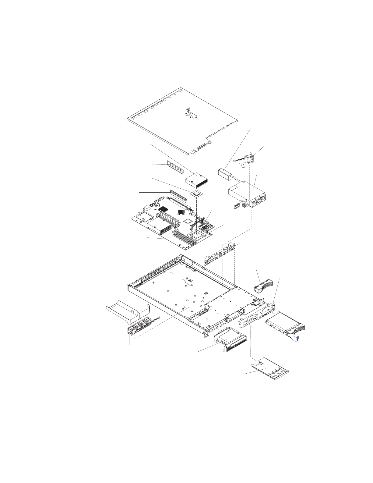
The following illustration shows the locations of major components in a SCSI
hot-swap hard disk drive model server. A SATA non-hot-swap hard disk drive model
is also available.
Note: The illustrations in this document might differ slightly from your hardware.
Power-cord module
Hard disk drive
Microprocessor
heat sink
Dual inline
memory module
(DIMM)
Microprocessor
Riser card
Microprocessor
socket
fan/air baffle
Power supply
System board
Air baffle
Microprocessor fans
Heat-sink
retention
module
Hot-swap hard disk
drive SCSI backplane
(SCSI model only)
Filler panel (SCSI model only)
Bezel
(SCSI model only)
Hard disk drive
CD-ROM
drive assembly
USB option tray
Chapter 1. Introduction 7
Page 22

8 eServer 326m Type 7969: Installation Guide
Page 23

Chapter 2. Installing options
This chapter provides basic instructions for installing hardware options in the server.
These instructions are intended for users who are experienced with setting up IBM
server hardware. If you need more detailed instructions, see the Option Installation
Guide on the IBM Eserver Documentation CD.
Installation guidelines
Before you install, read the following information:
v Read the safety information that begins on page v, and the guidelines in
“Handling static-sensitive devices” on page 10. This information will help you
work safely.
v Before you install optional hardware, make sure that the server is working
correctly. Start the server, and make sure that the operating system starts, if an
operating system is installed, or that a 19990305 error code is displayed,
indicating that an operating system was not found but the server is otherwise
working correctly. If the server is not working correctly, see the Hardware
Maintenance Manual and Troubleshooting Guide for diagnostic information.
v Observe good housekeeping in the area where you are working. Place removed
covers and other parts in a safe place.
v If you must start the server while the cover is removed, make sure that no one is
near the server and that no tools or other objects have been left inside the
server.
v Do not attempt to lift an object that you think is too heavy for you. If you have to
lift a heavy object, observe the following precautions:
– Make sure that you can stand safely without slipping.
– Distribute the weight of the object equally between your feet.
– Use a slow lifting force. Never move suddenly or twist when you lift a heavy
object.
– To avoid straining the muscles in your back, lift by standing or by pushing up
with your leg muscles.
Make sure that you have an adequate number of properly grounded electrical
v
outlets for the server, monitor, and other devices.
v Back up all important data before you make changes to disk drives.
v Have a small flat-blade screwdriver available.
v You do not have to turn off the server to install or replace hot-swap power
supplies, hot-swap fans, or hot-plug Universal Serial Bus (USB) devices.
However, you must turn off the server before performing any steps that involve
removing or installing adapter cables.
v Blue on a component indicates touch points, where you can grip the component
to remove it from or install it in the server, open or close a latch, and so on.
v Orange on a component or an orange label on or near a component indicates
that the component can be hot-swapped, which means that if the server and
operating system support hot-swap capability, you can remove or install the
component while the server is running. (Orange can also indicate touch points on
hot-swap components.) See the instructions for removing or installing a specific
hot-swap component for any additional procedures that you might have to
perform before you remove or install the component.
v When you are finished working on the server, reinstall all safety shields, guards,
labels, and ground wires.
© Copyright IBM Corp. 2005 9
Page 24

v For a list of supported options for the server, go to
http://www.ibm.com/servers/eserver/serverproven/compat/us/
System reliability guidelines
To help ensure proper system cooling and system reliability, make sure that:
v Each of the drive bays has a drive or a filler panel and electromagnetic
compatibility (EMC) shield installed in it.
v There is adequate space around the server to allow the server cooling system to
work properly. Leave approximately 50 mm (2.0 in.) of open space around the
front and rear of the server. Do not place objects in front of the fans. For proper
cooling and airflow, replace the server cover before turning on the server.
Operating the server for extended periods of time (more than 30 minutes) with
the server cover removed might damage server components.
v You have followed the cabling instructions that come with optional adapters.
v You have replaced a failed fan as soon as possible.
v You have replaced a hot-swap drive within 2 minutes of removal.
Handling static-sensitive devices
Attention: Static electricity can damage the server and other electronic devices.
To avoid damage, keep static-sensitive devices in their static-protective packages
until you are ready to install them.
To reduce the possibility of damage from electrostatic discharge, observe the
following precautions:
v Limit your movement. Movement can cause static electricity to build up around
you.
v The use of a grounding system is recommended. For example, wear an
electrostatic-discharge wrist strap, if one is available.
v Handle the device carefully, holding it by its edges or its frame.
v Do not touch solder joints, pins, or exposed circuitry.
v Do not leave the device where others can handle and damage it.
v While the device is still in its static-protective package, touch it to an unpainted
metal surface on the outside of the server for at least 2 seconds. This drains
static electricity from the package and from your body.
v Remove the device from its package and install it directly into the server without
setting down the device. If it is necessary to set down the device, put it back into
its static-protective package. Do not place the device on the server cover or on a
metal surface.
v Take additional care when handling devices during cold weather. Heating reduces
indoor humidity and increases static electricity.
Removing the cover and bezel
Important: Before you install optional hardware, make sure that the server is
working correctly. Start the server, and make sure that the operating
system starts, if an operating system is installed, or that a 19990305
error code is displayed, indicating that an operating system was not
found but the server is otherwise working correctly. If the server is not
working correctly, see the Hardware Maintenance Manual and
Troubleshooting Guide for diagnostic information.
10 eServer 326m Type 7969: Installation Guide
Page 25
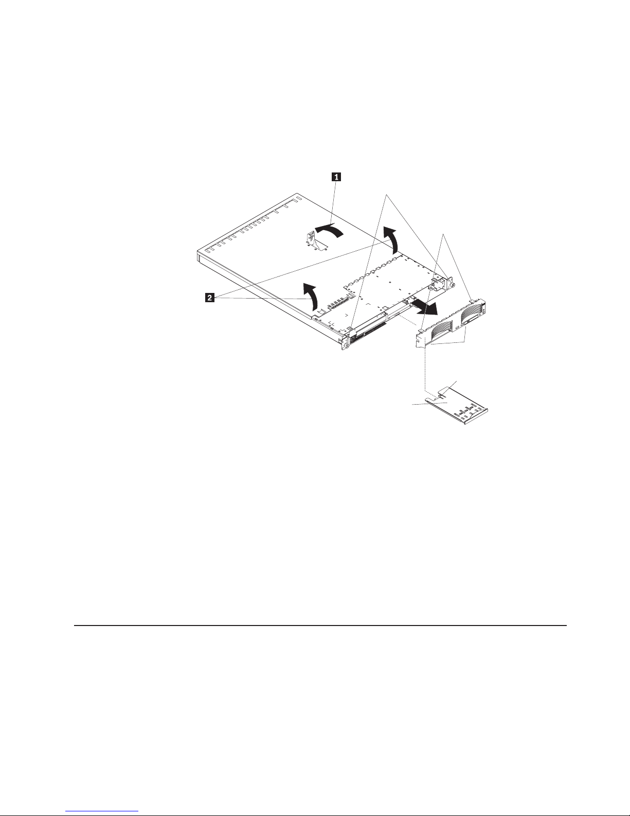
To remove the cover and bezel (with the server out of the rack), complete the
following steps:
1. Read the safety information that begins on page v, and “Installation guidelines”
on page 9.
2. Turn off the server and all attached peripheral devices. Disconnect all power
cords; then, disconnect all external signal cables from the server.
3. Lift the cover release latch; the cover slides toward the rear.
Captive screws
Bezel retention
tabs
4. Slide the cover back, and lift the cover off the server.
5. Press in on the USB option tray (below hard disk drive bay 1) to release it and
slide the tray out until it stops; then, press the retention clip at the bottom rear
of the tray and remove the tray from the server.
Note: You need to remove the USB option tray and the bezel only if you are
6. Press on the bezel retention tabs on the top, right side and bottom of the server,
and pull the bezel directly away from the server.
Attention: For proper cooling and airflow, replace the cover before turning on the
server. Operating the server for extended periods of time (more than 30 minutes)
with the cover removed might damage server components.
Installing an adapter
Bezel
retention
tabs
Retention
clip
USB option tray
installing a non-hot-swap hard disk drive. It is not necessary if you are
installing other options in the server.
The following notes describe the types of adapters that the server supports and
other information that you must consider when installing an adapter:
v Locate the documentation that comes with the adapter and follow those
instructions in addition to the instructions in this section. If you must change the
switch settings or jumper settings on the adapter, follow the instructions that
come with the adapter.
Chapter 2. Installing options 11
Page 26

v The server comes with one 64-bit, 133 MHz peripheral component
interconnect-extended (PCI-X) slot (full-length riser card) and one half-length PCI
Express x8 slot. An optional PCI Express x8 slot can be added with a riser card if
the PCI-X riser card is removed first.
v You can install a full-length adapter in slot 1.You can install a half-length adapter
in slot 2.
v The server is designed specifically for PCI-X adapter support, but it also supports
PCI adapters.
v The server supports 3.3 V and universal PCI and PCI-X adapters; it does not
support 5.0-V-only adapters.
v The integrated video controller is on PCI bus 1. The PCI-X expansion slot is on
PCI-X bus 1. The integrated Ethernet controllers are on PCI-X bus 2. The
integrated SCSI controller is on PCI-X bus 3. The PCI Express expansion slots
are on PCI Express buses 1 and 2.
v The server scans PCI-X and PCI Express slots to assign system resources. By
default, the server starts (boots) devices in the following order: system SCSI
devices; PCI express and PCI-X devices; then, IDE and SATA devices.
Note: To change the boot precedence for PCI and PCI-X devices, you must
disable the devices through the Configuration/Setup Utility program. Start
the Configuration/Setup Utility program and select Startup from the main
menu. Then, select Startup Sequence and use the arrow keys to specify
the startup order. For more information, see “Using the
Configuration/Setup Utility program” on page 36 and the User’s Guide on
the IBM Eserver Documentation CD.
v You can install either an optional SCSI adapter or an optional redundant array of
independent disks (RAID) adapter only in PCI-X slot 1. The server supports a
variety of RAID adapters for both internal and external configurations. For the
most current list of supported RAID adapters, see
http://www.ibm.com/servers/eserver/serverproven/compat/us/. For details about
installing a RAID adapter, see the documentation that comes with the adapter.
12 eServer 326m Type 7969: Installation Guide
Page 27

v If you plan to use a RAID adapter to control internal hot-swap hard disk drives,
disconnect the SCSI cable from the SCSI backplane signal connector (SCSI1) on
the system board and connect it to the RAID adapter. The following illustration
shows the cable routing if you are installing the RAID adapter in PCI-X slot 1.
See the documentation that comes with the RAID adapter for any additional
cabling instructions. That documentation also provides information about
installing the RAID software and configuring the RAID adapter.
Chapter 2. Installing options 13
Page 28

v The optional IBM Remote Supervisor Adapter II can be installed only in PCI-X
slot 1. Use the 20-pin planar cable with USB signals that comes with the Remote
Supervisor Adapter II to connect the 20-pin connector on the rear edge of the
adapter to the Remote Supervisor Adapter II connector (JMGT1) on the system
board. For details about installing a Remote Supervisor Adapter II, see the
documentation that comes with the adapter. The following illustration shows the
cable routing.
Remote Supervisor
Adapter II
Remote Supervisor
Adapter II connector
(JMGT1)
20-pin planar cable
with USB signals
14 eServer 326m Type 7969: Installation Guide
Page 29

To install an adapter, complete the following steps:
1. Read the safety information that begins on page v, and “Installation guidelines”
on page 9.
2. Turn off the server and peripheral devices, and disconnect the power cords
and all external cables.
3. Remove the server cover (see “Removing the cover and bezel” on page 10).
4. Determine which PCI slot you will use for the adapter.
PCI-X / PCI Express slot 1
(PCIE1)
PCI Express slot 2
(PCIE2)
Chapter 2. Installing options 15
Page 30

5. On the rear panel, squeeze the expansion-slot clip to unlock the clip; then, pull
the clip out from the server until it stops and rotate the clip as shown in the
following illustration. It remains loosely attached to the server.
Adapter
retention
bracket
Expansion-
Alignment tab
slot clip (adapter slot 1)
Expansionslot clip (adapter slot 2)
Power-cord
module
Retention clip
Attention: Avoid touching the components and gold-edge connectors on the
adapter. Make sure that the adapter is completely and correctly seated in the
slot. Incomplete insertion might cause damage to the system board or to the
adapter.
6. Remove the expansion slot cover from the slot.
7. To gain access to PCI-X slot 1, remove the PCI riser card from its connector.
Riser card
System board
16 eServer 326m Type 7969: Installation Guide
Page 31

8. To gain access to PCI Express slot 2, remove the power-cord module:
a. Press down on the retention clip at the front of the power-cord module and
slide the module toward the front of the server until the alignment tab is
free of the slot on the side of the server.
b. Lift and place the power-cord module out of the server as far as the power
supply cable permits.
9. Install the adapter.
Attention: When you handle static-sensitive devices, take precautions to
avoid damage from static electricity. For information about handling these
devices, see “Handling static-sensitive devices” on page 10.
a. Remove the adapter from the static-protective package and set any
jumpers or switches on the adapter as directed by the adapter
manufacturer. If you are installing a full-length adapter, you might have to
remove a plastic bracket secured to the adapter with two screws before
installing the adapter.
Attention: When you install an adapter, make sure that the adapter is
correctly seated in the connector before you turn on the server. Improperly
seated adapters might cause damage to the system board, the riser card,
or the adapter.
b. If you are installing an adapter in PCI-X slot 1, attach the PCI riser card to
the adapter. Reinstall the PCI riser card with the adapter already attached
to the PCI riser card.
c. Grasp the adapter by its top edge or upper corners, align it with the
connector, and press it firmly into the connector.
Slide the expansion-slot clip toward the server until it snaps into place to
10.
secure the adapter in the adapter slot.
11. Connect any internal cables to the adapter. See the instructions that come with
the adapter for details.
Attention: Make sure that the cables do not block the flow of air from the
fans.
12. If you removed the power-cord module to install the adapter in PCI Express
slot 2, install the module by reversing the procedure in step 8a. Make sure that
the alignment tab is fully seated in the slot on the side of the server.
13. If you installed a full-length adapter in PCI-X slot 1, secure the adapter by
flexing the adapter-retention bracket toward the front of the server and
inserting the front corners of the adapter into the recesses in the latch.
14. Perform any configuration tasks required for the adapter.
If you installed a Remote Supervisor Adapter II, see the documentation that
comes with the Remote Supervisor Adapter II for information about installing
the Remote Supervisor Adapter II firmware and configuring the adapter. After
you initially configure the adapter, create a backup copy of the configuration so
that if you need to replace the adapter in the future, you can restore the
configuration and resume normal operation more quickly.
15. If you have other options to install, install them now. Otherwise, go to
“Completing the installation” on page 26.
Chapter 2. Installing options 17
Page 32

Installing a hard disk drive
The following notes describe the types of hard disk drives that the server supports
and other information that you must consider when installing a hard disk drive:
v The server supports two 25.4-mm (1-inch), slim, 3.5-inch hard disk drives. SCSI
server models come with a hot-swap SCSI backplane.
v The SCSI server models support low voltage differential (LVD) hot-swap drives.
Each hot-swap drive is in a tray, which has a green activity LED and an amber
status LED in the upper-right corner. These LEDs are lit if the drive is active and,
in some cases, if the drive fails. Each hot-swap drive has a single-connectorattached
backplane. The backplane is attached to connector J12 on the system board and
controls the SCSI IDs for the hot-swap drives.
Note: The drive in bay 1 is assigned SCSI ID 0; the drive in bay 2 is assigned
v A non-hot-swap hard disk drive does not require a backplane or tray and it does
not have indicator LEDs. However, you must attach the blue rails that come with
the drive before installing it in the server.
v A non-hot-swap hard disk drive has a jumper block on the rear. Install a jumper
in the cable-selection position of the jumper block. For details, see the notes
under step 4 on page 20, and the documentation that comes with the drive.
v If you install only one hard disk drive, for faster startup, install it in the primary
startup device bay. For hot-swap SCSI drives, the drive in bay 1 is the primary
startup device. For SATA drives, the drive in bay 2 is the primary startup device.
v If you are installing a hot-swap drive, continue with “Installing a hot-swap hard
disk drive.” If you are installing a non-hot-swap drive, go to “Installing a
non-hot-swap hard disk drive” on page 20.
(SCA) connector, which is connected directly into the hot-swap SCSI
SCSI ID 1.
Installing a hot-swap hard disk drive
Before you install a hot-swap hard disk drive, read the following information:
v Inspect the drive tray for signs of damage.
v Make sure that the drive is correctly installed in the tray.
v If the server has an optional RAID adapter, see the documentation that comes
with the adapter for instructions for installing a hard disk drive.
18 eServer 326m Type 7969: Installation Guide
Page 33

To install a hot-swap SCSI hard disk drive, complete the following steps.
Drive bay 2
Filler panel
Hard disk drive
Drive tray
Drive bay 1
Drive tray handle
(in open position)
1. Read the safety information that begins on page v, and “Installation guidelines”
on page 9.
2. Remove the filler panel from the applicable drive bay.
Note: To ensure adequate system cooling, do not operate the server for more
than 2 minutes without either a hard disk drive or a filler panel installed in
each bay.
3. Install the new hard disk drive in the drive bay.
4. Check the hard disk drive status LED and activity LED to verify that the drive is
operating correctly.
5. If you have other options to install, install them now. Otherwise, go to
“Completing the installation” on page 26.
Chapter 2. Installing options 19
Page 34

Installing a non-hot-swap hard disk drive
Before you install a non-hot-swap hard disk drive, read the following information:
v See the documentation that comes with the drive for cabling instructions.
v Route the cable before you install the drive. Do not block the airflow from the
fans.
Complete the following steps to install a non-hot-swap hard disk drive:
Drive bay 1
Drive bay 2
1. Read the safety information that begins on page v, and “Installation guidelines”
on page 9.
2. Turn off the server and peripheral devices, and disconnect the power cords and
all external cables.
3. Remove the server cover (see “Removing the cover and bezel” on page 10).
4. Press in on the USB option tray to release it and slide the tray out until it stops;
then, press the retention clip at the bottom rear of the tray and remove the tray
from the server. Press on the bezel retention tabs and pull the bezel directly
away from the server.
Notes:
a. If you have only one non-hot-swap hard disk drive, install it in the right-hand
bay (bay 2) with a jumper installed in the cable-selection-enabled position of
the jumper block on the rear of the drive.
b. If you have two drives and you want the server to determine the master
drive and subordinate drive automatically, install jumpers in the
cable-selection-enabled position of the jumper block on both drives.
c. If you want to assign master and subordinate drives manually, install a
jumper in the master position for the drive in bay 2 and install a jumper in
the subordinate position for the drive in bay 1.
Install the hard disk drive in the drive bay:
5.
a. Attach the rails to the sides of the drive using two screws for each rail.
b. Slide the drive into the bay until the rail latches snap into place.
c. Connect the signal and power cables to the rear of the drive. Keep the
cables clear of the airflow path of the fan behind the drive bays.
If you have other options to install, install them now. Otherwise, go to
6.
“Completing the installation” on page 26.
20 eServer 326m Type 7969: Installation Guide
Page 35

Installing a memory module
The following notes describe the types of dual inline memory modules (DIMMs) that
the server supports and other information that you must consider when installing
DIMMs:
v The server uses interleaved DIMMs, which you must add, remove, or replace in
pairs. Each pair must be of the same type, capacity, and speed. The server
comes with one pair of DIMMs installed in DIMM slots 1 and 2 on the system
board.
v You can increase the amount of memory in the server by replacing the installed
DIMMs with higher-capacity DIMMs or by installing additional pairs of DIMMs.
v To optimize system performance in a single-microprocessor configuration, install
DIMMs in the following sequence:
DIMM pair DIMM slots
1 1 and 2
2 3 and 4
v To optimize system performance in a dual-microprocessor configuration, install
DIMMs in the following sequence:
DIMM pair DIMM slots
1 1 and 2
2 7 and 8
3 3 and 4
4 5 and 6
v The server supports 512 MB, 1 GB, and 2 GB DIMMs. The memory can be
expanded to a maximum of 16 GB using PC3200 2 GB DIMMs. See the
ServerProven
®
list at
http://www.ibm.com/servers/eserver/serverproven/compat/us/ for a list of memory
modules that the server supports.
Important: The amount of memory installed must be the same for each
microprocessor. For example, if you want to install four 1 GB DIMMs and four
512 MB DIMMs, install one pair of 1 GB DIMMs and one pair of 512 MB DIMMs
for each microprocessor so that the total amount of memory for each
microprocessor equals 3 GB of RAM.
Chapter 2. Installing options 21
Page 36

The following illustration shows the memory slots on the system board.
DIMM 4 (DDR4)
DIMM 3 (DDR3)
DIMM 2 (DDR2)
DIMM 1 (DDR1)
DIMM 8 (DDR8)
DIMM 7 (DDR7)
DIMM 6 (DDR6)
DIMM 5 (DDR5)
To install a DIMM, complete the following steps:
1. Read the safety information that begins on page v, and “Installation guidelines”
on page 9.
2. Turn off the server and peripheral devices, and disconnect the power cords and
all external cables.
3. Remove the server cover (see “Removing the cover and bezel” on page 10).
Attention: To avoid breaking the retaining clips or damaging the DIMM
connectors, open and close the clips gently.
4. Open the retaining clip on each end of the DIMM connector.
5. Touch the static-protective package containing the DIMM to any unpainted metal
surface on the server. Then, remove the DIMM from the package.
6. Turn the DIMM so that the DIMM keys align correctly with the slot.
7. Insert the DIMM into the connector by aligning the edges of the DIMM with the
slots at the ends of the DIMM connector. Firmly press the DIMM straight down
into the connector by applying pressure on both ends of the DIMM
22 eServer 326m Type 7969: Installation Guide
Page 37

simultaneously. The retaining clips snap into the locked position when the DIMM
is firmly seated in the connector. If there is a gap between the DIMM and the
retaining clips, the DIMM has not been correctly inserted; open the retaining
clips, remove the DIMM, and then reinsert it.
Important: In some memory configurations, the 3-3-3 beep code might sound
during POST, followed by a blank monitor screen. If this occurs and the Boot
Diagnostic Screen or QuickBoot Mode feature on the Startup Options menu
of the Configuration/Setup Utility program is enabled (its default setting), you
must restart the server three times to force the basic input/output system (BIOS)
to reset the configuration to the default configuration (the memory connectors
enabled).
8. If you have other options to install, install them now. Otherwise, go to
“Completing the installation” on page 26.
Installing an additional microprocessor
The following notes describe the type of microprocessor that the server supports
and other information that you must consider when installing a microprocessor:
v For a list of microprocessors that the server supports, see
http://www.ibm.com/servers/eserver/serverproven/compat/us/.
v The server comes with one microprocessor installed. The following illustration
shows the two microprocessor sockets on the system board. The voltage
regulator modules (VRMs) for microprocessors 1 and 2 are on the system board.
Microprocessor 1 error
LED (DLED13)
Microprocessor 1 (CPU1)
Microprocessor 2 (CPU2)
Microprocessor 2 error
LED (DLED14)
v If one microprocessor is installed, it is installed in microprocessor socket 1
(CPU1) and supports both the startup and application processes.
v If you install a second microprocessor in the server, the server operates as a
symmetric multiprocessing (SMP) server, and operating-system application
Chapter 2. Installing options 23
Page 38

programs can distribute the processing load between the microprocessors. This
enhances performance for database and point-of-sale applications, integrated
manufacturing solutions, and other applications. Microprocessor 2 is installed in
socket 2 (CPU2).
v If one microprocessor and four DIMMs are installed in the server and you add a
second microprocessor without adding more DIMMs, move the pair of DIMMs in
memory slots 3 and 4 to memory slots 7 and 8.
v Read the documentation that comes with the microprocessor to determine
whether you need to update the BIOS code in the server. To download the most
current level of BIOS code for your server go to http://www.ibm.com/support/ and
click Downloads and drivers.
v (Optional) Obtain an SMP-capable operating system. For a list of supported
operating systems, see
http://www.ibm.com/servers/eserver/serverproven/compat/us/.
v Make sure that the microprocessors are the same type, have the same cache
size, and have the same clock speed.
To install a microprocessor, complete the following steps:
1. Read the safety information that begins on page v, and “Installation guidelines”
on page 9.
2. Turn off the server and peripheral devices, and disconnect the power cords and
all external cables.
3. Remove the server cover (see “Removing the cover and bezel” on page 10);
then, determine the socket where the microprocessor is to be installed.
Attention:
v Avoid touching the components and gold-edge connectors on the
microprocessor. Make sure that the microprocessor is completely and
correctly seated in the socket. Incomplete insertion might cause damage to
the system board or to the microprocessor.
v When you handle static-sensitive devices, take precautions to avoid damage
from static electricity. For information about handling these devices, see
“Handling static-sensitive devices” on page 10.
If you are installing a microprocessor in the microprocessor 2 socket, lift the
4.
microprocessor-locking lever to the open position.
Microprocessorlocking lever
Microprocessor
socket
24 eServer 326m Type 7969: Installation Guide
Page 39

5. Install the microprocessor:
a. Touch the static-protective package containing the new microprocessor to
any unpainted metal surface on the outside of the server; then, remove the
microprocessor from the package.
b. Position the microprocessor over the microprocessor socket as shown in the
following illustration. Carefully press the microprocessor into the socket.
Attention: To avoid bending the pins on the microprocessor, do not use
excessive force when pressing it into the socket.
Microprocessor
Microprocessorlocking lever
Microprocessor
orientation indicator
Microprocessor
socket
6. Close the microprocessor-locking lever to secure the microprocessor.
Note: A new microprocessor comes in a kit with a heat sink.
7. Install the heat sink.
Attention: Do not disturb or contaminate the thermal material on the bottom
of the new heat sink. Doing so damages its heat-conducting capability and
exposes the new microprocessor to overheating.
a. Remove the heat sink from its package and remove the cover from the
bottom of the heat sink.
b. Make sure that the thermal material is still on the bottom of the heat sink,
and position the heat sink on top of the microprocessor.
c. Align the captive screws on the heat sink with the holes on the heat-sink
retention module.
d. Press firmly on the captive screws and tighten them, alternating between
screws until they are tight. Do not overtighten the screws by using excessive
force.
Attention: If you need to remove the heat sink after installing it, note that the
thermal material might have formed a strong bond between the heat sink and
the microprocessor. Do not force the heat sink and microprocessor apart; doing
so can damage the microprocessor pins. Loosening one captive screw fully
before loosening the other captive screw helps break the bond between the
components without damaging them.
Chapter 2. Installing options 25
Page 40

Captive screws
Microprocessor 2
Heat sink
Heat-sink
retention module
Microprocessor socket
8. If you have other options to install, install them now. Otherwise, continue with
“Completing the installation.”
Completing the installation
To complete the installation, complete the following steps:
1. Position the internal cables so they do not interfere with the cover installation.
Attention: Before sliding the cover forward, make sure that all the tabs on
both the front and rear of the cover engage the chassis correctly. If all the tabs
do not engage the chassis correctly, it will be very difficult to remove the cover
later.
2. Position the cover on top of the server and slide it forward. Press down on the
cover latch. The cover slides forward into position. Make sure that the cover
engages the tabs at the front and rear of the server.
3. If you removed the bezel, position the bezel directly in front of the server and
press it into place so that the retention tabs snap into the holes on the top, right
side, and bottom of the server.
4. If you removed the USB option tray, insert it fully into the slot below hard disk
drive bay 1.
26 eServer 326m Type 7969: Installation Guide
Page 41

5. Install the server in the rack. For details, see the Rack Installation Instructions
that come with the server.
6. To attach peripheral devices and connect the power cord, continue with
“Connecting the cables.”
Note: If you installed a SCSI drive, check the LEDs to verify proper operation
Connecting the cables
The following illustrations show the input and output connectors on the front and
rear of the server.
Front
Rear
after you reconnect the power cord.
USB 2 connector
USB 1 connector
Power-cord
connector
Serial
connector
Video
connector
USB connectors
Gigabit Ethernet 1
connector (LAN1)
Gigabit Ethernet 2
connector (LAN2)
For detailed information about external options and how to connect them to the
server, see the documentation that comes with these options.
Depending on the options that you install, after cabling the server, you might need
to run the Configuration/Setup Utility program to update the server configuration.
For more information, see “Updating the server configuration” on page 28 and the
User’s Guide on the IBM Eserver Documentation CD.
To attach non-USB devices to the server, use the cables that come with the devices
and connect the cables to the appropriate ports on the server.
To attach a USB device to the server, use the cable that comes with the device and
connect the cable to one of the four USB connectors on the server.
Important: If a Remote Supervisor Adapter II is installed in the server, the USB 1
connector is disabled.
v If you want to attach a keyboard or mouse to this server, you must use a USB
keyboard or a USB mouse. For detailed information about the USB keyboard and
how to connect it to the server, see the documentation that comes with the USB
keyboard.
v The server supports keyboardless operation. If a USB keyboard is not connected
to the server, when the server is turned on or restarted, error message 301 will
appear during POST. No action is required. POST will continue within one
minute.
Chapter 2. Installing options 27
Page 42

v You might want to create update diskettes that contain the latest baseboard
management controller firmware and BIOS code. Use an external USB diskette
drive if you want to attach a diskette drive to this server. For information about
updating the baseboard management controller firmware, see “Using the
baseboard management controller firmware update program” on page 37. For
information about updating the BIOS code, see the User’s Guide on the IBM
Eserver Documentation CD.
Updating the server configuration
When you start the server for the first time after you add or remove an internal
option or external SCSI device, you might receive a message that the configuration
has changed. The Configuration/Setup Utility program starts automatically so that
you can save the new configuration settings. For more information, see the section
about configuring the server in the User’s Guide on the IBM Eserver
Documentation CD.
Some options have device drivers that you must install. See the documentation that
comes with each option for information about installing device drivers.
The server comes with at least one microprocessor. If more than one
microprocessor is installed, the server can operate as an SMP server. Yo u might
have to upgrade the operating system to support SMP. For more information, see
the section about using the ServerGuide Setup and Installation CD in the User’s
Guide and the operating-system documentation.
If the server has an optional RAID adapter and you have installed or removed a
hard disk drive, see the documentation that comes with the RAID adapter for
information about configuring disk arrays.
If you have installed a Remote Supervisor Adapter II to manage the server
remotely, see the Remote Supervisor Adapter II Installation Guide and the User’s
Guide that comes with the adapter for information about setting up, configuring, and
using the adapter.
For information about configuring the integrated Gigabit Ethernet controllers, see
the User’s Guide on the IBM Eserver Documentation CD.
28 eServer 326m Type 7969: Installation Guide
Page 43

Chapter 3. Server controls, LEDs, and power
This chapter describes the controls, light-emitting diodes (LEDs), and connectors
and how to turn the server on and off.
Front view
The following illustration shows the controls, LEDs, and connectors on the front of
the server.
CD drive
activity LED
CD-eject button
Hard disk drive
status LEDs
USB 1 connector
USB 2 connector
Hard disk drive
activity LEDs
Operator
information
panel
Power-on LED
Power-control
button
Reset button
CD drive activity LED: When this LED is lit, it indicates that the CD drive is in use.
CD-eject button: Press this button to release a CD from the CD drive.
Hard disk drive activity LEDs: When one of these LEDs is flashing, it indicates
that the associated SCSI hard disk drive is in use.
Power-on LED: When this LED is lit and not flashing, it indicates that the server is
turned on. When this LED is flashing, it indicates that the server is turned off and
still connected to an ac power source. When this LED is off, it indicates that ac
power is not present, or the power supply or the LED itself has failed. A power-on
LED is also on the rear of the server.
Note: If this LED is off, it does not mean that there is no electrical power in the
server. The LED might be burned out. To remove all electrical power from
the server, you must disconnect the power cord from the electrical outlet.
Power-control button: Press this button to turn the server on and off manually.
Reset button: Press this button to reset the server and run the power-on self-test
(POST). You might have to use a pen or the end of a straightened paper clip to
press the button.
© Copyright IBM Corp. 2005 29
Page 44

Operator information panel: This panel contains LEDs. The following illustration
shows the LEDs on the operator information panel.
Hard disk drive
activity LED
Systemlocator
LED
Information
LED
Systemerror
LED
The following LEDs are on the operator information panel:
v Hard disk drive activity LED: When this LED is lit, it indicates that either of the
hard disk drives is in use.
v System-locator LED: Use this blue LED to visually locate the server if it is in a
location with numerous other servers. If your server supports IBM Director, you
can use IBM Director to light this LED remotely.
v Information LED: When this LED is lit, it indicates that a noncritical event has
occurred and is recorded in the error log. An LED near the failing component on
the system board is also lit to help isolate the error.
v System-error LED: When this LED is lit, it indicates that a system error has
occurred. A system-error LED is also on the rear of the server. An LED near the
failing component on the system board is also lit to help isolate the error.
USB connectors: Connect a USB device to either of these connectors.
Important: If a Remote Supervisor Adapter II is installed in the server, the USB 1
connector is disabled.
Hard disk drive status LEDs: On some server models, each hot-swap hard disk
drive has a status LED. If the status LED for a drive is lit continuously, that
individual drive is faulty. The interpretation of a flashing status LED depends on the
SCSI controller that is connected to the hot-swap drive, as follows:
v When the drive is connected to the integrated SCSI controller with RAID
capabilities, a flashing status LED indicates that the drive is a secondary drive in
a mirrored pair and the drive is being synchronized.
™
v When the drive is connected to an optional ServeRAID
controller, a slowly
flashing (one flash per second) status LED indicates that the drive is being
rebuilt. When the LED is flashing rapidly (three flashes per second), it indicates
that the controller is identifying the drive.
30 eServer 326m Type 7969: Installation Guide
Page 45

Rear view
The following illustration shows the connectors and LEDs on the rear of the server.
Power-cord
connector
Serial
connector
Video
connector
Activity LEDs
USB connectors
Link LEDs
System-error LED
Power-on LED
Gigabit Ethernet 1
connector (LAN1)
Gigabit Ethernet 2
connector (LAN2)
Power-cord connector: Connect the power cord to this connector.
Activity LEDs (Ethernet): These green LEDs are on the dual Ethernet connector.
When either LED flashes, it indicates that data is being transmitted or received
between the server and the network device that is connected to the left or right
connector. The flashing frequency is proportional to the amount of traffic on the
network link.
Link LEDs (Ethernet): These LEDs are on the dual Ethernet connector. When
either LED is lit, it indicates that there is an active link between the server and the
network device that is connected to the left or right connector.
System-error LED: When this LED is lit, it indicates that a system error has
occurred. An LED near the failing component on the system board is also lit to help
isolate the error. A system-error LED is also on the front of the server.
Power-on LED: When this LED is lit and not flashing, it indicates that the server is
turned on. When this LED is flashing, it indicates that the server is turned off and
still connected to an ac power source. When this LED is off, it indicates that ac
power is not present, or the power supply or the LED itself has failed. A power-on
LED is also on the front of the server.
Note: If this LED is off, it does not mean that there is no electrical power in the
server. The LED might be burned out. To remove all electrical power from
the server, you must disconnect the power cord from the electrical outlet.
Gigabit Ethernet 1 (LAN 1) connector: Use this connector to connect the server
to a network.
Gigabit Ethernet 2 (LAN 2) connector: Use this connector to connect the server
to a network.
USB connectors: Connect a USB device to either of these connectors.
Video connector: Connect a monitor to this connector.
Serial connector: Connect a 9-pin serial device to this connector.
Chapter 3. Server controls, LEDs, and power 31
Page 46

If an optional Remote Supervisor Adapter II (system-management adapter) is
installed in PCI-X slot 1, the server has additional connectors and LEDs. See the
documentation that comes with the adapter for more information about these
connectors and LEDs.
Server power features
When the server is connected to an ac power source but is not turned on, the
operating system does not run, and all core logic except for the service processor
(also called the baseboard management controller) is shut down; however, the
server can respond to requests from the service processor, such as a remote
request to turn on the server. The power-on LED flashes to indicate that the server
is connected to ac power but not turned on.
Turning on the server
Approximately 20 seconds after the server is connected to ac power, the
power-control button becomes active, and one or more fans might start running to
provide cooling while the server is connected to power. Yo u can turn on the server
and start the operating system by pressing the power-control button.
The server can also be turned on in any of the following ways:
v If a power failure occurs while the server is turned on, the server will restart
automatically when power is restored.
v If an optional Remote Supervisor Adapter II is installed in the server, the server
can be turned on from the Remote Supervisor Adapter II user interface.
v If your operating system supports the Wake on LAN feature, the Wake on LAN
feature can turn on the server.
Turning off the server
When you turn off the server and leave it connected to ac power, the server can
respond to requests from the service processor, such as a remote request to turn
on the server. While the server remains connected to ac power, one or more fans
might continue to run. To remove all power from the server, you must disconnect it
from the power source.
Some operating systems require an orderly shutdown before you turn off the server.
See your operating-system documentation for information about shutting down the
operating system.
32 eServer 326m Type 7969: Installation Guide
Page 47

Statement 5:
CAUTION:
The power control button on the device and the power switch on the power
supply do not turn off the electrical current supplied to the device. The device
also might have more than one power cord. To remove all electrical current
from the device, ensure that all power cords are disconnected from the power
source.
2
1
The server can be turned off in any of the following ways:
v You can turn off the server from the operating system, if your operating system
supports this feature. After an orderly shutdown of the operating system, the
server will be turned off automatically.
v You can press the power-control button to start an orderly shutdown of the
operating system and turn off the server, if your operating system supports this
feature.
v If the operating system stops functioning, you can press and hold the
power-control button for more than 4 seconds to turn off the server.
v If an optional Remote Supervisor Adapter II is installed in the server, the server
can be turned off from the Remote Supervisor Adapter II user interface.
v The service processor can turn off the server as an automatic response to a
critical system failure.
v You can turn off the server through a request from the service processor.
Chapter 3. Server controls, LEDs, and power 33
Page 48

34 eServer 326m Type 7969: Installation Guide
Page 49

Chapter 4. Configuring the server
The ServerGuide Setup and Installation CD provides software setup tools and
installation tools that are specifically designed for your IBM server. Use this CD
during the initial installation of the server to configure basic hardware features and
to simplify your operating-system installation. (See “Using the ServerGuide Setup
and Installation CD” for more information.)
Note: If you are installing a Linux operating system on your server, you can use
ServerGuide to set up and configure your hardware; then, install a Linux
operating system using the procedure in “Installing your operating system
without using ServerGuide” on page 36.
In addition to the ServerGuide Setup and Installation CD, you can use the following
configuration programs to customize the server hardware:
v Configuration/Setup Utility program
v Baseboard management controller firmware update program
v RAID configuration programs
– LSI Logic Configuration Utility program
– ServeRAID Manager
For more information about these programs, see “Configuring your server” in the
User’s Guide on the IBM Eserver Documentation CD.
Using the ServerGuide Setup and Installation CD
The ServerGuide Setup and Installation CD provides state-of-the-art programs to
detect the server model and installed hardware options, configure the server
hardware, provide device drivers, and help you install your operating system. For
information about the supported operating-system versions, see the label on the
CD. If the ServerGuide Setup and Installation CD did not come with your server,
you can download the latest version from http://www.ibm.com/pc/qtechinfo/MIGR4ZKPPT.html.
Complete the following steps to start the ServerGuide Setup and Installation CD:
1. Insert the CD, and restart the server. If the CD does not start, see “ServerGuide
problems” on page 46.
2. Follow the instructions on the screen to:
a. Select your language.
b. Select your keyboard layout and country.
c. View the overview to learn about ServerGuide features.
d. View the readme file to review installation tips about your operating system
and adapter.
e. Start the setup and hardware configuration programs.
f. Start the operating-system installation. Yo u will need your operating-system
CD.
© Copyright IBM Corp. 2005 35
Page 50

Installing your operating system without using ServerGuide
If you have already configured the server hardware and you are not using the
ServerGuide program to install your operating system, complete the following steps
to download the latest operating-system installation instructions from the IBM Web
site.
Note: If you are installing a 32-bit Windows operating system on your server, you
can install your operating system using the ServerGuide Setup and
Installation CD that comes with your server (see “Using the ServerGuide
Setup and Installation CD” on page 35.)
1. Go to http://www.ibm.com/support/.
2. Under Search technical support, type 7969, and click Search.
3. Select the installation instructions for your operating system.
Using the Configuration/Setup Utility program
The Configuration/Setup Utility program is part of the BIOS. You can use it to:
v Change interrupt request (IRQ) settings
v Change the startup drive sequence
v Configure serial-port assignments
v Resolve configuration conflicts
v Set advanced hardware features
v Set the date and time
v Set passwords and security settings
v Set power-management features
start the Configuration/Setup Utility program, complete the following steps:
To
1. Turn on the server and watch the monitor screen.
2. When the prompt Press F1 for Configuration/Setup appears, press F1. If a
supervisor (administrator) password has been set, you must type the supervisor
password to access the full Configuration/Setup Utility menu.
3. Follow the instructions on the screen.
36 eServer 326m Type 7969: Installation Guide
Page 51

Using the baseboard management controller firmware update program
The baseboard management controller firmware update program updates the
baseboard management controller firmware only and does not affect any device
drivers.
Important: For correct server operation, be sure to update the baseboard
management controller firmware before updating the BIOS code.
To download the program, go to http://www.ibm.com/support/, and click Downloads
and drivers; then, copy the EXE file to a firmware update diskette or copy the ISO
file to a firmware update CD.
To update the firmware, use one of the following procedures:
v If the Linux or Windows operating-system update package is available from the
World Wide Web and you have obtained it, follow the instructions that come with
the package.
v If you are using a diskette or CD, complete the following steps.
Important: If you are using a diskette to update the firmware, you must have an
external USB diskette drive attached to the server.
1. Turn off the server.
2. Insert the firmware update diskette into the diskette drive or insert the
firmware update CD into the CD drive.
3. Turn on the server.
Note: If the server does not start from the external USB diskette drive, use
the Configuration/Setup Utility program to configure the external USB
diskette drive as a startup device. (For information about the
Configuration/Setup Utility program, see the User’s Guide on the IBM
Eserver Documentation CD.) Then, start again at step 1 of this
procedure.
there is an error in updating the firmware, try the update again.
If
Using the RAID configuration programs
Use the LSI Logic Configuration Utility program and ServeRAID Manager to
configure and manage redundant array of independent disks (RAID) arrays. Be sure
to use these programs as described in this document.
v Use the LSI Logic Configuration Utility program to:
– Perform a low-level format on a SCSI hard disk drive
– View or change SCSI IDs for attached devices
– Set SCSI protocol parameters on SCSI hard disk drives
v Use ServeRAID Manager to:
– Configure arrays
– View the RAID configuration and associated devices
– Monitor operation of your RAID controllers
addition, an LSI command-line configuration program (CFG1030) is available
In
from http://www.ibm.com/support/.
Chapter 4. Configuring the server 37
Page 52

Consider the following information when using the LSI Logic Configuration Utility
program and ServeRAID Manager to configure and manage arrays:
v The integrated SCSI controller with RAID capabilities in the server supports only
RAID level-1 with a hot-spare drive installed. Installing an optional ServeRAID
controller provides additional RAID levels.
v When you create a RAID level-1 (mirrored) pair, all drives must be on the same
channel.
v Hard disk drive capacities affect how you create arrays. The drives in an array
can have different capacities, but the RAID controller treats them as if they all
have the capacity of the smallest hard disk drive.
v To help ensure signal quality, do not use drives with different speeds and data
rates in the array.
v You can set up a mirror after the operating system is installed on the primary
drive only if you are using an integrated SCSI controller with RAID capabilities.
You must make sure that the primary drive has the lower SCSI ID (for example,
0).
Important: If you use an integrated SCSI controller with RAID capabilities to
configure a RAID level-1 (mirrored) array after you have installed the
operating system, you will lose access to any data or applications
that were previously stored on the secondary drive of the mirrored
pair.
v To update the firmware and BIOS codes for an optional ServeRAID controller,
you must use the IBM ServeRAID Support CD that comes with the controller.
v If you install a different type of RAID controller, see the documentation that
comes with the controller for information about viewing and changing SCSI
settings for attached devices.
Using the LSI Logic Configuration Utility program
To start the LSI Logic Configuration Utility program, complete the following steps:
1. Turn on the server.
2. When the message <<< Press <CTRL><C> to start LSI Logic Configuration
Utility >>> appears, press Ctrl+C. If an administrator password has been set,
you are prompted to type the password.
3. Use the arrow keys to select a controller (channel) from the list of adapters;
then, press Enter.
4. Follow the instructions on the screen to change the settings of the selected
items; then, press Enter. If you select Device Properties or Mirroring
Properties, additional screens are displayed.
the User’s Guide on the IBM Eserver Documentation CD for more information
See
about the LSI Logic Configuration Utility program.
Using ServeRAID Manager
Use ServeRAID Manager, which is on the IBM ServeRAID Support CD, to:
v Configure a redundant array of independent disks (RAID) array
v Restore a SCSI hard disk drive to the factory-default settings, erasing all data
from the disk
v View the RAID configuration and associated devices
v Monitor the operation of the RAID controllers
38 eServer 326m Type 7969: Installation Guide
Page 53

To perform some tasks, you can run ServeRAID Manager as an installed program.
However, to configure the integrated SCSI controller with RAID capabilities and
perform an initial RAID configuration on the server, you must run ServeRAID
Manager in Startable CD mode, as described in the instructions in this section. If
you install a different type of RAID adapter in the server, use the configuration
method described in the instructions that come with that adapter to view or change
SCSI settings for attached devices.
See the ServeRAID documentation on the IBM ServeRAID Support CD for
additional information about RAID technology and instructions for using ServeRAID
Manager to configure the integrated SCSI controller with RAID capabilities.
Additional information about ServeRAID Manager is also available from the Help
menu. For information about a specific object in the ServeRAID Manager tree,
select the object and click Actions → Hints and tips.
Configuring the controller
By running ServeRAID Manager in Startable CD mode, you can configure the
controller before you install the operating system. The information in this section
assumes that you are running ServeRAID Manager in Startable CD mode.
To run ServeRAID Manager in Startable CD mode, turn on the server; then, insert
the CD into the CD drive. If ServeRAID Manager detects an unconfigured controller
and ready drives, the Configuration wizard starts.
In the Configuration wizard, you can select express configuration or custom
configuration. Express configuration automatically configures the controller by
grouping the first two physical drives in the ServeRAID Manager tree into an array
and creating a RAID level-1 logical drive. If you select custom configuration, you
can select the two physical drives that you want to group into an array and create a
hot-spare drive.
Using express configuration: To use express configuration, complete the
following steps:
1. In the ServeRAID Manager tree, click the controller.
2. Click Express configuration.
3. Click Next. The “Configuration summary” window opens.
4. Review the information in the “Configuration summary” window. To change the
configuration, click Modify arrays.
5. Click Apply; then, click Yes when asked if you want to apply the new
configuration. The configuration is saved in the controller and in the physical
drives.
6. Exit from ServeRAID Manager and remove the CD from the CD drive.
7. Restart the server.
custom configuration: To use custom configuration, complete the
Using
following steps:
1. In the ServeRAID Manager tree, click the controller.
2. Click Custom configuration.
3. Click Next. The “Create arrays” window opens.
4. From the list of ready drives, select the two drives that you want to group into
the array.
5. Click
(Add selected drives) to add the drives to the array.
Chapter 4. Configuring the server 39
Page 54

6. If you want to configure a hot-spare drive, complete the following steps:
a. Click the Spares tab.
b. Select the physical drive that you want to designate as the hot-spare drive,
and click
7. Click Next. The “Configuration summary” window opens.
8. Review the information in the “Configuration summary” window. To change the
(Add selected drives).
configuration, click Back.
9. Click Apply; then, click Yes when asked if you want to apply the new
configuration. The configuration is saved in the controller and in the physical
drives.
10. Exit from ServeRAID Manager and remove the CD from the CD drive.
11. Restart the server.
Viewing the configuration
You can use ServeRAID Manager to view information about RAID controllers and
the RAID subsystem (such as arrays, logical drives, hot-spare drives, and physical
drives). When you click an object in the ServeRAID Manager tree, information about
that object appears in the right pane. To display a list of available actions for an
object, click the object and click Actions.
Using the ServeRAID configuration programs
A ServeRAID adapter enables you to configure multiple physical SCSI hard disk
drives to operate as logical drives in a disk array. The adapter comes with a CD
containing the ServeRAID Manager program and the ServeRAID Mini-Configuration
program, which you can use to configure the ServeRAID controller. For information
about these programs, see the documentation that comes with the ServeRAID
adapter and the User’s Guide on the IBM Eserver Documentation CD. If your
server comes with an operating system installed, such as Microsoft Windows 2000
Datacenter Server, see the software documentation that comes with the server for
configuration information.
40 eServer 326m Type 7969: Installation Guide
Page 55

Chapter 5. Solving problems
This chapter provides basic troubleshooting information to help you resolve some
common problems that might occur while you are setting up your server.
If you cannot locate and correct the problem using the information in this chapter,
see Appendix A, “Getting help and technical assistance,” on page 53, the Hardware
Maintenance Manual and Troubleshooting Guide, and the “Server Support”
flowchart in the front of this book.
Diagnostic tools overview
The following tools are available to help you diagnose and solve hardware-related
problems:
v POST beep codes
The power-on self-test beep codes indicate the detection of a problem.
– One beep indicates successful completion of POST, with no errors.
– More than one beep indicates that POST detected a problem. Error messages
also appear during startup if POST detects a hardware-configuration problem.
See “POST beep code descriptions” and the Hardware Maintenance Manual
and Troubleshooting Guide for more information.
Troubleshooting charts
v
These charts list problem symptoms and steps to correct the problems. See
“Troubleshooting charts” on page 47 for more information.
v Diagnostic programs and error messages
The server-diagnostic programs are provided on the IBM Enhanced Diagnostics
CD that comes with your server. These programs test the major components of
your server. See the Hardware Maintenance Manual and Troubleshooting Guide
for more information.
POST beep code descriptions
POST emits one beep to signal successful completion. If POST detects a problem
during startup, other beep codes might occur. Use the following beep code
descriptions to help identify and solve problems that are detected during startup.
Note: See the Hardware Maintenance Manual and Troubleshooting Guide for more
information about the POST beep codes.
One beep
POST was completed successfully.
Repeating long beeps
A memory error has occurred. Make sure that all DIMMs are correctly
installed.
One long beep and two short beeps
A video error has occurred, and the BIOS code cannot initialize the monitor
screen to display additional information.
© Copyright IBM Corp. 2005 41
Page 56

Other beep codes
Additional beep codes are listed in the following table.
Table 2. POST beep code descriptions
Beep code Description Action
None Undetermined error. Call for service.
1 beep POST was completed successfully. One
None required.
beep also occurs after POST if you type
an incorrect password.
2 beeps Undetermined error. Follow the instructions on the
screen.
Repeating
beeps
The system board might contain a failing
component.
v Make sure that the keyboard
and pointing devices are
connected correctly.
v Make sure that nothing is
resting on the keyboard.
v Disconnect the pointing
device; then, restart the
server. If the problem goes
away, replace the pointing
device. If the problem
remains, call for service.
1-1-2 Microprocessor register test has failed. Call for service.
1-1-3 Complementary metal oxide semiconductor
(CMOS) write/read test has failed.
1-1-4 BIOS read-only memory (ROM) checksum
has failed.
1-2-1 Programmable Interval Timer test has
failed.
1-2-2 Direct memory access (DMA) initialization
has failed.
1-2-3 DMA page register write/read test has
failed.
1-2-4 Random-access memory (RAM) refresh
verification has failed.
1-3-1 First 64 Kb RAM test has failed.
Reseat the memory modules or
install a memory module. If the
problem remains, call for
service.
1-3-2 First 64 Kb RAM parity test has failed.
42 eServer 326m Type 7969: Installation Guide
Page 57

Table 2. POST beep code descriptions (continued)
Beep code Description Action
1-4-3 Interrupt vector loading test has failed. Call for service.
2-1-1 Secondary DMA register test has failed.
2-1-2 Primary DMA register test has failed.
2-1-3 Primary interrupt mask register test has
failed.
2-1-4 Secondary interrupt mask register test has
failed.
2-2-1 Interrupt vector loading has failed.
2-2-2 Keyboard controller test has failed.
2-2-3 CMOS power failure and checksum checks
have failed.
2-2-4 CMOS configuration information validation
has failed.
2-3-1 Screen initialization has failed. Turn off the server, disconnect
all power cords, and reconnect
all power cords; then, restart
the server. If the problem
remains, call for service.
2-3-2 Screen memory test has failed. Call for service.
2-3-3 Screen retrace tests have failed.
2-3-4 Search for video ROM has failed.
2-4-1 Screen test indicates the screen is
operable.
3-1-1 Timer tick interrupt test has failed.
3-1-2 Interval timer channel 2 test has failed.
3-1-3 RAM test has failed above address hex
0FFFF.
3-1-4 Time-of-Day clock test has failed.
3-2-1 Serial port test has failed.
3-2-2 Parallel port test has failed.
3-2-4 Comparison of CMOS memory size
against actual has failed.
3-3-1 A memory size mismatch has occurred. Reseat the memory modules or
install a memory module. If the
problem remains, call for
service.
3-3-2 I2C bus has failed. Turn off the server, disconnect
all power cords, and reconnect
all power cords; then, restart
the server. If the problem
remains, call for service.
Chapter 5. Solving problems 43
Page 58

Table 2. POST beep code descriptions (continued)
Beep code Description Action
3-3-3 No memory has been detected in the
server.
Reseat the memory modules or
install a memory module. If the
problem remains, call for
service.
Note: In some memory
configurations, the 3-3-3 beep
code might sound during POST
followed by a blank monitor
screen. If this occurs and the
Boot Diagnostic Screen or
QuickBoot Mode feature on
the Start Options menu of the
Configuration/Setup Utility
program is enabled (its default
setting), you must restart the
server three times to force the
BIOS to reset the configuration
to the default configuration (the
memory connectors enabled).
44 eServer 326m Type 7969: Installation Guide
Page 59

POST error messages
The following table provides an abbreviated list of the error messages that might
appear during POST. See the Hardware Maintenance Manual and Troubleshooting
Guide for more information about the POST error messages.
Table 3. Abbreviated list of POST error messages
POST message Failing device or problem
found Suggested action
161 The real-time clock battery
has failed.
162 A device configuration has
changed.
163 The time of day has not
been set.
201 The memory configuration
has changed.
289 A failing DIMM was
disabled.
301, 303 Keyboard and keyboard
controller
962 Parallel port configuration
error
1162 Serial port configuration
conflict
00019xxx Microprocessor x is not
functioning or failed the
built-in self-test.
00180xxx A PCI adapter requested a
resource that is not
available.
012980xx
Data for microprocessor x Download and install the latest level of BIOS code.
Replace the battery or call for service.
v Run the Configuration/Setup Utility program; then, exit, saving
the configuration settings.
v Make sure that optional devices are turned on and installed
correctly.
Set the date and time.
Make sure that DIMMs are fully seated and installed correctly.
Make sure that DIMMs are supported by your server and that
they are installed correctly.
Make sure that the keyboard cable is connected and that nothing
is resting on the keyboard keys.
Run the Configuration/Setup Utility program and make sure that
the parallel port setting is correct.
Run the Configuration/Setup Utility program and make sure that
the IRQ and I/O port assignments needed by the serial port are
available.
Make sure that microprocessor x is installed correctly. If the
problem remains, replace microprocessor x.
Run the Configuration/Setup Utility program and make sure that
the resources needed by the PCI adapter are available.
012981xx
I9990305 POST could not find an
operating system.
Install an operating system.
Chapter 5. Solving problems 45
Page 60

ServerGuide problems
The following table lists problem symptoms and suggested solutions.
Table 4. ServerGuide Setup and Installation CD
Symptom Suggested action
The ServerGuide Setup and
Installation CD will not start.
The SCSI RAID program cannot
view all installed drives, or the
operating system cannot be
installed.
The operating-system
installation program
continuously loops.
The ServerGuide program will
not start the operating-system
CD.
The operating system cannot be
installed; the option is not
available.
v Make sure that the server supports the ServerGuide program and has a
startable (bootable) CD (or DVD) drive.
v If the startup (boot) sequence settings have been altered, make sure that the CD
drive is first in the startup sequence.
v If more than one CD drive is installed, ensure that only one drive is set as the
primary drive. Start the CD from the primary drive.
v Make sure that there are no duplicate SCSI IDs or IRQ assignments.
v Make sure that the hard disk drive is connected correctly.
Make more space available on the hard disk.
Make sure that the operating-system CD is supported by the ServerGuide program.
See the ServerGuide Setup and Installation CD label for a list of operating-system
versions that support the ServerGuide program.
Make sure that the operating system is supported on your server. If the operating
system is supported, there is no logical drive defined (SCSI RAID systems). Run
the ServerGuide program and make sure that setup is complete.
46 eServer 326m Type 7969: Installation Guide
Page 61

Troubleshooting charts
The following tables list problem symptoms and suggested solutions. See the
Hardware Maintenance Manual and Troubleshooting Guide for more detailed
troubleshooting charts. If you cannot find the problem in the troubleshooting charts,
run the diagnostic programs. If you have run the diagnostic test programs, or if
running the tests does not reveal the problem, call for service.
CD drive problems
Symptom Suggested action
The CD drive is not recognized. Make sure that:
v The IDE channel to which the CD drive is attached (primary or secondary) is
enabled in the Configuration/Setup Utility program. If the server has a single IDE
channel, only the primary channel can be used.
v All cables and jumpers are installed correctly.
v The correct device driver is installed for the CD drive.
Diskette drive problems
Symptom Suggested action
The diskette drive activity LED
stays lit, or the server bypasses
the diskette drive.
If there is a diskette in the drive, make sure that:
v The diskette drive cables are correctly and securely connected.
v The diskette drive is enabled in the Configuration/Setup Utility program.
v The diskette is good and not damaged. (Try another diskette if you have one.)
v The diskette contains the necessary files to start the server.
v Your software program is working properly.
If the problem remains, call for service.
Expansion enclosure problems
Symptom Suggested action
The SCSI expansion enclosure
used to work but does not work
now.
Make sure that:
v The cables for all external SCSI options are connected correctly.
v The last device in each SCSI chain, or the end of the SCSI cable, is terminated
correctly.
v Any external SCSI devices are turned on. Yo u must turn on external SCSI
devices before turning on the server.
For
more information, see your SCSI expansion enclosure documentation.
General problems
Symptom Suggested action
A cover lock is broken, an LED
is not working, or a similar
problem has occurred.
Call for service.
Chapter 5. Solving problems 47
Page 62

Hard disk drive problems
Symptom Suggested action
Not all drives are recognized by
the hard disk drive diagnostic
test (the Fixed Disk test).
1. Remove the first drive that is not recognized and try the hard disk drive
diagnostic test again.
2. If the remaining drives are recognized, replace the drive that you removed with
a new one.
The server stops responding
during the hard disk drive
diagnostic test.
1. Remove the hard disk drive that was being tested when the server stopped
responding and try the diagnostic test again.
2. If the hard disk drive diagnostic test runs successfully, replace the drive that
you removed with a new one.
Intermittent problems
Symptom Suggested action
A problem occurs only
occasionally and is difficult to
diagnose.
Make sure that:
v All cables and cords are connected securely to the rear of the server and
attached devices.
v When the server is turned on, air is flowing from the rear of the server at the fan
grille. If there is no airflow, the fan is not working. This can cause the server to
overheat and shut down.
v The SCSI bus and devices are configured correctly and the last external device
in each SCSI chain is terminated correctly.
If
the problem remains, call for service.
Keyboard, mouse, or pointing-device problems
Symptom Suggested action
All or some keys on the
keyboard do not work.
The mouse or pointing device
does not work.
v Make sure that the keyboard cable is securely connected to the server and that
the keyboard and mouse cables are not reversed.
v Make sure that the server and the monitor are turned on.
v Make sure that the operating system supports USB devices.
v Try using another keyboard.
If
the problem remains, call for service.
v Make sure that the mouse or pointing-device cable is securely connected to the
server and that the keyboard and mouse cables are not reversed.
v Make sure that the mouse device drivers are installed correctly.
v Make sure that the operating system supports USB devices.
v Try using another mouse or pointing device.
If the problem remains, call for service.
48 eServer 326m Type 7969: Installation Guide
Page 63

Memory problems
Symptom Suggested action
The amount of system memory
displayed is less than the
amount of physical memory
installed.
Make sure that:
v The DIMMs are seated correctly.
v Yo u have installed the correct type of memory.
v If you changed the memory, you updated the memory configuration in the
Configuration/Setup Utility program.
v All banks of memory are enabled. The server might have automatically disabled
a memory bank when it detected a problem, or a memory bank might have been
manually disabled.
Look
in the POST error log for error message 289:
v If the DIMM was disabled by a system-management interrupt (SMI), replace the
DIMM.
v If this error remains, replace the DIMM.
If
the problem remains, call for service.
Microprocessor problems
Symptom Suggested action
The server emits a continuous
tone during POST.
The startup (boot) microprocessor is not working correctly. Verify that the startup
microprocessor is seated correctly. If it is, replace the startup microprocessor.
Note: If only one microprocessor is installed, it must be in socket 1 (connector
U1). For socket location and installation instructions, see “Installing an additional
microprocessor” on page 23.
If the problem remains, call for service.
Monitor problems
Some IBM monitors have their own self-tests. If you suspect a problem with your
monitor, see the information that comes with the monitor for instructions for testing
and adjusting the monitor. If you cannot diagnose the problem, call for service.
Symptom Suggested action
The screen is blank. Make sure that:
v The server power cord is connected to the server and a working electrical outlet.
v The monitor cables are connected correctly.
v The monitor is turned on and the brightness and contrast controls are adjusted
correctly.
Important:
during POST, followed by a blank monitor screen. If this occurs and the Boot
Diagnostic Screen or QuickBoot Mode feature on the Start Options menu of the
Configuration/Setup Utility program is enabled (its default setting), you must restart
the server three times to force the BIOS to reset the configuration to the default
configuration (the memory connectors enabled).
If the problem remains, call for service.
Only the cursor appears. Call for service.
The monitor works when you
turn on the server, but the
screen goes blank when you
Make sure that:
v The primary monitor cable is connected to the video connector.
v Yo u have installed the necessary device drivers for the application programs.
start some application
If
programs.
the problem remains, call for service.
In some memory configurations, the 3-3-3 beep code might sound
Chapter 5. Solving problems 49
Page 64

Symptom Suggested action
The monitor has screen jitter, or
the screen image is wavy,
unreadable, rolling, or distorted.
If the monitor self-tests show that the monitor is working correctly, consider the
location of the monitor. Magnetic fields around other devices (such as transformers,
appliances, fluorescent lights, and other monitors) can cause screen jitter or wavy,
unreadable, rolling, or distorted screen images. If this happens, turn off the monitor.
Attention: Moving a color monitor while it is turned on might cause screen
discoloration.
Move the device and the monitor at least 300 mm (12 in.) apart, and turn on the
monitor.
Notes:
1. To prevent diskette drive read/write errors, make sure that the distance
between the monitor and diskette drives is at least 75 mm (3 in.).
2. Non-IBM monitor cables might cause unpredictable problems.
3. An enhanced monitor cable with additional shielding is available for the 9521
and 9527 monitors. For information about the enhanced monitor cable, contact
your IBM marketing representative or authorized reseller.
If
the problem remains, call for service.
Wrong characters appear on the
screen.
If the wrong language is displayed, update the BIOS code with the correct
language.
If the problem remains, call for service.
Option problems
Symptom Suggested action
An IBM option that was just
installed does not work.
An IBM option that used to work
does not work now.
Make sure that:
v The option is designed for the server. See the “Server Support” flowchart for
information about obtaining ServerProven compatibility information from the
World Wide Web.
v Yo u followed the installation instructions that come with the option.
v The option is installed correctly.
v Yo u have not loosened any other installed options or cables.
v Yo u have updated the configuration information in the Configuration/Setup Utility
program. Whenever memory or an option is changed, you must update the
configuration.
If
the problem remains, call for service.
v Make sure that all of the option hardware and cable connections are secure.
v If the option comes with test instructions, use those instructions to test the
option.
v If the failing option is a SCSI device, make sure that:
– The cables for all external SCSI options are connected correctly.
– The last device in each SCSI chain, or the end of the SCSI cable, is
terminated correctly.
– Any external SCSI devices are turned on. Yo u must turn on external SCSI
devices before turning on the server.
If
the problem remains, call for service.
50 eServer 326m Type 7969: Installation Guide
Page 65

Power problems
Symptom Suggested action
The server does not turn on. v Make sure that the server power cord is connected to the server and a working
electrical outlet.
v Make sure that the type of memory that is installed is supported by your server.
v If you just installed an option, remove it, and restart the server. If the server now
turns on, you might have installed more options than the power supply supports.
If the problem remains, call for service.
The server does not turn off. Determine whether you are using an ACPI or non-ACPI operating system.
If you are using a non-ACPI operating system, complete the following steps:
1. Press Ctrl+Alt+Delete.
2. Turn off the server by using the power-control button. You might need to press
and hold the power-control button for 5 seconds to force the server to turn off.
If
the problem remains or if you are using an ACPI operating system, call for
service.
Serial port problems
For more information about the serial port, see the Option Installation Guide on the
IBM Eserver Documentation CD.
Symptom Suggested action
The number of serial ports
identified by the operating
system is less than the number
of serial ports that are installed.
Make sure that:
v Each port is assigned a unique address in the Configuration/Setup Utility
program and none of the serial ports are disabled.
v The serial port adapter, if you installed one, is seated correctly.
If
the problem remains, call for service.
A serial device does not work. Make sure that:
v The device is compatible with the server.
v The serial port is enabled and is assigned a unique address.
v The device is connected to the serial port and the serial port is connected to
serial connector (COM1) on the system board.
If
the problem remains, call for service.
Software problems
Symptom Suggested action
You suspect a software
problem.
To determine whether the problem is caused by the software, make sure that:
v Your server has the minimum memory needed to use the software. For memory
requirements, see the information that comes with the software. If you have just
installed an adapter or memory, the server might have a memory-address
conflict.
v The software is designed to operate on your server.
v Other software works on your server.
v The software that you are using works on another server.
If
you received any error messages when using the software, see the information
that comes with the software for a description of the messages and suggested
solutions to the problem.
If the problem remains, contact your place of purchase of the software.
Chapter 5. Solving problems 51
Page 66

Universal Serial Bus device problems
Symptom Suggested action
A USB device does not work. Make sure that:
v The correct USB device driver is installed.
v Your operating system supports USB devices.
If
the problem remains, call for service.
52 eServer 326m Type 7969: Installation Guide
Page 67

Appendix A. Getting help and technical assistance
If you need help, service, or technical assistance or just want more information
about IBM products, you will find a wide variety of sources available from IBM to
assist you. This appendix contains information about where to go for additional
information about IBM and IBM products, what to do if you experience a problem
with your Eserver
for service, if it is necessary.
Before you call
Before you call, make sure that you have taken these steps to try to solve the
problem yourself:
v Check all cables to make sure that they are connected.
v Check the power switches to make sure that the system and any optional
devices are turned on.
v Use the troubleshooting information in your system documentation, and use the
diagnostic tools that come with your system. Information about diagnostic tools is
in the Hardware Maintenance Manual and Troubleshooting Guide or Problem
Determination and Service Guide on the IBM Documentation CD that comes with
your system.
®
or IntelliStation
®
system or optional device, and whom to call
Note: For some IntelliStation models, the Hardware Maintenance Manual and
Troubleshooting Guide is available only from the IBM support Web site.
v Go to the IBM support Web site at http://www.ibm.com/support/ to check for
technical information, hints, tips, and new device drivers or to submit a request
for information.
can solve many problems without outside assistance by following the
You
troubleshooting procedures that IBM provides in the online help or in the
documentation that is provided with your IBM product. The documentation that
comes with Eserver and IntelliStation systems also describes the diagnostic tests
that you can perform. Most Eserver and IntelliStation systems, operating systems,
and programs come with documentation that contains troubleshooting procedures
and explanations of error messages and error codes. If you suspect a software
problem, see the documentation for the operating system or program.
Using the documentation
Information about your IBM Eserver or IntelliStation system and preinstalled
software, if any, or optional device is available in the documentation that comes with
the product. That documentation can include printed documents, online documents,
readme files, and help files. See the troubleshooting information in your system
documentation for instructions for using the diagnostic programs. The
troubleshooting information or the diagnostic programs might tell you that you need
additional or updated device drivers or other software. IBM maintains pages on the
World Wide Web where you can get the latest technical information and download
device drivers and updates. To access these pages, go to
http://www.ibm.com/support/ and follow the instructions. Also, some documents are
available through the IBM Publications Center at
http://www.ibm.com/shop/publications/order/.
© Copyright IBM Corp. 2005 53
Page 68

Getting help and information from the World Wide Web
On the World Wide Web, the IBM Web site has up-to-date information about IBM
Eserver and IntelliStation systems, optional devices, services, and support. The
address for IBM xSeries
®
and BladeCenter
®
information is
http://www.ibm.com/eserver/xseries/. The address for IBM IntelliStation information
is http://www.ibm.com/us/intellistation/.
You can find service information for IBM systems and optional devices at
http://www.ibm.com/support/.
Software service and support
Through IBM Support Line, you can get telephone assistance, for a fee, with usage,
configuration, and software problems with xSeries servers, BladeCenter products,
IntelliStation workstations, and appliances. For information about which products are
supported by Support Line in your country or region, see
http://www.ibm.com/services/sl/products/.
For more information about Support Line and other IBM services, see
http://www.ibm.com/services/, or see http://www.ibm.com/planetwide/ for support
telephone numbers. In the U.S. and Canada, call 1-800-IBM-SERV
(1-800-426-7378).
Hardware service and support
You can receive hardware service through IBM Services or through your IBM
reseller, if your reseller is authorized by IBM to provide warranty service. See
http://www.ibm.com/planetwide/ for support telephone numbers, or in the U.S. and
Canada, call 1-800-IBM-SERV (1-800-426-7378).
In the U.S. and Canada, hardware service and support is available 24 hours a day,
7 days a week. In the U.K., these services are available Monday through Friday,
from 9 a.m. to 6 p.m.
54 eServer 326m Type 7969: Installation Guide
Page 69

Appendix B. Notices
This information was developed for products and services offered in the U.S.A.
IBM may not offer the products, services, or features discussed in this document in
other countries. Consult your local IBM representative for information on the
products and services currently available in your area. Any reference to an IBM
product, program, or service is not intended to state or imply that only that IBM
product, program, or service may be used. Any functionally equivalent product,
program, or service that does not infringe any IBM intellectual property right may be
used instead. However, it is the user’s responsibility to evaluate and verify the
operation of any non-IBM product, program, or service.
IBM may have patents or pending patent applications covering subject matter
described in this document. The furnishing of this document does not give you any
license to these patents. Yo u can send license inquiries, in writing, to:
IBM Director of Licensing
IBM Corporation
North Castle Drive
Armonk, NY 10504-1785
U.S.A.
Edition notice
INTERNATIONAL
BUSINESS MACHINES CORPORATION PROVIDES THIS
PUBLICATION “AS IS” WITHOUT WARRANTY OF ANY KIND, EITHER EXPRESS
OR IMPLIED, INCLUDING, BUT NOT LIMITED TO, THE IMPLIED WARRANTIES
OF NON-INFRINGEMENT, MERCHANTABILITY OR FITNESS FOR A
PARTICULAR PURPOSE. Some states do not allow disclaimer of express or
implied warranties in certain transactions, therefore, this statement may not apply to
you.
This information could include technical inaccuracies or typographical errors.
Changes are periodically made to the information herein; these changes will be
incorporated in new editions of the publication. IBM may make improvements and/or
changes in the product(s) and/or the program(s) described in this publication at any
time without notice.
Any references in this information to non-IBM Web sites are provided for
convenience only and do not in any manner serve as an endorsement of those
Web sites. The materials at those Web sites are not part of the materials for this
IBM product, and use of those Web sites is at your own risk.
IBM may use or distribute any of the information you supply in any way it believes
appropriate without incurring any obligation to you.
© Copyright International Business Machines Corporation 2005. All rights
reserved.
U.S. Government Users Restricted Rights — Use, duplication, or disclosure
restricted by GSA ADP Schedule Contract with IBM Corp.
© Copyright IBM Corp. 2005 55
Page 70

Trademarks
The following terms are trademarks of International Business Machines Corporation
in the United States, other countries, or both:
Active Memory Predictive Failure
Analysis
Active PCI ServeRAID
Active PCI-X ServerGuide
Alert on LAN ServerProven
BladeCenter TechConnect
C2T Interconnect Tivoli
Chipkill Tivoli Enterprise
e-business logo Update Connector
Eserver Wake on LAN
FlashCopy XA-32
IBM XA-64
IBM (logo) X-Architecture
IntelliStation XceL4
NetBAY XpandOnDemand
Netfinity xSeries
NetView
Intel, MMX, and Pentium are trademarks of Intel Corporation in the United States,
other countries, or both.
Important notes
Microsoft, Windows, and Windows NT are trademarks of Microsoft Corporation in
the United States, other countries, or both.
UNIX is a registered trademark of The Open Group in the United States and other
countries.
Java and all Java-based trademarks and logos are trademarks of Sun
Microsystems, Inc. in the United States, other countries, or both.
Adaptec and HostRAID are trademarks of Adaptec, Inc., in the United States, other
countries, or both.
Linux is a trademark of Linus Torvalds in the United States, other countries, or both.
Red Hat, the Red Hat “Shadow Man” logo, and all Red Hat-based trademarks and
logos are trademarks or registered trademarks of Red Hat, Inc., in the United States
and other countries.
Other company, product, or service names may be trademarks or service marks of
others.
Processor speeds indicate the internal clock speed of the microprocessor; other
factors also affect application performance.
56 eServer 326m Type 7969: Installation Guide
Page 71

CD-ROM drive speeds list the variable read rate. Actual speeds vary and are often
less than the maximum possible.
When referring to processor storage, real and virtual storage, or channel volume,
KB stands for approximately 1000 bytes, MB stands for approximately 1 000 000
bytes, and GB stands for approximately 1 000 000 000 bytes.
When referring to hard disk drive capacity or communications volume, MB stands
for 1 000 000 bytes, and GB stands for 1 000 000 000 bytes. Total user-accessible
capacity may vary depending on operating environments.
Maximum internal hard disk drive capacities assume the replacement of any
standard hard disk drives and population of all hard disk drive bays with the largest
currently supported drives available from IBM.
Maximum memory may require replacement of the standard memory with an
optional memory module.
IBM makes no representation or warranties regarding non-IBM products and
services that are ServerProven, including but not limited to the implied warranties of
merchantability and fitness for a particular purpose. These products are offered and
warranted solely by third parties.
IBM makes no representations or warranties with respect to non-IBM products.
Support (if any) for the non-IBM products is provided by the third party, not IBM.
Some software may differ from its retail version (if available), and may not include
user manuals or all program functionality.
Product recycling and disposal
This unit must be recycled or discarded according to applicable local and national
regulations. IBM encourages owners of information technology (IT) equipment to
responsibly recycle their equipment when it is no longer needed. IBM offers a
variety of product return programs and services in several countries to assist
equipment owners in recycling their IT products. Information on IBM product
recycling offerings can be found on IBM’s Internet site at
http://www.ibm.com/ibm/environment/products/prp.shtml.
Notice: This mark applies only to countries within the European Union (EU) and
Norway.
This appliance is labeled in accordance with European Directive 2002/96/EC
concerning waste electrical and electronic equipment (WEEE). The Directive
determines the framework for the return and recycling of used appliances as
Appendix B. Notices 57
Page 72

applicable throughout the European Union. This label is applied to various products
to indicate that the product is not to be thrown away, but rather reclaimed upon end
of life per this Directive.
Remarque : Cette marque s’applique uniquement aux pays de l’Union Européenne
et à la Norvège.
L’etiquette du système respecte la Directive européenne 2002/96/EC en matière de
Déchets des Equipements Electriques et Electroniques (DEEE), qui détermine les
dispositions de retour et de recyclage applicables aux systèmes utilisés à travers
l’Union européenne. Conformément à la directive, ladite étiquette précise que le
produit sur lequel elle est apposée ne doit pas être jeté mais être récupéré en fin
de vie.
Battery return program
This product may contain a sealed lead acid, nickel cadmium, nickel metal hydride,
lithium, or lithium ion battery. Consult your user manual or service manual for
specific battery information. The battery must be recycled or disposed of properly.
Recycling facilities may not be available in your area. For information on disposal of
batteries outside the United States, go to
http://www.ibm.com/ibm/environment/products/batteryrecycle.shtml or contact your
local waste disposal facility.
In the United States, IBM has established a return process for reuse, recycling, or
proper disposal of used IBM sealed lead acid, nickel cadmium, nickel metal hydride,
and battery packs from IBM equipment. For information on proper disposal of these
batteries, contact IBM at 1-800-426-4333. Have the IBM part number listed on the
battery available prior to your call.
In the Netherlands, the following applies.
For Taiwan: Please recycle batteries.
58 eServer 326m Type 7969: Installation Guide
Page 73

Electronic emission notices
Federal Communications Commission (FCC) statement
Note: This equipment has been tested and found to comply with the limits for a
Class A digital device, pursuant to Part 15 of the FCC Rules. These limits are
designed to provide reasonable protection against harmful interference when the
equipment is operated in a commercial environment. This equipment generates,
uses, and can radiate radio frequency energy and, if not installed and used in
accordance with the instruction manual, may cause harmful interference to radio
communications. Operation of this equipment in a residential area is likely to cause
harmful interference, in which case the user will be required to correct the
interference at his own expense.
Properly shielded and grounded cables and connectors must be used in order to
meet FCC emission limits. IBM is not responsible for any radio or television
interference caused by using other than recommended cables and connectors or by
unauthorized changes or modifications to this equipment. Unauthorized changes or
modifications could void the user’s authority to operate the equipment.
This device complies with Part 15 of the FCC Rules. Operation is subject to the
following two conditions: (1) this device may not cause harmful interference, and (2)
this device must accept any interference received, including interference that may
cause undesired operation.
Industry Canada Class A emission compliance statement
This Class A digital apparatus complies with Canadian ICES-003.
Avis de conformité à la réglementation d’Industrie Canada
Cet appareil numérique de la classe A est conforme à la norme NMB-003 du
Canada.
Australia and New Zealand Class A statement
Attention: This is a Class A product. In a domestic environment this product may
cause radio interference in which case the user may be required to take adequate
measures.
United Kingdom telecommunications safety requirement
Notice to Customers
This apparatus is approved under approval number NS/G/1234/J/100003 for indirect
connection to public telecommunication systems in the United Kingdom.
European Union EMC Directive conformance statement
This product is in conformity with the protection requirements of EU Council
Directive 89/336/EEC on the approximation of the laws of the Member States
relating to electromagnetic compatibility. IBM cannot accept responsibility for any
failure to satisfy the protection requirements resulting from a nonrecommended
modification of the product, including the fitting of non-IBM option cards.
This product has been tested and found to comply with the limits for Class A
Information Technology Equipment according to CISPR 22/European Standard EN
Appendix B. Notices 59
Page 74

55022. The limits for Class A equipment were derived for commercial and industrial
environments to provide reasonable protection against interference with licensed
communication equipment.
Attention: This is a Class A product. In a domestic environment this product may
cause radio interference in which case the user may be required to take adequate
measures.
Taiwanese Class A warning statement
Chinese Class A warning statement
Japanese Voluntary Control Council for Interference (VCCI) statement
Power cords
For your safety, IBM provides a power cord with a grounded attachment plug to use
with this IBM product. To avoid electrical shock, always use the power cord and
plug with a properly grounded outlet.
IBM power cords used in the United States and Canada are listed by Underwriter’s
Laboratories (UL) and certified by the Canadian Standards Association (CSA).
60 eServer 326m Type 7969: Installation Guide
Page 75

For units intended to be operated at 115 volts: Use a UL-listed and CSA-certified
cord set consisting of a minimum 18 AWG, Type SVT or SJT, three-conductor cord,
a maximum of 15 feet in length and a parallel blade, grounding-type attachment
plug rated 15 amperes, 125 volts.
For units intended to be operated at 230 volts (U.S. use): Use a UL-listed and
CSA-certified cord set consisting of a minimum 18 AWG, Type SVT or SJT,
three-conductor cord, a maximum of 15 feet in length and a tandem blade,
grounding-type attachment plug rated 15 amperes, 250 volts.
For units intended to be operated at 230 volts (outside the U.S.): Use a cord set
with a grounding-type attachment plug. The cord set should have the appropriate
safety approvals for the country in which the equipment will be installed.
IBM power cords for a specific country or region are usually available only in that
country or region.
IBM power cord part
number Used in these countries and regions
02K0546 China
13F9940 Australia, Fiji, Kiribati, Nauru, New Zealand, Papua New Guinea
13F9979 Afghanistan, Albania, Algeria, Andorra, Angola, Armenia, Austria,
Azerbaijan, Belarus, Belgium, Benin, Bosnia and Herzegovina,
Bulgaria, Burkina Faso, Burundi, Cambodia, Cameroon, Cape
Verde, Central African Republic, Chad, Comoros, Congo
(Democratic Republic of), Congo (Republic of), Cote D’Ivoire
(Ivory Coast), Croatia (Republic of), Czech Republic, Dahomey,
Djibouti, Egypt, Equatorial Guinea, Eritrea, Estonia, Ethiopia,
Finland, France, French Guyana, French Polynesia, Germany,
Greece, Guadeloupe, Guinea, Guinea Bissau, Hungary, Iceland,
Indonesia, Iran, Kazakhstan, Kyrgyzstan, Laos (People’s
Democratic Republic of), Latvia, Lebanon, Lithuania, Luxembourg,
Macedonia (former Yugoslav Republic of), Madagascar, Mali,
Martinique, Mauritania, Mauritius, Mayotte, Moldova (Republic of),
Monaco, Mongolia, Morocco, Mozambique, Netherlands, New
Caledonia, Niger, Norway, Poland, Portugal, Reunion, Romania,
Russian Federation, Rwanda, Sao Tome and Principe, Saudi
Arabia, Senegal, Serbia, Slovakia, Slovenia (Republic of),
Somalia, Spain, Suriname, Sweden, Syrian Arab Republic,
Tajikistan, Tahiti, Togo, Tunisia, Turkey, Turkmenistan, Ukraine,
Upper Volta, Uzbekistan, Vanuatu, Vietnam, Wallis and Futuna,
Yugoslavia (Federal Republic of), Zaire
13F9997 Denmark
14F0015 Bangladesh, Lesotho, Macao, Maldives, Namibia, Nepal,
Pakistan, Samoa, South Africa, Sri Lanka, Swaziland, Uganda
14F0033 Abu Dhabi, Bahrain, Botswana, Brunei Darussalam, Channel
Islands, China (Hong Kong S.A.R.), Cyprus, Dominica, Gambia,
Ghana, Grenada, Iraq, Ireland, Jordan, Kenya, Kuwait, Liberia,
Malawi, Malaysia, Malta, Myanmar (Burma), Nigeria, Oman,
Polynesia, Qatar, Saint Kitts and Nevis, Saint Lucia, Saint Vincent
and the Grenadines, Seychelles, Sierra Leone, Singapore, Sudan,
Tanzania (United Republic of), Trinidad and Tobago, United Arab
Emirates (Dubai), United Kingdom, Yemen, Zambia, Zimbabwe
14F0051 Liechtenstein, Switzerland
14F0069 Chile, Italy, Libyan Arab Jamahiriya
Appendix B. Notices 61
Page 76

IBM power cord part
number Used in these countries and regions
14F0087 Israel
1838574 Antigua and Barbuda, Aruba, Bahamas, Barbados, Belize,
Bermuda, Bolivia, Brazil, Caicos Islands, Canada, Cayman
Islands, Costa Rica, Colombia, Cuba, Dominican Republic,
Ecuador, El Salvador, Guam, Guatemala, Haiti, Honduras,
Jamaica, Japan, Mexico, Micronesia (Federal States of),
Netherlands Antilles, Nicaragua, Panama, Peru, Philippines,
Taiwan, United States of America, Venezuela
24P6858 Korea (Democratic People’s Republic of), Korea (Republic of)
34G0232 Japan
36L8880 Argentina, Paraguay, Uruguay
49P2078 India
49P2110 Brazil
6952300 Antigua and Barbuda, Aruba, Bahamas, Barbados, Belize,
Bermuda, Bolivia, Caicos Islands, Canada, Cayman Islands,
Colombia, Costa Rica, Cuba, Dominican Republic, Ecuador, El
Salvador, Guam, Guatemala, Haiti, Honduras, Jamaica, Mexico,
Micronesia (Federal States of), Netherlands Antilles, Nicaragua,
Panama, Peru, Philippines, Saudi Arabia, Thailand, Taiwan,
United States of America, Venezuela
62 eServer 326m Type 7969: Installation Guide
Page 77

Index
A
acoustical noise emissions 5
activity LEDs
CD-ROM
drive 29
Ethernet 31
hard disk drive 29, 30
adapter
considerations
12
installing 12, 15
PCI-X buses 12
RAID requirements 12
attention notices 3
B
baseboard management controller
firmware,
updating 37
beep codes 41
C
cable connectors
Ethernet
front 29
power 31
rear 31
serial 31
USB 30, 31
video 31
cable-routing for adapter 13, 14
caution statements 3
CD-eject button 29
CD-ROM drive
activity
problems 47
specifications 5
Class A electronic emission notice 59
components
adapter
hot-swap drive 19
major, locations 7
memory module 22
microprocessor 25
non-hot-swap drive 20
configuration, updating server 28
Configuration/Setup Utility program 36
configuring hardware 35
connector
Ethernet
local area network (LAN) 31
power cord 31
serial 31
USB 30, 31
video 31
controls
front
operator information panel 30
31
LED 29
15
31
29
cover
installing
26
removing 11
D
danger statements 3
diskette drive
problems
47
USB 28
documentation CD 2
dual in-line memory module (DIMM), installing 21
E
electrical input specifications 5
electronic emission Class A notice 59
environment
air
temperature 5
humidity 5
error messages, POST 45
Ethernet
activity
LEDs 31
connector 31
link LED 31
expansion enclosure problems 47
expansion slot
clip
16
PCI Express x8 12
PCI-X 12
expansion-slot specifications 5
F
FCC Class A notice 59
features 4
firmware, updating 37
front view 27, 29
G
Gigabit Ethernet connectors 31
H
hard disk drive
activity
LED 29, 30
hot-swap
installing
preinstallation steps 18
SCSI IDs 18
non-hot-swap, installing 20
problems 48
status LED 18, 30
types supported 18
heat output specifications 5
19
© Copyright IBM Corp. 2005 63
Page 78

I
important notices 3
information LED 30
input/output connectors 27, 29
installing
adapter
15
cover 26
hot-swap hard disk drive 19
memory 22
microprocessor 23
non-hot-swap hard disk drive 20
operating system 36
integrated
functions
5
intermittent problems 48
K
keyboard problems 48
L
LEDs
activity
31
CD-ROM drive activity 29
front 29
hard disk drive activity 29, 30
hard disk drive status 18, 30
information 30
link 31
operator information panel 30
power 29, 31
rear panel 31
system error 30, 31
system locator 30
link LED 31
local area network (LAN) connectors 31
M
major components 7
memory
installing
22
modules 21
problems 49
specifications 5
type supported 21
microprocessor
installing
23
problems 49
specifications 5
monitor problems 49
mouse problems 48
N
network operating system (NOS) installation 36
notes, important 3, 56
notices
electronic
emission 59
notices (continued)
FCC,
Class A 59
notices and statements 3
O
online publications 1
operating-system installation 36
operator information panel 30
option problems 50
P
PCI Express x8 expansion slot 12
PCI-X buses 12
PCI-X expansion slot 12
pointing device problems 48
POST error messages 45
power
control
button 29
cord connector 31
LED 29, 31
supply, specifications 5
power cords 60
power problems 51
problems
CD-ROM
drive 47
diskette drive 47
expansion enclosure 47
general 47
hard disk drive 48
intermittent 48
keyboard 48
memory 49
microprocessor 49
mouse 48
option 50
pointing device 48
power 51
serial port 51
software 51
USB device 52
R
RAID adapter
cabling
13
installing 12
RAID configuration programs 40
rear view 27
redundant array of independent disks (RAID)
requirements 12
Remote Supervisor Adapter II
cabling
14
setup 28
removing the cover 11
reset button 29
riser card 16
64 eServer 326m Type 7969: Installation Guide
Page 79

S
SCSI IDs 18
serial connector 31
serial port problems 51
server Web sites 1
ServeRAID configuration programs 40
ServerGuide 35
error symptoms 46
ServerGuide CD 1
size, server 5
slots.
See
expansion slot
software problems 51
solving problems 41
specifications 4
statements and notices 3
status LEDs
Ethernet
hard disk drive 18, 30
server 30
system-error LED 30, 31
system-locator LED 30
31
T
trademarks 56
transmit/receive activity LEDs 31
troubleshooting chart 47
turning off the server 32
turning on the server 32
U
United States electronic emission Class A notice 59
United States FCC Class A notice 59
Universal Serial Bus (USB) problems 52
updating the firmware 37
USB
connectors
30, 31
requirements 27
utility program
baseboard
management controller firmware
update 37
V
video
connector
controller specifications 5
31
W
Web site
IBM
server products 1
IBM support 24
Index 65
Page 80

66 eServer 326m Type 7969: Installation Guide
Page 81

Page 82

Part Number: 40K0994
Printed in USA
(1P) P/N: 40K0994
 Loading...